

Page 1
Oligo Pro II
User Manual
Page 2

Notices
CAUTION
WARNING
Document Information
Document No: D0002114 Rev. A
EDITION 05/2020
Copyright
© Agilent Technologies, Inc. 2020
No part of this manual may be
reproduced in any form or by any means
(including electronic storage and retrieval
or translation into a foreign language)
without prior agreement and written
consent from Agilent Technologies, Inc.
as governed by United States and
international copyright laws.
Agilent Technologies, Inc.
5301 Stevens Creek Blvd.
Santa Clara, CA 95051
Trademark
acknowledgements
Oligo Pro II is a trademark of Agilent
Technologies, Inc.
ProSize software is a registered
trademark of Agilent Technologies, Inc.
Windows is a registered trademark of
Microsoft Corporation.
Revisions and Updates
This manual is subject to change without
notice. This manual may be revised and
updated periodically as components
and/or maintenance procedures are
modified. These updates will be provided
to all manual holders on record. Contact
Agilent if you have questions regarding
availability of updates. Please take care to
keep your contact information current
with Agilent so that revisions and updates
can be provided in a timely manner.
Warranty
The material contained in this document
is provided “as is,” and is subject to being
changed, without notice, in future
editions. Further, to the maximum extent
permitted by applicable law, Agilent
disclaims all warranties, either express or
implied, with regard to this manual and
any information contained herein,
including but not limited to the implied
warranties of merchantability and fitness
for a particular purpose. Agilent shall not
be liable for errors or for incidental or
consequential damages in connection
with the furnishing, use, or performance
of this document or of any information
contained herein. Should Agilent and the
user have a separate written agreement
with warranty terms covering the
material in this document that conflict
with these terms, the warranty terms in
the separate agreement shall control.
Technology Licenses
The hardware and/or software described
in this document are furnished under a
license and may be used or copied only in
accordance with the terms of such
license.
Restricted Rights Legend
U.S. Government Restricted Rights.
Software and technical data rights
granted to the federal government
include only those rights customarily
provided to end user customers. Agilent
provides this customary commercial
license in Software and technical data
pursuant to FAR 12.211 (Technical Data)
and 12.212 (Computer Software) and, for
the Department of Defense, DFARS
252.227-7015 (Technical Data Commercial Items) and DFARS
227.7202-3 (Rights in Commercial
Computer Software or Computer
Software Documentation).
Safety Notices
A CAUTION notice denotes a
hazard. It calls attention to an
operating procedure, practice, or
the like that, if not correctly
performed or adhered to, could
result in damage to the product or
loss of important data. Do not
proceed beyond a CAUTION
notice until the indicated
conditions are fully understood
and met.
A WARNING notice denotes a
hazard. It calls attention to an
operating procedure, practice, or
the like that, if not correctly
performed or adhered to, could
result in personal injury or death.
Do not proceed beyond a
WARNING notice until the
indicated conditions are fully
understood and met.
Page 3

In This Guide
Agilent has prepared this manual as a technical reference for the Oligo Pro II
systems.
This document includes system overviews, analytical methods, maintenance
procedures, software operation, troubleshooting guide, and instrument shutdown
procedures. Additional information includes literature references, instrument
specification and utility requirements, parts and supply lists, product specification
sheets, and system warranty information.
This document is intended for use by technical personnel that are proficient with
analytical instrumentation operation and upkeep. A certain level of training and
expertise is assumed and fundamentals are not addressed herein. Procedures are
presented in a step-by-step format using photos and screen captures. If questions
remain after reviewing a given topic or procedure, please contact your
corresponding Agilent Sales/Service Representative.
1 Oligo Pro II System Overview
This chapter gives an instrument overview.
2 Oligo Pro II Software – File Menu
This chapter describes the Oligo Pro II software in more detail on the commands
of the File menu.
3 Oligo Pro II Software – Admin Menu
This chapter describes the Oligo Pro II software in more detail on the commands
of the Admin menu.
4 Oligo Pro II Software – Utilities Menu
This chapter describes the Oligo Pro II software in more detail on the commands
of the Utilities menu.
5 Oligo Pro II Software – Help Menu
This chapter describes the Oligo Pro II software in more detail on the commands
of the Help menu.
Oligo Pro II User Manual 3
Page 4

6 Oligo Pro II Software – Operation Tab
This chapter describes the Oligo Pro II software in more detail on the Operation
tab.
7 Oligo Pro II Software - Run Status Tab
This chapter describes the Oligo Pro software in more detail on the Run Status tab.
8 Oligo Pro II Software – Sample Name Entry
This chapter provides information on how to enter the sample names in the Oligo
Pro II software.
9 Oligo Pro II Capillary Array
This chapter explains the essential operational parameters of the capillary array.
10 Appendix
This chapter provides a Quick Start Guide and additional information on part
numbers, maintenance procedures, and system settings.
4 Oligo Pro II User Manual
Page 5

Content
1 Oligo Pro II System Overview 7
About the System 8
Configured Oligo Pro II System Dimensions 9
Oligo Pro II System Connections 10
Oligo Pro II External Cabinet 12
Top Compartment 13
Side Compartment 14
Drawers 16
Oligo Pro II System Loading and Orientation of 96-Well Plates 18
Oligo Pro II Loading Samples 19
2 Oligo Pro II Software – File Menu 20
About this Software 21
System Requirements 22
System Installation 23
Opening the Oligo Pro II Software 24
Main Screen Toolbar 26
File Menu 27
3 Oligo Pro II Software – Admin Menu 30
Admin Menu 31
4 Oligo Pro II Software – Utilities Menu 45
Utilities Menu 46
5 Oligo Pro II Software – Help Menu 56
Help Menu 57
6 Oligo Pro II Software – Operation Tab 59
Operation Tab Overview 60
Oligo Pro II User Manual 5
Page 6

Content
7 Oligo Pro II Software - Run Status Tab 75
Run Status Tab Overview 76
8 Oligo Pro II Software – Sample Name Entry 83
Sample Name Entry 84
9 Oligo Pro II Capillary Array 90
Capillary Array Parts 91
Removal of the Capillary Array 92
Unpacking a New Capillary Array 101
Capillary Array Installation 107
10 Appendix 115
Permissible Characters 116
Preventative Maintenance Schedule 117
Capillary Array Window Cleaning 118
Oligo Pro II Quick Start Guide 119
Compatible Plates for the Oligo Pro II System 120
6 Oligo Pro II User Manual
Page 7

1 Oligo Pro II System Overview
About the System 8
Configured Oligo Pro II System Dimensions 9
Oligo Pro II System Connections 10
Oligo Pro II External Cabinet 12
Top Compartment 13
Side Compartment 14
Drawers 16
Oligo Pro II System Loading and Orientation of 96-Well Plates 18
Oligo Pro II Loading Samples 19
This chapter gives an instrument overview.
Oligo Pro II User Manual 7
Page 8

1 Oligo Pro II System Overview
About the System
About the System
The Oligo Pro II system is a multiplexed capillary electrophoresis (CE) instrument
for performing automated, high throughput separation and quantification of
single-stranded nucleic acids. Separation is achieved by applying an electric field
through a narrow bore (75 µm i.d.) fused silica capillary array filled with various
conductive gel matrices designed to sieve DNA/RNA molecules of a specific size
range. When a high voltage is applied to the capillary array, injected DNA/RNA
migrates through the gel matrix as a function of length or size, with smaller sized
fragments eluting faster than larger sized fragments.
At a point toward the far end of the capillary array, detection of the separated
DNA/RNA is achieved by UV absorption spectroscopy. By monitoring the relative
UV absorption as a function of time during the CE separation, digital
electropherograms representative of the DNA/RNA content of 12, 24, or 96
samples are collected in a single experimental run.
8 Oligo Pro II User Manual
Page 9
1 Oligo Pro II System Overview
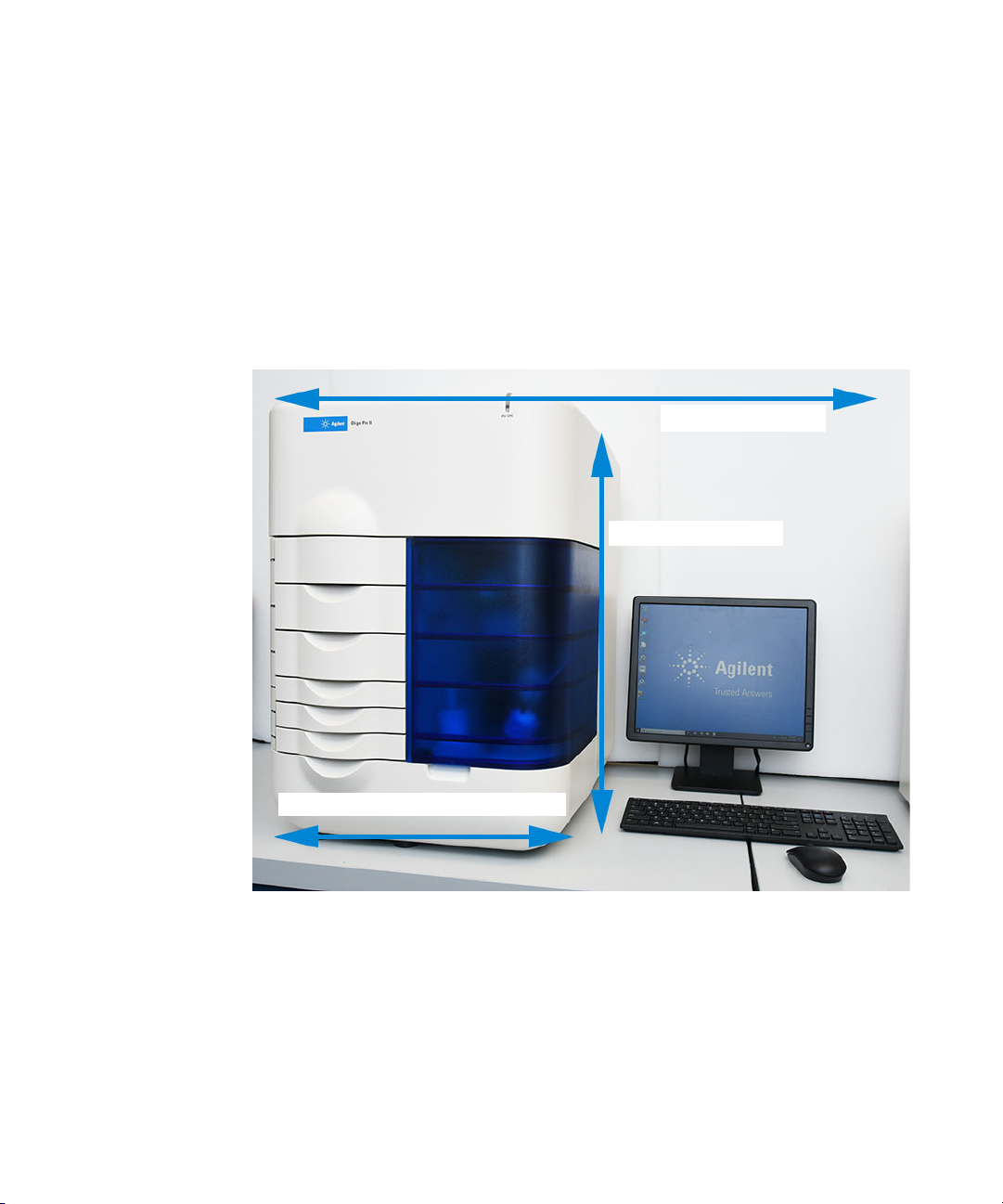
38” W (96.52 cm)
26.5” H (67.31) cm)
19” W (48.26 cm) + 24” D (61 cm)
Configured Oligo Pro II System Dimensions
Configured Oligo Pro II System Dimensions
This chapter provides a basic overview of the Oligo Pro II system hardware and
operation. Figure 1 shows an external view of a fully configured Oligo Pro II
system, which has a compact footprint of 40” on the bench top with a weight of
82 lbs (37 kg).
Figure 1 Configured Oligo Pro II system with computer workstation
Oligo Pro II User Manual 9
Page 10

1 Oligo Pro II System Overview
NOTE
NOTE
Oligo Pro II System Connections
Oligo Pro II System Connections
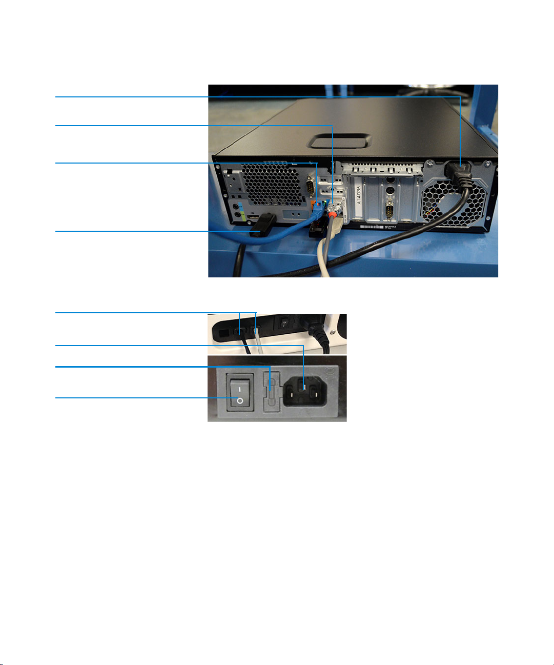
The back of the Oligo Pro II instrument contains the communications panel
where necessary connections are made to the instrument computer and
electrical outlet for operation (Figure 2 and Figure 3).
The use of a double-conversion surge protection or uninterrupted power supply
(UPS) device is highly recommended. Contact the corresponding Agilent
Sales/Service representative for specific recommended models.
A minimum of three standard electrical wall outlets should be available to
connect the instrument, computer and accessories, although a power strip can
be used in place of separate wall outlets if needed.
Each connection is labeled on the PC. The various connections between the
system and the Oligo Pro II instrument are summarized below:
• From the Oligo Pro II System:
• Two USB cables to PC USB
• Power cord to grounded electrical outlet
• From the PC:
• Two USB connections to the Oligo Pro II system
The order/location of connections is critical and the locations have been
identified on the computer.
• Power cord to grounded electrical outlet
• Connection to monitor, keyboard, mouse etc.
10 Oligo Pro II User Manual
Page 11
1 Oligo Pro II System Overview
AC power connection
USB connections from instrument
Internet connection
Computer monitor connection
USB out to computer
AC power connection
Fuse mount
Power switch
Oligo Pro II System Connections
Figure 2 Back panel computer connections
Oligo Pro II User Manual 11
Figure 3 Back panel Oligo Pro II instrument connections
Page 12
1 Oligo Pro II System Overview
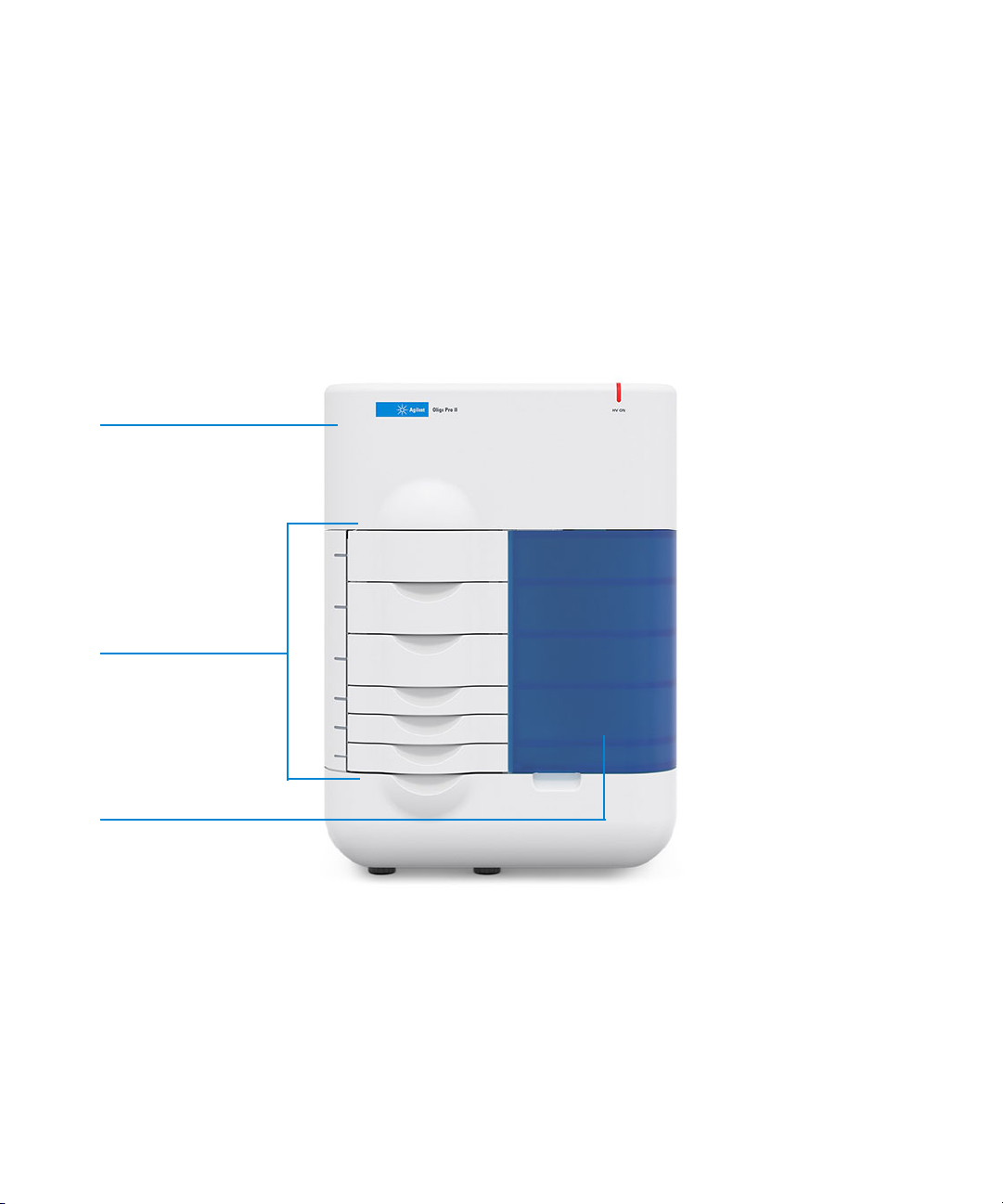
Top compartment:
Capillary array
Optics
Power supply
Drawers
Side compartment:
Pump
Reagent bottles
Oligo Pro II External Cabinet
Oligo Pro II External Cabinet
There are three primary points of access to the inside of the Oligo Pro II system:
the top compartment, the side compartment access door, and the drawers
(6 total) (Figure 4).
12 Oligo Pro II User Manual
Figure 4 Entry points of the Oligo Pro II System
Page 13
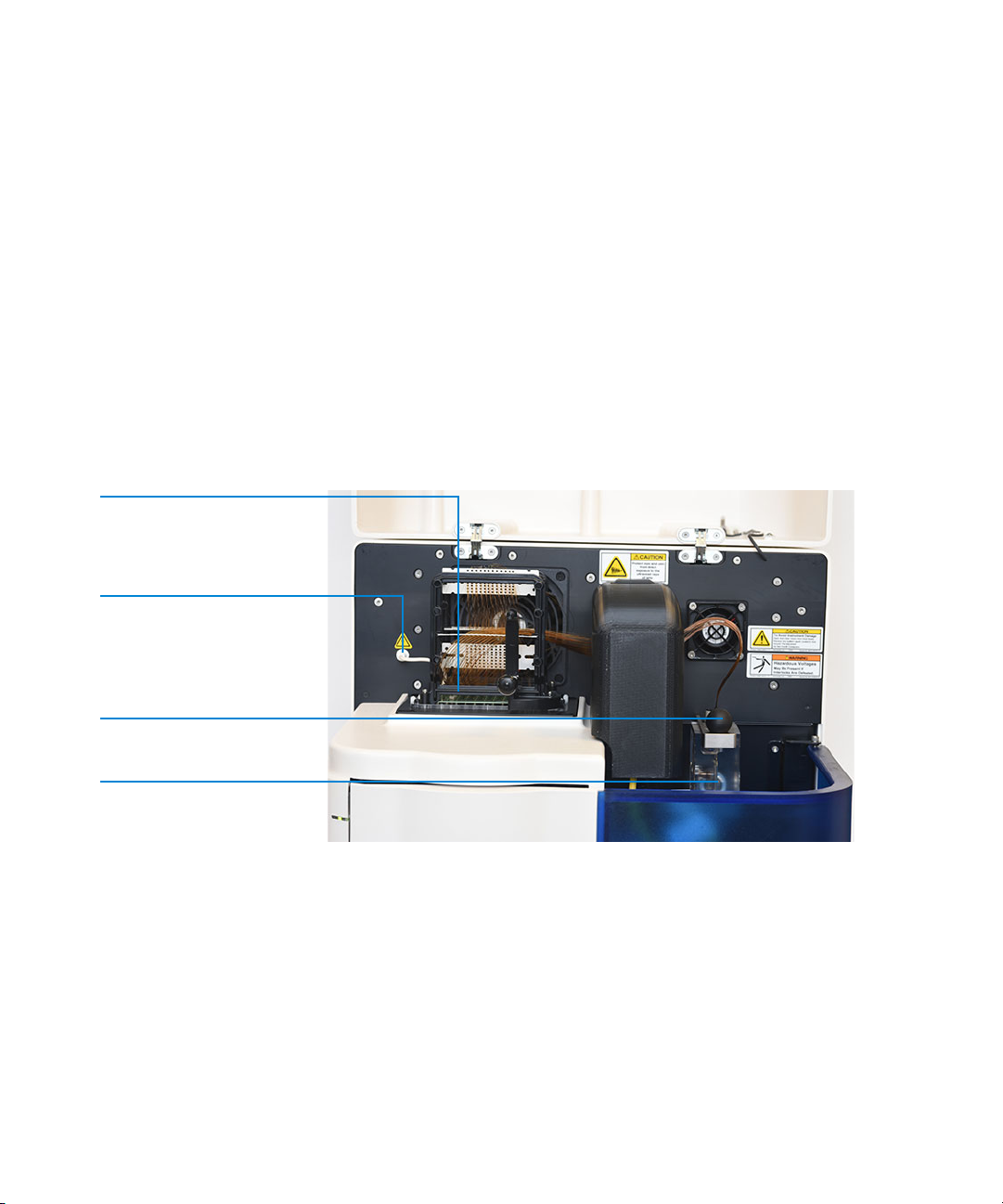
1 Oligo Pro II System Overview
Capillary array
High voltage supply cable
Capillary outlet connection
Reservoir
Top C om p ar tme nt
Top Compartment
The top compartment provides access to the optical detection platform and a
capillary array cartridge. A non-accessible compartment on the back of the
instrument contains the high voltage power supply and electronics that are
connected to the array cartridge and safety interlock system. The safety interlock
system shuts off the high voltage in case this door is opened while the
instrument is running.
The capillary array cartridge is a replaceable, modular component of the
Oligo Pro II system. You can easily exchange the capillary array cartridge. This
process is explained in Chapter 4, “Oligo Pro II Software – Utilities Menu”.
Oligo Pro II User Manual 13
Figure 5 Oligo Pro II main unit top compartment open
Page 14
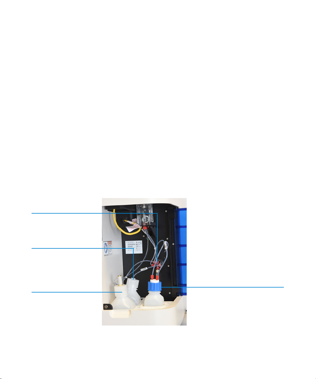
1 Oligo Pro II System Overview
6-way distribution valve
Conditioning solution
Waste
Gel 1
Side Compartment
Side Compartment
The side compartment allows access to the high pressure pump, syringe, waste
bottle, conditioning solution, and gel solution.
The High-Pressure Syringe Pumping system provides automated flushing and
filling of the capillary array with conditioning solution and separation gel,
providing pressurization of the capillaries up to 280 psi.
Two different solutions are fed to and pumped through the capillary array during
routine operation:
• Capillary Conditioning Solution
• Separation Gel (gel 1)
The appropriate solution is selected for pumping by way of a 6-way distribution
valve.
The system also contains a waste bottle, which collects solutions pumped via
the waste line from the capillary array reservoir during the filling process.
14 Oligo Pro II User Manual
Figure 6 Side door compartment
Page 15

1 Oligo Pro II System Overview
Side Compartment
The four fluid line connections inside the Oligo Pro II system are:
• Gel line from syringe pump to gel bottle (gel 1 or gel 2)
• Conditioning fluid from syringe pump to conditioning fluid
• Overflow waste line from syringe pump to waste bottle
• F-port line from syringe pump (6-way valve) to F-port
Oligo Pro II User Manual 15
Page 16

1 Oligo Pro II System Overview
Drawers
Drawers
The Oligo Pro II system front-panel drawers provide an external interface for
loading Buffer, Waste, Rinse, and Sample 96-Well Plates into the system.
• Buffer drawer (top drawer): This location is used for the inlet buffer tray used
during the CE separation.
• Waste drawer (second drawer from top): This location is used for loading the
waste tray.
• Rinse drawer (third drawer from top): This location is used for loading the
rinse tray.
• Sample drawer 1(fourth drawer from top): This location is used for sample
plate number 1.
• Sample drawer 2 (fifth drawer from top): This location is used for sample plate
number 2.
• Sample drawer 3 (sixth drawer from top): This location is used for sample
plate number 3. It is also used for a 96-well plate containing sample storage
solution.
16 Oligo Pro II User Manual
Page 17
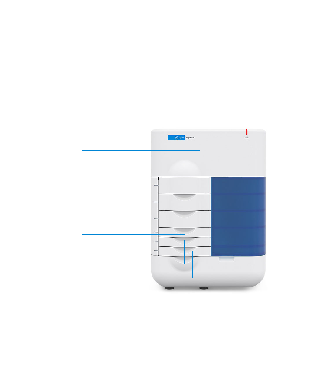
1 Oligo Pro II System Overview
Buffer drawer
Waste drawer
Rinse drawer
Drawer 2: sample
Drawer 3: sample
Drawers
Drawer Status
Status Description
Buffer and Waste Drawers are interlocked When any of the top two drawers are open, the
Rinse, Sample Drawers 1, 2, and 3 are not interlocked Sample trays can be exchanged while the instrument
high-voltage (for electrophoresis) will automatically
shut off.
is in operation.
Oligo Pro II User Manual 17
Drawer 1: sample
Figure 7 Instrument drawer positions
Page 18
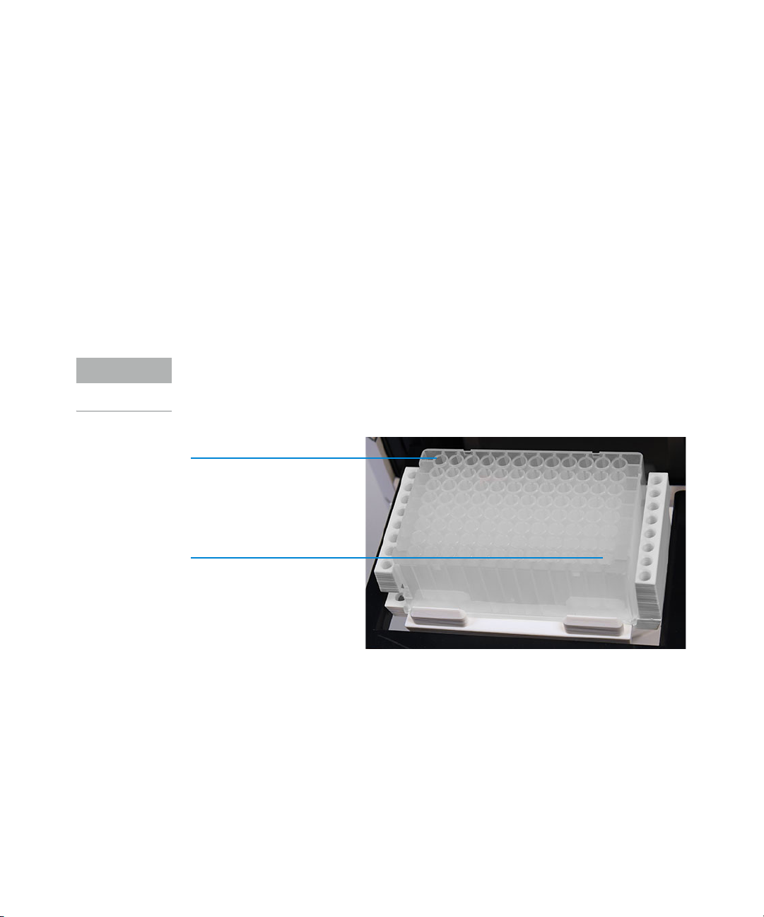
1 Oligo Pro II System Overview
NOTE
Well A1 (capillary 1)
Oligo Pro II System Loading and Orientation of 96-Well Plates
Oligo Pro II System Loading and Orientation of
96-Well Plates
The Oligo Pro II system is a multiplexed CE system containing a capillary array,
which is designed to interface directly with an entire plate of a standard 96-well
plate footprint.
Each capillary of the array corresponds to a specific well for a given row in the
96-well sample plate. For example, the capillary array orientation is indexed such
that capillary #1 corresponds to Well A1 and capillary #96 = H12.
Well A1 of the 96-well plate should always be oriented to the back left location of
the instrument drawer to ensure that the sample well location is correctly
assigned and reported in the software.
18 Oligo Pro II User Manual
Well H12 (capillary 96)
Figure 8 Proper orientation when loading 96-well buffer and sample plates for a 96-capillary system
Each drawer location houses a tray carrier containing alignment pins for ensuring
proper alignment of the 96-well plate when placed against the capillary array.
The Oligo Pro II system has been designed to operate using specific dimensions
and styles of plates.
Plates with similar dimensions may be used, but capillary damage may occur
with the use of poor-quality PCR plates.
For a list of compatible PCR plates please refer to “Compatible Plates for the
Oligo Pro II System” on page 120.
Page 19

1 Oligo Pro II System Overview
NOTE
Oligo Pro II Loading Samples
Oligo Pro II Loading Samples
The Oligo Pro II system requires a minimum volume of 20 µL/well in the sample
plate for proper injection.
When preparing sample plates for repeated use, a volume of 30 µL/well with a
20 µL (one drop) mineral oil overlay is recommended.
Check the wells of the sample plate/s after pipetting to ensure that there are no
air bubbles trapped in the bottom of the wells. The presence of trapped air
bubbles can lead to injection failures.
Air bubbles can be removed from the plates by introducing a brief centrifugation
step prior to placing the plates into the tray carrier.
Oligo Pro II User Manual 19
Page 20

2 Oligo Pro II Software – File Menu
About this Software 21
System Requirements 22
System Installation 23
Opening the Oligo Pro II Software 24
Main Screen Toolbar 26
File Menu 27
File Manager 27
Oligo Pro II Data Analysis 29
Logout 29
Exit 29
This chapter describes the Oligo Pro II software in more detail on the commands
of the File menu.
Oligo Pro II User Manual 20
Page 21

2 Oligo Pro II Software – File Menu
About this Software
About this Software
The Oligo Pro II system employs proprietary software for operation and data
analysis.
This software is preloaded on the instrument and checked prior to shipment as
part of the instrument verification.
Oligo Pro II User Manual 21
Page 22

2 Oligo Pro II Software – File Menu
System Requirements
System Requirements
The software is run using a Windows 10 PC with the following requirements:
Table 1 Minimum computer requirements
Type Specification
Processor Intel Core i5 - 8500
SVGA Video Minimum Resolution 1024 X 768
Memory 4 Gigabytes (1 x 4 GB) DDR4-2666
Available Hard Disk Space 500 Gigabytes
USB Serial Ports 6 ports (2 instrument, keyboard, mouse)
Network If not using a local database, a network connection to the database
server host is desired.
22 Oligo Pro II User Manual
Page 23

2 Oligo Pro II Software – File Menu
System Installation
System Installation
To install the Oligo Pro II software:
1 Contact your corresponding Agilent Service Representative to request the
software.
2 Navigate to Oligo Pro II Installer > setup.exe, and double-click setup.exe.
OR
Use the appropriate downloaded .exe to perform the installation.
3 Follow the setup instructions provided by the installation wizard. The default
installation directory is C:\Agilent\ Oligo PRO II.
Oligo Pro II User Manual 23
Page 24
2 Oligo Pro II Software – File Menu
Opening the Oligo Pro II Software
Opening the Oligo Pro II Software
1 To log into the software, select the Oligo Pro II software icon (Figure 9).
Figure 9 Oligo Pro II software icon
There are two levels of users available:
• Administrator: The administrator login has enhanced access to functions
such as allowing the user to edit separation methods.
•User: The user login has restricted access that allows only routine
operation of the instrument.
2 To log into the Oligo Pro II software, type Administrator or User into the User ID
field of the login window (Figure 10).
3 Enter your password.
The first time you log in, the password information is left blank.
Figure 10 Login menu
24 Oligo Pro II User Manual
Page 25
2 Oligo Pro II Software – File Menu
Opening the Oligo Pro II Software
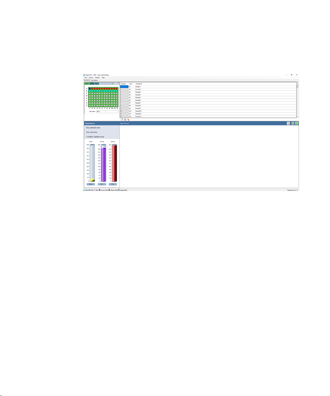
4 Click OK.
The main screen opens.
Figure 11 Oligo Pro II software main screen
More information about the User and Administrator functions within the software
are discussed in a later chapter.
A password can be set for the system during the Agilent training and installation
period at your facility or by using the Change Password command of the Admin
menu described in section “Change Password” on page 38.
The first time you log into the Oligo Pro II software, a database is displayed
indicating where the application is connected.
The database connection can be changed before logging in by clicking Browse
next to the database field.
The login information is used in event and error logging to aid in controlling
access to the system, tracking usage and monitoring changes to the system.
Every time you log into the Oligo Pro II software, you begin on the main screen
(Figure 11).
Oligo Pro II User Manual 25
Page 26

2 Oligo Pro II Software – File Menu
Main Screen Toolbar
Main Screen Toolbar
The main screen toolbar is located at the top of the Oligo Pro II software main
screen as seen in Figure 11.
26 Oligo Pro II User Manual
Page 27
2 Oligo Pro II Software – File Menu
File Menu
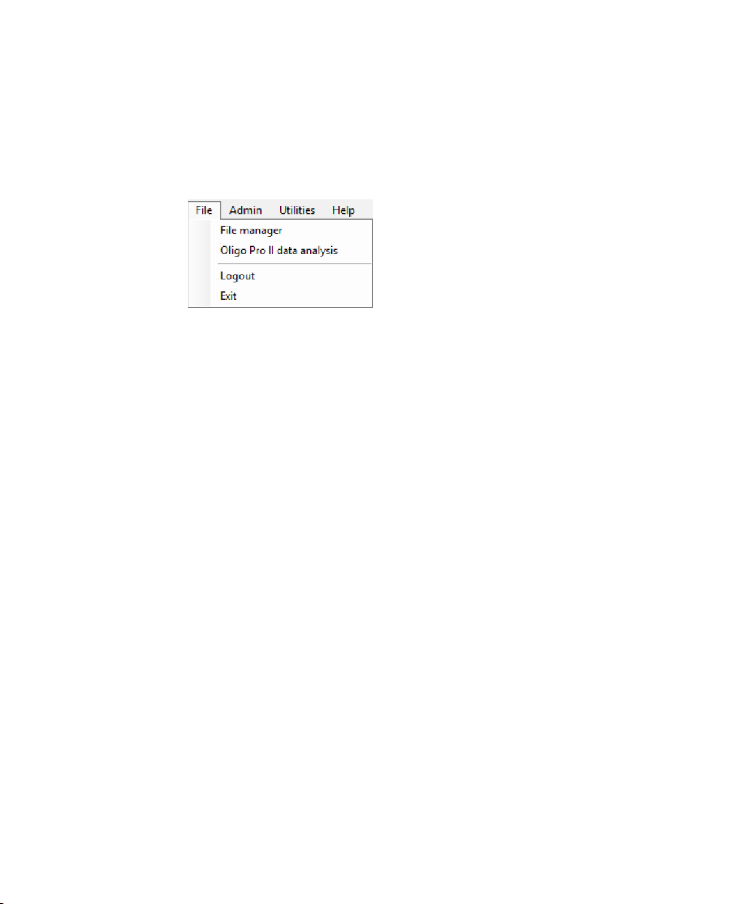
File Menu
Figure 12 File menu functions
File Manager
The File manager command allows electropherogram data to be examined within
the Oligo Pro II software environment.
Files are normally analyzed using the Oligo Pro II Data Analysis software, which is
covered in the Oligo Pro II Data Analysis Software User Manual.
The file manager also enables you to correct the capillary alignment for an
individual data file.
Select the File manager command to open a file browser and to navigate to a data
file. Once a file is selected, the file manager window opens (Figure 13).
Oligo Pro II User Manual 27
Page 28
2 Oligo Pro II Software – File Menu
File Manager
Figure 13 File manager window
Tabl e 2 lists the functions of the file manager screen.
Table 2 File manager – file functions
Field Description
Open Opens a file browser to navigate to desired data file.
Cap. Alignment Allows you to view and manipulate the capillary alignment for the data file opened
only. Capillary alignment from a file is discussed in section “Capillary Alignment” on
page 47.
Print Allows you to print the twelve electropherograms to a page.
Exit Closes the File manager window.
Tabl e 3 lists the Current, Method summary, and Sample info toolbar functions.
Table 3 File manager toolbar options
Field Description
Current Displays the current of the separation during the analysis.
Method summary Shows a summary of the method that was used for the separation.
Sample Info Shows the sample names input for the separation file.
28 Oligo Pro II User Manual
Page 29

2 Oligo Pro II Software – File Menu
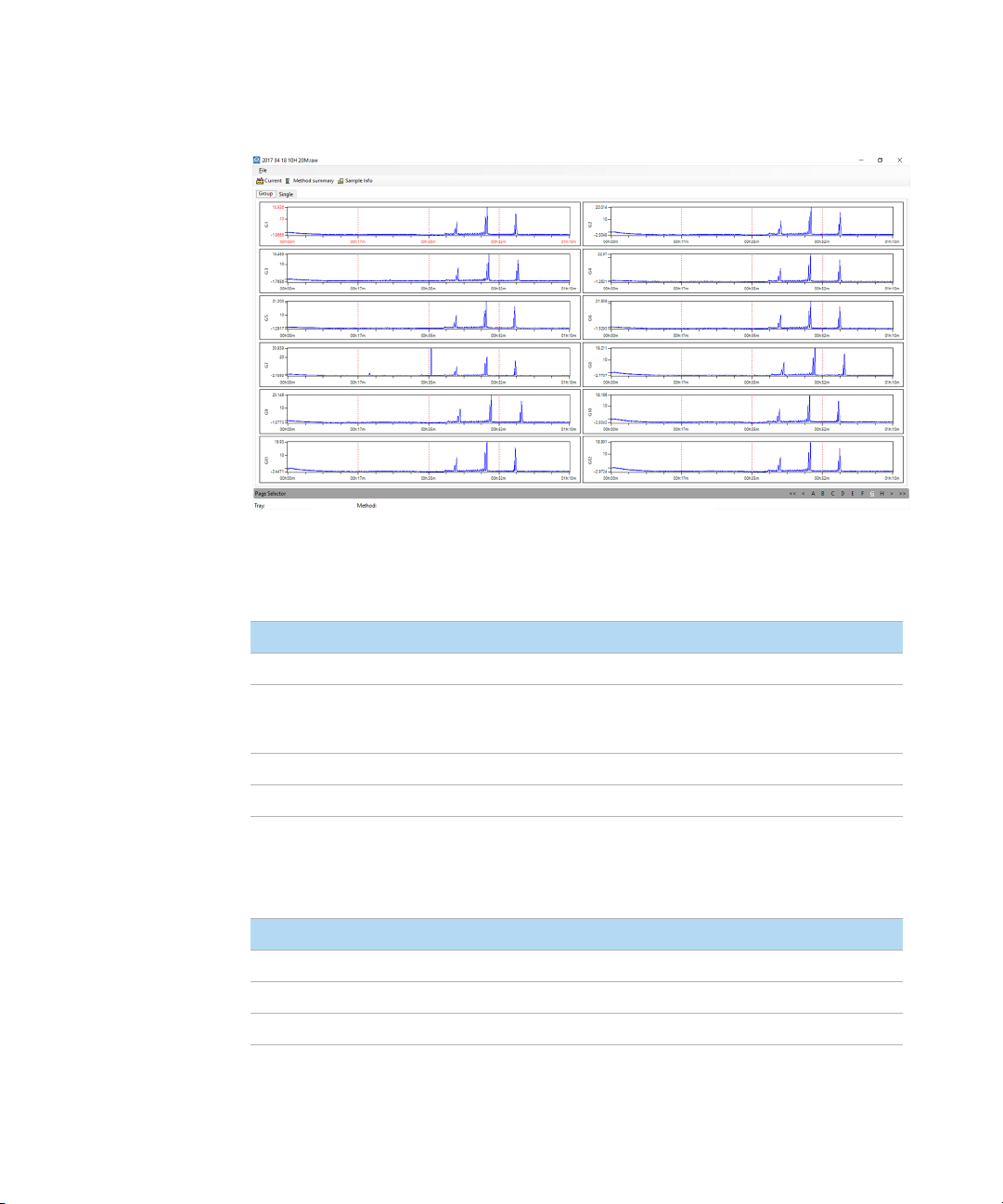
Oligo Pro II Data Analysis
Once the data file is opened in the file manager, the data can be viewed in groups
of 12 (by row) when the Group tab is selected. A page selection is located at the
bottom of the screen allowing for navigation of all rows in a plate (assuming
96-capillary array data is chosen).
To view a single electropherogram at a time, either left-click twice on the desired
well or select the Single tab. A page and well selection is located at the bottom of
the screen allowing for navigation of all rows and wells in the plate.
Electropherogram data can be panned, zoomed in, or zoomed out of by
right-clicking on the chart and selecting the function of interest.
Oligo Pro II Data Analysis
Selecting this command will open the Oligo Pro II data analysis software.
Logout
The Logout command allows you to log out of the Oligo Pro II software and to log
in as a different user.
After logout, the login menu opens (Figure 10).
Exit
The Exit command closes the Oligo Pro II software. Alternatively, you can exit the
program by selecting the red X on the top right corner of the main screen.
Oligo Pro II User Manual 29
Page 30

3 Oligo Pro II Software – Admin Menu
Admin Menu 31
Configuration 32
Change Password 38
User Maintenance 39
Archive and Purge Database 40
Event Report 41
Error Report 43
This chapter describes the Oligo Pro II software in more detail on the commands
of the Admin menu.
Oligo Pro II User Manual 30
Page 31

3 Oligo Pro II Software – Admin Menu
Admin Menu
Admin Menu
Figure 14 Admin menu commands
Oligo Pro II User Manual 31
Page 32

3 Oligo Pro II Software – Admin Menu
Configuration
Configuration
The Configuration command opens the Configurations dialog, where the
administrator modifes Security Settings, Device Settings, Bottle Volumes, and
Email parameters for the system.
In the Security Settings tab, the administrator can modify the login requirements
for all users (Figure 15).
Figure 15 Configuration settings - Security settings tab
32 Oligo Pro II User Manual
Page 33

3 Oligo Pro II Software – Admin Menu
Configuration
A summary of the parameters in the Security Settings tab is provided in Ta ble 4 .
Table 4 Configuration – Security Settings tab functions
Configuration Option Range Description
Login required True or false If true: User must log into the application.
Minimum password length 0 to 12 The password must exceed this number of
Maximum number of login
attempts
O to 12 If a user attempts to log in with an invalid
If false: No login is required for user level access.
characters
password, after this many attempts:
• That user ID is made inactive and the error
logged
• The failed login attempt is recorded in the
event log
• The application is shut down
Time to change passwords O to 36 months A password (login ID and signature) will expire
Auto logoff time O to 30 minutes If the application is left unattended for length of
Number of previous passwords O to 4 When a user changes their password, they may
after the set number of months. If set to zero,
there is no password expiration.
time, the current user will be logged off. If set to
zero, there is no automatic logoff.
not select from this number of previously used
passwords. If set to zero, there is no previous
used password restriction.
Oligo Pro II User Manual 33
Page 34

3 Oligo Pro II Software – Admin Menu
Configuration
The Device Settings tab allows modification of the device settings.
The settings should be updated whenever a new capillary array cartridge is
installed (Figure 16).
A summary of the configuration options in the Device Settings tab is provided in
Tabl e 5.
Figure 16 Configuration settings - Device settings tab
34 Oligo Pro II User Manual
Page 35

3 Oligo Pro II Software – Admin Menu
Configuration
Table 5 Configuration – Device Settings tab functions
Parameter Access Level Description
Number of capillaries Administrator Values: 12, 24 or 96
Note, selecting 12 when a 96-capillary array is installed may
cause hardware issues and ruin the array.
Capillary length Administrator Value: 55
Note that this length refers to the effective length of the
capillaries in use and uses those methods only.
Capillary array serial
number
Buffer tray Administrator Buffer tray selection is locked to Buffer Row A.
Storage solution tray User Allows for the selection of tray and row for the storage
Language User Allows the user to select language for the software (default
Language file Administrator Allows the user to change the language of the software by
Set tray name to folder
prefix
Reset tray info when
queuing
Save Administrator Saves the chosen settings.
Reload Administrator Reloads the previously saved settings.
Administrator Text field. Maximum length 14 characters.
solution tray.
is english).
selecting the appropriate (.csv) language file.
(Example: Chinese, English and German)
Administrator Allows the user to automatically set the tray name to the
folder prefix.
Administrator Automatically resets tray information when queuing multiple
runs.
Oligo Pro II User Manual 35
Page 36

3 Oligo Pro II Software – Admin Menu
Configuration
The Bottle Volumes tab allows modification of the reagent bottle volumes
(Figure 17).
The gel 1, gel 2, conditioning, and waste bottles can be set from 50 mL to
5000 mL by entering the appropriate volume of the container used in the system.
Figure 17 Configuration settings - Bottle volumes tab
The Email tab allows the user to set up e-mail settings (Figure 18).
Figure 18 Configuration settings - Email tab
36 Oligo Pro II User Manual
Page 37

3 Oligo Pro II Software – Admin Menu
NOTE
NOTE
Configuration
Information on the Host, Port number, etc. may be found at the e-mail source or
with the local site information technology administrator. For example yahoo.com
offers an e-mail settings page as shown in Figure 19.
After inputting all the desired e-mail settings, select Test Connection (green
arrow) to ensure a positive test. If the test is not positive or passed, the
parameters are not set correctly.
After passing the connection test, click Save.
Figure 19 Example outgoing mail settings
Oligo Pro II User Manual 37
Page 38

3 Oligo Pro II Software – Admin Menu
Change Password
Change Password
The command Change password opens the window shown in Figure 20.
Changing the password is accessible to all users.
Password requirements:
• Maximum password length is 40.
• Password can contain letters or numbers.
• Passwords are case insensitive.
Figure 20 Change password menu
38 Oligo Pro II User Manual
Page 39

3 Oligo Pro II Software – Admin Menu
User Maintenance
User Maintenance
The command User maintenance opens the User Maintenance window
(Figure 21).
In this window, the administrator can add, delete, and modify all users that can
access the Oligo Pro II software.
1 To edit the settings, select the pencil icon .
2 After editing, and if all entries are acceptable to the user, select the check
mark .
Figure 21 User Maintenance window
A summary of the parameters in the User Maintenance window is provided in
Tabl e 6.
Table 6 User maintenance window parameters
Field Description
User ID User ID for login or signature. This ID must be unique for the system.
Access Level Set the user access level to user or administrator.
User Name The full name of the user.
Email Users email address (optional).
Oligo Pro II User Manual 39
Page 40

3 Oligo Pro II Software – Admin Menu
Archive and Purge Database
Table 6 User maintenance window parameters
Field Description
Active Select the check box to activate the user and its user ID.
If cleared: The user ID cannot be used.
Clear Password Sets the users login password to blank. If a minimum password length has been set,
the user will need to change their password on login.
Archive and Purge Database
The Archive & purge database command is used to maintain the event and error
log database.
Event and error logs are saved in the database and can be retrieved for advanced
troubleshooting.
This function allows the user with administrative rights to back up the data for
future use in a different location or on an external storage device.
40 Oligo Pro II User Manual
Page 41

3 Oligo Pro II Software – Admin Menu
Event Report
Event Report
The Event report command provides a tabular report of the audit trail of the
events that have occurred in the Oligo Pro II software.
Selecting Event report from the Admin menu opens the Select Date Range window
where the user can select Use all dates or Use selected date range (Figure 22).
Figure 22 Select Date Range window
Users with both Administrator and User level access can view the Event Report.
The Event Report contains the following information for each event log item:
• User name: user who was logged in
• Computer name: network name of the computer where the event occurred
• Event date
• Event code action
• Description
After selecting the appropriate date range in the Select Date Range window and
selecting OK, an Event Report is generated (Figure 23).
Oligo Pro II User Manual 41
Page 42

3 Oligo Pro II Software – Admin Menu
Event Report
Figure 23 Event Report example
The icons along the top of the Event Report follow standard Windows function
nomenclature and are summarized in Figure 25.
Table 7 Event report icons and descriptions
Icon Description
Page section
Back to parent report
Stop rendering (i.e. stop report generation)
Refresh
Print
Print layout
Page setup
Save
Zoom
42 Oligo Pro II User Manual
Page 43

3 Oligo Pro II Software – Admin Menu
Error Report
Error Report
The Error report function is used for advanced troubleshooting.
Selecting the command Error report from the Admin menu opens the Select Date
Range window where you can select Use all dates or Use selected date range
(Figure 24).
Figure 24 Select Date Range window.
The Error Report captures the following information:
• Software exceptions and hardware errors detectable by the software
• User name: the user who was logged in when the error occurred
• Computer name: network name of the computer where the error occurred
• Event date
• Error code
• Description
After selecting the appropriate date range in the Select Date Range window and
selecting OK, an Error Report is generated (Figure 25).
The icons along the top of the Error Report follow standard Windows function
nomenclature and are summarized in Ta bl e 7 .
Oligo Pro II User Manual 43
Page 44

3 Oligo Pro II Software – Admin Menu
Error Report
Figure 25 Error Report window
44 Oligo Pro II User Manual
Page 45

4 Oligo Pro II Software – Utilities Menu
Utilities Menu 46
Capillary Alignment 47
Hardware Testing 51
Move Stage 53
Prime 54
Solution Levels 55
This chapter describes the Oligo Pro II software in more detail on the commands
of the Utilities menu.
Oligo Pro II User Manual 45
Page 46

4 Oligo Pro II Software – Utilities Menu
Utilities Menu
Utilities Menu
Figure 26 Utilities menu commands
46 Oligo Pro II User Manual
Page 47

4 Oligo Pro II Software – Utilities Menu
Capillary Alignment
Capillary Alignment
Capillary alignment is required when a new capillary array is installed. It may also
be performed when the instrument capillary alignment is not correct. The sign of
such an incorrect alignment is low peak intensities even when the sample
concentration is high.
When Capillary alignment is selected from the Utilities menu, the Capillary
Alignment screen opens.
Figure 27 Capillary Alignment screen
Oligo Pro II User Manual 47
Page 48

4 Oligo Pro II Software – Utilities Menu
Capillary pixel locations
Yellow boxes denote capillary
location
Baseline
Capillary Alignment
Capillary Alignment From Real-Time Window
1 Manually select the red line threshold and drag it up to the desired level.
2 From the toolbar, select Align.
3 If you have not selected all capillaries, move the threshold and realign them.
Perform the realignment until the capillaries are aligned.
4 Keep the following settings:
• Peak width: 3
• Sensitivity: 5.0
• Select the Space Checking check box
• Enter 1 frame/sec.
5 Click Save.
Capillary Alignment From File
1 From the toolbar of the Capillary Alignment window, select Read Raw.
2 Navigate to the location of the raw file using the Windows prompts.
The default saved location of raw data is:
C:/Agilent/Data/(Date: YYYY MM DD)/(Time: XXH XXM).
3 Select the latest Raw file.
4 The Align from File window opens (Figure 28), allowing the user to align the
capillaries from the selected run file. The toolbar of the Align from File window
is discussed in Table 8 .
48 Oligo Pro II User Manual
Figure 28 Align from file window for 96-capillary system
Page 49

4 Oligo Pro II Software – Utilities Menu
Capillary Alignment
Table 8 Align from file toolbar functions
Icon Description
Opens a new file
Accepts Changes to the file (i.e. Capillary locations)
Cancels any actions and closes the file
Locates the Original Capillary Positions used when the selected file ran.
Locates the capillaries based on peak positions in the selected open file.
Note: Move the red baseline up so that only the peaks of interest are
integrated and not noise from the baseline.
5 Left-click the red baseline and draw it upwards from the bottom of the graph
but not above the top of capillary peaks, as shown in Figure 28.
6 Select Locate caps from the toolbar in the Align from file window.
This will locate the capillary peaks and place a yellow box at the apex of the
selected capillaries denoting the capillary pixel location.
The bottom left corner of the screen states the number of capillaries found.
This should be 12 or 96 depending on the configuration of the instrument and
type of array in use.
If necessary, adjust the capillary positions:
• To manually adjust the capillary position, left-click the white line dissecting
the capillary and drag it left or right to the desired location.
• Should the number be off due to too many or too few capillary positions,
redraw the red baseline and repeat this step.
• To insert or delete a capillary position, right-click on the black area of the
graph or the capillary pixel location table to the right of the graph.
• Right-clicking on the graph area also allows for zooming in or out on the
graph
Oligo Pro II User Manual 49
Page 50

4 Oligo Pro II Software – Utilities Menu
Capillary Alignment
7 Once the desired number of capillaries is located, select Ok from the Align
from file toolbar. This will save any changes made to the capillary alignment
and close the Align from file window, returning you to the Capillary Alignment
screen.
8 Select Save from the Capillary Alignment window.
From this point forward the instrument will use these saved pixel locations for
all future runs.
50 Oligo Pro II User Manual
Page 51

4 Oligo Pro II Software – Utilities Menu
Hardware Testing
Hardware Testing
The command Hardware testing is available to users with administrator privileges
and is used for troubleshooting the instrument.
The Hardware testing command from the Utilities menu opens the Hardware
Testing Screen as seen in Figure 29.
Figure 29 Hardware testing screen
An overview of the functions available in the Hardware Testing Screen is listed in
Figure 29.
Oligo Pro II User Manual 51
Page 52

4 Oligo Pro II Software – Utilities Menu
Hardware Testing
Table 9 Functions of the Hardware Testing Screen
Function Description
Valves > Waste Select to open the valve. Clear to close the valve. The status of the valve
is indicated by an open/filled circle in the status bar, respectively.
Valves > Air pump Select to open the valve. Clear to close the valve. The status of the valve
is indicated by an open/filled circle in the status bar, respectively.
Valves > UV lamp Always ON
Stage > Move Moves the tray to the selected position.
Stage > Reset stage Allows the user to reset the stage position should a drawer be opened
before the stage finishes its movement.
Available on instrument serial numbers 2600, and higher.
Bottle Levels Gives a visual indication (simulation based on calculated usage) of the
amount of reagents available in the system.
52 Oligo Pro II User Manual
Page 53

4 Oligo Pro II Software – Utilities Menu
Move Stage
Move Stage
Allows the user to move the stage to the selected location. See Table 10 for
details.
Figure 30 Stage movement options
Table 10 Stage movement descriptions
Icon Description
Buffer Picks up the buffer tray from the buffer drawer and holds it against the capillary array.
Park Places the current tray being held back into its respective drawer and moves the instrument
Store Places the current tray being held back into its respective drawer and picks up the storage
platform to the bottom of the instrument allowing for buffer replacement.
solution tray to hold it against the capillary array.
Oligo Pro II User Manual 53
Page 54

4 Oligo Pro II Software – Utilities Menu
Prime
Prime
The Prime function allows the user to prime any of the three available reagent
bottle line should a new solution be added to the instrument or bubbles be found
in the reagent bottle lines.
Selecting the Prime function from the Utilities menu opens the Prime window as
seen in Figure 31. The Prime functions are discussed in Ta bl e 1 1.
Figure 31 Prime window
Table 11 Functions of the Prime window
Function Description
Fluid selected Allows the user to select which reagent line or combination of lines to prime
Cycles Refers to number of cycles (1-10) of the syringe to complete. One cycle is generally
Fill rate Allows the user to adjust the Fill rate up and down 0-1000. Gel should not be pulled
Empty rate Allows you to adjust the Empty rate up and down 0-1000. Gel should not be
(Conditioning and/or Gel 1).
sufficient.
from the gel bottle at a rate above 10 µL/s.
pushed higher than 20 µL/s.
54 Oligo Pro II User Manual
Page 55

4 Oligo Pro II Software – Utilities Menu
NOTE
Solution Levels
Solution Levels
Allows the user to adjust the volumes added to the reagent bottles and adjust the
waste bottle level when emptied.
The Oligo Pro II software tracks the solution levels as the instrument is used. This
ensures that the instrument has enough fluids for all of the planned runs.
If the solution levels are low, the software will issue a warning and ask the user to
adjust the solution levels before it can proceed with a separation.
Selecting the Solution levels command from the Utilities menu opens the Check
Solution Volumes window (Figure 32).
Figure 32 Check solutions volumes window
1 When solutions are refilled, open this window and enter the correct solution
levels (mL) for each container.
a Use the up and down arrows or enter the solution level in each entry field to
adjust solution levels.
b To save changes to solution levels, select Ok.
For the program to run correctly (i.e. to issue the correct warning), it is important
that you enter the solution levels into the program every time that new solutions
are placed onto the instrument.
Oligo Pro II User Manual 55
Page 56

5 Oligo Pro II Software – Help Menu
Help Menu 57
Tutorial Videos 57
User Manual 57
About 57
About Firmware 58
Check for Updates 58
This chapter describes the Oligo Pro II software in more detail on the commands
of the Help menu.
Oligo Pro II User Manual 56
Page 57

5 Oligo Pro II Software – Help Menu
Help Menu
Help Menu
Figure 33 Help menu commands
Tutorial Videos
Selecting Tutorial videos opens a folder containing videos made to help you with
topics such as Placing an array on the Fragment Analyzer and Performing a
Capillary Alignment.
User Manual
Navigating to the command User manual opens a drop-down list of every chapter
of the user manual.
About
The About command opens an About Oligo Pro II window displaying the version
number of software, hardware serial number, and copyright information.
Oligo Pro II User Manual 57
Page 58

5 Oligo Pro II Software – Help Menu
About Firmware
About Firmware
The About firmware command opens an About Firmware window displaying the
voltage, pump, and motion control.
Check for Updates
This will check for software updates.
58 Oligo Pro II User Manual
Page 59

6 Oligo Pro II Software – Operation Tab
Operation Tab Overview 60
Tray Selection and Sample ID 61
Experimental Run Controls and Adding to Queue 63
Method Queue 72
This chapter describes the Oligo Pro II software in more detail on the Operation
tab.
Oligo Pro II User Manual 59
Page 60

6 Oligo Pro II Software – Operation Tab
Operation Tab Overview
Operation Tab Overview
Figure 34 Oligo Pro II software main screen
60 Oligo Pro II User Manual
Page 61

6 Oligo Pro II Software – Operation Tab
Tray Selection and Sample ID
Tray Selection and Sample ID
Select the sample tray to be used from either the Sample Tray drop-down list or
the colored tab tray selection, depending which configuration is set (Figure 35).
Figure 35 Classic drop-down tray selection (left) or colored tab tray selection (right)
1 In the tray window, select .
The Visual preferences dialog window opens (Figure 36).
Figure 36 Visual preferences dialog
2 Choose between the sample tray drop-down list or the colored tab tray
selection (Figure 35).
3 If you use the colored tab tray selection window, select to change the
color of each sample tray in the Color selection window.
4 To select a row from the 96-well plate depicted in the sample and sample tray
selection window, left-click once in that row (Figure 35). To select a new row,
left-click on another row.
Oligo Pro II User Manual 61
Page 62
6 Oligo Pro II Software – Operation Tab
Tray Selection and Sample ID
5 To clear a row selection, select (Figure 35).
The Tray name field of the selection window allows you to input a name for the
tray being run (Figure 35). You can also click in this field and use a bar code
scanner to import sample names for the plate being run.
Enter sample information in the Sample ID section of the main screen (Figure 37).
For a 96-cap system, you must select each row individually to manually enter
data (rows A-H). You can also save or load sample names and information using
.txt or .csv files. These functions are discussed in Ta ble 12.
Figure 37 Sample information editor
Table 12 Sample information editor functions
Item Description
Load from file Loads sample names from a .txt or .csv based file.
Save tray Saves the information entered for an entire sample tray.
Reset tray Resets the entire sample tray to the default Sample ID settings.
62 Oligo Pro II User Manual
Page 63

6 Oligo Pro II Software – Operation Tab
Experimental Run Controls and Adding to Queue
Experimental Run Controls and Adding to Queue
The Oligo Pro II software provides pre-loaded default methods for both capillary
array conditioning and experimental methods for each analysis kit offered by
Agilent.
The experimental run controls shown in Figure 38 shows the controls available
for Run selected rows, Run entire tray, and Condition capillary array. These options
are discussed below.
Reagent levels of the bottles are also shown.
Figure 38 Experimental run controls
Oligo Pro II User Manual 63
Page 64

6 Oligo Pro II Software – Operation Tab
Experimental Run Controls and Adding to Queue
Run Entire Tray
Selecting Run entire tray opens the Separation Setup window (Figure 39). Select a
method using the drop-down list (Figure 40).
Figure 39 Run entire tray window
64 Oligo Pro II User Manual
Page 65

6 Oligo Pro II Software – Operation Tab
Experimental Run Controls and Adding to Queue
Figure 40 Separation setup window with method drop-down list expanded
The functions of the Separation Setup window are discussed in Tab le 1 3.
Table 13 Separation Setup window functions
Item Description
Method Select a method from the drop-down list (Figure 39).
Tray name The Tray name is shown as input by the user on the main screen or the
Folder prefix The folder prefix allows you to add a prefix to the folder name where the
Copy results /copy path The default directory location for the data is C:\Agilent\Data. Select Copy
Notes Allows to add any additional information you may require for a set of
Merge rows When using a 12- or 24-capillary array, select this option to merge several
default name appears.You may edit this field by typing in the provided
field.
results files will be written.
results, and click […] to navigate to a different location where you want to
copy the saved data.
samples.
runs for data analysis.
Oligo Pro II User Manual 65
Page 66

6 Oligo Pro II Software – Operation Tab
Experimental Run Controls and Adding to Queue
After choosing an appropriate method from the drop-down list and providing
appropriate notes, copy paths, etc., select Ok to add the chosen method to the
method queue, select or Cancel to close the window.
The settings icon in the top of the Separation Setup window opens the
method editor window (Figure 41). Here, you can define a new method, or edit
the existing method prior to executing a run.
In the method editor window, select a method from the drop-down list. To create
a new method, select File > Save as and save as the new method with a unique
name. If you want to edit and save the existing method, select Save to accept the
changes and close the window. To edit the current method for the current run
without permanently saving the method, select OK.
Figure 41 Method editor window
The method editor window allows for customization of the run parameters for a
CE separation.
Select the check box next to the individual parameters to enable different steps
and parameters. The individual parameters are discussed in Tab le 1 4.
66 Oligo Pro II User Manual
Page 67

6 Oligo Pro II Software – Operation Tab
Experimental Run Controls and Adding to Queue
Table 14 Method editor window functions
Item Description
Perform Prerun A short pre-run is recommended to normalize the gel inside the capillaries.
Rinse The rinse option allows you to dip into the selected position rinsing the capillary tips
Sample Injection Define the Voltage and Time for the voltage injection.
Separation Define the Voltage and Time of the CE Separation.
and electrodes between the pre-run and sample injection. The Tray position, Row,
and Dip count can be altered as well.
Oligo Pro II User Manual 67
Page 68

6 Oligo Pro II Software – Operation Tab
Experimental Run Controls and Adding to Queue
Condition Capillary Array
Selecting Condition capillary array opens the Select Conditioning Method window
(Figure 42). Select a method using the drop-down list (Figure 43).
Figure 42 Select Conditioning Method window
68 Oligo Pro II User Manual
Page 69

6 Oligo Pro II Software – Operation Tab
Experimental Run Controls and Adding to Queue
Figure 43 Select Conditioning Method window with method drop-down list expanded
After choosing an appropriate method from the drop-down list, select OK to add
the chosen method to the method queue, or Cancel to close the screen.
Select to open the condition capillary array method editor window, which
allows the user with administrator privileges to define a new conditioning
method, or to edit the existing method prior to executing a run. The conditioning
method editor window is shown in Figure 44.
Users with user level are allowed to view the method parameters of the selected
file in the Method Summary.
To create a new method, select File > Save as and save as the new method with a
unique name. If you want to edit and save the existing method, select Save to
accept the changes and close the window. To edit the current method for the
current run without permanently saving the method select OK.
Oligo Pro II User Manual 69
Page 70

6 Oligo Pro II Software – Operation Tab
Experimental Run Controls and Adding to Queue
Figure 44 Condition capillary array method editor
The condition capillary array method editor window allows for customization of
the run parameters for a CE separation. The individual parameters are discussed
in Table 15 .
70 Oligo Pro II User Manual
Page 71

6 Oligo Pro II Software – Operation Tab
Experimental Run Controls and Adding to Queue
Table 15 Condition capillary array method editor window settings
Item Description
Step 1, 2, or 3 Enables/disables the step to be used.
Time Total time of the conditioning step.
Fill pressure Maximum fill pressure. This should be set < 300 psi:
Solution Select Conditioning solution or Gel 1 reagent bottles for use.
Fill reservoir rate The rate at which the syringe fills the reservoir.
Fill capillary rate The rate at which the syringe fills the capillaries. This should be no greater than
10 µL/s for a gel, and up to 200 µL/s for capillary conditioning fluid.
Time Total time of conditioning step.
Fill syringe from solution The rate at which the syringe fills from the selected solution.
Pull from reservoir The rate at which the syringe pulls liquid from the reservoir. For the Oligo Pro II
system this should never exceed 30 µL/sec.
Hold pressure rate The rate at which the syringe will pressurize the capillaries to maintain
pressure.
Push to waste The rate at which the syringe will empty to waste.
Tray Select the tray to pump into when conducting the conditioning. Always pump
to buffer tray when pushing gel through capillaries to avoid drying the capillary
tips.
Oligo Pro II User Manual 71
Page 72

6 Oligo Pro II Software – Operation Tab
Method Queue
Method Queue
Once a sample tray has been selected, sample names are entered into the
Sample ID field. When Add to queue has been selected, the chosen method is
shown in the method queue (Figure 45).
Figure 45 shows three sample runs chosen from sample trays 1, 2, and 3
followed by a pause in the method queue and a priming method.
Figure 45 Method queue
A Pause or Prime can be inserted into the method queue by selecting the method
queue area of the screen. When Insert Prime is selected, the Prime window opens,
prompting the user to choose the bottle location to prime from a drop-down list
(Figure 46).
Figure 46 Prime window
Methods loaded into the method queue can be moved up or down based on the
user’s needs by left-clicking on the method and dragging it to the desired location
in the queue.
To view the parameters for the separation method in the method queue, select
Method summary next to the separation method. A summary of the method will
appear, as shown in Figure 47.
72 Oligo Pro II User Manual
Page 73

6 Oligo Pro II Software – Operation Tab
Method Queue
Figure 47 Method summary window
Select Edit from the Method summary window allows you to make final changes
to the method if desired.
To cancel only the separation method in the queue, select X next to the
separation method.To delete all items in the queue, select from the method
queue run control toolbar.
To expand the method and show a detailed summary, select the down arrows
next to the separation method.
There are three run controls for the method queue: Clear the Method Queue,
Pause the Method Queue, and Start the Method Queue. These run controls are
shown in Ta bl e 16.
Oligo Pro II User Manual 73
Page 74

6 Oligo Pro II Software – Operation Tab
Method Queue
Table 16 Method queue run controls
Icon Description
Clear Clears all separation methods, pauses, and primes from the queue.
Pause Pauses the method queue. The current method running will still complete.
Start Starts the method queue. Once started the top method will disappear and
To restart the queue select the start icon.
the screen will switch to the run status tab. The next method will move up
in the queue.
74 Oligo Pro II User Manual
Page 75

7 Oligo Pro II Software - Run Status Tab
Run Status Tab Overview 76
Stage Movement Animation 77
Conditioning Animation 78
Pre-Run / Injection View 79
Real-Time Separation View 80
Status Bar 82
This chapter describes the Oligo Pro II software in more detail on the Run Status
tab.
Oligo Pro II User Manual 75
Page 76

7 Oligo Pro II Software - Run Status Tab
Run Status Tab Overview
Run Status Tab Overview
Once Start has been selected (for more information, refer to Chapter 6, “Oligo
Pro II Software – Operation Tab”), the display will switch from the Operation tab
to the Run Status tab.
76 Oligo Pro II User Manual
Page 77

7 Oligo Pro II Software - Run Status Tab
Stage Movement Animation
Stage Movement Animation
Whenever the stage moves from one position to another, the animation shows
where the Oligo Pro II stage is moving to/from (Figure 48). This provides a
real-time view of what is happening.
Figure 48 Stage movement animation
Oligo Pro II User Manual 77
Page 78

7 Oligo Pro II Software - Run Status Tab
Conditioning Animation
Conditioning Animation
When the Oligo Pro II instrument is pumping conditioning solution or gel, the
animation in Figure 49 is shown. The animation gives a real-time view of exactly
what the instrument is doing during a conditioning and/or gel/fill sequence.
Figure 49 Conditioning animation
78 Oligo Pro II User Manual
Page 79

7 Oligo Pro II Software - Run Status Tab
Pre-Run / Injection View
Pre-Run / Injection View
When the Oligo Pro II instrument is completing a pre-run or injection, the screen
in Figure 50 is shown.
Figure 50 Pre-run/injection screen
Oligo Pro II User Manual 79
Page 80

7 Oligo Pro II Software - Run Status Tab
Real-Time Separation View
Real-Time Separation View
When the Oligo Pro II instrument starts the separation, the screen shows the
real-time view of the separation (Figure 51).
Figure 51 Real-time separation window
The Group tab at the top shows the run in a group of 12 electropherograms. The
Single tab shows individual electropherograms.
When a 96-capillary system is running, you can select between rows of a group
on the bottom left of the electropherograms by select the corresponding letter of
the row. When viewing the Single tab, you can also select the well number to
view.
Other options available from the Run Status tab are discussed in Ta bl e 17 .
80 Oligo Pro II User Manual
Page 81

7 Oligo Pro II Software - Run Status Tab
Real-Time Separation View
Table 17 Run status tab options
Icon Description
Opens a popup window showing the method summary for the current
method being run.
Aborts only the individual task being done, i.e. stage movement, pumping, or
injection.
Aborts the entire method being run and begins the next method in the queue.
If no methods are found, the stage returns to the storage position. When
selected, a window asks to verify if you really want to abort.
Shows the current for the separation being performed.
Task status Shows the status bar and time left for each individual task being
accomplished, i.e. stage movement, pumping, or injection.
Method status Shows the status bar and time left for the entire method to complete.
Oligo Pro II User Manual 81
Page 82

7 Oligo Pro II Software - Run Status Tab
Status Bar
Status Bar
The bottom bar of the Oligo Pro II software shows a real-time status bar
containing important information about the instrument status. These functions
are discussed in Tab le 18.
Table 18 Instrument Status Information
Icon Description
Left-clicking on this icon will show the voltage level for the last 5 minutes.
Left-clicking on this icon will show the current level for the last 5 minutes.
Left-clicking on this icon will show the pressure level for the last 5 minutes.
The blue circle denotes high voltage present and states that the LED is on. If
the circle is grey, the LED is turned off and the message reads LED OFF.
Denotes if the waste valve is open or closed.
Denotes the location of the stage at that point in time.
82 Oligo Pro II User Manual
Page 83

8 Oligo Pro II Software – Sample Name Entry
Sample Name Entry 84
Entering Sample Names Manually 84
Importing Sample Names 85
Importing Sample Names Using a Bar-Code Reader 87
This chapter provides information on how to enter the sample names in the Oligo
Pro II software.
Oligo Pro II User Manual 83
Page 84

8 Oligo Pro II Software – Sample Name Entry
Sample name entry
Save file
Load from file
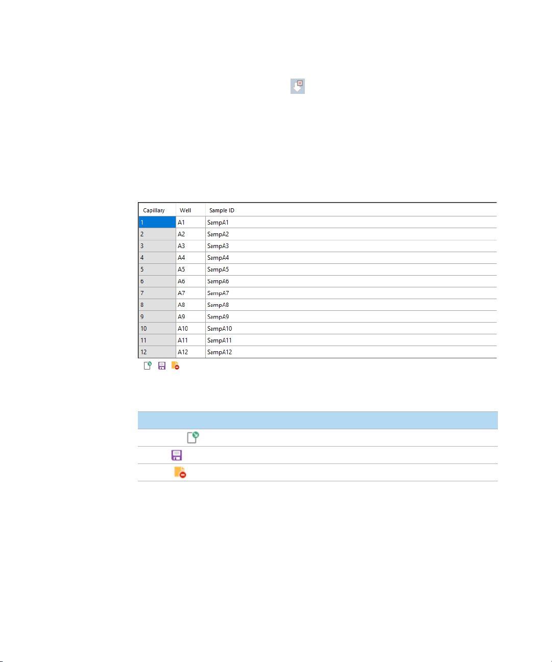
Sample Name Entry
Sample Name Entry
Entering Sample Names Manually
1 From the Operation tab, select the tray number, the desired row, and the
sample cell.
2 In the field Sample ID, enter the desired sample names.
3 Save the file as a .txt or .csv using the save functions (Figure 52).
84 Oligo Pro II User Manual
Figure 52 Manual sample entry
Page 85

8 Oligo Pro II Software – Sample Name Entry
Importing Sample Names
Importing Sample Names
✔ The files must be available in .txt or .csv file format.
✔ The data format must comply with the format described below in order for the
system to read the files correctly.
1 In the Operation tab, select Load from file to load a set of saved or previously
created sample names.
• For a .txt file, a single column of sample names are used (Figure 53)
Figure 53 txt file format (single row of names—no well numbers or row numbers)
Oligo Pro II User Manual 85
Page 86

8 Oligo Pro II Software – Sample Name Entry
Importing Sample Names
• For a .csv file, the format is row number, well number, and sample name
(Figure 54).
Figure 54 .csv file format: row number, well number, sample name
86 Oligo Pro II User Manual
Page 87

8 Oligo Pro II Software – Sample Name Entry
Importing Sample Names Using a Bar-Code Reader
Importing Sample Names Using a Bar-Code Reader
For the purposes of sample name import, a bar code reader is equivalent to a
keyboard. When a bar-code is read, the program searches the Samples folder for
a name that is identical to the bar-code. If a name is found, then the file (and the
corresponding sample names) is imported.
1 Place the sample name files into the C:/Agilent/Samples folder. If a folder
does not exist, create a new Samples folder (Figure 55). The sample name file
can be either a .txt file or .csv file (using the formats described in section
“Importing Sample Names” on page 85). The sample name files are created
by the user, or automatically by a LIMS system.
Figure 55 Samples folder
It is critical that the name of the file is identical to what is read by the bar-code
reader.
Example:
In Figure 56, the name associated with the bar-code is 00060065.
Figure 56 Bar code 00060065
Oligo Pro II User Manual 87
Page 88

8 Oligo Pro II Software – Sample Name Entry
Importing Sample Names Using a Bar-Code Reader
Thus, the .csv file or .txt file must be given the file name 00060065 and placed
in the Samples folder (Figure 59).
Figure 57 File name 00060065
2 In the field Tray name of the Operation tab, highlight the tray name with the
mouse cursor (Figure 58).
Figure 58 Highlighted tray name
88 Oligo Pro II User Manual
Page 89

8 Oligo Pro II Software – Sample Name Entry
Importing Sample Names Using a Bar-Code Reader
3 Use the bar-code reader to scan the bar-code on the plate.
The names are automatically imported (Figure 59).
Figure 59 Imported sample names
Oligo Pro II User Manual 89
Page 90

9 Oligo Pro II Capillary Array
Capillary Array Parts 91
Removal of the Capillary Array 92
Unpacking a New Capillary Array 101
Capillary Array Installation 107
This chapter explains the essential operational parameters of the capillary array.
Oligo Pro II User Manual 90
Page 91

9 Oligo Pro II Capillary Array
Capillary array frame
Capillary Array Parts
Capillary Array Parts
The Oligo Pro II instrument capillary array allows for direct parallel injection and
separation of 12, 24, or 96 samples at once.
The capillary array cartridge is located in the upper compartment of the
instrument and accessed by opening the instrument hood.
Capillary array bundle
Capillary tips and electrodes
Alignment pins
Oligo Pro II User Manual 91
Figure 60 Capillary array parts (12-capillary array shown)
Page 92

9 Oligo Pro II Capillary Array
Removal of the Capillary Array
Removal of the Capillary Array
This section provides a guideline to remove a capillary array cartridge from the
Oligo Pro II instrument.
Before proceeding with the capillary array removal, got to Utilities > Move Stage
and select the park icon to place the stage into the park position and ensure all
trays have been returned to their corresponding drawers.
1 Open the top hood of the instrument.
Figure 61 Oligo Pro II instrument, top with hood open.
92 Oligo Pro II User Manual
Page 93

9 Oligo Pro II Capillary Array
Removal of the Capillary Array
2 Unplug the white high voltage supply cable for the top front panel and place in
the holder of the capillary array frame.
Holder
High voltage cable
Figure 62 Instrument top compartment – high voltage supply cable
Oligo Pro II User Manual 93
Page 94

9 Oligo Pro II Capillary Array
NOTE
Removal of the Capillary Array
3 Remove the window guard.
Avoid looking directly at the light.
Figure 63 Instrument top compartment – window guard removal
4 Pull out the capillary reservoir connector slide.
Figure 64 Instrument top compartment – capillary reservoir connector slide
94 Oligo Pro II User Manual
Page 95

9 Oligo Pro II Capillary Array
Removal of the Capillary Array
5 Use the capillary reservoir connector tool to loosen the capillary array bundle
by prying up on the bundle.
Figure 65 Instrument top compartment – capillary reservoir connector tool
Oligo Pro II User Manual 95
Page 96

9 Oligo Pro II Capillary Array
NOTE
Removal of the Capillary Array
6 Remove the capillary array bundle by pulling up gently.
Avoid pulling up hard as to not break any capillaries.
Figure 66 Instrument top compartment – capillary array bundle removal
7 Carefully insert the protective cover over the capillary bundle.
Figure 67 Instrument top compartment – installing protective cover
96 Oligo Pro II User Manual
Page 97

9 Oligo Pro II Capillary Array
Removal of the Capillary Array
8 Place the capillary array bundle on the top holder of the capillary array
window.
Figure 68 Instrument top compartment – storing covered capillary array bundle
Oligo Pro II User Manual 97
Page 98

9 Oligo Pro II Capillary Array
NOTE
Removal of the Capillary Array
9 Remove the capillary array window from the window holder.
Do not press on or touch the capillaries.
Figure 69 Instrument top compartment – remove capillary array window
10 Flip the array window after removal so that the capillary array bundle goes
from the right to the left side of the array frame.
98 Oligo Pro II User Manual
Page 99

9 Oligo Pro II Capillary Array
Removal of the Capillary Array
11 Attach the array window to the capillary array frame using the attachment
screw.
Figure 70 Instrument top compartment – attach array window to capillary array frame
12 Use the provided hex wrench to remove the two white screws holding the
capillary array in place.
Figure 71 Instrument top compartment – array attachment screw removal
Oligo Pro II User Manual 99
Page 100

9 Oligo Pro II Capillary Array
Removal of the Capillary Array
13 Carefully lift the array straight up to remove it from the Oligo Pro II instrument.
Figure 72 Instrument top compartment – capillary array removal
Once removed from the instrument, the capillary array cartridge is ready for
disposal or storage.
100 Oligo Pro II User Manual
 Loading...