

Page 1
Keysight Technologies
PNA Family
Microwave Network Analyzers
(N522x/3x/4xB)
Configuration Guide
Page 2

02 | Keysight | PNA Family Microwave Network Analyzers - Configuration Guide
Table of Contents
PNA Family Network Analyzer Congurations ................................................................5
Test set and power conguration options ............................................................5
Hardware options ...............................................................................6
Application software .............................................................................6
Accessories, calibration options ....................................................................8
PNA-X Series Test Set and Power Conguration Options .......................................................9
PNA Series Test Set and Power Conguration Options ........................................................14
PNA-L Series Test Set and Power Conguration Options ......................................................17
PNA Family Application Options. . . . . . . . . . . . . . . . . . . . . . . . . . . . . . . . . . . . . . . . . . . . . . . . . . . . . . . . . . . . . . . . . . . . . . . . . .18
Measurement application software ................................................................18
Noise gure options and applications ..............................................................21
PNA-X block diagrams with noise gure option ......................................................22
Noise gure measurement summary ...............................................................23
Pulse, antenna, mm-wave applications and options ...................................................24
Nonlinear vector network analysis .................................................................24
Accessories ...................................................................................25
PNA Family Network Analyzer Upgrade Kits ................................................................26
Frequency, test ports, test set and power congurations ...............................................26
Upgrade paths ................................................................................27
Applications ........................................................................................28
Material measurements .........................................................................28
Signal integrity measurements ...................................................................28
Multiport measurements ........................................................................28
Millimeter-wave measurements ...................................................................29
Measurement Accessories ..............................................................................30
Cables and adapter sets .........................................................................30
Calibration kits ................................................................................30
For devices with 1.0 mm connectors ...............................................................31
For devices with 1.85 mm connectors ..............................................................31
For devices with 2.4 mm connectors ...............................................................32
For devices with K (2.92 mm) connectors ...........................................................32
For devices with 3.5 mm or SMA connectors ........................................................33
For devices with Type-N connectors ...............................................................35
For devices with 7 mm connectors ................................................................36
For devices with waveguide ......................................................................36
Verication kits ................................................................................37
General Accessories ...................................................................................37
Spare drive ...................................................................................37
Probe ........................................................................................38
Power meters and sensors .......................................................................38
Comb generators ..............................................................................38
Ampliers ....................................................................................38
Couplers .....................................................................................38
Equipment rack accessories. . . . . . . . . . . . . . . . . . . . . . . . . . . . . . . . . . . . . . . . . . . . . . . . . . . . . . . . . . . . . . . . . . . . . .38
Monitors .....................................................................................38
Interface cables ...............................................................................38
www.keysight.com/find/pna
Page 3
03 | Keysight | PNA Family Microwave Network Analyzers - Configuration Guide
This configuration guide describes standard configurations,
options, accessories, upgrade kits and compatible peripherals for
the PNA Family microwave network analyzers. This guide should
be used with the Keysight Technologies, Inc. PNA Family data
sheets for a complete description of these analyzers.
PNA-X Series
N5249B 10 MHz to 8.5 GHz
N5241B 10 MHz to 13.5 GHz
N5242B 10 MHz to 26.5 GHz
N5244B 10 MHz to 43.5 GHz
N5245B 10 MHz to 50 GHz
N5247B 10 MHz to 67 GHz
PNA Series
N5221B 10 MHz to 13.5 GHz
N5222B 10 MHz to 26.5 GHz
N5224B 10 MHz to 43.5 GHz
N5225B 10 MHz to 50 GHz
N5227B 10 MHz to 67 GHz
PNA-L Series
N5239B 300 kHz to 8.5 GHz
N5231B 300 kHz to 13.5 GHz
N5232B 300 kHz to 20 GHz
N5234B 10 MHz to 43.5 GHz
N5235B 10 MHz to 50 GHz
www.keysight.com/find/pna
Page 4

04 | Keysight | PNA Family Microwave Network Analyzers - Configuration Guide
Keysight offers the following options for all PNA Family network analyzers
Certification options
Commercial calibration certification with test data (Option UK6)
Complete set of measurements which tests unit to manufacturer’s
published specifications. Includes calibration label, calibration
certificate, and data report. Conforms to ISO 9001.
ISO 17025 compliant calibration (Option 1A7)
Complete set of measurements which tests unit to manufacturer’s
published specifications. Includes calibration label, ISO 17025
calibration certificate, and data report, measurement uncertainties and guardbands on all customer specifications. Conforms to
ISO 17025 and ISO 9001.
ANSI Z540 compliant calibration (Option A6J)
Complete set of measurements which tests unit to manufacturer’s
published specifications. Includes pre- and post-adjustment
data with measurement uncertainty information compliant to the
ANSI/NCSL Z540 standard.
Documentation
The PNA Series instruments are equipped with an Online Help
system available within the instrument in English only. All PNA
documentation is available on the web:
www.keysight.com/find/pna
Calibration Software Licenses
Built-in performance test software for standard
compliant cal (S93898A)
Adds built-in performance testing and calibration sof tware
for self-maintainers. Requires additional equipment. See the
analyzer’s Service Guide for more information on equipment
required.
www.keysight.com/find/pna
Page 5

05 | Keysight | PNA Family Microwave Network Analyzers - Configuration Guide
PNA Family Network Analyzer Configurations
PNA-X Series
N5249B 10 MHz to 8.5 GHz
N5241B 10 MHz to 13.5 GHz
N5242B 10 MHz to 26.5 GHz
N5244B 10 MHz to 43.5 GHz
N5245B 10 MHz to 50 GHz
PNA Series
N5221B 10 MHz to 13.5 GHz
N5222B 10 MHz to 26.5 GHz
N5224B 10 MHz to 43.5 GHz
N5225B 10 MHz to 50 GHz
N5227B 10 MHz to 67 GHz
PNA-L Series
N5239B 300 kHz to 8.5 GHz
N5231B 300 kHz to 13.5 GHz
N5232B 300 kHz to 20 GHz
N5234B 10 MHz to 43.5 GHz
N5235B 10 MHz to 50 GHz
N5247B 10 MHz to 67 GHz
Test set and power configuration options
Choose one test set and power configuration option. Option 2xx indicates two test ports. Option 4xx indicates four test ports. To add options to a product,
order the corresponding item number (N52xxB-xxx).
Description
PNA-X Series
Option 201
Option 217
Option 219
Option 222
Option 224
Option 401
Option 417
Option 419
Option 422
Option 423
Option 425
1
1
1
1
1
1
1
1
Configurable
Tes t Set
●
● ● ●
● ● ● ●
● ● ● ● ● ●
● ● ● ● ● ● ●
● ●
● ● ● ●
● ● ● ● ●
● ● ● ● ● ●
● ● ● ● ● ● ●
● ● ● ● ● ● ● ●
Source
Attenuators
Receiver
Attenuators Bias-tees
Second
Source
Internal
Combiner
Mechanical
Switches
Internal
LowFrequency
Extension Additional Information
Not available on 67 GHz model
Not available on 67 GHz model
Not available on 67 GHz model
Not available on 67 GHz model
Only available on N5242/45/47B
PNA Series
Option 200
Option 201
Option 205
Option 210
Option 217
Option 219
Option 400
Option 401
Option 410
Option 417
Option 419
1
1
1
1
1
●
● ● ●
● ● ●
● ● ● ●
●
● ●
●
● ● ● ●
● ● ● ● ●
Only available on N5222/27B
2-port metrology option
Not available on 67 GHz model
4-port metrology option
Not available on 67 GHz model
PNA-L Series
Option 200
Option 216
Option 400
Option 416
1. To independently control the frequency of the second internal source, one of the following software applications is required: S93080/029/082/083/084/086/
2. Adds one source attenuator to be shared with all test ports.
2
087/089/090x/093/094A, or S94510/511A.
● ●
● ●
Available on only N5231/32B
Available on only N5231/32B
www.keysight.com/find/pna
Page 6

06 | Keysight | PNA Family Microwave Network Analyzers - Configuration Guide
PNA Family Network Analyzer Configurations (continued)
PNA-X Series
N5249B 10 MHz to 8.5 GHz
N5241B 10 MHz to 13.5 GHz
N5242B 10 MHz to 26.5 GHz
N5244B 10 MHz to 43.5 GHz
N5245B 10 MHz to 50 GHz
N5247B 10 MHz to 67 GHz
PNA Series
N5221B 10 MHz to 13.5 GHz
N5222B 10 MHz to 26.5 GHz
N5224B 10 MHz to 43.5 GHz
N5225B 10 MHz to 50 GHz
N5227B 10 MHz to 67 GHz
PNA-L Series
N5239B 300 kHz to 8.5 GHz
N5231B 300 kHz to 13.5 GHz
N5232B 300 kHz to 20 GHz
N5234B 10 MHz to 43.5 GHz
N5235B 10 MHz to 50 GHz
Hardware options
For PNA-X
Description
Add IF inputs N524xB-020 N522xB-020 n/a Used for antenna measurements and mm-wave extenders
Add pulse modulator to first source N524xB-021 N522xB-021 n/a
Add pulse modulator to second source N524xB-022 N522xB-022 n/a Requires one of Option 22x, 40x, 41x, or 42x
Add low-noise receiver N524xB-029 n/a n/a S93029A application software is needed to control the noise
Application software
1
Series
For PNA-X
Description
Automatic fixture removal S9 3007A S93007A S9 3007A
Time domain analysis S93010A S93010A S93010A
Enhanced time domain analysis with TDR S9 3011A S93011A S9 3011A Includes all capabilit y of S93010A
Dynamic uncertainty for S-parameter
measurements
Basic pulsed-RF measurements S93025A S93025A n/a Includes control of internal pulse generators and provides pulse
Advanced pulsed-RF measurements S93026A S93026A n/a Includes control of internal pulse generators, and provides pulse
Noise figure measurements with vector correction2S93029A S93029A n/a Standard receivers are used if hardware option N524xB-029 is
Frequency-offset measurements S93080A S93080A S93080A Provides ability to independently set the frequency of internal
Scalar mixer/converter measurements S93082A S93082A S93082A Provides SMC measurement class. S93082A is a subset of S93083A.
Vector and scalar mixer/converter measurements3 S93083A S93083A n/a Provides SMC+Phase and VMC measurement classes
Embedded-LO capability S93084A S93084A n/a Works with S93029/082/083/086/087A
Gain-compression measurements S93086A S93086A n/a
Intermodulation distor tion measurements
Source phase control S93088A S93088A n/a
Differential and I/Q device measurements S93089A S93089A n/a Requires a 4-por t test set option (4xx)
1. Suppor ted soft ware license t ypes: fixed-perpetual (1FP), transportable-perpetual (1TP), fixed-1-year (1FY), and transportable-1-year (1TY)
2. For N522xB and N5241/42/49B, vector-noise-corrected measurements require an ECal for use as an impedance tuner. For N5244/45/47B with Option 029,
an internal tuner is included. Noise calibration requires a power meter when using a standard receiver. When using the low-noise receiver (Option 029),
either a power meter or a 346-series noise source is required (Keysight 346C or 346C-K01 recommended). A power meter is required for measuring mixers
and converters.
3. A configurable test set is required for VMC measurements to connect a reference mixer, or for SMC+Phase measurements using the comb-generator-based
calibration. When ordered with PNA test set Options 200, 210, 400, or 410 (no front-panel jumpers), phase and delay measurements can only by done using
SMC+Phase with a calibration mixer.
4. S93087A can be used without PNA-X Options 22x or 42x, but exernal equipment such as a signal generator and a combiner may be required. Refer to page
19 for more details.
5. S93015A is not available on N5231B and N5232B.
4
Series
S93015A S93015A S93015A5Displays the measurement uncer tainty dynamically (real-time) on
S9 3087A S93087A n/a Not available with PNA test set options 200, 210, 400, and 410
For PNA
Series
For PNA
Series
For PNA-L
Series Additional Information
receiver for noise figure and noise power measurements. For
N5241/42/49B, requires one of options 21x, 22x, 41x, or 42x. For
N5244/45/47B, requires one of options 22x or 42x. On N5245B,
Option 029 cannot be ordered with Option 425. On N5247B, noise
receiver works up to 50 GHz only.
For PNA-L
Series Additional Information
Not available with LFE enabled on N5222B/27B -205,
N5242B/45B/47B-425.
the measurement trace.
widths to 200 ns using wideband detection
widths to 100 ns using wideband detection, and 20 ns using
narrowband detection
not present
sources and receivers, and to configure external sources. This
functionality is included with S93029/082/083/084/086/087/
089/090x/093/094A or S94510/511A.
www.keysight.com/find/pna
Page 7

07 | Keysight | PNA Family Microwave Network Analyzers - Configuration Guide
PNA Family Network Analyzer Configurations (continued)
PNA-X Series
N5249B 10 MHz to 8.5 GHz
N5241B 10 MHz to 13.5 GHz
N5242B 10 MHz to 26.5 GHz
N5244B 10 MHz to 43.5 GHz
N5245B 10 MHz to 50 GHz
PNA Series
N5221B 10 MHz to 13.5 GHz
N5222B 10 MHz to 26.5 GHz
N5224B 10 MHz to 43.5 GHz
N5225B 10 MHz to 50 GHz
N5227B 10 MHz to 67 GHz
PNA-L Series
N5239B 300 kHz to 8.5 GHz
N5231B 300 kHz to 13.5 GHz
N5232B 300 kHz to 20 GHz
N5234B 10 MHz to 43.5 GHz
N5235B 10 MHz to 50 GHz
N5247B 10 MHz to 67 GHz
Application software1 (continued)
For PNA-X
Description
Spectrum analysis, up to 8.5 GHz
Spectrum analysis, up to 13.5 GHz
Spectrum analysis, up to 26.5 GHz
Spectrum analysis, up to 43.5 GHz
Spectrum analysis, up to 50 GHz
Spectrum analysis, up to 67 GHz
Spectrum analysis, up to 90 GHz
Spectrum analysis, up to 120 GHz S93093A S93093A n/a
Spectrum analysis, beyond 120 GHz S93094A S93094A n/a
Active hot parameters S9 3110A n/a n/a Export-controlled version
Active hot parameters S9 3111A n/a n/a Requires a 4-port test set option (4xx)
Fast CW measurements S9 3118A S93118A n/a
True-mode stimulus S93460A S93460A n/a Requires a 4-por t test set option (4xx)
N-port measurements
3
Nonlinear vector network analysis
Nonlinear component characterization S94510A
Nonlinear component characterization S94511A
Nonlinear X-parameters
Nonlinear pulse-envelope domain S94 518A n/a n/a Requires hardware option 021 and application software S94510A
Arbitrary load-impedance X-parameters
Arbitrary load-control X-parameters
1. Supported software license types: f ixed-perpetual (1FP), transportable-perpetual (1TP), fixed-1-year (1FY), and transportable-1-year (1TY) (note: S93093A, S93094A, S93898A,
and S94510A have fixed-license types only).
2. For use with PNA or PNA-X models, a test set with internal receiver attenuators is recommended to avoid receiver compression when measuring large input signals. For use with
PNA-L models, test set option 216 or 416 is recommended so that external attenuators can be connected via the front-panel jumpers to avoid receiver compression as needed.
3. When ordering a test set, select an appropriate interface kit. Refer to Multiport Measurements section on page 28 for more details.
4. When N524xB is configured as a multiport analy zer using S93551A and a multiport test set, the combiner feature of Option 22x or 42x is temporarily disabled. When configured as
a standalone analyzer, the combiner feature is enabled.
5. A fully configured NVNA system requires two comb generators with power supplies, Keysight calibration kits (mechanical or ECal), and a power meter and sensor or USB power
sensor.
6. Pulse capabilit y requires option 021 and S93025A or S93026A.
7. Pulse capability requires option 021, 022 and S93025A or S93026A.
8. Requires EXG, MXG, or PSG signal generator for X-parameter ex traction (the PNA-X’s 10 MHz reference output can be used for 10 MHz tone-spacing applications).
9. X-parameters is a trademark and registered trademark of Keysight Technologies in the U.S., Europe, Japan, and elsewhere. The X-parameters format and underlying equations are
open and documented. For more information, visit www.keysight.com/find/eesof-x-parameters-info.
2
2
2
2
2
2
2
5
8,9
8,9
8,9
Series
S930900A S930900A S930900A
S930901A S930901A S930901A
S930902A S930902A S930902A
S930904A S930904A S930904A
S930905A S930905A S930905A
S9 3090 7A S 930 907A n/a
S930909A S930909A n/a
S93551A
S94514A
S94520A n/a n/a Requires application sof tware S94514A and an additional
S94521A n/a n/a Requires application software S94520A
For PNA
Series
For PNA-L
Series Additional Information
Requires a 4-port test set option (4xx)
LFE is disabled with Option 425
LFE is disabled with Option 425
4
S93551A S93551A Not available with test set options 200, 210, 400, and 410
6
6
7
n/a n/a Requires test set option 41x or 42x
n/a n/a Export-controlled version. Requires test set option 41x or 42x
n/a n/a Requires test set option 42x and application software S94510A
or S94511A
or S94511A, and S93025A or S93026A
load-control application.
www.keysight.com/find/pna
Page 8

08 | Keysight | PNA Family Microwave Network Analyzers - Configuration Guide
PNA Family Network Analyzer Configurations (continued)
PNA-X Series
N5249B 10 MHz to 8.5 GHz
N5241B 10 MHz to 13.5 GHz
N5242B 10 MHz to 26.5 GHz
N5244B 10 MHz to 43.5 GHz
N5245B 10 MHz to 50 GHz
N5247B 10 MHz to 67 GHz
PNA Series
N5221B 10 MHz to 13.5 GHz
N5222B 10 MHz to 26.5 GHz
N5224B 10 MHz to 43.5 GHz
N5225B 10 MHz to 50 GHz
N5227B 10 MHz to 67 GHz
PNA-L Series
N5239B 300 kHz to 8.5 GHz
N5231B 300 kHz to 13.5 GHz
N5232B 300 kHz to 20 GHz
N5234B 10 MHz to 43.5 GHz
N5235B 10 MHz to 50 GHz
Accessories, calibration options
Description For PNA-X Series For PNA Series For PNA-L Series Additional Information
Accessories
Rack mount kit for use without handles N524xB-1CM N522xB-1CM N523xB-1CM
Rack mount kit for use with handles N524xB-1CP N522xB-1CP N523xB-1CP
Pulse I/O adapter N1966A N1966A n/a
Comb generator
Calibration software
Built-in performance test software for standard compliant calibration
Calibration documentation
ISO 17025 compliant calibration N524xB-1A7 N522xB-1A7 N523xB-1A7
Commercial calibration certicate with test data N524xB-UK6 N522xB-UK6 N523xB-UK6
ANSI Z540 compliant calibration N524xB-A6J N522xB-A6J N523xB-A6J
1. A fully conf igured NVNA system requires two comb generators with power supplies, Keysight calibration kits (mechanical or ECal), and a power meter and sensor or USB power sensor.
2. Additional hardware required. Please refer to the analyzer’s service guide for required service-test equipment.
1
U9391C/F/G n/a n/a
2
S93898A S93898A S93898A
www.keysight.com/find/pna
Page 9

09 | Keysight | PNA Family Microwave Network Analyzers - Configuration Guide
Test port 1
R1
Test port 2
R2
A B
Source 1
OUT 1 OUT 2
Pulse
modulator
R A B C D
IF inputs
Rear panel
To receivers
LO
Pulse generators
Test port 1
R1
Test port 2
R2
35 dB
65 dB
35
dB
65 dB
A B
Source 1
OUT 1 OUT 2
Pulse
modulator
R A B C D
IF inputs
Rear panel
To receivers
LO
Pulse generators
Test port 1
R1
Test port 2
R2
35 dB
65 dB
35
dB
65 dB
A B
Source 1
OUT 1 OUT 2
Pulse
modulator
R A B C D
IF inputs
Rear panel
To receivers
LO
Pulse generators
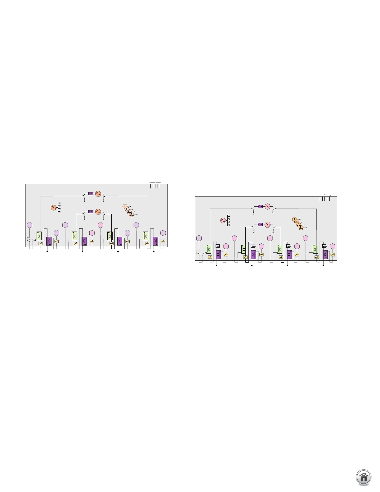
PNA-X Series Test Set and Power Configuration Options
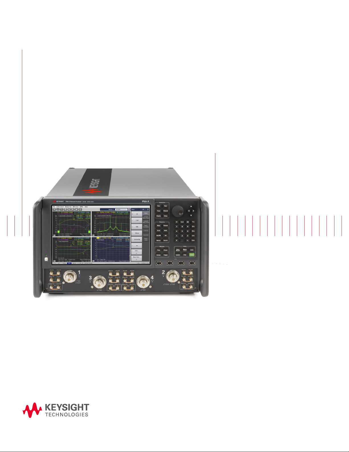
The PNA-X is an integrated vector network analyzer featuring
a built-in S-parameter test set, one or two synthesized sources
used for device stimulus, a solid-state drive, USB interfaces,
and a 12.1” LCD touch screen display. The N5241B, N5242B, and
N5249B have 50 ohm, ruggedized 3.5 mm (m) test ports. The
N5244B and the N5245B have 50 ohm, ruggedized 2.4 mm (m)
test ports. The N5247B has 50 ohm, ruggedized 1.85 mm (m)
test ports. Included with each instrument is a mouse, keyboard
(U.S. style), and one day of on-site productivity assistance
(PS-S20-PNA).
A test set and power configuration option is mandatory, choose
one of the following:
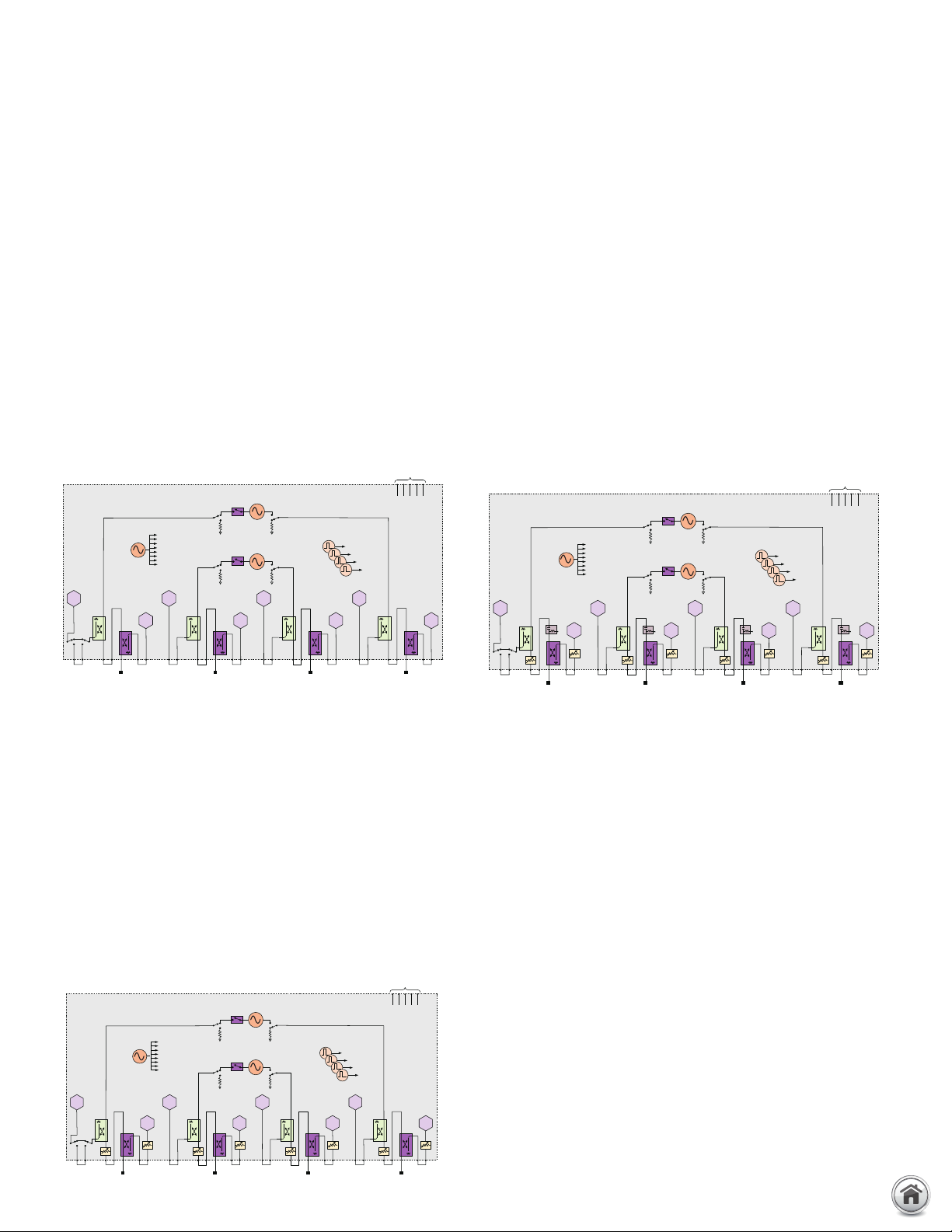
2-ports, single source, with configurable test set
(Option 201)
The standard 2-port test set comes with six front-panel access
loops. The loops provide access to the signal path between (a)
the source output and the reference receiver, (b) the source
output and directional coupler thru arm and (c) the coupled arm
of the directional coupler and the port receiver. The standard
test set also includes a solid-state internal RF bypass switch in
the R1 reference-receiver path.
2-ports, single source, with extended power
range (Option 217)
This configuration comes with front-panel access loops, and
source and receiver attenuators at each port. The source attenuators are settable in 5 dB steps up to 65 dB in N5241/42/49B,
and in 10 dB steps up to 60 dB in N5244/45B. The receiver
attenuators are settable in 5 dB steps up to 35 dB. The maximum
power rating on the test port couplers is +43 dBm (additional
attenuators or isolators are typically required to protect other
components inside the instrument). Option 217 is not available on
the N5247B.
1
1. The block diagrams shown above include hardware that must be ordered
as separate options, such as pulse modulators (Options 021 and 022),
and IF access (Option 020), or is controlled by application soft ware, as
is the case for the pulse generators. In addition, the combiner type and
attenuator values var y by model number. Refer to the product data sheet
for the correct block diagram for a specif ic model.
2-ports, single source, with extended power
range and bias-tees (Option 219)
This configuration comes with front-panel access loops, and
bias tees and source and receiver attenuators at each port. The
source attenuators are settable in 5 dB steps up to 65 dB in
N5241/42/49B, in 10 dB steps up to 60 dB in N5244/45B, and in
10 dB steps up to 50 dB in N5247B. The receiver attenuators are
settable in 5 dB steps up to 35 dB in N5241/42/44/45/49B, and
10 dB steps up to 50 dB in N5247B. The bias tees are connected
directly to the test port couplers, which limits the maximum power
rating on the pair to +30 dBm (additional attenuators or isolators
are typically required to protect other components inside the
instrument).
www.keysight.com/find/pna
Page 10

10 | Keysight | PNA Family Microwave Network Analyzers - Configuration Guide
R1
Test port 2
R2
A
B
To receivers
LO
Source 2
Output 1
Source 2
Output 2
Pulse generators
Rear panel
1
2
3
4
Test port 1
Source 1
OUT 1 OUT 2
Pulse
modulator
Source 2
OUT 1 OUT 2
Pulse
modulator
J9J10J11 J8 J7 J2 J1
35 dB
65 dB
35 dB
65 dB
J6 J5
RF
OUT
LO
OUT
R R1 R2A B
IF inputs
R1
Test port 2
R2
A
B
To receivers
LO
Source 2
Output 1
Source 2
Output 2
Pulse generators
Rear panel
1
2
3
4
Test port 1
Source 1
OUT 1 OUT 2
Pulse
modulator
Source 2
OUT 1 OUT 2
Pulse
modulator
J9J10J11 J8 J7 J2 J1
35 dB
65 dB
35 dB
65 dB
J6 J5
RF
OUT
LO
OUT
R R1 R2A B
IF inputs
PNA-X Series Test Set and Power Configuration Options1 (continued)
2-ports, dual sources, with extended power
range, combiner, and mechanical switches
(Option 222)
Along with the access loops and attenuators of Option 217,
Option 222 includes an internal second source, a combiner,
mechanical switches, and more access loops. The internal
second source provides an additional signal (fixed or swept) for
two-tone intermodulation testing of amplifiers, or for use as a
local oscillator for testing mixers and frequency converters. The
mechanical switches switch the combiner in and out as needed,
as well as enabling the additional access loops for advanced
configurations. The second source is available through two
RF connectors on the front panel, from port 1 when combined
with source 1, or via rear-panel access loops. The maximum
power rating on the test port couplers is +43 dBm (additional
attenuators or isolators are typically required to protect other
components inside the instrument). Option 222 is not available
on the N5247B. To independently control the frequency of the
second internal source, one of the following sof tware applications is required: S93080/029/082/083/084/086/087/
089/090x/093/094A.
2-ports, dual sources, with extended power
range, bias tees, and mechanical switches
(Option 224)
Along with the access loops, attenuators, and bias tees of Option
219, Option 224 includes an internal second source, a combiner,
mechanical switches, and more access loops. The internal
second source provides an additional signal (fixed or swept) for
two-tone intermodulation testing of amplifiers, or for use as a
local oscillator for testing mixers and frequency converters. The
mechanical switches switch the combiner in and out as needed,
as well as enabling the additional access loops for advanced
configurations. The second source is available through two RF
connectors on the front panel, from port 1 when combined with
source 1, or via rear-panel (N5241/42/44/45/49B) or front-panel
(N5247B) access loops. The bias tees are connected directly to
the test port couplers, which limits the maximum power rating
on the pair to +30 dBm (additional attenuators or isolators are
typically required to protect other components inside the instrument). To independently control the frequency of the second
internal source, one of the following software applications is
required: S93080/029/082/083/084/086/087/089/090x/093/0
94A.
1. The block diagrams shown above include hardware that must be ordered
as separate options, such as pulse modulators (Options 021 and 022),
and IF access (Option 020), or is controlled by application soft ware, as
is the case for the pulse generators. In addition, the combiner type and
attenuator values var y by model number. Refer to the product data sheet
for the correct block diagram for a specif ic model.
www.keysight.com/find/pna
Page 11
11 | Keysight | PNA Family Microwave Network Analyzers - Configuration Guide
Test port 3
C
R3
Test port 1
R1
Test port 4
R4
Test port 2
R2
A D B
Source 2
OUT 1 OUT 2
Pulse
modulator
Source 1
OUT 1 OUT 2
Pulse
modulator
Pulse generators
To receivers
LO
R A B C D
IF inputs
Rear panel
Test port 3
C
R3
Test port 1
R1
Test port 4
R4
Test port 2
R2
35 dB
65 dB
35 dB
65 dB 65 dB
35 dB
65 dB
A
35 dB
D B
Source 2
OUT 1 OUT 2
Pulse
modulator
Source 1
OUT 1 OUT 2
Pulse
modulator
Pulse generators
To receivers
LO
R A B C D
IF inputs
Rear panel
C
R3
R1
R4 R2
35 dB
65 dB
35 dB
65 dB 65 dB
35 dB
65 dB
A
35 dB
D B
OUT 1 OUT 2
Pulse
modulator
OUT 1 OUT 2
Pulse
modulator
To receivers
LO
R A B C D
IF inputs
Rear panel
Source 1
Source 2
Test port 1
Test port 3
Test port 2
Pulse generators
Test port 4
PNA-X Series Test Set and Power Configuration Options
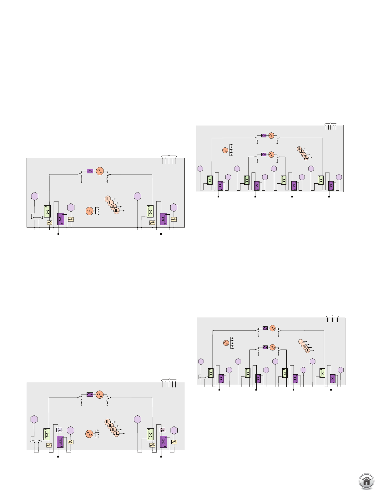
4-ports, dual sources, with configurable test set
(Option 401)
The standard 4-port test set comes with 12 front-panel access
loops and a built-in second source. The loops provide access to
the signal path between (a) the source output and the reference
receiver, (b) the source output and directional coupler thru arm
and (c) the coupled arm of the directional coupler and the port
receiver. The internal second source provides an additional
signal (fixed or swept) for two-tone intermodulation testing of
amplifiers, or for use as a local oscillator when testing mixers and
frequency converters. Source 1 is accessible through test ports 1
and 2, and source 2 is accessible through test ports 3 and 4. The
standard test set also includes a solid-state internal RF bypass
switch in the R1 reference-receiver path. To independently
control the frequency of the second internal source, one of the
following software applications is required: S93080/029/082/083
/084/086/087/089/090x/093/094A.
4-ports, dual sources, with extended power range
and bias-tees (Option 419)
This configuration comes with two sources, front-panel access
loops, and bias tees and source and receiver attenuators at
each port. The source attenuators are settable in 5 dB steps
up to 65 dB in N5241/42/49B, in 10 dB steps up to 60 dB in
N5244/45B, and in 10 dB steps up to 50 dB in N5247B. The
receiver attenuators are settable in 5 dB steps up to 35 dB in
N5241/42/44/45/49B, and 10 dB steps up to 50 dB in N5247B.
The bias tees are connected directly to the test port couplers,
which limits the maximum power rating on the pair to +30 dBm
(additional attenuators or isolators are typically required to
protect other components inside the instrument). To independently control the frequency of the second internal source, one of
the following software applications is required:
S93080/029/082/083/084/086/087/089/090x/093/094A or
S94510/511A.
1
(continued)
4-ports, dual sources, with extended power range
(Option 417)
This configuration comes with two sources, front-panel access
loops, and source and receiver attenuators at each port. The
source attenuators are settable in 5 dB steps up to 65 dB in
N5241/42/49B, and in 10 dB steps up to 60 dB in N5244/45B.
The receiver attenuators are settable in 5 dB steps up to 35 dB.
The maximum power rating on the test port couplers is +43 dBm
(additional attenuators or isolators are typically required to protect
other components inside the instrument). Option 417 is not available on the N5247B. To independently control the frequency of the
second internal source, one of the following sof tware applications
is required: S93080/029/082/083/084/086/087/089/090x/093/0
94A, and S94510/511A.
1. The block diagrams shown above include hardware that must be ordered
as separate options, such as pulse modulators (Options 021 and 022),
and IF access (Option 020), or is controlled by application soft ware, as
is the case for the pulse generators. In addition, the combiner type and
attenuator values var y by model number. Refer to the product data sheet
for the correct block diagram for a specif ic model.
www.keysight.com/find/pna
Page 12

12 | Keysight | PNA Family Microwave Network Analyzers - Configuration Guide
Test port 3
C
R3
Test port 1
R1
Test port 4
R4
Test port 2
R2
A
D
B
To receivers
LO
Pulse generators
Rear panel
1
2
3
4
Source 1
OUT 1 OUT 2
Pulse
modulator
Source 2
(standard)
OUT 1 OUT 2
Pulse
modulator
J9J10J11 J8 J7 J2 J1J4 J3
35 dB 35 dB 35 dB
35 dB
65 dB 65 dB 65 dB 65 dB
J6 J5
RF
OUT
LO
OUT
R A B C D
IF inputs
PNA-X Series Test Set and Power Configuration Options
4-ports, dual sources, with extended power
range, combiner, and mechanical switches
(Option 422)
Along with two sources and the access loops and attenuators of
Option 417, Option 422 includes a combiner, mechanical switches, and more access loops. The internal second source provides
an additional signal (fixed or swept) for two-tone intermodulation
testing of amplifiers, or for use as a local oscillator for testing
mixers and frequency converters. The mechanical switches
switch the combiner in and out as needed, as well as enabling the
additional access loops for advanced configurations. The second
source drives ports 3 and 4, and is also available from port 1
when combined with source 1, or via rear-panel access loops.
The maximum power rating on the test port couplers is +43
dBm (additional attenuators or isolators are typically required
to protect other components inside the instrument). Option 422
is not available on the N5247B. To independently control the
frequency of the second internal source, one of the following
software applications is required: S93080/029/082/083/084/
86/087/089/090x/093/094A or S94510/511A.
4-ports, dual sources, with extended power
range, bias tees, combiner, and mechanical
switches (Option 423)
Along with two sources and the access loops, attenuators,
and bias tees of Option 419, Option 423 includes a combiner,
mechanical switches, and more access loops. The internal
second source provides an additional signal (fixed or swept) for
two-tone intermodulation testing of amplifiers, or for use as a
local oscillator for testing mixers and frequency converters. The
mechanical switches switch the combiner in and out as needed,
as well as enabling the additional access loops for advanced
configurations. The second source drives ports 3 and 4, and
is also available from port 1 when combined with source 1, or
via rear-panel (N5241/42/44/45/49B) or front-panel (N5247B)
access loops. The bias tees are connected directly to the test
port couplers, which limits the maximum power rating on the
pair to +30 dBm (additional attenuators or isolators are typically
required to protect other components inside the instrument).
To independently control the frequency of the second internal
source, one of the following software applications is required:
S93080/029/082/083/084/086/087/089/090x/093/094A or
S94510/511A.
1
(continued)
1. The block diagrams shown above include hardware that must be ordered
as separate options, such as pulse modulators (Options 021 and 022),
and IF access (Option 020), or is controlled by application soft ware, as
is the case for the pulse generators. In addition, the combiner type and
attenuator values var y by model number. Refer to the product data sheet
for the correct block diagram for a specif ic model.
www.keysight.com/find/pna
Page 13

13 | Keysight | PNA Family Microwave Network Analyzers - Configuration Guide
Standard source
10 MHz - 26.5/50/67.5 GHz
Pulse modulator
R1
A
Test
port
A'
LF source
900 Hz - 100 MHz
R1'
External bias
PNA-X Series Test Set and Power Configuration Options
4-ports, dual sources, with extended power
range, bias tees, combiner, mechanical switches,
and low-frequency extension (Option 425)
Along with two sources and the access loops, attenuators, bias
tees, combiner, and mechanical switches of Option 423, Option
425 adds additional hardware to extend the star t frequency of
the PNA-X down to 900 Hz. This test set option is only available
for N5242B, N5245B, and N5247B models. The extended start
frequency is available only for the following measurement
classes: standard, gain compression (amplifier and converters),
and for magnitude-only measurements using SMC (scalar mixer/
converter) or SMC+Phase. In the standard channel, pulsed RF,
true-mode stimulus, and source phase control are not supported
for measurements below 10 MHz. To independently control the
frequency of the second internal source, one of the following
software applications is required: S93080/029/082/083/084/
086/087/089/090x/093/094A or S94510/511A. The block
diagram below shows how the low-frequency hardware1 is
configured for one test port; the other test ports are configured
similarly. For test port 1, the combiner and noise tuner (not
shown) are only available for use down to 10 MHz, and for test
port 2, the low-noise receiver (not shown) is only available for
use down to 10 MHz. Option 029 low-noise receiver cannot be
ordered with Option 425 on N5245B. The block diagram shown
includes a pulse modulator that must be ordered separately
(Option 021 or 022).
(continued)
1. The maximum allowable power to the low frequency ex tension path is limited to + 20 dBm. The input power to the test por t and the
CPLR THRU jumper must be reduced to ≤ 20 +dBm in high-power-measurement setups.
www.keysight.com/find/pna
Page 14

14 | Keysight | PNA Family Microwave Network Analyzers - Configuration Guide
Test port 1 Test port 2
A B
R1
R2
Source
OUT 1OUT 2
Pulse
modulator
To receivers
LO
Pulse generators
RABCD
IF inputs
Rear panel
Test port 1
R1
Test port 2
R2
A B
Source
OUT 1OUT 2
Pulse
modulator
To receivers
LO
Pulse generators
RABCD
IF inputs
Rear panel
Standard source
10 MHz - 26.5/50/67.5 GHz
Pulse modulator
R1
A
Test
port
A'
LF source
900 Hz - 100 MHz
R1'
External bias
PNA Series Test Set and Power Configuration Options
The PNA is an integrated vector network analyzer featuring a
built-in S-parameter test set, one or two synthesized sources
used for device stimulus, a solid-state drive, USB interfaces, and
a 12.1” LCD touch screen display. The N5221B and the N5222B
have 50 ohm, ruggedized 3.5 mm (m) test ports. The N5224B
and the N5225B have 50 ohm, ruggedized 2.4 mm (m) test ports.
The N5227B has 50 ohm, ruggedized 1.85 mm (m) test ports.
Included with each instrument is a mouse, keyboard (U.S. style),
and one day of on-site productivity assistance (PS-S20-PNA).
A test set and power configuration option is mandatory. Choose
one of the following:
2-ports, single source, base configuration
(Option 200/210)
The 2-port with base configuration has no front-panel access
loops.
2-ports, single source, with configurable test set,
bias tees, and low-frequency extension (Option 205)
Along with the front-panel loops and R1 reference-receiver
switch of Option 201, Option 205 adds bias tees and additional
hardware to extend the start frequency of the PNA down to
900 Hz. This test set option is only available for N5222B and
N5227B models. The extended start frequency is available only
for the following measurement classes: standard, gain compression (amplifier and converters), and for magnitude-only measurements using SMC (scalar mixer/converter) or SMC+Phase. In the
standard channel, pulsed RF, true-mode stimulus, and source
phase control are not supported for measurements below 10
MHz. The block diagram below shows how the low-frequency
hardware2 is configured for one test port; the other test ports are
configured similarly. The block diagram shown includes a pulse
modulator that must be ordered separately (Option 021 or 022).
1
2-ports, single source, with configurable test set
(Option 201)
The 2-port configurable test set comes with six front-panel access loops. The loops provide access to the signal path between
(a) the source output and the reference receiver, (b) the source
output and directional coupler thru arm and (c) the coupled arm
of the directional coupler and the port receiver at all por ts. Also
included is a solid-state internal RF bypass switch in the R1
reference-receiver path.
1. The block diagrams shown above include hardware that must be ordered
as separate options, such as pulse modulators (Option 021), and IF access (Option 020), or is controlled by application software, as is the case
for the pulse generators. In addition, the combiner type and attenuator
values vary by model number. Refer to the product data sheet for the
correct block diagram for a specific model.
2. The maximum allowable power to the low frequency extension path is
limited to + 20 dBm. The input power to the test port and the CPLR THRU
jumper must be reduced to ≤ 20 +dBm in high-power-measurement
setups.
www.keysight.com/find/pna
Page 15
15 | Keysight | PNA Family Microwave Network Analyzers - Configuration Guide
Test port 1
R1
Test port 2
R2
35 dB
65 dB 65 dB
A
35 dB
B
Source
OUT 1OUT 2
Pulse
modulator
To receivers
LO
Pulse generators
RABCD
IF inputs
Rear panel
R1
R2
35 dB
65 dB 65 dB
A
35 dB
B
Source
OUT 1OUT 2
Pulse
modulator
To receivers
LO
Pulse generators
RABCD
IF inputs
Rear panel
Test port 3
R3
Test port 1 Test port 4
R4
Test port 2
R2
R1
A C D B
Source 2
OUT 1OUT 2
Pulse
modulator
Source 1
OUT 1OUT 2
Pulse
modulator
Pulse generators
To receivers
LO
RABCD
IF inputs
Rear panel
Test port 3
C
R3
Test port 1
R1
Test port 4
R4
Test port 2
R2
A D B
Source 2
OUT 1OUT 2
Pulse
modulator
Source 1
OUT 1OUT 2
Pulse
modulator
Pulse generators
To receivers
LO
RABCD
IF inputs
Rear panel
PNA Series Test Set and Power Configuration Options
2-ports, single source, with extended power range
(Option 217)
This configuration comes with front-panel access loops, and
source and receiver attenuators at each port. The source attenuators are settable in 5 dB steps up to 65 dB in N5221/22B, and in
10 dB steps up to 60 dB in N5224/25B. The receiver attenuators
are settable in 5 dB steps up to 35 dB. The maximum power rating on the test port couplers is +43 dBm (additional attenuators
or isolators are typically required to protect other components
inside the instrument). Option 217 is not available on the N5227B.
2-ports, single source, with extended power range
and bias-tees (Option 219)
This configuration comes with front-panel access loops, and
bias tees and source and receiver attenuators at each port. The
source attenuators are settable in 5 dB steps up to 65 dB in
N5221/22B, in 10 dB steps up to 60 dB in N5224/25B, and in
10 dB steps up to 50 dB in N5227B. The receiver attenuators
are settable in 5 dB steps up to 35 dB in N5221/22/24/25B, and
10 dB steps up to 50 dB in N5227B. The bias tees are connected
directly to the test port couplers, which limits the maximum
power rating on the pair to +30 dBm (additional attenuators or
isolators are typically required to protect other components
inside the instrument).
4-ports, dual source, base configuration
(Option 400/410)
The 4-port with base configuration has no front-panel access
loops. To independently control the frequency of the second
internal source, one of the following software applications is
required: S93080/029/082/083/084/086/087/089/090x/093/
094A.
4-ports, dual source, with configurable test set
(Option 401)
The 4-port configurable test set comes with two internal
sources, and twelve front-panel access loops. The loops provide
access to the signal path between (a) the source output and the
reference receiver, (b) the source output and directional coupler
thru arm and (c) the coupled arm of the directional coupler
and the port receiver at all ports. Also included is a solid-state
internal RF bypass switch in the R1 reference-receiver path.
To independently control the frequency of the second internal
source, one of the following software applications is required: S9
3080/029/082/083/084/086/087/089/090x/093/094A.
1
(continued)
1. The block diagrams shown above include hardware that must be ordered
as separate options, such as pulse modulators (Options 021 and 022),
and IF access (Option 020), or is controlled by application soft ware, as
is the case for the pulse generators. In addition, the combiner type and
attenuator values var y by model number. Refer to the product data sheet
for the correct block diagram for a specif ic model.
www.keysight.com/find/pna
Page 16
16 | Keysight | PNA Family Microwave Network Analyzers - Configuration Guide
Test port 3
C
R3
Test port 1
R1
Test port 4
R4
Test port 2
R2
35 dB
65 dB
35 dB
65 dB 65 dB
35
dB
65 dB
A
35 dB
D B
Source 2
OUT 1OUT 2
Pulse
modulator
Source 1
OUT 1OUT 2
Pulse
modulator
Pulse generators
To receivers
LO
RABCD
IF inputs
Rear panel
Test port 3
C
R3
Test port 1
R1
Test port 4
R4
Test port 2
R2
35 dB
65 dB
35 dB
65 dB 65 dB
35
dB
65 dB
A
35 dB
D B
Source 2
OUT 1OUT 2
Pulse
modulator
Source 1
OUT 1OUT 2
Pulse
modulator
Pulse generators
To receivers
LO
RABCD
IF inputs
Rear panel
PNA Series Test Set and Power Configuration Options
4-ports, dual source, with extended power range
(Option 417)
This configuration comes with two sources, front-panel access
loops, and source and receiver attenuators at each port. The
source attenuators are settable in 5 dB steps up to 65 dB in
N5221/22B, and in 10 dB steps up to 60 dB in N5224/25B. The
receiver attenuators are settable in 5 dB steps up to 35 dB. The
maximum power rating on the test port couplers is +43 dBm
(additional attenuators or isolators are typically required to
protect other components inside the instrument). Option 417
is not available on the N5227B. To independently control the
frequency of the second internal source, one of the following
software applications is required: S93080/029/082/083/084/
086/087/089/090x/093/094A.
4-ports, dual source, with extended power range
and bias-tees (Option 419)
This configuration comes with two sources, front-panel access
loops, and bias tees and source and receiver attenuators at each
port. The source attenuators are settable in 5 dB steps up to 65
dB in N5221/22B, in 10 dB steps up to 60 dB in N5224/25B, and
in 10 dB steps up to 50 dB in N5227B. The receiver attenuators
are settable in 5 dB steps up to 35 dB in N5221/22/24/25B, and
10 dB steps up to 50 dB in N5227B. The bias tees are connected
directly to the test port couplers, which limits the maximum
power rating on the pair to +30 dBm (additional attenuators or
isolators are typically required to protect other components
inside the instrument). To independently control the frequency
of the second internal source, one of the following software
applications is required: S93080/029/082/083/084/086/087/
089/090x/093/094A.
1
(continued)
1. The block diagrams shown above include hardware that must be ordered
as separate options, such as pulse modulators (Options 021 and 022),
and IF access (Option 020), or is controlled by application soft ware, as
is the case for the pulse generators. In addition, the combiner type and
attenuator values var y by model number. Refer to the product data sheet
for the correct block diagram for a specif ic model.
www.keysight.com/find/pna
Page 17
17 | Keysight | PNA Family Microwave Network Analyzers - Configuration Guide
Source
To receivers
A
DCB
R
LO
Test port 2 Test port 3 Test port 4Test port 1
Source
To receivers
A
R1
R2
B
LO
Test port 2Test port 1
60 dB
60 dB
D
B C
Source
To receivers
A
R
LO
Test port 4Test port 3Test port 2Test port 1
60 dB
Source
To receivers
A
R1
R2
B
LO
Test port 2
Test port 1
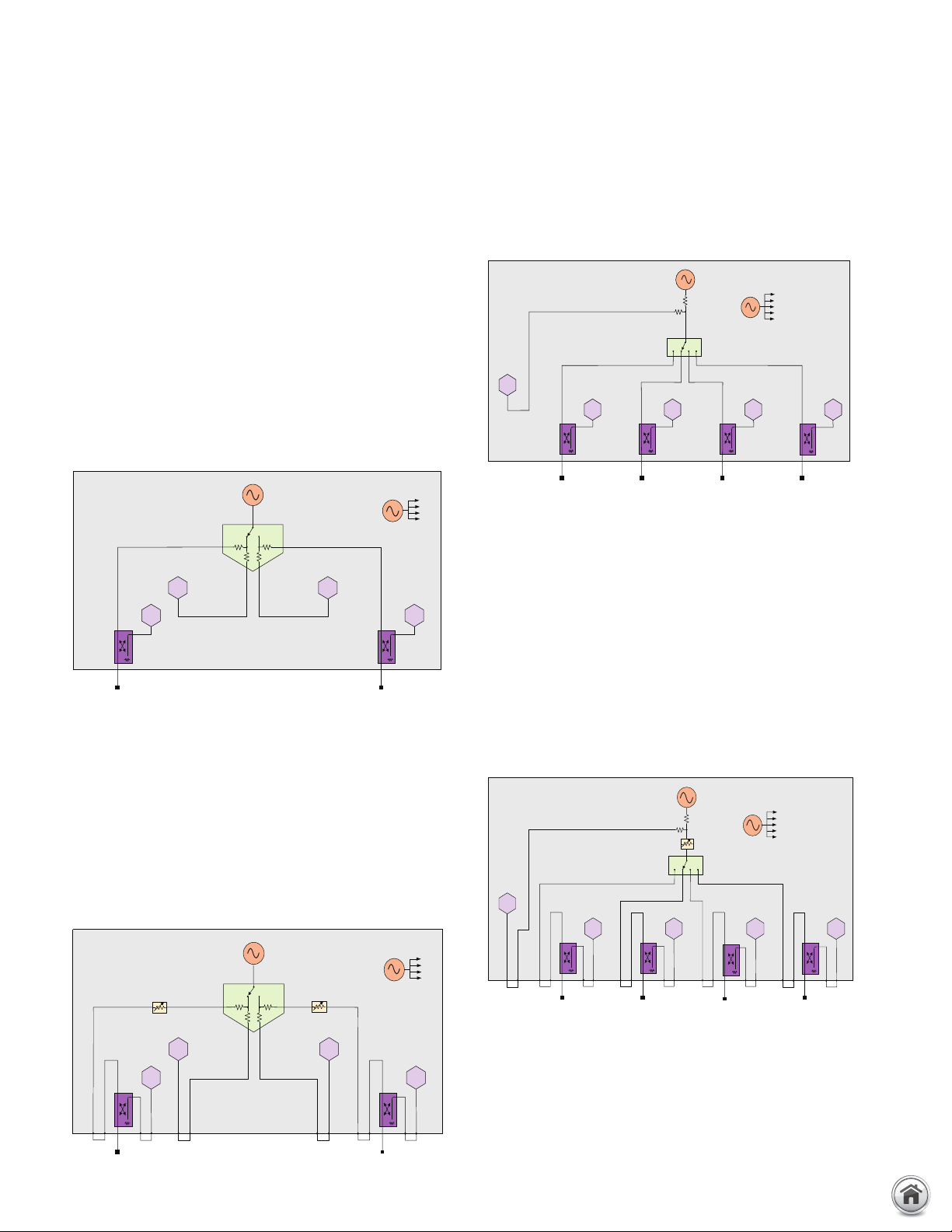
PNA-L Series Test Set and Power Configuration Options
The PNA-L is an integrated vector network analyzer featuring a
built-in S-parameter test set, one synthesized source used for
device stimulus, a solid state drive, USB interfaces, and a 12.1”
LCD touch screen display. The N5239B, N5231B and the N5232B
have 50 ohm, ruggedized 3.5 mm (m) test ports. The N5234A and
N5235B have 50 ohm, ruggedized 2.4 mm (m) test portcluded
with each instrument is a mouse, keyboard (U.S. style). For one
day of on-site productivity assistance (not included with instrument purchase), request quantity 1 each PS-S20-PNA.
A test set and power configuration option is mandatory. Choose
one of the following:
2 ports, single source, base configuration
(Option 200)
The 2-port with base configuration has no front-panel access loops.
2 ports, single source, with configurable test set
and source attenuators (Option 216)
The 2-port test set comes with a configurable test set and source
attenuator at each por t. The configurable test set adds six frontpanel access loops. The loops provide access to the signal path
between (a) the source output and the reference receiver, (b) the
source output and directional coupler thru arm, and (c) the coupled
arm of the directional coupler and the port receiver at all ports.
The source attenuators are settable in 10 dB steps up to 60 dB.
4 ports, single source, base configuration
(Option 400)
The 4-port base configuration has no front-panel loops, and is
available only on the N5231B and N5232B.
4 ports, single source, with configurable test set
and source attenuator (Option 416)
The 4-port test set comes with a configurable test set and one
source attenuator to be shared with all ports. The configurable
test set adds nine front-panel access loops. The loops provide
access to the signal path between (a) the source output and the
reference receiver, (b) the source output and directional coupler
thru arm at all ports, and (c) the coupled arm of the directional
coupler and the port receiver at all ports. The source attenuator
is settable in 10 dB steps up to 60 dB. This configuration is
available only on the N5231B and N5232B.
www.keysight.com/find/pna
Page 18

18 | Keysight | PNA Family Microwave Network Analyzers - Configuration Guide
PNA Family Applications and Options
Measurement application software
Solid black series name indicates the feature is available on that
series, while gray series name with strikethrough indicates the
feature is not available on that series. For example:
PNA: Available on PNA Series
PNA: Not available on PNA Series
Automatic fixture removal (S93007A)
PNA-X PNA PNA-L
Many devices do not have coaxial connectors and are put in fixtures
in order to measure them in a coaxial environment. Accurately
removing the effects of the fix ture is required to get a good
measurement of the device under test (DUT). This application adds
a powerful application wizard to guide you through characterizing
a fixture and removing it from the measurement. Devices can
be single ended or differential. Files can be saved in a variety of
formats for later use in PNA, ADS, and PLTS.
Time domain analysis (S93010A)
PNA-X PNA PNA-L
This application enables the analyzer to view reflection and transmission responses in time or distance. Use time domain to tune
filters, gate out the response of fix tures and cables, characterize
the impedance of transmission lines and more. If eye-diagram
analysis, W-element modeling or high-speed interconnect testing
is required, PLTS N1930B software must be used.
Enhanced time domain analysis with TDR
(S9 3011A)
PNA-X PNA PNA-L
This application enables the analyzer to perform enhanced time
domain analysis for high-speed data applications. All
functionality of the S93010A are included (TDR/TDT mode). In
addition, the S93011A enables more detailed measurements and
evaluations, such as eye-diagram/mask modes, without adding
PLTS software. Jitters and/or emphasis/equalization capabilities
enables simulation of real-world signals and environment. The
S93011A covers up to 67 GHz bandwidth with 6.66 psec rise
time. Full calibration is available and the automatic deskew
ensures easy removal of fixture and probe effects. To get the
best accuracy, mechanical calibration kits or E-cal with DC
option are recommended. S93011A does not work with low
frequency extension option (LFE) enabled on N5222B/27B-205
and N5242B/45B/47B -42 5.
Dynamic uncertainty for S-parameter measurements (S93015A)
PNA-X PNA PNA-L
This enables the analyzer to display the measurement
uncertainty dynamically (real-time) on the same screen as the
measurement trace and get more reliable uncertainty estimation.
Uncertainty of a calibration standard, noise in measurements,
cable, and connector repeatability are included and this function
is compatible with the current Keysight Uncertainty Calculator.
Frequency offset measurements (S93080A)
PNA-X PNA PNA-L
This application enables the analyzer to set the frequency of
the internal sources independently from where the receivers
are tuned, and is required to configure an ex ternal source using
External Device Configuration. This ability is important for
measuring amplifiers, mixers, and frequency converters. The
functionality provided by S93080A is also included with S93029/
082/083/084/086/087/089/090x/093/094A or S94510/511A.
Scalar mixer/converter measurements (S93082A)
PNA-X PNA PNA-L
With a simple setup and calibration, this application delivers the
highest accuracy for scalar conversion-loss/gain measurements
by combining one-port and power-meter calibrations to remove
mismatch errors. S93082A provides an intuitive and easy-to-use
user interface for setting up mixer and converter measurements,
with single or dual conversion stages. It can control the analyzer’s
built-in source(s) as well as external signal generators for use as
LO signals. Supported external sources include the Keysight ESG,
PSG, EXG, and MXG Series, as well as other SCPI-controlled signal generators. S93082A is a subset of S93083A, so they should
not be installed together. S93082A is compatible with S93084A,
which enables measurements of converters with internal LOs.
1. When a comb generator is used as a phase reference for calibration and
the start frequency of the measurement is less than 55 MHz, a usersupplied calibration mixer is required. For measurements between
50 GHz and 67 GHz, an additional high-pass filter is required (two backto-back Keysight V281A waveguide-to-coax adapters recommended;
must be ordered separately).
www.keysight.com/find/pna
Page 19

19 | Keysight | PNA Family Microwave Network Analyzers - Configuration Guide
PNA Family Applications and Options (continued)
Vector and scalar mixer/converter measurements
(S93083A)
PNA-X PNA PNA-L
This application includes the scalar mixer/converter plus phase
(SMC+Phase) measurement class that provides fully calibrated
conversion gain/loss, relative phase, and absolute group delay
measurements of mixers and converters without the need for
reference or calibration mixers. Eliminating the calibration
mixer requires a U9391C/F/G comb generator1 and an external
DC power supply capable of sourcing +15 V and 300 mA for
U9391C/F or 800 mA for U9391G. A vector mixer/converter
measurement (VMC) class is also included for measuring the
phase dif ference between multiple paths or devices, or for
measuring phase shif ts within a device. Using VMC or the combgenerator-based calibration for SMC+Phase requires an instrument with a configurable test set (i.e., has front-panel RF loops).
For units without front-panel loops, SMC+Phase can be used with
a calibration mixer supplied by the user. S93083A provides an
intuitive and easy-to-use user interface for setting up mixer and
converter measurements, with single or dual conversion stages.
It can control the analyzer’s built-in source(s) as well as external
signal generators for use as LO signals. Supported external
sources include the Keysight ESG, PSG, EXG, and MXG Series,
as well as other SCPI-controlled signal generators. S93083A is
a superset of S93082A, so they should not be installed together.
S93083A is compatible with S93084A, which enables measure-
ments of converters with internal LOs.
Embedded LO capability (S93084A)
PNA-X PNA PNA-L
This application tunes the analyzer’s receivers to the output
frequency of the converter under test without the need for
access to internal LOs or a common reference signal. S93084A is
intended to work with S93029/082/083/086/087A measurement
applications.
Gain compression measurements (S93086A)
PNA-X PNA PNA-L
The gain compression application (GCA) provides input power,
output power, gain, and phase at the compression point of an
amplifier or frequency converter, over a specified frequency
range. GCA's SMART Sweep is very fast and easy-to-use. GCA
also includes a guided calibration that corrects for absolute
power levels, frequency response, and mismatch errors.
Intermodulation distortion measurements (S93087A)
PNA-X PNA PNA-L
The intermodulation distortion (IMD) application makes it very
easy to set up and calibrate swept-IMD measurements of both
amplifiers and frequency converters. It controls the frequency
and power of internal and external sources and tunes the receivers
to the main tones as well as the IMD products in a single measure
ment channel. The user can sweep either the center frequency of
the two stimulus signals, the frequency spacing of the two stimulus
signals about a fixed center frequency, or the power of one or both
stimulus signals or the power of the LO signal. The analyzer can
measure intermodulation distortion products of order 2, 3, 5, 7,
or 9, and can display the associated intercept points. In addition,
an IM Spectrum mode gives a spectrum-analyzer-like display
for confirming or trouble-shooting measurements. Not available
with PNA Options 200, 210, 400 and 410. When configured with a
2-port PNA or 2-port PNA-X with either Option 201, 217, or 219,
an external signal generator and a combiner are required. When
configured with a 4-port PNA or 4-port PNA-X with Option 401,
417, or 419, the two internal sources and an unused test port
coupler configured as a combiner can be used for two-tone IMD
measurements. When configured with PNA-X Option 22x or 42x,
the two internal sources and internal combiner can be used for
two-tone IMD measurements.
Source phase control (S93088A)
PNA-X PNA PNA-L
This application allows users to set calibrated, arbitrary phase
differences between two signal sources. The sources can be the
analyzer’s internal sources or external signal generators routed
through the analyzer’s test set. The phase difference can be
fixed, or swept between two specified phase values. Option 088
also controls the relative power level between the sources using
the receiver-leveling feature. Option 088 is targeted for active-
load control, where the analyzer provides a precise, electronically
settable impedance to the output por t of a device, while gain and
output power are measured. This capability can be combined
with external load-pull software to create traditional load-pull
power contours. Not available with PNA Options 200 and 210.
Differential and I/Q device measurements (S93089A)
PNA-X PNA PNA-L
This application combines source-phase control of multiple
internal or external sources with frequency-offset mode, enabling
simplified test of I/Q modulators/converters and differential
mixers, and harmonic measurements of differential amplifiers.
The phase difference between sources can be fixed (for example,
at 90 or 180 degrees), or swept between two specified phase
values. Providing accurate control of the relative phase between
sources eliminates the need for hybrid couplers and baluns to
create quadrature or differential signals. After achieving the
desired phase alignment, the instrument’s receivers can be tuned
to all frequencies needed to characterize the DUT. On an I/Q
modulator for example, measurements can be made of both the
desired and suppressed conversion bands, along with LO leakage,
harmonics and other spurious signals. Phase sweeps can be used
to determine a DUT’s phase imbalance versus frequency. Users
can specify measurements with individual receivers or multiple
receivers combined with a wide range of mathematical operators.
Power measurements can employ match correction for increased
accuracy. S93089A only works on 4-port PNA or PNA-X models.
www.keysight.com/find/pna
Page 20

20 | Keysight | PNA Family Microwave Network Analyzers - Configuration Guide
PNA Family Applications and Options (continued)
Measurement application software (continued)
Solid black series name indicates the feature is available
on that series, while gray series name with strikethrough indicates
the feature is not available on that series. For example:
PNA: Available on PNA Series
PNA: Not available on PNA Series
Spectrum analysis (S93090xA)
PNA-X PNA PNA-L
The spectrum analyzer (SA) application adds high-performance
microwave spectrum analysis to PNA-X, PNA, and PNA-L Series
network analyzers. With fast stepped-FFT sweeps resulting from
optimized data processing, the SA application provides quick
spurious searches over broad frequency ranges. Simultaneous
spectrum measurements can be done using up to five test and
reference receivers. This multi-channel SA can be used with the
internal swept-signal generators for efficient measurements of
spurious signals emanating from mixers and frequency converters.
The SA application employs source-power and receiver-response
calibration as well as fixture de-embedding, providing in-fixture
and on-wafer spectrum measurements with the highest level
of accuracy. It is recommended to use this option with PNA or
PNA-X instruments with internal receiver attenuators to avoid
receiver compression when measuring large signals. For use with
PNA-L models, test set option 216 or 416 is recommended so that
external attenuators can be connected via the front-panel jumpers
to avoid receiver compression. The upper frequency range of the
SA application is determined by the installed SA license or the
stop frequency of the instrument, whichever is smaller. There are
several frequency choices intended for standalone instruments:
S930900A to 8.5 GHz, S930901A to 13.5 GHz, S930902A to 26.5
GHz, S930904A to 43.5 GHz, S930905A to 50 GHz, and S930907A
to 67 GHz. Intended for use with analyzers configured with
broadband or banded millimeter-wave extenders, several more
choices are available: S930909A to 90 GHz, S93093A to 120 GHz,
and S93094A for frequencies above 120 GHz.
Spectrum analysis, beyond 120 GHz (S93094A)
PNA-X PNA PNA-L
S93094A has all of the capability of the S93090xA spectrum analyzer application, with an upper frequency limit determined solely
by the broadband or banded millimeter-wave frequency extenders
used in the system. With this configuration, the analyzer’s internal
receiver attenuators are not in the receiver paths, so they cannot
be used to reduce signal levels. External attenuators may be
required to avoid compressing the receivers in the millimeter-wave
frequency extenders. When using S93094A for millimeter-wave
spectrum analysis, an N5261/62A or an N5292A millimeter-wave
controller is required. When S93094A is installed on a standalone
network analyzer, it will provide spectrum analysis up to the
frequency limit of the instrument.
Active hot parameters (S93110A/S93111A)
PNA-X PNA PNA-L
Active hot parameters allows the PNA-X Series a more accurate
method for testing Hot S-parameter, gain and output power than
traditional methods by utilizing the X-parameter technology.
It removes active device and system interaction to precisely
calculate the active parameters and output power into a nominal
50 Ω environment. The advanced theory removes system-tosystem correlation problems. It also provides coefficients of
equation to calculate linear and non-linear device performance
of gamma-opt (optimum), optimal load match and maximum
delivered power to optimum load. Total 14 traces (parameters)
are available with various sweep types, such as frequency sweep,
power sweep, or two-dimensional frequency and power sweep.
Requires 4-port option configuration 401, 417, 419, 422, 423 or
425. LFE function is not available when using on Option 425.
S93110A is export-controlled and operates up to the PNA-X’s
highest frequency. S93111A is not export-controlled and operates
up to 50 GHz on the N5247B.
True-mode stimulus (S93460A)
PNA-X PNA PNA-L
Spectrum analysis, up to 120 GHz (S93093A)
PNA-X PNA PNA-L
S93093A has all of the capability of the S93090xA spectrum
analyzer application, with an upper frequency of 120 GHz. It is
intended for analyzers configured with broadband or banded
millimeter-wave frequency extenders, using a millimeter-wave
controller. With this configuration, the analyzer’s internal receiver
attenuators are not in the receiver paths, so they cannot be used
to reduce signal levels. External attenuators may be required to
avoid compressing the receivers in the millimeter-wave frequency
extenders. When using S93093A for millimeter-wave spectrum
analysis, an N5261/62A or an N5292A millimeter-wave controller
is required. When S93093A is installed on a standalone network
analyzer, it will provide spectrum analysis up to the frequency limit
of the instrument.
S93460A provides mismatch-corrected true-mode (true differential mode and true common mode) stimulus and enables accurate
balanced measurements under real operating conditions. It also
provides balanced measurements with forward-only sweeps,
reverse-only sweeps, and frequency or power sweeps with
arbitrary phase and amplitude offsets. S93460A only works on
4-port PNA or PNA-X models.
1. When configuring N524xB as a multipor t analyzer using S93551A and a
multiport test set, the combiner feature of Option 22x or 42x is temporarily
disabled. When configured as a standalone analyzer, the combiner feature
is enabled. When ordering a test set, select an appropriate interface kit.
Refer to page 28 Multiport Measurements section for more details.
www.keysight.com/find/pna
Page 21

21 | Keysight | PNA Family Microwave Network Analyzers - Configuration Guide
PNA Family Applications and Options (continued)
Measurement application software (continued)
N-port measurements (S93551A)
PNA-X PNA PNA-L
SS93551A adds a multiport analyzer mode, which enables full
N-port error correction and measurement capabilities using
an external test set. Only the standard measurement class is
available in the multiport analyzer mode. Not available with PNA
Options 200, 210, 400 and 410. For multiport analysis greater
than 8 ports, it is highly recommended to use N1930B PLTS
software to manage the large data files that grow exponentially
(12 port S-parameter files have 144 S-parameter elements).
1
Noise figure options and applications
Add low-noise receiver (Option 029)
PNA-X PNA PNA-L
This option adds a low-noise receiver to the PNA-X to provide
wideband noise figure and noise-power measurements on
a broad range of devices. The noise receiver has three gain
settings, and contains the necessary filters to eliminate
out-of-band noise conversion. For N5241/42/49B instruments,
Option 029 adds a mechanical switch at port one to allow use
of an external ECal module as an impedance tuner to provide
high-accuracy noise figure measurements. For N5244/45/47B
instruments, Option 029 adds a built-in impedance tuner at port
one with a bypass switch. The noise receiver start frequency is
10 MHz and for N5241/42/44/45/49B instruments, it works up to
the stop frequency of the instrument. For N5247B instruments,
the low-noise receiver and tuner work up to 50 GHz only. For
noise figure measurements between 50 and 67 GHz, any of the
standard network analyzer receivers can be used. Option 029 is
intended for use with S93029A sof tware. Without the software,
the noise hardware cannot be utilized.
If S93029A is used on a PNA-X configured with Option 029, then
it makes full use of the built-in low-noise receiver. Optionally,
noise figure measurements can be made using the standard
receivers for high-gain (> 60 dB), narrowband devices that
might otherwise overload the low-noise receiver, or for noise
figure measurements between 50 and 67 GHz on the N5247B. If
running on a PNA, a PNA-X without Option 029, or for measurements up to 67 GHz, then the instrument’s standard receivers
are used. For those cases, an external preamplifier and filter(s) is
required for devices with < 30 dB of excess noise (gain plus noise
figure in dB) up to 20 GHz, < 40 dB up to 50 GHz, or < 45 dB up to
67 GHz. Instruments with front panel jumpers are recommended
as they provide a convenient spot for adding a preamplifier and
filter for low-gain, low-noise-figure devices. S93029A controls
Keysight N46902 Series ECal modules configured as impedance
tuners for use with N522xB PNA models or N5241/42/49B PNA-X
models, or a built-in tuner for N5244/45/47B PNA-X models with
Option 029.
For calibration, a standard mechanical cal kit or ECal module is
required for the S-parameter portion of the cal (an ECal used as a
tuner cannot be shared for calibration). To calibrate the low-noise
receiver, either a noise source (346C or 346C-K01 recommended)
or power meter is required. To calibrate a standard receiver
for noise figure measurements, a power meter is required. For
measurements of mixers and converters, a power meter is always
required, independent of whether a noise source or power meter
is used to calibrate the noise receiver. All calibration accessories
must be ordered separately.
Noise figure measurements with vector correction
(S93029A)
PNA-X PNA PNA-L
This sof tware application enables high-accuracy noise figure and
noise-power measurements of amplifiers, frequency converters,
and mixers, utilizing Keysight’s unique vector-source-correction
technique that uses a source-impedance tuner to remove the
effects of imperfect system-source match. This approach yields
accuracy that surpasses that provided by the Y-factor method
and other cold-source implementations, especially for in-fixture,
on-wafer, and automated-test environments. A scalar-calibrated
method is also available that offers less accuracy, but is faster
and does not require an impedance tuner.
1. When configuring N524xB as a multipor t analyzer using S93551A and a
multiport test set, the combiner feature of Option 22x or 42x is temporarily disabled. When configured as a standalone analyzer, the combiner
feature is enabled. When ordering a test set, select an appropriate
interface kit. Refer to page 28 Multiport Measurements section for more
details.
2. 85090 or N4430 Series ECal modules are not suppor ted
www.keysight.com/find/pna
Page 22
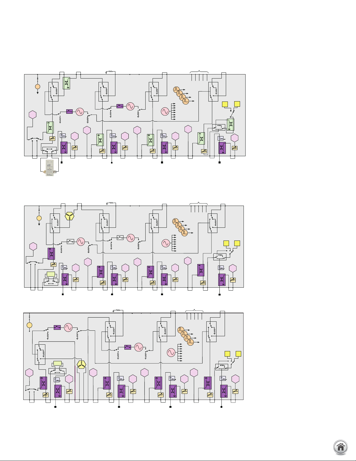
22 | Keysight | PNA Family Microwave Network Analyzers - Configuration Guide
C
R3
Test port 1
R1
Test port 4
R4
A
D
Rear panel
Pulse generators
1
2
3
4
Source 1
OUT 1 OUT 2
Pulse
modulator
Source 2
OUT 1 OUT 2
Pulse
modulator
Test port 2
R2
B
Noise receiver
10 MHz -
6 GHz
6-8.5/
13.5/
26.5 GHz
To receivers
LO
+28 V
Test port 3
Signal
combiner
+
-
Impedance tuner for noise
figure measurements
J9J10J11 J8 J7 J2 J1J4 J3
35 dB 35 dB 35 dB
35 dB
65 dB
65 dB
65 dB
65 dB
J6 J5
RF
OUT
LO
OUT
R A B C D
IF inputs
IF inputs
PNA Family Applications and Options (continued)
PNA-X block diagrams with noise figure option
N5241/42 /4 9B 4- po r t
block diagram with
noise figure option
1
Rear panel
+28V
+
-
OUT 1 OUT 2
R1
60 dB
Tuner
Rear panel+28 V
+
-
R1
50 dB 50 dB 50 dB 50 dB
Test port 1
1. S93029A software is required to control the impedance tuner and tuner switch at por t one, and the noise
receiver and noise switch at por t two
Source 1
OUT 1
Pulse
modulator
Tuner
J9J10J11 J8 J7 J2 J1J4 J3
Signal
combiner
Source 1
Pulse
modulator
OUT 1 OUT 2
R3
A
35 dB 35 dB 35 dB
60 dB
Test port 1
OUT 2
R3
Test port 3
Signal
combiner
A
50
dB
J6 J5
RF
LO
OUT
OUT
Source 2
Pulse
modulator
R4
C
Test port 3
J12 J6 J5J7 J2 J1J4 J3
RF2
RF1
OUT
OUT
Source 2
(standard)
OUT 1 OUT 2
Pulse
modulator
C
50 dB
60 dB
LO
OUT
R4
Test port 4
Pulse generators
LO
D
Test port 4
LO
IF inputs
R A B C D
1
2
3
4
To receivers
R2
60 dB
R A B C D
Pulse generators
1
2
To receivers
R2
D
50 dB
3
4
Test port 2
Noise receiver
10 MHz-
50 GHz
6 GHz
B
Test port 2
Noise receivers
10 MHz -
6 GHz
B
6 -43.5/
35 dB
6 -50
GHz
50 dB
N5244/45B 4-port block
diagram with noise
figure option
1
N5247B 4-port block
diagram with noise
figure option
1
www.keysight.com/find/pna
Page 23

23 | Keysight | PNA Family Microwave Network Analyzers - Configuration Guide
PNA Family Applications and Options (continued)
Noise figure measurement summary
Overview S93029A without Option 029 S93029A with Option 029
Description Noise gure application using standard receivers only, for all
PNA/PNA-X models.
Required options Not recommended with PNA Options 200, 210, 400, 410. For N5241/42/49B, one of Options 21x, 22x, 41x or 42x.
Includes low-noise receiver No Yes
Includes lters for LO-harmonic
No Yes
rejection
Includes source tuner bypass switch No Yes
Use standard receivers for noise
gure measurements
2
Vector noise calibration available
Yes Yes
Yes Yes
using ECal as tuner
Vector noise calibration using built-in tuner No Yes, for N5244/45/47B
Recommended ECal for vector
noise calibration
3
3.5 mm N4691B-M0F (N5221/22/41/42/49B)
2.4 mm N4693A-M0F (N5224/25/44/45B)
1.85 mm N4694A-M0F (N5227/47B)
Included tuner accessories for m-f ECal 3.5 mm N5242-20137 cable, 85052-60013 m-f adapter
(N5221/22/41/42/49B)
2.4 mm N5245-20140 cable, 85056-60007 m-f adapter
(N5224/25/44/45B)
1.85 mm N5247-20142 cable, 85058-60115 m-f adapter
(N5227/47B)
Recommended adapter for f-f ECal tuner
(N4691B/93A/94A-00F)
3.5 mm 85052-60014 m-m adapter (N5221/22/41/42/49B)
2.4 mm 85056-60005 m-m adapter (N5224/25/44/45B)
1.85 mm 85058-60113 m-m adapter (N5227/47B)
Scalar noise calibration available Yes Yes
S-parameter, conversion gain/loss
measurements
Max freq (GHz) 8.5/13.5/26.5/43.5/50/67 8.5/13.5/26.5/43.5/50/67
NF measurements, amplifiers
Max frequency, using low-noise
receivers (GHz)
Max frequency, using standard
receivers (GHz)
2
Calibration accessories for low-noise
receivers
Calibration accessories for standard
receivers
N/A 8.5/13.5/26.5/43.5/50
8.5/13.5/26.5/43.5/50/67 8.5/13.5/26.5/43.5/50
N/A Cal kit or ECal, 346C or 346C-K01 noise source or power meter
Cal kit or ECal, power meter Cal kit or ECal, power meter
NF measurements, converters
Max DUT input frequency (GHz) 8.5/13.5/26.5/43.5/50/67 8.5/13.5/26.5/43.5/50/67
Max DUT output frequency, using low-noise
receivers (GHz)
Max DUT output frequency, using standard
receivers (GHz)
2
Calibration accessories for low-noise
receivers
Calibration accessories for standard receivers Cal kit or ECal, power meter Cal kit or ECal, power meter
N/A 8.5/13.5/26.5/43.5/50
8.5/13.5/26.5/43.5/50/67 8.5/13.5/26.5/43.5/50/67
N/A Cal kit or ECal, power meter, 346C or 346C-K01 noise source
Noise gure application using standard or low-noise receivers, for
all PNA-X models.
For N5244/45/47B, one of Options 22x or 42x.
1
1
1
3.5 mm N4691B-M0F (N5241/42/49B)
Built-in for N5244/45/47B
3.5 mm N5242-20137 cable, 85052-60013 m-f adapter
(N5241/42/49B)
N/A for N5244/45B, due to built-in tuner
1.85 mm N5247-20142 cable, 85058-60115 m-f adapter
(N5247B, for use with external 67 GHz ECal)
3.5 mm 85052-60014 m-m adapter (N5241/42/49B)
N/A for N5244/45/47B, due to built-in tuner
(optional)
1. For N5247B, the low-noise receiver and tuner works up to 50 GHz only.
2. External preamplifier and filter(s) required if DUT excess noise (gain plus noise figure) is < 30 dB up to 20 GHz, < 40 dB up to 50 GHz, or < 45 dB up to 67 GHz.
3. Only N4690 Series ECal modules are supported for use as an impedance tuner.
www.keysight.com/find/pna
Page 24
24 | Keysight | PNA Family Microwave Network Analyzers - Configuration Guide
1 2 3 4 5 6 7 8
9 01 11 21 31 41 51
PNA Family Applications and Options (continued)
Pulse, antenna, mm-wave applications and
options
Solid black series name indicates the feature is available on
that series, while gray series name with strikethrough
indicates the feature is not available on that series. For
example:
PNA: Available on PNA Series
PNA: Not available on PNA Series
Basic pulsed-RF measurements (S93025A)
PNA-X PNA PNA-L
This application enables four internal pulse generators
that can be used to control the internal pulse modulators
(Options 021 and 022), and it provides an integrated pulse
application that uses the wideband-detection method. The
pulse application provides an easy way to set up point-inpulse measurements with pulse width as narrow as 200
ns, and pulse-profile measurements with 50 ns minimum
timing resolution. Using the built-in pulse modulators, the
PNA and PNA-X are complete pulsed-RF measurement
solutions, eliminating the need for external test sets and
pulse generators. S93025A also controls external pulse
generators and modulators, and can synchronize to
external master pulses. Option 021 is recommended for
forward-only pulsed-RF measurements, and Options 021
and 022 are recommended for bi-directional pulsed-RF
measurements. The N1966A Pulse I/O adapter is recommended if using external master pulses or external pulse
modulators.
Pulse I/O D-sub connector (DB-15 female)
recommended for forward-only pulsed-RF measurements,
and Options 021 and 022 are recommended for bi-directional
pulsed-RF measurements. The N1966A Pulse I/O adapter is
recommended if using external master pulses or external pulse
modulators.
Add pulse modulator to internal first source
(Option 021) PNA-X PNA PNA-L
This option enables the internal pulse modulator on Source1
Out1. Control of the modulator can be done via pin 8 of the Pulse
I/O D-sub connector on the rear panel of the analyzer using an
external pulse generator, or by using one of the internal pulse
generators enabled with S93025/26A. The N1966A pulse I/O
adapter is recommended if using an external pulse generator.
Add pulse modulator to internal second source
(Option 022) PNA-X PNA PNA-L
This option enables the internal pulse modulator on Source2
Out1. Control of the modulator can be done via pin 8 of the Pulse
I/O D-sub connector on the rear panel of the analyzer using an
external pulse generator, or by using one of the internal pulse
generators enabled with S93025/26A. The N1966A pulse I/O
adapter is recommended if using an external pulse generator.
Requires one of text set options 22x or 4xx.
Add IF inputs for antenna and millimeter-wave
(Option 020) PNA-X PNA PNA-L
This option enables external IF inputs on the rear panel
of the analyzer for applications such as antenna test and for
use with millimeter-wave test set controllers (for more information about millimeter-wave network analyzer configurations,
see Millimeter-Wave Network Analyzers Technical Overview,
598 9 -7620EN).
Advanced pulsed-RF measurements
(S93026A) PNA-X PNA PNA-L
This application includes all of the capability of S93025A
(including enabling the four internal pulse generators), and
adds the narrowband-pulse-detection method to extend
pulse measurement capability to 20 ns pulse widths for
point-in-pulse measurements, and 10 ns timing resolution
for pulse-profile measurements. With narrowbanddetection mode, S93026A sets the coef ficient of the
analyzer’s digital-IF filters to null out unwanted spectral
components, enables the receiver IF gates, and performs
optimization for measurement sensitivity. Using the built-in
pulse modulators, the PNA and PNA-X are complete
pulsed-RF measurement solutions, eliminating the need
for external test sets and pulse generators. S93026A also
controls external pulse generators and modulators, and
can synchronize to external master pulses. Option 021 is
Fast CW sweep (Option 118)
PNA-X PNA PNA-L
This option uses a FIFO (first-in first-out) buffer to allow external
point-trigger acquisition of 400,000 data points per second on five
measurement receivers. When enabled, there is no display update,
no background computation, or other interference from the vector
network analyzer application. All the data gathered is placed into
a 500-million-point FIFO buffer. Data may be read from the FIFO
buffer at the same time as it is filled.
Nonlinear vector network analysis
Please refer to 5989-8575EN Nonlinear Vector Network
Analyzer Brochure for more information.
www.keysight.com/find/pna
Page 25
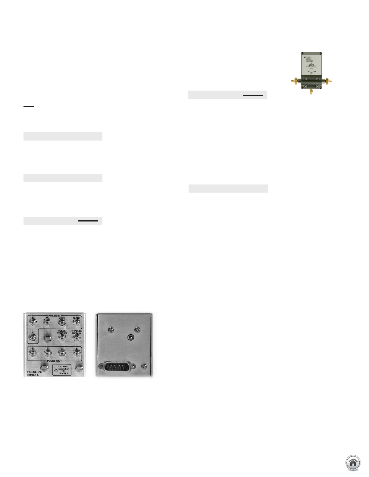
25 | Keysight | PNA Family Microwave Network Analyzers - Configuration Guide
PNA Family Applications and Options (continued)
Accessories
Solid black series name indicates the feature is available on that
series, while gray series name with strikethrough indicates the
feature is not available on that series. For example:
PNA: Available on PNA Series
PNA: Not available on PNA Series
Rack mount kit without handles (Option 1CM)
PNA-X PNA PNA-L
Adds a rack mount flange kit 1CM042A and a rail kit (E3663AC)
for use without handles.
Rack mount kit with handles (Option 1CP)
PNA-X PNA PNA-L
Adds handles (5063-1542), a rack mount flange kit (5063-1572)
and a rail kit (E3663AC) for use with handles.
Pulse I/O adapter (N1966A)
PNA-X PNA PNA-L
This adapter enables coaxial connections between the Pulse I/O D-sub
connector on the rear panel of the analyzer and the coaxial inputs and
outputs of external pulse generators and external pulse modulators. Coaxial
connectors are SMB-male. The PULSE IN connectors are for controlling the
analyzer’s internal IF gates, which are enabled with S93026A and used with
narrowband detection. The PULSE OUT connectors are from the four internal
pulse generators, which are enabled with S93025/26A. The PULSE SYNC IN
connector is used to synchronize the internal pulse generators with an
external timing pulse. The RF PULSE MOD IN connector controls the internal
pulse modulator(s) which are enabled with Options 021 and 022.
Comb Generators
U9391C 10 MHz to 26.5 GHz
U9391F 10 MHz to 50 GHz
U9391G 10 MHz to 67 GHz
PNA-X PNA PNA-L
The U9391C/F/G provides precision phase calibration, traceable
to the National Institute of Standards and Technology (NIST)
standard. It is used for nonlinear measurements with the PNA-X
nonlinear vector network analyzer (NVNA). NVNA requires two
comb generators, one is connected during measurements and
another is used only during calibration. A comb generator is also
used to characterize the VNA receivers for delay measurements
of frequency converters using PNA-X or PNA instruments and the
SMC+Phase measurement class (part of S93083A).
CalPod calibration refresh modules (8553xB/4xA)
PNA-X PNA PNA-L
CalPod calibration refresh modules allow in-situ calibration
refreshes to be performed at the push of a button without removing the DUT or re-connecting calibration standards. CalPods
are designed for any measurement situation where it is desirable
to ensure that a valid calibration is present before recording
measurement data. For example, they are useful for removing
environmental effects such as cable movement and thermalbased changes of cables, connectors, and adapters, as well as
connector and switch-matrix repeatability errors. The modules
are especially useful in temperature, or thermal-vacuum chamber
testing. CalPod modules are equipped with 2.92 mm connectors.
– 85530B 20 GHz ambient-temperature CalPod
– 85531B 20 GHz temperature-compensated CalPod
– 85532B 20 GHz thermal-vacuum compatible CalPod
– 85540A 40 GHz ambient-temperature CalPod
– 85541A 40 GHz temperature-compensated CalPod
– 85542A 40 GHz thermal-vacuum compatible CalPod
– 85523B CalPod controller (provides control for up to 4
CalPods)
– 85556A CalPod drive-cable splitter (allows control for up to
12 CalPods)
– 85554A CalPod drive cable extension (10-meter cascadable
extension cable)
Pulse I/O adapter (N1966A) simplifies connections
www.keysight.com/find/pna
Page 26

26 | Keysight | PNA Family Microwave Network Analyzers - Configuration Guide
PNA Family Network Analyzer Upgrade Kits
Frequency, test ports, test set and power configurations
Upgrade kits are available to add options after initial purchase. To upgrade the PNA-X/PNA/PNA-L, order the corresponding item
number. The model and serial numbers of the instrument to be retrofitted are required as part of the order. To add application software, order the appropriate standalone model numbers shown in the tables on pages 6 and 7.
For PNA-X
Description Required Option
Frequency upgrade
Extend analyzer's frequency range to 13.5 GHz N5239/49B N5249BU-613 n/a N5239BU-613 No
Extend analyzer's frequency range to 20 GHz N5231/39B n/a n/a N5231/39BU-620 No
Extend analyzer's frequency range to 26.5 GHz N5221/41/49B N5241/49BU-626 N5221BU-626 n/a No
Extend analyzer's frequency range to 50 GHz N5224/34/44B N5244BU-650 N5224BU-650 N5234BU-650 No
1
Series
Test ports
Expand 2-ports, single source without congurable test
set to 4-ports
Expand 2-ports, single source with congurable test set
to 4-ports
Expand 2-ports, single source with congurable test set
and extended power range to 4-ports
Expand 2-ports, single source with congurable test set,
extended power range, and bias-tees to 4-ports
Expand 2-ports, internal second source with congurable
test set, extended power range, combiner, and mechanical
switches to 4-ports
Expand 2-ports, internal second source with congurable
test set, extended power range, bias-tees, combiner, and
mechanical switches to 4-ports
N522xB-200 n/a N522xBU-600 n/a No
N522x/4xB-201 N524xBU-601 N522xBU-601 n/a No
N522x/4xB-217 N524xBU-617 N522xBU-617 n/a No
N522x/4xB-219 N524xBU-619 N522xBU-619 n/a No
N524xB-222 N524xBU-622 n/a n/a No
N524xB-224 N524xBU-623 n/a n/a No
Test set and power conguration
Add congurable test set, 2-ports N522xB-200 n/a N522xBU-201 n/a No
Add congurable test set and source attenuators, 2-ports N523xB-200 n/a n/a N523xBU-216 No
Add low frequency extension, 2-ports N5222/27B-201 n/a N5222/27BU-205 n/a No
Add extended power range, 2-ports
Add bias-tees, 2-ports
Add internal 2nd source, combiner and mechanical
switches, 2-ports
Add congurable test set, 4-ports N522xB-400 n/a N522xBU-401 n/a No
Add congurable test set and source attenuators, 4-ports N523xB-400 n/a n/a N523xBU-416 No
Add extended power range, 4-ports
Add bias-tees, 4-ports
Add internal combiner and mechanical switches, 4-ports N524xB-417/419 N524xBU-423 n/a n/a No
Add low frequency extension, 4-ports N5242/45/47B-423 N5242/45/47BU-4254n/a n/a No
Add low-noise receiver, 2-ports N524xB-20x, 21x, 22x N524xBU-229 n/a n/a No
Add low-noise receiver, 4-ports N524xB-40x, 41x, 42x N524xBU-429 n/a n/a No
2
2
2
2
N522x/4xB-201 N524xBU-217 N522xBU-217 n/a No
N522x/4xB-217 or N524xB-222 N524xBU-219 N522xBU-219 n/a No
N524xB-217/219 N524xBU-224 n/a n/a No
N522x/4xB-401 N524xBU-417 N522xBU-417 n/a No
N522x/4xB-417 or N524xB-422 N524xBU-419 N522xBU-419 n/a No
Pulse, antenna, mm-wave
Add pulse modulator to internal 1st source N524xBU-021 N522xBU-021 n/a Yes
Add pulse modulator to internal 2nd source Requires one of Options 22x, 40x,
41x, or 42x
Add IF inputs N524xBU-020 N522xBU-020 n/a Yes
N524xBU-022 N522xBU-022 n/a Yes
A to B model upgrades
The A to B model upgrade kit includes a new front-panel assembly with 12.1” multi-touch
display, a new solid-state hard drive, and a new instrument cover and handles with Keysight’s
dark-gray color scheme3.
1. Frequency upgrade options from 8.5/13.5/20/26.5 GHz to 43.5/50 GHz and 43.5/50 GHz to 67 GHz are not available. Trade-in is recommended.
2. Not available on N5227/47B.
3. May also require update of CPU, SPAM, and synthesizer assemblies, supplied in separate upgrade kits. For more information, visit na.support.keysight.com/pna
4. Cannot order N5245BU-425 if the base unit already has N5245B-029 installed.
N524xAU-690 N522xAU-690 N523xAU-690 No
For PNA
Series
For PNA-L
Series
User
Installable
www.keysight.com/find/pna
Page 27

27 | Keysight | PNA Family Microwave Network Analyzers - Configuration Guide
PNA-X upgrade path
Frequency
N5241BU-626
N5244BU-650
201
217
219
217
219
229
1
401
417
419
417
419
429
1
601
617
619
2-ports 4-ports
217/029
219/029
417/029
419/029
419
1
219
1
229
1
429
1
H
N5249BU-613
N5249BU-626
13.5 GHz
26.5 GHz
43.5 GHz
50 GHz
67 GHz
8 5G z
.
H
422/029
423/029
419
423
1
423
1
423
419
422
224
219
222
222/029
224/029
219
224
1
224
1
622
623
229
224
224
229
429
429
423
423
425/029
425
425
2
425
4
429
4
PNA upgrade path
Frequency
13.5 GHz
26.5 GHz
43.5 GHz
50 GHz
67 GHz
N5221BU-626
N5224BU-650
200
201
217
219
201
217
219
400
401
417
419
401
417
419
600
601
617
619
2-ports 4-ports
205
3
205
PNA Family Network Analyzer Upgrade Kits (continued)
Upgrade paths
1. This upgrade path only available for N5241/42/49B.
2. This upgrade path only available for N5242B, N5245B, and N5247B.
3. This upgrade path only available for N5222/27B.
4. This upgrade path only available for N5242B and N5247B.
8.5 GHz
13.5 GHz
20 GHz
Frequency
N5239BU-613
N5231BU-620
N5239BU-620
PNA-L upgrade path
43.5 GHz
50 GHz
N5234BU-650
2-ports
200
216
216
4-ports
400
416
416
www.keysight.com/find/pna
Page 28

28 | Keysight | PNA Family Microwave Network Analyzers - Configuration Guide
Applications
Material measurements
The Keysight N1500A materials measurement suite streamlines
the process of measuring complex permittivity and permeability
with a network analyzer. Various type of measurements, such
as transmission line and free space, arch reflectivity, resonant
cavity, and coaxial probe are available as options. The easy-touse software guides the user through setup and measurement,
instantly converting S-parameter network analyzer data into
the data format of your choice and displaying the results within
seconds. Results can be charted in a variety of formats: ε
tanδ, µ
, µ
, tanδµ, and Cole-Cole.
r
r
’
”
, ε
,
r
r
’
”
Signal integrity measurements
N1930B Physical Layer Test System (PLTS) Sof tware
The PLTS sof tware platform has become an industry standard for
calibration, measurement, and analysis of linear passive interconnects such as cables, connectors, backplanes, and printed circuit
boards. Utilizing either a vector network analyzer (VNA) or a time
domain reflectometer (TDR), fast and accurate measurements
can be obtained without in-depth knowledge of microwave
measurement techniques. Refer to www.keysight.com/find/plts
or the technical overview (literature number 5989-6841EN) for
more details.
Multiport measurements
Multiport test sets are designed to work with the PNA family
of network analyzers to provide a single set of connections to
devices with more than four ports. Test sets come with different
port counts and frequency ranges, and are built to work with
2- or 4-port network analyzers. They are configured as switching
or extension test sets, using electro-mechanical or solid-state
switches.
Test set types: switching and extension
Switching test sets provide an economical solution for RF
applications. They are connected directly to the test ports of the
VNA, and a group of test ports share the directional couplers
and receivers in the VNA. Extension test sets are connected to
the sources and test receivers through the configurable test
set of the VNA. They feature a directional coupler for every test
port, and all switching occurs behind the directional couplers,
providing the ultimate in flexibility, stability, and performance for
RF and microwave applications.
Switch types: electro-mechanical and
solid-state
Electro-mechanical switches have less insertion loss, higher
power handling, and a more linear response compared to solidstate switches. They are recommended for testing active devices,
high-power devices, and devices that require wide dynamic
range. However, they have limited switching life (mostly 5 million
cycles) and long setting times. In contrast, solid-state switches
have unlimited switching life, very fast switching speed, and
excellent repeatability. Thus, they are often used for high-volume
S-parameter measurements of passive devices.
Test set model number
Multiport test set model numbers represent the type of test set;
note the numbering scheme below.
Note that there are some test sets that do not follow this numbering scheme such as U3022AE10, U3025AE06,
and U3025AE10, which use solid-state switches, and U3022AS66, which includes 1x6 switching test set and six
calibration distribution ports.
www.keysight.com/find/pna
Page 29

29 | Keysight | PNA Family Microwave Network Analyzers - Configuration Guide
Applications (continued)
Test set options
One of the following test set options must be selected.
Standard configuration (Option 700)
– The standard configuration is the basic test set configuration,
which does not include signal conditioning devices such as
amplifiers.
Add amplifiers for improved dynamic range (Option 001)
– Option 001 adds an amplifier between each test port coupler
and the receiver switch to improve system dynamic range. It
is primarily offered for test sets with solid-state switches, to
compensate for insertion loss.
Add amplifiers and bias-tees (Option 002)
– Option 002 adds an amplifier between each test port coupler
and the receiver switch to improve system dynamic range,
and adds bias-tees for all test por ts on the test set as well as
the analyzer. It is primarily of fered for test sets with solidstate switches to compensate for insertion loss.
Millimeter-wave measurements
N5290/91A single-sweep millimeter-wave
solutions
PNA (N522xB) and PNA-X (N524xB) network analyzers can
be transformed into single-sweep solutions that operate from
900 Hz to 110 GHz (N5290A), or up to 120 GHz with over-range
capability to 125 GHz (N5291A). The N5290/91A solutions come
fully configured around the PNA /PNA-X network analyzers,
and include a millimeter-wave test set controller (N5292A),
frequency-extender modules (N5293/95AXxx), and the necessary
cables to allow users to make either 2- or 4-port measurements
over the entire frequency range. The broadband N5290/91A
millimeter-wave solutions provide high-performance measurement capability complimented by measurement applications
from the PNA/PNA-X that include pulsed-RF, gain compression,
4-port true-differential, scalar mixer/converter measurements,
and spectrum analysis.
Interface kits
The interface kit includes a set of semi-rigid RF jumper cables and
two pairs of rear locking feet that connect and lock the analyzer
and the test set together. When ordering a multiport test set, the
analyzer that is used with the test set must be specified to add
one of the following interface kits. The availability depends on
the test set model. There are following three interface kit models
based on the jumper connector layouts on the test set. Therefore,
only one interface kit model (“PX”, “PN”, or “PL”) is available
on each test set. Each interface kit model has one digit suffix
indicating the connector type; 1 for 1.85 mm, 2 for 2.4 mm and 3
for 3.5 mm (or SMA).
U3 021PXx Interface kit for test set with jumper connectors to align
with N524xB PNA-X and N522xB PNA
U3 021PNx Interface kit for test set with jumper connectors to align
with E836xB/C PNA and N5230A/C-x25 2-port PNA-L
U3 021PLx Interface kit for test set with jumper connectors to align
with N523xA /B-416 4-port PNA-L
Option 261 For use with E8361A/C 2-port PNA
Option 262 For use with E8362B/C 2-port PNA, or N5230A/C-225 or
N523xA/B-216 2-port PNA-L
Option 263 For use with E8363B/3C/4B/4C 2-port PNA, or
N5230A/C-425/525 2-port PNA-L
Option 430 For use with N5230A/C-425/426 or N523xA/B-416
Option 242 For use with N5221/22/41/42/49B-2xx 2-port PNA/PNA-X
Option 442 For use with N5221/22/41/42/49B-4xx 4-port PNA/PNA-X
Option 245 For use with N5224/25/44/45B-2xx 2-port PNA/PNA-X
Option 445 For use with N5224/25/44/45B-4xx 4-port PNA/PNA-X
Option 247 For use with N5227/47B-2xx 2-port PNA/PNA-X
Option 447 For use with N5227/47B-4xx 4-port PNA/PNA-X
When ordering an additional cable set, a spare cable or rear locking feet, refer to
the multiport test set user’s guide or go to: www.keysight.com/find/multiport
Banded waveguide solutions to 1.5 THz
Banded waveguide millimeter-wave solutions cover waveguide
bands from 50 GHz to 1.5 THz. A 2- or 4-port PNA or PNA-X in
conjunction with an N5292A millimeter-wave controller (with
either a 2- or 4-port option), provides complete millimeter-wave
solutions. These systems are configured with a PNA or PNA-X
which has IF inputs (Option 020), and a configurable test set
(one of Options 201/217/219/222/224/401/417/419/422/423. In
addition, frequency-offset capability is required from one of software models S93029/080/082/083/084/086/087/089/090x/
093/094A. When configured with the N5292A millimeter-wave
controller, a special cable adapter will be required to connect the
RF, LO, and IF signals from the banded millimeter-wave extenders
to the controller. A separate DC power supply is also required to
power the frequency extenders.
For a complete list of millimeter-wave products and options, and
ordering instructions, please refer to the N5290/91A MillimeterWave Network Analyzer Configuration Guide (5992-2179EN),
and the Banded Millimeter-Wave Network Analyzers to 1.5 THz
Technical Overview (5992-2177EN).
www.keysight.com/find/pna
Page 30

30 | Keysight | PNA Family Microwave Network Analyzers - Configuration Guide
Network analyzer
test set
Network analyzer
test set
Test port
adapter
Device
under
test
Single cable
Device
under
test
Cable set
Measurement Accessories
A complete list of RF and microwave test accessories is available
on our Web site: www.keysight.com/find/mta
Accessories are available in these connector types:
50 Ω Type-N, 3.5 mm, 7 mm, 2.4 mm, 2.92 mm, 1.85 mm, 1.0 mm,
and waveguide. Test port cables and a calibration kit should be
added for a complete measurement system. A verification kit is
used to verify corrected system performance.
Cables and adapter sets
Keysight of fers cables in the following types:
– single cables in semi-rigid and flexible
– cable sets in semi-rigid and flexible
There are also adapter sets available that protect the test port
and convert the port to the desired connector inter face. These
kits contain:
– one male adapter
– one female adapter
To attain the best mechanical rigidity for device connection, use a
single cable and the appropriate special adapter set. To attain the
greatest flexibility for device connection, use a cable set.
Calibration kits
Coaxial measurements
Mechanical calibration kits include standards, such as opens,
shorts and loads, which are measured by the network analyzer for
increased measurement accuracy.
Choose a calibration kit for each connector type to be used.
Economy, includes:
– open standards (male and female)
– short standards (male and female)
– fixed-termination standards (male and female)
Standard, includes the devices in the economy kit and adds:
– sliding load standards (male and female) or a series of of fset
shorts
Precision, includes the devices in the economy kit and adds:
– 50 Ω airline(s) for TRL calibration
– TRL adapters
Electronic calibration (ECal) kits replace mechanical calibration standards with one solid-state calibration module that is
controlled by the network analyzer via USB, to present many
different impedances to the test por ts. A full two-port calibration
can be performed quickly with a single connection. This technique reduces operator errors and connector wear and abrasion.
For more information about ECal modules, refer to the technical
overview 5963-3743E (N4690, 85090, and N4430 Series).
Waveguide measurements
For waveguide measurements, Keysight offers mechanical
calibration kits that include:
– waveguide-to-coax adapters (X, P, K, R, Q, U, V)
– precision waveguide section
– flush short circuit
– fixed terminations
– straight section
www.keysight.com/find/pna
Page 31

31 | Keysight | PNA Family Microwave Network Analyzers - Configuration Guide
For devices with 1.0 mm connectors
Mechanical calibration/verification kit
85059B DC to 120 GHz precision calibration kit.
Includes:
– 85059-60027 1.0 mm (m) short, 1.3 mm
– 85059-60029 1.0 mm (m) short, 2.45 mm
– 85059-60031 1.0 mm (m) short, 3.326 mm
– 85059-60033 1.0 mm (m) short, 4.039 mm
– 85059-60028 1.0 mm (f) short, 1.3 mm
– 85059-60030 1.0 mm (f) short, 2.45 mm
– 85059-60032 1.0 mm (f) short, 3.326 mm
– 85059-60034 1.0 mm (f) short, 4.039 mm
– 85059-60053 1.0 mm (m) open
– 85059-60054 1.0 mm (f) open
– 85059-60019 1.0 mm (m) 50 GHz load
– 85059-60020 1.0 mm (f) 50 GHz load
– 85059-60044 1.0 mm m-m adapter
– 85059-60045 1.0 mm f-f adapter
– 85059-60046 1.0 mm m-f adapter
– 8710-2812 6 mm 4 in-lb torque wrench
– 8710-2813 14 mm 4 in-lb torque wrench
– 8710-2156 6 mm open-end wrench
Cables
– 11500I 1.0 mm (f-f) test port cable (8.8 cm)
– 11500J 1.0 mm (m-f) test port cable (16.0 cm)
– 11500K 1.0 mm (m-f) test port cable (20.0 cm)
– 11500L 1.0 mm (m-f) test port cable (24.0 cm)
For devices with 1.85 mm connectors
Mechanical calibration kit
85058B standard: DC to 67 GHz. Includes:
– 85058-60101 1.85 mm (m) short 5.4 mm
– 85058-60102 1.85 mm (m) short 6.3 mm
– 85058-60103 1.85 mm (m) short 7.12 mm
– 85058-60104 1.85 mm (m) short 7.6 mm
– 85058-60105 1.85 mm (f) short 5.4 mm
– 85058-60106 1.85 mm (f) short 6.3 mm
– 85058-60107 1.85 mm (f) short 7.12 mm
– 85058-60108 1.85 mm (f) short 7.6 mm
– 85058-60109 1.85 mm male open
– 85058-60110 1.85 mm female open
– 85058-60111 1.85 mm male load
– 85058-60112 1.85 mm female load
– 85058-60113 1.85 mm (m) to 1.85 mm (m) adapter
– 85058-60114 1.85 mm (f) to 1.85 mm (f) adapter
– 85058-60115 1.85 mm (m) to 1.85 mm (f) adapter
85058E economy: DC to 67 GHz. Includes:
– 85058-60101 1.85 mm (m) short 5.4 mm
– 85058-60105 1.85 mm (f) short 5.4 mm
– 85058-60109 1.85 mm male open
– 85058-60110 1.85 mm female open
– 85058-60123 1.85 mm male load
1
1
1
– 85058-60124 1.85 mm female load
– 85058-60113 1.85 mm (m) to 1.85 mm (m) adapter
– 85058-60114 1.85 mm (f) to 1.85 mm (f) adapter
– 85058-60115 1.85 mm (m) to 1.85 mm (f) adapter
Adapter set
– V281C 1.0 mm(f) to V-band waveguide adapter
– V281D 1.0 mm (m) to V-band waveguide adapter
– W281C 1.0 mm (f) to W-band waveguide adapter
– W281D 1.0 mm (m) to W-band waveguide adapter
– 11920A 1.0 mm (m) to 1.0 mm (m) adapter
– 11920B 1.0 mm (f) to 1.0 mm (f) adapter
– 11920C 1.0 mm (m) to 1.0 mm (f) adapter
– 11921A 1.0 mm (m) to 1.85 mm (m) adapter
– 11921B 1.0 mm (f) to 1.85 mm (f) adapter
– 11921C 1.0 mm (m) to 1.85 mm (f) adapter
– 11921D 1.0 mm (f) to 1.85 mm (m) adapter
– 11922A 1.0 mm (m) to 2.4 mm (m) adapter
– 11922B 1.0 mm (f) to 2.4 mm (f) adapter
– 11922C 1.0 mm (m) to 2.4 mm (f) adapter
– 11922D 1.0 mm (f) to 2.4 mm (m) adapter
– 11923A 1.0 mm (f) connector launch assembly
1. For on-wafer applications, two 11500J/K/L cables are required; one cable
for each test port.
2. Special rugged female connector specifically for connecting to the
network analyzer test por t, but does not mate with a standard male
connector.
Electronic calibration kits
N4694A Microwave ECal: 10 MHz to 67 GHz, 2-ports. Includes:
– Option M0F module with:
N4694-60001 1.85 mm (f) to 1.85 mm (m) ECal module
– Option 00M module with:
N4694-60002 1.85 mm (m) to 1.85 mm (m) ECal module
– Option 00F module with:
N4694-60003 1.85 mm (f) to 1.85 mm (f) ECal module
– Option 00A adds:
– 85058-60113 1.85 mm (m) to 1.85 mm (m) adapter
– 85058-60114 1.85 mm (f) to 1.85 mm (f) adapter
– Option 150: Replaces standard storage container with a
wooden box
Cables
– N4697E2 Single, flexible:
1.85 mm (f) to 1.85 mm (f), 96.5 cm, 38 inches
– N4697F2 Set, flexible:
– One 1.85 mm (f) to 1.85 mm (f) cable, 62.2 cm, 24.5 inches,
p/n N4697-60100
– One 1.85 mm (f) to 1.85 mm (m) cable, 62.2 cm, 24.5 inches,
p/n N4697-60200
– N4421B-K67 Single, flexible:
1.85 mm (f) to 1.85 mm (m), 91.4 cm, 36 inches
Adapter set
– 85130H2 1.85 mm to 1.85 mm
www.keysight.com/find/pna
Page 32

32 | Keysight | PNA Family Microwave Network Analyzers - Configuration Guide
For devices with 2.4 mm connectors
Mechanical calibration kit
85056A standard: DC to 50 GHz. Includes:
– 00901-60003 2.4 mm (m) fixed broadband load
– 00902-60004 2.4 mm (f) fixed broadband load
– 00915-60003 2.4 mm (m) sliding load
– 00915-60004 2.4 mm (f) sliding load
– 85056-60005 2.4 mm (m) to 2.4 mm (m) adapter
– 85056-60006 2.4 mm (f) to 2.4 mm (f) adapter
– 85056-60007 2.4 mm (m) to 2.4 mm (f) adapter
– 85056-60020 2.4 mm (m) short
– 85056-60021 2.4 mm (f) short
– 85056-60022 2.4 mm (m) open
– 85056-60023 2.4 mm (f) open
85056D economy: DC to 50 GHz. Includes:
– 00901-60003 2.4 mm (m) fixed broadband load
– 00902-60004 2.4 mm (f) fixed broadband load
– 85056-60005 2.4 mm (m) to 2.4 mm (m) adapter
– 85056-60006 2.4 mm (f) to 2.4 mm (f) adapter
– 85056-60007 2.4 mm (m) to 2.4 mm (f) adapter
– 85056-60020 2.4 mm (m) short
– 85056-60021 2.4 mm (f) short
– 85056-60022 2.4 mm (m) open
– 85056-60023 2.4 mm (f) open
Electronic calibration kits
N4693A Microwave ECal: 10 MHz to 50 GHz, 2-ports.
Includes:
– Option M0F module with:
N4693-60001 2.4 mm (f) to 2.4 mm (m) ECal module
– Option 00M module with:
N4693-60002 2.4 mm (m) to 2.4 mm (m) ECal module
– Option 00F module with:
N4693-60003 2.4 mm (f) to 2.4 mm (f) ECal module
– Option 00A adds:
– 85056-60005 2.4 mm (m) to 2.4 mm (m) adapter
– 85056-60006 2.4 mm (f) to 2.4 mm (f) adapter
– Option 150: Replaces standard storage container with a
wooden box
– 85133F1 set, flexible:
One 2.4 mm (f) to 2.4 mm (f), 63 cm, 25 inches,
p/n 85133 - 6 0 016
One 2.4 mm (f) to 2.4 mm (m), 63 cm, 25 inches,
p/n 8513 3-6 0 017
– 85133H1 Single, flexible: 2.4 mm (f) to 2.4 mm (m),
63 cm, 25 inches
– N4421AK20 Single, flexible: 2.4 mm (f) to 2.4 mm (m),
91.4 cm, 36 inches
Adapter set
– 85130E 2.4 mm1 to 7 mm
– 85130F 2.4 mm1 to 3.5 mm
– 85130G 2.4 mm1 to 2.4 mm
For devices with K connectors (2.92 mm)
Mechanical calibration kits
85056KE01 DC to 40 GHz
For use with user supplied 2.9 mm test port cables.
2.92 mm (K connector) calibration kit with fixed and sliding
loads. The Keysight 85056KE01 calibration kit is an ordering
convenience to allow the pass through ordering from
Keysight for the Maury 8770C47 calibration kit.
85056KE02 DC to 40 GHz
For use with user supplied 2.92 mm test ports cables.
2.92 mm (K connector) calibration kit with fixed loads only.
The Keysight 85056KE02 calibration kit is an ordering
convenience to allow the pass through ordering from
Keysight for the Maury 8770D47 calibration kit.
The 85056KE01 and 85056KE02 contains one NMD
2.4 mm2 (f) to 2.92 mm (f) and one NMD 2.4 mm2 (f) to
2.92 mm (m) test port adapter to adapt the 2.4 mm test
ports of the PNA to 2.92 mm. It also supplies 2.92 mm to
2.92 mm in-series adapters (3 adapters) and a PNA Cal
Coefficients on a USB stick. Users must supply their own
2.92 mm or K-connector test port cables. Also included is a
2.92 mm torque wrench.
Cables
Note: Keysight offers the following 2.4 mm test port cables.
Adapters will be necessary when using these cables for 2.92 mm
measurements.
1. Special rugged female connector specifically for connecting to the
– 85133C1 single, semi-rigid:
2.4 mm (f) to PSC-2.4 mm (f), 81 cm, 32 inches
– 85133D1 set, semi-rigid:
One 2.4 mm (f) to 2.4 mm (m), 53 cm, 21 inches,
p/n 85133-60001
One 2.4 mm (f) to 2.4 mm (f), 53 cm, 21 inches,
p/n 85133-60002
– 85133E1 single, flexible:
2.4 mm (f) to PSC-2.4 mm (f), 97 cm, 38 inches
network analyzer test por t, but does not mate with a standard male
connector.
Maury Microwave Terms and Conditions for Warranty and
Return apply. Maury Microwave Corp. calibration kits are to
be returned directly to Maury Microwave for service, repair,
or calibration issues and not to Keysight Technologies. For
additional information go to www.maurymicrowave.com.
Keysight Technologies does not guarantee the performance
of the Maury calibration kits or the system performance
when connected to Keysight Microwave PNA Series network
analyzers.
2. Special rugged female connector specifically for connecting to the
network analyzer test por t, but does not mate with standard 2.4 mm
male connector
www.keysight.com/find/pna
Page 33

33 | Keysight | PNA Family Microwave Network Analyzers - Configuration Guide
For devices with K connectors (2.92 mm), continued
Mechanical calibration kits, continued
Electronic calibration kits
N4692A Microwave ECal: 10 MHz to 40 GHz, 2-ports.
Includes:
– Option M0F module with: N4692-60001 2.92 mm (f) to
2.92 mm (m) ECal module
– Option 00M module with: N4692-60002 2.92 mm (m) to
2.92 mm (m) ECal module
– Option 00F module with: N4692-60003 2.92 mm (f) to
2.92 mm (f) ECal module
– Option 00A adds:
– N4692-60021 2.92 mm (m) to 2.92 mm (m) adapter
– N4692-60022 2.92 mm (f) to 2.92 mm (f) adapter
– Option 150: Replaces standard storage container with a
wooden box
Cables
Note: Keysight offers the following 2.4 mm tes t port cables. Adapters will be
necessar y when using these cables for 2.92 mm measurements.
– 85133C1 single, semi-rigid: 2.4 mm (f) to PSC-2.4 mm (f),
81 cm, 32 inches
– 85133D1 set, semi-rigid:
– One 2.4 mm (f) to 2.4 mm (m), 53 cm, 21 inches,
p/n 85133-60001
– One 2.4 mm (f) to 2.4 mm (f), 53 cm, 21 inches,
p/n 85133-60002
– 85133E1 single, flexible: 2.4 mm (f) to PSC-2.4 mm (f), 97 cm,
38 inches
– 85133F1 set, flexible:
– One 2.4 mm (f) to 2.4 mm (f), 63 cm, 25 inches,
p/n 85133 - 6 0 016
– One 2.4 mm (f) to 2.4 mm (m), 63 cm, 25 inches,
p/n 8513 3-6 0 017
– 85133H1 Single, flexible: 2.4 mm (f) to 2.4 mm (m),
63 cm, 25 inches
– N4421AK20 Single, flexible: 2.4 mm (f) to 2.4 mm (m),
91.4 cm, 36 inches
For devices with 3.5 mm or SMA connectors
Mechanical calibration kits
85052B standard: DC to 26.5 GHz. Includes:
– 00902-60003 3.5 mm (m) fixed load
– 00902-60004 3.5 mm (f) fixed load
– 00911-60019 3.5 mm (m) sliding load
– 00911-60020 3.5 mm (f) sliding load
– 85052-60006 3.5 mm (m) short
– 85052-60007 3.5 mm (f) short
– 85052-60008 3.5 mm (m) open
– 85052-60009 3.5 mm (f) open
– 85052-60012 3.5 mm (f) to 3.5 mm (f) adapter
– 85052-60013 3.5 mm (f) to 3.5 mm (m) adapter
– 85052-60014 3.5 mm (m) to 3.5 mm (m) adapter
85052C precision TRL: DC to 26.5 GHz. Includes:
– 00902-60003 3.5 mm (m) fixed load
– 00902-60004 3.5 mm (f) fixed load
– 85052-60006 3.5 mm (m) short
– 85052-60007 3.5 mm (f) short
– 85052-60008 3.5 mm (m) open
– 85052-60009 3.5 mm (f) open
– 85052-60032 3.5 mm (f) to 3.5 mm (f) adapter
– 85052-60033 3.5 mm (m) to 3.5 mm (m) adapter
– 85052-60034 3.5 mm (f) to 3.5 mm (m) adapter
– 85052-60035 3.5 mm short TRL line
– 85052-60036 3.5 mm long TRL line
85052D economy: DC to 26.5 GHz. Includes:
– 00902-60003 3.5 mm (m) fixed load
– 00902-60004 3.5 mm (f) fixed load
– 85052-60006 3.5 mm (m) short
– 85052-60007 3.5 mm (f) short
– 85052-60008 3.5 mm (m) open
– 85052-60009 3.5 mm (f) open
– 85052-60012 3.5 mm (f) to 3.5 mm (f) adapter
– 85052-60013 3.5 mm (f) to 3.5 mm (m) adapter
– 85052-60014 3.5 mm (m) to 3.5 mm (m) adapter
Electronic calibration kits
Adapters
– 11904A 2.4 mm (m) to 2.92 mm (m)
– 11904B 2.4 mm (f) to 2.92 mm (f)
– 11904C 2.4 mm (m) to 2.92 mm (f)
– 11904D 2.4 mm (f) to 2.92 mm (m)
– 11904S 2.4 mm to 2.92 mm
– Adapter set, contains 4 matched adapters
1. Special rugged female connector specifically for connecting to the
network analyzer test por t, but does not mate with a standard male
connector.
85093C RF ECal: 300 kHz to 9 GHz, 2-ports; Standard module
includes:
– Option M0F with: 85093-60008 3.5 mm (f) to 3.5 mm (m)
ECal module
– Option 00F module with: 85093-60010 3.5 mm (f) to
3.5 mm (f) ECal module
– Option 00M module with: 85093-60009 3.5 mm (m) to
3.5 mm (m) ECal module
– Option 00A adds:
– 85052-60012 3.5 mm (f) to 3.5 mm (f) adapter
– 85052-60014 3.5 mm (m) to 3.5 mm (m) adapter
– Option 150: Replaces standard storage container with a
wooden box
www.keysight.com/find/pna
Page 34

34 | Keysight | PNA Family Microwave Network Analyzers - Configuration Guide
85093C-xxx mixed-connector options:
Port A option Port B option
Type (f) (m) Type (f) (m) Type (f) (m)
3.5 mm 101 102 Type-N
50 ohm
203 204 7-16 205 206
N4431B Microwave ECal: 300 kHz to 13.5 GHz, 4-ports.
Includes:
Option 010 module with: N4431-60006 4 x 3.5 mm (f) ECal
module
N4431B-xxx mixed-connector options:
Connector type Port A
option
3.5 mm (f) 101 201 301 401
3.5 mm (m) 102 202 302 402
Type-N 50 ohm (f) 103 203 303 403
Type-N 50 ohm (m) 104 204 304 404
7-16 (f) 105 205 305 405
7-16 (m) 106 206 306 406
Port B
option
Port C
option
Port D
option
Option 150: Replaces standard storage container with a wooden
box
N4433A Microwave ECal: 300 kHz to 20 GHz, 4-ports.
Includes:
Option 010 module with: N4433-60003 4 x 3.5 mm (f) ECal
module
N4433A-xxx mixed-connector options:
Connector type Port A
option
3.5 mm (f) 101 201 301 401
3.5 mm (m) 102 202 302 402
Port B
option
Port C
option
Port D
option
Cables
– 85131C1 single, semi-rigid: 3.5 mm (f) to PSC-3.5 mm (f),
81 cm, 32 inches
– 85131D1 set, semi-rigid:
– One 3.5 mm (f) to 3.5 mm (m), 53 cm, 21 inches,
p/n 85131-60009
– One 3.5 mm (f) to PSC-3.5 mm (f), 53 cm, 21 inches,
p/n 85131-60010
– 85131E1 single, flexible: 3.5 mm (f) to PSC-3.5 mm (f),
96.5 cm, 38 inches
– 85131F1 set, flexible:
– One 3.5 mm (f) to 3.5 mm (m), 62.2 cm, 24.5 inches,
p/n 8 5131-60012
– One 3.5 mm (f) to PSC-3.5 mm (f), 62.2 cm, 24.5 inches,
p/n 85131-60013
– 85131H1 single, flexible: 3.5 mm (f) to 3.5 mm (m), 62.2 cm,
24.5 inches
– 85134E1 single, flexible: PSC-3.5 mm (f) to 2.4 mm (f), 96 cm,
38 inches
– 85134F1 set, flexible:
– One 2.4 mm (f) to PSC-3.5 mm (f), 53 cm, 21 inches,
p/n 85134-60004
– One 2.4 mm (f) to PSC-3.5 mm (m), 53 cm, 21 inches,
p/n 85134-60003
– 85134H1 single, flexible: 2.4 mm (f) to PSC-3.5 mm (m),
53 cm, 21 inches
– N4419AK20 single, flexible: 3.5 mm (m) to 3.5 mm (f),
91.4 cm, 36 inches
– Z5623A-K20 single, flexible: 3.5 mm (m) to 3.5 mm (m),
91.4 cm, 36 inches
Adapter sets
– 85130D 3.5 mm1 to 3.5 mm
Option 150: Replaces standard storage container with a wooden
box
N4691B Microwave ECal: 300 kHz to 26.5 GHz, 2-ports.
Includes:
– Option M0F module with:
N4691-60004 3.5 mm (f) to 3.5 mm (m) ECal module
– Option 00M module with:
N4691-60005 3.5 mm (m) to 3.5 mm (m) ECal module
– Option 00F module with:
N4691-60006 3.5 mm (f) to 3.5 mm (f) ECal module
– Option 00A adds:
– 85052-60012 3.5 mm (f) to 3.5 mm (f) adapter
– 85052-60014 3.5 mm (m) to 3.5 mm (m) adapter
– Option 150: Replaces standard storage container with a
wooden box
1. Special rugged female connector specifically for connecting to the
network analyzer test por t, but does not mate with a standard
male connector.
www.keysight.com/find/pna
Page 35

35 | Keysight | PNA Family Microwave Network Analyzers - Configuration Guide
For devices with Type-N connectors
Mechanical calibration kits
85054B standard: DC to 18 GHz. Includes:
– 00909-60011 Type-N (m) fixed lowband load
– 00909-60012 Type-N (f) fixed lowband load
– 85054-60025 Type-N (m) short
– 85054-60026 Type-N (f) short
– 85054-60027 Type-N (m) open
– 85054-60028 Type-N (f) open
– 85054-60031 Type-N (f) to 7mm adapter
– 85054-60032 Type-N (m) to 7mm adapter
– 85054-60037 Type-N (f) to Type-N (f) adapter
– 85054-60038 Type-N (m) to Type-N (m) adapter
– 85054-80010 Type-N (f) sliding load
– 85054-80009 Type-N (m) sliding load
– 85054-60050 Type-N (f) connector gage
– 85054-60052 Type-N (f) gage master
– 85054-60051 Type-N (m) connector gage
– 85054-60053 Type-N (m) gage master
85054D economy: DC to 18 GHz. Includes:
– 85054-60025 Type-N (m) short
– 85054-60026 Type-N (f) short
– 85054-60027 Type-N (m) open
– 85054-60028 Type-N (f) open
– 85054-60031 Type-N (f) to 7mm adapter
– 85054-60032 Type-N (m) to 7mm adapter
– 85054-60037 Type-N (f) to Type-N (f) adapter
– 85054-60038 Type-N (m) to Type-N (m) adapter
– 85054-60046 Type-N (m) fixed load
– 85054-60047 Type-N (f) fixed load
Adapter sets
– 85130C 3.5 mm to Type-N
Electronic calibration kits
N4431B Microwave ECal: 300 kHz to 13.5 GHz, 4-ports.
Includes:
– Option 020 module with:
N4431-60007 4 x Type-N (f) ECal module
N4431B-xxx mixed-connector options:
Connector type Port A
option
3.5 mm (f) 101 201 301 401
3.5 mm (m) 102 202 302 402
Type-N 50 ohm (f) 103 203 303 403
Type-N 50 ohm (m) 104 204 304 404
1
7-16 (f)
7-16 (m)
1
105 205 305 405
106 206 306 406
Port B
option
Port C
option
Port D
option
Option 150: Replaces standard storage container with a wooden box
N4432A Microwave ECal: 300 kHz to 18 GHz, 4-ports. Includes:
– Option 020 module with:
N4432-60003 4 x Type-N (f) ECal module
N4432A-xxx mixed-connector options:
Connector type Port A
option
3.5 mm (f) 101 201 301 401
3.5 mm (m) 102 202 302 402
Type-N 50 ohm (f) 103 203 303 403
Type-N 50 ohm (m) 104 204 304 404
Port B
option
Port C
option
Port D
option
Option 150: Replaces standard storage container with a wooden box
N4690B Microwave ECal: 300 kHz to 18 GHz, 2-ports.
Includes:
– Option M0F module with:
N4690-60004 Type-N (f) to Type-N (m) ECal module
– Option 00M module with:
N4690-60005 Type-N (m) to Type-N (m) ECal module
– Option 00F module with:
N4690-60006 Type-N (f) to Type-N (f) ECal module
– Option 00A adds:
85054-60037 Type-N (f) to Type-N (f) adapter
85054-60038 Type-N (m) to Type-N (m) adapter
Cables
Use the test port cables recommended for devices with 7 mm
connectors, and 7 mm to Type-N adapters that are from the
85054B/D Type-N calibration kit (see 7 mm connector section).
1. Special rugged female connector specifically for connecting to the
network analyzer test por t, but does not mate with a standard male
connector.
Option 150: Replaces standard storage container with a wooden
box
www.keysight.com/find/pna
Page 36

36 | Keysight | PNA Family Microwave Network Analyzers - Configuration Guide
For devices with 7 mm connectors
Mechanical calibration kits
85050B standard: DC to 18 GHz. Includes:
– 00909-60008 7 mm coax termination
– 85050-60006 7 mm fixed broadband load
– 85050-80007 7 mm short
– 85050-80010 7 mm open
– 85050-80011 7 mm sliding load
85050C precision TRL: DC to 18 GHz. Includes:
– 00909-60008 7 mm coax termination
– 85050-60003 7 mm to 7 mm airline
– 85050-60005 7 mm to 7 mm TRL adapter
– 85050-60006 7 mm fixed broadband load
– 85050-80008 7 mm shor t
– 85050-80009 7 mm short collet
– 85050-80010 7 mm open
85050D economy: DC to 18 GHz. Includes:
– 85050-60006 7 mm fixed broadband load
– 85050-80007 7 mm short
– 85050-80010 7 mm open
Electronic calibration kits
– N4696B Microwave ECal: 300 kHz to 18 GHz, 2-ports,
7 mm connectors
– Option 150: Replaces standard storage container with a
wooden box
Cables
– 85132E single, flexible: 3.5 mm (f) to 7 mm, 97.2 cm,
38.25 inches
– 85132F set, flexible: two 3.5 mm (f) to 7 mm cables, 62.9 cm
each, 24.75 inches each1, p/n 85132-60004
– 85133F cable set (set, flexible, 2.4 mm, 53 cm each, 21 inches
each)
– 85134F cable set (set, flexible, 2.4 mm (f) to 3.5 mm (f) and
(m), 53 cm each, 21 inches each)
– 85135E single, flexible: 2.4 mm (f) to 7 mm, 96 cm, 38 inches
– 85135F set, flexible: two 2.4 mm (f) to 7 mm cables, 53 cm
each, 21 inches each, p/n 85135-60002
1
For devices with waveguide
Mechanical calibration kits
X Band
X11644A standard, WR-90: 8.2 to 12.4 GHz. Includes:
– 00896-60008 X-band standard section
– 00910-60003 X-band termination
– 11644-20018 X-band short
– 11644-20021 X-band shim
– X281C adapter (included in calibration kit): WR-90 to 7 mm
P Band
P11644A standard, WR-62: 12.4 to 18 GHz. Includes:
– 00896-60007 P-band standard section
– 00910-60002 P-band termination
– 11644-20017 P-band short
– 11644-20020 P-band shim
– P281C adapter (included in calibration kit): WR-62 to 7 mm
K Band
K11644A standard, WR-42: 18 to 26.5 GHz. Includes:
– 00896-60006 K-band standard section
– 00910-60001 K-band termination
– 11644-20016 K-band short
– 11644-20019 K-band shim
– K281C adapter (included in calibration kit): WR-42 to 3.5 mm
(f) Option 012 WR-42 to 3.5 mm (m)
R Band
R11644A standard, WR-28: 26.5 to 40 GHz. Includes:
– 00914-20028 R-band termination
– 11644-20005 R-band short
– 11644-20003 R-band shim
– 11644-60001 R-band 10 cm straight waveguide
– 11644-60016 R-band 5 cm straight waveguide
Adapter sets
– 85130E 2.4 mm to 7 mm
– R281A adapter (2.4 mm (f) to WR-28 waveguide adapter)
– R281B adapter (2.4 mm (m) to WR-28 waveguide adapter)
– Q281A adapter (2.4 mm (f) to WR-22 waveguide adapter)
– Q281B adapter (2.4 mm (m) to WR-22 waveguide adapter)
1. Special rugged female connector specifically for connecting to the
network analyzer test por t, but does not mate with a standard male
connector.
www.keysight.com/find/pna
Page 37

37 | Keysight | PNA Family Microwave Network Analyzers - Configuration Guide
Q Band
Q11644A standard, WR-22: 33 to 50 GHz. Includes:
– 11644-60005 Q-band termination
– 11644-20004 Q-band short
– 11644-20001 Q-band shim
– 11644-60002 Q-band 10 cm straight waveguide
– 11644-60017 Q-band 5 cm straight waveguide
U Band
U11644A standard, WR-19: 40 to 60 GHz. Includes:
– 11644-60006 U-band termination
– 11644-20004 U-band short
– 11644-20002 U-band shim
– 11644-60003 U-band 10 cm straight waveguide
– 11644-60018 U-band 5 cm straight waveguide
V Band
V11644A standard, WR-15: 50 to 75 GHz. Includes:
– 11644-60025 V-band termination
– 11644-20015 V/W-band short
– 11644-20013 V-band shim
– 11644-60012 V-band standard section
W Band
W11644A standard, WR-10: 75 to 110 GHz.Includes:
– 11643-60026 W-band termination
– 11644-20015 V/W-band short
– 11644-20014 W-band shim
– 11644-60013 W-band standard section
Verification kits
All Keysight verification kits include:
– precision Z0 airline or match thru
– mismatched airline or mismatch thru
– fixed attenuators (except 85059V)
– traceable measured data and uncertainties
85051B 45 MHz to 18 GHz 7 mm kit
Includes attenuators, airline and mismatch airline with data on a USB
drive for use in confirming calibrated system performance, traceable
to national standards. Test procedure is provided in the service
manual.
85053B 300 kHz to 26.5 GHz 3.5 mm kit
Includes attenuators, airline and mismatch airline with data on a USB
drive for use in confirming calibrated system performance, traceable
to national standards. Test procedure is provided in the service
manual.
85055A 300 kHz to 18 GHz Type-N kit
Includes attenuators, airline and mismatch airline with data on a USB
drive for use in confirming calibrated system performance, traceable
to national standards. Test procedure is provided in the service
manual.
85057B 45 MHz to 50 GHz 2.4 mm kit
Includes attenuators, airline and mismatch airline with data on a USB
drive for use in confirming calibrated system performance, traceable
to national standards. Test procedure is provided in the service
manual.
1. All spare drives use solid-state storage. For more information, refer
to na.support.keysight.com/pna/hdnumbers.html.
85058V 45 MHz to 67 GHz 1.85 mm kit
Includes attenuators, match thru and mismatch thru with data on
a USB drive for use in confirming calibrated system performance,
traceable to national standards. Test procedure is provided in the
service manual.
85059V 10 MHz to 110 GHz 1.0 mm kit
Includes a matched airline (85059-60048) and a mismatch airline
(85059-60047), with data on a USB drive for use in confirming
calibrated system performance traceable to national standards. Test
procedure is provided in the service manual.
General Accessories
Spare drive
– N5242-60134 Windows 7 spare drive with mounting cradle for
all N522x/3x/4xB models with 2.2 GHz CPU (version 7)
For information about spare drives for older PNA models, please
refer to the configuration guide 5990-7745EN.
1
www.keysight.com/find/pna
Page 38

38 | Keysight | PNA Family Microwave Network Analyzers - Configuration Guide
General Accessories, continued
Probe
– 85024A high-frequency probe; provides high-impedance
in-circuit test capability from 300 kHz to 3 GHz.
Power meters and sensors
Recommended for self support, adjustments and performance
tests to verify proper instrument operation.
USB power sensors
– U848x Series USB thermocouple power sensors
– U2020 X-Series USB peak and average power sensors
– U2000 Series USB power sensors
– U2040 X-Series USB and LAN power sensors
Power meters
– P Series power meters (N1911A and N1912A) and all
supported sensors
– EPM Series power meters (N1913A and N1914A) and all
supported sensors
– EPM-P Series power meters (E4416A and E4417A) and all
supported sensors
– E Series power meters (E4418 and E4419) and all supported
sensors
– HP 437B / 438A power meters
Comb generators
Two are required for NVNA. Also requires separate power supply.
– U9391C 10 MHz to 26.5 GHz comb generator
– U9391F 10 MHz to 50 GHz comb generator
– U9391G 10 MHz to 67 GHz comb generator
Amplifiers
– 83006A power amplifier, 10 MHz to 26.5 GHz, 20 dB gain,
power out: +18 dBm to 10 GHz or +16 dBm to 20 GHz or
+14 dBm to 26.5 GHz
– 83017A power amplifier, 50 MHz to 26.5 GHz, 25 dB gain,
power out: +20 dBm to 20 GHz, or +15 dBm to 26.5 GHz
– 83018A power amplifier, 2 to 26.5 GHz, 27 dB gain to 20 GHz
or 23 dB to 26.5 GHz, power out: +24 dBm to 20 GHz or
+21 dBm to 26.5 GHz
– 83020A power amplifier, 2 to 26.5 GHz, 30 dB gain to 20 GHz
or 27 dB to 26.5 GHz, power out: +30 dBm to 20 GHz or
+26 dBm to 26.5 GHz
– 83050A power amplifier, 2 to 50 GHz, 23 dB gain, power out:
+20 dBm to 40 GHz or +17 dBm to 50 GHz
– 83051A power amplifier, 45 MHz to 50 GHz, 23 dB gain power
out: +12 dBm to 45 GHz or +10 dBm to 50 GHz
1
Couplers
– 87300B coaxial coupler, 1 to 20 GHz, SMA (f), 10 dB
coupling
– 87300C coaxial coupler, 1 to 26.5 GHz, 3.5 mm (f), 10 dB
coupling
– 87301B coaxial coupler, 10 to 46 GHz, 2.92 mm (f), 10 dB
coupling
– 87301D coaxial coupler, 1 to 40 GHz, 2.4 mm (f) or optional
2.92 mm (f), 13 dB coupling
– 87301E coaxial coupler, 2 to 50 GHz, 2.4 mm (f), 10 dB
coupling
– 87310B 90o coaxial coupler, 1 to 18 GHz, SMA (f), 3 dB
coupling
Equipment rack accessories
– E3663AC Rail kit (included with Option 1CM and 1CP)
– 1CM042A Rack mount flange kit, for use without handles
(included with Option 1CM)
– 5063-1555 Rack mount flange kit with handles
– 5063-1542 Front handle kit
– 5063-1572 Rack mount flange kit, for use with classic
handles (included with Option 1CP)
2
2
2
Monitors
– Any VGA-compatible monitor can be connected directly
to the rear panel. Monitors with other video interfaces (for
example, HDMI or DisplayPort) require USB-based video
adapters (must be supplied by the user). Touch-screen
monitors are supported.
Interface cables
Choose the appropriate cables to connect each peripheral to the
network analyzer.
– 10833A GPIB cable, 1.0 m (3.3 ft)
– 10833B GPIB cable, 2.0 m (6.6 ft)
– 10833D GPIB cable, 0.5 m (1.6 ft)
– 82357B GPIB to USB interface
1. For the latest guide to power meters and power sensors, refer to the Keysight web site: www.keysight.com/find/powermeters
2. 5063-1555 is a complete rack mount kit with handles. N52xxB comes with ruggedized handles, which must be replaced with classic handles
shipped with the rack mount kit. 5063-1542 is a pair of classic handles, and used with 5063-1572 for mounting N52xxB to a rack.
www.keysight.com/find/pna
Page 39

39 | Keysight | PNA Family Microwave Network Analyzers - Configuration Guide
Evolving Since 1939
Our unique combination of hardware, software, services, and people can help you
reach your next breakthrough. We are unlocking the future of technology.
From Hewlett-Packard to Agilent to Keysight.
myKeysight
www.keysight.com/find/mykeysight
A personalized view into the information most relevant to you.
http://www.keysight.com/find/emt_product_registration
Register your products to get up-to-date product information and
find warranty information.
Keysight Services
www.keysight.com/find/service
Keysight Services can help from acquisition to renewal across your
instrument’s lifecycle. Our comprehensive service offerings—one-
stop calibration, repair, asset management, technology refresh,
consulting, training and more—helps you improve product quality
and lower costs.
Keysight Assurance Plans
www.keysight.com/find/AssurancePlans
Up to ten years of protection and no budgetary surprises to ensure
your instruments are operating to specification, so you can rely on
accurate measurements.
Keysight Channel Partners
www.keysight.com/find/channelpartners
Get the best of both worlds: Keysight’s measurement expertise and
product breadth, combined with channel partner convenience.
For more information on Keysight
Technologies’ products, applications or
services, please contact your local Keysight
office. The complete list is available at:
www.keysight.com/find/contactus
Americas
Canada (877) 894 4414
Brazil 55 11 3351 7010
Mexico 001 800 254 2440
United States (800) 829 4444
Asia Pacific
Australia 1 800 629 485
China 800 810 0189
Hong Kong 800 938 693
India 1 800 11 2626
Japan 0120 (421) 345
Korea 080 769 0800
Malaysia 1 800 888 848
Singapore 1 800 375 8100
Taiwan 0800 047 866
Other AP Countries (65) 6375 8100
Europe & Middle East
Austria 0800 001122
Belgium 0800 58580
Finland 0800 523252
France 0805 980333
Germany 0800 6270999
Ireland 1800 832700
Israel 1 809 343051
Italy 800 599100
Luxembourg +32 800 58580
Netherlands 0800 0233200
Russia 8800 5009286
Spain 800 000154
Sweden 0200 882255
Switzerland 0800 805353
Opt. 1 (DE)
Opt. 2 (FR)
Opt. 3 (IT)
United Kingdom 0800 0260637
For other unlisted countries:
www.keysight.com/find/contactus
(BP-9-7-17)
www.keysight.com/find/pna
DEKRA Certified
ISO9001 Quality Management System
www.keysight.com/go/quality
Keysight Technologies, Inc.
DEKRA Certified ISO 9001:2015
Quality Management System
This information is subject to change without notice.
© Keysight Technologies, 2012 - 2018
Published in USA, March 9, 2018
5992-1465EN
www.keysight.com
 Loading...