

Page 1

Vacuum Products Division
VS Series Helium
Mass Spectrometer
Leak Detectors
MODELS: PR02, MR15, MD30, BR15, BD30 AND
PD03
OPERATION MANUAL
1 2
D R A F T 9 / 2 5 /
Manual No. 699909942
Revision G
September 2012
Page 2
VS Series Helium Mass Spectrometer
Leak Detector
D R A F T 9 / 2 5 / 1 2
Contra-Flow is a trademark or registered trademark of Agilent, Inc.
Alconox is a registered trademark of Alconox, Inc.
Apiezon is a registered trademark of M&I Materials Ltd.
Copyright 2012
Agilent, Inc
Page 3

VS Series Helium Mass Spectrometer Leak Detectors
Warranty
Products manufactured by Seller are warranted against defects in materials and workmanship for
twelve (12) months from date of shipment thereof to Customer, and Seller’s liability under valid warranty claims is limited, at the option of Seller, to repair, to replace, or refund of an equitable portion of
the purchase price of the Product. Items expendable in normal use are not covered by this warranty. All
warranty replacement or repair of parts shall be limited to equipment malfunctions which, in the sole
opinion of Seller, are due or traceable to defects in original materials or workmanship. All obligations of
Seller under this warranty shall cease in the event of abuse, accident, alteration, misuse, or neglect of
the equipment. In-warranty repaired or replaced parts are warranted only for the remaining unexpired
portion of the original warranty period applicable to the repaired or replaced parts. After expiration of
the applicable warranty period, Customer shall be charged at the then current prices for parts, labor,
and transportation.
Reasonable care must be used to avoid hazards. Seller expressly disclaims responsibility for loss or
damage caused by use of its Products other than in accordance with proper operating procedures.
Except as stated herein, Seller makes no warranty, express or implied (either in fact or by operation of
law), statutory or otherwise; and, except as stated herein, Seller shall have no liability under any warranty, express or implied (either in fact or by operation of law), statutory or otherwise. Statements made
by any person, including representatives of Seller, which are inconsistent or in conflict with the terms of
this warranty shall not be binding upon Seller unless reduced to writing and approved by an officer of
Seller.
Warranty Replacement and Adjustment
All claims under warranty must be made promptly after occurrence of circumstances giving rise thereto,
and must be received within the applicable warranty period by Seller or its authorized representative.
Such claims should include the Product serial number, the date of shipment, and a full description of
the circumstances giving rise to the claim. Before any Products are returned for repair and/or adjustment, written authorization from Seller or its authorized representative for the return and instructions as
to how and where these Products should be returned must be obtained. Any Product returned to Seller
for examination shall be prepaid via the means of transportation indicated as acceptable by Seller.
Seller reserves the right to reject any warranty claim not promptly reported and any warranty claim on
any item that has been altered or has been returned by non-acceptable means of transportation. When
any Product is returned for examination and inspection, or for any other reason, Customer shall be
responsible for all damage resulting from improper packing or handling, and for loss in transit, notwithstanding any defect or non-conformity in the Product. In all cases, Seller has the sole responsibility for
determining the cause and nature of failure, and Seller’s determination with regard thereto shall be
final.
If it is found that Seller’s Product has been returned without cause and is still serviceable, Customer will
be notified and the Product returned at Customer’s expense; in addition, a charge for testing and examination may be made on Products so returned.
D R A F T 9 / 2 5 / 1 2
Page 4

VS Series Helium Mass Spectrometer Leak Detectors
D R A F T 9 / 2 5 / 1 2
This page intentionally left blank.
Page 5

VS Series Helium Mass Spectrometer Leak Detectors
Table of Contents
Preface ..............................................................................................................................................xii
Documentation Standards ..........................................................................................................xii
Hazard and Safety Information ..................................................................................................xiii
Agilent Services ........................................................................................................................xxii
Contacting Agilent .....................................................................................................................xxii
Section 1. Introduction to the VS Series Leak Detector ..................................................................1-1
1.1 The VS Series Leak Detector .............................................................................................1-1
1.2 Unpacking the Leak Detector...............................................................................................1-5
1.2.2 Removing the Leak Detector from the Skid ................................................................1-6
1.3 Installation............................................................................................................................1-8
1.3.2 Recommended Additional Services ..........................................................................1-11
1.3.3 Storage......................................................................................................................1-11
1.4 Front Panel Display and Controls ......................................................................................1-12
1.5 Display Panel Controls.......................................................................................................1-16
1.6 Rear Panel.........................................................................................................................1-18
1.7 Features.............................................................................................................................1-22
Section 2. Operating the Leak Detector ..........................................................................................2-1
2.1 Initial Startup, High Pressure Test Setup, and Shutdown ...................................................2-1
2.1.2 High Pressure Test Set-Up Procedure........................................................................2-3
2.1.3 Shutdown ....................................................................................................................2-4
2.2 Screens................................................................................................................................2-5
2.2.2 Home Screen..............................................................................................................2-7
2.2.3 Control Panel Screen................................................................................................2-12
2.2.4 Menus Screen...........................................................................................................2-16
Section 3. Set-Up ............................................................................................................................3-1
3.1 Set-Up Menu .......................................................................................................................3-1
3.1.2 Manual Tuning ............................................................................................................3-7
3.1.3 Manual Valve Control................................................................................................3-10
3.1.4 Output Control...........................................................................................................3-13
3.1.5 Units..........................................................................................................................3-15
3.1.6 Languages ................................................................................................................3-16
3.1.7 Gauge Calibration.....................................................................................................3-17
3.1.8 Maintenance..............................................................................................................3-19
3.1.9 Password ..................................................................................................................3-24
3.1.10 Fore Pump Set-Up and Exhaust Pump...................................................................3-25
3.1.11 Wireless ..................................................................................................................3-27
3.1.12 System Defaults......................................................................................................3-29
D R A F T 9 / 2 5 / 1 2
Section 4. Maintenance ..................................................................................................................4-1
4.1 Daily Maintenance ..............................................................................................................4-5
v
Page 6

VS Series Helium Mass Spectrometer Leak Detectors
4.2 Dry Nitrogen Vent ................................................................................................................4-5
4.3 Spare Parts List ................................................................................................................... 4-6
4.4 Leak Detector Accessory Item List ...................................................................................... 4-8
Appendix A. Communications Protocol ..........................................................................................A-1
A.2 Communicating with RS-232...............................................................................................A-2
A.2.1 Windows HyperTerminal Set-Up Instructions ............................................................A-2
A.2.2 Printing with HyperTerminal ......................................................................................A-4
A.3 Customer Accessible Inputs and Outputs .........................................................................A-14
A.3.1 Serial Connector ......................................................................................................A-14
A.3.2 I/O Connector ..........................................................................................................A-14
Appendix B. Introduction to Leak Detection ....................................................................................B-1
B.2 Agilent's Helium Leak Detection Technologies ...................................................................B-1
B.3 Methods of Leak Testing .....................................................................................................B-3
B.3.1 Vacuum Testing Method (Outside-in) ........................................................................B-4
B.3.2 Pressure Testing Method (Inside-out) .......................................................................B-5
B.3.3 System Leak Test Methods .......................................................................................B-6
B.4 Typical Leak Detection Applications....................................................................................B-8
B.4.1 Quality Control of Production Parts and Assemblies .................................................B-8
B.4.2 Maintenance of Systems ...........................................................................................B-8
B.4.3 System Integrated Leak Detection ............................................................................B-9
B.4.4 Mass Produced Parts ................................................................................................B-9
Appendix C. Specifications .............................................................................................................C-1
D R A F T 9 / 2 5 / 1 2
vi
Page 7

VS Series Helium Mass Spectrometer Leak Detectors
List of Figures
Figure Title Page
1-1 Portable Leak Detector with Internal DS42 Wet Rotary Vane Pump, Model VS PR02, and
Portable Leak Detector with Internal IDP-3 (PD03) Dimensions1- ........................................3
1-2 Mobile Leak Detector with External DS302 Wet Rotary Vane Pump on a Cart, Model VS
MR15, Dimensions1- ............................................................................................................. 3
1-3 Mobile Leak Detector with External TS620 Dry Scroll Pump on a Cart, Model VS MD30,
Dimensions1-.........................................................................................................................4
1-4 Bench Mount Leak Detector with External DS302 Wet Rotary Vane Pump, Model VS BRI5 .
1-.......................................................................................................................................... 10
1-5 Bench Mount Leak Detector with External TS620 Dry Scroll Pump, Model VS BD30......1-10
1-6 Front Panel Displays and Controls ...................................................................................1-12
1-7 Screen Flow......................................................................................................................1-15
1-8 VS Series Rear Panel.......................................................................................................1-18
1-9 Optional I/O PCB Rear Panel ...........................................................................................1-19
1-10 Rear Panel (with Discrete I/O PCB)..................................................................................1-21
2-1 Helium Background Timer ..................................................................................................2-2
2-2 Home Screen......................................................................................................................2-7
2-3 Gross Test Screen..............................................................................................................2-9
2-4 Control Panel ....................................................................................................................2-12
2-5 20 Minute Warmup Dialog ................................................................................................2-14
2-6 Graphical Display..............................................................................................................2-15
2-7 Menus Screen...................................................................................................................2-16
2-8 Calibration Set-Up.............................................................................................................2-17
2-9 Helium Background Timer ................................................................................................2-18
2-10 Reject and Audio Setpoints...............................................................................................2-19
2-11 Auto Sequencer ................................................................................................................2-23
2-12 Leak Rate Ranging...........................................................................................................2-25
2-13 Transfer Points..................................................................................................................2-28
2-14 Transfer Points with Stabilization Wait Timer ...................................................................2-29
2-15 System Information...........................................................................................................2-30
2-16 Control Panel Access........................................................................................................2-32
3-1 Set-Up Screen - Initial.........................................................................................................3-1
3-2 Set-Up Screen - Second.....................................................................................................3-2
3-3 Advanced Parameters ........................................................................................................3-3
3-4 Manual Tuning ....................................................................................................................3-7
3-5 Manual Valve Control........................................................................................................3-10
3-6 Manual Valve Control - PD03 ...........................................................................................3-11
3-7 Leak Detector Vacuum System Diagram..........................................................................3-12
3-8 Output Control...................................................................................................................3-13
3-9 Leak Detector Linear Output Voltage................................................................................3-14
3-10 Leak Detector Logarithmic Output Voltage.......................................................................3-14
3-11 Units..................................................................................................................................3-15
3-12 Languages ........................................................................................................................3-16
D R A F T 9 / 2 5 / 1 2
vii
Page 8

VS Series Helium Mass Spectrometer Leak Detectors
3-13 Gauge Calibration............................................................................................................. 3-17
3-14 Maintenance .....................................................................................................................3-19
3-15 Vent Turbo Dialog............................................................................................................. 3-20
3-16 Current Date & Time Set-Up............................................................................................. 3-21
3-17 Internal Calibrated Leak.................................................................................................... 3-22
3-18 Cal Leak Expiration Set-Up ..............................................................................................3-23
3-19 Password Screen.............................................................................................................. 3-24
3-20 Fore Pump Set-Up............................................................................................................3-25
3-21 Exhaust Pump ..................................................................................................................3-25
3-22 Date Serviced ...................................................................................................................3-26
3-23 Wireless............................................................................................................................3-27
3-24 System Defaults Screen ...................................................................................................3-29
A-1 Serial Connector Map.......................................................................................................A-14
A-2 Optically Isolated Output Circuit Sketch ...........................................................................A-17
A-3 Optically Isolated Input Circuit Sketch ..............................................................................A-18
B-1 Magnetic Separation Principle............................................................................................B-2
B-2 Selective Ion Pump Detector ..............................................................................................B-3
B-3 Locating Leaks: Outside In .................................................................................................B-4
B-4 Measuring Leaks: Outside In..............................................................................................B-4
B-5 Measuring Leaks: Inside Out..............................................................................................B-5
B-6 Locating Leaks: Inside Out .................................................................................................B-5
B-7 Accumulation: Inside Out....................................................................................................B-6
B-8 Vacuum System..................................................................................................................B-7
D R A F T 9 / 2 5 / 1 2
viii
Page 9

VS Series Helium Mass Spectrometer Leak Detectors
List of Tables
Table Title Page
1-1 VS Series Leak Detector Configurations and Part Numbers ............................................. 1-2
1-2 Installation Requirements .................................................................................................. 1-8
1-3 Screens – General Description........................................................................................ 1-16
1-4 VS Series Features.......................................................................................................... 1-22
2-1 Screen Basic Functional Items .......................................................................................... 2-5
2-2 On-Screen Icons................................................................................................................ 2-6
2-3 Leak Detector Operating States......................................................................................... 2-9
2-4 Leak Detector Condition States ....................................................................................... 2-10
2-5 Range Stop/Sensitivity Requirements ............................................................................. 2-26
2-6 System Information Screen Conditions............................................................................ 2-30
3-1 Leak Detector Valve State Table - Single Mechanical Pump System ............................. 3-12
4-1 Scheduled Maintenance .................................................................................................... 4-3
4-2 As-Required Maintenance ................................................................................................. 4-3
4-3 Fuses and Circuit Breakers................................................................................................ 4-4
4-4 Leak Detector Spare Parts................................................................................................. 4-6
4-5 Leak Detector Accessory Item List .................................................................................... 4-8
D R A F T 9 / 2 5 / 1 2
ix
Page 10

VS Series Helium Mass Spectrometer Leak Detectors
D R A F T 9 / 2 5 / 1 2
This page intentionally left blank.
Page 11

We
CE DECLARATION OF CONFORMITY
Wir
Nous
Nosotros
Wij
Lexington, MA, 02421-3133 USA
Agilent, Inc.
121 Hartwell Avenue
Noi
declare under our sole responsibility that the product,
erklären, in alleniniger Verantwortung, daß dieses Produkt,
déclarons sous notre seule responsabilité que le produit,
declaramos, bajo nuestra sola responsabilidad, que el producto,
verklaren onder onze verantwoordelijkheid, dat het product,
dichiariamo sotto nostra unica responsabilità, che il prodotto,
VS Series Helium Mass Spectrometer Leak Detectors:
Models VS PR02x, VS MR15x, VS MD30x, VS BR15x, VS BD30x and VS PD03x
(With Optional Wireless Remote Control and Discrete I/O)
to which this declaration relates is in conformity with the following standards:
Safety:
• EN 61010-1, Second Edition, 2001 - Safety Requirements for Electrical Equipment for Measurement, Control, and Laboratory Use-Part 1:
General Requirements
per the provisions of the Low Voltage Directive 73/23/EEC of 19 February 1973 as Amended by 93/68/EEC, Article 13, of 22 July 1993.
• CAN/CSA-C22.2 No. 61010-1-04 - Safety Requirements for Electrical Equipment for Measurement, Control, and Laboratory Use-Part 1: General
Requirements (Adopted IEC 61010-1:2001, MOD)
• UL 61010-1, Second Edition, 2004 - Safety Requirements for Electrical Equipment for Measurement, Control, and Laboratory Use-Part 1:
General Requirements
EMC Emission and Immunity:
• EN 55011:1998/A1: 1999/A2: 2002 Group 1 Class A: ISM radio-frequency equipment - Radio disturbance characteristics - Limits and methods
of measurement (EU)
• EN 61326:1997/A1: 1998 /A2:2001 Electrical equipment for measurement, control and laboratory use - EMC requirements (EU)
per the provisions of the Electromagnetic Compatibility Directive 89/336/EEC of 3 May 1989 as Amended by 92/31/EEC of 28 April 1992 and 93/68/
EEC, Article 5 of 22 July 1993
• AS/NZS CISPR 11:2004 Class A: ISM radio-frequency equipment - Electromagnetic disturbance characteristics - Limits and methods of
measurement (Australia)
• FCC: Code of Federal Regulations, 47CFR: 2004, Part 15C, Section 15.24, Class A: Telecommunication, Radio Frequency Devices, Operation
within the bands 902-928 MHz, 2400-2483.5 MHz, and 5725-5850 MHz (USA)
• CAN/IC: Radio Standard Specification RSS-210, Issue 5, for Low Power License- Exempt Radio communication Devices of Industry Canada,
November 2001 (Canada)
EMC and Radio Spectrum Matters:
• EN 300 328-1 V1.3.1 (2001-12) Electromagnetic compatibility and Radio spectrum Matters (ERM): Wiband Transmission systems; Data
transmitting equipment operating in the 2.4 GHz ISM band and using spread spectrum modulation techniques; Part 1: Technical characteristics and
test conditions (EU)
• EN 300 328-2 V1.2.1 (2001-12) Electromagnetic compatibility and Radio spectrum Matters (ERM): Wiband Transmission systems; Data
transmitting equipment operating in the 2.4 GHz ISM band and using spread spectrum modulation techniques; Part 2: Harmonized EN covering
essential requirements under article 3.2 of R&TTE Directive (EU)
• EN 301 489-1 V1.3.1 (2001-09) Electromagnetic compatibility and Radio spectrum Matters (ERM): Electromagnetic Compatibility (EMC)
standard for radio equipment and services: Part 1: Common Technical requirements (EU)
• EN 301 489-17 V1.1.1 (2001-09) Electromagnetic compatibility and Radio spectrum Matters (ERM): Electromagnetic Compatibility (EMC)
standard for radio equipment and services: Part 17: Specific conditions for Wideband data and HIPERLAN equipment (EU)
per the provisions of the Radio and Telecommunications Terminal Equipment (R&TTE) Directive, 1999/5/EC of 9 March 1999
The authorized representative located within Community is:
Agilent (Torino)
John Ehmam
Via F.lli Varian.54
Leini (Torino) - Italy
Tel: (39) 011 997 9 111
Fax: (39) 011 997 9 350
Operations Manager
Agilent, Inc.
Lexington, Massachusetts, USA
Page 12

VS Series Helium Mass Spectrometer Leak Detectors
Preface
Documentation Standards
This manual uses the following documentation standards:
Text
NOTE
CAUTION
WARNING
Hard buttons are depicted in text in bold text.
Soft key screen buttons are depicted in bold text when part of an action.
Italics is used for emphasis or to indicate screen text.
Notes contain important information.
Cautions appear before instructions, which if not followed,
could cause damage to the equipment or data loss.
Warnings appear for a particular procedure or practice which, if
not followed correctly, could lead to serious injury or death.
D R A F T 9 / 2 5 / 1 2
xii
Page 13

VS Series Helium Mass Spectrometer Leak Detectors
l
Hazard and Safety Information
The common international symbols used in this manual and on the equipment are defined
below.
OFF Supply (Power) Earth (Ground) Terminal
ON Supply (Power) Caution, Hot Surface
AC – Alternating Current Caution, Risk of Electrical
Warning, Risk of danger Protective Conductor
Frame or chassis Terminal Do Not Place in Trash
Shock
Terminal
Indoor, Dry Location Use
Only
Operators and service personnel must be aware of all hazards associated with this
equipment. They must know how to recognize hazardous and potentially hazardous
conditions, and know how to avoid them. The consequences of unskilled, improper, or
careless operation of the equipment can be serious. Every operator or service person must
read and thoroughly understand operation/maintenance manuals and any additional
information provided by Agilent. All warning and cautions must be read carefully and
strictly observed. Consult local, state, and national agencies regarding specific requirements
and regulations. Address any safety, operation, and/or maintenance questions to your
nearest Agilent office.
Caution, Radio
Restriction
D R A F T 9 / 2 5 / 1 2
xiii
Page 14

Solvents
VS Series Helium Mass Spectrometer Leak Detectors
WARNING
The mechanical components of leak detectors are typically
cleaned with alcohol, methanol, or other solvents.
When heated, sprayed, or exposed to high-temperature
equipment, these solvents become flammable and explosive,
causing serious injury or death. Do not use these solvents near
a high-temperature source. Ventilate the working area with a
blower and work in a large, well-ventilated room.
Alcohol, methanol, or other solvents are irritants, narcotics,
depressants and/or carcinogens. Their inhalation and/or
ingestion may produce serious side effects. Prolonged or
continued contact with the skin results in absorption through
the skin and moderate toxicity. Always ensure that cleaning
operations are carried out in large, well-ventilated rooms, and
wear eye shields, gloves, and protective clothing.
To clean the leak detector plastic enclosure, the LCD display
and Front Panel buttons, use only a soft cloth slightly
dampened with water or a mild soap.
Do NOT use excess water or cleaning solvents of any kind.
Avoid splashing any cleaning solvents into the unit through the
ventilation openings or Front Panel buttons. Wipe the surface
with a dry lint-free cloth.
CAUTION
Vacuum Equipment and Cleanliness
D R A F T 9 / 2 5 / 1 2
Cleanliness is vital when servicing the leak detector or any vacuum equipment. There are
some techniques that are more important in leak detector servicing than in general vacuum
work:
CAUTION
NOTE
Do not clean any aluminum parts with Alconox®. Alconox is
not compatible with aluminum and will cause damage.
Do not use silicone oil or silicone grease.
Use powder-free butyl or polycarbonate gloves to prevent skin
oils from getting on vacuum surfaces.
Agilent does not recommend the use of vacuum grease.
Vacuum grease absorbs helium tracer gas and releases this
slowly resulting in helium background during leak test
operations. If it must be used, use it sparingly and avoid
silicone types. Apiezon®L grease is recommended (Agilent Part
No. 695400004).
xiv
Page 15

O-ring Care
When removing, checking or replacing O-rings, keep in mind the following:
VS Series Helium Mass Spectrometer Leak Detectors
NOTE
NOTE
CAUTION
Agilent recommends replacing all O-rings during routine
maintenance or during any maintenance procedure requiring
that O-rings be removed.
Due to the effective cleaning nature of VacuSolv solvent and
its residue-free properties, Agilent’ Component and
Spectrometer Cleaning Kit (Part Number 670029096), used in
accordance with the kit instructions, is recommended for
cleaning spectrometer components. The kit can also be used for
fine cleaning of other parts in the leak detector’s vacuum
system such as valves and fittings. No rinsing steps or
high-temperature drying are required following cleaning with
VacuSolv. Although appropriate precautions are advised,
VacuSolv is compatible with most materials and does not
contain toxic chemicals or CFCs (chlorofluorocarbons). Other
acceptable solvents are isopropyl alcohol (IPA) or Dow
Corning® OS-20.
Remove O-rings carefully with your fingers. Do not use metal
tools for this task; this prevents scratching of any sealing
surfaces.
❑
Wipe all O-rings clean with a lint-free cloth before
installation to ensure that no foreign matter is present to
impair the seal.
❑
Do not use grease or any other substance on O-rings that
will come in contact with the spectrometer.
❑
Do not use alcohol, methanol or other solvents on O-rings.
Doing so causes deterioration and reduces their ability to
hold a vacuum.
❑
Agilent does not recommend the use of vacuum grease. If
applicable, apply a small amount of Apiezon®L grease and
wipe the O-rings shiny dry.
D R A F T 9 / 2 5 / 1 2
xv
Page 16

Metal Seal Care
VS Series Helium Mass Spectrometer Leak Detectors
CAUTION
Equipment, General
Metal Seals must be replaced during routine maintenance or
during any maintenance procedure required. All fasteners must
be installed and torqued per assembly procedure specifications.
Remove Metal Seals carefully with your fingers. Do not use
metal tools for this task, this prevents scratching of any sealing
surfaces. Wear non-powdered, ESD safe Nitride or equivalent
gloves prior to removing or replacing Metal Seals.
❑
All Metal Seals come in clean room condition packages. No
cleaning is required If necessary, Metal Seals can be cleaned
using alcohol or methanol. Wipe all Metal Seals clean with a
lint free cloth before installation to ensure that no foreign
matter is present to impair the seal.
❑
Do not use grease or any other substance on Metal Seals that
will come in contact with the spectrometer.
Environment of intended use:
❑
Indoors use in an industrial and laboratory installation only.
❑
Altitude up to 2000m
❑
POLLUTION DEGREE 2, Material group III
❑
Operating Temperature: +12 °C to +45 °C, Relative
Humidity (RH) up to 90% max.
❑
Storage ambient conditions: RH from 0% to 95%,
non-condensing, temperature: -20°C to +60°C
D R A F T 9 / 2 5 / 1 2
WARNING ❑
WARNING
Do not use in presence of flammable or explosive gas.
❑
Do not attempt to disassemble or modify the equipment.
Such action could lead to electric shock or injury. Agilent's
authorized technician will do any repair work.
❑
If there is smoke or unusual smell or noise, stop the using the
equipment immediately, and contact the Agilent Service
Center.
The leak detector is not designed for use with hazardous gases.
Verify that the system to be tested has been purged of all
hazardous gases prior to using the leak detector. When testing a
system that contained hazardous gases, connect the exhaust of
the leak detector to a scrubbed or toxic containment exhaust.
Exposure to hazardous gases could result in serious injury or
death.
xvi
Page 17
VS Series Helium Mass Spectrometer Leak Detectors
WARNING
CAUTION
LCD Display
WARNING
CAUTION
Equipment tightness is guaranteed for normal operating
conditions when the equipment leaves the factory. It is the
user’s responsibility to maintain the level of tightness,
particularly when pumping dangerous products.
The performance and operating safety of this equipment can
only be guaranteed if it is operated according to normal
conditions of use.
Allow at least 4" of clearance adjacent to the ventilation slots at
the front, sides and back of the equipment enclosure.
Allow sufficient room for the operator to safely maneuver to
perform testing.
If the LCD display breaks, avoid getting any liquid crystal in mouth
or eyes. If it gets on the operator hands, feet or clothing, wash it
immediately with soap and water.
Do not apply excessive pressure to the LCD display as this may
cause smears.
In general, the lower the temperature, the longer it takes the LCD
display to turn on. Performance of the LCD display may deteriorate
in low temperature.
Radio The Wireless Remote Control is built around an Aerocomm, model
AC4424-100, RF transceiver module operating in 2.4 GHz ISM
band. The same type of the RF module is built in a VS Series Leak
Detector Wireless Base Station PCB and Wireless Remote unit (see
VS Series Leak Detector Wireless Remote Operational Manual
(6999099945A)).
Agency Identification Numbers for Aerocomm, Model
AC4424-100:
❑
US/FCC ID: KQL-AC4424
❑
CAN/IC: CAN2268C391190A
❑
EUR/EN: CE
are also applied to the Agilent's Wireless Remote and VS Series
Leak Detector Wireless Base Station, when the units are used the
approved antennas.
D R A F T 9 / 2 5 / 1 2
xvii
Page 18

VS Series Helium Mass Spectrometer Leak Detectors
WARNING
CAUTION
The Wireless Remote complies with Part 15 of the FCC Rules.
Operation is subject to the following two conditions: (1) This
device may not cause harmful interference, and (2) This device
must accept any interference received, including interference that
may cause undesired operation.
To satisfy FCC RF exposure requirements for mobile type transmitting devices, maintain a separation distance of 20 cm or more
between the antenna of the Wireless Remote and persons during
operation, with exception of hands wrist, feet, and ankles. To
ensure compliance, operations at closer distance than this distance
are prohibited.
Maintain a separation distance of 20 cm or more between the operator and the RF antenna of the VS Series leak detector with a wireless base station.
Use only approved type of antennas for:
❑
Wireless Remote: Centurion, Model WCP2400-MMCX2,
www.centurion.com.
❑
VS Series Leak Detector Wireless Base Station, Nearson,
Model S181FL-5-RMM- 2450S, www.nearson.com
Power and Static Sensitivity
WARNING
D R A F T 9 / 2 5 / 1 2
Depending on the unit configuration ordered, the mains power
supply requirements for VS Series leak detectors are:
❑
100 VAC, 50 Hz, 20 A
❑
115 VAC, 60 Hz, 20 A or
❑
230 VAC, 50/60 Hz, 12 A
Before powering the unit for the first time, verify that the unit is
configured to operate for the local mains supply voltage.
xviii
Page 19

VS Series Helium Mass Spectrometer Leak Detectors
CAUTION
CAUTION
CAUTION
Use surge protection to improve the immunity of the leak
detector against unidirectional transients caused by the
following phenomena:
❑
Switching phenomena in the power network
(e.g., switching of capacitor banks, inductive loads,
electrical motors, etc.)
❑
Faults in the power network
❑
Indirect lightning strokes
Many components of the leak detector are static sensitive.
Wear a grounding device when performing any maintenance
on the leak detector, especially when performing maintenance
of static sensitive parts, such as circuit boards and the
spectrometer.
This equipment has been tested and found to comply with the
limits for Class A digital device, pursuant to Part 15 of FCC
Rules. These limits are designed to provide reasonable
protection against harmful interference when it is operated in a
commercial environment.
This equipment generates, uses, and can radiate RF energy,
which if not installed and used in accordance with the
instructional manual, can cause harmful interference to
radio communications.
When this equipment is operated in a commercial
environment, operation is subject to the following two
conditions:
xix
❑
This equipment must not cause harmful interference.
❑
This equipment must accept any interference received,
including interference (RF and ESD) that may cause
undesired operation.
The equipment may need to be reset after RF and/or ESD events
by cycling the Power Switch/Circuit Breaker on the back panel
of the unit.
Operation of this equipment in a residential area is also likely to
cause harmful radio communications interference, in which
case, the users will be required to correct the interference at
their expense.
D R A F T 9 / 2 5 / 1 2
Page 20

VS Series Helium Mass Spectrometer Leak Detectors
WARNING
This equipment is designed to meet current EEC regulations:
LVD (Low Voltage Directive, 73/23/EEC:1993) and EMC
(Electromagnetic Compatibility Directive, 89/336/EEC:1993) for
Material Group III, Pollution Degree 2 environment for
Industrial, Scientific, Measuring and Process Control Electrical
Equipment and R&TTE (Radio and Telecommunications
Terminal Equipment Directive, 199915/EC:1999)
❑
Any modifications on the part of the user are liable to cause
non-compliance with regulations or affect the EMC
performance and the safety of the product. Agilent cannot
be held responsible for consequences resulting from such
intervention.
❑
Before powering the unit the first time, verify that the unit is
configured to operate for the local mains supply voltage.
❑
The equipment can be damaged by:
❑
Incorrect mains AC supply voltages
❑
Radio Frequency (RF) and Electrostatic Discharge (ESD)
energy inputs that exceed the maximum ratings
❑
Operating in very high temperatures or without adequate
ventilation
D R A F T 9 / 2 5 / 1 2
❑
Immersion in liquids
❑
Physical abuse
❑
All electrical connections must be performed by a qualified
electrician and must comply with national and local codes.
❑
Opening the enclosure may expose hazardous voltages.
Always disconnect the power cord and interface cables
before opening the enclosure. Do not touch the power
inlet’s contacts for at least 10 seconds after disconnecting
the power cord.
❑
Electrical installation must include the appropriate branch
circuit (20 A maximum), with a long time delay and a
reliable earth ground.
❑
Use only the power cord that was provided with your leak
detector. The use of extension cords is not recommended
and could result in damage to the equipment and loss of
warranty.
❑
To avoid electric shock, connect the product power cord to
a grounded power receptacle. A power cord with a
grounding conductor is required.
xx
Page 21
Spectrometer
VS Series Helium Mass Spectrometer Leak Detectors
WARNING
CAUTION
CAUTION
CAUTION
Store the Ion Source/Preamplifier sub-assembly in a cool, dry
area in a tightly sealed, ESD protected container. Wear lint-free
gloves when handling the spectrometer. Wash hands
thoroughly after handling the spectrometer filaments and
especially before smoking or eating.
The spectrometer operates at a very high vacuum produced by
the high vacuum pump. Service of the spectrometer requires
that this vacuum be vented to the atmosphere.
Do not use grease or any other substance on O-rings or metal
seals that will come in contact with the spectrometer.
If the spectrometer magnet comes in contact with a magnetic
surface, the magnet can become degraded causing the
spectrometer to lose sensitivity.
Pumps
WARNING
WARNING
To avoid injury, use proper lifting techniques when moving
pumps. Two people may be required to move pumps safely.
D R A F T 9 / 2 5 / 1 2
The vacuum pumps are also compressors; incorrect operation
may be dangerous. Study the Mechanical Pump Operation
Manual enclosed with your pump before starting pumps.
The pumps are designed to prevent any thermal risk for user
safety. However, specific operating conditions may generate
temperatures >70 °C.
Hot oil burns the skin. Service of the pumps in this area must be
performed by authorized personnel only. Stand back from a
mechanical pump before starting it.
xxi
Page 22

VS Series Helium Mass Spectrometer Leak Detectors
WARNING
CAUTION
Agilent Services
Agilent offers:
❑
Rebuilt spectrometers on an exchange basis.
❑
NIST-traceable calibrated leak testing and verification services.
❑
Preventive maintenance services.
❑
Overhaul services.
❑
System recertification.
To avoid injury, wait until the turbo pump is completely
stopped before disconnecting it from the vacuum system.
To vent the turbo, use the system vent function described in
Section 3.1.8.1 “Turbo Vent” on page 3-20.
Check the oil level often. Do not allow oil-based mechanical
pumps to run when the oil level is below the LOW mark.
Damage to pumps can occur if operated with no oil, if the oil
level is too high or if the oil has become discolored.
❑
Support agreements.
❑
On-site support.
Please see our catalog or contact us to learn about available services.
Contacting Agilent
D R A F T 9 / 2 5 / 1 2
In the United States, you can contact Agilent Customer Service at 1-800-882-7426. See the
back cover of this manual for a listing of our sales and service offices.
Visit our web site at: http://www.chem.agilent.com/en-US/Products/Instruments/vacuum/
pages/default.aspx.
xxii
Page 23

VS Series Helium Mass Spectrometer Leak Detectors
Section 1. Introduction to the VS Series
Leak Detector
1.1 The VS Series Leak Detector
The VS Series is a wide-range Helium Mass Spectrometer Leak Detector, which is
comprised of a turbo molecular high vacuum pump, internal mechanical rough pump
(model VS PR02), internal scroll pump (model PD03), external mechanical rough pump
(models VS MR15, VS MD30, VS BR15 and VS BD30), spectrometer tube, valve block, leak
detector electronics, an operator interface (TFT-LCD display with a touch panel and two
hard buttons: TEST and VENT), and optional features, including:
❑
Wireless remote control that is includes:
❑
Wireless Base PCB (P/N R2541301) installed in a VS leak detector
❑
Wireless Remote unit (P/N R3000301).
❑
Optional I/O PCB (P/N R2111301).
Both models VS MR15x and VS MD30x include an optional two-wheel cart.
All models are available in 100/115 VAC and 230 VAC configurations (see Table 1-1 on
page 1-2).
The wireless remote control has the following capabilities:
❑
RF communication between VS leak detector (Base Station or Host) and the Wireless
Remote unit from the distance up to 100 m (300 ft).
❑
Enter the VS leak detector unit into Test and Hold modes from the Wireless Remote
unit keypad.
❑
Read the VS leak detector unit's leak rate in a linear and logarithmic bar graph
format with a numeric range indicator and System status in alphanumeric format on
the Wireless Remote unit LCD display.
❑
Configure up to ten different VS leak detector units for wireless control by toggling
through a MAC address list using one Wireless Remote unit.
The optional I/O PCB compromises:
❑
Optically isolated parallel I/O (DB25 female connector with 12 output and 8 input
lines) to use with an external PLC and should be powered by the user (+5-24 VDC)
via a cable with length less than 10’ and provided by the user (see Appendix A.3.2
“I/O Connector” on page A-14).
D R A F T 9 / 2 5 / 1 2
1-1
Page 24

VS Series Helium Mass Spectrometer Leak Detectors
Model
Number
VS PR02
CAUTION
The usage of a longer cable for the parallel I/O output
connection with an external PLC is fully responsibility of the
user. Some EMC prevention measure may be required by the
user
❑
USB HUB with two downstream type A connectors and one upstream type B
connector.
NOTE
USB features are SW disabled in this release.
Table 1-1 VS Series Leak Detector Configurations and Part Numbers
Vacuum Pump System
Agilent
P/N
Mains
Voltage
Configuration
VSPR021 100/115 VAC
DS-42 N/A Portable N/A
VSPR022 230 VAC
Two
Wheel
CartInternal External
VS MR15
VS MD30
VS BR15
D R A F T 9 / 2 5 / 1 2
VS BD30
VS PD03
VSMR151 100/115 VAC
N/A DS302 Mobile Yes
VSMR152 230 VAC
VSMD301 100/115 VAC
VSMD302 230 VAC
N/A TS620 Mobile Yes
VSMR151 100/115 VAC
VSBR152 230 VAC
N/A DS302 Bench Mount N/A
VSBD301 100/115 VAC
VSBD302 230 VAC
N/A TS620 Bench Mount N/A
VSPD030 110 VAC
VSPD031 115 VAC
IDP-3 N/A
Portable
N/A
VSPD032 220 VAC
Outline drawings for each configuration are shown in Section 1.1.1 “VS Series Leak
Detector Configurations”.
1-2
Page 25
VS Series Helium Mass Spectrometer Leak Detectors
1.1.1 VS Series Leak Detector Configurations
This section contains outline drawings of the leak detector configurations. Dimensions are
given in inches, in brackets, and in mm, below the brackets.
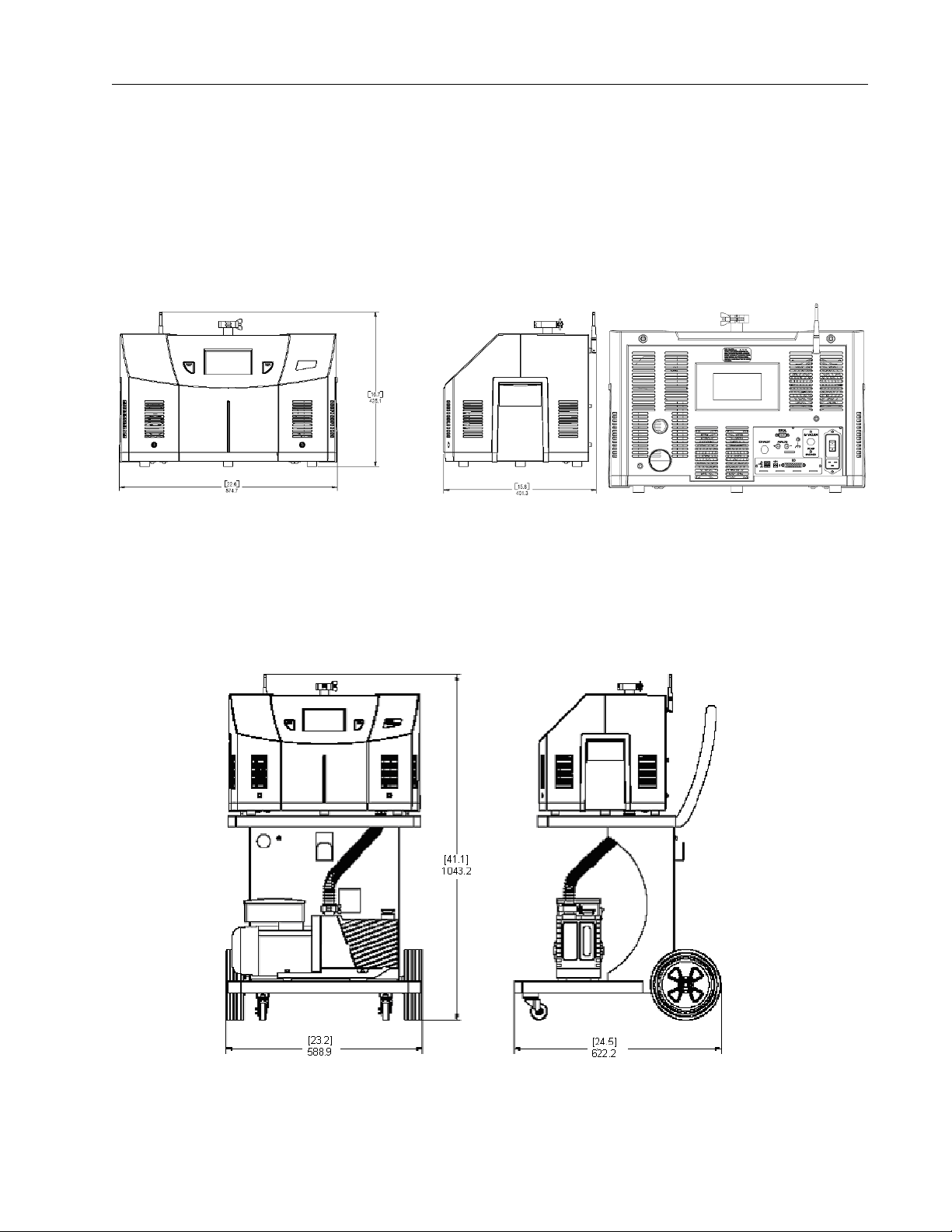
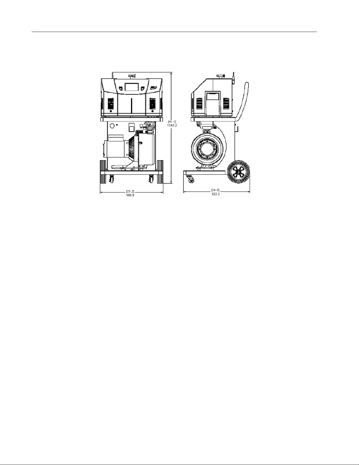
Figure 1-1 shows the outline drawing and physical dimensions of the portable leak detector
with Internal DS42 Wet Rotary Vane Pump, Model VS PR02 and the PD03, which utilizes a
Agilent IDP-3 dry pump.
Figure 1-1 Portable Leak Detector with Internal DS42 Wet Rotary Vane Pump, Model VS
PR02, and Portable Leak Detector with Internal IDP-3 (PD03) Dimensions
Figure 1-2 shows the outline drawing and physical dimensions of a mobile leak detector
with External DS302 Wet Rotary Vane Pump on a Cart, Model VS MR15.
D R A F T 9 / 2 5 / 1 2
Figure 1-2 Mobile Leak Detector with External DS302 Wet Rotary Vane Pump on a Cart,
Model VS MR15, Dimensions
1-3
Page 26
VS Series Helium Mass Spectrometer Leak Detectors
Figure 1-3 shows the outline drawing and physical dimensions of a Mobile Leak Detector
with External TS620 Dry Scroll Pump on a Cart, Model VS MD30.
Figure 1-3 Mobile Leak Detector with External TS620 Dry Scroll Pump on a Cart, Model VS
MD30, Dimensions
D R A F T 9 / 2 5 / 1 2
1-4
Page 27

VS Series Helium Mass Spectrometer Leak Detectors
1.2 Unpacking the Leak Detector
The following items are included in the shipment:
❑
VS Series Helium Mass Spectrometer Leak Detectors Operations Manual
❑
VS Series leak detector configured and completely assembled as ordered
❑
All necessary power cords, as ordered
❑
Pump manuals (for the purchased configuration)
❑
Any optional equipment ordered
❑
Any manuals for optional equipment purchased
1.2.1 Unpacking Instructions
To unpack the leak detector and remove it from the skid:
1. Inspect the container for evidence of damage in shipment.
a. Do not discard evidence of rough handling.
b. Report the damage to the carrier and to Agilent Customer Service without delay. See
the back cover of this manual for a listing of our sales and service offices.
2. Wear safety glasses and carefully cut the outer container holding straps.
3. Carefully remove the outer shipping container.
4. Inspect the leak detector and related items immediately for any indication of shipping
damage.
5. Carefully cut the leak detector holding straps.
6. Remove any loose boxes or packages and put them aside.
Keep the original packing for re-use in the event that it is necessary to return the leak
detector to Agilent.
7. Carefully remove the plastic bag covering the leak detector.
Proceed to Section 1.2.2 “Removing the Leak Detector from the Skid”.
D R A F T 9 / 2 5 / 1 2
1-5
Page 28

VS Series Helium Mass Spectrometer Leak Detectors
1.2.2 Removing the Leak Detector from the Skid
There are three methods for removing the leak detector from the skid, depending on the
leak detector model ordered. All methods require two people. The third method
involves removing the Skid-Mates (the blue donut-shaped mounts at the front of the
skid) from the skid.
WARNING
For portable and bench mount leak detectors (PD, PR, BR and BD models):
Method 1
1. With the assistance of a helper (one person per side), carefully lift the leak detector off
the skid using the leak detector side handles.
CAUTION
2. Gently place the leak detector on a designated flat surface.
3. Remove all loose packing from around the leak detector.
For mobile leak detectors (PD, PR, MR and MD models):
Handle the leak detector carefully and properly in the following
steps. Personal injury or damage to the leak detector could
result from improper handling. The leak detector is heavy and
can cause personal injury if not handled carefully when
removing it from the skid.
Keep the leak detector relatively horizontal when lifting. Lifting
the leak detector at a severe angle could cause oil to spill in
units with oil-sealed mechanical pumps installed.
D R A F T 9 / 2 5 / 1 2
Method 2
1. With the assistance of a helper, carefully roll the leak detector toward the front of
the skid.
2. Lift the front end of the unit and gently lower it onto the floor.
3. Lift the rear of the unit and roll it on the front casters until it is clear of the skid.
4. Gently lower the rear end onto the floor.
5. Take out and remove all loose packing from the leak detector.
1-6
Page 29

VS Series Helium Mass Spectrometer Leak Detectors
Method 3
1. Using a lever, carefully raise the front edge of the skid between 1" and 2".
2. While a helper holds the leak detector against the back brace, unscrew and remove the
front two Skid-Mates by turning them in a counterclockwise direction.
3. Make sure the helper is still holding the leak detector against the back of the skid, then
gently lower the front of the skid to the floor.
4. Carefully and slowly roll the leak detector off the skid and onto the floor.
5. Take out and remove all loose packing from the leak detector.
1-7
D R A F T 9 / 2 5 / 1 2
Page 30

VS Series Helium Mass Spectrometer Leak Detectors
Additional ventilation requirements for
your specific application are discussed in
Section 1.3.2 “Recommended Additional
Services” on page 1-11.
When installing a bench system with a
mechanical pump, the power cord for that
pump, if connected to the back of the leak
detector, cannot exceed three meters.
Additionally, connect the mechanical pump
to the leak detector using the shortest
possible vacuum connection to maximize
vacuum performance.
1.3 Installation
CAUTION
The VS Series Leak Detector is delivered completely assembled as ordered. Installation
requirements are described in Table 1-2.
Item Requirement
Leak Detector Location
Read the Preface for all operational warnings and cautions.
Table 1-2 Installation Requirements
❑
Close to its power source.
❑
Four inch clearance for proper ventilation.
❑
Sufficient room for the operator to safely maneuver to
perform testing.
D R A F T 9 / 2 5 / 1 2
Power Either (depends on configuration ordered):
❑
100 VAC, 50 Hz, 20 A
❑
115 VAC, 60 Hz, 20 A or
❑
230 VAC, 50/60 Hz, 12 A (models PR, MR and MD)
❑
230 VAC, 50 Hz, (model PD03)
1-8
Page 31

VS Series Helium Mass Spectrometer Leak Detectors
See the Mechanical Pump Operation
Manual that was enclosed with your pump.
Table 1-2 Installation Requirements (Continued)
Item Requirement
Mechanical Pump Oil Level Oil-sealed mechanical vacuum pumps are shipped with the
proper initial charge of oil. The oil level sight glass is on the front
of the pump.
❑
In the middle of the glass when the pump is not running.
❑
Check the oil level after running the pump for at least
10 minutes.
Mains Supply Voltage Fluctuations Must not exceed ±10% of the nominal voltage.
Pollution Pollution Degree 2 per EN61010-1 Standard.
Fixed Mains Socket Outlet Connect to a building protective earthing system.
D R A F T 9 / 2 5 / 1 2
1-9
Page 32

VS Series Helium Mass Spectrometer Leak Detectors
Note orientation of
valve
*
1.3.1 Bench System Installations
Figure 1-4 and Figure 1-6 represent the process for installation of the bench system version
of the VS Series Leak Detector.
Figure 1-4 is a drawing of a Bench Mount Leak Detector with External DS302 Wet Rotary
Vane Pump, Model VS BR15 with individual components shown.
Figure 1-4 Bench Mount Leak Detector with External DS302 Wet Rotary Vane Pump, Model
VS BRI5
Figure 1-5 is a drawing of a Bench Mount Leak Detector with External TS620 Dry Scroll
Pump, Model VS BD30 with individual components shown.*
NOTE
Cut the ¾” black tubing into two equal parts as shown.
D R A F T 9 / 2 5 / 1 2
Figure 1-5 Bench Mount Leak Detector with External TS620 Dry Scroll Pump, Model VS
BD30
1-10
Page 33

VS Series Helium Mass Spectrometer Leak Detectors
1.3.1 Helium
Welding grade helium in a standard cylinder with pressure regulating valve and hose is
required for testing products and leak checking.
1.3.2 Recommended Additional Services
The following additional services are recommended, based on the application:
❑
Connect an exhaust hose to the foreline pump and vent it outside of the room, or to
the facility’s exhaust, to reduce the particulate count and the helium background
signal.
❑
When using oil lubricated mechanical pumps, use an oil mist eliminator on the
exhaust port of the mechanical pump to reduce the oil mist from the exhaust.
Oil mist eliminators can, however, become saturated with oil causing slower
pumping speeds and higher helium backgrounds in the leak detector. The
replacement time interval of the oil mist eliminator is determined by whether the
user frequently operates at elevated roughing pressures, pumps on large volumes, or
frequently cycles the system. Refer to Table 4-4 on page 4-6 and Table 4-5 on
page 4-8 for the mist eliminator and replacement cartridge part number.
1.3.3 Storage
If the VS Series leak detector is not used immediately, it can be stored as received without
special precautions. A dry, relatively dust-free area is preferred. The required environmental
conditions for storage are:
❑
Dry nitrogen vent to keep the test port dry. Refer to Section 4.2 on page 4-5 for more
information.
❑
Adequate circulation to prevent an increased helium background level.
❑
0% to 95% relative humidity, non-condensing
❑
-20 °C (-4 °F) to + 60 °C (+ 140 °F) ambient temperature
CAUTION
Never leave any type of cell in the Wireless Remote unit if it is
will not be in use for a long period of time.
D R A F T 9 / 2 5 / 1 2
1-11
Page 34

VS Series Helium Mass Spectrometer Leak Detectors
Display
TEST (Hard)
Test Port
VENT (Hard)
Button
Button
Handle
(Recessed)
Model Label
1.4 Front Panel Display and Controls
The front panel (Figure 1-6) consists of two hard buttons: TEST and VENT and an LCD
display to access the software control screens. All operator control and monitoring of results
are achieved via the resident software accessed using the Home screen. Table 1-3 on
page 1-16 lists the main sub-screens and their purpose. Operational discussions are in
Section 2 “Operating the Leak Detector” on page 2-1 and in Section 3 “Set-Up”.
D R A F T 9 / 2 5 / 1 2
1-12
Figure 1-6 Front Panel Displays and Controls
The front panel display touch panel is calibrated at the factory and should not require
recalibration. If the touch panel buttons do not respond to pushes, recalibrate as follows:
1. Turn off the leak detector power.
2. Press and hold the center of the touch panel and restart power.
A blue screen appears.
3. Press the four cross hairs on the screen and accept the calibration.
Page 35

VS Series Helium Mass Spectrometer Leak Detectors
LCD Display Represents:
❑
Leak Rate - in a Bar Graph format with a numeric range
indicator
❑
Leak Rate, System Status and Parameters - in alphanumeric
format
❑
Series of
interface
Leak Rate, System Status and Parameters in alphanumeric format:
❑
Leak Rate is presented in a scientific notation: XXE-YY with
appropriate units
Where: X .X mantissa is a leak rate value
E- Y = 10-YY exponent is a leak rate range
X and Y are any numbers from 0 to 9
❑
System Status and/or Mode are represented on the screen in
alpha format on the screen and an italic font in this manual
❑
Parameters are represented on the screen in alphanumeric
format a bold font in this manual.
screens
with the soft key buttons for operator
Leak Rate Bar Graph The large bar graph displays the leak rate in one of three forms:
❑
A linear bar graph
❑
A logarithmic bar graph
❑
Both linear and logarithmic bar graphs
Use the Output Control Set-Up screen (Section 3.1.8.3.1 “Cal Leak
Expiration Set-Up” on page 3-23) to change the type of bar graph
that appears.
Over-range and under-range conditions are indicated using two up
and down arrows on the right and left side of the bar graph, respectively.
VENT The VENT button advances the leak detector to the vented state. A
red LED illuminates while the leak detector is in the vented state.
TEST When the system is in the Vent or Hold states, pressing the TEST
button automatically advances the leak detector through roughing,
then through the various test states, depending on the achievable
test port pressures and leak rates. A green TEST LED in the button
illuminates when the leak detector is in the Test or Fine Test state.
Press the VENT button to isolate the test port from the leak detector
vacuum system and vent the test port to atmosphere. The red VENT
LED remains lit while the leak detector is in the vented state. To
activate the VENT function, press and hold VENT for one second.
D R A F T 9 / 2 5 / 1 2
1-13
Page 36

VS Series Helium Mass Spectrometer Leak Detectors
HOLD With the leak detector in Test/Fine Test mode, press TEST again and
the leak detector goes into HOLD mode, isolating the leak detector
from the unit under test. The green LED in the Test button won’t
illuminate and the Home Screen displays Hold.
D R A F T 9 / 2 5 / 1 2
1-14
Page 37

VS Series Helium Mass Spectrometer Leak Detectors
MANUAL
TUNING
OUTPUT
CONTROL
SYSTEM
UNITS LANGUAGES
CONTROL PANEL
ACCESS
AUTO
SEQUENCER
SYSTEM
INFORMATION
TRANSFER
POINTS
LEAK RATE
RANGING
REJECT/AUDIO
SETPOINTS
CONTROL PANEL ZERO MENUS
MAIN SCREEN
CALIBRATION
SET-UP
SET-UP
MANUAL VALVE
CONTROL
ADVANCED
PARAMETERS
SET-UP
NEXT
MAINTENANCE
GAUGE
CALIBRATION
SET-UP
PASSWORD
P
ASSWORD
GROSS TEST
FORE
PUMP
DEFAULTS
EXHAUST PUMP
(PD03 O
NLY
)
WIRELESS
(O
PTION
)
The leak detector operator interface functions through a series of screens, which are
navigated as in Figure 1-7.
D R A F T 9 / 2 5 / 1 2
Figure 1-7 Screen Flow
1-15
Page 38

VS Series Helium Mass Spectrometer Leak Detectors
1.5 Display Panel Controls
Table 1-3 Screens – General Description
Screen Purpose
Home Accesses the Control Panel and Menu screens.
Activates the Zero function. The LED illuminates while zeroing occurs.
Accesses the Gross Leak Test screen, when Gross Test is initiated.
Control Panel Activates/deactivates:
❑
Std Leak
❑
Zero Enable
❑
Hold
❑
Calibrate
Displays the type of leak: Internal or external, associated with Calibrate.
Adjusts the speaker volume.
Menus Accesses the following screens for tailoring leak detector operation:
D R A F T 9 / 2 5 / 1 2
❑
Calibration Set-Up – Configures leak type, mode and parameters
(Section 2.2.4.1 on page 2-17).
❑
Reject & Audio Set Points – Configures parameters and toggles operations
on/off for each reject set point and for the audio threshold
(Section 2.2.4.2 on page 2-19).
❑
Leak Ranging – Configures the Range Stop, Manual Range values, toggles
the high pressure test feature and toggles operations on/off
(Section 2.2.4.4 on page 2-25).
❑
Transfer Pressure – Configures the Maximum Test Pressure
(Section 2.2.4.5 on page 2-28).
❑
System Information – Displays the status of configured and active items
(Section 2.2.4.6 on page 2-30).
❑
Control Panel Access – Activates/deactivates Vent and Panel Lockouts
(Section 2.2.4.7 on page 2-32).
❑
Auto Sequencer – Configures roughing and test times, toggles features
on/off and displays rough timer value (Section 2.2.4.3 on page 2-22).
❑
Set-Up - Accesses all the screens shown in Figure 1-7 on page 1-15.
1-16
Page 39

VS Series Helium Mass Spectrometer Leak Detectors
Table 1-3 Screens – General Description (Continued)
Screen Purpose
Set-Up Accesses the following screens:
❑
Advanced Parameters:
❑
Activates Autozero and Split Flow functions.
❑
Activates the Gross Leak function (Section 3.1.1 “Advanced Parame-
ters” on page 3-3).
❑
Sets Split Flow value (Section 3.1.1 on page 3-3).
❑
Output Control – Configures the Analog Output and
Bar Graph default units (Section 3.1.8.3.1 on page 3-23).
❑
Manual Tuning:
❑
Toggles between Filament 1 and 2.
❑
Sets Emission, Ion and Gain settings (Section 3.1.2 on page 3-7).
❑
Units – Configures Leak Rate and Pressure units
(Section 3.1.5 on page 3-15).
❑
Manual Valve Control – Access to control all valves (Section 3.1.3 on
page 3-10).
❑
Languages – Configures language (Section 3.1.6 on page 3-16).
❑
Gauge Calibration – Calibrates the Test Port Vacuum and Test Port ATM
reference points and displays Test Port Pressure and Spectrometer Pressure (Section 3.1.7 on page 3-17).
❑
Maintenance – Configures:
❑
Date and Time (Section 3.1.8.2 on page 3-21)
❑
Cal Leak Expiration and Internal Calibrated Leak values
(Section 3.1.8.3.1 on page 3-23)
❑
Password (Section 3.1.8 on page 3-19)
❑
Fore Pump and Diaphragm Pump (Section 3.1.10 on page 3-25).
❑
Wireless (Section 3.1.11 “Wireless” on page 3-27).
❑
System Defaults (Section 3.1.12 “System Defaults” on page 3-29).
D R A F T 9 / 2 5 / 1 2
1-17
Page 40

VS Series Helium Mass Spectrometer Leak Detectors
➀
➁
➁
➂
➃
➄
➅
7
9
10
11
➀
8
12
1.6 Rear Panel
The rear panel of the leak detector with an external mechanical pump (Model VS MR15 or
MD30) and a wireless remote control option is shown in Figure 1-8.
D R A F T 9 / 2 5 / 1 2
Figure 1-8 VS Series Rear Panel
➀
Serial Connector A 9-pin male D-type connector to interface with an external PC via
RS-232 type communications protocol for system diagnostic or
control.
➁
Cover Plate Access to expansion slot. This is not used when an optional I/O
➂
Power Entry
Module
A detailed summary of information related to serial communication
is provided in Section A “Communications Protocol” on page A-1.
PCB is installed. A rear panel of the optional I/O PCB is shown in
Figure 1-9 on page 1-19.
Provides supply power, overcurrent and EMI protection for the leak
detector. The Power Entry Module consists of:
❑
Power Input Connector - An IEC/EN60320/C20 standard,
three-prong grounded Inlet connector.
❑
Power Switch (I/O) - A 20A rocker type Power
Switch/Thermal Circuit Breaker.
❑
20 A EMC line filter.
1-18
Page 41

VS Series Helium Mass Spectrometer Leak Detectors
10
11
12
➃
➀ ➁
➂
➃
Fore Pump Power
Connection
➄
Analog Output Banana type output connector for an Isolated Leak Rate Analog
➅
Chassis (Earth)
Terminal
➆
Product Label A product label with part number, serial number and rating infor-
➇
RF Antenna A 2.4 GHz antenna for the optional Wireless Remote Control.
➈
Exhaust Cover Exhaust opening for a VS PR02 model.
Oil Level Cover Oil level window for a VS PR02 model.
An IEC/EN60320/C19 standard, three-prong grounded outlet
connector.
reading. The Red connector is a signal positive terminal; black is
the signal negative terminal. Signal range: From 0 to +10 VDC.
Later models of the VS will be equipped with a DB9F connector for
the analog output. Pin #1 is signal (positive) and Pin #2 is return
(negative).
Provided for additional connection of the leak detector to the
building grounding system to improve ESD protection.
mation.
Oil Drain Cover Oil drain opening for a VS PR02 model.
Nitrogen Vent Port Nitrogen vent port (On newer models).
Test Port Test port adapter (not shown).
2-Wheel Cart 2-wheel cart for an external fore pump (not shown)
Wireless Label A wireless info label for VS leak detector with an optional Wireless
Remote Control.
A rear panel for the optional I/O PCB assembly is shown in Figure 1-9.
Figure 1-9 Optional I/O PCB Rear Panel
D R A F T 9 / 2 5 / 1 2
➀
USB - A1 USB 1.1 full speed downstream port, USB type A receptacle.
➁
USB - A2 USB 1.1 full speed downstream port, USB type A receptacle.
➂
USB - B USB 1.1 full speed upstream port, USB type B receptacle.
1-19
Page 42

VS Series Helium Mass Spectrometer Leak Detectors
➃
I/O Connector A 25-pin female D-sub connector to interface with an external PLC
via a parallel cable.
Inputs:
❑
Four level inputs: optically isolated, (+5 to+24) VDC.
❑
Four momentary inputs: optically isolated, (+5 to+24) VDC,
requires 200 ms pulse width.
All inputs are opto-isolator LEDs with a series 3300 Ohm resistor.
Outputs:
❑
Eight optically isolated emitter followers with a 10 Ohm
series resistor, 14 mA max drive current, +24VDC max.
Power:
❑
An external power supply is supplied by the user.
A detailed summary of information related to I/O pin identifications
is provided in Table A-6 on page A-14.
D R A F T 9 / 2 5 / 1 2
1-20
Page 43

VS Series Helium Mass Spectrometer Leak Detectors
➁
➂
➃
➄
➅
7
9
➀
8
The rear panel of the leak detector (Model VS PR02 and PD03) is shown in Figure 1-10. The
optional Wireless remote control and I/O PCB is not installed.
Figure 1-10 Rear Panel (with Discrete I/O PCB)
Oil Drain For the internal mechanical vacuum pump (PR02 only, not shown).
Glass Window Oil level sight glass reading (PR02 only, not shown).
➀
Exhaust A barbed hose fitting (OD = 12.57 mm) for exhaust of the internal
mechanical vacuum pump.
➁
Serial Connector A 9-pin male D-type connector to interface with an external PC via
RS-232 type communications protocol for system diagnostic or
control
A detailed summary of information related to serial communication
is provided in Section A “Communications Protocol” on page A-1.
➂
USB Standard USB connector (types USB A and USB B).
➃
Power Entry
Module
Provides supply power, overcurrent and EMI protection for the leak
detector. The Power Entry Module consists of:
❑
Power Input Connector - An IEC/EN60320/C20 standard,
three-prong grounded inlet connector.
❑
Power Switch (I/O) - A 20A rocker type Power
Switch/Thermal Circuit Breaker.
❑
20 A EMC line filter.
D R A F T 9 / 2 5 / 1 2
➄
Vacuum Pump
Breaker
A 6 A Thermal Circuit Breaker for the internal mechanical pump.
1-21
Page 44

VS Series Helium Mass Spectrometer Leak Detectors
➅
Analog Output Banana type output connector for an Isolated Leak Rate Analog
reading. The Red connector is a signal positive terminal; black is
the signal negative terminal. Signal range: From 0 to +10 VDC.
Later models of the VS will be equipped with a DB9F connector for
the analog output. Pin #1 is signal (positive) and Pin #2 is return
(negative).
➆
Chassis (Earth)
Terminal
➇
25 Pin I/O
➈
Nitrogen Vent Port Nitrogen vent port (On newer models).
Provided for additional connection of the leak detector to the
building grounding system to improve ESD protection.
❑
Inputs: Opto-isolated, 5 - 24 VDC 3300 Ohm resistive load.
All inputs are opto-isolator LEDs with series resistors.
❑
Momentary Inputs: Opto-isolated, 5 - 24 VDC 3300 Ohm
resistive load, requires 200 ms minimum pulse width.
❑
Outputs: Emitter follower with 10 Ohm series resistor, 14
mA max drive current, 24 VDC max.
For pin identifications, see Table A-6 on page A-14.
1.7 Features
The features for the VS Series leak detector are provided in Table 1-4.
Table 1-4 VS Series Features
Feature Description
Calibration Fully automated tuning and calibration using the internal or external
calibrated leak. The fast calibrate feature allows calibration in less
D R A F T 9 / 2 5 / 1 2
Zero Control Selectable mode background elimination with a unique, patented
Leak Indication A bar graph (linear or log) indicator displays leak rates automatically;
than one minute.
Autozero<0 feature.
alphanumeric indication on LCD display. A leak can also trigger an
audible alarm frequency that varies in proportion to the size of the
leak, dedicated volume control and programmable audio threshold.
Analog voltage is proportional to the leak rate.
1-22
Page 45

VS Series Helium Mass Spectrometer Leak Detectors
Table 1-4 VS Series Features (Continued)
Feature Description
Pressure Indication Test port and spectrometer pressure with alphanumeric indication on
the LCD display.
Spectrometer Sensitivity optimized design, header mounted ion source with dual
thoria-coated iridium filament, a high sensitivity, wide dynamic range
preamplifier, and vacuum gauge.
Automatic Valve Sequencing Microprocessor-controlled valve operation provides automatic system
cycling.
Safety Interlocks A valve system design that completely protects the high vacuum
system under test against pressure surge and power interruption.
Optional
Wireless Remote Control This provides:
❑
RF communication between the VS leak detector (with base station or host) and the Wireless Remote unit from a distance up to
100 m (300 ft).
❑
The ability to enter the VS leak detector unit into Test and Hold
modes from the Wireless Remote unit's keypad.
❑
The ability to read the VS leak detector’s leak rate in a linear and
logarithmic bar graph format with a numeric range indicator and
System status in alphanumeric format on the Wireless Remote
unit's LCD display.
❑
Configuration up to 10 different VS leak detector unit’s for wireless
control by toggling through a MAC address list using one Wireless
Remote unit
Discrete I/O Control This provides 12 outputs and 8 inputs lines, optically isolated, to
control the VS leak detector using an external PLC via a 25-pin DB25
female connector and a user-provided parallel cable.
D R A F T 9 / 2 5 / 1 2
1-23
Page 46

VS Series Helium Mass Spectrometer Leak Detectors
D R A F T 9 / 2 5 / 1 2
This page intentionally left blank.
Page 47

VS Series Helium Mass Spectrometer Leak Detectors
Section 2. Operating the Leak Detector
2.1 Initial Startup, High Pressure Test Setup, and Shutdown
2.1.1 Startup
To start the leak detector:
1. Plug the leak detector power cord into an appropriate mains supply receptacle.
2. Move the power switch on the rear power control panel to the l position. If you have a
bench system with a separate backing/roughing pump, turn the pump on. The Vent and
Test buttons are disabled on start up until System Ready appears on the Home screen.
The System Ready indication appears on the Home screen. If the leak detector is being
started after a long period of being off (several hours), it can take up to three and a half
minutes to stabilize and provide reliable, quantitative leak rate readings.
The leak detector is capable of performing an automated calibration routine using either
an internal calibrated leak (factory installed), or an external calibrated leak placed into
the system test port. Refer to Section 2.2.4.1 “Calibration Set-Up” on page 2-17 to
properly set-up the leak detector for auto-calibration.
NOTES
3. Execute a calibration routine:
❑
Internal calibrated leak:
a. Press Test on the front panel to place the system in test mode.
b. Press Control Panel on the Home screen.
The Control Panel appears.
c. Press Calibrate.
If the system was recently calibrated before shut down, it can
be used for qualitative testing. Read the standard leak to verify
accuracy. For more accurate quantitative leak values, perform a
calibration 30 minutes after start-up.
To accurately read in the most sensitive decades (E-10 and
E-11), warm up the leak detector for at least one hour prior to
performing a full calibration. When leak checking in the E-9
atm-cc/sec range or higher, you can use the leak detector prior
to one hour and verify system performance by assuring that the
system can accurately read the internal calibrated leak.
The system is shipped from Agilent with the Range Stop
function turned ON and the bottom range set at the E-10 range
(atm-cc/sec). To accurately test in the E-11 range, careful
control of materials and the environment is required, consult a
Agilent sales engineer for support.
D R A F T 9 / 2 5 / 1 2
The system performs an automated calibration of the system.
2-1
Page 48

VS Series Helium Mass Spectrometer Leak Detectors
❑
External leak:
a. Press VENT to vent the leak detector and then install a calibrated leak into the
system test port.
b. Open the Calibration Set-Up screen and press External Leak (located under
Calibrate With).
c. Press Done.
d. Press Test to place the leak detector into Fine Test mode.
e. Press Control Panel on the Home screen.
The Control Panel appears.
f. Press Calibrate to perform an automated calibration.
For calibration in the E-10 range, the vacuum system must be sufficiently pumped to reduce
helium background below the E-10 range signal level. This is required to achieve an
acceptable signal-to-noise level and ensure accurate calibration.
E-10 range calibration is performed using an external calibrated leak. If an external
calibration is selected soon after system startup, the VS system evaluates the helium
background and determines if the background signal is sufficiently low to give an accurate
calibration. If the:
D R A F T 9 / 2 5 / 1 2
❑
System has pumped out sufficiently, the calibration proceeds.
❑
Background is changing, indicating the system is still pumping away background
helium, a countdown timer appears (Figure 2-1). The VS system monitors the helium
background and shows the time until the calibration begins. Should you prefer not
to wait, a Cancel button permits the calibration request to be cancelled.
NOTE
The firmware initially starts at a large time interval, but
recalculates the required time as the pumping continues. The
new time is reflected on the timer.
2-2
Figure 2-1 Helium Background Timer
Page 49

VS Series Helium Mass Spectrometer Leak Detectors
NOTE
When calibration is complete, the leak detector reverts to
Fine Test mode.
2.1.2 High Pressure Test Set-Up Procedure
The High Pressure Test mode locks the system into contraflow, offering maximum protection
to the spectrometer. This is useful in sniffing applications or when evacuating parts that can
contaminate the system.
To configure the High Pressure Test (optional):
1. Open the Leak Rate Ranging screen (Section 2.2.4.4 “Leak Rate Ranging” on page 2-25)
and turn the High Pressure Test feature ON.
2. If sniffing, vent the leak detector and attach a Agilent Power Probe
(Part Number K9565306) to the test port.
3. Monitor the test port pressure reading on the display and adjust the power probe flow
valve for a test port pressure of 0.5 to 1 Torr (2 Torr maximum). This pressure setting
allows for very rapid system response.
4. Press Zero on the Home screen to suppress the helium background signal.
High Pressure Test mode sensitivity is 10−4 to 10
between 1 and 2 Torr using the power probe.
When High Pressure Test is activated, range stop defaults to 10-7 atm cc/sec.
−8
atm cc/sec at test port pressures
2.1.2.1 Additional Sniffer Mode Setups
The following are highly recommended:
❑
In the Advanced Parameters menu (Section 3.1.1 “Advanced Parameters” on
page 3-3) set the Auto-Zero < 0 to Inactive.
❑
Block Probe Alarm:
❑
Activate the speaker and adjust the volume in the Control Panel screen.
❑
Go to the Section 2.2.4.2 “Reject and Audio Set Points” on page 2-19 and
activate the Audio Set Point. Program a pressure that is, ex. 20%, less than the
adjusted pressure of the power probe for sniffing.
If the pressure falls below the programmed Audio Set Point, a steady state alarm
tone is activated. This is extremely helpful in sniffing applications where the
probe could become blocked, thus missing potential leaks.
High Pressure Test mode sensitivity is 10-4 to 10-8 atm cc/sec at test port pressures
between 500mTorr and 2 Torr using the power probe. When High Pressure Test is
activated, range stop defaults to 10-7 atm cc/sec, but selecting between 10-4 to 10-8 atm
cc/sec is permitted.
D R A F T 9 / 2 5 / 1 2
2-3
Page 50

2.1.3 Shutdown
The system can be in any mode when shut down. When the system is shut down, all valves
in the system close. If the system is not in Vent mode, the test port remains under vacuum
and may be difficult to open.
To shut down the leak detector:
❑
VS Series Helium Mass Spectrometer Leak Detectors
Move the power switch on the rear panel to the°position.
D R A F T 9 / 2 5 / 1 2
2-4
Page 51

VS Series Helium Mass Spectrometer Leak Detectors
CALIBRATE
DONE
8.6E-07
EXTERNAL LEAK VALUE:
ATM-CC/SEC
5.0E-9
CLEAR
CANCEL
OK
1 2 3 4
5 6 7 8
* 9 0 -/+
OK
2.2 Screens
The leak detector display is used for the initial set-up and configuration of the leak detector.
Once the leak detector is set up and configured for a specific application, basic operation is
controlled primarily using the TEST and VENT buttons on the leak detector and the Home
screen Zero button (Section 2.2.2 “Home Screen” on page 2-7).
2.2.1 Basic Functions
Table 2-1 explains the basic on-screen functions used to enter or manipulate values.
Item Function
Table 2-1 Screen Basic Functional Items
Using the Calibrate button as an example, LEDs light when
the button is selected and activated.
Press Done to exit a screen.
Using a leak value as an example, press the value button and
a keypad appears for entering values.
Using External Leak Value as an example, these keypads
appear wherever values are entered. Enter the values with
the keypad and press OK.
The keypad values are dictated by the data required on the
parent screen. For example, if entering a leak rate value, the
system places an E or - sign in for the exponent.
Press:
❑
Clear to clear the display.
❑
Cancel to close the keypad screen without saving.
❑
OK to close the keypad and save.
Appears on screens more than one level from the Home
screen. Press this button to return directly to the Home
screen.
Used to increment/decrement values.
Saves all values on the screen and exits to the next higher
screen.
D R A F T 9 / 2 5 / 1 2
Moves you between menu selection screens when there is
more than one screen of choices.
2-5
Page 52

VS Series Helium Mass Spectrometer Leak Detectors
Table 2-2 explains the icons that appear on various screens and their meaning.
Table 2-2 On-Screen Icons
Icon Meaning
Indicates a feature is locked and cannot be activated due to a
higher level selection in the VS setup.
Indicates the status of the internal calibrated leak: If flashing, the
leak calibration will expire within 10 days. Steady and blue
indicates that the leak has expired. Steady and red indicates a
temperature sensor failure or a disconnected cable to the calibrated
leak temperature sensor.
Indicates a turbo pump fault.
Indicates that a valve is open.
D R A F T 9 / 2 5 / 1 2
Indicates the leak detector is in split flow.
Indicates there is a valve fault.
Indicates that a valve is closed.
Indicates that the split flow leak rate being entered is greater than
1000 times the indicated leak rate; the maximum permitted.
Indicates that the unit is in communication with a wireless remote
unit.
2-6
Page 53

VS Series Helium Mass Spectrometer Leak Detectors
0 1 2 3 4 5 6 7 8 9 10
-
10
7.8E-10 atm-cc/sec
T. P. PRESSURE:
FINE TEST
CONTROL
PANEL
ZERO MENUS
0.0E-04 TORR
-11 -10 -9 -8 -7 -6 -5 -4 -3
Log Bar Graph Display
Linear Leak Rate Display
The test port pressure
appears in black text
when pressure is too high.
when OK, and in red
The pump mode and
system status appear,
if applicable.
Accesses the
Menus screen
Accesses the
Control Panel
Zeroes out the helium signal
REJECT:
Reject
Setpoints
and status
and Range Exponent
Alphanumeric
leak rate
Units of
measurement
#3
#1
2.2.2 Home Screen
The Home screen displays a summary of the following status and configuration settings:
❑
Digital Leak Rate Display
❑
Leak Detector Status
(Table 2-3 on page 2-9)
❑
Reject Status Indicator
❑
Control Panel button
Two soft key buttons, Control Panel and Menus, give access for changing the leak detector
configuration (Figure 2-2).
❑
Test Port Pressure
❑
Condition Indication
(Table 2-4 on page 2-10)
❑
System Ready Indicator
(not shown)
❑
Menus button
❑
Gross Test button (not
shown)
Figure 2-2 Home Screen
Digital Leak Rate Correlates (Figure 2-2) directly with the log bar graph leak rate dis-
Test Port Pressure Appears on the Home screen and represents the test port pressure
play. The units for the measurements are selected on the Units
Set-Up screen (see Section 3.1.5 “Units” on page 3-15).
as measured by a thermocouple device mounted on the valve
block just below the test port. The pressure transducer and
associated electronics are intended to protect the leak detector
from damage due to over-pressure conditions. Use an external
pressure transducer if the test process requires a more accurate
monitoring of the test object pressure.
D R A F T 9 / 2 5 / 1 2
2-7
Page 54

VS Series Helium Mass Spectrometer Leak Detectors
Leak Detector Status Appears below the test port pressure reading and indicates the cur-
rent leak detector operating state. The normal operating states are
detailed in Table 2-3 on page 2-9.
Leak Detector
Condition
Reject Status Indicator Appears below the Leak Detector Condition on the left-hand center
Control Panel When pressed, opens the Control Panel screen (Section 2.2.3
Zero Zeroes out the helium leak indicated on the display. The Zero LED
NOTE
Appears below the Leak Detector Status and indicates the current
leak detector condition during abnormal conditions. See Table 2-4
on page 2-10 for a list of leak detector conditions.
of the Home screen when any of the four independent set points
are enabled and activated (Section 2.2.4.2 on page 2-19).
“Control Panel Screen” on page 2-12).
lights while zeroing is taking place. The leak rate must be less than
4.0E-7, while in Test, to allow a cross over to Fine Test.
The Zero button is only active while the leak detector is in the test
state and causes the leak detector to reset the leak rate display.
The leak detector automatically subtracts the recorded background
signal to display only the real leak rate.
Pressing Zero while introducing helium tracer gas to the test
object or while the helium background is varying significantly
could result in the suppression of a real leak. Only use the Zero
button after the helium tracer gas source has been removed.
D R A F T 9 / 2 5 / 1 2
The Zero capability allows the testing of sensitivity levels that are
below the system background. This feature also reduces test cycle
times by reducing the amount of time required for background
levels to naturally clean up or by allowing testing to begin at
relatively high test pressures. It is recommended that only two
decades of signal be zeroed out.
Menus Displays the Menus screen (Section 2.2.4 on page 2-16).
2-8
Page 55

VS Series Helium Mass Spectrometer Leak Detectors
T. P. PRESSURE:
GROSS TEST
CONTROL
PANEL
GROSS
MENUS
1.4E-02 TORR
Gross Test mode
indication.
Accesses the
Menus screen
Accesses the
Control Panel
TEST
Gross Test Displays Gross Test screen (Figure 2-3).
Figure 2-3 Gross Test Screen
Table 2-3 Leak Detector Operating States
Display Description
Calibrating Indicates that the leak detector is currently performing a calibration routine.
Test Indicates that the leak detector is in Test mode. When in Test mode, the Test
Port valve opens and the leak detector is ready for leak testing. Test leak rate
range is 1E-4 to 1E-8 (MDL 5E-9).
Fine Test Indicates that the leak detector is in Fine Test mode. When in Fine Test mode,
the test port valve opens and the leak detector is ready for fine leak testing.
Fine Test leak rate range is 9E-7 to 1E-11 (MDL 5E-12).
Hold Indicates that the leak detector is in Hold mode. When in Hold mode, all but
the foreline valves are closed, isolating the test port and any test objects or
fixturing from the leak detector vacuum system. Use Hold when you want to
keep the test port under vacuum without venting the test volume; this helps the
system clean up.
Roughing Indicates that the leak detector is currently performing a Roughing level
evacuation of the test port and any attached test objects or fixturing attached to
the test port.
D R A F T 9 / 2 5 / 1 2
Std Leak Indicates that the optional internal calibrated leak standard valve is open and
that the leak detector is reading the leak value.
Vented Indicates that the test port is vented to atmosphere. The test port and all objects
attached to the test port are isolated from the leak detector internal vacuum
system.
2-9
Page 56

VS Series Helium Mass Spectrometer Leak Detectors
Table 2-4 Leak Detector Condition States
Display Description
Backing Indicates that the leak detector is momentarily backing the foreline of the
high vacuum pump during an extended rough period. Backing occurs if the
roughing time is greater than 60 minutes or if the turbo pump is not ready.
Both Filaments
Burned Out/ No
Emission
Cal OK Indicates that the calibration routine was executed successfully.
Calibration Prep Indicates that the leak detector is preparing for a calibration routine.
Filament 1
Burnt Out
Filament 2
Burnt Out
Filament Wait Indicates that the system is lighting the filament.
Flashing C On
Exponent Display
Gain Too High Indicates that the gain value required to calibrate the leak detector during the
Indicates that no filament emission is detected. This can result from a PCB or
cable problem, or burned out filaments.
Indicates that filament 1 of the ion source has burnt out. Filament 2
automatically lights if it is still good, and a flashing C appears in the leak
rate exponent, indicating that a calibration routine is required.
Indicates that filament 2 of the ion source has burnt out. Filament 1
automatically lights if it is still good, and a flashing C appears in the leak
rate exponent, indicating that a calibration routine is required.
Indicates that the leak detector requires calibration.
calibration routine is greater than the maximum allowable value. This is
generally the result of system sensitivity being too low, due to normal system
aging.
D R A F T 9 / 2 5 / 1 2
Gain Too Low Indicates that the gain value required to calibrate the leak detector during the
calibration routine is less than the minimum allowable value. This is generally
the result of a system leak.
High Background Indicates a high Helium background detected during calibration self-test. This
typically, indicates a VS vacuum system leak.
No Ion Peak Indicates a tuning/calibration failure due to the system not detecting an ion
peak during the auto-tuning routine.
Offset Fault Indicates an electronics failure identified during calibration self-test.
Offset Wait Indicates that the system is setting the Offset value.
Reject Indicates a test object failure during an Auto Sequencer Test cycle.
See Section 2.2.4.3 “Auto Sequencer” on page 2-22.
Spec-Tube Flashes red when the spectrometer pressure > 1.0E-4 Torr.
2-10
Page 57

VS Series Helium Mass Spectrometer Leak Detectors
Table 2-4 Leak Detector Condition States (Continued)
Display Description
Stabilization Wait Indicates that the system is waiting for the electronics to stabilize before
completing the startup routine; up to two and a half minutes.
Std Leak Prep Indicates that the optional internal calibrated leak is being roughed before it is
introduced directly to the system for calibration verification.
Switching Filaments Indicates that the system is momentarily in the process of switching from a
burnt out filament to the next available filament.
System Pressure Wait Indicates that the system (spectrometer) pressure is too high to light the ion
source filament.
System Ready Indicates that the system is ready for testing. This message appears only during
the initial startup and is cleared after the first test cycle.
Zeroing Indicates that the leak detector is in the process of Zeroing out a background
signal. The Zero routine is initiated automatically during the startup and
calibration routines, or manually when the operator presses the Zero button on
the Home screen.
Zeroing Wait Indicates that the system is setting the initial zero values during the startup
routine.
D R A F T 9 / 2 5 / 1 2
2-11
Page 58

VS Series Helium Mass Spectrometer Leak Detectors
C
CONTROL PANEL
STD LEAK
✔
✕
EXTERNAL LEAK
ZERO ENABLE
✔
✕
DONE
+-
HOLD
CALIBRATE
0 1 2 3 4 5 6 7 8 9 10
Press the [+]
or [-] buttons to
adjust intensity.
Displays the
configured
leak type.
Toggles these
options on/off.
Engages/disengages
Hold
Runs the selected
calibration type
Toggles volume
on/off.
Press to
open the
Graphical
Display
2.2.3 Control Panel Screen
❑
Press Control Panel on the Home screen. The Control Panel screen appears
(Figure 2-4).
D R A F T 9 / 2 5 / 1 2
2-12
Figure 2-4 Control Panel
Std Leak Opens the standard leak valve so the leak can be seen by the
system.
The Std Leak button is only functional while the leak detector is in
fine test and activates the internal calibrated leak, allowing verification of the system calibration. When the system is in Std Leak
mode, Std Leak appears on the Home screen.
The Std Leak button isolates the test port from the system and
exposes the leak to the spectrometer. This allows you to compare
the displayed leak rate value to the calibrated leak value on the
System Information screen to verify proper system operation.
Because the test port is isolated from the fore pump in this mode,
a slight increase in test port pressure may be indicated on the test
port pressure display.
Zero Enable Turns on or off the zeroed out background. This feature excludes
the background leak from the leak rate signal.
Helium background represents helium that is in the system but
does not come from the part under test. If the background is zeroed
out, a more accurate measurement of the leak rate of the part is
determined. If Zero Enable is turned ON, the background is
excluded; if it is turned OFF, the system displays the full helium signal, including total background.
Page 59

VS Series Helium Mass Spectrometer Leak Detectors
Audio Volume Adjusts the volume up and down by pressing on the +/- buttons:
❑
When the leak rate bar graph display is set to Linear mode:
❑
The audio signal increases from a low to high frequency
as the leak rate increases within each decade.
❑
The pitch cycles low to high as it passes through each
decade. The audio response corresponds directly to the
size of the leak.
❑
To turn the sound on/off, press the speaker button. The
volume level is restored to the level it was at prior to being
turned off.
Hold Places the system in Hold; keeps the test port under vacuum and
does not vent. Use Hold to keep the system under vacuum, while
taking the leak detector out of test. This is useful if you want to let
the leak detector clean up the helium background, while keeping
the system under vacuum.
Press Hold while the leak detector is in the test state and the unit
advances to the Hold state. When in Hold mode, the test port is
isolated from the leak detector vacuum system. Since the test port
pressure gauge is located on the test port side of the isolation valve,
a subsequent rise in test pressure can be observed while in this
mode.
Calibrate Calibrates the system. Internal or External appears to indicate
which leak the system is using to calibrate.
Automated calibration is performed based on the parameters set on
the Calibration Set-Up screen (Section 2.2.4.1 “Calibration Set-Up”
on page 2-17). The Calibrate LED lights while calibration is taking
place.
The sequence of events is:
❑
The leak detector exposes the internal standard leak to the
system or verifies that the test port is roughed out and
exposes the external leak to the system.
❑
The ion voltage is scanned to find the peak signal.
❑
The system notes the leak rate reading, turns the leak off and
zeroes the system.
❑
A gain is calculated from the leak rate reading to make the
signal match the value of the calibrated leak and returns the
system to Test mode.
D R A F T 9 / 2 5 / 1 2
2-13
Page 60

VS Series Helium Mass Spectrometer Leak Detectors
NOTE
Figure 2-5 appears within the first twenty minutes of operation
if calibrate is selected. This message advises you that a twenty
minute warm up is strongly recommended after a cold start up.
This twenty minute warm up ensures optimum instrument
calibration and peak performance.
❑
Select No - No calibration is performed
❑
Select Yes - Calibration begins.
❑
No action - Keeps the message displayed and the leak
detector automatically calibrates after the 20 minute timer
times out. This could be slightly longer if the leak detector
has been off for a long period of time.
D R A F T 9 / 2 5 / 1 2
Figure 2-5 20 Minute Warm-up Dialog
2-14
Page 61

VS Series Helium Mass Spectrometer Leak Detectors
0 1 2 3 4 5 6 7 8 9 10
-
10
DONE
Linear Leak Rate Display
and Range Exponent
CLEAR DONEZERO
Zeroes out the helium signal
120
atm-cc/sec
sec
-03
-05
-07
-09
-11
1
720
Toggles the timing scale
2.2.3.1 Graphical Display Screen
The graphical display screen (Figure 2-6) represents the leak rate over time. The graphing
line appears in blue and changes to red when a reject set point is triggered.
Figure 2-6 Graphical Display
Timer Toggles the graphing time between 120 and 720 seconds. The
timer automatically defaults to 120 seconds on leak detector start
up. Press the toggle button while graphing to clear the current
graph. The data rate for the timers are:
120 seconds - two measurements/second
720 seconds - one measurement/three seconds.
Clear Clears the plotted graph. The graph automatically clears when the
leak detector is in roughing mode or at the start of a new test.
Zero Zeroes out the displayed helium leak. The leak rate must be less
than 4.0E-7, while in Test, to allow a cross over to Fine Test.
This button causes the leak detector to reset the leak rate display,
while the graph tracks the effect of the Zero command.
D R A F T 9 / 2 5 / 1 2
2-15
Page 62

VS Series Helium Mass Spectrometer Leak Detectors
0 1 2 3 4 5 6 7 8 9 10
C
CALIBRATION
SET-UP
LEAK RATE
RANGING
REJECT &
AUDIO
SET POINTS
TRANSFER
POINTS
CONTROL
PANEL
ACCESS
AUTO
SEQUENCER
SYSTEM
INFORMATION
SET-UP
Press a
button to
access specific
configurations.
2.2.4 Menus Screen
❑
Press Menus on the Home screen. The Menus screen appears (Figure 2-7). Use the
arrow to navigate to the previous screen.
The Menus screen consists of buttons to access the lower level screens used for
application-specific configuration.
NOTE
Pressing Zero while introducing helium tracer gas to the test
object, or while the helium background is varying significantly,
could result in the suppression of a real leak. Only use the Zero
button after the helium tracer gas source has been removed.
The Zero capability allows the testing of sensitivity levels that are
below the system background. This feature also reduces test cycle
times by reducing the amount of time required for background levels to naturally clean up or by allowing testing to begin at relatively
high test pressures. It is recommended to zero out only two
decades of signal.
D R A F T 9 / 2 5 / 1 2
2-16
Figure 2-7 Menus Screen
Page 63

VS Series Helium Mass Spectrometer Leak Detectors
-
10
CALIBRATION SET-UP
INTERNAL LEAK VALUE:
EXPIRES ON 08/02/2004
EXTERNAL LEAK VALUE:
CALIBRATE WITH
INTERNAL LEAK
EXTERNAL LEAK
MODE
FULL
FAST
DONE
1.5E-07 @ 26 °C
8.6E-07
0 1 2 3 4 5 6 7 8 9 10
Shows the
temperature
of the internal leak*.
Choose the
Calibration
Type.
Enter the
External Leak
Value.
Select leak used
for autocal.
compensated value
2.2.4.1 Calibration Set-Up
❑
Press Calibration Leak Set-Up on the Menus screen.
The Calibration Set-Up screen appears (Figure 2-8).
Use this screen to:
❑
View the value and expiration date of the Internal Calibrated Leak
❑
Enter the External Calibrated leak value
❑
Select whether to use an Internal or external calibrated leak
❑
Set the calibration mode: Full or Fast Calibration
The calibration routine can be executed without removing the test object or test
fixture from the test port.
Figure 2-8 Calibration Set-Up
Full Calibration Performs a thorough tuning process and a system gain adjustment
(calibration). The full tuning process involves scanning the ion
source chamber voltage, and optimizing each value for a maximum helium signal. Once the tuning process is complete, system
gain is adjusted to bring the leak detector into calibration. A full
calibration takes less than three minutes.
Fast Calibration Compares the leak rate signal with the calibrated leak value and
adjusts the gain to bring the system into calibration. If the gain
value is above the upper gain limit for the working range as defined
in Section 2.2.4.4 “Leak Rate Ranging” on page 2-25, then the fast
calibration process is terminated and a flashing c symbol appears
on the Home screen. A fast calibration takes less than 30 seconds.
* If the system cannot read the internal calibrated leak temperature, the system displays the
leak value and the temperature shown on the calibrated leak label. If this happens, the
calibrated leak symbol on the main screen turns red.
D R A F T 9 / 2 5 / 1 2
2-17
Page 64

VS Series Helium Mass Spectrometer Leak Detectors
Internal Leak Value The temperature-compensated internal leak value and expiration
date appear to the right of the Internal Leak Value text. The actual
Internal Leak Value and Expiration Date can be modified using the
Internal Calibration Leak screen (Section 3.1.8.3.1 “Cal Leak Expiration Set-Up” on page 3-23).
External Leak Value Displays the value on an operational button.
To configure an external leak:
1. Press External Leak (located under Calibrate With).
2. Press the button to the right of the External Leak Value text.
The data entry pad appears.
3. Enter the leak value and press OK.
For calibration in the E-10 range, the vacuum system must be sufficiently pumped to reduce
helium background below the E-10 range signal level. This is required to achieve an
acceptable signal-to-noise level and ensure accurate calibration.
D R A F T 9 / 2 5 / 1 2
E-10 range calibration is performed using an external calibrated leak. If an external
calibration is selected soon after system startup, the VS system evaluates the helium
background and determines if the background signal is sufficiently low to give an accurate
calibration. If the:
❑
System has pumped out sufficiently, the calibration proceeds.
❑
Background is changing, indicating the system is still pumping away background
helium, a countdown timer appears (Figure 2-9). The VS system monitors the helium
background and shows the time until the calibration begins. Should you prefer not
to wait, a Cancel button permits the calibration request to be cancelled.
NOTE
The firmware initially starts at a large time interval, but
recalculates the required time as the pumping continues. The
new time is reflected on the timer.
2-18
Figure 2-9 Helium Background Timer
Page 65

VS Series Helium Mass Spectrometer Leak Detectors
0 1 2 3 4 5 6 7 8 9 10
REJECT AND AUDIO SET POINTS
LEAK RATE #1
LEAK RATE #2
LEAK RATE #3
PRESSURE #4
AUDIO SET POINT
1.0E-08
2.0E-08
3.0E-08
5.0E+00
5.0E-08
✕
✕
✕
✕
✕
<
<
<
<
<
DONE
DONE
Toggles these
options on/off.
Press the desired
value to access
its keypad
Activates the reject
the programmed
set point if above
value
Activates the reject
the programmed
set point if below
value
2.2.4.2 Reject and Audio Set Points
Reject and Audio Set Points make the acceptance and rejection of parts more obvious. By
creating a set point, you let the system indicate if the part meets specification or not. For
example, you select LEAK RATE #1, set the value to 1.0E-8, set the reject activation to
greater than > (activate when the leak rate is above that set point), and turn the set point
ON. Then when the system is put into TEST, it indicates on the front panel that the part has
not meet the set point requirement, until it gets below the set point value and then the set
point failure indication disappears.
Multiple set points are used when you want to indicate several levels of acceptance. There
are times when you may want to assure the leak detector is working properly by bounding
the failure limit. For example, if LEAK RATE #1 were set as per above, then any leak rate
below 1.0E-8 would pass the part. Also assume that the leak detector was not seeing
helium, it would always pass parts. One way of preventing this from happening is to
periodically read the internal calibrated leak. Another way is to place a 5.0E-10 range leak
into the test port along with the part and program a second reject set point to fail if the leak
detector were to go below that value. In that case, you would program LEAK RATE #2 to
4.7E-10, set the reject activation to less than < (activate when the leak rate is below that set
point), and turn the set point ON. In this case, when the system is put into TEST, the system
indicates a failure if the leak rate goes below 5.0E-10.
❑
Press Reject & Audio Set Points on the Menus screen.
The Reject and Audio Set Points screen appears (Figure 2-10).
Use this screen to:
❑
Set the parameters to enable or disable.
❑
Display or change the value of the four reject set points and the audio set point.
Figure 2-10 Reject and Audio Setpoints
D R A F T 9 / 2 5 / 1 2
2-19
Page 66

VS Series Helium Mass Spectrometer Leak Detectors
Reject Set Points Active reject set points cause Reject to appear on the Home screen
along with the number of the reject set point that has been activated, which blinks to highlight the reject. The status of the reject
set points are also available through the RS-232 line (see
Appendix A “Communications Protocol”). Individual reject set
points can be disabled using the blue check/red X buttons located
to the right of each set point field.
There are four possible reject set points. Three reject set points can
be programmed to a leak rate value and one can be programmed to
test port pressure.
Set points may be turned ON or OFF (enabled or disabled) for each
set point. If a Reject Set Point is ON, then the rear panel output for
that set point goes active when its leak rate value is exceeded and a
reject indication appears on the Home screen.
Each reject set point is set to activate above or below the programmed value. To activate the reject set point:
❑
Above the programmed value, select the >.
D R A F T 9 / 2 5 / 1 2
❑
Audio Set Point Settings:
❑
NOTE
For Blocked Probe Alarm - High Pressure Test (Sniffing Mode)
see Section 2.1.2 “High Pressure Test Set-Up Procedure” on
page 2-3.
❑
Below the programmed value, select the <.
On:
The audio tone rate increases proportionally with each
decade that the measured leak increases above the set point
(leak rate pass/fail specification). The audio volume control
is located on the Control Panel (see Section 2.2.3 “Control
Panel Screen” on page 2-12).
Off:
The audio sounds for all leak rates above zero
(see Section 2.2.4.4 “Leak Rate Ranging” on page 2-25).
Set points may be turned ON or OFF (enabled or disabled).
When the Audio Set Point is OFF, audio sounds for all leak
rates above zero (see Section 2.2.4.4 “Leak Rate Ranging”
on page 2-25). When the audio set point is ON, audio
sounds only for leak rates above the audio set point.
2-20
To configure reject set points and the audio set point:
1. Press the blue check for the Reject Set Point.
2. Press the value button associated with the set point.
Page 67

VS Series Helium Mass Spectrometer Leak Detectors
The data entry pad appears.
3. Enter the set point and press OK.
4. Press the < or > soft key to select whether the reject setpoint activates above or below
the programmed value.
5. Press the blue check for the Audio Set Point.
6. Press the value button associated with the audio set point.
The data entry pad appears.
7. Enter the set point and press OK.
2-21
D R A F T 9 / 2 5 / 1 2
Page 68

VS Series Helium Mass Spectrometer Leak Detectors
2.2.4.3 Auto Sequencer
The auto sequencer is used to automatically perform testing on a part, to maximize testing
throughput and to reduce the chances of accidentally accepting a bad part. The auto
sequencer is used in conjunction with the reject and audio set point settings, which provide
the criteria for pass or fail conditions. Within the auto sequencer feature, there are two
variables that must be set, rough time and test time. The ROUGH TIME setting indicates to
the system the maximum time it is allowed to be in roughing before the test fails. Ideally, the
system goes into the roughing phase and then proceeds to TEST. The TEST TIME setting tells
the system when to perform the test against the set point values. For example, you may set
20 seconds for the TEST TIME. At the end of 20 seconds, the system determines if the part
has passed or not and then makes an indication by either going to VENT (Pass) or going to
HOLD (Fail) and displaying the reject set point failure on the front panel.
❑
Press Auto Sequencer Set-Up on the Menus screen.
The Auto Sequencer Set-Up screen appears (Figure 2-11). The leak detector can be
configured to automatically run through a complete test cycle
(Start/Rough/Test/Vent).
During the test cycle, the system ensures that during the Rough Time the
user-entered pressure transfer set points are met.
D R A F T 9 / 2 5 / 1 2
A Pass condition is indicated by the system reverting to the Vent mode upon
completion of the test cycle. A Fail condition is indicated by the system reverting to
the Hold mode, and all operating buttons being disabled except Vent. A failed
condition also results in Rejected appearing on the Home screen, along with a reject
set point activation upon completion of the test cycle. The status of the reject set
points are available through the RS-232 line (see Appendix A “Communications
Protocol”).
On completion of an automated test cycle, the leak detector captures the leak rate
signal measured just prior to the end of the automated test cycle. This leak rate
appears on the Home screen until the next test cycle is initiated.
2-22
Page 69

VS Series Helium Mass Spectrometer Leak Detectors
0 1 2 3 4 5 6 7 8 9 10
AUTO SEQUENCER
010
000
ROUGH TIME (SECS)
TEST TIME (SECS)
✔
✕
ROUGH TIMER
0 SECONDS
DONE
DONE
Press the desired
value to access
its keypad
Toggles these
options on/off.
Figure 2-11 Auto Sequencer
Rough Time Determines the amount of time that the leak detector is allowed
to evacuate the test object to the Maximum Test Pressure (see
Section 2.2.4.5 on page 2-28). In Auto Sequencer mode, the leak
detector transfers into test as soon as the specified transfer pressure
is met. If the specified test transfer pressure is not achieved within
the pre-selected rough time, the system aborts the cycle and goes
into Hold mode.
The Rough Time value is determined empirically and reflects the
typical time required to rough the test object to the specified test
pressure. Failure to achieve the test pressure within the pre-selected
rough time indicates a gross leak in the test object or test fixturing,
or that the time allowed was insufficient.
The rough timer records the amount of time the system spent in the
roughing phase prior to it entering the TEST mode. The rough timer
is intended to help you set up a rough time value since it can be
difficult to predict accurately how long the system is in the roughing phase when you cycle. Put the system into TEST mode, the
rough timer records and displays the rough time so that you can
enter a rough time value close to what was recorded. For example,
if the rough timer records a value of 12 seconds, you can then enter
a value in the rough time that is slightly longer than what was
recorded, 15 seconds for example. The rough timer only records a
time when the auto sequencer is ON.
D R A F T 9 / 2 5 / 1 2
2-23
Page 70

VS Series Helium Mass Spectrometer Leak Detectors
Test Time Determines the amount of time that the leak detector remains in
test before it compares the measured leak rate with the selected
reject set point. Allow sufficient time for the leak rate reading to
stabilize before the system makes a pass/fail decision. This is a
function of the part configuration and the leak rate specification. In
Auto Sequencer mode, the leak detector remains in test for the
entire duration of the preselected test time.
To configure the auto sequencer mode:
1. Press the blue check to turn on the Auto Sequencer.
The pass/fail criterion is based on the reject set points that are enabled.
2. Press the value button associated with the Rough time.
The data entry pad appears.
3. Enter the time and press OK.
4. Press the value button associated with the Test time.
The data entry pad appears.
D R A F T 9 / 2 5 / 1 2
5. Enter the time and press OK.
6. Press TEST and let the system record the actual time spent in roughing. After the test is
complete, use the recorded rough timer value to set an appropriate rough time.
2-24
Page 71

VS Series Helium Mass Spectrometer Leak Detectors
0 1 2 3 4 5 6 7 8 9 10
LEAK RATE RANGING
RANGE STOP
✔
✕
MANUAL RANGE
✔
✕
10-
09
10-
10
HIGH PRESSURE TEST
✔
✕
DONE
DONE
Press the desired
value to access
its keypad
Toggles these
options on/off.
Toggles these
options on/off.
2.2.4.4 Leak Rate Ranging
❑
Press Leak Rate Ranging on the Menus screen.
The Leak Rate Ranging screen appears (Figure 2-12). Use it to setup and enable the
Range Stop and Manual Range functions and to enable the High Pressure Test mode.
Figure 2-12 Leak Rate Ranging
High Pressure Test Press the High Pressure Test blue check to enable High Pressure
Test mode. The High Pressure Test LED illuminates when High
Pressure Test mode is enabled and High Pressure Test appears on
the Home screen. When High Pressure Test is selected, Range Stop
defaults to 10-7 atm cc/sec. High Pressure Test sensitivity mode
range is 10-4 to 10
❑
When the leak detector is in Vent mode:
-8
atm cc/sec.
Turn the High Pressure Test feature on to start the test cycle.
This automatically locks the leak detector into
Contra-Flow™ Leak mode, and auto-ranges through all
decades down to the most sensitive Contra-Flow range.
❑
When the leak detector is in Test mode:
Turn the High Pressure Test feature on to perform the same
function, with the exception of performing the test cycle
start sequence.
D R A F T 9 / 2 5 / 1 2
2-25
Page 72

VS Series Helium Mass Spectrometer Leak Detectors
Range Stop Configures the leak detector so that it only auto-ranges down to
the pre-selected decade entered in the Range Stop variable field.
For example, if range stop was enabled and the range stop setting
was 10
displays is full scale 10−7atm cc/sec. To allow auto-ranging to the
maximum sensitivity of the system, turn Range Stop Off.
This feature is useful when a product specification is more
than one decade less stringent than the actual sensitivity of the
leak detector. If the leak detector is capable of displaying full
scale < 10
the 10−7atm cc/sec range, then setting the range stop to
10
the need for the leak detector to reach its most sensitive scale
during each test cycle.
−07
, the most sensitive range that the leak detector would
−11
atm cc/sec, but the test specification is only in
−08
atm cc/sec would reduce the test cycle time by eliminating
D R A F T 9 / 2 5 / 1 2
NOTE
Activating the range stop extends the sensitivity requirements
for calibration, thus eliminating unnecessary calibration errors
(see Table 2-5).
Table 2-5 Range Stop/Sensitivity Requirements
Range Stop Max Gain MDL
OFF 6.9 5.00E-12
ON at
-11 6.9 5.00E-12
-10 10 5.00E-11
-9 20 5.00E-10
-8 50 5.00E-09
Manual Range Configures the leak detector so that it only displays the pre-selected
decade entered in the manual range variable field. For example,
if the manual range feature was enabled and the manual range
variable was set to 10
the LED bar graph during testing would be the 10
−06,
then the leak rate decade displayed on
−06
atm cc/sec
range only. This feature is useful when the concern is only with
monitoring the leak rate measurement within a single decade.
2-26
Page 73

VS Series Helium Mass Spectrometer Leak Detectors
To configure the leak rate ranging:
1. Press the Range Stop blue check button.
2. Press the associated Range Stop Value button.
The data entry pad appears.
3. Enter the value and press OK to save the value.
4. Press the Manual Range blue check button.
5. Press the value button associated with the Test time.
The data entry pad appears.
6. Enter the value and press OK to save the value.
7. Press the High Pressure Test blue check button, if required.
2-27
D R A F T 9 / 2 5 / 1 2
Page 74

VS Series Helium Mass Spectrometer Leak Detectors
0 1 2 3 4 5 6 7 8 9 10
-
00
TRANSFER POINTS
MAXIMUM TEST PRESSURE:
1.0E-00
DONE
Press the
value to access
its keypad
2.2.4.5 Transfer Points
❑
Press Transfer Points on the Menus screen.
The Transfer Points screen appears (Figure 2-13). Use it to set the pressure at which
the system goes into Test.
The transfer pressure settings can be adjusted to lower values for specific
applications. The limit on the maximum test pressure prevents the operator from
inadvertently setting the leak detector to transfer into test at too high a pressure,
which would result in excessive spectrometer contamination or ion source filament
failure.
D R A F T 9 / 2 5 / 1 2
Figure 2-13 Transfer Points
Maximum Test
Pressure
NOTE
Determines the test pressure cross over point at which the system
transfers from Roughing into Test and then into the Contra-Flow
Test mode. In the Contra-Flow Test mode, the gas sample is
pumped through the leak detector and swept across the high vacuum pump foreline. The Contra-Flow mode allows for higher sensitivity testing at exceptionally high test pressures.
The maximum test port pressure is 10 Torr.
The transfer pressure from the Test mode to the Fine Test mode
is set at 100 milliTorr (1.0E-1 Torr). You may wish to lower that
value under certain circumstances. The mid-stage transfer
pressure limit is adjustable from 1 to 100 milliTorr via an
RS-232 command (see?ML-XFER and INIT-ML-XFER in
Section A “Communications Protocol” on page A-1). The
pressure limit is not adjustable using the display.
2-28
Page 75

VS Series Helium Mass Spectrometer Leak Detectors
2.2.4.5.1 Transfer Points with Stabilization Wait Timer
Figure 2-14 shows the Transfer Points screen.
NOTE
Figure 2-14 Transfer Points with Stabilization Wait Timer
Stabilization Wait This appears on the Home screen after a successful startup. This
This feature is available November 2010.
timer is necessary for the spectrometer stabilization and degassing.
The factory default is 5 minutes. It is highly recommended for those
customers who infrequently use the leak detector or expose the
leak detector to aggressive applications to select the 9 or 15 minute
selection. For example: Select 9 minutes for a leak detector that is
used once a week or select fifteen minutes for a leak detector that is
used once a month or less.
D R A F T 9 / 2 5 / 1 2
2-29
Page 76

VS Series Helium Mass Spectrometer Leak Detectors
-
10
SYSTEM INFORMATION
FILAMENT 1 ✔ INTERNAL CAL LEAK
AUTO RANGING
CPU: LD01.00.02
LCD: DDO1.00.02
WWW.AGILENT.COM/
0 1 2 3 4 5 6 7 8 9 10
DONE
A blue check
denotes a good
filament; red is bad
.
GAIN: 1.5
Displays the Gain
2.2.4.6 System Information
❑
Press System Information on the Menus screen.
The System Information screen appears (Figure 2-15).
Details of the current leak detector setup and operating conditions are displayed.
The left column displays filament status, reject set point status, turbo status, auto
sequencer status, and audio set point status. The right column displays the
calibrated leak setting, leak rate range settings, and the sensitivity configuration.
Table 2-6 describes the displayed system information in detail.
a
D R A F T 9 / 2 5 / 1 2
Audio Set Point
See Section 2.2.4.2 “Reject and
Audio Set Points” on page 2-19.
Auto Sequencer
See Section 2.2.4.3 “Auto
Sequencer” on page 2-22.
Calibration Set-Up
See Section 2.2.4.1 “Calibration
Set-Up” on page 2-17.
Figure 2-15 System Information
Table 2-6 System Information Screen Conditions
Condition Display Description
Audio Set Point:
Audio Set Point is active.
Active
Audio Set Point:
Audio Set Point is inactive.
Inactive
Auto Sequencer: On Auto Sequencer (automatic test cycle)
is enabled.
Auto Sequencer: Off Auto Sequencer (automatic test cycle)
is disabled.
Int Cal Leak System is set to calibrate to the internal
Ext Cal Leak System is set up to calibrate to an
standard leak.
external standard leak.
2-30
Page 77

VS Series Helium Mass Spectrometer Leak Detectors
Table 2-6 System Information Screen Conditions (Continued)
Condition Display Description
Ion Source Filament
See Section 3.1.2 “Manual Tuning”
Filament 1 Off Filament 1 is selected and not lit.
Filament 1 On Filament 1 is selected and lit.
on page 3-7.
Filament 2 Off Filament 2 is selected and not lit.
Filament 2 On Filament 2 is selected and lit.
Gain Gain (Gain Value) Displays the gain that applied to the
leak rate. The actual helium signal is
multiplied by the gain value to read
the correct, calibrated leak rate.
Leak Rate Range
See Section 2.2.4.4 “Leak Rate
Ranging” on page 2-25.
Range Stop
See Section 2.2.4.4 “Leak Rate
Ranging” on page 2-25.
Auto Ranging System is set to auto range through
the leak rate scale.
Manual Ranging System is set for manual range control.
Range Stop -[Exp] System is set to display the most
[Exp]
sensitive leak rate range, 10
-
.
The range stop line shows only if
range stop is on.
Reject Set Point
See Section 2.2.4.2 “Reject and
Audio Set Points” on page 2-19.
Reject# 1,2,3,4 Active Reject set points displayed are active;
this line is blank when all set points
are disabled or inactive.
Software Version and
Agilent Web site
Split Flow
See Section 2.2.4.1 “Calibration
Set-Up” on page 2-17.
Vent Lockout Status
See Section 2.2.4.7 “Control Panel
Access” on page 2-32.
Shows the software version of the CPU
board (L version) and software version
of the display board (D version). Also
shows the Agilent web address for
customer use.
See the back cover of this manual for a
listing of our sales and service offices.
Shows split flow, only if the feature is
turned on. To change the status, go to
the Advanced Parameters screen.
Shows the status of the vent lockout
feature only if it is on. To change the
status of the vent lockout feature, go
to the Control Panel access screen.
D R A F T 9 / 2 5 / 1 2
2-31
Page 78

VS Series Helium Mass Spectrometer Leak Detectors
0 1 2 3 4 5 6 7 8 9 10
-
10
CONTROL PANEL ACCESS
✔
✕
PANEL LOCKOUT
✔
✕
DONE
VENT LOCKOUT
Toggles these
options on/off.
2.2.4.7 Control Panel Access
❑
Press Control Panel Access on the Menus screen.
The Control Panel Access screen appears (Figure 2-16). Use it to enable the Vent
and Panel lockouts.
D R A F T 9 / 2 5 / 1 2
Figure 2-16 Control Panel Access
Vent Lock Disables the VENT button. This option prevents accidental system
venting during test while under remote or PLC control. The Vent
Lock feature is not active when the Auto Sequencer is on.
Panel Lockout Disables the front panel buttons, TEST and VENT and access to the
Control Panel screen. This is primarily used while the system is
under PC or PLC control.
2-32
Page 79

VS Series Helium Mass Spectrometer Leak Detectors
0 1 2 3 4 5 6 7 8 9 10
C
ADVANCED
PARAMETERS
MANUAL
TUNING
UNITS
MANUAL
VALVE
CONTROL
OUTPUT
CONTROL
LANGUAGES
↸
↸↸
↸
Section 3. Set-Up
3.1 Set-Up Menu
The Set-Up menu screen contains buttons for functions that deal with machine
performance, tuning, and maintenance issues. All sub-screens below this level have a
Home button that returns the program directly to the Home screen (Figure 1-7 on
page 1-15).
❑
Press Set-Up on the Menu screen to open the Set-Up screen. The Set-Up menu can
be password protected. See Section 3.1.9 “Password” on page 3-24.
❑
Press the right arrow and then Maintenance on the Set-Up screen to access the
password change mechanism and enable or disable the password feature.
The password can also be read off the RS-232 connector (see Appendix A
“Communications Protocol”).
CAUTION
The items configured using the Set-Up sub-screens significantly
affect the performance of the leak detector and must only be
accessed by trained service personnel.
Many of the values for the parameters included on the Set-Up
sub-screens are calculated when the leak detector performs
functions such as Calibrate and tuning. Changing these values
can cause unreliable test results.
D R A F T 9 / 2 5 / 1 2
Figure 3-1 Set-Up Screen - Initial
3-1
Page 80

VS Series Helium Mass Spectrometer Leak Detectors
0 1 2 3 4 5 6 7 8 9 10
C
GAUGE
CALIBRATION
MAINTENANCE
↸
↸↸
↸
FORE
PUMP
SYSTEM
DEFAULTS
EXHAUST
PUMP
PASSWORD
Figure 3-2 Set-Up Screen - Second
See the following sections for these screens (all accessed from the Set-Up screen):
D R A F T 9 / 2 5 / 1 2
❑
Section 3.1.1 “Advanced Parameters” on page 3-3
❑
Section 3.1.2 “Manual Tuning” on page 3-7
❑
Section 3.1.3 “Manual Valve Control” on page 3-10
❑
Section 3.1.4 “Output Control” on page 3-13
❑
Section 3.1.5 “Units” on page 3-15
❑
Section 3.1.6 “Languages” on page 3-16
❑
Section 3.1.7 “Gauge Calibration” on page 3-17
❑
Section 3.1.8 “Maintenance” on page 3-19
❑
Section 3.1.8.3 “Internal Calibrated Leak” on page 3-22
❑
Section 3.1.8.2 “Date & Time Set-Up” on page 3-21
❑
Section 3.1.8.3.1 “Cal Leak Expiration Set-Up” on page 3-23
❑
Section 3.1.9 “Password” on page 3-24 (Software revision 3.11)
❑
Section 3.1.10 “Fore Pump Set-Up and Exhaust Pump” on page 3-25
❑
Section 3.1.10.1 “Date Serviced” on page 3-26
❑
Section 3.1.11 “Wireless” on page 3-27
3-2
Page 81

VS Series Helium Mass Spectrometer Leak Detectors
ADVANCED PARAMETERS
SPLIT FLOW
✔
AUTO-ZERO<0
ACTIVE
INACTIVE
1.5E-07
0 1 2 3 4 5 6 7 8 9 10
✕
LEAK RATE
DONE
DONE
Arrows to the left of
the bar graph indicate
the minimum
of the bar graph
indicate a leak rate
over the maximum
displayable value.
Toggles these
options on/off.
Accesses the
keypad to set
the Split Flow
Factor.
Activates the
Auto-zero function.
a leak rate under
displayable value.
Arrows to the right
▲ ▲
▲
▲
GROSS
TEST
3.1.1 Advanced Parameters
❑
Press Advanced Parameters on the Set-Up screen and the Advanced Parameters
screen appears (Figure 3-3).
Use this screen to configure the Auto-Zero < 0, Split Flow Factor, and spectrometer
Gain.
Figure 3-3 Advanced Parameters
Auto-Zero<0 Active Adjusts the zero reference point automatically and continually to
the correct zero value when the helium background level drops
below the previously set zero reference point. This feature ensures
that the leak detector maintains a correct balance value after a previously zeroed background signal naturally cleans up (background
helium is pumped away).
When the Auto-Zero < 0 feature is in the process of re-adjusting
the zero reference point, the arrows located on the left end of the
bar graph illuminate. These arrows indicate that the measured
helium leak rate is currently less than the minimum displayable
value. The arrows may flash briefly as the system recovers from a
leak indication and the displayable leak rate approaches zero. If
the Auto-Zero < 0 is turned on, the arrows may also flash briefly as
the system resets the zero point to a lower value. The leak detector
does not display a leak rate while the arrows are on. If the arrows
remain on for more than a few seconds, press Zero to set operating
parameters to the correct zero value. This situation can occur if the
leak detector had not been fully warmed up when a previous calibration was initiated.
D R A F T 9 / 2 5 / 1 2
3-3
Page 82

VS Series Helium Mass Spectrometer Leak Detectors
Auto-Zero < 0 Inactive When Auto-Zero < 0 is inactive, the leak detector does not
automatically adjust the zero reference point when the helium
background level drops below the previously set zero reference
point. In this condition, a leak less than the previously set zero
value is not indicated by the system. Instead, the arrows remain lit,
indicating that the background level is below the previously set
zero reference point. Press Zero on the front panel to readjust the
zero reference point manually. This clears the lights.
D R A F T 9 / 2 5 / 1 2
NOTE
For High Pressure Test/Sniffing mode, de-activation (Inactive
AZ<0) is highly recommended. Manual Zeroing produces a
more desirable performance, thus eliminating false leaks due to
fluctuations in test port pressure while in test.
Split Flow Activating the split flow option properly characterizes the system to
an external calibrated leak, which is influenced by additional vacuum pumping sources. These separate vacuum pumping sources
reduce the amount of helium measured by the leak detector.
The split flow option is very useful for external calibrations were
external gain factors exceed the limit of 50 due to a high helium
background (Range Stop E-8). The split flow factor is also useful for
calibrating to a standard leak while in the sniffing mode
(High Pressure Test).
Gross Test Allows the operator to locate leaks while the system is in roughing
mode. The test indicates the presence of a leak at high pressures
only and does not display a leak rate value.
❑
Gross Test is activated in the ADVANCED PARAMETER
menu.
❑
Once activated, the GROSS TEST button appears on the
Home screen. Press GROSS TEST to enter the screen.
3-4
❑
There is an audio tone for Gross Leak testing, which
increases as the leak increases.
❑
Gross Test only works when the test port pressure is between
10 and 150 Torr and remains constant (± 2% between
previous and current pressure readings).
❑
The Gross Leak test stops if the system goes into Backing,
Test or Fine TEST mode.
❑
Activating the Auto Sequencer button terminates the Gross
Leak test.
❑
The HOLD button is inactive while in Gross Leak test mode,
as the system is in roughing mode.
Page 83

VS Series Helium Mass Spectrometer Leak Detectors
3.1.1.1 Split Flow Operation
Ground rules and assumptions:
❑
The software limits split flow to no more than 1000 times (3 decades). If the split
flow is turned ON and the leak rate entered is more than 1000 times higher than the
system leak rate, the system will not allow the split flow to turn ON and <> appears.
❑
At the main screen, the system blinks the split flow symbol
ON.
❑
When split flow is turned ON, it displays the corrected leak rate but it knows the
real leak rate value.
❑
When ZERO is pressed with when split flow ON, the system zeroes out background
up to a limit equal to the maximum split flow value.
To activate split flow:
1. Place the system into TEST mode and let the leak rate stabilize. Calibrate the system.
2. Press the Split Flow blue check button. The leak detector prompts you to enter the leak
rate for the customer's calibrated standard leak (what the leak rate should be).
when split flow is
The leak detector displays the corrected leak rate, essentially calculating a split flow
gain value. The leak detector automatically calculates the split flow factor, turns on and
calculates the range stop, based on the split flow factor.
When Split Flow is turned OFF, the system reverts back to the uncorrected leak rate.
This process must be repeated when reactivating split flow.
For Split Flow: Sniffer Mode (High Pressure Test) External Calibration: (E-6, E-5, E-4 std.
leaks only) AZ<0 Inactive:
1. Install the power/sniffing probe in the leak detector test port and press Test. Transfer
Point must be equal to or greater than 2 Torr but less than 10 Torr.
2. Use the power probe to adjust the test port pressure between 500mTorr and 1 Torr for
optimum response and cleanup performance.
3. Initiate a full internal calibration.
4. Go back in Test and Zero out the system background.
5. Install the power probe in the outlet of the standard leak and allow for system
stabilization.
6. Activate the Split Flow option and input the value of the calibrated leak and press OK.
7. Remove the probe from the calibrated leak and verify that the that the leak detector
cleans up.
D R A F T 9 / 2 5 / 1 2
3-5
Page 84

VS Series Helium Mass Spectrometer Leak Detectors
8. Check to see if the leak rate signal is somewhat unstable and drifts lower than the
calibrated value. If so, lower the test port pressure with the power probe or utilize a
larger external calibrated leak.
Vacuum external calibrations were external gain factors exceed the limit of 50 due to a
high helium background (Range Stop E-8) can be performed as above, with the
exception that the background must be zeroed out prior to initializing split flow.
D R A F T 9 / 2 5 / 1 2
3-6
Page 85

VS Series Helium Mass Spectrometer Leak Detectors
MANUAL TUNING
0.963
258.6
EMISSION
ION
FILAMENT
1
0 1 2 3 4 5 6 7 8 9 10
GAIN:
DONE
OFFSET (µµµµV): 1126/9108
2.0
CANCEL
OK
CANCEL
OK
2
Increments/
the selected value
decrements
Select the
filament for use.
Select a value
to change it.
Accesses the
keypad to set Gain.
3.1.2 Manual Tuning
❑
Press Manual Tuning on the Set-Up screen and the Manual Spectrometer Tuning
screen appears (Figure 3-4).
Use this screen to manually adjust the parameters of the ion source in the
spectrometer for a maximum helium signal.
Figure 3-4 Manual Tuning
Emission Current Displays the value of the existing Emission current of the spectrom-
eter Ion Source and allows for emission current adjustment. The
emission current parameter tunes the leak detector, maximizing the
leak detector output for a peak helium signal.
Typical Emission current values range from 0.6 mA to 1.2 mA.
Ion Voltage Displays the current ion voltage value of the spectrometer Ion
Source. The ion voltage parameter tunes the leak detector, maximizing the leak detector output for a peak helium signal.
Typical ion voltage values range from 250 VDC to 270 VDC. The
ion voltage value is automatically adjusted and set during the full
calibration routine.
D R A F T 9 / 2 5 / 1 2
3-7
Page 86

VS Series Helium Mass Spectrometer Leak Detectors
Filament Switches between Filament 1 and 2. The filament selection can be
performed manually, but occurs automatically if the current operating filament burns out. A calibration routine is recommended every
time the operating filament is changed.
The change appears on the Home and System Information screens
and C flashes on the Home screen to indicate that calibration is
required.
D R A F T 9 / 2 5 / 1 2
NOTE
Gain Displays the current value of the Gain of the system. Gain is used
NOTE
To change a manual tuning parameter:
1. Press the desired parameter.
When you press the box containing the desired variable, a highlighted indicator appears
to the right of the numbers.
Replace the filament inside the spectrometer as soon as it is
convenient after the spare filament has been put into use.
to scale the indicated value of a known leak to agree with a known
correct value. The gain parameter is adjusted after the leak detector
has been tuned to helium. It is automatically set by the Calibrate
Procedure (see Section 2.2.4.1 “Calibration Set-Up” on page 2-17).
Use the value button (next to Gain) to change the Gain value.
Changing Gain changes Zero by the same percentage, which
can affect system transfer points.
Typical gain values range from 0.8 to 3.0. The higher the gain,
the more noise shows up in the least sensitive range.
3-8
NOTE
2. Press the Up or Down arrow to peak the helium signal.
NOTE
3. Press OK to accept the changes and to store the new parameter value in the leak
detector memory.
4. Press Done to exit the screen and return to the previous menu screen.
Once a change of value is initiated, you can press Cancel to
exit the screen and revert to the original value
Do not press the ESC box before pressing the OK box. This
causes the selected parameter to revert to its previously stored
value.
Page 87

VS Series Helium Mass Spectrometer Leak Detectors
To manually tune the leak detector:
1. Place the system in TEST mode.
2. Navigate to the Control Panel and turn the STD LEAK ON.
3. Navigate to the Calibration Set-Up screen and write down the INTERNAL CALIBRATED
LEAK value. This value is temperature compensated.
4. Navigate to the Manual Tuning screen and:
❑
Set the GAIN to 1.0.
❑
Set the EMISSION to between 0.600 and 0.6500.
❑
Adjust the ION value up or down to attain the maximum value. Ideally, the ION
value should be between 250 and 270.
❑
Adjust the EMISSION to attain the maximum value. Ideally, the EMISSION value
should be between 0.600 and 1.200.
❑
Set the GAIN so that the leak rate on the screen matches the value of the internal
leak you wrote down.
5. Navigate to the CONTROL PANEL and turn the STD LEAK OFF.
D R A F T 9 / 2 5 / 1 2
3-9
Page 88

VS Series Helium Mass Spectrometer Leak Detectors
Turbo bearing
temperature
Calibrated leak
temperature
3.1.3 Manual Valve Control
❑
Press Valve Control on the Set-Up screen and the Manual Valve Control screen
appears (Figure 3-5).
Use this screen to manually control the valves in the leak detector vacuum system
for troubleshooting purposes.
See Figure 3-7 on page 3-12 for an illustration of the leak detector vacuum system.
CAUTION
Manipulation of the valves using the Manual Valve Control
screen must only be performed by persons who are extremely
familiar with the leak detector as damage to critical
components (e.g., spectrometer, turbo) could occur.
D R A F T 9 / 2 5 / 1 2
3-10
Figure 3-5 Manual Valve Control
❑
Press the box corresponding to that valve to change the state of a specific valve.
The valve changes state and the box toggles from an X indication (CLOSED) to a
Green Circle (OPENED).
The valve state (displayed to the right of each valve control box) represents the
current state of the corresponding valve. The normal operating states of valves for
single mechanical pump systems are provided in Table 3-1 on page 3-12.
Page 89

VS Series Helium Mass Spectrometer Leak Detectors
Figure 3-6 shows this screen for the PD03; only the calibrated leak and bearing
temperature are accessible.
Figure 3-6 Manual Valve Control - PD03
D R A F T 9 / 2 5 / 1 2
3-11
Page 90

VS Series Helium Mass Spectrometer Leak Detectors
Test Port
Spectrometer
Test Port thermocouple
Calibrated Leak
V5
V4
V2 V3
V6
V7
V1
V1 Foreline
V2 Contraflow1
V3 Contraflow2
V4 Midstage1
V5 Midstage2
V6 Cal Leak
V7 Vent
*V8 Exhaust
*
V8
**
Table 3-1 Leak Detector Valve State Table - Single Mechanical Pump System
V4/V5
V2/V3
Leak Detector
Operating State
V1
Foreline
Valve
Contra-Flo
w Valve
Test Mode
Vent O C C C O C O
Rough C O C C C C C
Gross Leak Test C O C C C C N/A
Contra-Flow Test O O C C C C O
Midstage Test O C O C C C O
Hold O C C C C C O
Sniff O O C C C C O
Read Std Leak O C C O C C O
Midstage
Valve
Fine Test
Mode
V6
Calibrated
Leak
V7
Vent
Valve
V8*
Ballast
Valve
V8*
Exhaust
Valve
D R A F T 9 / 2 5 / 1 2
O: Open C: Closed
Figure 3-7 Leak Detector Vacuum System Diagram
* Normally open valve, powered closed during all operations. ** Model PD03 during the
3-12
roughing sequence.
Page 91

VS Series Helium Mass Spectrometer Leak Detectors
0 1 2 3 4 5 6 7 8 9 10
-
10
OUTPUT CONTROL
DONE
BAR GRAPH
LINEAR
LOG
LOG+LINEAR
ANALOG OUTPUT
LINEAR 10V/DEC
LOG 1V/DEC
Press to select the
Analog Output type.
Press to select the
bar graph units.
3.1.4 Output Control
❑
Press Output Control and the Output Control screen appears (Figure 3-8).
Use this screen to select the desired leak rate output, and Bar Graph display mode.
Figure 3-8 Output Control
Analog Output Configures the analog outputs:
❑
Linear 10 V/DEC
Linear output running from 0 to 10 V for each decade.
Figure 3-9 shows the linear output voltage as a function
of leak rate.
❑
Log 1 V/DEC
Log output at 1 V per decade. Figure 3-10 shows the log
output voltage as a function of pressure.
NOTE
For added accuracy add .06 to V
Leak Rate = 10
Vout+ .06
Bar Graph Configures the bar graph:
❑
Linear Only
The linear bar graph leak rate appears across the top of
all screens when selected. In the Linear Bar Graph display
mode, the bar graph display represents the mantissa of the
leak rate, spanning from 0 to 10. The numerical display
(located to the upper right of the bar graph) indicates the
leak rate exponent value. This mode offers exceptional
resolution within a decade.
/1011.
.
out
D R A F T 9 / 2 5 / 1 2
3-13
Page 92

VS Series Helium Mass Spectrometer Leak Detectors
Output Voltage = Leak Rate Mantissa
Output Voltage (Volts)*Standard and High Sensitivity Versions
Leak Rate (Std. cc/Sec)
Leak Rate Mantissa = Output Voltage
V = LOG (Leak Rate X 1011)
Output Voltage
Leak Rate atm-cc/Sec
Leak Rate = 10V/10
11
Figure 3-9 Leak Detector Linear Output Voltage
D R A F T 9 / 2 5 / 1 2
❑
Log Only
The log bar graph leak rate appears across the top of all
screens. In Log Bar Graph display mode, the bar graph
display represents the entire leak rate range of the leak
detector, spanning from 10
−11
atm cc/sec to 10−4 atm
cc/sec. The numerical display (located to the upper right of
the bar graph) is not lit in this mode.
Figure 3-10 Leak Detector Logarithmic Output Voltage
3-14
Log + Linear – both log and linear bar graphs appear across the top of the Home screen
while all other screens only display the linear bar graphs across the top.
Page 93

3.1.5 Units
0 1 2 3 4 5 6 7 8 9 10
-
00
UNITS
0 1 2 3 4 5 6 7 8 9 10
-
0
LEAK RATE
TORR-L/SEC
PA-M3/SEC
CUBIC-FT/YR
ATM-CC/SEC
MBAR-L/SEC
PA-M3/SEC
PRESSURE
TORR
MBAR
PA
DONE
Press to select the
leak rate type.
Press to select the
pressure units.
VS Series Helium Mass Spectrometer Leak Detectors
❑
Press Units on the Set-Up screen and the Units screen appears (Figure 3-11).
Use this screen to configure the Leak Rate and Pressure Units used on the leak rate
bar graph.
Figure 3-11 Units
Leak Rate Units Switches the leak rate units between atm-cc/sec, mbar-l/sec,
Torr-l/sec, Pa-m3/sec., and Cubic-ft/yr.
Pressure Units Switches the test port pressure units between Torr, mbar, and Pa.
D R A F T 9 / 2 5 / 1 2
3-15
Page 94

3.1.6 Languages
0 1 2 3 4 5 6 7 8 9 10
-
10
LANGUAGES
MANDARIN
PA-M3/SEC
ENGLISH
FRANÇAIS
KOREAN
KANJI
DEUTCH
ESPAÑOL
DONE
Press to select the
language in use.
❑
VS Series Helium Mass Spectrometer Leak Detectors
Press Language Set-Up on the Set-Up screen and the Languages screen appears
(Figure 3-12).
Use this screen to select a language.
D R A F T 9 / 2 5 / 1 2
Figure 3-12 Languages
3-16
Page 95

VS Series Helium Mass Spectrometer Leak Detectors
0 1 2 3 4 5 6 7 8 9 10
-
10
GAUGE CALIBRATION
TEST PORT VACUUM
TEST PORT ATM
TEST PORT PRESSURE:
SPECTROMETER PRESSURE:
<1.0E-03 TORR
. 1.0E-06 TORR
DONE
CAL FAILED
Changes during
the procedure.
Display only.
CAL OK
CAL FAILED
CAL OK indicates
valid calibrations.
indicates a failed
Press to activate the
calibration type.
cal.
3.1.7 Gauge Calibration
❑
Press Gauge Calibration on the Set-Up screen and the Gauge Calibration screen
appears (Figure 3-13).
Use this screen to perform a calibration on the test port thermocouple gauge.
Calibrate the thermocouple gauge for the most accurate operation. To calibrate the gauge:
1. Set a calibration point at atmosphere.
2. Set a calibration point at a low vacuum level (<= 1E-4 Torr).
Figure 3-13 Gauge Calibration
Test Port Vacuum Calibrates the thermocouple gauge zero value. Do this at or below
1E-4 Torr.
Test Port ATM Sets the thermocouple atmospheric value. Perform this operation
only when the test port is at atmosphere.
Test Port Pressure and
Spectrometer Pressure
Test Port Pressure
Gauge Calibration
Procedure
NOTE
The Test Port Pressure and the Spectrometer Pressure values appear
on this screen for reference.
Calibrates the test port pressure thermocouple gauge. Perform both
the Vacuum and Atmospheric Calibration procedures in the order
written, TEST PORT VACUUM and the TEST PORT ATM.
Display of <1.0E-03 indicates the pressure is less than the
lowest displayable pressure of the TC gauge which is 1.0E-03.
D R A F T 9 / 2 5 / 1 2
3-17
Page 96

VS Series Helium Mass Spectrometer Leak Detectors
3.1.7.2 Vacuum (Low Pressure) Calibration
To perform Vacuum Calibration:
1. Verify that the leak detector is in the System Ready condition and that a test port cap is
in place.
2. If the system is not already in Vent mode, press VENT.
3. Press Test and verify that the leak detector transfers to Fine Test mode,
displaying 10−9atm cc/sec or lower.
4. Wait approximately 5 minutes for the vacuum system pressure to stabilize.
5. Press Test Port Vacuum.
You will receive one of the following messages:
❑
A Cal OK indicator, to the right of the Test Port TC Zero box confirms that the
calibration was successful.
❑
A Failed message indicates that the calibration was not successful.
A Failed message results from a defective or contaminated thermocouple gauge, or
the fact that the actual pressure was not at or near zero. Verify the latter case using an
appropriate vacuum gauge installed on the test port.
6. Press Done to leave the screen and return to the previous menu.
3.1.7.3 Atmospheric Calibration
To perform Atmospheric Calibration:
1. If the system is not already in Vent mode, press VENT.
2. Wait approximately ten seconds for the test port pressure to stabilize, then move to the
D R A F T 9 / 2 5 / 1 2
Gauge Calibration screen (Figure 3-13 on page 3-17).
3. Press Test Port Atm.
You will receive one of the following messages:
❑
A Cal OK indication, to the right of the Test Port TC Atm box, confirms that the
calibration was successful.
❑
A Failed message indicates that the calibration was not successful. This is the result
of a defective or contaminated thermocouple gauge, or that the actual pressure was
not at or near atmosphere. Verify the latter case using an appropriate vacuum gauge
installed on the test port.
4. Press Done to leave the screen and return to the previous menu.
3-18
Page 97

3.1.8 Maintenance
0 1 2 3 4 5 6 7 8 9 10
-
10
MAINTENANCE
DATE & TIME
10/27/2005 04:16 PM
PASSWORD
✔
✕
CHANGE PASSWORD
INTERNAL
CALIBRATED LEAK
DONE
Toggles these
options on/off.
Accesses the
Current Date &
Time Set-Up
screen.
Accesses the
Internal Calibration
Leak screen.
Accesses the
Password keypad.
(Software revs
3.10 and earlier)
❑
Press Maintenance on the Set-Up screen and the Maintenance screen appears
(Figure 3-14).
Use this screen to configure:
❑
❑
❑
❑
VS Series Helium Mass Spectrometer Leak Detectors
The PASSWORD and to turn that feature ON or OFF (Software revisions 3.10
and earlier.
Section 3.1.8.1 “Turbo Vent” on page 3-20
Section 3.1.8.2 “Date & Time Set-Up” on page 3-21
Section 3.1.8.3 “Internal Calibrated Leak” on page 3-22
Figure 3-14 Maintenance
Password Activates/deactivates the password function. When activated,
pressing Maintenance from the Menus screen opens the password
prompt screen.
Change Password Changes the password used to access the Set-Up and Maintenance
screens. Enter up to six numeric values for the password and
confirm the password selection. An empty entry is not allowed. If
no password is entered, the old password is used. The default password from the factory is 777777. You will need this when changing
to a new password.
NOTE
The password can also be read through the RS-232 port in the
event of a lost password. See Table A-1 on page A-5 and
Table A-2 on page A-8.
D R A F T 9 / 2 5 / 1 2
3-19
Page 98

3.1.8.1 Turbo Vent
Selecting the Turbo Vent button prepares the unit for transportation by venting the system
and prompting the operator to power down the unit (Figure 3-15). Pressing the Turbo Vent
button:
VS Series Helium Mass Spectrometer Leak Detectors
D R A F T 9 / 2 5 / 1 2
Figure 3-15 Vent Turbo Dialog
1. Closes all the valves.
2. Opens the vent valve.
3. Opens the mid-stage valves.
4. Turns off power to the Ion Source board.
This sequence prevents a pressure burst to the spectrometer and turbo pump so the
turbo pump isn’t damaged during a move.
3-20
Page 99

VS Series Helium Mass Spectrometer Leak Detectors
0 1 2 3 4 5 6 7 8 9 10
-
10
CURRENT DATE & TIME SET-UP
YEAR
MONTH
DAY OF THE WEEK
2005
01
DAY
02
MONDAY
DONECANCEL
1M/PM/24
HOUR
PM
04
30
OK
MINUTE
3.1.8.2 Date & Time Set-Up
❑
Press the button next to Date & Time.
The Current Date & Time Set-Up screen appears (Figure 3-16).
Figure 3-16 Current Date & Time Set-Up
To configure the Date & Time screen:
1. Press a button to activate its field.
2. Use the Up and Down arrows or keypad to set the value.
3. Press Done for each item configured.
4. Repeat step 1 through 3 for each desired item.
5. Press OK to exit the screen.
D R A F T 9 / 2 5 / 1 2
3-21
Page 100

VS Series Helium Mass Spectrometer Leak Detectors
0 1 2 3 4 5 6 7 8 9 10
-
10
INTERNAL CALIBRATION LEAK
INTERNAL LEAK VALUE
CAL LEAK EXPIRATION
1.4E-07
24
08/02/2006
DONE
Accesses the
Internal Leak Value
keypad.
Sets the temp.
at which the leak
Accesses the
Cal Leak Expiration
Set-Up screen.
was calibrated.
TEMPERATURE °C
±
-3
3.1.8.3 Internal Calibrated Leak
❑
Press Internal Calibrated Leak.
The Internal Calibrated Leak screen appears (Figure 3-17).
D R A F T 9 / 2 5 / 1 2
3-22
Figure 3-17 Internal Calibrated Leak
To use this screen:
1. Press a button to activate its field.
A keypad appears.
2. Enter the required values as shown on the calibrated leak label.
3. Repeat step 1 and 2 for each desired item.
4. Press Done to exit the screen.
The value of the internal calibrated leak, as shown on the CALIBRATION SET-UP and
CONTROL PANEL screens, is compensated for temperature using the calibrated leak
temperature sensor. The calibrated leak is not compensated for temperature if any of the
following conditions exist:
❑
The temperature sensor on the calibrated leak fails or there is a cable connection
problem.
❑
The temperature sensor reading is out of the operating range. The operating
temperature range is from 10.0 to 45.0° C (50 to 113° F).
❑
The internal calibrated leak is not a E-7 or E-8 range leak.
 Loading...