

Page 1

Agilent M1165/66/67/75/76/77A
Component Monitoring System
and
Agilent M1205A V24 & V26
User’s Reference Manual
Volume 1
System Information
s1
Part Number M1046-900 1L
Printed 06/2000
First Edition
Page 2

Notice
This document contains proprietary information which is protected by copyright. All Rights
Reserved. Reproduction, adaptation, or translation without prior w rit ten permission is
prohibited, except as a llowed under the copyright laws.
Agilent Technologies
3000 Minuteman Road
Andover, MA 01810-1085
(978) 687-1501
Publication number
M1046-9001L
Warranty
The information contained in this document is subject to change without n otice.
Agilent Technologies ma kes no warranty of any kind with regard to this material, including,
but not limited to, the implied warranties or merchantability and fitness for a particular
purpose.
Agilent Technologies shall no t be liable for errors contained herein or for incidental or
consequential damages in connection with the furnishing, performance, or use of this
material.
Copyright © Agilent Technologies, 2000
ii
Page 3

Printing History
0366
0123
New editions of this document will incorporate all material updated since the previous edition.
Update packages may be issued bet ween editions and contain replac ement and additional
pages to be merged by a re vision date at the bottom of the pa ge. Note that pages which are
rearranged due to ch anges on a previous page are not considered revised.
The documentation printing date and part number indicate its current edition. The printing
date changes when a new edition is printed. (Minor corrections and updates which are
incorporated at reprint do not cause the date to change.) The document part number changes
when extensive technical ch anges are incorporated.
First Edition . . . . . . . . . . . . . . . . . . . . . . . . . . . . . . . . June 2000
Important
United States federal law restricts these devices to sale by or on the order of a physician.
The M1165/66/75/76A Systems comply with UL544, CSA 22.2-125, IEC 601-1, EN 60601-1, and
EN 60601-1-2 and car r ies Marking to Counci l Dir ec ti ve 93/ 4 2/ EEC, E ur opean Medical
Device Directive (MDD).
The M1167/77A Systems comply with UL2601-1, CSA 22.2 No. 601.1-M90, IEC 601-1,
EN 60601-1, and EN 60601-1-2 and carries Marking to Council Directive 93/42/EEC,
0366
European Medical Device Directive (MDD).
The M1205A Systems comply with UL2601, IEC 601-1, CSA C22.2 no. 601-1, EN60601-1, and
EN60601-1-2 and carries Marking to Council Directive 93/42/EEC, European Medical
Device Directive (MDD).
iii
Page 4

Electromagnetic Interference
Anomalies due to electromagnetic interference are not unique to the M1165/66/67/75/76/77A
or the M1205A but are chara cteristic of patient monitors in use today. This performance is
due to the very sensitive high gain front end amplifiers used to display the physiological
signals. Among the many similarly performing monitors already in use by customers,
interference from electromagnetic sources is rarely a problem in actual use.
Avoiding Electromagnetic Interference
When electromagnetic interference (EMI) is encountered there are a number of actions that
can be taken to mitigate the problem.
• Eliminate the source. Possible sources of EMI can be turned off or moved away to
reduce their strength.
• Attenuate the coupling. If the coupling path is through the patient leads, the
interference may be reduced by moving and/or rearranging the leads. If the coupling is
through the power cord, plugging the monitor into a dif ferent circuit may help.
• Reduce the sensitivity of th e syst em . In all o f th e EM C t esti n g the m oni to r wa s adju ste d
to maximum sensitivity. For the ECG amplifier the gain was four times what is
normally required. By reducing the gain of the system receiving the EMI, the
interference can often be eliminated.
• Add external attenuat ors. I f E MI becomes an unusually difficult problem external
devices such as an isolation transf ormer or a transient suppressor ma y be of help. An
Agilent Customer Engineer can be of help in determining the need for external devices.
iv
Page 5

Intended Use
Intended Use
Description
The Agilent M1165/66/67/75/76/77A Component Monitoring System and the Agilent M1205A
V24 and V26 Monitors are ne tw ork connectable bedside patient monitoring devices.
The Agilent M1205A Models V24CT and V26 CT may powered by either AC line power or by
battery power.
Purpose
The Agilent M1165/66/67/75/76/77A Component Monitoring System and the Agilent M1205A
V24 and V26 monitors measure and display multiple ph ysiological parameters and w aves, and
generate alarms and recordings. They exchange information with compatible devices. The
Agilent M1165/66/67 /75/76/77A Component Monitoring System and the Agile nt M1205A V24
and V26 monitors are not therapeutic devices.
Patient Population
The Agilent M1165/66/67/75/76/77A Component Monitoring System and the Agilent M1205A
V24 and V26 monitors are intended to be used on adult, pediatric, an d neonatal patients.
Environment
The Agilent M1165/66/67/75/76/77A Component Monitoring System and the Agilent M1205A
V24 and V26 monitors are intended to be used in a clinical environment by trained healthcare
professionals. They are not intended for home use.
They communicate with de vices such as a central station through network interface ports and
a serial I/O port.
The Agilent M1165/66/67/75/76/77A Component Monitoring System and the Agilent M1205A
V24 and V26 Monitors are pres cription devices and will carry the following label, “United
States Federal law restricts this device to sale by or on the order of a physic ian.”
v
Page 6

Indications for Use
Indications for Use
Condition
The Agilent M1165/66/6 7/75/76/77A Component Monitoring System and the Agilent M1205A
V24 and V26 Monitors are generally indicated when the clinician decides there is a need to
measure and display multiple physiological parameters and waves, to generate alarms and
recordings of adult, pediatric, or neonatal patie nts.
Part of Body or Type of Tissue with Which the Device Interacts
The Agilent M1165/66/6 7/75/76/77A Component Monitoring System and the Agilent M1205A
V24 and V26 monitors do no t c ontact the body or tissue of the patient. Signals are obtain ed
from accessory electrode, transducer, and sensor devices.
Frequency of Use
The Agilent M1165/66/6 7/75/76/77A Component Monitoring System and the Agilent M1205A
V24 and V26 monitors ar e indicated for use when presc ribed by a clinician.
Physiological Purpose
The Agilent M1165/66/6 7/75/76/77A Component Monitoring System and the Agilent M1205A
V24 and V26 Monitors are indicated when the purpose is to gain information for treatment, to
assess adequacy of treatment, or to rule out causes of symptoms. The Agilent M1165/66/67/
75/76/77A Compon e nt Mo n it or i n g Syste m an d the Agi le n t M120 5A V24 an d V26 mo n itors are
well suited for patient m onitoring.
Patient Population
Adult, pediatric, and neonatal non-ambulatory patients.
vi
Page 7

Indications for Use
Prescription Versus Over-the-Counter
The Agilent M1165/66/67/75/76/77A Component Monitoring System and the Agilent M1205A
V24 and V26 Monitors are prescription devices.
vii
Page 8

Indications for Use
Warnings, Cautions, and Notes
Warnings, cautions, and notes are us ed throughout this User’s Manual to give you additional
information about the Agilent M1165/66/67/75/76/77A Component Monitoring System and the
Agilent M1205A V24 and V26 monitors. The warnings and cautions included in this safety
section refer to the equipment in general.
WarningWarning
A “warning” calls attention to the user of imminent hazard to people if proper
procedures are not followed.
• For continued safe use of this equipment, it is necessary that the listed instructions are
followed. Instructions in this manual in no way supersede established medical
procedures.
• Explosion Hazard- Do n ot u se th i s equipment in the pre s en ce o f fl am ma bl e an esth etics.
• Alarms - Do not rely exclusively on the audible alarm system for patient monitoring.
Adjustment of alarm volume to a low level or off during patient monit oring may result
in patient jeopardy. Remember that the most relia ble method of patient monitoring
combines close persona l surveillance with correct operation of m onitoring equipment.
• This equipment is only intende d fo r use in healthcare facilities by trained healthcare
professionals.
• The product is not intended for outside hospital use such as a helicopt ers or
ambulances.
• This product is not intended for home use.
• To reduce the risk of elect ric al shock, do NOT remove any cover. Refer servicing to
qualified personnel.
• This equipment may interfere with ultrasound imaging equipment by causi ng
interference on the ultrasound display. Try to keep the instruments as far apart as
possible.
viii
Page 9

Indications for Use
• Exposure of electrical contacts or connections to saline or other liquids and gels is
dangerous. Electrical contacts and connections such as cable connectors, power
supplies, parameter module plu g-in connections and rack connec tions must be kept
clean and dry. Thoroughly dry any electrical connections that become contaminated
with liquids. If additional decontamination is required please contact your biomedical
department or Agilent Tech nologies Response Center.
• Although this equipment is shielded against Electromagnetic Interference (EMI), it is
recommended to avoid the use of electrically radiating devices in close proximity to this
equipment.
• Connecting the Agilent monitoring network (SDN) cable when the product is powered
on is not supported. Error c odes and Agilent monitoring network (SDN) interface lockup may occur. Power cycling the product will recover the product. No permanent
damage will result. To prevent unintentional disruption in monitoring, be sure th e SDN
interface cable is properly secured at both ends when c onnecting to the Agilent
monitoring network (SDN).
• Do not connect a second rack by a cable when using a module rack docked to the back
of the Agilent V24CT or V26CT. Using a second rack connected by a cable may disrupt
module communication.
Caution
A “caution” calls attention to a c ondition or possible situation that co uld cause injury to the
user.
• Ventilation Requirements - Failure to meet ventilation requirements may cause
equipment failure an d, in turn, jeopardize the functions of automated monitoring. Do not
locate equipment in an enclosed ar ea which could restrict heat dissipation.
• Maintenance - Failure on the part of the responsible individual, hospital, or institution
employing the use of this equipment to implement a satisfactory maintenance schedule
may cause undue equipment failure and possible healt h hazards.
• Do not spray cleaning solut ions directly onto the monitor. Moisture droplets may enter
the internal components and cause equipment mal function or failure. Cleaning solutions
should be applied to a cloth and the cloth used to wipe the monitor clea n. The monitor
should be turned off during cleaning.
ix
Page 10

Indications for Use
• Replacement Parts - It is highly recommended that only Agilent Technologies
recommended parts and a ccessories be used with this equipment. Failure to do so may
result in the degradation of performance. Accessorie s and parts for individual modules
and components are listed at the back of the appropriate section in th is manual.
Note—
A note gives special instructions to highlight an operating procedure or practice. Notes
may precede or follow the applicable text.
At this time, Agilent Technologies will ma ke available on request, and in E nglish only, such
circuit diagrams, component part lists, descriptions, calibration instructions, or other
information which wil l assist the user’s appropriate qualified technical pers onnel to repair
those parts of the equipment which are classified by Agilent Technologies to be repairable. A
list of Agilent Sales and Support Of fices is provided at the end of this manual.
x
Page 11

Indications for Use
Using This Manual
To enable you to find information easily, there is a contents list at the front of the guide and a
comprehensive index at the back.
The User’s Reference Manual is separated into two parts; the core document and the
parameter module guides.
The Core Document
This section of the guide contains al l the general information about the sy stem. It is a good
place for new users to start because it gives an introd uction to the system and the way it
works, and shows you how to get start ed. Here is a list of the major sections:
• Introducing the Agilent M1165/66/67/75/76/77A Component Monitoring System and the
Agilent M1205A V24 and V2 6 monitors
• Getting Started
• Configuring the System
• Other Patients
• Alarm Functions
• Recording Functions
• Trends and Data Management
• Installation and Patient Safety
• Care and Cleaning
xi
Page 12

Indications for Use
Monitor Setup
Parameter Module Sections
These sections each contain information for one parameter module. This covers setting-up,
monitoring, and problem solving if you encounter difficulty. Each section is separ at ed with a
white tab which has the title of the section.
Note—
The User’s Reference Manual contains information for all the parameter modules
available for the system. This means, of course, that depending on the model and number of
modules you have ordered, the screens w ill not always apply to your system. However, the
information for the param eters and functions is valid for all the system s.
Note—
The screenshots displayed in this manual were generated in demo mode and may
therefore differ from what actually appears on your screen during patient monitoring.
Notice to the User
Although there may be products in your area that look similar to the Agilent M1165/66/67/75/
76/77A Component Monitoring System and the Agilent M1205A V24 and V26 monitors, their
functionality may not be the same. This User’s Reference Manual is intende d t o be used with
the Agilent M1165 / 66/67/75/76/77A Component Monitoring System, the M1026A Anest hetic
Gas Module and the Agilent M1205A V24 and V26 monitors only.
This Manual is only applicable for Release C.0 versions of the monitors listed above. A
Release C.0 monitor can be identified by:
xii
a. the Release C.0 label on the monitor, or
b. the suffix of the EPROMpack part number. To view this number, press
→ → .
Monitor Revision Show SW Rev
The suffix of the EPROMpack part number on a Release C.0 Agilent CMS is A.
The Software R evision of a Releas e C.0 Agilent V24 or V26 monitor is L.xx.xx
Page 13

Responsibility of the Manufacturer
Responsibility of the Manufacturer
Agilent Technologies only considers itself responsible for any effects on safety, reliability and
performance of the equipment if:
assembly operations, extensions, re-adjustments, modifications or repairs are carried out
by persons authorized by Agilent , and
the electrical installation of t he relevant room complies with nationa l standards, and
the instrument is used in accordance with the instructions for use.
To ensure optimum usage, we recommend that Agilent parts and accessories are used in
conjunction with the Agilent M1165/66/67/75/76/77A Co mponent Monitoring System, the
Agilent M1026A Anesthetic Gas Module and the Agilent M120 5A V24 and V26 Monitors,
wherever available. If non-Agilent parts are used, Agilent Technologies is not liable for any
damage that these parts may cause to the Agilent equipment.
Manufacturer´s Address
For South America, North America and Canada:
Agilent Technologies, Inc.
3000 Minuteman Road
Andover
MA 01810-1099
For all other countries:
Agilent Technologies GmbH
Herrenberger Str. 130
71034 Böblingen
Germany
xiii
Page 14

Responsibility of the Manufacturer
xiv
Page 15

Contents
Intended Use . . . . . . . . . . . . . . . . . . . . . . . . . . . . . . . . . . . . . . . . . . . . . . . . . . . . . . . . . . . . . . . . . . .v
Description. . . . . . . . . . . . . . . . . . . . . . . . . . . . . . . . . . . . . . . . . . . . . . . . . . . . . . . . . . . . . . . . .v
Purpose. . . . . . . . . . . . . . . . . . . . . . . . . . . . . . . . . . . . . . . . . . . . . . . . . . . . . . . . . . . . . . . . . . . .v
Patient Population . . . . . . . . . . . . . . . . . . . . . . . . . . . . . . . . . . . . . . . . . . . . . . . . . . . . . . . . . . .v
Environment. . . . . . . . . . . . . . . . . . . . . . . . . . . . . . . . . . . . . . . . . . . . . . . . . . . . . . . . . . . . . . . .v
Indications for Use . . . . . . . . . . . . . . . . . . . . . . . . . . . . . . . . . . . . . . . . . . . . . . . . . . . . . . . . . . . . . vi
Condition . . . . . . . . . . . . . . . . . . . . . . . . . . . . . . . . . . . . . . . . . . . . . . . . . . . . . . . . . . . . . . . . . vi
Part of Body or Type of Tissue with Which the Device Interacts. . . . . . . . . . . . . . . . . . . . . . vi
Frequency of Use. . . . . . . . . . . . . . . . . . . . . . . . . . . . . . . . . . . . . . . . . . . . . . . . . . . . . . . . . . . vi
Physiological Purpose . . . . . . . . . . . . . . . . . . . . . . . . . . . . . . . . . . . . . . . . . . . . . . . . . . . . . . . vi
Patient Population . . . . . . . . . . . . . . . . . . . . . . . . . . . . . . . . . . . . . . . . . . . . . . . . . . . . . . . . . . vi
Prescription Versus Over-the-Counter. . . . . . . . . . . . . . . . . . . . . . . . . . . . . . . . . . . . . . . . . . vii
Responsibility of the Manufacturer. . . . . . . . . . . . . . . . . . . . . . . . . . . . . . . . . . . . . . . . . . . . . . . . xiii
Manufacturer´s Address. . . . . . . . . . . . . . . . . . . . . . . . . . . . . . . . . . . . . . . . . . . . . . . . . . . . . xiii
The Agilent CMS, V24 and V26 Monitors 1-1
Introduction. . . . . . . . . . . . . . . . . . . . . . . . . . . . . . . . . . . . . . . . . . . . . . . . . . . . . . . . . . . . . . . . . . 1-2
CMS. . . . . . . . . . . . . . . . . . . . . . . . . . . . . . . . . . . . . . . . . . . . . . . . . . . . . . . . . . . . . . . . . . . .1-2
Agilent V24 and V26. . . . . . . . . . . . . . . . . . . . . . . . . . . . . . . . . . . . . . . . . . . . . . . . . . . . . . .1-7
Control Panel . . . . . . . . . . . . . . . . . . . . . . . . . . . . . . . . . . . . . . . . . . . . . . . . . . . . . . . . . . . . .1-8
The Handheld Keypad . . . . . . . . . . . . . . . . . . . . . . . . . . . . . . . . . . . . . . . . . . . . . . . . . . . . .1-10
External Alarm Device. . . . . . . . . . . . . . . . . . . . . . . . . . . . . . . . . . . . . . . . . . . . . . . . . . . . . 1-11
Hardkey Functions. . . . . . . . . . . . . . . . . . . . . . . . . . . . . . . . . . . . . . . . . . . . . . . . . . . . . . . .1-12
Agilent V26CT/V24CT Power Supply. . . . . . . . . . . . . . . . . . . . . . . . . . . . . . . . . . . . . . . . . . . .1-14
Battery Power Supply . . . . . . . . . . . . . . . . . . . . . . . . . . . . . . . . . . . . . . . . . . . . . . . . . . . . . 1-14
Parameter Modules . . . . . . . . . . . . . . . . . . . . . . . . . . . . . . . . . . . . . . . . . . . . . . . . . . . . . . . . . . . 1-16
Operating Levels. . . . . . . . . . . . . . . . . . . . . . . . . . . . . . . . . . . . . . . . . . . . . . . . . . . . . . . . . . . . .1-19
Main Screen . . . . . . . . . . . . . . . . . . . . . . . . . . . . . . . . . . . . . . . . . . . . . . . . . . . . . . . . . . . . . 1-20
Selection Window . . . . . . . . . . . . . . . . . . . . . . . . . . . . . . . . . . . . . . . . . . . . . . . . . . . . . . . .1-22
Task Window. . . . . . . . . . . . . . . . . . . . . . . . . . . . . . . . . . . . . . . . . . . . . . . . . . . . . . . . . . . . 1-23
Getting into the Operating Levels . . . . . . . . . . . . . . . . . . . . . . . . . . . . . . . . . . . . . . . . . . . . 1-24
Touch or Mouse/Trackball Operation (CMS only). . . . . . . . . . . . . . . . . . . . . . . . . . . . . . . . . . . 1-26
Main Screen . . . . . . . . . . . . . . . . . . . . . . . . . . . . . . . . . . . . . . . . . . . . . . . . . . . . . . . . . . . . . 1-26
Control Panel Task Window . . . . . . . . . . . . . . . . . . . . . . . . . . . . . . . . . . . . . . . . . . . . . . . .1-27
General Touch/Mouse/Trackball Operation . . . . . . . . . . . . . . . . . . . . . . . . . . . . . . . . . . . . 1-27
Disabling Touch/Mouse/Trackball Operation. . . . . . . . . . . . . . . . . . . . . . . . . . . . . . . . . . .1-30
Contents-1
Page 16

The CMS Computer Modules. . . . . . . . . . . . . . . . . . . . . . . . . . . . . . . . . . . . . . . . . . . . . . . . . . .1-31
M1046A Computer Module. . . . . . . . . . . . . . . . . . . . . . . . . . . . . . . . . . . . . . . . . . . . . . . . .1-31
M1046B Computer Module. . . . . . . . . . . . . . . . . . . . . . . . . . . . . . . . . . . . . . . . . . . . . . . . .1-32
ECG Output and Defibrillator Marker Input . . . . . . . . . . . . . . . . . . . . . . . . . . . . . . . . . . . .1 -32
The Agilent V24 and V26 Parameter Module Rack. . . . . . . . . . . . . . . . . . . . . . . . . . . . . . . . . . 1-33
Operating Rules to Remember . . . . . . . . . . . . . . . . . . . . . . . . . . . . . . . . . . . . . . . . . . . . . . . . . .1-34
Performance Specifications of the Agilent Displays. . . . . . . . . . . . . . . . . . . . . . . . . . . . . . . . . .1-35
M1095A Flatscreen Display . . . . . . . . . . . . . . . . . . . . . . . . . . . . . . . . . . . . . . . . . . . . . . . .1-35
M1094A/B and M1092A CRT Display. . . . . . . . . . . . . . . . . . . . . . . . . . . . . . . . . . . . . . . .1-35
M1097A #A02 XGA Flatscreen Display. . . . . . . . . . . . . . . . . . . . . . . . . . . . . . . . . . . . . . .1-35
Using an ITE Display . . . . . . . . . . . . . . . . . . . . . . . . . . . . . . . . . . . . . . . . . . . . . . . . . . . . . . . . .1-36
Safety . . . . . . . . . . . . . . . . . . . . . . . . . . . . . . . . . . . . . . . . . . . . . . . . . . . . . . . . . . . . . . . . . .1-36
EMC. . . . . . . . . . . . . . . . . . . . . . . . . . . . . . . . . . . . . . . . . . . . . . . . . . . . . . . . . . . . . . . . . . . 1-37
Performance Requirements . . . . . . . . . . . . . . . . . . . . . . . . . . . . . . . . . . . . . . . . . . . . . . . . .1-37
Getting Started 2-1
Setting up the Monitor (Agilent V24 and V26 only) . . . . . . . . . . . . . . . . . . . . . . . . . . . . . . . . . .2-2
Setting up the Parameter Modules . . . . . . . . . . . . . . . . . . . . . . . . . . . . . . . . . . . . . . . . . . . . . . . .2-5
Attaching the Patient. . . . . . . . . . . . . . . . . . . . . . . . . . . . . . . . . . . . . . . . . . . . . . . . . . . . . . . . . . . 2-6
Adjusting Screen Contrast . . . . . . . . . . . . . . . . . . . . . . . . . . . . . . . . . . . . . . . . . . . . . . . . . . . 2-7
Starting Monitoring . . . . . . . . . . . . . . . . . . . . . . . . . . . . . . . . . . . . . . . . . . . . . . . . . . . . . . . .2-8
Screen Messages . . . . . . . . . . . . . . . . . . . . . . . . . . . . . . . . . . . . . . . . . . . . . . . . . . . . . . . . . . 2-8
Reserving a Channel . . . . . . . . . . . . . . . . . . . . . . . . . . . . . . . . . . . . . . . . . . . . . . . . . . . . . . .2-9
Power Failure. . . . . . . . . . . . . . . . . . . . . . . . . . . . . . . . . . . . . . . . . . . . . . . . . . . . . . . . . . . .2 -10
Patient Information Center. . . . . . . . . . . . . . . . . . . . . . . . . . . . . . . . . . . . . . . . . . . . . . . . . .2-10
Monitor Standby . . . . . . . . . . . . . . . . . . . . . . . . . . . . . . . . . . . . . . . . . . . . . . . . . . . . . . . . .2-10
Setting up your Monitor 3-1
Changing Display Screens . . . . . . . . . . . . . . . . . . . . . . . . . . . . . . . . . . . . . . . . . . . . . . . . . . . . . .3-2
Selecting a Screen . . . . . . . . . . . . . . . . . . . . . . . . . . . . . . . . . . . . . . . . . . . . . . . . . . . . . . . . . . . . . 3-3
Procedure . . . . . . . . . . . . . . . . . . . . . . . . . . . . . . . . . . . . . . . . . . . . . . . . . . . . . . . . . . . . . . . . 3-3
Freezing Waves (Agilent CMS only) . . . . . . . . . . . . . . . . . . . . . . . . . . . . . . . . . . . . . . . . . . . . . . 3-4
What you Can Configure. . . . . . . . . . . . . . . . . . . . . . . . . . . . . . . . . . . . . . . . . . . . . . . . . . . . . . . .3-5
Changes to the Configuration . . . . . . . . . . . . . . . . . . . . . . . . . . . . . . . . . . . . . . . . . . . . . . . . . . . . 3-6
Making Changes to the Main Display. . . . . . . . . . . . . . . . . . . . . . . . . . . . . . . . . . . . . . . . . . . . . . 3-7
Assigning Waves to Screen Channels. . . . . . . . . . . . . . . . . . . . . . . . . . . . . . . . . . . . . . . . . . . . . . 3-8
Procedure . . . . . . . . . . . . . . . . . . . . . . . . . . . . . . . . . . . . . . . . . . . . . . . . . . . . . . . . . . . . . . . . 3-9
Selecting a Screen . . . . . . . . . . . . . . . . . . . . . . . . . . . . . . . . . . . . . . . . . . . . . . . . . . . . . . . . . . . . 3-10
Contents-2
Page 17

Procedure . . . . . . . . . . . . . . . . . . . . . . . . . . . . . . . . . . . . . . . . . . . . . . . . . . . . . . . . . . . . . . .3-10
Selecting Screen Labels for Realtime Display Screens. . . . . . . . . . . . . . . . . . . . . . . . . . . . . . . .3-11
Procedure . . . . . . . . . . . . . . . . . . . . . . . . . . . . . . . . . . . . . . . . . . . . . . . . . . . . . . . . . . . . . . .3-11
Selecting the Number of Waves. . . . . . . . . . . . . . . . . . . . . . . . . . . . . . . . . . . . . . . . . . . . . . . . . .3-13
Procedure . . . . . . . . . . . . . . . . . . . . . . . . . . . . . . . . . . . . . . . . . . . . . . . . . . . . . . . . . . . . . . .3-13
Changing the Wave Overlap . . . . . . . . . . . . . . . . . . . . . . . . . . . . . . . . . . . . . . . . . . . . . . . . . . . .3-14
Procedure . . . . . . . . . . . . . . . . . . . . . . . . . . . . . . . . . . . . . . . . . . . . . . . . . . . . . . . . . . . . . . .3-14
Selecting Realtime Wave Speeds. . . . . . . . . . . . . . . . . . . . . . . . . . . . . . . . . . . . . . . . . . . . . . . . .3-15
Procedure . . . . . . . . . . . . . . . . . . . . . . . . . . . . . . . . . . . . . . . . . . . . . . . . . . . . . . . . . . . . . . .3-15
Numerics On/Off . . . . . . . . . . . . . . . . . . . . . . . . . . . . . . . . . . . . . . . . . . . . . . . . . . . . . . . . .3-17
Additional Information. . . . . . . . . . . . . . . . . . . . . . . . . . . . . . . . . . . . . . . . . . . . . . . . . . . . .3-19
Selecting an Application Window . . . . . . . . . . . . . . . . . . . . . . . . . . . . . . . . . . . . . . . . . . . . . . . .3-20
Procedure . . . . . . . . . . . . . . . . . . . . . . . . . . . . . . . . . . . . . . . . . . . . . . . . . . . . . . . . . . . . . . .3-20
Displaying Split Screen Trends . . . . . . . . . . . . . . . . . . . . . . . . . . . . . . . . . . . . . . . . . . . . . . . . . .3-22
oxyCRG Display . . . . . . . . . . . . . . . . . . . . . . . . . . . . . . . . . . . . . . . . . . . . . . . . . . . . . . . . . . . . .3-25
Notes on oxyCRG. . . . . . . . . . . . . . . . . . . . . . . . . . . . . . . . . . . . . . . . . . . . . . . . . . . . . . . . .3-26
CSA Display (Agilent CMS only). . . . . . . . . . . . . . . . . . . . . . . . . . . . . . . . . . . . . . . . . . . . . . . .3-28
Notes on CSA . . . . . . . . . . . . . . . . . . . . . . . . . . . . . . . . . . . . . . . . . . . . . . . . . . . . . . . . . . . .3-29
Wave Replace . . . . . . . . . . . . . . . . . . . . . . . . . . . . . . . . . . . . . . . . . . . . . . . . . . . . . . . . . . . . . . .3-30
Procedure . . . . . . . . . . . . . . . . . . . . . . . . . . . . . . . . . . . . . . . . . . . . . . . . . . . . . . . . . . . . . . .3-30
Trace Mode . . . . . . . . . . . . . . . . . . . . . . . . . . . . . . . . . . . . . . . . . . . . . . . . . . . . . . . . . . . . . . . . .3-31
Procedure . . . . . . . . . . . . . . . . . . . . . . . . . . . . . . . . . . . . . . . . . . . . . . . . . . . . . . . . . . . . . . .3-31
Configuring a Second Independent Display (Agilent CMS only). . . . . . . . . . . . . . . . . . . . . . . .3-32
Other Functions You Can Configure. . . . . . . . . . . . . . . . . . . . . . . . . . . . . . . . . . . . . . . . . . . . . .3-33
Adjusting the Volume Control. . . . . . . . . . . . . . . . . . . . . . . . . . . . . . . . . . . . . . . . . . . . . . . . . . .3-35
Procedure . . . . . . . . . . . . . . . . . . . . . . . . . . . . . . . . . . . . . . . . . . . . . . . . . . . . . . . . . . . . . . .3-35
Adjusting the Date and Time. . . . . . . . . . . . . . . . . . . . . . . . . . . . . . . . . . . . . . . . . . . . . . . . . . . .3-37
Procedure . . . . . . . . . . . . . . . . . . . . . . . . . . . . . . . . . . . . . . . . . . . . . . . . . . . . . . . . . . . . . . .3-37
Selecting Waves for Central Recorders. . . . . . . . . . . . . . . . . . . . . . . . . . . . . . . . . . . . . . . . . . . .3-39
Configuring Module, Bedside and Central Recordings. . . . . . . . . . . . . . . . . . . . . . . . . . . . . . . .3-40
Other Patients Controls . . . . . . . . . . . . . . . . . . . . . . . . . . . . . . . . . . . . . . . . . . . . . . . . . . . . . . . .3-41
The Status Log Function . . . . . . . . . . . . . . . . . . . . . . . . . . . . . . . . . . . . . . . . . . . . . . . . . . . . . . .3-42
The Monitor Revision Function. . . . . . . . . . . . . . . . . . . . . . . . . . . . . . . . . . . . . . . . . . . . . . . . . .3-43
Changing Default Settings and Patient Category. . . . . . . . . . . . . . . . . . . . . . . . . . . . . . . . . . . . .3-44
Changing the Patient Category . . . . . . . . . . . . . . . . . . . . . . . . . . . . . . . . . . . . . . . . . . . . . . . . . .3-45
NBP. . . . . . . . . . . . . . . . . . . . . . . . . . . . . . . . . . . . . . . . . . . . . . . . . . . . . . . . . . . . . . . . . . . .3-47
NBP Examples . . . . . . . . . . . . . . . . . . . . . . . . . . . . . . . . . . . . . . . . . . . . . . . . . . . . . . . . . . .3-47
ECG . . . . . . . . . . . . . . . . . . . . . . . . . . . . . . . . . . . . . . . . . . . . . . . . . . . . . . . . . . . . . . . . . . .3-49
Heart Rate (HR) / Pulse . . . . . . . . . . . . . . . . . . . . . . . . . . . . . . . . . . . . . . . . . . . . . . . . . . . .3-51
Contents-3
Page 18

RESP . . . . . . . . . . . . . . . . . . . . . . . . . . . . . . . . . . . . . . . . . . . . . . . . . . . . . . . . . . . . . . . . . .3-51
Pressure . . . . . . . . . . . . . . . . . . . . . . . . . . . . . . . . . . . . . . . . . . . . . . . . . . . . . . . . . . . . . . . .3-51
SpO2. . . . . . . . . . . . . . . . . . . . . . . . . . . . . . . . . . . . . . . . . . . . . . . . . . . . . . . . . . . . . . . . . . .3-51
Changing the Configuration Set . . . . . . . . . . . . . . . . . . . . . . . . . . . . . . . . . . . . . . . . . . . . . . . . .3-53
Procedure . . . . . . . . . . . . . . . . . . . . . . . . . . . . . . . . . . . . . . . . . . . . . . . . . . . . . . . . . . . . . . .3-54
Changing Operating Modes . . . . . . . . . . . . . . . . . . . . . . . . . . . . . . . . . . . . . . . . . . . . . . . . . . . .3-55
Returning to Monitoring Mode . . . . . . . . . . . . . . . . . . . . . . . . . . . . . . . . . . . . . . . . . . . . . .3-56
Procedure . . . . . . . . . . . . . . . . . . . . . . . . . . . . . . . . . . . . . . . . . . . . . . . . . . . . . . . . . . . . . . .3-57
The Test Signals Function. . . . . . . . . . . . . . . . . . . . . . . . . . . . . . . . . . . . . . . . . . . . . . . . . . . . . .3-58
Procedure . . . . . . . . . . . . . . . . . . . . . . . . . . . . . . . . . . . . . . . . . . . . . . . . . . . . . . . . . . . . . . .3-59
Analog Output (CMS only) . . . . . . . . . . . . . . . . . . . . . . . . . . . . . . . . . . . . . . . . . . . . . . . . . 3-59
Parameter Settings Transfer . . . . . . . . . . . . . . . . . . . . . . . . . . . . . . . . . . . . . . . . . . . . . . . . . . . . 3-61
Parameter Settings Transfer Messages . . . . . . . . . . . . . . . . . . . . . . . . . . . . . . . . . . . . . . . . . . . .3-63
Other Patients 4-1
Overview. . . . . . . . . . . . . . . . . . . . . . . . . . . . . . . . . . . . . . . . . . . . . . . . . . . . . . . . . . . . . . . . . . . . 4-2
Agilent Patient Care System . . . . . . . . . . . . . . . . . . . . . . . . . . . . . . . . . . . . . . . . . . . . . . . . . . . . .4-3
The Other Patients Selection Window. . . . . . . . . . . . . . . . . . . . . . . . . . . . . . . . . . . . . . . . . . 4-3
Automatic Alarm Other Patients . . . . . . . . . . . . . . . . . . . . . . . . . . . . . . . . . . . . . . . . . . . . . .4-4
Configuring the Other Patients Controls . . . . . . . . . . . . . . . . . . . . . . . . . . . . . . . . . . . . . . . .4-7
Using Agilent Patient Care System with an Arrhythmia Computer . . . . . . . . . . . . . . . . . . . . . . .4-8
Extended Overview (Agilent CMS only) . . . . . . . . . . . . . . . . . . . . . . . . . . . . . . . . . . . . . . . . . . 4-15
To View an Extended Other Patients Bed . . . . . . . . . . . . . . . . . . . . . . . . . . . . . . . . . . . . . .4-16
Alert Notification. . . . . . . . . . . . . . . . . . . . . . . . . . . . . . . . . . . . . . . . . . . . . . . . . . . . . . . . .4-17
Alarm Functions 5-1
Alarm Display. . . . . . . . . . . . . . . . . . . . . . . . . . . . . . . . . . . . . . . . . . . . . . . . . . . . . . . . . . . . . . . .5-2
Alarm Functions on the Control Panel. . . . . . . . . . . . . . . . . . . . . . . . . . . . . . . . . . . . . . . . . .5-2
Suspending Alarms . . . . . . . . . . . . . . . . . . . . . . . . . . . . . . . . . . . . . . . . . . . . . . . . . . . . . . . .5-3
Silencing and Resetting Alarms. . . . . . . . . . . . . . . . . . . . . . . . . . . . . . . . . . . . . . . . . . . . . . .5-4
Alarm Priorities . . . . . . . . . . . . . . . . . . . . . . . . . . . . . . . . . . . . . . . . . . . . . . . . . . . . . . . . . . .5-8
Individual Parameter Alarms. . . . . . . . . . . . . . . . . . . . . . . . . . . . . . . . . . . . . . . . . . . . . . . .5 -10
When an Alarm Occurs . . . . . . . . . . . . . . . . . . . . . . . . . . . . . . . . . . . . . . . . . . . . . . . . . . . .5-11
Alarm Setup. . . . . . . . . . . . . . . . . . . . . . . . . . . . . . . . . . . . . . . . . . . . . . . . . . . . . . . . . . . . . . . . .5-12
Getting into the Alarms Selection Window. . . . . . . . . . . . . . . . . . . . . . . . . . . . . . . . . . . . .5-12
Changing the Alarm Limits . . . . . . . . . . . . . . . . . . . . . . . . . . . . . . . . . . . . . . . . . . . . . . . . .5-13
Setting the Volume Control. . . . . . . . . . . . . . . . . . . . . . . . . . . . . . . . . . . . . . . . . . . . . . . . .5-14
The Nurse Call Relay. . . . . . . . . . . . . . . . . . . . . . . . . . . . . . . . . . . . . . . . . . . . . . . . . . . . . .5-15
Contents-4
Page 19

Recording Functions 6-1
General Recorder Information. . . . . . . . . . . . . . . . . . . . . . . . . . . . . . . . . . . . . . . . . . . . . . . . . . . .6-2
Recorders . . . . . . . . . . . . . . . . . . . . . . . . . . . . . . . . . . . . . . . . . . . . . . . . . . . . . . . . . . . . . . . .6-2
Controls and Indicators on the Plug-In Recorder . . . . . . . . . . . . . . . . . . . . . . . . . . . . . . . . . .6-3
Controls and Indicators on the 4-Channel Recorder (Agilent CMS only) . . . . . . . . . . . . . . .6-4
Recorder Capabilities . . . . . . . . . . . . . . . . . . . . . . . . . . . . . . . . . . . . . . . . . . . . . . . . . . . . . . .6-5
Types of Recordings . . . . . . . . . . . . . . . . . . . . . . . . . . . . . . . . . . . . . . . . . . . . . . . . . . . . . . . . . . .6-7
Delayed Recording. . . . . . . . . . . . . . . . . . . . . . . . . . . . . . . . . . . . . . . . . . . . . . . . . . . . . . . . . . . . .6-8
Definitions . . . . . . . . . . . . . . . . . . . . . . . . . . . . . . . . . . . . . . . . . . . . . . . . . . . . . . . . . . . . . . .6-8
Configuring Delayed Recordings. . . . . . . . . . . . . . . . . . . . . . . . . . . . . . . . . . . . . . . . . . . . . .6-9
Making Delayed Recordings . . . . . . . . . . . . . . . . . . . . . . . . . . . . . . . . . . . . . . . . . . . . . . . .6-11
Alarm Recording . . . . . . . . . . . . . . . . . . . . . . . . . . . . . . . . . . . . . . . . . . . . . . . . . . . . . . . . . . . . .6-12
Configuring Alarm Recordings . . . . . . . . . . . . . . . . . . . . . . . . . . . . . . . . . . . . . . . . . . . . . .6-13
Alarm Recording Priorities. . . . . . . . . . . . . . . . . . . . . . . . . . . . . . . . . . . . . . . . . . . . . . . . . .6-14
Procedure Recordings . . . . . . . . . . . . . . . . . . . . . . . . . . . . . . . . . . . . . . . . . . . . . . . . . . . . . . . . .6-16
Configuring Procedure Recordings . . . . . . . . . . . . . . . . . . . . . . . . . . . . . . . . . . . . . . . . . . .6-16
Making Procedure Recordings . . . . . . . . . . . . . . . . . . . . . . . . . . . . . . . . . . . . . . . . . . . . . . .6-17
ST Recordings. . . . . . . . . . . . . . . . . . . . . . . . . . . . . . . . . . . . . . . . . . . . . . . . . . . . . . . . . . . .6-18
Realtime Wave Recordings . . . . . . . . . . . . . . . . . . . . . . . . . . . . . . . . . . . . . . . . . . . . . . . . . . . . .6-20
Definitions . . . . . . . . . . . . . . . . . . . . . . . . . . . . . . . . . . . . . . . . . . . . . . . . . . . . . . . . . . . . . .6-20
Configuring Preset Recording Modes. . . . . . . . . . . . . . . . . . . . . . . . . . . . . . . . . . . . . . . . . .6-21
Making Preset Recordings . . . . . . . . . . . . . . . . . . . . . . . . . . . . . . . . . . . . . . . . . . . . . . . . . .6-22
Making Non-Preset Recordings . . . . . . . . . . . . . . . . . . . . . . . . . . . . . . . . . . . . . . . . . . . . . .6-22
Making Calibrated ECG Recordings . . . . . . . . . . . . . . . . . . . . . . . . . . . . . . . . . . . . . . . . . .6-23
If the Recorder is Busy . . . . . . . . . . . . . . . . . . . . . . . . . . . . . . . . . . . . . . . . . . . . . . . . . . . . .6-23
Realtime Vital Signs / Blood Recordings . . . . . . . . . . . . . . . . . . . . . . . . . . . . . . . . . . . . . . . . . .6-25
Definitions . . . . . . . . . . . . . . . . . . . . . . . . . . . . . . . . . . . . . . . . . . . . . . . . . . . . . . . . . . . . . .6-25
Making a Single Vital Signs/Blood Recording. . . . . . . . . . . . . . . . . . . . . . . . . . . . . . . . . . .6-27
Making Timed Sequences of Vital Signs/Blood Recordings. . . . . . . . . . . . . . . . . . . . . . . .6-27
Trended Vital Signs Recordings . . . . . . . . . . . . . . . . . . . . . . . . . . . . . . . . . . . . . . . . . . . . . . . . .6-29
Header Information. . . . . . . . . . . . . . . . . . . . . . . . . . . . . . . . . . . . . . . . . . . . . . . . . . . . . . . .6-29
Trend Data . . . . . . . . . . . . . . . . . . . . . . . . . . . . . . . . . . . . . . . . . . . . . . . . . . . . . . . . . . . . . .6-30
Making Trended Vital Signs Recordings . . . . . . . . . . . . . . . . . . . . . . . . . . . . . . . . . . . . . . .6-32
Neonatal Event Review Recordings . . . . . . . . . . . . . . . . . . . . . . . . . . . . . . . . . . . . . . . . . . . . . .6-33
Tabular Neonatal Event Recordings. . . . . . . . . . . . . . . . . . . . . . . . . . . . . . . . . . . . . . . . . . .6-33
oxyCRG Episode Recordings for Neonatal Events . . . . . . . . . . . . . . . . . . . . . . . . . . . . . . .6-34
oxyCRG Recordings . . . . . . . . . . . . . . . . . . . . . . . . . . . . . . . . . . . . . . . . . . . . . . . . . . . . . . . . . .6-36
oxyCRG Alarm Recording . . . . . . . . . . . . . . . . . . . . . . . . . . . . . . . . . . . . . . . . . . . . . . . . . .6-38
Additional Information . . . . . . . . . . . . . . . . . . . . . . . . . . . . . . . . . . . . . . . . . . . . . . . . . . . . . . . .6-39
Contents-5
Page 20

Annotations . . . . . . . . . . . . . . . . . . . . . . . . . . . . . . . . . . . . . . . . . . . . . . . . . . . . . . . . . . . . .6-39
Changing the Recording Length . . . . . . . . . . . . . . . . . . . . . . . . . . . . . . . . . . . . . . . . . . . . .6-42
Changing the Recorder Speed . . . . . . . . . . . . . . . . . . . . . . . . . . . . . . . . . . . . . . . . . . . . . . .6-43
Changing the Recorder. . . . . . . . . . . . . . . . . . . . . . . . . . . . . . . . . . . . . . . . . . . . . . . . . . . . .6-43
Continuing a Timed Recording . . . . . . . . . . . . . . . . . . . . . . . . . . . . . . . . . . . . . . . . . . . . . .6-43
Inserting a Calibration Signal . . . . . . . . . . . . . . . . . . . . . . . . . . . . . . . . . . . . . . . . . . . . . . . 6-44
Recording Layouts. . . . . . . . . . . . . . . . . . . . . . . . . . . . . . . . . . . . . . . . . . . . . . . . . . . . . . . .6-44
Recording Status Messages . . . . . . . . . . . . . . . . . . . . . . . . . . . . . . . . . . . . . . . . . . . . . . . . . . . . .6-46
Loading Paper . . . . . . . . . . . . . . . . . . . . . . . . . . . . . . . . . . . . . . . . . . . . . . . . . . . . . . . . . . . . . . .6-48
Central Recorders. . . . . . . . . . . . . . . . . . . . . . . . . . . . . . . . . . . . . . . . . . . . . . . . . . . . . . . . .6-48
Loading Paper into the Plug-In Recorder . . . . . . . . . . . . . . . . . . . . . . . . . . . . . . . . . . . . . .6-48
To Replace Paper in the Plug-In Recorder. . . . . . . . . . . . . . . . . . . . . . . . . . . . . . . . . . . . . .6-49
Cleaning the Printhead in the Plug-In Recorder . . . . . . . . . . . . . . . . . . . . . . . . . . . . . . . . . 6-51
Loading Paper into the Four Channel (M1117A) Recorder (Agilent CMS only). . . . . . . .6-52
Cleaning the Roller on the Four Channel (M1117A) Recorder. . . . . . . . . . . . . . . . . . . . . .6-54
Admit/Discharge/End Case 7-1
Admitting a Patient . . . . . . . . . . . . . . . . . . . . . . . . . . . . . . . . . . . . . . . . . . . . . . . . . . . . . . . . . . . .7-2
Changing Patient Information . . . . . . . . . . . . . . . . . . . . . . . . . . . . . . . . . . . . . . . . . . . . . . . .7-5
Discharging a Patient/Ending a Case. . . . . . . . . . . . . . . . . . . . . . . . . . . . . . . . . . . . . . . . . . .7-9
Trends and Calculations 8-1
Introduction to Trends & Calculations . . . . . . . . . . . . . . . . . . . . . . . . . . . . . . . . . . . . . . . . . . . . .8-2
Viewing Patient Data . . . . . . . . . . . . . . . . . . . . . . . . . . . . . . . . . . . . . . . . . . . . . . . . . . . . . . . . . . 8-3
Trending Priority . . . . . . . . . . . . . . . . . . . . . . . . . . . . . . . . . . . . . . . . . . . . . . . . . . . . . . . . . .8-5
Viewing Blood Measure-ments . . . . . . . . . . . . . . . . . . . . . . . . . . . . . . . . . . . . . . . . . . . . . . . 8-5
Viewing Vital Signs. . . . . . . . . . . . . . . . . . . . . . . . . . . . . . . . . . . . . . . . . . . . . . . . . . . . . . . .8-9
Selecting Parameters for Graph Trends. . . . . . . . . . . . . . . . . . . . . . . . . . . . . . . . . . . . . . . .8-12
Viewing Graph Trends. . . . . . . . . . . . . . . . . . . . . . . . . . . . . . . . . . . . . . . . . . . . . . . . . . . . .8-13
Performing and Reviewing Calculations. . . . . . . . . . . . . . . . . . . . . . . . . . . . . . . . . . . . . . . . . . .8-20
Performing Calculations . . . . . . . . . . . . . . . . . . . . . . . . . . . . . . . . . . . . . . . . . . . . . . . . . . .8-21
Changing or Entering an Input Value . . . . . . . . . . . . . . . . . . . . . . . . . . . . . . . . . . . . . . . . .8-25
Reviewing Calculations . . . . . . . . . . . . . . . . . . . . . . . . . . . . . . . . . . . . . . . . . . . . . . . . . . . .8-25
Printing Reports. . . . . . . . . . . . . . . . . . . . . . . . . . . . . . . . . . . . . . . . . . . . . . . . . . . . . . . . . . . . . .8 -26
Printing Task Window Reports . . . . . . . . . . . . . . . . . . . . . . . . . . . . . . . . . . . . . . . . . . . . . . 8-26
Printing Scheduled Reports . . . . . . . . . . . . . . . . . . . . . . . . . . . . . . . . . . . . . . . . . . . . . . . . .8-26
What to Do If Your Report Does Not Print. . . . . . . . . . . . . . . . . . . . . . . . . . . . . . . . . . . . .8-30
Drug Calculator. . . . . . . . . . . . . . . . . . . . . . . . . . . . . . . . . . . . . . . . . . . . . . . . . . . . . . . . . . . . . .8-32
Contents-6
Page 21

Neonatal Event Review 9-1
Introduction to Neonatal Event Review . . . . . . . . . . . . . . . . . . . . . . . . . . . . . . . . . . . . . . . . . . . .9-2
Viewing Neonatal Events. . . . . . . . . . . . . . . . . . . . . . . . . . . . . . . . . . . . . . . . . . . . . . . . . . . . . . . .9-3
Manual Event Storage. . . . . . . . . . . . . . . . . . . . . . . . . . . . . . . . . . . . . . . . . . . . . . . . . . . . . . .9-4
Graphical Details . . . . . . . . . . . . . . . . . . . . . . . . . . . . . . . . . . . . . . . . . . . . . . . . . . . . . . . . . .9-5
Operating Controls . . . . . . . . . . . . . . . . . . . . . . . . . . . . . . . . . . . . . . . . . . . . . . . . . . . . . . . .9-12
Viewing oxyCRG Episodes. . . . . . . . . . . . . . . . . . . . . . . . . . . . . . . . . . . . . . . . . . . . . . . . . . . . .9-14
Operating Controls . . . . . . . . . . . . . . . . . . . . . . . . . . . . . . . . . . . . . . . . . . . . . . . . . . . . . . . .9-16
Adjusting Neonatal Event Review Settings. . . . . . . . . . . . . . . . . . . . . . . . . . . . . . . . . . . . . . . . .9-18
Event Criteria . . . . . . . . . . . . . . . . . . . . . . . . . . . . . . . . . . . . . . . . . . . . . . . . . . . . . . . . . . . .9-19
Operating Controls . . . . . . . . . . . . . . . . . . . . . . . . . . . . . . . . . . . . . . . . . . . . . . . . . . . . . . . .9-21
Data Transfer 10-1
Data Transfer Module . . . . . . . . . . . . . . . . . . . . . . . . . . . . . . . . . . . . . . . . . . . . . . . . . . . . . . . . .10-2
What is Transferred . . . . . . . . . . . . . . . . . . . . . . . . . . . . . . . . . . . . . . . . . . . . . . . . . . . . . . .10-5
Types of Transfer. . . . . . . . . . . . . . . . . . . . . . . . . . . . . . . . . . . . . . . . . . . . . . . . . . . . . . . . . . . . .10-7
To Module. . . . . . . . . . . . . . . . . . . . . . . . . . . . . . . . . . . . . . . . . . . . . . . . . . . . . . . . . . . . . . .10-7
To Monitor . . . . . . . . . . . . . . . . . . . . . . . . . . . . . . . . . . . . . . . . . . . . . . . . . . . . . . . . . . . . .10-10
TransferringBlood Analysis Data. . . . . . . . . . . . . . . . . . . . . . . . . . . . . . . . . . . . . . . . . . . .10-11
Combining Data. . . . . . . . . . . . . . . . . . . . . . . . . . . . . . . . . . . . . . . . . . . . . . . . . . . . . . . . . . . . .10-14
Time Conversion. . . . . . . . . . . . . . . . . . . . . . . . . . . . . . . . . . . . . . . . . . . . . . . . . . . . . . . . .10-14
Database Conversion . . . . . . . . . . . . . . . . . . . . . . . . . . . . . . . . . . . . . . . . . . . . . . . . . . . . .10-14
Vital Signs, Blood Review and Graphs . . . . . . . . . . . . . . . . . . . . . . . . . . . . . . . . . . . . . . . . . . .10-17
Time Stamp. . . . . . . . . . . . . . . . . . . . . . . . . . . . . . . . . . . . . . . . . . . . . . . . . . . . . . . . . . . . .10-17
Reports . . . . . . . . . . . . . . . . . . . . . . . . . . . . . . . . . . . . . . . . . . . . . . . . . . . . . . . . . . . . . . . .10-18
Troubleshooting. . . . . . . . . . . . . . . . . . . . . . . . . . . . . . . . . . . . . . . . . . . . . . . . . . . . . . . . . . . . .10-19
Performance Specifications . . . . . . . . . . . . . . . . . . . . . . . . . . . . . . . . . . . . . . . . . . . . . . . . . . . .10-20
Data Transfer Module. . . . . . . . . . . . . . . . . . . . . . . . . . . . . . . . . . . . . . . . . . . . . . . . . . . . .10-20
Monitor Installation and Patient Safety 11-1
Introduction . . . . . . . . . . . . . . . . . . . . . . . . . . . . . . . . . . . . . . . . . . . . . . . . . . . . . . . . . . . . . . . . .11-2
Installation Information . . . . . . . . . . . . . . . . . . . . . . . . . . . . . . . . . . . . . . . . . . . . . . . . . . . . . . . .11-5
Power Source Require-ments . . . . . . . . . . . . . . . . . . . . . . . . . . . . . . . . . . . . . . . . . . . . . . . .11-5
Grounding the System . . . . . . . . . . . . . . . . . . . . . . . . . . . . . . . . . . . . . . . . . . . . . . . . . . . . .11-5
Combining Equipment . . . . . . . . . . . . . . . . . . . . . . . . . . . . . . . . . . . . . . . . . . . . . . . . . . . . .11-8
Environment . . . . . . . . . . . . . . . . . . . . . . . . . . . . . . . . . . . . . . . . . . . . . . . . . . . . . . . . . . . . .11-9
Conden-sation. . . . . . . . . . . . . . . . . . . . . . . . . . . . . . . . . . . . . . . . . . . . . . . . . . . . . . . . . . .11-11
Explanation of Symbols used . . . . . . . . . . . . . . . . . . . . . . . . . . . . . . . . . . . . . . . . . . . . . . .11-12
Contents-7
Page 22

Maintenance Checks . . . . . . . . . . . . . . . . . . . . . . . . . . . . . . . . . . . . . . . . . . . . . . . . . . . . . . . . .11-14
Patient Cables and Leads . . . . . . . . . . . . . . . . . . . . . . . . . . . . . . . . . . . . . . . . . . . . . . . . . .11-16
Controls and Connectors. . . . . . . . . . . . . . . . . . . . . . . . . . . . . . . . . . . . . . . . . . . . . . . . . . . . . .11-17
The Front Panel of the M1046A Computer Module . . . . . . . . . . . . . . . . . . . . . . . . . . . . .11-17
The Front Panel of the M1046B Computer Module . . . . . . . . . . . . . . . . . . . . . . . . . . . . . 11-19
The Rear Panel of the M1046A/B Computer Modules . . . . . . . . . . . . . . . . . . . . . . . . . . .11-21
The Rear Panel of the Display Modules . . . . . . . . . . . . . . . . . . . . . . . . . . . . . . . . . . . . . . 11-23
The Rear Panel of the M1109A External Alarm Device . . . . . . . . . . . . . . . . . . . . . . . . . . 11-29
The Rear Panel of the M1026A Anesthetic Gas Module. . . . . . . . . . . . . . . . . . . . . . . . . . 11-30
Assembling the System . . . . . . . . . . . . . . . . . . . . . . . . . . . . . . . . . . . . . . . . . . . . . . . . . . .11-31
The V24 and V26 Monitor Connectors . . . . . . . . . . . . . . . . . . . . . . . . . . . . . . . . . . . . . . .11-34
Assembling the V24 and V26 monitor . . . . . . . . . . . . . . . . . . . . . . . . . . . . . . . . . . . . . . .11-36
Accessories and Ordering Information . . . . . . . . . . . . . . . . . . . . . . . . . . . . . . . . . . . . . . . . . . . 11-37
Battery Information (Agilent V24 and V26 only) 12-1
AC and DC (Battery) Operation . . . . . . . . . . . . . . . . . . . . . . . . . . . . . . . . . . . . . . . . . . . . . . . . .12-2
Operating Instructions . . . . . . . . . . . . . . . . . . . . . . . . . . . . . . . . . . . . . . . . . . . . . . . . . . . . .12-3
Battery Indicator and Messages . . . . . . . . . . . . . . . . . . . . . . . . . . . . . . . . . . . . . . . . . . . . . . . . .12-6
External Battery Charger. . . . . . . . . . . . . . . . . . . . . . . . . . . . . . . . . . . . . . . . . . . . . . . . . . . . . . . 12-8
Battery Care and Maintenance . . . . . . . . . . . . . . . . . . . . . . . . . . . . . . . . . . . . . . . . . . . . . . . . . .12-9
Storage . . . . . . . . . . . . . . . . . . . . . . . . . . . . . . . . . . . . . . . . . . . . . . . . . . . . . . . . . . . . . . . . .12-9
Care and Handling . . . . . . . . . . . . . . . . . . . . . . . . . . . . . . . . . . . . . . . . . . . . . . . . . . . . . . .12-10
Accessories and Ordering Information . . . . . . . . . . . . . . . . . . . . . . . . . . . . . . . . . . . . . . . . . . . 12-11
Maintenance 13-1
General cleaning of the System. . . . . . . . . . . . . . . . . . . . . . . . . . . . . . . . . . . . . . . . . . . . . . . . . .13-2
General Disinfecting of the System . . . . . . . . . . . . . . . . . . . . . . . . . . . . . . . . . . . . . . . . . . . . . . 13-4
Monitor Maintenance . . . . . . . . . . . . . . . . . . . . . . . . . . . . . . . . . . . . . . . . . . . . . . . . . . . . . . . . .13-6
Inspect the System . . . . . . . . . . . . . . . . . . . . . . . . . . . . . . . . . . . . . . . . . . . . . . . . . . . . . . . .13-8
Perform a Start-up Sequence Test of the System. . . . . . . . . . . . . . . . . . . . . . . . . . . . . . . . . 13-9
Verify the Integrity of the Display. . . . . . . . . . . . . . . . . . . . . . . . . . . . . . . . . . . . . . . . . . . .1 3-9
Perform a System Self-Test. . . . . . . . . . . . . . . . . . . . . . . . . . . . . . . . . . . . . . . . . . . . . . . .13-10
Performance Assurance Checks . . . . . . . . . . . . . . . . . . . . . . . . . . . . . . . . . . . . . . . . . . . . . . . .13-11
Performance Assurance Test . . . . . . . . . . . . . . . . . . . . . . . . . . . . . . . . . . . . . . . . . . . . . . .13-11
Functional Testing Procedures. . . . . . . . . . . . . . . . . . . . . . . . . . . . . . . . . . . . . . . . . . . . . . 13-13
Performing the ECG Module and ECG/RESP Self-Test. . . . . . . . . . . . . . . . . . . . . . . . . .13-15
Performing the Invasive. . . . . . . . . . . . . . . . . . . . . . . . . . . . . . . . . . . . . . . . . . . . . . . . . . .13-16
Pressure Module Self-Test. . . . . . . . . . . . . . . . . . . . . . . . . . . . . . . . . . . . . . . . . . . . . . . . .13-16
Contents-8
Page 23

Performing the NBP Module Self-Test . . . . . . . . . . . . . . . . . . . . . . . . . . . . . . . . . . . . . . .13-17
Performing the SpO2/Pleth Module Self-Test . . . . . . . . . . . . . . . . . . . . . . . . . . . . . . . . . .13-17
Performing the Cardiac Output Module Self-Test . . . . . . . . . . . . . . . . . . . . . . . . . . . . . . .13-17
Performing the tcpO2/tcpCO2 Module Self-Test. . . . . . . . . . . . . . . . . . . . . . . . . . . . . . . .13-18
Performing the CO2 Module Self-Test. . . . . . . . . . . . . . . . . . . . . . . . . . . . . . . . . . . . . . . .13-19
Performing the Temperature Module Self-Test . . . . . . . . . . . . . . . . . . . . . . . . . . . . . . . . .13-19
Performing the Blood Analysis Module Self-Test . . . . . . . . . . . . . . . . . . . . . . . . . . . . . . .13-20
Performing the Recorder Module Self-Test . . . . . . . . . . . . . . . . . . . . . . . . . . . . . . . . . . . .13-20
Performing the Data Management Database Self-Test. . . . . . . . . . . . . . . . . . . . . . . . . . . .13-20
Tests for Vuelink Module and Anesthetic Gas Module . . . . . . . . . . . . . . . . . . . . . . . . . . .13-21
Contents-9
Page 24

Contents-10
Page 25

1
The Agilent CMS, V24 and V26
Monitors
This chapter provides an overview of the Agilent CMS, V24 and
Monitors. It includes the following sections:
V26
• Introduction. . . . . . . . . . . . . . . . . . . . . . . . . . . . . . . . . . . . . . 1-2
• Parameter Modules. . . . . . . . . . . . . . . . . . . . . . . . . . . . . . . 1-16
• Agilent V26CT/V24CT Power Supply . . . . . . . . . . . . . . . . 1-14
• Operating Levels . . . . . . . . . . . . . . . . . . . . . . . . . . . . . . . . . 1-19
• Touch or Mouse/Trackball Operation (CMS only) . . . . . 1-26
• The CMS Computer Modules. . . . . . . . . . . . . . . . . . . . . . . 1-31
• The Agilent V24 and V26 Parameter Module Rack . . . . . 1-33
• Operating Rules to Remember. . . . . . . . . . . . . . . . . . . . . . 1-34
The Agilent CMS, V24 and V26 Monitors 1-1
Page 26

Introduction
Introduction
and V26 Monitors
The Agilent CMS, V24
The Agilent M1165/66/67/75/76/77 CMS and the Agilent M1205A V24 and
V26 Monitors, hereafter referred to as the “monitor”, are modular patient
monitors with networking and data management capabilities. All the
systems can have modules added or removed at a later time as need ed,
or you can interchange the modules between systems in your unit.
Note—
Some features expla ined in this manual are not availa ble for both
the Agilent CMS, V24 and V26 Monitors. The respective sections are
marked throughout the manual with either “Agilent CMS only” or
“Agilent V24 and V26 only”.
The following system types are available:
CMS The Agilent CMS is available as a choice of three system types. Each
system consists of three individual parts; a display module, a computer
module and param et er modules:
1. M1167/77A Color Flatscreen Display and Computer Module with
Satellite Module Rack
Note—
This system is also available with an External Alarm Device and
an XGA compatible display controller to drive commercially available
ITE (Information Technology Equipment) displays (XGA Type).
2. M1165/75A Monochr ome CRT Display and Computer Module w ith
Integral Module Rack
3. M1166/76A color CRT Display and Computer Module with Integral
Module Rack
1-2 The Agilent CMS, V24 and V26 Monitors
Page 27
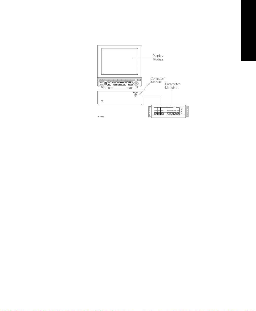
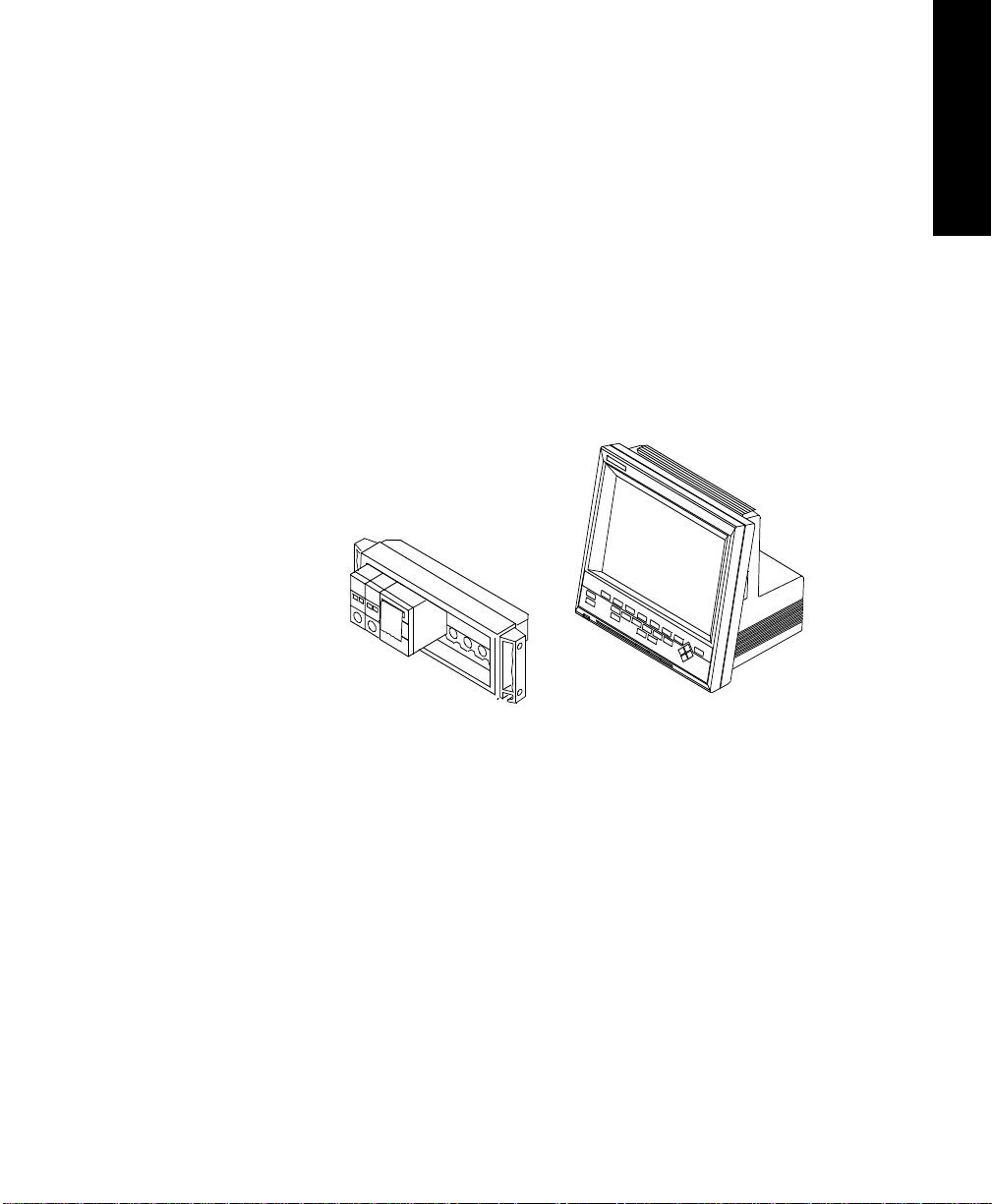
M1167/77A System
Display Module M1095A 10.4” Flatsc reen Display
Computer Module M1046B Computer Module
Parameter Mo dules Satellite Rack
Introduction
and V26 Monitors
The Agilent CMS, V24
The Agilent CMS, V24 and V26 Monitors
1-3
Page 28
The Agilent CMS, V24
Introduction
and V26 Monitors
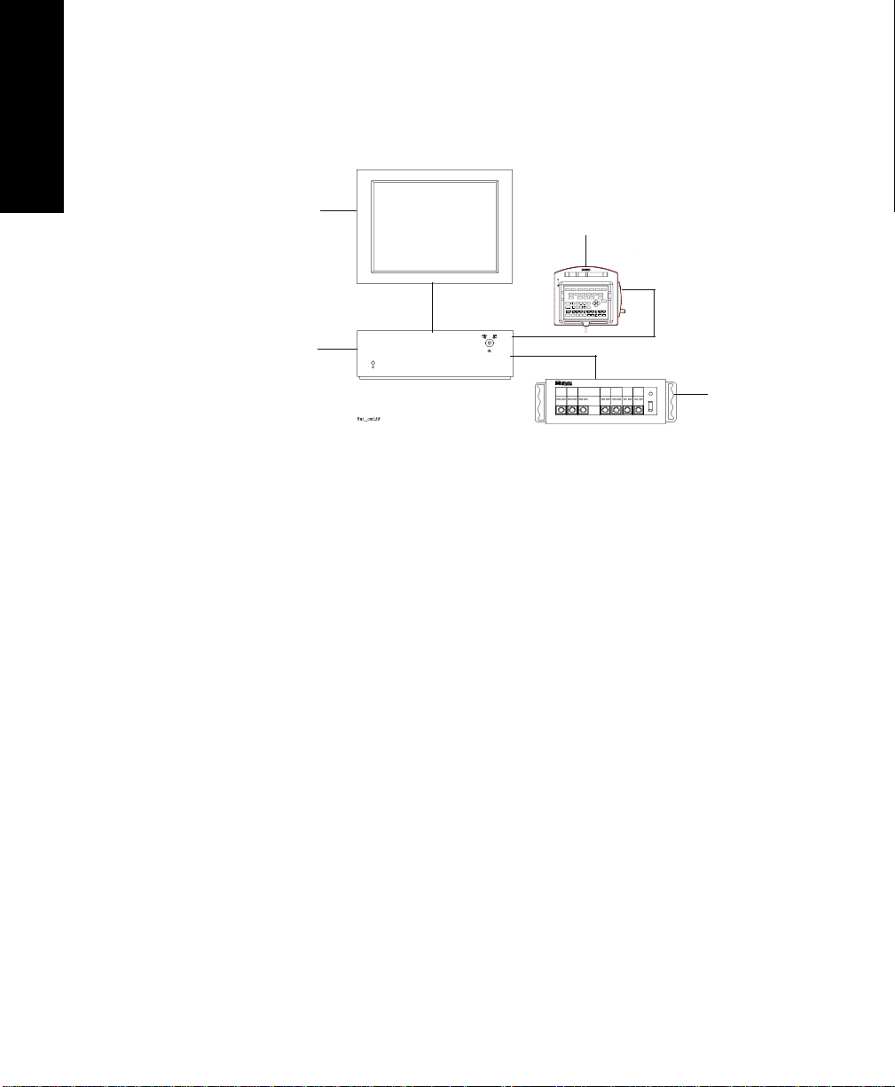
M1167/77A System with External Alarm Device
XGA Display
External Alarm Device
Computer
Module
Parameter
Modules
Display Module ITE Display of choice
Computer Module M1046B Computer Module
Parameter Mo dules Satellite Rack
a. Agilent offers the M1167/77A #H05 (XGA Touchscreen display con-
figuration). The display is also available separately under the order
number M1097A #A02.
1-4 The Agilent CMS, V24 and V26 Monitors
a
Page 29
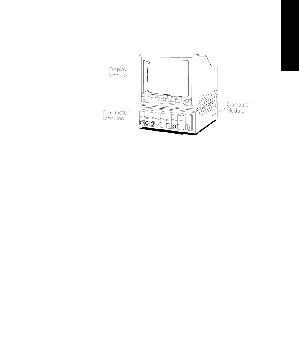
M1165/75A and M1166/76A System
Display Module M1094A/B/92A 14” CRT Display
Computer Module M1046A Computer Module
Parameter Mo dules Integral and/or Satellite Rack
Introduction
and V26 Monitors
The Agilent CMS, V24
Model Types
All system types are also av ailable as a choice of three diff erent model
types:
Full Title Abbreviation
The Agilent Component Monitoring System Agilent CMS
The Agilent Component Monitoring System for
Agilent ACMS
Anesthesia Care
The Agilent Component Monitoring System for
Agilent NCMS
Neonatal Care
Note—
In this manual, the system will be referred to as the Agilent CMS,
the Agilent ACMS and the Agilent NCMS.
The Agilent CMS, V24 and V26 Monitors
1-5
Page 30
Introduction
The Agilent CMS, V24
Display
Modules
and V26 Monitors
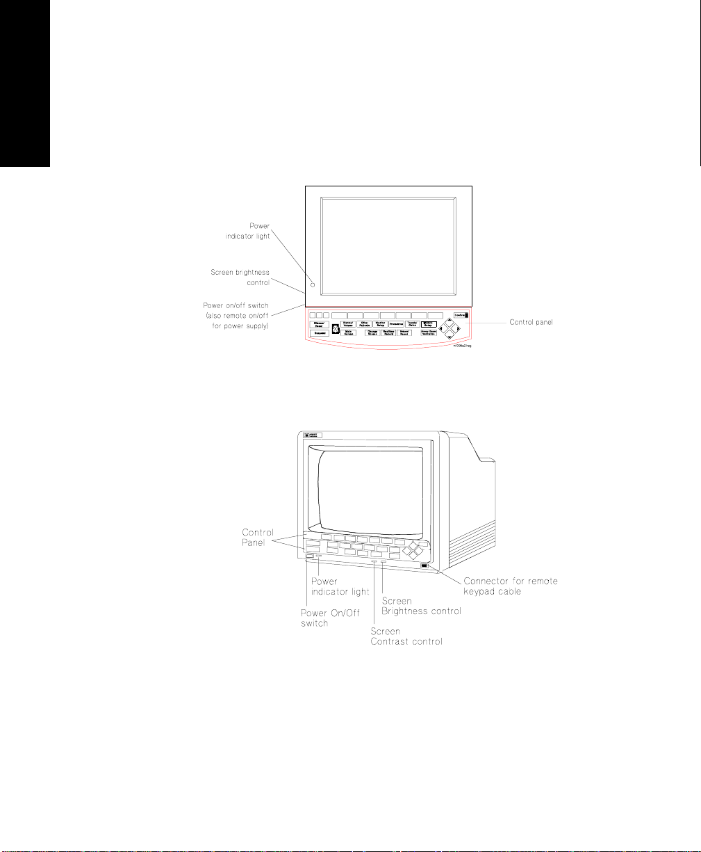
Below are labeled diagrams of the display modules provided by Agilent
Technologies. The control panel is described in more detail in the
following sections
.
M1095A Flatscreen Display Module
M1092A / M1094B CRT Display Module
1-6 The Agilent CMS, V24 and V26 Monitors
Page 31
Introduction
Agilent V24
and V26
Each Agilent V24 and V26 monitor consists of two individual parts.
1. One of two types of Displa y Modules, depending on the particular
model monitor you ha ve purchased—either:
a. A monochrome display with control panel supporting the
Agilent V24, or
b. A color flat pane l display with control panel supporting the
Agilent V24C, the Agilent V24CT, the Agilent V26C and the
Agilent V26CT.
2. The Rack with Parameter Modules
and V26 Monitors
The Agilent CMS, V24
The Agilent Models V24, V24C and V26C are powered by connection to an
AC power supply. The Agilent Models V24CT and V26CT can be powered
by rechargeable batteries or by connection to an AC power supply. See
“Agilent V26CT/V24CT Power Supply” on page 1-14.
The Agilent CMS, V24 and V26 Monitors
1-7
Page 32

Introduction
The Agilent CMS, V24
Control
Panel
and V26 Monitors
Softkeys
Hardkeys
The control panel consists of softkeys, hardkeys and alarm lamps.
The softkeys perform multiple fu nctions. Their functions correspond to
the labels displayed at the bottom of the screen. When no softkey labels
are on the screen, the softkeys do not function.
The hardkeys have only one function defined by the label on the key.
The hardkeys are labeled in blue. Each one of these keys gets you into a
level where adjustments and changes can be made or performs an
immediate action. The keys are labeled according to their function, for
example, key allows you to start a recording of a
waveform.
Note—
Device, the handheld keypad can be used to operate the system and to
enter data. It contains all the hardkeys and softkeys available on the
control panel of the othe r systems.
Realtime Record
If you are using the M1167/77A system with the External Alarm
1-8 The Agilent CMS, V24 and V26 Monitors
Page 33

Introduction
Alarm Lamps
Alarm Lamps
Silence/
Reset
Suspend
The alarm lamps are lit when a red or yellow alarm condition exists.
CMS Control Panel
Other
*
*
*
Main
Screen
Alarms Suspended Lamp
Patients
Monitor
Setup
Realtime
Record
Procedures
*
Delayed
Record
Trends/
Calcs
Module Alarms
Setup
*
Confirm
and V26 Monitors
The Agilent CMS, V24
*
V24 and V26 Control Panel
Note—
Earlier versions of the Agilen t V24 feature a key instead of
the key.
Trends/Calcs
The Agilent CMS, V24 and V26 Monitors
Trends
1-9
Page 34

Introduction
and V26 Monitors
The Agilent CMS, V24
The
Handheld
Keypad
(Agilent CMS only):
The handheld keypad consists of the same softkeys and hardkeys that
are available on the con trol panel. In addition, the keypad provides data
entry keys which enable you to enter letters, numbers, punctuation
marks, and arithmetic symbols.
Note—
The handheld keypad is the main means of operating the
M1167/77A System with External Alarm Device. Do not remove the
keypad from systems with touch or mouse/trackball operation as it is
still required to perform certain tasks.
Softkeys and
Hardkeys
Data Entry
Keys
1-10 The Agilent CMS, V24 and V26 Monitors
The softkeys and hardkeys on the keypad are in the same relative
position and operate in the sam e manner as the keys on the control
panel.
The data entry keys are located on the bottom half of the keypad.
Page 35

Introduction
Shift
• To enter numbers and arithmetic symbols (labeled in white), simply
press the keys you want.
• To enter letters and punctuation marks (labeled in blue), press the
key. The lamp in the key lights up and remains on
Shift Shift
until is pressed again. The softkeys and hardkeys work as
normal.
and V26 Monitors
The Agilent CMS, V24
External
Alarm
Device
(Agilent CMS only):
Since the External Alarm Device is used only with commercially available
ITE displays that do not have a control panel, it contains all the alarm
lamps, the Alarms Suspended Lamp and the loudspeaker. It does not
contain any hardkeys or softkeys and therefore can only be used in
conjunction with the Handheld Keypad. The Handheld Keypad can be
mounted onto the External Alarm Device as illustra ted below.
The Agilent CMS, V24 and V26 Monitors
1-11
Page 36

Introduction
Procedures
and V26 Monitors
The Agilent CMS, V24
Hardkey
Functions
Silence/Reset
- press to silence an alarm or alarms that are sounding
or, if alarms are latching, to reset them.
Suspend
- press to suspend or switch on all alarms. The current state
is indicated by the Alarm Suspend Lamp.
Main Screen
Change Screen
- press to return to the main monitoring screen.
- (Agilent CMS only) press to change between
screen layouts or to access a 2nd or 3rd display. You can also freeze any
wave movement on the screen (INOPs, alarms and numerics are not
affected).
Realtime Record
- press to record pre-selected waves onto a system
recorder or a bedside recorder.
Delayed Record
- press to record pre-selected waveforms that are no
longer on the monitor screen.
Alarms
- press to enable you to suspend or switch on ala rms, se t and
review alarm limits, enter Monitor Standby, or set the alarm volume.
Other Patients
- press to enable you to view data from other beds in
your group.
Monitor Setup
- press to enable you to pre-select certain system
characteristics.
1-12 The Agilent CMS, V24 and V26 Monitors
- press to enable you to set up and per form procedures
such as Cardiac Output, Wedge Pressure (Agilent CMS only), ST
analysis, Drug Calculations, ad mit and discharge patients, or end a
particular patient case and transfer patient data.
Trends/Calcs
- press to enable you to view vital signs and graphical
trends, make and review calculations, print reports and mark events to
view in graphs.
Module Setup
- press to enable you to change or adjust parameter
settings, switch parameters on or off, or set up parameters.
Arrow
Keys
Page 37

Introduction
Confirm
The arrow keys consist of up/down/left/right keys. They only function
when illuminated. The arrow keys allow you to move between areas on
operating screens to enable you to change or adjust settings, perform
procedures, or make changes to the screen display.
Key
This key functions only when it is illuminated. A prompt message “...press
CONFIRM...” appears on the screen when you need to use it.
and V26 Monitors
The Agilent CMS, V24
Airway Gases/Ventilation
- (Agilent CMS only) Press to view airway
gases or ventilator waves and numerics.
The Agilent CMS, V24 and V26 Monitors
1-13
Page 38

Agilent V26CT/V24CT Power Supply
Agilent V26CT/V24CT Power Supply
and V26 Monitors
The Agilent CMS, V24
The Agilent Models V24 CT and V26CT are powered by an external AC
(line power) or by their own internal battery power supply. Your
monitoring needs will determine which power source is used. We
recommend that you plug the monitor into line or AC power whenever
the monitor is not being moved or used, or for long term bedside
monitoring. When transporting a patient or when monitoring in a remote
area, where AC power is not feasible, use battery power.
WarningWarning
Do not disconnect the power cord from the monitor and leave it
connected to the AC power source. This could cause damage to
the power cord. Instead, keep the power cord connected to the
monitor and unplug it from the AC power source.
The power cord must be inspected periodically for cracks or
exposed metal parts. Replace immed iately if there are any
cracks, exposed metal parts, or any ot her signs of wear and tear.
Battery
Power
Supply
1-14 The Agilent CMS, V24 and V26 Monitors
The Agilent Models V24CT and V26 CT can be powered by 1 or 2 sealed
lead-acid batteries with 12 Volt 2.3 Amp-Hour capacity. The rate of
battery discharge is de pendent on temperature an d power load. The
power load is a function of the number and type of parameter modules
as well as parameter settings being used. The battery life for the Agilent
Models V24CT and V26CT ranges from approximately 30 minutes fo r a
fully loaded system operating on one battery to:
• 1 hour for a fully loaded system operating on two batteries when
loaded with the following parameter modules:
ECG/Resp, NBP, SpO
• 1 hour 15 minutes for a minima lly loaded system operating on two
batteries when loaded with the following parameter modules :
ECG/Resp, NBP, SpO
We recommend you use 2 fully charged batteries to g et the optimum
battery life when using the battery pow er supply.
, Pressure, Recorder and
2
, Pressure.
2
Page 39

Agilent V26CT/V24CT Power Supply
Battery
Specifications
• 1 or 2 lead-acid batteries.
• 12 Volt 2.3 Amp-hour capacity.
• Up to 1.25 hours battery capacity typical on full charge at 25°C,
depending on modules used in the product.
Note—
Charging time is 4 hours to 90 % of full capacity if the monitor is off.
16 hours to 90% of full capacity if th e monitor is on.
Confirm
Trends/
Calc
Delayed
Record
Note—
When AC is connected and the monitor is on, the Battery Charge
Module
Setup
Battery
Charging
Battery
Charged
AC
Power
LEDs may take some time to cyc l e to the appropriate charge indication
and may underreport battery capacity during this se tting period. Use the
fuel guage rather than the Batt er y Charg e LEDs du rin g th is pe ri o d to
estimate battery capacity or turn the monitor off to accelerate the charge
setting time.
and V26 Monitors
The Agilent CMS, V24
See Chapter 12, “Battery Information (Agilent V24 and V26 only)” for
additional information on battery operation and Battery Charge LEDs and
indicators.
The Agilent CMS, V24 and V26 Monitors
1-15
Page 40

Parameter Modules
Parameter Modules
and V26 Monitors
The Agilent CMS, V24
The parameter modules have one or more hardkeys on the front. The
key labeled with the parame ter name is called the Setup key, which ge ts
you directly into the setup screen for that parameter. When you press
the Setup key on the front of the module, and get into the parameter
setup window or task window , a light appears above the key.
The connector socket on the front of each module is the same color as
the corresponding connector plug on the transducer or patient cable.
M1001B
ECG
Light for
setup key
ECG
Parameter
setup key
T
80x80
Connector for
patient cable
or transducer
Note—
If a “T” is present on the front of a module, certain pa rameter
settings may be transferred with t hat module when it is moved from one
rack to another. This behavior is dependent on a setting made in a
1-16 The Agilent CMS, V24 and V26 Monitors
12
PIN
Page 41

Parameter Modules
special Service Mode, either by your biomedical engineering department
or the Agilent service engineer. You can find a description of this behavior
(called “Parameter Settings Transfer”) in Chapter 3.
Parameter modules can be plugged into the following types of rack:
Rack Type Mounting Comments
Agilent CMS
and V26 Monitors
The Agilent CMS, V24
Integral Rack This is fitted to the front of
the M1046A computer
module.
Satellite Rack You can have one or more
satellite racks attached to
an I.V. pole, bedside or
wall.
Cannot be used with
the M1167/77A CMS
System. 8-slot rack.
Can be used with all
CMS Systems.
Available as 6-slot or
8-slot rack.
Agilent V24 and V26
8-slot Satellite
Rack
(Standard)
Same as Satellite Rack for
CMS.
Only one Satellite
Rack can be used
with an Agilent V24
or V26 Monitor.
6-slot Satellite
Rack
(Optional)
Same as Satellite Rack for
CMS.
This can also be mounted
to the back of the M1205A
V24CT and V26 CT
Monitors
Caution
When the rack is mounted in close proximity to any intravenous infusion
equipment, do not let salin e solution get onto the rack or parameter
modules. Severe damage to the equipment can result if saline solution
leaks into the c onnectors at the rear of the modules.
The Agilent CMS, V24 and V26 Monitors
1-17
Page 42

Parameter Modules
and V26 Monitors
The Agilent CMS, V24
You can plug the parameter modules into the rack and re move them as
you require them. The num ber of modules you can plug in depends on
the type of rack and the model of monitor you have orde red.
For most types of parameter modu les, the system allows only one of
each type per patient (ECG, for example). Other types of modules allow
more than one per patient (Invasive Pressure, for example).
If too many modules or an unsupported module are plugged in, a
message detailing where the extra module is, appe ars in the system
message field:
Currently ignored module in rack position
R-P
where:
R is the number of the rack
(e.g. 1=integral rack, 2=first satellite rack, ...
or 1=first satellite rack, 2=second satellite rack , ...
P is the slot number in that rack
(counted from left to right)
The message
Unrecognized module in rack position R-P
is displayed if an unknown module is plugged into the rack.
Note—
Since the Agilent V24 and V26 Monitors only support one module
rack, R will always be 1.
1-18 The Agilent CMS, V24 and V26 Monitors
Page 43

Operating Levels
Operating Levels
There are three types of screens which you will see on the display
module. The three types of screen and the interconnections between
them are show n below.
Standard
Display
1st Level
Control
Panel
Selection
Window
and V26 Monitors
The Agilent CMS, V24
2nd Level
Task
Window
The Agilent CMS, V24 and V26 Monitors
1-19
Page 44

Operating Levels
Main Screen
Main Screen This display shows the waveforms and numerical readouts of the
parameters you have chosen to monitor, alarms, INOP messages, bed
and V26 Monitors
The Agilent CMS, V24
label, date and time, and arrhythmia messages (when a ssigned).
You can configure the number and position of the waveforms on the
display screen. The nume rics are aligned with the corresponding waves.
The numeric information is updated every two seconds. With the color
model, the nume ric appears in the sa me color thet you have assigned to
the corresponding waveform.
The hardkey always returns you directly to the Main
Screen.
1-20 The Agilent CMS, V24 and V26 Monitors
Note—
The Main Screen of the Agilent V24 and V26 Monitors includes
Alarm Volume Control and QR S Volume Control Bars (see figure be low)
Page 45

Operating Levels
CHANNEL #1
LAYOUT: #1 NON-OVERLAP
CHANNEL #2
CHANNEL#3
CHANNEL #4
II
F HR
ABP
PLETH
CO
2
1mV
120
0
SpO
SQI
2
40
0
Alarm Vol 165
ICU Adult 10 JAN 95 20:05
QRS Vol 150
HR
70
ST1
ST2
ABP
135/72 (94)
PAP
34/16
(23)
SpO
2
-0.2
0.3
PULSE
70
97
ETCO
2
20
0
IMCO
AWRR
NBP
2
37
115/65
(81)
19:47
NUMERICS
and V26 Monitors
The Agilent CMS, V24
The Agilent CMS, V24 and V26 Monitors
1-21
Page 46

Operating Levels
and V26 Monitors
The Agilent CMS, V24
Selection
Window
This is the first operating level where you can choose a specific activity
or function.
You get into a Selection Window by pressing one of the blue-labeled
hardkeys on the control panel.
When you get into the Selectio n Window the bottom line is always
active. This is indicated by a bar below the keys and the yellow labeling.
The selection can be changed within the Selection Window one line at a
time. For information on how to change the selection see page 1-24.
There is also an arrow symbol in the Window that moves along the
selected line when the cursor keys are pressed. To enter the Task
Window to which the arrow is pointing, press .
Confirm
1-22 The Agilent CMS, V24 and V26 Monitors
Page 47

Operating Levels
Task
Window
This is the second operating level, which allows you to make changes or
adjustments to the parameters and screen displays, or to perform
procedures. Each paramete r or procedure has a series of Task Windows.
There are tw o ways to get into the second operating level:
via the Selection Window ,
or for parameters:
by pressing the Setup key on the parameter module.
and V26 Monitors
The Agilent CMS, V24
The Agilent CMS, V24 and V26 Monitors
1-23
Page 48

Operating Levels
Getting into
the
Operating
and V26 Monitors
Levels
The Agilent CMS, V24
Before you can start to make adjustments or changes to the parameters
or perform a proced ure, you need to know how to get into the operating
levels and how to navigate through the selections. Follow the
procedures below to get int o the Selection and Task Windows.
Selection Window
1. Press the blue-labeled hardkey for the function you require.
2. When you get into a Selection Window, the bottom line is always
active. Select the line with the parameter or function you require,
by pressing the same hard ke y aga in th at go t yo u i n to the sel e cti o n
window, or use the arrow keys if t hey are illuminated.
3. Press either the softkey corresponding to the parameter or
function you require or . This gets you into the Task
Window.
For example, to get into the Noninvasive Blood Pressure (NBP) Task
Window:
1. Press the hardkey
2. If it is not already active, select the line containing NBP by
pressing again.
3. Press the softkey to get into the Noninvasive Blood
Pressure Task Window.
Module Setup
Confirm
Module Setup
NBP
Task Window
There are two ways to get into a parameter Task Window, either:
via the Selection Window,
or
by pressing the Setup key on the parameter module w hich gets
you directly into the Task Window.
1-24 The Agilent CMS, V24 and V26 Monitors
Page 49

Operating Levels
Getting into other Task Windows for functions like Other Patients or
Monitor Setup is only possible via the Selection Window. In the Task
Window there are separate keys. The selections that are currently active
for the parameter or function you have chosen are indicated by yellow
labeling. In addition the selected keys appear to be “pushed in” on the
screen.
There are two reasons for changing the selection in the Task Windows:
you will either want to move to the ne xt Task Window, or make an
adjustment to a setting.
1. To move to the next Task Window, press the softkey for the
function you require, for example . This gets you
Filter/Mon/Diag
into the Filter/Mon/Diag Task Window where you can make any
necessary adjustments.
2. To make an adjustment, change the selection by pressing the
softkey for that window a gain, until the adjustment or change you
want is active, or use the arrow keys if they are illuminated.
and V26 Monitors
The Agilent CMS, V24
The Agilent CMS, V24 and V26 Monitors
1-25
Page 50

Touch or Mouse/Trackball Operation (CMS only)
Touch or Mouse/Trackball Operation (CMS only)
and V26 Monitors
The Agilent CMS, V24
The M1167A/77A systems also allow connection of XGA displays,
enabling touch (requ ires touchscreen displays), mou se or trackball
operation of the monitor. Since these displays do not contain a control
panel, there are slight differences in operating the system. The following
sections contain the instr uctions specific to touch, mouse or trackball
operation.
Main Screen The layout of the main screen is basically the same as with other CMS
systems, with the only exception that it contains three additional
buttons: the Silence/Reset button, the Suspend button (both in the upper
right corne r of the display) and the Control Panel button (in the lower
right corner of the di splay).These buttons are touch-responsive and can
be used alternatively to the hardkeys of the control panel or the
handheld keypad..
Note—
Do not remove the keypad from systems with touch or mouse/
trackball operation as it is still required to perform certain tasks.
1-26 The Agilent CMS, V24 and V26 Monitors
Silence/
Reset
Suspend
Control
Panel
Page 51

Touch or Mouse/Trackball Operation (CM S only)
Control
Panel Task
Window
The Control Panel Task Window contains most of the hardke ys found on
the control panel of non-touch systems. See “Hardkey Funct ions” on page
1-12 for detailed descriptions of these keys. You can a cc ess the Control
Panel Task Window by touching the Control Panel symbol in the lower
right corner of the main screen display.
Control Panel Task Window
and V26 Monitors
The Agilent CMS, V24
General
Touch/
Mouse/
Trackball
Operation
If a touch-responsive object or area of the screen is selected (either by
touch or by mouseclick), a whi te ‘+’ appears and the area is surrounded
by a white frame. In addition, an audible click is issued. The white frame
disappears automatically when the object is released. If an object or area
of the screen that is not touch-responsive is touched, a white ‘x’ appears
in the selected area.
Note—
When using a mouse/trackball, the white ‘+’ and ‘x’ signs appear,
wherever the mouse/trackball pointer is currently located. This indicates
touch-responsive areas before they are actually se lected by mouseclick.
The Agilent CMS, V24 and V26 Monitors
1-27
Page 52

Touch or Mouse/Trackball Operation (CMS only)
The Agilent CMS, V24
Touch-
Touch-respon sive objects and areas of the screen include:
Responsive
and V26 Monitors
Objects
• Numerics and Waves - When a numeric or wave is selected, the
respective parameter setup window opens up.
• Alarms/INOP messages - Selecting an Alarm or INOP Message
opens the alarm messages window.
• Task Windows/Selection Windows - All softkeys displayed in
Task Windows and Selection Windows a re touch-responsive.
When a Task Window/Selection Wi ndow is open, a sel ectio n of any
area outside this window (except the Silence/Rese t and Suspend
keys) will close the task window. Selecting the black x in the
corner of the Task Window label also closes the Window. Closing
a Task Window returns you to the Main Screen.
• Items/Selections - All Items and all Selections within Task
Windows can be directly selected by touch or mouseclick withou t
the Select Item softkey or the arrow keys.
• Arrow Keys - Depending on the application, buttons are provided
to perform the task of the arrow ke ys.
• Confirm Button - A confirm button is displayed in the lower right
corner of the task window everytime a confirm is required.
• Application Windows - Split Screen, oxyCRG and CSA Display
contain touch-responsive areas which lead to the re spective task
windows. Please refer to Chapter 3 of this manual for further
details.
• Application-specific buttons - Touch/Mouse/Trackball
Operation has special implications for the Vital Signs, Graph
Trends and Calculation Task Windows (see Chapter 8 Trends and
Calculations for details), for the Patient Admit Task Window (see
Chapter 7 Admit/Discharge/End Case for details), for the ST
Analysis Task Window (see Chapter 14 ECG and ECG/Respiration
Module Section for details) and for defining screen labels and
adjusting the date and time (see Chapter 3 Setting up your
Monitor for details).
1-28 The Agilent CMS, V24 and V26 Monitors
Page 53

Touch or Mouse/Trackball Operation (CM S only)
Next Item
Back
Alphanumeric
Entries
A Touchboard can be accessed when alphanumerical data needs to be
entered . This is an alternative to the entry of data with the handheld
keypad. The Touch board can be acti va ted wi t h t he “ T ouch Board” softkey
e.g. from the Patient Admit Task Window.
The Touchboard Task Window cont ains a subtitle which references the
Task Window from which the Touchboard was accessed. Data entry can
be performed for one item at a time.
Press to save edited data.
Press or to navigate through the editable
Previous Item
items of the Task Window the Touchboard was accessed from.
Press to return to the Task Window the Touchboard was accessed
from.
The Agilent CMS, V24 and V26 Monitors
1-29
Page 54

Touch or Mouse/Trackball Operation (CMS only)
Disabling
Touch/
Mouse/
Trackball
Operation
In order to prevent unint ended or uncontrolled operations of the
monitor, to uch operation must be disabled while cl eaning the
touchscreen. To disable touch and mouse/trackball operation press and
hold or click and hold the control panel button in the lower right corner
of the main screen for at least fo ur seconds. A padlock icon over the
control panel button indicates when touch and mou se/trackball
operation is disabled. To re-enable touch and mouse/tr ackball operation
press and hold or click and hold the padlock icon for at least four
seconds. The control panel button w ill reappear.
Note—
If a task window is opened or t he monitor is put in standby mode
via the handheld keypad while touch and mouse/trackball operation is
disabled, touch any area of the screen to return to the main screen. The
padlock icon will be displayed.
1-30 The Agilent CMS, V24 and V26 Monitors
Page 55

The CMS Computer Modules
The signals from the parameters being monitored are transmitted to the
computer module, where they are processed and then displayed on the
screen as waveforms and numerical readouts.
The CMS Computer Modules
M1046A
Computer
Module
The M1046A Computer Module is for use with the Agilent M1165/66A and
the Agilent M1175/76A CMS.
Maximum Voltages
ECG Output and Defib. Marker Input 3.2 V p-p
Connector for satellite rack 60 V
The parameter module rack can be attached to the computer module, or a
blank panel can be fitted to the computer module if you want to use a
satellite parameter module rac k.
The Agilent CMS, V24 and V26 Monitors
1-31
Page 56

The CMS Computer Modules
M1046B
Computer
Module
The M1046B Computer Module is for use with the Agilent M1167/77A
CMS.
Maximum Voltage
ECG Output and Defib. Marker Input 3.2 V p-p
The parameter modules are inserted into one or several satellite racks.
They cannot be attached to the front of the computer module.
ECG Output
Applies to both the M1046A and M1046B Computer Modules.
and
Defibrillator
Marker Input
1-32 The Agilent CMS, V24 and V26 Monitors
The ECG output and defibrillator marker input connector on the
computer module is used during cardioversion to provide an ECG
waveform for synchronizing a defibrillator. It is also used to receive a
marker pulse from the defibrilla tor for indicating the defibrillator
discharge in the ECG waveform on the monitor display.
If you are using an Agilent defibrillator without a built-in recorde r, the
marker pulse from the defibrilla tor is returned to the monitor. If the
Agilent defibrillator has a built-in recorder, then the marker pulse is
returned to that recorder rather than to the monitor. The ECG output
can also be used for other ap plications, such as synchronizing intra aortic balloon pump systems.
Page 57

The Agilent V24 and V26 Parameter Module Rack
The Agilent V24 and V26 Parameter Module Rack
The Agilent V24 and V26 parameter module rack is attached to the display
module by a cable t o a con n ect or on th e l eft side of the display modu l e. I n
addition, the Agilent Models V24CT and V26CT allow you to dock a 6-slot
rack directly to the mainframe.
WarningWarning
Do not connect a second rack by a cable when using the Agilent
Model V24CT or V26CT with a 6 wide rack docked to the
mainframe. Docking a second rack by a cable may disrupt module
communication.
The signals from the parameters being monitored are transmitted to the
internal computer, where they are processed and then displayed on the
screen as waveforms and numerical readouts.
The Agilent CMS, V24 and V26 Monitors
1-33
Page 58

Operating Rules to Remember
Operating Rules to Remember
• Pressing key always returns you to the Main Screen.
• To get into a Selection Window press a hardkey.
• What is labeled in yellow and a ppears “pushed in” is active.
• Softkeys function only in the Selection and Task Windows (with
the exception of the Alarm Volume Control and the QRS Tone
Volume Control on the Agilent V24 and V26 Monitors).
• The parameter module Setup key gets you directly into a Task
Window.
• The arrow key s and key are illuminated when available
for use.
Main Screen
Confirm
1-34 The Agilent CMS, V24 and V26 Monitors
Page 59

Performance Specifications of the Agilent Displays
Performance Specifications of the Agilent Displays
M1095A
Flatscreen
Display
M1094A/B
and M1092A
CRT Display
Useful Screen:
(±5% unless otherwise noted)
Pixel Size 0.33 mm x 0.33 mm
Storage Time at 25 mm/sec 5.5 seconds
Trace Speeds 6.25, 12.5, 25, 50 mm/sec ±10%
Useful Screen:
(±5% unless otherwise noted)
Pixel Size 0.22 mm x 0.35 mm
Storage Time at 25 mm/sec 6 seconds
158 mm x 211 mm (6.2” x 8.3”)
180 mm x 225 mm (7.1” x 8.9”)
M1097A
#A02 XGA
Flatscreen
Display
Trace Speeds 6.25, 12.5, 25, 50 mm/sec ±10%
Useful Screen:
(±5% unless otherwise noted)
Pixel Size 0.297 mm x 0.297 mm
304.1 mm x 228.1mm (12” x 9”)
The Agilent CMS, V24 and V26 Monitors
1-35
Page 60

Using an ITE Display
Using an ITE Display
The M1167A/77A CMS provide s means for customers to use ITE
displays. There are sev eral re stri ctions associate d wi th thi s optio n. Si nce
the display is used as part of a medical device within the patient vicinity,
there are additiona l requirements to be fulfilled in order to be in
compliance with the European Council Directive 93/42/EEC (Medical
Device Directive) and with FDA recognized consensus standards:
•Safety
•EMC
• Performance Requirements
Safety 1. The display must either comply with the requirements of the:
EN60601-1 +A1 +A2 {IEC601-1 +A1 +A2}, or
it must conform to the requirements of an IEC XXX electrical
safety standard and fulfill specific requirements according to the
EN60601-1-1 +A1 {IEC601- 1-1 + A1} to provi d e th e same level of
safety as EN60601-1 {IEC601-1} :
– The display must be constructed or protected so t hat spillage
of liquids does no t wet pa rt s of the di spl ay whi ch may cau se a
safety hazard (IEC601-1; 44.3) .
– The ITE display must be used with an isolation transformer
(e.g. Agilent M1389A), if the enclosure leakage current
exceeds the requirements of EN60601-1/IEC601-1 (normal
and single fault condition). The power cable must be secured
so that the transformer cannot be disconnected without the
use of a tool.
2. A test of the Enclosure Leakage Current (normal and single fault
condition) of the complete system, including the display, has to be
performed and documented.
1-36 The Agilent CMS, V24 and V26 Monitors
Page 61

Using an ITE Display
EMC 1. The display must either fulfill the requirements of the EN60601-1-2
{IEC 601-1-2}, or
it must conform to the requirements of the EMC stand ard for ITE
devices, EN50082-1: 1997 and EN50081-1 / CISPR 22.
2. The video cable between M1167A/77A CMS and the ITE display
must not exceed a length of 3.0m. For cables exceeding 3.0m EMC
testing according to IEC 801-4:1988 has to be done.
Performance
Requirements
Specification Requirement or Value Units
Resolution (pixel addressability) 1024 x 768 Dots x lines
Vertical Refresh Rate 60 Hz (non-interlaced)
Red, Green and Blue Vide o Inputs ~0.7 V p-p
Vertical & Horizontal Multi-Sync Inputs 5 V TTL
Video-Cable Connec to r HD15male
Agilent cannot assure compliance with the ANSI/AAMI EC-13 Standard
for Cardiac Monitors, H ea rtrate Meters and Alarms when using ITE
displays. Compliance with the ECG aspect ration and 25 mm/s
sweep-speed specifications c an only be assured when using the Agilent
Displays M1092A, M1094B and M1095A. In addition, the following display
specifications are recommended:
±10%
The Agilent CMS, V24 and V26 Monitors
1-37
Page 62

Using an ITE Display
1-38 The Agilent CMS, V24 and V26 Monitors
Page 63

Getting Started
Now that you have be en introduced to the monitor you are
probably ready to start using it. This chapter will help you get
started. It contains the following sections:
• Setting up the Monitor (Agilent V24 and V26 only). . . . . . 2-2
• Setting up the Parameter Modules . . . . . . . . . . . . . . . . . . . 2-5
• Attaching the Patient . . . . . . . . . . . . . . . . . . . . . . . . . . . . . . 2-6
2
Getting Started 2-1
Page 64

Setting up the Monitor (Agilent V24 and V26 only)
Setting up the Monitor (Agilent V24 and V26 only)
1. Attach the parameter module rack to the display module by a
cable to the connector on the left side of the display module. If you
are using the Agilent Model V24CT or V26CT you can attach the 6slot rack to the back of the mainframe display without the n eed for
a cable. The two components will snap or dock together.
Getting Started
2-2 Getting Started
Page 65
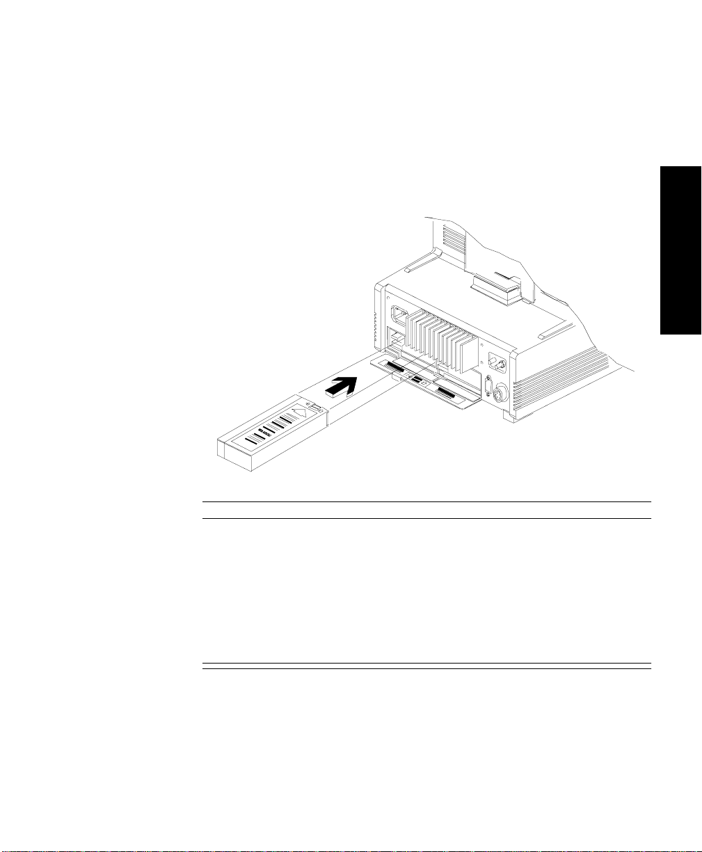
Setting up the Monitor (Agilent V24 and V26 only)
2. If you are using the Agilent Model V24CT and V26CT and the
batteries are not already in place, insert 2 Agilent 40488A 12 Volt 2.3
Amp-hour sealed lead-acid batteries into the spring-loaded battery
door in the back of the monitor. The batteries should be inserted
with the grey Agilent battery label facing upwards and the contacts
pointing into the monitor. The batteries will snap or click into place
when properly inserted.
0
0
0
0
0
A
Getting Started
Caution
Agilent Technologies recommends you fully charge the batteries before
using the Agilent Models V24CT orV 26CT for the first time. Plug the
monitor into an AC power supply (line power) for an initial charging
cycle. When the monitor is plug ged in and the power is off, it takes
approximately four hours for the batteries to reach a charge of 90%
capacity and nine hours for the batteries to be fully charged. If the
monitor is plugged in and the power and external battery charger is on, it
takes approximately 16 hours to charge the batteries.
3. If using an AC power supply, plug the power co rd into the power
source.
Getting Started
2-3
Page 66

Setting up the Monitor (Agilent V24 and V26 only)
4. Switch on the system using the power On\Off switch. A self test is
then performed.
WarningWarning
Connecting the Agilent monitoring network (S DN) cable when the
product is powered on is not supported. Error codes and Agilent
monitoring network (SDN) interface lock-up may occur. Power cycling
the product will recover the product. No permanent damage will result.
To prevent unintentional disruption in monitoring, be sure the SDN
interface cable is properly secured at both ends when connecting to the
Agilent monitoring network (SDN).
Getting Started
2-4 Getting Started
Page 67

Setting up the Parameter Modules
1. Decide which parameters you want to monitor.
2. Make sure the appropriate modules are plugged into the rack. If not,
insert the module into the rack until the lever on the base of the
module clicks into place. To remove a module, press the lever
upwards and pull the module out. (See diagram below.)
Setting up the Parameter Modules
Getting Started
3. Check that you have the correct patient cables and transducers
plugged into the modules. The module connectors are color-coded
to the patient cables and transducers, for easy identification.
Your monitor may have Parameter Settings Transfer set ON. To
understand the effect this has when using modules with th e “T” label, turn
to Parameter Settings Transfer in Chapter 3.
Getting Started
2-5
Page 68

Attaching the Patient
Attaching the Patient
Getting Started
1. Attach the electrodes, probes, transducers, and insert pressure
catheters as required for monitoring the patient.
2. Connect the electrod es, p rob es an d tr an sdu c ers to the appropriate
modules.
After less than 10 or 20 seconds you should see a display on the screen
similar to the one under “Main Screen” in Section 1. The number of
waveforms depends on the waveforms you have selected to have
displayed and also on the model of your system.
The numerics are aligned with the corresponding waveform.
2-6 Getting Started
Page 69

Attaching the Patient
Adjusting
Screen
Contrast
Agilent V24 and V26:
The brightness or contrast of the screen display can be adjusted by using
the dial located behind the edge of the display, on the lower right side of
the monitor. Th e Agilent V24 uses a contrast control. Agilent Models
V24C, V24CT, V26C and V26CT are equ ipped with a brightness control.
Make sure that all of the screen information is visible.
Getting Started
Screen Brightness Control
(Model 26/24C,
26/24CT)
Screen Contrast Control
(Model 24)
Agilent CMS:
The brightness and contrast of the screen display can be adjusted by
means of the two dials underneath the hardkeys.
Follow this procedure to achieve the optimum screen display:
1. Turn the brightness and contrast controls to their maximum
settings.
2. Slowly turn the brightness and contrast controls down to the lowest
acceptable position where the display can still be seen clearly. The
most acceptable position will be dependent upon the surrounding
light conditions. Please ensure tha t all the screen information is
visible.
Getting Started
2-7
Page 70

Attaching the Patient
Starting
Monitoring
Getting Started
The patient’s vital signs are now appearing on the screen. The preconfigured default set tings for the parameters and screen display, that
were set up at installation or have been stored in the module
(“Parameter Settings Transfer”), are active.
Screen
Messages
2-8 Getting Started
If you want to make changes to the screen display see the section
“Configuring the System”. If you want to make changes to the
parameter settings see the individual parameter se ctions.
Switch the system alarms ON (by pressing the key so that
the Alarm Suspend lam p goes out). The patient is now being monitored.
Two types of messages appear at the top of the display screen:
• Prompt messages - these instruct the user to perform an action
• Status messages - these give information about the current
situation. For instance:
“sync output not available, plug-in ECG module''
Suspend
Page 71

Attaching the Patient
this message stays as long as the ECG module is not plugged in.
Prompt and status messages are displayed either in the appropriate Task
Window, or at the top of the Main Display screen, depending on the
operating level.
On the Main Screen display the prompt and status messages are shown
below the alarm and INOP messages.
Prompt messages appear for 3 seconds.
Status message are displayed in rotation for 3 seconds each.
Reserving a
Channel
In the Task Window the prompt and status messages remain until the
appropriate user action is performed.
A parameter module may be turned OFF, but left in the r ac k. The empty
channel where the waveform should be still appears on the Main Screen.
There is no waveform, wavef orm label, or numeric. Another wave may
use its screen channel tempora rily, but will be discarded as soon as the
assigned wave is reactivated.
This ensures that particular waveforms can always be allocated to the
same place on the Main Screen, and avoids inconsistencies in the
waveform display of different patients in the same department.
Note—
If trend data for this patient is to be collected, old data from a
previous patient should be deleted. The old data will be automatically
deleted if the monitor has been shut off for three hours or more. See
“Discharging a Patient/Ending a Case” on page 7-9 for more information.
Getting Started
Getting Started
2-9
Page 72

Attaching the Patient
Power
Failure
Getting Started
Patient
Information
Center
If a power failure occurs, any alarm conditions that were stored in the
monitor will NOT be retained whe n power is restored. Settings such as
alarm limits stored in “T” modules ARE retained - see “Parameter
Settings Transfer” on page 3-61.
Caution
You are advised to check all the monitor settings after any power failure.
The monitor reacts according to the length of the power failure:
Less than 60 seconds Patient Data Management data and all
settings retained.
Less than 3 hours Patient Data Management data retained. All
settings revert to user defaults.
More than 3 hours Patient Data Management data not retained.
All settings revert to user defaults. Time
setting may be lost if not networked.
If the monitor is connected to a Patient Information Center PIC (Agilent
78504 and Agilent 785 08) an d you sel e ct th e sam e l ea d for EC G c hann el s
1 and 2, the wave is not displa yed in ch anne l 2 of the Patient In formati on
Center.
Monitor
Standby
2-10 Getting Started
If you want to stop patient monitoring, but keep all settings and Patien t
Data Management information, you can switch the monitor into
“Monitor Standby”:
1. Press or
2. Press .
All waves and numerics disappear from the display, and all monitoring is
suspended. The word “S tandby” appears in big letters on t he screen.
Alarms / Volume Alarms
Monitor Standby
Page 73

Attaching the Patient
Suspend
If your monitor is connected to an Agilent patient care system while the
monitor is in standby, no parameter data from your monitor is sent over
the system. Instead, a message indicating that your monitor is in
“Standby” is sent to other beds in the system, and is displayed at the
Central Station. If your bed is co nfigured to receive alarms, and anoth er
bed in the system goes into alarm, the status message “Other Bed in
Alarm” is displayed on your monitor. You will hear the overview prompt
tone (two double beeps), but the Alarm Bed Task Window will not be
displayed.
To resume monitoring, simply press one of the keys (except )
Suspend
on the control panel on the front of the display or on the handheld keypad
(Agilent CMS only). The cha nges and adjustments that you made to the
settings before going into Monitor Standby are retained. Patient Data
Management informat ion collected before going into Monitor Standby is
also retained.
As all monitoring is suspended, no patient data is collected while the
monitor is in Monitor Standby.
The hardkey operates as usual when you are in Monitor
Standby, so you can prepa re the monitor alarm capability before you
resume monitoring.
Getting Started
Getting Started
2-11
Page 74

Attaching the Patient
Getting Started
2-12 Getting Started
Page 75

Setting up your Monitor
This chapter describes the characteristics of your system that
can be changed during monitoring, using the
key. It includes the following sections:
• Changing Display Screens . . . . . . . . . . . . . . . . . . . . . . . . . . 3-2
• Selecting a Screen. . . . . . . . . . . . . . . . . . . . . . . . . . . . . . . . . 3-3
• What you Can Configure. . . . . . . . . . . . . . . . . . . . . . . . . . . . 3-5
• Changes to the Configuration . . . . . . . . . . . . . . . . . . . . . . . 3-6
• Assigning Waves to Screen Channels. . . . . . . . . . . . . . . . . 3-8
• Selecting the Number of Waves. . . . . . . . . . . . . . . . . . . . . 3-13
• Changing the Wave Overlap. . . . . . . . . . . . . . . . . . . . . . . . 3-14
• Selecting Realtime Wave Speeds. . . . . . . . . . . . . . . . . . . . 3-15
• Displaying Split Screen Trends . . . . . . . . . . . . . . . . . . . . . 3-22
• oxyCRG Display. . . . . . . . . . . . . . . . . . . . . . . . . . . . . . . . . . 3-25
• CSA Display (Agilent CMS only). . . . . . . . . . . . . . . . . . . . 3-28
• Configuring a Sec ond Independent Display (Agilent CMS
only) . . . . . . . . . . . . . . . . . . . . . . . . . . . . . . . . . . . . . . . . . . . 3-32
• Adjusting the Volume Control . . . . . . . . . . . . . . . . . . . . . . 3-35
• Adjusting the Date and Time . . . . . . . . . . . . . . . . . . . . . . . 3-37
• Selecting Waves for Central Recorders . . . . . . . . . . . . . . 3-39
• Configuring Module, Bedside and Central Recordings . 3-40
• Other Patients Controls . . . . . . . . . . . . . . . . . . . . . . . . . . . 3-41
• The Status Log Function. . . . . . . . . . . . . . . . . . . . . . . . . . . 3-42
• The Monitor Revision Function. . . . . . . . . . . . . . . . . . . . . 3-43
• Changing Default Settings and Patient Category . . . . . . 3-44
• Changing the Patient Category . . . . . . . . . . . . . . . . . . . . . 3-45
• Changing the Configuration Set. . . . . . . . . . . . . . . . . . . . . 3-53
• Changing Operating Modes . . . . . . . . . . . . . . . . . . . . . . . . 3-55
• The Test Signals Function . . . . . . . . . . . . . . . . . . . . . . . . . 3-58
• Parameter Settings Transfer . . . . . . . . . . . . . . . . . . . . . . . 3-61
Monitor Setup
3
Setting up your Monitor 3-1
Page 76

Changing Display Screens
Changing Display Screens
A display screen is a pre-selected arrangement of realtime waveforms,
numerics and overlayed application windows. A particular display
screen can, for instance, be created to monitor a patient during a
specific procedure in a department or unit.
There are five separate display screens which can be configured. The
default names of these screens are Screen A, Screen B, Screen C, Screen
D and Screen E. You can select add itional screen labels (such as
Standard, or Surgeon) for these screens.
A softkey corresponding to each screen is available in the Change
Screen Task Window (Agilent CMS) or the Monitor Se tup Task Window
(Agilent V24 and V26). The display screen which is active is identified by
an inactive softkey for that screen.
You can change to one of the other screens at any time, by pressing one
of the other softkeys.
Monitor
Setting up your
You can reconfigure only the screen which is currently active. Once a
display screen has been configured, the settings remain either unt il the
user changes them, or the monitor is switched off. When the monitor is
switched off, the settings automatically revert to the defaults.
Agilent CMS only: If you have a second or third independent display,
the
Window. This key is used to configure the second or third display.
3-2 Setting up your Monitor
Next Display
softkey is available in the Change Screen Task
Page 77

Selecting a Scre e n
If the screen you want to change is not the currently active screen, you
must select the required screen (for example, Screen A, Screen B, Screen
C, screen D or Screen E).
Selecting a Screen
Procedure 1. Press the hardkey (Agilent CMS) or
Monitor Setup
2. Press the softkey corresponding to th e screen you want to change.
The Main Display appears for the selected screen.
Change Screen
(Agilent V24 and V26).
Monitor
Setting up your
Setting up your Monitor
3-3
Page 78

Freezing Waves (Agilent CM S only)
Freezing Waves (Agilent CMS only)
You can freeze any wave movement on the screen via the
Freeze Waves Start Waves
→ keys. Press or any
Change Screen
other key except or to restart the waves.
You can also freeze the waves on your 2nd and 3rd indep endent display.
To restart the waves on an independent display, press
Monitor
Suspend Silence/Reset
Start Waves
.
Setting up your
3-4 Setting up your Monitor
Page 79

What you Can Configure
Changes and adjustments you make to the settings in Monitor Setup
screens remain active while the system is switched on. With the exception
of changes to the date a nd time, all settings revert back to their default
settings (factory defaults or u ser d efaults) if the system is switched o ff f or
longer than 60 seconds. The settings for the date and time are stored by
the system when it is switched off.
Note—
If necessary, these default settings can also be changed. This is
done in a special configuration mode, either by your biomedical
engineering department or the Agilent service engineer. See the
““Changing Default Settings and Patient Category” on page 3-44 for more
details.
What you Can Configure
Monitor
Setting up your Monitor
Setting up your
3-5
Page 80

Changes to the Configuration
Changes to the Configuration
To make changes to the settings, you need to get into the Monitor Setup
Selection Window. The key sequence to get into the Task Windows is
shown above the screen figures in this guide.
The softkeys are indicated in the text like this:
Display
The hardkeys are indicated in the text like this:
Monitor Setup
Monitor
.
.
Setting up your
3-6 Setting up your Monitor
Page 81

Making Changes to the Main Display
The following describes how to change screen A, B, C, D, or E and assign
a label. The description include s:
• Assigning Waves to Screen Channels
• Selecting a Screen
• Selecting Screen Labels for Realtime Display Screens
• Selecting the Number of Waves
• Selecting the Wave Overlap Configuration
• Selecting Realtime Wave Speeds
• Numerics On/Off
• Selecting an Application Window
• Wave Replace Mode
• Trace Mode
A description is then given for changing a completely separate display
screen.
Making Changes to the Main Display
Monitor
Setting up your Monitor
Setting up your
3-7
Page 82
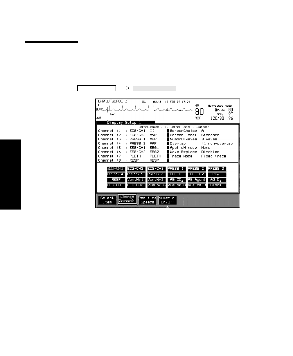
Assigning Waves to Screen Channels
Assigning Waves to Screen Channels
You can assign realtime waves to positions on the screen. This defines
where the waves appear on the Main Screen.
Monitor Setup
Monitor
Setting up your
Notes—
• You can also return to the Display Setup Task Window from the
Realtime Speeds Task Window b y pressing the softkey Display
Setup.
Display1 Setup
3-8 Setting up your Monitor
Page 83

Assigning Waves to Screen Channels
Procedure 1. Press repeatedly to select a channel on the
Select Item
screen.
2. Press to move the selection to the wave you want
Change Content
to place in your selected channel.
3. Repeat steps 1 and 2 for each wave position you want to change.
4. Press to return to the Main Screen screen.
Note—
Main Screen
If one of the assigned waves is not available (parameter switched
off or unplugged), then another wave will use its channel until the
assigned wave is reactivated, provided Wave Replace Mode is enabled.
The channel will only remain blank if:
• It is assigned to ECG or Blank.
• Another wave is available, but numerics aligned to that wave are
switched off.
Monitor
Setting up your
Setting up your Monitor
3-9
Page 84
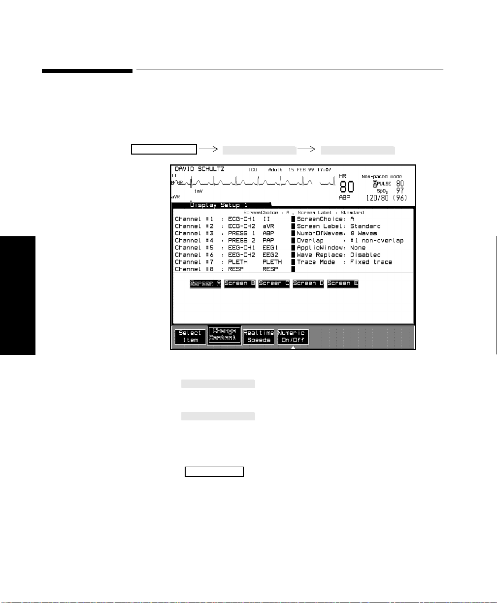
Selecting a Screen
Selecting a Screen
Monitor
You can switch between the five available screens (A-E) in the Display
Setup Task window.
Display1 Setup Select Item
Monitor Setup
Setting up your
Procedure 1. Press until “Screen Choice” is selected on the
screen.
2. Press to select a screen (A-E). The selected
screen choice and its screen label will appear at the top of the
Task Window. The other items on the screen will change
depending on the conf iguration of the different screens
3. Press to return to the Main Screen.
3-10 Setting up your Monitor
Select Item
Change Content
Main Screen
Page 85

Selecting Screen Labels for Realtime Display Screens
Selecting Screen Labels for Realtime Display Screens
A screen label may be selected for a realtime display screen. There are
eleven choices.
Monitor Setup
Procedure 1. Press until “Screen Label” is selected on the
screen.
2. Press to select the key label that you require. The
choices are:
a. Neuro
b. Cardvasc
c. SwanGanz
d. Standard
e. Ventilat
f. Perfusn
g. Surgeon
Select Item
Change Content
Display1 Setup Select Item
Monitor
Setting up your
Setting up your Monitor
3-11
Page 86

Selecting Screen Labels for Realtime Display Screens
Confirm
Confirm
h. Inductn
i. Non Invasive
j. OxyCRG3.
k. Blank (No screen label).
l. User Def (user defined screen label - see below)
User Defined
Screen Labels
3. Press to return to the Selection Window or press
In addition to the pre- defined screen labels, you can define your own
labels for each screen (A-E). To define a screen la bel:
Monitor Setup
Main Screen
to return to the Main Screen screen.
1. Select User Def in the Displa y Setup Task Window.
2. Press .
3. Enter new label using either the handheld keypad, the touchboard
(CMS only) or the arrow keys (V24/26).
4. Press .
Monitor
5. The user defined l abels will also ap pe ar i n th e C ha ng e S cr ee n Task
Window
Setting up your
3-12 Setting up your Monitor
Page 87
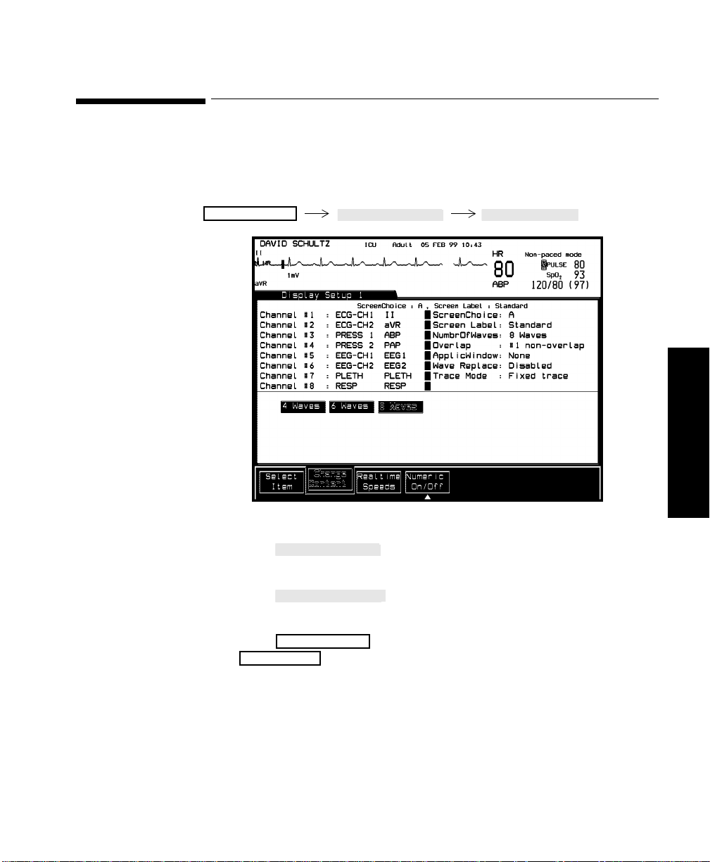
Selecting the Number of Waves
Main Screen
You can select how many waves you want displayed on the screen (within
the capabilities of the model you have ordered).
Selecting the Number of Waves
Monitor Setup
Procedure 1. Press until “NumbrOfWaves” is selected on the
Select Item
Display1 Setup Select Item
screen.
2. Press
Change Content
to choose 4, 6, or 8 waves to be displayed
depending on your mode l.
Monitor
Setting up your
3. Press to return to the Selection Window or
Monitor Setup
to return to the main screen.
Setting up your Monitor
3-13
Page 88

Changing the Wave Overlap
Changing the Wave Overlap
The wave overlap refers to the position of particular waves on the
screen. You can select to have overlapping and non-overlapping waves.
Overlapping waves allow a larger wave amplitude and you can compare
waveforms of various parameters (i.e. pressure waves).
Monitor Setup
Monitor
Display1 Setup Select Item
Setting up your
Procedure 1. Press until “Overlap” is selected on the screen.
2. Press to choose one of the available numbers
Select Item
Change Content
(dependent on mode l). The boxes in the middle of the screen
indicate which waves are overlapping.
3. Press to return to the Selection Window or
Monitor Setup
Main Screen
to return to the Main Screen.
3-14 Setting up your Monitor
Page 89

Selecting Real t im e Wave Speed s
The same speed can be select ed for all the waveforms or dif ferent speeds
can be chosen for different waveforms. You can select the speed for the
waveforms from the following:
50 mm/sec
25 mm/sec
12.5 mm/sec
6.25 mm/sec
Selecting Realtime Wave Speeds
Monitor Setup
Display1 Setup Realtime Speeds
Procedure To select different speeds for the waveforms:
1. Press the softkey repeatedly to select a
parameter to which you want to assign a different speed.
Select Parameter
Monitor
Setting up your
2. Press repeatedly to select the speed you require.
Select Speed
Setting up your Monitor
3-15
Page 90

Selecting Realtime Wave Speeds
3. Repeat steps 1 and 2 for each parameter speed you want to
change.
Press the softkey to return to the Realtime Waves
Task Window, press to return to the Selection Window
or to return to the Main Screen.
Main Screen
Display Setup
Monitor Setup
To select the sa me speed for all th e waveforms:
1. Press
Global Speed
2. Press the softkey to return to the Realtime
Waves Task Window, press to return to the
Selection window or to return to the Main Sc reen.
Note—
repeatedly to select the speed you require.
Display Setup
Monitor Setup
Main Screen
• The speed of the Resp or CO2 waves and of the AG waves must
always be set individually . You cannot alter their speeds by
pressing .
Monitor
Setting up your
• If waves ov erlap, all the wav es travel at the speed of the wa ve in
the first overlapping channel. If the overlap is then changed to
Global Speed
non-overlapping waves each wave travels at its assigned speed.
3-16 Setting up your Monitor
Page 91

Selecting Realtime Wave Speeds
Numerics
On/Off
To tailor the numeric display format to specific needs, individual
numerics can be switched on or off. This is possible for each individua l
screen (A-E) of an independent display. When monitoring many
parameters, switching off the numerics for some of the parameters results
in more of the remaining numerics being displayed in la rge digits.
Monitor Setup
Display1 Setup Numerics1 On/Off
Monitor
Setting up your
1. Press the softkey to highlight the required
parameter numeric. To vi ew parameters which are not displayed,
press the softkey
2. Press the softkey to set the selected numeric
display on or off.
3. Repeat Steps 1 and 2 for each numeric that requires resetting.
4. Press the softkey
off at the same time.
5. Press to return to the Main Screen.
Main Screen
Select Numeric
Next Page
On/Off Numeric
All Num On/Off
.
to switch ALL numerics on or
Setting up your Monitor
3-17
Page 92

Selecting Realtime Wave Speeds
If numerics are switched off, the status message
displayed”
is displayed. This message can be disabled in
“Not all numerics
configuration mode by your biomedical engineer or by the Agi l ent
service engineer.
Numeric
Positioning
Parameter numerics on the Main Screen screen are shown as aligned
numerics - the numerics are next to the corresponding waveforms.
Aligned Numerics:
The monitor controls the position of numerics on the screen, and also
controls the size of some numeric s .
Numeric Positions:
Numerics are positioned on the screen in the follow ing order:
1. Parameters wit h waveforms (such as Pressure) are positioned
first. The numerics are aligned with the corresponding waveform.
2. Numerics, which are part of a contiguous block (i.e. CO2, AG M,
ST, BIS, HR/PULSE) are positioned ne xt .
Monitor
Setting up your
3. Parameters without wa veforms which are not part of a contiguous
block (such as Temperature) are positioned in the left column if
space is available. Otherwise, they are placed from bottom to top
in a column to the right of the waveform numerics according to
their priority as shown in the Numerics On/Off Task Window.
3-18 Setting up your Monitor
Page 93

Selecting Realtime Wave Speeds
Numeric Sizes:
Parameter numerics on the screen are displayed in 2 sizes - big or small.
When there are too many large numerics to be displayed on the Main
Screen display, the monit or performs the following actions to make more
space available:
• The large numerics decreas e in size, starting from bottom to top .
• If more than o ne temperature is being mo nitored, the additional
temperatures are shown continuously in rotation in the position of
the third temperature numeric
Invasive pressures are multi-numeric parameters because each
pressure has numerics for systolic, diastolic and mean pressures.
They are decreased in size. Pressure 1 (P1 ) numer ics prefer ably stay
big.
Additional
Information
• The ST1, ST2, and ST3 values are shown next to the 2nd ECG
channel if present.
• The NBP numerics are displayed big next to the 2nd or 3r d ECG
channels or a blank channel.
• CO2, AGM, and BIS n ume ri cs ar e each preferably k ep t to gether as a
block.
Monitor
Setting up your
Setting up your Monitor
3-19
Page 94
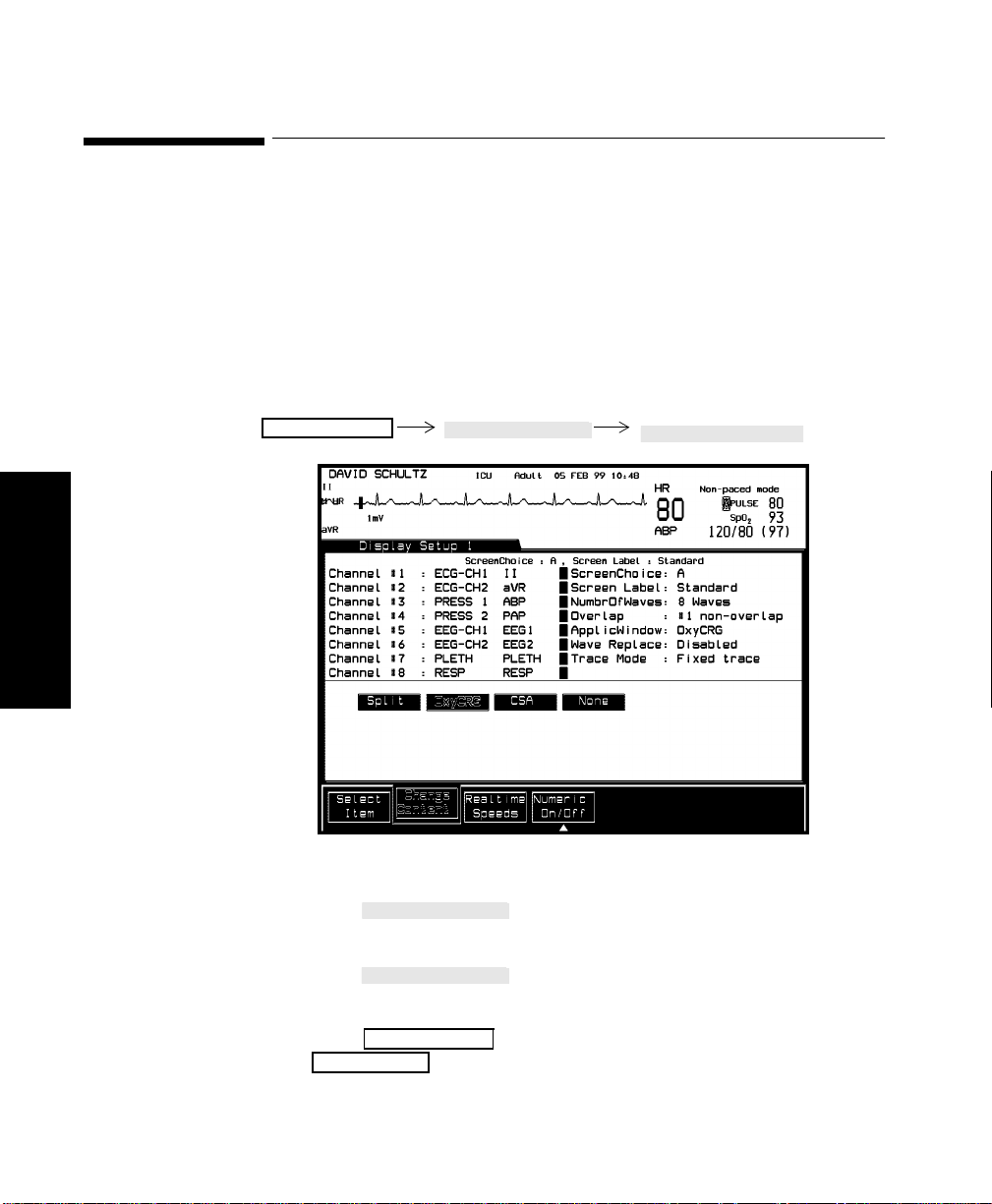
Selecting an Application Window
Selecting an Application Window
One of three application windows can be selected for display in each
screen:
• Split Screen
• oxyCRG
•CSA
They are described in more detai l in t he following sections.
Monitor Setup
Monitor
Display1 Setup
Select Item
Setting up your
Procedure 1. Press until “ApplicWindow” is se lected on the
Select Item
screen.
2. Press to choose Split, OxyCRG, CSA or None (no
Change Content
application window) t o be displayed.
3. Press to return to the selection wi ndow or
Monitor Setup
Main Screen
to return to the Main Screen.
3-20 Setting up your Monitor
Page 95

Selecting an Application Wind ow
Note—
If you have configured a second or third independent display,
oxyCRG and CSA can only be on one of the s e displays at a time. Split
Screen can be configured for all displays simultaneously.
Special Implications for Touch or Mouse Operation
• If Split Screen is active and a split trend is selected, the Graph
Trends Window opens up displaying the selected parameter in
combination with the a djacent parameters.
• If the oxyCRG display is active and is selected, the Neonatal Event
Review Window opens up. If Neonatal Event Review is not
available, the Graph Trends Task Windoe opens up.
• If the CSA Display is active and is selected , the EEG Setup Window
opens up
Monitor
Setting up your Monitor
Setting up your
3-21
Page 96
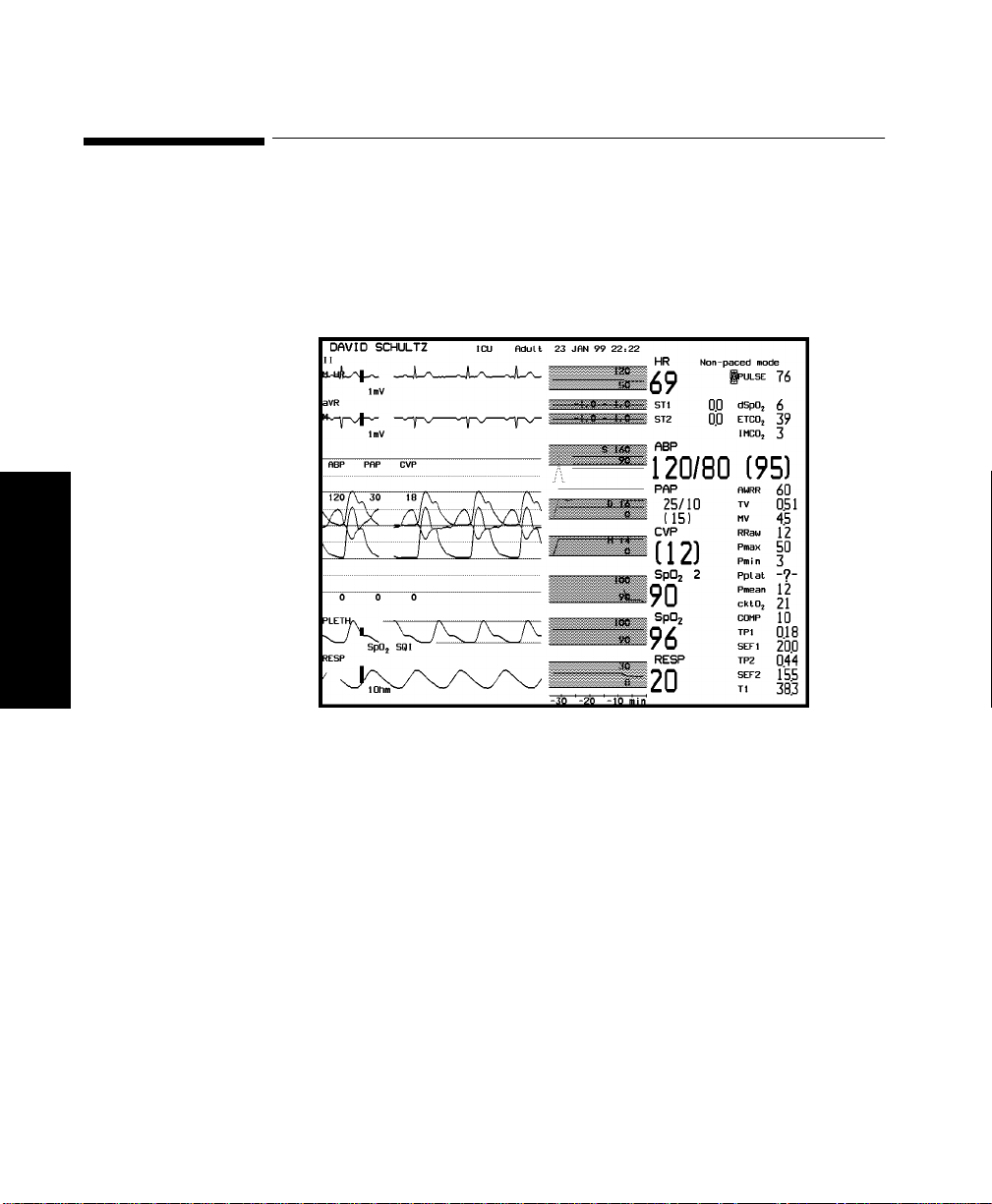
Displaying Split Screen Trends
Displaying Split Screen Trends
Split Screen trends display the last 30 minutes of the patient’s trend data
along with any alarm limits that are set. The trend values are updated
every minute. The tr end va l ue itsel f is calculated as th e a ver ag e of all the
values sampled with th e pre vi o us min ute.
Monitor
Setting up your
3-22 Setting up your Monitor
With Split Screen tren ding you can:
• Display the preceding 30 minutes of trend data for all vital signs
next to their waves.
• Obtain a clear indication if a patient's vital signs tend towards
exceeding the alarm limits.
Note—
Split Screen Trends are not avai lable with selected Agilent V24
and V26 ICU bundles.
Page 97

Displaying S plit Screen Trends
The alarm limits are represented by a rectangle, filled with the
parameter’s color at low intensity. When a measurement exceeds an
alarm limit, it is clea rly visible against the screen’s black background. The
limits themselves are displayed on the right side of the trend display, next
to their corresponding boundaries.
The alarm-limit values are always displayed within the rectangle defined
by alarm limits, if they fit.
Note—
Some trends, such as vital signs that are received through VueLink,
do not have alarm limits associated with them. In this case, no rectangle
is displayed for the alarm range. Instead, the default range scales are
displayed with low intensity on th e left side of the trend display, to
distinguish them from alarm limits.
Trend data is only displayed for those vital signs that are positioned in the
left column of the numeric display.
Viewing Trend
Data for
Invasive Blood
Pressure
Three trend values are displayed for invasive pressure; systolic, diastolic,
and mean pressure. These three trend s are displ ayed together as sho wn in
the diagram below.
Monitor
Setting up your
Display of Trend Data for Invasive Blood Pressure - Example
The alarm limits can apply to any of the three pressures, depending on
how they are configured. The alarm limits are therefore prefixed with a
letter, which identifies the pressure to which they are configured. These
letters are:
S Systolic pressure
D Diastolic pressure
M Mean pressure
Setting up your Monitor
3-23
Page 98

Displaying Split Screen Trends
In addition to this, the trend to which the alarm limits apply is displayed
with a thicker line than the other trends.
Viewing Trend
Data for Non-
invasive Blood
Because the NBP is not a continuously measured parameter, a special
symbol is used to display the trend va lues, as shown in the diagram
below.
Pressure
Display of Trend Data for Non-invasive Blood Pressure - Example
Monitor
Setting up your
3-24 Setting up your Monitor
Page 99

oxyCRG Display
The oxyCRG (oxygen CardioRespiroGram) display provides a
simultaneous presentation of the following three waveforms overlayed on
the Main Screen:
• Beat-to-beat heartrate trend
• An oxygen parameter trend
• Compressed respiration wav e
Approximately the last six minutes of informatio n is displayed for each
parameter.
oxyCRG Display
Monitor
Main Screen Display with oxyCRG
The oxyCRG display can help you to make early detections of respiratory
regulation problems in neonates, by comparing trend patterns, or finding
interrelationships among the three parameters.
Setting up your Monitor
3-25
Setting up your
Page 100

oxyCRG Display
Approximately the bo ttom two thirds of the Main Screen area are
covered with the three oxyCRG waveforms.
The number of realtime waves that you can display simultaneously with
oxyCRG is related to the maximum number of realti me waves that your
system is capable of displaying. Details are provided in the following
table:
Main Screen
Standard Display oxyCRG Display
4 realtime waves oxyCRG + 1 realtime wave
6 realtime waves oxyCRG + 2 realtime waves
8 realtime waves oxyCRG + 3 realtime waves
Monitor
Setting up your
Notes on
oxyCRG
• The oxyCRG informatio n i s ov er la yed on the realtime waves at the
bottom of the Main Screen. These realtime waves disappear from
the display, but the parameters are still being monitored, and the
parameter alarms ar e still active.
• If oxyCRG covers part of an overlap channel, the entire overlap
channel disappears from the display.
•The
• The beat-to-beat heart rate (btbHR) in the oxyCRG display will
• If the monitor is switched off for less than 60 seconds, oxyCRG
Freeze Waves
of the Main Screen, because the display speed is very low.
vary from the heart rate (HR) numeric on the Main Screen, since
the HR numeric is an averaged value.
data is retained. However, when the power is switched back on,
you will see gaps in the oxyCRG display. The gaps correspond to
the amount of time it takes the monitor to get the first readings
after power is restored, not the amount of time that the monitor
was switched off. For this reason, yo u cannot properly measure
the time difference between an event which occurs before power
softkey has no effect on the oxyCRG section
3-26 Setting up your Monitor
 Loading...