


Advisor Mainframe
Features
System Guide
Agilent Technologies

Notices
Copyright © 2001, 2002 Agilent
Technologies, Inc. All rights reserved.
No part of this manual may be repr oduced in
any form or by any means (including
electronic storage and retrieval or
translation into a foreign language) without
prior agreement and wri t ten consent fr o m
Agilent Technologies, Inc. as governed by
United States and international copyright
laws.
Manual Part Number
5971-5001
Edition
Third edition, February 2002
Software version 14.0.0
Printed in Singapore
Agilent Technologies, Inc.
5070 Centennial Boulevard
Colorado Springs, CO 80919-2497 USA
Trademarks
Microsoft ® is a U.S. registered trademark
of Microsoft Corporation.
Windows ® and MS Windows ® are U.S.
registered trademarks of Microsoft
Corporation.
Documentation Warranty
The material contained in this document is
subject to change without notice. Agile nt
T echnologies makes no warranty of any kind
with regard to this material, including, but
not limited to, the implied warranties of
merchantability and fitness for a particular
purpose. Agilent Technologies shall not be
liable for errors contained herein or for
incidental or consequential damages in
connection with the furnishing,
performance, or use of this material.
Warranty
A copy of the speci f i c wa r ra n ty terms
applicable to your product and replacement
parts can be obtained from your local Sales
and Service Office.
Technology Licenses
The hardware and/or so ftware described in
this document are furnished under a license
and may be used or copied only in
accordance with the terms of such license.
Product Support
Call your local Agilent Technologie s
representative, or:
Tel: 1-800-452-4844
Fax: 303-754-4802
or call your local Agilent Sales and Service
Office.
Web:
http://onenetworks.comms.agilent.com/
CAUTION
A CAUTION notice denotes a
hazard. It calls attention to an
operating procedure, practice, or
the like that, if not correctly
performed or adhered to, could
result in damage to the product or
loss of important data. Do not
proceed beyo nd a CAUTION notice
until the indicated conditions are
fully understood and met.
WARNING
A WARNING notice denotes a
hazard. It calls attention to an
operating procedure, practic e, or
the like that, if not correctly
performed or adhered to, could
result in pe rsonal injury or death.
Do not proceed beyond a
WARNING notice until the
indicated conditions are fully
understood and met.
2 Advisor Mainf rame Features System Gui de

Certification
Agilent Technologies certifies that this
product met its published specifications at
the time of shipment from the factory.
Agilent Technologies further c ertifies that
its calibration measurement s are t ra c ea b le
to the United States National In s titute of
Standards a nd Tec hnology (for merly
National Bureau of Standards), to the extent
allowed by that organization’s calibration
facility, and to the calibration facilities of
other International Standards Organization
members.
Restricted Rights Legend
If Software i s for use in the per formance of
a U.S. Government prime contract or
subcontract, Software is deli v er e d and
licensed as ìCommercial computer
softwareî as defined in DFAR 252.227-7014
(June 1995), or as a ìcommercial itemî as
defined in FAR 2.101(a) or as ìRestricted
computer s o ftwareî as defined in FAR
52.227-19 (June 1987) or any equivalent
agency regulation or contract clause. Use,
duplication or disclosure of Software is
subject to Agilent Technologiesí standard
commercial license terms, and non-DOD
Departments and Agencies of the U.S.
Government will receive no greater than
Restricted Rights as defined in FAR
52.227-19(c)(1-2) (June 1987). U.S.
Government users will receive no greater
than Limited Rights as defin ed in FAR
52.227-14 (June 1987) or DFAR
252.227-7015 (b)(2) (November 1995), as
applicable in any technical data.
Before you use this instrument, read the
"General Safety Precautions" and
"Additional Safety Information" sections.
Failure to comply with the precautions or
with specific warnings in this book violates
safety standards of design, manufacture,
and intended use of this instrument. Agilent
Technologies assumes no liability for the
customer's failure to comply with these
requirements.
General Safety Precautions
The following warnings and operating
information are shown in English followed
by the French translation.
WARNING
instrument with a protective ear th term in al.
WARNING
shock hazard, power cord ground must not
be defeated .
This product is a Safety Class I
For protection from electric
Operating Restriction s
The following general safety precautions
must be observed during all phases of
operation, service, and repair of this
instrument. Failure to comply with these
precautions with specific warnings in this
manual violate safety standards of design,
manufacture, and intended use of this
instrument.
Grounding
To minimize shock hazard, the instr umen t
chassis and cabinet must be connected to
an electrical ground. The instrument is
equipped with a three-conduc tor AC power
cable compatible with an approved
three-contact electrical outlet. The power
jack and mating plug of the power cord
must meet International Electrotechnical
Commission (IEC) safety standards.
Environment
Do not operate the instrumen t in th e
presence of flammable gases or fumes.
Operation of any electrical instrument in
such an environment constitutes a definite
safety hazard.
Service and Adjustment
Dangerous voltages exist within this
instrument. Service and adjustment of this
instrument is to be perform ed only by
trained service personnel.
Do not replace components with the power
cable connected. Dangerous voltag es may
be present even when t h e p ower cable is
disconnected.
Do not perform internal servicing or
adjustment unless another person, capable
of rendering first aid and resuscitation is
present.
Hazardous Material
Should the LCD be damaged the li quid
crystal material can leak. Avoid all contact
with this material, especially swallowing.
Use soap and water to thoroughly wash all
skin and clothing contaminated with the
liquid crystal material.
Unauthorized Service
The installation of substitute parts or the
installation of any instrument modification
not authorized by Agilent Technolo gies is
specifically forbidden. The performance of
such unauthorized service can negate the
instrument warranty or any maintenance
agreements.
Return the instrument to an Agilent Sales
and Service Office for authorized service
and repair.
MISE ENGARDE
normes de la «Classe de sécurité I» et est
muni d'un fil de mise à la terre pour votre
protection.
MISE ENGARDE
de choc électrique, la broche de mise à la
terre du cordon d'alimentation ne doit pas
être désactivée.
Cet appareil répond aux
Pour prévenir les risques
Restrictions d’utilisation
L'utilisateur se doit d'observer les mesures
de précaution énumérées ci-dessous pour
toutes les phases d'utilisation, de service et
de réparation de cet appareil. Le fait de ne
pas s'y conformer équivaut à ne pas
respecter les mises en gardes spécifiques
contenues dans ce manuel et constitue une
Advisor Mainframe Features System Guide 3
violation des normes de sécurité relatives à
la conception, la fabrication et l'utilisation
prévue de cet appareil. La société Agilent
n'assume aucune responsabilité envers un
client qui manquerait de se conformer à ces
exigences.
Mise à la terre
Afin de minimiser les risques de choc
électrique, le chÀssis et le cabinet de
l'appareil doivent être mis à la terre.
L'appareil est équipé d'un cordon
d'alimentation muni d'une fiche
homoloquée à trois lames, compatible c.a.
La prise murale et la prise femelle de la
rallonge électrique doivent respecter les
normes de sécurité de la «Commision
électrotechnique internationale» (IEC).
Environnement
Ne faites pas fonctionner cet appa r e i l en
présence de gaz inflammables ou de
vapeurs dangereuses. L'utilisation de
n'importe quel appareil électrique dans ces
conditions constitue un risque élevé pour
votre sécurité.
Service et ajusteme nt
Des «tensions dangereuses» résident dans
cet appareil. Par conséquent, le service et
l'ajustement doivent être effectués
uniquement par une personne qualifiée.
Ne remplacez pas de composantes lors qu e
le cordon d'alimentation est sous tension. Il
pourrait y avoir présence de «tensions
dangereuses» même lorsque l'appareil est
déconnecté.
Ne faites pas de service inte r n e ou
d'ajustement sauf en présence d'une autre
personne, capabl e de prodiguer les premie rs
soins et de pratiquer la réanimation.
Matière dangereuse
Si l'affichag e LC D es t en dommagé, la
matière constituant les cristaux liquides
peut se répandre. Eviter tout contact avec
cette matière, et en particulier ne pas
l'avaler. Utiliser de l'eau et du savon pour
nettoyer soigneusemen t la peau et les
vêtements qui auraient été contaminés par
la matière constituant les cristaux liquides.
Service non autorisé
L'installation de pièces étrangères, ou toute
modification apportée à l'appareil sans le
consentement de Agilent est formellement
interdit. Le fait de procéder à de tels
modifications sans autorisation pourrait
entraîner l'annulation de la garantie de
l'appareil ou de tout contrat de service.
Pour un service et des réparations
autorisées, retournez l'appareil à un point
de vente et service Agilent.
Additional Safety Information
Electric Shock Hazard
Do not remove the system covers. To avoid
electric shock, use only the supplied power
cords and connect only to properly
grounded (3-pin) wall outlets.
Explosion Hazard
Do not operate in the presence of
flammable gases.
Fire Hazard
For continued protection against fire hazard
replace only with fuse of same type and
rating.
Cleaning
To clean the product, use a damp cloth
moistened with a mild solution of soap and
water. Do not use harsh chemicals. Do not
let water get into the product.
Product Damage
Do not use this product when the product
shows visible damage, fai l s t o perform, has
been stored in unfavorable conditions, or
has been subject to severe transport
stresses.
Whenever this product has become
damaged or wet, make th e product
inoperative and secure it against any
unintended operation. Contact your nearest
Agilent Sales office for assistance.
Instruction book symbol - the product will
be marked with this symbol when it is
necessary for the user to refer to the
instruction book in order to protect against
damage.
A product marked with this symbol
indicates it is a laser product. When
necessary, this symbol will be included in
the instruction book for the user to refer to
in order to protect against personal injury
and/or correct product handl in g.
Indicates potentia l for electrical shock.
This is an Installation Category II product.
This is a Pollution Degree 2 product.
This product is designed for indoor use only.
FCC Part 68 Disclaimer
This equipment must not be connected to
the telephone network unless it is
connected through protective circuitry that
is registered pursuant to Part 68 of the
Federal Communications Commission rules.
4 Advisor Mainf rame Features System Gui de

ATTENTION. USE OF THE SOFTWARE IS SUBJECT TO THE AGILENT TECHNOLOGIES SOFTWARE LICENSE TERMS SET FORTH
BELOW. USING THE SOFTWARE INDICATES YOUR ACCEPTANCE OF THESE LICENSE TERMS. IF YOU DO NOT ACCEP T TH ESE
LICENSE TERMS, YOU MAY RETURN THE SOFTWARE FOR A FULL REFUND. IF THE SOFTWARE IS BUNDLED WITH AN O TH ER
PRODUCT, YOU MAY RETURN THE ENTIRE UNUSED PRODUCT FO R A FULL REFUND.
AGILENT TECHNOLOGIES SOFTWARE LICENSE TERMS
The following License Terms gove rn your use of the accompanying Softw are unless you have a separate signed agreement with
Agilent Technologies.
License Grant. Agilent Technologies grants you a license to Use one copy of the Software. "Use" means storing, loading, installing,
executing or displaying the Software. You may not modify the Software or disable any licensing or control features of the Software. If
the Software is licensed for "concurrent use", you may not allow m ore than the m a ximum number of authorized users to Use the
Software concurrently.
Ownership. The Software is owned and copyrighted by Agilent Technologies or its third party suppliers. Your license confers no title
to, or ownership in, the Software and is not a sale of any rights in the Software. Agilent Te chnolog ies’s third party suppliers m ay
protect their rights in the event of any violation of these License Terms.
Copies and Adaptations. You may only make copies or adaptations of the Software for archival purposes or when copying or
adaptation is an essential step in the authorized Use of the Software. You must reproduce all copyright notices in the original
Software on all copies or adaptations. You may not copy the Software onto any public network.
No Disassembly or Decryption. You may not disassemble or decompile the Software unless Agilent’s prior written consent is
obtained. In some jurisdictions, Agilent’s consent may not be required for limited disassembly or decompilation. Up on req uest, you
will provide Agilent Technolog ies w ith reasonab ly d etailed inform atio n rega rding any disassem bly or decom pilation . You may not
decrypt the Software unless decryption is a necessary part of the operation of the Software.
Transfer. Yo ur license will automatically terminate upon any transfer of the Software. Upon transfer, you must deliver the Software,
including any copies and related documentation, to the transferee. The transferee must accept these License Terms as a condition to
the trans f er.
Termination. Agilent T echnologies may terminate your license upon notice for failure to comply with any of these License Terms.
Upon termination, y o u mu s t i mme di a te l y destroy the Software, together wit h a ll copies, adaptations and merged porti o ns i n any f orm.
Export Requirements. You may not export or re-export the Software or any copy or adaptation in violation of any applicable laws or
regulations.
U.S. Government Restricted Rights. The Software and any accompanying documentation have been dev eloped entirely at private
expense. They are delivered and licensed as "commercial computer software" as defined in DFARS 252.227-7013 (Oct 1988), DFARS
252.211-7015 (May 1991) or DFARS 252.227-7014 (Jun 1995), as a "commercial item" as defined in FAR 2.101(a), or as "Restricted
computer software" as defined in FAR 52.227-19 (Jun 1987)(or any equivalent agency regulation or contract clause), whichever is
applicable. Yo u have only those rights provided for such Software and any accompanying documentation by the applicable FAR or
DFARS clause or the Agilent standard sof twa re agreement for the product invo lved .
Microsoft Products. Microsoft Products are licensed to you under the Micr osof t End Us er Lic ense Agreement (EULA) contained in
the Microsoft documentation. Microsoft Products are covered under the Agilent Technologies warranty Statement supplied with the
Agilent Products. The warranties in the Microsoft Documentation will not apply.
Advisor Mainframe Features System Guide 5

In This Manual
This manual provides information about the Advisor
system hardware and software. Refer to the
technology-specific Getting Started Guides for
information relating to LAN, WAN, or ATM testing. Refer
to the Operating System Guide for more information.
1 Mainframe Overview
This chapter provides overview information about the
Advisor and available Interface Modules or Undercradles.
2 Getting Started
This chapter explains how to start using the Agilent
Advisor. Information such as powering on the Advisor,
starting measurements, and connecting peripheral
devices to the Advisor are covered.
3 Installing/Removing Interface Modules
This chapter explains how to install and remove several
different Interface Modules and Filler Panels available for
use with the Advisor.
4 Attaching/Removing Undecradles
This chapter explains how to attach and remove
undercradles that are used with the Advisor.
5 Recovering/Re-installing Software
This chapter has information about installing Windows
from your hard drive, installing or upgrading the Advisor
software, and viewing electronic documentation.
6 Using Modem & Ethernet PC Cards
This chapter explains how PC Card slots are used with the
Advisor to increase the flexibility in the Personal
6 Advisor Mainf rame Features System Gui de

Computer section and for enhanced I/O capability with
the Advisor software.
A Specifications
This appendix lists the various specifications for the
Agilent Advisor.
B Breakout Box, LEDs, and Connectors
This appendix gives you specific information about the
Advisor’s Breakout Box, LEDs and Connectors.
C Regulatory Information
This appendix contains all Declarations of Conformity
statements for all hardware components, Laser Safety
statements, and other regulatory information.
Advisor Mainframe Features System Guide 7

8 Advisor Mainf rame Features System Gui de

Contents
Contents
1 Mainframe Overview
Introduction 14
Product Matrix 15
2 Getting Started
Powering on the Advisor 20
Starting the Advisor the First Time 21
Setting the Date and Time 22
Starting an Advisor Application 23
Connecting an External Di splay Monitor 24
Setting VGA Display Mode 25
Connecting a Printer 26
3 Installing/Removing Interface Modules
Installing Interface Modules 28
Removing Interface Modules 29
4 Attaching/Remo vi n g Un dercradles
Tools Requ i r ed 32
Attaching an Undercradle 33
Removing an Undercradle 34
Using the Empty J2 29 5 A Un de r cr a dl e 35
Disassembling th e J2295A Undercradle 35
Installing Printed Circuit Cards 36
Re-assemblin g the J2295A Underc r a dl e 37
5 Recovering/Re-installing Software
Installing Windows 98 From the Hard Drive Image 40
Installing/Upgrading Advisor Software 42
Advisor Mainframe Features System Guide 9

Contents
Viewing Electronic Documentation 42
6 Using Modem & Ethernet PC Cards
Introduction 44
Installing and Removing PC Card s 45
To Install a PC Card 46
To Remove a PC Card 47
Software Configuration 47
PC Card Modems 50
A Specifications
Physical Specifications 52
Operating Conditions 53
J2300D/E Specifications 54
J3446D/E Specification s 56
The Keyboard and B utton Mouse 58
B Breakout Box, LEDs, and Connectors
RS-232/V.24 Breakout Box and System LEDs 62
Mark/Space Indicator 63
Source Voltage 64
Active Interface LE Ds 64
Lead Status LEDs 65
V-Series Interfaces 66
RS-232C/V.24 67
RS-449 68
V.35 69
Interface Pin-Out Comparison 70
AUI — 100Base-T 72
MII — 100Base-T 73
MDI — 100Base-TX 74
10 Advisor Mainf ra me Features System Gui de

C Regulatory Information
Declarations of Confor mity 76
J1990A Full Duplex Ethernet Tap 76
J2294C CEPT-E1 DB9 & RJ-45 Interface Module 77
J2294D, J2296D, J2 298D E1 and T1 Interface Modules 78
J2300D Advisor WAN 79
J2300E Advisor WAN 80
J2306B, J2309B LAN Ethernet and Eth/Token Ring Undercradle 81
J2307A LAN Token Ring Undercradle 82
J2524A FDDI Undercradle 83
J2527A TIMS Under cradle 84
J2900A High Speed Acquisitio n Undercradle 85
J2901A Gigabit Ethernet Undercradle 86
J2904B, J2293B/94B/96B/97B/98B/99B ISDN/BERT Interface
Modules 87
J2905B ISDN BRI S/T an d U I nterface Module 88
J2908A DDS 4-Wire Interface Module 89
J2909A ATM DS-3/E3 Interface Module 90
J2912A ATM OC-3c/STM-1 Interface Module 91
J2912B ATM OC-3c/STM-1 Interface Module 92
J2913A ATM 155-UTP Interface Module 93
J2913B ATM 155-UTP Interface Module 94
J2914A STM-1e Inte rface Module 95
J3444A Fast Ethernet LAN Undercradle 96
J3445A 100Base-FX Interface Module 97
J3446D Advisor LAN 98
J3446E Advisor LAN 99
J3447A LAN 100BaseFX In terface Module 100
J3759A DS-3/E3 Cells & Frames Interface Module 101
J3759B DS-3/E3 Cells & Frames Interface Module 102
J3762A HSSI Interfac e Module 103
J3762B HSSI Interface Module 104
J3763A, J3764A ATM 622 Undercradle and OC-1 2/STM-4c
Interface Module 105
J3766A ATM25 Interface Module 106
J4630A VQT Undercradle 107
J4646A/47A and J4648A/49A E1 and T1 ISDN PRI Interface
Modules 108
Contents
Advisor Mainframe Features System Guide 11

Contents
J5457A High-Speed V-Series Interface Module 109
Laser Safety Statements 110
Safety Information for Laser Source Modules 111
Index
12 Advisor Mainf ra me Features System Gui de

1
Mainframe Overview
Introduction 14
Product Matrix 15
Agilent Technologies
13
1 Mainframe Ove rview
Introduction
The Agilent Advisor models J2300D, J2300E, J3446D, and
J3446E are designed for testing your network needs in
combination with available WAN, LAN, ISDN, and ATM
Interface Modules or Undercradles. With the Advisor, you can
look at decoded protocol information as it is traveling across a
network so you can identify network problems quickly.
This manual provides information about the Advisor system
hardware and software. Refer to the technology-specific Getting
Started Guides for information relating to LAN, WAN, or ATM
testing. Refer to the Operating System Guide for more
information.
Model “D”
Advisors
Model “E”
Advisors
The J2300D and J3446D Advisors have:
• AMD K6-2 chip
• 300 MHz processor
• 128 Mbytes of PC memory
• 1.44 MB flexible disk drive
• 4 GB (or larger) hard drive
The J2300E and J3446E Advisors operate at a higher speed and
have more memory. These Advisors have:
• AMD K6-III w/L2 Cache-256K
• 400 MHz processor
• 256 Mbytes of PC memory
• 1.44 MB flexible disk drive
• 6 GB (or larger) hard drive
Each mainframe has a PC Card Type III slot, serial port, parallel
port, external monitor port, microphone input jack, and an
external audio output jack. The mainframes have available
options of: a TDK 56.6 Kbps Modem PC Card and/or a Xircom
Combination Modem and Network Interface CardBus Card.
There are two speakers in the mainframes for sound output.
Volume control is included in the software. External speakers or
a headset can be plugged into the jack labeled, “PHONES”.
14 Advisor Mainf ra me Features System Gui de

Product Matrix
Mainframe Overview 1
J2300D/J2300E
Undercradles
J2295A X X
J2306A Ethernet LAN X X
J2306B Ethernet LAN X X
J2307A Token Ring LAN X X
J2309A Ethernet/TR L AN X X
J2309B Ethernet/T R LAN X X
J2524A FDDI X X
J2527A TIMS X
J2900A High Speed Acquisition X X
J2901A X X
J3444A Fast Ethernet X X
J3763A X X
E4594A TELCO X
E6323A E1 TELCO X
WAN Mainframes
J3446D/J3446E Fast
Ethernet LAN
Mainframes
X =Supported Now
Advisor Mainframe Features System Guide 15

1 Mainframe Ove rview
J2300D/J2300E Mainframes
or J2900A Undercradle
Interface Modules WAN ATM Application
J4646A/47A ISDN PRI E1 X
J4648A/49A ISDN PRI T1 X
J2293B PRI-E1 X X
J2294B PRI-E1 X X
J2294C PRI-E1 X X
J2294D T1/E1 X X
J2296B PRI-E1 X X
J2296D E1 X X
J2297B PRI-E1 X X
J2298B PRI-T1 X X
J2298D T1/E1 X X
J2299B PRI-T1 X X
J2904B ISDN BRI S/T X
J2905B ISDN BRI S/T & U X
J2908A DDS 4-Wire X
J2909A ATM DS-3
1
X
J2911A ATM J2 X
J2912A ATM OC-3 X
J2912B OC-3 X
J2913A ATM-UTP
1
X
J2913B ATM-UTP X
J3759A ATM DS3/E3 X X
J3759B ATM DS3/E3 X X
J3762A WAN HSSI X
J3762B WAN HSSI X
J3766A ATM 25.6M X
1
Only used in a J2300D or J2300E mainframe.
16 Advisor Mainf ra me Features System Gui de

Interface Module
J3447A 100BaseFX X
Interface Module
Mainframe Overview 1
J3446D/J3446E Fast Ethe rnet
LAN Mainframe
J2300D/J2300E WAN Mainframes
and J3446D/J3446E LAN Mainframes
with J3444A Undercradle
Media Independent
Interface
J3445A Fiber Interface X
X
Advisor Mainframe Features System Guide 17

1 Mainframe Ove rview
18 Advisor Mainf ra me Features System Gui de

2
Getting Started
Powering on the Advisor 20
Starting the Advisor the First Time 21
Setting the Date and Time 22
Starting an Advisor Application 23
Connecting an External Display Monitor 24
Setting VGA Display Mode 25
Connecting a Printer 26
Agilent Technologies
19

2 Getting Started
CAUTION
Powering on the Advisor
Connect the AC power cable (either 115V or 230V) as shown
below. The mainframe automatically determines whether the
power connection is 115V or 230V. To start the mainframe, turn
the power on. The ON-OFF power switch is located on the left
side adjacent to the power cable connector.
ON/OFF Power Switch
(Fuse Holder)
20 Advisor Mainf ra me Features System Gui de
If the mainframe will not power-up, check the following:
• Power cable connections are good
• AC power is available at the outlet
• Examine the fuse
Each mainframe is shipped with a three-conduct or po wer cable that
grounds the Advisor when it is connected to an appropriate power outlet.
Do not operate th e Advisor without ground protection.

Starting the Advisor the First Time
Windows and Advisor software are already installed on the
hard drive at the factory. The software is included with your
shipment for recovery/re-installation only.
When you first power up the Advisor, you will need to enter
some initial Microsoft Windows setup information.
1 Plug in the Advisor and turn it on (the On/Off switch is
located next to the power cord on the left side of the unit).
2 Follow the instructions on the screen to enter a first and last
name, and to accept the Microsoft Windows license
agreement.
3 Enter the Microsoft Windows authenticity product ID#
affixed to the mainframe.
4 When the Date/Time Properties dialog is displayed, set the
date and time, select the time zone, and press Enter.
The time and date features are used for many of the
applications and reports generated by the Advisor. It is
important to set your local time and date when you receive
your Advisor. Setting the time and date also updates system
configuration files. The time and date are maintained even
when the Advisor is off.
5 After the Windows setup is complete, shut down and power
off the unit to update setup files and to prepare the Advisor
for running measurements.
Getting Started 2
Advisor Mainframe Features System Guide 21

2 Getting Started
Setting the Date and Time
.
The time and date features are used for many of the
applications and reports generated by the Advisor. It is
important to set your local time and date when you receive your
Advisor. Setting the time and date also updates system
configuration files. The time and date are maintained even
when power to the Advisor is off
Open the Control Panel.
1
Open the Date/Time Properties
2
window and set the date and
time.
22 Advisor Mainf ra me Features System Gui de

Starting an Advisor Application
All of your applications can be started from Windows desktop.
Depending on the type of mainframe you have and any
undercradles or modules you have installed, the available
applications will be displayed on the Start menu. Refer to the
technology-specific (ATM, WAN, LAN) Getting Started Guides
for specific startup instructions.
Getting Started 2
Advisor Mainframe Features System Guide 23

2 Getting Started
Connecting an External Display Monitor
You can connect an external display monitor to the Advisor.
With an Active SVGA display, the external monitor display is
SVGA resolution 800x600.
If you want to adjust the display to a higher resolution you must
explicitly change the display mode to External Monitor Only.
To connect an External Display Monitor:
1. Turn off the Advisor.
2. Connect the monitor to the EXT
MONITOR port on the mainframe.
3. The External Display Monitor will
automatically be detected when
you turn on the mainframe.
Set the Display
Mode to External
Monitor Only.
24 Advisor Mainf ra me Features System Gui de
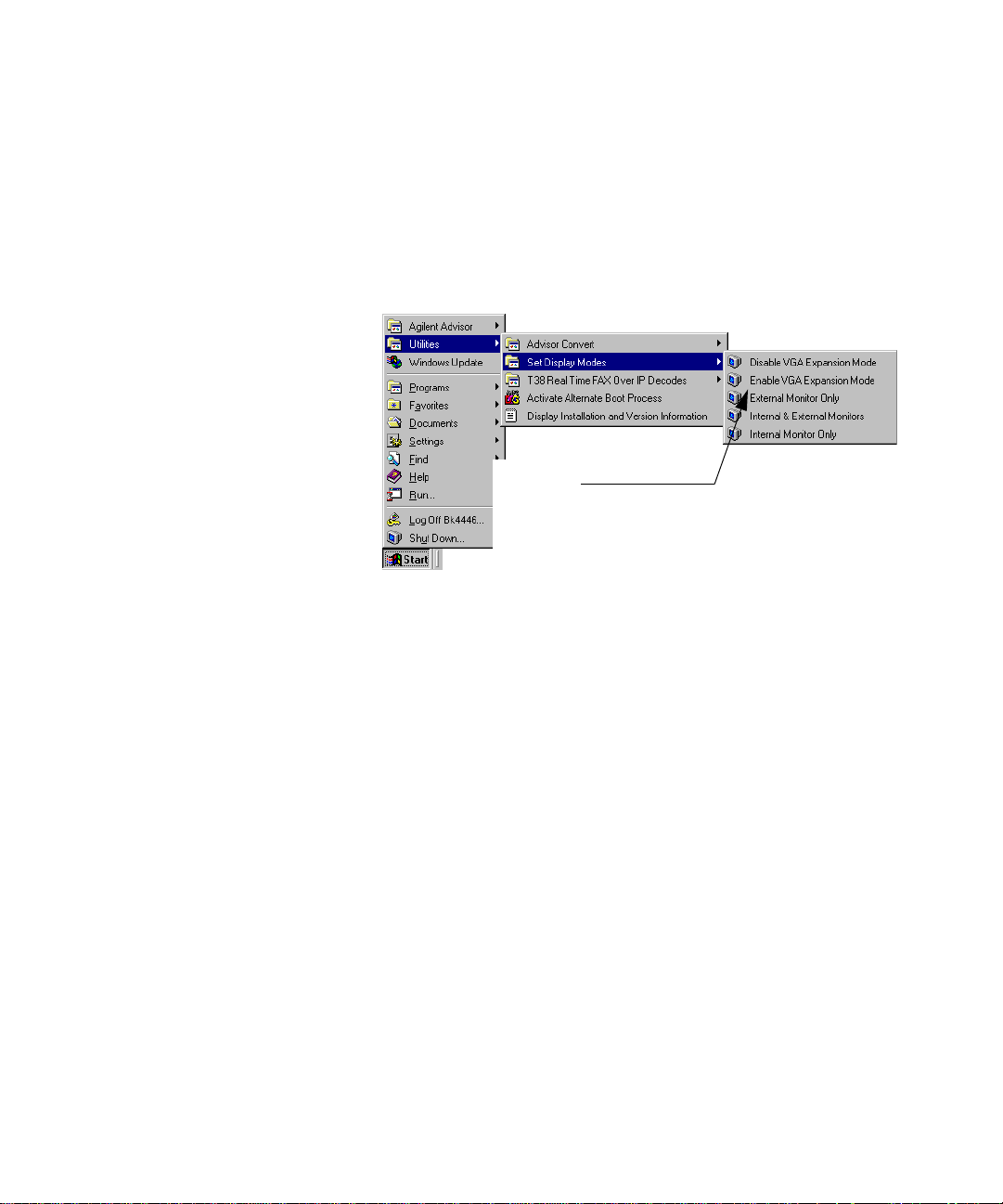
Setting VGA Display Mode
Getting Started 2
You can either disable or enable VGA Expansion Mode under
Utilities on the Start menu.
Disable or enable
VGA Expansion
Mode.
Advisor Mainframe Features System Guide 25

2 Getting Started
Connecting a Printer
You can connect a printer to the Advisor so you can print files,
help topics, and measurements results. The default printer
selection is No Printer. If you want to use a printer with your
Advisor, you must select the printer driver and output port.
Connect a printer to the PARALLEL
1
port on the ma i nframe.
Open the Printers window.
2
Open the Add Printer Wizard and
3
follow the directions on the
screen.
26 Advisor Mainf ra me Features System Gui de

3
Installing/Removing Interface Modules
Installing Interface Modules 28
Removing Interface Modules 29
Agilent Technologies
27

3 Installing/Removing Interface Modules
CAUTION
Installing Interface Modules
There are several Interface Modules and one Filler Panel
available for use with the Advisor. The Filler Panel acts as a
cover for the Interface Module slot when no Interface Module is
installed.
You can install interface modules directly into the mainframe or
into a compatible undercradle. Refer to Chapter 1 for supported
Interface Module configurations with the Advisor and
Undercradles.
Make sure you turn off the power and unplug the Advisor before attaching
or removing undercradles.
1 Make sure the Module Release Latch is in the Install/Remove
Position.
2 Slide the Interface Module or Filler Panel into the opening.
3 Push it firmly into place until it is seated and the Module
Release Latch moves to the Locked Position. The Module
Release Latch does not move when you install a Filler Panel.
You will need to push the Module Release Latch to move the
latch into its locked position.
28 Advisor Mainf ra me Features System Gui de
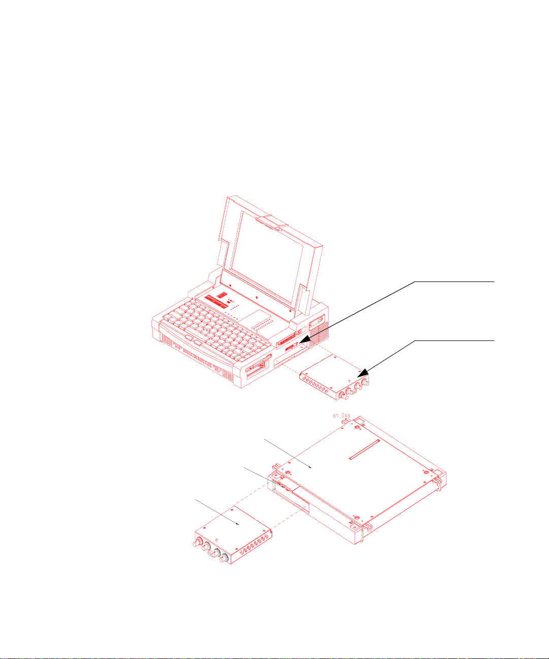
Removing Interface Modules
1 Press the left end of the Module Release Latch (labeled
“PUSH TO UNLOCK”), then slide the latch toward the left
(Install/Remove Position).
2 Pull the Interface Module or Filler Panel out of the Advisor.
Installing/Removing Inter fa ce Modul es 3
Module Release Latch
Interface Module
Undercradle
Module Release Latch
Interface Module
Advisor Mainframe Features System Guide 29

3 Installing/Removing Interface Modules
30 Advisor Mainf ra me Features System Gui de

4
Attaching/Removing Undercradles
Tools Required 32
Attaching an Undercradle 33
Removing an Undercradle 34
Using the Empty J2295A Undercradle 35
Agilent Technologies
31

4 Attaching/Removing Undercradles
NOTE
Tools Required
'HSHQGLQJRQZKLFKXQGHUFUDGOH\RXKDYHRUGHUHG WKHIROORZLQJ
HTXLSPHQWWRROVDUHLQFOXGHGWRDWWDFKDQGUHPRYHWKH
XQGHUFUDGOH
• 4 rubber feet
• 4 Torx screws (for the undercradle)
• 2 Torx screws (not needed for J2300D/E and J3446D/E)
• 1 Right side endcap expander
• 1 Torx wrench
• 1 Small flat endcap
• 1 connector board
• 2 Grounding Strips (not needed for J2300D/E and J3446D/E)
Any E4594A Telco Undercradle without the new E4594A Se rial number
label that includes the phrase “INT 15,” must be modified at your nearest
Service Center in order to operate correctly with the J2300D/E and
J3446D/E Advisors.
32 Advisor Mainf ra me Features System Gui de

Attaching an Undercradle
CAUTION
Attaching/Removing Undercr adl es 4
Turn off the power and unplug the Advisor before attaching or removing
undercradles.
1 If the metal plate (on the bottom of the Advisor) is covering
the opening for the Undercradle to attach to, remove the two
screws from the metal plate. Use the wrench provided in the
miscellaneous parts kit (or a T10 Torx screwdriver) to
remove the screws.
2 Slide the metal plate over to the next set of drilled holes in
the metal plate and re-attach it (with the same screws you
removed in the previous step). This will leave an opening into
which you can install your connector board. Ensure that the
screws are flush with the metal plate.
Advisor Mainframe Features System Guide 33
Screws
Metal Plate

4 Attaching/Removing Undercradles
3 Insert the connector board into the slot uncovered by the
4 Make sure all four silver tabs on the top of the undercradle
5 Place the mainframe on top of the undercradle, matching the
6 Push in the four silver tabs, locking the undercradle to the
metal plate.
are pulled out.
connector on the bottom of the mainframe to the connector
on the top of the undercradle.
mainframe.
Silver Tabs
Removing an Undercradle
1 Turn off the power and unplug the Advisor.
2 Pull out the four silver tabs on the front and the back of the
undercradle.
3 Lift the Advisor away from the undercradle.
34 Advisor Mainf ra me Features System Gui de

Using the Empty J2295A Undercradle
CAUTION
The empty Undercradle (J2295A) can be used with the Advisor
so you can add one or two of your own ISA compatible printed
circuit cards to customize your Advisor.
Disassembling the J2295A Undercradle
Turn off the power and unplug the Advisor before attaching or removing
undercradles.
1 If already attached, remove the undercradle from the
Advisor. Refer to “Removing an Undercradle” on page 34.
2 Turn the undercradle upside down, with the four black feet
facing up.
3 Carefully remove the four black rubber feet using a small flat
screwdriver to pull them out of their seating.
4 Remove the four screws using a #10 Torx driver.
5 Turn the undercradle over.
6 Remove the eight screws (four flat-head and four pan-head)
from the top of the undercradle.
7 Slide the two plastic endcaps off both sides, and lift off the
top of the undercradle.
Attaching/Removing Undercr adl es 4
Advisor Mainframe Features System Guide 35

4 Attaching/Removing Undercradles
CAUTION
Installing Printed Circuit Cards
You can install up to two printed circuit cards in the
undercradle — full-length or smaller. For full-length cards, you
will need to use the endcap expander. For smaller cards or only
one card, you can use the flat endcap.
Be sure to follow Electro-Static Discharge (ESD) procedures when
handling any cards.
1 Gently lift each corner of the connector board to disconnect
2 Turn the connector board over and fasten the card(s) in the
3 Press the connector board onto the standoffs. The cards
4 Included with your undercradle are seven foam blocks. You
5 Remove the protector sheet and place the foam block where
it from the standoffs.
slots provided.
should be underneath the connector board as you secure it.
can use them to help stabilize your PC Cards inside the
undercradle.
needed. It should adhere to the sheet metal and prevent
movement of the cards.
36 Advisor Mainf ra me Features System Gui de

Re-assembling the J2295A Undercradle
1 Place the top back on the undercradle, aligning the slot in the
top with the Advisor connector. Fasten with the four
flat-head screws.
2 On the side nearest to the Advisor connector, slide the left
side piece into place and secure it with four pan-head screws
(two on the top and two on the bottom). If you are only
installing one printed circuit card, insert the small flat
endcap in the left side piece before you put it on the
undercradle.
3 If you are installing full-length printed circuit cards, insert
the endcap expander into the right side before you place it on
the undercradle. If you are installing smaller printed circuit
cards, insert the flat metal endcap in the right side before
you place it on the undercradle.
4 Slide the undercradle right side piece into place and secure it
with four pan-head screws (two on the top and two on the
bottom).
5 Turn the undercradle over and replace the four black rubber
feet into the foot indentations.
Attaching/Removing Undercr adl es 4
Advisor Mainframe Features System Guide 37

4 Attaching/Removing Undercradles
38 Advisor Mainf ra me Features System Gui de

5
Recovering/Re-installing Software
Installing Windows 98 From the Hard Drive Image 40
Installing/Upgrading Advisor Software 42
Viewing Electronic Documentation 42
Agilent Technologies
39

5 Recovering/Re-installing Software
NOTE
Installing Windows 98 From the Hard Drive Image
The Windows 98 operating system image is included on a
separate partition on the hard drive for recovery. It is
recommended you back up this image to a network server or a
CD so you can easily recover the operating system in the event
of a hard drive failure.
Note, the image on this hard drive is not compatible with the
following D series mainframes:
J2300D serial numbers below US41030101
J3446D serial numbers below US41040101
If you have older D series mainframes, you need to keep the
backup images you made for those mainframes. Use this manual
for instructions to install the operating system from the hard
drive image.
When you install Windows 98 Second Edition, you will be
reformatting the C: drive. You will lose all installed applications,
customized tests, and any data files that you have created.
Make sure that you back up ALL files you want to save before you
continue. This process does not install the Advisor software.
System
Requirements t o
install Windows
98 SE
FAT32 support The external hard drives, used for Option 506, do not support
40 Advisor Mainf ra me Features System Gui de
• A D-model Advisor with a 2 GB or larger hard disk
• Backup media archived on a separate partition, as
configured from the factory. Each Advisor shipped from the
factory has two partitions in the hard drive. The second
partition contains the Windows recovery image.
FAT32. If you use FAT32 on an Option 506 unit, you will
encounter severe hard drive problems.

Recovering/Re-installing Software 5
NOTE
Option 506 Option 506 supports three different external hard drives. Check
the ARCHIVES folder on the Advisor software CD if you need to
recreate disks that can be used with your Option 506 external
hard drive.
When creating an Optio n 506 disk set, make sure all the disks you create
are copied from the set of images in a single folder. These disks cannot be
mismatched, or problems will be seen.
Items Required to
Upgrade
• Advisor Installation Preparation Disk for HD Recovery
• Sufficient blank 3.5” 1.44 MB diskettes to back up existing
applications, tests, or other data (prior to re-installing
Windows 98)
• BIOS Upgrade Disk, if your BIOS is not current
Read through this entire section before you begin installing
Windows 98.
1 Remove all peripheral hardware (including undercradles) —
you can leave a serial mouse attached.
2 If you have Advisor software loaded and are in the Alternate
Boot Mode, you should return to Windows and properly shut
down before continuing.
3 Insert the Advisor Installation Preparation Disk for HD
Recovery into the floppy drive.
4 Turn on the Advisor and wait while the installation process
sets up and surveys your system. This takes several minutes.
5 Follow the instructions on the screen until Windows setup is
complete (the registration process is completed and the
Windows desktop is displayed).
a If necessary, you will be prompted to upgrade the BIOS
using the BIOS Upgrade Disk. Follow the on-screen
prompts, answering “Y” when prompted to flash the BIOS.
b Once the BIOS upgrade is complete, but before rebooting
the system, remove the BIOS Update Disk from the floppy
drive and re-insert the Installation Preparation Disk.
When ready, press any key to reboot the system, as
prompted by the BIOS Upgrade utility.
Advisor Mainframe Features System Guide 41

5 Recovering/Re-installing Software
NOTE
As the system is rebooting, press and hold the Del key until the BIOS setup
screen is displayed. In the "Default" box, double-click Optimal settings,
click "Yes" when prompted to confirm this selection. Press the Esc key to
display the Exit menu. Click "Save Changes and Exi t" to save the
configuration and restart the Advisor.
6 From the Start menu, select Shut Down. In the Shut Down
Windows dialog, select Shut down and then click OK.
Installing/Upgrading Advisor Software
Refer to the installation instructions on the inside of the
Advisor CD envelope.
Once you have installed Advisor software, refer to the
technology specific Getting Started guides (ATM, WAN, LAN)
for information to help you start the application.
Viewing Electronic Documentation
In addition to the paper documentation shipped with your
order, all the Advisor documentation is also included in PDF
format on the:
• Software CD — so you can select the documentation (in
addition to software applications) to install on your hard
drive, and view or print later.
• Electronic Documentation CD — so you can view the
documentation from the CD on any PC.
Refer to the electronic documentation viewing instructions on
the inside of the Advisor CD envelope.
42 Advisor Mainf ra me Features System Gui de

6
Using Modem & Ethernet PC Cards
Introduction 44
Installing and Removing PC Cards 45
PC Card Modems 50
Agilent Technologies
43

6 Using Modem & Ethernet PC Cards
Introduction
The Personal Computer Memory Card International Association
(PCMCIA) has created a standard for credit card size devices
with memory, mass storage, and I/O functionality. The standard
makes compatibility possible by defining mechanical, electrical,
and software requirements.
The purpose of the PC Card slots are to increase the flexibility
in the Personal Computer section of the instrument. The
primary use of this flexibility is for enhanced I/O capability
with the Advisor software. This includes functions such as a
modem, a LAN interface, and a CD-ROM Drive.
While integrated I/O is the primary focus for the PC Card slot, it
can also serve other purposes. Other PC Card solutions include
removable mass storage, speech, paging, encryption, global
positioning, and even additional protocol testing.
Compatibility The Advisor conforms to PC Card specification 2.10. Each slot is
capable of receiving one Type I or Type II card. A single Type III
or larger card may be inserted into the bottom slot only. The
following types of cards are compatible with the Advisor:
• ATA Drive
• Audio
• Ethernet/Modem Combo
• Fax/Modem
• Network Interface
• SCSI Host Adapter
• CD ROM
44 Advisor Mainf ra me Features System Gui de

Installing and Removing PC Cards
NOTE
Before you install a PC Card, make sure the PC Card slot is
active by selecting: | Start | Settings | Control Panel |and then
double-click on the PC Card (PCMCIA) Wizard. If the slots are
active you will see the PC Card (PCMCIA) Properties window. If
the slot is not active, you will see the PCMCIA Welcome Window.
To activate the PC Card slot: at the Welcome Window, press
Enter to continue, press Enter to accept default PC Card
drivers, then press Enter to close the PC Card Wizard.
If you are using a supported Modem or NIC PC Card, the drivers
for these devices are already installed on your Advisor. If you
are using an “unsupported” device, follow the manufacturers
instructions to install the necessary drivers.
Do not load the card vendor’s socket or card services software
into the Advisor LAN or ToolKit WAN (DOS applications)
The configuration will be different in some ways between the WAN and
LAN software. Refer to the Advisor WAN — High Speed Toolkit User’s
Guide (under Configuring a Slave ) for configuring t he software for W AN PC
Card operation. This guide is distributed as a PDF file on the Advisor CDs.
Using Modem & Ethernet PC Cards 6
Advisor Mainframe Features System Guide 45

6 Using Modem & Ethernet PC Cards
NOTE
To Install a PC Card
1 Slide the PC Card in the PC Card slot until you feel some
2 Push firmly, but gently, to ensure a good connection. Never
3 Listen for an audible double-beep tone within five seconds,
When using the alternate boot selection (in MS-DOS mode) or when you
have a Gigabit Ethernet undercradle attached, install your PC Card before
you turn on the Advisor.
Front
resistance. All PC Cards are keyed for correct installation.
The card’s label will typically face up or will explain which
side is up.
attempt to force the card into position.
confirming that the system recognizes a PC Card has been
inserted.
PC Card Slots
Release Buttons
4 To verify that the system has properly identified the card,
check the system properties of the installed PC Card. On the
desktop, right click on My Computer and select Properties.
From the System Properties window, select the Device
Manager tab, select your PC Card device category, and
double-click on the PC Card description. From there you can
check either General or Resources information.
46 Advisor Mainf ra me Features System Gui de

To Remove a PC Card
NOTE
1 From the Windows desktop, select the PCMCIA icon (located
in the Notification area near the clock).
2 Highlight and click the Stop PCMCIA card description. A
message box will be displayed indicating that you can now
safely remove the PCMCIA Card.
3 Push the release button on the side of the PC Card slot and
pull out the card.
You can also exit any applications, properly shut down
Windows, and then remove the PC Card.
When using the alternate boot selection (MS-DOS mode) or when you
have a Gigabit Ethernet Undercradle attached, turn off the Advisor before
removing the PC Card.
Software Configuration
Using Modem & Ethernet PC Cards 6
Windows — with
a PC Card
Advisor Mainframe Features System Guide 47
• If a PC Card uses an interrupt, Windows will generally assign
interrupt 15 to the card if it is available. If this interrupt is
not available, Windows will assign the next available
interrupt.
• If a PC Card uses I/O Addresses, Windows will dynamically
allocate the next free range to the card. If the PC Card is a
modem card, Windows must select an I/O Addresses range of
COM 1, COM 2, COM 3, or COM 4. Generally, Windows will
use COM 2. A Network PC Card will normally default to
130-13F.
• PC Card Modems are generally located at I/O address
02F8-02FF(COM2), with interrupt=11.
• ATA disks use available I/O space and reserve no interrupt.

6 Using Modem & Ethernet PC Cards
MS-DOS — with
a PC Card
The only PC Cards supported in the Toolkit are the U.S.
Robotics Megahertz PC Card Modem, and the TDK Systems PC
Card Modem.
The default modem for mainframes is the TDK Modem. If you
want to change the default modem for Toolkit, select | Start |
Utilities | Select Modem for Toolkit Remote |.
A point enabler is used to activate each modem for use with the
Toolkit Remote package. Both modems are set for I/O space
COM4, Interrupt 11, and memory region CC000-CCFFF.
PC Functions Interrupt Analyzer Functions Interrupt
Keyboard Controller 1 Ethernet or
Ethernet/Token Ring
Undercradle
Programmable Interrupt Controller 2 FDDI Advisor
Undercradle
COM 1 4 High Speed Acquisition
Undercradle
Sound Hardware 5 TIMS Undercradle 15
Flexible Disk Controller 6 T1 Telco Undercradle 15
LPT1/Parallel 7 E1 Telco Undercradles 15
Real Time Clock 8 Gigabit Undercradle 11
Button Mouse 12 J3446D/E 9, 10, or 12
Numeric Data Processo r 13 J3444A Unde rcradle 3, 5, 9, 10, 11, or 15
Hard Disk Controller 14
Available to PC Card in Advis or WAN 9,10,11
Available as Undercradle in Advisor WAN 9,10,11,15
10
3, 5, 9, 10, 11, 12,
or 15
none
48 Advisor Mainf ra me Features System Gui de

Using Modem & Ethernet PC Cards 6
I/O Address System/Analyzer Function I/O Address System/Analyzer Function
000-00F DMA Controller Register 300-301 Sound H/W
020-021 PIC #1 320-32F WAN Low Speed Hardware
040-043 Prog. Interval Timer Reg 330-331 T1 T e lc o Undercradle
060- Keyboard Controller 330-33F TIMS Undercradle
061- System Speakers 376-377 IDE
064- Keyboard Controller 378-37F LPT1/Parallel
070- RTC Index & NMI Mask 388-38B Sound H/W
071 RTC Data Port 3B0-3BB Video Registers
080-09F DMA Page Register 3C0-3DF Vide o Reg ist e rs
0A0-0A1 PIC #2 3E0-3E1 PC Card Controller
0C0-0DF DMA Controller R egister 3E8-3EF COM3
0F0-0FF Numeric Data Processor 3F0-3F7 Flexible Disk Controller, Primary
110-12F ATM Analyzer in Undercradle 3F8-3FF COM1
150-16F WAN/ATM Analyzer Hardware B2-B3 Power Management
170-177 IDE CF8-CFF Chipset Configuration
1F0-1F IDE C2F0 LAN Hardware
200 Sound H/W D2F0 LAN Hardware
220-22F Sound H/W E2F0 LAN Hardware
2E8-2EF COM4
2F0-2F1 LAN Analyzer Hardware
2F8-2FF COM2
Advisor Mainframe Features System Guide 49

6 Using Modem & Ethernet PC Cards
NOTE
NOTE
PC Card Modems
If you are using a supported modem, the modem software is
already installed. You will need to set your Dialing Preferences
for your modem to operate properly.
If you are using an unsupported modem, Windows will prompt
you to insert the manufacturer’s diskette if necessary.
1 Set these preferences by selecting: | Start | Settings | Control
2 Under General Modems Properties, select Dialing Properties.
The modem requires an analog phone line and is not compatible with
typical digital PBX systems.
Panel | Modems |.
This opens another folder called, My Locations. The default
area code from the factory is set at area code 719 and
country USA. Change these and any other settings to meet
your requirements.
The modem can be connected to a standard telephone line
through an RJ-11 phone jack.
Transmission rates for the modem are up to 56.6 kbps (14.4
kbps for fax). The modem and fax operate with standard AT
commands.
The modem is compatible with many commercially available
software applications. Check the vendor’s specifications to see
if a particular application is compatible with the modem’s
capabilities.
Be sure to choose a country using the country selection with your
international modem, the same selection will apply for any MS-DOS mode
program that uses a modem.
50 Advisor Mainf ra me Features System Gui de

A
Specifications
Physical Specifications 52
Operating Conditions 53
J2300D/E Specification s 54
J3446D/E Specification s 56
The Keyboard and B utton Mouse 58
Agilent Technologies
51

A Specifications
Physical Specifications
Weight J2300D Mainframe
J2300E Mainframe
J3446D Mainframe
J3446E Mainframe
J2900A Undercradle
J2901A Undercradle
J2295A Undercradle
J2306B Undercradle
J2307A Undercradle
J2309B Undercradle
J2524A Undercradle
J2527A Undercradle
J2900A Undercradle
J3444A Undercradle
E4594A Undercradle
Dimensions J2300D, J2300E, J3446D, J3446E
Mainframe
Undercradles
(exceptions noted)
J2901A Undercradle 1.75H x 31.11W x 29.84 cm
J2900A High Speed Und er cradle
J3444A Undercradle
J2527A TIMS Undercradle
6.45 kg (14.2 lbs)
6.45 kg (14.2 lbs)
6.81 kg (15 lbs)
6.81 kg (15 lbs)
2.1 kg (5 lbs)
2.1 kg (5 lbs)
1.04 kg (2.3 lbs)
1.40 kg (3.1 lbs)
1.40 kg (3.1 lbs)
1.40 kg (3.1 lbs)
2.0 kg (4.4 lbs)
1.49 kg (3.3 lbs)
2.0 kg (4.4 lbs)
2.08 kg (4.6 lbs)
1.97 kg (4.35 lbs)
11.44H x 31.43W x 31.75D cm
(1.75H x 12.375W x 12.5D inches)
3.7 cm (1.5 inches) height for
undercradle
(4.0H x 12.375W x 12.5D inches)
4.76 cm (1.875 inches) height for
undercradle
E4594A TELCO Undercradle 5.72 cm (2.25 inches) height for
undercradle
Display The standard display for the J2300D, J2300E, J3446D, and J3446E
Mainframes is a 26.5 cm diagonal (10.4 inch) active matrix TFT color SVGA
display.
52 Advisor Mainf ra me Features System Gui de

Operating Conditions
Specifications A
Temperature Operating
Non-operating
Humidity Operating
Storage
Altitude Operating
Storage
Power
Requirements
External 100 to 120 VAC, 50-60 Hz, 1.5A
+5oC to +40oC (+41oF to +104oF)
o
C to +60oC (-13oF to +140oF)
-25
20% to 80% relative humidity, non-condensing to 40oC
10% to 90% relative humidity to 60
4,575 meters (15,000 feet)
15,250 meters (50,000 feet)
200 to 240 VAC, 50-60 Hz, 1.0 A
o
C
Advisor Mainframe Features System Guide 53

A Specifications
J2300D/E Specifications
Front
B
A
A On-Off Switch
B Power cable receptacle
C Two RS-232/V.24 connectors
D Parallel Port
E External Monitor
F Serial Port
G Headphones
H Microphone
RS-232
RS-232
C
Left Side of J2300D/E Advisor
Refer to Appendix B for connector pinouts.
PARALLEL
PORT
PHONES
EXT
MONITOR
D
G
MIC
H
E
SERIAL PORT
F
54 Advisor Mainf ra me Features System Gui de

Front
C
RS-449
HANDSET
D
Specifications A
V.35
E
A
INSTALL/REMOVE
B
A 3-1/2 inch high density flexible disk drive
B Dual PC Card slots
C RS-449 connector
D Handset connector
E V.35 connector
F Module Release Latch for In t erface Modules
G Interface Module slot
2
1
Right Side of J2300D/E A dvisor
Refer to Appendix B for connector pinouts.
Refer to Chapter 1 for the matrix of interface modules and
undercradles that you can use with the J2300D/E.
POSITION
F
G
LOCKED POSITION
(SEE MANUAL)
Advisor Mainframe Features System Guide 55

A Specifications
J3446D/E Specifications
Front
A
B
A On-Off Switch
B Power Cord receptacle
C Ethernet (AU I )
D Fast Ethernet (MII)
E Parallel Port
F External Monitor
G Serial Port
H Headphones
I Microphone
Refer to Appendix B for connector pinouts.
C
AUI
Left Side of J3446D/E Advisor
D
MII
E
PARALLEL
HEADPHONES
EXT MONITOR
SERIAL
H
MIC
I
F
G
56 Advisor Mainf ra me Features System Gui de

)URQW
A
INSTALL/REMOVE
POSITION
B
5LJKW6LGHRI-'($GYLVRU
A 3 1/2 inch high density flexible disk drive
B PC Card Slot
C 100Base-TX/10Base- T Ethernet connectors
D Interface Module slot
E Module Release Latch for Interface Modules
To Hub/
Switch
On
100BASE-TX/10BASE-T
C
To Node
On
E
D
C
LOCKED POSITION
(SEE MANUAL)
Specifications A
Refer to Chapter 1 for the matrix of interface modules and
undercradles that you can use with the J3446D/E.
Refer to Appendix B for connector pinouts.
Advisor Mainframe Features System Guide 57

A Specifications
NOTE
The Keyboard and Button Mouse
The keyboard includes 88 keys with the integrated Button
Mouse. The left and right mouse keys are located below the
space bar on the chassis of the Advisor. The Button Mouse
responds quickly to pressure and the cursor will move in the
direction and with the desired speed equal to pressure applied
to the Button Mouse.
The keyboard has three extra keys — two Windows keys and one
application key. The two Windows keys will automatically
display the Start Menu, and the application key responds the
same as pressing the right mouse key on any selected area of
focus. There are 12 function keys.
If you need to replace the keyboard button cover of your keyboard, please
call you local sales representative. The replacement part number is
4320-0445.
To use the control characters, hold down the CTRL key and
press the control character you want. The control characters
and their corresponding keys are shown in the following figure.
58 Advisor Mainf ra me Features System Gui de

Specifications A
Button Mouse
Windows key
Windows and application keys
Left and Right Mouse keys
Advisor Mainframe Features System Guide 59

A Specifications
By pressing the Num Lock key, you can use the numeric keypad.
The following figure shows the numeric keypad locations and
numeric equivalents.
Keyboard Operation LEDs
Located above the keyboard are the following LEDs that show
keyboard functions when they are active.
• Power On
• Caps Lock
• Num Lock
• Scroll Lock
• Hard Disk
60 Advisor Mainf ra me Features System Gui de

B
Breakout Box, LEDs, and Connectors
RS-232/V.24 Breakout Box and System LEDs 62
Lead Status LEDs 65
V-Series Interfaces 66
AUI — 100Base-T 72
MII — 100Base-T 73
MDI — 100Base-TX 74
Agilent Technologies
61

B Breakout Box , LEDs, and Connec to rs
RS-232/V.24 Breakout Box and System LEDs
The Advisor gives you breakout box and jumpering capabilities
for RS-232/V.24 circuits. The figure below shows the breakout
box and its associated connections. Note that the large black
arrows point to the RS-232/V.24 test connectors on the side of
the Advisor. The rearward connector is the preferred test input
for most tests. The forward connector should only be used when
signals need to be isolated by the rocker switches or
cross-connected by way of the switch jacks and jumper leads.
All 25 leads are accessible for jumpering on either side of the
breakout switches (the lateral switch bank numbered 1 through
25.) If you want to monitor or simulate on auxiliary data
channels or to observe control signals other than RTS, CTS,
DTR, DSR and CD, you can perform the appropriate
transpositions by opening the corresponding switches and
jumpering between the appropriate leads. To do so, connect the
circuit under test to the Advisor through the forward RS-232
test connector and perform the necessary transpositions over
the lateral switch bank.
The vertical switch bank provides hardware isolation of
incoming or outgoing data and control signals for special
purpose testing. An example would be using the Advisor to
supply terminal generated control signals without conflicting
62 Advisor Mainf ra me Features System Gui de

with existing data signals. In this case, you would want to open
NOTE
NOTE
the DTE switch to isolate the circuit being tested from the
internal data transmitter.
Pin 1 of the RS-232 test port is Frame Ground or Protective Ground. It is
connected to the ca se of the Advisor and, thr ou gh the third wire of the
power cable, to Ground. If you have a data circuit that requires isolation of
Frame Ground, use the forward RS-232 test port and open switch 1 on the
lateral switch bank
Pin 7 of the rearward RS-232 test port is Signal Ground, and it is isolated
from Frame Groun d by 100 KOhms to minimize ground-loop problems.
In monitor mode, the inputs to all V-Series signal receivers
represent only 1/5 of a standard load, minimizing circuit
loading effects. In Simulating and BERT testing modes, the
transmitters are configured with normal source impedance.
Mark/Space Indicator
Breakout Box, LEDs, and Connectors B
You can use the Mark/Space Indicator to test the state of any
circuit on an RS-232/V.24 interface. The Mark/Space Indicator
has two test jacks, which are connected together electrically. To
do this, simply jumper from any test jack on either of the lateral
or vertical switch banks to either of the Mark/Space Indicator
jacks and observe the results. If the incoming signal is more
positive than +3.0 volts, the Space LED lights. If the incoming
signal is more negative than -3.0 volts, the Mark LED lights. If
the Mark and the Space LEDs both light up, the incoming signal
is actively changing states. This is normal for data and clock
signals, but indicates a problem for control signals.
EIA-232D (Formerly RS-232C) specifications consider interface signals in
the range of -3.0 to +3.0 volts to be indetermi nate (or not valid) . Consistent
with this recommendati on, the Mark/S pac e I ndicato r tr eats sig nal s in th is
range as “not present” and gives no indication.
Advisor Mainframe Features System Guide 63

B Breakout Box , LEDs, and Connec to rs
CAUTION
Source Voltage
You can hard-wire any signal or control line as On or Off by
jumpering it to the Source jacks. The rearward three jacks are
connected together electrically and supply -12 volts through a 1
KOhm resistor. The forward three jacks are connected together
electrically and supply +12 volts through a 1 KOhm resistor. If
you connect a signal or control line to the -12 volts supply it
creates a Mark or Off state and if you connect it to the +12 volts
supply it creates a Space or On state.
Active Interface LEDs
The following is a list of the five LEDs that indicate which
interface is currently configured:
• RS-232/V.24
• V.35
• RS-449
• Interface Module
• External Interface
64 Advisor Mainf ra me Features System Gui de
Do not connect more than one Advisor port at a time. The V. 35, RS-449,
RS-232, and External ports are no t independent o f one another. Connecting
more than one port at a time can cause unreliable results.

Lead Status LEDs
Breakout Box, LEDs, and Connectors B
On the right side, rearward of the keyboard, are ten pairs of
LEDs that show a real-time indication of lead status for all of
the interfaces. These LEDs also indicate data, clock and control
information for the V-Series interfaces. The following list
provides information on the meaning of the lighted LEDs:
Left column Red Mark State for Data, Off State for Control Signals
Right column Green Space State for Data, On State for Control Signals
Both LEDs lighted Active signal toggling
Neither LED lighted No signal present
When the selected interface is RS-232/V.24, the left column
LEDs light when the signal level is more negative than -3.6 volts
and the right column LEDs light when the signal level is more
positive than +3.6 volts. This is a safety margin of 20% above
EIA-232D minimum signal requirements of -3.0 and -3.6 volts. If
the circuit under test is lighting the proper Advisor LEDs, then
there is enough signal present to allow any EIA-232D/RS-232
conforming device to receive the data and control signals. If the
circuit under test cannot light these LEDs, the signal levels are
too low for reliable reception.
For the Interface Modules, the left column shows the state of
the Equipment (or user) signal and the right column shows the
state of the Line (or central office) signal. Alarm and Error
indications cause their respective red LEDs to light. The green
Signal LEDs light if a signal is present. If there is no signal
present, the topmost red LED lights to indicate a loss of signal.
These LEDs can provide a visual indication as to whether a
V-Series device is physically DTE or DCE. First connect the
Advisor to the device under test and configure it for the Monitor
mode. If either the DTE/SD Mark or Space LED lights, the
device under test is DTE. If the DCE/RD Mark or Space LED
lights, the device under test is DCE. If the Advisor is to Simulate
a device under test, it must complement the device’s physical
characteristic. If the device is DTE, the Advisor must be DCE
and vice versa.
Advisor Mainframe Features System Guide 65

B Breakout Box , LEDs, and Connec to rs
V-Series Interfaces
The V-Series Interfaces are the RS-232, RS-449, and V.35
interfaces. The following signals are analyzed on the V-Series
Interfaces:
V-Series
Functions
Function RS-232 V.35 RS-449
Send Data DTE SD SD
Receive Data DCE RD RD
DTE/Send Timing (DCE) TC SCT ST
DCE/Receive Ti min g (DCE ) RC SCR RT
DTE/Send Timing (DTE) ETC SCE TT
Request to Send RTS RS RS
Clear to Send CTS CS CS
Data Terminal Ready DTR DTR TR
Data Set/Mode Ready DSR DSR DM
Carrier Det e ct/Rec. Read y CD CD RR
V-Series
Functions for
High Speed
External Pods
Only
Function RS-232 V.35 RS-449
Local Loopback (Drv) LLB LLB
Remote Loopback (Drv) RLB RLB
Test Mode (Mon) TM TM
66 Advisor Mainf ra me Features System Gui de

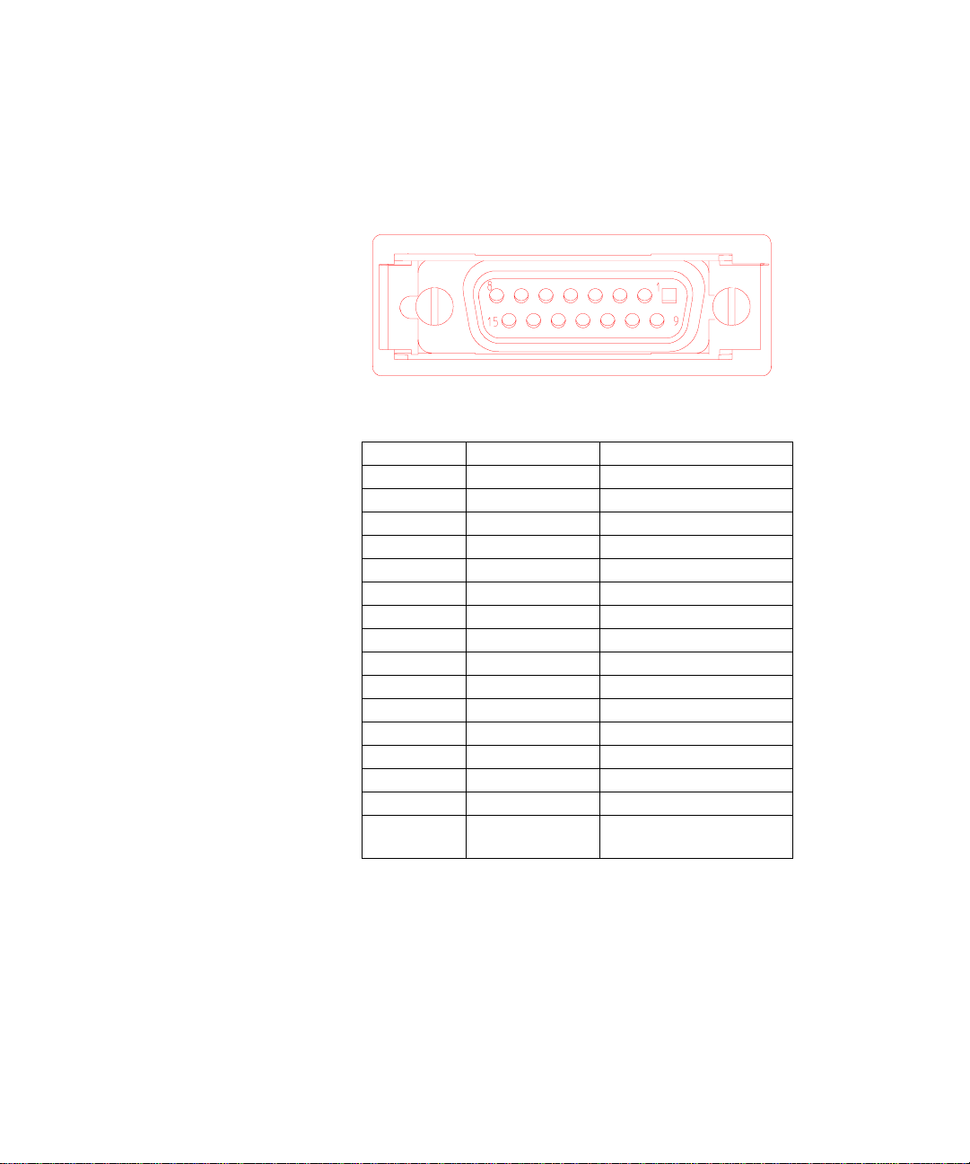
RS-232C/V.24
Breakout Box, LEDs, and Connectors B
Pin CCITT
Circuit
1 101 Protective Ground 14 118 Secondary
2 103 Transmitted Data 15 114 Transmission Si gn al
3 104 Rece i ved Data 16 119 S econdary Received
4 105 Request to Send 17 115 Receiver Signal
5 106 Clear to Send 18 Unassigned
6 107 Data Set Ready 19 120 Secondary Reques t
7 102 S ignal Ground
8 109 R eceived Line Signal
9 (Reserved for Data Set
10 (Reserved for Data Set
11 Unassigned 24 113 Transmit Signal
12 122 Secondary Received
13 121 Secondary Clear to
Circuit Function Pin CCITT
Circuit
20 108.2 Data Terminal Ready
(common return)
21 110 Signal Quality
Detector
22 125 Ring Indicator
Testing)
23 111/112 Data Signal Rate
Testing)
25 Unassigned
Line Signal Detector
Send
Circuit Function
Transmitted Data
Element T i min g ( DC E
Source)
Data
Element T i min g ( DC E
Source)
to Send
Detector
Selector (DTE
Source)
Element Timing (DTE
Source)
Advisor Mainframe Features System Guide 67
B Breakout Box , LEDs, and Connec to rs
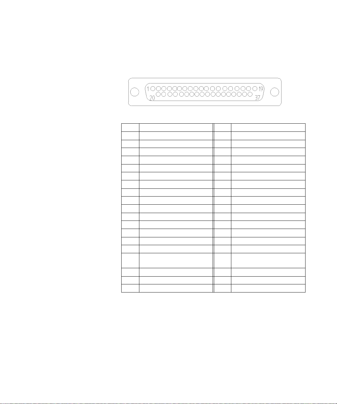
RS-449
Pin Circuit Name Pin Circuit Name
1 Shield 20 Receive Common
2Send Timing 21Spare
3Spare 22Send Data
4 Send Data 23 Send Timing
5Send Timing 24Receive Data
6 Receive Data 25 Request to Send
7 Request to Send 26 Rece ive Timing
8 Receive Timing 27 Clear to Send
9 Clear to Send 28 Terminal in Service
10 Local Loopback 29 Data Mode
11 Data Mode 30 Terminal Ready
12 Terminal Ready 31 Rece i ve r Ready
13 Receiver Ready 32 Select Standby
14 Remote Loopback 33 Signal Quality
15 Incoming Call 34 New Signal
16 Select Frequency/Signal Rate
17 Terminal Timing 36 Standby Indicator
18 Test Mode 37 Send Common
19 Signal Ground
35 Terminal Ti ming
Selector
68 Advisor Mainf ra me Features System Gui de
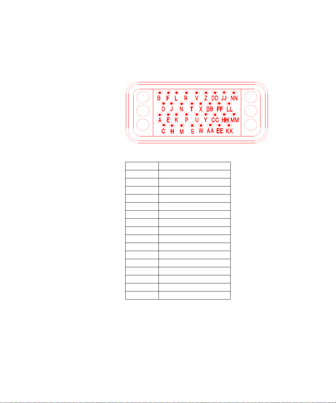
V.35
Breakout Box, LEDs, and Connectors B
Pin Circuit Name
A Chassis Ground
B Signal Ground
C Request to Send
DClear to Send
E Data Set Ready
F Receive Line Signal Detect
P Transmit Data (A)
R Received Data (A)
S Transmit Data (B)
T Received Data (B)
U Terminal Timing (A)
V Receive Timing (A)
W Terminal Timing (B)
X Receive Timing (A)
Y Transmit Timing (A)
AA Transmit Timing (B)
Advisor Mainframe Features System Guide 69

B Breakout Box , LEDs, and Connec to rs
Interface Pin-Out Comparison
RS-232C/CCITT V.24 CCITT V.35 RS-449
25 Pin 34 Pin 37 Pin
1–Protective Ground A–Protective Ground 1–Shield
2–Transmitted Data P–Transmit Data (A)
3–Received Data R–Received Data (A)
4–Request to Send C–Request to Send 7–Request to Send (A)
5–Clear to Send D–Clear to Send 9–Clear to Send (A)
6–Data Set Ready E–Data Set Ready 11–Data Mode (A)
7–Signal Ground B–Signal Ground 19–Signal Ground
8–Carrier Detect F–Receive L i ne Signal
9–Reserved for Testing m–Reserved for DSU
10–Reserved for Testing 10–Local Loop (A)
11–Unassigned 3–Spare
12–Sec. Carrier Detect 32–Se lect Sta ndby
13–Sec. Clear to Send
14–Sec. Trans m it ted
Data
15–Transmit Clock (DCE
Source)
16–Sec. Received Data
S–Transmit Data (B)
T–Received Data (B)
Detect
Testing
Y–TX Signal Element
Timing
o–TX Signal Element
Timing
37–Send Common
4–Send Data (A)
22–Send Data (B)
6–Received Data(A)
24–Received Data (B)
25–Request to Send (B)
27–Clear to Send (B)
29–Data Mode (B)
13–Receiver Ready (A)
31–Receiver Ready (B)
20–Receive Common
14–Remote Loop (B)
21–Spare
5–Send Timing (A) DCE Source
23–Send Timing (B) DCE
Source
70 Advisor Mainf ra me Features System Gui de

Breakout Box, LEDs, and Connectors B
RS-232C/CCITT V.24 CCITT V.35 RS-449
25 Pin 34 Pin 37 Pin
17–Receive Clock V–RX Signal Element
X–RX Signal Element
18–Unassigned 18–Test Mode (A)
19–Sec. Request to Send
20–Data Terminal Ready 12–Terminal Ready (A)
21–Signal Quality
Detector
22–Ring Indicator 15–Incoming Call (A)
23–Data Signal Ra t e
Selector
24–Transmit Clock (DTE
Source)
25–Busy 36–Stand by Indicator
8–Receive Timing (A)
26–Receive Timing (B)
28–Term in Service (A)
34–New Signal
30–Terminal Ready (B)
33–Signal Quality (A)
2–Signaling Rate Indicato r (A)
16–Signaling Rate Selector (A)
17–Terminal Timing (A)
35–Terminal Timing (B)
Advisor Mainframe Features System Guide 71
B Breakout Box , LEDs, and Connec to rs
AUI — 100Base-T
Pin Circuit Name Use
1 CI-S Control In circuit Shield
2 CI-A Control In circuit A
3 DO-A Data Out circuit A
4 DI-S Data In circuit Shield
5 DI-A Data In circuit A
6VC Voltage Common
7 CO-A Control Out circuit A
8 CO-S Control Out circuit Shield
9 CI-B Control In circuit B
10 DO-B Data Out circuit B
11 DO-S Dat a O u t circuit Shie ld
12 DI-B Data In circuit B
13 VP Voltage Plus
14 VS Voltage Shield
15 CO-B Control Out circuit B
SHELL PG Protection Gr ou nd
(Conductive Shell)
72 Advisor Mainf ra me Features System Gui de

MII — 100Base-T
Breakout Box, LEDs, and Connectors B
Pin Circuit Name Pin Circuit Name
1 +5 V 21 +5 V
2 MDIO 22 COMMON
3 MDC 23 COMMON
4 RXD<3> 24 COMMON
5 RXD<2> 25 COMMON
6 RXD<1> 26 COMMON
7 RXD<0> 27 COMMON
8 RX_DV 28 COMMON
9 RX_CLK 29 COMMON
10 RX_ER 30 COMMON
11 TX_ER 31 COMMON
12 TX_CLK 32 COMMON
13 TX_EN 33 COMMON
14 TXD<0> 34 COMMON
15 TXD<1> 35 COMMON
16 TXD<2> 36 COMMON
17 TXD<3> 37 COMMON
18 COL 38 COMMON
19 CRS 39 COMMON
20 +5 V 40 +5 V
Advisor Mainframe Features System Guide 73

B Breakout Box , LEDs, and Connec to rs
MDI — 100Base-TX
Pin Circuit Name
1TX_D1+
2TX_D13RX_D2+
4BI_D3+
5BI_D36RX_D27BI_D4+
8BI_D4-
Crossover
Function
74 Advisor Mainf ra me Features System Gui de

C
Regulatory Information
Declarations of Conformity 76
Laser Safety Statemen ts 110
Safety Information for Laser Source Modules 111
Agilent Technologies
75

C Regulatory Information
Declarations of Conformity
J1990A Full Duplex Ethernet T ap
DECLARATION OF CONFORMITY
According to ISO/IEC Guide 22 and CEN/CENELEC EN 45014
Manufacturer’s Name:
Manufacturer’s Address:
Declares that the product,
Product Name:
Model Number:
Product Options:
Conforms with the following product standards:
EMC
(Technical
Construction
File)
Safety IEC 61010-1:1990 + A1:1992 + A2:1995 / EN 61010-1:1993 + A2:1995
Supplemental Information:
27 November 2001
Date
For further information, please contact your local Agilent Technologies sales office, agent, or distributor.
Revision: A.00.00 Issue Date: 27 NOV 2001 Document No. J1990A-DoC-A.00.00
Agilent Technologies, Inc.
Network Systems Test Division (NSTD)
5070 Centennial Boulevard
Colorado Springs, Colorado 80919
United States of America
Full Duplex Ethernet Tap
J1990A
This declaration covers all options of the above product.
The product herewith complies with the requirements of the EMC Directive 89/336/EEC
(including 93/68/EEC) and carries the CE Marking accordingly (European Union).
Against: EMC test specifications EN 55011:1991 (Group 1, Class A) and EN 61326:1997
As detailed in: Electromagnetic Compatibility (EMC) Certificate of Conformance Report No.
Assessed by: EMC Test Center, York EMC Services Limited Appointed Competent Body
Fleming Building
Donibristle Industrial Park
Dalgety Bay
Canada: CSA C22.2 No. 1010.1:1992
1080/1/CBR, based on Technical Construction File (TCF) No. NSTD-EMC
Program reference A-2961-2388-100 Revision A, dated 6 June 2001.
Dunfermine, Fife KY11 9HZ United Kingdom
Neil Yosinski
Name
Regulatory Manager
Title
76 Advisor Mainf ra me Features System Gui de

J2294C CEPT-E1 DB9 & RJ-45 Interface Module
DECLARATION OF CONFORMITY
According to ISO/IEC Guide 22 and CEN/CENELEC EN 45014
Manu fact urer ’s N ame:
Manu fact urer ’s Ad dres s:
Decl ares tha t th e pr oduc t,
Produ ct Na me:
Mode l Num ber:
Produ ct O ption s:
Conf orms with the fo llow ing product standards:
EMC
(Tec hnica l
Cons truct ion
File )
Safet y
Supp leme ntal Information:
19 February 2002
Date
For further information, please contact your local Agilent Technologies sales office, agent, or distributor.
Revision: A.00.00 Issue Date: 19 FEB 2002 Document No. J2294C-DoC-A.00.00
Agilent Technologies, Inc.
Network Systems Test Division (NSTD)
5070 Centennial Boulevard
Colorado Springs, Colorado 80919
United States of America
CEPT-E1 DB9 & RJ-45 Balanced Module
J2294C
This declaration covers all options of the above product.
The product herewith complies with the requirements of the EMC Directive 89/336/EEC
(including 93/68/EEC) and carries the CE Marking accordingly (European Union).
Against: EMC test specifications EN 55011:1991 (Group 1, Class A) and EN 61326:1997
As detailed in: Electromagnetic Compatibility (EMC) Certificate of Conformance Report No.
Assessed by: EMC Test Center, York EMC Services Limited Appointed Competent Body
Fleming Building
Donibristle Industrial Park
Dalgety Bay
IEC 61010-1:1990 + A1:1992 + A2:1995 / EN 61010-1:1993 + A2:1995
Canada: CSA C22.2 No. 1010.1:1992
1080/1/CBR, based on Technical Construction File (TCF) No. NSTD-EMC
Program reference A-2961-2388-100 Revision A, dated 6 June 2001.
Dunfermine, Fife KY11 9HZ United Kingdom
Neil Yosinski
Name
Regulatory Manager
Title
Regulato ry Informatio n C
Advisor Mainframe Features System Guide 77

C Regulatory Information
J2294D, J2296D, J2298D E1 and T1 Interface Modules
DECLARATION OF CONFORMITY
According to ISO/IEC Guide 22 and CEN/CENELEC EN 45014
Manu fact urer ’s N ame:
Manu fact urer ’s Ad dres s:
Decl ares tha t th e pr oduc ts,
Produ ct Na mes:
Mode l Num bers:
Produ ct O ption s:
Conf orm with the fol low ing product standards :
EMC
(Tec hnica l
Cons truct ion
File )
Safet y
Supp leme ntal Information:
19 February 2002
Date
For further information, please contact your local Agilent Technologies sales office, agent, or distributor.
Revision: A.00.00 Issue Date: 19 FEB 2002 Document No. J229xD-DoC-A.00.00
Agilent Technologies, Inc.
Network Systems Test Division (NSTD)
5070 Centennial Boulevard
Colorado Springs, Colorado 80919
United States of America
E1/T1 DB-9 / RJ-45, E1 BNC 75 ohms, and E1/T1 RJ-45/RJ-48C/minibantam Interface Modules
J2294D, J2296D, and J2298D
This declaration covers all options of the above product.
The product herewith complies with the requirements of the EMC Directive 89/336/EEC
(including 93/68/EEC) and carries the CE Marking accordingly (European Union).
Against: EMC test specifications EN 55011:1991 (Group 1, Class A) and EN 61326:1997
As detailed in: Electromagnetic Compatibility (EMC) Certificate of Conformance Report No.
Assessed by: EMC Test Center, York EMC Services Limited Appointed Competent Body
Fleming Building
Donibristle Industrial Park
Dalgety Bay
IEC 61010-1:1990 + A1:1992 + A2:1995 / EN 61010-1:1993 + A2:1995
Canada: CSA C22.2 No. 1010.1:1992
1080/1/CBR, based on Technical Construction File (TCF) No. NSTD-EMC
Program reference A-2961-2388-100 Revision A, dated 6 June 2001.
Dunfermine, Fife KY11 9HZ United Kingdom
Neil Yosinski
Name
Regulatory Manager
Title
78 Advisor Mainf ra me Features System Gui de

J2300D Advisor WAN
Manu fact urer ’s N ame:
Manu fact urer ’s Ad dres s:
Decl ares tha t th e pr oduc t,
Produ ct Na me:
Mode l Num ber:
Produ ct O ption s:
Conf orms with the fo llow ing product standards:
EMC
(Tec hnica l
Cons truct ion
File )
Safet y
Supp leme ntal Information:
19 February 2002
Date
For further information, please contact your local Agilent Technologies sales office, agent, or distributor.
Revision: A.00.00 Issue Date: 19 FEB 2002 Document No. J2300D-DoC-A.00.00
The product herewith complies with the requirements of the EMC Directive 89/336/EEC
(including 93/68/EEC) and carries the CE Marking accordingly (European Union).
Against: EMC test specifications EN 55011:1991 (Group 1, Class A) and EN 61326:1997
As detailed in: Electromagnetic Compatibility (EMC) Certificate of Conformance Report No.
Assessed by: EMC Test Center, York EMC Services Limited Appointed Competent Body
Fleming Building
Donibristle Industrial Park
Dalgety Bay
IEC 61010-1:1990 + A1:1992 + A2:1995 / EN 61010-1:1993 + A2:1995
Canada: CSA C22.2 No. 1010.1:1992
Regulato ry Informatio n C
DECLARATION OF CONFORMITY
According to ISO/IEC Guide 22 and CEN/CENELEC EN 45014
Agilent Technologies, Inc.
Network Systems Test Division (NSTD)
5070 Centennial Boulevard
Colorado Springs, Colorado 80919
United States of America
Agilent Advisor - WAN
J2300D
This declaration covers all options of the above product.
1080/1/CBR, based on Technical Construction File (TCF) No. NSTD-EMC
Program reference A-2961-2388-100 Revision A, dated 6 June 2001.
Dunfermine, Fife KY11 9HZ United Kingdom
Neil Yosinski
Name
Regulatory Manager
Title
Advisor Mainframe Features System Guide 79

C Regulatory Information
J2300E Advisor WAN
DECLARATION OF CONFORMITY
According to ISO/IEC Guide 22 and CEN/CENELEC EN 45014
Manu fact urer ’s N ame:
Manu fact urer ’s Ad dres s:
Decl ares tha t th e pr oduc t,
Produ ct Na me:
Mode l Num ber:
Produ ct O ption s:
Conf orms with the fo llow ing product standards:
EMC
(Tec hnica l
Cons truct ion
File )
Safet y
Supp leme ntal Information:
19 February 2002
Date
For further information, please contact your local Agilent Technologies sales office, agent, or distributor.
Revision: A.00.00 Issue Date: 19 FEB 2002 Document No. J2300E-DoC-A.00.00
Agilent Technologies, Inc.
Network Systems Test Division (NSTD)
5070 Centennial Boulevard
Colorado Springs, Colorado 80919
United States of America
Agilent Advisor - WAN
J2300E
This declaration covers all options of the above product.
The product herewith complies with the requirements of the EMC Directive 89/336/EEC
(including 93/68/EEC) and carries the CE Marking accordingly (European Union).
Against: EMC test specifications EN 55011:1991 (Group 1, Class A) and EN 61326:1997
As detailed in: Electromagnetic Compatibility (EMC) Certificate of Conformance Report No.
Assessed by: EMC Test Center, York EMC Services Limited Appointed Competent Body
Fleming Building
Donibristle Industrial Park
Dalgety Bay
IEC 61010-1:1990 + A1:1992 + A2:1995 / EN 61010-1:1993 + A2:1995
Canada: CSA C22.2 No. 1010.1:1992
1080/1/CBR, based on Technical Construction File (TCF) No. NSTD-EMC
Program reference A-2961-2388-100 Revision A, dated 6 June 2001.
Dunfermine, Fife KY11 9HZ United Kingdom
Neil Yosinski
Name
Regulatory Manager
Title
80 Advisor Mainf ra me Features System Gui de

Regulato ry Informatio n C
J2306B, J2309B LAN Ethernet and Eth/Token Ring Undercradle
DECLARATION OF CONFORMITY
According to ISO/IEC Guide 22 and CEN/CENELEC EN 45014
Manu fact urer ’s N ame:
Manu fact urer ’s Ad dres s:
Decl ares tha t th e pr oduc t,
Produ ct Na me:
Mode l Num ber:
Produ ct O ption s:
Conf orms with the fo llow ing product standards:
EMC
(Tec hnica l
Cons truct ion
File )
Safet y
Supp leme ntal Information:
21 February 2002
Date
For further information, please contact your local Agilent Technologies sales office, agent, or distributor.
Revision: A.00.00 Issue Date: 21 FEB 2002 Document No. J230xB-DoC-A.00.00
Agilent Technologies, Inc.
Network Systems Test Division (NSTD)
5070 Centennial Boulevard
Colorado Springs, Colorado 80919
United States of America
Agilent Advisor LAN - Ethernet and Ethernet/Token Ring undercradles
J2306B and J2309B
This declaration covers all options of the above product.
The product herewith complies with the requirements of the EMC Directive 89/336/EEC
(including 93/68/EEC) and carries the CE Marking accordingly (European Union).
Against: EMC test specifications EN 55011:1991 (Group 1, Class A) and EN 61326:1997
As detailed in: Electromagnetic Compatibility (EMC) Certificate of Conformance Report No.
Assessed by: EMC Test Center, York EMC Services Limited Appointed Competent Body
Fleming Building
Donibristle Industrial Park
Dalgety Bay
IEC 61010-1:1990 + A1:1992 + A2:1995 / EN 61010-1:1993 + A2:1995
Canada: CSA C22.2 No. 1010.1:1992
1080/1/CBR, based on Technical Construction File (TCF) No. NSTD-EMC
Program reference A-2961-2388-100 Revision A, dated 6 June 2001.
Dunfermine, Fife KY11 9HZ United Kingdom
Neil Yosinski
Name
Regulatory Manager
Title
Advisor Mainframe Features System Guide 81

C Regulatory Information
J2307A LAN Token Ring Undercradle
DECLARATION OF CONFORMITY
According to ISO/IEC Guide 22 and CEN/CENELEC EN 45014
Manu fact urer ’s N ame:
Manu fact urer ’s Ad dres s:
Decl ares tha t th e pr oduc t,
Produ ct Na me:
Mode l Num ber:
Produ ct O ption s:
Conf orms with the fo llow ing product standards:
EMC
(Tec hnica l
Cons truct ion
File )
Safet y
Supp leme ntal Information:
19 February 2002
Date
For further information, please contact your local Agilent Technologies sales office, agent, or distributor.
Revision: A.00.00 Issue Date: 19 FEB 2002 Document No. J2307A-DoC-A.00.00
Agilent Technologies, Inc.
Network Systems Test Division (NSTD)
5070 Centennial Boulevard
Colorado Springs, Colorado 80919
United States of America
LAN - Token Ring undercradle
J2307A
This declaration covers all options of the above product.
The product herewith complies with the requirements of the EMC Directive 89/336/EEC
(including 93/68/EEC) and carries the CE Marking accordingly (European Union).
Against: EMC test specifications EN 55011:1991 (Group 1, Class A) and EN 61326:1997
As detailed in: Electromagnetic Compatibility (EMC) Certificate of Conformance Report No.
Assessed by: EMC Test Center, York EMC Services Limited Appointed Competent Body
Fleming Building
Donibristle Industrial Park
Dalgety Bay
IEC 61010-1:1990 + A1:1992 + A2:1995 / EN 61010-1:1993 + A2:1995
Canada: CSA C22.2 No. 1010.1:1992
1080/1/CBR, based on Technical Construction File (TCF) No. NSTD-EMC
Program reference A-2961-2388-100 Revision A, dated 6 June 2001.
Dunfermine, Fife KY11 9HZ United Kingdom
Neil Yosinski
Name
Regulatory Manager
Title
82 Advisor Mainf ra me Features System Gui de

J2524A FDDI Undercradle
According to ISO/IEC Guide 22 and CEN/CENELEC EN 45014
Manu fact urer ’s N ame:
Manu fact urer ’s Ad dres s:
Decl ares tha t th e pr oduc t,
Produ ct Na me:
Mode l Num ber:
Produ ct O ption s:
Conf orms with the fo llow ing product standards:
EMC
(Tec hnica l
Cons truct ion
File )
Safet y
Supp leme ntal Information:
19 February 2002
Date
For further information, please contact your local Agilent Technologies sales office, agent, or distributor.
Revision: A.00.00 Issue Date: 19 FEB 2002 Document No. J2524A-DoC-A.00.00
Agilent Advisor LAN - FDDI undercradle
J2524A
This declaration covers all options of the above product.
The product herewith complies with the requirements of the EMC Directive 89/336/EEC
(including 93/68/EEC) and carries the CE Marking accordingly (European Union).
Against: EMC test specifications EN 55011:1991 (Group 1, Class A) and EN 61326:1997
As detailed in: Electromagnetic Compatibility (EMC) Certificate of Conformance Report No.
Assessed by: EMC Test Center, York EMC Services Limited Appointed Competent Body
Fleming Building
Donibristle Industrial Park
Dalgety Bay
IEC 61010-1:1990 + A1:1992 + A2:1995 / EN 61010-1:1993 + A2:1995
Canada: CSA C22.2 No. 1010.1:1992
Regulato ry Informatio n C
DECLARATION OF CONFORMITY
Agilent Technologies, Inc.
Network Systems Test Division (NSTD)
5070 Centennial Boulevard
Colorado Springs, Colorado 80919
United States of America
1080/1/CBR, based on Technical Construction File (TCF) No. NSTD-EMC
Program reference A-2961-2388-100 Revision A, dated 6 June 2001.
Dunfermine, Fife KY11 9HZ United Kingdom
Neil Yosinski
Name
Regulatory Manager
Title
Advisor Mainframe Features System Guide 83

C Regulatory Information
J2527A TIMS Undercradle
DECLARATION OF CONFORMITY
According to ISO/IEC Guide 22 and CEN/CENELEC EN 45014
Manu fact urer ’s N ame:
Manu fact urer ’s Ad dres s:
Decl ares tha t th e pr oduc t,
Produ ct Na me:
Mode l Num ber:
Produ ct O ption s:
Conf orms with the fo llow ing product standards:
EMC
(Tec hnica l
Cons truct ion
File )
Safet y
Supp leme ntal Information:
19 February 2002
Date
For further information, please contact your local Agilent Technologies sales office, agent, or distributor.
Revision: A.00.00 Issue Date: 19 FEB 2002 Document No. J2527A-DoC-A.00.00
Agilent Technologies, Inc.
Network Systems Test Division (NSTD)
5070 Centennial Boulevard
Colorado Springs, Colorado 80919
United States of America
Agilent Advisor - TIMS undercradle
J2527A
This declaration covers all options of the above product.
The product herewith complies with the requirements of the EMC Directive 89/336/EEC
(including 93/68/EEC) and carries the CE Marking accordingly (European Union).
Against: EMC test specifications EN 55011:1991 (Group 1, Class A) and EN 61326:1997
As detailed in: Electromagnetic Compatibility (EMC) Certificate of Conformance Report No.
Assessed by: EMC Test Center, York EMC Services Limited Appointed Competent Body
Fleming Building
Donibristle Industrial Park
Dalgety Bay
IEC 61010-1:1990 + A1:1992 + A2:1995 / EN 61010-1:1993 + A2:1995
Canada: CSA C22.2 No. 1010.1:1992
1080/1/CBR, based on Technical Construction File (TCF) No. NSTD-EMC
Program reference A-2961-2388-100 Revision A, dated 6 June 2001.
Dunfermine, Fife KY11 9HZ United Kingdom
Neil Yosinski
Name
Regulatory Manager
Title
84 Advisor Mainf ra me Features System Gui de

J2900A High Speed Acquisition Undercradle
DECLARATION OF CONFORMITY
According to ISO/IEC Guide 22 and CEN/CENELEC EN 45014
Manu fact urer ’s N ame:
Manu fact urer ’s Ad dres s:
Decl ares tha t th e pr oduc t,
Produ ct Na me:
Mode l Num ber:
Produ ct O ption s:
Conf orms with the fo llow ing product standards:
EMC
(Tec hnica l
Cons truct ion
File )
Safet y
Supp leme ntal Information:
19 February 2002
Date
For further information, please contact your local Agilent Technologies sales office, agent, or distributor.
Revision: A.00.00 Issue Date: 19 FEB 2002 Document No. J2900A-DoC-A.00.00
Agilent Technologies, Inc.
Network Systems Test Division (NSTD)
5070 Centennial Boulevard
Colorado Springs, Colorado 80919
United States of America
Agilent Advisor - High Speed Acquisition undercradle
J2900A
This declaration covers all options of the above product.
The product herewith complies with the requirements of the EMC Directive 89/336/EEC
(including 93/68/EEC) and carries the CE Marking accordingly (European Union).
Against: EMC test specifications EN 55011:1991 (Group 1, Class A) and EN 61326:1997
As detailed in: Electromagnetic Compatibility (EMC) Certificate of Conformance Report No.
Assessed by: EMC Test Center, York EMC Services Limited Appointed Competent Body
Fleming Building
Donibristle Industrial Park
Dalgety Bay
IEC 61010-1:1990 + A1:1992 + A2:1995 / EN 61010-1:1993 + A2:1995
Canada: CSA C22.2 No. 1010.1:1992
1080/1/CBR, based on Technical Construction File (TCF) No. NSTD-EMC
Program reference A-2961-2388-100 Revision A, dated 6 June 2001.
Dunfermine, Fife KY11 9HZ United Kingdom
Neil Yosinski
Name
Regulatory Manager
Title
Regulato ry Informatio n C
Advisor Mainframe Features System Guide 85

C Regulatory Information
J2901A Gigabit Ethernet Undercradle
DECLARATION OF CONFORMITY
According to ISO/IEC Guide 22 and CEN/CENELEC EN 45014
Manu fact urer ’s N ame:
Manu fact urer ’s Ad dres s:
Decl ares tha t th e pr oduc ts,
Produ ct Na me:
Mode l Num ber:
Produ ct O ption s:
Conf orm with the fol low ing product standards :
EMC
(Tec hnica l
Cons truct ion
File )
Safet y
Laser /LED
Supp leme ntal Information:
19 February 2002
Date
For further information, please contact your local Agilent Technologies sales office, agent, or distributor.
Revision: A.00.00 Issue Date: 19 FEB 2002 Document No. J2901A-DoC-A.00.00
Agilent Technologies, Inc.
Network Systems Test Division (NSTD)
5070 Centennial Boulevard
Colorado Springs, Colorado 80919
United States of America
Agilent Advisor LAN - Gigabit Ethernet undercradle
J2901A
This declaration covers all options of the above products.
The product herewith complies with the requirements of the EMC Directive 89/336/EEC
(including 93/68/EEC) and carries the CE Marking accordingly (European Union).
Against: EMC test specifications EN 55011:1991 (Group 1, Class A) and EN 61326:1997
As detailed in: Electromagnetic Compatibility (EMC) Certificate of Conformance Report No.
Assessed by: EMC Test Center, York EMC Services Limited Appointed Competent Body
Fleming Building
Donibristle Industrial Park
Dalgety Bay
IEC 61010-1:1990 + A1:1992 + A2:1995 / EN 61010-1:1993 + A2:1995
Canada: CSA C22.2 No. 1010.1:1992
IEC 60825-1:1993 + A1:1997 / EN 60825-1:1994 + A11:1996 Class 1
1080/1/CBR, based on Technical Construction File (TCF) No. NSTD-EMC
Program reference A-2961-2388-100 Revision A, dated 6 June 2001.
Dunfermine, Fife KY11 9HZ United Kingdom
Neil Yosinski
Name
Regulatory Manager
Title
86 Advisor Mainf ra me Features System Gui de
Regulato ry Informatio n C
J2904B, J2293B/94B/96B/97B/98B/99B ISDN/BERT Interface Modules
DECLARATION OF CONFORMITY
According to ISO/IEC Guide 22 and CEN/CENELEC EN 45014
Manu fact urer ’s N ame:
Manu fact urer ’s Ad dres s:
Decl ares tha t th e pr oduc ts,
Produ ct Na mes:
Mode l Num bers:
Produ ct O ption s:
Conf orm with the fol low ing product standards :
EMC
(Tec hnica l
Cons truct ion
File )
Safet y
Supp leme ntal Information:
19 February 2002
Date
For further information, please contact your local Agilent Technologies sales office, agent, or distributor.
Revision: A.00.00 Issue Date: 19 FEB 2002 Document No. J2904B-DoC-A.00.00
Agilent Technologies, Inc.
Network Systems Test Division (NSTD)
5070 Centennial Boulevard
Colorado Springs, Colorado 80919
United States of America
ISDN BRI S/T Simulation/BERT, CEPT-E1 DB9 75-ohm unbalanced,
CEPT-E1 DB9 120-ohm balanced, CEPT-E1 BNC, CEPT-E1 BR-2, T1
RJ-48C/mini-bantam, and T1 RJ-45/mini-bantam Interface Modules
J2904B, J2293B, J2294B, J2296B, J2297B, J2298B, and J2299B
This declaration covers all options of the above product.
The product herewith complies with the requirements of the EMC Directive 89/336/EEC
(including 93/68/EEC) and carries the CE Marking accordingly (European Union).
Against: EMC test specifications EN 55011:1991 (Group 1, Class A) and EN 61326:1997
As detailed in: Electromagnetic Compatibility (EMC) Certificate of Conformance Report No.
Assessed by: EMC Test Center, York EMC Services Limited Appointed Competent Body
Fleming Building
Donibristle Industrial Park
Dalgety Bay
IEC 61010-1:1990 + A1:1992 + A2:1995 / EN 61010-1:1993 + A2:1995
Canada: CSA C22.2 No. 1010.1:1992
1080/1/CBR, based on Technical Construction File (TCF) No. NSTD-EMC
Program reference A-2961-2388-100 Revision A, dated 6 June 2001.
Dunfermine, Fife KY11 9HZ United Kingdom
Neil Yosinski
Name
Regulatory Manager
Title
Advisor Mainframe Features System Guide 87
C Regulatory Information
J2905B ISDN BRI S/T and U Interface Module
DECLARATION OF CONFORMITY
According to ISO/IEC Guide 22 and CEN/CENELEC EN 45014
Manu fact urer ’s N ame:
Manu fact urer ’s Ad dres s:
Decl ares tha t th e pr oduc t,
Produ ct Na me:
Mode l Num ber:
Produ ct O ption s:
Conf orms with the fo llow ing product standards:
EMC
(Tec hnica l
Cons truct ion
File )
Safet y
Supp leme ntal Information:
19 February 2002
Date
For further information, please contact your local Agilent Technologies sales office, agent, or distributor.
Revision: A.00.00 Issue Date: 19 FEB 2002 Document No. J2905B-DoC-A.00.00
Agilent Technologies, Inc.
Network Systems Test Division (NSTD)
5070 Centennial Boulevard
Colorado Springs, Colorado 80919
United States of America
ISDN BRI S/T and U Interface Module
J2905B
This declaration covers all options of the above product.
The product herewith complies with the requirements of the EMC Directive 89/336/EEC
(including 93/68/EEC) and carries the CE Marking accordingly (European Union).
Against: EMC test specifications EN 55011:1991 (Group 1, Class A) and EN 61326:1997
As detailed in: Electromagnetic Compatibility (EMC) Certificate of Conformance Report No.
Assessed by: EMC Test Center, York EMC Services Limited Appointed Competent Body
Fleming Building
Donibristle Industrial Park
Dalgety Bay
IEC 61010-1:1990 + A1:1992 + A2:1995 / EN 61010-1:1993 + A2:1995
Canada: CSA C22.2 No. 1010.1:1992
1080/1/CBR, based on Technical Construction File (TCF) No. NSTD-EMC
Program reference A-2961-2388-100 Revision A, dated 6 June 2001.
Dunfermine, Fife KY11 9HZ United Kingdom
Neil Yosinski
Name
Regulatory Manager
Title
88 Advisor Mainf ra me Features System Gui de

J2908A DDS 4-Wire Interface Module
DECLARATION OF CONFORMITY
According to ISO/IEC Guide 22 and CEN/CENELEC EN 45014
Manu fact urer ’s N ame:
Manu fact urer ’s Ad dres s:
Decl ares tha t th e pr oduc t,
Produ ct Na me:
Mode l Num ber:
Produ ct O ption s:
Conf orms with the fo llow ing product standards:
EMC
(Tec hnica l
Cons truct ion
File )
Safet y
Supp leme ntal Information:
19 February 2002
Date
For further information, please contact your local Agilent Technologies sales office, agent, or distributor.
Revision: A.00.00 Issue Date: 19 FEB 2002 Document No. J2908A-DoC-A.00.00
Agilent Technologies, Inc.
Network Systems Test Division (NSTD)
5070 Centennial Boulevard
Colorado Springs, Colorado 80919
United States of America
Agilent Advisor - DDS 4-wire Module
J2908A
This declaration covers all options of the above product.
The product herewith complies with the requirements of the EMC Directive 89/336/EEC
(including 93/68/EEC) and carries the CE Marking accordingly (European Union).
Against: EMC test specifications EN 55011:1991 (Group 1, Class A) and EN 61326:1997
As detailed in: Electromagnetic Compatibility (EMC) Certificate of Conformance Report No.
Assessed by: EMC Test Center, York EMC Services Limited Appointed Competent Body
Fleming Building
Donibristle Industrial Park
Dalgety Bay
IEC 61010-1:1990 + A1:1992 + A2:1995 / EN 61010-1:1993 + A2:1995
Canada: CSA C22.2 No. 1010.1:1992
1080/1/CBR, based on Technical Construction File (TCF) No. NSTD-EMC
Program reference A-2961-2388-100 Revision A, dated 6 June 2001.
Dunfermine, Fife KY11 9HZ United Kingdom
Neil Yosinski
Name
Regulatory Manager
Title
Regulato ry Informatio n C
Advisor Mainframe Features System Guide 89

C Regulatory Information
J2909A ATM DS-3/E3 Interface Module
DECLARATION OF CONFORMITY
According to ISO/IEC Guide 22 and CEN/CENELEC EN 45014
Manu fact urer ’s N ame:
Manu fact urer ’s Ad dres s:
Decl ares tha t th e pr oduc t,
Produ ct Na me:
Mode l Num ber:
Produ ct O ption s:
Conf orms with the fo llow ing product standards:
EMC
(Tec hnica l
Cons truct ion
File )
Safet y
Supp leme ntal Information:
19 February 2002
Date
For further information, please contact your local Agilent Technologies sales office, agent, or distributor.
Revision: A.00.00 Issue Date: 19 FEB 2002 Document No. J2909A-DoC-A.00.00
Agilent Technologies, Inc.
Network Systems Test Division (NSTD)
5070 Centennial Boulevard
Colorado Springs, Colorado 80919
United States of America
Agilent Advisor ATM - DS-3/E3 Module
J2909A
This declaration covers all options of the above product.
The product herewith complies with the requirements of the EMC Directive 89/336/EEC
(including 93/68/EEC) and carries the CE Marking accordingly (European Union).
Against: EMC test specifications EN 55011:1991 (Group 1, Class A) and EN 61326:1997
As detailed in: Electromagnetic Compatibility (EMC) Certificate of Conformance Report No.
Assessed by: EMC Test Center, York EMC Services Limited Appointed Competent Body
Fleming Building
Donibristle Industrial Park
Dalgety Bay
IEC 61010-1:1990 + A1:1992 + A2:1995 / EN 61010-1:1993 + A2:1995
Canada: CSA C22.2 No. 1010.1:1992
1080/1/CBR, based on Technical Construction File (TCF) No. NSTD-EMC
Program reference A-2961-2388-100 Revision A, dated 6 June 2001.
Dunfermine, Fife KY11 9HZ United Kingdom
Neil Yosinski
Name
Regulatory Manager
Title
90 Advisor Mainf ra me Features System Gui de

J2912A ATM OC-3c/STM-1 Interface Module
DECLARATION OF CONFORMITY
According to ISO/IEC Guide 22 and CEN/CENELEC EN 45014
Manu fact urer ’s N ame:
Manu fact urer ’s Ad dres s:
Decl ares tha t th e pr oduc ts,
Produ ct Na me:
Mode l Num ber:
Produ ct O ption s:
Conf orm with the fol low ing product standards :
EMC
(Tec hnica l
Cons truct ion
File )
Safet y
Laser /LED
Supp leme ntal Information:
19 February 2002
Date
For further information, please contact your local Agilent Technologies sales office, agent, or distributor.
Revision: A.00.00 Issue Date: 19 FEB 2002 Document No. J2912A-DoC-A.00.00
Agilent Technologies, Inc.
Network Systems Test Division (NSTD)
5070 Centennial Boulevard
Colorado Springs, Colorado 80919
United States of America
Agilent Advisor ATM - OC-3c / STM-1 module
J2912A
This declaration covers all options of the above products.
The product herewith complies with the requirements of the EMC Directive 89/336/EEC
(including 93/68/EEC) and carries the CE Marking accordingly (European Union).
Against: EMC test specifications EN 55011:1991 (Group 1, Class A) and EN 61326:1997
As detailed in: Electromagnetic Compatibility (EMC) Certificate of Conformance Report No.
Assessed by: EMC Test Center, York EMC Services Limited Appointed Competent Body
Fleming Building
Donibristle Industrial Park
Dalgety Bay
IEC 61010-1:1990 + A1:1992 + A2:1995 / EN 61010-1:1993 + A2:1995
Canada: CSA C22.2 No. 1010.1:1992
IEC 60825-1:1993 + A1:1997 / EN 60825-1:1994 + A11:1996 Class 1
1080/1/CBR, based on Technical Construction File (TCF) No. NSTD-EMC
Program reference A-2961-2388-100 Revision A, dated 6 June 2001.
Dunfermine, Fife KY11 9HZ United Kingdom
Neil Yosinski
Name
Regulatory Manager
Title
Regulato ry Informatio n C
Advisor Mainframe Features System Guide 91

C Regulatory Information
J2912B ATM OC-3c/STM-1 Interface Module
DECLARATION OF CONFORMITY
According to ISO/IEC Guide 22 and CEN/CENELEC EN 45014
Manu fact urer ’s N ame:
Manu fact urer ’s Ad dres s:
Decl ares tha t th e pr oduc ts,
Produ ct Na me:
Mode l Num ber:
Produ ct O ption s:
Conf orm with the fol low ing product standards :
EMC
(Tec hnica l
Cons truct ion
File )
Safet y
Laser /LED
Supp leme ntal Information:
19 February 2002
Date
For further information, please contact your local Agilent Technologies sales office, agent, or distributor.
Revision: A.00.00 Issue Date: 19 FEB 2002 Document No. J2912B-DoC-A.00.00
Agilent Technologies, Inc.
Network Systems Test Division (NSTD)
5070 Centennial Boulevard
Colorado Springs, Colorado 80919
United States of America
Agilent Advisor ATM - OC-3c / STM-1 module
J2912B
This declaration covers all options of the above products.
The product herewith complies with the requirements of the EMC Directive 89/336/EEC
(including 93/68/EEC) and carries the CE Marking accordingly (European Union).
Against: EMC test specifications EN 55011:1991 (Group 1, Class A) and EN 61326:1997
As detailed in: Electromagnetic Compatibility (EMC) Certificate of Conformance Report No.
Assessed by: EMC Test Center, York EMC Services Limited Appointed Competent Body
Fleming Building
Donibristle Industrial Park
Dalgety Bay
IEC 61010-1:1990 + A1:1992 + A2:1995 / EN 61010-1:1993 + A2:1995
Canada: CSA C22.2 No. 1010.1:1992
IEC 60825-1:1993 + A1:1997 / EN 60825-1:1994 + A11:1996 Class 1
1080/1/CBR, based on Technical Construction File (TCF) No. NSTD-EMC
Program reference A-2961-2388-100 Revision A, dated 6 June 2001.
Dunfermine, Fife KY11 9HZ United Kingdom
Neil Yosinski
Name
Regulatory Manager
Title
92 Advisor Mainf ra me Features System Gui de

J2913A ATM 155-UTP Interface Module
DECLARATION OF CONFORMITY
According to ISO/IEC Guide 22 and CEN/CENELEC EN 45014
Manu fact urer ’s N ame:
Manu fact urer ’s Ad dres s:
Decl ares tha t th e pr oduc t,
Produ ct Na me:
Mode l Num ber:
Produ ct O ption s:
Conf orms with the fo llow ing product standards:
EMC
(Tec hnica l
Cons truct ion
File )
Safet y
Supp leme ntal Information:
19 February 2002
Date
For further information, please contact your local Agilent Technologies sales office, agent, or distributor.
Revision: A.00.00 Issue Date: 19 FEB 2002 Document No. J2913A-DoC-A.00.00
Agilent Technologies, Inc.
Network Systems Test Division (NSTD)
5070 Centennial Boulevard
Colorado Springs, Colorado 80919
United States of America
Agilent Advisor ATM - 155-UTP Module
J2913A
This declaration covers all options of the above product.
The product herewith complies with the requirements of the EMC Directive 89/336/EEC
(including 93/68/EEC) and carries the CE Marking accordingly (European Union).
Against: EMC test specifications EN 55011:1991 (Group 1, Class A) and EN 61326:1997
As detailed in: Electromagnetic Compatibility (EMC) Certificate of Conformance Report No.
Assessed by: EMC Test Center, York EMC Services Limited Appointed Competent Body
Fleming Building
Donibristle Industrial Park
Dalgety Bay
IEC 61010-1:1990 + A1:1992 + A2:1995 / EN 61010-1:1993 + A2:1995
Canada: CSA C22.2 No. 1010.1:1992
1080/1/CBR, based on Technical Construction File (TCF) No. NSTD-EMC
Program reference A-2961-2388-100 Revision A, dated 6 June 2001.
Dunfermine, Fife KY11 9HZ United Kingdom
Regulato ry Informatio n C
Neil Yosinski
Name
Regulatory Manager
Title
Advisor Mainframe Features System Guide 93

C Regulatory Information
J2913B ATM 155-UTP Interface Module
DECLARATION OF CONFORMITY
According to ISO/IEC Guide 22 and CEN/CENELEC EN 45014
Manu fact urer ’s N ame:
Manu fact urer ’s Ad dres s:
Decl ares tha t th e pr oduc t,
Produ ct Na me:
Mode l Num ber:
Produ ct O ption s:
Conf orms with the fo llow ing product standards:
EMC
(Tec hnica l
Cons truct ion
File )
Safet y
Supp leme ntal Information:
19 February 2002
Date
For further information, please contact your local Agilent Technologies sales office, agent, or distributor.
Revision: A.00.00 Issue Date: 19 FEB 2002 Document No. J2913B-DoC-A.00.00
Agilent Technologies, Inc.
Network Systems Test Division (NSTD)
5070 Centennial Boulevard
Colorado Springs, Colorado 80919
United States of America
Agilent Advisor ATM - 155-UTP Module
J2913B
This declaration covers all options of the above product.
The product herewith complies with the requirements of the EMC Directive 89/336/EEC
(including 93/68/EEC) and carries the CE Marking accordingly (European Union).
Against: EMC test specifications EN 55011:1991 (Group 1, Class A) and EN 61326:1997
As detailed in: Electromagnetic Compatibility (EMC) Certificate of Conformance Report No.
Assessed by: EMC Test Center, York EMC Services Limited Appointed Competent Body
Fleming Building
Donibristle Industrial Park
Dalgety Bay
IEC 61010-1:1990 + A1:1992 + A2:1995 / EN 61010-1:1993 + A2:1995
Canada: CSA C22.2 No. 1010.1:1992
1080/1/CBR, based on Technical Construction File (TCF) No. NSTD-EMC
Program reference A-2961-2388-100 Revision A, dated 6 June 2001.
Dunfermine, Fife KY11 9HZ United Kingdom
Neil Yosinski
Name
Regulatory Manager
Title
94 Advisor Mainf ra me Features System Gui de

J2914A STM-1e Interface Module
DECLARATION OF CONFORMITY
According to ISO/IEC Guide 22 and CEN/CENELEC EN 45014
Manu fact urer ’s N ame:
Manu fact urer ’s Ad dres s:
Decl ares tha t th e pr oduc t,
Produ ct Na me:
Mode l Num ber:
Produ ct O ption s:
Conf orms with the fo llow ing product standards:
EMC
(Tec hnica l
Cons truct ion
File )
Safet y
Supp leme ntal Information:
19 February 2002
Date
For further information, please contact your local Agilent Technologies sales office, agent, or distributor.
Revision: A.00.00 Issue Date: 19 FEB 2002 Document No. J2914A-DoC-A.00.00
Agilent Technologies, Inc.
Network Systems Test Division (NSTD)
5070 Centennial Boulevard
Colorado Springs, Colorado 80919
United States of America
Agilent Advisor STM-1e/EC-3 Module
J2914A
This declaration covers all options of the above product.
The product herewith complies with the requirements of the EMC Directive 89/336/EEC
(including 93/68/EEC) and carries the CE Marking accordingly (European Union).
Against: EMC test specifications EN 55011:1991 (Group 1, Class A) and EN 61326:1997
As detailed in: Electromagnetic Compatibility (EMC) Certificate of Conformance Report No.
Assessed by: EMC Test Center, York EMC Services Limited Appointed Competent Body
Fleming Building
Donibristle Industrial Park
Dalgety Bay
IEC 61010-1:1990 + A1:1992 + A2:1995 / EN 61010-1:1993 + A2:1995
Canada: CSA C22.2 No. 1010.1:1992
1080/1/CBR, based on Technical Construction File (TCF) No. NSTD-EMC
Program reference A-2961-2388-100 Revision A, dated 6 June 2001.
Dunfermine, Fife KY11 9HZ United Kingdom
Neil Yosinski
Name
Regulatory Manager
Title
Regulato ry Informatio n C
Advisor Mainframe Features System Guide 95

C Regulatory Information
J3444A Fast Ethernet LAN Undercradle
DECLARATION OF CONFORMITY
According to ISO/IEC Guide 22 and CEN/CENELEC EN 45014
Manu fact urer ’s N ame:
Manu fact urer ’s Ad dres s:
Decl ares tha t th e pr oduc t,
Produ ct Na me:
Mode l Num ber:
Produ ct O ption s:
Conf orms with the fo llow ing product standards:
EMC
(Tec hnica l
Cons truct ion
File )
Safet y
Supp leme ntal Information:
19 February 2002
Date
For further information, please contact your local Agilent Technologies sales office, agent, or distributor.
Revision: A.00.00 Issue Date: 19 FEB 2002 Document No. J3444A-DoC-A.00.00
Agilent Technologies, Inc.
Network Systems Test Division (NSTD)
5070 Centennial Boulevard
Colorado Springs, Colorado 80919
United States of America
Agilent Advisor LAN - Fast Ethernet undercradle
J3444A
This declaration covers all options of the above product.
The product herewith complies with the requirements of the EMC Directive 89/336/EEC
(including 93/68/EEC) and carries the CE Marking accordingly (European Union).
Against: EMC test specifications EN 55011:1991 (Group 1, Class A) and EN 61326:1997
As detailed in: Electromagnetic Compatibility (EMC) Certificate of Conformance Report No.
Assessed by: EMC Test Center, York EMC Services Limited Appointed Competent Body
Fleming Building
Donibristle Industrial Park
Dalgety Bay
IEC 61010-1:1990 + A1:1992 + A2:1995 / EN 61010-1:1993 + A2:1995
Canada: CSA C22.2 No. 1010.1:1992
1080/1/CBR, based on Technical Construction File (TCF) No. NSTD-EMC
Program reference A-2961-2388-100 Revision A, dated 6 June 2001.
Dunfermine, Fife KY11 9HZ United Kingdom
Neil Yosinski
Name
Regulatory Manager
Title
96 Advisor Mainf ra me Features System Gui de

J3445A 100Base-FX Interface Module
DECLARATION OF CONFORMITY
According to ISO/IEC Guide 22 and CEN/CENELEC EN 45014
Manu fact urer ’s N ame:
Manu fact urer ’s Ad dres s:
Decl ares tha t th e pr oduc t,
Produ ct Na me:
Mode l Num ber:
Produ ct O ption s:
Conf orms with the fo llow ing product standards:
EMC
(Tec hnica l
Cons truct ion
File )
Safet y
Supp leme ntal Information:
19 February 2002
Date
For further information, please contact your local Agilent Technologies sales office, agent, or distributor.
Revision: A.00.00 Issue Date: 19 FEB 2002 Document No. J3445A-DoC-A.00.00
Agilent Technologies, Inc.
Network Systems Test Division (NSTD)
5070 Centennial Boulevard
Colorado Springs, Colorado 80919
United States of America
Agilent Advisor LAN - 100Base-FX interface module
J3445A
This declaration covers all options of the above product.
The product herewith complies with the requirements of the EMC Directive 89/336/EEC
(including 93/68/EEC) and carries the CE Marking accordingly (European Union).
Against: EMC test specifications EN 55011:1991 (Group 1, Class A) and EN 61326:1997
As detailed in: Electromagnetic Compatibility (EMC) Certificate of Conformance Report No.
Assessed by: EMC Test Center, York EMC Services Limited Appointed Competent Body
Fleming Building
Donibristle Industrial Park
Dalgety Bay
IEC 61010-1:1990 + A1:1992 + A2:1995 / EN 61010-1:1993 + A2:1995
Canada: CSA C22.2 No. 1010.1:1992
1080/1/CBR, based on Technical Construction File (TCF) No. NSTD-EMC
Program reference A-2961-2388-100 Revision A, dated 6 June 2001.
Dunfermine, Fife KY11 9HZ United Kingdom
Neil Yosinski
Name
Regulatory Manager
Title
Regulato ry Informatio n C
Advisor Mainframe Features System Guide 97
C Regulatory Information
J3446D Advisor LAN
DECLARATION OF CONFORMITY
According to ISO/IEC Guide 22 and CEN/CENELEC EN 45014
Manu fact urer ’s N ame:
Manu fact urer ’s Ad dres s:
Decl ares tha t th e pr oduc t,
Produ ct Na me:
Mode l Num ber:
Produ ct O ption s:
Conf orms with the fo llow ing product standards:
EMC
(Tec hnica l
Cons truct ion
File )
Safet y
Supp leme ntal Information:
19 February 2002
Date
For further information, please contact your local Agilent Technologies sales office, agent, or distributor.
Revision: A.00.00 Issue Date: 19 FEB 2002 Document No. J3446D-DoC-A.00.00
Agilent Technologies, Inc.
Network Systems Test Division (NSTD)
5070 Centennial Boulevard
Colorado Springs, Colorado 80919
United States of America
Agilent Advisor LAN - 10/100 Ethernet
J3446D
This declaration covers all options of the above product.
The product herewith complies with the requirements of the EMC Directive 89/336/EEC
(including 93/68/EEC) and carries the CE Marking accordingly (European Union).
Against: EMC test specifications EN 55011:1991 (Group 1, Class A) and EN 61326:1997
As detailed in: Electromagnetic Compatibility (EMC) Certificate of Conformance Report No.
Assessed by: EMC Test Center, York EMC Services Limited Appointed Competent Body
Fleming Building
Donibristle Industrial Park
Dalgety Bay
IEC 61010-1:1990 + A1:1992 + A2:1995 / EN 61010-1:1993 + A2:1995
Canada: CSA C22.2 No. 1010.1:1992
1080/1/CBR, based on Technical Construction File (TCF) No. NSTD-EMC
Program reference A-2961-2388-100 Revision A, dated 6 June 2001.
Dunfermine, Fife KY11 9HZ United Kingdom
Neil Yosinski
Name
Regulatory Manager
Title
98 Advisor Mainf ra me Features System Gui de

J3446E Advisor LAN
Manu fact urer ’s N ame:
Manu fact urer ’s Ad dres s:
Decl ares tha t th e pr oduc t,
Produ ct Na me:
Mode l Num ber:
Produ ct O ption s:
Conf orms with the fo llow ing product standards:
EMC
(Tec hnica l
Cons truct ion
File )
Safet y
Supp leme ntal Information:
19 February 2002
Date
For further information, please contact your local Agilent Technologies sales office, agent, or distributor.
Revision: A.00.00 Issue Date: 19 FEB 2002 Document No. J3446E-DoC-A.00.00
The product herewith complies with the requirements of the EMC Directive 89/336/EEC
(including 93/68/EEC) and carries the CE Marking accordingly (European Union).
Against: EMC test specifications EN 55011:1991 (Group 1, Class A) and EN 61326:1997
As detailed in: Electromagnetic Compatibility (EMC) Certificate of Conformance Report No.
Assessed by: EMC Test Center, York EMC Services Limited Appointed Competent Body
IEC 61010-1:1990 + A1:1992 + A2:1995 / EN 61010-1:1993 + A2:1995
Canada: CSA C22.2 No. 1010.1:1992
DECLARATION OF CONFORMITY
According to ISO/IEC Guide 22 and CEN/CENELEC EN 45014
Agilent Technologies, Inc.
Network Systems Test Division (NSTD)
5070 Centennial Boulevard
Colorado Springs, Colorado 80919
United States of America
Agilent Advisor LAN - 10/100 Ethernet
J3446E
This declaration covers all options of the above product.
1080/1/CBR, based on Technical Construction File (TCF) No. NSTD-EMC
Program reference A-2961-2388-100 Revision A, dated 6 June 2001.
Fleming Building
Donibristle Industrial Park
Dalgety Bay
Dunfermine, Fife KY11 9HZ United Kingdom
Neil Yosinski
Name
Regulatory Manager
Title
Regulato ry Informatio n C
Advisor Mainframe Features System Guide 99

C Regulatory Information
J3447A LAN 100BaseFX Interface Module
DECLARATION OF CONFORMITY
According to ISO/IEC Guide 22 and CEN/CENELEC EN 45014
Manu fact urer ’s N ame:
Manu fact urer ’s Ad dres s:
Decl ares tha t th e pr oduc t,
Produ ct Na me:
Mode l Num ber:
Produ ct O ption s:
Conf orms with the fo llow ing product standards:
EMC
(Tec hnica l
Cons truct ion
File )
Safet y
Supp leme ntal Information:
19 February 2002
Date
For further information, please contact your local Agilent Technologies sales office, agent, or distributor.
Revision: A.00.00 Issue Date: 19 FEB 2002 Document No. J3447A-DoC-A.00.00
Agilent Technologies, Inc.
Network Systems Test Division (NSTD)
5070 Centennial Boulevard
Colorado Springs, Colorado 80919
United States of America
Agilent Advisor LAN - 100Base FX Interface module
J3447A
This declaration covers all options of the above product.
The product herewith complies with the requirements of the EMC Directive 89/336/EEC
(including 93/68/EEC) and carries the CE Marking accordingly (European Union).
Against: EMC test specifications EN 55011:1991 (Group 1, Class A) and EN 61326:1997
As detailed in: Electromagnetic Compatibility (EMC) Certificate of Conformance Report No.
Assessed by: EMC Test Center, York EMC Services Limited Appointed Competent Body
Fleming Building
Donibristle Industrial Park
Dalgety Bay
IEC 61010-1:1990 + A1:1992 + A2:1995 / EN 61010-1:1993 + A2:1995
Canada: CSA C22.2 No. 1010.1:1992
1080/1/CBR, based on Technical Construction File (TCF) No. NSTD-EMC
Program reference A-2961-2388-100 Revision A, dated 6 June 2001.
Dunfermine, Fife KY11 9HZ United Kingdom
Neil Yosinski
Name
Regulatory Manager
Title
100 Advisor Mainframe Features System Guide
 Loading...