

Page 1
Vialsamplers
Agilent InfinityLab LC Series
User Manual
Agilent InfinityLab LC Series Vialsamplers User Manual
Page 2

Notices
CAUTION
WARNING
Document Information
Document No: SD-29000242 Rev. E
Part No: G7129-90010 Rev. E
EDITION 04/2020
Copyright
© Agilent Technologies, Inc. 2015-2020
No part of this manual may be reproduced in any form or by any means
(including electronic storage and retrieval
or translation into a foreign language)
without prior agreement and written consent from Agilent Technologies, Inc. as
governed by United States and international copyright laws.
Agilent Technologies
Hewlett-Packard-Strasse 8
76337 Waldbronn
Warranty
The material contained in this document
is provided “as is,” and is subject to being
changed, without notice, in future editions. Further, to the maximum extent
permitted by applicable law, Agilent disclaims all warranties, either express or
implied, with regard to this manual and
any information contained herein, including but not limited to the implied warranties of merchantability and fitness for a
particular purpose. Agilent shall not be liable for errors or for incidental or consequential damages in connection with the
furnishing, use, or performance of this
document or of any information contained herein. Should Agilent and the user
have a separate written agreement with
warranty terms covering the material in
this document that conflict with these
terms, the warranty terms in the separate
agreement shall control.
Technology Licenses
The hardware and/or software described
in this document are furnished under a
license and may be used or copied only in
accordance with the terms of such
license.
Safety Notices
A
CAUTION
hazard. It calls attention to an
operating procedure, practice, or
the like that, if not correctly performed or adhered to, could result
in damage to the product or loss
of important data. Do not proceed
beyond a
the indicated conditions are fully
understood and met.
A WARNING notice denotes a
hazard. It calls attention to an
operating procedure, practice, or
the like that, if not correctly performed or adhered to, could
result in personal injury or death.
Do not proceed beyond a WARNING notice until the indicated
conditions are fully understood
and met.
notice denotes a
CAUTION
notice until
Restricted Rights Legend
U.S. Government Restricted Rights. Software and technical data rights granted to
the federal government include only
those rights customarily provided to end
user customers. Agilent provides this
customary commercial license in Software and technical data pursuant to FAR
12.211 (Technical Data) and 12.212
(Computer Software) and, for the Department of Defense, DFARS 252.227-7015
(Technical Data - Commercial Items) and
DFARS 227.7202-3 (Rights in Commercial Computer Software or Computer
Software Documentation).
Agilent InfinityLab LC Series Vialsamplers User Manual
Page 3

In This Book:
This manual covers the following modules:
• Agilent 1260 Infinity II Vialsampler (G7129A)
• Agilent 1290 Infinity II Vialsampler (G7129B)
• Agilent 1260 Infinity II Vialsampler (G7129C)
1Introduction
This chapter gives an introduction to the module and instrument overview.
2 Site Requirements and Specifications
This chapter provides information on environmental requirements, physical and
performance specifications.
3 Using the Module
This chapter provides information on how to use the module.
4 Preparing the Module
This chapter explains the operational parameters of the module.
5 Optimizing Performance
This chapter provides information on how to optimize the module.
6Troubleshooting and Diagnostics
This chapter gives an overview of the maintenance, troubleshooting, and
diagnostic features available for the Agilent InfinityLab Series Vialsampler.
7Error Information
This chapter describes the meaning of error messages, and provides information
on probable causes and suggested actions how to recover from error conditions.
Agilent InfinityLab LC Series Vialsamplers User Manual 3
Page 4

8 Maintenance
This chapter describes the maintenance of the module.
9 Parts and Materials for Maintenance
This chapter provides information on parts for maintenance.
10 Identifying Cables
This chapter provides information on cables used with the Agilent 1200 Infinity
Series modules.
11 Hardware Information
This chapter describes the detector in more detail on hardware and electronics.
12 LAN Configuration
This chapter provides information on connecting the module to the Agilent
ChemStation PC.
13 Appendix
This chapter provides additional information on safety, legal and web.
Agilent InfinityLab LC Series Vialsamplers User Manual 4
Page 5

Contents
1Introduction 9
Product Description (G7129A) 10
Features (G7129A) 11
Product Description (G7129B) 12
Features (G7129B) 13
Product Description (G7129C) 14
Features (G7129C) 15
Overview of the Module 16
Operating Principle 18
Leak and Waste Handling 27
2 Site Requirements and Specifications 33
Site Requirements 34
Physical Specifications 38
Performance Specifications 39
Specifications of the Sample Cooler 47
Specifications of the Sample Thermostat 49
Specifications of the Integrated Column Compartment 51
3 Using the Module 53
Magnets 55
Turn on/off 56
Status Indicators 58
Vial Drawers and Trays 59
Choice of Vials and Caps 70
Install the Optional Integrated Column Compartment 74
Using the Optional Integrated Column Compartment 96
Install the Optional Sample Cooler/Sample Thermostat 116
Using the Optional Sample Cooler/Sample Thermostat 123
Transporting the Sampler 132
Agilent Local Control Modules 137
Agilent InfinityLab LC Series Vialsamplers User Manual 5
Page 6

4 Preparing the Module 139
Leak and Waste Handling 140
Preparing the Module 141
Solvent Information 142
Capillary Color Coding Guide 149
Installing Capillaries 150
Flow Connections to the Vialsampler 152
Setting up the Vialsampler 154
5 Optimizing Performance 166
Optimization for Lowest Carryover 167
Fast Injection Cycle and Low Delay Volume 171
Precise Injection Volume 173
Choice of Rotor Seal 175
6 Troubleshooting and Diagnostics 176
Status Indicators 177
Overview of Tests and Tools 178
Maintenance and Troubleshooting Tools 179
Diagnostic Tests 187
Agilent Lab Advisor Software 189
7Error Information 190
What are Error Messages 192
General Error Messages 193
Vialsampler Error Messages 201
Sample Cooler/Sample Thermostat Error Messages 213
Integrated Column Compartment (ICC) Heater Error Messages 219
Agilent InfinityLab LC Series Vialsamplers User Manual 6
Page 7

8 Maintenance 222
Introduction to Maintenance 223
Warnings and Cautions 224
Overview of Maintenance 226
Cleaning the Module 227
Remove and Install Doors 228
Exchange the Needle Assembly 229
Exchange the Needle Seat Assembly 235
Exchange the Sample Loop Assembly 241
Exchange the Rotor Seal 245
Exchange the Metering Seal and Piston 250
Replace the Analytical Heads 255
Exchange the Gripper Arm 258
Replace the Peristaltic Pump Cartridge 261
Exchange the Wash Port Assembly 263
Replace the Module Firmware 269
Replace the Sample Cooler/Sample Thermostat 270
9 Parts and Materials for Maintenance 275
Standard Parts For Maintenance 276
Accessory Kits 279
Vial Drawers and Trays 283
Multidraw Kits 286
Sample Thermostat Upgrade 287
Integrated Column Compartment 288
Column ID Upgrade Kit 289
Parts for 900 µL Injection Upgrade 290
Cabinet and Door Kits 291
Analytical Head Assembly (100 µL) 295
Analytical-Head Assembly (900 µL) 296
Analytical Head Assembly (40 μL) 297
2 Position/6 Port Injection Valve, 600 bar 298
2 Position/6 Port Injection Valve, 800 bar 299
2 Position/6 Port Injection Valve, 1300 bar 300
Agilent InfinityLab LC Series Vialsamplers User Manual 7
Page 8

10 Identifying Cables 301
Cable Overview 302
Analog Cables 304
Remote Cables 306
CAN/LAN Cables 310
RS-232 Cables 311
USB 312
11 Hardware Information 313
Firmware Description 314
Electrical Connections 317
Interfaces 319
Setting the 6-bit Configuration Switch 326
Instrument Layout 330
Early Maintenance Feedback (EMF) 331
12 LAN Configuration 332
What You Have to Do First 333
TCP/IP parameter configuration 334
Configuration Switches 335
Initialization Mode Selection 336
Dynamic Host Configuration Protocol (DHCP) 338
Manual Configuration 341
PC and Agilent ChemStation Setup 345
13 Appendix 354
General Safety Information 355
Waste Electrical and Electronic Equipment (WEEE) Directive 361
Refrigerant 362
Radio Interference 365
Sound Emission 366
Solvent Information 367
Agilent Technologies on Internet 368
Agilent InfinityLab LC Series Vialsamplers User Manual 8
Page 9

1Introduction
Product Description (G7129A) 10
Features (G7129A) 11
Product Description (G7129B) 12
Features (G7129B) 13
Product Description (G7129C) 14
Features (G7129C) 15
Overview of the Module 16
Operating Principle 18
Sampling Sequence 18
Needle Parkstation 23
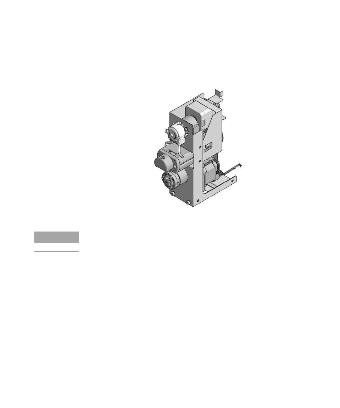
Hydraulic Box 24
Transport Assembly 26
Leak and Waste Handling 27
Leak Sensor 31
Waste Guidance 31
Waste Concept 32
This chapter gives an introduction to the module and instrument overview.
Agilent InfinityLab LC Series Vialsamplers User Manual 9
Page 10
1Introduction
Status indicator
Needle assembly
Drawer
Column shelf
Leak drain
Power switch
Product Description (G7129A)
Product Description (G7129A)
The Agilent 1260 Infinity II Vialsampler is an autosampler designed for the
reliability and ease-of-use needed for routine pharmaceutical tasks and quality
control, as well as for environmental and food analyses. It can house optionally
the integrated column compartment for two LC columns with temperature
control up to 80
4
°C to 40 °C, all within one module.
°C as well as a sample thermostat for stable temperatures from
Agilent InfinityLab LC Series Vialsamplers User Manual 10
Figure 1 Overview of the Vialsampler
Page 11

1Introduction
Features (G7129A)
Features (G7129A)
• High capacity – up to 132 vials (2 mL) or up to 36 vials (6 mL).
• Reliable injections – 0.1 to 100 µL injections for up to 600 bar (G7129A) and
up to 800
• Easy volume extensions – for injection volumes up to 1800 µL for applications
ranging from microbore to semipreparative chromatography.
•Lowest carryover – with an in needle flush port included, for rinsing the outside
of the needle.
• Efficient temperature control – with an integrated column compartment as
option or upgrade available. Which holds two columns up to 30
and provides heating capacity from 5
reproducible chromatography data at optimized resolution.
• Integrated sample thermostat – available as option or upgrade, providing
cooling and heating in the range from 4
• Low internal volume – for minimum contribution to a system's total internal
volume, which can be even further reduced using "bypass" mode.
•Increased productivity – with overlapped injections.
• Customizable injection program – available for customizing advanced
injections as well as for sample preparation steps upfront injection.
bar (G7129C).
cm length,
°C above ambient up to 80 °C for
°C - 40 °C.
Agilent InfinityLab LC Series Vialsamplers User Manual 11
Page 12
1Introduction
Status indicator
Needle assembly
Drawer
Column shelf
Leak drain
Power switch
Product Description (G7129B)
Product Description (G7129B)
The Agilent 1290 Infinity II Vialsampler (G7129B) is an autosampler designed for
UHPLC applications up to 1300
ease-of-use needed for routine pharmaceutical tasks and quality control, as well
as for environmental and food analyses. It can house optionally the integrated
column compartment for two LC columns with temperature control up to 80
as well as a sample thermostat for stable temperatures from 4
within one module.
bar. It provides the reliability, safety, and
°C
°C to 40 °C, all
Agilent InfinityLab LC Series Vialsamplers User Manual 12
Figure 2 Overview of the Vialsampler
Page 13

1Introduction
Features (G7129B)
Features (G7129B)
• Accurate and precise injections - within a wide and flexible range of volumes
• High capacity - up to 132 vials (2 mL) or up to 36 vials (6 mL).
• Easy volume extensions - for injection volumes up to 1500 µL for applications
ranging from microbore to semipreparative chromatography.
•Lowest carryover - with an in needle flush port included, for rinsing the outside
of the needle.
• Efficient temperature control - with an integrated column compartment as
option or upgrade available. Which holds two columns up to 30
and provides heating capacity from 5
reproducible chromatography data at optimized resolution.
• Integrated sample thermostat - available as option or upgrade, providing
cooling and heating in the range from 4
• Low internal volume - for minimum contribution to a system's total internal
volume, which can be even further reduced using bypass mode.
•Increased productivity - with overlapped injections.
• Customizable Injection program - available for customizing advanced
injections as well as for sample preparation steps upfront injection.
°C above ambient up to 80 °C for
– 40 °C.
cm length,
Agilent InfinityLab LC Series Vialsamplers User Manual 13
Page 14

1Introduction
Status indicator
Needle assembly
Drawer
Column shelf
Leak drain
Power switch
Product Description (G7129C)
Product Description (G7129C)
The Agilent 1260 Infinity II Vialsampler is an autosampler designed for the
reliability and ease-of-use needed for routine pharmaceutical tasks and quality
control, as well as for environmental and food analyses. It can house optionally
the integrated column compartment for two LC columns with temperature
control up to 80
4
°C to 40 °C, all within one module.
°C as well as a sample thermostat for stable temperatures from
Agilent InfinityLab LC Series Vialsamplers User Manual 14
Figure 3 Overview of the Vialsampler
Page 15

1Introduction
Features (G7129C)
Features (G7129C)
• High capacity – up to 132 vials (2 mL) or up to 36 vials (6 mL).
• Reliable injections – 0.1 to 100 µL injections for up to 600 bar (G7129A) and
up to 800
• Easy volume extensions – for injection volumes up to 1800 µL for applications
ranging from microbore to semipreparative chromatography.
•Lowest carryover – with an in needle flush port included, for rinsing the outside
of the needle.
• Efficient temperature control – with an integrated column compartment as
option or upgrade available. Which holds two columns up to 30
and provides heating capacity from 5
reproducible chromatography data at optimized resolution.
• Integrated sample thermostat – available as option or upgrade, providing
cooling and heating in the range from 4
• Low internal volume – for minimum contribution to a system's total internal
volume, which can be even further reduced using "bypass" mode.
•Increased productivity – with overlapped injections.
• Customizable injection program – available for customizing advanced
injections as well as for sample preparation steps upfront injection.
bar (G7129C).
cm length,
°C above ambient up to 80 °C for
°C - 40 °C.
Agilent InfinityLab LC Series Vialsamplers User Manual 15
Page 16

1Introduction
Overview of the Module
Overview of the Module
The Agilent InfinityLab LC Series Vialsampler is designed for use with other
modules of the Agilent InfinityLab LC Series, 1200 Series, and 1100 Series LC, as
well as with other LC systems with adequate remote-control capabilities. The
Vialsampler can be controlled from any computer with a suitable
chromatography data system (for example, Agilent OpenLab CDS, MassHunter,
etc.) or via an Agilent local control module (InfinityLab Companion or 1200
Infinity Series Instant Pilot).
The 1290 Infinity II Vialsampler (G7129B) can be operated at up to 1300 bar. The
two 1260 Infinity II Vialsampler variants (G7129A and G7129C) are limited to a
maximum system pressure of 600 and 800
The Vialsampler can accommodate two vial drawers, providing space for up to
132 samples. The two cartesian vial drawers allow for the use of either 66 × 2
or 18 × 6
system is also available, each capable of hosting 50 × 2
drawers are designed to ease method transfer from older Agilent samplers. The
Vialsampler can also be equipped with an external tray, which can be beneficial
for automation. The Agilent WalkUp solution fully supports the external tray.
mL vials. A pair of classic vial drawers with a numerical vial assignment
bar, respectively.
mL vials. The classic vial
mL
The Vialsampler features a robotic gripper arm for the transport of vials, driven by
four stepper motors to ensure the highest precision and flexibility for the
transport movement.
The default configuration of the analytical head and sample loop allows an
injection range from 0.1
0.1
– 100 μL for the 1260 Infinity II Vialsamplers. An analytical head with
extended volume is also available for injection volumes from 0.1
can be operated at up to 400
volume can even reach 1800
The 2-position/6-port injection valve is driven by a high-speed, hybrid stepper
motor, ensuring smooth switching between the mainpass and bypass positions.
Thanks to the flow-through design of the Vialsampler, the eluent continuously
rinses the component parts of the sample introduction system. This, together
with the automated needle wash function for rinsing the outer surface of the
needle, ensures the lowest level of carryover for each analysis. For advanced
delay volume reduction, the injection valve can be programmed to automatically
switch back to the bypass position when the injection is completed.
Agilent InfinityLab LC Series Vialsamplers User Manual 16
– 20 μL for the 1290 Infinity II Vialsampler and
– 900 μL, and
bar. With the Multidraw Kit, the maximum injection
μL.
Page 17

1Introduction
Overview of the Module
The Agilent InfinityLab Integrated Column Compartment, an optional upgrade for
the Vialsampler, eliminates the need for having a standalone column thermostat
in the LC stack. It has the heating capability of reaching temperatures up to 80
and can hold a total of two columns with maximum lengths of 30
For applications requiring control over the vial temperature, the Vialsampler can
be equipped with the Agilent InfinityLab Sample Thermostat (G7167-60101). It
features a vapor-compression refrigeration system and an electric heater,
allowing the Vialsampler to reach vial temperatures down to 4
cm.
°C and up to 40 °C.
°C
Agilent InfinityLab LC Series Vialsamplers User Manual 17
Page 18

1Introduction
Operating Principle
Operating Principle
Sampling Sequence
The Vialsampler processor continuously monitors the movements of the
vialsampler components during the sampling sequence. The processor defines
specific time windows and mechanical ranges for each movement. If a specific
step of the sampling sequence can’t be completed successfully, an error
message is generated.
During the sampling sequence, the solvent bypasses the vialsampler via the
injection valve. The gripper arm selects the sample vial, either from a static
sample rack, or from external vial positions. The gripper arm places the sample
vial below the injection needle. The required volume of sample is drawn into the
sample loop by the metering device. Sample is applied to the column when the
injection valve returns to the mainpass (main path) position at the end of the
sampling sequence.
The sampling sequence occurs in the following order:
1 The injection valve switches to the bypass position.
2 The piston of the metering device moves to the initialization position.
3 The gripper arm moves from the home position, and selects the vial. At the
same time, the needle lifts out of the seat.
4 The gripper moves into the needle station and stops in the draw position.
5 The needle lowers into the vial.
6 The metering device draws the defined sample volume.
7 The needle lifts out of the vial.
1
8 The gripper arm moves out slightly and stops in the wash position1.
9 The needle moves downwards and dips into the wash well of the wash port.
Simultaneously the peristaltic pump delivers the flush solvent.
10 The needle moves back.
11 The gripper arm moves out of the needle station and the wash port snaps
back in position.
1
only if automated needle wash is selected. If this feature is disabled, the gripper arm
positions the sample vial directly below the needle (Step 4) and lowers the needle into
the vial.
Agilent InfinityLab LC Series Vialsamplers User Manual 18
1
1
Page 19
1Introduction
Vial
Wash
port
Needle
seat
Sampling loop
Solvent
Wash
pump
Metering
device
Operating Principle
12 The gripper arm replaces the vial, and returns to the home position.
Simultaneously, the needle lowers into the seat.
13 The injection valve switches to the mainpass (main path) position.
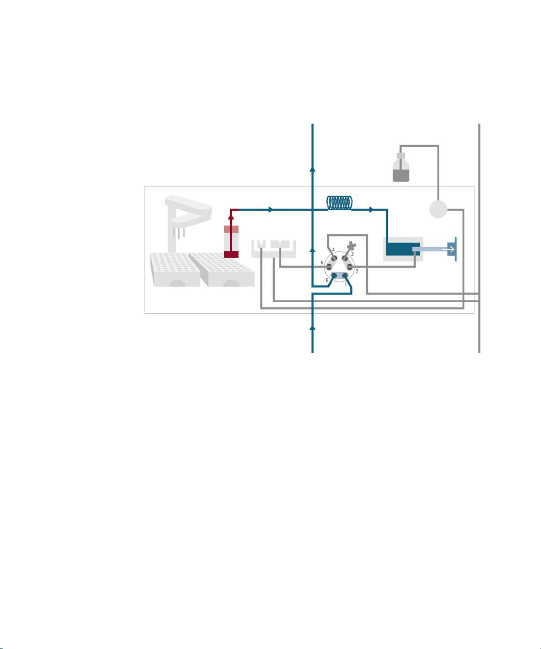
Injection Sequence
Before the start of the injection sequence, and during an analysis, the injection
valve is in the mainpass (main path) position (see
position, the mobile phase flows through the autosamplers metering device,
sample loop, and needle. This ensures that all parts in contact with sample are
flushed during the run, thus minimizing carryover.
Figure 4 on page 19). In this
Figure 4 Mainpass (main path) Position - standard position during runs and when the sampler
idle
is
Agilent InfinityLab LC Series Vialsamplers User Manual 19
Page 20
1Introduction
Vial
Wash
port
Needle
seat
Sampling loop
Solvent
Wash
pump
Metering
device
Operating Principle
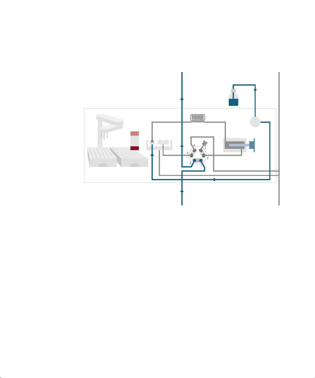
When the sample sequence begins, the valve unit switches to the bypass
position (see
Figure 5 on page 20). Solvent from the pump enters the valve unit at
port 1, and flows directly to the column through port 6.
Figure 5Valve in bypass - needle in vial, metering device aspirates sample volume
Agilent InfinityLab LC Series Vialsamplers User Manual 20
Page 21
1Introduction
Vial
Wash
port
Needle
seat
Sampling loop
Solvent
Wash
pump
Metering
device
Operating Principle
Then the vial is positioned below the needle. The needle moves down into the
vial, the metering unit draws the required sample volume into the loop, and the
needle is raised. In the next step, the needle is washed (see
Figure 6 on page 21).
Figure 6 Outer face of needle getting washed in wash port
Agilent InfinityLab LC Series Vialsamplers User Manual 21
Page 22
1Introduction
Vial
Wash
port
Needle
seat
Sampling loop
Solvent
Wash
pump
Metering
device
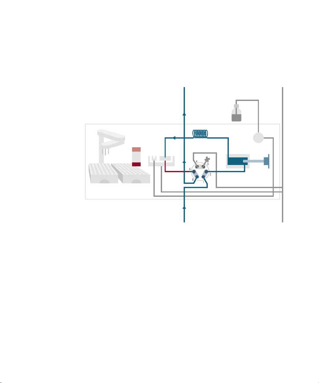
Operating Principle
When the metering unit has drawn the required volume of sample into the
sample loop, the vial is replaced in the sample tray. The wash port flips into the
origin position, the needle is lowered into the needle seat, and the injection valve
switches back to mainpass (main path) position, flushing the sample onto the
column (see
Figure 7 on page 22).
Figure 7 Valve switches to mainpass (main path) - sample is transferred towards the LC column
Agilent InfinityLab LC Series Vialsamplers User Manual 22
Page 23
1Introduction
Operating Principle
Needle Parkstation
The needle parkstation comprises two main assemblies: needle drive and wash
port.
Figure 8Needle Station
Needle-Drive
The needle movement is driven by a stepper motor connected to the spindle
assembly by a toothed belt. The circular motion of the motor is converted to
linear motion by the drive nut on the spindle assembly. The upper and lower
needle positions are detected by reflection sensors on the needle station board,
while the needle-in-vial position is determined by counting the motor steps from
the upper needle-sensor position.
Agilent InfinityLab LC Series Vialsamplers User Manual 23
Page 24
1Introduction
NOTE
Operating Principle
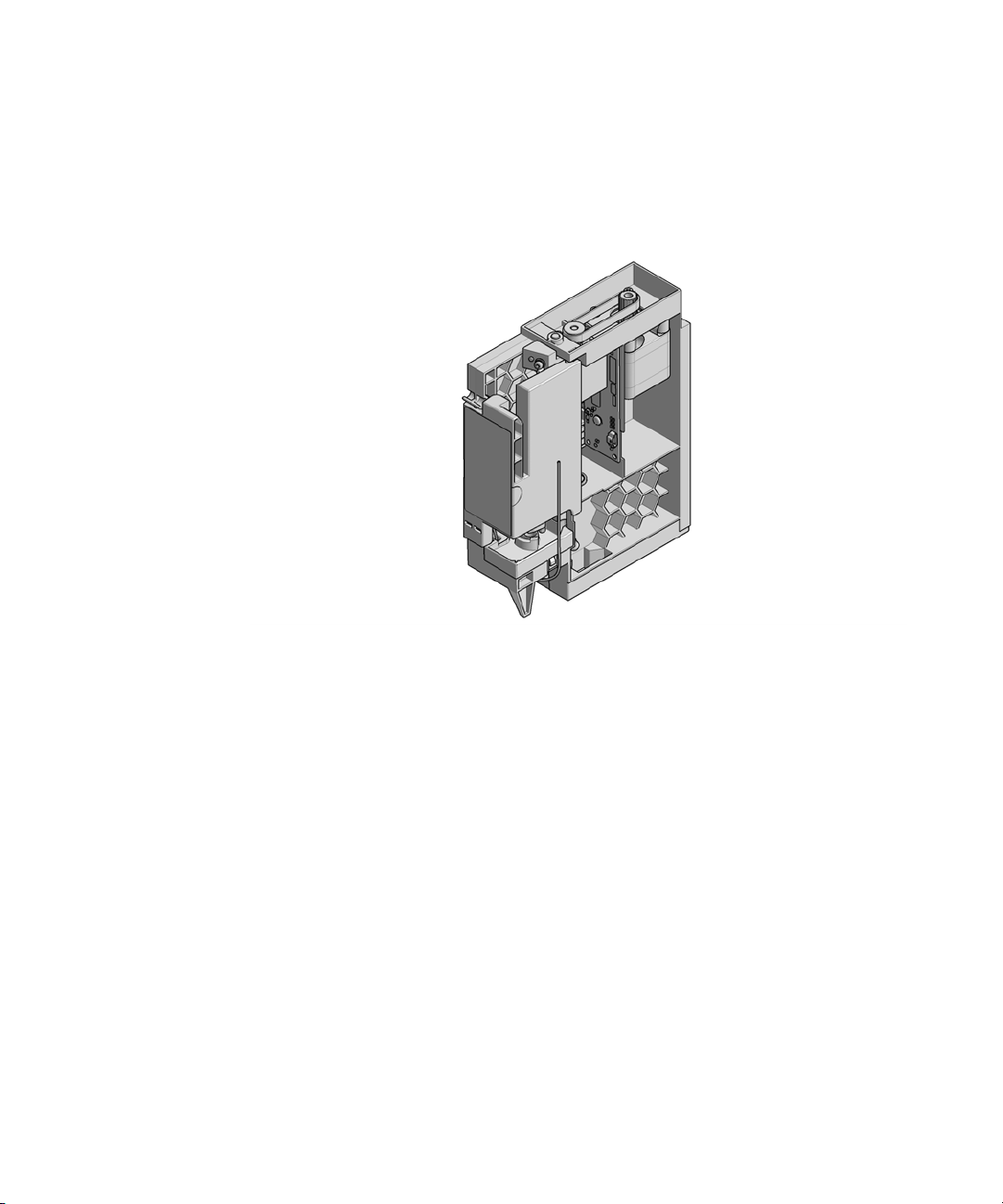
Hydraulic Box
The hydraulic box comprises two main assemblies: metering device, and
injection valve.
Figure 9 Hydraulic Unit
The replacement hydraulic box excludes the injection valve and metering head
assemblies.
Agilent InfinityLab LC Series Vialsamplers User Manual 24
Page 25

1Introduction
Operating Principle
Analytical Head
The analytical head is driven by the stepper motor that is connected to the drive
shaft by a toothed belt. The drive nut on the spindle converts the circular
movement of the spindle to linear motion. The drive nut pushes the sapphire
piston against the tension of the spring into the analytical head. The base of the
piston sits on the large bearing of the drive nut, which ensures the piston is
always centered. A ceramic ring guides the movement of the piston in the
analytical head. The home position of the piston is sensed by an optical sensor
on the hydraulic unit board while the sample volume is determined by counting
the number of steps from the home position. The backward movement of the
piston (driven by the spring) draws sample from the vial.
Injection Valve
The two-position 6-port injection valve is driven by a stepper motor. Only five of
the six ports are used (port 3 is not used). A lever/slider mechanism transfers the
movement of the stepper motor to the injection valve. Two microswitches
monitor switching of the valve (bypass and mainpass (main path) end positions).
No valve adjustments are required after replacing internal components.
Agilent InfinityLab LC Series Vialsamplers User Manual 25
Page 26
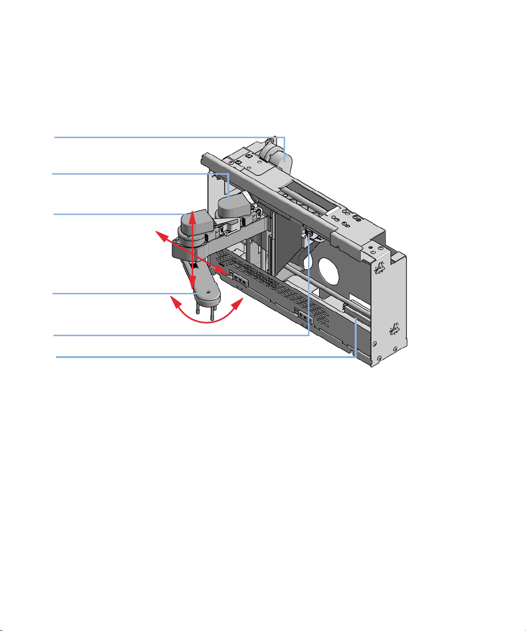
1Introduction
X motor
Theta motor
Gripper motor
Gripper arm
Z motor
Flex board
Theta axis
X axis
Z axis
Operating Principle
Transport Assembly
The transport unit comprises an X-axis slide (left-right motion), a Z-axis arm
(up-down motion), and a gripper assembly (rotation and vial-gripping).
Figure 10 Transport Assembly
The transport assembly uses four stepper motors driven in closed-loop mode for
accurate positioning of the gripper assembly. The rotational movement of the
motors is converted to linear motion (X- and Z-axes) by toothed belts connected
to the drive spindles. The rotation (theta axes) of the gripper assembly is
transferred from the motor by a toothed belt and series of gears. The opening
and closing of the gripper fingers are driven by a stepper motor linked by a
toothed belt to the planetary gearing inside the gripper assembly.
The stepper motor positions are determined by the optical encoders mounted
onto the stepper-motor housing. The encoders monitor the position of the
motors continually, and correct for position errors automatically (e.g. if the
gripper is accidentally moved out of position when loading vials into the vial tray).
The initialization positions of the moving components are sensed by reflection
sensors mounted on the flex board. These positions are used by the processor to
calculate the actual motor position. An additional six reflection sensors for tray
recognition are mounted on the flex board at the front of the assembly.
Agilent InfinityLab LC Series Vialsamplers User Manual 26
Page 27

1Introduction
Leak and Waste Handling
Leak and Waste Handling
The Agilent InfinityLab LC Series has been designed for safe leak and waste
handling. It is important that all security concepts are understood and
instructions are carefully followed.
The solvent cabinet is designed to store a maximum volume of 8 L solvent. The
maximum volume for an individual bottle stored in the solvent cabinet should not
exceed 2
Cabinets (a printed copy of the guideline has been shipped with the solvent
cabinet, electronic copies are available on the Internet).
All leak plane outlets are situated in a consistent position so that all Infinity and
Infinity II modules can be stacked on top of each other. Waste tubes are guided
through a channel on the right hand side of the instrument, keeping the front
access clear from tubes.
The leak plane provides leak management by catching all internal liquid leaks,
guiding them to the leak sensor for leak detection, and passing them on to the
next module below, if the leak sensor fails. The leak sensor in the leak plane
stops the running system as soon as the leak detection level is reached.
Solvent and condensate is guided through the waste channel into the waste
container:
• from the detector's flow cell outlet
• from the Multisampler needle wash port
• from the Sample Cooler or Sample Thermostat (condensate)
• from the pump's Seal Wash Sensor (if applicable)
• from the pump's Purge Valve or Multipurpose Valve
L. For details, see the usage guideline for the Agilent Infinity II Solvent
Agilent InfinityLab LC Series Vialsamplers User Manual 27
Page 28
1Introduction
Leak and Waste Handling
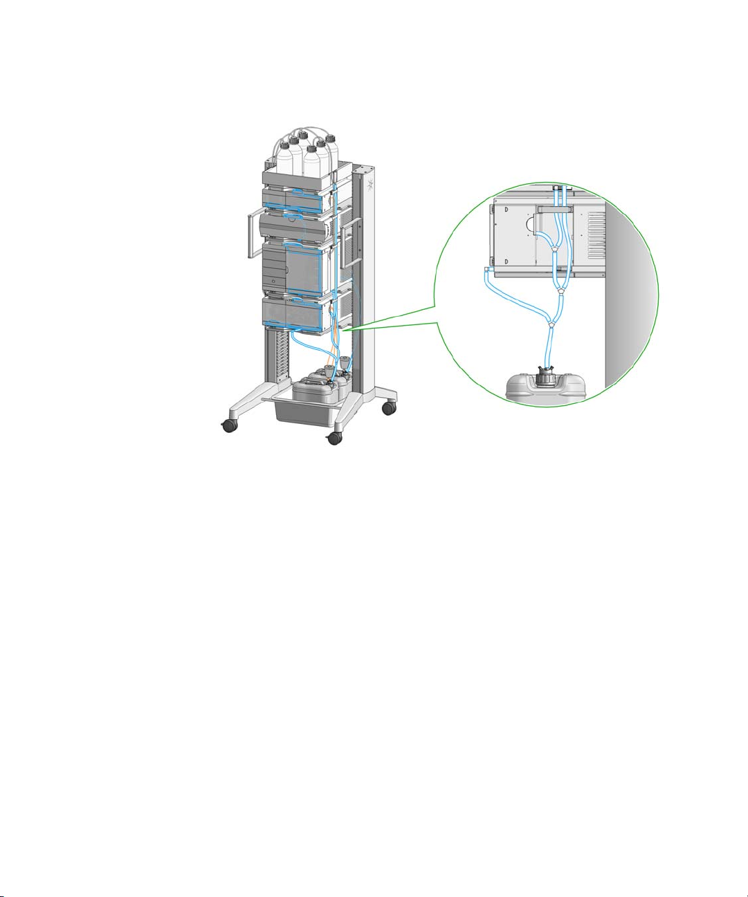
Figure 11 Infinity II Leak Waste Concept (Flex Bench installation)
Agilent InfinityLab LC Series Vialsamplers User Manual 28
Page 29
1Introduction
Leak and Waste Handling
Figure 12 Infinity II Single Stack Leak Waste Concept (bench installation)
Agilent InfinityLab LC Series Vialsamplers User Manual 29
Page 30
1Introduction
Leak and Waste Handling
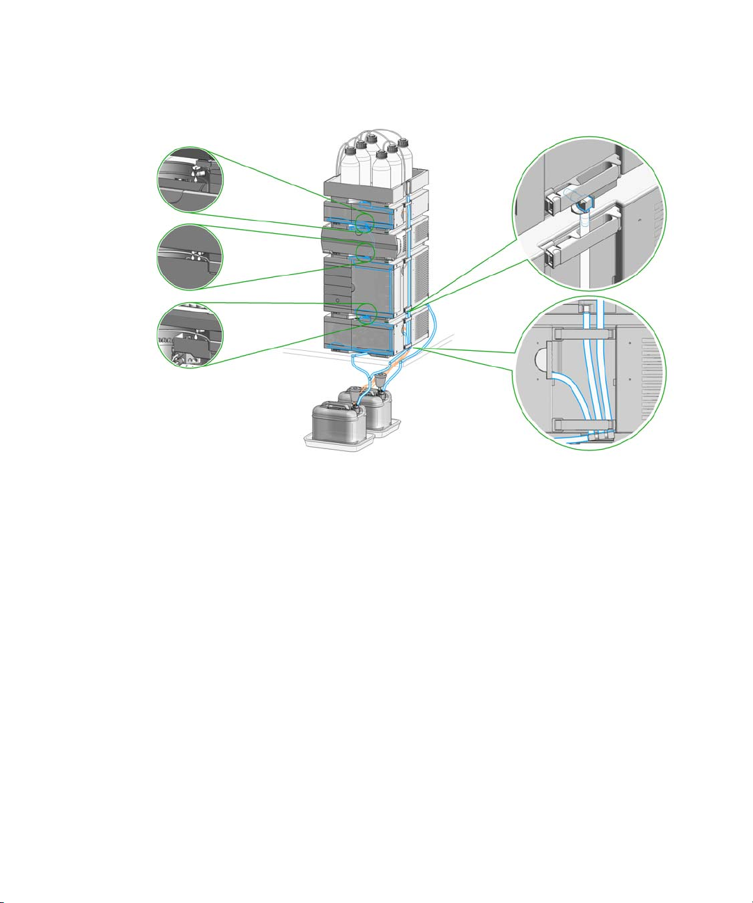
Figure 13 Infinity II Two Stack Leak Waste Concept (bench installation)
The waste tube connected to the leak plane outlet on each of the bottom
instruments guides the solvent to a suitable waste container.
Agilent InfinityLab LC Series Vialsamplers User Manual 30
Page 31

1Introduction
CAUTION
NOTE
NOTE
Leak and Waste Handling
Leak Sensor
Solvent incompatibility
The solvent DMF (dimethyl formamide) leads to corrosion of the leak sensor.
The material of the leak sensor, PVDF (polyvinylidene fluoride), is incompatible
with DMF.
Do not use DMF as mobile phase.
Check the leak sensor regularly for corrosion.
The leak sensor in the sampler is hidden under the ICC Column Heater or Column
Shelf respectively.
Waste Guidance
Agilent InfinityLab LC Series Vialsamplers User Manual 31
The waste drainage must go straight into the waste containers. The waste flow
must not be restricted at bends or joints.
Page 32

1Introduction
Leak and Waste Handling
Waste Concept
1 Agilent recommends using the 6 L waste can with 1 Stay Safe cap GL45 with
4 ports (5043-1221) for optimal and safe waste disposal. If you decide to use
your own waste solution, make sure that the tubes don't immerse in the liquid.
Agilent InfinityLab LC Series Vialsamplers User Manual 32
Page 33

2 Site Requirements and Specifications
Site Requirements 34
Physical Specifications 38
Performance Specifications 39
Performance Specifications (G7129A) 39
Performance Specifications (G7129B) 42
Performance Specifications (G7129C) 45
Specifications of the Sample Cooler 47
Specifications of the Sample Thermostat 49
Specifications of the Integrated Column Compartment 51
This chapter provides information on environmental requirements, physical and
performance specifications.
Agilent InfinityLab LC Series Vialsamplers User Manual 33
Page 34

2 Site Requirements and Specifications
WARNING
WARNING
WARNING
Site Requirements
Site Requirements
Site Requirements
A suitable environment is important to ensure optimum performance of the
instrument.
Power Considerations
The module power supply has wide ranging capability. It accepts any line voltage
in the range described in
selector in the rear of the module. There are also no externally accessible fuses,
because automatic electronic fuses are implemented in the power supply.
Hazard of electrical shock or damage of your instrumentation
can result, if the devices are connected to a line voltage higher than
specified.
Connect your instrument to the specified line voltage only.
Table 1 on page 38. Consequently there is no voltage
Agilent InfinityLab LC Series Vialsamplers User Manual 34
Electrical shock hazard
The module is partially energized when switched off, as long as the power
cord is plugged in.
The cover protects users from personal injuries, for example electrical
shock.
Do not open the cover.
Do not operate the instrument and disconnect the power cable in case
the cover has any signs of damage.
Contact Agilent for support and request an instrument repair service.
Inaccessible power plug.
In case of emergency it must be possible to disconnect the instrument
from the power line at any time.
Make sure the power connector of the instrument can be easily reached
and unplugged.
Provide sufficient space behind the power socket of the instrument to
unplug the cable.
Page 35

2 Site Requirements and Specifications
WARNING
WARNING
WARNING
Site Requirements
Power Cords
Country-specific power cords are available for the module. The female end of all
power cords is identical. It plugs into the power-input socket at the rear. The male
end of each power cord is different and designed to match the wall socket of a
particular country or region.
Agilent makes sure that your instrument is shipped with the power cord that is
suitable for your particular country or region.
Unintended use of power cords
Using power cords for unintended purposes can lead to personal injury or
damage of electronic equipment.
Never use a power cord other than the one that Agilent shipped with this
instrument.
Never use the power cords that Agilent Technologies supplies with this
instrument for any other equipment.
Never use cables other than the ones supplied by Agilent Technologies
to ensure proper functionality and compliance with safety or EMC
regulations.
Agilent InfinityLab LC Series Vialsamplers User Manual 35
Absence of ground connection
The absence of ground connection can lead to electric shock or short
circuit.
Never operate your instrumentation from a power outlet that has no
ground connection.
Electrical shock hazard
Solvents may damage electrical cables.
Prevent electrical cables from getting in contact with solvents.
Exchange electrical cables after contact with solvents.
Page 36

2 Site Requirements and Specifications
WARNING
NOTE
Site Requirements
Room Size and Ventilation
Flammable refrigerant
Formation of flammable gas-air mixtures inside the Sample Thermostat
and laboratory.
Keep open fire or sources of ignition away from the device.
Ensure a room size of 4 m3 (1 m3 for every 8 g of R600a refrigerant
inside of the Sample Thermostat).
Ensure adequate ventilation: typical air exchange of 25 m3/h per m2 of
laboratory floor area.
Keep all ventilation openings in the enclosure clear of obstructions. Do
not block the openings on the circumference of the Sample Thermostat.
Bench Space
Agilent InfinityLab LC Series Vialsamplers User Manual 36
The module dimensions and weight (see Table 1 on page 38) allow you to place
the module on almost any desk or laboratory bench. It needs an additional
2.5
cm (1.0 inches) of space on either side and approximately 8 cm (3.1 inches)
in the rear for air circulation and electric connections.
If the bench shall carry a complete HPLC system, make sure that the bench is
designed to bear the weight of all modules.
The module should be operated in a horizontal position, especially if a Sample
Cooler or Sample Thermostat is installed. Use a bubble level to check the leveling
of the sampler.
Agilent recommends that you install the HPLC instrument in the InfinityLab Flex
Bench rack. This option helps to save bench space as all modules can be placed
into one single stack. It also allows to easily relocate the instrument to another
laboratory.
Page 37

2 Site Requirements and Specifications
WARNING
CAUTION
Site Requirements
Heavy weight
The module is heavy.
Carry the module at least with 2 people.
Avoid back strain or injury by following all precautions for lifting heavy
objects.
Ensure that the load is as close to your body as possible.
Ensure that you can cope with the weight of your load.
Condensation
Condensation within the module
Condensation can damage the system electronics.
Do not store, ship or use your module under conditions where temperature
fluctuations could cause condensation within the module.
Agilent InfinityLab LC Series Vialsamplers User Manual 37
If your module was shipped in cold weather, leave it in its box and allow it to
warm slowly to room temperature to avoid condensation.
Page 38

2 Site Requirements and Specifications
Physical Specifications
Physical Specifications
Tab le 1 Physical Specifications G7129A, G7129B, G7129C
Type Specification Comments
Weight 19 kg (41.9 lbs) w/o sample thermostat
Dimensions
(height × width × depth)
Line voltage 100 – 240 V~, ± 10 % Wide-ranging capability
Line frequency 50 or 60 Hz, ± 5 %
Power consumption 350 VA, 350 W, 1195 BTU/h
Ambient operating temperature
320 x 396 x 468 mm
(12.8 x 15.6 x 18.4 inches)
4 - 40 °C (39 - 104 °F); without sample thermostat up to 55 °C (131 °F)
Ambient non-operating temperature
Humidity
Operating altitude Up to 3000 m (9842 ft)
Safety standards:
IEC, EN, CSA, UL
ISM Classification ISM Group 1 Class B According to CISPR 11
Permitted solvents Boiling point ≥56 °C (133 °F).
1
If a sample thermostat is included the upper value for humidity can be reduced. Please check your lab
conditions to stay beyond dew point values for non–condensing operation.
-40 – 70 °C (-40 – 158 °F)
< 95 % r.h. at 40 °C (104 °F)
Installation category II, Pollution degree 2 For indoor use only.
Auto-ignition temperature ≥200 °C
(394
°F).
1
Non-condensing
Agilent InfinityLab LC Series Vialsamplers User Manual 38
Page 39

2 Site Requirements and Specifications
Performance Specifications
Performance Specifications
Performance Specifications (G7129A)
Tab le 2 Performance Specifications G7129A
Type Specification Comments Method/Conditions
Injection range 0.1 – 100 µL in 0.1 µL incre-
ments with 100 µL up to
60
MPa
0.1 – 900 µL in 0.1 µL increments with 900 µL up to
40
MPa
Injection precision <0.25 % RSD of peak areas from
5
µL to 100 µL
Pressure range 0 – 60 MPa (0 – 600 bar,
– 8702 psi)
0
0 – 40 MPa (0 – 400 bar,
0
– 5801 psi)
Sample viscosity
range
Sample capacity 132 x 2 mL vial (two trays
0.2 – 5.0 cP
default)
100 x 2 mL vial (two classic
trays optional)
36 x 6 mL vials (two trays
optional)
Up to 1800 µL with multiple
draw (hardware modification
required)
Requires 900 µL analytical head
Measured caffeine
for 900 µL Analytical Head
Agilent InfinityLab LC Series Vialsamplers User Manual 39
Page 40

2 Site Requirements and Specifications
Performance Specifications
Table 2 Performance Specifications G7129A
Type Specification Comments Method/Conditions
Carryover <0.004 % (40 ppm) with needle
wash
Injection cycle time 18 s for draw speed 200 µL/min
Ejection speed: 200 µL/min
Injection volume: 1 µL
Minimum sample volume
1 µL from 5 µL sample in 100 µL
microvial, or 1
sample in 300
µL from 10 µL
µL microvial.
Needle height offset has to be
adapted to ensure that needle
doesn’t touch vial bottom.
Default needle height = 0
equates to 2
bottom.
mm above the vial
Using the following conditions:
• Column: Agilent Pursuit XRs
3 C18, 2.0 x 50
• Mobile Phase:
• A: 0.1 % TFA in water
• B: 0.1 % TFA in acetoni-
trile
• Isocratic : %B = 40 %
• Flow rate: 0.5 mL/min
• Temperature: Ambient
• Wavelength: 257/4 nm
• Injection volume: 1 µL
• Sample: 1200 ng/µL Chlor-
hexidine for UV (dissolved
with mobile phase A), 1
injected and measured with
Agilent UV detector
• Wash solution: H2O with
0.1
% TFA (3 s)
mm
µL
Instrument Control LC & CE Drivers A.02.12 or
above
Instrument Control Framework
(ICF) A.02.03 or above
Instant Pilot (G4208A) with firmware B.02.19 or above
Lab Advisor B.02.07 or above
Communication Controller Area Network
(CAN),Local Area Network
(LAN)
ERI: ready, start, stop and
shut-down signals
For details about supported
software versions refer to the
compatibility matrix of your ver
sion of the LC & CE Drivers
-
Agilent InfinityLab LC Series Vialsamplers User Manual 40
Page 41

2 Site Requirements and Specifications
Performance Specifications
Table 2 Performance Specifications G7129A
Type Specification Comments Method/Conditions
Maintenance and
safety-related features
GLP features Early maintenance feedback
Housing All materials recyclable.
Extensive diagnostics, error
detection and display with Agi
lent Lab Advisor software
Leak detection, safe leak handling, leak output signal for
shutdown of pumping system,
and low voltages in major main
tenance areas
(EMF) for continuous tracking
of instrument usage with
user-settable limits and feed
back messages. Electronic
records of maintenance and
errors.
-
-
-
Agilent InfinityLab LC Series Vialsamplers User Manual 41
Page 42

2 Site Requirements and Specifications
Performance Specifications
Performance Specifications (G7129B)
Tab le 3 Performance Specifications G7129B
Type Specification Comments Method/Conditions
Injection range 0.1 – 20 µL in 0.1 µL increments
(default)
0.1 – 40 µL in 0.1 µL increments
µL loop is installed)
(if 40
0.1 – 120 µL in 0.1 µL incre-
ments with 1290 Infinity large
volume injection kit (hardware
modification required)
0.1 – 100 µL in 0.1 µL (if 100 µL
loop and 100
installed)
Injection precision <0.25 % RSD of peak areas from
µL to 100 µL
5
Pressure range Up to 130 MPa (1300 bar,
18854
Sample viscosity
range
Sample capacity 132 x 2 mL vial (two trays
0.2 – 5.0 cP
default)
100 x 2 mL vial (two classic
trays optional)
36 x 6 mL vials (two trays
optional)
µL head is
psi)
Up to 1500 µL (with 1400 µL
multi-draw kit and 100
lytical head)
up to 130 MPa (1300 bar,
18854
psi)
up to 60 MPa (600 bar,
psi)
8702
Measured caffeine
µL ana-
Agilent InfinityLab LC Series Vialsamplers User Manual 42
Page 43

2 Site Requirements and Specifications
Performance Specifications
Table 3 Performance Specifications G7129B
Type Specification Comments Method/Conditions
Carryover <0.004 % (40 ppm) with needle
wash
Injection cycle time 18 s for draw speed 200 µL/min
Ejection speed: 200 µL/min
Injection volume: 1 µL
Minimum sample volume
1 µL from 5 µL sample in 100 µL
microvial, or 1
sample in 300
µL from 10 µL
µL microvial.
Needle height offset has to be
adapted to ensure that needle
doesn’t touch vial bottom.
Default needle height = 0
equates to 2
bottom.
mm above the vial
Using the following conditions:
• Column: Agilent Pursuit XRs
3 C18, 2.0 x 50
• Mobile Phase:
• A: 0.1 % TFA in water
• B: 0.1 % TFA in acetoni-
trile
• Isocratic : %B = 40 %
• Flow rate: 0.5 mL/min
• Temperature: Ambient
• Wavelength: 257/4 nm
• Injection volume: 1 µL
• Sample: 1200 ng/µL Chlor-
hexidine for UV (dissolved
with mobile phase A), 1
injected and measured with
Agilent UV detector
• Wash solution: H2O with
0.1
% TFA (3 s)
mm
µL
Instrument control LC & CE Drivers A.02.12 or
above
Instrument Control Framework
(ICF) A.02.03 or above
Instant Pilot (G4208A) with firmware B.02.19 or above
Lab Advisor B.02.07 or above
Communication Controller Area Network (CAN),
Local Area Network (LAN),
ERI: ready, start, stop and
shut-down signals
For details about supported
software versions refer to the
compatibility matrix of your ver
sion of the LC & CE Drivers
-
Agilent InfinityLab LC Series Vialsamplers User Manual 43
Page 44

2 Site Requirements and Specifications
Performance Specifications
Table 3 Performance Specifications G7129B
Type Specification Comments Method/Conditions
Maintenance and
safety-related features
GLP features Early maintenance feedback
Housing All materials recyclable.
Extensive diagnostics, error
detection and display with Agi
lent Lab Advisor software
Leak detection, safe leak handling, leak output signal for
shutdown of pumping system,
and low voltages in major main
tenance areas
(EMF) for continuous tracking
of instrument usage with
user-settable limits and feed
back messages. Electronic
records of maintenance and
errors.
-
-
-
Agilent InfinityLab LC Series Vialsamplers User Manual 44
Page 45

2 Site Requirements and Specifications
Performance Specifications
Performance Specifications (G7129C)
Tab le 4 Performance Specifications G7129C
Type Specification Comments Method/Conditions
Injection range 0.1 – 100 µL in 0.1 µL incre-
ments with 100 µL up to
80
MPa
Injection precision <0.25 % RSD of peak areas from
5
µL to 100 µL
Pressure range 0 – 80 MPa (0 – 800 bar,
– 11603 psi)
0
Sample viscosity
range
Sample capacity 132 x 2 mL vial (two trays
Carryover <0.004 % (40 ppm) with needle
0.2 – 5.0 cP
default)
100 x 2 mL vial (two classic
trays optional)
36 x 6 mL vials (two trays
optional)
wash
Up to 1800 µL with multiple
draw (hardware modification
required)
Measured caffeine
Using the following conditions:
• Column: Agilent Pursuit XRs
3 C18, 2.0 x 50
• Mobile Phase:
• A: 0.1 % TFA in water
• B: 0.1 % TFA in acetoni-
trile
• Isocratic : %B = 40 %
• Flow rate: 0.5 mL/min
• Temperature: Ambient
• Wavelength: 257/4 nm
• Injection volume: 1 µL
• Sample: 1200 ng/µL Chlor-
hexidine for UV (dissolved
with mobile phase A), 1
injected and measured with
Agilent UV detector
• Wash solution: H2O with
0.1
% TFA (3 s)
mm
µL
Injection cycle time 18 s for draw speed 200 µL/min
Ejection speed: 200 µL/min
Injection volume: 1 µL
Agilent InfinityLab LC Series Vialsamplers User Manual 45
Page 46

2 Site Requirements and Specifications
Performance Specifications
Table 4 Performance Specifications G7129C
Type Specification Comments Method/Conditions
Minimum sample volume
Instrument Control LC & CE Drivers A.02.17 or
Communication Controller Area Network (CAN),
Maintenance and
safety-related features
1 µL from 5 µL sample in 100 µL
microvial, or 1
sample in 300
above
Instrument Control Framework
(ICF) A.02.05 or above
Instant Pilot (G4208A) with firmware B.02.22 or above
InfinityLab LC Companion
(G7108A)
Lab Advisor B.02.10 or above
Local Area Network (LAN),
ERI: ready, start, stop and
shut-down signals
Extensive diagnostics, error
detection and display with Agi
lent Lab Advisor software
Leak detection, safe leak handling, leak output signal for
shutdown of pumping system,
and low voltages in major main
tenance areas
µL from 10 µL
µL microvial.
Needle height offset has to be
adapted to ensure that needle
doesn’t touch vial bottom.
Default needle height = 0
equates to 2
bottom.
For details about supported
software versions refer to the
compatibility matrix of your ver
sion of the LC & CE Drivers
-
-
mm above the vial
-
GLP features Early maintenance feedback
(EMF) for continuous tracking
of instrument usage with
user-settable limits and feed
back messages. Electronic
records of maintenance and
errors.
Housing All materials recyclable.
-
Agilent InfinityLab LC Series Vialsamplers User Manual 46
Page 47

2 Site Requirements and Specifications
Specifications of the Sample Cooler
Specifications of the Sample Cooler
The Agilent Infinity II Sample Cooler is a vapor-compression refrigeration system
that uses a fluorinated greenhouse gas (HCF-134a) as the refrigerant. For
information on carbon dioxide equivalency (CDE) and global warming potential
(GWP), see the instrument label.
Tab le 5 Physical Specification of the Sample Cooler
Type Specification Comment
Weight < 6 kg (< 13.2 lbs)
Dimensions (height × width × depth) 205 x 340 x 370 mm
(8.1 x 13.4 x 14.6 inches)
Refrigerant gas HFC-134a (0.042 kg) Ozone depletion poten-
tial (ODP) = 0
Supply voltage 24 VDC
Current 10 A max.
Ambient operating temperature 4 – 40 ° C (39 – 104 ° F)
Ambient non-operating temperature -40 – 70 ° C (-40 – 158 ° F)
Humidity < 95 % r.h. at 40 °C (104 °F) Non-condensing
Operating altitude Up to 3000 m (9842 ft)
Safety standards:
IEC, EN, CSA, UL
ISM Classification ISM Group 1 Class B According to CISPR 11
Installation category II, Pollution
degree 2
For indoor use only
Agilent InfinityLab LC Series Vialsamplers User Manual 47
Page 48

2 Site Requirements and Specifications
CAUTION
NOTE
Specifications of the Sample Cooler
General hazards and improper disposal
Improper disposal of the media and components used pollutes the
environment.
The disposal or scrapping of the Sample Cooler or the Sample Thermostat
must be carried out by a qualified disposal company.
All media must be disposed of in accordance with national and local
regulations.
Please contact your local Agilent Service Center in regard to safe
environmental disposal of the appliance or check www.agilent.com for
more info.
Tab le 6 Performance Specifications of the Sample Cooler
Type Specifications
Operating principle High performance, low-energy consumption
micro-compressor based cooler with
ozone-friendly HFC-134a coolant (42 g),
user-upgradable.
Agilent InfinityLab LC Series Vialsamplers User Manual 48
Temperature range from 4 °C to 5 °C below ambient
Temperature settable from 4 – 40 °C in 1 ° increments
Temperature accuracy (<25 °C, <50 % r.H.) 2 °C to 6 °C at a setpoint of 4 °C
The Agilent Infinity II Sample Cooler is not available for trade sales anymore and
has been replaced by the Agilent InfinityLab Sample Thermostat.
Page 49

2 Site Requirements and Specifications
Specifications of the Sample Thermostat
Specifications of the Sample Thermostat
The Agilent InfinityLab Sample Thermostat is the combination of an electric
heater and a vapor-compression refrigeration system. It uses isobutane as a
non-Freon refrigerant, which is harmless to the environment and does not affect
the ozone layer and global warming but is combustible. Please adhere to the
warnings listed in the manual.
Tab le 7 Physical Specifications of the Sample Thermostat
Type Specification Comments
Weight <6 kg (< 13.2 lbs)
Dimensions
(height x width x depth)
Refrigerant gas R600a (0.030 kg) Ozone depletion potential (ODP) =0
Supply voltage 24VDC
205 x 340 x 370 mm
(8.1 x 13.4 x 14.6 inches)
Global warming potential (GWP) =3
Current 10 A max.
Ambient operating
temperature
Ambient non-operating temperature
Humidity < 95 % r.h. at 40 °C (104 °F) Non-condensing
Operating altitude Up to 3000 m (9842 ft)
Safety standards:
IEC, EN, CSA, UL
ISM Classification ISM Group 1 Class B According to CISPR 11
4 – 40 °C (39 – 104 °F)
-40 – 70 °C (-40 – 158 °F)
Installation category II,
Pollution degree 2
For indoor use only
Agilent InfinityLab LC Series Vialsamplers User Manual 49
Page 50

2 Site Requirements and Specifications
CAUTION
NOTE
Specifications of the Sample Thermostat
General hazards and improper disposal
Improper disposal of the media and components used pollutes the
environment.
The disposal or scrapping of the Sample Cooler or the Sample Thermostat
must be carried out by a qualified disposal company.
All media must be disposed of in accordance with national and local
regulations.
Please contact your local Agilent Service Center in regard to safe
environmental disposal of the appliance or check www.agilent.com for
more info.
Tab le 8 Performance Specifications for the Sample Thermostat
Type Specifications
Operating principle High performance, low-energy consumption micro-compressor based
cooler with natural R600a coolant (Butane 30
Temperature range from 4 – 40 °C
Temperature settable from 4 – 40 °C in 1 ° increments
g), user-upgradable
Agilent InfinityLab LC Series Vialsamplers User Manual 50
Temperature accuracy
(<25 °C, <50 % r.H.)
2 °C to 6 °C at a setpoint of 4 °C
Minimum firmware revision for the Sample Thermostat is D.07.22.
Minimum LC driver revision for the Sample Thermostat is A.02.14.
Page 51

2 Site Requirements and Specifications
Specifications of the Integrated Column Compartment
Specifications of the Integrated Column
Compartment
Physical Specifications Agilent InfinityLab LC Series Integrated Column Compartment (G7130A)
Tab le 9 Physical Specifications (G7130A)
Type Specification Comment
Weight 1.8 kg (4.0 lbs)
Dimensions
(height x width x depth)
Supply Voltage 24 V DC
Power consumption 110 W
Ambient operating temperature 4 – 55 °C (39 – 131 °F)
Ambient non-operating temperature
Humidity
Operating altitude Up to 3000 m (9842 ft)
Safety standards
IEC, EN, CSA, UL
ISM Classification ISM Group 1 Class B According to CISPR 11
1
If a sample cooler is included the upper value for humidity can be reduced. Please check your lab conditions to stay beyond dew point values for non–condensing operation.
86.5 x 396.0 x 106.5 mm
(3.4 x 15.6 x 4.2 inches)
-40 – 70 °C (-40 – 158 °F)
< 95 % r.h. at 40 °C (104 °F)
Installation category II, Pollution
degree 2
1
Maximum outside
Non-condensing
For indoor use only
Agilent InfinityLab LC Series Vialsamplers User Manual 51
Page 52

2 Site Requirements and Specifications
Specifications of the Integrated Column Compartment
Performance Specifications Agilent InfinityLab LC Series Integrated Column Compartment (G7130A)
Tab le 10 Performance Specifications G7130A
Type Specification Comments
Temperature range 5 °C above ambient to 80 °C
Column capacity 2 columns up to 30 cm and
mm ID
4.6
Temperature stability ±0.10 °C at sensor
Temperature accuracy ±0.8 K (±0.5 K with calibration)
Warm up time 20 – 40 °C in 5 min at sensor
Agilent InfinityLab LC Series Vialsamplers User Manual 52
Page 53

3Using the Module
Magnets 55
Turn on/off 56
Status Indicators 58
Vial Drawers and Trays 59
List of Drawers and Trays 59
Exchange Drawers 62
Insert a Vial Into the Sampler 65
Install the External Tray 67
Choice of Vials and Caps 70
Compatible Vials and Caps for the 2 mL Vial Drawers 70
Compatible Vials and Caps for the 6 mL Vial Drawer 73
Install the Optional Integrated Column Compartment 74
Unpacking the Unit 74
Install the Integrated Column Compartment 76
Install a Column in the ICC 82
Remove a Column from the ICC 86
Install the Column Shelf 88
Install the Column ID Upgrade Kit 92
Connect a Column Identification Tag to the Tag Reader 94
Using the Optional Integrated Column Compartment 96
Dashboard 96
Control Interface 97
Control 98
Method Parameters 99
Online Signals 101
Column Assignment 102
Column Tag Information Table 103
Using Column Identification Tags 104
Install the Optional Sample Cooler/Sample Thermostat 116
Unpacking the Unit 116
Install the Sample Cooler/Sample Thermostat 117
Using the Optional Sample Cooler/Sample Thermostat 123
Dashboard 123
Control Interface 124
Control 125
Temperature Mode 127
Online Signals 128
Agilent InfinityLab LC Series Vialsamplers User Manual 53
Page 54

3Using the Module
Specifications of the Integrated Column Compartment
Reporting Sample Temperature 129
Operation Information 130
Transporting the Sampler 132
Prepare a Sampler Without Cooler/Thermostat for Transportation 132
Prepare a Sampler with Cooler/Thermostat for Transportation 133
Install the Transport Protection Foam 135
Agilent Local Control Modules 137
This chapter provides information on how to use the module.
Agilent InfinityLab LC Series Vialsamplers User Manual 54
Page 55

3Using the Module
Magnets
Magnets
1 Magnets in doors of pumps, autosamplers, detectors, and fraction collectors.
Agilent InfinityLab LC Series Vialsamplers User Manual 55
Page 56

3Using the Module
Turn on/off
Turn on/off
This procedure exemplarily shows an arbitrary LC stack configuration.
1 2
Power switch: On
Agilent InfinityLab LC Series Vialsamplers User Manual 56
Page 57

3Using the Module
Turn on/off
3 Turn instrument On/Off with the control software. 4
Power switch: Off
5
Agilent InfinityLab LC Series Vialsamplers User Manual 57
Page 58

3Using the Module
Status Indicators
Status Indicators
This procedure exemplarily shows an arbitrary LC stack configuration.
1 The module status indicator indicates one of six possible module conditions:
Status indicators
1. Idle
2. Run mode
3. Not-ready. Waiting for a specific pre-run condition to be reached or
completed.
4. Error mode - interrupts the analysis and requires attention (for example a
leak or defective internal components).
5. Resident mode (blinking) - for example during update of main firmware.
6. Bootloader mode (fast blinking). Try to re-boot the module or try a
cold-start. Then try a firmware update.
Agilent InfinityLab LC Series Vialsamplers User Manual 58
Page 59

3Using the Module
NOTE
Vial Drawers and Trays
Vial Drawers and Trays
List of Drawers and Trays
Supported drawers for the module:
p/n Description
G7129-60010 Drawer for 66 x 2 mL Vials
G7129-60110 Drawer for 18 x 6 mL Vials
G7129-68210 Classic Vial Drawer Kit
G7129-60210 Classic Drawer for 50 x 2 mL Vials, Left
G7129-60220 Classic Drawer for 50 x 2 mL Vials, Right
G7129-60000 External Tray for 5 x 2 mL Vials
Install all drawers for best cooling performance.
Drawer Combinations
Drawers can be installed in any combination enabling both 2 mL- and 6 mL-vials
to be used simultaneously. The only exception is the usage of the classical
drawer option (100 x 2
mL). This option can't combine with the other drawers.
Numbering of Vial Positions
The standard 2*66 vial drawers have 132 vial positions from P1-A1-P2-F11.
However, when using two drawers, the numbering convention is slightly different.
The vial positions of the right-hand drawer begin at position P2-A1 as follows:
Left-hand Drawer for 66 x 2 mL Vials: P1-A1 to P1-F11
Left-hand Drawer for 18 x 6 mL Vials: P1-A1 to P1-C6
Right-hand Drawer for 66 x 2 mL Vials: P2-A1 to P2-F11
Right-hand Drawer for 18 x 6 mL Vials: P2-A1 to P2-C6
Drawer for 50 x 2 mL Vials Classic Left: Vial 1-50
Agilent InfinityLab LC Series Vialsamplers User Manual 59
Page 60

3Using the Module
P1-A1
P1-F11
P2-A1
P2-F11
P1-A1
P1-C6
P2-A1
P2-C6
Vial Drawers and Trays
Drawer for 50 x 2 mL Vials Classic Right: Vial 51-100
External Tray 5-position: 201 – 205 Position
(The disposal tube is installed into the external tray by turning and pushing it into
the backside of the hole position, No. 206)
Figure 14 Numbering of drawer position (left-hand Drawer for 66 x 2 mL Vials)
Figure 15 Numbering of drawer position (right-hand Drawer for 66 x 2 mL Vials)
Figure 16 Numbering of drawer position (left-hand Drawer for 18 x 6 mL Vials)
Figure 17 Numbering of drawer position (right-hand Drawer for 18 x 6 mL Vials)
Agilent InfinityLab LC Series Vialsamplers User Manual 60
Page 61

3Using the Module
1
50
51
100
201
202
203
204
205
206
(Waste Disposal)
Vial Drawers and Trays
Figure 18 Numbering of drawer position (Drawer for 50 x 2 mL Vials Classic)
Agilent InfinityLab LC Series Vialsamplers User Manual 61
Figure 19 Numbering of tray position (External tray)
Page 62

3Using the Module
NOTE
NOTE
NOTE
Vial Drawers and Trays
Exchange Drawers
Do not operate the sampler without drawers installed.
Install all drawers for best cooling performance.
Do not mix standard and classic drawers.
Install classic drawer 1-50 to the left, classic drawer 51-100 to the right side.
Agilent InfinityLab LC Series Vialsamplers User Manual 62
Page 63

3Using the Module
Vial Drawers and Trays
1 Open the doors of the module. 2 Remove the drawer.
a Pull the drawer out.
b Lift the front of the drawer.
c Lift the drawer out.
d Remove the drawer.
Agilent InfinityLab LC Series Vialsamplers User Manual 63
Page 64

3Using the Module
Vial Drawers and Trays
3 Install the drawer.
a Insert the back of the drawer.
b Align the drawer.
c Push in the drawer.
4 Close the doors.
Agilent InfinityLab LC Series Vialsamplers User Manual 64
Page 65
3Using the Module
NOTE
NOTE
Vial Drawers and Trays
Insert a Vial Into the Sampler
Attempting to insert a new vial into the sampler while the gripper arm is moving
might lead to aborting the ongoing analysis.
1 Open the doors of the module.
For accessing the left drawer, it is sufficient to open the left
door only.
3 Insert the vial into an appropriate position of the drawer. 4 Push the vial drawer back into place.
2 Pull out the vial drawer into which you want to insert the
vial.
Agilent InfinityLab LC Series Vialsamplers User Manual 65
Page 66

3Using the Module
Vial Drawers and Trays
5 Close the doors.
Agilent InfinityLab LC Series Vialsamplers User Manual 66
Page 67

3Using the Module
NOTE
Vial Drawers and Trays
Install the External Tray
Tools required Description
Flathead screwdriver
Parts required p/n Description
G7129-60000 External Tray for 5 x 2 mL Vials
G1313-27302 Disposal tube
Preparations
• Turn off the sampler
• Open the doors
• Remove the samples
Keep foam and plastic cover in a safe place.
For best temperature performance, and if the external tray is not in use, it is best
to cover the opening for the external tray with the original parts.
Agilent InfinityLab LC Series Vialsamplers User Manual 67
Page 68

3Using the Module
Vial Drawers and Trays
1 Remove the foam and the plastic cover.
a Lift up the front part of the foam with a flathead
screw driver.
b Remove the foam.
2 Install the external tray and the disposal tube.
a Mount the external tray in the mounting holes on
the left side of the sampler and ensure that it is
pushed in all the way.
b Install the disposal tube.
c Push out the plastic cover.
Agilent InfinityLab LC Series Vialsamplers User Manual 68
Page 69

3Using the Module
Vial Drawers and Trays
3 Close the doors. 4 Configure the External Tray in the online view of the
Chromatographic Data System: right-click on the sam
pler dashboard and select Modify> External Tray. In the
dialog, select the External Tray installed check box.
-
Agilent InfinityLab LC Series Vialsamplers User Manual 69
Page 70

3Using the Module
Choice of Vials and Caps
Choice of Vials and Caps
Compatible Vials and Caps for the 2 mL Vial Drawers
List of Compatible Vials and Caps
For reliable operation vials used with the autosampler must not have tapered
shoulders or caps that are wider than the body of the vial. The vials in
Vials” on page 70, “Snap Top Vials” on page 71 and “Screw Top Vials” on page 71
and caps in “Crimp Caps” on page 72, “Snap Caps” on page 72 and “Screw
Caps” on page 72 (shown with their Part numbers) have been successfully tested
using a minimum of 15,000 injections with the autosampler.
Crimp Top Vials
p/n Description
“Crimp Top
5181-3375 Crimp Top Vial, 2 mL, clear glass, 100/Pack
5183-4491 Crimp Top Vial, 2 mL, clear glass, 1000/Pack
5182-0543 Crimp Top Vial, 2 mL, clear glass, write-on spot, 100/Pack
5183-4492 Crimp Top Vial, 2 mL, clear glass, write-on spot, 1000/Pack
5183-4494 Crimp Top Vial, 2 mL, clear glass, write-on spot, 100/Pack (silanized)
5181-3376 Crimp Top Vial, 2 mL, amber glass, write-on spot, 100/Pack
5183-4493 Crimp Top Vial, 2 mL, amber glass, write-on spot, 1000/Pack
5183-4495 Crimp Top Vial, 2 mL, amber glass, write-on spot, 100/Pack (silanized)
5182-0567 Crimp Top Vial, 1 mL, polypropylene, wide opening, 100/Pack
5183-4496 Crimp Top Vial, 1 mL, polypropylene, wide opening, 100/Pack
(silanized)
9301-0978 Crimp top vial, 250 µL, polypropylene, wide opening, 1000/Pack
Agilent InfinityLab LC Series Vialsamplers User Manual 70
Page 71

3Using the Module
Choice of Vials and Caps
Snap Top Vials
p/n Description
5182-0544 Snap Top Vial, 2 mL, clear glass, 100/Pack
5183-4504 Snap Top Vial, 2 mL, clear glass, 1000/Pack
5183-4507 Snap Top Vial, 2 mL, clear glass, 100/Pack (silanized)
5182-0546 Snap Top Vial, 2 mL, clear glass, write-on spot, 100/Pack
5183-4505 Snap Top Vial, 2 mL, clear glass, write-on spot, 1000/Pack
5183-4508 Snap Top Vial, 2 mL, clear glass, write-on spot, 100/Pack (silanized)
5182-0545 Snap Top Vial, 2 mL, amber glass, write-on spot, 100/Pack
5183-4506 Snap Top Vial, 2 mL, amber glass, write-on spot, 1000/Pack
5183-4509 Snap Top Vial, 2 mL, amber glass, write-on spot, 100/Pack (silanized)
Screw Top Vials
p/n Description
5182-0714 Screw Cap Vials, 2 mL, clear glass, 100/Pack
5183-2067 Screw Top Vial, 2 mL, clear glass, 1000/Pack
5183-2070 Screw Top Vial, 2 mL, clear glass, 100/Pack (silanized)
5182-0715 Screw Top Vial, 2 mL, clear glass, write-on spot, 100/Pack
5183-2068 Screw Top Vial, 2 mL, clear glass, write-on spot, 1000/Pack
5183-2071 Screw Top Vial, 2 mL, clear glass, write-on spot, 100/Pack (silanized)
5182-0716 Screw Cap Vial, 2 mL, amber glass, write-on spot, 100/Pack
5183-2069 Screw Top Vial, 2 mL, amber glass, write-on spot, 1000/Pack
5183-2072 Screw Top Vial, 2 mL, amber glass, write-on spot, 100/Pack (silanized)
Agilent InfinityLab LC Series Vialsamplers User Manual 71
Page 72

3Using the Module
Choice of Vials and Caps
Crimp Caps
p/n Description
5181-1210 Crimp Cap, silver aluminum, septum (clear PTFE/red rubber), 100/Pack
5183-4498 Crimp Cap, silver aluminum, septum (clear PTFE/red rubber), 1000/Pack
5181-1215 Crimp Cap, blue aluminum, septum (clear PTFE/red rubber), 100/Pack
5181-1216 Crimp Cap, green aluminum, septum (clear PTFE/red rubber), 100/Pack
5181-1217 Crimp Cap, red aluminum, septum (clear PTFE/red rubber), 100/Pack
Snap Caps
p/n Description
5182-0550 Snap Cap, clear polypropylene, septum (clear PTFE/red rubber), 100/Pack
5182-3458 Snap Cap, blue polypropylene, septum (clear PTFE/red rubber), 100/Pack
5182-3457 Snap Cap, green polypropylene, septum (clear PTFE/red rubber), 100/Pack
5182-3459 Snap Cap, red polypropylene, septum (clear PTFE/red rubber), 100/Pack
Screw Caps
p/n Description
5182-0717 Screw Cap, blue polypropylene, septum (clear PTFE/red rubber), 100/Pack
5182-0718 Screw Cap, green polypropylene, septum (clear PTFE/red rubber), 100/Pack
5182-0719 Screw Cap, red polypropylene, septum (clear PTFE/red rubber), 100/Pack
5182-0720 Screw Cap, blue polypropylene, septum (clear PTFE/silicone), 100/Pack
5182-0721 Screw Cap, green polypropylene, septum (clear PTFE/silicone), 100/Pack
5182-0722 Screw Cap, red polypropylene, septum (clear PTFE/silicone), 100/Pack
Agilent InfinityLab LC Series Vialsamplers User Manual 72
Page 73

3Using the Module
NOTE
Choice of Vials and Caps
Compatible Vials and Caps for the 6 mL Vial Drawer
For reliable operation of the sampler, the combined height of the vial and cap
should never exceed 40 mm.
Screw Top Vials and Caps
p/n Description
9301-1377 Screw Top Vial, 6 mL, clear glass, flat bottom, 100/Pack
5188-5369 Screw Top Vial, 5 mL, clear glass, high recovery, 100/Pack
9301-1379 Screw Cap, 16 mm, w/o septum, for 6 mL vials, 100/Pack
9301-1378 Septum, PTFE/silicone, for 16 mm caps, 100/Pack
5188-2758 Septum, preslit, PTFE/silicone, for 16 mm caps, 100/Pack
Crimp Top Vials and Caps
p/n Description
9301-1419 Crimp Top Vial, 6 mL, clear glass, flat bottom, 100/Pack
9301-1425 Crimp Cap, silver aluminum, septum (PTFE/silicone), 100/Pack
Agilent InfinityLab LC Series Vialsamplers User Manual 73
Page 74

3Using the Module
CAUTION
CAUTION
Install the Optional Integrated Column Compartment
Install the Optional Integrated Column
Compartment
Unpacking the Unit
Damaged Packaging
Damaged Packaging
If the delivery packaging shows signs of external damage, please call your Agilent
Technologies sales and service office immediately. Inform your service
representative that the instrument may have been damaged during shipment.
"Defective on arrival" problems
If there are signs of damage, please do not attempt to install the module.
Inspection by Agilent is required to evaluate if the instrument is in good
condition or damaged.
Agilent InfinityLab LC Series Vialsamplers User Manual 74
Notify your Agilent sales and service office about the damage.
An Agilent service representative will inspect the instrument at your site and
initiate appropriate actions.
Condensation
Condensation within the module
Condensation can damage the system electronics.
Do not store, ship or use your module under conditions where temperature
fluctuations could cause condensation within the module.
If your module was shipped in cold weather, leave it in its box and allow it to
warm slowly to room temperature to avoid condensation.
Page 75

3Using the Module
Install the Optional Integrated Column Compartment
Delivery Checklist
Ensure all parts and materials have been delivered with your module. The delivery
checklist is shown below. For parts identification please check the illustrated
parts breakdown in
report any missing or damaged parts to your local Agilent Technologies sales
and service office.
Tab le 11 Delivery checklist for the Integrated Column Compartment (ICC)
Description Quantity
Integrated Column Compartment (G7130-60030 or G7130-60060) 1
Accessory Kit for ICC 1
“Integrated Column Compartment” on page 288. Please
Agilent InfinityLab LC Series Vialsamplers User Manual 75
Page 76

3Using the Module
WARNING
Install the Optional Integrated Column Compartment
Install the Integrated Column Compartment
Tools required p/n Description
8710-0510 Open-end wrench 1/4 — 5/16 inch
Parts required # p/n Description
1 G7130-60030 Integrated Column Compartment, 3 µL Heater
OR 1 G7130-60060 Integrated Column Compartment, 6 µL Heater
1 Accessory Kit for ICC
(includes capillaries and column holder clips)
For more information on recommended capillary types refer to “Capillary
Connections” on page 278.
Preparations
• Switch off the pump.
• Switch off the sampler.
• Remove the column.
• Open the doors of the sampler.
Fire or explosion due to missing leak drainage
Solvents may run into the module if column shelf or Integrated Column
Compartment are not installed.
Install either column shelf or Integrated Column Compartment before
starting the module.
Agilent InfinityLab LC Series Vialsamplers User Manual 76
Page 77

3Using the Module
Click
Install the Optional Integrated Column Compartment
1 Remove the column shelf.
a Press in the release buttons on the left and right
side.
b Pull out the column shelf.
2 Install the Integrated Column Compartment.
a Push in the Integrated Column Compartment.
b Ensure that the release buttons are clicked back in
their original position.
The column shelf is removed.
The Integrated Column Compartment is installed.
Agilent InfinityLab LC Series Vialsamplers User Manual 77
Page 78

3Using the Module
Install the Optional Integrated Column Compartment
3 Push the latch of the Integrated Column Compartment
to the left.
5 Connect the injector valve (port 6) of the Vialsampler to
the inlet port of the ICC heat exchanger with a suitable
capillary (see
recommendations).
“Capillary Connections” on page 278 for
4 Open the flap door.
6 Connect a suitable capillary to the respective outlet port
of the ICC heat exchanger (see
Connections” on page 278 for recommendations).
“Capillary
Agilent InfinityLab LC Series Vialsamplers User Manual 78
Page 79

3Using the Module
NOTE
NOTE
max.
2.5 Nm
max.
2.5 Nm
Install the Optional Integrated Column Compartment
7 Tighten the capillary fitting to make the connection
pressure tight.
Do not overtighten the fitting (maximum torque 2.5 Nm).
The use of capillaries with SL or SX fittings are recommended for a better handling.
8 Mount the column holders on the heat exchanger.
Agilent InfinityLab LC Series Vialsamplers User Manual 79
Page 80

3Using the Module
Install the Optional Integrated Column Compartment
9 Connect the column to the free end of the capillary
coming from the ICC heat exchanger. For best perfor
mance, use capillaries with the InfinityLab Quick Connect Fitting.
a Turn the column onto the Quick Connect Fitting
until the first resistance is observed.
b Close the lever to establish a pressure tight connec-
tion.
10 Connect a suitable capillary to the outlet port of the col-
-
umn. For best performance, use capillaries with the
InfinityLab Quick Turn Fitting.
a Connect the capillary with the Quick Connect Fitting
and tighten it until finger-tightness.
The fitting should be pressure tight up to 600 bar.
b If needed, tighten the fitting further with the help of
two suitable wrenches.
Agilent InfinityLab LC Series Vialsamplers User Manual 80
Page 81

3Using the Module
NOTE
Click
Install the Optional Integrated Column Compartment
11 Mount the column in the column holder clip(s). 12 Route the capillary coming from the column through the
opening between the flap door and the ICC body
towards the detector module.
Alternatively, the capillary can also be routed through the
incisions at the right side of the ICC dedicated for this pur
pose.
13 Close the flap door until the latch is locked. 14 Close the doors.
-
15 Turn on the sampler and the pump.
Agilent InfinityLab LC Series Vialsamplers User Manual 81
Page 82

3Using the Module
NOTE
Install the Optional Integrated Column Compartment
Install a Column in the ICC
Tools required p/n Description
8710-0510 Open-end wrench 1/4 — 5/16 inch
Parts required p/n Description
Column (up to 30 cm length)
G7116-68003 Column Holder Lamella, 2/pk
For more information on recommended capillary types, refer to “Capillary
Connections” on page 278.
Preparations
• Switch off the pump
• Switch off the sampler
• Open the doors of the sampler
A maximum of two columns can be installed.
1 Push the latch of the Integrated Column Compartment
to the left.
2 Open the flap door.
Agilent InfinityLab LC Series Vialsamplers User Manual 82
Page 83

3Using the Module
NOTE
NOTE
max.
2.5 Nm
max.
2.5 Nm
Install the Optional Integrated Column Compartment
3 Connect the injector valve (port 6) of the Vialsampler to
the inlet port of the ICC heat exchanger with a suitable
capillary (see
recommendations).
5 Tighten the capillary fitting to make the connection
pressure tight.
Do not overtighten the fitting (maximum torque 2.5 Nm).
The use of capillaries with SL or SX fittings are recommended for a better handling.
“Capillary Connections” on page 278 for
4 Connect a suitable capillary to the respective outlet port
of the ICC heat exchanger (see
Connections” on page 278 for recommendations).
6 Mount the column holders on the heat exchanger.
“Capillary
Agilent InfinityLab LC Series Vialsamplers User Manual 83
Page 84

3Using the Module
Install the Optional Integrated Column Compartment
7 Connect the column to the free end of the capillary
coming from the ICC heat exchanger. For best perfor
mance, use capillaries with the InfinityLab Quick Connect Fitting.
a Turn the column onto the Quick Connect Fitting
until the first resistance is observed.
b Close the lever to establish a pressure tight connec-
tion.
8 Connect a suitable capillary to the outlet port of the col-
-
umn. For best performance, use capillaries with the
InfinityLab Quick Turn Fitting.
a Connect the capillary with the Quick Connect Fitting
and tighten it until finger-tightness.
The fitting should be pressure tight up to 600 bar.
b If needed, tighten the fitting further with the help of
two suitable wrenches.
Agilent InfinityLab LC Series Vialsamplers User Manual 84
Page 85

3Using the Module
NOTE
Click
Install the Optional Integrated Column Compartment
9 Mount the column in the column holder clip(s). 10 Route the capillary coming from the column through the
opening between the flap door and the ICC body
towards the detector module.
Alternatively, the capillary can also be routed through the
incisions at the right side of the ICC dedicated for this pur
pose.
11 Close the flap door until the latch is locked. 12 Close the doors.
-
Next Steps:
13 If applicable, connect the column identification tag to the tag reader (see “Connect a Column Identification Tag to the
Tag Reader” on page 94).
14 Configure the connected column in the CDS (see “Column Assignment” on page 102).
Agilent InfinityLab LC Series Vialsamplers User Manual 85
Page 86

3Using the Module
Install the Optional Integrated Column Compartment
Remove a Column from the ICC
Tools required p/n Description
8710-0510 Open-end wrench 1/4 — 5/16 inch
Preparations
1 Push the latch of the Integrated Column Compartment
to the left.
3 Remove the column from the column holder clips. 4 Loosen the Quick Turn Fitting either with your fingers or
• Switch off the pump
• Switch off the sampler
• Open the doors of the sampler
2 Open the flap door.
with the help of two wrenches.
Agilent InfinityLab LC Series Vialsamplers User Manual 86
Page 87

3Using the Module
Click
Install the Optional Integrated Column Compartment
5 Remove the capillary from the outlet port of the column. 6 Lift up the lever to release the tension on the Quick Con-
nect Fitting.
7 Unscrew and remove the Quick Connect Fitting. 8 Remove the column from the ICC.
9 Close the flap door until the latch is locked.
Agilent InfinityLab LC Series Vialsamplers User Manual 87
Page 88

3Using the Module
WARNING
Install the Optional Integrated Column Compartment
Install the Column Shelf
Tools required p/n Description
8710-0510 Open-end wrench 1/4 — 5/16 inch
Parts required p/n Description
G7129-60023 Column Shelf
Preparations
• Switch off the pump.
• Switch off the sampler.
• Open the doors of the sampler.
• Open the ICC flap door.
Fire or explosion due to missing leak drainage
Solvents may run into the module if column shelf or Integrated Column
Compartment are not installed.
Install either column shelf or Integrated Column Compartment before
starting the module.
1 Remove the capillary connecting the injection valve and
the ICC heat exchanger.
2 Remove the column from the column holder clips.
Agilent InfinityLab LC Series Vialsamplers User Manual 88
Page 89

3Using the Module
Click
Install the Optional Integrated Column Compartment
3 Loosen the Quick Turn Fitting either with your fingers or
with the help of two wrenches.
5 Lift up the lever to release the tension on the Quick Con-
nect Fitting.
4 Remove the capillary from the outlet port of the column.
6 Unscrew and remove the Quick Connect Fitting.
7 Remove the column from the ICC. 8 Close the flap door until the latch is locked.
Agilent InfinityLab LC Series Vialsamplers User Manual 89
Page 90

3Using the Module
Click
Install the Optional Integrated Column Compartment
9 Remove the Integrated Column Compartment.
a Press the release buttons on the left and right side.
b Pull out the Integrated Column Compartment.
10 Install the column shelf
a Push in the column shelf.
b Ensure that the release buttons are clicked back in
their original position.
The Integrated Column Comparment is removed.
The column shelf is installed.
Agilent InfinityLab LC Series Vialsamplers User Manual 90
Page 91

3Using the Module
Install the Optional Integrated Column Compartment
11 Close the doors. 12 Turn on the sampler and the pump.
Agilent InfinityLab LC Series Vialsamplers User Manual 91
Page 92

3Using the Module
NOTE
Install the Optional Integrated Column Compartment
Install the Column ID Upgrade Kit
Parts required # p/n Description
1 G4751A Column ID Upgrade Kit for the Integrated Column Compartment
(includes the tag reader, 2 column identification tags and a technical note)
OR 1 5067-6153 Column ID Tag Reader
1 5067-5917 InfinityLab Column Identification Tag
Preparations
• Power off the instrument.
• Install the Integrated Column Compartment (see “Install the Integrated Column
Compartment” on page 76).
To use the G4751A Column ID Upgrade Kit, the Agilent Integrated Column
Compartment must be installed in the Vialsampler.
1 Place the two mounting clips onto the left side of the
Vialsampler. Make sure of the correct orientation.
3 Connect the cable of the tag reader to the respective
socket on the back of the Vialsampler.
2 Mount the tag reader to the mounting clips.
4 Fix the cable to the back of the sampler with the cable
clips provided with the tag reader.
Agilent InfinityLab LC Series Vialsamplers User Manual 92
Page 93

3Using the Module
Install the Optional Integrated Column Compartment
Next Steps:
5 Power on the instrument.
6 Place a column with an identification tag in the ICC and plug the tag into the tag reader (see “Connect a Column Identi-
fication Tag to the Tag Reader” on page 94).
Agilent InfinityLab LC Series Vialsamplers User Manual 93
Page 94

3Using the Module
NOTE
Install the Optional Integrated Column Compartment
Connect a Column Identification Tag to the Tag Reader
Tools required p/n Description
8710-0510 Open-end wrench 1/4 — 5/16 inch
Parts required p/n Description
5067-5917 InfinityLab Column Identification Tag
Column (up to 30 cm length)
Preparations
1 If the column is without a preinstalled identification tag,
fit a new tag onto it by slipping the lanyard loop over one
end of the column and pulling the cord tight through the
plastic holder.
Once the lanyard is fixed, the tag can no longer be removed
from the column.
• Install the Column ID Tag Reader (see “Install the Column ID Upgrade Kit” on page 92).
• Remove the column if installed (see “Remove a Column from the ICC” on page 86).
2 Install the column in the ICC (see “Install a Column in
the ICC” on page 82).
Agilent InfinityLab LC Series Vialsamplers User Manual 94
Page 95

3Using the Module
Click
Install the Optional Integrated Column Compartment
3 Route the cord to the left and plug the column identifi-
cation tag into the corresponding socket of the tag
reader.
5 Close the doors. 6 Configure the connected column with identification tag
4 Close the flap door until the latch is locked.
in the CDS (see
“Using Column Identification Tags” on page 104).
“Column Assignment” on page 102 and
Agilent InfinityLab LC Series Vialsamplers User Manual 95
Page 96

3Using the Module
1
2
3
4
5
6
7
8
Using the Optional Integrated Column Compartment
Using the Optional Integrated Column
Compartment
The following section describes how to operate the Agilent Integrated Column
Compartment.
Dashboard
When the Integrated Column Compartment (ICC) is installed in a Vialsampler and
configured in the chromatography data system (CDS), a new tile appears on the
dashboard, comprising a standalone graphical user interface (GUI) for the ICC.
1 ICC: Turn On/Off
2 ICC: Heater Status (On/Off)
3 ICC: Actual Temperature
4 ICC: Set Temperature
5 ICC: Column Information
6 ICC: Status Indicator
7 ICC: Early Maintenance Feedback (EMF) Status
8 ICC: Column Identification Tag Recognised
Agilent InfinityLab LC Series Vialsamplers User Manual 96
Page 97

3Using the Module
Using the Optional Integrated Column Compartment
Control Interface
Right-clicking on the sampler GUI opens the control interface, where control and
method parameters can be edited, column assignment modified, and special
commands executed.
Agilent InfinityLab LC Series Vialsamplers User Manual 97
Page 98

3Using the Module
Using the Optional Integrated Column Compartment
Control
The Control dialog box enables the user to change some control-specific settings
for the ICC:
•Thermostat:
• On: The ICC turns on and the system starts to regulate the temperature of
the column oven towards the setpoint.
• Off: The ICC turns off.
•At Power On:
• Turn on thermostat: The ICC turns on automatically upon powering on the
sampler.
•Automatic Turn On:
• Turn on at: The ICC turns on automatically at the specified time and date.
Agilent InfinityLab LC Series Vialsamplers User Manual 98
Page 99

3Using the Module
NOTE
NOTE
Using the Optional Integrated Column Compartment
Method Parameters
The Method dialog box enables the user to change the method parameters
relevant for the ICC:
• Temperature:
• Not Controlled: The temperature of the column oven stays uncontrolled.
• At specified temperature (°C): The temperature of the column oven is
regulated to stay at the setpoint temperature specified.
Valid inputs are 10 to 80 °C in increments of 0.1 °C.
• Unchanged: The temperature setting stays unchanged, meaning that the
setting currently stored in the system is used by the method.
•Valve Position/Column: This section provides information about the location
of the column that is being used for the given method.
• Enforce column for run: Marking this checkbox restricts the execution of
the method to a specific column type, identified by its product number.
•Stoptime:
• As Pump/Injector: The ICC uses the same stoptime setting as specified for
the pump or the sampler.
• After specified time (min): The stop time defines a time limit for the
analysis, after which all method parameters are reset to initial values.
•Posttime:
• Off: No post-run period is applied.
• For specified time (min): After the analysis, the system stays in the
post-run state for the specified time. Using a post-time period can be
beneficial when the column needs to be re-equilibrated before starting the
next analysis (for example, gradient elutions).
For Stoptime and Posttime, valid inputs are 0.01 to 99999 minutes in increments
of 0.1 min.
Agilent InfinityLab LC Series Vialsamplers User Manual 99
Page 100

3Using the Module
Using the Optional Integrated Column Compartment
• Enable Analysis:
• With any temperature: The analysis starts regardless of the actual column
oven temperature.
• When temperature is within: The analysis starts only when the actual
column oven temperature is within the specified range of the setpoint
temperature.
•Timetable: This feature enables the user to use programmed changes to
control the oven temperature during the curse of the analysis.
Agilent InfinityLab LC Series Vialsamplers User Manual 100
 Loading...