

Page 1

8510XF Network Analyzer Systems
E7340A & E7342A (2 to 85 GHz)
E7350A & E7352A (2 to 110 GHz)
Operating and Service
Manual
Agilent Part Number: E7350-90001
Printed in USA
Print Date: April 2002
Supersedes: June 2001
Page 2

Notice
The information contained in this document is subject to change without
notice.
Agilent Technologies makes no warranty of any kind with regard to this
material, including, but not limited to, the implied warranties of
merchantability and fitness for a particular purpose. Agilent Technologies
shall not be liable for errors contained herein or for incidental or
consequential damages in connection with the furnishing, performance, or
use of this material.
Agilent Technologies assumes no responsibility for the use or reliability of
its software on equipment that is not furnished by Agilent Technologies.
This document contains proprietary information which is protected by
copyright. All rights are reserved. No part of this document may be
photocopied, reproduced, or translated to another language without prior
written consent of Agilent Technologies.
Restricted Rights Legend
Use, duplication, or disclosure by the U.S. Government is subject to
restrictions as set forth in subparagraph (c)(1)(ii) of the Rights in Technical
Data and Computer Software clause at DFARS 252.227-7013 for DOD
agencies, and subparagraphs (c)(1) and (c)(2) of the Commercial Computer
Software Restricted Rights clause at FAR 52.227-19 for other agencies.
Hewlett-Packard to Agilent Technologies Transition
This documentation supports a product that previously shipped under the
Hewlett-Packard company brand name. The brand name has now been
changed to Agilent Technologies. The two products are functionally
identical, only our name has changed. This document still includes
references to Hewlett-Packard products, some of which have been
transitioned to Agilent Technologies.
Windows ® is a registered copyright of Microsoft corporation.
© Copyright 1998, 2001, 2002 Agilent Technologies, Inc.
ii 8510XF Network Analyzer Systems
Page 3

What You’ll Find in This Manual…
Chapter 1 • Introduction to the 8510XF
Chapter 2 • How to install the system
Chapter 3 • How to use the system to make measurements
Chapter 4 • How to verify the performance of the system
Chapter 5 • How to maintain the system
Chapter 6 • How to order replacement parts
Chapter 7 • How to find information about menus, softkeys, and commands
8510XF Network Analyzer Systems iii
Page 4

Warranty
Certification Agilent Technologies certifies that this product met its published
specifications at the time of shipment from the factory. Agilent Technologies
further certifies that its calibration measurements are traceable to the
United States National Institute of Standards and Technology (NIST,
formerly NBS), to the extent allowed by the Institute’s calibration facility,
and to the calibration facilities of other International Standards
Organization members.
DOCUMENTATION WARRANTY
THE MATERIAL CONTAINED IN THIS DOCUMENT IS
PROVIDED "AS IS," AND IS SUBJECT TO BEING CHANGED,
WITHOUT NOTICE, IN FUTURE EDITIONS. FURTHER, TO
THEMAXIMUMEXTENTPERMITTEDBYAPPLICABLELAW,
AGILENTDISCLAIMSALLWARRANTIES,EITHEREXPRESS
OR IMPLIED WITH REGARD TO THIS MANUAL AND ANY
INFORMATIONCONTAINEDHEREIN,INCLUDINGBUTNOT
LIMITED TO THE IMPLIED WARRANTIES OF
MERCHANTABILITY AND FITNESS FOR A PARTICULAR
PURPOSE. AGILENT SHALL NOT BE LIABLE FOR ERRORS
OR FOR INCIDENTAL OR CONSEQUENTIAL DAMAGES IN
CONNECTION WITH THE FURNISHING, USE, OR
PERFORMANCE OF THIS DOCUMENT OR ANY
INFORMATION CONTAINED HEREIN. SHOULD AGILENT
ANDTHEUSERHAVEASEPARATEWRITTENAGREEMENT
WITH WARRANTY TERMS COVERING THE MATERIAL IN
THIS DOCUMENT THAT CONFLICT WITH THESE TERMS,
THE WARRANTY TERMS IN THE SEPARATE AGREEMENT
WILL CONTROL.
Assistance Product maintenance agreements and other customer assistance agreements
are available for Agilent Technologies products.
For assistance, call your local Agilent Technologies office (see“Contacting
Agilent”)
iv8510XF Network Analyzer Systems
Page 5

Contacting Agilent
Online assistance: www.agilent.com/find/assist
United States
(tel) 1 800 452 4844
New Zealand
(tel) 0 800 738 378
(fax) (+64) 4 495 8950
Malaysia
(tel) 1 800 828 848
(fax) 1 800 801 664
Taiwan
(tel) 0800-047-866
(fax) (886) 2 25456723
Latin America
(tel) (305) 269 7500
(fax) (305) 269 7599
Japan
(tel) (+81) 426 56 7832
(fax) (+81) 426 56 7840
Philippines
(tel) (632) 8426802
(tel) (
PLDT subscriber only):
1 800 16510170
(fax) (632) 8426809
(fax) (
PLDT subscriber only):
1 800 16510288
People’s Republic of
China
(tel) (preferred):
800-810-0189
(tel) (alternate):
10800-650-0021
(fax) 10800-650-0121
Canada
(tel) 1 877 894 4414
(fax) (905) 282-6495
Australia
(tel) 1 800 629 485
(fax) (+61) 3 9210 5947
Thailand
(tel) outside Bangkok:
(088) 226 008
(tel) within Bangkok:
(662) 661 3999
(fax) (66) 1 661 3714
India
(tel) 1-600-11-2929
(fax) 000-800-650-1101
Europe
(tel) (+31) 20 547 2323
(fax) (+31) 20 547 2390
Singapore
(tel) 1 800 375 8100
(fax) (65) 836 0252
Hong Kong
(tel) 800 930 871
(fax) (852) 2506 9233
8510XF Network Analyzer Systems v
Page 6

Safety and Regulatory Information
Safety and Regulatory Information
Review this product and related documentation to familiarize yourself with
safety markings and instructions before you operate the instrument. This
product has been designed and tested in accordance with international
standards.
WARNING The WARNING notice denotes a hazard. It calls attention to a procedure,
practice, or the like, that, if not correctly performed or adhered to, could result
in personal injury. Do not proceed beyond a WARNING notice until the
indicated conditions are fully understood and met.
CAUTION The CAUTION notice denotes a hazard. It calls attention to an operating
procedure, practice, or the like, which, if not correctly performed or adhered
to, could result in damage to the product or loss of important data. Do not
proceed beyond a CAUTION notice until the indicated conditions are fully
understood and met.
vi 8510XF Network Analyzer Systems
Page 7

Instrument Markings
Safety and Regulatory Information
When you see this symbol on your instrument, you should refer to the instrument’s
!
instruction manual for important information.
This symbol indicates hazardous voltages.
The laser radiation symbol is marked on products that have a laser output.
This symbol indicates that the instrument requires alternating current (ac) input.
The C-Tick mark is a registered trademark of the Australian Spectrum Agency.
The CE mark is a registered trademark of the European Community. If it is
accompanied by a year, it indicates the year the design was proven.
The CSA mark is a registered trademark of the Canadian Standards Association.
Safety Requirements
Safety Earth Ground
1SM1-A This textindicates that the instrument is an Industrial Scientific and Medical Group 1
Class A product (CISPER 11, Clause 4).
This ISM device complies with Canadian ICES-001.
Cet apppareil ISM est conforme a la norme NMB du Canada.
This symbol indicates that the power line switch is ON.
This symbol indicates that the power line switch is OFF or in STANDBY position.
This product has been designed and tested in accordance with the IEC
Publication 1010, Safety Requirements for Electronic Measuring Apparatus,
and has been supplied in a safe condition. The instruction documentation
contains information and warnings which must be followed by the user to
ensure safe operation and maintain the product in a safe condition.
This is a Safety Class I product (provided with a protective earthing
terminal). An uninterruptible safety earth ground must be provided from the
main power source to the product input wiring terminals, power cord, or
supplied power cord set. Whenever it is likely that the protection has been
impaired, the product must be made inoperative and secured against any
unintended operation.
8510XF Network Analyzer Systems vii
Page 8
Safety and Regulatory Information
BeforeApplying Power Verify that the product is configured to match the available main power
source as described in the input power configuration instructions in this
manual. If this product is to be powered by autotransformer, make sure the
common terminal is connected to the neutral (grounded) side of the ac power
supply.
WARNING Danger of explosion if battery is incorrectly replaced. Replace only with the
same or equivalent type recommended. Discard used batteries according to
manufacturers’s instructions.
NOTE Please refer to the 8510C On-Ssite Service Manual for additional
information (part number 08510-90282).
viii 8510XF Network Analyzer Systems
Page 9

Typeface Conventions
Typeface Conventions
Italics • Used to emphasize important information:
Use this software only with the xxxxxX system.
• Used for the title of a publication:
Refer to the xxxxxX System-Level User’s Guide.
• Used to indicate a variable:
Type
LOAD BIN filename.
Instrument Display • Used to show on-screen prompts and messages that you will see on the
display of an instrument:
The xxxxxX will display the message
[Keycap] • Used for labeled keys on the front panel of an instrument or on a
computer keyboard:
Press
[Return].
CAL1 SAVED.
{Softkey} • Used for simulated keys that appear on an instrument display:
Press
{Prior Menu}.
User Entry • Used to indicate text that you will enter using the computer keyboard;
text shown in this typeface must be typed exactly as printed:
Type
LOAD PARMFILE
• Used for examples of programming code:
#endif // ifndef NO_CLASS
Path Name
Computer Display • Used to show messages, prompts, and window labels that appear on a
• Used for a subdirectory name or file path:
Edit the file
usr/local/bin/sample.txt
computer monitor:
The
Edit Parameterswindow will appear on the screen.
• Used for menus, lists, dialog boxes, and button boxes on a computer
monitor from which you make selections using the mouse or keyboard:
Double-click
EXIT to quit the program.
8510XF Network Analyzer Systems ix
Page 10

Compliance with Standards
Compliance with Standards
Compliance with German Noise Requirements
This is to declare that this instrument is in conformance with the German
Regulation on Noise Declaration for Machines (Laermangabe nach der
Maschinenlaermrerordnung
−3.GSGV Deutschand).
Acoustic Noise Emission/Geraeuschemission
LpA <70 dB
Operator position
Normal position
per ISO 7779
LpA <70 dB
am Arbeitsplatz
normaler Betrieb
nach DIN 45635 t.19
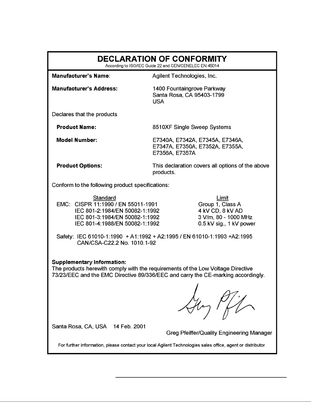
Compliance with EEC Directives
See the declaration of conformity on the following page.
x 8510XF Network Analyzer Systems
Page 11
Compliance with Standards
8510XF Network Analyzer Systems xi
Page 12

Compliance with Standards
xii 8510XF Network Analyzer Systems
Page 13

Contents
Notice . . . . . . . . . . . . . . . . . . . . . . . . . . . . . . . . . . . . . . . . . . . . . . . . . . . . . ii
What You’ll Find in This Manual… . . . . . . . . . . . . . . . . . . . . . . . . . . . . . iii
Warranty . . . . . . . . . . . . . . . . . . . . . . . . . . . . . . . . . . . . . . . . . . . . . . . . . . . iv
Certification . . . . . . . . . . . . . . . . . . . . . . . . . . . . . . . . . . . . . . . . . . . . . iv
DOCUMENTATION WARRENTY . . . . . . . . . . . . . . . . . . . . . . . . . . . iv
Assistance . . . . . . . . . . . . . . . . . . . . . . . . . . . . . . . . . . . . . . . . . . . . . . . iv
Contacting Agilent . . . . . . . . . . . . . . . . . . . . . . . . . . . . . . . . . . . . . . . . . . . v
Safety and Regulatory Information . . . . . . . . . . . . . . . . . . . . . . . . . . . . . . vi
Safety Requirements . . . . . . . . . . . . . . . . . . . . . . . . . . . . . . . . . . . . . . vii
Safety Earth Ground . . . . . . . . . . . . . . . . . . . . . . . . . . . . . . . . . . . . . . vii
Before Applying Power . . . . . . . . . . . . . . . . . . . . . . . . . . . . . . . . . . viii
Typeface Conventions . . . . . . . . . . . . . . . . . . . . . . . . . . . . . . . . . . . . . . . ix
Compliance with Standards . . . . . . . . . . . . . . . . . . . . . . . . . . . . . . . . . . . . x
1. Introduction
Finding System Information . . . . . . . . . . . . . . . . . . . . . . . . . . . . . . . . . . 1-2
Sources of Information . . . . . . . . . . . . . . . . . . . . . . . . . . . . . . . . . . . 1-2
8510XF Network Analyzer Systems . . . . . . . . . . . . . . . . . . . . . . . . . . . 1-4
System Description . . . . . . . . . . . . . . . . . . . . . . . . . . . . . . . . . . . . . . . . . 1-5
Two Versions of the 8510XF . . . . . . . . . . . . . . . . . . . . . . . . . . . . . . 1-5
What’s Included . . . . . . . . . . . . . . . . . . . . . . . . . . . . . . . . . . . . . . . . 1-5
Frequency Limits . . . . . . . . . . . . . . . . . . . . . . . . . . . . . . . . . . . . . . . 1-5
Partial Systems . . . . . . . . . . . . . . . . . . . . . . . . . . . . . . . . . . . . . . . . . 1-5
Options . . . . . . . . . . . . . . . . . . . . . . . . . . . . . . . . . . . . . . . . . . . . . . . . . . 1-8
Option 005 (45 MHz to 2 GHz) . . . . . . . . . . . . . . . . . . . . . . . . . . . . 1-8
Option 006 (RF Passthrough) . . . . . . . . . . . . . . . . . . . . . . . . . . . . . . 1-8
Option 010 (Time Domain) . . . . . . . . . . . . . . . . . . . . . . . . . . . . . . . 1-9
Option 230 (Line Voltage) . . . . . . . . . . . . . . . . . . . . . . . . . . . . . . . . 1-9
Upgrade Paths . . . . . . . . . . . . . . . . . . . . . . . . . . . . . . . . . . . . . . . . . . . . 1-10
2. Installation
Site Preparation . . . . . . . . . . . . . . . . . . . . . . . . . . . . . . . . . . . . . . . . . . . . 2-2
Power Requirements . . . . . . . . . . . . . . . . . . . . . . . . . . . . . . . . . . . . . 2-2
Environmental Requirements . . . . . . . . . . . . . . . . . . . . . . . . . . . . . . 2-3
Receiving the System . . . . . . . . . . . . . . . . . . . . . . . . . . . . . . . . . . . . . . . 2-5
The System as Shipped . . . . . . . . . . . . . . . . . . . . . . . . . . . . . . . . . . . 2-5
Agilent Technologies Customer Engineering . . . . . . . . . . . . . . . . . . 2-5
In Case of Problems with the Shipment . . . . . . . . . . . . . . . . . . . . . . 2-5
Precautions . . . . . . . . . . . . . . . . . . . . . . . . . . . . . . . . . . . . . . . . . . . . . . . 2-9
Safe Installation . . . . . . . . . . . . . . . . . . . . . . . . . . . . . . . . . . . . . . . . 2-9
Electrostatic Discharge . . . . . . . . . . . . . . . . . . . . . . . . . . . . . . . . . . 2-10
System Voltages . . . . . . . . . . . . . . . . . . . . . . . . . . . . . . . . . . . . . . . 2-10
8510XF Network Analyzer Systems Operating and Service Manual Contents xiii
Page 14

Test Port Inputs . . . . . . . . . . . . . . . . . . . . . . . . . . . . . . . . . . . . . . . . 2-10
Cleaning . . . . . . . . . . . . . . . . . . . . . . . . . . . . . . . . . . . . . . . . . . . . . 2-10
Unpacking the System . . . . . . . . . . . . . . . . . . . . . . . . . . . . . . . . . . . . . . 2-11
Tools Required . . . . . . . . . . . . . . . . . . . . . . . . . . . . . . . . . . . . . . . . 2-11
Basic System Configurations . . . . . . . . . . . . . . . . . . . . . . . . . . . . . . . . . 2-17
Installing the Work Surface . . . . . . . . . . . . . . . . . . . . . . . . . . . . . . . 2-20
Millimeter-Wave Controller . . . . . . . . . . . . . . . . . . . . . . . . . . . . . . . . . 2-23
LEDs . . . . . . . . . . . . . . . . . . . . . . . . . . . . . . . . . . . . . . . . . . . . . . . . 2-23
Connectors (Port 1) . . . . . . . . . . . . . . . . . . . . . . . . . . . . . . . . . . . . . 2-24
Connectors (Port 2) . . . . . . . . . . . . . . . . . . . . . . . . . . . . . . . . . . . . . 2-24
GPIB Address Switch . . . . . . . . . . . . . . . . . . . . . . . . . . . . . . . . . . . 2-25
Fuse . . . . . . . . . . . . . . . . . . . . . . . . . . . . . . . . . . . . . . . . . . . . . . . . . 2-25
Test Heads . . . . . . . . . . . . . . . . . . . . . . . . . . . . . . . . . . . . . . . . . . . . . . . 2-26
Connector Positions . . . . . . . . . . . . . . . . . . . . . . . . . . . . . . . . . . . . 2-26
Power Supply Inputs . . . . . . . . . . . . . . . . . . . . . . . . . . . . . . . . . . . . 2-26
Illustrations . . . . . . . . . . . . . . . . . . . . . . . . . . . . . . . . . . . . . . . . . . . 2-26
Test Ports . . . . . . . . . . . . . . . . . . . . . . . . . . . . . . . . . . . . . . . . . . . . . 2-27
Controller / Test Head Interconnections . . . . . . . . . . . . . . . . . . . . . . . . 2-28
Systems With Option 005 . . . . . . . . . . . . . . . . . . . . . . . . . . . . . . . . 2-28
Instruments Without Option 005 . . . . . . . . . . . . . . . . . . . . . . . . . . . 2-30
Cable List . . . . . . . . . . . . . . . . . . . . . . . . . . . . . . . . . . . . . . . . . . . . . . . . 2-32
Duplicate Listings . . . . . . . . . . . . . . . . . . . . . . . . . . . . . . . . . . . . . . 2-32
Turning On the System . . . . . . . . . . . . . . . . . . . . . . . . . . . . . . . . . . . . . 2-38
System Operational Test . . . . . . . . . . . . . . . . . . . . . . . . . . . . . . . . . . . . 2-39
Test Procedure . . . . . . . . . . . . . . . . . . . . . . . . . . . . . . . . . . . . . . . . . 2-40
Operating Notes . . . . . . . . . . . . . . . . . . . . . . . . . . . . . . . . . . . . . . . . . . . 2-42
3. Operation
8510XF Operating System . . . . . . . . . . . . . . . . . . . . . . . . . . . . . . . . . . . 3-2
Checking the Operating System . . . . . . . . . . . . . . . . . . . . . . . . . . . . 3-2
Measurement Calibration . . . . . . . . . . . . . . . . . . . . . . . . . . . . . . . . . . . . . 3-6
Why Calibration Is Essential . . . . . . . . . . . . . . . . . . . . . . . . . . . . . . . 3-6
When to Repeat the Calibration . . . . . . . . . . . . . . . . . . . . . . . . . . . . 3-6
Calibration Techniques . . . . . . . . . . . . . . . . . . . . . . . . . . . . . . . . . . . 3-7
Types of Calibration Kits . . . . . . . . . . . . . . . . . . . . . . . . . . . . . . . . . 3-7
Calibration Procedure . . . . . . . . . . . . . . . . . . . . . . . . . . . . . . . . . . . . . . . 3-9
Load Calibration Constants . . . . . . . . . . . . . . . . . . . . . . . . . . . . . . . . 3-9
Set Up the Analyzer . . . . . . . . . . . . . . . . . . . . . . . . . . . . . . . . . . . . . 3-9
Connect and Measure the Calibration Standards . . . . . . . . . . . . . . 3-10
Choosing Calibration Standards . . . . . . . . . . . . . . . . . . . . . . . . . . . . . . 3-11
Connector Sex . . . . . . . . . . . . . . . . . . . . . . . . . . . . . . . . . . . . . . . . . 3-11
Offset Shorts . . . . . . . . . . . . . . . . . . . . . . . . . . . . . . . . . . . . . . . . . . 3-11
Banded Standards . . . . . . . . . . . . . . . . . . . . . . . . . . . . . . . . . . . . . . 3-12
Non-Banded Standards . . . . . . . . . . . . . . . . . . . . . . . . . . . . . . . . . . 3-12
Calibration Types . . . . . . . . . . . . . . . . . . . . . . . . . . . . . . . . . . . . . . . . . . 3-13
S22 1-Port . . . . . . . . . . . . . . . . . . . . . . . . . . . . . . . . . . . . . . . . . . . . 3-16
Standard Types . . . . . . . . . . . . . . . . . . . . . . . . . . . . . . . . . . . . . . . . . . . 3-20
Contents xiv 8510XF Network Analyzer Systems Operating and Service Manual
Page 15

Standards Already Described . . . . . . . . . . . . . . . . . . . . . . . . . . . . . 3-20
Other Standards . . . . . . . . . . . . . . . . . . . . . . . . . . . . . . . . . . . . . . . 3-20
Port Power . . . . . . . . . . . . . . . . . . . . . . . . . . . . . . . . . . . . . . . . . . . . . . . 3-28
RF Power . . . . . . . . . . . . . . . . . . . . . . . . . . . . . . . . . . . . . . . . . . . . . . . 3-30
RF Power Configuration . . . . . . . . . . . . . . . . . . . . . . . . . . . . . . . . . 3-30
LO Power . . . . . . . . . . . . . . . . . . . . . . . . . . . . . . . . . . . . . . . . . . . . . . . 3-36
LO Power Configuration . . . . . . . . . . . . . . . . . . . . . . . . . . . . . . . . 3-36
LO Power Settings . . . . . . . . . . . . . . . . . . . . . . . . . . . . . . . . . . . . . 3-37
Service . . . . . . . . . . . . . . . . . . . . . . . . . . . . . . . . . . . . . . . . . . . . . . . . . . 3-38
85102 Service . . . . . . . . . . . . . . . . . . . . . . . . . . . . . . . . . . . . . . . . . 3-38
Leveling Settings . . . . . . . . . . . . . . . . . . . . . . . . . . . . . . . . . . . . . . 3-41
IF Frequency . . . . . . . . . . . . . . . . . . . . . . . . . . . . . . . . . . . . . . . . . . . . . 3-42
Alternative 1.0 mm Calibrations . . . . . . . . . . . . . . . . . . . . . . . . . . . . . . 3-43
Broadband Standards . . . . . . . . . . . . . . . . . . . . . . . . . . . . . . . . . . . 3-43
Operation Using a Wafer Probe Station . . . . . . . . . . . . . . . . . . . . . . . . 3-46
System Configuration . . . . . . . . . . . . . . . . . . . . . . . . . . . . . . . . . . . 3-46
Available Equipment . . . . . . . . . . . . . . . . . . . . . . . . . . . . . . . . . . . 3-47
Device Connections . . . . . . . . . . . . . . . . . . . . . . . . . . . . . . . . . . . . 3-47
Types of Probe Stations . . . . . . . . . . . . . . . . . . . . . . . . . . . . . . . . . 3-47
4. Performance Verification
When to Verify . . . . . . . . . . . . . . . . . . . . . . . . . . . . . . . . . . . . . . . . . 4-2
Materials Required . . . . . . . . . . . . . . . . . . . . . . . . . . . . . . . . . . . . . 4-3
Calibration and Frequency Ranges . . . . . . . . . . . . . . . . . . . . . . . . . . 4-3
Verification Setup . . . . . . . . . . . . . . . . . . . . . . . . . . . . . . . . . . . . . . . . . 4-5
General Preparation . . . . . . . . . . . . . . . . . . . . . . . . . . . . . . . . . . . . . 4-5
Software Installation . . . . . . . . . . . . . . . . . . . . . . . . . . . . . . . . . . . . . 4-5
Software Configuration . . . . . . . . . . . . . . . . . . . . . . . . . . . . . . . . . . 4-6
Verification Procedures . . . . . . . . . . . . . . . . . . . . . . . . . . . . . . . . . . . . . 4-9
Low Band Verification (< 50 GHz) . . . . . . . . . . . . . . . . . . . . . . . . . 4-9
CW Frequency Accuracy Test . . . . . . . . . . . . . . . . . . . . . . . . . . . . . . . 4-14
Materials Required . . . . . . . . . . . . . . . . . . . . . . . . . . . . . . . . . . . . . 4-14
Procedure . . . . . . . . . . . . . . . . . . . . . . . . . . . . . . . . . . . . . . . . . . . . 4-14
Performance Test Record . . . . . . . . . . . . . . . . . . . . . . . . . . . . . . . . 4-16
5. System Maintenance
Electrostatic Discharge . . . . . . . . . . . . . . . . . . . . . . . . . . . . . . . . . . . . . . 5-2
1.0 mm Connector Care . . . . . . . . . . . . . . . . . . . . . . . . . . . . . . . . . . . . . 5-3
Detector Gain Calibration . . . . . . . . . . . . . . . . . . . . . . . . . . . . . . . . . . . . 5-6
Purpose of the Calibration . . . . . . . . . . . . . . . . . . . . . . . . . . . . . . . . 5-6
The Calibration Process . . . . . . . . . . . . . . . . . . . . . . . . . . . . . . . . . . 5-6
When to Calibrate . . . . . . . . . . . . . . . . . . . . . . . . . . . . . . . . . . . . . . . 5-6
Procedure . . . . . . . . . . . . . . . . . . . . . . . . . . . . . . . . . . . . . . . . . . . . . 5-7
Conversion Loss Calibration . . . . . . . . . . . . . . . . . . . . . . . . . . . . . . . . . . 5-8
Purpose of the Calibration . . . . . . . . . . . . . . . . . . . . . . . . . . . . . . . . 5-8
The Calibration Process . . . . . . . . . . . . . . . . . . . . . . . . . . . . . . . . . . 5-8
When to Calibrate . . . . . . . . . . . . . . . . . . . . . . . . . . . . . . . . . . . . . . . 5-8
Agilent Technologies Customer Engineering . . . . . . . . . . . . . . . . . . 5-8
8510XF Network Analyzer Systems Operating and Service Manual Contents xv
Page 16

Theory of Operation . . . . . . . . . . . . . . . . . . . . . . . . . . . . . . . . . . . . . . . . 5-9
Signal Separation . . . . . . . . . . . . . . . . . . . . . . . . . . . . . . . . . . . . . . . 5-9
Frequency Control . . . . . . . . . . . . . . . . . . . . . . . . . . . . . . . . . . . . . . 5-10
The Leveling Loop . . . . . . . . . . . . . . . . . . . . . . . . . . . . . . . . . . . . . 5-15
Level Calibration . . . . . . . . . . . . . . . . . . . . . . . . . . . . . . . . . . . . . . . 5-18
LO Levels . . . . . . . . . . . . . . . . . . . . . . . . . . . . . . . . . . . . . . . . . . . . 5-19
System Block Diagrams . . . . . . . . . . . . . . . . . . . . . . . . . . . . . . . . . . . . 5-21
110 GHz Systems . . . . . . . . . . . . . . . . . . . . . . . . . . . . . . . . . . . . . . 5-21
Troubleshooting . . . . . . . . . . . . . . . . . . . . . . . . . . . . . . . . . . . . . . . . . . . 5-37
Cycle Power . . . . . . . . . . . . . . . . . . . . . . . . . . . . . . . . . . . . . . . . . . 5-37
Hardware Configuration Check . . . . . . . . . . . . . . . . . . . . . . . . . . . . 5-37
Firmware Configuration Check . . . . . . . . . . . . . . . . . . . . . . . . . . . . 5-38
6. Replaceable Parts
Parts Listed . . . . . . . . . . . . . . . . . . . . . . . . . . . . . . . . . . . . . . . . . . . . 6-2
How to Order . . . . . . . . . . . . . . . . . . . . . . . . . . . . . . . . . . . . . . . . . . . 6-2
Frequency Ranges . . . . . . . . . . . . . . . . . . . . . . . . . . . . . . . . . . . . . . . 6-2
Categorization of Components . . . . . . . . . . . . . . . . . . . . . . . . . . . . . 6-3
110 GHz Systems . . . . . . . . . . . . . . . . . . . . . . . . . . . . . . . . . . . . . . . . . . 6-4
Complete System . . . . . . . . . . . . . . . . . . . . . . . . . . . . . . . . . . . . . . . 6-4
85 GHz Systems . . . . . . . . . . . . . . . . . . . . . . . . . . . . . . . . . . . . . . . . . . . 6-7
Complete System . . . . . . . . . . . . . . . . . . . . . . . . . . . . . . . . . . . . . . . 6-7
Millimeter-Wave Controller . . . . . . . . . . . . . . . . . . . . . . . . . . . . . . . . . 6-10
7. Menus & Commands
Menu Maps . . . . . . . . . . . . . . . . . . . . . . . . . . . . . . . . . . . . . . . . . . . . . . . 7-2
New GPIB Commands . . . . . . . . . . . . . . . . . . . . . . . . . . . . . . . . . . . . . 7-43
Unsupported GPIB Commands . . . . . . . . . . . . . . . . . . . . . . . . . . . . . . . 7-47
New Messages . . . . . . . . . . . . . . . . . . . . . . . . . . . . . . . . . . . . . . . . . . . . 7-49
Contents xvi 8510XF Network Analyzer Systems Operating and Service Manual
Page 17

1 Introduction
In This Chapter...
Finding System Information, page 1-2
•
• 8510XF Network Analyzer Systems, page 1-4
• System Description, page 1-5
• Options, page 1-8
• Upgrade Paths, page 1-10
8510XF Network Analyzer Systems 1-1
Page 18

Introduction
Finding System Information
Finding System Information
Sources of Information Documents provided with the 8510XF include the following:
Table 1-1 Documents Supplied with the System
Document Part Number Description
8510XF Operation and Service Manual E7350-90001 8510XF system manual
8510C Network Analyzer Manuals set 08510-90275 includes:
8510C Operating and Programming Manual 08510-90281 A detailed operator’s guide to the
8510C network analyzer
8510C Introductory User’s Guide 08510-90290 A brief introduction to functions,
menus, and measurement setups
for the 8510C network analyzer
8510C Quick Reference Guide 08510-90292 An abbreviated, pocket-sized guide
to codes, commands, and menu
maps for the 8510C network
analyzer
8510C Keyword Dictionary 08510-90280 A thorough presentation of codes,
commands, and menu maps for the
8510C network analyzer
8510C On-Site Service Manual 08510-90282 A detailed guide to maintenance
and troubleshooting for the 8510C
network analyzer
8360 Series Dedicated Source Manual set 08360-90138 includes:
83651B & 83621B Manuals 08360-90136
08360-90137
Troubleshooting and service
manuals for the RF source and LO
source
Another important document is the Operating and Service Manual for the
85059A 1.0 mm Precision Calibration and Verification Kit (the Agilent part
number of the manual is 85059-90003).
1-2 8510XF Network Analyzer Systems
Page 19

Introduction
Finding System Information
Where to look The following table shows where to look first (and second) for particular
kinds of information.
Table 1-2 Primary and Secondary Information Sources
Subject First Source Other Sources
Installing the system Chapter 2 of this manual Chapter 9, 8510C On-Site Service Manual
Using menus Chapter 3 of this manual
(also see Chapter 7 for menu maps)
Using system functions Chapter 3 of this manual Chapter 5, 8510C Operating and Programming
Measurement calibration Chapter 3 of this manual Chapter 8, 8510C Operating and Programming
Verifying performance Chapter 4 of this manual Chapter 8, 8510C On-Site Service Manual
Maintenance Chapter 5 of this manual Chapters 7 & 10, 8510C On-Site Service Manual
Ordering replacement parts Chapter 6 of this manual Chapter 5, 8510C On-Site Service Manual
GPIB programming Chapter 7 of this manual Chapter 13, 8510C Operating and Programming
Basics of network analysis 8510C Introductory User’s Guide Chapter 3, 8510C Operating and Programming
Types of measurement 8510C Operating and Programming Manual:
• Chapter 9 (Transmission)
• Chapter 10 (Reflection)
• Chapter 11 (Time Domain)
• Chapter 12 (Power Domain)
Chapter 4, 8510C Operating and Programming
Manual
Manual
Manual
Also: Supplement to 8510C Operating and
Programming Manual (“Operator’s Check and
Routine Maintenance”)
Manual
Also: 8510C Quick Reference Guide
Also: 8510C Keyword Dictionary
Manual
Chapter 3 of this manual
Printing & plotting Chapter 6, 8510C Operating and Programming
Manual
Using the disk drive Chapter 7, 8510C Operating and Programming
Manual
8510XF Network Analyzer Systems 1-3
Page 20
Introduction
8510XF Network Analyzer Systems
8510XF Network Analyzer Systems
The 8510XF is a vector network analyzer with an extremely wide frequency
range. It is available in two basic versions, with frequency ranges of
2 to 85 GHz and 2 to 110 GHz. Both ranges can be optionally extended
downward to 45 MHz.
The 8510XF uses the same test port connections throughout its entire range
of test frequencies. It is never necessary to make and break connections in
order to complete a test.
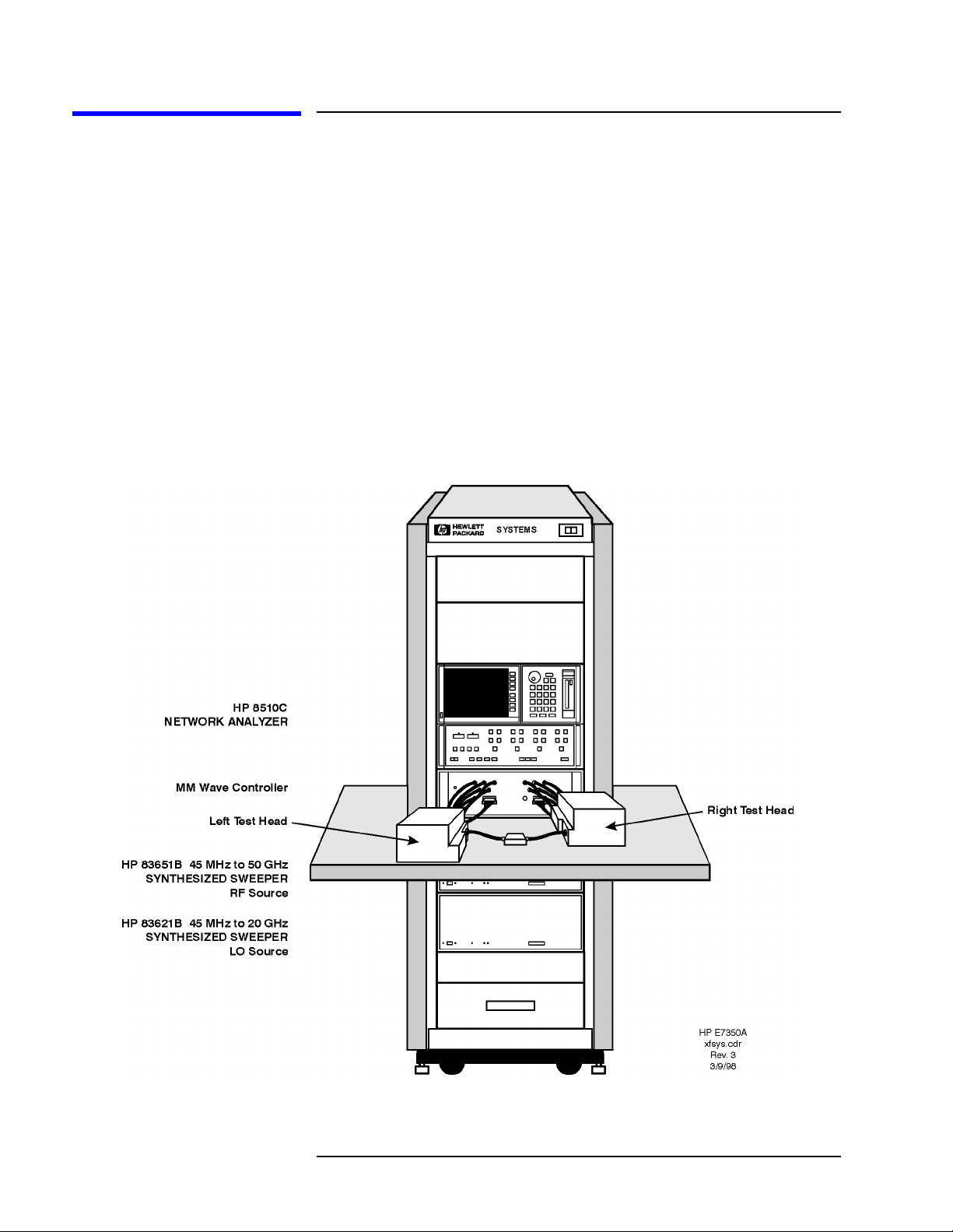
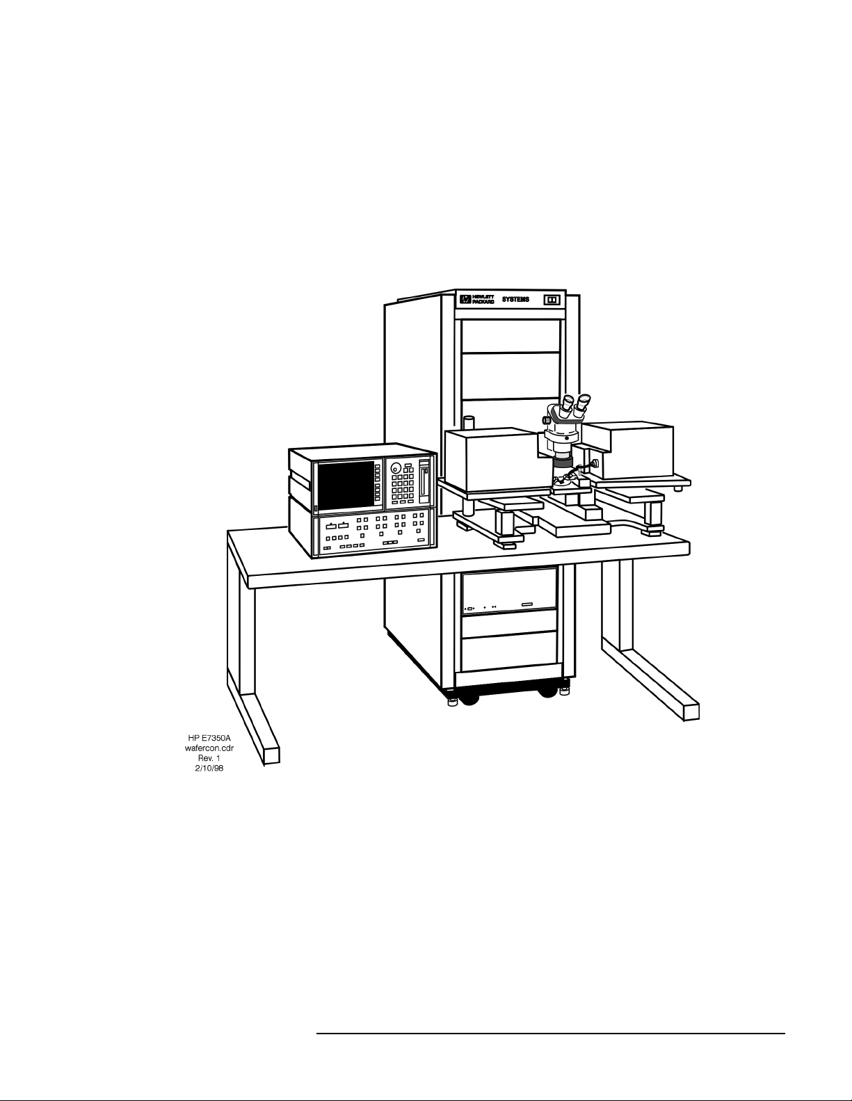
The illustration below shows the 8510XF configured for coaxial
measurement; the system can also be configured for on-wafer measurement
using a wafer probe test station.
Figure 1-1 8510XF Network Analyzer System
1-4 8510XF Network Analyzer Systems
Page 21

System Description
Introduction
System Description
Two Versions of the 8510XF
The system is available in two basic versions, distinguished by their upper
frequency limits. The 85 GHz version is ordered as E7340A; the 110 GHz
version is ordered as E7350A.
What’s Included The major components of the 8510XF system are:
• Network analyzer, 8510C
• Synthesized RF source, 83651B
• Synthesized LO source, 83621B
• Millimeter-wave controller, E7341A
• Left test head, E7342L (85 GHz) or E7352L (110 GHz)
• Right test head, E7342R (85 GHz) or E7352R (110 GHz)
• 1.6 meter instrument rack (E3661A)
Frequency Limits As the list above indicates, the upper frequency limit of the system is
determined by the type of test head that is included in it.
The lower frequency limit of an 8510XF system is normally 2 GHz. With
Option 005 installed, the lower frequency limit is 45 MHz. (See “Options”
on page 1-8.)
Partial Systems Customers who already have the network analyzer and the sources can order
partial systems which omit those items. The partial systems are known as
millimeter-wave subsystems; the 85 GHz version is ordered as E7342A, and
the 110 GHz version is ordered as E7352A.
In addition, 8510XF upgrade kits are available for other Agilent test systems
(see “Upgrade Paths” on page 1-10).
8510XF Network Analyzer Systems 1-5
Page 22
Introduction
System Description
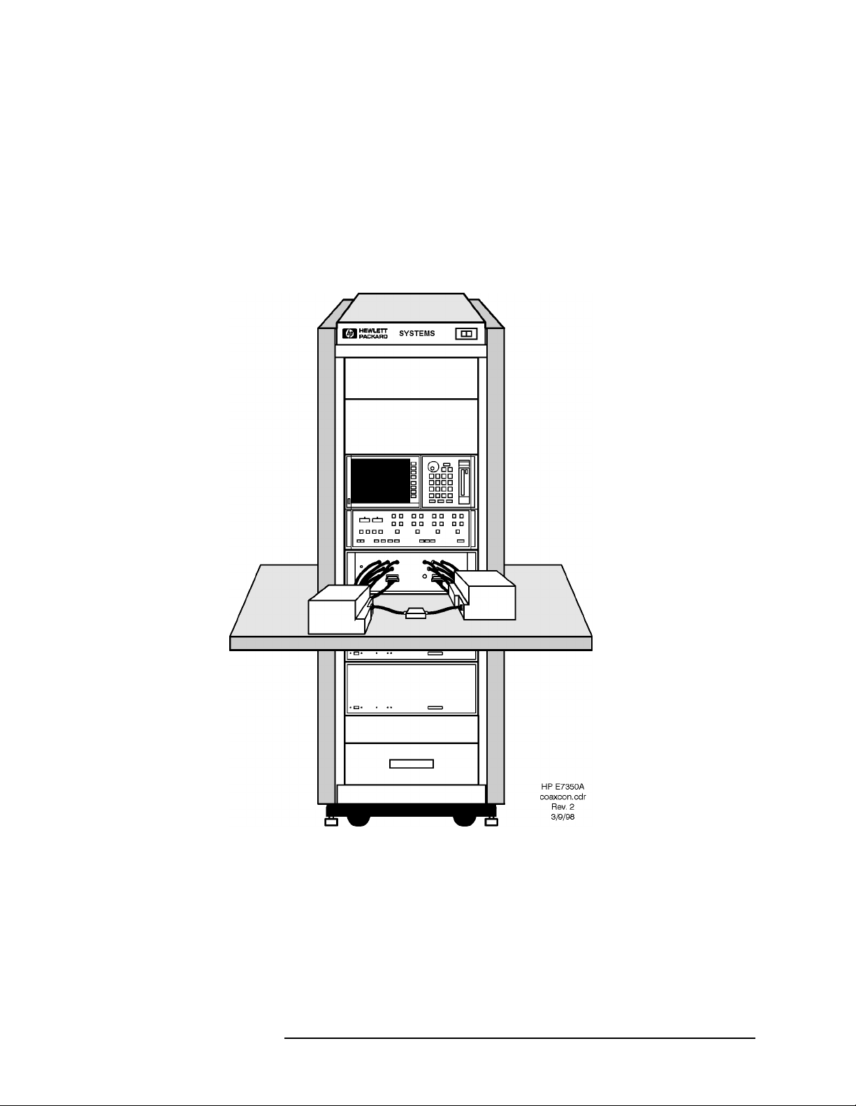
Coaxial Configuration When the 8510XF is configured for measurement through coaxial
connections, the network analyzer, the millimeter-wave controller, and the
RF and LO sources are all installed in the rack. The test heads are placed on
a work surface which is mounted below the millimeter-wave controller.
The test ports feature 1.0 mm coaxial connectors. The device under test is
typically connected to one test port directly, and to the other test port by way
of a coaxial cable (or it is connected to the ports through two coaxial cables).
Figure 1-2 8510XF, Configured for Coaxial Measurement
1-6 8510XF Network Analyzer Systems
Page 23
Introduction
System Description
Wafer Probe
Configuration
For on-wafer measurements, it is usually best to remove the network
analyzer from the instrument rack, and place it on a table adjacent to the
probe station. This makes it easy to see and operate the analyzer.
No wafer probe station is supplied with the system; the illustration below
simply shows how the 8510XF combines with a typical probe station to
create an on-wafer measurement system.
Figure 1-3 8510XF, Configured for Wafer-Probe Measurement
8510XF Network Analyzer Systems 1-7
Page 24
Introduction
Options
Options
Option 005
(45 MHz to 2 GHz)
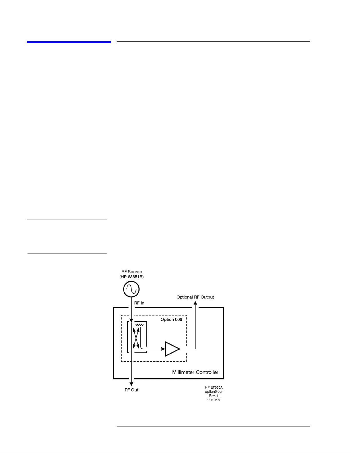
Option 006
(RF Passthrough)
NOTE The 8510XF firmware does not support multiple test sets. In order to use the
This option extends the lower limit of the 8510XF frequency range
downward to 45 MHz. The option is implemented by adding four
low-frequency mixers, which are dedicated to the .045 to 2 GHz frequency
range. These mixers are installed in the millimeter-wave controller.
This option adds a coupler, amplifier, and RF output connector to the
millimeter-wave controller. The purpose is to make the RF input to the
controller (which is supplied by the 83651B RF source) available as an
output, so that it can be routed to other devices or test sets.
The RF output on the rear panel of the millimeter-wave controller is a
2.4 mm coaxial connector. To supply this RF output to another test set, you
will need a 2.4 mm coaxial cable of adequate length (this cable is not
supplied with the 8510XF).
The system is shipped with a 50 Ω load attached to the RF output connector.
Option 006 RF output as the RF source for another test set, you must load
the standard 8510C firmware (from a diskette which is supplied with the
8510XF).
Figure 1-4 Option 006
1-8 8510XF Network Analyzer Systems
Page 25

Introduction
Options
Option 010
(Time Domain)
NOTE Option 010 is available only for complete systems (E7340A and E7350A).
Option 230
This option makes it possible to use the 8510XF in time domain mode. The
option is implemented through modification of the network analyzer
operating system.
This option configures the 8510XF for 220/240 line voltage operation.
(Line Voltage)
8510XF Network Analyzer Systems 1-9
Page 26

Introduction
Upgrade Paths
Upgrade Paths
Kits are available for upgrading another type of 8510C test system to an
8510XF system, as described below.
Upgrade Kits for the
85107A/B
Table 1-3 Contents of Upgrade Kits for the 85107A/B
An 85107A/B can be upgraded to an 8510XF, in either the 110 GHz version
(upgrade kit E7355A) or the 85 GHz version (upgrade kit E7345A).
Item Part#
Millimeter-wave controller E7341A
Left test head E7342L (85 GHz)
or E7352L (110 GHz)
Right test head E7342R (85 GHz)
or E7352R (110 GHz)
LO source 83621B
Rack flange kit for LO source 83621B #913
8510XF operating & service manual E7350-90001
E7345A/E7355A upgrade kit installation manual E7350-90003
8510XF system software on diskette E7340-10001
8 chips for expanding non-volatile memory in the 8510C 1818-4075
NOTE The upgrade kits for the 85107A/B can also be used for an 85109C system
which lacks Option 002. To upgrade an 85109C with Option 002, see the
upgrade kit described on page 1-12).
1-10 8510XF Network Analyzer Systems
Page 27

Introduction
Upgrade Paths
Upgrade Kits for the
85106C/D
Table 1-4 Contents of Upgrade Kits for the 85106C/D
An 85106C/D can be upgraded to an 8510XF, in either the 110 GHz version
(upgrade kit E7356A) or the 85 GHz version (upgrade kit E7346A).
Item Part#
Millimeter-wave controller E7341A
Left test head E7342L (85 GHz)
or E7352L (110 GHz)
Right test head E7342R (85 GHz)
or E7352R (110 GHz)
RF source 83651B
Rack flange kit for RF source 83651B #913
8510XF operating & service manual E7350-90001
E7346A/E7356A upgrade kit installation manual E7350-90004
8510XF system software on diskette E7340-10001
8 chips for expanding non-volatile memory in the 8510C 1818-4075
8510XF Network Analyzer Systems 1-11
Page 28

Introduction
Upgrade Paths
Upgrade Kits for the
85109C
(With Option 002)
Table 1-5 Contents of Upgrade Kits for the 85109C
An 85109C with Option 002 can be upgraded to an 8510XF, in either the
110 GHz version (upgrade kit E7357A) or the 85 GHz version (upgrade kit
E7347A).
Item Part#
Millimeter-wave controller E7341A
Left test head E7342L (85 GHz)
or E7352L (110 GHz)
Right test head E7342R (85 GHz)
or E7352R (110 GHz)
8510XF operating & service manual E7350-90001
E7347A/E7357A upgrade kit installation manual E7350-90005
8510XF system software on diskette E7340-10001
8 chips for expanding non-volatile memory in the 8510C 1818-4075
NOTE To upgrade an 85109C which lacks Option 002, see the upgrade kit
described on page 1-10.
1-12 8510XF Network Analyzer Systems
Page 29

2 Installation
In This Chapter...
Site Preparation, page 2-2
Power Requirements, page 2-2
Environmental Requirements, page 2-3
Receiving the System, page 2-5
Precautions, page 2-9
Unpacking the System, page 2-11
Basic System Configurations, page 2-17
Millimeter-Wave Controller, page 2-23
Test Heads, page 2-26
Controller / Test Head Interconnections, page 2-28
Cable List, page 2-32
Other Connections and Settings, page 2-37
Turning On the System, page 2-38
System Operational Test, page 2-39
Operating Notes, page 2-42
8510XF Network Analyzer Systems 2-1
Page 30

Installation
Site Preparation
Site Preparation
Power Requirements Before installing the system, be sure that the required ac power is available
at all necessary locations.
• Three-wire power cables (which provide a safety ground) must be used
with all instruments.
• Air-conditioningequipment (or other motor-operated equipment) should
not be placed on the same ac line that powers the system.
• The table below lists the maximum VA ratings and BTU/hour ratings for
all instruments in the system. This table can be used to determine both
the electrical requirements and the air conditioning requirements of the
system.
Table 2-1 Power requirements of the system
Standard Equipment
Instrument Maximum VA Rating Maximum BTU/hour
85101C display processor 250 850
85102B IF detector 210 714
83621B synthesized source (LO) 400 1360
83651B synthesized source (RF) 400 1360
E7341A millimeter-wave controller 500 1700
E7342L left test head (85 GHz)
or E7352L left test head (110 GHz)
E7342R right test head (85 GHz)
or E7352R right test head (110 GHz)
Total 1760 5984
NOTES:
(1) Values are based on 120 Vac supplied to each instrument at 60 Hz.
(2) The millimeter-wave controller supplies power to the test heads.
(powered from controller) (powered from controller)
(powered from controller) (powered from controller)
2-2 8510XF Network Analyzer Systems
Page 31

Installation
Site Preparation
Environmental Requirements
The environmental requirements of the system are listed in the table below.
Note that these requirements are the same as those of the 8510C Network
Analyzer.
Table 2-2 Environmental Requirements
Temperature (Operation) 5 °C to 40 °C (41 °F to 104 °F)
Temperature (Storage) −40
Temperature (Measurement Calibration) 20
Temperature (Performance Verification) Temperature must be within 1
Relative Humidity (Operation) 5% to 95% at 40
Relative Humidity (Storage) 5% to 95% at 65
Pressure Altitude (Operation or Storage) Less than 4600 meters (~15,000 feet)
System heating and cooling
°C to +65 °C (-40 °F to +158 °F)
°C to 26 °C (68 °F to 79 °F)
°C (1.8 °F) of the
temperature at which the measurement
calibration was performed.
°C or less (non-condensing)
°C or less (non-condensing)
Install air conditioning and heating, if necessary to maintain the ambient
temperature within the appropriate range (as given in the table above). Air
conditioning capacity must be consistent with the BTU ratings given in the
table under “Power Requirements” on page 2-2.
Required conditions for accuracy-enhanced measurement
Accuracy-enhanced (error-corrected) measurements require the ambient
temperature of the 8510XF to be maintained within ±1°C of the ambient
temperature at calibration.
8510XF Network Analyzer Systems 2-3
Page 32

Installation
Site Preparation
Weight and dimensions
The table below shows the maximum weight and dimensions of the 8510XF
system, as installed in the system rack, with the test heads on an attached
work surface.
Table 2-3 System Weight and Dimensions
Weight Height Width Depth
280.3 kg (618 lbs) 162 cm (63.8 in) Rack only: 60 cm (23.6 in)
Plus work surface: 100 cm (39.4 in)
The table below shows the weight and dimensions of a single test head (left
or right):
Table 2-4 Test Head Weight and Dimensions
Test Head Model Weight Height Width Depth
E7342 L/R 9.07 kg
(20 lb)
E7352 L/R 9.75 kg
(21.5 lb)
18.5 cm
(7.3 in)
18.5 cm
(7.3 in)
Rack Only: 90.5 cm (35.6 in)
Plus work surface: 145.4 cm (57.3 in)
24.7 cm
(9.7 in)
24.7 cm
(9.7 in)
31.4 cm
(12.4 in)
31.4 cm
(12.4 in)
Figure 2-1 Testhead Footprint Dimensions for Mounting (left or right)
2-4 8510XF Network Analyzer Systems
Page 33

Installation
Receiving the System
Receiving the System
The System as Shipped The 8510XF system will arrive with all rack components and instruments
installed and cabled in the system cabinet. The system cabinet is shipped
upright in a special crate (as illustrated in “Unpacking the System” on
page 2-11). The work surface is included in the system cabinet packaging.
The test heads are packaged separately from the system cabinet, in two
padded cartons.
When the entire shipment has arrived, contact your nearest Agilent
Technologies office to arrange for system installation, if installation is
available in your area (see “Contacting Agilent”).
Agilent Technologies Customer Engineering
In Case of Problems with the Shipment
An Agilent Technologies Customer Engineer will be assigned to help you
install the system. During installation, the Customer Engineer will do the
following:
• Uncrate the system cabinet (see “Unpacking the System” on page 2-11).
• Complete the system checklist (see “System Checklists” on page 2-7).
• Assemble the work surface and connect it to the system cabinet.
• Install the test heads.
• Verify that the GPIB addresses are set properly and power up the
system.
• Run a performance verification of the system, which includes a
measurement calibration.
• Provide user training for one engineer.
If the shipment is damaged or incomplete, notify the nearest Agilent
Technologies office. If the shipping container is damaged or the packaging
material shows signs of stress, notify the carrier as well as the Agilent
Technologies Customer Engineer. Keep the shipping materials for the
carrier’s inspection. Agilent Technologies will arrange for repair or
replacement of damaged equipment without waiting for a claim settlement
from the carrier.
8510XF Network Analyzer Systems 2-5
Page 34

Installation
Receiving the System
Shipping Containers Keep the shipping containers in one area until the system checklist has been
completed. This makes it easier to verify that everything ordered has been
shipped.
Keep the containers, and all packing materials, until the entire shipment has
been verified for completeness, and the system has been checked
mechanically and electrically. The crate may be used one more time only to
ship the 8510XF cabinet.
If you need to ship your 8510XF system, repackage it in its original shipping
crate. Make all surface shipments via padded van with an air suspension
ride.
CAUTION Regardless of the crate style, all surface shipments must be made via padded
van (air suspension ride). Surface shipments in vehicles without air
suspension may result in damage to the system components, cabinet, and
shipping crate.
2-6 8510XF Network Analyzer Systems
Page 35

Installation
Receiving the System
System Checklists Usethe tables below to verify that the shipment is complete. These are items
that are supplied (as indicated below) with E7340A or E7350A complete
systems only. For a list of items supplied with upgrade kits see “Upgrade
Paths” on page 1-10 through page 1-12.
Standard Items Items that are supplied with all 8510XF (E7340A or E7350A) systems are
listed in Table 2-5.
Table 2-5 8510XF System Checklist (Standard Items)
✔
Equipment Serial Number
8510C network analyzer
83621B synthesized source (LO source), with
83621B #913 rack flange kit
83651B synthesized source (RF source), with
83651B #913 rack flange kit
Millimeter-wave controller & test heads --
see “Optional/Variable Items” on page 2-8
E3661A system rack (1.6 meter)
Cables (for a complete list of cables supplied with the system,
see “Cable List” on page 2-32).
E7340-10001 (8510XF firmware diskette) N/A
System manual:
8510XF Operating and Service Manual, E7350-90001
Network analyzer manuals:
8510C Manual set 08510-90275
Source manuals:
83651B & 83621B Manual set 08360-90138
See page 2-8
N/A
N/A
N/A
N/A
8510XF Network Analyzer Systems 2-7
Page 36

Installation
Receiving the System
Optional/Variable Items Table 2-6 lists those items that are supplied only if the applicable frequency
range or option has been ordered with the 8510XF (E7340A or E7350A)
system.
Table 2-6 8510XF System Checklist (Optional/Variable Items)
Equipment Included In Serial Number
✔
Left test head:
E7342L
E7352L
Right test head:
E7342R
E7352R
Millimeter-wave controller:
E7341A
E7341A #005
E7341A #006
E7341A #056
Systems to 85 GHz
Systems to 110 GHz
Systems to 85 GHz
Systems to 110 GHz
Systems without options
Systems with Option 005
Systems with Option 006
Systems with Options 005 & 006
8510C #010 (time domain option for network analyzer) Systems with Option 010
85106-60038 (1 meter table top) E7340A and E7350A complete systems N/A
2-8 8510XF Network Analyzer Systems
Page 37

Installation
Precautions
Precautions
Safe Installation Install the system so that the ON/OFF switch is readily identifiable and is
easily reached by the operator. The ON/OFF switch or the detachable power
cord is the system disconnecting device. It disconnects the mains circuits
from the mains supply before other parts of the system. Alternatively, an
externally installed switch or circuit breaker (which is readily identifiable
and is easily reached by the operator) may be used as a disconnecting device.
Install the system according to the enclosure protection provided:
• The system protects against finger access to hazardous parts within the
enclosure.
• The system does not protect against the ingress of water.
CAUTION This product is designed for use in Installation Category II and Pollution
Degree 2 per IEC 1010 and 664 respectively.
CAUTION Always use the three-prong ac power cord supplied with this product.
Failure to insure adequate earth grounding by not using this cord may cause
product damage.
CAUTION Before switching on the system, make sure that the correct fuse is installed,
and that the supply voltage is in the specified range.
CAUTION Ventilation requirements:
Convection in and out of the system cabinet must not be restricted. The
ambient temperature (outside the cabinet) must be less than the maximum
operating temperature of the system by 4°C for every 100 watts dissipated in
the cabinet. If the total power dissipated in the cabinet is greater than 800
watts, then forced convection must be used.
WARNING This is a Safety Class 1 Product (provided with a protective earthing ground
incorporated in the power cord). The mains plug shall only be inserted in a
socket outlet provided with a protective earth contact. Any interruption of the
protective conductor inside or outside the product is likely to make the
product dangerous. Intentional interruption is prohibited.
8510XF Network Analyzer Systems 2-9
Page 38

Installation
Precautions
WARNING If this product is not used as specified, the protection provided by the
equipmentcould be impaired.This product must be usedin a normal condition
(in which all means for protection are intact) only.
Electrostatic Discharge
CAUTION The millimeter-wave controller and the test heads are sensitive to
electrostatic discharge (ESD). Ground your work station before unpacking
and installing the test heads. See “Electrostatic Discharge” on page 5-2 for
more information.
System Voltages All instruments in the 8510XF system must be set to the same voltage as the
system rack (either 120 Vac or 220 Vac). 120 Vac is the factory setting.
CAUTION The cabinet fans may be permanently damaged if a 120V system is plugged
into a 220V ac power outlet. The cabinet fans can be wired for either 120V
or 220V, but not both. Therefore, a system wired for 120V operation cannot
be switched to 230V operation simply by changing the voltage selection
switches on individual instruments.
Test Port Inputs
CAUTION Input power to the test ports must not exceed +27 dBm. Input power in
excess of this level will damage expensive components. Observe proper
precautions, especially when measuring amplifiers with gains of 20 dB or
greater.
Cleaning
WARNING To prevent electrical shock, disconnect the E734X/E735X mains before
cleaning. Use a dry cloth or one slightly dampened with water to clear the
external case parts. Do not attempt to clean internally.
2-10 8510XF Network Analyzer Systems
Page 39

Installation
Unpacking the System
Unpacking the System
Tools Required • 9/16 inch wrench or adjustable-end wrench
• Screwdriver (to pry off packing clamps)
CAUTION When you remove the clamps from the packing crates, be careful not to bend
them; they may be reused when the system is repacked.
Figure 2-2 The Outer Packing Crate
NOTE The figures show a double rack crate. The unpacking procedure is essentially
the same for either a single rack or a double rack crate (differences will be
noted where they occur).
8510XF Network Analyzer Systems 2-11
Page 40

Safety Glasses
Installation
Unpacking the System
Figure 2-3 Removing the Outer Packing Crate
WARNING Always wear safety glasses when removing the clamps and other packing
materials from the crates.
Remove the outer packing crate
1. Remove the clamps holding the packing crate top cover in place.
Remove the top cover and set it aside.
2. Remove the clamps holding the first packing crate wall in place. It does
not matter which wall you remove first.
3. Remove the other walls. Make sure you have people holding the last two
walls in place when you remove the last set of clamps.
4. Set the loading ramp aside for now.
NOTE In double-rack crates, the heaviest wall is the loading ramp. In single rack
crates, the loading ramp is shipped inside the package, placed on top of the
rack (it is a hinged assembly, shipped in the folded position).
2-12 8510XF Network Analyzer Systems
Page 41

Foam cover
Installation
Unpacking the System
Figure 2-4 Removing the Foam Cover and Plastic Wrapping
Remove the top cover and plastic wrapping
1. Remove the foam top cover. Save the cover for possible future use.
2. Remove the plastic wrapping from the system.
8510XF Network Analyzer Systems 2-13
Page 42

Installation
Unpacking the System
Figure 2-5 Removing the Bolts
Brace bolts (Item A)
Brace (Item B)
Figure 2-6 Removing the Anchor Bolt
Ramp anchor bolt (Item D)
Hinged slat (Item C)
Ramp Ledge
2-14 8510XF Network Analyzer Systems
Page 43

Ramp anchor bolt (Item D)
Ramp end flap
(hinged to ramp) (Item E)
Figure 2-7 Replacing the Anchor Bolt
Installation
Unpacking the System
Unload the system
1. Pull out the two bolts (item A) from the base using a screwdriver or
pliers. See Figure 2-5 on page 2-14.
2. Remove the brace assembly (item B).
3. Lift the hinged slat (item C) and remove the ramp anchor bolt (item D).
See Figure 2-6 on page 2-14.
4. Place one end of the ramp on the ramp ledge. See Figure 2-7 above.
5. Insert the ramp anchor bolt and fold down the hinged slat. To secure the
ramp, you may place long wood screws through the ramp and into the
ramp edge.
6. Fold down the ramp’s end flap (item E).
WARNING A racked system is tall and top-heavy. It is easy to tip the rack over while
movingit, which could result in personalinjury or death. Unloadingthe system
safely requires the participation of four persons, and they must exercise care
to prevent the rack from tipping over.
8510XF Network Analyzer Systems 2-15
Page 44

Installation
Unpacking the System
Figure 2-8 Moving the System Down the Ramp
7. Make sure the leveling feet are fully retracted and that the cabinet
casters are rolling freely.
WARNING Do not stand in front of the rack as it rolls down the ramp.
8. Roll the system down the ramp using extreme care.
9. In case you must move the system in the future, you can retain and reuse
these packing materials or you can purchase replacement packing
materials from Agilent Technologies.
2-16 8510XF Network Analyzer Systems
Page 45

Installation
Basic System Configurations
Basic System Configurations
The 8510XF can be used in either of two basic configurations, depending on
the means by which the test ports are connected to the device under test.
Coaxial measurement
This configuration is used when the device under test has
coaxial connectors. The 8510XF test ports have 1.0 mm
coaxial connectors, designed to cover a frequency range of
45 MHz to 110 GHz.
In this configuration, the test heads are placed on a work
surface which is attached to the instrument rack, slightly below
the millimeter-wave controller.
The device under test is normally connected to the test ports by
way of coaxial cables. It is also possible to connect the device
to one test port directly, and to the other test port by way of a
coaxial cable.
CAUTION Do not attempt to connect a test device directly between the two test ports,
without cables. The test heads will not move freely enough to allow such a
connection to be made safely.
Wafer probe measurement
This configuration is used for on-wafer testing; each test port is
connected (through a 1.0 mm coaxial cable, or through an
adapter and another type of coaxial cable) to a wafer test
probe. Contact the manufacturer of the wafer probe station and
an Agilent office for information on the cables and adapters
needed to connect the test heads to the wafer probe station
(refer to “Contacting Agilent” on page -v).
In this configuration, the test heads are placed on X-Y
positioners that are mounted to the wafer probe station.
It is usually best to remove the 8510C from the rack, and place
it on the work surface beside the probe station; this makes it
easier to see the network analyzer’s display and to reach its
front panel controls.
8510XF Network Analyzer Systems 2-17
Page 46

Installation
Basic System Configurations
Coaxial Configuration Figure 2-9 shows how the instruments are installed in the rack for the coaxial
configuration. The test heads (which are placed on the work surface) are
omitted here, in order to give an unobstructed view of the rack instruments.
Figure 2-9 Rack Diagram for Coaxial Configuration
Figure 2-10 on page 2-19 shows rack cabling for the coaxial configuration.
For cabling between the millimeter-wave controller and the test heads, see
“Controller / Test Head Interconnections” on page 2-28.
2-18 8510XF Network Analyzer Systems
Page 47

Installation
Basic System Configurations
Figure 2-10 Rear-View Cabling Diagram (Coaxial Configuration)
8510XF Network Analyzer Systems 2-19
Page 48

Installation
Basic System Configurations
Installing the Work Surface
NOTE The 1 meter table top is included in the E7340A and E7350A complete
The work surface is a 1 meter wide table top, to be attached to the system
rack just below the millimeter-wave controller.
1. Extend the lock feet (located at the bottom of the cabinet) to stabilize the
rack.
2. Attach the work surface support rails to the inside of the cabinet.
3. Slide the work surface onto the support rails.
systems. It is optional in the upgrade kits.
Figure 2-11 Installing the Work Surface
2-20 8510XF Network Analyzer Systems
Page 49

Installation
Basic System Configurations
Wafer Probe
Configuration
Figure 2-12 shows how the instruments are installed in the rack for the wafer
probe configuration. The test heads (which are placed on X-Y positioners
mounted to the wafer probe station) are omitted here, in order to give an
unobstructed view of the rack instruments.
Figure 2-12 Rack Diagram for Wafer Probe Configuration
Figure 2-13 shows rack cabling for the wafer probe configuration. For
cabling between the millimeter-wave controller and the test heads, see
“Controller / Test Head Interconnections” on page 2-28.
8510XF Network Analyzer Systems 2-21
Page 50

Installation
Basic System Configurations
Figure 2-13 Rear-view Cabling Diagram (Wafer-Probe Configuration)
2-22 8510XF Network Analyzer Systems
Page 51

Installation
Millimeter-Wave Controller
Millimeter-Wave Controller
The front panel of the millimeter-wave controller is illustrated below. (See
page 2-28 for information on controller/test head interconnections.)
Figure 2-14 Millimeter-Wave Controller
NOTE The illustration above shows the front panel of the controller as it appears in
systems with Option 005 (.045 MHz to 2 GHz range added). If the system
does not have Option 005, the four “RF Input” connectors (a1, b1, a2, and
b2) will be omitted.
LEDs Four LEDs are used as indicators on the front panel:
LINE Lights to indicate that line power to the controller is ON.
ACTIVE Lights to indicate that this is the active test set (useful in
distinguishing among multiple test sets tied to the same
analyzer).
a1 This LED, located at the upper left of the S-parameter
diagram, is lit when the RF source is switched to Port 1.
a2 This LED, located at the lower right of the S-parameter
diagram, is lit when the RF source is switched to Port 2.
8510XF Network Analyzer Systems 2-23
Page 52

Installation
Millimeter-Wave Controller
Connectors (Port 1) RF OUTPUT This 2.4 mm connector provides the left test head with
the RF signal that is used for frequencies up to 50 GHz.
MM DRIVE This 2.4 mm connector provides the left test head with
the RF signal that is used for frequencies above 50 GHz
(this signal is multiplied within the test head).
LO OUTPUT This 3.5 mm connector provides the left test head with
the LO signal that is used for all frequencies.
a1 RF INPUT This 3.5 mm connector is installed only in systems that
include Option 005; it receives (from the left test head)
the “a1” RF input for frequencies below 2 GHz.
b1 RF INPUT This 3.5 mm connector is installed only in systems that
include Option 005; it receives (from the left test head)
the “b1” RF input for frequencies below 2 GHz.
BIAS This multi-pin connector provides power supply voltages
to the left test head.
TEST HEAD
INTERFACE This multi-pin connector provides paths for various
signals between the controller and the left test head
(including 20 MHz IFs from mixers in the test head).
Connectors (Port 2) RF OUTPUT This 2.4 mm connector provides the right test head with
the RF signal that is used for frequencies up to 50 GHz.
MM DRIVE This 2.4 mm connector provides the right test head with
the RF signal that is used for frequencies above 50 GHz
(this signal is multiplied within the test head).
LO OUTPUT This 3.5 mm connector provides the right test head with
the LO signal that is used for all frequencies.
a2 RF INPUT This 3.5 mm connector is installed only in systems that
include Option 005; it receives (from the right test head)
the “a2” RF input for frequencies below 2 GHz.
b2 RF INPUT This 3.5 mm connector is installed only in systems that
include Option 005; it receives (from the right test head)
the “b2” RF input for frequencies below 2 GHz.
BIAS This multi-pin connector provides power supply voltages
to the right test head.
TEST HEAD
INTERFACE This multi-pin connector provides paths for various
signals between the controller and the right test head
(including 20 MHz IFs from mixers in the test head).
2-24 8510XF Network Analyzer Systems
Page 53

Installation
Millimeter-Wave Controller
GPIB Address Switch The millimeter-wave controller has an GPIB address switch located in the
lower right area of the rear panel. The address of the controller is normally
set to 23 (binary 10111).
The address switch is illustrated below; the individual bits are set by rocker
switches (in the illustration, the darkened side of each switch is the side that
is pressed in). Note that the switch has the MSB on the right, not the left, so
the selected address (binary 10111) reads, left to right, as “11101”.
Figure 2-15 GPIB Switch Setting
Fuse The fuse is located inside the line module on the rear panel of the
millimeter-wave controller, as shown in the illustration below. For 110 V
operation, the fuse rating should be 6 A; for 220 V operation, it should be
3 A (or 3.15 A). Review the information on the right of the drawing to
replace the line fuse or to set the voltage selector cam.
WARNING Forcontinued protection against fire hazard, replace the linefuse only with the
same type and rating. The use of other fuses or materials is prohibited.
Figure 2-16 Fuse and Voltage Cam Location
8510XF Network Analyzer Systems 2-25
Page 54

Installation
Test Heads
Test Heads
Port 1 and Port 2 are in the left and right test heads, respectively. The test
heads are placed on the work surface in front of the system rack, or (for
on-wafer measurement), on a wafer probe station.
Connector Positions The test heads are asymmetrical with regard to the positions of the test port
connectors. When the test heads are placed side by side, facing each other,
the Port 1 connector is set further back than the Port 2 connector.
It is usually best to position the left test head slightly forward of the right test
head, so that the test ports are in line. This reduces strain on test cables.
Power Supply Inputs The test heads do not have their own power supplies; each head receives dc
power supply inputs from the millimeter-wave controller, by way of a
multi-pin interface cable.
Illustrations The left test head is illustrated below; it is shown from the rear (that is, from
the point of view of the controller). The multiple-connector panel provides
connections between the test head and the controller (see page 2-28 for
controller/test head interconnections). The single-connector panel contains
test port 1.
Figure 2-17 Left Test Head
2-26 8510XF Network Analyzer Systems
Page 55

Installation
Test Heads
The right test head is illustrated below; it is shown from the rear (that is,
from the point of view of the controller). The multiple-connector panel
provides connections between the test head and the controller. The
single-connector panel contains test port 2.
Figure 2-18 Right Test Head
Test Ports Theillustration below shows a test port. The “ON” LED to the left of the test
port lights to indicate that the test head is receiving the required DC supply
voltages from the controller.
Figure 2-19 Test Port
NOTE The model number which appears below the test port refers to the
millimeter-wave subsystem, which consists of a millimeter-wave controller
and two test heads (85 GHz or 110 GHz).
8510XF Network Analyzer Systems 2-27
Page 56

Installation
Controller / Test Head Interconnections
Controller / Test Head Interconnections
Systems With
Option 005
NOTE The order in which cables are connected to a test head is significant; see
The interconnections between the controller and the test heads are shown
below, for a system with Option 005 (for systems without this option, see
page 2-30).
“Sequence of test head connections” on page 2-29.
Figure 2-20 Controller / Test Head Cabling Diagram (With Option 005)
2-28 8510XF Network Analyzer Systems
Page 57

Installation
Controller / Test Head Interconnections
Sequence of test head connections
NOTE Use a 57 N-cm (5 in-lb) torque wrench to tighten the SMA connectors, and a
90 N-cm (8 in-lb) torque wrench to tighten the 2.4 mm and 3.5 mm
connectors.
The connectors on the backs of the test heads are very closely spaced.
Attaching cables to these connectors is easiest if they are attached in the
following sequence (as illustrated in Figure 2-21 below):
1. b RF OUTPUT; SMA connector
(NOTE: In systems without Option 005, this connector is not used, and
should be fitted with a male SMA termination.)
2. a RF OUTPUT; SMA connector
(NOTE: In systems without Option 005, this connector is not used, and
should be fitted with a male SMA termination.)
3. LO INPUT; 3.5 mm connector
4. MM DRIVE; 2.4 mm connector
5. RF INPUT; 2.4 mm connector
6. BIAS; LEMO multi-pin connector
7. BIAS TEE; SMB connector (if not in use, should be fitted with an SMB
termination)
8. CONTROLLER INTERFACE (multi-pin connector)
Figure 2-21 Test Head Cabling Sequence
NOTE To remove cables from the test head, use the reverse of the sequence
described above.
8510XF Network Analyzer Systems 2-29
Page 58

Installation
Controller / Test Head Interconnections
Instruments Without Option 005
NOTE The order in which cables are connected to a test head is significant; see
The interconnections between the controller and the test heads are shown
below, for a system without Option 005.
“Sequence of test head connections” on page 2-31.
Figure 2-22 Controller / Test Head Cabling Diagram (Without Option 005)
2-30 8510XF Network Analyzer Systems
Page 59

Installation
Controller / Test Head Interconnections
Sequence of test head connections
NOTE Use a 57 N-cm (5 in-lb) torque wrench to tighten the SMA connectors, and a
90 N-cm (8 in-lb) torque wrench to tighten the 2.4 mm and 3.5 mm
connectors.
The connectors on the backs of the test heads are very closely spaced.
Attaching cables to these connectors is easiest if they are attached in the
following sequence (as illustrated in Figure 2-23 below):
1. b RF OUPTUT: In systems without Option 005, this connector is not
used. Check to see that it is fitted with a male SMA termination.
2. a RF OUTPUT: In systems without Option 005, this connector is not
used. Check to see that it is fitted with a male SMA termination.
3. LO INPUT; 3.5 mm connector
4. MM DRIVE; 2.4 mm connector
5. RF INPUT; 2.4 mm connector
6. BIAS; LEMO multi-pin connector
7. BIAS TEE; SMB connector (if not in use, should be fitted with an SMB
termination)
8. CONTROLLER INTERFACE (multi-pin connector)
Figure 2-23 Test Head Cabling Sequence
NOTE To remove cables from the test head, use the reverse of the sequence
described above.
8510XF Network Analyzer Systems 2-31
Page 60

Installation
Cable List
Cable List
System cabling for the 8510XF is outlined in the tables below.
Duplicate Listings In these tables, a complete from/to connection list is given for the network
analyzer, the RF source, the LO source, the controller, the left test head, and
the right test head. In other words, each cable is listed twice, and can be
found by looking up the connection from either end. The duplicate listings
make it easier to check the cabling after installation, if a cabling error is
suspected.
In the Notes column, the phrase “duplicate listing” means that the cable has
already been listed once before. The phrase “factory installed” means that
the cable was installed prior to shipment (generally, cables between rack
instruments are factory installed; cables between the millimeter-wave
controller and the test heads are not).
Table 2-7 Cable List (Connections from the 8510C)
From 85101C... To: Notes Cable Type Part No.
IF/display interconnect 85102B -- IF/display interconnect factory installed Multi-pin 08510- 60101
8510 interconnect Millimeter-wave controller --
8510 system bus
From 85102B...
IF/display interconnect 85101C -- IF/display interconnect factory installed;
Test set interconnect Millimeter-wave controller -- test set
Interconnect
10 MHz in 83651B -- 10 MHz RF output factory installed BNC 8120-5370
Trigger in 83651B -- trigger output factory installed BNC 8120-5370
factory installed GPIB 8120-3447
(Model 10833C)
Multi-pin 08510-60101
duplicate listing
factory installed Multi-pin 08510-60107
2-32 8510XF Network Analyzer Systems
Page 61

Table 2-8 Cable List (Connections from the 83621B)
From 83621B... To: Notes Cable Type Part No.
10 MHz ref output 83651B -- 10 MHz ref input factory installed BNC 8120-1838
Installation
Cable List
RF output Millimeter-wave controller -- LO input factory installed 3.5mm semi-rigid
coax
GPIB 83651B -- GPIB factory installed GPIB 8120-3444
E7340-20076
(Model 10833D)
Table 2-9 Cable List (Connections from the 83651B)
From 83651B... To: Notes Cable Type Part No.
10 MHZ ref input 83621B -- 10 MHz ref output factory installed
duplicate listing
10 MHz ref output 85102B -- 10 MHz in factory installed
duplicate listing
Trigger output 85102B -- trigger in factory installed
duplicate listing
GPIB 83621B -- GPIB factory installed
duplicate listing
GPIB Millimeter-wave controller --
8510 system bus
factory installed GPIB 8120-3445
BNC 8120-1838
BNC 8120-5370
BNC 8120-5370
GPIB 8120-3444
(Model 10833D)
(Model 10833A)
Ext ALC in Millimeter-wave controller -- ALC output factory installed BNC 8120-1839
RF output Millimeter-wave controller -- RF Input factory installed 2.4 mm semi-rigid
coax
E7340-20075
8510XF Network Analyzer Systems 2-33
Page 62

Installation
Cable List
Table 2-10 Cable List (Connections from the Millimeter-Wave Controller)
From Millimeter-Wave Controller,
Front Panel:
Port 1 RF output Left test head -- RF input 2.4 mm RF flex E7342-60005
Port 1 mm drive Left test head -- mm drive 2.4 mm RF flex E7342-60005
Port 1 LO output Left test head -- LO input 3.5 mm RF flex E7342-60004
Port 1 RF input (a1) [Option 005 only] Left test head -- “a” RF output SMA RF flex E7342-60003
Port 1 RF input (b1) [Option 005 only] Left test head -- “b” RF output SMA RF flex E7342-60003
Port 1 bias Left test head -- bias DC E7342-60009
Port 1 test head interface Left test head -- controller interface Multi-pin 08510-60126
Port 2 RF output Right test head -- RF input 2.4 mm RF flex E7342-60005
Port 2 mm drive Right test head -- mm drive 2.4 mm RF flex E7342-60005
Port 2 LO output Right test head -- LO input 3.5 mm RF flex E7342-60004
Port 2 RF input (a2) [Option 005 only] Right test head -- “a” RF output SMA RF flex E7342-60003
Port 2 RF input (b2) [Option 005 only] Right test head -- “b” RF output SMA RF flex E7342-60003
Port 2 bias Right test head -- bias DC E7342-60009
Port 2 test head interface Right test head -- controller interface Multi-pin 08510-60126
To: Notes Cable Type Part No.
From Millimeter-Wave Controller,
Rear Panel:
LO input 83621B -- RF out factory installed;
duplicate listing
RF input 83651B -- RF out factory installed;
duplicate listing
RF output [Option 006 only] (Optional RF passthrough output)
ALC output 83651B -- ext ALC in factory installed;
duplicate listing
J16 -- not used (This connector is not used in the 8510XF.)
test set interconnect 85102B -- test set interconnect factory installed;
duplicate listing
8510 system bus 85101C -- 8510 interconnect factory installed;
duplicate listing
8510 system bus 83651B -- GPIB factory installed;
duplicate listing
3.5mm semi-rigid
coax
2.4mm semi-rigid
coax
BNC 8120-1839
Multi-pin 08510-60107
GPIB 8120-3447
GPIB 8120-3445
E7340-20076
E7340-20075
(Model 10833C)
(Model 10833A)
2-34 8510XF Network Analyzer Systems
Page 63

Table 2-11 Cable List (Connections from the Left Test Head)
From Left Test Head... To: Notes Cable Type Part No.
Installation
Cable List
LO input Millimeter-wave controller --
port 1 LO Output
b RF output [Option 005 only] Millimeter-wave controller --
port 1 RF input (b1)
mm drive Millimeter-wave controller --
port 1 mm drive
a RF output [Option 005 only] Millimeter-wave controller --
port 1 RF input (a1)
RF input Millimeter-wave controller --
port 1 RF output
Bias Millimeter-wave controller --
port 1 bias
Controller interface
(NOTE: includes IF outputs)
Bias tee (SMB) (For connection to a user-supplied voltage source. No connecting device is provided.)
Test port 1 (1.0 mm) (For connection to a device under test, directly or through a cable and/or wafer test probe.)
Millimeter-wave controller -port 1 test head interface
duplicate listing 3.5 mm RF flex E7342-60004
duplicate listing SMA RF flex E7342-60003
duplicate listing 2.4 mm RF flex E7342-60005
duplicate listing SMA RF flex E7342-60003
duplicate listing 2.4 mm RF flex E7342-60005
duplicate listing DC E7342-60009
duplicate listing Multi-pin 08510-60126
8510XF Network Analyzer Systems 2-35
Page 64

Installation
Cable List
Table 2-12 Cable List (Connections from the Right Test Head)
From Right Test Head... To: Notes Cable Type Part No.
LO input Millimeter-wave controller --
port 2 LO Output
b RF output [Option 005 only] Millimeter-wave controller --
port 2 RF input (b2)
mm drive Millimeter-wave controller --
port 2 mm drive
a RF output [Option 005 only] Millimeter-wave controller --
port 2 RF input (a2)
RF input Millimeter-wave controller --
port 2 RF output
Bias Millimeter-wave controller --
port 2 bias
Controller interface
(NOTE: includes IF outputs)
Bias tee (SMB) (For connection to a user-supplied voltage source. No connecting device is provided.)
Test port 2 (1.0 mm) (For connection to a device under test, directly or through a cable and/or wafer test probe.)
Millimeter-wave controller -port 2 test head interface
duplicate listing 3.5 mm RF flex E7342-60004
duplicate listing SMA RF flex E7342-60003
duplicate listing 2.4 mm RF flex E7342-60005
duplicate listing SMA RF flex E7342-60003
duplicate listing 2.4 mm RF flex E7342-60005
duplicate listing DC E7342-60009
duplicate listing Multi-pin 08510-60126
2-36 8510XF Network Analyzer Systems
Page 65

Other Connections and Settings
GPIB Addresses When the 8510C power is turned on, all previously assigned GPIB addresses
Table 2-13 8510XF System GPIB Addresses
Installation
Cable List
are automatically recalled from memory and assigned to the
various system instruments, including the address of the 8510C itself.
The GPIB address switch settings for all instruments must match the
addresses assigned by the system. In 8510XF systems, these addresses are
set at the factory prior to shipment. For reference, the instruments and the
applicable default addresses are listed in the table below.
Instrument GPIB Address
8510C 16
System Bus 17
83621B LO Source 18
83651B RF Source 19
Millimeter-wave controller 23
Plotter 5
Printer 1
Disk Drive 0
Language Switches The LANG switches of the 83621B and 83651B sources must be set to 111.
8510XF Network Analyzer Systems 2-37
Page 66

Installation
Turning On the System
Turning On the System
While turning on the system, be sure to observe all of the precautions stated
on page 2-9.
1. Verify that the hardware is properly connected (refer to “Basic System
Configurations” on page 2-17).
2. Inspect the test ports before they are connected to any other device (see
“Visual inspection” on page 5-4 for information on recognizing defects
in a 1.0 mm connector.)
3. Turn on power for the system rack.
4. Turn on power for all system instruments, except the network analyzer
display unit (the upper portion of the 8510C).
5. Wait 10 seconds, then turn on the network analyzer display unit.
6. The 8510C begins making measurements according to the last recording
of instrument state #8. (Instrument State 8 is recalled each time line
power to the network analyzer is turned on, and each time
on the 8510C is pressed.)
[USER PRESET]
2-38 8510XF Network Analyzer Systems
Page 67

Installation
System Operational Test
System Operational Test
This is a basic operator’s check, designed to establish that the system is
functioning normally. It is not a performance test (the performance
verification procedure for the 8510XF is described in Chapter 4).
This test measures the power levels of four signals within the system, and
compares them to the typical levels that should be present during normal
operation of the system. During the test, you will measure the power levels
of the four user parameters: User 1 (a
4(b
). Measured levels will be compared to the typical levels shown in
1
Table 2-14 on page 2-41.
User parameters are measurements of the IF input levels received by the
network analyzer. (Figure 2-24 below shows a typical 8510XF user
parameter test plot.) During normal operation of the system, the absolute
level of any IF is much less important than the ratio between one IF and
another. However, the IF levels give a useful indication that the system is
functioning normally.
), User 2 (b2), User 3 (a2), and User
1
Figure 2-24 Typical User Parameter Test Plot (User 3, a
8510XF Network Analyzer Systems 2-39
)
2
Page 68

Installation
System Operational Test
Test Procedure Setup
1. Perform a factory preset, using the key sequence:
[RECALL] {MORE} {FACTORY PRESET}
(This sets up the system to measure across its entire frequency range, at
a
2. Turn averaging off, using the key sequence:
RESPONSE [MENU] {AVERAGING OFF}
3. Connect shorts to both test ports (for the purposes of this test, any of the
shorts in the 85059A 1.0 mm calibration kit will serve).
Measurement
1. Measure the a1 IF, using the key sequence:
PARAMETER [MENU] {USER 1 a1}
{REDEFINE PARAMETERS} {DRIVE} {PORT1} {REDEFINE DONE}
−15 dBm RF level.)
NOTE At the default reference level setting (0 dB), the entire trace may not be
visible on the screen. To change the reference value, press
RESPONSE [REF VALUE], and adjust the value using the up/down arrow keys
(
−20 dB is the recommended setting). This adjustment will have to be made
repeatedly, because each of the user parameters starts out at the default
reference level.
2. Compare the measured levels with the minimum levels shown in
Table 2-14 on page 2-41.
3. Measure the b1 IF, using the key sequence:
PARAMETER [MENU] {USER 4 b1}
{REDEFINE PARAMETERS} {DRIVE} {PORT1} {REDEFINE DONE}
4. Compare the measured levels with the minimum levels shown in
Table 2-14 on page 2-41.
5. Measure the a2 IF, using the key sequence:
PARAMETER [MENU] {USER 3 a2}
{REDEFINE PARAMETERS} {DRIVE} {PORT2} {REDEFINE DONE}
6. Compare the measured levels with the minimum levels shown in
Table 2-14 on page 2-41.
7. Measure the b2 IF, using the key sequence:
PARAMETER [MENU] {USER 2 b2}
{REDEFINE PARAMETERS} {DRIVE} {PORT2} {REDEFINE DONE}
8. Compare the measured levels with the minimum levels shown in
Table 2-14 on page 2-41.
2-40 8510XF Network Analyzer Systems
Page 69

Installation
System Operational Test
Conclusion If all of the measured levels are at or above the minimum levels shown in
Figure 2-14, this indicates that the 8510XF is functioning normally, and is
ready to be used.
Table 2-14 Minimum Levels (All User Parameters)
Frequency Range (GHz) Minimum Level (dBm)
<2 −63
2 to <18 −38
18 to <50 −58
50 to <75 −61
>75 −63
NOTE: frequencies below 2 GHz are rolled off sharply, owing to the characteristics of the directional
couplers in the test heads.
8510XF Network Analyzer Systems 2-41
Page 70

Installation
Operating Notes
Operating Notes
Once the system is configured according to the instructions in the previous
section, it is ready for normal operation. The following should be noted:
Frequency Resolution At test frequencies above 50 GHz, the frequency resolution of the 8510XF is
limited by harmonic multiplication of the RF source. Therefore, some
frequency settings will be slightly modified by the network analyzer
(59.999999996 GHz instead of a requested 60 GHz, for example).
User Parameters If you are looking at unratioed user parameters (al, bl, a2, b2) you may see a
discontinuity at the beginning and end of the trace, or at band changes.
User Preset You may press the green [USER PRESET] key at any time to return the network
Factory Preset To re-initialize the network analyzer to the 8510XF factory settings, select
Power Domain Default
Settings
IF Frequency Default
Setting
analyzer to a predefined state. The preset function performs all necessary
internal network analyzer initialization, then recalls Instrument State 8.
[USER PRESET] does not send an initialization signal to the other instruments
on the system bus.
[RECALL] {MORE} {FACTORY PRESET}. This preset initializes all instrument state
functions to their default conditions (except for the frequency range); it also
initializes all instruments on the System Bus.
In the 8510XF, the factory preset default settings for power domain
measurement are as follows:
• Start: −35 dBm
• Stop: −15 dBm
In the 8510XF, the factory preset default value of the network analyzer IF is
20.000017 MHz (in other words, an offset of 17 Hz has been added to the
nominal 20 MHz IF). See “IF Frequency” on page 3-42 for information
about this offset, and instructions on how to modify it.
CAUTION If the operating system is reloaded, it is necessary to perform the detector
gain calibration (refer to “Detector Gain Calibration” on page 5-6).
2-42 8510XF Network Analyzer Systems
Page 71

3 Operation
In This Chapter...
8510XF Operating System, page 3-2
•
• Menu Changes (Overview), page 3-4
• Measurement Calibration, page 3-6
• Choosing Calibration Standards, page 3-11
• Calibration Types, page 3-13
• Standard Types, page 3-20
• Port Power, page 3-28
• RF Power, page 3-30
• LO Power, page 3-36
• Service, page 3-38
• Alternative 1.0 mm Calibrations, page 3-43
• Operation Using a Wafer Probe Station, page 3-46
NOTE The functional core of the 8510XF system is the 8510C network analyzer.
Operating the system mainly means operating the analyzer, as described in
the 8510C manuals (see “Finding System Information” on page 1-2). This
chapter is primarily concerned with operational information which is not
found in the 8510C manuals, because it is specific to the 8510XF.
8510XF Network Analyzer Systems 3-1
Page 72

Operation
8510XF Operating System
8510XF Operating System
In the 8510XF,the network analyzer runs a specially modified version of the
8510C operating system firmware. Some of the user menus are changed as a
result, but the majority of them remain identical to the standard 8510C
menus, as they are described in the 8510C Keyword Dictionary.
The present chapter includes information on the specific areas in which the
standard menus are changed. A complete set of menu maps for the 8510XF,
including equivalent GPIB commands, is presented in Chapter 7, “Menus &
Commands” of this manual.
Checking the Operating System
NOTE To load the operating system, use the key sequence: [SYSTEM] {MORE}
The network analyzer is capable of running either the 8510XF version or the
operating system, or the standard 8510C version. You can verify that the
correct version is installed, by using the key sequence:
[SYSTEM] {MORE} {SERVICE FUNCTIONS} {SOFTWARE REVISION}
The name of the displayed revision should begin with “8510XF,” not
“8510C.”
The appropriate (CRT or LCD) 8510XF version of the operating system is
installed at the factory; it can be re-loaded, if necessary, from a diskette
(Agilent part number E7340-10001) that is supplied with the system.
The appropriate (CRT or LCD) 8510C version of the operating system can
be loaded, if necessary, from a diskette supplied with the accessories to the
8510C (Agilent part number 85101-80116).
{SERVICE FUNCTIONS} {TEST MENU}
and enter [1][9] [=MARKER] to select LOAD PROGRAM DISK.
to call up the main service functions menu,
3-2 8510XF Network Analyzer Systems
Page 73

Operation
8510XF Operating System
Menu Conventions Used in this Chapter
Softkeys
The names of softkeys are represented in italics, to distinguish them from
keys that are marked with a permanent title. For example, the sequence
[CAL] {MORE} {SET Z0} means “press the [CAL] key, followed by the{MORE}
softkey and the {SET Z
} softkey.”
0
Menu Illustrations
In this chapter, several menus are illustrated with excerpts from the menu
maps which are shown (in their entirety) in Chapter 7. These menu maps
show both the softkeys and (to the right of the menu rectangle) the
equivalent GPIB commands, if any.
In the menu illustration below, the softkey names (as they are displayed on
the screen of the network analyzer) are shown within the rectangle; the
GPIB commands that are equivalent to these softkeys are shown to the right
of the rectangle. For example, the GPIB command “REFL” is equivalent to
the softkey
{REFLECT’N}.
Figure 3-1 Illustration of a Menu with GPIB Commands at Right
8510XF Network Analyzer Systems 3-3
Page 74

Operation
8510XF Operating System
Menu Changes (Overview)
The [CAL], [DOMAIN], [PARAMETER], STIMULUS [MENU], and [SYSTEM] menus have all
been modified for the 8510XF, as noted briefly below.
CAL Menu The [CAL] menu is changed in the following areas:
• {TRIM SWEEP} is deleted.
• The contents of the [CAL] menu (and most of its submenus) reflect the
name of the calibration kit that is in use, as well as the names of the
calibration standards in that kit. A calibration kit (85059A) has been
developed specifically for the 8510XF; the menu maps in Chapter 7
reflect the contents of that kit.
The
[CAL] menu and its submenus are discussed later in this chapter (see
“Calibration Types” on page 3-13).
DOMAIN Menu The [DOMAIN] menu is changed as follows:
{PULSE PROFILE} is deleted.
PARAMETER Menu The [PARAMETER] menu is changed as follows:
{PHASE LOCK} is deleted.
STIMULUS Menu STIMULUS [MENU] is changed in the following areas:
• The submenu called up by the {POWER} softkey is substantially revised.
{ATTENUATOR PORT 1}, {ATTENUATOR PORT 2}, and {POWER FLATNESS} are
deleted. Also, new port power functions are added (see “Port Power” on
page 3-28).
• {RAMP} is deleted.
• {COUPLED CHANNELS} and {UNCOUPLED CHANNELS} are deleted.
3-4 8510XF Network Analyzer Systems
Page 75

SYSTEM Menu The [SYSTEM] menu is changed in the following areas:
• {PULSE CONFIG} is deleted.
• {EDIT MULT. SRC.} is deleted (but see {SERVICE FUNCTIONS} {IF GAIN} below,
which replaces part of the functionality of
{EDIT MULT. SRC.}).
• {SYSTEM PHASELOCK} is deleted.
• {POWER LEVELING} is deleted (but see {RF POWER CONFIG} and
{LO POWER CONFIG}below).
• {RF POWER CONFIG} is added (see “RF Power” on page 3-30).
• {LO POWER CONFIG} is added (see “LO Power” on page 3-36).
• {IF FREQ} is added. This function makes it possible to specify the IF
frequency (nominally 20 MHz) that is used by he network analyzer (see
“IF Frequency” on page 3-42).
• The menu called up by {SERVICE FUNCTIONS} is substantially revised:
❍ {IF GAIN} is moved to the {85102 SERVICE} menu (see below).
❍ {PEEK/POKE LOCATION}, {PEEK}, and {POKE} are deleted (but are
duplicated under the
(see below).
{85102 SERVICE}and {XF TEST SET SERVICE} menus
Operation
8510XF Operating System
• {85102 SERVICE}is added (see “Service” on page 3-38).
• {XF TEST SET SERVICE}is added (see “Service” on page 3-38).
8510XF Network Analyzer Systems 3-5
Page 76

Operation
Measurement Calibration
Measurement Calibration
Why Calibration Is Essential
When to Repeat the Calibration
During measurement calibration, a standard device with known
characteristics is measured, and the results of the measurement are used to
create a set of error coefficients. During subsequent measurements, the
network analyzer uses the error coefficients to correct for its own
measurement errors.
The accuracy of the network analyzer is very much dependent on this
error-correction technique; therefore, the analyzer must be calibrated before
it is used to make measurements.
The 8510XF is designed for exceptional stability; after it has been
calibrated, the specified measurement accuracy of the system is guaranteed,
provided that the conditions of measurement remain the same. However,
certain changes to the measurement conditions may invalidate the
calibration, as described below.
• A calibration is only valid for the frequency range over which it was
performed; if the frequency range has changed, the calibration must be
repeated.
• A calibration is only valid for the number of points over which it was
performed; if the number of points has been increased, the calibration
must be repeated.
Checking the Calibration
• If test port cables have been kinked, replaced, or disconnected and
reconnected, the calibration may be invalid, and should be checked.
• If connectors have been degraded by wear, the calibration may be
invalid, and should be checked.
• If the ambient temperature changes by ±1 °C or more, the calibration
may be invalid, and should be checked.
A common practice for making a rough check of a calibration is to
remeasure one of the devices used in the calibration procedure (or
verification procedure). For example, if you reconnect a short that was used
during calibration, it should appear as a near-perfect short, across the
frequency range of calibration.
3-6 8510XF Network Analyzer Systems
Page 77

Operation
Measurement Calibration
NOTE The shorts used in the 85059A 1.0 mm calibration kit are offset shorts.
When measured, the offset shorts will exhibit the characteristics of a flush
short that is placed at the end of an airline (there will be a change in phase
and an increasing amount of loss with increasing frequency).
Another practice is to measure a device that had been measured with a
previous good calibration, and compare the present measurement to the
earlier one (if there are any changes exceeding the limits of acceptable
accuracy, a new calibration is needed). For example, measure one of the
verification devices that was used during performance verification, and
compare it to the data that was taken at that time.
However, these methods give only an approximate confirmation that the
calibration is good. The only way to make an accurate check is to run the
8510C Specification and Performance Verification software, which runs on a
PC or controller (the procedure for this is presented in Chapter 4,
“Performance Verification”).
Calibration Techniques
Types of Calibration Kits
A variety of calibration techniques can be used with the 8510XF, including
the following:
• SOLT (Short-Open-Load-Thru)
• Offset Shorts (Shorts with different offset lengths)
• TRL (Thru-Reflect-Line)
• TRM (Thru-Reflect-Match)
The calibration technique used depends in part on the type of calibration kit
used. The 1.0 mm calibration kit (85059A), which was designed specifically
for the 8510XF, uses a combination of two calibration techniques (SOLT
calibration, for frequencies up to 50 GHz, and Offset Shorts calibration, for
frequencies above 50 GHz). This combination of techniques provides the
best possible calibration results on the 8510XF.
1.0 mm calibration kit
The calibration procedures in this chapter are based on the assumption that
the 1.0 mm coaxial calibration kit (85059A) will be used to calibrate the
system. This kit was designed specifically for the 8510XF, and provides
coverage over a frequency range of 45 MHz to 110 GHz. (The standards in
the kit have 1.0 mm coaxial connections; they cannot be used for on-wafer
measurement calibration.) Refer to the 85059A calibration kit manual for
more information (part number 85059-90003).
NOTE If a calibration kit other than the 85059A is used, please refer to the
documentation for that kit.
8510XF Network Analyzer Systems 3-7
Page 78

Operation
Measurement Calibration
The 1.0 mm calibration kit also supports two quick calibration techniques,
which can be used in certain situations where measurement accuracy is not
critical; for details, see “Alternative 1.0 mm Calibrations” on page 3-43.
Other coaxial calibration kits
It is possible to use other coaxial calibration kits with the 8510XF, provided
that appropriate adapters are connected to the 1.0 mm test ports. However,
this type of calibration will not cover the entire frequency range of the
8510XF.
For example, a 2.4 mm coaxial calibration kit could be used, provided that
adapters (1.0 mm to 2.4 mm) were connected to the test ports. However, this
would prevent the system from making calibrated measurements above
50 GHz.
On-wafer calibration
When the 8510XF is configured for on-wafer measurement, the calibration
process must be adapted to the accessories that are being used (including the
on-wafer calibration standards). See “Operation Using a Wafer Probe
Station” on page 3-46.
3-8 8510XF Network Analyzer Systems
Page 79

Operation
Calibration Procedure
Calibration Procedure
NOTE The following procedure assumes that the 1.0 mm calibration kit (85059A)
will be used to calibrate the 8510XF.
Load Calibration Constants
Before you can calibrate the system, you must load the appropriate
calibration constants into the system.
1. Insert the calibration data disk (included with the 1.0 mm calibration kit)
into the 8510C disk drive.
2. Press
3. Select
4. Select
[DISC] {LOAD}.
The analyzer displays
{CAL KIT 1} or {CAL KIT 2}.
The analyzer displays
CK_1MMA1A from the display menu.
SELECT DATA TYPE TO LOAD.
USE KNOB OR STEP KEYS TO SELECT A FILE.
(This file is the recommended choice for normal operation; the other file,
CK_1MMA1B, is discussed under “Broadband Standards” on page 3-43).
5. Select
{LOAD FILE}. This loads the calibration constants into the memory
of the network analyzer. A screen message indicates when the load
process is complete (
FILE ‘CK_1MMA1A’ LOADED FROM DISK).
6. Remove the disk from the drive.
Set Up the Analyzer 1. Set the desired frequency range for the calibration, using the STIMULUS
keys.
2. Select step mode, using
3. Set the desired number of points, using
{NUMBER OF POINTS}
4. Set the desired averaging value, using
{AVERAGINGON/restart}
STIMULUS [MENU] {STEP}.
STIMULUS [MENU]
.
RESPONSE [MENU]
.
5. Be sure that the system impedance is set to 50
[CAL] {MORE} {SET Z0}
(If the display does not read 50.0Ω, press: [5] [0] [X1].)
6. Press
[CAL] {CAL 1} or {CAL 2}
8510XF Network Analyzer Systems 3-9
Ω, by pressing:
Page 80

Operation
Calibration Procedure
7. Select a calibration type from the menu. The available types are:
❍ Response
❍ Response & Isol’n
❍ S11 1-Port
❍ S22 1-Port
❍ One-Path 2-Port
❍ Full 2-Port
❍ TRL 2-Port [actually TRM 2-port, in the case of the 8510XF]
8. The appropriate calibration submenu will appear, listing the calibration
standards that are needed for the selected calibration type. (For many
types of calibration, the standards are listed on sub-submenus, sorted by
categories such as “Shorts” or “Transmission”.)
Connect and Measure the Calibration Standards
1. The standards listed on the calibration-type submenu are all of the
standards that apply to that particular type of calibration. Among these
possibilities, determine which standards are appropriate to the frequency
range being calibrated (and also appropriate to the sex of the test port or
cable). See “Choosing Calibration Standards” on page 3-11.
2. Starting from the top down, connect the first standard that is appropriate
to the calibration.
3. Select the softkey associated with the standard, and wait for the 8510XF
to complete its calibration run for that standard (the softkey name will be
underlined when the calibration run is complete).
4. Disconnect the standard (unless the same standard, connected to the
same port, is needed for the next step).
5. Repeat steps 2 through 4 until all appropriate standards shown on the
menu have been measured and are underlined.
6. When all appropriate standards on the menu havebeen measured and are
underlined, select the
a. If the menu includes a
{DONE} or {SAVE}softkey at the bottom of the menu.
{DONE} softkey, this indicates that this
submenu is complete, but the calibration as a whole is not. Selecting
this softkey leads back to the menu that still needs to be completed.
b. If the menu includes a
{SAVE} softkey, no other calibration submenus
are required to complete the calibration. Selecting this softkey saves
the calibration.
3-10 8510XF Network Analyzer Systems
Page 81

Operation
Choosing Calibration Standards
Choosing Calibration Standards
Connector Sex The connector sex of a 1.0 mm calibration standard can have a significant
effect on its electrical characteristics. Many of the standards in the 1.0 mm
calibration kit have separate standard definitions for male and female
versions. It is very important to use the correct definition for the sex of the
standard you are measuring.
NOTE The standard labels which appear in the calibration menus specify connector
sex as “(M)” or “(F)”. The parentheses around the sex designator mean that
it refers to the sex of the port to which the standard is connected (not the sex
of the standard itself).
For example:
• “(M) OPEN” means an open that connects to a male port (in other
words, the open itself has a female connector).
• “(F) SHORT” means a short that connects to a female port (in other
words, the short itself has a male connector).
• Whenever a device is described as “M” or “F” without parentheses, the
letter indicates the sex of the device itself.
Offset Shorts In the 8510XF, at frequencies above 50 GHz, offset shorts are used in the
place of opens and loads. The “OPEN” category is therefore renamed
“OPEN/SHORT”, and the “LOAD” category is renamed “LOAD/SHORT”.
The offset shorts that are included in the 1.0 mm calibration kit have
different offset lengths. To distinguish them clearly, each offset short is
assigned a number (1 to 4), and that many rings are engraved on the body of
the device (that is, Short 2 has two rings, and Short 4 has four rings).
The offset shorts have different standard definitions for the versions with
male or female connectors. For example, when using Short 3, the standard
definition to use is “(M) SHORT3”,if the device is connected to a male port,
or “(F) SHORT3” if it is connected to a female port.
8510XF Network Analyzer Systems 3-11
Page 82

Operation
Choosing Calibration Standards
Banded Standards Some of the calibration standards in the 1.0 mm calibration kit are limited to
a particular frequency band. Calibration standards that are limited in this
way are shown in Table 3-1 below. During the calibration process, be sure to
use all the standards that are needed to cover the frequency range in which
you will be making measurements. Refer to the 85059A calibration kit
manual for more information.
Table 3-1 Banded Standards
∀
Standard Type .045 to 50 GHz 50 to 75 GHz 75 to 110 GHz Combined Ranges
“Open/Short” (M) OPEN
(F) OPEN
“Shorts” (M) SHORT3
(F) SHORT3
“Load/Short” 50GHZ LOAD (M) SHORT4
“Match” (TRL/TRM
Calibration)
“Isolation” 50 GHz LOAD Load BB
1. The broadband load is a combination of a lossy delay line plus a 50 GHz load (refer to the 85059A calibration kit manual).
Non-Banded Standards
50GHZ LOAD
(both ports)
Other standards in the 1.0 mm calibration kit, which are not limited to a
particular frequency range, are shown in Table 3-2 below. The right column
(M) SHORT3
(F) SHORT3
(M) SHORT1
(F) SHORT1
(F) SHORT4
N/A N/A (TRM calibration is not
1
(M) SHORT3
(F) SHORT3
(M) SHORT1
(F) SHORT1
(M) SHORT2
(F) SHORT2
1
Load BB
(combine the standards
shown in the columns to
the left, as appropriate)
(combine the standards
shown in the columns to
the left, as appropriate)
(combine the standards
shown in the columns to
the left, as appropriate)
used above 50 GHz)
Load BB
of the table refers to some devices that were also listed in Table 3-1; here
they are used differently.For example, Short No. 3 was limited to 50 GHz as
a “Shorts” standard, but not when it is used as a “Response” standard.
1
Table 3-2 Calibration Standards Used at All Frequencies
∀
Standard Types Device or Connection
“Response” (for S11 or S22) Choose one of the following:
• (M) SHORT3 or (F) SHORT3
• (M) OPEN or (F) OPEN
“Response” (for S21 or S12) • THRU (connect Port 1 to Port 2 via cable)
“S11REFLECT SHORT” (TRL menu) Connect a short to Port 1:
(M) SHORT3 or (F) SHORT3
“S22REFLECT SHORT” (TRL menu) Connect a short to Port 2:
(M) SHORT3 or (F) SHORT3
“THRU” (various menus) Connect Port 1 to Port 2 via cable
3-12 8510XF Network Analyzer Systems
Page 83

Operation
Calibration Types
Calibration Types
Selecting [CAL] {CAL 1} or [CAL] {CAL 2} will call up the Calibration Type menu:
Figure 3-2 CAL TYPE Menu & Equivalent GPIB Commands
All of these softkeys, except for the first, represent different types of
calibration. Each type of calibration requires its own particular set of
calibration standards, as described in the following pages.
8510XF Network Analyzer Systems 3-13
Page 84

Operation
Calibration Types
Response This is a very limited calibration, which corrects only for frequency
response, not for directivity or source match errors. The performance of the
8510XF is not specified, if this calibration is used. To perform this
calibration using the 1.0 mm calibration kit, select:
[CAL] {CAL1 or CAL2} {CALIBRATE: RESPONSE}
This calls up the response standard select menu, as shown on the right of the
illustration below:
Figure 3-3 Response Menu (Right) & Equivalent GPIB Commands
Select ONE of the
Response Standards
For Reflection Measurements (S11, S22), select one of the following:
{(F) SHORT3} Refers to offset short No. 3 with a male connector (that
is, the short is to be connected to a female port).
{(F) OPEN} Refersto an open with a male connector (that is, the open
is to be connected to a female port).
{(M) SHORT3} Refers to offset short No. 3 with a female connector (that
is, the short is to be connected to a male port).
{(M) OPEN} Refers to an open with a female connector (that is, the
open is to be connected to a male port).
For Transmission Measurements (S12, S21), select:
{THRU} Connect Port 1 to Port 2 by way of a cable.
3-14 8510XF Network Analyzer Systems
Page 85

Operation
Calibration Types
Response & Isolation This is a very limited calibration, which corrects only for frequency response
and isolation, not for directivity or source match errors. The performance of
the 8510XF is not specified, if this calibration is used. To perform this
calibration using the 1.0 mm calibration kit, select:
[CAL] {CAL1 or CAL2} {RESPONSE & ISOL’N}
This will call up the menu and submenu shown below:
Figure 3-4 Response & Isolation Menu, Response Menu, and Equivalent GPIB
Commands
Select ONE of the
Response Standards
For Reflection Measurements (S11, S22), select one of the following:
{(F) SHORT3} Refers to offset short No. 3 with a male connector (that
{(F) OPEN} Refersto an open with a male connector (that is, the open
{(M) SHORT3} Refers to offset short No. 3 with a female connector (that
{(M) OPEN} Refers to an open with a female connector (that is, the
For Transmission Measurements (S12, S21), select:
{THRU} Connect Port 1 to Port 2 by way of a cable.
Isolation Standard {ISOL’N STD
LOAD}
is, the short is to be connected to a female port).
is to be connected to a female port).
is, the short is to be connected to a male port).
open is to be connected to a male port).
Refer to “Isolation” under “Banded Standards” in
Table 3-1 on page 3-12.
8510XF Network Analyzer Systems 3-15
Page 86

Operation
Calibration Types
S11 1-Port This calibration is for reflection measurements using the left test port (within
those operational limits, however, it is a thorough and accurate calibration).
To perform this calibration using the 1.0 mm calibration kit, select:
[CAL] {CAL1 or CAL2} {S11 1-PORT}
This calls up the following menu:
Figure 3-5 S11 1-Port Menu & Equivalent GPIB Commands
For notes on the three types of standards involved in this calibration, see the
following:
• “Open/Short Standards” on page 3-21
• “Shorts Standards” on page 3-22
• “Load/Short Standards” on page 3-23
S22 1-Port This calibration is for reflection measurements using the right test port
(within those operational limits, however, it is a thorough and accurate
calibration). To perform this calibration using the 1.0 mm calibration kit,
select:
[CAL] {CAL1 or CAL2} {S22 1-PORT}
This calls up a menu which is identical to the one shown in Figure 3-5
above, except that it is identified as S22 rather than S11.
3-16 8510XF Network Analyzer Systems
Page 87

Operation
Calibration Types
One Path 2-Port This calibration is for reflection and transmission measurements, in one
direction only (with Port 1 defined as the source). Toperform this calibration
using the 1.0 mm calibration kit, select:
[CAL] {CAL1 or CAL2} {ONE PATH 2-PORT}
This calls up the following menu:
Figure 3-6 One Path 2-Port Menu & Equivalent GPIB Commands
Notes on the Standards {REFLECT’N} These are the same standards that are used for the S11
and S22 1-port calibrations, except that in this case both
ports are calibrated. The reflection standards are sorted
into three categories:
• See “Open/Short Standards” on page 3-21
• See “Shorts Standards” on page 3-22
• See “Load/Short Standards” on page 3-23
{TRANSMISSION}
{ISOLATION} See “One-Path Isolation Standard” on page 3-25.
See “One-Path Transmission Standards” on page 3-24.
8510XF Network Analyzer Systems 3-17
Page 88

Operation
Calibration Types
Full 2-Port This is a very thorough calibration, which takes measurements of reflection,
transmission, and isolation for both ports. This type of calibration (when
performed using the 1.0 mm calibration kit) combines the SOLT calibration
technique (for frequencies up to 50 GHz) with the Offset Shorts calibration
technique (for frequencies above 50 GHz). This combination yields the best
possible calibration results, for measurement over the full frequency range
of the 8510XF.
For this calibration, select:
[CAL] {CAL1 or CAL2} {FULL 2-PORT}
This calls up the following menu:
Figure 3-7 Full 2-Port Menu & Equivalent GPIB Commands
Notes on the Standards {REFLECT’N} These are the same standards that are used for the S11
and S22 1-port calibrations, except that in this case both
ports are calibrated. The reflection standards are sorted
into three categories:
• See “Open/Short Standards” on page 3-21
• See “Shorts Standards” on page 3-22
• See “Load/Short Standards” on page 3-23
{TRANSMISSION}
{ISOLATION} See “Full 2-Port Isolation Standards” on page 3-27.
3-18 8510XF Network Analyzer Systems
See “Full 2-Port Transmission Standards” on page 3-26.
Page 89

Operation
Calibration Types
TRL (TRM) 2-Port The 1.0 mm calibration kit does not include a precision transmission line;
therefore a TRM (Thru-Reflect-Match) calibration must be used in place of
the TRL (Thru-Reflect-Line) calibration indicated by the menu title.
NOTE The 1.0 mm calibration kit only supports TRM 2-port calibration for
measurement up to 50 GHz.
For this calibration, select:
[CAL] {CAL1 or CAL2} {TRL 2-PORT}
Figure 3-8 TRL 2-Port Menu & Equivalent GPIB Commands
Notes on the Standards {THRU} Connect Port 1 to Port 2.
{S11 REFLECT
SHORT}
{S22 REFLECT
SHORT}
{ISOLATION
LOAD}
{LINE MATCH
MATCH}
{LOWBAND
REFLECT’N}
Connect a short to Port 1. You will be prompted to select
{(F) SHORT3} or {(M) SHORT3}.
Connect a short to Port 2. You will be prompted to select
{(F) SHORT3} or {(M) SHORT3}.
See “Full 2-Port Isolation Standards” on page 3-27.
Connect 50 GHz loads to Port 1 and Port 2.
This standard is not used in connection with the 1.0 mm
calibration kit (for information regarding its use with
other calibration kits, see the manuals for those kits).
8510XF Network Analyzer Systems 3-19
Page 90

Operation
Standard Types
Standard Types
Standards Already Described
Some of the standards have already been described, in connection with the
calibration types with which they are associated.
• Response standards (required for Response calibrations) are described
on page 3-14.
• Response & Isolation standards (required for Response & Isolation
calibrations) are described on page 3-15.
• TRM standards (required for Thru-Reflect-Match calibrations) are
described on page 3-19.
Other Standards The remaining standard types require a more detailed presentation, and are
described in the following pages.
3-20 8510XF Network Analyzer Systems
Page 91

Open/Short Standards These standards are used to measure reflection for:
• S11 1-Port calibrations
• S22 1-Port calibrations
• One-Path 2-Port calibrations
• Full 2-Port calibrations
When you perform any of these calibrations using a 1.0 mm calibration kit,
you will see the following menu:
Operation
Standard Types
Figure 3-9 Open/Short Standard Menu & Equivalent GPIB Commands
Notes on the Standards {(F) OPEN} Refersto an open which has a male connector (that is, the
open is to be connected to a female port). This standard is
used for frequencies up to 50 GHz.
{(F) SHORT3} Refers to Short No. 3 with a male connector (that is, the
short is to be connected to a female port). This standard is
used for frequencies above 50 GHz.
{(M) OPEN} Refers to an open which has a female connector (that is,
the open is to be connected to a male port). This standard
is used for frequencies up to 50 GHz.
{(M) SHORT3} Refers to Short No. 3 with a female connector (that is, the
short is to be connected to a male port). This standard is
used for frequencies above 50 GHz.
8510XF Network Analyzer Systems 3-21
Page 92

Operation
Standard Types
Shorts Standards These standards are used to measure reflection for:
• S11 1-Port calibrations
• S22 1-Port calibrations
• One-Path 2-Port calibrations
• Full 2-Port calibrations
When you perform any of these calibrations using a 1.0 mm calibration kit,
you will see the following menu:
Figure 3-10 Shorts Standard Menu & Equivalent GPIB Commands
Notes on the Standards {(F) SHORT3} Refers to Short No. 3 with a male connector (that is, the
short is to be connected to a female port). This standard is
used for frequencies up to 50 GHz.
{(F) SHORT1} Refers to Short No. 1 with a male connector (that is, the
short is to be connected to a female port). This standard is
used for frequencies above 50 GHz.
{(M) SHORT3} Refers to Short No. 3 with a female connector (that is, the
open is to be connected to a male port). This standard is
used for frequencies up to 50 GHz.
{(M) SHORT1} Refers to Short No. 1 with a female connector (that is, the
short is to be connected to a male port). This standard is
used for frequencies above 50 GHz.
3-22 8510XF Network Analyzer Systems
Page 93

Load/Short Standards These standards are used to measure reflection for:
• S11 1-Port calibrations
• S22 1-Port calibrations
• One-Path 2-Port calibrations
• Full 2-Port calibrations
When you perform any of these calibrations using a 1.0 mm calibration kit,
you will see the following menu:
Operation
Standard Types
Figure 3-11 Load/Short Standard Menu & Equivalent GPIB Commands
Notes on the Standards {50GHz LOAD} Refers to either of two 50 GHz loads (with male and
female connectors, as appropriate). This standard is used
for frequencies up to 50 GHz.
{(F) SHORT4} Refers to Short No. 4 with a male connector (that is, the
short is to be connected to a female port). This standard is
used for frequencies from 50 to 75 GHz.
{(F) SHORT2} Refers to Short No. 2 with a male connector (that is, the
short is to be connected to a female port). This standard is
used for frequencies above 75 GHz.
{(M) SHORT4} Refers to Short No. 4 with a female connector (that is, the
open is to be connected to a male port). This standard is
used for frequencies from 50 to 75 GHz.
{(M) SHORT2} Refers to Short No. 2 with a female connector (that is, the
short is to be connected to a male port). This standard is
used for frequencies above 75 GHz.
8510XF Network Analyzer Systems 3-23
Page 94

Operation
Standard Types
One-Path Transmission Standards
These standards are used to measure transmission and match for one-path
2-port calibrations. When you perform a calibration of that type using a
1.0 mm calibration kit, you will see the following menu:
Figure 3-12 One-Path Transmission Calibration Menu
& Equivalent GPIB Commands
Notes on the Standards {FWD.TRANS.
THRU}
{FWD.MATCH
THRU}
NOTE It is necessary to make both of these measurements.
Make a “thru” connection (that is, connect one port to the
other through a cable).
Make a “thru” connection (that is, connect one port to the
other through a cable).
3-24 8510XF Network Analyzer Systems
Page 95

Operation
Standard Types
One-Path Isolation Standard
This standard is used to measure forward isolation for one-path 2-port
calibrations. When you perform a calibration of that type using a 1.0 mm
calibration kit, you will see the following menu:
Figure 3-13 One-Path Isolation Calibration Menu & Equivalent GPIB Commands
Note on the Standard {FWD ISOL’N
LOAD}
NOTE To skip the isolation part of the calibration, select {OMIT ISOLATION}.
Refer to “Isolation” under “Banded Standards” in
Table 3-1 on page 3-12.
8510XF Network Analyzer Systems 3-25
Page 96

Operation
Standard Types
Full 2-Port Transmission Standards
These standards are used to measure transmission and match for full 2-port
calibrations. When you perform a calibration of that type using a 1.0 mm
calibration kit, you will see the following menu:
Figure 3-14 Full 2-Port Transmission Calibration Menu
& Equivalent GPIB Commands
Notes on the Standards {FWD. TRANS.
THRU}
{FWD.MATCH
THRU}
{REV.TRANS.
THRU}
{REV.MATCH
THRU}
NOTE It is necessary to make all four of these measurements.
Make a “thru” connection (that is, connect one port to the
other through a cable).
Make a “thru” connection (that is, connect one port to the
other through a cable).
Make a “thru” connection (that is, connect one port to the
other through a cable).
Make a “thru” connection (that is, connect one port to the
other through a cable).
3-26 8510XF Network Analyzer Systems
Page 97

Operation
Standard Types
Full 2-Port Isolation Standards
These standards are used to measure forward and reverse isolation for full
2-port calibrations. When you perform a calibration of that type using a
1.0 mm calibration kit, you will see the following menu:
Figure 3-15 Full 2-Port Isolation Calibration Menu & Equivalent GPIB Commands
Notes on the Standards {FWD ISOL’N
LOAD}
{REV ISOL’N
LOAD}
NOTE To skip the isolation part of the calibration, select {OMIT ISOLATION}.
Refer to “Isolation” under “Banded Standards” in
Table 3-1 on page 3-12.
Refer to “Isolation” under “Banded Standards” in
Table 3-1 on page 3-12.
8510XF Network Analyzer Systems 3-27
Page 98

Operation
Port Power
Port Power
Port-specific power settings are made using this menu:
STIMULUS [MENU] {POWER MENU}
Figure 3-16 Power Menu & Equivalent GPIB Commands
NOTE The port power functions are valid only if {RF LEVEL / SYSTEM} is selected on
the
[SYSTEM] {MORE} {RF POWER CONFIG} menu (see “RF Power Configuration”
on page 3-30).
Port 1 Power Functions The first three softkeys control the power level from Port 1 (and also from
Port 2, if the ports are coupled).
{PORT1 POWER}, followed by a number, specifies a power level setting for
Port 1, in dBm. If the ports are coupled, this setting applies also to Port 2.
{PORT1 SLOPE ON} and {PORT1 SLOPE OFF} are used to enable and disable power
slope for Port 1.
slope setting for Port 1, in dB/GHz. If the ports are coupled, this setting
applies also to Port 2.
NOTE During operation in the power slope mode, the power at the first frequency
of the sweep is the current port power level; slope is applied as frequency
increases. Power slope has no effect on CW measurements.
{PORT1SLOPE ON}, followed by a number, specifies the power
3-28 8510XF Network Analyzer Systems
Page 99

Operation
Port Power
Port Coupling Softkey #4 is a toggle key, alternately representing {COUPLE PORTS} or
{UNCOUPLE PORTS}. Pressing this softkey selects the displayed function, but
changes the display to show the opposite function. If you press
{COUPLE PORTS}, the Port 1 power level setting and power slope setting are
applied to Port 2. If you press
{UNCOUPLE PORTS}, the two ports have
independent power level settings and power slope settings.
Port 2 Power Functions The last three softkeys control the power level from Port 2. These softkeys
are displayed only if the ports are uncoupled.
{PORT2 POWER}, followed by a number, specifies a power level setting for
Port 2, in dBm.
{PORT2 SLOPE ON} and {PORT2 SLOPE OFF} are used to enable and disable power
slope for Port 2.
slope setting for Port 2, in dB/GHz.
{PORT2SLOPE ON}, followed by a number, specifies the power
NOTE During operation in the power slope mode, the power at the first frequency
of the sweep is the current port power level; slope is applied as frequency
increases. Power slope has no effect on CW measurements.
8510XF Network Analyzer Systems 3-29
Page 100

Operation
RF Power
RF Power
RF power functions that are not port-specific are accessed using the RF
Power Configuration and RF Power Settings menus, described below.
RF Power
Configuration
[SYSTEM] {MORE} {RF POWER CONFIG} calls up the following menu:
Figure 3-17 RF Power Configuration Menu, Submenus,
and Equivalent GPIB Commands
RF Leveling Functions The first four softkeys specify different methods of controlling RF power.
{RF LEVEL / SYSTEM} is selected, leveling of RF power at the test ports is
If
controlled entirely by the 8510XF system. This is the normal operating
mode.
NOTE The remaining “RF LEVEL” selections are provided as a convenience for
use in unusual applications; they are not recommended for normal operation
of the 8510XF.
3-30 8510XF Network Analyzer Systems
 Loading...