


Agilent Technologies 8935 Series E6380A
CDMA Cellular/PCS Base Station Test Set
AMPS Base Station Tests
Application Guide
Firmware Version: B.03.10 and above
Agilent Part Number E6380-90017
Revision E
Printed in UK
January 2001

Notice
Information contained in this document is subject to change without
notice.
All Rights Reserved. Reproduct i on, adaptation, or translation without
prior written permission is prohibited, except as allowed under the
copyright laws.
This material may be reproduced by or for the U.S. Government
pursuant to the Copyright License under the clause a t DFARS
52.227-7013 (APR 1988).
© Copyright 2001 Agilent Technologies
2

Contents
Manufacturer’s Declaration . . . . . . . . . . . . . . . . . . . . . . . . . . . . . 7
Safety Considerations . . . . . . . . . . . . . . . . . . . . . . . . . . . . . . . . . . 8
Lifting and Handling . . . . . . . . . . . . . . . . . . . . . . . . . . . . . . . . 11
Consumables . . . . . . . . . . . . . . . . . . . . . . . . . . . . . . . . . . . . . . . 11
Product Markings . . . . . . . . . . . . . . . . . . . . . . . . . . . . . . . . . . . . 12
Certification . . . . . . . . . . . . . . . . . . . . . . . . . . . . . . . . . . . . . . . . . 13
Agilent Technologies Warranty Statement for
Commercial Products . . . . . . . . . . . . . . . . . . . . . . . . . . . . . . . . 15
Assistance . . . . . . . . . . . . . . . . . . . . . . . . . . . . . . . . . . . . . . . . . . 17
Getting Started with AMPS T est
About the Test Set . . . . . . . . . . . . . . . . . . . . . . . . . . . . . . . . . . . . 20
Product Description . . . . . . . . . . . . . . . . . . . . . . . . . . . . . . . . . 20
Batteries . . . . . . . . . . . . . . . . . . . . . . . . . . . . . . . . . . . . . . . . . . 20
Getting Help . . . . . . . . . . . . . . . . . . . . . . . . . . . . . . . . . . . . . . . 21
What’s Included with this Test Set . . . . . . . . . . . . . . . . . . . . . 21
Manual and Automatic Operation Modes . . . . . . . . . . . . . . . . . 22
IBASIC programs . . . . . . . . . . . . . . . . . . . . . . . . . . . . . . . . . . . 22
Maximizing the Accuracy of Your Measurements . . . . . . . . . . . 23
Calibration . . . . . . . . . . . . . . . . . . . . . . . . . . . . . . . . . . . . . . . . 23
TX Power Temperature Compensation . . . . . . . . . . . . . . . . . . 23
Display an FM Carrier Signal (Loopback Test) . . . . . . . . . . . . . 24
Connections for FM Carrier Loopback Test . . . . . . . . . . . . . . 24
Get Started with the Test Set . . . . . . . . . . . . . . . . . . . . . . . . . 25
Preparing the Test Set . . . . . . . . . . . . . . . . . . . . . . . . . . . . . . . 25
Generate an FM Carrier Signal . . . . . . . . . . . . . . . . . . . . . . . 25
Analyzing an FM Carrier Signal . . . . . . . . . . . . . . . . . . . . . . . 26
What to Do Next . . . . . . . . . . . . . . . . . . . . . . . . . . . . . . . . . . . . 27
Testing AMPS Base Stations
AMPS Tests You Can Perform . . . . . . . . . . . . . . . . . . . . . . . . . . 30
What You Need to Know to Begin . . . . . . . . . . . . . . . . . . . . . . . 31
Connecting the Test Set to Your Base Station . . . . . . . . . . . . . 32
Compensating for Signal Losses and Gains in the Test Setup . 33
Transmitter Frequency Error/Offset and Power Test . . . . . . . . 34
Prerequisites . . . . . . . . . . . . . . . . . . . . . . . . . . . . . . . . . . . . . . . 34
Begin Testing . . . . . . . . . . . . . . . . . . . . . . . . . . . . . . . . . . . . . . 34
Transmitter SAT Frequency and Deviation . . . . . . . . . . . . . . . 36
Prerequisites . . . . . . . . . . . . . . . . . . . . . . . . . . . . . . . . . . . . . . . 36
Test Procedure . . . . . . . . . . . . . . . . . . . . . . . . . . . . . . . . . . . . . 36
Transmitter Data Deviation . . . . . . . . . . . . . . . . . . . . . . . . . . . . 38
Prerequisites . . . . . . . . . . . . . . . . . . . . . . . . . . . . . . . . . . . . . . . 38
Test Procedure . . . . . . . . . . . . . . . . . . . . . . . . . . . . . . . . . . . . . 38
Transmitter Maximum Voice Deviation . . . . . . . . . . . . . . . . . . 40
Table of Contents
3

Contents
Prerequisites . . . . . . . . . . . . . . . . . . . . . . . . . . . . . . . . . . . . . . . 40
Test Procedure . . . . . . . . . . . . . . . . . . . . . . . . . . . . . . . . . . . . .40
Receiver Sensitivity (SINAD) . . . . . . . . . . . . . . . . . . . . . . . . . . . 42
Prerequisites . . . . . . . . . . . . . . . . . . . . . . . . . . . . . . . . . . . . . . . 42
Test Procedure . . . . . . . . . . . . . . . . . . . . . . . . . . . . . . . . . . . . .42
Receiver Squelch Threshold . . . . . . . . . . . . . . . . . . . . . . . . . . . .45
Prerequisites . . . . . . . . . . . . . . . . . . . . . . . . . . . . . . . . . . . . . . . 45
Test Procedure . . . . . . . . . . . . . . . . . . . . . . . . . . . . . . . . . . . . .45
Utility Procedures
Beeper . . . . . . . . . . . . . . . . . . . . . . . . . . . . . . . . . . . . . . . . . . . . . . 50
Beeper Control . . . . . . . . . . . . . . . . . . . . . . . . . . . . . . . . . . . . .50
Measuring Insertion Losses . . . . . . . . . . . . . . . . . . . . . . . . . . . .51
Memory Cards . . . . . . . . . . . . . . . . . . . . . . . . . . . . . . . . . . . . . . . 52
Memory Cards and Initialization . . . . . . . . . . . . . . . . . . . . . . .52
Oscilloscope . . . . . . . . . . . . . . . . . . . . . . . . . . . . . . . . . . . . . . . . . 53
Selecting the Oscilloscope’s Input . . . . . . . . . . . . . . . . . . . . . .53
Selecting the Oscilloscope’s Filters . . . . . . . . . . . . . . . . . . . . .54
Triggering the Oscilloscope . . . . . . . . . . . . . . . . . . . . . . . . . . . 55
Using the Marker . . . . . . . . . . . . . . . . . . . . . . . . . . . . . . . . . . .5 5
Online Help . . . . . . . . . . . . . . . . . . . . . . . . . . . . . . . . . . . . . . . . . 56
Help Screen Display . . . . . . . . . . . . . . . . . . . . . . . . . . . . . . . . .56
Ports: GPIB, Serial and Parallel . . . . . . . . . . . . . . . . . . . . . . . . . 57
GPIB Port . . . . . . . . . . . . . . . . . . . . . . . . . . . . . . . . . . . . . . . . . 57
Serial Ports . . . . . . . . . . . . . . . . . . . . . . . . . . . . . . . . . . . . . . . .57
Parallel Ports . . . . . . . . . . . . . . . . . . . . . . . . . . . . . . . . . . . . . .59
Printing . . . . . . . . . . . . . . . . . . . . . . . . . . . . . . . . . . . . . . . . . . . . .60
Configuring the Test Set for Printing . . . . . . . . . . . . . . . . . . .60
Printing a Screen . . . . . . . . . . . . . . . . . . . . . . . . . . . . . . . . . . .60
Measuring Swept Return Loss . . . . . . . . . . . . . . . . . . . . . . . . . .61
Tracking Generator . . . . . . . . . . . . . . . . . . . . . . . . . . . . . . . . . . .65
Using the Tracking Generator . . . . . . . . . . . . . . . . . . . . . . . . . 65
User Keys . . . . . . . . . . . . . . . . . . . . . . . . . . . . . . . . . . . . . . . . . . .6 7
Displaying the Pre-assigned Local User Keys . . . . . . . . . . . . . 67
Assigning a Local User Key . . . . . . . . . . . . . . . . . . . . . . . . . . . 67
Assigning a Global User Key . . . . . . . . . . . . . . . . . . . . . . . . . .68
To Release a User Key Assignment . . . . . . . . . . . . . . . . . . . . .68
Using Channel Numbers to Set Analyzer and
Generator Frequencies . . . . . . . . . . . . . . . . . . . . . . . . . . . . . . .69
RF Chan and Tune Freq Fields . . . . . . . . . . . . . . . . . . . . . . . .70
Voltmeter . . . . . . . . . . . . . . . . . . . . . . . . . . . . . . . . . . . . . . . . . . .71
Measuring AC Level and DC Level . . . . . . . . . . . . . . . . . . . . .71
4

In This Manual and Regulatory Information
What is Discussed This Manual
This manual explains how to use the Agilent Technologies 8935 Series
E6380A Test Set to manually test an AMPS base station.
This document presents a step-by-step approach to AMPS base station
testing using the Test Set, including what you need to know before you
can start testing.
What is Not Discussed in this Manual
• General operation of the Test Set.
Changing display screens and their associated controls is discussed
in the Reference Guide (Agilent part number E6380-90019).
• Detailed operation of the Test Set’s spectrum analyzer and
oscilloscope.
Although there are basic explanations in this manual, more de tail is
provided in the Reference Guide concerning the various control
menus and fields available.
• How to control your base station, switch system, or any other
software or hardware associated with your cell site equipment.
Each manufacturer and cellular service provider has their own cell
site control and base station c onfiguration procedures that go beyond
the scope of this documentation.
In This Manual and Regulatory
Information
• How to perform IBASIC programming operations, such as writing,
editing, copying, or cataloguing programs.
Programming the Test Set is explained in the Progra mmin g Ma nual
(Agilent part number E6380-90018), and the IBASIC language is
explained in the Agilent Technologies Instrument BASIC User’s
Handbook (Agilent part number E2083-90005).
Conventions Used in This Manual
The following conventions are used throughout this manual to help
clarify inst ructions and reduce unnecessary text:
•
Test Set
CDMA Cellular/PCS Base Station Test Set.
• Test Set keys are indicated like this:
• Test Set screen information, such as a measurement result or an
error message, is shown like this: TX Power 7.21 W
5
refers to the Agilent Technologies 8935 Series E6380A
Preset

Which Document
is Required?
The following documents are part of the Test Set’s document set. Use
the table to help you decide which document you need.
Table 1 Document Navig a ti on
Document Part Number Usage
CDMA Application
Guide
AMPS Application
Guide
Reference Guide E6380-90019 Use this manual for screen a nd field descriptions
GPIB Syntax Reference
Guide
Programmer ’s Guide E6380-90018 Use this manual to learn how to write programs
Assembly Level Repair
Guide
CD-ROM E6380-90027 All user documentation
E6380-90016 Use this manual for basic CDMA measurements
and for getti ng started with the Test Set.
E6380-90017 Use this manual for making AM PS base station
measurements.
and general operation in f ormation about the Test
Set.
E6380-90073 Use this manual to learn GPIB syntax for the Test
Set.
for the Test Set.
E6380-90015 Use this manual to perform calibration on the T est
Set and for general service information.
6
C:\Spk\AmpsGuide\legal.fm

Manufacturer’s Declaration
This statement is provided to comply with the requirements of the
German Sound Emission Directive, from 18 January 1991.
This product has the following sound pressure emission specification:
• sound pressure Lp <70 dB(A)
• at the operator position
• under normal operation
• according to ISO 7779:1988/EN 27779:1991 (Type Test).
Herstellerbescheinigung
Diese Information steht im Zusammenhang mit den Anf orderungen der
Maschinenlärminformationsverordnung vom 18 Januar 1991.
• Schalldruckpegel Lp < 70 dB(A).
•Am Arbeitsplatz.
• Normale r B e trieb.
• Nach ISO 7779:1988/EN 27779:1991 (Typprüfung).
In This Manual and Regulatory
Information
7

Safety Considerations
GENERAL
This product and related documentation must be reviewed for
familiarization with safety markings and instructions before operation.
This product has been designed and tested in accordance with IEC
Publication 61010-1+A1+A2:1992 Safety Requirements for Electrical
Equipment for Measurement, Control and Laboratory Use and has
been supplied in a safe condition. This instruction documentation
contains information and warnings which must be followed by the user
to ensure safe operation and to maintain t he product i n a safe cond ition.
SAFETY EARTH GROUND
A uninterruptible safety earth ground must be provided from the main
power source to the product input wiring terminals, power cord, or
supplied power cord set.
CHASSIS GROUND TERMINAL
To prevent a potential shock hazard, always connect the rear-panel
chassis ground terminal to earth ground whe n operating this
instrument from a dc power source.
SAFETY SYMBOLS
Indicates instrument damage can occur if indicated oper ating limits are
!
exceeded. Refer to the instructions in this guide.
Indicates hazardous volt ages.
Indicates earth (ground) term inal
WARNING
CAUTION
A WARNING note denotes a hazard. It calls attention to a
procedure, practice, or the like, which, if not correctly
performed or adhered to, could result in personal injury. Do not
proceed beyond a W ARNING s ign until the indicated conditi ons
are fully understood and met.
A CAUTION note denotes a hazard. It calls attention to an operation
procedure, practice, or the like, which, if not correctly performed or
adhered to, could result in damage to or destruction of part or all of the
product. Do not proceed beyond an CAUTION note until the indicated
conditions are fully understood and met.
8
C:\Spk\AmpsGuide\legal.fm

Safety Considerations for this Instrument
WARNING
Whenever it is likely that t he pr otect ion has be en impaire d, the
instrument must be made inoperative and be secured against
any unintended operation.
If this instrument is to be energized via an autotransformer (for
voltage reduction), make sure the common terminal is
connected to the earth terminal of the power source.
If this product is not used as specified, the protection provided
by the equipment could be impaired. This product must be used
in a normal condition (in which all means for protection are
intact) only.
No operator serviceable parts in this product. Refer servicing
to qualified personnel. To prevent electrical shock, do not
remove covers.
Servicing instructions are for use by qualified personnel only.
To avoid electrica l shock, do not perform any servicing unless
you are qualified to do so.
The opening of covers or removal of parts is likely to expose
dangerous voltages. Disconnect the product from all voltage
sources while it is being opened.
Adjustments described in the manual are performed with
power supplied to the instrument while protective covers are
removed. Energy available at many points may, if contacted,
result in personal injury.
In This Manual and Regulatory
Information
For Continued protection against fire hazard, replace the line
fuse(s) with T 250 V 5.0 A fuse(s) or the same current rating and
type. Do not use repaired fuses or short circuited fuseholders.
9

WARNING
This product is a Safety Class I instrument (provided with a
!
protective earthing ground incorporated in the power cord).
The mains plug shall only be inserted in a socket outlet
provided with a protective earth contact. Any interruption of
the protective conductor inside or outside of the product is
likely to make the product dangerous. Intentional interruption
is prohibited.
10
C:\Spk\AmpsGuide\legal.fm

WARNING
Always use the three-prong ac power cord supplied with this
product. Failure to ensure adequate earth grounding by not
using this cord may cause personal injury and/or product
damage.
This product is designed for use in Installation Category II and
Pollution Degree 3 per IEC 61010 and IEC 60664 respectively.
This product has autoranging line voltage input, be sure the
supply voltage is within the specified range.
To prevent electrical shock, disconnect instrument from mains
(line) before cleaning. Use a dry cloth or one slightly dampen ed
with water to clean the external case parts. Do not attempt to
clean internally.
Ventilation Requirements: When installing the product in a
cabinet, the convection into and out of the product must not be
restricted. The ambient temperature (outside the cabinet) must
be less than the maximum operating temperature of the
product by 4° C for every 100 watts dissipated in the cabinet. If
the total power dissipated in the cabinet is greater than 800
watts, then forced convection must be used.
In This Manual and Regulatory
Information
Lifting and Handling
When lifting and handling the Agilent 8935 CDMA Cellular/PCS Base
Station Test Set use ergonomically correct procedu res. Lift and c arry by
the strap on the side panel.
When moving the Test Set more than a few feet, be sure to replace the
front screen cover.
Consumables
Two AA alkalyne batteries are supplied with the Test Set and must be
replaced periodically. When replacing batteries always dispose of old
batteries in a conscientious manner, following manufacturer’s
instructions.
11

Product Markings
The CE mark shows that the product complies with all relevant
European legal Directives (if accompanied by a year, it signifies when
the design was proven).
The CSA mark is a registered trademark of the Canadian Standards
Association.
12
C:\Spk\AmpsGuide\legal.fm

Certification
Agilent Technologies certifies that this product met its published
specifications at the time of shipment from the factory. Agilent further
certifies that its calibration measurements are traceable to the United
States National Institute of Standards and Technology, to the extent
allowed by the Institute’s calibration facility, and to the calibration
facilities of other International Standards Organization members.
.
In This Manual and Regulatory
Information
13

DECLARATION OF CONFORMITY
According to ISO/IEC Guide 22 and CEN/CENELEC EN45014
Manufacturer’s Name: Agilent Technologies UK Limited
Manufacturer’s Address:
Electronic Products Solutions Group - Queensferry
South Queensferry
West Lothian, EH30 9TG
Scotland, United Kingdom
Declares that the product
Product Name
:
Model Number:
Product Options:
CDMA Base Station Test Set
E6380A
This declaration covers all options of the above product as
detailed in TCF A-5951-9852-02.
EMC:
Conforms with the protection requirements of European Council Directive 89/336/EEC on the
approximation of the laws of the member states relating to electromagnetic compatibility,
against EMC test specifications EN 55011:1991 (Group 1, Class A) and EN 50082-1:1992.
As Detailed in: Electromagnetic C ompatibility (EMC)
Technical Construction File (TCF) No. A-5951-9852-02.
Assessed by: DTI Appointed Competent Body
Technical Report Number:6893/2201/CBR, dated 23 September 1997
EMC Test Centre,
GEC-Marconi Avionics Ltd.,
Maxwell Building,
Donibristle Industrial Park,
Hillend,
Dunfermline
KY11 9LB
Scotland, United Kingdom
Safety:
The product conforms to the following safety standards:
IEC 61010-1(1990) +A1(1992) +A2(1995) / EN 61010-1:1993
IEC 60825-1(1993) / EN 60825-1:1994
Canada / CSA-C22.2 No. 1010.1-93
The product herewi th complies with the requirements of the Low Voltage Directive 73/23/EEC,
and carries the CE mark accordingly
South Queensferry, Scotland. 1st November 2000
R.M. Evans / Manufacturing
Engineering Manager
For further information, please contact your local Agilent Technologies sales office, agent, or distributor.
14
C:\Spk\AmpsGuide\legal.fm

Agilent Technologies Warranty Statement for Commercial Products
E6380A
CDMA/Cellular
PCS Base
Station Test Set
Duration of
Warranty: 1 Year
1. Agilent warrants Agilent hardware, accessor ies and supplies against
defects in materials and work manship fo r the period spec ified above .
If Agilent receives notice of such defects during the warran ty period,
Agilent will, at its option, either repair or replace products which
prove to be defective. Replacement products may be either new or
like-new.
2. Agilent warrants that Agilent software will not fail to execute its
programming instructions, for the period specified above, due to
defects in material and workmanship when properly installed and
used. If Agilent receives notice of such defects during the warranty
period, Agilent will replace software media which does not execute
its programming instructions due to such defects.
3. Agilent does not warrant that the operation of Agilent products will
be uninterrupted or error free. If Agilent is unable, wit hin a
reasonable time, to repair or replace any product to a condition as
warranted, customer will be entitled to a refund of the purchase
price upon prompt return of the product.
In This Manual and Regulatory
Information
4. Agilent products may contain remanufactured part s equivalent to
new in performance or may have been subject to incidental use.
5. The warranty period begins on the date of delivery or on the date of
installation if installed by Agilent. If customer schedules or delays
Agilent installation more than 30 days after delivery, warranty
begins on the 31st day from delivery.
6. Warranty does not apply to defects resulting from (a) improper or
inadequate maintenance or calibration, (b) software, interfacing,
parts or supplies not supplied by Agilent, (c) unauthor ized
modification or misuse, (d) operation outside of the published
environmental specifications for the product, or (e) improper site
preparation or maintenance.
15

7. TO THE EXTENT ALLOWED BY LOCAL LAW, THE ABOVE
WARRANTIES ARE EXCLUSIVE AND NO OTHER
WARRANTYOR CONDITION, WHETHER WRITTEN OR ORAL IS
EXPRESSED OR IMPLIED AND Agilent SPECIFICALLY
DISCLAIMS ANY IMPLIED WARRANTIES OR CONDITIONS OR
MERCHANTABILITY, SATISFACTORY QUALITY, AND FITNESS
FOR A PARTICULAR PURPOSE.
8. Agilent will be liable for damage to tangibl e property per incident up
to the greater of $300,000 or the actual amount paid for the product
that is the subject of the claim, and for damages for bodily injury or
death, to the extent that all su ch damages are d etermined by a cour t
of competent jurisdiction to have been directly caused by a defective
Agilent product.
9. TO THE EXTENT ALLOWED BY LOCAL LAW, THE REMEDIES
IN THIS WARRANTY STATEMENT ARE CUSTOMER’S SOLE
AND EXCLUSIVE REMEDIES. EXCEPT AS INDICATED ABOVE,
IN NO EVENT WILL Agilent OR ITS SUPPLIERS BE LIABLE
FOR LOSS OF DATA OR FOR DIRECT, SPECIAL, INCIDENTAL,
CONSEQUENTIAL (INCLUDING LOST PROFIT OR DATA), OR
OTHER DAMAGE, WHETHER BASED IN CONTRACT, TORT, OR
OTHERWISE.
FOR CONSUMER TRANSACTIONS IN AUSTRALIA AND NEW
ZEALAND: THE WARRANTY TERMS CONTAINED IN THIS
STATEMENT, EXCEPT TO THE EXTENT LAWFULLY
PERMITTED, DO NOT EXCLUDE RESTRICT OR MODIFY AND
ARE IN ADDITION TO THE MANDATORY STATUTOR Y RIGHTS
APPLICABLE TO THE SALE OF THIS PRODUCT TO YOU.
16
C:\Spk\AmpsGuide\legal.fm

Assistance
Product maintenance agreements and other customer assistance
agreements are available for Agilent Technologies products. For any
assistance, contact your nearest Agilent Technologies Sales and Service
Office.
Table 2 Regional Sales and Service Office s
United States of Amer ica:
Agilent Technologies
Test and Measurement Call
Center
P.O. Box 4026
Englewood, CO 80155-4026
(tel) 1 800 452 4844
Canada:
Agilent Technologies Canada
Inc.
5150 Spectrum Way
Mississauga, Ont ar io
L4W 5G1
(tel) 1 877 894 4414
In This Manual and Regulatory
Information
Europe:
Agilent Technologies
European Marketing
Organization
P.O. Box 999
1180 AZ Amstelveen
The Netherlands
(tel) (3120) 547 9999
Japan:
Agilent Technologies Japan
Ltd.
Measurement Assistance
Center
9-1 Takakura-Cho,
Hachioji-Shi,
Tokyo 192-8510 , Ja pa n
(tel) (81) 456-56-7832
(fax) (81) 426-56-7840
Asia Pacific:
Agilent Technologies
24/F, Cityplaza One,
111 Kings Road,
Taikoo Shing, Hong Kong
(tel) (852) 3197 7777
(fax) (852) 2506 923 3
Latin America:
Agilent Technologies
Latin America Region
Headquarters
5200 Blue Lagoon Drive,
Suite #950
Miami, Florida 33126
U.S. A.
(tel) (305) 267 4245
(fax) (305) 267 4286
Australia/New Zealand:
Agilent Technologies
Australia Pty Ltd.
347 Burwood Highway
Forest Hill, Victoria 3131
(tel) 1 800 629 485
(Australia)
(fax) (61 3) 9272 0749
(tel) 0 800 738 378
(New Zealand)
(fax) (64 4) 802 6881
17

Getting Started with AMPS
Test
1
Getting Started with AMPS Test
This chapter introduces you to the Agilent Technologies 8935 Series
E6380A CDMA Cellular/PCS Base Station Test Set and its AMPS
functions. For information on other functions in the Test Set, see
“Which Document is Required?” on page 6. To proceed immediately to
the test procedures, see “AMPS Tests You Can Perform” on page 30
19

Getting Started with AMPS Test
About the Test Set
About the Test Set
Product Description
This Test Set helps you install, commission, and maintain AMPS base
stations. It also allows you to test CDMA base stations. (This guide
discusses AMPS testing. For more information about CDMA testing,
refer to th e CDMA Base Station Tests Applications Guide.)
The Test Set contains an RF signal generator, RF analyzer, AF
analyzer, and AF generator to test AMPS base stations. The following
tools are also included:
• Code Domain Analyzer
•CDMA Analyzer
• CDMA Generator
CAUTION
• Spectrum Analyzer
• Power Meter
• Oscilloscope
• AC/DC Voltmeter
• IBASIC controller
Batteries
There are two methods the Test Set uses to back up its RAM. One is a
set of two AA batteries mounted inside the rear panel of the Test Set.
You must periodically change these batteries. The second method of
RAM backup is an internal battery. It is not user serviceable.
Failure to take prompt action may result in loss of RAM data including
IBASIC programs and SAVE/RECALL states stored in the RAM.
To change the AA batteries, use the following procedure:
1. Turn off power and unplug the Test Set.
2. Remove the six screws in the rear panel using a TX-15 TORX(R)
screwdriver.
3. Remove the rear cover.
4. Replace the AA batteries. Do not use rechargeable batteries.
5. Replace the rear panel.
20 Chapter 1
C:\Spk\AmpsGuide\Getstart.fm

Getting Started with AMPS Test
About the Test Set
Getting Help
If you have problems using this Test Set, and cannot find the solution in
these documents or the help screens, please use one of the following
contacts:
• Your local or regional sales office (“Regional Sales and Service
Offices” on page 16.)
• U.S. Call Center: 800 542-4844
• Korea Agilent Technologies Direct: (82/2) 769-0800
• Canada Agilent Technologies Direct: (800) 387-3154
• European Call center: +31 20 547-9990
• Test and Measurement Organization on the Web.
What’s Included with this Test Set
The equipment commonly shipped with the base Test Set is listed
below. Option s that you order with your Test Set may change th is list.
•Test Set
• Documentation:
— CDMA Applications Guide
— CD-ROM with the above listed manual, AMPS Base Station Tests
Applications Guide, Assembly Level Repair Manual,
Programmer’s Guide, and Agilent Technologies 8935 Series
E6380A Reference Guide in Adobe™ Acrobat Reade r format (.pdf ).
Power cord
Cover for the front panel of the Test Set
Getting Started with AMPS
Test
Chapter 1 21

Getting Started with AMPS Test
Manual and Automatic Operation Modes
Manual and Automatic Operation Modes
You can operate the Test Set in either of two modes: manual or
automatic. Controlling the Test Set with the keypad is manual
operation. Controlling the Test Set with a program is automatic
Operation.
Use manual mode when you want to control the Test Set with the front
panel. Manual operation is described in this document.
Use autom a ti c mode when you want to con trol the Test Set with its
internal IBA SIC controlle r. To use the Test Set in automa tic mode, you
must load an IBASIC program into the Test Set’s memory.
IBASIC programs
You can obtain an IBASIC program in two ways: either write it yourself,
or purchase a software package from Agilent Technologies. To write
programs yourself, refer to the Programmer’s Guide, included with the
Test Set’s documentation.
Many of Agilent Technologies software packages are
manufacturer-specific packages. Manufacturer-specific software
packages provide automated testing of the manufacturer’s base station
to greatly reduce test times and provide test setup repeatability. Once
configured, the software ty pically controls both th e base station and the
Test Set and prompts the user to make the requi red connec tio ns during
testing. Test results can be printed and/or saved to a file for later use.
Contact your local Agilent Technologies Sales Office to find out which
software packages are currently available.
22 Chapter 1
C:\Spk\AmpsGuide\Getstart.fm

Getting Started with AMPS Test
Maximizing the Accuracy of Your Measurements
Maximizing the Accuracy of Your
Measurements
This Test Set is designed to make highly accurate measurements.
However, to ensure that you have the most accurate measurements
available, you can perform the following tasks:
Calibration
You should calibrate the Test Set whenever you change or add an
internal a ssembly. You may w ant to calibrate when you upgrade
firmware. See the Assembly Level Repair Manual for calibration
procedures.
TX Power Temperature Compensation
The Test Set is internally compensated. However, power measurement
calibration can be optimized for tempera t ure changes using the
TX P wr Zero field on the RF ANALYZER screen. The new calibration
factors are stored in RAM until the next time the routine is used.
To have the Test Set zero the TX Power measurement automatically
when needed, set the Auto Zero field on the RF ANALYZER screen to
Auto. During operation, the T est Se t will temporarily halt the TX Power
measurement as it is calibrated. This can happen during a
measurement. If interrupting the measurement is a problem for your
test setup, set t he Auto Zero field to Manual, and select
TX P wr Zero whenever you want to manually calibrate the
measurement.
Getting Started with AMPS
Test
Chapter 1 23
Getting Started with AMPS Test
Display an FM Carrier Signal (Loopback Test)
Display an FM Carrier Signal (Loopback Test)
Since an AMPS base station is basically a continuous wave (CW) FM
signal, this section will g uide you through the pr ocess of gen erating and
displaying an FM signal at a cellular band frequency. It is intended to
make you feel more comfortable with using the Test Set. If you are
ready to begin testing, proceed to Chapter 2.
NOTE
In the following operating example, you enter a common frequency for
the RF generator and RF analyzer to create and view the Test Set’s own
signal. However, typical AMPS base station testing uses channel
assignments with different transmit and receive frequencies. Th is is
explained further in “Using Channel Numbers to Set Analyzer and
Generator Frequencies” on page 69.
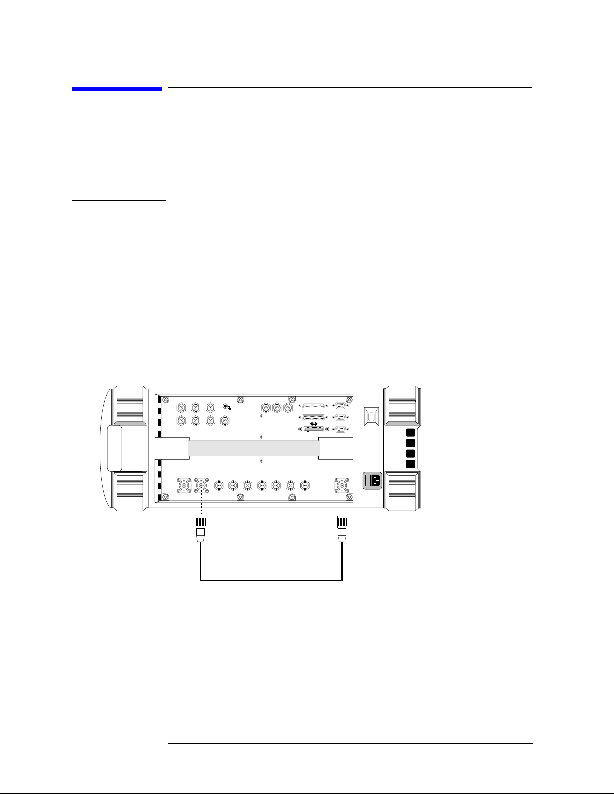
Connections for FM Carrier Loopback Test
Connect the Test Set as show n below.
Figure 1-1 FM Carrier Loopback Test Connections
AUDIO OUT
MODULATION
INPUT
ANT IN DUPLEX
HI LO
AUDIO
MONITOR
OUTPUT
AUDIO IN
EXT SCOPE
TRIG IN
16X
CHIP CLOCK
19.6608
MHz OUT
VIDEO
OUT
CHIP CLOCK
1.2288
MHz OUT
BASEBAND OUT
QI
SYNC IN
EVEN
FRAME
TRIG/QUALIN10 MHz
SECOND
CLOCK
IN
REF OUT
REF IN
PARALLEL PORT
PARALLEL PORT
SERIA PORT
SERIA PORT
SERIA PORT
RF IN/OUT
DUPLEX OUT
24 Chapter 1
RF IN/OUT
C:\Spk\AmpsGuide\Getstart.fm

Get Started with the Test Set
Getting Started with AMPS Test
Display an FM Carrier Signal (Loopback Test)
NOTE
Here are some guides for selecting screens and fields:
• Use the knob to move the cursor around the screen. Reverse video
boxes indicate fields that can be selected.
• To select a field on the screen, push the knob, or press the
•Use the
RF Gen, RF Anl
, and
Spec Anl
keys to access the RF
Enter
key.
GENERATOR, RF ANALYZER, and SPEC ANL screens.
• Selecting the title bar at the top of the screen displays a list of
screens that can be immediately accessed when selected .
Preparing the Test Set
1. Plug in the Test Set.
2. Turn on the Test Set (or press
Preset
ANALYZER screen will be displayed.
3. Press the
Inst
Config
key.
4. Select RF Display, and set the field to Freq.
5. Verify your connections. See “Connections for FM Carrier Loopback
Test” on page 24
if it is already on). The CDMA
Getting Started with AMPS
Test
NOTE
Generate an FM Carrier Signal
Refer to Figure 1-2.
1. Press
CDMA Gen
2. Select CW RF Path and set it to Bypass. This shuts off the IQ
modulation normally used for CDMA testing.
3. Press the
RF Gen
4. Select RF Gen Freq and use the keypad to set the frequency to
850.000 MHz.
5. Select Amplitude and set the amplitude to 0 dBm.
6. Select Output Port and verify that the port is set to Dupl.
7. T urn on FM modulati on by pos itioning the cur sor in the lower h alf of
the AFGen1 To field and pressing the
The default FM deviation is 2.9 kHz. The default FM rate is
1.0 kHz.
AF generators 1 and 2 are automatically turned off anytime you access
any of the CDMA screens (CDMA GENERATOR, CDMA ANALYZER,
to go to the CDMA GENERATOR screen.
key to go to the RF GENERATOR screen.
On/Off
key.
Chapter 1 25

Getting Started with AMPS Test
Display an FM Carrier Signal (Loopback Test)
CODE DOM). This prevents accidental addition of AM or FM when
generating a CDMA signal. If you accidentally access any of the CDMA
screens when testing an AMPS base station, any AM or FM you
specified on the RF GENERATOR screen will be turned off while on
that CDMA screen. Previously set AM and/or FM are automatically
turned back on when returning to the RF GENERATOR screen.
Figure 1-2 Setting Up the RF Generator
Enter 850 MHz
Enter 0 dBm
Tu rn on FM
Select DUPLEX
Analyzing an FM Carrier Signal
1. Press the
RF Anl
2. Select Tune Freq and use the keypad to set t he frequen cy to 850.000
MHz. Notice that the Frequency Error, TX Power, FM Deviation, and
AF Frequency for the signal are automatically displayed.
Figure 1-3 Default RF Analyzer Measurements
key to go to the RF ANALYZER screen.
26 Chapter 1
C:\Spk\AmpsGuide\Getstart.fm

Getting Started with AMPS Test
Display an FM Carrier Signal (Loopback Test)
3. Press the
Spec Anl
4. The signal is displayed.
5. Select Span and set it to 30.000 kHz to get a good view of the
modulated signal. See Figure 1-4.
Figure 1-4 FM Carrier Signal
key to go to the SPECTRUM ANALYZER screen.
Getting Started with AMPS
What to Do Next
Congratulations! You are now ready to begin testing your AMPS Base
Station. Proceed to Chapter 2 , “Testing AMPS Base Stations ,” on page
29.
Test
Chapter 1 27

Testing AMPS Base Stations
2
Testing AMPS Base Stations
Advanced Mobile Phone System (AMPS) base stations for cellular telephone
systems are basically contin u ous w av e (CW) FM v o ice transceivers with some
control and data signals for system operation. This chapter explains how to use
the Te st Set to manually test the RF and AF performance of the transmitter
and receiver portions of th e base station.
29

Testing AMPS Base Stations
AMPS Tests You Can Perform
AMPS Tests You Can Perform
The following tests are explained in this manual:
• “Transmitter Frequency Error/Offset and Power Test” on page 34.
• “Transmitter SAT Frequency and Deviation” on page 36.
• “Transmitter Data Deviation” on page 38.
• “Transmitter Maximum Voice Deviation” on page 40.
• “Receiver Sensitivity (SINAD)” on page 42.
• “Receiver Squelch Threshold” on page 45.
CAUTION
Transmitter power (TX Power) can only be measured through the Test
Set’s RF IN/OU T por t. Verify that the signal connected to this por t d oes
not exceed the limits print ed by the port.
If you hear a loud “warbling” sound from the Test Set, turn off your
transmitter immediately! This is the over-power alarm, warning that
instrument damage may occur. Caution: Turning the Test Set off at thi s
point does no t protect the internal circu i try. Also, re m o v i ng the cable
from the RF IN/OUT port without turning the transmitter off may
damage your transmitter or power amplifier (due to an impedance
mismatch).
The ANT IN port is only used for analyzing very low level signals
(≤60 mW). Never attempt to measure a transmitter’s power directly
using the ANT IN port, as instrument damage may occur.
The DUPLEX OUT port is only used to provide RF signals to the base
station’s receive port(s). It must not be connected to the base stations
transmit port or damage may oc cur to the Test Set.
30 Chapter 2
C:\Spk\AmpsGuide\Measure.fm

Testing AMPS Base Stations
What You Need to Know to Begin
What You Need to Know to Begin
You need to know how to control the base station and the basic
operation of the Test Set before you can test your base station.
Test Set operation includes how to change control settings, how to
navigate between control screens, and how to change the units used for
any measurement or setting. Test Set operation and feature
descriptions are included i n t h e Reference Guide.
Base station operation includes turning the transmitter on and off,
turning the SA T tone and data signals on and off, and knowing where to
connect test cables from th e Test Set to your base st at ion.
You also need to properly configure the Test Set for your test situation.
The following sections describe operations needed to simplify Test Set
operation and minimize measurement errors.
• Entering the known losses and/or gains in your test setup is
explained in “Compensating for Signal Losses and Gains in the Test
Setup” on page 33.
• Measuring the signal loss through cables and other devices is
explained in “Measuring Insertion Losses” on page 51.
• Choosing to enter your base station’s transmit and receive
frequencies by channel number or by discrete frequencies is
explained in “Using Channel Numbers to Set Analyzer and
Generator Frequencies” on page 69.
Testing AMPS Base Stations
Chapter 2 31

Testing AMPS Base Stations
Connecting the Test Set to Your Base Station
Connecting the Test Set to Your Base Station
The connections shown in Figure 2-1 indicate a “generic” base station
using a test interface for audio test signals and a laptop computer
running a control program to control the base station. A power splitter
is used for testing the receiver ports. Although this is a common setup
for performing tests, audio and RF connections to base st atio ns and the
ways base stations are controlled vary among manufacturers .
Figure 2-1 Connections Between the Test Set and the Base Station
Audio
Out
ANT IN
(≤60mW)
TX Mod RX Audio
Audio
In
DUPLEX OUT
(RF Gen Out)
AMPS BASE STATION
1
S
2
Power
Splitter
PARALLEL PORT
RF IN/OUT Port
(High Power RF Input)
side1_75.eps
Receive A
Receive B
Audio Test Signal
breakout port.
Local Control
Port
TX
32 Chapter 2
C:\Spk\AmpsGuide\Measure.fm

Testing AMPS Base Stations
Compensating for Signal Losses and Gains in the Test Setup
Compensating for Signal Losses and Gains in
the Test Setup
Signal losses or gains through cables, splitters, combiners, connectors,
amplifiers, or coaxial switches must be accounted for to ensure
measurement accuracy. These values are entered in the INST RUMENT
CONFIGURE screen (press the
Inst Config
Refer to “Measuring Insertion Losses” on page 51 for information about
measuring cable/system losses.
• Total losses/gains between the transmitter’s output and the Test
Set’s RF IN /OUT port are entered in the RF In/Out field. A negative
number (indicating a loss) causes the displayed TX power
measurement to be increased by the entered amount. A positive
number (indicating a gain) causes the RF analyzer to decrease the
displayed TX power measurement by the entered amount.
• Total losses between the Test Set’s DUPLEX OUT port and the base
station’s receive port(s) are entered in the Duplex Out field as a
negative number (such as −1.2). The RF Generator will
automatically increase its level out of the DUPLEX OUT port by the
value entered to compensate for the loss.
key).
Figure 2-2 Entering Test System Losses and Gains
Set the RF Level Offset
field to On
.
On/Off
LS AMPS
Enter the loss or gain
between each port and the
base station.
Testing AMPS Base Stations
Chapter 2 33

Testing AMPS Base Stations
Transmitter Frequency Error/Offset and Power Test
Transmitter Frequency Error/Offset and
Power Test
This test compares the measured c enter frequency of t he base station to
the AMPS channel standard. The resulting difference is the frequency
error (also called the frequency offset). The measurement can be
displayed in frequency units (Hz, kHz, MHz) or in parts per million
(ppm). Measurements are made with all modulation turned off.
The transmitter’s power can be measured any time the transmitter is
keyed, but may not be accurate unless all modulation is turned off.
Transmitter power may be specified by the manufacturer in units of
watts (W), milliwatts (mW), dBm, Volts (V), or millivolts (mV).
Prerequisites
The following conditions must be met before testing:
• The Test Set is turned on and Preset was pressed to establish a
known instrument state.
• You have configured the Test Set for channel or frequency tuning as
necessary (see “Using Channel Numbers to Set Analyzer and
Generator Frequencies” on page 69).
• You have specified any gains or losses in your test system (see
“Compensating for Signal Losses and Gains in the Test Setup” on
page 33).
Begin Testing
1. Turn off the base station’s RF transmitter. A transmitter can be
damaged if it is not transmitting into a specified load, such as an
antenna, power amplifier, duplexer, or power meter with a 50Ω input
impedance.
2. Verify that the transmitter’s rated RF power (or the level out of the
power amplifier if applicable) does not exceed the level printed next
to the Test Set’s RF IN/OUT connector.
3. Connect the transmitter’s RF output to the Test Set’s RF IN/OUT
port.
4. Turn off any modulation signals to the base station.
• Turn off the SAT tone.
• Turn off any data (digital) modulation signals.
• Turn off any audio (voice) modulation signals.
5. Press the
34 Chapter 2
RF Anl
key to access the RF ANALYZER screen.
C:\Spk\AmpsGuide\Measure.fm

Testing AMPS Base Stations
Transmitter Frequency Error/Offset and Power Test
6. Enter the transmitter’s RF Channel number.
7. Turn on the transmitter. The TX Freq Error and TX Power
measurements are displayed.
Note: Disregard any values shown for FM Deviation an d AF F req at
this time.
Figure 2-3 Transmitter Frequency Error and Power Test Results
Chapter 2 35
Testing AMPS Base Stations

Testing AMPS Base Stations
Transmitter SAT Frequency and Deviation
Transmitter SAT Frequency and Deviation
This test measures the transmitter’s Supervisory Audio Tone (SAT)
frequency and deviation in the absence of any other modulating signal.
Prerequisites
The following conditions must be met before testing:
❏ The Test Set is turned on and Preset was pressed to establish a
known instrument state.
• You have configured the Test Set for channel tuning (see “Using
Channel Numbers to Set Analyzer and Generator Frequencies” on
page 69).
• You have specified any gains or losses in your test system (see
“Compensating for Signal Losses and Gains in the Test Setup” on
page 33).
Test Procedure
1. Turn off the base station’s RF transmitter. A transmitter can be
damaged if it is not transmitting into a specified load, such as an
antenna, power amplifier, duplexer, or power meter with a 50Ω input
impedance.
2. Verify that the transmitter’s rated RF power (or the level out of the
power amplifier if applicable) does not exceed the level printed next
to the Test Set’s RF IN/OUT connector.
3. Connect the transmitter’s RF output to the Test Set’s RF IN/OUT
port.
4. Turn off the voice modulation to the transmitter.
5. Turn off data modulation to the transmitter.
6. Enable SAT transmission.
7. Press
8. Set the Filter 2 field to 6 kHz BPF. This helps remove unwanted
noise.
Shift, RF Anl
(AF Anl) to access the AF ANALYZER screen.
36 Chapter 2
C:\Spk\AmpsGuide\Measure.fm

Figure 2-4
Testing AMPS Base Stations
Transmitter SAT Frequency and Deviation
9. Press the
RF Anl
key to access the RF ANALYZER screen.
10.Enter the transmitter’s channel number in the RF Channel field.
11.Turn on the transmitter. The FM Deviation and AF Freq for the
SAT are displayed (as well as Frequency Error and TX Power).
Figure 2-5 SAT Fre quency and Deviation Test Results
Testing AMPS Base Stations
Chapter 2 37

Testing AMPS Base Stations
Transmitter Data Deviation
Transmitter Data Deviation
This test measures the transmitter’s digital data deviation in the
absence of any other modulating signal.
Prerequisites
The following conditions must be met before testing:
• The Test Set is turned on and Preset was pressed to establish a
known instrument state.
• You have configured the Test Set for channel tuning (see “Using
Channel Numbers to Set Analyzer and Generator Frequencies” on
page 69).
• You have specified any gains or losses in your test system (see
“Compensating for Signal Losses and Gains in the Test Setup” on
page 33).
Test Procedure
1. Turn off the base station’s RF transmitter. A transmitter can be
damaged if it is not transmitting into a specified load, such as an
antenna, power amplifier, duplexer, or power meter with a 50Ω input
impedance.
2. Verify that the transmitter’s rated RF power (or the level out of the
power amplifier if applicable) does not exceed the level indicated
next to the Test Set’s RF IN/OUT connec to r.
3. Connect the transmitter’s RF output to the Test Set’s RF IN/OUT
connector.
4. Turn off voice modulation to the transmitter.
5. Turn off the SAT to the transmitter.
6. Turn on the data modulation to the transmitter.
7. Press
8. Set Filter 1 to <20Hz HPF.
9. Set Filter 2 to >99kHz LP.
Shift, RF Anl
(AF Anl) to access the AF ANALYZER screen.
38 Chapter 2
C:\Spk\AmpsGuide\Measure.fm

Figure 2-6
<20Hz HPF
>99kHz LPF
Testing AMPS Base Stations
Transmitter Data Deviation
10.Press the
RF Anl
key to access the RF ANALYZER screen.
11.Enter the transmitter’s channel number in the RF Channel field.
12. Turn on the transmitter. The FM Deviation from the data is
displayed.
Figure 2-7 Data Deviation Test Results
Data Deviation
Testing AMPS Base Stations
Chapter 2 39

Testing AMPS Base Stations
Transmitter Maximum Voice Deviation
Transmitter Maximum Voice Deviation
This test measures the transmitter’s maximum FM Deviation by a
voice signal in the absence of any other modulation signal.
Prerequisites
The following conditions must be met before testing:
• The Test Set is turned on and Preset was pressed to establish a
known instrument state.
• You have configured the Test Set for channel tuning (see “Using
Channel Numbers to Set Analyzer and Generator Frequencies” on
page 69).
• You have specified any gains or losses in your test system (see
“Compensating for Signal Losses and Gains in the Test Setup” on
page 33).
Test Procedure
1. Turn off the base station’s RF transmitter. A transmitter can be
damaged if it is not transmitting into a specified load, such as an
antenna, power amplifier, duplexer, or power meter with a 50Ω input
impedance.
2. Verify that the transmitter’s rated RF power (or the level out of the
power amplifier if applicable) does not exceed the level indicated
next to the Test Set’s RF IN/OUT connec to r.
3. Connect the transmitter’s RF output to the Test Set’s RF IN/OUT
port.
4. Connect the transmitter’s audio modulation (voice) input to the Test
Set’s AUDIO OUT port.
5. Enable the transmitter’s audio (speech) modulation.
6. Turn off any modulation signals to the base station oth er tha n audio .
7. Press the
RF Anl
8. Enter the transmitter’s channel number in the RF Channel field.
9. Press the
RF Gen
key to access the RF ANALYZER screen.
key to access the RF GENERATOR screen.
10. Set the AFGen1 To field to Audio Out, and a level of 50 mV.
40 Chapter 2
C:\Spk\AmpsGuide\Measure.fm

Figure 2-8
Audio Out
Initially 50 mV
Testing AMPS Base Stations
Transmitter Maximum Voice Deviation
11. With the cursor still positioned in front of the level setting
(50 mV), press the
Incr Set
key and enter 20 dB using the keypad.
Figure 2-9
Increment
AFGen1
level by
20 dB.
12. Turn on the transmitter.
13. With the cursor still positioned in front of the level setting (50 mV)
press the up-arrow key once to increment the level by 20 dB.
14.Read the FM deviation.
15.Vary the AFGen1 Freq from 300 Hz to 3 kHz and observe the FM
deviation at each frequency. Deviation must not exceed the rated
system specification of ±12 kHz at any time.
Testing AMPS Base Stations
Watch
the FM
Deviation
while...
...chang
ing the
AFGen
1 Freq
from
300 Hz
16.Disconnect the cable to the transmitter’s audio modulation input
(connected in step 4) to reduce the chance of errors in your next
transmitte r te st .
Chapter 2 41

Testing AMPS Base Stations
Receiver Sensitivity (SINAD)
Receiver Sensitivity (SINAD)
This test measures the receiver’s ability to demodulate voice signals
from very low RF carrier levels.
Prerequisites
The following conditions must be met before testing:
• The Test Set is turned on and Preset was pressed to establish a
known instrument state.
• You have configured the Test Set for channel tuning (see “Using
Channel Numbers to Set Analyzer and Generator Frequencies” on
page 69).
• You have specified any gains or losses in your test system (see
“Compensating for Signal Losses and Gains in the Test Setup” on
page 33).
Test Procedure
1. Turn off the base station’s transmitter.
2. Turn the base station’s radio squelch, data, and SAT off.
3. Connect the base station receiver’s inputs to the Test Set’s DUPLEX
OUT port.
4. Connect the receive r’s audio output to the Test Set’s AUDIO IN
port(s). Unless the receiver’s audio out amplifier is not referenced to
chassis ground, you should only connect to the AUDIO IN - HI port.
For floating o u tput amplifiers, see the Agilent Technologies 8935
Series E6380A Reference Manual for information on using the
AUDIO IN - LO connection.
5. Press
6. Set the CW RF Path field to Bypass. This turns off the IQ modulation
used for CDMA tests.
CDMA Gen
to access the CDMA GENERATOR screen.
42 Chapter 2
C:\Spk\AmpsGuide\Measure.fm
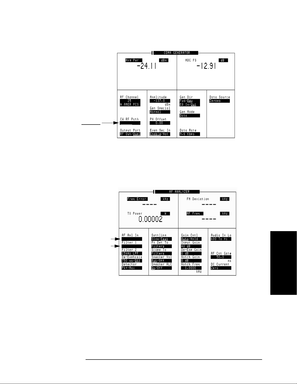
Figure 2-10
Testing AMPS Base Stations
Receiver Sensitivity (SINAD)
Set to Bypass.
Figure 2-11
Set to
Set to
Bypass/IQ
7. Press
SHIFT, RF Anl
(AF Anl) to access the AF ANALYZER screen.
8. Set the AF Anl In field to Audio In.
9. Set the Filter 1 field to C Message.
Audio In.
C Message.
Audio In
C Message
Testing AMPS Base Stations
10. Press the
RF Gen
key to access the RF GENERATOR screen.
11. Change the lower audio measurement to SINAD. This is done by
selecting the existing measurement and choosing SINAD from a list
of choices.
12. Set the AFGen1 To field to FM and turn it on (2.9 kHz) using the
On/Off
key.
13. Enter the transmitter’s channel number in the RF Channel field.
Chapter 2 43

Figure 2-12
Enter the
RF Channel number.
Set an initial
level of
−90 dBm.
Testing AMPS Base Stations
Receiver Sensitivity (SINAD)
14. Set an initial RF generator level in the Amplitude field. This value
depends on the sensitivity of the receiver; but −90 dBm should be a
good starting point. At this point you should be able to turn the Test
Set’s Volume knob clockwise and hear a 1 kHz tone from the Test
Set’s speaker.
Set to
SINA
Turn
on FM
modulation
15. Set the Amplitude field to increment in 1 dB units. To do this,
position the cursor in front of the Amplitude field, press the
Incr Set
key, and enter 1 dB using the keypad.
16. With the cursor front of the field, turn the knob to decrease the
Amplitude setting until the desired SINAD measurement is
displayed (commonly 12 dB). You should hear the 1 kHz tone get
noisy as you approach the 12 dB SINAD reading.
Figure 2-13 SINAD Tes t Res u lts
As you decrease the
RF generator
amplitude into your
receiver....
...the SINAD
reading goes
down and the
signal through
the Test Set’s
speaker gets
noisy.
44 Chapter 2
C:\Spk\AmpsGuide\Measure.fm

Testing AMPS Base Stations
Receiver Squelch Threshold
Receiver Squelch Threshold
This test determines the RF Signal level where the receiver squelches
(switches off) the audio output.
Prerequisites
The following conditions must be met before testing:
• The Test Set is turned on and PRESET was pressed to establish a
known instrument state.
• You have pressed the
state.
• You have configured the Test Set for channel tuning (see “Using
Channel Numbers to Set Analyzer and Generator Frequencies” on
page 69).
• You have specified any gains or losses in your test system (see
“Compensating for Signal Losses and Gains in the Test Setup” on
page 33).
Preset
key to establish a known instrument
Test Procedure
1. Turn off the base station’s transmitter.
2. Turn the base station’s data and SAT off.
3. Connect the base station receiver’s inputs to the Test Set’s DUPLEX
OUT port.
4. Connect the receive r’s audio output to the Test Set’s AUDIO IN
port(s). Unless the receiver’s audio out amplifier is not referenced to
chassis ground, you should only connect to the AUDIO IN - HI port.
For floating o u tput amplifiers, see the Agilent Technologies 8935
Series E6380A Reference Manual for information on using the
AUDIO IN - LO connection.
Testing AMPS Base Stations
5. Press
6. Set the CW RF Path field to Bypass. This turns off the IQ modulation
used for CDMA tests.
Chapter 2 45
CDMA Gen
to access the CDMA GENERATOR screen.

Figure 2-14
Testing AMPS Base Stations
Receiver Squelch Threshold
Set to Bypass.
Bypass/IQ
7. Press
SHIFT, RF Anl
(AF Anl) to access the AF ANALYZER screen.
8. Set the AF Anl In field to Audio In.
9. Press the
RF Gen
key to access the RF GENERATOR screen.
10.Set the AFGen1 To field to FM and set it to 8 kHz deviation.
11.Enter the transmitter’s channel number in the RF Channel field.
12.Set the Atten Hold field to On. The prevents the Test Set from
changing its internal attenuators during the test to prevent
erroneous squelch interruption.
13.Set an initial RF generator level in the Amplitude field. This value
depends on the sensitivity of the receiver; but −90 dBm should be a
good starting point. At this point you should be able to turn the Test
Set’s Volume knob clockwise and hear a 1 kHz tone from the Test
Set’s speaker.
46 Chapter 2
C:\Spk\AmpsGuide\Measure.fm

Figure 2-15
Enter the
RF channel
number.
Set a initial
level of
−90 dBm.
Set to On.
Testing AMPS Base Stations
Receiver Squelch Threshold
Turn
on FM
modulation
for the
8.00
On/off
RF
generator
14.Set the Amplitude field to increment in 1 dB units. To do this,
position the cursor in front of the Amplitude field, press the
Incr Set
key, and enter 1 dB using the keypad.
15.With the cursor in front of the Amplitude field, turn the knob
counterclockwise to decrease the Amplitude setting until the
received audio is no longer heard on the Test Set’s speaker (or until
the AC Level reading drops suddenly). The RF amplitude at which
the audio signal is no longer output is the squelch threshold.
Testing AMPS Base Stations
Chapter 2 47

3
Utility Procedures
This chapter contains procedures an d instructions that will help you
make the most efficient use of your Test Set.
Utility Procedures
49

Utility Procedures
Beeper
Beeper
The beeper notifies you when a message is displayed. Since a message
may be removed from the screen before you notice it, it is better to leave
the beeper on to alert you to errors during operation.
The beeper’s volume setting is retained when the instrument is turned
off.
Beeper Control
1. Press the
Inst Config
key to go to the INSTRUMENT CONFIGURE
screen.
2. Select Beeper.
3. Choose from Off, Quiet, or Loud.
50 Chapter 3
C:\Spk\AmpsGuide\Utilites.fm

Utility Procedures
Measuring Insertion Losses
Measuring Inse rtio n Losses
To make accurate power and receiver measurements, the signal loss
through the cables or other devices used in your test setup must be
known and entered into the Test Set’s INSTRUMENT CONFIGURE
screen to compensate for these losses.
Signal losses are measured using a built-in automated routine that
runs on the Test Set’s IBASIC controller. Los ses can be calibrated at a
discrete (single) frequency or over a frequency range. This is one
routine included in a set of utility procedures called the RF TOOLS.
During the test, a calibrated signal goes through two 6-dB
attentuators/pads (suc h as Mini-Circuits model NAT-6-60) and a short
type-N male-to-male cable to establish a known reference point. The
Test Set then prompts you to connect the device under test to measure
the additional loss through that device. (The pads and cable are not
part of the standard equ i pment shipped wi th th e Test Set.)
Figure 3-1 on page 51 shows how to load and run the RFTOOLS
routines and select the desired insertion loss test.
Figure 3-1 Loading and Running the Insertion Loss Test
1 Select
Select
2
3
Select
When the screen below appears.......
ROM.
RFTOOLS.
Run T e st.
...use the knob to move the cursor
and select either
Insertion L o ss
tion Loss
. When run, the test
Discrete Freq
or
Swept Inser-
prompts you to enter the nec essary
test frequency information and displays setup diagrams. Make the
indicated connections and follow
Utility Procedures
Chapter 3 51

Utility Procedures
Memory Cards
Memory Cards
The slot on the front of the Test Set is used for memory cards. The slot
is used for the following:
• Storage of save/recall registers
• Loading of software (either Agilent Technologies or self-written)
• Collecting data (only when using software)
• Upgrading firmware or software
Memory Cards and Initialization
There are several types of memory cards available, and the followin g
cards are used with the Test Set:
• SRAM: used for save/recall and data storage
• Flash ROM: used when upgrading firmware
• OTP (One-Time Programmable): used for Agilent Technologies
software
Flash ROM cannot be used for collecting data and Save/Recall.
Data cannot be loaded on Flash RAM and OTP cards with the T es t Set’ s
memory card slot.
SRAM can be initialized with the Test Set.
Initializing SRAM Cards for Save/Recall and Data Collection
1. Insert the SRAM card into the slot. If the card is uninitialized, a
message will appear at the top of the display.
2. Press
Shift
and
IO Confg
to display the I/O CONFIGURE screen.
3. Using the knob, locate the FORMAT CARD field.
4. Select the FORMAT CARD field. A prompt will appear at the top o f the
display. Pressing
will erase and initialize the card.
Yes
52 Chapter 3
C:\Spk\AmpsGuide\Utilites.fm

Oscilloscope
The built-in 50 kHz oscilloscope provides
• multiple triggering formats (internal and external)
• single-shot and pre-trigger viewing for single events
• full marker capability with automatic level and time readout
Time/division, volts/ division and vertical offset are displayed and can be
changed using the front-panel knob.
Input to the Oscilloscope (SCOPE) is provided from various sources
including direct inputs to the Audio Input and Modulation Input
connectors. Oscilloscope functio ns are accessed from the AF Anl and
SCOPE screens.
Figure 3-2 Inputs and Filters for the Oscilloscope
Utility Procedures
Oscilloscope
FM Demod
AM Demod
SSB Demod
AUDI O IN connecto r
Analog Modulati on In
connector
FM Mod
AM Mod
Audio O ut
Controlled by
AF Anl In
field
Input
Controlled by
Scope To
field
Filters
De-emp
Notch
Selecting the Oscilloscope’s Input
1. Press
2. Select the AF Anl Input field. A list of choices appears.
Shift
, then
RF Anl
(AF Anl) to select the AF ANALYZER screen.
To
Scope
To
Audio Monitor
Out connector
Chapter 3 53
Utility Procedures

Utility Procedures
Oscilloscope
3. Select the desired input to the scope:
• FM Demod for FM demodulated audio from input signals
connected to the RF IN/OUT or ANT IN connectors.
• AM Demod for AM demodulated audio from input signals
connected to the RF IN/OUT or ANT IN connectors.
• SSB Demod for SSB demodulated audio from input signa l s
connected to the RF IN/OUT or ANT IN connectors.
• Audio In for a s ignal connecte d to th e AUDIO IN connector.
• Ext Mod for a signal connected to the rear panel MODULATION
INPUT connector.
• FM Mod for the FM modulated audio from the RF generator
section.
• AM Mod for the AM modulated audio from the RF generator
section.
• Audio Out for the signal present at the AUDIO OUT connector.
4. The input to the oscilloscope is displayed on the SCOPE screen.
Selecting the Oscilloscope’s Filters
1. Press
2. Select the Scope To field. A list of choices should appear.
3. Select the desired filterin g f or the signa l :
• Input if you want no filtering (dc coupled)
• Filters to route the audio to the osc illoscope after pas sing through
filters 1 and 2. (ac coupled)
• De-emp to route the audio to the oscilloscope after passing
through filters 1 and 2, and the de-emphasis circuitry.(ac coupled)
• Notch to route the audio to the oscilloscope after passing through
Filters 1 and 2, the de-emphasis circuitry, and notch filter
circuitry. (ac coupled)
Shift
, then
RF Anl
(AF Anl) to select the AF ANALYZER screen.
54 Chapter 3
C:\Spk\AmpsGuide\Utilites.fm

Utility Procedures
Oscilloscope
Triggering the Oscilloscope
You can control following triggering features of the oscilloscope:
• Trigger: external or internal
• Automated or normal triggering
• Continuous or single shot triggering
• Trigger level
• Trigger delay
The oscilloscope is triggered using the Trigger menu. Select this menu
with the following procedure:
1. Press
Shift
, then
Spec Anl
(Scope) to go to the SCOPE screen.
2. Select the Controls field, then choose Trigger from the list of
choices.
Using the Marker
The marker is used to help you make measurements with the
oscilloscope. By repositioning the marker, you can measure the level
and time.
The Marker is controlled using t he Marker menu. Select this menu with
the following procedure:
1. Press
Shift
, then
Spec Anl
2. Select the Controls field, the choose Marker from the list of choices.
(Scope) to go to the SCOPE screen.
Chapter 3 55
Utility Procedures

Utility Procedures
Online Help
Online Help
The Test Set contains help screens which briefly identify the most
commonl y u sed features of the Test Set.
Access the help screens by pressing the
the Help Topic of interest.
Pressing the
key allows you to switch between the HELP screen
Prev
and the previous screen you had accessed. This is particularly useful
when you are following a procedure described in the HELP screen.
Help Screen Display
Figure 3-3 Help Screen Display
key. Use the knob to select
Help
56 Chapter 3
C:\Spk\AmpsGuide\Utilites.fm

Utility Procedures
Ports: GPIB, Serial and Parallel
Ports: GPIB, Serial and Parallel
There are three types of data ports on the Test Set: GPIB, Serial, and
Parallel. They each have specific purposes.
NOTE
Throughout this manual the terms GPIB and HP-IB may be used
interchangeably except in the case of specified command statements.
GPIB Port
This port is provided on the Test Set for IEEE 488.2 communications. I t
is used to control the Test Set with an external IBASIC controller, or to
control oth er GPIB equipped devices.
This port can be used with an external programming device when
writing programs, although it is also common to program the Test Set
using a serial port.
The default address of the GPIB port is 14. This is commonly used in
Agilent Technologies Instrument BASIC (IBASIC) programs. An
example command providing output to the port is
OUTPUT 714;”*RST”, w hich pres et s t he Test Set.
It has two modes, which correspond to modes useful when
programming the Test Set. Talk&Listn is the normal mode. Use
Control only when you need to control GPIB instruments external to
the Test Set.
Controlling the GPIB Port
1. Press
CONFIGURE screen.
2. Set the address of the GPIB port with the HP-IB Adrs field.
3. Use the Mode field to set the mode to either Talk&Listn or Control.
Shift
, then the
Inst Config
(I/O Config) key to display the I/O
Serial Ports
Three serial ports are available on the Test Set. SERIAL 9 is used for
printing, IBASIC control and data communications. SERIAL 10 is used
only for data communications from IBASIC. SERIAL 11 is reserved for
future use with special soft ware t hat enables remo te oper atio n through
a PC.
Configuring Serial Ports
All serial ports are configured via the I/O CONFIGURE screen. Baud
Rate, Parity, Data Length, Stop Length and Flow Control are all
configured in this screen.
Chapter 3 57
Utility Procedures

Utility Procedures
Ports: GPIB, Serial and Parallel
1. Press Shift, then I/O Config to go to the I/O CONFIGURE screen.
2. Select Serial Port to choose the port you want to configure.
3. Change the settings for the port as desired.
NOTE
Do not set Flow Cntl to Hardware on the I/O CONFIGURE screen for
the serial port until you have a device attached to the port that can
respond to the flow control communications.
Example: Assume you have a printer attached to Serial Port 9. Power is
off to the printer. Before y o u start to run any IBASIC softwar e (for
example, the RFTOOLS program), you must make sure the printer is
attached and power is on to the printer.
Additionally, port 9 can be configured for IBASIC control from this
screen. See “Configuring Se rial Port 9 for IBASIC Communications” on
page 59.
Using Serial Ports for Printing
Serial Port 9 is the only serial port that can be used for printing. See
“Printing” on page 60
1. If you want to change the serial port configuration, see “Configuring
Serial Port 9 for IBASIC Communications” on page 59 It is not
necessary t o change the Serial_9 In field.
2. Press Shift, then Printer Config to display the CONFIGURE
PRINTING screen.
3. Select Printer Port. Choose Serial 9 to direct the output to Serial
Port 9.
4. Press Print to print the screen.
58 Chapter 3
C:\Spk\AmpsGuide\Utilites.fm

Utility Procedures
Ports: GPIB, Serial and Parallel
Configuring Serial Port 9 for IBASIC Communications
The internal connection to Serial Port 9 is controlled in the I/O
CONFIGURE screen. The port has two purposes with IBASIC:
• Inst: Serial Port 9 is connected to a terminal (e.g. a PC running
Microsoft Windows HyperTerminal program). IBASIC
commands are input from the terminal and are used to control the
Test Set.
• IBASIC: Serial Port 9 is connected to a device that can communicate
with an IBASIC program already running inside the Test Set.
Typically used for input/output to a PC or other device.
1. Press Shift, then I/O Config to go to the I/O CONFIGURE screen.
2. Select Serial_9 In to toggle between Inst and IBASIC.
Parallel Ports
There are two parallel ports on the Test Set.
Parallel Port 15 is the only parallel port that can be us ed for printing. It
can be selected in the PRINTER CONFIGURATION screen.
Both parallel ports (Port 15 and Port 16) may be used for controlling a
base station. The port can be put in an input or an output mode. The
data is then written or read under IBASIC control. When in either of
these modes, the printing function on Parallel Port 15 is disabled.
Chapter 3 59
Utility Procedures

Utility Procedures
Printing
Printing
You can print from t he Test Set via Parallel Port 15, Serial Port 9, or the
GPIB port.
Note that data collection is not the same as printing. Data collection
can only be done from a software program.
Configuring the Test Set for Printing
1. Press
Shift
, then
(Printer Config) to display the PRINTER
Print
CONFIGURE screen.
2. Select the Model field and choose the printer that most closely
matches your printer.
3. Select the Printer Port field and choose the port you will connect
the printer to. If necessary, use the I/O CONFIGURE screen to set
up addresses and communication modes.
a. SERIAL PORT 9: This is the uppermost serial port. Conf iguration
defaults are 9600, none, 8, 1, Xon/Xoff.
b. GPIB: The GPIB address (HP-IB Adrs ) is set to printer address
701. Enter this number as 01. Set Mode to CONTROL. (The
default address 14 is reserved for a n external controller .)
c. PARALLEL PORT: There are two ports available. Port 15 (the
printer po rt) is the uppermost port.
4. Connect the proper cable to the connector you selected.
• SERIAL PORT: standard NULL MODEM cable.
• GPIB: GPIB cable (such as Agilent Technologies 10833B)
• PARALLEL PORT: parallel cable
5. Change the FF (form feed) and Lines/Page as needed.
Printing a Screen
1. Configure the Test Set for Printing.
2. Go to the screen you want to print.
3. Press the
(Optional).
4. Press the
5. To cancel the print, go to the PRINTER CONFIGURE screen and
select Abort Print.
60 Chapter 3
key if you want to te mporarily stop the measur ement.
Hold
key. Data will be sent to the printer.
Print
C:\Spk\AmpsGuide\Utilites.fm

Utility Procedures
Measuring Swept Return Loss
Measuring Swept Return Loss
This procedure measures the return loss (VSWR) of an antenna using
an IBASIC program that is in the Test Set’s memory. An external
directional bridge must be provided (such as an Eagle RLB 150X5
Option N5A or equivalent).
Press the
key to access the SOF TWARE MENU screen, and follow
Menu
the instructions illustrated on the following pages.
Figure 3-4 Loading and Running the Return Loss Program
Select
Select
Select
ROM.
RFTOOLS.
Run Test.
Use the knob to move the cursor and
select
Swept Return Loss
Chapter 3 61
.
(Next Page)
Utility Procedures

Utility Procedures
Measuring Swept Return Loss
Figure 3-5 Entering Swept Return Loss Measurement Information
Enter the
Start
and
Stop Frequency
values for the measurement.
The
Max expec ted loss
value is used
to determine the graphics scaling
when the m easurement is displayed.
The
DUPLEX OUT level
is adjustable to reduce the RF level used when
measuring the loss of sensitive devices,
and to minimize the amount of transmitted power during the test (if necessary).
Figure 3-6 Swept Return Loss Measurement Connections
62 Chapter 3
C:\Spk\AmpsGuide\Utilites.fm

Figure 3-7
T wo 6 dB attenuators (pads), two short
cables, and the return loss bridge are
used to establish a calibration reference
without the device under test
connected
. Press
Proceed
(
) to con-
k1
tinue.
As indicated by the NOTE on the
drawing, your return loss bridge may
be marked differently than shown.
Utility Procedures
Measuring Swept Return Loss
When measuring the swept return loss
of a transmission line that is not terminated at an antenna, terminate the
line into a 50Ω load.
After conne cting your device unde r
test, press
Proceed
(
) to make the
k1
measurement.
The plot in Figure 3-8 on page 64 is for a cellular band antenna, swept
from 800 MHz to 999 MHz. The plot (and the text above it) indicates
that the maximum return loss is at 885.4 MHz. This is the point where
the antenna is radiating the maximum amount of signal being fed into
it from the return loss bri dge, and ther efore the Test Set is receiving the
least amount of reflected (returned) energy back.
Device under test
Termination
Utility Procedures
Chapter 3 63

Utility Procedures
Measuring Swept Return Loss
Figure 3-8 Swept Return Loss Measurement Results
Proceed
to the run the
test again or to select a
different test.
Save Plot
to an
initialized writable PC
card. (See “Memory
Cards” on page 52.)
Perform a
Screen Dump
to print the sc re en to a
connected printer. (See
“Printing” on page 60.)
64 Chapter 3
C:\Spk\AmpsGuide\Utilites.fm

Utility Procedures
Tracking Generator
Tracking Generator
The tracking generator is typically used for measuring return loss and
insertion loss. It also allows for quick and accurate characterization of
filters, duplexers, combiners, and RF to IF conversions. Broadband RF
devices can be characterized with single sweeps due to the full-span
sweep capability to 1 GHz. The tracking generator also includes
amplitude and frequency offset . Output from t he tracking generator are
provided at either the RF IN/OUT or DUPLEX OUT connector.
Using the Tracking Generator
To measure return loss, “Measuring Swept Return Loss” on page 6 1. To
measure insertion loss, see “Measuring Insertion Losse s” on page 51.
Features of the tracking generator are listed below.
• Sweep: the start and stop frequencies of the sweep are determined
by the spectrum analyzer’s Main menu. The Span determines the
band, and Center Freq defines the midpoint of the sweep.
NOTE
• Offset Freq: sets the difference between the instantaneous
frequency of the tracking generator and the center frequency of the
spectrum analyzer. This value can be positive or negative.
• Amplitude: sets the amplitude of the signal.
• Norm/Invert: With Norm, the tracking generator sweeps from low to
high frequencies. With Invert, it sweeps from high to low
frequencies.
The offset function is useful when looking at frequency translating
devices, or anytime you need to sweep around a frequency while
analyzing another. During normal operation, off set is set to 0.00.
Chapter 3 65
Utility Procedures

Utility Procedures
Tracking Generator
Figure 3-9 Spectrum Analyzer with Tracking Generator Controls
Tracking
Generator
Controls
66 Chapter 3
C:\Spk\AmpsGuide\Utilites.fm

Utility Procedures
User Keys
User Keys
User keys instantly access inst rument s etting s wi thout using the knob.
You can use user keys to move quickly between fields on the same
screen, and to access field settings that are not normally available on
the screen you are using. When the user key is pressed, the cursor
instantly moves to, and selects, the assigned field.
Global user keys are used to access settings that are not available on
the current screen. Three global user keys are available: k1', k2', and
k3'. (To use one of these keys, press
Local user keys are used to move be tween sett ings on the s cree n that i s
currently displayed. Five local user keys are available for each screen:
k1, k2, k3, k4
, and k5. You can assign these keys yourself, or use the
factory preset assignments.
Displaying the Pre-assigned Local User Keys
, then k1, k2, or k3.)
Shift
1. Press the
2. Press the
3. Press
Enter
key.
Shift
(Assign) key.
k4
. Now the factory preset keys are displayed.
Assigning a Local User Key
1. Move the cursor to the field you want to assign to a user key.
2. Press the
3. Press the
4. Press the user key you want to assign to the field you chose. The
number of the user key will appear beside the field when you move
the cursor.
key.
Shift
(Assign) key.
k4
Chapter 3 67
Utility Procedures

Utility Procedures
User Keys
Assigning a Global User Key
1. Move the cursor to the field you want to assign to a user key.
2. Press the
3. Press the
4. Press the
5. Press the user key you want to assign to the field you chose (
or
). Global user keys are indicated as k1’, k2’ , and k3’ on the front
k3
key.
Shift
(Assign) key.
k4
key.
Shift
k1, k2
,
panel to indicate that they are shifted functions. The number of the
user key does not appear beside the field when using global user
keys.
To Release a User Key Assignment
Perform the same procedure fo r assigning a key, but instead of pressing
the
(Assign) key, press the
k4
(Release) key.
k5
68 Chapter 3
C:\Spk\AmpsGuide\Utilites.fm

Utility Procedures
Using Channel Numbers to Set Analyzer and Generator Frequencies
Using Channel Numbers to Set Analyzer and
Generator Frequencies
RF analyzer and RF generator frequencies can be entered by channel
number (the default setti n g ) or by discrete frequen ci e s (in MHz). The
RF Display field on the INSTRUMENT CONFIGURE screen controls
which way frequencies are entered. This screen is accessed by pressing
the
Inst Config
If the RF Display field is set to Chan for channel tuning, you also need
to set the RF Chan Std field to LS AMPS to tell the Test Set you are
testing Land (base) Station AMPS radios. This automatically sets the
correct 45 MHz frequency offset needed to generate reverse channel
signals and analyze forward channel signals for an AMPS base station.
If you do not know the channel number of your base station, but know
the transmit and receive frequencies, set the RF Display field to Freq.
You can then enter these frequencies directly for the R F generator and
RF analyzer during tests.
key.
Figure 3-10 Configuration to Use Channel Numbers for RF Generator and
Analyzer Settings
Set the
to turn on channel tuning.
Select the
play a list of system types.....
..and then select
AMPS base stations.
RF Display
RF Chan Std
field to
field to dis-
LS AMPS
Chan
for testing
Chapter 3 69
Utility Procedures

Utility Procedures
Using Channel Numbers to Set Analyzer and Generator Frequencies
RF Chan and Tune Freq Fields
NOTE
All of the test procedures in this document assume you are using
channel tuning. If you are using frequency tuning, enter the frequency
in the appropriate field(s).
When you use channel tuning, the RF ANALYZER and RF
GENERATOR screens displays an RF Channel field for entering the
channel to tune to or generate.
When you use frequency tuning, the RF ANALYZER screen replaces
the RF Channel field with the Tune Freq field for direct frequency
entry. The RF GENERATOR screen replaces the RF Channel field with
the RF Gen Freq field. For AMPS Base Station tests, remember that
there should always be a 45 MHz separation between the transmit and
receive fre q uencies (transmit frequ en cy is 45 MHz gre a ter than the
receive frequency).
70 Chapter 3
C:\Spk\AmpsGuide\Utilites.fm

Utility Procedures
Voltmeter
Voltmeter
A voltmeter is available in the Test Set, and can measure low level dc or
ac voltages. The input to the voltmeter is controlled by the AF Anl In
field in the AF ANALYZER screen.
CAUTION
Do not exceed the rated input to the Test Set for the DC Level and
AC Level measurements.
The connector best suited to making ac Level and dc Level
measurements is the AUDIO IN port.
Measuring AC Level and DC Level
1. Press
2. Select AF Anl In and choose Audio In.
3. Select Audio In Lo and choose Gnd. This sets the AUDIO IN LO
port to ground, which allows you to measure voltage at the AUDIO
IN HI port.
4. Attach a probe (f or example a 1:1 oscillo scope probe) to the AUDIO
IN HI connector.
5. AC Level is displayed. To change to DC Level, select the AF Freq
measurement and choose DC Level from the displayed list of
choices.
Shift
, then
RF Anl
(AF Anl) to go to the AF ANALYZER screen.
Chapter 3 71
Utility Procedures

Index
Index
A
AC level
measuring
AC volts
measuring
AF Anl Input
field
AF connections
Agilent Direct
Canada
Korea
Agilent sales of f i c es, 17
Agilent service c enters
AMPS Base Stations
manual testing
AMPS testing
AMPS tests
receiver sensitiv ity (SINAD)
receiver squelch threshold
transmitter data deviation
transmitter frequency
transmitter maximum voice
transmitter SAT frequency and
AMPS Tests listed, 30
analyzer and generator
frequencies
using channel numbe r s
Analyzing FM Carrier
ANT IN port
overpower
Antenna In field
ANTENNA IN port
losses
Assembly Leve l Rep ai r Manu al
calibration
assigning global user keys, 68
assigning local user keys
AUDIO IN port
AUDIO OUT port, 32
automatic operation
Available AMPS tests
B
Base Station connections
batteries
replacing
beeper, 50
C
cable losses
compensating
cables
for printing
, 71
, 71
, 53
, 32
, 21
, 21
, 17
, 29
, 20
error/offset and power
deviation
deviation
, 40
, 36
, 69
, 26
, 30
, 33
, 33
, 23
, 67
, 32
, 22
, 30
, 32
, 20
, 33
, 60
, 45
, 38
, 34
, 42
, 60
GPIB
Null Modem
calibration
Assembly Level Repa ir Manual
23
when you change a module, 23
call center
Europe
U.S., 21
Canada Agilent Direct
CD-ROM
documentation
Cell Band CDMA testing
change battery procedure
channel numbers
using, to set analyzer and
generator frequencies
congratulations, 27
connections
base station
FM Loopback test, 24
conventions used in his manual
D
Data Deviation test
DC level
measuring
DC volts
measuring
Displaying an FM Carrier
Duplex Out field
DUPLEX OUT port, 32
losses
overpower
E
entering test system losses and
gains
European Call Center
F
fields
selecting
FM Carrier
analyzing
displaying
FM Loopback test
FM Signal
displaying
FM signal
generating
frequencies
setting analyzer and generator
69
Frequency Error test
, 60
, 21
, 21
, 21
, 20
, 20
, 69
, 32
, 38
, 71
, 71
, 27
, 33
, 33
, 30
, 33
, 21
, 25
, 26
, 27
, 24
, 24
, 25
, 34
G
generating an FM signal
Getting Help, 21
,
Getting Started
global user keys
assigning, 68
releasing
H
help
how to get
online
screen display
hot keys
setting
GPIB communications
via the serial port
GPIB controller
internal to the Test Set
GPIB port
, 5
controlling
modes
I
IBASIC Programs
in this manual
INSTRUMENT CONFIGURE
K
k1, k2, k3, k4, k5
local user keys
k1’, k2’, k3’
global user keys
knob
using
Korea Agilent Direct
L
local user keys
assigning, 67
preassigned
releasing
Loopback Test, 24
M
manual operation
manual testing
AMPS base stations
manuals
maximizing measurement
,
measurem ent accuracy
maximizing
measurement port, 30
, 68
, 56
, 67
, 57
, 33
screen
, 25
, 68
, 11
accuracy
, 21
, 57
, 5
, 67
, 67
, 23
, 23
, 25
, 19
, 67
, 56
, 59
, 22
, 22
, 67
, 67
, 21
, 22
, 29
Index 73

Index
measuring path losses and gains,
31
memory cards, 52
modes of the Test Set
O
oscilloscope
features, 53
filters and inputs
marker
selecting the filters, 54
selecting the input
triggering
P
parallel port
input and output modes
ports 15 and 16
path losses, 33
measuring
PCMCIA card
Flash ROM, 52
initializing
OTP
SRAM, 52
PCS CDMA testing
port
GPIB
GPIB, serial, parallel
measuring AC or DC level
printing via the serial port, 58
serial
Power
measurement port
Power calibration/compensation
23
preassigned local user keys, 67
printing
and data collection
cables, 60
configuring the Test Set
FF (Form Feed)
how to print a screen, 60
GPIB
lines per page
parallel port, 60
ports
serial port 9
via the serial port, 58
probe
measuring AC or DC level
Product Description, 20
Programmer’s Guide
purchased software
, 53
, 55
, 55
, 31
, 52
, 52
, 52
, 57
, 57
, 60
, 60
, 60
, 60
, 22
, 53
, 53
, 59
, 59
, 20
, 57
, 71
, 30
, 60
, 60
, 60
, 60
, 71
, 22
, 22
R
RAM
backing up
read me first
Receiver Sens it ivit y te st
receiver squelch thresh ol d, 45
return loss
RF connections
RF In/Out field, 33
RF IN/OUT port
losses
measuring power, 30
overpower
RF Level Offset field
S
safety warnings and cautions
sales offices
SAT Deviation test
SAT Frequency test, 36
screens
selecting
serial port, 57
configuring
configuring for GPIB
port 9, configuring for GPIB
port 9, configuring for printing,
using for printing
signal losses and gains
compensating
SINAD test
software
,
manufacturer-specific
purchased
Spectrum Analyzer, 27
squelch threshold
SRAM card
initializing
systems
AMPS
CDMA, 20
PCS CDMA
T
temperature compensation
Pwr Zero
test interface connections
Test Set
documents included
what’s in the box
tips for sel ec t ing screens and
fields
TMO web site
, 20
, 31
, 61
, 32
, 33
, 30
, 21
, 25
, 57
communications
communications
58
, 33
, 42
, 22
, 52
, 20
, 20
, 23
, 25
, 21
, 32
, 45
, 21
, 33
, 36
, 58
, 59
, 59
, 21
, 42
, 22
, 32
, 9
tools contained in the Test Set
tracking generat or
controls display, 66
offset frequency
, 65
using
TX Power, 30
TX Power test
U
U.S. Call Center
user keys
Utility Procedures
V
Voice Deviation (max) test
voltmeter
volume
W
web site
what to do next
What’s Included with this Test
www.tmo.hp.com
, 67
global
, 67
local
releasing, 68
, 67
setting
, 71
Set
, 71
, 21
, 21
connector
controlling beeper
TMO
, 65
, 65
, 34
, 21
, 49
, 40
, 50
, 27
, 21
, 20
74 Index
 Loading...