

0.4 to 1000 MHz
1.4 to 2.0 GHz
• Cellular and PCS frequency coverage
• Analog and digital (IS-95B and
IS-2000 1XRTT) capabilities
• Built-in average power meter with
±7.5% accuracy
• Waveform quality r (rho), frequency
error, code domain power, timing,
and phase analysis
• Built-in AWGN source for calibrated
E
b/No
settings
• Dedicated, one-button user interface
keys
• Firmware upgradeable (via PCMCIA to
Flash Memory)
• Network equipment manufacturer (NEM)
base station specific automation
software increases measurement
repeatability and enhances
technician efficiency
The Agilent Technologies 8935 Series
E6380A AMPS/CDMA Cellular/PCS
base station test set is the next generation in CDMA base station test
equipment. The E6380A is a full
featured, one-box test set designed
to meet the needs of installation
teams, service providers, and network
equipment manufacturers.
Building on the success of our third
generation of base station test
equipment, the new test set heavily
incorporates feedback from PCS and
Cellular users. For example, the
E6380A utilizes a large, bright, easy-toread, electroluminescent display. A
convenient connector section on the
side of the test set allows unobtrusive,
out-of-the-way hook up, as well as
protects the connectors from damage.
A suitcase form factor provides better
portability.
The new “rugged design” includes a
reliable membrane keypad, a gasketed
display, and filtered airf low to resist
dirt and moisture. The unit’s enclosure
provides for stand up operation, and
helps protect itself from bumps and
shocks.
More importantly, the E6380A incorporates a user-friendly interface with
one-key measurement execution. This
interface, coupled with test set’s fast
measurement speed and automated
software for LGIC, Lucent, Nortel,
and Samsung base stations, results
in less off-line time and improved
system performance. Errors due to
test variability are reduced, and
measurement data can be output to
a printer or to the PCMCIA memory
card. Additionally, new features and
capabilities can be added to the
E6380A without returning the unit
to a service center. The test set’s
firmware is user upgradeable via a
PCMCIA card to Flash Memory.
To complete the CDMA parametric test
solution, Agilent also offers a technician training program to provide
install teams and service providers
with a comprehensive understanding
of base station test.
For more information about the
8935 series E6380A, refer to the
products link on our Web site at:
www.agilent.com/find/basesta
tions
Agilent E6380A
8935 Series AMPS/CDMA
Base Station Test Set
Data Sheet
Specifications describe the instrument’s warranted performance and are
valid over the entire operating/environmental range unless otherwise noted.
Supplemental Characteristics are intended to provide additional information useful in applying the instrument by giving typical, but non-warranted
performance parameters. These characteristics are shown in italics or
labeled as “typical,” “usable to,” or “nominal.”
CDMA Signal Generator Specifications
Frequency Range: 800 MHz to 1000 MHz, and 1.7 GHz to 2.0 GHz
(usable 4 to 200 MHz)
Output Level Range:
RF IN/OUT: –120 dBm to –40 dBm
DUPLEX OUT: –120 dBm to –10 dBm
Output Level Accuracy:
RF IN/OUT: ±1.5 dB, Typically ±1 dB
DUPLEX OUT: ±1.5 dB, Typically ±1 dB
Modes: Noise only, data only, and user selectable E
b/No
settings
CDMA Signal Generator RF Level Accuracy
(when in E
b/No
mode): Typically ±1.5 dB
Modulation
Reverse Link Source Modulation: OQPSK per TIA IS-95
Reverse Link Source Modulation Data: Internal data buffer,
Idle (all zeroes)
Forward Link Source Modulation: QPSK per TIA IS-95
Forward Link Source Modulation Data: Internal (Pilot Channel)
Residual rho (r): Better than 0.96,
Typically better than 0.98
Carrier Feedthrough: Typically <–35 dBc
Adjacent Channel Noise: Typically <–50 dBc measured in a
30 kHz BW filter relative to the total carrier power at f
c
±900 kHz
for output levels <–40 dBm at the RF IN/OUT connector (<–10 dBm
when using the DUPLEX OUT connector)
Data Buffer
Size/Length: 1800 frames per data rate set
Modes: Single, Continuous Looping, and Idle
Coding: IS-95 CDMA full rate reverse link channel coding, inter-
leaving and spreading
Long Code Mask: 42 zeros
Input Data: 9600 bps and 14.4 kbps entered via GPIB
Data Source: For each data rate set there are 300 frames of random data factory loaded, 1800 frames additional user definable
data which can be entered via GPIB.
AWGN Source
(Additive White Gaussian Noise)
Bandwidth: 2 MHz nominally
Distribution: Gaussian to >3 sigma
E
b/No
Resolution: 0.1 dB
E
b/No
Range: –5 to 25 dB
E
b/No
Accuracy: ±0.5 dB for Eb/Noof 5 to 20 dB, 25° C ±10° C,
Typically ±1 dB for E
b/No
of 0 to +5 dB and +20 dB to +25 dB
CDMA Analyzer Specifications
Average Power Measurement
Input Frequency Range: 30 MHz to 1000 MHz, and 1.7 to 2.0 GHz
Input Connector: RF IN/OUT only
Measurement Bandwidth: Provides an accurate measure of the
total power for signals within ±2 MHz of the operating frequency.
If other signals are present outside this frequency range, reduced
measurement accuracy will result.
Maximum Input Level: 15 W average for CDMA signals
Measurement Range:
4 mW to 15 W for f >100 MHz (+6 to +42 dBm)
4 mW to 1 W for f <100 MHz (+6 to +30 dBm)
Measurement Period: 0.25 ms to 26.66 ms
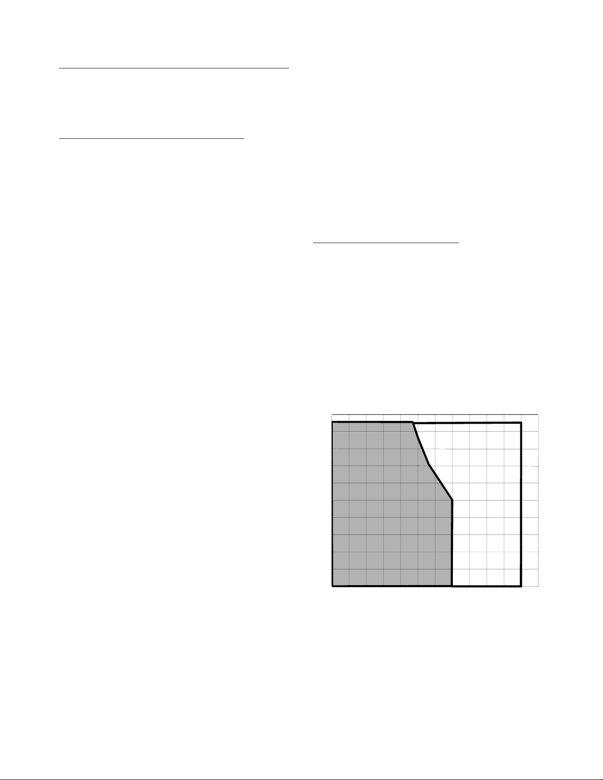
Figure 1. Average Power Measurement Accuracy
2
100%
80%
60%
40%
20%
0º C 10º C 20º C 30º C 40º C 50º C 60º C
32º F 50º F 68º F 86º F 104º F 122º F 140º F
Temperature
Relative Humidity
±(7.5% ±50 µW)
Typically ±5%
1.7 GHz≤f
c
≤2.0 GHz
±(12% ±50µW)
Typically 10%
f
c
≤1000 MHz
±(10% ±50 µW)
Typically ±7%

3
Channel Power Measurement (1.23 MHz)
Input Frequency Range: 800 MHz to 1000 MHz, and 1.7 to 2.0 GHz
Measurement Bandwidth: Measures the total average power in
a 1.23 MHz bandwidth centered on the selected frequency
Measurement Range:
RF IN/OUT: 0.1 µW to 15 W average (–40 to +42 dBm)
ANTENNA: Typically, 16 pW to 1.25 W average
(–78 to +4 dBm)
Measurement Accuracy (within five minutes of calibration (user
initiated) and within the 7.5% average power environmental window):
RF IN/OUT: 800 to 1000 MHz ± (0.75 dB ±25 nW)
at 4.95 MHz ± (1 dB ±40 nW)
ANTENNA: 800 to 1000 MHz typically, ± (0.75 dB ±6.5 pW)
at 4.95 MHz typically, ± (0.75 dB ±10 pW)
Measurement Period: 0.25 ms to 26.66 ms
Channel Power Measurement (30 kHz)
Input Frequency Range: 30 MHz to 1000 MHz, and 1.7 to 2.0 GHz
Measurement Bandwidth: Measures the total average power in
a 30 kHz bandwidth centered on the selected frequency
Measurement Range:
RF IN/OUT: 2.4 nW to 15 W average (–56 to +42 dBm)
ANTENNA: Typically, 0.39 pW to 1.25 W average
(–94 to +4 dBm)
Measurement Accuracy (within five minutes of calibration (user
initiated) and within the 7.5% average power environmental window):
RF IN/OUT: 30 to 1000 µHz ± (0.75 dB ±0.61 nW)
at 4.95 MHz ± (1 dB ±0.61 nW)
ANTENNA: At 4.95 MHz, 30 to 1000 MHz typically,
±(0.75 dB ±0.16 pW)
Measurement Period: 0.25 ms to 26.66 ms
Adjacent Channel Power
Frequency Range: 800 MHz to 1000 MHz and 1.7 GHz to 2.0 GHz
Adjacent Channel Power Bandwidth: 10 kHz to 1.23 MHz
(for BW >100 kHz, refer to ACP Filter in Reference Guide)
Adjacent Channel Power Offset: 100 kHz to 3 MHz
Measurement Range:
RF IN/OUT: 0.1 µW to 15 W average (–40 to +42 dBm)
ANTENNA: Typically 16 pW to 1.25 W average
(–78 to +4 dBm)
Measurement Accuracy:
RF IN/OUT:
Typically ±(0.75 dBc ±(2 x 10
–14
)(ACP BW)) W
ANTENNA
Typically ±(0.75 dBc ±(5.3 x 10
–18
)(ACP BW)) W
Waveform Quality Measurement
Frequency Range: 4 MHz to 1000 MHz, and 1.7 to 2.0 GHz
Input Level Range:
RF IN/OUT: –20 dBm to +42 dBm
ANTENNA: –58 dBm to +7 dBm
Measurement Period: 0.25 ms to 20 ms forward link 0.25 ms
to 10 ms reverse link
Measurement Range: 0.509 to 1.00
Rho Measurement Accuracy: Within ±0.005
Input Frequency Error Range: ±900 Hz
Frequency Error Measurement Accuracy: ±30 Hz using a
measurement interval >0.5 ms
Other Reported Parameters: Pilot Time Offset, Carrier Feedthrough
Error, Vector Magnitude, Amplitude Error, and Phase Error
Pilot Time Offset Measurement Accuracy: Typically <±500 nsec
from even second signal to start of PN sequence
Code Domain Analyzer
Frequency Range: 4 MHz to 1000 MHz, and 1.7 to 2.0 GHz
Input Connector: RF IN/OUT or ANT IN
Input Frequency Error Range: ±900 Hz
Input Level Range:
RF IN/OUT: –20 dBm to +42 dBm
ANTENNA: –58 dBm to +7 dBm
Code Domain Power Measurement
Displayed Dynamic Range: 40 dB
Relative Code Domain Power Accuracy: ±0.5 dB
(using a measurement interval >0.5 ms and Walsh channel power
>1% of channel power)
Absolute Code Domain Power Accuracy: ±1.25 dB
(using a measurement interval >0.5 ms and Walsh channel power
>1% of channel power)
Measurement Resolution: 0.01 dB
Carrier Frequency Offset Accuracy: ±30 Hz using a measurement
interval ≥0.5 ms
Pilot Time Offset Accuracy: Typically <500 nsec from even second signal to start of PN sequence
Other Reported Parameters: Estimated Rho, marker readings of
individual code power and noise
Code Domain Timing Measurement
1
(Pilot to Code Channel Time Tolerance)
Measurement Range: ±200 nsec
Measurement Accuracy: ±10 nsec using a measurement interval
of 12.5 ms
Measurement Resolution: 0.01 nsec
Code Domain Phase Measurement
1
(Pilot to Code Channel Phase Tolerance)
Measurement Range: ±200 mrad
1
IS-95B only

4
Measurement Accuracy: ±20 mrad using a measurement interval
of 12.5 ms
Measurement Resolution: 0.01 mrad
Signal Generator Specifications
RF Frequency
Range: 400 kHz to 1000 MHz, and 1.7 to 2.0 GHz
Accuracy and Stability: ±(0.065 Hz plus reference oscillator
accuracy)
Output
RF IN/OUT Connector
Level Range: –137 to –40 dBm into 50 W
Level Accuracy: ±1.0 dB (level >–127 dBm); if RF Analyzer
is also connected add ±0.1 dB
Typically ±1.0 dB for levels below –127 dBm
Reverse Power: 100 watts continuous, temperature <40° C,
75 W continuous, for temperature <55° C
SWR: <1.5:1
DUPLEX OUT Connector
Level Range: –125 to –10 dBm into 50 Ω
Maximum Power Output: +3 dBm
Level Accuracy: ±1.5 dB, Typically ±1.0 dB for all levels
Reverse Power: 200 mW max
SWR: <1.7:1
Supplemental Characteristics
Resolution: 0.1 dB
Spectral Purity
(For output levels of <–10 dBm at DUPLEX OUT or <–40 dBm
at RF IN/OUT)
Harmonics: <–25 dBc
Non-Harmonic Spurious (>5 kHz from carrier):
250 kHz ≤f
c
<249 MHz <–45 dBc
249 MHz ≤f
c
≤1000 MHz <–60 dBc
1700 MHz ≤f
c
≤2000 MHz <–55 dBc
Residual FM (rms, CCITT filter):
250 kHz ≤f
c
<249 MHz <7 Hz
249 MHz ≤f
c
<501 MHz <4 Hz
501 MHz ≤f
c
≤1000 MHz <7 Hz
1700 MHz ≤f
c
≤2000 MHz <14 Hz
Supplemental Characteristics
SSB Phase Noise (20 kHz offset):
f
c
<1 GHz <–116 dBc/Hz
1.7 GHz < f
c
<2.0 GHz <–90 dBc/Hz
FM
FM Deviation Maximum (For rates >25 Hz):
400 kHz <f
c
<249 MHz 100 kHz
249 MHz <f
c
<501 MHz 50 kHz
501 MHz <f
c
<1000 MHz 100 kHz
1.7 GHz <f
c
<2.0 GHz 100 kHz
[FM not specified for (f
c
minus FM dev) <400 kHz]
FM Rate (1 kHz reference):
Internal: DC to 25 kHz (1 dB BW )
External: AC Coupled: 20 to 75 kHz (typically 3 dB BW)
DC Coupled: DC to 75 kHz (typically 3 dB BW)
FM Accuracy (1 kHz rate):
<10 kHz dev: ±3.5% of setting ±50 Hz
>10 kHz dev: ±3.5% of setting ±500 Hz
FM Distortion (THD + noise, in a 0.3 to 3 kHz BW):
<0.5% at >3 kHz dev. and 1 kHz rate, f
c
<1000 MHz
<1.0% at >3 kHz dev. and 1 kHz rate, 1.7 GHz < f
c
<2.0 GHz
Center Frequency Accuracy in DC FM mode
(external source impedance <1k Ω):
±500 Hz (after DC FM zero), typically ±50 Hz
Supplemental Characteristics
Ext. Mod. Input Impedance: 600 Ω nominal
Resolution:
50 Hz for <10 kHz deviation
500 Hz for >10 kHz deviation
AM
Supplemental Characteristics
AM Depth: 0 to 60%
External Modulation Input Impedance:
600 Ω nominal
RF Analyzer Measurements
SWR:
RF IN/OUT Port: < 1.5: 1
ANT IN Port: <1.6:1, except <1.8:1 for 0 dB
attenuation in 1.7 to 2.0 GHz band
RF Frequency Measurements
Measurement Range: 400 kHz to 1 GHz, 1.7 to 2.0 GHz
Level Range:
RF IN/OUT:
1 mW to 100 watts continuous, temp. <40° C,
75 W continuous, for temperatures <55° C
ANT IN: –38 dBm to +15 dBm
Accuracy: ±1 Hz plus timebase accuracy
Supplemental Characteristics
Frequency Resolution: 1 Hz (The user must set the instrument
within 15 kHz of the signal under test)

RF Power Measurements
Frequency Range: 30 MHz to 1 GHz, 1.7 to 2.0 GHz
Figure 2. Accuracy
Measurement Range RF IN/OUT:
2
100 MHz <fc<2.0 GHz:
4 mW to 100 W continuous, temperatures <40° C,
75 W continuous, for temperatures <55° C
30 MHz <f
c
<100 MHz: 4 mW to 1 W continuous
Supplemental Characteristics
Resolution: 3 digits (Example: Resolution of 10 mW for powers
<10 W and >1 W)
FM Measurement
Frequency Range: 5 MHz to 1 GHz (usable to 400 kHz),
and 1.7 to 2.0 GHz
Deviation: 20 Hz to 75 kHz
Sensitivity: 4 µV for 12 dB SINAD, (30 kHz IF BW,
high sensitivity mode, 0.3 to 3 kHz BW)
Typically: < 2 µV (12 dB SINAD, f
c
>10 MHz)
Accuracy: ±4% of reading plus residual FM and noise contribution
(20 Hz to 25 kHz rates, deviation < 25 kHz, 230 kHz IF BW)
Bandwidth (3 dB): 20 Hz to 70 kHz
THD + Noise: <1% rms, (for deviation >5 kHz and at a rate of
1 kHz in a 0.3 to 3 kHz BW, 230 kHz IF BW)
Input Level Range for Specified Accuracy:
–6 to +50 dBm at RF IN/OUT
–44 to +12 dBm at ANTENNA IN
Residual FM and Noise (0.3 to 3 kHz, rms):
<7 Hz, for f
c
<1000 MHz
<14 Hz, for 1.7 <f
c
<2.0 GHz
Supplemental Characteristics
Resolution: 1 Hz, f <10 kHz ; 10 Hz, f >10 kHz
AM Measurement
Frequency Range: 10 MHz to 1 GHz (usable to 400 kHz), 1.7 to 2.0 GHz
Depth: 0 to 95%
Input Level Range (levels in PEP):
–6 to +52 dBm at RF IN/OUT
–44 to +14 dBm at ANTENNA IN
Supplemental Characteristics
Accuracy: ±5% of reading ±1.5 % AM, ( 50 Hz to 10 kHz rates,
modulation <80%)
THD + Noise: <2% rms for modulation <80% AM,
(at 1 kHz rate in a 0.3 to 3 kHz bandwidth)
Residual AM: <0.2% in a 0.3 to 3 kHz bandwidth
Resolution: 0.1%
Spectrum Analyzer Specifications
Frequency Range: 400 kHz to 1 GHz, 1.4 to 2.0 GHz
Frequency Span/Resolution Bandwidth (coupled):
Span Bandwidth
<50 kHz 300 Hz
<200 kHz 1 kHz
<1.5 MHz 3 kHz
<18 MHz 30 kHz
>18 MHz 300 kHz
Span Capability:
3
Full span capability 1 GHz
Display: Log with 1, 2, and 10 dB per division
Display Range: 80 dB or 8 divisions
Reference Level Range: +50 to –50 dBm
Residual Responses: <–70 dBm (ANT IN port, no input signal,
0 dB attenuation)
Image rejection: >50 dB
Supplemental Characteristics
Non-harmonic Spurious Responses:
>65 dB down (for input signals >50 MHz, <–30 dBm),
>55 dB down (for input signals <50 MHz, <–30 dB)
Log Scale Linearity: ±2 dB, (for input levels <–30 dBm within 6
divisions of reference level
Displayed Average Noise Level: <–114 dBm, for <50 kHz span,
–50 dBm reference level
Level Accuracy (at center frequency and within 1 division of
reference level): ±2.5 dB
Tracking Generator Specifications
Tracking Generator Frequency Range: 400 kHz to 1 GHz,
1.7 to 2.0 GHz
Frequency Offset: Frequency span endpoints ± frequency offset
cannot be <400 kHz or >1 GHz in the 1 GHz band and cannot be
<1.7 GHz or >2.0 GHz in the 2 GHz band
Output Level Range: Same as signal generator, page 4
Sweep Modes: Normal and inverted
2. To achieve the specified accuracy when measuring power at the RF IN/OUT port,
the internal signal generator level must be 60 dB below the measured power or
less than –20 dBm at the Duplex port.
3. Center frequency must be <1.0 GHz or between 1.7 to 2.0 GHz
5
100%
80%
60%
40%
20%
0º C 10º C 20º C 30º C 40º C 50º C 60º C
32º F 50º C 68º C 86º C 104º C 122º C 140º C
Temperature
Relative Humidity
±(7.5% ±50 µW)
Typically ±5%
1.7 GHz≤f
c
≤2.0 GHz
±(12% ±50µW)
Typically 10%
f
c
≤1000 MHz
±(10% ±50 µW)
Typically ±7%

6
Oscilloscope Specifications
Frequency Range: 2 Hz to 50 kHz (3 dB BW)
Scale/Division: 10 mV to 10 V
Amplitude Accuracy: ±1.5 % of reading ±0.1 division
(20 Hz to 10 kHz)
Time/Division: 10 µsec to 100 msec
Trigger Delay: 20 µsec to 3.2 seconds
Supplemental Characteristics
3 dB Bandwidth: Typically >100 kHz
Internal DC Offset: <0.1 div (>50 µV/div sensitivity)
AF Analyzer Specifications
Frequency Measurement
Measurement Range: 20 Hz to 400 kHz
Accuracy: ±0.02% plus 0.1 Hz plus timebase accuracy
External Input: 20 mV to 30 Vrms
Supplemental Characteristics
Resolution:
0.01 Hz, f <10 kHz; 0.1 Hz, f <100 kHz;
and 1 Hz for f >100 kHz
AC Voltage Measurement
Measurement Range: 0 to 30 Vrms
Accuracy: ± 3% of reading + residual noise (20 Hz to 15 kHz,
inputs >1 mV)
Residual Noise: 150 µV (15 kHz LPF) 450 µV (>99 kHz LPF)
Supplemental Characteristics
3 dB Bandwidth: Typically 2 Hz to 100 kHz
Nominal Input Impedance: Switchable between 1 MΩ in parallel
with 95 pF or 600 Ω floating
Minimum Resolution: 4 digits for inputs >100 mV;
3 digits for inputs <100 mV
DC Voltage Measurement
Voltage Range: 100 mV to 42 V
Accuracy: ±1.0% of reading ±45 mV
DC offset: ±25 mV
Supplemental Characteristics
Resolution: 1 mV
Distortion Measurement
Frequency Range: 300 Hz to 10 kHz ±5%
Input Level Range: 30 mV to 30 Vrms
Display Range: 0.1% to 100 %
Accuracy: ±1 dB (0.5 to 100% distortion) for tones from 300 to
1500 Hz measured with the 15 kHz LPF
±1.5 dB (1.5 to 100% distortion) for tones from 300 Hz to 10 kHz
measured with the >99 kHz LPF
Residual THD + Noise: –60 dB or 150 µV whichever is greater,
for tones from 300 to 1500 Hz measured with the 15 kHz LPF
Typically –52 dB or 450 µV, whichever is greater, for tones from
300 Hz to 10 kHz measured with >99 kHz LPF
Supplemental Characteristics
Resolution: 0.1 % distortion
SINAD Measurement
Frequency Range: 300 Hz to 10 kHz, ±5%
Input Level Range: 30 mV to 30 Vrms
Display Range: 0 to 60 dB
Accuracy: ±1 dB (0 to 46 dB SINAD) for tones from 300 to
1500 Hz measured with the 15 kHz LPF
±1.5 dB (0 to 36 dB SINAD) for tones from 300 Hz to 10 kHz
measured with the >99 kHz LPF
Residual THD + Noise: –60 dB or 150 µV, whichever is greater,
for tones from 300 to 1500 Hz measured with the 15 kHz LPF
Typically –52 dB or 450 µV, whichever is greater, for tones from
300 Hz to 10 kHz measured with >99 kHz LPF
Supplemental Characteristics
Resolution: 0.01 dB
Audio Filters
Standard Fixed: <20 Hz HPF, 50 Hz HPF, 300 Hz HPF, 300 Hz LPF,
3 kHz LPF, 15 kHz LPF, >99 kHz LPF, 750 µsec de-emphasis,
6 kHz BPF, and C-Message
Variable Frequency Notch Filter:
Frequency Range: 300 Hz to 10 kHz
Notch Depth: >60 dB
Notch Width: Typically ±5%
Audio Detectors
RMS, Pk+, Pk–, Pk+hold, Pk–hold, Pk±/2, Pk±/2 hold, Pk ± max,
and Pk ± max hold.
Signaling
Capability for Generating and Analyzing the Following Formats:
CDCSS, DTMF, 1 Tone, 2 Tone, 5/6 Tone, Sequential, RPC1
(POCSAG), EIA, CCITT, CCIR, ZVEI, DZVEI, GOLAY, EEA, AMPS,
NAMPS, TACS, NTACS, NMT-450, NMT-900, LTR, EDACS, and
MPT 1327.
Function Generator Waveforms: Sine, square, ramp, triangle, dc,
white Gaussian and white uniform noise
Function Generator Frequency Range and Level: Same as audio
source

7
Audio Source Specifications
(Applicable to both internal sources)
Frequency
Range: DC to 25 kHz
Accuracy: 0.025% of setting
Supplemental Characteristics
Minimum Resolution: 0.1 Hz
Output Level
Range: 0.1 mV to 4 Vrms
Maximum Output Current: 20 mA peak
Output Impedance: < 1.5 Ω (1 kHz)
Accuracy: ±2% of setting plus step size
Residual Distortion: 0.125%, (THD plus noise, for amplitudes
>200 mVrms), for tones 20 Hz to 25 kHz measured in an
80 kHz BW
Supplemental Characteristics
Step Size:
Level <0.01V: ±50 µV pk
Level <0.1V: ±0.5 mV pk
Level <1V: ±5 mV pk
Level <10V: ±50 mV pk
Offset in DC Coupled Mode: <50 mV
RF Tools Measurements
(All specifications are typical and assume the use of the E6554A
RF Tools Accessories Kit)
Swept Insertion Loss Test:
Frequency Range: 0.4 to 1000 MHz, 1.7 to 2.0 GHz
Swept Signal Level: –54 dBm to +10 dBm
Insertion Loss Accuracy: ±0.75 dB
Swept Gain Test:
Frequency Range: 0.4 to 1000 MHz, 1.7 to 2.0 GHz
Swept Signal Level: –54 dBm to +10 dBm
Swept Return Loss Test:
Frequency Range: 0.4 to 1000 MHz, 1.7 to 2.0 GHz
Swept Signal Level: –54 dBm to +10 dBm
Swept Return Loss Accuracy: ±2 dB ±10% of reading,
for readings between 0 dB and 30 dB
Cable Fault Test:
Cable Types Tested: Heliax, RG, Custom
Cable Length Range: 0 to 1000 feet, 0 to 300 meters
Distance Accuracy: ±5% of the cable length value entered
by the user
Precision Calibration
Option 012 / R12 Time Offset Precision Calibration
Cal factor accuracy +/- 21 nsec
General Specifications
Dimensions (H x W x D): 8.75 x 15.6 x 21.5 inches
(222 x 396 x 546 mm)
Weight: 49 lbs. (22 kgs)
Operating Temperature: 0° C to +55° C
Operating Humidity: <95% relative humidity, 0° C to 40° C
Storage Temperature: –40° C to +70° C
Power: 100 Vac to 240 Vac ±10%, 50 to 60 Hz, nominally 350 VA
Display Size: 9.7 cm x 13 cm, electroluminescent (EL)
Calibration Interval: Two years
Operating Altitude: 4500 m max
Supplemental Characteristics
Minimum Frequency Resolution: 1 Hz
Switching Speed: <150 ms to be within 100 Hz of the carrier
frequency
Leakage: At RF generator output levels <–40 dBm, typical
radiated leakage is <10 µV induced in a resonant dipole antenna
25 mm (1 inch) away from any surface. Spurious leakage levels
are typically <10 µV in a resonant dipole antenna 25 mm (1 inch)
away from any surface.
Side Panel Connectors
External Ref In:
Input Frequencies: 1, 2, 5, 10, and 15 MHz;
1x, 2x, 4x, 8x, and 16x chip clock
Input Level: >0.15 Vrms
10 MHz Ref Out:
Output Frequency: 10 MHz
Output Level: >0.5 Vrms
Waveform: Sine wave
Chip Clock - 1.2288 MHz Out:
Output Level: Nominally, TTL with 50 Ω impedance
Waveform: Square wave with ~50% duty cycle
16X Chip Clock - 19.6608 MHz Out:
Output Level: Nominally, TTL with 50 Ω impedance
Waveform: Square wave with ~50% duty cycle
Frame Clock Out:
Clock Selections: 20 ms, 26.67 ms, 80 ms, or 2.00 s
Output: ~800 ns pulse, 1.5 Vpk into 50 Ω
Even Second - Sync In: A positive edge starts CDMA frame
clocks and Pilot PN sequence generation
Trig Qualifier In: A rising edge is used to start the trigger
delay timer
Audio Out: Provides output signals from the audio frequency
generators
Audio In: A switchable (1 MΩ and 600 Ω) inputs to the
AF analyzer
Analog Modulation In: Provides an external modulation
(AM or FM) connection for the RF Generator
Scope Monitor Out: External output from the AF analyzer
External Scope Trig In: Provides an external trigger input
for the oscilloscope
Video Out: Provides a signal for any standard PAL monitor
(15.7 kHz scan rate)
Data In: Provides a data input to the CDMA generator
Base-band Out (I and Q): Provides buffered versions of
the I and Q drive signals from the CDMA generator

Remote Programming
GPIB: Implementation of IEEE Standard 488.2
Functions Implemented: SH1, AH1, T6, L4, SR1, RL1, LE0, TE0, PP0, DC1, DT1, C4, C11, E2
RS-232: Three serial ports through DB-9 connectors used for serial data in and out
Rates: 150, 300, 600, 1200, 2400, 4800, 9600, 19200, 38400, 57600, and 115200 Baud
Standard User Memory, RAM
Approximately 928 Kbytes of RAM are available for nonvolatile save/recall of
settings. This typically will allow you to save >500 sets of instrument settings;
depending on the type of information saved.
Reference Oscillator
Standard TCXO: (Temperature controlled crystal oscillator)
Temperature: 0.1 ppm (0° C to +55° C)
Aging: <0.5 ppm/year (<1 ppm in first year)
Warm-up Time: <15 minutes to be within ±0.1 ppm of final frequency
Option 1D5 High Stability Reference: (Oven controlled crystal oscillator)
Temperature: 0.05 ppm (0° C to +55° C)
Aging: <0.5 ppm/year (<1 ppm in first year)
Warm-up Time: <15 minutes to be within ±0.1 ppm of final frequency
Memory Card Specifications
Card Compatibility: Single industry standard PCMCIA slot accepts Type I or Type II
SRAM and ROM memory cards
Storage Capability: Allows for the storage and retrieval of IBASIC program
parameter and results data, input of new calibration data, and long-term storage
of Store/Recall information
Firmware Upgrades: Accepts PCMCIA flash memory cards (4 Mbytes) to
allow automatic loading of new firmware from the front panel. Upgrade time
is about eight minutes
Ordering Number
8935 Series CDMA Cellular/PCS Base Station Test Set ordering number: E6380A
For More Product Information
For more information visit our Web site: www.agilent.com/find/basestations
Agilent Technologies’ Test and Measurement
Support, Services, and Assistance
Agilent Technologies aims to maximize the value
you receive, while minimizing your risk and problems. We strive to ensure that you get the test
and measurement capabilities you paid for and
obtain the support you need. Our extensive support resources and services can help you choose
the right Agilent products for your applications
and apply them successfully. Every instrument
and system we sell has a global warranty.
Support is available for at least five years beyond
the production life of the product. Two concepts
underlie Agilent's overall support policy: "Our
Promise" and "Your Advantage."
Our Promise
Our Promise means your Agilent test and measurement equipment will meet its advertised performance and functionality. When you are choosing new equipment, we will help you with product
information, including realistic performance specifications and practical recommendations from
experienced test engineers. When you use
Agilent equipment, we can verify that it works
properly, help with product operation, and provide
basic measurement assistance for the use of
specified capabilities, at no extra cost upon
request. Many self-help tools are available.
Your Advantage
Your Advantage means that Agilent offers a wide
range of additional expert test and measurement
services, which you can purchase according to
your unique technical and business needs. Solve
problems efficiently and gain a competitive edge
by contracting with us for calibration, extra-cost
upgrades, out-of-warranty repairs, and on-site
education and training, as well as design, system
integration, project management, and other professional engineering services. Experienced
Agilent engineers and technicians worldwide can
help you maximize your productivity, optimize the
return on investment of your Agilent instruments
and systems, and obtain dependable measurement accuracy for the life of those products.
By internet, phone, or fax, get assistance with
all your test & measurement needs
Online assistance:
www.agilent.com/find/assist
Phone or Fax
United States:
(tel) 1 800 452 4844
Canada:
(tel) 1 877 894 4414
(fax) (905) 282-6495
China:
(tel) 800-810-0189
(fax) 1-0800-650-0121
Europe:
(tel) (31 20) 547 2323
(fax) (31 20) 547 2390
Japan:
(tel) (81) 426 56 7832
(fax) (81) 426 56 7840
Product specifications and descriptions in this
document subject to change without notice.
Copyright © 2001 Agilent Technologies
Printed in U.S.A. August 14, 2001
5968-3798E
Korea:
(tel) (82-2) 2004-5004
(fax) (82-2) 2004-5115
Latin America:
(tel) (305) 269 7500
(fax) (305) 269 7599
Taiwan:
(tel) 080-004-7866
(fax) (886-2) 2545-6723
Other Asia
Pacific Countries:
(tel) (65) 375-8100
(fax) (65) 836-0252
Email:
tm_asia@agilent.com
 Loading...