

Page 1

HP 75000 Series C
VXI Pentium® Controller
Hardware Installation and Configuration Guide
HP E623xA HP VXI Pentium Controllers
Manual Part Number: E6232-90001
Printed in U.S.A. E0897
Page 2

Page 3

Contents
Warranty ................................................ ......... ......... ......... ......... ......... ......... ......... ........3
Safety Symbols.............................................................................................................4
WARNINGS.................................................................................................................4
Declaration of Conformity............................................................................................5
Chapter 1
Introduction ....................................................................................................................7
About this Manual ........................................................................................................7
Overview.......................................................................................................................9
Major Components ..............................................................................................10
Front Panel ..........................................................................................................11
Where to Go Next.......................................................................................................12
Chapter 2
Installing and Configuring the Hardware .................................................................13
About this Chapter.............................................................................. ......... ......... ......13
Before You Begin......................................................................................................13
Verify the Product Package .................................................................................14
Check the Installation Location ...........................................................................15
Gather the Equipment Needed ............................................................................15
Installing the Controller in the VXI Card Cage..........................................................16
Installing Other Interfaces .................................................................................... ......16
Connecting the Peripherals.........................................................................................18
Powering Up the Controller........................................................................................19
Pre-power Checklist ............................................................................................19
Turning on the Power ..........................................................................................19
Setting the Controller’s Internal Clock ...............................................................19
Customizing the Controller’s BIOS............................................................................20
Where to Go Next.......................................................................................................21
Software Installation and Configuration ............................................................21
Chapter 3
Using the BIOS Setup Utility ......................................................................................23
About this Chapter.............................................................................. ......... ......... ......23
Accessing BIOS Setup................................................................................................23
Navigating BIOS Setup Menus...................................................................................23
Main BIOS Setup Menu .............................................................................................24
IDE Adapter 0 Sub-Menus ..................................................................................25
Memory Cache Sub-Menu ..................................................................................27
Memory Shadow Sub-Menu ...............................................................................28
Boot Sequence Sub-Menu ...................................................................................29
Keyboard Features Sub-Menu .............................................................................30
Advanced Menu.........................................................................................................31
Integrated Peripherals Sub-Menu ........................................................................32
Advanced Chipset Control Sub-Menu ................................................................33
Power Management Menu.........................................................................................35
EXM Menu................................................................................................................38
Exit Menu ..................................................................................................................39
Contents 1
Page 4

Chapter 4
Troubleshooting ........................................................................................................... 41
About this Chapter.............................................................................. ......... ......... ......41
Abnormal LED Indicator States .................................................................................41
BIOS Error Messages .................................................................................................42
Problems After Configuring the BIOS .......................................................................44
Appendix A
LEDs on the Front Panel .............................................................................................45
Appendix B
I/O, Memory, and IRQ Details ...................................................................................47
VGA Video Controller................................................................................................47
SCSI Controller...........................................................................................................47
Ethernet Controller .....................................................................................................48
Memory Map ..............................................................................................................48
IRQs (Interrupt Request Lines)...................................................................................49
Appendix C
Specifications ................................................................................................................ 51
Environmental............................................................................................................. 51
Electrical ..................................................................................................................... 52
Appendix D
Installing BIOS Software ............................................................................................53
Overview.....................................................................................................................53
Record CMOS/BIOS Settings .............................................................................54
Jumper Installation Procedure....................................................................................54
Tools Required ....................................................................................................54
Disassembly Steps ...............................................................................................54
Booting the Special BIOS Boot Diskette....................................................................55
Alternate Installation ...........................................................................................57
Appendix E
Installing Additional DRAM Memory .......................................................................59
Memory Specifications...............................................................................................60
Ordering HP Memory.................................................................................................60
Referenced Memory Parts .................................................................. ......... ......... ......61
Ordering Referenced Memory....................................................................................61
Installation Procedure.................................................................................................62
Tools Required ....................................................................................................62
SO DIMM Installation Requirements .................................................................62
Installation Steps .................................................................................................62
Appendix F
POST Beep Codes ........................................................................................................65
Phoenix NuBIOS Checkpoints ............................................................................65
2 Contents
Page 5

Certification
Hewlett-Packard Company certifies that this product met its published specifications at the time of shipment from the factory. HewlettPackard further certifies that its calibration measurements are traceable to the United States National Institute of Standards and
Technology (formerly National Bureau of Standards), to the extent allowed by that organization’s calibration facility, and to the
calibration facilities of other International Standards Organization members.
Warranty
This Hewlett-Packard product is warranted against defects in materials and workmanship for a period of three years from date of shipment.
Duration and conditio ns of wa rrant y for this p roduc t may be su perseded when th e pro duct is in tegrate d in to (bec omes a part of) other HP
products. During the warranty period, Hewlett-Packard Company will, at its option, either repair or replace products which prove to be
defective.
For warranty service or repai r, this produc t must be return ed to a service facility design ated by Hewlett-Pa ckard (HP). Bu yer sha ll prep ay
shipping charges to HP and HP shall pay shipping charges to return the product to Buyer. However, Buyer shall pay all shipping charges,
duties, and taxes for products returned to HP from another country
HP warrants that its software and firmware designated by HP for use with a product will execute its programming instructions when
properly installed on that product. HP does not warrant that the operation of the product, or software, or firmware will be uninterrupted
or error free.
Limitation Of Warranty
The foregoing warranty sh all not apply to defects resu lting from im proper or ina dequate ma intenance by Buyer, Bu yer-supplie d products
or interfacing, unauthorized modification or misuse, operation outside of the environmental specifications for the product, or improper
site preparation or ma intenance.
The design and implementation of any circuit on this product is the sole responsibility of the Buyer. HP does not warrant the Buyer’s
circuitry or malfunctions of HP products that result from the Buyer’s circuitry. In addition, HP does not warrant any damage t hat occurs
as a result of the Buyer’s circuit or any defects that result from Buyer-supplied products.
NO OTHER WARRANTY IS EXPRESSED OR IMPLIED. HP SPECIFICALLY DISCLAIMS THE IMPLIED WARRANTIES OF
MERCHANTABILITY AND FITNESS FOR A PARTICULAR PURPOSE.
Exclusive Remedies
THE REMEDIES PROVIDED HEREIN ARE BUYER’S SOLE AND EXCLUSIVE REMEDIES. HP SHALL NOT BE LIABLE FOR
ANY DIRECT, INDIRECT, SPECIAL, INCIDENTAL, OR CONSEQUENTIAL DAMAGES, WHETHER BASED ON CONTRACT,
TORT, OR ANY OTHER LEGAL THEORY.
Notice
The information contained in this document is subject to change without notice. HEWLETT-PACKARD (HP) MAKES NO
WARRANTY OF ANY KIND WITH REGARD TO THIS MATERIAL, INCLUDING, BUT NOT LIMITED TO, THE IMPLIED
WARRANTIES OF MERCHANTABILITY AND FITNESS FOR A PARTICULAR PURPOSE. HP shall not be liable for errors
contained herein or for incidental or consequential damages in connection with the furnishing, perf ormance or use of this material. This
document contains proprietary information which is protected by copyright. All rights are reserved. No part of this document may be
photocopied, reproduced, or translated to another language without the prior written consent of Hewlett-Packard Company. HP assumes
no responsibility for the use or reliability of its software on equipment that is not furnished by HP.
U.S. Government Restricted Rights
The Software and Documentation have been developed entirely at private expense. They are delivered and licensed as "commercial
computer software" as defined in DFARS 252.227- 7013 (Oct 1988), DFARS 252.211-7015 (May 1991) or DFARS 252.227-7014 (Jun
1995), as a "commercial item" as defined in FAR 2.101(a), or as "Restricted computer software" as defined in FAR 52.227-19 (Jun
1987)(or any equivalent agency regulation or contract clause), whichever is applicable. You have only those rights provided for such
Software and Documentation by the applicable FAR or DFARS clause or the HP standard software agreement for the product involved
Hardware Installation and Configuration Guide
HP VXI Pentium® Controller
Edition 2
Copyright © 1996, 1997 Hewlett-Packard Company. All Rights Reserved.
3
Page 6
Trademark and Copyright Notification
Intel and Pentium are U.S. registered trademarks of Intel Corporation.
Microsoft, Windows 95, and Windows NT are U.S. registered trademarks of Micros oft Corporation.
Phoenix and PicoB IOS are registered tradem arks of Phoenix Technologi es, Ltd. Portions of this manual are copyright 1995 by Phoenix
Technologies, Ltd.
Universe is a trademark of Newbridge Microsystems.
Documentation History
All Editions and Updates o f this manu al and t heir cre ation da te are li sted belo w. The first Edi tion o f the m anual i s Edition 1. The Edition
number increments by 1 whenever the manual is revised. Updates, which are issued between Editions, contain replacement pages to
correct or add additional information to the current Edition of the manual. Whenever a new Edition is created, it will contain all of the
Update information for the previous Edi tion. Each ne w Edition or Upd ate also incl udes a revised copy of this d ocumentation h istory page.
Edition 1 . . . . . . . . . . . . . . . . . . . . . . . . . . . . . . . . . . . . . . . . . . . . .October 1996
Edition 2 . . . . . . . . . . . . . . . . . . . . . . . . . . . . . . . . . . . . . . . . . . . . . August 1997
Safety Symbols
Instruction manual symbol affixed to
Instruction manual symbol affixed to
product. Indicates that the user must refer to
product. Indicates that the user must refer to
the manual for specific WARNING or
the manual for specific WARNING or
CAUTION information to avoid personal
CAUTION information to avoid personal
injury or damage to the product.
injury or damage to the product.
Indicates the field wiring terminal that must
be connected to earth ground before
operating the equipme nt—protects against
electrical shock in case of fault.
WARNING
Alternating current (AC)
Direct current (DC).
Indicates hazardous voltages.
Calls attention to a procedure, practice , or
condition that could cause bodily injury or
death.
or
Frame or chassis ground terminal—typically
connects to the equipment' s metal frame.
CAUTION
Calls attention to a procedure, practice , or
condition that could p ossibly cause damage to
equipment or permane nt loss of data.
WARNINGS
The following genera l safety precautions must be observed during all phas es of operation, service, and re pair of this product. Failure to
comply with these precautions or with specific warnings elsewhere in this manual violates safety standards of design, manufacture, and
intended use of the product. Hewlett-Packar d Company assumes no liabilit y for the customer's failu re to comply with these requirements.
Ground the equipment: For Safety Class 1 equipment (equipment having a protective earth terminal), an uninterruptible safety earth
ground must be provided from the mains power source t o the product input wiring terminals or supplied power cable.
DO NOT operate the product in an explosive atmosphere or in the presence of flammable gases or fumes.
For continued protection against fire, replace the line fuse(s) only with fuse(s) of the same voltage and current rating and type. DO NOT
use repaired fuses or short-circuited fuse holders.
Keep away from live circuits: Operating personnel must not remove equipment covers or shields. Procedures involving the removal of
covers or shields are for use by service-trained personnel only. Under cer tain conditions, dangerous voltages may exist even w ith the
equipment swi tched off . To avoid da ngerous el ectrica l shock, DO N OT perform procedure s involvin g cover or sh ield remova l unless you
are qualified to do so.
DO NOT operate damaged equipmen t: Whenever it is possible that the safety protection features built into this product have been
impaired, either through physical damage, excessive moisture, or any other reason, REMOVE POWER and do not use the product until
safe operation can be verified by service-trained personnel. If necessary, return the product to a Hewlett-Packard Sales and Service Office
for service and repair to ensure that safety features are maintained.
DO NOT service or adjust alone: Do not attempt internal service or adjustment unless another person, capable of rendering first aid and
resuscitation, is present.
DO NOT substitute parts or modify equipment: Because of the dange r of introd ucing addi tional h azards, do not install substitute parts
or perform any unauthorized mod ification to the product. Return the product t o a Hewl ett-Packard Sales and Service Office for service
and repair to ensure that safety features are maintained.
4
Page 7

Declaration of Conformity
according to ISO/IEC Guide 22 and EN 45014
Manufacturer’s Name: Hewlett-Packard Company
Loveland Manufacturing Center
Manufacturer’s Address: 815 14th Street S.W.
Loveland, Colorado 80537
declares, that the product:
Product Name: HP VXI Pentium® Controller
Model Number: HP E623xA
Product Options: All
conforms to the following Product Specifications:
Safety: IEC 1010-1 (1990) Incl. Amend 1 (1992)/EN61010-1 (1993)
CSA C22.2 #1010.1 (1992)
UL 3111-1 (1994)
EMC: CISPR 11:1990/EN55011 (1991): Group1 Class A
IEC 801-2:1991/EN50 082 -1 (19 92): 4kVCD, 8kVAD
IEC 801-3:1984/EN50082-1 (1992): 3 V/m
IEC 801-4:1988/EN50082-1 (1992): 1kV Power Line
.5kV Signal Lines
Supplementary Information: The product herewith complies with the requirements of the Low Voltage Directive
73/23/EEC and the EMC Directive 89/336/EEC (inclusive 93/68/EEC) and carries the "CE" mark accordingly.
Tested in a typical configuration in an HP C-Size VXI mainframe.
August, 1997
European contact: Your local Hewlett-Packard Sales and Service Office or Hewlett-Packard GmbH, Depart-
ment HQ-TRE, Herrenberger Straße 130, D-71034 Böblingen, Germany (FAX +49-7031-14-3143)
Jim White, QA Manager
5
Page 8

Notes:
6
Page 9

About this Manual
Note This guide does not explain how to configure the VXI Resource Manager,
Chapter 1
Introduction
Welcome to the HP VXI Pentium® Controll ers: Hardwa re Ins tallation a nd
Configuration Guide. This guide explains how to install the VXI Pentium
Controller hardware, including any peripherals you wish to connect to the
controller. This guide then explains how to power up the controller and
customize the controller’s configuration if the default, factory-set
configuration is not sufficient for your controller’s specific hardware setup.
VXI/VME hardware, or other supported instrument I/O interfaces. Those
subjects are addressed in the HP VXI Pentium® Controllers: E623x
Controller Users’s Guide for your particular product.
This first chapter provides an overview of the controller. In addition, this
guide contains the following chapters:
•Chapter 2 - Installing and Configuring the Hardwar e ex plains how
to set up the controller hardware, including connecting external
peripherals, power up the controller, and configure the controller’s
interfaces within the software. This chapter then explains how to
further customize the controller, if needed.
•Chapter 3 - Using the BIOS Setup Utility explains how to set
hardware configuration values in the BIOS Setup utility for the
controller, if needed.
•Chapter 4 - Troubleshooting helps yo u resolve any er ror messages or
other common problems you may encounter while installing or
configuring the controller.
This guide also contains the following appendices:
•Appendix A - LEDs on the Front Panel explains the mea ning of each
LED indicator on the front panel of the controller.
•Appendix B - I/O, Memory, and IRQ Details provides more detailed
technical descriptions of the VXI Pentium Controller’s VGA video
and SCSI controllers (including their BIOS extensions), Ethernet
controller, memory map, and IRQs (interrupt request lines).
Introduction 7Chapter 1
Page 10

•Appendix C - Specifications lists the environmental and electrical
specifications for the controller.
•Appendix D - Installing BIOS Upgrades explains how to reflash the
system BIOS from the floppy disk drive.
•Appendix E - Installing Additional DRAM Memory explains how
to install more SO DIMM DRAM in an HP VXI Pentium controller.
•Appendix F - POST Beep Codes lists the Power-on Self-tests
checkpoint codes and audible beeps codes issued if a failure is
detected.
This guide also includes an Index.
8 Introduction Chapter 1
Page 11
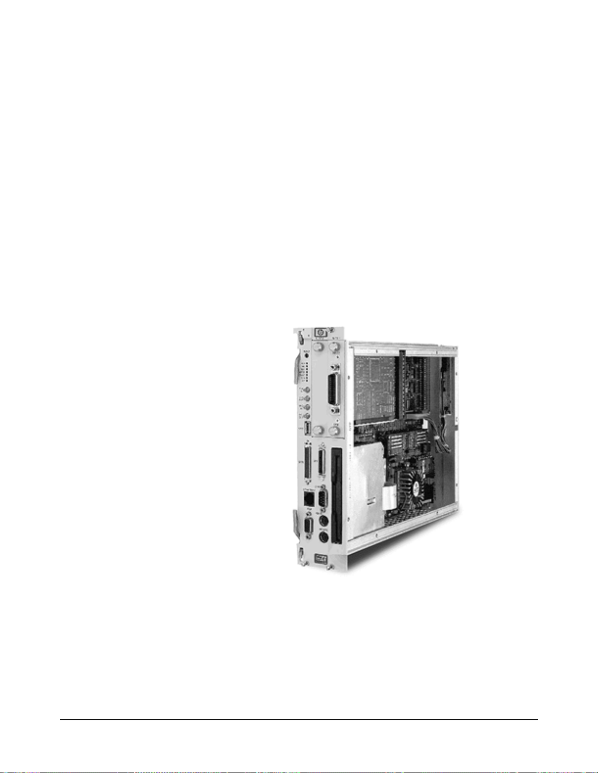
Overview
This guide supports sever al HP p roducts i n the HP VXI Pe ntium Con troller
family. The specific HP product number is marked on the side of the
controller.
The HP VXI Pentium Controller is an Intel Pentium-based, dual-slot, C-size
computer which is PC-compati ble and is designed to interface to the VXIbus
and the EXMbus.
The controller is configured with one of several different speed Intel
Pentium CPUs. Refer to the HP Techn ical Speci fica tions data she et for t he
speed of the CPU in your product.
The controller is configured with varying amounts of DRAM. Refer to the
Main BIOS Setup Menu to verify the amount of memory installed in your
controller.
The controller is shipped pre-loaded with eithe r the Microsoft® Windows
95®, Microsoft Windows NT®, or LynxOS operat ing system as well as the
HP I/O Libraries software for that operating system.
Figure 1-1. The HP VXI Pentium Controller
Introduction 9Chapter 1
Page 12

Major Components The VXI Pentium Controller includes three major components:
•An I/O base board, which contains integrated PCI peripherals for
graphics, SCSI, Enhanced IDE, and Ethernet. The I/O base board also
supports an RS-232 serial port, a parallel port, a keyboard, and a
mouse.
•The CPU submodule which contains the Pentium computer chip and
the SO DIMM sockets. The CPU submodule connects to the I/O base
board.
•An Enhanced IDE disk drive module, which supports 2.5-inch hard
disk drive densities of 1 GB and larger.
In addition to the integrated per ipherals, the VXI Pentium Controller
supports two EXMbus slots and a 3.5-inch floppy disk drive.
10 Introduction Chapter 1
Page 13

Front Panel As shown below, the front panel of the VXI Pentium Controller spans two
VXI slots.
Figure 1-2. The Front Panel of the VXI Pentium Controller
Introduction 11Chapter 1
Page 14

The front panel of the controller contains the following:
•Recessed hardware reset switch (push-button).
•7 LED indicators. (For more information about the meaning of the
LEDs, see Appendix A, “LEDs on the Front Panel.”)
•4 SMB connectors, including: CLK10 IN, CLK10 OUT, TRIGGER
IN, and TRIGGER OUT.
•2 EXMbus slots. (Note that an HP-22 GPIB card is pre-installed in
Slot 1.)
•3.5-inch floppy disk drive.
•9 ports, as listed in the following tabl e.
Table 1-1. Ports on the Front Panel
Label Port Type Connector
COM RS-232 Serial DB9 pin-type
LPT IEEE 1284 Parallel Mini-D36
Where to Go Next
VGA Video VGA 15-pin,
socket-type D-shell
SCSI SCSI Mini-D, 50-pin SCSI II
KBRD Keyboard PS/2-style, 6-pin
circular mini-DIN
MOUSE Mouse PS/2-style, 6-pin
circular mini-DIN
ETHERNET LAN 10-base-T RJ45
a
USB USB Master Host
GPIB HP-22 GPIB GPIB
a.The USB Master Host port is not supported at this time.
Now that you have a better understanding of the VXI Pentium Controller,
you are ready to be gin instal ling the co ntroller har dware. Please go on to the
next chapter, “Installing and Configuring the Hardware,” for instructions on
how to set up the hardware.
USB
12 Introduction Chapter 1
Page 15

Installing and Configuring the Hardware
About this Chapter
Chapter 2
This chapter contains step-by-step instructions to help you set up the HP
VXI Pentium Controller hardware. To install and configure the controller
hardware, you need to complete the following step s.
1. First, before you begin the actual installation:
•Verify the contents of the controller’s product package to ensure you
received all the items for your order.
•Check the location where the controller will be installed to ensure the
environmental conditions meet the controller’s specifications and to
ensure futur e accessibility to the controller.
•Gather the appropriate equipment so it is ready to install.
Before You Begin
2. Install the controller in the VXI card cage.
3. Install an y other interface card(s) in the controller (other than the
HP-22 GPIB card pre-installed in Slot 1.)
4. Connect the peripherals to the controller.
5. Refer to the appropriate HP VXI Pentium Controllers: E623x
Controller User’s Guide for your particular controller for further
instructions on configuring the controller.
The following sections explain how to complete these installation and
configuration steps.
This section explains what st eps you should complete before you be gi n the
actual installation of the VXI Pentium Controller hardware.
Installing and Configuring the Hardware 13Chapter 2
Page 16

Verify the Product
Package
Note The Windows or the LynxOS operating system software, the appropriate
Note If you also ordered a keyboard, mouse, monitor, other interface card(s),
Your VXI Pentium Controller prod uct is shipp ed with the f ollowing i tems.
Once you have unpacked the package, ensure that you received all the
following items with your product order.
•One HP VXI Pentium controller.
•The installation software CD-ROMs and diskettes for the particular
operating system installed on your controller.
HP I/O Libraries software, and the controller drivers and utilities software
are all pre-loaded on the controller’s hard disk. Therefore, the following
software CD-ROMs and floppy diskettes are included in your product
package merely as a contingency, in case you ever need to re-install the
software for any reason.
and/or a CD-ROM drive to use with the VXI Pentium Controller, these
other products (including their documentation and any software, as
appropriate) will be shipped separately to you.
14 Installing and Configuring the Hardware Chapter 2
Page 17

Check the
Installation
Location
Next, ensure that the environmental conditions where you will install the
VXI Pentium Controller will consistently meet the conditions listed in
Appendix C, “Specifications.”
Also, you may want to choose an in stalla tion lo cat ion wher e you can ea sily
access the controller for future updates or changes to the hardware. For
example, upgrading the DRAM memory or setting any jumpers in the
controller will requi re re moving t he cont rolle r fro m the VXI c ard cag e, a nd
then removing the side cover of the controller. (However, setting jumpers
is only required i f reflash ing th e BIOS for a system BI OS upgrad e, which is
rarely, if ever, done.)
Gather the
Equipment Needed
Note Since the V XI Pentium Controller comes pre-loaded with a M icrosoft
Before you begin the installation, you should also have the following
equipment ready to use:
•VXI card cage.
•Optionally, any other interface card(s) you wish to install in the
controller (such as the RADI-EX22/HP-22 GPIB interface,
RADI-EX10 LAN interface, or RADI-EX07 RS-232 interface.)
•PS/2-style or compatible keyboard.
•PS/2-style or compatible mouse, or a serial mouse.
•VGA or better monitor.
•Optionally, a SCSI II CD-ROM drive (such as the HP C2944D
CD-ROM drive .) (See the following Note.)
Windows or the LynxOS operating system, HP I/O Libraries for Windows
or HP SICL for LynxOS, and controller drivers and utilities software, you
do not need to connect a CD-ROM drive to the controller unless you need
to re-install the software for some reason.
Installing and Configuring the Hardware 15Chapter 2
Page 18

Installing the Controller in the VXI Card Cage
Caution You
must
power down the VXI card cage before installing the
VXI Pentium Controller in the card cage. You must also leave
the card cage powered-down until you have finished installing
any other interface card(s) in the controller (if needed) and
connecting the peripherals t o the cont roller, as explained in the
next two sections of this chapter.
To begin the ha rdware installation, you must first install the VXI Pentium
Controller in the VXI card ca ge. To do thi s, first power d own t he VXI car d
cage by turning off the power switch on the card cage. Then insert the
controller into two adjacent, open slots of your VXI card cage (typically,
slots 0 and 1.)
Leave the VX I card cage powered down while you complete the hardware
installation ste ps explained in the next tw o sections of this chapter . You may
power up the VXI card cage (and thereby power up the VXI Pentium
Controller) only after you have completed installing the rest of the hardware
as explained in the following two sections.
Installing Other Interfaces
Note If you have no oth er, separately-purchased interface c ard(s) to install in the
VXI Pentium Controller, simply skip this section and continue with the
next section, “Connecting the Peripherals.”
The VXI Pentium Controller includes one HP-22 GPIB interface card which
is pre-installed in Slot 1 of the controller. If you purchased any other
interface card(s) you wish to use with the controller, then follow the
documentation provide d with each in terface pro duct now to ins tall the ot her
interface card(s) in the contro ller.
Here are some simple remi nders for insta llin g any othe r i nterf ace car d(s) in
the VXI Pentium Controller:
•Note that the existing HP-22 GPIB card was pre-installed in Slot 1
(rather than in Slot 0) to provide better cable clearance for the HP-22
card’s connector on t he front pan el of the contro ller . Theref ore, i f you
wish to install only one more interface c ard, you ma y want to leav e the
existing HP-22 card in Slot 1 and install the new card in Slot 0.
•When removing either the face plate covering Slot 0, or the HP-22
GPIB interface card i n Slot 1, lo osen th e two thumb sc rews on the face
plate or interface’s connector plate. If the screws will not loosen by
hand, use a flat-bladed screw driver to gently turn the screw in the
counter-clockwise direction.
16 Installing and Configuring the Hardware Chapter 2
Page 19

•Be careful when handling an interface card. Hold the interface only by
its exterior connector plate. Never touch any other part of the
interface, particularly the connector itself. Also, protect the interface
from static electricity, since static electricity can damage an interface.
•To insert an interface card into Slot 0 or 1, find the interface card
guides just inside the slot opening, and then slide the interface card
into the controller slot on top of these guides. To seat the card in the
slot, place your thumbs on either side of the exterior connector plate
and press firmly until the card “clicks” into the slot. The connector
plate will be flush with the front panel of the controller when the
interface is completely seated. Then tighten the screws on the
interface’s exter ior con nector plate with your finge rs only. Do not use
a wrench or any other tool to ti ghten thes e screws, as th ey are meant to
be tightened by hand only.
•Because the system BIOS for the controller is pre-configured for an
HP-22 GPIB interface card in Slot 1 onl y, you wi ll need to change the
BIOS configuration if you make any interface card installation
changes. For exampl e, if yo u do any o f the f ollowing, y ou will n eed to
change the BIOS configuration:
-- Add another interface card to Slot 0.
-- Move the existing HP-22 GPIB card from Slot 1 to Slot 0.
-- Remove the existing HP-22 GPIB card from slot 1.
-- Remove the existing HP-22 GPIB card from Slot 1 and replace it
with some other interface card.
You will need to make a ny such BIOS configuration changes aft er you have
completed ins talling the VXI Pentium Controller ha rdware and have
powered up the controller. Therefore, please continue with the next three
sections of this chapter now. You will then be told to reconfigure the BIOS
for any interface card additions or changes at the end of this chapter (in the
“Customizing the Controller” section.)
Installing and Configuring the Hardware 17Chapter 2
Page 20

Connecting the Peripherals
Caution Do NOT power up the VXI card cage and the VXI Pentium
Controller until you make al l connections to the peripheral s, as
explained in this section.
Caution Use extreme caution when connecting peripheral cables to the
controller. The I/O base board of the VXI Pentium Controller
provides power for peripheral devices through different pins.
Making incorrect connections can damage the board and may
damage the peripheral device being connected.
The VXI Pentium Controller suppor ts seve ra l standard, PC-compatible I/O
peripherals, including a keyboard, mouse, and monitor. Before you power
up the controller, you must connect the peripherals as explained in the
following list. Note that you can connect the peripherals in any order.
•Connect a PS/2-style or compatible keyboard (6-pin, mini-DIN
connector) to the KBRD connector.
•Conne ct a PS/2-style or compatible mouse (6-pin, mini-DIN
connector) to the MOUSE connector.
•Optionally, connect a serial mouse to serial port COM1.
•Connect a VGA or better monitor (15-pin, D-shell connector) to the
VGA connector.
•Optionally, connect an HP C2944D CD-ROM drive to the SCSI port.
18 Installing and Configuring the Hardware Chapter 2
Page 21

Powering Up the Controller
Pre-power Checklist Before you power up the VXI Pentium Controller, ensure that you have
completed the following steps.
1. Installed any other EXM interface card(s) in the controller, if needed.
2. Connected all periph erals (includi ng a keyboar d, mouse, and monitor)
to the controller.
3. Turned on the power to the monitor so that it will be warmed up and
ready to display messages before power is applied to the controller.
4. Checked that the power supply to the VXI card cage in which the
controller is installed is connected.
Turning on the
Power
Note Please refer to Chapter 4, “Troubleshooting,” if the RUN LED on the front
Setting the
Controller’s
Internal Clock
Note Setting the internal clock is best done from within your operating system.
When you have completed the previous steps, power up the controller by
simply turnin g on the power switch to the VXI card cage in which the
controller is installed.
panel of the contro ller is not lit or t he TEST LED i s still lit after you power
up the controller.
The controller has an internal clock the value of which is maintained in
battery-backed memory when power is removed from the system. The
setting of this clock as entered by the factory will probably not match your
local time. You are advised to re set the internal clock the first time yo u boot
the controller.
However, it may also be set from the Main BIOS Setup Menu. Skip the
following procedure if you choose to set the time from within your
operating system.
The following line wil l display at the bott om of t h e fi rst page of the system
boot messages:
Press <F2> to enter SETUP
The first time you boot the system, press the F2 function key while this
message is visible in order to set the
your local values.
1. On the Main BIOS Setup Menu, use the up and down cursor keys to
highlight the
System Time field.
Installing and Configuring the Hardware 19Chapter 2
System Time and System Date to
Page 22

2. Use the Tab key to position to the hour, minute, or second fields of
the time.
3. Type in the current local time values in each field.
4. Use the Down cursor key to highlight the
5. Use the
date.
6. Type in th e current local date values in each field.
7. Once the time and date are correct, you may change other BIOS
settings (see the following section, “Customizing the Controller’s
BIOS”) or simply accept the new clock values.
8. To accept the new clock values, use the right and left cursor keys to
change to the Exit Menu, highlight the
and press the
Tab key to position to the month, day, or year fields of the
Enter key. Press the Enter again to continue booting.
Customizing the Controller’s BIOS
Note If you have changed or added to the VXI Pentium Cont ro ller’s hardware in
any way or the default BIOS sett ings f or your co ntrol ler ar e not acc eptable,
you will need to customize your controller’s BIOS.
System Date field.
Save Changes & Exit line,
There may be BIOS customization steps that you still need to complete,
depending on your controller’s particular hardware configuration. If either
of the conditio ns li st ed below apply to your c onf igu ra ti on, you must access
the BIOS Setup Utility during the system boot process.
1. If you installed any other EXMbus interface card(s) in the controller
(other than the HP-22 GPIB card pre-install ed in Slot 1.)
2. If any default configuration value in the system BIOS is not suitable
for your controller’s particular hardware setup.
To access the BI OS Setup Utility, you must press the
the system boot process onc e power has been applied to the co ntroller. Then
go to Chapter 3, “Using th e BIOS Setup Utility,” t o set the appropria te BIOS
configuration values for your system.
F2 function key during
20 Installing and Configuring the Hardware Chapter 2
Page 23

Where to Go Next
Once you have set t he current local t ime and date and complete d configuring
the VXI Pentium Controller’s interfaces, if needed, in BIOS, you are ready
to complete the first boot or your system and to begin configuring the
instrument I/O interfaces (namely, VXI, GPIB, and RS-232C) to the
appropriate VXI Resource Manager and HP SICL library for your
controller. The foll owing subsections list the manual you should use next to
complete the configuration of each controller.
Software
Installation and
Configuration
To continue the insta llat ion of the HP VXI Pentiu m Cont rolle r, ple ase re fer
to the HP VXI Pentium Controllers: E62 3x Contr oller Use r’s Gu ide fo r the
particular controller you are installing.
Installing and Configuring the Hardware 21Chapter 2
Page 24

22 Installing and Configuring the Hardware Chapter 2
Page 25

Using the BIOS Setup Utility
About this Chapter
This chapter explains th e various menus, sub- menus, and fields i n the BIOS
(Basic Input/Output Syst em) Setup uti li ty t hat you can use to configure the
HP VXI Pentium Controller hardware. Since the controller is shipped with
all BIOS Setup values pre-configured, you only need to use this chapter if
you want to make changes to the pre-configured, default BIOS value
settings.
This chapter presents each configuration menu, sub-menu, and field in the
sequence that you would enc ounter it for the first time. Note that on-line hel p
is also available in the
sub-menu.
Accessing BIOS Setup
Item Specific Help
Chapter 3
area of each menu and
Nonvolatile CMOS RAM in t he cont roll er mai ntain s t he BIOS setti ngs t hat
you save. The BIOS uses these settings to initiali ze the har d war e. You c an
access BIOS Setup only during the system reset process. To access BIOS
Setup, press the
F2 function key as the system boots.
Navigating BIOS Setup Menus
Within BIOS Setup, use the cursor (arrow) keys to navigate from menu to
menu and to move between fields in a menu. Use the up and down cursor
keys to move from field to field in a menu. Use the right and le ft cursor keys
to move from menu to menu, as listed in the menu bar at the top of the BIOS
Setup screen. If you le ave a m enu and then r eturn, the acti ve fie ld is alwa ys
at the top of the menu. If you select a s ub- menu and then return t o t he mai n
menu, note that you return to that sub-menu heading.
Using the BIOS Setup Utility 23Chapter 3
Page 26

Main BIOS Setup Menu
The Main BIOS Setup Menu is shown below.
Main Advanced Power EXM Exit
System Time: [16:17:18]
System Date: [03/01/96] <Tab>, <Shift-Tab>, or
Diskette A: [1.44 Mb, 3½”]
Diskette B: [Not Installed]
> IDE Adapter 0 Master (C: 1083 Mb)
> IDE Adapter 0 Slave (None)
Video System: [EGA / VGA]
> Memory Cache:
> Memory Shadow:
> Boot Sequence: [A: then C:]
> Numlock: [Off]
System Memory: 640 Kb
Extended Memory: 31 Mb
F1 Help ↑ ↓ Select Item -/+ Change Values F9 Setup Defaults
ESC Exit ← → Select Menu Enter Select > Sub-Menu F10 Previous Values
The fields in this menu and its various sub-menus are as follows.
PhoenixBIOS Setup - Copyright 1985-95 Phoenix Technologies Ltd.
Item Specific Help
<Enter> selects field.
Figure 3-1. Main BIOS Setup Menu
System Time:
and System Date:
To change the value s for th ese fiel ds, si mply move to eac h fie ld and type i n
the desired entry. Use t he
Tab key to move from hour to minutes to seconds,
or from month to day to year.
Diskette A:
and Diskette B:
IDE Adapter 0 Master: and
IDE Adapter 0 Slave:
Sub-Menus
These fields identify the type of 3.5-inch disk drive installed as the A: and
B: drives. The BIOS defaults to
Installed
1.2 Mb
for drive B:. Other possible values are:
2.88 Mb
, and
.
1.44 Mb, 3 ½”
for drive A:, and
360 Kb, 720 Kb
Not
These fields are headings for sub-menus that allow you to enter complete
disk drive information. Once the information is entered for the drive, the
entry in the Main Menu shows th e drive selec ted. For more i nformati on, see
the “IDE Adap ter 0 Sub-Menus” subsection later in this chapter.
Video System: This field identifies the type of CRT monitor attached to the system. The
possible values are:
EGA / VGA (default)
CGA 80x25
Monochrome
Memory Cache Sub-Menu The term “Memory Cache” ref ers to the technique of cachi ng BIOS images.
For more information, see the “ Memory Cache Sub- Menu” subs ection la ter
in this chapte r.
,
Memory Shadow Sub-Menu The term “Memory Shadow” refers to the tech nique of copyi ng information
from an extension ROM into DRAM and accessing it in this alternate
memory locatio n. The controller restricts what memo ry is available for
shadowing because of the special requir ements for SCSI and the Universe™
24 Using the BIOS Setup Utility Chapter 3
Page 27

PCI/VME bridge. For more information, see the “Me mory Shadow
Sub-Menu” subsection later in this chapter.
Boot Sequence: Sub-Menu The Boot Sequence Sub- Menu allows you to change the boot delay and boot
sequence, and to disable sev eral displays during the boo t process, such as the
SETUP prompt, POST (power-on self-test) errors, floppy drive check, and
summary screen. Once the boot sequence has been set, it is displayed in thi s
field of the Main Menu. For more information, see the “Boot Sequence
Sub-Menu” subsection later in this chapter.
Numlock:
Sub-Menu
(Keyboard Features)
This sub-menu enables or disables various keyboard features, including
enabling the
Num Lock key, enabling the key click, and setting the
keyboard’s auto-repe at rate a nd delay. The Numlock sett ing is dis played in
this field in the Main BIOS Setup Menu. F or more information, s ee the
“Keyboard Features Sub-Menu” subsection later in this chapter.
System Memory: This field is read-only (not editable) and displays the amount of
conventional memory (belo w 1 MB). No user interac tion is re quired. Note
that the amount is actual ly less tha n 640 KB since some memory is used for
the Extended BIOS Data Area, which is required for PS/2 mouse usage.
Extended Memory: This field is also read-only and displays the amount of extended memory
(above 1 MB). No user interaction is required.
IDE Adapter 0
Sub-Menus
There are two IDE Adapte r 0 Sub-Menus for the primar y and secondary hard
disk controllers, each having a master and slave drive screen. The detailed
characteristics of the drive connected to the adapter is available in the IDE
Adapter 0 Sub-Menu, which is shown below.
PhoenixBIOS Setup - Copyright 1985-95 Phoenix Technologies Ltd.
Main
IDE Adapter 0 Master (C: 1038 Mb) Item Specific Help
Autotype Fixed Disk: [Press Enter] <Tab>, <Shift-Tab>, or
Type: [User] 1083 Mb
Cylinders: [ 2100]
Heads: [ 16]
Sectors/Track: [ 63]
Write Precomp: [None]
Multi-Sector Transfers: [16 sectors]
LBA Mode Control: [Enabled]
32 Bit I/O: [Disabled]
Transfer Mode: [Fast PIO 4]
<Enter> selects field.
F1 Help ↑ ↓ Select Item -/+ Change Values F9 Setup Defaults
ESC Exit ← → Select Menu Enter Execute Command F10 Previous Values
Figure 3-2. IDE Adapter 0 Sub-Menus
Autotype Fixed Disk: This is a function which is used when setting up new disks. It allows BIOS
Setup to determine the proper settings of the disk based on information on
the disk. This information is detected by Setup for d rives that comply w ith
ANSI specifications. Press the
Enter key to invoke this function.
Existing (formatted) disks must be set up using the same parameters that
were used originally when t he disk was formatted. If nece ssary, the spec ific
Using the BIOS Setup Utility 25Chapter 3
Page 28

Cylinder, Head, and Sector s/Track information, as listed on the label
attached to the drive at the factory, must be entered manually on this
sub-menu using the User Type, which is described below.
Type: Select
None
if there is no IDE hard disk dr ive for this adapter. In the case
where there is an IDE disk but the
employed, then select the
User
type and enter the correct drive values for
Autotype
function (above) cannot be
Cylinders, Heads, Sectors/ Track, and Write Precomp (pre compensation) for
the drive.
Multi-Sector Transfers: This field allows you to configure the System BIOS to read ahead by the
specified number of sec tors whenever a disk acce ss i s p erf or me d. Thi s ha s
the effect of reading more data at once to reduce the absolute number of
discrete disk reads performed by the ope rat i ng s yst em, whi ch may increase
system performance. The po ssible values are:
sectors
(default). Note that autotyping may change this value if the hard
Disabled
, or 2, 4, 8, or
16
disk reports that it supports block accesses.
LBA Mode Control: When enabled, this fiel d allows the System BIOS to refer ence hard disk data
as logical blocks instead of using the traditional Cylinders/Heads/Sectors
(CHS) method. The
Enabled
value can only be us ed if b oth t he har d disk
being configured and the operating system support Logical Block
Addressing (LBA). If disabled, then CHS mode is used. Note that
autotyping may change this value if the hard disk reports that it supports
LBA. The default is
Enabled
.
32-bit I/O: When enabled, this field allows the System BIOS to access the hard disk
controller with 32-bit I/O accesses, increasing system performance. This
field is not affected by autotyping. The default is
Disabled
.
Transfer Mode: This field sets the mode th at t he System BIOS uses to access the hard disk.
The possible values are:
Standard
Fast PIO 1
Fast PIO 2
Fast PIO 3
Fast PIO 4
(default)
Fast DMA
Older hard disks only support the Standard setting. Newer hard disks
adhering to Fast ATA or Enhanced IDE specifications may support the
Fast PIO (programmed I/O) modes. The Fast DMA mode makes full
use of the onboard bus mastering hard disk controller and should yield the
highest performance when used i n conjuncti on with multi -tasking o perating
systems that support it. Note that autotyping may change this value
depending on the transfer modes that the hard disk reports it supports.
26 Using the BIOS Setup Utility Chapter 3
Page 29

Memory Cache
Sub-Menu
This sub-menu controls the cachability of certain memory regions, as well
as the settings of the Level 2 (L2 ) cache. The Memory Cac he Sub-Me nu is
shown below.
PhoenixBIOS Setup - Copyright 1985-95 Phoenix Technologies Ltd.
Main
Memory Cache Item Specific Help
External Cache: [Enabled] <Tab>, <Shift-Tab>, or
Cache System BIOS Area: [Enabled]
Cache Video BIOS Area: [Enabled]
F1 Help ↑ ↓ Select Item -/+ Change Values F9 Setup Defaults
ESC Exit ← → Select Menu Enter Select > Sub-Menu F10 Previous Values
<Enter> selects field.
Figure 3-3. Memory Cache Sub-Menu
External Cache: This field enables or disables the Level 2 (L2) cache. If this cache is
disabled, system performance will suffer. The default is
Enabled
.
Cache System BIOS Area: This field enables or disables caching of the System BIOS area in the
0E4000H through 0FFFFFH DRAM area. If th is cache is disabled, system
performance will suffer. T he default is
Enabled
.
Cache Video BIOS Area: This field enables or disables caching of the VGA BIOS area in the
0C0000H through 0C7FFFH region. If this cache is disabled, system
performance will suffer. T he default is
Enabled
.
Using the BIOS Setup Utility 27Chapter 3
Page 30

Memory Shadow
Sub-Menu
System Shadow: This field is read-only (not editable) since the System BIOS is always
The term “shadowing” refers to the technique of copying code, such as
BIOS extensions, from ROM i nto DRAM and accessin g them from DRAM.
This allows the CPU to access the BIOS extensions faster and generally
increases system performance if many calls to the BIOS extensions are
made. The Memory Shadow Sub-Menu is shown below.
PhoenixBIOS Setup - Copyright 1985-95 Phoenix Technologies Ltd.
Main
Memory Shadow Item Specific Help
System Shadow: Enabled <Tab>, <Shift-Tab>, or
Video Shadow: [Enabled]
Regions with Legacy Expansion ROMs:
D000-D3FF: [Rom]
D400-D7FF: [Rom]
D800-DBFF: [Rom]
DC00-DFFF: [Rom]
F1 Help ↑ ↓ Select Item -/+ Change Values F9 Setup Defaults
ESC Exit ← → Select Menu Enter Select > Sub-Menu F10 Previous Values
<Enter> selects field.
Figure 3-4. Memory Shadow Sub-Menu
shadowed.
Video Shadow: While it is advisable to leave video shadowing enabled, it is possible to
Regions with Legacy
Expansion ROMs:
disable video shadowing for system performance reasons. The default is
Enabled
.
These fields enable a ROM or disable shadowing for the associated memory
region. There are four 16 KB areas where expansion ROMs can be
shadowed:
D000 - D3FF
D400 - D7FF
D800 - DBFF
DC00 - DFFF
The default for each of these is ROM.
The shadow regions should be used only if an EXMbus card is installed in
the system that contains a BIOS extension (ROM), although there is no
effect on the system if a region is shadowed that does not contain a BIOS
extension. Note that each sha dow region in the Setup menu is 16 KB in size.
Multiple shadow regions may have to be enabled if the BIOS extension to
be shadowed is larger than 16 KB.
28 Using the BIOS Setup Utility Chapter 3
Page 31

Boot Sequence
Sub-Menu
Boot Delay: This field sets the system to del ay booting for a time period in seco nds. This
The Boot Sequence Sub-Menu allows you to change options for the boot
sequence. This sub-menu is shown below.
PhoenixBIOS Setup - Copyright 1985-95 Phoenix Technologies Ltd.
Main
Boot Options Item Specific Help
Boot Delay: [ 0] <Tab>, <Shift-Tab>, or
Floppy Check: [Disabled]
Boot Sequence: [A: then C:]
SETUP Prompt: [Enabled]
POST Errors: [Enabled]
Summary Screen: [Enabled]
F1 Help ↑ ↓ Select Item -/+ Change Values F9 Setup Defaults
ESC Exit ← → Select Menu Enter Select > Sub-Menu F10 Previous Values
Figure 3-5. Boot Sequence Sub-Menu
<Enter> selects field.
allows for long start-up times on boot devices that spin up slowly. The
default is 0 (zero) seconds.
Floppy Check: This field enables or disables the flop py (3.5-i nch dis k) driv e searc h during
the boot. To speed up booting, the floppy check should be disabled. It is
still possible t o boot from th e A: dr ive ev en with the f loppy c hec k disab led.
The default is
Disabled
.
Boot Sequence: This field defines how the system treats the floppy A: drive when booting.
Booting can occur eit her fro m a floppy d isk in t he A: driv e, or dir ectly fr om
the C: fixed disk drive. To reduce the amount of time required to boot, set
the boot sequence to
C: only
. Note that the C: dri ve may be either an IDE
or SCSI drive. The possible values are:
A: then C:
(default) Used to boot from the floppy drive or, if no
floppy disk is present i n the A: drive, to boot f rom the C: drive. This is
useful for troubleshooting the operating system if a boot disk is in
drive A:.
C: then A: Used to boot from the C: drive or, if not present, to boot
from the A: drive.
C: only Used to boot from the C: drive without searching for an A:
drive.
SETUP Prompt: This field enabl es or disables the me ssage Press F2 to enter Setup.
Even if the message is disa bled, you can still pr ess the
F2 function key at the
appropriate time t o enter the Main BIOS Setup Me nu. To speed up booting,
disable the SETUP Prompt. The default is Enabled.
POST Errors: When enabled, this field is used to stop progress during the boot process if
the POST (power-on self-test) encounters errors. Otherwise, the system
Using the BIOS Setup Utility 29Chapter 3
Page 32

continues to attempt to boot despite any start-up error messages that are
displayed. Note that this field only affects those errors that are configured
at build-time to halt the system. The default is
Enabled
.
Summary Screen: This field is used to enable or disable a summary of the system
configuration, which i s displayed before t he operating syst em starts to load.
To speed up booting, disable the Summary Screen. The default is
Enabled
.
Keyboard Features
Sub-Menu
Numlock: This field enables or disables the Numlock feature of the keyboard at boot
This sub-menu, which is accessed from the Numlock: field in the Main
BIOS Setup Menu, enables or disables various keyboard features. The
Keyboard Features Sub-Menu is shown below.
PhoenixBIOS Setup - Copyright 1985-95 Phoenix Technologies Ltd.
Main
Keyboard Features Item Specific Help
Numlock; [Off] <Tab>, <Shift-Tab>, or
Key Click: [Disabled]
Keyboard auto-repeat rate: [30/sec]
Keyboard auto-repeat delay: [1/4 sec]
F1 Help ↑ ↓ Select Item -/+ Change Values F9 Setup Defaults
ESC Exit ← → Select Menu Enter Select > Sub-Menu F10 Previous Values
Figure 3-6. Keyboard Features Sub-Menu
<Enter> selects field.
time. When enabled, Numlock permits the use of the keypad numbers on
the keyboard. The default is
Off
, which disables the Numlock ke y at boo t
time.
Key Click: This field enables or disables the key click feature on the keyboard. When
enabled, the system produces an audible click each time a key is pressed.
The default is
Disabled
.
Keyboard auto-repeat rate: This f ield sets the auto -repeat rate when a ke y is held down on the key board.
The rates range from 2-30 per second. The default rate is 30/sec.
Keyboard auto-repeat
delay:
This field sets the delay between when a key is pressed and when the
auto-repeat feature begins. Options are 1/4, 1/2, 3/4, and 1 (one) second.
The default delay is 1/4 sec.
30 Using the BIOS Setup Utility Chapter 3
Page 33

Advanced Menu
The Advanced Menu contains settings for integrated peripherals, memory
shadow, cache, and la rge di sk acce ss mode. The Ad vanced Men u is sh own
below.
PhoenixBIOS Setup - Copyright 1985-95 Phoenix Technologies Ltd.
Main Advanced Power EXM Exit
Setting items on this menu to incorrect values <Tab>, <Shift-Tab>, or
may cause your system to malfunction.
>Integrated Peripherals:
>Advanced Chipset Control:
Plug & Play O/S: [No]
Reset Configuration Data: [No]
Level 1 Cache: [Enabled]
Large Disk Access Mode: [DOS]
F1 Help ↑ ↓ Select Item -/+ Change Values F9 Setup Defaults
ESC Exit ← → Select Menu Enter Select > Sub-Menu F10 Previous Values
Warning!
Figure 3-7. Advanced Menu
Item Specific Help
<Enter> selects field.
Integrated Peripherals
Sub-Menu
This sub-menu is used to configure the onboard serial (COM) and parallel
(LPT) ports, as well a s the onboard disk c ontrol lers. For more i nformat ion,
see the “Integrated Peripherals Sub-Menu” subsection later in this chapter.
Advanced Chipset Control
Sub-Menu
This sub-menu is used to configure the chipset. For more information, see
the “Advanced Chipset Control Sub-Menu” subsection later in this chapter.
Plug & Play O/S: If enabled, this field informs the System BIOS that the operating system
which is booted supports Plug and Play. This forces the Plug and Play
portion of the System BIOS to only configure motherboard devices and
those peripherals that are necessary for booting (display, hard disk, and so
forth), the rest being left to the operating system to configure. The default
is No (disabled).
Reset Configuration Data: If enabled, this field updates the Extended System Configuration Data
(ESCD) block residing in FBD main block #2. This is necessary the first
time a system is turned on or if the ESCD becomes corrupted. The default
is No (disabled ). This field is automatically reset to No after the ESCD is
updated.
Level 1 Cache: When enabled, this field speeds up the processor by enabling the Level 1
(L1) cache. If the L1 cache is di sabled, system performa nce will suffer. The
default is Enabled.
Large Disk Access Mode: If a hard disk larger th an 528 MB is being used, this field should be set either
to DOS if running MS-DOS, or to Other if using a different operating
system. Setting this field to DOS causes the system BIOS to perform
cylinder/head translation if the drive is configured in BIOS Setup to have
more than 1024 cylinders. This al lo ws MS-DOS syst ems to use har d di sks
up to 8 GB (1024C X 255H X 63S) in size without special drivers or LBA.
Using the BIOS Setup Utility 31Chapter 3
Page 34

Integrated
Peripherals
This sub-menu is used to configure the onboard serial (COM) and parallel
(LPT) ports, as well as the onboard disk controllers. The Integrated
Peripherals Sub-Menu is shown below.
Sub-Menu
PhoenixBIOS Setup - Copyright 1985-95 Phoenix Technologies Ltd.
Advanced
Integrated Peripherals Item Specific Help
COM port: [3F8, IRQ 4] <Tab>, <Shift-Tab>, or
LPT port: [378, IRQ 5]
LPT Mode: [Bi-Directional]
Diskette controller: [Enabled]
Local Bus IDE adapter: [Enabled]
F1 Help ↑ ↓ Select Item -/+ Change Values F9 Setup Defaults
ESC Exit ← → Select Menu Enter Select > Sub-Menu F10 Previous Values
Figure 3-8. Integrated Peripherals Sub-Menu
COM port: This field configures the serial port lab eled “COM1” on the front panel. The
defaults for this COM port are I/O base
3F8H
<Enter> selects field.
IRQ4
and
.
LPT port: This field conf igures t he paral lel port l abeled “ LPT” on the front pa nel. The
defaults for this LPT port are I/O base
378H
and
IRQ5
.
LPT Mode: This field sets the mod e under which t he LPT por t ope rates . The se le ction s
are:
Output only
Bi-Directional
(default)
ECP
Diskette Controller: This field enables or disables the onboard 3.5-inch disk (floppy) drive
controller. The default is
Enabled
.
Local Bus IDE adapter: This field enables or dis ables the onboard PCIb us I DE hard disk control ler.
The default is
Enabled
.
32 Using the BIOS Setup Utility Chapter 3
Page 35

Advanced Chipset
Control Sub-Menu
DRAM Speed: This field sets the sp eed of the insta lled DRAM SODIMMs. Sele cting 70 ns
This sub-menu allows you to control selected settings for the chipset that
affect performance or function. The Advanced Chipset Control Sub-Menu
is shown below.
PhoenixBIOS Setup - Copyright 1985-95 Phoenix Technologies Ltd.
Advanced
Advanced Chipset Control Item Specific Help
DRAM Speed: [60ns] <Tab>, <Shift-Tab>, or
DMA Aliasing: [Enabled]
8-bit I/O Recovery: [4.5]
16 bit I/O Recovery: [4.5]
IRQ12 used by: [PS/2 Mouse]
ECC/Parity Config: [Disabled]
F1 Help ↑ ↓ Select Item -/+ Change Values F9 Setup Defaults
ESC Exit ← → Select Menu Enter Select > Sub-Menu F10 Previous Values
Figure 3-9. Advanced Chipset Control Sub-Menu
<Enter> selects field.
for 60 ns SODIMMs decreases performance. Selecting 60 ns for 70 ns
SODIMMs is invalid. The default is
60ns
.
DMA Aliasing: This field allows I/O accesse s to the range 90-9FH (except 92H) to alias to
80-8FH. If an ISAbu s device uses the addre ss range 90 -9FH, then this fiel d
must be disabled to access the device. The default is
Enabled
.
8-bit I/O Recovery: This field selects the number of ISAbus SYSCLKs to be inserted by the
chipset between 8-bi t ba ck- to -ba ck I / O acc ess es. Increasing the number o f
clocks decreases I/O performance but may allow slow devices to be
accessed properly. Values can range from
1 SYSCLK increments. The default is
4.5
3.5
through
SYSCLKs.
11.5
SYSCLKs, in
16-bit I/O Recovery: This field selects the number of ISAbus SYSCLKs to be inserted by the
chipset between 16 -bit back-to-bac k I/O accesses. Increasing th e number of
clocks decreases I/O performance but may allow slow devices to be
accessed properly. Values can range from
3.5
through
7.5
SYSCLKs, in
1 SYSCLK increments. The default is 4.5 SYSCLKs.
IRQ 12 used by: This field selects the rout ing of IRQ12. For systems withou t a PS/2 mouse,
this field may be set to ISA bus to allow an ISAbus peripheral to use this
interrupt line. Systems us ing a PS/2 mouse must have this field set to PS/2
Mouse (the default) for the mouse to operate correctly.
ECC/Parity Config: This field configures the DRAM controller to use no parity (Disabled),
parity (Parity), or Error Checking and Correction (ECC) when accessing
DRAM. Use of parity or ECC may improve system relia bility since DRAM
errors are likely to be detected by the chipset. Use of ECC allows for the
detection of single and dual bit errors and the cor re ct ion of single bit errors
during DRAM reads. The parity and ECC selections require that all
SODIMMs be x36 instead of x32. The no p arity (disabled) s election can use
Using the BIOS Setup Utility 33Chapter 3
Page 36

either x32 or x36 SODIMMs. The default is
Disabled
. (Note that the VXI
Pentium Controller is shipped with non-parity x32 DRAM.)
34 Using the BIOS Setup Utility Chapter 3
Page 37

Power Management Menu
This menu provides control over the power management facilities. As
shown below, only about one-half of the Power Management Menu fields
are visible at any on e time; however, for compl eteness, all of the menu fields
are listed and explained in this section. Use the
keys to display the other page of fields.
Note that the supported states for system BIOS Power Management are:
Fully On, Standby Mode (partial power reduction), and Suspend Mode
(maximum power reduction). Also note that the Power Management
features are not implemented in the default setups.
PhoenixBIOS Setup - Copyright 1985-95 Phoenix Technologies Ltd.
Main Advanced Power EXM Exit
APM: [Disabled] Item Specific Help
Power Savings: [Disabled]
Standby Timeout: Disabled
Suspend Timeout: DIsabled
Standby CPU Speed: MAX
Fixed DIsk Timeout: Disabled
CRT: ON
Standby Timer Reset Events
Keyboard: [Enabled]
Mouse: [PS/2 (IRQ12)]
Standby Break Events
IRQ0: [Disabled]
IRQ1: [Auto]
IRQ3: [Auto]
F1 Help ↑ ↓ Select Item -/+ Change Values F9 Setup Defaults
ESC Exit ← → Select Menu Enter Select > Sub-Menu F10 Previous Values
Page Up and Page Down
<Tab>, <Shift-Tab>, or
<Enter> selects field.
V
Figure 3-10. Power Management Menu
APM: This field enables or disables Advanced Power Management (APM). The
default is
Disabled
.
Power Savings: This field enable s and selects the kind of powe r mana gemen t, o r i t di sa bles
power management. The possible values are:
Disabled
(default)
Customize
Maximum
Medium
Minimum
Standby Timeout: This field enables and sets the inactivity duration required to elapse before
the system is placed into St andby Mode, or it dis ables the Standby Ti meout.
The possible values are:
Disabled (default)
2 minutes
15 minutes
30 minutes
1 hour
2 hours
Using the BIOS Setup Utility 35Chapter 3
Page 38

3 hours
4 hours
Suspend Timeout: This field enables and sets the inactivity duration required to elapse before
the system is placed into Suspend Mode f rom Sta ndby Mode, or it disables
the Suspend Timeout . The values are the s ame as for t he Standby Timeout ,
listed above. The default is
Disabled
.
Standby CPU Speed: This field enabl es or disables the chan ging of the CPU speed based upon the
current power management state. The possible values are:
Disabled
LOW
MEDIUM
HIGH
MAX
(default)
Fixed Disk Timeout: This field enables and sets the inactivity duration of fixed disk accesses
required to elapse before the system shuts off the disk drive, or it disables
the Fixed Disk Timeout. The possible values are:
1, 2
, 3, 4, 5, 10, or 16 minutes.
Disabled
(default), or
CRT: This field enable s or disables po wer management of the CRT during s ystem
entry or exit into o r from Standby Mode . The possible values are:
Standby
ON in Standby
and
. The default is ON.
OFF in
Standby Timer Reset
Events
This group of fields enables or disables whether or not activity from the
specified device caus es t he Standby Timer to be reset or not. The de fau lt is
Enabled
.
Keyboard: This field enables or disables keyboard activity to reset the Standby
Timer or not. The possible values are:
Disabled
.
Enabled
(default) and
Mouse: This field enables or disables mouse activity to reset the Standby Timer
or not. The possible values are:
Disabled
PS/2 (IRQ12)
(default)
COM1 (IRQ4)
COM2 (IRQ3)
Standby Break Events This group of fields enables or disables a Standby Break Event for the
specified IRQ. A St andby Break Event al lows the system to run at full spee d
for the duration of the specified IRQ. Note that no such event is associated
with IRQ2.
IRQ0-15: Each of these fiel ds enabl es or di sables t he Standb y Break Eve nt for e ach
IRQ. The possible values ar e: Disabled a nd Auto. The default s etting
for IRQ 1, 3, 4, and 12 is Auto. The default setting for all other IRQs is
Disabled.
36 Using the BIOS Setup Utility Chapter 3
Page 39

Standby Wakeup Events This group of fields enables or disables the keyboard or mouse to cause a
Standby Wakeup Event -- that is, these fields allow keyboard or mouse
activity to return the system to full speed.
Keyboard: This field enables or disables the Standby Wakeup Event for the
keyboard. The possible values are:
Enabled
(default) and
Disabled
Mouse: This field enables and selects the IRQ that the mouse is bound to for the
purposes of mouse activity detection for power ma nag ement , or d isa bl es
the Standby Wakeup Event for the mouse. The possible values are:
PS/2 (IRQ12)
(default)
COM1 (IRQ4)
COM2 (IRQ3)
Disabled
.
Using the BIOS Setup Utility 37Chapter 3
Page 40

EXM Menu
The fields in thi s menu allow you t o change the set tings for the EXM m odule
in the system. The HP VXI Pentium Controller comes with an HP-22 GPIB
interface module installed in EXM Slot 1 by default. The EXM Menu is
shown below.
PhoenixBIOS Setup - Copyright 1985-95 Phoenix Technologies Ltd.
Main Advanced Power EXM Exit
EXM Slot 0
ID: [FF] <Tab>, <Shift-Tab>, or
Option Byte 1: [00]
Option Byte 2: [00]
EXM Slot 1
ID: [D9]
Option Byte 1: [FF]
Option Byte 2: [00]
F1 Help ↑ ↓ Select Item -/+ Change Values F9 Setup Defaults
ESC Exit ← → Select Menu Enter Select > Sub-Menu F10 Previous Values
Figure 3-11. EXM Menu
Item Specific Help
<Enter> selects field.
ID: This field selects the EXM-ID for the HP-22 GPIB expansion module. The
default is FF for Slot 0 and D9 for Slot 1.
Option Byte 1: This field selects the I/O addr ess sele ction for the HP-22. The d efault i s FF,
which corresponds to the I/O address 370-377, 770-777, B70-B77, and
F70-F77. Other possible values are:
F9
FB
FD
250-257, 650-657, A50-A57 and E50-E57
270-277, 670-677, A70-A77, and E70-E77
350-357, 750-757, B50-B57, and F50-F57
To disable the HP-22, enter 00.
Option Byte 2: This field is set to 00 (disabled/unused).
Caution To configure a second HP-22 card in EXM Slot 0, make sure that
it is not sharing the same I/O address as the first card
pre-installed in EXM Slot 1. For information on configuring a
second card, see the hardware reference manual shipped with
the card.
38 Using the BIOS Setup Utility Chapter 3
Page 41

Exit Menu
Save Changes & Exit This field is used to save int o CMOS the v alues that have be en entered . The
The fields in this menu allo w you to save value settings and exi t BIOS Setup,
or abandon value changes and exit. The Exit Menu is shown below.
PhoenixBIOS Setup - Copyright 1985-95 Phoenix Technologies Ltd.
Main Advanced Power EXM Exit
Save Changes & Exit
Exit Without Saving Changes <Tab>, <Shift-Tab>, or
Get Default Values
Load Previous Values
Save Changes
F1 Help ↑ ↓ Select Item -/+ Change Values F9 Setup Defaults
ESC Exit ← → Select Menu Enter Execute Command F10 Previous Values
Item Specific Help
<Enter> selects field.
Figure 3-12. Exit Menu
system then immediately reboots with the new values.
Exit Without Saving
Changes
This field is used to discard the changes just made and revert to the state
when BIOS Setup was first entered. The system reboots with the old values.
Get Default Value s This field is used to reset the BIOS Setup values to the original, default
values that were set at the factory, before any suppliers or other end-users
made changes. This is useful if you are having problems wit h the system and
suspect changes made to the BIOS are the cause.
Load Previous Values This field is used to load the system with the previous values before an
editing session started. This is useful if you lose track of edits and want to
revert to the pre vious editing session, but not all the way ba ck to the defau lts.
Save Changes This field is used to save the edits made during a session. You do not exit,
and you can continue to make changes.
Using the BIOS Setup Utility 39Chapter 3
Page 42

40 Using the BIOS Setup Utility Chapter 3
Page 43

About this Chapter
Note For information on:
Chapter 4
Troubleshooting
This chapter helps you resolve error messages or other common problems
you may encounter while installing the VXI Pentium Controller hardware.
This chapter contains the following troubleshooting sections:
•Abnormal LED Indicator States
•BIOS Error Messages
•Problems After Configuring the BIOS
•The meaning of the LED indicators on the front panel of the cont roller,
please see Appendix A.
•Using the BIOS Setup utility, please see Chapter 3.
Abnormal LED Indicator States
The state of the LEDs may indicate the following abnormal conditions.
Table 4-1. Abnormal LED Indicator States
LED Abnormal
State
RUN Not Lit The CPU has halted. Blinking during operation is normal.
TEST Stays Lit The controller did not pass its power-on self-test (POST).
This LED will normally be lit during the POST phase of
the boot. Once POST is complete, it should go out.
SCSI Stays Lit SCSI port operation failed.
IDE Stays Lit IDE disk error.
Cycle the power to the co ntr olle r to s ee if th is pr oblem re ct ifie s its elf. If th e
LED indicators are still in an abnormal sta te, please c ontact your HP Service
and Support Center for assistance. See Appendix F, “POST Beep Codes”,
for additional information that may be useful to service personnel.
Abnormal Condition
Troubleshooting 41Chapter 4
Page 44

BIOS Error Messages
The following table l ists t he BIOS erro r messages you may encoun ter when
powering up and using the VXI Pentium Controller and describes possible
causes and fixes for the errors.
Note If a possible fix that is suggested in the following table requires you to run
BIOS Setup, please see Chapter 3 for more information.
Table 4-2. BIOS Error Messages
BIOS Error Message Description
Diskette drive A error or
Diskette drive B error
EXM Configuration Error
Extended RAM Failed at offset:
Failing Bits:
nnnn
Fixed Disk 0 Failure or
Fixed Disk 1 Failure
or
Fixed Disk Controller Failure
nnnn
Drive A: or B: is present but fails the BIOS
power-on self-test (POST) for the particular
3.5-inch disk drive. Check to see that the drive
is defined with the proper disk type in BIOS
Setup. Also, if the disk drive is an external drive
(rather than the internal drive), ensure that the
disk drive is correctly connected.
The EXM module is not configured properly, or
the BIOS cannot locate the module. Run BIOS
Setup Utility to correct the configuration.
The extended memory is not working or is not
nnnn
configured properly at offset
HP Service and Support Center for assistance.
The hexadecimal number
bits at the RAM address (in System, Extended,
or Shadow memory) which failed the memory
test. Each 1 (one) in the map indicates a failed
bit. Contact your HP Service and Support
Center for assistance.
The fixed disk (internal hard disk drive) is not
working or is not configured properly. Run BIOS
Setup to ensure the disk type is correctly
identified. If this does not fix the problem,
contact your HP Service and Support Center for
assistance.
nnnn
. Contact your
is a map of the
Incorrect Drive A type - run SETUP or
Incorrect Drive B type - run SETUP
Invalid NVRAM media type
42 Troubleshooting Chapter 4
The disk type for drive A: or B: is not correctly
identified in BIOS Setup. Run BIOS Setup to set
the correct disk type.
There is a problem with NVRAM (CMOS)
access. Contact your HP Service and Support
Center for assistance.
Page 45

Table 4-2. BIOS Error Messages (continued)
BIOS Error Message Description
Keyboard controller error
Keyboard error - Keyboard not working
Keyboard error
nn
Keyboard locked - Unlock key switch
Monitor type does not match CMOS -
Run SETUP
Operating system not found
Parity Check 1
The keyboard controller failed a system test.
You may have to replace either the keyboard or
the keyboard controller. Contact your HP
Service and Support Center for assistance.
The system BIOS discovered a stuck key and
nn
displays the scan code
Unlock the system to proceed.
The monitor type is not correctly identified in
BIOS Setup. Run BIOS Setup to set the correct
monitor type.
The Windows operating system cannot be
located on either drive C: or drive A:. Run BIOS
Setup to ensure drive C: (fixed disk/internal
hard disk drive) and/or drive A: (the 3.5-inch
disk drive) are properly identified.
A parity error was found in the system bus. If
the system BIOS located the address where the
parity error occurred, it will also display that
address on the screen. Contact your HP
Service and Support Center for assistance.
for the stuck key.
Parity Check 2
Press <F1> to resume, <F2> to Setup
Press <F2> to enter SETUP
Previous boot incomplete Default configuration used
A parity error was found in the I/O bus. If the
system BIOS located the address where the
parity error occ urre d, it w ill also disp lay it on t he
screen. Contact your HP Service and Support
Center for assistance.
This is displayed after any recoverable error
message. Press the F1 function key to start the
boot process or the F2 function key to enter
BIOS Setup and change any settings.
This is not an error message. Instead, it is an
optional, informational message that is
displayed during the controller’s power-on
self-test (POST). Note that the display of this
message can be turned off in BIOS Setup.
The previous power-on self-test (POST) did not
complete successfully. The POST then loads
the default BIOS configuration values and offers
to run BIOS Setup. If the failure was caused by
incorrect BIOS values that were set and they
are not corrected, the next boot will also likely
fail. Therefore, ensure that all configuration
values are re-set correctl y in BIO S Set up. This
error should then be cleared the next time the
controller is booted.
Troubleshooting 43Chapter 4
Page 46

Table 4-2. BIOS Error Messages (continued)
BIOS Error Message Description
Real time clock error
Shadow Ram Failed at offset:
nnnn
System battery is dead Replace and run SETUP
System cache error - Cache disabled
System CMOS checksum bad - run SETUP
The real-time clock failed the system BIOS test.
This may require repair of the board. Contact
your HP Service and Support Center for
assistance.
The shadow RAM failed at offset
KB block at which the error was detected.
Contact your HP Service and Support Center
for assistance.
The CMOS clock battery indicator shows the
battery is dead. Have the battery replaced
(contact your HP Service and Support Center
for assistance). Then run BIOS Setup to
reconfigur e the controller.
The RAM cache failed the system BIOS test,
and BIOS then disabled the cache. Contact
your HP Service and Support Center for
assistance.
The system CMOS has been corrupted or
modified incorrectly, perhaps by an application
program that changes data stored in CMOS.
Run BIOS Setup and reconfigure the controller
either by restoring the default values or the
previous values and/or making your own
selections.
nnnn
of the 64
System RAM Failed at offset:
System timer error
nnnn
The system RAM failed at offset
KB block at which the error was detected.
Contact your HP Service and Support Center
for assistance.
The timer test failed. This requires repair of the
system board. Contact your HP Service and
Support Center for assistance.
Problems After Configuring the BIOS
If your controller either fails, does not work properly, or displays error
messages after you make configura tion changes in BIOS Set up, you may be
able to correct the problem by entering BIOS Setup again and restoring
either the original, default BIOS configuration values, or the previous
values. This can be done via either the “Get Default Values” or the “Load
Previous Values” selection in the Exit Menu of BIOS Setup.
If after restoring the default or previous BIOS configuration values, your
controller is still not functioning properly, contact your HP Service and
Support Center for assistance.
nnnn
of the 64
44 Troubleshooting Chapter 4
Page 47

Appendix A
LEDs on the Front Panel
There are seven LED indicators on the front panel of the VXI Pentium
Controller which provide information about the state of the controller. The
following table lists the label, color, and meaning o f each LED indicator.
Table A-1. LED Indicators
Label Color Meaning
RUN Green Lit whenever a write access is made to DRAM.
If not lit, either the CPU is executing entirely out
of the on-chip cache, or the CPU is halted.
SYSFAIL Red Lit whenever the VME SYSFAIL line is
asserted.
TEST Yellow Reflects the state of the PASS bit in the VXI
registers. Normally lit during the boot process
until the controller passes all of its self-tests. If it
remains lit, then PASS is 0 (zero), and the
controller has failed its self-test.
MASTER Green Lit when a VME access is made by this device
as a master.
SLAVE Green Lit when another VME device accesses the
memory of this controller.
SCSI Green Lit when the SCSI port is busy.
IDE Green Lit when the IDE disk is busy.
LEDs on the Front Panel 45Appendix A
Page 48

46 LEDs on the Front Panel Appendix A
Page 49

I/O, Memory, and IRQ Details
This appendix provides more detailed technical descriptions of the
following for the VXI Pentium Controller:
•VGA video controller, including its BIOS extension
•SCSI c ontroller, including its BIOS extension
•Ethernet controller
•Memory map
•IRQs (interrupts)
VGA Video Controller
The VXI Pentium Controller c ontains a PCI-bas ed, super -VGA compatibl e
video graphics controller with 2 MB of display memory. The VGA video
controller resides on the PCIbus and is PCI device number 1.
Appendix B
SCSI Controller
The Video BIOS extension is shadowed and write-protected in the region
0x0C0000 to 0x0C7FFF (32 KB) on any system reset or power-up. The
features of the Video BIOS include:
•Standard VGA modes up to 640 X 480 resolution with 16.8 million
colors.
•Super-VGA modes up to 800 X 600 resolution with 16.8 million
colors.
•Extended video modes up to 1280 X 1024 resolution with 256 colors
(non-interlaced).
The SCSI BIOS extension is automatically shadowed in system DRAM at
memory location 0x0C8000 to 0x0CFFFF.
The SCSI device resides o n the PCIbus and is mapped a s PCI device number
3. The SCSI controller uses PCIbus interrupt INTC. The default I/O base
address and interrupt is 0xC180 and IRQ11, respectively.
I/O, Memory, and IRQ Details 47Appendix B
Page 50

Ethernet Controller
Memory Map
The Ethernet control le r r es ide s on the PCIbus and is mappe d a s PCI device
number 2. It uses PCIbus interrupt INTB.
Network booting is not supported.
The Ethernet port supports only a 10-base-T interface.
Table B-1. Memory Map
Pentium Address Range
00000000-0009FFFF DRAM Yes
000A0000-000BFFFF VGA Memory No
000C0000-000C7FFF Shadowed VGA BIOS Yes
000C8000-000CFFFF Shadowed SCSI BIOS Yes
000D0000-000DFFFF On-board EXMbus No
000E0000-000E3FFF VXI Interface Chip No
00100000-07FFFFFF DRAM
08000000-0FFFFFFF EXMbus No
10000000-1FFFFFFF Reserved No
20000000-3FFFFFFF Reserved No
40000000-7FFFFFFF Reserved No
80000000-83FFFFFF VXI Interface Chip Image 0 No
84000000-87FFFFFF VXI Interface Chip Image 1 No
a
If no DRAM, ISA memory
Region Cached
Yes
No
88000000-8BFFFFFF VXI Interface Chip Image 2 No
8C000000-8FFFFFFF VXI Interface Chip Image 3 No
90000000-93FFFFFF VXI Interface Chip Image 4 No
94000000-EFFFFFFF Reserved No
F0000000-FFF7FFFF EXMbus No
FFF80000-FFFFFFFF Flash Boot Device No
a.All addresses are hexadecimal.
48 I/O, Memory, and IRQ Details Appendix B
Page 51

IRQs (Interrupt Request Lines)
Interrupt Source
Table B-2. IRQs (Interrupt Request Lines)
IRQ0 Timer
IRQ1 Keyboard Controller
IRQ2 Cascade Interrupt Input
IRQ3 COM2 (Not externally available)
Use for second HP-22 on Windows 95
IRQ4 COM1
IRQ5 ECP Printer Port (LPT1)
Use for second HP-22 on Windows NT
IRQ6 3.5-inch Disk Drive
IRQ7 Reserved for HP-22
IRQ8 Real-time Clock
IRQ9 VXI Interface Chip
IRQ10 VXI Interface Chip
IRQ11 SCSI
IRQ12 Mouse
IRQ13 Numeric Co-processor
IRQ14 IDE
IRQ15 Ethernet
NMI EXMbus I/O Channel Check Asserted
SMI Power Management
INTA VGA (not mapped)
INTB Ethernet (mapped to IRQ15)
INTC SCSI (mapped to IRQ11)
INTD VXI Interface Chip (mapped to IRQ9)
I/O, Memory, and IRQ Details 49Appendix B
Page 52

50 I/O, Memory, and IRQ Details Appendix B
Page 53

Environmental
Appendix C
Specifications
This appendix lists the environmental and electrical specifications for the
VXI Pentium Controller. See the Declaration of Conformity at the front of
this manual fo r information on EM C and Safety standards compliance.
The following table defines the environmental specifications for the I/O
base board in the VXI Pentium Con troller.
Table C-1. Environmental Specifications
Characteristic Operating Value Non-Operating
(Storage) Value
Temperature 5°C to 45°C, derated 2°C
per 1,000 feet (300
meters) over 10,000 feet
(3,000 meters); 2°C per
minute maximum
excursion gradient
Humidity 8% to 90%
non-condensing
Altitude 0 to 10,000 feet (3,000
meters)
Vibration 0.015 inch (0.38 mm) P-P
displacement with 2.5 g
peak (maximum)
acceleration over 5 to 300
Hz
Shock 30 g, 11 ms duration,
half-sine shock pulse
-40°C to +65°C, 5°C per
minute maximum
excursion gradient
5% to 95%
non-condensing
0 to 40,000 feet (12,000
meters)
0.030 inch (0.76 mm) P-P
displacement with 5.0 g
peak (max imum)
acceleration over 5 to 300
Hz
50 g, 11 ms duration,
half-sine shock pulse
Specifications 51Appendix C
Page 54

Electrical
The following table defines the electrical specifications for the controller’s
I/O base board.
Table C-2. VXI Pentium Controller Power Requirements
Voltage DC Current Dynamic Current
+5 V dc 11 A 0.31 A
+12 V dc 40.2 mA 0.08 A
-12 V dc 2.4 mA 0.03 A
-2 V dc 120 mA 0.08 A
-5.2 V dc 335 mA 0.192 mA
a.These specificat ions ar e for an HP VX I Cont roller
with a 166 MHz processor. The power
requirements for a controller with a slower
processor will be lower. The po wer requirements
for a controller with a faster processor will be
somewhat higher. Refer to your HP product’s
Technical S pecification s data sheet for exact
information.
a
52 Specifications Appendix C
Page 55

Appendix D
Installing BIOS Software
This appendix explains how to reflash the system BIOS in the HP VXI
Pentium Controller from the controller’s floppy disk drive. This process is
rarely done only when the BIOS stored in the contr oller’s flash memor y has
been damaged or when HP releases a new version of the BIOS to correct a
specific problem or to add support for new system features.
Note The special BIOS boot diskette referred to in the instructions below is not
shipped with your HP VXI Pentium Controller. If required, it must be
obtained from an HP Support Representative.
Caution It is strongly recommended that a trained computer service
technician performs the installat ion and removal of the jumpers
referred to in the instructions below. An HP Service Technician
can perform this task for you. Contact your HP Service and
Support Center for assistance.
Overview
The HP VXI Pentium Controller’s System BIOS is updated by using a
special boot diskette that contains the System BIOS image as well as the
code to perform the update.
To enable the recovery process and to allow writing to the flash memory
which contains the BIOS, two jumpers must be installed on jumper-pin
connector blocks located inside the controller. To access the jumper-pin
connector blocks, the controller must be powered down and removed from
the VXI mainframe in order to remove the side cover panel.
Once the jumpers have been instal led and the control ler re turned t o the VXI
mainframe, the system must be booted with the special BIOS boot diskette
loaded in the floppy disk drive. The recovery process will then automatically
update the BIOS.
Once the recovery pro cess is complete, the c ontroller must be power ed down
and the jumpers removed before you can return to normal operation.
Installing BIOS Software 53Appendix D
Page 56

Record
CMOS/BIOS
Prior to reflashin g the sys tem BIOS in the HP VXI Pentium Cont roller, you
should record all CMOS/BIOS system settings.
Settings
1. Apply power to the VXI mainframe. During system boot-up, press F2.
2. Record all settings.
3. Power-down the VXI mainframe.
Jumper Installation Procedure
Caution The circuitry in the HP VXI Pentium Controller can be damaged
by electrostatic discharge. All work must be done by a trained
technician at a static-free workstation.
Tools Required You will need the following tools to access the controller’s main circuit
board and install the pin jumpers:
•two, 2-position, 2.5 mm, removable jumpers; Optionally, you may
need a third, jumper.
•a grounding wrist strap and static-free workstation; and
•a #0 (small) Phillips screw driver.
Disassembly Steps 1. At a static-free wor kst at ion, place the HP VXI P ent ium Co ntr ol le r o n
its left side s uch that the front panel i s facing you and the sheet-metal
cover with its bar-coded serial number is on the far edge away from
you.
2. Attach the grounding strap to your wrist and take appropriate
anti-static precautions during the rest of this procedure.
3. With the #0 Phillips screwdr iver, remove the eight Phillips-head
screws holding the sheet -metal cover t o the cha ssis. Do not l ose the se
very small screws. They will be needed to re-attach the cover.
4. Remove the sheet-metal cover and set it aside.
The two jumperconnector blocks, labelled P7 and P8, are located just
to the left of the power cable connector (see the multi-colored wire
harness) on the main I/O base board near the rear-center of the unit.
54 Installing BIOS Software Appendix D
Page 57

5. Place a jumper to connect pin 7 to pin 8 on jumper block P7 and a
jumper to connect pin 1 to pin 3 on jumper block P8 as shown below:
Install these jumpers
2
P7
1
2
P8
1
Figure D-1. Jumper-Pin Connector Blocks
6. Replace the sheet-metal cover such that the bent edges on the sides
are down and the bar-cod ed ser ial numbe r lab el is o n the e dge near est
the VXI connector blocks on the rear of the unit.
7. Using the #0 Phillips screwdriver, replace the eight Phillips-head
screws holding the sheet-metal cover to the chassis. Gently tighten
the screws be ing careful not to strip the threads.
8. Return the controller to its slot in the VXI mainframe.
Booting the Special BIOS Boot Diskette
Perform the following procedur e to boot t he speci al BIOS boot diskette a nd
write the system BIOS into the controller’s flash memory:
10
9
6
5
Note The video monitor is not operative during the recovery process. The
progress of the reco ver y is communi ca te d to the operator via au dib le bee ps
from the controller’s internal speaker.
1. With the VXI mainframe p owered down, insert the sp ecial BIOS b oot
diskette into the controller’s floppy disk drive.
2. Power on the VXI mainframe. The controller will start booting from
its floppy disk drive.
The boot program will issue three beeps when the actual recovery
process begins. The first series of beeps from the recovery program
denotes the reading of the System BIOS file. The last series of beeps
denotes the erasing of the flash memory and reloading of the BIOS
code. A single long beep denotes the successful recovery of the
System BIOS and that the system is about to reset itself.
Installing BIOS Software 55Appendix D
Page 58

Note If the system will not boot from the floppy diskette and the system has SO
DIMM installed in only the right memory bank (b ank 1), move t he memory
from bank 1 to bank 0 (left bank) and retry th is procedur e. See Appendix E,
“Installing Additional DRAM Memory”, for instructions on how to move
the memory.
Alternate Installation Note If after 45 to 50 seconds, th e singl e long beep has not oc curred ; but i nstea d,
you repeatedly hear a short beep followed by the muted chatter of the disk
drive (it may sound like a muffled buzz), turn off the VXI mainframe.
Refer to “Alternate Installation,” later in this section.
3. When the single long beep has been issued and the system reset
begins, you must immediately power down the VXI mainframe.
Otherwise, the boot from the special BIOS boot diskette will start
again and the recovery process will repeat.
4. Remove the BIOS boot diskette from teh controller’s disk drive.
5. Remove th e HP VXI Pentium Controller from the VX I mainframe
and take it to a static-free workstation in order to remove the jumpers
you installed earlier.
Note All jumpers installed on P7 and P8 must be removed to prevent later
accidental writing of the System BIOS.
6. Return to the section a bove titled Disassembly Procedure and fol low
the instructio ns to remove the cover panel. But, this time, remo ve the
jumpers from jumper blocks P7 and P8.
7. Connect the video monitor, keyboard, and mouse to the HP Pentium
Controller.
8. Apply power to the VXI mainframe.
9. Press
10.Select the
11.Reset all the CMOS/BIOS system settings to those recorded earlier.
12.Select the
F2 during the normal boot of the VXI system.
EXIT menu, then select Get Def a ult Values. Press the
ENTER key. This resets everything in the BIOS.
See Record CMOS /BIOS Settings.
MAIN menu., then select IDE Adapter 0 Master. Select
Autotype Fixed Disk. Press the ENTER key to auto-detect the fixed
disk on the controller.
56 Installing BIOS Software Appendix D
Page 59

13.Select the EXIT menu. Save the changes then select the EXIT button.
14.Cycle power on the VXI mainframe and allow the system to
power-up normally. The system is now ready for use.
This completes the reflashing of the HP VXI Pentium Controller BIOS. The
system is now ready for normal operation.
Alternate
Installation
Follow this installation procedure only if the normal BIOS boot procedure
resulted in an alternating beep and the muted chatter of the disk drive.
1. Remove th e HP VXI Pentium Controller module from the VXI
mainframe.
2. Following the Disassembly Steps earlier in this section, remove the
sheet metal cover.
3. Install a third jumper between pins 2 and 6 on jumper block P8. Refer
to Figure D-2.
2
P7
1
2
P8
1
Figure D- 2. Jumper-Pin Connector Blocks for Alt ernate Installati on
10
9
6
5
Install jumper with wire
4. Reassemble the sheet metal cover.
5. Return the controller to its slot in the VXI mainframe.
6. Follow the procedures in Booting the Special BIOS Boot Diskette.
Installing BIOS Software 57Appendix D
Page 60

58 Installing BIOS Software Appendix D
Page 61

Appendix E
Installing Additional DRAM Memory
This appendix explains how to install additional DRAM memory into the
HP VXI Pentium Controller.
Caution It is strongly recommended that a trained computer service
technician installs any memory upgrade, as SO DIMMs are
more flexible than common SIMMs and are also more costly if
damaged. There is also potential for damage to the controller
itself. An HP Service Technician can perform this task for you.
Contact your HP Service and Support Center for assistance.
The HP VXI Pentium Controller has four SO DIMM sockets supporting
from 16 MB to 256 MB of dual-ported, DRAM memory. The standard
controller comes with two SO DIMM modules installed in two sockets. This
leaves two open sockets available for additional memory.
Please note that because the memory is interleaved, the sockets must be
populated in pairs of identical SO DIMM modules. However, memory
module densities of upgra des may be mixed. For e xample, if two 8 MB SO
DIMM modules occupy th e first two sockets, the remaining two sockets may
be occupied by two SO DIMM modules of any other supported density. If
mixed memory module densities are used, there is no dependency on the
order in which the module pairs are loaded into the sockets pairs.
While the HP VXI Pentium Controller can support both 60ns and 70ns
memory speeds, it is not recommend to mix memory of different speeds in
the same unit. If you chose to ignore this re commendation and inst all slower
speed 70ns memory in a unit which alrea dy has 60ns memory pre- install ed,
you must set the
Sub-Menu to
will cause all the memory in the unit to operate at the same, slower 70ns
speed.
DRAM Speed setting in the BIOS Advanced Chipset Control
70ns (See Chapter 3, “Using the BIOS Setup Utility”). This
Installing Additional DRAM Memory 59Appendix E
Page 62

Memory Specifications
The following table lists the memory specifications for the HP VXI
Pentium Controller.
Type EDO DRAM (Standard),
Form SO (Small Outline) DIMM
Number of Pins 72
Voltage 3.3 V
Speed 60ns (Standard),
Bit Width x32
Parity No
Refresh Rate 1 K/sec, 2 K/sec, or 4K/sec
Density/SO DIMM 8 MB, 16 MB, 32 MB, or 64 MB
Number of Sockets 4, interleaved
Table E-1. Memory Specifications
Fast Page Mode DRAM (Not Recommended)
70ns (Not Recommended)
a
Minimum Size 16 MB (2x8 MB)
Maximum Size 256 MB (4x64 MB)
Ordering HP Memory
Two additional memory kit products are available from Hewlett-Packard.
Note that each ki t includes two SO DIMMs o f the appropriate siz e to result
in the total memory upgrade size.
a.64 MB SO DIMMs require BIOS revision 1.01.04 or above.
Table E-2. HP Memory Upgrade Kits
HP Product No. Upgrade Size SO DIMM Density
E6245A 16 MB 2x8MB
E6246A 32 MB 2x16MB
60 Installing Additional DRAM Memory Appendix E
Page 63

Referenced Memory Parts
The following table lists the vendor and part number of other qualified
memory parts. Please note that these memory modules must be ordered and
installed in pairs.
Table E-3. DRAM Memory Parts List
SO DIMM Density Manufacturer Name Mfg. Part Number
1x32 MB Simple Technology, Inc. STI328014D1-60VG
1x64 MB
a.These products are referenced by Hewlett-Packard. They are manufactured and
sold by the respective manufacturer listed in this table. HP does not sell,
distribute, warrant, or support these products.
b.64 MB SO DIMMs require BIOS Revision 1.01.04 or above.
b
Ordering Referenced Memory
Additional DRAM memory mu st be pur chased di rectly fro m the r eferenced
product manufacturer or its distributors. The contact information for each
manufacturer listed bel ow is supplied only for the conv enience of the reader
and is not guaranteed by HP to be correct or current.
Simple Technology, Incorporated
3001 Daimler Street
Santa Ana, California 92705
Sales & Technical Support: 1-800-367-7330
International Sales: (714) 476-1180
General Assistance: (714) 476-1180
Fax: (714) 476-1209
BBS: (714) 476-9034
Toll-Free fax-back service (international): 1-800-429-5626, ext. 500
E-Mail: info@simpletech.com
WWW: http://www.simpletech.com/
a
Unigen Corporation UG316W3248HSG-6
Unigen Corporation
45388 Warm Springs Boulevard
Fremont, California 94539
International Sales: (510) 668-2088
General Assistance: (510) 668-2088
Fax: (510) 661-2788
U.S. East Coast: 1-800-711-7140
U.S. West Coast: 1-800-826-0808
Other Offices: New York, Hong Kong, and Tokyo
E-Mail: unigen@ix.netcom.com
WWW: http://www.unigen.com/
Installing Additional DRAM Memory 61Appendix E
Page 64

Installation Procedure
Caution The integrated circuit components in these products can be
damaged by electrostatic discharge. All work must be done by
a trained technician at a static-free workst ation.
The SO DIMM modules are fragile. Care must be taken to not
bend or twist them during installation.
Tools Required You will need the following tools to access the controller and install the SO
DIMM modules:
•a grounding wrist strap and static-free workstation; and
•a #0 (small) Phillips screw driver.
SO DIMM
Installation
Requirements
Ensure that t he following requirements are met.
•SO DIMM modules must be installed in pairs with each module in a
pair being identical.
•The SO DIMM modules being installed must be of the same type and
speed, but not necessarily size, as the pre-installed modules.
Installation Steps 1. At a static-free workstation, pl ace t he HP VXI Pentium Control le r o n
its left side s uch that the front panel i s facing you and the sheet-metal
cover with its bar-coded serial number is on the far edge away from
you.
2. Attach the grounding strap to your wrist and take appropriate
anti-static precautions during the rest of this procedure.
3. With the #0 Phillips screwdr iver, remove the eight (8) Phillips-head
screws holding the sheet -metal cover t o the cha ssis. Do not l ose the se
very small screws. They will be needed to re-attach the cover.
4. Remove the sheet-metal cover and set it aside.
The CPU sub-module printed-c ircuit board is attached to the main I/O
base board in the upper-right corner of the unit. Two memory banks,
each with two SO DIMM sockets, ar e located o n the CPU sub-mod ule
just above the CPU cooling fan. The right memory bank will already
be occupied by the pre-installed SO DIMM modules. The new SO
DIMM modules are to be inserted into the left memory bank.
5. Carefully remove the first SO DIMM module from its packaging.
Take care to handle it only by its non-conductive edges and to not
touch the pin-connectors.
62 Installing Additional DRAM Memory Appendix E
Page 65

6. Orient the SO DIMM module such that the corner cutout on its
pin-connector edge aligns with the matching corner bulge of the
socket receptacle. This may result in the DRAM chips being on the
top or bottom surface depending on the orientation of the memory
bank sockets and the placement of the chips on the module.
The SO DIMM modules and sockets are physically keyed to each
other such that a module wi ll f it i nto a socke t only one way . E ach SO
DIMM module has a small, rounded cutout on one corner of its
pin-connector edge. Each SO DIMM socket has a small, rounded
bulge on one of its recept acle corners . The two p arts fit i nto each ot her
like a key. If the parts are not properly oriented in relationship to each
other, you cannot insert the module into the socket.
7. The first SO DIMM module must be inserted into the lower socket of
the memory bank. Slide the SO DIMM module at a slightly
downward angle between the upper and lower retaining clips
directing its pin-connectors into the lower socket.
8. Once the pin-connectors have made contact with the socket, gently
press along the entire edge of the SO DIMM module to firmly seat the
module into the socket. At the same time, the outside edge of the SO
DIMM module should be tilted slightly downward such that the
retainer clips of the socket engage the matching retainer cutout slots
on the module’s top and bottom edges.
9. Repeat steps 5 and 6 for the second SO DIMM module.
10.The second SO DIMM module must be inserted into t he upper socke t
of the memory bank. Slide the SO DIMM mo dule at a slightly
downward a ngle above the up per retaining clips directing its
pin-connectors into the upper socket.
11.Repeat step 8 for the second SO DIMM module.
12.Replace the sheet-metal cover such that the bent edges on the sides
are down and the bar-coded serial number label is on the edge away
from you.
13.With the #0 Phillips screwdriver , replace the eight (8) Phillips-head
screws holding the sheet-metal cover to the chassis. Tighten the
screws gentl y being careful not to strip the threads.
The installation of the memory upgrade is now complete. When power is
next applie d to the HP VXI Pentium controller , the system BIO S will
automatically detect and configure the new memory.
Installing Additional DRAM Memory 63Appendix E
Page 66

64 Installing Additional DRAM Memory Appendix E
Page 67

Appendix F
POST Beep Codes
If valid BIOS code cannot be loaded from the BIOS memory, the cont roller
will issue two beeps and halt the CPU.
The rest of this appendix lists the codes which are written to the diagnostic
port of the HP VXI Pentium Controller during the power-on self-test
(POST) phase of the system boot. The POST Codes listed in the tables below
are viewable only by HP service personnel with the proper diagnostic
equipment.
The audible Beep Codes li sted i n the t ables below wil l be i ssued on ly when
the associate d self-test detec ts a failure. This in formation, if available, is
useful to the HP Service and Support Center when you report a problem.
Phoenix NuBI O S
Checkpoint s
The Phoenix NuBIOS writes a number of checkpoints to I/O port 80h just
before each self-tes t is executed. Note t hat the executi on order of the POST
tests generally follows the order listed in the tables below, but not exactly.
Table F-1. Phoenix NuBIOS Checkpoint Codes
Beep
Code
02h Verify Real Mode
04h Get CPU type
06h Initialize system hardware
08h Initialize chipset registers with initial POST values
09h Set in POST flag
0Ah Initialize CPU registers
0Ch Initialize cache to initial POST values
0Eh Initialize I/O
10h Initialize Power Management
11h Load alternate registers with initial POST values
POST
Code Checkpoint Description
12h Jump to UserPatch0
14h Initialize keyboard controller
1-2-2-3 16h BIOS ROM checksum
18h 8254 timer initialization
1Ah 8237 DMA controller initialization
POST Beep Codes 65Appendix F
Page 68

Table F-1. Phoenix NuBIOS Checkpoint Codes (continued)
Beep
Code
1Ch Reset Programmable Interrupt Controller
1-3-1-1 20h Test DRAM refresh
1-3-1-3 22h Test 8742 Keyboard Controller
24h Set ES segment to register to 4GB
28h Autosize DRAM
2Ah Clear 512KB base RAM
1-3-4-1 2Ch Test 512KB base address lines
1-3-4-3 2Eh Test 512KB base memory
32h Test CPU bus-clock frequency
37h Reinitialize the chipset
38h Shadow system BIOS ROM
39h Reinitialize the cache
3Ah Autosize cache
POST
Code Checkpoint Description
3Ch Configure advanced chipset registers
3Dh Load alternate registers with CMOS values
40h Set Initial CPU speed
42h Initialize interrupt vectors
44h Initialize BIOS interrupts
2-1-2-3 46h Check ROM copyright notice
47h Initialize manager for PCI Option ROMs
48h Check video configuration against CMOS
49h Initialize PCI bus and devices
4Ah Initialize all video adapters in system
4Ch Shadow video BIOS ROM
4Eh Display copyright notice
50h Display CPU type and speed
52h Test keyboard
54h Set key click if enabled
56h Enable keyboard
2-2-3-1 58h Test for unexpected interrupts
66 POST Beep Codes Appendix F
Page 69

Table F-1. Phoenix NuBIOS Checkpoint Codes (continued)
Beep
Code
5Ah Display prompt “Press F2 to enter SETUP”
5Ch Test RAM between 512KB and 640KB
60h Test extended memory
62h Test extended memory addre ss line s
64h Jump to UserPatch1
66h Configure advanced cache registers
68h Enable external and CPU ca che s
6Ah Display external cache size
6Ch Display shadow message
6Eh Display non-disposable segments
70h Display error messages
72h Check for configuration errors
74h Test real-time clock
POST
Code Checkpoint Description
76h Check for keyboard errors
7Ch Set up hardware interrupts vectors
7Eh Test coprocessor if present
80h Disable onboard I/O ports
82h Detect and install external RS232 ports
84h Detect and install external parallel ports
86h Re-initialize onboard I/O ports
88h Initialize BIOS Data Area
8Ah Initialize Extended BIOS Data Area
8Ch Initialize floppy controller
90h Initialize hard disk controller
91h Initialize localbus hard disk controller
92h Jump to UserPatch2
94h Disable A20 address line
96h Clear huge ES segment register
98h Search for option ROMs
9Ah Shadow option ROMs
POST Beep Codes 67Appendix F
Page 70

Table F-1. Phoenix NuBIOS Checkpoint Codes (continued)
Beep
Code
9Ch Set up Power Management
9Eh Enable hardware interrupts
A0h Set time of day
A2h Check keylock
A8h Erase F2 prompt
AAh Scan for F2 keystroke
ACh Enter SETUP
AEh Clear in-POST flag
B0h Check for errors
B2h POST done--prepare to boot operating system
B4h One beep
B6h Check password (optional)
B8h Clear global descriptor table
POST
Code Checkpoint Description
BCh Clear parity checkers
BEh Clear screen (optional)
BFh Check virus and backup reminders
C0h Try to boot with INT19
Table F-2. Phoenix NuBIOS Auxiliary Checkpoint Codes
Beep
Code
D0h Interrupt handler error
D2h Unknown interrupt error
D4h Pending interrupt error
D6h Initialize option ROM error
D8h Shutdown error
DAh Extended Block Move
DCh Shutdown 10 error
POST
Code Checkpoint Description
68 POST Beep Codes Appendix F
Page 71

Table F-3. Phoenix NuBIOS Boot Block Checkpoint Codes
Beep
Code
E2h Initialize the chipset
E3h Initialize refresh counter
E4h Check for Forced Flash
E5h Check HW status of ROM
E6h BIOS ROM is OK
E7h Do a complete RAM test
E8h Do OEM initialization
E9h Initialize interrupt controller
EAh Read in bootstrap code
EBh Initialize all vectors
ECh Boot the Flash program
EDh Initialize the boot device
EEh Boot code was read OK
POST
Code Checkpoint Description
POST Beep Codes 69Appendix F
Page 72

70 POST Beep Codes Appendix F
Page 73

Index
B
Beep Codes, 65
BIOS extension
, 47
SCSI
VGA video, 47
BIOS Setup utility
Advanced Menu
Advanced Chipset Control Su b-Menu, 33, 59
Integrated Peripherals Sub-Menu, 32
configuration procedures, 23
error messages, 42
Exit Menu, 39
exiting without saving changes, 39
EXM Menu, 38
Main BIOS Setup Panel, 24
Boot Sequence Sub-Menu, 29
IDE Adapter 0 Sub-Menus, 25
Keyboard Features Sub-Menu, 30
Memory Cache Sub-Menu, 27
Memory Shadow Sub-Menu, 28
Numlock (Keyboard Features) Sub-Menu, 30
Power Management Menu, 35
problems after configuring, 44
restoring default values, 39
restoring previous values, 39
saving changes and exiting, 39
saving changes without exiting, 39
setting internal clock, 19
BIOS, recovery from diskette, 53
, 31
C
Card cage, installing controller in, 16
Checklist, before power-up, 19
Clock, setting, 19
Configuring
BIOS Setup utility
controller hardware, 13
list of possible steps, 20
Conformity, Declaration of, 5
EMC, 5
safety, 5
Connecting peripherals to the controller, 18
Connectors on front panel, 12
, 23
Controller
BIOS error messages
BIOS Setup utility, 23
connecting peripherals , 18
connectors on front panel, 12
customizing, 20
diagnostic beep codes, 65
electronic components, 10
Ethernet controller, 48
front panel, 11
hardware installation and configuration, 13
installing in VXI card cage, 16
installing memory, 59
installing other interfaces, 16
IRQs, 49
LED abnormal states, 41
LEDs on front panel, 45
memory map, 48
memory specifications, 60
overview, 9
ports on front panel, 12
powering up, 19
problems after configuring the BIOS, 44
SCSI Controller and BIOS extension, 47
setting internal clock, 19
specifications, 51, 65
troubleshooting, 41
verifying the product package, 14
VGA video controller and BIOS extension, 47
Customizing
BIOS Setup utility
list of possible steps, 20
, 42
, 23
D
Date/time, se tting, 19
Declaration of Conformity, 5
Diagnostic beep codes, 65
E
Electrical specif ic at ions, 52
EMC conformation, 5
Environmental specifications, 51
Error codes, self-test, 65
Error messages, BIOS, 42
Index 71
Page 74

F
Flashing, BIOS software, 53
Front panel, 11
H
Hardware
BIOS error messages
BIOS Setup utility, 23
connectiong peripherals, 18
connectors on front panel, 12
customizing, 20
diagnostic beep codes, 65
electronic components, 10
Ethernet controller, 48
front panel , 11
installation and configuration, 13
installing contro ll er in VXI card cage, 16
installing memory, 59
installing other int er fa ces, 16
IRQs, 49
LED abnornal states, 41
LEDs on front panel, 45
memory specifications, 60
ports on front panel, 12
powering up, 19
problems after configuring the BIOS, 44
SCSI Controller and BIOS extension, 47
troubleshooting, 41
VGA video controller and BIOS extension, 47
, 42
L
LED indicators
on front panel
RUN or TEST LED abnormal states, 41
, 45
M
Memory map, 48
Memory specifications, 60
Memory speed, setting in BIOS, 59
Memory, installing DRAM, 59
Monitor (VGA), connecting to the controller, 18
Mouse, connecting to the controller, 18
N
Networking, Ethernet controller, 48
P
Ports on front panel, 12
POST beep codes, 65
Powering up the controller, 19
Pre-Power checklist, 19
Problems after configuring the BIOS, 44
Problems, troubleshootin g , 41
Product package, verifying , 14
R
Recovering BIOS software, 53
RUN LED not lit, 41
I
Installing
BIOS software
controller hardware, 13
controller in VXI card cage, 16
interfaces, 16
memory, 59
peripherals, 18
Interfaces, installing, 16
Internal clock, setting, 19
IRQs (interr upt request lines)
, 49
list of
, 53
K
Keyboard, connecting to the controller, 18
72 Index
S
Safety conformation, 5
SCSI Controller and BIOS extension, 47
Self-test beep codes, 65
Setting internal clock, 19
Setting up
, 23
BIOS
hardware, 13
Software
installation and configuration
E6232A and E6233A
Specifications
electrical
environmental, 51
See also Conformity
, 52
, 21
T
TEST LED lit, 41
Page 75

Time/date, sett ing, 19
Troubleshooting
BIOS error messages
LED abnornal states, 41
problems after configuring the BIOS, 44
self-test beep codes, 65
, 42
V
Verifying the product package, 14
VGA Monitor, connecting to the controller, 18
VGA video controller and BIOS extention, 47
VXI card cage, installing controller in, 16
VXI Pentium Controller
BIOS error messages
BIOS Setup utility, 23
connectiong peripherals, 18
connectors on front panel, 12
customizing, 20
diagnostic beep codes, 65
electronic components, 10
Ethernet controller, 48
front panel , 11
hardware installation and configuration, 13
installing in VXI card cage, 16
installing other int er fa ces, 16
IRQs, 49
LED abnormal states, 41
LEDs on front panel, 45
memory map, 48
memory specifications, 60
overview, 9
ports on front panel, 12
powering up, 19
problems after configuring the BIOS, 44
SCSI Controller and BIOS extension, 47
setting internal clock, 19
specifications, 51, 65
troubleshooting, 41
verifying the product package, 14
VGA video controller and BIOS extension, 47
VXI pentium Controller
installing memory
, 42
, 59
Index 73
Page 76

 Loading...