

Page 1

Agilent Technologies
E5400-Pro Series Soft
Touch Connectorless
Probes
User’s Guide
A
Page 2

Notices
© Agilent Technologies, Inc. 2004-2007
No p art o f this manu al may be re produce d in
any form or by any means (including electronic storage and retrieval or translation
into a foreign language) without prior agreement and written consent from Agilent
Technologies, Inc. as governed by United
States and international copyright laws.
Manual Part Number
E5404-97006, December 2007
Print History
E5404-97000, June 2004
E5404-97002, November 2004
E5404-97003, May 2005
E5404-97004, August 2005
E5404-97005, May 2006
E5404-97006, December 2007
Agilent Technologies, Inc.
1900 Garden of the Gods Road
Colorado Springs, CO 80907 USA
Warranty
The material contained in this document is provided “as is,” and is subject to being changed, without notice,
in future editions. Further, to the maximum extent permitted by applicable
law, Agilent disclaims all warranties,
either express or implied, with regard
to this manual and any information
contained herein, including but not
limited to the implied warranties of
merchantability and fitness for a particular purpose. Agilent shall not be
liable for errors or for incidental or
consequential damages in connection with the furnishing, use, or performance of this document or of any
information contained herein. Should
Agilent and the user have a separate
written agreement with warranty
terms covering the material in this
document that conflict with these
terms, the warranty terms in the separate agreement shall control.
Technology Licenses
The hardware and/or software described in
this document are furnished under a license
and may be used or copied only in accordance with the terms of such license.
Restricted Rights Legend
If software is for use in the performance of a
U.S. Government prime contract or subcontract, Software is delivered and licensed as
“Commercial computer software” as
defined in DFAR 252.227-7014 (June 1995),
or as a “commercial item” as defined in FAR
2.101(a) or as “Restricted computer software” as defined in FAR 52.227-19 (June
1987) or any equivalent agency regulation or
contract clause. Use, duplication or disclosure of Software is subject to Agilent Technologies’ standard commercial license
terms, and non-DOD Departments and
Agencies of the U.S. Government will
receive no greater than Restricted Rights as
defined in FAR 52.227-19(c)(1-2) (June
1987). U.S. Government users will receive
no greater than Limited Rights as defined in
FAR 52.227-14 (June 1987) or DFAR
252.227-7015 (b)(2) (November 1995), as
applicable in any technical data.
Safety Notices
CAUTION
A CAUTION notice denotes a hazard. It calls attention to an operating procedure, practice, or the like
that, if not correctly performed or
adhered to, could result in damage
to the product or loss of important
data. Do not proceed beyond a
CAUTION notice until the indicated
conditions are fully understood and
met.
WARNING
A WARNING notice denotes a
hazard. It calls attention to an
operating procedure, practice, or
the like that, if not correctly performed or adhered to, could result
in personal injury or death. Do not
proceed beyond a WARNING
notice until the indicated conditions are fully understood and
met.
2 E5400-Pro Series Soft Touch User’s Guide
Page 3

Contents
1 Overview, Installation, and Selection of Probing Options
The E5400-Pro Series Soft Touch Probes — at a Glance 8
Installation Instructions 10
Selection of Probing Options 12
Retention Modules 13
The E5402A-Pro Series Low-profile Right-angle 34-channel
Single-ended Soft Touch Probe (for analyzers with 90-pin
cable connectors) 14
The E5404A-Pro Series 34-channel Single-ended Soft Touch
Probe
(for analyzers with 40-pin cable connectors) 15
The E5405A-Pro Series 17-channel Differential Soft Touch Probe
(for analyzers with 90-pin cable connectors) 16
The E5406A-Pro Series 34-channel Single-ended Soft Touch
Probe
(for analyzers with 90-pin cable connectors) 17
The E5386A Half-channel Adapter (for use with the 16760A logic
analyzer) 18
2 Mechanical Considerations
Characteristics 20
Probe Dimensions 21
Board Layout Dimensions 25
Retention Module Dimensions 25
Footprint Dimensions 27
Pin Outs for the Probes 28
Probing with E5404A-Pro Series Probe 29
E5400-Pro Series Soft Touch User’s Guide 3
Page 4

Probing with the E5405A-Pro Series Probe 32
Probing with the E5402A/E5406A-Pro Series Probe 34
E5386A Half-channel Adapter Dimensions 36
Pin out for the E5386A half-channel adapter when connected to
E5405A 37
Pin out for two E5386A half-channel adapters connected to one
E5402A or E5406A 38
3 Operating the E5404A-Pro Series Probes
Equivalent Probe Loads 42
Time Domain Transmission (TDT) 44
4 Operating the E5402A, E5405A, and E5406A-Pro Series Probes
Equivalent Probe Loads 48
Time Domain Transmission (TDT) 50
Step Inputs 53
Eye Opening 56
5 Circuit Board Design
Transmission Line Considerations 60
Recommended Routing 61
Data and Clock Inputs per Operating Mode 63
Thresholds 66
E5404A-pro series single-ended soft touch probes 66
E5405A-pro series differential soft touch probe 66
E5402A and E5406A-pro series single-ended soft touch
probes 67
Signal Access 67
Labels split across probes 67
Reordered bits 67
4 E5400-Pro Series Soft Touch User’s Guide
Page 5

Half-channel 1.25 and 1.5 Gb/s modes (16760A only) 68
6 Recommended Reading
For More Information 70
MECL System Design Handbook 70
High-speed Digital Design 70
Designing High-speed Target Systems for Logic Analyzer
Probing 70
E5400-Pro Series Soft Touch User’s Guide 5
Page 6

6 E5400-Pro Series Soft Touch User’s Guide
Page 7

Agilent E5400-Pro Series Soft Touch Connectorless Probes
User’s Guide
1
Overview, Installation, and Selection of
Probing Options
The E5400-Pro Series Soft Touch Probes — at a Glance 8
Installation Instructions 10
Selection of Probing Options 12
A
7
Page 8
1 Overview, Installation, and Selection of Probing Options
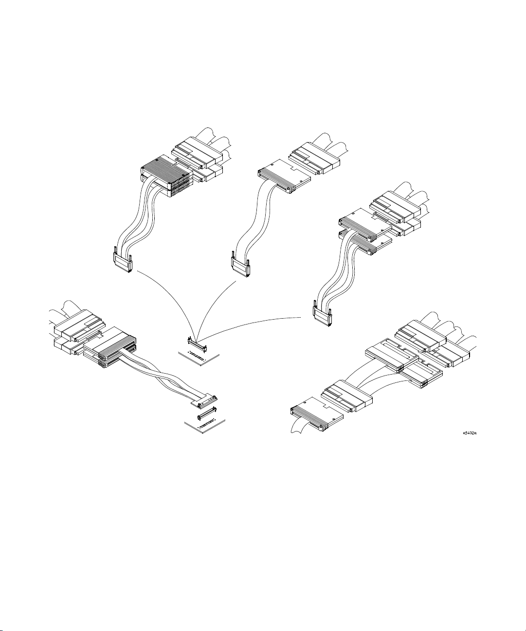
The E5400-Pro Series Soft Touch Probes — at a Glance
90-pin LA cables
E5402A-Pro
Series
Single-ended
E5412A right-angle
retention module
(34-chan)
E5404A-Pro
Series
Single-ended
40-pin LA cable
E5403A retention
module (34-chan)
E5402A,
E5405A &
E5406A-Pro
Series
90-pin LA cables
90-pin LA cables
E5405A-Pro
Series
Differential
E5406A-Pro
Series
Single-ended
16760A logic analyzer
E5386A
(used with 16760A logic
analyzer only)
8 E5400-Pro Series Soft Touch User’s Guide
Page 9

Overview, Installation, and Selection of Probing Options 1
The new Agilent E5400-pro series soft touch probes are
ultra- low-load connector- less probes that work with the
Agilent logic analysis modules. The probes attach to the PC
board using a retention module which ensures pin- to- pad
alignment and holds the probe in place.
• The E5402A- pro series probe is a low-profile right- angle
34- channel single- ended connectorless soft touch probe
(for analyzers with 90-pin cable connectors).
• The E5404A- pro series probe is a 34-channel single- ended
connectorless soft touch probe (for analyzers with 40- pin
cable connectors).
• The E5405A- pro series probe is a 17-channel differential
connectorless soft touch probe (for analyzers with 90- pin
cable connectors).
• The E5406A- pro series probe is a 34-channel
single- ended connectorless soft touch probe (for analyzers
with 90- pin cable connectors).
Use the following information to design your target system
board for use with the Agilent soft touch probes.
E5400-Pro Series Soft Touch User’s Guide 9
Page 10

1 Overview, Installation, and Selection of Probing Options
Installation Instructions
1 Use the information provided in Chapter 2 to design pads
on your board and holes for mounting the retention
module.
The soft touch probes are attached to the PC board using
a retention module which ensures pin- to- pad alignment
and holds the probe in place.
2 Use flux as necessary to clean the board and pins before
soldering the retention module to the board.
3 If your board has Organic Solder Preservative (OSP)
finish, apply solder paste to the footprint pads prior to
reflow or hand soldering.
Typically, dipped and coated finishes do not require extra
solder paste.
4 Attach the retention module to the board from either the
top or bottom of the board:
Top- side attach
Can be used with most board thicknesses.
a Insert the retention module into the board noting the
keying pin.
b Solder alignment pins from the top ensuring that solder
is added until a fillet is visible on the pin.
10 E5400-Pro Series Soft Touch User’s Guide
Page 11

Overview, Installation, and Selection of Probing Options 1
Insert
Figure 1 Solder retention module from the top.
Bottom- side attach
Can be used for board thickness of 2.54 mm (0.100 in.) or
less.
a Insert the retention module into the board noting the
keying pin.
b Solder the alignment pins to the back side of the
board.
5 Insert the probe into the retention module.
Ensure proper keying by aligning the Agilent logo on the
probe with the one on the retention module and place the
probe end into the retention module.
6 Alternate turning each screw on the probe a little until
both screws are finger tight like you would attach a cable
to your PC.
Solder pins from
top of board
E5400-Pro Series Soft Touch User’s Guide 11
Page 12

1 Overview, Installation, and Selection of Probing Options
Selection of Probing Options
This chapter provides descriptions of the logic analyzer
probes and adapters to help you select the appropriate
probe for your application. The first table shows how many
probes are required to provide connections to all channels of
your logic analyzer module. The second table gives you the
maximum state speed that is supported by the combination
of a probe and your logic analyzer module.
Tabl e 1 Number of Probes Required
Agilent Logic Analyzer Module
16753A,
Agilen t Probe
16760A
16754A,
16755A,
16756A,
16950A
1670 Series
(34ch),
1680/90 Series
(34ch)
1670 Series (68ch),
1680/90 Series
(68ch),
16715/16/17A,
16740/41/42A,
16750/51/52A&B,
16911A
1670 Series
(102ch),
1680/90 Series
(102ch),
16710/11/12A,
16910A
1670 Series
(136ch),
1680/90 Series
(136ch)
E5402A right-angle
34-channel
single-ended soft
touch probe (90-pin)
E5404A 34-channel
single-ended soft
touch probe (40-pin)
E5405A 17-channel
differential soft touch
probe (90-pin)
E5406A 34-channel
single-ended soft
touch probe (90-pin)
1 2 n/a n/a n/a n/a
n/a n/a 1 2 3 4
2 4 n/a n/a n/a n/a
1 2 n/a n/a n/a n/a
12 E5400-Pro Series Soft Touch User’s Guide
Page 13

Probe
Overview, Installation, and Selection of Probing Options 1
Tabl e 2 Maximum State Speed Supported
Logic Analyzer Module
1670 Series
16760A
16753A,
16754A,
16755A,
16756A
16950A
1680/90 Series,
16710/11/12A,
16715/16/17A,
16740/41/4A,
16750/51/52A&B 16910A/16911A
E5402A right-angle 34-channel single-ended soft
touch probe
E5404A 34-channel single-ended soft touch probe n/a n/a 400 Mb/s 500 Mb/s
E5405A 17-channel differential soft touch probe 1.5 Gb/s 800 Mb/s n/a n/a
E5406A 34-channel single-ended soft touch probe 1.5 Gb/s 800 Mb/s n/a n/a
1.5 Gb/s 800 Mb/s n/a n/a
Retention Modules
A retention module ensures pin- to- pad alignment and holds
the probe in place. A kit of five retention modules is
supplied with each probe. Additional kits (of 5) can be
ordered from Agilent Technologies at
http://www.agilent.com/find/softtouch/. If more than 5
retention modules are needed, please contact Precision
Interconnect at 10025 SW Freeman Court, Wilsonville, OR
97070, http://www.precisionint.com/, 1-503- 685- 9300.
Tabl e 3 Ordering retention modules
Probe
E5402A right-angle 34-channel single-ended soft
touch probe
Agilent Model
Number (kit of 5)
E5412A 600-0182-01
Precision Interconnect Part Number
(for volumes greater than 5)
E5404A 34-channel single-ended soft touch probe E5403A 600-0153-01
E5405A 17-channel differential soft touch probe E5403A 600-0153-01
E5406A 34-channel single-ended soft touch probe E5403A 600-0153-01
E5400-Pro Series Soft Touch User’s Guide 13
Page 14
1 Overview, Installation, and Selection of Probing Options
The E5402A-Pro Series Low-profile Right-angle 34-channel
Single-ended Soft Touch Probe
The Agilent E5402A- pro series probe is a 34-channel,
single- ended, soft touch probe compatible with the Agilent
logic analysis modules listed in Table 1 on page 12. It is
capable of capturing data up to the rated maximum state
(synchronous) analysis clock rates of all the supported
analyzers, with signal amplitudes as small as 250 mV
peak-to- peak. A retention module must be installed on the
target system board to attach the probe to the board. There
is a key on the retention module that indicates the egress of
the cable when the probe is attached.
A kit of five retention modules are supplied with each
probe. Refer to “Ordering retention modules" on page 13 for
information on ordering more.
See “Mechanical Considerations" on page 19 for
information on designing your target system board.
E5402A-pro series low-profile
right-angle 34-channel
single-ended
soft touch probe
(for analyzers with 90-pin cable connectors)
Cable egress
key
E5412A retention
module
Figure 2 E5402A-pro series right-angle single-ended soft touch probe
and E5412A retention module
14 E5400-Pro Series Soft Touch User’s Guide
Page 15

Overview, Installation, and Selection of Probing Options 1
The E5404A-Pro Series 34-channel Single-ended Soft Touch Probe
(for analyzers with 40-pin cable connectors)
The Agilent E5404A- pro series probe is a 34-channel,
single- ended, soft touch probe compatible with the Agilent
logic analysis modules listed in Table 1 on page 12. It is
capable of capturing data up to the rated maximum state
(synchronous) analysis clock rates of all the supported
analyzers, with signal amplitudes as small as 500 mV
peak-to- peak. A retention module must be installed on the
target system board to attach the probe to the board.
A kit of five retention modules are supplied with each
probe. Refer to “Ordering retention modules" on page 13 for
information on ordering more.
See “Mechanical Considerations" on page 19 for
information on designing your target system board.
E5404A-pro series
34-channel
single-ended
soft touch probe
E5403A retention
module
Figure 3 E5404A-pro series single-ended soft touch probe and
E5403A retention module
E5400-Pro Series Soft Touch User’s Guide 15
Page 16

1 Overview, Installation, and Selection of Probing Options
The E5405A-Pro Series 17-channel Differential Soft Touch Probe
(for analyzers with 90-pin cable connectors)
The Agilent E5405A- pro series probe is a 17-channel,
single- ended, soft touch probe compatible with the Agilent
logic analysis modules listed in Table 1 on page 12. It is
capable of capturing data up to the rated maximum state
(synchronous) analysis clock rates of all the supported
analyzers, with differential signal amplitudes as small as
200 mV peak- to- peak. A retention module must be installed
on the target system board to attach the probe to the board.
A kit of five retention modules are supplied with each
probe. Refer to “Ordering retention modules" on page 13 for
information on ordering more.
See “Mechanical Considerations" on page 19 for
information on designing your target system board.
Differential Input Amplitude
Definition
For differential signals, the
difference voltage Vmax - Vmin
must be greater than or equal to
200 mV p- p
E5405A-pro series
17-channel
differential
soft touch probe
E5403A retention
module
Figure 4 E5405A-pro series differential soft touch probe and
E5403A retention module
16 E5400-Pro Series Soft Touch User’s Guide
200 mV p-p
Page 17

Overview, Installation, and Selection of Probing Options 1
The E5406A-Pro Series 34-channel Single-ended Soft Touch Probe
(for analyzers with 90-pin cable connectors)
The Agilent E5406A- pro series probe is a 34-channel,
single- ended, soft touch probe compatible with the Agilent
logic analysis modules listed in Table 1 on page 12. It is
capable of capturing data up to the rated maximum state
(synchronous) analysis clock rates of all the supported
analyzers, with signal amplitudes as small as 250 mV
peak-to- peak. A retention module must be installed on the
target system board to attach the probe to the board.
A kit of five retention modules are supplied with each
probe. Refer to “Ordering retention modules" on page 13 for
information on ordering more.
See “Mechanical Considerations" on page 19 for
information on designing your target system board.
E5406A-pro series
34-channel
single-ended
soft touch probe
E5403A retention
module
Figure 5 E5406A-pro series single-ended soft touch probe and
E5403A retention module
E5400-Pro Series Soft Touch User’s Guide 17
Page 18

1 Overview, Installation, and Selection of Probing Options
The E5386A Half-channel Adapter (for use with the 16760A logic analyzer)
The E5386A Half-channel Adapter is intended to be used
with the Agilent 16760A logic analyzer in half-channel state
mode and supports the E5402A, E5405A, and E5406A
probes.
The E5386A Half-channel Adapter has its own ID code.
When using the adapter, the 16760A logic analyzer
recognizes its code rather than that of the probe which is
attached to the target. Therefore, the user interface format
menu doesn't automatically set thresholds to the proper
values. You need to go into the threshold menu and select
(differential, custom, or standard settings).
E5386A
half-channel adapter
When using the adapter in half- channel state mode:
• Clock-bits are not available in half- channel state mode
(although JCLK on the master is still used).
• Be sure to connect Master pod 1 of the logic analyzer to
the upper bits, 8- 15 + clk, on the half- channel adapter.
This is necessary to connect the clock in the system
under test to the logic analyzer system clock.
• Using the E5386A does not reduce the performance of the
16760A logic analyzer and the soft touch probes.
If the E5386A is used in full- channel state mode, the
thresholds on the unused (odd) bits are floating. This could
result in spurious activity indicators in the format menu.
18 E5400-Pro Series Soft Touch User’s Guide
Page 19

Agilent E5400-Pro Series Soft Touch Connectorless Probes
User’s Guide
2
Mechanical Considerations
Characteristics 20
Probe Dimensions 21
Board Layout Dimensions 25
Pin Outs for the Probes 28
E5386A Half-channel Adapter Dimensions 36
Use the following mechanical information to design your
target system board.
A
19
Page 20

2 Mechanical Considerations
Characteristics
Electrical considerations such as equivalent probe loads,
input impedance, and time domain transmission are shown
in chapters 3 and 4 of this manual. Other characteristics are
dependant on the logic analyzer module you are using.
20 E5400-Pro Series Soft Touch User’s Guide
Page 21
Probe Dimensions
Top view E5402A
Mechanical Considerations 2
The following figures show the dimensions of the Agilent
E5400- pro series soft touch probes.
Side view E5402A
Figure 6 E5402A probe dimensions
E5400-Pro Series Soft Touch User’s Guide 21
Page 22

2 Mechanical Considerations
Top view E5404A
Side view E5404A
Figure 7 E5404A probe dimensions
22 E5400-Pro Series Soft Touch User’s Guide
Page 23

Top view E5405A
Mechanical Considerations 2
Side view E5405A
Figure 8 E5405A probe dimensions
E5400-Pro Series Soft Touch User’s Guide 23
Page 24

2 Mechanical Considerations
Top view E5406A
Side view E5406A
Figure 9 E5406A probe dimensions
24 E5400-Pro Series Soft Touch User’s Guide
Page 25

Board Layout Dimensions
Retention Module Dimensions
Mechanical Considerations 2
Use the following dimensions to layout your PC board pads
and holes for use with the soft touch probes.
4.01 mm
0.158 in.
Figure 10 E5403A retention module dimensions
Figure 11 E5412A retention module dimensions
E5400-Pro Series Soft Touch User’s Guide 25
Page 26

2 Mechanical Considerations
Figure 12 E5403A side-by-side dimensions
Optimal board thickness for this top- side mount retention
module is shown above. Retention modules can be hand
soldered into thicker boards, but will not form a bottom- side
solder fillet.
Figure 13 E5412A side-by-side dimensions
26 E5400-Pro Series Soft Touch User’s Guide
Page 27

Footprint Dimensions
The retention module alignment is symetrical around the
pad footprint.
Mechanical Considerations 2
B1
A1
B1
A1
B27
A27
B27
A27
Figure 14 Top view footprint dimensions (drawing notes next page).
NOTE
The above view is looking down onto the footprint on the printed-circuit
board.
E5400-Pro Series Soft Touch User’s Guide 27
Page 28

2 Mechanical Considerations
Pin Outs for the Probes
Drawing notes:
1 Maintain a solder mask web between pads when traces are routed between
the pads on the same layer. The solder mask may not encroach onto the pads
within the pad dimension shown.
2 VIAs not allowed on these pads. VIA edges may
be tangent to pad edges as long as a solder mask
web between VIAs and pads is maintained.
3 Surface finishes on pads should be HASL
immersion silver, or gold over nickel.
4 This footprint is compatible with retention
module Agilent model number E5403A.
5 Plated through hole should not be tied to ground plane for thermal relief.
VIA
Pad
NOTE
If you will be using the soft touch probes with a 16900-series logic
analyzer running V2.5 or higher, probe types can be defined in XML
configuration files. To get the latest Probes.xml file, go to
www.agilent.com/find/probe-definitions
Files\Agilent Technologies\AddIns\Agilent\. Refer to the logic analyzer
on-line help for more information.
. Install the file in c:\Program
28 E5400-Pro Series Soft Touch User’s Guide
Page 29

Probing with E5404A-Pro Series Probe
r
The following footprint provides pin out and pad numbers
for the E5404A single- ended probe for use with 40- pin logic
analyzers.
A1
D0
A2
D1
A3
GND
A4
D4
A5
D5
A6
GND
GND
D10
D11
GND
D14
D15
GND
D2
D3
GND
D6
D7
GND
D8
D9
GND
D12
D13
GND
A7
A8
*
A9
A10
A11
A12
A13
A14
A15
A16
A17
A18
A19
A20
A21
A22
A23
A24
A25
A26
A27
CK 1+
Logic
analyzer
even pod
Mechanical Considerations 2
GND
B1
D2
B2
D3
B3
GND
B4
D6
B5
B6
B7
B8
B9
B10
B11
B12
B13
B14
B15
B16
B17
B18
B19
B20
B21
B22
B23
B24
B25
B26
B27
D7
GND
D8
D9
GND
D12
D13
GND
D0
D1
GND
D4
D5
GND
*
CK 2+
GND
D10
D11
GND
D14
D15
Logic
analyze
odd pod
Figure 15 Pad numbers for E5404A-pro series.
* If you only plan to use the E5404A 40-pin probe with
single- ended clocking to probe the following footprint, then
A8 and B20 are unused. They can be grounded, not
connected, left floating, or driven. These pads are not
probed with the E5404A probe.
E5400-Pro Series Soft Touch User’s Guide 29
Page 30

2 Mechanical Considerations
If you ever plan on upgrading from a 40-pin to a 90- pin
logic analyzer to take advantage of higher state speed and
differential probing on the clock channel, some steps should
be taken so that the original footprint will work for both the
E5404A and the E5406A probes.
• If you are driving only single- ended clocks into A7
(CK1+) and B21 (CK2+), then you should ground A8
and B20. A8 and B20 are where CK1- and CK2- are
driven in the E5406A probe. Grounding these pads will
allow the user- defined threshold in the analyzer to be
used as in normal single- ended operation.
• If you are using differential clocks, route the Odd pod
clock such that the positive side of the pair goes to A7
(CK1+) and the negative side of the pair goes to A8
(CK1- ). Similarily, route the Even pod clock such that
the positive side of the pair goes to B21 (CK2+) and
the negative side of the pair goes to B20 (CK2- ). When
using the E5404A probe, A8 and B20 are unused.
However, when using the E5406A probe, A8 and B20
are where the probe connects to the negative sides of
the clocks' differential pair.
30 E5400-Pro Series Soft Touch User’s Guide
Page 31

Mechanical Considerations 2
E5404A 34-channel
Single-ended Probe Logic Analyzer
Signal Name Pad # Channel Pod Signal Name Pad # Channel Pod
D0 A1
D1 A2
Ground A3 D3 B3 → 3
D4 A4 → 4GroundB4
D5 A5
Ground A6 D7 B6
Clock 1+ A7 → Clock Ground B7
GND/NC/
Clock 1Ground A9 D9 B9
D10 A10
D11 A11
Ground A12 D13 B12
D14 A13
D15 A14
Ground A15 Whichever
D2 A16
D3 A17
Ground A18 D5 B18
D6 A19
D7 A20
Ground A21 Clock 2+ B21
D8 A22
D9 A23
Ground A24 D11 B24
D12 A25
D13 A26
Ground A27 D15 B27
A8
→ 0 Whichever
→ 1D2B2→ 2
→ 5D6B5→ 6
pod is
connected
to "Odd" on
the E5404A
probe
→ See *
pg 29
→ 10 Ground B10
→ 11 D12 B11 → 12
→ 14 Ground B13
→ 15 D0 B14 → 0 Whichever
→ 2GroundB16
→ 3D4B17→ 4
→ 6GroundB19
pod is
connected
to "Even"
on the
E5404A
probe
→ 7Ground/NC
→ 8GroundB22
→ 9D10B23→ 10
→ 12 Ground B25
→ 13 D14 B26 → 14
E5404A 34-channel
Single-ended Probe Logic Analyzer
Ground B1 Whichever
pod is
connected
to "Odd" on
the E5404A
probe
→ 7
D8 B8 → 8
→ 9
→ 13
D1 B15
B20 → See *
/Clock 2-
→ 1
→ 5
pg 29
pod is
connected
to "Even"
on the
E5404A
probe
→ Clock
→ 11
→ 15
E5400-Pro Series Soft Touch User’s Guide 31
Page 32

2 Mechanical Considerations
+
+
+
+
Probing with the E5405A-Pro Series Probe
The following footprint provides pin out and pad numbers
for the E5405A differential probe for use with 90-pin logic
analyzers.
A1
D0+
D0-
GND
D2+
D2-
GND
D4+
D4-
GND
D6+
D6-
GND
NC
NC
GND
D8+
D8-
GND
D10+
D10GND
D12+
D12GND
D14+
D14GND
A2
A3
A4
A5
A6
A7
A8
A9
A10
A11
A12
A13
A14
A15
A16
A17
A18
A19
A20
A21
A22
A23
A24
A25
A26
A27
B1
B2
B3
B4
B5
B6
B7
B8
B9
B10
B11
B12
B13
B14
B15
B16
B17
B18
B19
B20
B21
B22
B23
B24
B25
B26
B27
GND
D1D1+
GND
D3D3+
GND
D5D5+
GND
D7D7+
GND
CLKCLK
GND
D9D9+
GND
D11D11
GND
D13D13
GND
D15D15
Figure 16 Pad numbers for E5405A-pro series.
32 E5400-Pro Series Soft Touch User’s Guide
Page 33

Mechanical Considerations 2
E5405A Differential
Probe
Signal Name Pad# Channel Pod Signal Name Pad# Channel Pod
D0 (+) A1
D0 (-)A2 D1 (-)B2
Ground A3 D1 (+) B3
D2 (+) A4
D2 (-)A5 D3 (-)B5
Ground A6 D3 (+) B6
D4 (+) A7
D4 (-)A8 D5 (-)B8
Ground A9 D5 (+) B9
D6 (+) A10
D6 (-) A11 D7 (-) B11
Ground A12 D7 (+) B12
NC A13 Ground B13
NC A14 Clock - B14
GND A15 Clock + B15
D8 (+) A16
D8 (-) A17 D9 (-) B17
Ground A18 D9 (+) B18
D10 (+) A19
D10 (-) A20 D11 (-) B20
Ground A21 D11 (+) B21
D12 (+) A22
D12 (-) A23 D13 (-) B23
Ground A24 D13 (+) B24
D14 (+) A25
D14 (-) A26 D15 (-) B26
Ground A27 D15 (+) B27
→ 0 Whichever
→ 2GroundB4
→ 4GroundB7
→ 6GroundB10
→ 8GroundB16
→ 10 Ground B19
→ 12 Ground B22
→ 14 Ground B25
Logic Analyzer E5405A Differential
Probe
Ground B1 Whichever
pod is
plugged
into the
E5405A
probe
Logic Analyzer
→ 1
→ 3
→ 5
→ 7
→ Clock
→ 9
→ 11
→ 13
→ 15
pod is
plugged
into the
E5405A
probe
E5400-Pro Series Soft Touch User’s Guide 33
Page 34

2 Mechanical Considerations
r
Probing with the E5402A/E5406A-Pro Series Probe
The following footprint provides pin out and pad numbers
for the E5402A/E5406A single- ended probe for use with
90- pin logic analyzers.
A1
Logic
analyzer
even pod
D0
D1
GND
D4
D5
GND
CK 1+
*GND/CK1-
GND
D10
D11
GND
D14
D15
GND
D2
D3
GND
D6
D7
GND
D8
D9
GND
D12
D13
GND
A2
A3
A4
A5
A6
A7
A8
A9
A10
A11
A12
A13
A14
A15
A16
A17
A18
A19
A20
A21
A22
A23
A24
A25
A26
A27
B1
B2
B3
B4
B5
B6
B7
B8
B9
B10
B11
B12
B13
B14
B15
B16
B17
B18
B19
B20
B21
B22
B23
B24
B25
B26
B27
GND
D2
D3
GND
D6
D7
GND
D8
D9
GND
D12
D13
GND
D0
D1
GND
D4
D5
GND
*GND/CK 2CK 2+
GND
D10
D11
GND
D14
D15
Logic
analyze
odd pod
Figure 17 Pad numbers for E5402/E5406A-pro series
34 E5400-Pro Series Soft Touch User’s Guide
Page 35

Mechanical Considerations 2
E5402A/E5406A
34-channel
Single-ended Probe
Signal Name Pad # Channel Pod Signal Name Pad # Channel Pod
D0 A1
D1 A2
Ground A3 D3 B3 → 3
D4 A4 → 4GroundB4
D5 A5
Ground A6 D7 B6 → 7
Clock 1+ A7 → Clock Ground B7
GND/
Clock 1Ground A9 D9 B9
D10 A10
D11 A11
Ground A12 D13 B12
D14 A13
D15 A14
Ground A15 Whichever
D2 A16
D3 A17
Ground A18 D5 B18
D6 A19
D7 A20
Ground A21 Clock 2+ B21
D8 A22
D9 A23
Ground A24 D11 B24
D12 A25
D13 A26
Ground A27 D15 B27
A8
→ 0 Whichever
→ 1D2B2→ 2
→ 5D6B5→ 6
→ Clock D8 B8 → 8
→ 10 Ground B10
→ 11 D12 B11 → 12
→ 14 Ground B13
→ 15 D0 B14 → 0 Whichever
→ 2GroundB16
→ 3D4B17→ 4
→ 6GroundB19
→ 7Ground/
→ 8GroundB22
→ 9D10B23→ 10
→ 12 Ground B25
→ 13 D14 B26 → 14
Logic Analyzer
pod is
connected
to "Odd" on
the 5402A/
E5406A
probe
pod is
connected
to "Even"
on the
E5402A/
E5406A
probe
E5402A/E5406A
34-channel
Single-ended Probe
Ground B1 Whichever
Logic Analyzer
pod is
connected
to "Odd" on
the E5402/
E5406A
probe
→ 9
→ 13
D1 B15
B20 → Clock
Clock 2-
→ 1
→ 5
pod is
connected
to "Even"
on the
E5402A/
E5406A
probe
→ Clock
→ 11
→ 15
E5400-Pro Series Soft Touch User’s Guide 35
Page 36

2 Mechanical Considerations
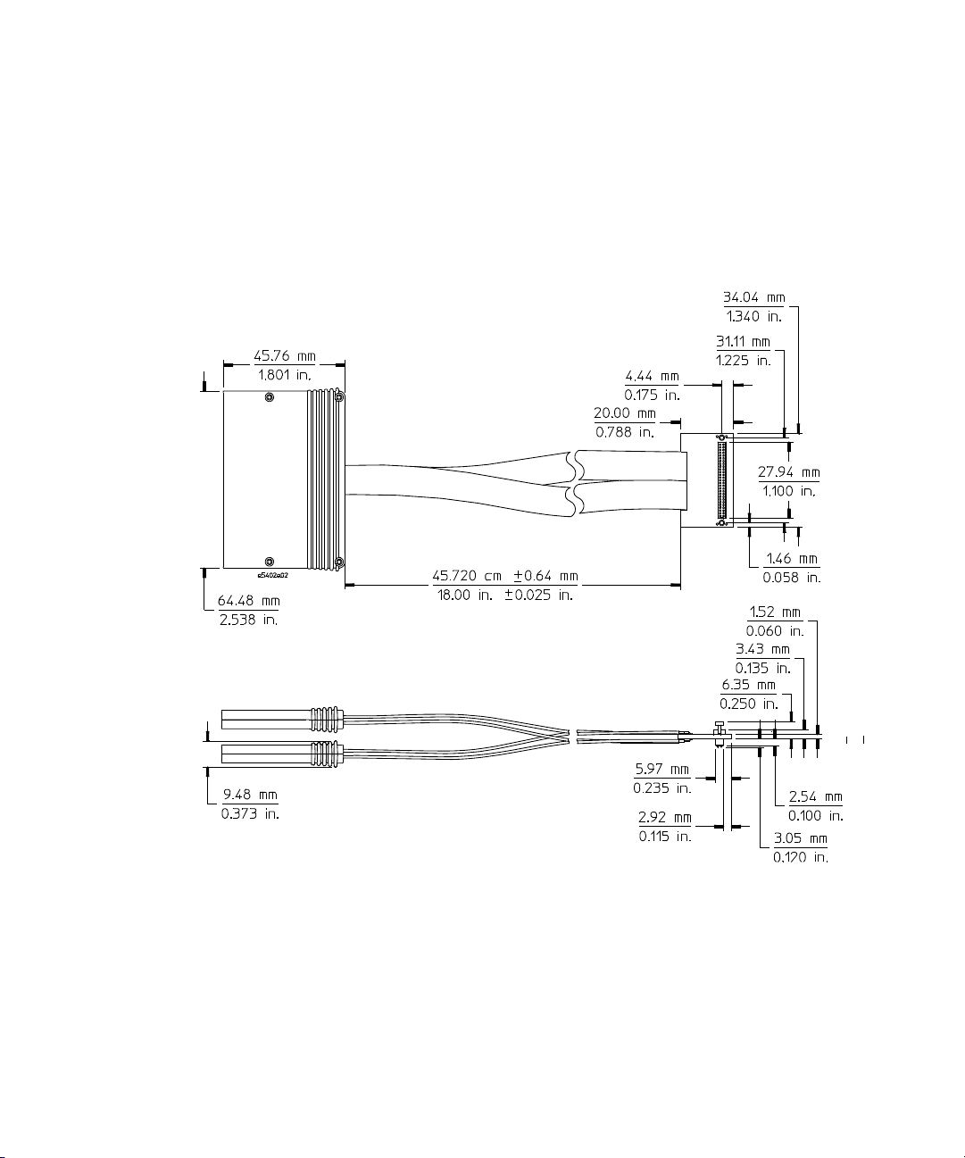
E5386A Half-channel Adapter Dimensions
The E5386A half- channel adapter works with the 16760A
logic analyzer and the soft touch probes.
Figure 18 E5386A dimensions
36 E5400-Pro Series Soft Touch User’s Guide
Page 37

Mechanical Considerations 2
Pin out for the E5386A half-channel adapter when connected to E5405A
When used with the E5405A- pro series differential soft
touch probe, you need only one half-channel adapter. The
table below shows the pin assignments.
Logic analyzer pods
(16760A only)
E5386A half-channel
adapter
E5405A differential probe
Figure 19 Half-channel adapter with E5405A-pro series
Tabl e 4 Pin-out table for E5386A connected to an E5405A
E5405A Differential Probe
Negative Signals
Signal Name Pin# Signal Name Pin# Channel Pod
D0(-) A2 D0(+) A1
D1(-) B2 D1(+) B3
D2(-) A5 D2(+) A4
D3(-) B5 D3(+) B6
D4(-) A8 D4(+) A7
D5(-) B8 D5(+) B9
D6(-) A11 D6(+) A10
D7(-) B11 D7(+) B12
E5400-Pro Series Soft Touch User’s Guide 37
Positive Signals Logic Analyzer
→ 0 Whichever
→ 2
→ 4
pod is
plugged
into bits 0-7
→ 6
→ 8
→ 10
→ 12
→ 14
Page 38

2 Mechanical Considerations
Signal Name Pin# Signal Name Pin# Channel Pod
Pin out for two E5386A half-channel adapters connected to one E5402A
The E5386A that is connected to the end
of the E5402A/E5406A labeled ‘odd’
becomes the ‘odd’ E5386A adapter.
or E5406A
E5405A Differential Probe
Negative Signals
D8(-) A17 D8(+) A16 → 0 Whichever
D9(-) B17 D9(+) B18
D10(-) A20 D10(+) A19
D011(-) B20 D11(+) B21
D12(-) A23 D12(+) A22
D13(-) B23 D13(+) B24
D14(-) A26 D14(+) A25
D15(-) B26 D15(+) B27
D16(-)/Clk(-) B14 D16(+)/Clk(+) B15
Positive Signals Logic Analyzer
→ 2
→ 4
→ 6
pod is
plugged
into bits
8-15
→ 8
→ 10
→ 12
→ 14
→ Clock
When used with the E5402A/E5406A- pro series single- ended
soft touch probe, you need two half-channel adapters, one
adapter for Odd data and one for Even data. The table
below shows the pin assignments.
Logic analyzer pods
(16760 only)
E5386 half-channel
adapters
E5402A/E5406A
single-ended
probe
Odd
Even
Figure 20 Two half-channel adapters with E5402A/E5406A-pro series
38 E5400-Pro Series Soft Touch User’s Guide
Page 39

Mechanical Considerations 2
Tabl e 5 Pin-out table for two E5386A adapters connected to an E5402A
or E5406A
E5386A Adapter Odd E5386A Adapter Even
E5402A/E5406A
34-channel
Single-ended Probe
Signal Name Pin # Channel Pod Signal Name Pin # Channel Pod
D0 A1
D1 A2
D2 B2 → 4D2A16→ 4
D3 B3
D4 A4
D5 A5 → 10 D5 B18 → 10
D6 B5
D7 B6
D8 B8 → 0 Whichever
D9 B9
D10 A10
D11 A11 → 6D11B24→ 6
D12 B11
D13 B12
D14 A13 → 12 D14 B26 → 12
D15 A14
D16(+)/Clk(+)
D16(-)/Clk(-) A8
→ 0 Whichever
→ 2D1B15→ 2
→ 6D3A17→ 6
→ 8D4B17→ 8
→ 12 D6 A19 → 12
→ 14 D7 A20 → 14
→ 2D9A23→ 2
→ 4D10B23→ 4
→ 8D12A25→ 8
→ 10 D13 A26 → 10
→ 14 D15 B27 → 14
A7 → Clock(+)
→ Clock(-) D16(-)/Clk(-) B20 → Clock(-)
Logic Analyzer
pod is
connected to
bits 0-7 on
the odd
E5386A
pod is
connected to
bits 8-15 on
the odd
E5386A
E5402A/E5406A
34-channel
Single-ended Probe
D0 B14
D8 A22
D16(+)/Clk(+)
B21 → Clock(+)
Logic Analyzer
→ 0 Whichever
→ 0 Whichever
pod is
connected to
bits 0-7 on
the even
E5386A
pod is
connected to
bits 8-15 on
the even
E5386A
E5400-Pro Series Soft Touch User’s Guide 39
Page 40

2 Mechanical Considerations
40 E5400-Pro Series Soft Touch User’s Guide
Page 41

Agilent E5400-Pro Series Soft Touch Connectorless Probes
User’s Guide
3
Operating the E5404A-Pro Series
Probes
Equivalent Probe Loads 42
Time Domain Transmission (TDT) 44
Electrical considerations such as equivalent probe loads,
input impedance, and time domain transmission (TDT).
A
41
Page 42

3 Operating the E5404A-Pro Series Probes
Equivalent Probe Loads
The following probe load models are based on in-circuit
measurements made with an Agilent 8753E 6 GHz network
analyzer and an Agilent 54750A TDR/TDT using a 50 Ω test
fixture. The following schematic accurately models the probe
load out to 6 GHz. The figure on the following page shows
the agreement between measured impedance and this model.
(Does not include capacitive coupling between channels or inductance of the spring pins)
Din
Cstub
0.375pF
(Includes capacitive coupling between channels and inductance of spring pins.)
Simple
Rtap
400Ω
Complex
Rtip
100kΩ
Ctip
10pF
Din
42 E5400-Pro Series Soft Touch User’s Guide
Lspring1
0.63nH
Ccoupling
0.070pF
Figure 21 Probe load models (E5404A)
Lspring2
1.17nH
Cstub
0.375pF
Rgnd1
10Ω
Rtip1
250Ω
Rtip2
100kΩ
Ctip
10pF
Rgnd2
120Ω
Page 43

Operating the E5404A-Pro Series Probes 3
)
5
1
10
8
6
4
2
1
8
6
4
Ohms
2
1
8
6
4
2
1
8
6
4
10
9
68
1247
100k 1M 10M 100M 1G
68
9
5
7
3
124
56 8
3
9
7
124
Frequency
7
3568
9
124
568124
3
Modeled
(simple)
9
7
Measured
3
Modeled
(complex
5
6
Figure 22 Measured versus modeled input impedance (E5404A)
E5400-Pro Series Soft Touch User’s Guide 43
Page 44

3 Operating the E5404A-Pro Series Probes
Time Domain Transmission (TDT)
All probes have a loading effect on the circuit when they
come in contact with the circuit. Time domain transmission
(TDT) measurements are useful for understanding the probe
loading effects as seen at the target receiver. The following
TDT measurements were made mid-bus on a 50Ω
transmission line load terminated at the receiver. These
measurements show how the soft touch probes affect an
ideal step seen by the receiver for various rise times.
Figure 23 TDT measurement schematic (E5404A)
The following plots were made on an Agilent 54750A
oscilloscope using TDT.
44 E5400-Pro Series Soft Touch User’s Guide
Page 45

50 mV per division
Operating the E5404A-Pro Series Probes 3
without probe
with probe
500 ps per division
Figure 24 TDT measurement at receiver with and without probe load for
150 ps rise time
without probe
with probe
50 mV per division
500 ps per division
Figure 25 TDT measurement at receiver with and without probe load for
250 ps rise time
E5400-Pro Series Soft Touch User’s Guide 45
Page 46

3 Operating the E5404A-Pro Series Probes
50 mV per division
Figure 26 TDT measurement at receiver with and without probe load for
without probe
with probe
500 ps per division
500 ps rise time
without probe
with probe
50 mV per division
500 ps per division
Figure 27 TDT measurement at receiver with and without probe load for
1000 ps rise time
46 E5400-Pro Series Soft Touch User’s Guide
Page 47

Agilent E5400-Pro Series Soft Touch Connectorless Probes
User’s Guide
4
Operating the E5402A, E5405A, and
E5406A-Pro Series Probes
Equivalent Probe Loads 48
Time Domain Transmission (TDT) 50
Step Inputs 53
Eye Opening 56
Electrical considerations such as equivalent probe loads,
input impedance, time domain transmission (TDT), step
inputs, and eye opening.
A
47
Page 48

4 Operating the E5402A, E5405A, and E5406A-Pro Series Probes
Equivalent Probe Loads
The following probe load models are based on in-circuit
measurements made with an Agilent 8753E 6 GHz network
analyzer and an Agilent 54750A TDR/TDT using a 50 Ω test
fixture. The following schematic accurately models the probe
load out to 6 GHz. The figure on the following page shows
the agreement between measured impedance and this model.
PC board pads are not included.
Cshnt1
.350pF
D1
Cm12
0.070pF
D0
L11
0.63nH
L21
0.63nH
C12
0.280pF
Rgnd1
0.5Ω
C22
0.280pF
Rgnd2
0.5Ω
L12
1.17nH
L22
1.17nH
Rtip1
20KΩ
Cshnt2
.350pF
Rtip2
20KΩ
Rtrm1
75Ω
+0.75V
Rtrm2
75Ω
+0.75V
Figure 28 Probe load model (E5402A, E5405A, and E5406A)
48 E5400-Pro Series Soft Touch User’s Guide
Page 49

Operating the E5402A, E5405A, and E5406A-Pro Series Probes 4
2
q
y
6
4
10
1
8
6
4
2
1
8
6
4
Ohms
2
1
8
6
4
Measured
Model
2
10
1
68
9
1247
10 0 k
56 8
79 3 56 8
3
124
1 M 10 M 100 M 1 G
79 3 568
124
uenc
Fre
9
7
124
3
56 8 1 2 47
9
5
3
Figure 29 Measured versus modeled input impedance (E5402A,
E5404A, and E5406A)
E5400-Pro Series Soft Touch User’s Guide 49
Page 50

4 Operating the E5402A, E5405A, and E5406A-Pro Series Probes
Time Domain Transmission (TDT)
All probes have a loading effect on the circuit when they
come in contact with the circuit. Time domain transmission
(TDT) measurements are useful for understanding the probe
loading effects as seen at the target receiver. The following
TDT measurements were made mid-bus on a 50Ω
transmission line load terminated at the receiver. These
measurements show how the E5402A, E5405A, and
E5406A- pro series soft touch probes affect an ideal step
seen by the receiver for various rise times.
Figure 30 TDT measurement schematic (E5402A, E5405A, and E5406A)
The following plots were made on an Agilent 54750A
oscilloscope using TDT.
50 E5400-Pro Series Soft Touch User’s Guide
Page 51

50 mV per division
Operating the E5402A, E5405A, and E5406A-Pro Series Probes 4
without probe
with probe
500 ps per division
Figure 31 TDT measurement at receiver with and without probe load for
100 ps rise time
without probe
with probe
50 mV per division
500 ps per division
Figure 32 TDT measurement at receiver with and without probe load for
250 ps rise time
E5400-Pro Series Soft Touch User’s Guide 51
Page 52

4 Operating the E5402A, E5405A, and E5406A-Pro Series Probes
without probe
50 mV per division
500 ps per division
Figure 33 TDT measurement at receiver with and without probe load for
500 ps rise time
with probe
without probe
with probe
50 mV per division
500 ps per division
Figure 34 TDT measurement at receiver with and without probe load for
1000 ps rise time
52 E5400-Pro Series Soft Touch User’s Guide
Page 53

Step Inputs
Operating the E5402A, E5405A, and E5406A-Pro Series Probes 4
Maintaining signal fidelity to the logic analyzer is critical if
the analyzer is to accurately capture data. One measure of a
system's signal fidelity is to compare V
step inputs. For the following graphs, V
logic analyzer probe tip. Eye Scan was used to measure V
to V
in
is the signal at the
in
for various
out
out
the signal seen by the logic analyzer. The measurements
were made on a mid-bus connection to a 50Ω transmission
line load terminated at the receiver. These measurements
show the logic analyzer's response while using the E5402A,
E5405A, and E5406A- pro series soft touch probes.
,
Logic
Analyzer
w/ EyeScan
E5382A
Probe
Driver Receiver
Rsource
50 Ω
Step
output
Z0=5 0 Ω
54701A
Probe
Z0=50 Ω
Oscilloscope
2.5GHz BW
incl. probe
Rterm
50 Ω
Figure 35 Step input measurement schematic (E5402A, E5405A, and
E5406A)
The following plots were made on an Agilent 54750A
oscilloscope and an Agilent 16760A logic analyzer using an
Agilent 8133A pulse generator with various rise time
converters.
E5400-Pro Series Soft Touch User’s Guide 53
Page 54

4 Operating the E5402A, E5405A, and E5406A-Pro Series Probes
EyeScan
Scope
100 mV per division
500 ps per division
Figure 36 Logic analyzer’s response to 150 ps rise time
EyeScan
Scope
100 mV per division
500 ps per division
Figure 37 Logic analyzer’s response to 250 ps rise time
54 E5400-Pro Series Soft Touch User’s Guide
Page 55

100 mV per division
Operating the E5402A, E5405A, and E5406A-Pro Series Probes 4
EyeScan
Scope
500 ps per division
Figure 38 Logic analyzer’s response to 500 ps rise time
EyeScan
Scope
100 mV per division
500 ps per division
Figure 39 Logic analyzer’s response to 1000 ps rise time
E5400-Pro Series Soft Touch User’s Guide 55
Page 56

4 Operating the E5402A, E5405A, and E5406A-Pro Series Probes
Eye Opening
The eye opening at the logic analyzer is the truest measure
of an analyzer's ability to accurately capture data. Seeing the
eye opening at the logic analyzer is possible with Eye Scan.
The eye opening viewed with Eye Scan helps the user know
how much margin the logic analyzer has, where to sample
and at what threshold. Any probe response that exhibits
overshoot, ringing, probe non-flatness, noise, and other
issues all deteriorate the eye opening seen by the logic
analyzer. The following eye diagrams were measured using
E5402A, E5405A, and E5406A- pro series soft touch probes
and Eye Scan while probed mid-bus on a 50Ω transmission
line load terminated at the receiver. The data patterns were
generated using a 2
Logic
Analyzer
w/ EyeScan
23
E5382A
Probe
- 1 pseudo random bit sequence (PRBS).
Driver Receiver
Rsource
50 Ω
PRBS
output
Z0=5 0 Ω
Z0=50 Ω
Rterm
50 Ω
Figure 40 Eye opening measurement schematic (E5402/05/06A)
The following plots were made on an Agilent 16760A logic
analyzer using an Agilent 8133A pulse generator with a
250 ps rise time converter. The following measurements use
Eye Scan to show the margin at 800, 1250, and 1500MT/s.
The amplitudes are indicated in the captions.
56 E5400-Pro Series Soft Touch User’s Guide
Page 57

100 mV per division
Operating the E5402A, E5405A, and E5406A-Pro Series Probes 4
500 ps per division
Figure 41 Logic analyzer eye opening for a PRBS signal of 500 mV p-p,
800 MT/s data rate
100 mV per division
500 ps per division
Figure 42 Logic analyzer eye opening for a PRBS signal of 500 mV p-p,
1250 MT/s data rate
E5400-Pro Series Soft Touch User’s Guide 57
Page 58

4 Operating the E5402A, E5405A, and E5406A-Pro Series Probes
100 mV per division
500 ps per division
Figure 43 Logic analyzer eye opening for a PRBS signal of 500 mV p-p,
1500 MT/s data rate
100 mV per division
500 ps per division
Figure 44 Logic analyzer eye opening for a PRBS signal of 200 mV p-p,
1500 MT/s data rate
58 E5400-Pro Series Soft Touch User’s Guide
Page 59

Agilent Soft Touch Pro Connectorless Probes
User’s Guide
5
Circuit Board Design
Transmission Line Considerations 60
Recommended Routing 61
Data and Clock Inputs per Operating Mode 63
Thresholds 66
Signal Access 67
Design considerations when you layout your circuit board.
A
59
Page 60

5 Circuit Board Design
Transmission Line Considerations
Stubs connecting signal transmission lines to the connector
should be as short as feasible. Longer stubs will cause more
loading and reflections on a transmission line. If the
electrical length of a stub is less than 1/5 of the signal rise
time, it can be modeled as a lumped capacitance. Longer
stubs must be treated as transmission lines.
Example: Assume you are using FR- 4 PC board material with a
dielectric constant of ~4.3 for inner-layer traces (stripline).
For example, A 0.28 cm long stub in an inner layer has a
propagation delay of ~20 ps. Therefore, for a signal with a
rise time of 100 ps or greater, a 0.28 cm stub will behave
like a capacitor.
The trace capacitance per unit length will depend on the
trace width and the spacing to ground or power planes. If
the trace is laid out to have a characteristic impedance of
50 Ω it turns out that the capacitance per unit length is
~1.2 pF/cm. Therefore the 0.28 cm stub in the previous
example would have an effective capacitance equal to
~0.34 pF.
This trace capacitance is in addition to the probe load
model.
60 Soft Touch Pro User’s Guide
Page 61

Recommended Routing
Circuit Board Design 5
Two rows of compliant contacts in the probe make contact
with pads laid down on the surface of the PC board. These
contacts provide an extremely low probe load (<0.70 pF per
channel), and make a good electrical connection with a small
amount of compression force on a choice of standard PCB
platings. Additionally, the pin contact points are free from
the contamination effects that plague other connector- less
probing technologies.
B1A1
D0
D1
D2
D3
D4
D5
D6
D7
CK1+
CK1D8
D9
D10
D11
D12
D13
D14
D15
D0
D1
D2
D3
D4
D5
D6
D7
CK2-
CK2+
D8
D9
D10
D11
D12
D13
D14
D15
B27A27
ODD POD EVEN POD
Figure 45 34-bit single-ended routing (E5402A, E5404A, and E5406A)
Soft Touch Pro User’s Guide 61
Page 62

5 Circuit Board Design
B1A1
+
D0
-
-
D1
+
+
D2
-
-
D3
+
+
D4
-
-
D5
+
+
D6
-
-
D7
+
-
CK
+
+
D8
-
-
D9
+
+
D10
-
-
D11
+
+
D12
-
-
D13
+
+
D14
-
-
D15
+
B27A27
Figure 46 17-bit differential routing (E5405A)
62 Soft Touch Pro User’s Guide
Page 63

Data and Clock Inputs per Operating Mode
The following table shows the number of data and clock
inputs for each connector on your target system for the
various operating modes of your logic analyzer.
Tabl e 6 16760A logic analyzer
Circuit Board Design 5
Operating
Mode
Synchronous
(state)
analysis
200 Mb/s,
400 Mb/s,
800 Mb/s
Synchronous
(state)
analysis
1250 Mb/s
1500 Mb/s
Eye scan mode
800 Mb/s
Eye scan mode
1500 Mb/s
E5405A
17-channel
differential
soft touch
16 data
plus 1 clock
input (see
note 1)
8 data
plus 1 clock
input (see
note 2)
16 data
plus 1 clock
input (see
note 1)
8 data
plus 1 clock
input (see
note 2)
E5402A or
E5406A
E5405A with
half-channel
adapter E5386A
N/A 32 data
16 data
plus 1 clock
input
(see note 2)
N/A 32 data
16 data
plus 1 clock
input
(see note 2)
34-channel
single-ended
soft touch
plus 2 clock
inputs
(see note 1)
16 data
plus 1 clock
input
(see note 2)
plus 2 clock
inputs
(see note 1)
16 data
plus 1 clock
input
(see note 2)
E5402A or
E5406A with
half-channel
adapter E5386A
N/A
16 data
plus 1 clock
input
(see note 2)
N/A
16 data
plus 1 clock
input
(see note 2)
Timing mode 16 data
plus 1 clock
input (see
note 3)
N/A 32 data
plus 2 clock
inputs
(see note 3)
N/A
Soft Touch Pro User’s Guide 63
Page 64

5 Circuit Board Design
Note 1: In the 200 Mb/s, 400 Mb/s, and 800 Mb/s synchronous (state) analysis
modes, and the 800 Mb/s eye scan mode, there is one clock input which must
be routed to the clock input on pod 1 (of the master module, in a multi-card set).
The clock inputs on other pods can be assigned to labels and acquired as data
inputs.
Note 2: In the 1250 Mb/s and 1500 Mb/s synchronous (state) analysis modes, and
in the 1500 Mb/s eye scan mode, the clock inputs on other pods cannot be assigned to labels and acquired as data inputs.
Note 3: In asynchronous (timing) analysis, all inputs including clocks can be ac-
quired and assigned to labels.
- To realize 17 data inputs (in full-channel mode) while using time tags in addition
to a clock input on a single 16760A module or on the master module in a
multi-card set, you must route the data signals to pod 2 and the clock to pod 1. A
convenient way to avoid laying out a second connector to connect only the clock
signal is to use the Agilent E5382A flying-lead set to make the connection to the
clock.
- To use the qualifier input for eye scan, the qualifier signal must be routed to the
clock input on pod 2 (K clock), and the clock must be routed to the clock input on
pod 1 (J clock), each on the master module in case of a multi-card set.
- In a multiple-card set, the clock used for synchronous (state) analysis must be
routed to the clock input on pod 1 of the master module. On a single card, the
clock must be routed to the clock input on pod 1.
64 Soft Touch Pro User’s Guide
Page 65

Circuit Board Design 5
Tabl e 7 16753/54/55/56A and 16950A logic analyzers
E5402A or E5406A
Operating Mode
E5405A 17-channel
differential soft touch
34-channel
single-ended soft touch
Synchronous
(state) analysis
300 Mb/s
800 Mb/s,
Eye scan mode
300 Mb/s
600 Mb/s
Timing mode 16 data plus 1 clock input
Note 1: In 600 Mb/s mode, there is one clock input which must be routed to the
clock input on pod 1 of the master module in a multi-card set. The clock inputs
on the other pods can be assigned to labels and acquired as data inputs.
16 data plus 1 clock input
(see note 1)
16 data plus 1 clock input
(see note 1)
(see note 1)
32 data plus 2 clock inputs
(see note 1)
32 data plus 2 clock inputs
(see note 1)
32 data plus 2 clock inputs
(see note 3)
Tabl e 8 1670 Series, 1680/90 Series, 16710/11/12A, 16715/16/17A,
16740/41/4A, 16750/51/52B, 16910/11A logic analyzers
E5404A 34-channel
Operating Mode
Synchronous (state) analysis
250 Mb/s, 500 Mb/s,
Timing mode 32 data plus 2 clock inputs
single-ended soft touch
32 data plus 2 clock inputs
(see note 1)
(see note 1)
Note 1: In 500 Mb/s mode, there is one clock input which must be routed to the
clock input on pod 1 of the master module in a multi-card set. The clock inputs
on the other pods can be assigned to labels and acquired as data inputs.
Soft Touch Pro User’s Guide 65
Page 66

5 Circuit Board Design
Thresholds
E5404A-pro series single-ended soft touch probes
E5405A-pro series differential soft touch probe
Data inputs
The threshold can be changed on a “per pod” basis (16 data
+ 1 clock). This is accomplished using the “user defined
threshold” window in the logic analyzer software.
Data inputs
If you are using the E5405A differential soft touch probe to
acquire differential signals, you would normally allow the
logic analyzer to discriminate between high and low states
based on the crossover of the data and data
inputs.
NOTE
66 Soft Touch Pro User’s Guide
You may also use the E5405A differential probe to acquire
single- ended signals. If you are using the E5405A probe to
acquire single- ended signals, you should either ground the
data
inputs or connect them to a dc power supply. You may:
• Ground the data
user interface.
Or
• Supply a threshold reference voltage to the data
this case, the threshold in the user interface should be set
to zero.
If your circuit uses a resistive divider to provide a threshold
reference, make sure the thevinen equivalent resistance is
around 50 Ω.
The data thresholds can only be changed on a 16-bit per pod basis (16
data). All clock thresholds can be changed individually.
inputs and adjust the threshold in the
inputs. In
Page 67

Circuit Board Design 5
Clock input
The same choices exist for the clock input on the E5405A
differential probe as outlined above for the data inputs. The
clock input has a separate, independent threshold
adjustment.
E5402A and E5406A-pro series single-ended soft touch probes
Clock input
The clock input to the E5402A and E5406A probe is
differential. If you supply a differential clock, you should
select the "differential" option in the clock threshold user
interface.
Signal Access
Labels split across probes
Reordered bits
If your system uses a single- ended clock signal, the clock
input should be either grounded or connected to a dc power
supply. You may:
• Ground the clock
from the user interface to between -3V dc and +5V dc.
If a label is split across more than one pod, this leads to
restrictions in triggering. Refer to "Triggering with the
Agilent 1675x and 1676x" (Agilent publication number
5988- 2994EN) for more details.
If bits need to be reordered within a label, this leads to
additional restrictions in triggering. Specifically, equalities
can be used to evaluate the value of a label with reordered
bits, but inequalities cannot be used. You may be able to
avoid the need to reorder bits in a label by routing signals
input and adjust the clock threshold
Soft Touch Pro User’s Guide 67
Page 68

5 Circuit Board Design
Half-channel 1.25 and 1.5 Gb/s modes (16760A only)
to appropriate pins on the probe connector. Refer to
"Triggering with the Agilent 1675x and 1676x" (Agilent
publication number 5988- 2994EN) for more details.
In the half- channel 1.25 and 1.5 Gb/s modes, the 16760A
analyzer accesses only the even channels (0,2,4, etc.). In the
Format user interface, only the even data bits will be
connected to the analyzer.
Note that in the 1.25 and 1.5 Gb/s half- channel mode, the
clock inputs cannot be assigned as bits in a label.
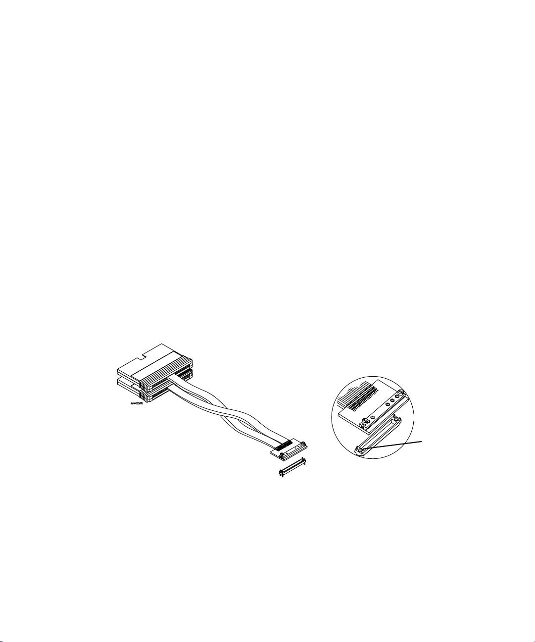
E5386A Half-channel Adapter The E5386A can be used with
the E5405A- pro series differential soft touch probe or the
E5402A/E5406A- pro series single- ended probes to map the
signals from the PC board pads to the 16760A when
operating in half- channel state mode.
Figure 47 E5386A Half-channed adapter
68 Soft Touch Pro User’s Guide
Page 69

Agilent E5400-Pro Series Soft Touch Connectorless Probes
User’s Guide
6
Recommended Reading
For More Information 70
A list of recommended reading for more information about
systems and high-speed digital design.
A
69
Page 70

6 Recommended Reading
For More Information
MECL System Design Handbook
For more information on Agilent logic analyzers, refer to
http://www.agilent.com/find/logicanalyzer
information on your specific analyzer, refer to the online
help in the product.
For information on other Agilent probing solutions, refer to
http://www.agilent.com/find/logic_analyzer_probes.
Blood, William R. Jr., "MECL System Design Handbook," 4th
edition, 1988, published by Motorola. This handbook can be
obtained from ON Semiconductor on the web. Go to
<http://onsemi.com>. Click on "On-line ordering" under
"Documentation." Click on the link "General search." Type in
"HB205" in the "Document number" field. Click "Submit." To
view the document online, click on "PDF" in the right- hand
column titled "PDF MFAX." Or order a hardcopy of the
handbook on- line.
. For more
High-speed Digital Design
Johnson, Howard W., and Martin Graham, "High- speed
Digital Design," Prentice- Hall, 1993, ISBN 0- 13- 395724- 1
Designing High-speed Target Systems for Logic Analyzer Probing
“Designing High- speed Target Systems for Logic Analyzer
Probing” Agilent Technologies application note publication
number 5988- 2989EN.
70 E5400-Pro Series Soft Touch User’s Guide
Page 71

Safety Notices
This apparatus has been designed and tested in accordance with IEC Publication 1010,
Safety Requirements for Measuring Apparatus, and has been supplied in a safe condition. This is a Safety Class I instrument (provided with terminal for protective earthing).
Before applying power, verify that the correct safety precautions are taken (see the following warnings). In addition, note the external markings on the instrument that are
described under "Safety Symbols."
Warnings
• Before turning on the instrument, you must connect the protective earth terminal of the
instrument to the protective conductor of the (mains) power cord. The mains plug shall
only be inserted in a socket outlet provided with a protective earth contact. You must not
negate the protective action by using an extension cord (power cable) without a protective conductor (grounding). Grounding one conductor of a two-conductor outlet is not sufficient protection.
• Only fuses with the required rated current, voltage, and specified type (normal blow,
time delay, etc.) should be used. Do not use repaired fuses or short-circuited fuseholders.
To do so could cause a shock or fire hazard.
• If you energize this instrument by an auto transformer (for voltage reduction or mains
isolation), the common terminal must be connected to the earth terminal of the power
source.
• Whenever it is likely that the ground protection is impaired, you must make the instru-
ment inoperative and secure it against any unintended operation.
• Service instructions are for trained service personnel. To avoid dangerous electric
shock, do not perform any service unless qualified to do so. Do not attempt internal service or adjustment unless another person, capable of rendering first aid and resuscitation, is present.
• Do not install substitute parts or perform any unauthorized modification to the instru-
ment.
• Capacitors inside the instrument may retain a charge even if the instrument is discon-
nected from its source of supply.
• Do not operate the instrument in the presence of flammable gasses or fumes. Operation
of any electrical instrument in such an environment constitutes a definite safety hazard.
• Do not use the instrument in a manner not specified by the manufacturer.
To clean the instrument
If the instrument requires cleaning: (1) Remove power from the instrument. (2) Clean the
external surfaces of the instrument with a soft cloth dampened with a mixture of mild
detergent and water. (3) Make sure that the instrument is completely dry before reconnecting it to a power source.
E5400-Pro Series Soft Touch User’s Guide 71
Page 72

Safety Symbols
!
Instruction manual symbol: the product is marked with this symbol when it is necessary
for you to refer to the instruction manual in order to protect against damage to the product..
Hazardous voltage symbol.
Earth terminal symbol: Used to indicate a circuit common connected to grounded chassis.
72 E5400-Pro Series Soft Touch User’s Guide
Page 73

Index
A
adapter, E5386A half-channel, 18
Agilent web site
logic analyzer info, 70
probing, 70
soft touch probes, 13
amplitude, 16
analyzer, 70
at a glance, 8
attach retention module, 10
B
bottom-side attach, 11
C
Characteristics, 20
circuit board design, 59
cleaning the instrument, 71
clock inputs, 63
E5405A, 66
E5406A, 67
D
data inputs, 63
E5404A, 66
E5405A, 66
E5406A, 67
definition
differential input, 16
design
for logic analyzer probing, 70
high-speed digital, 70
high-speed target systems, 70
MECL, 70
design theory, 59
differential
input amplitude, 16
differential probe
E5405A, 16
dimensions
E5386A half-channel adapter, 36
E5404A probe, 21
E5405A probe, 23
E5406A probe, 24
footprint, 27
retention module, 25
E
E5386A half-channel adapter, 18
E5404A 34-chan single ended, 14, 15
E5405A 17-chan differential, 16
E5406A 34-chan single-ended, 17
equivalent probe loads
E5404A, 42
E5405A, 48
E5406A, 48
eye opening, 56
eye scan, 63
F
footprint dimensions, 27
H
half-channel adapter, 18
half-channel mode, 68
high-speed
digital design, 70
target system design, 70
I
input amplitude, 16
installation, 10
instrument, cleaning the, 71
K
keep-out area, 27
keying pin, 11
L
labels, 67
logic analyzer, 70
design for probing, 70
M
MECL system design, 70
N
Notices, 71
number of probes required, 12
O
operating mode, 63
ordering retention modules, 13
overview, 8
P
pinout, 28
E5386A used with E5387A, 37
E5386A used with E5390A, 38
probe
E5404A single-ended, 14, 15
E5405A 17-chan differential, 16
E5406A 34-chan single-ended, 17
number required, 12
state speed, 13
probe load
E5404A, 42
E5405A, 48
E5406A, 48
probing options, 12
E5400-Pro Series Soft Touch User’s Guide 73
Page 74

Index
R
reordered bits, 67
replaceable part
retention module, 13
required number of probes, 12
retention module
attaching, 10
dimensions, 25
ordering, 13
routing, 61
S
safety symbols, 72
selecting a probe, 12
signal access, 67
single-ended probe
E5405A, 14, 15
E5406A, 17
solder retention module, 11
state speed, 13
step inputs, 53
synchronous state analysis, 63
T
thresholds, 66
time domain transmission, 50
E5404A, 44
top-side attach, 10
transmission line considerations, 60
triggering, 67
74 E5400-Pro Series Soft Touch User’s Guide
 Loading...