

Page 1

<<<<Caution
Caution>>>> The following conditions shall apply for the Visual Basic
CautionCaution
(hereafter “VBA”) equipped in the E4991A RF Impedance/Material Analyzer (hereafter “E4991A”). The
customer shall agree to these conditions before using E4991A.
User
User License Agreement
License Agreement of VBA for
User User
License AgreementLicense Agreement
1. The customer can use VBA only on E4991A and one specified computer.
2. The customer shall use VBA according to the method of use specified by the VBA manual,
accompanying documents, package, display screens, and so on.
3. The company shall not be under any obligation to guarantee that VBA errors will not occur and shall
not be under any obligation to correct VBA errors, even when errors exist. [T.S1]
4. The company, during the E4991A warranty period, shall cover any defect of the software recording
media [T.S2] inside E4991A if it results in the failure to execute VBA programming instructions, even
if VBA is properly installed in E4991A. The company shall not guarantee any other items except for
this item, regardless of indications or revelations, and shall not guarantee conformability towards
VBA products or special objectives. Some countries adopt legislation that does not recognize warranty
of VBA for E4991
of VBA for of VBA for
E4991AAAA
E4991E4991
â
for Applications software
exclusions of indications or revelations. In countries adopting such legislation, the above restriction
shall not apply to the customer. In such cases, the company shall allow the return of E4991A and shall
refund the purchase amount, limited to 30 days from the day VBA is transferred. The customer may
have other rights depending on the country.
5. The company shall not bear any responsibility even if it is announced that there is a possibility of
circumstantial or extraordinary damage (including direct, indirect, or carry-over profits) caused by
VBA. Some countries may adopt legislation that does not recognize the validity of limitations or
exclusions of compensative responsibility for circumstantial damage or consequential damage. In
countries adopting such legislation, the above limitations or exclusions shall not apply. In any case,
however, the company shall not be burdened with compensative responsibility of an amount that
exceeds the amount of money received for E4991A.
Visual Basic
[T.S1] If no customer support service shall be offered, we shall not guarantee that there will be no bugs
or that we will implement corrections, since proposals may be made including training.
[T.S2] We rewrote the term as recording media (i.e., HDD) since it is hard to discriminate between the
Ò
for Applications is a registered trademark of Microsoft Corp. of the U.S.
hard disk and firmware.
[T.S3] We wrote this to show that VBA is a product of Microsoft Corp.
Page 2

Page 3

Caution
Do not exceed the operating input power, voltage, and current
level and signal type appropriate for the instrument being used, refer to
your instrument's Function Reference.
Electrostatic discharge(ESD) can damage the highly sensitive
microcircuits in your instrument. ESD damage is most likely to occur as
the test fixtures are being connected or disconnected. Protect them from
ESD damage by wearing a grounding strap that provides a high
resistance path to ground. Alternatively, ground yourself to discharge any
static charge built-up by touching the outer shell of any grounded
instrument chassis before touching the test port connectors.
E4991A
Page 4

Page 5

Safety Summary
When you notice any of the unusual conditions listed below, immediately
terminate operation and disconnect the power cable.
Contact your local Agilent Technologies sales representative or
authorized service company for repair of the instrument. If you continue
to operate without repairing the instrument, there is a potential fire or
shock hazard for the operator.
n Instrument operates abnormally.
n Instrument emits abnormal noise, smell, smoke or a spark-like light
during the operation.
n Instrument generates high temperature or electrical shock during
operation.
n Power cable, plug, or receptacle on instrument is damaged.
n Foreign substance or liquid has fallen into the instrument.
Page 6

Page 7

Page 8

Page 9

Page 10

Page 11

Agilent E4991A RF Impedance/Material Analyzer
Operation Manual
Fifth Edition
SERIAL NUMBERS
This manual applies directly to instruments that don’t have serial number prefix JP1KH.
For additional information about serial numbers, see Appendix A.
Agilent Part No. E4991-90050
March 2003
Printed in Japan
Page 12

Notices
The information contained in this document is subject to change without notice.
This document contains proprietary information that is protected by copyright. All rights
are reserved. No part of this document may be photocopied, reproduced, or translated to
another language without the prior written consent of Agilent Technologies.
Agilent Technologies Japan, Ltd.
Component Test PGU-Kobe
1-3-2, Murotani, Nishi-ku, Kobe, Hyogo, 651-2241 Japan
© Copyright 2001, 2002, 3003 Agilent Technologies Japan, Ltd.
Manual Printing History
The manual’s printing date and part number indicate its current edition. The printing date
changes when a new edition is printed (minor corrections and updates that are incorporated
at reprint do not cause the date to change). The manual part number changes when
extensive technical changes are incorporated.
March 2001 Preliminary (part number: E4991-90000)
April 2001 First Edition (part number: E4991-90010)
July 2001 Second Edition (part number: E4991-90020)
September 2001 Third Edition (part number: E4991-90030)
February 2002 Fourth Edition (part number: E4991-90040)
March 2003 Fifth Edition (part number: E4991-90050)
2
Page 13

Safety Summary
The following general safety precautions must be observed during all phases of operation,
service, and repair of this instrument. Failure to comply with these precautions or with
specific WARNINGS elsewhere in this manual may impair the protection provided by the
equipment. Such noncompliance would also violate safety standards of design,
manufacture, and intended use of the instrument. Agilent Technologies assumes no liability
for the customer’s failure to comply with these precautions.
NOTE The E4991A complies with INSTALLATION CATEGORY II as well as POLLUTION
DEGREE 2 in IEC61010-1. The E4991A is an INDOOR USE product.
NOTE The LEDs in the E4991A are Class 1 in accordance with IEC60825-1,
CLASS 1 LED PRODUCT
• Ground the Instrument
To avoid electric shock, the instrument chassis and cabinet must be grounded with the
supplied power cable’s grounding prong.
• DO NOT Operate in an Explosive Atmosphere
Do not operate the instrument in the presence of inflammable gasses or fumes.
Operation of any electrical instrument in such an environment clearly constitutes a
safety hazard.
• Keep Away from Live Circuits
Operators must not remove instrument covers. Component replacement and internal
adjustments must be made by qualified maintenance personnel. Do not replace
components with the power cable connected. Under certain conditions, dangerous
voltage levels may remain even after the power cable has been disconnected. To avoid
injuries, always disconnect the power and discharge circuits before touching them.
• DO NOT Service or Adjust the Instrument Alone
Do not attempt internal service or adjustment unless another person, capable of
rendering first aid and resuscitation, is present.
• DO NOT Substitute Parts or Modify the Instrument
To avoid the danger of introducing additional hazards, do not install substitute parts or
perform unauthorized modifications to the instrument. Return the instrument to an
Agilent Technologies Sales and Service Office for service and repair to ensure that
safety features are maintained in operational condition.
• Dangerous Procedure Warnings
Warnings, such as the example below, precede potentially dangerous procedures
throughout this manual. Instructions contained in the warnings must be followed.
WARNING Dangerous voltage levels, capable of causing death, are present in this instrument.
Use extreme caution when handling, testing, and adjusting this instrument.
3
Page 14

Safety Symbols
General definitions of safety symbols used on the instrument or in manuals are listed below.
Instruction Manual symbol: the product is marked with this symbol when it is necessary for
the user to refer to the instrument manual.
Alternating current.
Direct current.
On (Supply).
Off (Supply).
In-position of push-button switch.
Out-position of push-button switch.
A chassis terminal; a connection to the instrument’s chassis, which includes all exposed
metal structure.
Stand-by.
WARNING This warning sign denotes a hazard. It calls attention to a procedure, practice, or
condition that, if not correctly performed or adhered to, could result in injury or
death to personnel.
CAUTION This Caution sign denotes a hazard. It calls attention to a procedure, practice, or condition
that, if not correctly performed or adhered to, could result in damage to or destruction of
part or all of the instrument.
NOTE This Note sign denotes important information. It calls attention to a procedure, practice, or
condition that is essential for the user to understand.
Certification
Agilent Technologies certifies that this product met its published specifications at the time
of shipment from the factory. Agilent Technologies further certifies that its calibration
measurements are traceable to the United States National Institute of Standards and
Technology, to the extent allowed by the Institution’s calibration facility or by the
calibration facilities of other International Standards Organization members.
4
Page 15

Warranty
This Agilent Technologies instrument product is warranted against defects in material and
workmanship for a period of one year from the date of shipment, except that in the case of
certain components listed in this manual, the warranty shall be for the specified period.
During the warranty period, Agilent Technologies will, at its option, either repair or replace
products that prove to be defective.
For warranty service or repair, this product must be returned to a service facility designated
by Agilent Technologies. Buyer shall prepay shipping charges to Agilent Technologies,
and Agilent Technologies shall pay shipping charges to return the product to Buyer.
However, Buyer shall pay all shipping charges, duties, and taxes for products returned to
Agilent Technologies from another country.
Agilent Technologies warrants that its software and firmware designated by Agilent
Technologies for use with an instrument will execute its programming instruction when
properly installed on that instrument. Agilent Technologies does not warrant that the
operation of the instrument, or software, or firmware will be uninterrupted or error free.
Limitation of Warranty
The foregoing warranty shall not apply to defects resulting from improper or inadequate
maintenance by Buyer, Buyer-supplied software or interfacing, unauthorized modification
or misuse, operation outside the environmental specifications for the product, or improper
site preparation or maintenance.
IMPORTANT No other warranty is expressed or implied. Agilent Technologies specifically disclaims the
implied warranties of merchantability and fitness for a particular purpose.
Exclusive Remedies
The remedies provided herein are Buyer’s sole and exclusive remedies. Agilent
Technologies shall not be liable for any direct, indirect, special, incidental, or
consequential damages, whether based on contract, tort, or any other legal theory.
5
Page 16

Assistance
Product maintenance agreements and other customer assistance agreements are available
for Agilent Technologies products.
For any assistance, contact your nearest Agilent Technologies Sales and Service Office.
Addresses are provided at the back of this manual.
Typeface Conventions
Sample (bold) Boldface type is used when a term is defined or
emphasis.
Sample (Italic) Italic type is used for emphasis.
key Indicates a hardkey (key on the front panel or
external keyboard) labeled “Sample.” “key” may
be omitted.
Sample menu/button/box Indicates a menu/button/box on the screen labeled
“Sample” which can be selected/executed by
clicking. “menu,” “button,” or “box” may be
omitted.
Sample block/toolbar Indicates a block (group of hardkeys) or a toolbar
(setup toolbar) labeled “Sample.”
Sample 1 - Sample 2 - Sample 3 Indicates a sequential operation of Sample 1,
Sample 2, and Sample 3 (menu, button, or box).
“-” may be omitted.
6
Page 17

Documentation Map
The following manuals are available for the Agilent E4991A.
• Operational Manual (Part Number E4991-900x0, attached to Option ABA)
This manual describes most of the basic information needed to use the E4991A. It
provides a function overview, detailed operation procedure for each function (from
preparation for measurement to analysis of measurement results), measurement
examples, specifications, and supplemental information. For programming guidance on
performing automatic measurement with the E4991A, please see the Programming
Manual.
• Installation and Quick Start Guide (Part Number E4991-900x1, attached to Option
ABA)
This manual describes installation of the instrument after it is delivered and the basic
procedures for applications and analysis. Refer to this manual when you use the
E4991A for the first time.
• Programming Manual (Part Number E4991-900x2, attached to Option ABA)
This manual provides programming information for performing automatic
measurement with the E4991A. It includes an outline of remote control, procedures for
detecting measurement start (trigger) and end (sweep end), application programming
examples, a command reference, and related information.
NOTE The number position shown by “x” in the part numbers above indicates the edition number.
This convention is applied to each manual, CD-ROM (for manuals), and sample programs
disk issued. Here, “0” indicates the initial edition, and each time a revision is made this
number is incremented by 1. The latest edition allows the customer to specify Option ABJ
(Japanese) or Option ABA (English) of the product.
MicrosoftÒ, MS-DOSÒ, WindowsÒ, and Visual BasicÒ for Applications are registered
trademarks of Microsoft Corporation in U.S. and other countries.
7
Page 18

8
Page 19

1. How to Use This Operation Manual
Relationship of Operation Manual Contents to Using the E4991A . . . . . . . . . . . . . . . . . . . . . . . . . . . . . . . 20
2. Function Overview
Names and Functions of Front Panel Blocks . . . . . . . . . . . . . . . . . . . . . . . . . . . . . . . . . . . . . . . . . . . . . . . . 22
1. Standby switch . . . . . . . . . . . . . . . . . . . . . . . . . . . . . . . . . . . . . . . . . . . . . . . . . . . . . . . . . . . . . . . . . . . 23
2. 3.5-inch built-in floppy disk drive. . . . . . . . . . . . . . . . . . . . . . . . . . . . . . . . . . . . . . . . . . . . . . . . . . . . . 23
3. Color LCD display . . . . . . . . . . . . . . . . . . . . . . . . . . . . . . . . . . . . . . . . . . . . . . . . . . . . . . . . . . . . . . . . 23
4. Measurement block (MEASUREMENT). . . . . . . . . . . . . . . . . . . . . . . . . . . . . . . . . . . . . . . . . . . . . . . 23
5. Stimulus block (STIMULUS). . . . . . . . . . . . . . . . . . . . . . . . . . . . . . . . . . . . . . . . . . . . . . . . . . . . . . . . 24
6. Entry/navigation block (ENTRY/NAVIGATION) . . . . . . . . . . . . . . . . . . . . . . . . . . . . . . . . . . . . . . . . 25
7. System block (SYSTEM) . . . . . . . . . . . . . . . . . . . . . . . . . . . . . . . . . . . . . . . . . . . . . . . . . . . . . . . . . . . 26
8. Utility key ( key) . . . . . . . . . . . . . . . . . . . . . . . . . . . . . . . . . . . . . . . . . . . . . . . . . . . . . . . . . . . . . . . . . . 26
9. Test head interface (TEST HEAD INTERFACE). . . . . . . . . . . . . . . . . . . . . . . . . . . . . . . . . . . . . . . . . 26
Names and Functions of Rear Panel Blocks. . . . . . . . . . . . . . . . . . . . . . . . . . . . . . . . . . . . . . . . . . . . . . . . . 28
1. Power cable receptacle (-LINE) . . . . . . . . . . . . . . . . . . . . . . . . . . . . . . . . . . . . . . . . . . . . . . . . . . . . . . 29
2. Unused ports (Reserved). . . . . . . . . . . . . . . . . . . . . . . . . . . . . . . . . . . . . . . . . . . . . . . . . . . . . . . . . . . . 29
3. External trigger input connector (Ext Trig). . . . . . . . . . . . . . . . . . . . . . . . . . . . . . . . . . . . . . . . . . . . . . 29
4. External monitor output terminal (VIDEO) . . . . . . . . . . . . . . . . . . . . . . . . . . . . . . . . . . . . . . . . . . . . . 29
5. LAN port . . . . . . . . . . . . . . . . . . . . . . . . . . . . . . . . . . . . . . . . . . . . . . . . . . . . . . . . . . . . . . . . . . . . . . . . 29
6. GPIB connector. . . . . . . . . . . . . . . . . . . . . . . . . . . . . . . . . . . . . . . . . . . . . . . . . . . . . . . . . . . . . . . . . . . 29
7. High stability frequency reference output connector (Ref Oven, Option 1D5 only) . . . . . . . . . . . . . . 29
8. External reference signal input terminal (Ext Ref In, 10 MHz 0 dBm) . . . . . . . . . . . . . . . . . . . . . . . . 30
9. Internal reference signal output connector (Int Ref Out) . . . . . . . . . . . . . . . . . . . . . . . . . . . . . . . . . . . 30
10. Printer parallel port (PRINTER, Parallel). . . . . . . . . . . . . . . . . . . . . . . . . . . . . . . . . . . . . . . . . . . . . . 30
11. Mini-DIN mouse port (MOUSE) . . . . . . . . . . . . . . . . . . . . . . . . . . . . . . . . . . . . . . . . . . . . . . . . . . . . 30
12. Mini-Din keyboard port (KYBD) . . . . . . . . . . . . . . . . . . . . . . . . . . . . . . . . . . . . . . . . . . . . . . . . . . . . 30
13. Serial number plate . . . . . . . . . . . . . . . . . . . . . . . . . . . . . . . . . . . . . . . . . . . . . . . . . . . . . . . . . . . . . . . 31
14. Unused ports (Reserved). . . . . . . . . . . . . . . . . . . . . . . . . . . . . . . . . . . . . . . . . . . . . . . . . . . . . . . . . . . 31
Names and Functions of LCD Display Areas. . . . . . . . . . . . . . . . . . . . . . . . . . . . . . . . . . . . . . . . . . . . . . . . 32
1. Title bar . . . . . . . . . . . . . . . . . . . . . . . . . . . . . . . . . . . . . . . . . . . . . . . . . . . . . . . . . . . . . . . . . . . . . . . . . 32
2. Menu bar . . . . . . . . . . . . . . . . . . . . . . . . . . . . . . . . . . . . . . . . . . . . . . . . . . . . . . . . . . . . . . . . . . . . . . . . 32
3. Marker values . . . . . . . . . . . . . . . . . . . . . . . . . . . . . . . . . . . . . . . . . . . . . . . . . . . . . . . . . . . . . . . . . . . . 34
4. Setup toolbar . . . . . . . . . . . . . . . . . . . . . . . . . . . . . . . . . . . . . . . . . . . . . . . . . . . . . . . . . . . . . . . . . . . . . 35
5. Trace 1. . . . . . . . . . . . . . . . . . . . . . . . . . . . . . . . . . . . . . . . . . . . . . . . . . . . . . . . . . . . . . . . . . . . . . . . . . 38
6. Trace 2. . . . . . . . . . . . . . . . . . . . . . . . . . . . . . . . . . . . . . . . . . . . . . . . . . . . . . . . . . . . . . . . . . . . . . . . . . 38
7. Markers . . . . . . . . . . . . . . . . . . . . . . . . . . . . . . . . . . . . . . . . . . . . . . . . . . . . . . . . . . . . . . . . . . . . . . . . . 38
8. Scale reference line value . . . . . . . . . . . . . . . . . . . . . . . . . . . . . . . . . . . . . . . . . . . . . . . . . . . . . . . . . . . 38
9. Trace 1 axis . . . . . . . . . . . . . . . . . . . . . . . . . . . . . . . . . . . . . . . . . . . . . . . . . . . . . . . . . . . . . . . . . . . . . . 38
10. Sweep start value. . . . . . . . . . . . . . . . . . . . . . . . . . . . . . . . . . . . . . . . . . . . . . . . . . . . . . . . . . . . . . . . . 38
11. Sweep stop value. . . . . . . . . . . . . . . . . . . . . . . . . . . . . . . . . . . . . . . . . . . . . . . . . . . . . . . . . . . . . . . . . 38
12. Trace 2 axis . . . . . . . . . . . . . . . . . . . . . . . . . . . . . . . . . . . . . . . . . . . . . . . . . . . . . . . . . . . . . . . . . . . . . 38
13. Status bar. . . . . . . . . . . . . . . . . . . . . . . . . . . . . . . . . . . . . . . . . . . . . . . . . . . . . . . . . . . . . . . . . . . . . . . 39
Contents
3. Setting Measurement Conditions
Initialization of E4991A (presetting) . . . . . . . . . . . . . . . . . . . . . . . . . . . . . . . . . . . . . . . . . . . . . . . . . . . . . . 42
Setting Material Measurement Parameter (Option 002 only). . . . . . . . . . . . . . . . . . . . . . . . . . . . . . . . . . . . 43
Procedure. . . . . . . . . . . . . . . . . . . . . . . . . . . . . . . . . . . . . . . . . . . . . . . . . . . . . . . . . . . . . . . . . . . . . . . . . . 43
9
Page 20

Contents
Selection and Confirmation of Target Trace (Active Trace) . . . . . . . . . . . . . . . . . . . . . . . . . . . . . . . . . . . . 45
Selecting Active Trace . . . . . . . . . . . . . . . . . . . . . . . . . . . . . . . . . . . . . . . . . . . . . . . . . . . . . . . . . . . . . . . 45
Identifying Active Trace. . . . . . . . . . . . . . . . . . . . . . . . . . . . . . . . . . . . . . . . . . . . . . . . . . . . . . . . . . . . . . 45
Selecting Sweep Parameter . . . . . . . . . . . . . . . . . . . . . . . . . . . . . . . . . . . . . . . . . . . . . . . . . . . . . . . . . . . . . 46
Procedure . . . . . . . . . . . . . . . . . . . . . . . . . . . . . . . . . . . . . . . . . . . . . . . . . . . . . . . . . . . . . . . . . . . . . . . . . 46
Using Time as Sweep Parameter (Zero Span Sweep) . . . . . . . . . . . . . . . . . . . . . . . . . . . . . . . . . . . . . . . . . 47
Procedure . . . . . . . . . . . . . . . . . . . . . . . . . . . . . . . . . . . . . . . . . . . . . . . . . . . . . . . . . . . . . . . . . . . . . . . . . 47
Selecting Sweep Type (Linear/Log/Segment) . . . . . . . . . . . . . . . . . . . . . . . . . . . . . . . . . . . . . . . . . . . . . . . 48
Procedure . . . . . . . . . . . . . . . . . . . . . . . . . . . . . . . . . . . . . . . . . . . . . . . . . . . . . . . . . . . . . . . . . . . . . . . . . 48
Selecting Sweep Direction . . . . . . . . . . . . . . . . . . . . . . . . . . . . . . . . . . . . . . . . . . . . . . . . . . . . . . . . . . . . . . 49
Procedure . . . . . . . . . . . . . . . . . . . . . . . . . . . . . . . . . . . . . . . . . . . . . . . . . . . . . . . . . . . . . . . . . . . . . . . . . 49
Measurement Waiting Time/Sweep Time Setting . . . . . . . . . . . . . . . . . . . . . . . . . . . . . . . . . . . . . . . . . . . . 50
Procedure . . . . . . . . . . . . . . . . . . . . . . . . . . . . . . . . . . . . . . . . . . . . . . . . . . . . . . . . . . . . . . . . . . . . . . . . . 51
Setting Sweep Range . . . . . . . . . . . . . . . . . . . . . . . . . . . . . . . . . . . . . . . . . . . . . . . . . . . . . . . . . . . . . . . . . . 52
Procedure . . . . . . . . . . . . . . . . . . . . . . . . . . . . . . . . . . . . . . . . . . . . . . . . . . . . . . . . . . . . . . . . . . . . . . . . . 52
Setting Sweep Area with Marker . . . . . . . . . . . . . . . . . . . . . . . . . . . . . . . . . . . . . . . . . . . . . . . . . . . . . . . . . 54
Procedure . . . . . . . . . . . . . . . . . . . . . . . . . . . . . . . . . . . . . . . . . . . . . . . . . . . . . . . . . . . . . . . . . . . . . . . . . 56
Setting Number of Points (NOP) . . . . . . . . . . . . . . . . . . . . . . . . . . . . . . . . . . . . . . . . . . . . . . . . . . . . . . . . . 57
Procedure . . . . . . . . . . . . . . . . . . . . . . . . . . . . . . . . . . . . . . . . . . . . . . . . . . . . . . . . . . . . . . . . . . . . . . . . . 57
Oscillator Level Setting . . . . . . . . . . . . . . . . . . . . . . . . . . . . . . . . . . . . . . . . . . . . . . . . . . . . . . . . . . . . . . . . 58
Definition of Oscillator Level Setting . . . . . . . . . . . . . . . . . . . . . . . . . . . . . . . . . . . . . . . . . . . . . . . . . . . 58
Procedure . . . . . . . . . . . . . . . . . . . . . . . . . . . . . . . . . . . . . . . . . . . . . . . . . . . . . . . . . . . . . . . . . . . . . . . . . 59
Setting and Applying dc Bias. . . . . . . . . . . . . . . . . . . . . . . . . . . . . . . . . . . . . . . . . . . . . . . . . . . . . . . . . . . . 60
Procedure . . . . . . . . . . . . . . . . . . . . . . . . . . . . . . . . . . . . . . . . . . . . . . . . . . . . . . . . . . . . . . . . . . . . . . . . . 60
Setting the Trigger Source To Start Sweep. . . . . . . . . . . . . . . . . . . . . . . . . . . . . . . . . . . . . . . . . . . . . . . . . . 61
Procedure . . . . . . . . . . . . . . . . . . . . . . . . . . . . . . . . . . . . . . . . . . . . . . . . . . . . . . . . . . . . . . . . . . . . . . . . . 61
Selecting Trigger Target (Trigger Event) . . . . . . . . . . . . . . . . . . . . . . . . . . . . . . . . . . . . . . . . . . . . . . . . . . . 62
Procedure . . . . . . . . . . . . . . . . . . . . . . . . . . . . . . . . . . . . . . . . . . . . . . . . . . . . . . . . . . . . . . . . . . . . . . . . . 62
Single Sweep, Continuous Sweep and Sweep Stop . . . . . . . . . . . . . . . . . . . . . . . . . . . . . . . . . . . . . . . . . . . 63
Procedure . . . . . . . . . . . . . . . . . . . . . . . . . . . . . . . . . . . . . . . . . . . . . . . . . . . . . . . . . . . . . . . . . . . . . . . . . 63
Selecting Polarity of External Trigger Input Signal . . . . . . . . . . . . . . . . . . . . . . . . . . . . . . . . . . . . . . . . . . . 64
Procedure . . . . . . . . . . . . . . . . . . . . . . . . . . . . . . . . . . . . . . . . . . . . . . . . . . . . . . . . . . . . . . . . . . . . . . . . . 64
CW Frequency Setting . . . . . . . . . . . . . . . . . . . . . . . . . . . . . . . . . . . . . . . . . . . . . . . . . . . . . . . . . . . . . . . . . 65
Procedure . . . . . . . . . . . . . . . . . . . . . . . . . . . . . . . . . . . . . . . . . . . . . . . . . . . . . . . . . . . . . . . . . . . . . . . . . 65
Sweeping a Plural Number of Sweep Areas under Different Conditions at One Time (Segment Sweep) . 66
Procedure . . . . . . . . . . . . . . . . . . . . . . . . . . . . . . . . . . . . . . . . . . . . . . . . . . . . . . . . . . . . . . . . . . . . . . . . . 67
Averaging Measurement Results . . . . . . . . . . . . . . . . . . . . . . . . . . . . . . . . . . . . . . . . . . . . . . . . . . . . . . . . . 71
Averaging Plural Sweeps (Sweep-to-Sweep Averaging) . . . . . . . . . . . . . . . . . . . . . . . . . . . . . . . . . . . . . 71
Averaging by Each Measurement Point (Point Averaging) . . . . . . . . . . . . . . . . . . . . . . . . . . . . . . . . . . . 73
4. Calibration and Compensation
Outline of Calibration and Compensation Functions. . . . . . . . . . . . . . . . . . . . . . . . . . . . . . . . . . . . . . . . . . 76
Types of Calibration and Compensation. . . . . . . . . . . . . . . . . . . . . . . . . . . . . . . . . . . . . . . . . . . . . . . . . . 76
Calibration Reference Plane and Calibration Standard . . . . . . . . . . . . . . . . . . . . . . . . . . . . . . . . . . . . . . 77
Calibration/Compensation measurement point mode. . . . . . . . . . . . . . . . . . . . . . . . . . . . . . . . . . . . . . . . 78
Calibration and Compensation Using 7-mm Test Port as a Calibration Reference Plane . . . . . . . . . . . . . . 81
Calibration using DUT Connecting Terminal as a Calibration Reference Plane . . . . . . . . . . . . . . . . . . . . . 83
Calibration of Open/Short/Load/Low-loss Capacitor . . . . . . . . . . . . . . . . . . . . . . . . . . . . . . . . . . . . . . . . . 84
Port Extension Compensation . . . . . . . . . . . . . . . . . . . . . . . . . . . . . . . . . . . . . . . . . . . . . . . . . . . . . . . . . . . 86
10
Page 21

Procedure. . . . . . . . . . . . . . . . . . . . . . . . . . . . . . . . . . . . . . . . . . . . . . . . . . . . . . . . . . . . . . . . . . . . . . . . . . 86
Electrical Length Compensation. . . . . . . . . . . . . . . . . . . . . . . . . . . . . . . . . . . . . . . . . . . . . . . . . . . . . . . . . . 87
Procedure. . . . . . . . . . . . . . . . . . . . . . . . . . . . . . . . . . . . . . . . . . . . . . . . . . . . . . . . . . . . . . . . . . . . . . . . . . 88
Fixture Compensation. . . . . . . . . . . . . . . . . . . . . . . . . . . . . . . . . . . . . . . . . . . . . . . . . . . . . . . . . . . . . . . . . . 89
Measuring Fixture Compensation Data. . . . . . . . . . . . . . . . . . . . . . . . . . . . . . . . . . . . . . . . . . . . . . . . . . . 89
Switching Fixture Compensation On/Off . . . . . . . . . . . . . . . . . . . . . . . . . . . . . . . . . . . . . . . . . . . . . . . . . 90
Definition of Calibration/Compensation Kit . . . . . . . . . . . . . . . . . . . . . . . . . . . . . . . . . . . . . . . . . . . . . . . . 91
Definition of Calibration Kit. . . . . . . . . . . . . . . . . . . . . . . . . . . . . . . . . . . . . . . . . . . . . . . . . . . . . . . . . . . 91
Definition of Calibration Kit in Permittivity Measurement . . . . . . . . . . . . . . . . . . . . . . . . . . . . . . . . . . . 92
Definition of Compensation Kit . . . . . . . . . . . . . . . . . . . . . . . . . . . . . . . . . . . . . . . . . . . . . . . . . . . . . . . . 92
Restoring Calibration/Compensation Status . . . . . . . . . . . . . . . . . . . . . . . . . . . . . . . . . . . . . . . . . . . . . . . . . 94
Procedure. . . . . . . . . . . . . . . . . . . . . . . . . . . . . . . . . . . . . . . . . . . . . . . . . . . . . . . . . . . . . . . . . . . . . . . . . . 94
5. Display Setting
Setting the Types and Numbers of Display Traces. . . . . . . . . . . . . . . . . . . . . . . . . . . . . . . . . . . . . . . . . . . . 96
Procedure. . . . . . . . . . . . . . . . . . . . . . . . . . . . . . . . . . . . . . . . . . . . . . . . . . . . . . . . . . . . . . . . . . . . . . . . . . 96
Maximize a Display Window on the Screen. . . . . . . . . . . . . . . . . . . . . . . . . . . . . . . . . . . . . . . . . . . . . . . . . 98
Procedure. . . . . . . . . . . . . . . . . . . . . . . . . . . . . . . . . . . . . . . . . . . . . . . . . . . . . . . . . . . . . . . . . . . . . . . . . . 99
Selecting Measurement Parameter (Impedance Measurement) . . . . . . . . . . . . . . . . . . . . . . . . . . . . . . . . . 100
Procedure. . . . . . . . . . . . . . . . . . . . . . . . . . . . . . . . . . . . . . . . . . . . . . . . . . . . . . . . . . . . . . . . . . . . . . . . . 101
Setting Measurement Parameter (Material Measurement). . . . . . . . . . . . . . . . . . . . . . . . . . . . . . . . . . . . . 102
Procedure. . . . . . . . . . . . . . . . . . . . . . . . . . . . . . . . . . . . . . . . . . . . . . . . . . . . . . . . . . . . . . . . . . . . . . . . . 102
Selecting Graph Coordinate Format . . . . . . . . . . . . . . . . . . . . . . . . . . . . . . . . . . . . . . . . . . . . . . . . . . . . . . 104
Procedure. . . . . . . . . . . . . . . . . . . . . . . . . . . . . . . . . . . . . . . . . . . . . . . . . . . . . . . . . . . . . . . . . . . . . . . . . 105
Autoscale Adjustment. . . . . . . . . . . . . . . . . . . . . . . . . . . . . . . . . . . . . . . . . . . . . . . . . . . . . . . . . . . . . . . . . 107
Autoscale Adjustment for each Trace . . . . . . . . . . . . . . . . . . . . . . . . . . . . . . . . . . . . . . . . . . . . . . . . . . . 107
Autoscale Adjustment for all Traces at Once . . . . . . . . . . . . . . . . . . . . . . . . . . . . . . . . . . . . . . . . . . . . . 107
Manual Scale Setting . . . . . . . . . . . . . . . . . . . . . . . . . . . . . . . . . . . . . . . . . . . . . . . . . . . . . . . . . . . . . . . . . 108
Scale Setting in Rectangular Coordinates. . . . . . . . . . . . . . . . . . . . . . . . . . . . . . . . . . . . . . . . . . . . . . . . 108
Scale Setting on Complex Plane . . . . . . . . . . . . . . . . . . . . . . . . . . . . . . . . . . . . . . . . . . . . . . . . . . . . . . . 111
Scale Setting in Polar Coordinate Format. . . . . . . . . . . . . . . . . . . . . . . . . . . . . . . . . . . . . . . . . . . . . . . . 112
Setting of Reference Line Value by Using Marker . . . . . . . . . . . . . . . . . . . . . . . . . . . . . . . . . . . . . . . . . 112
Zooming a Trace. . . . . . . . . . . . . . . . . . . . . . . . . . . . . . . . . . . . . . . . . . . . . . . . . . . . . . . . . . . . . . . . . . . . . 113
Procedure. . . . . . . . . . . . . . . . . . . . . . . . . . . . . . . . . . . . . . . . . . . . . . . . . . . . . . . . . . . . . . . . . . . . . . . . . 113
Overlay Display and Split Display of Graphs . . . . . . . . . . . . . . . . . . . . . . . . . . . . . . . . . . . . . . . . . . . . . . 114
Procedure. . . . . . . . . . . . . . . . . . . . . . . . . . . . . . . . . . . . . . . . . . . . . . . . . . . . . . . . . . . . . . . . . . . . . . . . . 114
Displaying Measurement Values in List Form . . . . . . . . . . . . . . . . . . . . . . . . . . . . . . . . . . . . . . . . . . . . . . 115
Procedure. . . . . . . . . . . . . . . . . . . . . . . . . . . . . . . . . . . . . . . . . . . . . . . . . . . . . . . . . . . . . . . . . . . . . . . . . 115
Trace Comparison Using Memory Trace . . . . . . . . . . . . . . . . . . . . . . . . . . . . . . . . . . . . . . . . . . . . . . . . . . 116
Comparison with a stored reference trace. . . . . . . . . . . . . . . . . . . . . . . . . . . . . . . . . . . . . . . . . . . . . . . . 116
Subtraction of Offset Value . . . . . . . . . . . . . . . . . . . . . . . . . . . . . . . . . . . . . . . . . . . . . . . . . . . . . . . . . . . 116
Offset Value Setting by Using the Marker . . . . . . . . . . . . . . . . . . . . . . . . . . . . . . . . . . . . . . . . . . . . . . . 117
Selecting Sweep Area Display (Start/Stop or Center/Span) . . . . . . . . . . . . . . . . . . . . . . . . . . . . . . . . . . . . 118
Procedure. . . . . . . . . . . . . . . . . . . . . . . . . . . . . . . . . . . . . . . . . . . . . . . . . . . . . . . . . . . . . . . . . . . . . . . . . 118
Setting Frequency Display Resolution . . . . . . . . . . . . . . . . . . . . . . . . . . . . . . . . . . . . . . . . . . . . . . . . . . . . 119
Procedure. . . . . . . . . . . . . . . . . . . . . . . . . . . . . . . . . . . . . . . . . . . . . . . . . . . . . . . . . . . . . . . . . . . . . . . . . 119
Confirm the Setting Status on the Screen. . . . . . . . . . . . . . . . . . . . . . . . . . . . . . . . . . . . . . . . . . . . . . . . . . 120
Procedure. . . . . . . . . . . . . . . . . . . . . . . . . . . . . . . . . . . . . . . . . . . . . . . . . . . . . . . . . . . . . . . . . . . . . . . . . 121
Continuous Phase Display Without Returning at ±180°. . . . . . . . . . . . . . . . . . . . . . . . . . . . . . . . . . . . . . . 122
Contents
11
Page 22

Contents
Procedure . . . . . . . . . . . . . . . . . . . . . . . . . . . . . . . . . . . . . . . . . . . . . . . . . . . . . . . . . . . . . . . . . . . . . . . . 122
Selecting Phase Unit. . . . . . . . . . . . . . . . . . . . . . . . . . . . . . . . . . . . . . . . . . . . . . . . . . . . . . . . . . . . . . . . . . 123
Procedure . . . . . . . . . . . . . . . . . . . . . . . . . . . . . . . . . . . . . . . . . . . . . . . . . . . . . . . . . . . . . . . . . . . . . . . . 123
Displaying Trace Title on Measurement Display. . . . . . . . . . . . . . . . . . . . . . . . . . . . . . . . . . . . . . . . . . . . 124
Procedure . . . . . . . . . . . . . . . . . . . . . . . . . . . . . . . . . . . . . . . . . . . . . . . . . . . . . . . . . . . . . . . . . . . . . . . . 124
Changing Display Colors . . . . . . . . . . . . . . . . . . . . . . . . . . . . . . . . . . . . . . . . . . . . . . . . . . . . . . . . . . . . . . 126
Procedure . . . . . . . . . . . . . . . . . . . . . . . . . . . . . . . . . . . . . . . . . . . . . . . . . . . . . . . . . . . . . . . . . . . . . . . . 126
6. Analysis of Measurement Results
Reading Value on the Trace by Specifying Stimulus Value . . . . . . . . . . . . . . . . . . . . . . . . . . . . . . . . . . . . 128
Procedure . . . . . . . . . . . . . . . . . . . . . . . . . . . . . . . . . . . . . . . . . . . . . . . . . . . . . . . . . . . . . . . . . . . . . . . . 129
Displaying the Values of Plural Points on a Trace in a Value List . . . . . . . . . . . . . . . . . . . . . . . . . . . . . . . 130
Procedure . . . . . . . . . . . . . . . . . . . . . . . . . . . . . . . . . . . . . . . . . . . . . . . . . . . . . . . . . . . . . . . . . . . . . . . . 130
Reading Difference from Reference Point on a Graph (Delta Marker) . . . . . . . . . . . . . . . . . . . . . . . . . . . 131
Delta Marker Function . . . . . . . . . . . . . . . . . . . . . . . . . . . . . . . . . . . . . . . . . . . . . . . . . . . . . . . . . . . . . . 131
Procedure . . . . . . . . . . . . . . . . . . . . . . . . . . . . . . . . . . . . . . . . . . . . . . . . . . . . . . . . . . . . . . . . . . . . . . . . 133
Reading Only the Actual Measurement Point/Reading the Distance between Measurement Points through
Interpolation . . . . . . . . . . . . . . . . . . . . . . . . . . . . . . . . . . . . . . . . . . . . . . . . . . . . . . . . . . . . . . . . . . . . . . . . 135
Procedure . . . . . . . . . . . . . . . . . . . . . . . . . . . . . . . . . . . . . . . . . . . . . . . . . . . . . . . . . . . . . . . . . . . . . . . . 135
Move the Marker for Each Trace Independently . . . . . . . . . . . . . . . . . . . . . . . . . . . . . . . . . . . . . . . . . . . . 136
Selecting Marker Value Display for Plural Parameters . . . . . . . . . . . . . . . . . . . . . . . . . . . . . . . . . . . . . . . 137
Procedure . . . . . . . . . . . . . . . . . . . . . . . . . . . . . . . . . . . . . . . . . . . . . . . . . . . . . . . . . . . . . . . . . . . . . . . . 138
Selecting Marker Analysis Target Trace (Data/Memory) . . . . . . . . . . . . . . . . . . . . . . . . . . . . . . . . . . . . . 139
Procedure . . . . . . . . . . . . . . . . . . . . . . . . . . . . . . . . . . . . . . . . . . . . . . . . . . . . . . . . . . . . . . . . . . . . . . . . 139
Search for Max. and Min. Measurement Value . . . . . . . . . . . . . . . . . . . . . . . . . . . . . . . . . . . . . . . . . . . . . 140
Procedure . . . . . . . . . . . . . . . . . . . . . . . . . . . . . . . . . . . . . . . . . . . . . . . . . . . . . . . . . . . . . . . . . . . . . . . . 140
Search for Target Point of Measurement Value . . . . . . . . . . . . . . . . . . . . . . . . . . . . . . . . . . . . . . . . . . . . . 142
Procedure . . . . . . . . . . . . . . . . . . . . . . . . . . . . . . . . . . . . . . . . . . . . . . . . . . . . . . . . . . . . . . . . . . . . . . . . 142
Peak Search . . . . . . . . . . . . . . . . . . . . . . . . . . . . . . . . . . . . . . . . . . . . . . . . . . . . . . . . . . . . . . . . . . . . . . . . 144
Maximal Point and Minimal Point . . . . . . . . . . . . . . . . . . . . . . . . . . . . . . . . . . . . . . . . . . . . . . . . . . . . . 144
Positive Peak and Negative Peak . . . . . . . . . . . . . . . . . . . . . . . . . . . . . . . . . . . . . . . . . . . . . . . . . . . . . . 145
Outline of Peak Search Function . . . . . . . . . . . . . . . . . . . . . . . . . . . . . . . . . . . . . . . . . . . . . . . . . . . . . . 146
Procedure . . . . . . . . . . . . . . . . . . . . . . . . . . . . . . . . . . . . . . . . . . . . . . . . . . . . . . . . . . . . . . . . . . . . . . . . 146
Define the Peaks Using Marker . . . . . . . . . . . . . . . . . . . . . . . . . . . . . . . . . . . . . . . . . . . . . . . . . . . . . . . 148
Working Out Trace Average, Standard Deviation, and Peak to Peak. . . . . . . . . . . . . . . . . . . . . . . . . . . . . 151
Procedure . . . . . . . . . . . . . . . . . . . . . . . . . . . . . . . . . . . . . . . . . . . . . . . . . . . . . . . . . . . . . . . . . . . . . . . . 151
Specify the Partial Search Area . . . . . . . . . . . . . . . . . . . . . . . . . . . . . . . . . . . . . . . . . . . . . . . . . . . . . . . . . 153
Procedure . . . . . . . . . . . . . . . . . . . . . . . . . . . . . . . . . . . . . . . . . . . . . . . . . . . . . . . . . . . . . . . . . . . . . . . . 153
Execution of Automatic Search in Each Sweep (Search Tracking) . . . . . . . . . . . . . . . . . . . . . . . . . . . . . . 155
Procedure . . . . . . . . . . . . . . . . . . . . . . . . . . . . . . . . . . . . . . . . . . . . . . . . . . . . . . . . . . . . . . . . . . . . . . . . 155
Changing Marker Stimulus Value Display to Time/Relaxation Time . . . . . . . . . . . . . . . . . . . . . . . . . . . . 156
Procedure . . . . . . . . . . . . . . . . . . . . . . . . . . . . . . . . . . . . . . . . . . . . . . . . . . . . . . . . . . . . . . . . . . . . . . . . 156
Calculation of Equivalent Circuit Parameter and Simulation of Frequency Characteristics . . . . . . . . . . . 157
Calculation of Equivalent Circuit Parameter based on Measurement Results . . . . . . . . . . . . . . . . . . . . 157
Frequency Characteristics Simulation based on Equivalent Circuit Parameters . . . . . . . . . . . . . . . . . . 158
Setting a Limit to the Trace and Making a Pass/Fail Determination . . . . . . . . . . . . . . . . . . . . . . . . . . . . . 160
Procedure . . . . . . . . . . . . . . . . . . . . . . . . . . . . . . . . . . . . . . . . . . . . . . . . . . . . . . . . . . . . . . . . . . . . . . . . 161
12
Page 23

7. Saving and Recalling Internal Data
Overview of Save and Recall Functions. . . . . . . . . . . . . . . . . . . . . . . . . . . . . . . . . . . . . . . . . . . . . . . . . . . 166
Saving and Recalling Setting States (Save State) . . . . . . . . . . . . . . . . . . . . . . . . . . . . . . . . . . . . . . . . . . . . 169
To save setting states: . . . . . . . . . . . . . . . . . . . . . . . . . . . . . . . . . . . . . . . . . . . . . . . . . . . . . . . . . . . . . . . 169
To recall setting states: . . . . . . . . . . . . . . . . . . . . . . . . . . . . . . . . . . . . . . . . . . . . . . . . . . . . . . . . . . . . . . 170
Saving and Recalling Measurement Data in Binary Format . . . . . . . . . . . . . . . . . . . . . . . . . . . . . . . . . . . 172
To save measurement data in binary format:. . . . . . . . . . . . . . . . . . . . . . . . . . . . . . . . . . . . . . . . . . . . . . 172
To recall measurement data: . . . . . . . . . . . . . . . . . . . . . . . . . . . . . . . . . . . . . . . . . . . . . . . . . . . . . . . . . . 173
Saving Measurement Data to Read in Spreadsheet Software (Saving in ASCII Format) . . . . . . . . . . . . . 175
To save measurement data in ASCII format: . . . . . . . . . . . . . . . . . . . . . . . . . . . . . . . . . . . . . . . . . . . . . 176
To import measurement data saved in ASCII format into Microsoft ExcelÔ:. . . . . . . . . . . . . . . . . . . . 177
Saving Measurement Data in CITIfile Format . . . . . . . . . . . . . . . . . . . . . . . . . . . . . . . . . . . . . . . . . . . . . . 179
Overview of CITIfile Data Format . . . . . . . . . . . . . . . . . . . . . . . . . . . . . . . . . . . . . . . . . . . . . . . . . . . . . 179
How to Create a CITIfile on the E4991A . . . . . . . . . . . . . . . . . . . . . . . . . . . . . . . . . . . . . . . . . . . . . . . . 179
CITIfile Structure . . . . . . . . . . . . . . . . . . . . . . . . . . . . . . . . . . . . . . . . . . . . . . . . . . . . . . . . . . . . . . . . . . 180
To create a CITIfile: . . . . . . . . . . . . . . . . . . . . . . . . . . . . . . . . . . . . . . . . . . . . . . . . . . . . . . . . . . . . . . . . 181
Saving Display Information (Save Graphics). . . . . . . . . . . . . . . . . . . . . . . . . . . . . . . . . . . . . . . . . . . . . . . 183
To save display information:. . . . . . . . . . . . . . . . . . . . . . . . . . . . . . . . . . . . . . . . . . . . . . . . . . . . . . . . . . 183
Recalling Saved Image File. . . . . . . . . . . . . . . . . . . . . . . . . . . . . . . . . . . . . . . . . . . . . . . . . . . . . . . . . . . 184
Contents
8. Printing Measurement Results and Internal Data
Printing Measurement Graphs and Internal Data Lists. . . . . . . . . . . . . . . . . . . . . . . . . . . . . . . . . . . . . . . . 186
Supported Printers. . . . . . . . . . . . . . . . . . . . . . . . . . . . . . . . . . . . . . . . . . . . . . . . . . . . . . . . . . . . . . . . . . 187
How to print data on the screen. . . . . . . . . . . . . . . . . . . . . . . . . . . . . . . . . . . . . . . . . . . . . . . . . . . . . . . . 187
Installing Printer Drivers . . . . . . . . . . . . . . . . . . . . . . . . . . . . . . . . . . . . . . . . . . . . . . . . . . . . . . . . . . . . . . 191
How to install a printer driver: . . . . . . . . . . . . . . . . . . . . . . . . . . . . . . . . . . . . . . . . . . . . . . . . . . . . . . . . 191
9. Setup and Use of Control/Management Functions
Setup and Confirmation of GPIB . . . . . . . . . . . . . . . . . . . . . . . . . . . . . . . . . . . . . . . . . . . . . . . . . . . . . . . . 194
Operation procedure . . . . . . . . . . . . . . . . . . . . . . . . . . . . . . . . . . . . . . . . . . . . . . . . . . . . . . . . . . . . . . . . 194
Setting the Built-in Speaker (beep sound) . . . . . . . . . . . . . . . . . . . . . . . . . . . . . . . . . . . . . . . . . . . . . . . . . 196
Procedure for turning the beeping sound on or off. . . . . . . . . . . . . . . . . . . . . . . . . . . . . . . . . . . . . . . . . 196
Setting the Internal Clock . . . . . . . . . . . . . . . . . . . . . . . . . . . . . . . . . . . . . . . . . . . . . . . . . . . . . . . . . . . . . . 197
Procedure for setting the internal clock. . . . . . . . . . . . . . . . . . . . . . . . . . . . . . . . . . . . . . . . . . . . . . . . . . 197
Setting the Mouse Properties . . . . . . . . . . . . . . . . . . . . . . . . . . . . . . . . . . . . . . . . . . . . . . . . . . . . . . . . . . . 200
Setting procedures. . . . . . . . . . . . . . . . . . . . . . . . . . . . . . . . . . . . . . . . . . . . . . . . . . . . . . . . . . . . . . . . . . 200
Confirmation of Options and Firmware Version . . . . . . . . . . . . . . . . . . . . . . . . . . . . . . . . . . . . . . . . . . . . 203
Operation Procedure . . . . . . . . . . . . . . . . . . . . . . . . . . . . . . . . . . . . . . . . . . . . . . . . . . . . . . . . . . . . . . . . 203
System Recovery . . . . . . . . . . . . . . . . . . . . . . . . . . . . . . . . . . . . . . . . . . . . . . . . . . . . . . . . . . . . . . . . . . . . 204
Notes on executing system recovery . . . . . . . . . . . . . . . . . . . . . . . . . . . . . . . . . . . . . . . . . . . . . . . . . . . 204
Procedure to execute system recovery . . . . . . . . . . . . . . . . . . . . . . . . . . . . . . . . . . . . . . . . . . . . . . . . . . 204
10. Using LAN
LAN Setup . . . . . . . . . . . . . . . . . . . . . . . . . . . . . . . . . . . . . . . . . . . . . . . . . . . . . . . . . . . . . . . . . . . . . . . . . 208
Setup procedure. . . . . . . . . . . . . . . . . . . . . . . . . . . . . . . . . . . . . . . . . . . . . . . . . . . . . . . . . . . . . . . . . . . . 208
File Transfer Using FTP . . . . . . . . . . . . . . . . . . . . . . . . . . . . . . . . . . . . . . . . . . . . . . . . . . . . . . . . . . . . . . . 212
FTP file transfer using MS-DOSÔ prompt. . . . . . . . . . . . . . . . . . . . . . . . . . . . . . . . . . . . . . . . . . . . . . . 212
FTP file transfer using FTP application software . . . . . . . . . . . . . . . . . . . . . . . . . . . . . . . . . . . . . . . . . . 215
13
Page 24

Contents
Stop/Abortion of process/Cut off from server by E4991A operation. . . . . . . . . . . . . . . . . . . . . . . . . . . 216
Using Remote User Interface . . . . . . . . . . . . . . . . . . . . . . . . . . . . . . . . . . . . . . . . . . . . . . . . . . . . . . . . . . . 217
Outline of Remote User Interface. . . . . . . . . . . . . . . . . . . . . . . . . . . . . . . . . . . . . . . . . . . . . . . . . . . . . . 217
Installation of E4991A user interface software . . . . . . . . . . . . . . . . . . . . . . . . . . . . . . . . . . . . . . . . . . . 219
Procedure to uninstall E4991A user interface . . . . . . . . . . . . . . . . . . . . . . . . . . . . . . . . . . . . . . . . . . . . 221
Starting up the E4991A user interface and connecting to the E4991A measurement server. . . . . . . . . 222
Disconnection of E4991A measurement server . . . . . . . . . . . . . . . . . . . . . . . . . . . . . . . . . . . . . . . . . . . 224
Closing the E4991A user interface. . . . . . . . . . . . . . . . . . . . . . . . . . . . . . . . . . . . . . . . . . . . . . . . . . . . . 225
Copying measurement plot and internal data to other application software. . . . . . . . . . . . . . . . . . . . . . 225
11. Specifications and Supplemental Information
Definitions . . . . . . . . . . . . . . . . . . . . . . . . . . . . . . . . . . . . . . . . . . . . . . . . . . . . . . . . . . . . . . . . . . . . . . . . . 228
Measurement Parameters and Range . . . . . . . . . . . . . . . . . . . . . . . . . . . . . . . . . . . . . . . . . . . . . . . . . . . . . 228
Measurement Parameters . . . . . . . . . . . . . . . . . . . . . . . . . . . . . . . . . . . . . . . . . . . . . . . . . . . . . . . . . . . . 228
Measurement Range . . . . . . . . . . . . . . . . . . . . . . . . . . . . . . . . . . . . . . . . . . . . . . . . . . . . . . . . . . . . . . . . 228
Source Characteristics . . . . . . . . . . . . . . . . . . . . . . . . . . . . . . . . . . . . . . . . . . . . . . . . . . . . . . . . . . . . . . . . 229
Frequency . . . . . . . . . . . . . . . . . . . . . . . . . . . . . . . . . . . . . . . . . . . . . . . . . . . . . . . . . . . . . . . . . . . . . . . . 229
Oscillator Level. . . . . . . . . . . . . . . . . . . . . . . . . . . . . . . . . . . . . . . . . . . . . . . . . . . . . . . . . . . . . . . . . . . . 229
Output Impedance. . . . . . . . . . . . . . . . . . . . . . . . . . . . . . . . . . . . . . . . . . . . . . . . . . . . . . . . . . . . . . . . . . 230
DC Bias (Option 001). . . . . . . . . . . . . . . . . . . . . . . . . . . . . . . . . . . . . . . . . . . . . . . . . . . . . . . . . . . . . . . . . 231
DC Voltage Bias . . . . . . . . . . . . . . . . . . . . . . . . . . . . . . . . . . . . . . . . . . . . . . . . . . . . . . . . . . . . . . . . . . . 231
DC Current Bias . . . . . . . . . . . . . . . . . . . . . . . . . . . . . . . . . . . . . . . . . . . . . . . . . . . . . . . . . . . . . . . . . . . 231
DC Bias Monitor. . . . . . . . . . . . . . . . . . . . . . . . . . . . . . . . . . . . . . . . . . . . . . . . . . . . . . . . . . . . . . . . . . . 231
Probe Station Connection Kit (Option 010) . . . . . . . . . . . . . . . . . . . . . . . . . . . . . . . . . . . . . . . . . . . . . . . . 232
Oscillator Level. . . . . . . . . . . . . . . . . . . . . . . . . . . . . . . . . . . . . . . . . . . . . . . . . . . . . . . . . . . . . . . . . . . . 232
Sweep Characteristics. . . . . . . . . . . . . . . . . . . . . . . . . . . . . . . . . . . . . . . . . . . . . . . . . . . . . . . . . . . . . . . . . 233
Sweep Conditions . . . . . . . . . . . . . . . . . . . . . . . . . . . . . . . . . . . . . . . . . . . . . . . . . . . . . . . . . . . . . . . . . . 233
Segment Sweep. . . . . . . . . . . . . . . . . . . . . . . . . . . . . . . . . . . . . . . . . . . . . . . . . . . . . . . . . . . . . . . . . . . . 233
Measurement Accuracy . . . . . . . . . . . . . . . . . . . . . . . . . . . . . . . . . . . . . . . . . . . . . . . . . . . . . . . . . . . . . . . 234
Conditions for Defining Accuracy . . . . . . . . . . . . . . . . . . . . . . . . . . . . . . . . . . . . . . . . . . . . . . . . . . . . . 234
Accuracy When Open/Short/Load Calibration is Performed . . . . . . . . . . . . . . . . . . . . . . . . . . . . . . . . . 234
Accuracy When Open/Short/Load/Low-Loss Capacitor Calibration is Performed (point averaging factor ³
8, typical) . . . . . . . . . . . . . . . . . . . . . . . . . . . . . . . . . . . . . . . . . . . . . . . . . . . . . . . . . . . . . . . . . . . . . . . . 235
Definition of Each Parameter . . . . . . . . . . . . . . . . . . . . . . . . . . . . . . . . . . . . . . . . . . . . . . . . . . . . . . . . . 235
Calculated Impedance Measurement Accuracy . . . . . . . . . . . . . . . . . . . . . . . . . . . . . . . . . . . . . . . . . . . 237
Measurement Support Functions . . . . . . . . . . . . . . . . . . . . . . . . . . . . . . . . . . . . . . . . . . . . . . . . . . . . . . . . 242
Error Correction . . . . . . . . . . . . . . . . . . . . . . . . . . . . . . . . . . . . . . . . . . . . . . . . . . . . . . . . . . . . . . . . . . . 242
Trigger. . . . . . . . . . . . . . . . . . . . . . . . . . . . . . . . . . . . . . . . . . . . . . . . . . . . . . . . . . . . . . . . . . . . . . . . . . . 243
Averaging . . . . . . . . . . . . . . . . . . . . . . . . . . . . . . . . . . . . . . . . . . . . . . . . . . . . . . . . . . . . . . . . . . . . . . . . 243
Display . . . . . . . . . . . . . . . . . . . . . . . . . . . . . . . . . . . . . . . . . . . . . . . . . . . . . . . . . . . . . . . . . . . . . . . . . . 243
Marker. . . . . . . . . . . . . . . . . . . . . . . . . . . . . . . . . . . . . . . . . . . . . . . . . . . . . . . . . . . . . . . . . . . . . . . . . . . 244
Equivalent Circuit Analysis . . . . . . . . . . . . . . . . . . . . . . . . . . . . . . . . . . . . . . . . . . . . . . . . . . . . . . . . . . 244
Limit Marker Test . . . . . . . . . . . . . . . . . . . . . . . . . . . . . . . . . . . . . . . . . . . . . . . . . . . . . . . . . . . . . . . . . . 244
Mass Storage. . . . . . . . . . . . . . . . . . . . . . . . . . . . . . . . . . . . . . . . . . . . . . . . . . . . . . . . . . . . . . . . . . . . . . 244
Interface . . . . . . . . . . . . . . . . . . . . . . . . . . . . . . . . . . . . . . . . . . . . . . . . . . . . . . . . . . . . . . . . . . . . . . . . . 245
Measurement Terminal (at Test Head) . . . . . . . . . . . . . . . . . . . . . . . . . . . . . . . . . . . . . . . . . . . . . . . . . . 245
Rear Panel Connectors . . . . . . . . . . . . . . . . . . . . . . . . . . . . . . . . . . . . . . . . . . . . . . . . . . . . . . . . . . . . . . 245
General Characteristics. . . . . . . . . . . . . . . . . . . . . . . . . . . . . . . . . . . . . . . . . . . . . . . . . . . . . . . . . . . . . . . . 247
Environment Conditions. . . . . . . . . . . . . . . . . . . . . . . . . . . . . . . . . . . . . . . . . . . . . . . . . . . . . . . . . . . . . 247
14
Page 25

Contents
Other Specifications . . . . . . . . . . . . . . . . . . . . . . . . . . . . . . . . . . . . . . . . . . . . . . . . . . . . . . . . . . . . . . . . 248
Option 002 Material Measurement (typical) . . . . . . . . . . . . . . . . . . . . . . . . . . . . . . . . . . . . . . . . . . . . . . . 252
Measurement Parameter . . . . . . . . . . . . . . . . . . . . . . . . . . . . . . . . . . . . . . . . . . . . . . . . . . . . . . . . . . . . . 252
Frequency Range. . . . . . . . . . . . . . . . . . . . . . . . . . . . . . . . . . . . . . . . . . . . . . . . . . . . . . . . . . . . . . . . . . . 252
Measurement Accuracy. . . . . . . . . . . . . . . . . . . . . . . . . . . . . . . . . . . . . . . . . . . . . . . . . . . . . . . . . . . . . . 252
Examples of Calculated Permittivity Measurement Accuracy . . . . . . . . . . . . . . . . . . . . . . . . . . . . . . . . 255
Examples of Calculated Permeability Measurement Accuracy . . . . . . . . . . . . . . . . . . . . . . . . . . . . . . . 260
Option 007 Temperature Characteristic Test Kit . . . . . . . . . . . . . . . . . . . . . . . . . . . . . . . . . . . . . . . . . . . . 265
Operation Temperature . . . . . . . . . . . . . . . . . . . . . . . . . . . . . . . . . . . . . . . . . . . . . . . . . . . . . . . . . . . . . . 265
Source Characteristics. . . . . . . . . . . . . . . . . . . . . . . . . . . . . . . . . . . . . . . . . . . . . . . . . . . . . . . . . . . . . . . 265
Measurement Accuracy (at 23°C ± 5°C) . . . . . . . . . . . . . . . . . . . . . . . . . . . . . . . . . . . . . . . . . . . . . . . . 265
Typical Effects of Temperature Change on Measurement Accuracy . . . . . . . . . . . . . . . . . . . . . . . . . . . 271
Typical Material Measurement Accuracy When Using Option 002 and 007. . . . . . . . . . . . . . . . . . . . . . . 274
Measurement Parameter . . . . . . . . . . . . . . . . . . . . . . . . . . . . . . . . . . . . . . . . . . . . . . . . . . . . . . . . . . . . . 274
Typical Effects of Temperature Change on Permittivity Measurement Accuracy . . . . . . . . . . . . . . . . . 287
A. Manual Changes
Manual Changes . . . . . . . . . . . . . . . . . . . . . . . . . . . . . . . . . . . . . . . . . . . . . . . . . . . . . . . . . . . . . . . . . . . . . 296
Change 1 . . . . . . . . . . . . . . . . . . . . . . . . . . . . . . . . . . . . . . . . . . . . . . . . . . . . . . . . . . . . . . . . . . . . . . . . . 296
B. Probe Station Connection Kit (Option 010)
Option 010 Overview . . . . . . . . . . . . . . . . . . . . . . . . . . . . . . . . . . . . . . . . . . . . . . . . . . . . . . . . . . . . . . . . . 300
Recommended Probe Stations. . . . . . . . . . . . . . . . . . . . . . . . . . . . . . . . . . . . . . . . . . . . . . . . . . . . . . . . . 301
Recommended Probe Heads . . . . . . . . . . . . . . . . . . . . . . . . . . . . . . . . . . . . . . . . . . . . . . . . . . . . . . . . . . 301
Mounting Test Head and Connecting Cables
(using recommended probe station) . . . . . . . . . . . . . . . . . . . . . . . . . . . . . . . . . . . . . . . . . . . . . . . . . . . . . . 302
Mounting Test Head and Connecting Cables
(using probe stations other than recommended models) . . . . . . . . . . . . . . . . . . . . . . . . . . . . . . . . . . . . . . 305
OPEN/SHORT/LOAD Calibration. . . . . . . . . . . . . . . . . . . . . . . . . . . . . . . . . . . . . . . . . . . . . . . . . . . . . . . 306
Selecting Fixture Type . . . . . . . . . . . . . . . . . . . . . . . . . . . . . . . . . . . . . . . . . . . . . . . . . . . . . . . . . . . . . . 306
Definition of Calibration Kit. . . . . . . . . . . . . . . . . . . . . . . . . . . . . . . . . . . . . . . . . . . . . . . . . . . . . . . . . . 306
Calibration/Compensation Measurement Point Mode . . . . . . . . . . . . . . . . . . . . . . . . . . . . . . . . . . . . . . 307
Calibration of Open/Short/Load . . . . . . . . . . . . . . . . . . . . . . . . . . . . . . . . . . . . . . . . . . . . . . . . . . . . . . . 308
C. Temperature Characteristic Test Kit (Option 007)
Overview. . . . . . . . . . . . . . . . . . . . . . . . . . . . . . . . . . . . . . . . . . . . . . . . . . . . . . . . . . . . . . . . . . . . . . . . . . . 312
Installation . . . . . . . . . . . . . . . . . . . . . . . . . . . . . . . . . . . . . . . . . . . . . . . . . . . . . . . . . . . . . . . . . . . . . . . . . 313
Cautions for protecting cable . . . . . . . . . . . . . . . . . . . . . . . . . . . . . . . . . . . . . . . . . . . . . . . . . . . . . . . . . 313
Connection procedure . . . . . . . . . . . . . . . . . . . . . . . . . . . . . . . . . . . . . . . . . . . . . . . . . . . . . . . . . . . . . . . 314
Calibration/compensation. . . . . . . . . . . . . . . . . . . . . . . . . . . . . . . . . . . . . . . . . . . . . . . . . . . . . . . . . . . . . . 318
Temperature compensation. . . . . . . . . . . . . . . . . . . . . . . . . . . . . . . . . . . . . . . . . . . . . . . . . . . . . . . . . . . . . 319
Execution procedure of temperature compensation . . . . . . . . . . . . . . . . . . . . . . . . . . . . . . . . . . . . . . . . 319
Information to create program to execute temperature compensation . . . . . . . . . . . . . . . . . . . . . . . . . . 319
Acquiring temperature compensation data . . . . . . . . . . . . . . . . . . . . . . . . . . . . . . . . . . . . . . . . . . . . . . . 322
Measuring temperature characteristic using sample program . . . . . . . . . . . . . . . . . . . . . . . . . . . . . . . . . . 329
Measuring temperature characteristic using Tctest.Start macro . . . . . . . . . . . . . . . . . . . . . . . . . . . . . . . 330
Temperature compensation for measurement result using Compensation.Start macro . . . . . . . . . . . . . 347
Modifying attached sample program . . . . . . . . . . . . . . . . . . . . . . . . . . . . . . . . . . . . . . . . . . . . . . . . . . . . . 349
15
Page 26

Contents
Changing limits when setting temperature change pattern. . . . . . . . . . . . . . . . . . . . . . . . . . . . . . . . . . . 349
Changing GPIB address . . . . . . . . . . . . . . . . . . . . . . . . . . . . . . . . . . . . . . . . . . . . . . . . . . . . . . . . . . . . . 350
Modifying other temperature chambers than recommended . . . . . . . . . . . . . . . . . . . . . . . . . . . . . . . . . 350
Recovery of the sample program furnished the option 007 . . . . . . . . . . . . . . . . . . . . . . . . . . . . . . . . . . . 353
D. Menu References
Menu References . . . . . . . . . . . . . . . . . . . . . . . . . . . . . . . . . . . . . . . . . . . . . . . . . . . . . . . . . . . . . . . . . . . . 356
Trace Menu. . . . . . . . . . . . . . . . . . . . . . . . . . . . . . . . . . . . . . . . . . . . . . . . . . . . . . . . . . . . . . . . . . . . . . . 356
Meas/Format Menu. . . . . . . . . . . . . . . . . . . . . . . . . . . . . . . . . . . . . . . . . . . . . . . . . . . . . . . . . . . . . . . . . 357
Scale Menu . . . . . . . . . . . . . . . . . . . . . . . . . . . . . . . . . . . . . . . . . . . . . . . . . . . . . . . . . . . . . . . . . . . . . . . 358
Display Menu . . . . . . . . . . . . . . . . . . . . . . . . . . . . . . . . . . . . . . . . . . . . . . . . . . . . . . . . . . . . . . . . . . . . . 362
Marker Menu . . . . . . . . . . . . . . . . . . . . . . . . . . . . . . . . . . . . . . . . . . . . . . . . . . . . . . . . . . . . . . . . . . . . . 367
Stimulus Menu . . . . . . . . . . . . . . . . . . . . . . . . . . . . . . . . . . . . . . . . . . . . . . . . . . . . . . . . . . . . . . . . . . . . 375
Trigger Menu . . . . . . . . . . . . . . . . . . . . . . . . . . . . . . . . . . . . . . . . . . . . . . . . . . . . . . . . . . . . . . . . . . . . . 387
Utility Menu . . . . . . . . . . . . . . . . . . . . . . . . . . . . . . . . . . . . . . . . . . . . . . . . . . . . . . . . . . . . . . . . . . . . . . 389
Save/Recall Menu. . . . . . . . . . . . . . . . . . . . . . . . . . . . . . . . . . . . . . . . . . . . . . . . . . . . . . . . . . . . . . . . . . 394
System Menu . . . . . . . . . . . . . . . . . . . . . . . . . . . . . . . . . . . . . . . . . . . . . . . . . . . . . . . . . . . . . . . . . . . . . 396
E. Theory on Material Measurement
Dielectric Material Measurement. . . . . . . . . . . . . . . . . . . . . . . . . . . . . . . . . . . . . . . . . . . . . . . . . . . . . . . . 402
Definition of Permittivity . . . . . . . . . . . . . . . . . . . . . . . . . . . . . . . . . . . . . . . . . . . . . . . . . . . . . . . . . . . . 402
Measurement Principle of Dielectric Material . . . . . . . . . . . . . . . . . . . . . . . . . . . . . . . . . . . . . . . . . . . . 403
Error Components of 16453A Test Fixture . . . . . . . . . . . . . . . . . . . . . . . . . . . . . . . . . . . . . . . . . . . . . . 404
Magnetic Material Measurement . . . . . . . . . . . . . . . . . . . . . . . . . . . . . . . . . . . . . . . . . . . . . . . . . . . . . . . . 406
Definition of Permeability . . . . . . . . . . . . . . . . . . . . . . . . . . . . . . . . . . . . . . . . . . . . . . . . . . . . . . . . . . . 406
Measurement Principle of Magnetic Material . . . . . . . . . . . . . . . . . . . . . . . . . . . . . . . . . . . . . . . . . . . . 407
Structure of 16454A Test Fixture . . . . . . . . . . . . . . . . . . . . . . . . . . . . . . . . . . . . . . . . . . . . . . . . . . . . . . 410
F. Information on Maintenance
Cleaning this Instrument. . . . . . . . . . . . . . . . . . . . . . . . . . . . . . . . . . . . . . . . . . . . . . . . . . . . . . . . . . . . . . . 412
Cleaning an LCD . . . . . . . . . . . . . . . . . . . . . . . . . . . . . . . . . . . . . . . . . . . . . . . . . . . . . . . . . . . . . . . . . . 412
Maintenance of Connectors/Ports. . . . . . . . . . . . . . . . . . . . . . . . . . . . . . . . . . . . . . . . . . . . . . . . . . . . . . 412
Cleaning a Display Other than an LCD . . . . . . . . . . . . . . . . . . . . . . . . . . . . . . . . . . . . . . . . . . . . . . . . . 414
Cautions Applicable to Requesting Repair, Replacement, Regular Calibration, etc. . . . . . . . . . . . . . . . . 415
Devices to be Sent Back for Repair or Regular Calibration. . . . . . . . . . . . . . . . . . . . . . . . . . . . . . . . . . 415
Recommended Calibration Period . . . . . . . . . . . . . . . . . . . . . . . . . . . . . . . . . . . . . . . . . . . . . . . . . . . . . 415
G. Initial Settings
Initial Settings, Settings that can be Saved/Recalled, Settings that can be Backed Up . . . . . . . . . . . . . . . 418
H. Comparison Information of 4291B and E4991A
Major Differences. . . . . . . . . . . . . . . . . . . . . . . . . . . . . . . . . . . . . . . . . . . . . . . . . . . . . . . . . . . . . . . . . . . . 430
Channels and Traces . . . . . . . . . . . . . . . . . . . . . . . . . . . . . . . . . . . . . . . . . . . . . . . . . . . . . . . . . . . . . . . . 430
Calibration/Compensation . . . . . . . . . . . . . . . . . . . . . . . . . . . . . . . . . . . . . . . . . . . . . . . . . . . . . . . . . . . 430
Marker. . . . . . . . . . . . . . . . . . . . . . . . . . . . . . . . . . . . . . . . . . . . . . . . . . . . . . . . . . . . . . . . . . . . . . . . . . . 431
Limit test. . . . . . . . . . . . . . . . . . . . . . . . . . . . . . . . . . . . . . . . . . . . . . . . . . . . . . . . . . . . . . . . . . . . . . . . . 431
Function Comparison List . . . . . . . . . . . . . . . . . . . . . . . . . . . . . . . . . . . . . . . . . . . . . . . . . . . . . . . . . . . . . 432
16
Page 27

I. Messages
Alphabetical Order . . . . . . . . . . . . . . . . . . . . . . . . . . . . . . . . . . . . . . . . . . . . . . . . . . . . . . . . . . . . . . . . . . . 440
A . . . . . . . . . . . . . . . . . . . . . . . . . . . . . . . . . . . . . . . . . . . . . . . . . . . . . . . . . . . . . . . . . . . . . . . . . . . . . . . 440
B . . . . . . . . . . . . . . . . . . . . . . . . . . . . . . . . . . . . . . . . . . . . . . . . . . . . . . . . . . . . . . . . . . . . . . . . . . . . . . . 440
C . . . . . . . . . . . . . . . . . . . . . . . . . . . . . . . . . . . . . . . . . . . . . . . . . . . . . . . . . . . . . . . . . . . . . . . . . . . . . . . 440
D . . . . . . . . . . . . . . . . . . . . . . . . . . . . . . . . . . . . . . . . . . . . . . . . . . . . . . . . . . . . . . . . . . . . . . . . . . . . . . . 442
E . . . . . . . . . . . . . . . . . . . . . . . . . . . . . . . . . . . . . . . . . . . . . . . . . . . . . . . . . . . . . . . . . . . . . . . . . . . . . . . 442
F. . . . . . . . . . . . . . . . . . . . . . . . . . . . . . . . . . . . . . . . . . . . . . . . . . . . . . . . . . . . . . . . . . . . . . . . . . . . . . . . 443
G . . . . . . . . . . . . . . . . . . . . . . . . . . . . . . . . . . . . . . . . . . . . . . . . . . . . . . . . . . . . . . . . . . . . . . . . . . . . . . . 443
I . . . . . . . . . . . . . . . . . . . . . . . . . . . . . . . . . . . . . . . . . . . . . . . . . . . . . . . . . . . . . . . . . . . . . . . . . . . . . . . . 443
M . . . . . . . . . . . . . . . . . . . . . . . . . . . . . . . . . . . . . . . . . . . . . . . . . . . . . . . . . . . . . . . . . . . . . . . . . . . . . . . 445
N . . . . . . . . . . . . . . . . . . . . . . . . . . . . . . . . . . . . . . . . . . . . . . . . . . . . . . . . . . . . . . . . . . . . . . . . . . . . . . . 445
O . . . . . . . . . . . . . . . . . . . . . . . . . . . . . . . . . . . . . . . . . . . . . . . . . . . . . . . . . . . . . . . . . . . . . . . . . . . . . . . 447
P. . . . . . . . . . . . . . . . . . . . . . . . . . . . . . . . . . . . . . . . . . . . . . . . . . . . . . . . . . . . . . . . . . . . . . . . . . . . . . . . 447
Q . . . . . . . . . . . . . . . . . . . . . . . . . . . . . . . . . . . . . . . . . . . . . . . . . . . . . . . . . . . . . . . . . . . . . . . . . . . . . . . 448
R . . . . . . . . . . . . . . . . . . . . . . . . . . . . . . . . . . . . . . . . . . . . . . . . . . . . . . . . . . . . . . . . . . . . . . . . . . . . . . . 449
S. . . . . . . . . . . . . . . . . . . . . . . . . . . . . . . . . . . . . . . . . . . . . . . . . . . . . . . . . . . . . . . . . . . . . . . . . . . . . . . . 449
T . . . . . . . . . . . . . . . . . . . . . . . . . . . . . . . . . . . . . . . . . . . . . . . . . . . . . . . . . . . . . . . . . . . . . . . . . . . . . . . 450
U . . . . . . . . . . . . . . . . . . . . . . . . . . . . . . . . . . . . . . . . . . . . . . . . . . . . . . . . . . . . . . . . . . . . . . . . . . . . . . . 451
Messages indicating the internal status of the equipment. . . . . . . . . . . . . . . . . . . . . . . . . . . . . . . . . . . . . . 452
Messages indicating measurement failure. . . . . . . . . . . . . . . . . . . . . . . . . . . . . . . . . . . . . . . . . . . . . . . . 452
Messages indicating the results (or current status) of processing. . . . . . . . . . . . . . . . . . . . . . . . . . . . . . 453
Contents
17
Page 28

Contents
18
Page 29

Operation Manual
1. How to Use This
1 How to Use This Operation Manual
This chapter explains how to most efficiently use this Operation Manual.
19
Page 30

How to Use This Operation Manual
Relationship of Operation Manual Contents to Using the E4991A
Relationship of Operation Manual Contents to Using the E4991A
The chapters of this Operation Manual cover the usage of this product from when it is
delivered until when the user has obtained sufficient understanding of the instrument’s
functions to use it efficiently. Table 1-1 lists the product’s operations along with the
corresponding manuals and chapters.
Table 1-1 Operations of E4991A and Corresponding Manuals/Chapters
Operation Corresponding
Manual
1. Installation Installation and Quick
Start Guide
2. Understanding functions and measurement flow
3. Performing measurements (manual operation)
Installation and Quick Start Guide
Operation Manual
(this book)
Operation Manual
(this book)
Corresponding Chapter
Chapter 2, “Installation Guide”
Chapter 3, “Basic Operations for RF Devices
Measurement”
Chapter 4, “Basic Operations for Dielectric
Measurement”
Chapter 5, “Basic Operations for Magnetic
Measurement”
Chapter 2, “Function Overview,” on page 21
Chapter 3, “Setting Measurement Conditions,” on
page 41
Chapter 4, “Calibration and Compensation,” on
page 75
Chapter 5, “Display Setting,” on page 95
Appendix B, “Probe Station Connection Kit (Option
010),” on page 299
Appendix C, “Temperature Characteristic Test Kit
(Option 007),” on page 311
4. Analyzing and handling measurement data (manual operation)
5. Using control and management facilities (manual operation)
6. Development of automatic measurement system
20 Chapter 1
Operation Manual
(this book)
Operation Manual
(this book)
Programming Manual All chapters
Chapter 6, “Analysis of Measurement Results,” on
page 127
Chapter 7, “Saving and Recalling Internal Data,” on
page 165
Chapter 8, “Printing Measurement Results and
Internal Data,” on page 185
Chapter 9, “Setup and Use of Control/Management
Functions,” on page 193
Chapter 10, “Using LAN,” on page 207
Page 31

2. Function Overview
2 Function Overview
This chapter describes the functions of the Agilent E4991A Impedance/Material Analyzer
available to the user from the front panel, rear panel, and LCD display blocks.
21
Page 32

Function Overview
Names and Functions of Front Panel Blocks
Names and Functions of Front Panel Blocks
The names and functions of the E4991A front panel blocks are shown below.
Figure 2-1 E4991A front panel
2. 3.5" built-in floppy disk drive
3. Color LCD display
4. Measurement block
5. Stimulus block
6. Entry/navigation block
1. Standby switch
22 Chapter 2
7. System block
8. Utility
9. Test head interface
Page 33

Function Overview
Names and Functions of Front Panel Blocks
1. Standby switch
Used to turn on/off the power to the E4991A.
NOTE To turn off the power to the E4991A, be sure to press this power supply switch.
Alternatively, activate the E4991A shutdown process (i.e., software and hardware process
required to turn off the power) by sending a shutdown command from the external
controller. You must never directly shut off the power supply by removing the power
cable from the receptacle on the rear panel.
If the power supply is directly shut off by removing the power cable, the shutdown process
is not activated, and this may damage the E4991A software and hardware, resulting in
operational failures.
If the E4991A shutdown process is not properly executed, the E4991A may restart in
safe mode. If this happens, activate the shutdown process to turn off the power to the
E4991A and then press the standby switch to turn the power on again.
For turning on/off the power, also refer to Chapter 1, “Installation Guide” in the
Installation and Quick Start Guide.
2. Function Overview
2. 3.5-inch built-in floppy disk drive
This device is used to save the E4991A settings, measured data, calibration/compensation
data, image data displayed on the LCD display, VBA (Visual Basic for Applications)
programs, and other data to a floppy disk or to recall them. It works with 3.5-inch 1.44 MB
DOS formatted floppy disks.
The floppy disk access lamp is located to the left of the disk slot. It lights up in green when
the floppy disk drive accesses the disk by either read or write operation.
The disk eject button is located to the right of the disk slot. By pressing it, the currently
inserted disk can be ejected.
NOTE Insert the floppy disk into the slot in the direction of the arrow denoted on the disk, with
the labeled side facing the LCD display.
Do not press the disk eject button while the floppy disk access lamp is lit. If you
attempt to forcibly eject the disk, the disk or drive may be destroyed.
3. Color LCD display
This displays all of the information required to operate the E4991A (e.g., measurement
trace, settings, menu and setup bars). It is an 8.4-inch TFT type display.
For details on the information displayed on the LCD display, see “Names and Functions of
LCD Display Areas” on page 32.
4. Measurement block (MEASUREMENT)
This contains a set of keys that are used to set the basic measurement conditions, except for
the test signal settings. Pressing one of these keys brings up the associated toolbar to the
right of the display.
Chapter 2 23
Page 34

Function Overview
Names and Functions of Front Panel Blocks
key
key
key
key
key
Used to select the desired trace to set (i.e., active trace).
Each time you press this key, one of the active traces on the
display is selected in order. When setting the measurement
conditions, you must first use this key to select the active
trace.
Used to show the Meas/Format toolbar at the right of the
display. By working with this toolbar, you can select
measurement parameters, set the vertical-axis form (linear
or log) of a measurement graph, and perform other related
tasks.
Used to show the Scale toolbar at the right of the display.
By working with this toolbar, you can set the scale of a
measurement graph (e.g. total width, position of reference
line).
Used to show the Display toolbar at the right of the display.
By working with this toolbar, you can set the general
settings of the view on the display, except for the
vertical-axis form of a measurement graph and scale
settings.
Used to show the Marker toolbar at the right of the display.
By working with this toolbar, you can set the basic settings
of the marker, which is a small inverted delta symbol(Ñ).
By using the marker, various measurement trace
parameters can be read at specified values.
key
Used to show the Marker Fctn (function) toolbar at the
right of the display. By working with this toolbar, you can
set the E4991A to run an analysis (search) with the marker.
5. Stimulus block (STIMULUS)
This contains a set of keys that are used to set the signal source. Pressing one of these keys
causes the associated toolbar to be recalled at the right of the display.
key
key
key
Used to show the Start/Stop toolbar at the right of the
display. By working with this toolbar, you can define the
sweep span by setting a pair consisting of either a sweep
start and sweep stop value or of a sweep center and sweep
span value.
Used to show the Sweep Setup toolbar at the right of the
display. By working with this toolbar, you can set the
sweep conditions such as selection of sweep parameters
and linear/log sweep.
Used to show the Source toolbar at the right of the display.
By working with this toolbar, you can set the oscillator
level, CW frequency, DC bias level, and other values.
24 Chapter 2
Page 35

Function Overview
Names and Functions of Front Panel Blocks
key
key
key
Used to show the Cal/Compen toolbar at the right of the
display. By working with this toolbar, you can set up and
execute calibration and compensation.
Manual trigger key. If you press this in the manual trigger
mode, the trigger is activated, initiating a measurement.
Used to show the Trigger Setup toolbar at the right of the
display. By working with this toolbar, you can set trigger
settings such as the parameters for the trigger source
(internal, external, manual, or GPIB).
6. Entry/navigation block (ENTRY/NAVIGATION)
This contains a set of keys that are used to move the cursor across the display or enter
numeric values.
(rotary knob)
key
(arrow keys)
By turning the knob clockwise or counterclockwise, you
can move the onscreen setting cursor. If you press this knob
with the cursor placed over a feature, it is selected and
executed.
Used to move the onscreen setting cursor up, down, left, or right.
2. Function Overview
key
(click key)
... key
(numeric keys)
key
key (unit keys)
By pressing this key, you can select and execute the feature
that the cursor is placed over. It has the same function as
pressing the rotary knob.
Used to type numeric values, one by one, in the cursor
position. By pressing a unit key after entering a value, the
value and unit are set and executed.
When you press this key in an area where numeric values
are typed, the character to the left of the cursor (|) is
deleted. If two or more characters are currently selected
(i.e., highlighted) with the cursor, pressing this key clears
all of them.
If the numeric entry area contains no characters, input and
deletion of ‘-’ repeats each time you press this key.
By pressing one of these keys after entering a numeric
value with the numeric keys, the entry is set and executed
with the prefix indicating unit of measurement added to the
value. Two unit prefixes are labeled on each key except
; however, the appropriate unit is determined
automatically depending on the parameter being set. If you
press the key, the entered value is executed without a
unit prefix.
Chapter 2 25
Page 36
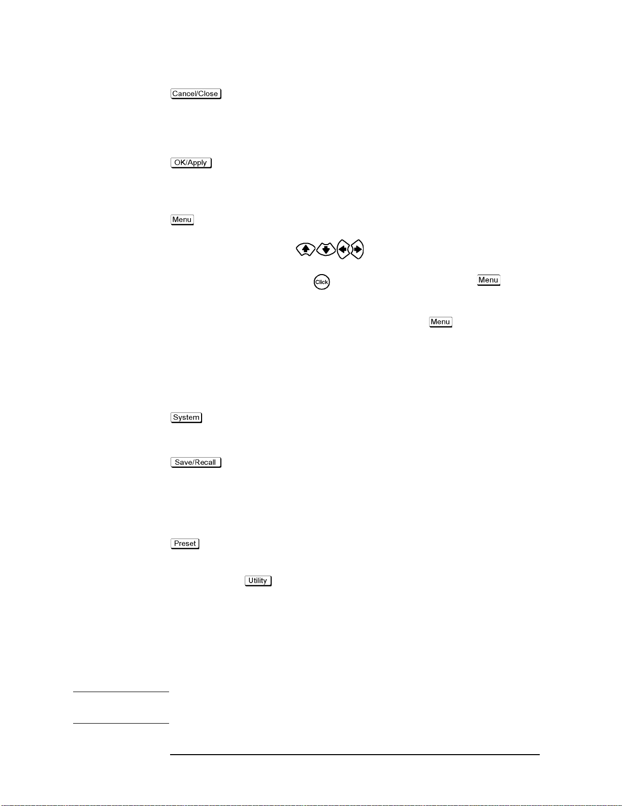
Function Overview
Names and Functions of Front Panel Blocks
key
key
key
Used to close the setup toolbar at the right of the display.
Also, by pressing this key when a dialog box is onscreen,
you can cancel any entry mode and the box closes (i.e., this
key can be used instead of pressing the
in a dialog box).
When you press this key when a dialog box is onscreen, the
entered setting is executed and the box closes. This key can
also be used instead of pressing the
box.
By pressing this key, the leftmost menu opens in the menu
bar at the top of the display. Then, the arrow keys
( ) can be used to move the cursor to other
menus or to the desired item in a menu. Pressing the click
key ( ) selects and executes the item. The key is
used to work with the menu bar when a mouse is not
available.
To close an open menu, press the key again.
Cancel or x button
OK button in a dialog
7. System block (SYSTEM)
This contains a set of keys that are used to set the control and management of the entire
E4991A unit and to save/recall and preset (initialize) files.
key
key
key
Used to show the System Setup toolbar. By working with
this toolbar, you can make control and management
settings for the entire E4991A unit.
Used to show the Save/Recall toolbar. By working with this
toolbar, you can save the E4991A settings, measured data,
calibration/compensation data, image data displayed on the
LCD display, and VBA programs in the E4991A storage
devices (e.g., floppy disk, nonvolatile memory) or recall
them from storage.
Initializes the E4991A to the “Preset State” status.
8. Utility key ( key)
Used to show the Utility toolbar. By working with this toolbar, you can edit and execute
VBA programs or set the E4991A to run an equivalent circuit analysis.
9. Test head interface (TEST HEAD INTERFACE)
This is the interface used to connect the test head. It contains three ports: RF OUT and
PORTs 1 and 2, each of which is an N-type female connector.
NOTE You must not apply either alternate or direct current to the test head interface. Doing this
could cause operational failure.
26 Chapter 2
Page 37

Names and Functions of Front Panel Blocks
Test h ea d
The test head’s DUT port (Figure 2-2) is classified as IEC61010-1 Installation Category I.
Figure 2-2 Test head connected to the E4991A and its DUT port
Function Overview
2. Function Overview
NOTE You must not apply either alternate or direct current to the DUT port. Doing this could
cause operational failure. Pay particular attention to whether the capacitor has been
charged. Fully discharge the device under test before connecting it to the test head DUT
port (or test fixture).
CAUTION Whenever you connect a DUT to or disconnect it from the DUT port for measurement, you
must first turn off the dc bias or set the sweep to the hold state (in sweep hold state, dc bias
is not applied to the DUT). If this step is not taken, the dc bias may destroy the DUT.
Chapter 2 27
Page 38

Function Overview
Names and Functions of Rear Panel Blocks
Names and Functions of Rear Panel Blocks
The names and functions of the E4991A rear panel blocks are shown below.
Figure 2-3 E4991A Rear Panel
1. Power cable receptacle
3. External trigger input connector
2. Unused ports
4. External monitor
output terminal
5. LAN port
6. GPIB connector
7. High stability
frequency
reference output
connector
(Option 1D5)
14. Unused ports
13. Serial number plate
11. Mini-DIN mouse port
12. Mini-DIN keyboard port
10. Printer parallel port
9. Internal reference signal
output connector
8. External reference signal
input connector
28 Chapter 2
Page 39

Function Overview
Names and Functions of Rear Panel Blocks
1. Power cable receptacle (-LINE)
This is the receptacle for connection of the power cable.
For the requirements of the power supply, refer to Chapter 1, “Installation Guide” in the
Installation and Quick Start Guide.
NOTE For the power cable, use the attached 3-wire power cable with grounding prong. For
details, refer to Chapter 1, “Installation Guide” in the Installation and Quick Start Guide.
2. Unused ports (Reserved)
These ports are not available. Do not connect any device here.
3. External trigger input connector (Ext Trig)
Connector type: BNC connector (female)
This is the terminal through which a trigger signal is input to begin execution of
measurement. It detects a trigger by the rising or falling edge following the Low or High
level of a TTL-compatible signal. To trigger measurement with a signal input to this
terminal, you must set the trigger source to EXTERNAL (external trigger input connector).
For details of the input signal requirements of this terminal, see “External trigger input
connector” on page 246.
2. Function Overview
4. External monitor output terminal (VIDEO)
Connector type: 15-pin VGA connector
This is the terminal used for connecting an external color monitor (display device). With a
color monitor connected to this terminal, the same information that is displayed on the
E4991A LCD display can be viewed on the monitor screen.
5. LAN port
Connector type: RJ-45J UTP (Unshielded Twisted Pair) LAN connector
Using this port, the E4991A can be connected to a Local Area Network (LAN). For how to
use the instrument in a LAN, refer to the Programming Manual.
6. GPIB connector
This is a General Purpose Interface Bus (GPIB) connector. An auto-measurement system
can be constructed by connecting an external controller or other equipment via this
connector. For more details on auto-measurement systems that utilize a GPIB, refer to the
Programming Manual.
7. High stability frequency reference output connector (Ref Oven, Option 1D5 only)
Connector type: BNC connector (male)
If Option 1D5 High Stability Frequency Reference is installed in the E4991A, this terminal
outputs the reference signal.
Chapter 2 29
Page 40

Function Overview
Names and Functions of Rear Panel Blocks
NOTE When Option 1D5 is installed, connect this terminal and “8. External reference signal input
terminal (Ext Ref In, 10 MHz 0 dBm)” to the option by using the included
BNC(m)-BNC(m) cable.
8. External reference signal input terminal (Ext Ref In, 10 MHz 0 dBm)
Connector type: BNC connector (male)
This is a signal input terminal used to phase-lock the E4991A test signal to an external
frequency reference signal. The accuracy of test signal frequency can be improved by
inputting the external frequency reference signal to this terminal.
When the external frequency reference signal is input to this input terminal, the E4991A
test signal is automatically phase-locked to its reference signal. When the signal input is no
longer generated, the frequency reference signal in the E4991A is automatically used
instead.
NOTE If option 1D5 has been installed, connect this terminal and “7. High stability frequency
reference output connector (Ref Oven, Option 1D5 only)” to the option by using the
included BNC(m)-BNC(m) cable.
9. Internal reference signal output connector (Int Ref Out)
Connector type: BNC connector (male)
This is an output terminal for the E4991A internal reference signal. By connecting this
terminal and the external reference signal input terminal of other equipment, it can be used
by phase-locking it with the E4991A reference signal.
10. Printer parallel port (PRINTER, Parallel)
This is a 25-pin parallel port used for connecting a printer. With the specified printer
connected to this port, you can print E4991A measurement graphs, measurement values
list, settings list, and other data. For the printers that can be used with the E4991A, see
“Supported Printers” on page 187.
11. Mini-DIN mouse port (MOUSE)
This is a port used to connect a mouse equipped with a Mini-Din connector. Using a
mouse, you can efficiently make various settings by freely moving the cursor across the
E4991A LCD display.
NOTE Use of a mouse other than the one specified for use with the E4991A may lead to operation
error. Be sure to only use the mouse provided by Agilent Technologies.
The mouse has two buttons: left and right, which operate in a different manner. As used in
this manual, the term “clicking with the mouse” indicates pressing the left mouse button.
12. Mini-Din keyboard port (KYBD)
This port is used to connect a Mini-DIN style keyboard. Because alphabetic characters and
symbols directed to the E4991A can be input only through a keyboard, you will need it for
30 Chapter 2
Page 41

Function Overview
Names and Functions of Rear Panel Blocks
such tasks as editing a VBA program or typing a file name.
The arrow and numeric keys on the keyboard operate in the same manner as those on the
E4991A front panel. Thus, you can use the keyboard for cursor navigation instead of
operating the front panel or mouse.
NOTE Use of a keyboard other than the one specified for use with the E4991A may lead to
operation error. Be sure to only use the keyboard provided by Agilent Technologies.
13. Serial number plate
This is a plate showing the serial number, i.e., the production number of the product.
14. Unused ports (Reserved)
These two ports are not available.
2. Function Overview
Chapter 2 31
Page 42

Function Overview
Names and Functions of LCD Display Areas
Names and Functions of LCD Display Areas
The names and functions of the areas of the LCD display are shown below.
Figure 2-4 LCD display
1. Title bar
This displays the title that the user defines and enters. This is useful when printing and
saving the onscreen measurement results.
2. Menu bar
You can make most settings for the E4991A by working with this menu bar in any or all of
the following ways:
o Using the mouse connected to the E4991A, click a menu name on the menu bar. In the
menu that appears, select the desired menu item by clicking with the mouse.
o Press the key in the “6. Entry/navigation block (ENTRY/NAVIGATION)” on
page 25 on the front panel. The leftmost menu of the menu bar opens. Using the
32 Chapter 2
Page 43

Function Overview
Names and Functions of LCD Display Areas
appropriate arrow keys ( ), move the cursor to the desired menu and
menu item. Then press the click key ( ) to select and execute the item.
To dismiss the currently open menu, press the key again.
o While holding down the key on the keyboard connected to the E4991A, type
the alphabetic character underlined in the desired menu name to open the menu. In the
menu that appears, select the desired menu item by typing the underlined character in
the same manner. You do not need to press the key after making a selection in
this way.
Once a menu opens, you can use the following operations instead of the above. First,
use the appropriate arrow keys ( ) on the keyboard to move the cursor up,
down, left, or right over the menus. Then press the key on the keyboard to select
and execute the desired item.
2. Function Overview
Chapter 2 33
Page 44

Function Overview
Names and Functions of LCD Display Areas
Summary of working with the menu bar
Operation Front panel External device
Open the menu on the menu bar
Dismiss the menu bar without execution
Move to the next menu on the left
Move to the next menu on the right
Move the cursor up in a menu
(Rotary knob)
(Disabled) (Disabled)
(Disabled) (Disabled)
(Disabled)
(Disabled)
(Disabled)
(Arrow keys)
Press
Press
Press
Other keys Keyboard Mouse
Press (to open the menu at the far left)
Press Press
(Disabled)
(Disabled)
(Disabled)
Press
and an
alphabetic
character
*1
key
together
Press
Press
Press or an alphabetic character
*1*2
key
Click the desired menu name on the menu bar (to open the menu)
Click the menu name on the currently open menu bar
Move the pointer to the desired menu name on the menu bar
Move the pointer to the desired menu name on the menu bar
Move the pointer to the desired menu name on the menu bar
Move the cursor down in a menu
Select an execute the menu item in the cursor position
*1.The alphabetic character underlined in the menu or menu item name.
*2.When you press an alphabetic character key, the menu or menu item is selected or executed without pressing .
(Disabled)
(Disabled)
Press
Press
(Disabled)
(Disabled) Press Click the menu item
Press or an alphabetic character
*1*2
key
Move the pointer to the desired menu name on the menu bar
name
3. Marker values
This displays values at the marker position (Ñ) on the onscreen active trace.
Marker sweep parameter value (in this example, 100 MHz)
Displays the value of the sweep parameter in the marker
position (in this example, frequency). In this example,
displays the numeric value that represents the position on
the horizontal axis.
34 Chapter 2
Page 45

Function Overview
Names and Functions of LCD Display Areas
Marker measurement parameter value (in this example, 11.4638 W)
Displays the value of the measurement parameter in the
marker position (in this example, |Z| value). In this
example, displays the numeric value that represents the
position on the vertical axis.
4. Setup toolbar
This is a vertical toolbar used to make various settings for the E4991A.
Recalling the desired setup toolbar
You can recall the desired toolbar in any of the following ways:
o Press one of the following hardkeys to show the setup toolbar associated with that key:
• Keys in “4. Measurement block (MEASUREMENT)” on page 23 (except for )
• Keys in “5. Stimulus block (STIMULUS)” on page 24 (except for )
• Keys in “7. System block (SYSTEM)” on page 26 (except for )
•
o Work with the “2. Menu bar” on page 32 to show the setup toolbar associated with a
menu item.
o Right-click to open the shortcut menu (Figure 2-5) and click the desired setup toolbar
name.
2. Function Overview
Figure 2-5 Shortcut menu
You can also bring up the marker shortcut menu (Figure 2-6) by right-clicking a marker (Ñ)
on the display.
Figure 2-6 Marker shortcut menu
Chapter 2 35
Page 46

Function Overview
Names and Functions of LCD Display Areas
Working with the setup toolbar
You can work with a displayed toolbar in any of the following ways:
o Using the mouse connected to the E4991A, directly click the setting item on the setup
toolbar.
o Move the cursor to the desired block in the toolbar by using the Up and Down arrow
keys ( ) in the entry/navigation block on the front panel. Then press the click
key ( ) for selection and execution.
Instead of pressing the and keys, you can turn the rotary knob ( )
counterclockwise or clockwise to achieve the same result. Instead of the click key
( ), you can press the rotary knob ( ) for selection and execution.
To move the cursor over the blocks in a toolbar, use the keys.
o Move the cursor down to the desired block in a toolbar by pressing (or move the
cursor up by holding down and pressing ) on the keyboard connected to
the E4991A. Then press the key for selection and execution. To open a
drop-down list box, hold down while pressing .and then choose an item
from the drop-down list box by releasing and using and .
Summary of working with the setup toolbar
Operation Front panel External device
Other keys Keyboard Mouse
Press one of the following:
Wor k with
the menu
*1
bar
Display the desired setup toolbar
Dismiss the setup toolbar
(Rotary knob)
(Disabled) Work with the
(Disabled) (Disabled) Press Press Right-click to open
(Arrow keys)
*1
menu bar
combination with
the key
(disabled alone)
in
Work with the menu bar
the shortcut menu
and press
Off
*1
Too lba r
36 Chapter 2
Page 47

Names and Functions of LCD Display Areas
Operation Front panel External device
Function Overview
In the toolbar, move the cursor down the blocks
In the toolbar, move the cursor up the blocks
Open a drop-down list box
Move the cursor in a drop-down list box
Enter numeric values
(Rotary knob)
Turn counterclockwise
Turn clockwise
Press
Turn counterclockwise or clockwise
(Disabled) (Disabled) Press
(Arrow keys)
Press
Press
Press
Press or
Other keys Keyboard Mouse
(Disabled) Press Directly click the
(Disabled) Press and
(Disabled) Press and
(Disabled)
desired setting area
in the toolbar
Directly click the
hold down
and
then press
hold down
and
then press
Press or
Press
...
..
desired setting area
in the toolbar
Directly click the drop-down list box
Directly click the desired menu item (to select/execute)
Right-click the
entry box to open
.
the numeric entry
dialog box and
click the desired
buttons
2. Function Overview
Execute numeric data entry with the unit added
Increase/Decrease the entered numeric values
Enter characters (Disabled) Work with the
Enter and select Press
*1.For working with the menu bar, see “2. Menu bar” on page 32.
(Disabled) (Disabled)
Press and turn clockwise or counterclockwise
Press and
then press
or
Keyboard dialog
box displayed by
Keyboard...
the
button
Press
Press ,
, or
(executed)
(Disabled)
(Disabled) Press Work with the
Press Press
Type the unit and press
(executed)
Press or
Right-click the entry box to open the numeric entry dialog box and click the desired buttons
IIII or JJJJ to the
Click
right of the entry
box
Keyboard dialog
box displayed by
the Keyboard...
button
Select/execute by clicking the setting area
Chapter 2 37
Page 48

Function Overview
Names and Functions of LCD Display Areas
5. Trace 1
This is one of the traces that can be displayed simultaneously on the E4991A. The bar
indicating the trace and scale colors of Trace 1 as well as the measurement parameter
names and their units (in this example, |Z| [W]) are displayed in the upper-left corner of the
graph. The asterisk (“*”) to the left of the trace number (1 for this trace) indicates that the
trace is the active trace (target trace for setups). One of the traces on the screen must be the
active trace, and any changes to the trace setup are executed for the active trace. The active
trace is changed in sequential order by pressing the key of “4. Measurement block
(MEASUREMENT)” on page 23.
6. Trace 2
This is one of the traces that can be displayed simultaneously on the E4991A. The bar
indicating the trace and scale colors of Trace 2 as well as the measurement parameter
names and their units (in this example, q
[°]) are displayed in the upper-middle area.
z
7. Markers
These are used to read the values on a trace as numeric values. The value at each marker
position is displayed in the “3. Marker values” on page 34.
8. Scale reference line value
This displays the value of the scale reference line, which is a horizontal dotted line
displayed in the same color as the corresponding trace.
9. Trace 1 axis
This displays the axis and scale of Trace 1.
10. Sweep start value
This displays the current sweep start value.
11. Sweep stop value
This displays the current sweep stop value.
12. Trace 2 axis
This displays the axis and scale of Trace 2.
38 Chapter 2
Page 49

Function Overview
Names and Functions of LCD Display Areas
13. Status bar
This displays the E4991A status information that is critical for the instrument’s operation.
Indicator Description
Bias OFF dc bias is not being applied.
Bias ON dc bias is being applied.
Bias Lmt dc bias output is clamped to the current or voltage limit.
Uncal Calibration is off.
Cal Fix Calibration is on in fixed frequency/fixed power point
mode.
Cal FixR Calibration is on in fixed frequency/user-defined power
point mode.
Cal User Calibration is on in user-defined frequency/user-defined
power point mode.
Comp OFF Compensation is off.
2. Function Overview
Comp ON Compensation is on.
Del xxx Fixture electrical length compensation is applied. (A
numeric value was set for the electrical length of the test
fixture.)
length value in meters. For example,
xxx represents the currently entered electrical
Del 10m indicates that
the fixture’s electrical length is set to 10 millimeters.
Avg xx The point averaging factor is set to xx.
Hold The trigger is on hold.
Manual Waiting for manual trigger.
External Waiting for external trigger.
GPIB Bus Waiting for GPIB trigger (trigger command).
ExtRef The “8. External reference signal input terminal (Ext Ref
In, 10 MHz 0 dBm)” on page 30, and the E4991A test
signal are phase-locked to a reference signal.
Svc The E4991A is in the service mode. Because this mode is
designed for use in self-diagnosis or repair of the E4991A,
the measurement performance guaranteed in the
specification is not obtained. If this indicator is on in the
usual operation mode, the E4991A may have experienced
at failure.
After executing a diagnostic operation,
Svc will appear on
the display. You must shutdown and restart the E4991A
before making measurements.
Chapter 2 39
Page 50

Function Overview
Names and Functions of LCD Display Areas
Indicator Description
Ovld An overload occurred in the measurement circuit. One or
more measurement values are invalid. This indicator goes
on when the device under test is removed or installed
during measurement.
40 Chapter 2
Page 51

3 Setting Measurement Conditions
3. Setting Measurement
Condition
This chapter describes the method used to set up the measurement conditions (test signal
and sweep) for the Agilent E4991A impedance/material analyzer.
41
Page 52

Setting Measurement Conditions
Initialization of E4991A (presetting)
Initialization of E4991A (presetting)
The E4991A has an initialization state called the “Preset State.”
It is always possible to return the E4991A to its preset state by taking one of the following
actions:
• Right-click to open the shortcut menu, and click
•Click
•Press in the SYSTEM block on the front panel.
For more details on the E4991A’s initial settings, including the preset state, refer to
Chapter G, “Initial Settings,” on page 417.
System-Preset from the menu bar.
Preset-Execute.
42 Chapter 3
Page 53

Setting Material Measurement Parameter (Option 002 only)
Setting Material Measurement Parameter (Option 002 only)
When you take a material measurement (permittivity or permeability measurement) with
the E4991A and “Option 002 material measurement,” the following setups must first be
completed.
Procedure
Step 1. Select the type of material measurement
Setting Measurement Conditions
a. Right-click to open the shortcut menu and click
b. Click the
c. Click to open the
Material Type Box Material Measurement Type
Impedance Impedance measurement (measurement of
Permittivity Permittivity measurement
Permeability Permeability measurement
Material Option Menu button.
Material Type box and click on the material measurement type.
Step 2. Enter material dimensions
Using the numeric entry dialog box that appears by right-clicking inside the setting box
described below (or using the ENTRY/NAVIGATION block key of the front panel), enter
the necessary material dimensions:
Material Dimension Setting Box Value to Enter
Thickness Thickness of dielectric material t [m] (see Figure
Height Height of magnetic material h [m] (see Figure
Utility (or press ).
general impedance parameters except for
permittivity and permeability).
3-1)
3-2)
3. Setting Measurement
Condition
Inner Diameter Inner diameter of magnetic material b [m] (see
Figure 3-2)
Outer Diameter Outer diameter of magnetic material c [m] (see
Figure 3-2)
Chapter 3 43
Page 54

Setting Measurement Conditions
Setting Material Measurement Parameter (Option 002 only)
Figure 3-1 Material shape parameter for dielectric material
Figure 3-2 Material shape parameter for magnetic material
44 Chapter 3
Page 55

Setting Measurement Conditions
Selection and Confirmation of Target Trace (Active Trace)
Selection and Confirmation of Target Trace (Active Trace)
It is necessary to first select a target trace to set among the multiple traces shown on the
display. This target trace is referred to as the “Active Trace.”
Selecting Active Trace
You can select the active trace by taking any of the following actions:
• In the split display mode, click inside the window frame of the trace you want to activate.
• In a overlay display mode, click the name area of the measurement parameter (e.g.
qz [°]
) or click the measurement value axis (vertical axis) of the trace you want to
activate. If you place the cursor in this area, it will change from to .
• Right-click to open the shortcut menu and click
indicates trace number).
•Click
• Press in the MEASUREMENT-block on the front panel (each press changes
Trace-Scaler # or Trace-Complex # (# indicates trace number) from the menu
bar.
the active trace in sequential order.
Trace-Scaler # or Trace-Complex # (#
2:
Identifying Active Trace
The selected active trace can be identified in the following ways:
• An asterisk (“
parameter (e.g.
• The active trace’s number is indicated in a window at the top of five setup toolbars:
Meas/Format, Scale, Display, Marker, Marker Function.
• The active trace is indicated together with its number in the title area (at the top of the
display) in the preset state.
*”) appears to the left of the name area of the active trace’s measurement
2: qz [°]).
3. Setting Measurement
Condition
NOTE An operation done in a setup tool bar where the active trace number is not displayed shall
be executed not for a particular trace but commonly for all traces on the display.
Chapter 3 45
Page 56

Setting Measurement Conditions
Selecting Sweep Parameter
Selecting Sweep Parameter
The sweep parameter of the source can be selected from among frequency, source power
(level), dc bias voltage and current.
NOTE Option 001 must be installed to sweep by dc bias voltage or current.
Procedure
Step 1. Right-click to open the shortcut menu and click Sweep Setup (or press ).
Step 2. Click and open the
Sweep Parameter box Sweep Parameter
Frequency Frequency
Power Source power (level)
Bias Voltage dc bias voltage (option 001 only)
Bias Current dc bias current (option 001 only)
Sweep Parameter box and click to select the sweep parameter.
46 Chapter 3
Page 57

Using Time as Sweep Parameter (Zero Span Sweep)
Measurement using time as the sweep parameter can be executed by setting the sweep
parameter to zero. This sweep is called Zero Span sweep.
Procedure
Step 1. Set the sweep span to zero:
Setting Measurement Conditions
Using Time as Sweep Parameter (Zero Span Sweep)
a. Right-click to open the shortcut menu and click
b. Using the numeric entry dialog box by right-clicking inside the
ENTRY/NAVIGATION block keys on the front panel), enter zero as the sweep span
value.
Step 2. Set sweep time:
a. Right-click to open the shortcut menu, and click
b. Click the
c. Using the numeric entry dialog box by right-clicking inside the
using the ENTRY/NAVIGATION block keys on the front panel), enter the sweep time
(i.e., sweep span in the time sweep).
NOTE If the number of measurement points is set to the maximum value (801), the sweep time
can be set up to 16,080 second (approximately 4.5 hours).
Sweep Time button.
Start/Stop (or press ).
Span box (or using the
Sweep Setup (or press ).
Sweep Time box (or
3. Setting Measurement
Condition
Chapter 3 47
Page 58

Setting Measurement Conditions
Selecting Sweep Type (Linear/Log/Segment)
Selecting Sweep Type (Linear/Log/Segment)
You can select the sweep type by following the procedure below.
Procedure
Step 1. Right-click to open the shortcut menu and click Sweep Setup (or press ).
Step 2. Right-click to open the shortcut menu and click to select the Sweep Type box.
Sweep Type Box Sweep Type
Linear Linear sweep
Log Log sweep
Segment Segment sweep
NOTE When the oscillator level (power) or dc bias has already been selected as a sweep
parameter, the sweep type is fixed to linear sweep and cannot be changed. For more details
on selecting the sweep parameter, see “Selecting Sweep Parameter” on page 46.
If the segment sweep table has not been prepared, the segment sweep cannot be selected
(when the segment sweep table has been not prepared, the
if the
Sweep Type box is opened). For more details on preparing the segment sweep table,
Segment is not displayed, even
see “Sweeping a Plural Number of Sweep Areas under Different Conditions at One Time
(Segment Sweep)” on page 66.
48 Chapter 3
Page 59

Setting Measurement Conditions
Selecting Sweep Direction
Selecting Sweep Direction
The characteristics of a device under test (DUT) having the hysteresis feature for sweep
parameter can be observed from the appropriate sweep direction.
You can select the sweep direction by following the procedure below.
Procedure
Step 1. Right-click to open the shortcut menu and click Sweep Setup (or press ).
Step 2. Click the Sweep Direction button and select the Sweep Direction.
Sweep Direction Button Sweep Direction Setup
Sweep Direction [Up] Upward (in the direction from sweep start value
to sweep stop value)
Sweep Direction [Down] Downward (in the direction from sweep stop
value to sweep start value)
3. Setting Measurement
Condition
Chapter 3 49
Page 60

Setting Measurement Conditions
Measurement Waiting Time/Sweep Time Setting
Measurement Waiting Time/Sweep Time Setting
A time delay can be set for the period after the sweep is triggered but before the actual
sweep starts (sweep delay). Furthermore, a time delay can also be set for the period after a
signal is applied to a DUT but before actual measurement starts (point delay). This
function is useful, for example, when a certain period is required before the characteristics
of the DUT can become stable after a signal is applied. Another application of this function
is to observe the changes in a DUT’s impedance over time for a long span.
Figure 3-3 shows the definitions of sweep time, sweep delay time, point delay time, and
segment delay time.
Figure 3-3 Definition of measurement waiting time
50 Chapter 3
Page 61

Setting Measurement Conditions
Measurement Waiting Time/Sweep Time Setting
Procedure
Step 1. Right-click to open the shortcut menu and click the Sweep Setup (or press ).
Step 2. Click the
Step 3. Using the numeric entry dialog box by right-clicking inside the
Sweep Setup button.
Sweep Time box (or using
the ENTRY/NAVIGATION block key on the front panel), enter the sweep or delay time.
Sweep Time Setting Box Input Value
Sweep Time Sweep time (time period for an entire sweep)
Point Delay Point delay time (time delay for each
measurement point)
Segment Delay Segment delay time (time delay for each
segment).
Sweep Delay Sweep delay time (time delay for each sweep).
Setting the time period for an entire sweep (
automatically set equal time delays at a measurement point (
When the measurement point delay time (
Delay
), or sweep delay time (Sweep Delay) is changed, the sweep time (Sweep Time)
Sweep Time) makes it possible to
Point Delay).
Point Delay), segment delay time (Segment
setting is automatically changed.
NOTE Segment delay time is only effective when the sweep type is set to segment sweep. For
details on segment sweep, refer to “Sweeping a Plural Number of Sweep Areas under
Different Conditions at One Time (Segment Sweep)” on page 66.
3. Setting Measurement
Condition
Chapter 3 51
Page 62

Setting Measurement Conditions
Setting Sweep Range
Setting Sweep Range
There are two ways to set the sweep area. One is setting according to the start and stop
values, and the other is setting according to the center and span values.
Figure 3-4 Sweep Area Setting
Procedure
Step 1. Right-click to open the shortcut menu and click Start/Stop (or press ).
Step 2. When setting the sweep area according to Start/Stop values, change the values in the Start
box and
values, change the values in the
Sweep Area Setting Box Input Value
Start Sweep start value.
Stop Sweep stop value.
Center Sweep center value.
Span Sweep span value.
You can use any of the following methods to change the value in the box:
• Right-click in the box and enter the set value by clicking the numerical and unit buttons
• Click the up or down (s or t) button to increase or decease the sweep area setting
• After all character strings in a box have been selected (displayed in reverse), press the
Stop box in the tool bar. When setting the sweep area according to Center/Span
Center box and Span box in tool bar.
that appear.
value.
keys in the ENTRY/NAVIGATION block to enter the sweep area setting value. To set
up the sweep start value of 100 MHz, for example, press in the
Start
52 Chapter 3
Page 63

Setting Measurement Conditions
Setting Sweep Range
box one-by-one.
• When all character strings in the box are selected (displayed in reverse), place the
cursor at the top of the character string by pressing or and pressing the up and
down buttons or turning the rotary knob to increase and decease the
sweep area setting value.
• When all character strings in the box are selected (displayed in reverse), enter the
sweep area setting value with the external keyboard. To enter the sweep start value of
100 MHz, for example, press (“M” should be typed as a capital letter)
in the
Start box and finish the entry by pressing .
NOTE If you enter the sweep start and sweep stop values, the sweep center and sweep span values
will be automatically calculated based on those values and displayed in their respective
boxes. On the other hand, if you enter the sweep center and sweep span values, the sweep
start and sweep stop values will be automatically calculated based on the entered sweep
center and sweep span values and displayed in their respective boxes.
You cannot set up a sweep start value that is larger than the sweep stop value. If you want
to sweep from a higher to a lower value, you should first set up the sweep area from a
lower to a higher value and then set the sweep direction to “[Down].” For details on setting
the sweep direction, see “Selecting Sweep Direction” on page 49.
3. Setting Measurement
Condition
Chapter 3 53
Page 64

Setting Measurement Conditions
Setting Sweep Area with Marker
Setting Sweep Area with Marker
You can assign the position of the active marker on a trace (stimulus value) in the same
way as setting sweep start value, sweep stop value, or sweep center value. It is also
possible to assign the distance between Marker R and Marker 1 (or 2 - 8), which is the
difference between stimulus values, in the same way as setting sweep span value (Figure
3-5).
54 Chapter 3
Page 65

Figure 3-5 Sweep Area Setting with the Marker
Setting Measurement Conditions
Setting Sweep Area with Marker
3. Setting Measurement
Condition
Chapter 3 55
Page 66

Setting Measurement Conditions
Setting Sweep Area with Marker
Procedure
Step 1. Place the active marker on the new sweep start, sweep stop, or sweep center. To set a sweep
span, place Marker R and Marker 1 (or 2-8) on the trace points corresponding to the new
sweep span and set the marker delta mode to delta or fixed delta. At this time, set Marker 1
(or 2-8) to active status (marker display:
Chapter 6, “Analysis of Measurement Results,” on page 127.
Ñ). For details on how to use the marker, see
Step 2. Right-click to open the shortcut menu and click
Marker (or press ).
Step 3. Click the Marker To Menu button.
Step 4. Set the position (distance) of markers on a new sweep area by clicking any of the following
buttons for assigning marker values.
Button Assigning Marker Value Sweep Area Display Mode
Start Assign the stimulus value of the active marker as
the sweep start value. As a result, the position of
the marker establishes a new sweep start point.
Stop Assign the stimulus value of the active marker as
the sweep stop value. As a result, the position of
the marker establishes a new sweep stop point.
Center Assign the stimulus value of the active marker as
the sweep center value. As a result, the position
of the marker establishes a new sweep center
point.
Delta To Span For Marker R and the active marker (one of
Markers 1 to 8), the smaller marker stimulus
value is assigned as the sweep start value and the
larger one is assigned as the sweep stop value.
As a result, the sweep range between Marker R
and the active marker establishes a new sweep
span.
NOTE After the sweep area is changed, no trace is displayed in the new sweep area until a new
measurement is taken.
56 Chapter 3
Page 67

Setting Number of Points (NOP)
Setting Number of Points (NOP)
The number of points (NOP) per sweep is set by following the procedure below.
Procedure
Step 1. Right-click to open the shortcut menu and click Sweep Setup (or press ).
Step 2. Using the numeric entry dialog box that appears by right-clicking inside the Number Of
Points
box (or using the ENTRY/NAVIGATION block keys on the front panel), enter the
number of points.
NOTE Number of points can be set as an integer from 2 to 801.
Number of points is set by the segment sweep table when the sweep type is segment
(segment sweep). For setting the segment sweep table, see “Sweeping a Plural Number of
Sweep Areas under Different Conditions at One Time (Segment Sweep)” on page 66.
Setting Measurement Conditions
3. Setting Measurement
Condition
Chapter 3 57
Page 68

Setting Measurement Conditions
Oscillator Level Setting
Oscillator Level Setting
Definition of Oscillator Level Setting
When oscillator is not the sweep parameter (i.e., it’s a fixed parameter), the oscillator unit
can be selected from power (dBm), voltage (V) or current (A) depending on the oscillator
level setting. Oscillator level units and the definition of their setting values are given
below.
Oscillator Level
Definition of Oscillator Level Setting Value
Unit (Osc Unit)
Power [dBm] Power level P
W resistor connected to the measurement terminal (P
the 50
P
).
50
Vo l ta g e [ V ] Voltage value V
is equivalent to the power level P50 consumed in
set
set
terminal is connected to the 50
value is approximately equal to the voltage when the measurement
terminal is open
Current [A] Current value I
*1
set
terminal is connected to the 50
value is approximately equal to the voltage when the measurement
terminal is shorted
*1.When measuring a DUT having a value of Z
actually applied to the DUT as follows.
Z
x
set
------------- -----
´=
Zx50+
------------ ------
´=
Z
x
50
50+
VxV
*2.When measuring a DUT having a value of Z
actually flowing into the DUT as follows.
I
xIset
: Setting value of the oscillator level [V])
(V
set
: Setting value of the oscillator level [A])
(I
set
=
set
is twice the value of V50 when the measurement
W resistor (V
= V50 ´ 2). This
set
.
is twice the value of I50 when the measurement
W resistor (I
*2
.
[W], you can calculate the voltage V
x
[W], you can calculate the current I
x
= I50 ´ 2). This
set
[V]
x
[A]
x
The accuracies of the levels calculated by Equations *1 and *2 are as follows.
58 Chapter 3
Page 69

A
------
æö
30 10
20
ç÷
èø
1–
100 B+´+±
[%] (Typical)
A: oscillator level accuracy [dB]
B: impedance measurement accuracy [%]
Procedure
Follow the procedure below to specify a fixed oscillator level (AC level) when the sweep
parameter is any item other than oscillator level (i.e., frequency or dc bias).
Step 1. Selecting oscillator level unit
Setting Measurement Conditions
Oscillator Level Setting
a. Right-click to open the shortcut menu, and click
b. Click and open the
Osc Unit Box Oscillator Level Unit
Power Power (dBm)
Volt age Voltage (V)
Current Current (A)
Osc Unit box and select the desired oscillator level unit.
Source (or press ).
NOTE The oscillator level unit that you set is used for sweeping the oscillator level and also for
setting the fixed oscillator level, which is used for sweeping any parameter other than
oscillator level.
Step 2. Oscillator Level Setting
Using the numeric entry dialog box that appears by right-clicking inside the
Osc Level box
(or using the ENTRY/NAVIGATION block keys on the front panel), enter the Osc level.
For example, use the ENTRY/NAVIGATION block keys to enter the oscillator level of
-10 dBm by pressing to delete the character string in the box and then pressing
.
3. Setting Measurement
Condition
NOTE For more details on the entry area for the oscillator level and resolution, see “Specification
and Reference Data.”
Chapter 3 59
Page 70

Setting Measurement Conditions
Setting and Applying dc Bias
Setting and Applying dc Bias
Follow the procedure below to apply dc bias to the DUT.
Procedure
CAUTION Whenever you connect a DUT to or disconnect it from the E4991A for measurement, you
must first turn off the dc bias or set the sweep to the hold state (in sweep hold state, dc bias
is not applied to the DUT). If this step is not taken, the dc bias may destroy the device.
Step 1. Select the dc Bias Mode:
a. Right-click to open the shortcut menu and click
b. Click to open the
Bias Source Box dc Bias Mode
Current Current Source
Volt age Voltage Source
Step 2. Set the dc Bias Level
Use the numeric entry dialog box that appears by right-clicking inside the
(or the ENTRY/NAVIGATION block keys on the front panel) to enter the dcBias level.
Step 3. Set the dc Bias Limit
Use the numeric entry dialog box that appears by right-clicking inside the
(or the ENTRY/NAVIGATION block keys on the front panel) to enter the dc Bias Limit
value.
Step 4. Apply dc Bias
a. Click the
dc Bias button and turn the dc Bias on.
If this operation is made during a sweep measurement, the sweep mode will
automatically stop the sweep. dc Bias will not be applied after the sweep is stopped.
Source (or press ).
Bias Source box and then click to select the dc Bias Mode:
Bias Level box
Bias Limit box
b. Execute sweep measurement according to the operating procedures described in
“Single Sweep, Continuous Sweep and Sweep Stop” on page 63.
Step 5. Monitor dc Bias Level
The level of dc bias applied to the DUT can be displayed by the following procedure.
a. Right-click to open the shortcut menu and click
b. Click the
Bias Monitor button and turn the dc bias level monitor on.
c. Right-click to open the shortcut menu and click
Marker 1 appears on the trace and the dc bias level monitor value at the marker point is
displayed at the top of the screen area. For more details on setting and using markers,
refer to Chapter 6, “Analysis of Measurement Results,” on page 127.
60 Chapter 3
Source (or press ).
Marker.
Page 71

Setting Measurement Conditions
Setting the Trigger Source To Start Sweep
Setting the Trigger Source To Start Sweep
Set up the signal source to execute sweep start (i.e., the trigger source) by following the
procedure below.
Procedure
Step 1. Right-click to open the shortcut menu and click Trigger S etup (or press ).
Step 2. Click to open the Trigger Source Box and select the desired trigger source.
Trigger Source Box Trigger Source
Internal Internal continuous trigger generated
automatically by the E4991A.
Manual Manual trigger generated by clicking the Manual
button on the Tr i gger S e t u p toolbar or
Trigg er
by pressing
*1
.
External External trigger implemented upon detecting
TTL signal coming into external trigger input
connector of rear panel.
GPIB Bus GPIB trigger implemented by trigger command
to start measurement sent via GPIB.
*1.The manual trigger can also be executed by clicking Trigger-Trigger from the menu bar
or by clicking
Trigger from the shortcut menu displayed by pressing the right button.
NOTE For more details on the characteristics of the signal for an external trigger, see “Chapter 11,
“Specifications and Supplemental Information,” on page 227.”
For more details on using GPIB, see Programming Manual.
3. Setting Measurement
Condition
Chapter 3 61
Page 72

Setting Measurement Conditions
Selecting Trigger Target (Trigger Event)
Selecting Trigger Target (Trigger Event)
You may select the target for trigger generation (trigger event) from single sweep (sweep
trigger), one-point measurement (measurement point trigger), or one-segment
measurement (segment trigger).
NOTE The trigger event is fixed to On Sweep and cannot be changed when Internal is selected as
the trigger source in “Setting the Trigger Source To Start Sweep” on page 61.
Procedure
Step 1. Right-click to open the shortcut menu and click Trigger Setup (or press ).
Step 2. Click and open the
Trigger Event List Trigger Event
On Sweep Sweep trigger (single sweep is made with each
On Point Measurement point trigger (one point is
On Segment Segment trigger (one segment is measured with
Trigger Event Box and click to select the desired Trigger Event.
trigger).
measured with each trigger).
each trigger).
NOTE It is necessary to prepare a segment sweep table before using a segment trigger. For more
details on preparing a segment sweep table, see “Sweeping a Plural Number of Sweep
Areas under Different Conditions at One Time (Segment Sweep)” on page 66.
62 Chapter 3
Page 73

Setting Measurement Conditions
Single Sweep, Continuous Sweep and Sweep Stop
Single Sweep, Continuous Sweep and Sweep Stop
You may select the type of sweep execution upon trigger generation from single sweep,
continuous sweep, and sweep stop.
Procedure
Step 1. Right-click to open the shortcut menu and click Trigger S etup (or press ).
Step 2. Select the sweep mode by clicking one of the three buttons for sweep mode selection.
Sweep Mode Selection button Sweep Mode
Hold Sweep stop (sweep is immediately stopped and
not restarted even if a trigger is generated).
Single Single sweep (single sweep is triggered and
when the sweep finishes Sweep Stop mode is
invoked; if you press this button during the
sweep, this sweep is stopped and a new single
sweep is executed).
Continuous Continuous sweep (sweep is continuously
repeated by trigger generation).
3. Setting Measurement
Condition
NOTE A check mark (Ö) to the left of the sweep mode selection button indicates the mode that is
currently selected and executed.
Chapter 3 63
Page 74

Setting Measurement Conditions
Selecting Polarity of External Trigger Input Signal
Selecting Polarity of External Trigger Input Signal
You can select the polarity for trigger signal detection by the external trigger input
connector on the rear panel by following the procedure below.
Procedure
Step 1. Right-click to open the shortcut menu and click Trigger Setup (or press ).
Step 2. Click the Trigger Polarity Button and select the external trigger signal polarity.
Trigger Polarity Button External Trigger Signal Polarity
Positive Positive polarity (detects increasing TTL signal
and triggers).
Negative Negative polarity (detects decreasing TTL signal
and triggers).
64 Chapter 3
Page 75

Setting Measurement Conditions
CW Frequency Setting
CW Frequency Setting
When you set the sweep parameter to one other than frequency (source level, dc bias
voltage, or dc bias current), set the fixed measurement frequency (CW frequency) by
following the procedure below.
NOTE When the sweep parameter is set to frequency, it is not possible to set CW frequency. In
order to set CW frequency, you should preset the sweep parameter to one other than
frequency according to “Selecting Sweep Parameter” on page 46.
Procedure
Step 1. Right-click to open the shortcut menu and click Source (or press ).
Step 2. Using the numeric entry dialog box that appears by right-clicking inside the CW Freq box
(or using the ENTRY/NAVIGATION block keys on the front panel), enter the CW
frequency.
For example, to set the CW frequency, click
one-by-one with the ENTRY/NAVIGATION block keys on the front
panel).
100M in the numeric entry dialog box (or press
3. Setting Measurement
Condition
Chapter 3 65
Page 76

Setting Measurement Conditions
Sweeping a Plural Number of Sweep Areas under Different Conditions at One Time (Segment Sweep)
Sweeping a Plural Number of Sweep Areas under Different Conditions at One Time (Segment Sweep)
When linear sweep or log sweep is selected as the sweep type in frequency sweep, certain
measurement conditions like the point averaging factor and the oscillator level are uniform
over the entire single sweep. Consequently, it is not possible to change such settings for a
particular area.
In segment sweep, on the other hand, a plural number of frequency areas, which are called
“segments,” can be individually set by users. In this case, certain measurement conditions
(i.e., number of points, point averaging factor, source unit/oscillator level, DC bias
mode/level/limit) can be set for each segment, and the entire series of such segment setups
can be sequentially executed as a single sweep (Figure 3-6).
By using this feature, it is possible to take a sweep measurement in only the desired area
and to skip the frequency areas that you do not need to measure. It is also possible to set
optimal measurement conditions for each designated segment. For example, you can
increase the point averaging factor and number of points for segments that require
measurements with higher stability and more accurate frequency resolution (as resonance
point). For segments without such stringent measurement requirements, you can set the
conditions to enable high-speed measurement.
Figure 3-6 Concept of Segment Sweep
66 Chapter 3
Page 77

Sweeping a Plural Number of Sweep Areas under Different Conditions at
Procedure
Step 1. Preparation of segment table
Setting Measurement Conditions
One Time (Segment Sweep)
a. Right-click to open the shortcut menu and click
b. Click the
Segment Table Menu button.
The segment sweep setup table (Figure 3-7) is displayed.
Figure 3-7 Segment Sweep Setup Table
Sweep Setup (or press ).
3. Setting Measurement
Condition
c. Click the
Add Segment button to add a new segment in the Segment Sweep Table.
The default values for the first segment are listed in the columns of Chapter G, “Initial Settings,” on page 417. When the table already has segments, the last segment in the table is copied to create a new segment.
d. Edit the added segment using the following buttons and boxes.
Segment Sweep Setting Button/Box Setting Function
Start spin box This sets sweep start frequency of segment.
Stop spin box This sets sweep stop frequency of segment.
Number Of Points spin box This sets number of points of segment.
Point Average spin box This sets point averaging factor of segment.
Delete Segment button This deletes the segment designated in the
Segment No. box from the table.
Chapter 3 67
Page 78

Setting Measurement Conditions
Sweeping a Plural Number of Sweep Areas under Different Conditions at
One Time (Segment Sweep)
Segment Sweep Setting Button/Box Setting Function
More button This opens the toolbar showing the buttons
described below.
<< button This returns to the toolbar showing the buttons
described above.
Osc Level spin box This sets source level of segment.
Osc Unit list box This selects source level unit in segment sweep
from among
Bias Level spin box This sets DC bias level of segment.
Bias limit spin box This sets DC bias limit of segment.
Bias Source list box This selects either Volta ge or Current as DC
bias mode in segment sweep.
*1.This is a setting common to all segments (cannot be set individually for each segment).
Power, Volt age and Current.
*1
*1
To change the numeric value in a spin box, right-click in the box to open and use the
numeric entry dialog box, or use the ENTRY/NAVIGATION block keys on the front
panel.
To select an item in a box, click to open the box and then click to select the item.
The maximum number of segments in a table is 16. The maximum number of
measurement points in the entire table is 801.
e. Repeat step c and step d to complete the required segments.
To modify one of the created segments, enter the segment number in the
Segment No.
spin box and edit the segment in accordance with step d.
NOTE You can directly call up the setup box for changing an item’s value by clicking the current
value in the segment table on the screen (Figure 3-7).
68 Chapter 3
Page 79

Sweeping a Plural Number of Sweep Areas under Different Conditions at
Figure 3-8 Area to Click and Call Setup Box (Inside the Frame)
Setting Measurement Conditions
One Time (Segment Sweep)
Step 2. Selecting segment as a sweep type
a. Right-click to open the shortcut menu and click
b. Click to open the
Sweep Type box and then select Segment (Segment Sweep).
Sweep Setup (or press ).
Step 3. Setting a graph’s horizontal axis in the segment sweep
Click the
Segment Display button and select the appropriate setting for the graph’s
horizontal axis by referring to the table below (See Figure 3-9).
Segment Display Button Graphic Horizontal Axis Display
Segment Display [Order Base] Order base (defines the horizontal axis at equal
intervals in order of measurement).
Segment Display [Freq Base] Frequency base (defines the horizontal axis as a
linear frequency axis with the minimum
frequency at the left end and the maximum
frequency at the right end of the sweep table).
Segment Display [Log Freq Base] Log frequency base (defines the horizontal axis
as a log frequency axis with the minimum
frequency at the left end and the maximum
frequency at the right end of the sweep table).
3. Setting Measurement
Condition
Chapter 3 69
Page 80

Setting Measurement Conditions
Sweeping a Plural Number of Sweep Areas under Different Conditions at
One Time (Segment Sweep)
Figure 3-9 Order Base Display and Frequency Base Display
70 Chapter 3
Page 81

Averaging Measurement Results
Averaging Plural Sweeps (Sweep-to-Sweep Averaging)
Sweep-to-sweep averaging means to average the data (vector quantities) of all points based
on the index average of a continuous sweep weighed with an averaging factor designated
by the user. Sweep-to-sweep averaging is performed according to Equation 3-1:
Equation 3-1 Sweep-to-sweep averaging calculation formula
Setting Measurement Conditions
Averaging Measurement Results
S
n
A
where:
A
= Calculation result of sweep-to-sweep averaging from n-times sweeping at the
n
measurement point (vector quantity).
S
= Measurement value from n-times sweeping at the measurement point (vector
n
quantity).
F = Sweep-to-sweep averaging n-times.
Set the sweep-to-sweep averaging by following the procedure below.
Procedure
Step 1. Right-click to open the shortcut menu and click
Step 2. Click the Sweep Average button to turn the sweep-to-sweep averaging on.
Step 3. Enter the number of times for sweep-to-sweep averaging with the numeric entry dialog box
that appears by right-clicking inside the
ENTRY/NAVIGATION block keys on the front panel.
For example, to set the sweep-to-sweep averaging number of times to 8, click
in the numeric entry dialog box (or press using the ENTRY/NAVIGATION
block keys on the front panel).
-----
n
F
1
æö
---
1
–
èø
A
´+=
F
n 1–
Meas/Format (or press ).
Swp Avg Count box or with the
8 and Enter
3. Setting Measurement
Condition
Figure 3-10 Displaying Sweep-to-Sweep Averaging Counter
Chapter 3 71
Page 82

Setting Measurement Conditions
Averaging Measurement Results
NOTE You may set the number of times for sweep-to-sweep averaging in integers from 1 to 999.
If you click the
Sweep Average Restart button while performing sweep-to-sweep
averaging, n in Equation 3-1 will be reset to 1.
72 Chapter 3
Page 83

Averaging by Each Measurement Point (Point Averaging)
With point averaging, each measurement point is measured the number of times designated
by the user, and the average measured vector quantity sets the value for that point.
Accordingly, sweep time becomes longer in proportion to an increased number of times set
for averaging. Point averaging is performed according to Equation 3-2.
Equation 3-2 Point Averaging Calculation Formula
F
1
---
M
=
where;
M = Calculation result of point averaging at the measurement point (vector quantity).
S
= Measurement value from n-times sweeping at the measurement point (vector
n
quantity).
F = Point averaging n-times.
Set point averaging by following the procedure below.
S
n
å
F
n 1=
Setting Measurement Conditions
Averaging Measurement Results
Procedure
Step 1. Right-click to open the shortcut menu and click
Step 2. Enter the number of times for point averaging with the numeric entry dialog box that
appears by right-clicking inside the
block keys on the front panel.
For example, to set the point averaging number of times to 8, click
numeric entry dialog box (or press using the ENTRY/NAVIGATION block
keys on the front panel).
Figure 3-11 Displaying Point Averaging Number
Point Avg box or with the ENTRY/NAVIGATION
3. Setting Measurement
Condition
Sweep Setup (or press )
8 and Enter in the
NOTE You may set the number of times for point averaging in integers from 1 to 100.
Chapter 3 73
Page 84

Setting Measurement Conditions
Averaging Measurement Results
74 Chapter 3
Page 85

4 Calibration and Compensation
It is necessary to perform calibration and compensation before using the Agilent E4991A
to take measurements.
75
4. Calibration and
Compensation
Page 86

Calibration and Compensation
Outline of Calibration and Compensation Functions
Outline of Calibration and Compensation Functions
Any measuring instrument, however sophisticated it may be, has a certain degree of error
in actual use. The functions of calibration and compensation of the E4991A minimize
possible errors and assure higher measurement accuracy.
Types of Calibration and Compensation
The E4991A has five calibration/compensation functions as shown in Table 4-1.
Table 4-1 Calibration/Compensation Functions of E4991A
Calibration/compensation functions
Calibration of open/short/load All calibration data are measured by
Calibration of low-loss capacitor The calibration data are measured by
Port extension compensation
Fixture electrical length compensation
Execution Method Effect
connecting three standards (open, short,
and load) one-by-one to the desired
reference plane (connector). This
reference plane is called the calibration
reference plane.
connecting the low-loss capacitor to the
calibration reference plane after
completing the open/short/load
calibration. This can only be executed
when the 7-mm connector is used as the
calibration reference plane.
*1
When the port is extended from the
compensation reference plane by a coaxial
cable, enter the delay time (sec.) of the
extension as a numerical value and regard
the corresponding extended portion as a
distributed parameter circuit without loss.
Electrical length is entered as a numerical
value. Since the electrical length of an
exclusive-use test fixture is registered in
the E4991A, the necessary electrical
length can be set by simply selecting the
model number of the test fixture used.
The error factors within the area from the
instrument body to the calibration
reference plane are removed. If calibration
is performed for the connector of the DUT,
it is not necessary to execute any further
calibration/compensation.
This decreases high Q (low-loss
coefficient) above the frequency band near
1 GHz, which is difficult to decrease by
only using open/short/load calibration.
This compensates additional error caused
by phase shift in the area of the port
extended by the coaxial cable.
This compensates additional errors caused by phase shift at the test fixture.
Compensation of open/short All compensation data are measured after
bringing the tested device’s connecting
terminal to the open and/or short state.
*1.Port extension compensation is not required when an Agilent text fixture is directly connected to the 7-mm termi-
nal of the test head.
This removes any additional measurement error caused by residual impedance in the test fixture.
76 Chapter 4
Page 87

Calibration Reference Plane and Calibration Standard
Before choosing which method of calibration and compensation to use, you must first
decide where to set the calibration reference plane. The most common calibration reference
plane is the 7-mm terminal plane in front of the test head. In this case, you may use open,
short, load, and low-loss capacitor standards included in the calibration kit supplied with
the E4991A. You may also use the terminal plane as a calibration reference plane for
connecting the tested device. However, you need to use a calibration standard (working
standard) that has a similar shape to the device under test.
Figure 4-1 Calibration Reference Plane
Calibration and Compensation
Outline of Calibration and Compensation Functions
Chapter 4 77
4. Calibration and
Compensation
Page 88

Calibration and Compensation
Outline of Calibration and Compensation Functions
Table 4-2 Calibration Reference Plane and Necessary Calibration/Compensation
Calibration Reference Plane
7-mm terminal for test head (A)
Terminal for connecting to the DUT (B)
*1.In extending the coaxial cable from the 7-mm terminal of test head to the test fixture, it is possible to compensate
the port extension for the extended portion. For more on the port extension, see “Port Extension Compensation” on
page 86.
*2.Since the low-loss capacitor is the 7-mm type, this calibration can only be executed when the calibration reference
plane is a 7-mm terminal.
*3.When using an exclusive-use test fixture with a registered electrical length, you only need to select the model num-
ber of the fixture.
*4.This is a reference device that has a similar shape to the device under test.
Necessary Calibration/Compensation Place and Method of Execution
*1
1. Calibration for open/short/load Connect the coaxial terminal calibration kit
2. Calibration of low-loss capacitor (This
calibration is only used for such cases as
high-Q measurement when high accuracy or
consideration of low-loss factor is required
at a frequency above approx. 1 GHz.)
3. Compensation for a fixture’s electrical length
4. Compensation of open/short Bring the tested device’s connecting
Calibration of open/short/load
to the coaxial terminal of the test head
(calibration reference plane).
Connect the low-loss capacitor to the calibration reference plane.
Enter this electrical length into the Agilent
E4991A as data covering the area from the
calibration reference plane to the tested
device connecting plane.
terminal into the open and short states.
Connect the working standard*4 to the
tested device’s connecting terminal to make
a calibration reference plane.
*2
*3
Calibration/Compensation measurement point mode
The E4991A has three modes for defining the measurement points when the calibration and
compensation data are measured.
User-defined frequency/User-defined power point mode
Obtain calibration/compensation data at the same frequency and power points as used in
actual device measurement, which are determined by the sweep setups. Each set of
calibration/compensation data is applied to each measurement at the same points.
Fixed frequency/fixed power point mode
Obtain calibration/compensation data in a fixed frequency (Table 4-4) and power (Table
4-5) range of the
each measurement point by using interpolation.
Fixed frequency/user-defined power point mode
Obtain calibration/compensation data at fixed frequency points (Table 4-4) covering the
entire frequency range of the E4991A and at the same power points used in actual device
78 Chapter 4
E4991A. In device measurement, calibration or compensation is applied to
Page 89

Calibration and Compensation
Outline of Calibration and Compensation Functions
measurement, which are determined by the sweep setups. Frequency interpolation is used
to apply calibration or compensation to the device measurement.
Table 4-3 Calibration/Compensation Measurement Point Mode
Calibration/Compensation Measurement Condition
Calibration/Compensation
Measurement Point Mode
Frequency Power
Number of
measurement
points
Advantages Disadvantages
User-defined frequency / User-defined power point mode (User Freq&Pwr)
Fixed frequency / Fixed power point mode (Fixed Freq&Pwr)
Fixed frequency /
User-defined power point
*1
mode
(FixedFreq,
UserPwr)
Frequency points determined by sweep setups
372 Preset
points
(Table 4-4)
372 Preset
points
(Table 4-4)
Power points determined by sweep setups
372 Preset
points
(Table 4-5)
Power points determined by sweep setups
Same as the number of sweep measurement points (NOP)
372 ´ 3 =
1116 points
372 points Not necessary to
*1.This mode can be selected only when the sweep parameter is set to frequency.
The most accurate DUT measurement can be performed.
Not necessary to
retake the calibration /
compensation data
even if the
measurement points
are changed.
retake the calibration /
compensation data if
the frequency points
are changed.
Need to retake the
calibration/
compensation data if
measurement points
(frequency and/or
power) are changed.
Takes longer time to
complete calibration/
compensation data
measurement due to
large number of
measurement points.
Chapter 4 79
4. Calibration and
Compensation
Page 90

Calibration and Compensation
Outline of Calibration and Compensation Functions
Table 4-4 Fixed Frequency Points for Calibration/Compensation Data Measurement
(total 372 points)
1.00 MHz, 1.03 MHz, 1.06 MHz, 1.09 MHz, 1.12 MHz, 1.15 MHz, 1.18 MHz, 1.21 MHz, 1.24 MHz, 1.26
MHz, 1.29 MHz, 1.32 MHz, 1.35 MHz, 1.38 MHz, 1.41 MHz, 1.44 MHz, 1.47 MHz, 1.50 MHz, 1.55 MHz,
1.60 MHz, 1.65 MHz, 1.70 MHz, 1.75 MHz, 1.80 MHz, 1.85 MHz, 1.90 MHz, 1.95 MHz, 2.00 MHz, 2.10
MHz, 2.20 MHz, 2.30 MHz, 2.40 MHz, 2.50 MHz, 2.60 MHz, 2.80 MHz, 3.00 MHz, 3.20 MHz, 3.40 MHz,
3.60 MHz, 3.80 MHz, 4.00 MHz, 4.30 MHz, 4.60 MHz, 5.00 MHz, 5.50 MHz, 6.00 MHz, 6.50 MHz, 7.00
MHz, 7.50 MHz, 8.00 MHz, 9.00 MHz,
10.0 MHz, 11.0 MHz, 12.0 MHz, 13.0 MHz, 14.0 MHz, 15.0 MHz, 16.0 MHz, 18.0 MHz, 20.0 MHz, 22.0
MHz, 24.0 MHz, 26.0 MHz, 28.0 MHz, 30.0 MHz, 33.0 MHz, 36.0 MHz, 39.0 MHz, 42.0 MHz, 45.0 MHz,
48.0 MHz, 51.0 MHz, 55.0 MHz, 60.0 MHz, 65.0 MHz, 70.0 MHz, 75.0 MHz, 80.0 MHz, 85.0 MHz, 90.0
MHz, 95.0 MHz,
100 MHz, 110 MHz, 120 MHz, 130 MHz, 140 MHz, 150 MHz, 160 MHz, 170 MHz, 180 MHz, 190 MHz, 200
MHz, 210 MHz, 220 MHz, 230 MHz, 240 MHz, 250 MHz, 260 MHz, 270 MHz, 280 MHz, 290 MHz, 300
MHz, 310 MHz, 320 MHz, 330 MHz, 340 MHz, 350 MHz, 360 MHz, 370 MHz, 380 MHz, 390 MHz, 400
MHz, 410 MHz, 420 MHz, 430 MHz, 440 MHz, 450 MHz, 460 MHz, 470 MHz, 480 MHz, 490 MHz, 500
MHz, 510 MHz, 520 MHz, 530 MHz, 540 MHz, 550 MHz, 560 MHz, 570 MHz, 580 MHz, 590 MHz, 600
MHz, 610 MHz, 620 MHz, 630 MHz, 640 MHz, 650 MHz, 660 MHz, 670 MHz, 680 MHz, 690 MHz, 700
MHz, 710 MHz, 720 MHz, 730 MHz, 740 MHz, 750 MHz, 760 MHz, 770 MHz, 780 MHz, 790 MHz, 800
MHz, 810 MHz, 820 MHz, 830 MHz, 840 MHz, 850 MHz, 860 MHz, 870 MHz, 880 MHz, 890 MHz, 900
MHz, 910 MHz, 920 MHz, 930 MHz, 940 MHz, 950 MHz, 960 MHz, 970 MHz, 980 MHz, 990 MHz,
1.00 GHz, 1.01 GHz, 1.02 GHz, 1.03 GHz, 1.04 GHz, 1.05 GHz, 1.06 GHz, 1.07 GHz, 1.08 GHz, 1.09 GHz,
1.10 GHz, 1.11 GHz, 1.12 GHz, 1.13 GHz, 1.14 GHz, 1.15 GHz, 1.16 GHz, 1.17 GHz, 1.18 GHz, 1.19 GHz,
1.20 GHz, 1.21 GHz, 1.22 GHz, 1.23 GHz, 1.24 GHz, 1.25 GHz, 1.26 GHz, 1.27 GHz, 1.28 GHz, 1.29 GHz,
1.30 GHz, 1.31 GHz, 1.32 GHz, 1.33 GHz, 1.34 GHz, 1.35 GHz, 1.36 GHz, 1.37 GHz, 1.38 GHz, 1.39 GHz,
1.40 GHz, 1.41 GHz, 1.42 GHz, 1.43 GHz, 1.44 GHz, 1.45 GHz, 1.46 GHz, 1.47 GHz, 1.48 GHz, 1.49 GHz,
1.50 GHz, 1.51 GHz, 1.52 GHz, 1.53 GHz, 1.54 GHz, 1.55 GHz, 1.56 GHz, 1.57 GHz, 1.58 GHz, 1.59 GHz,
1.60 GHz, 1.61 GHz, 1.62 GHz, 1.63 GHz, 1.64 GHz, 1.65 GHz, 1.66 GHz, 1.67 GHz, 1.68 GHz, 1.69 GHz,
1.70 GHz, 1.71 GHz, 1.72 GHz, 1.73 GHz, 1.74 GHz, 1.75 GHz, 1.76 GHz, 1.77 GHz, 1.78 GHz, 1.79 GHz,
1.80 GHz, 1.81 GHz, 1.82 GHz, 1.83 GHz, 1.84 GHz, 1.85 GHz, 1.86 GHz, 1.87 GHz, 1.88 GHz, 1.89 GHz,
1.90 GHz, 1.91 GHz, 1.92 GHz, 1.93 GHz, 1.94 GHz, 1.95 GHz, 1.96 GHz, 1.97 GHz, 1.98 GHz, 1.99 GHz,
2.00 GHz, 2.01 GHz, 2.02 GHz, 2.03 GHz, 2.04 GHz, 2.05 GHz, 2.06 GHz, 2.07 GHz, 2.08 GHz, 2.09 GHz,
2.10 GHz, 2.11 GHz, 2.12 GHz, 2.13 GHz, 2.14 GHz, 2.15 GHz, 2.16 GHz, 2.17 GHz, 2.18 GHz, 2.19 GHz,
2.20 GHz, 2.21 GHz, 2.22 GHz, 2.23 GHz, 2.24 GHz, 2.25 GHz, 2.26 GHz, 2.27 GHz, 2.28 GHz, 2.29 GHz,
2.30 GHz, 2.31 GHz, 2.32 GHz, 2.33 GHz, 2.34 GHz, 2.35 GHz, 2.36 GHz, 2.37 GHz, 2.38 GHz, 2.39 GHz,
2.40 GHz, 2.41 GHz, 2.42 GHz, 2.43 GHz, 2.44 GHz, 2.45 GHz, 2.46 GHz, 2.47 GHz, 2.48 GHz, 2.49 GHz,
2.50 GHz, 2.51 GHz, 2.52 GHz, 2.53 GHz, 2.54 GHz, 2.55 GHz, 2.56 GHz, 2.57 GHz, 2.58 GHz, 2.59 GHz,
2.60 GHz, 2.61 GHz, 2.62 GHz, 2.63 GHz, 2.64 GHz, 2.65 GHz, 2.66 GHz, 2.67 GHz, 2.68 GHz, 2.69 GHz,
2.70 GHz, 2.71 GHz, 2.72 GHz, 2.73 GHz, 2.74 GHz, 2.75 GHz, 2.76 GHz, 2.77 GHz, 2.78 GHz, 2.79 GHz,
2.80 GHz, 2.81 GHz, 2.82 GHz, 2.83 GHz, 2.84 GHz, 2.85 GHz, 2.86 GHz, 2.87 GHz, 2.88 GHz, 2.89 GHz,
2.90 GHz, 2.91 GHz, 2.92 GHz, 2.93 GHz, 2.94 GHz, 2.95 GHz, 2.96 GHz, 2.97 GHz, 2.98 GHz, 2.99 GHz,
3.00 GHz
Table 4-5 Fixed Power Points for Calibration/Compensation Data Measurement (total 3
points)
-23 dBm, -13 dBm, -3 dBm
80 Chapter 4
Page 91

Calibration and Compensation
Calibration and Compensation Using 7-mm Test Port as a Calibration
Reference Plane
Calibration and Compensation Using 7-mm Test Port as a Calibration Reference Plane
In order to use the 7-mm test port as a calibration reference plane, the steps given in the
procedure below need to be carried out in the order listed.
Figure 4-2 Calibration and Compensation using 7-mm Test Port as Calibration Reference Plane
Step 1. Definition of calibration/compensation
The definitions of the calibration kit and compensation kit to be used should be changed as needed.
For more on this procedure, see “Definition of Calibration/Compensation Kit” on page 91.
Step 2. Open/short/load/low-loss capacitor calibration:
Measure calibration data of open/short/load with the 7-mm terminal of the test head. To
measure a device with high Q (low-loss factor) at a frequency higher than approx. 1 GHz,
calibration of low-loss capacitor needs to be done.
For more on this procedure, see “Calibration of Open/Short/Load/Low-loss Capacitor” on
page 84.
Step 3. Connection of test fixture
Connect the test fixture in front of the 7-mm terminal. For more on the connecting method,
see the fixture’s operation manual.
Step 4. Fixture’s electrical length compensation
The electrical length is set according to the kind of fixture used.
For more on this procedure, see “Electrical Length Compensation” on page 87.
4. Calibration and
Compensation
Chapter 4 81
Page 92

Calibration and Compensation
Calibration and Compensation Using 7-mm Test Port as a Calibration
Reference Plane
Step 5. Open/short compensation
Measure the compensation data of open/short according to the test fixture used.
For more on this procedure, see “Fixture Compensation” on page 89.
82 Chapter 4
Page 93

Calibration and Compensation
Calibration using DUT Connecting Terminal as a Calibration Reference Plane
Calibration using DUT Connecting Terminal as a Calibration Reference Plane
To use the DUT connecting terminal as a calibration plane, you only need to execute
calibration for open/short/load.
Figure 4-3 Calibration using DUT Connecting Terminal as a Calibration Reference Plane
Measure the calibration data according to the following procedure:
Step 1. Definition of calibration kit
The definition of the calibration kit used should be changed as needed.
For more on this procedure, see “Definition of Calibration/Compensation Kit” on page 91.
Step 2. Connection of test fixture
Connect a test fixture in front of the 7-mm terminal. For more on the connecting method,
see the fixture’s operation manual.
Step 3. Open/short/load calibration
Measure the calibration data of open/short/load at the DUT connection terminal (used as a
calibration reference plane).
For more on this procedure, see “Calibration of Open/Short/Load/Low-loss Capacitor” on
page 84. (Note that low-loss capacitor calibration is not performed.)
4. Calibration and
Compensation
Chapter 4 83
Page 94

Calibration and Compensation
Calibration of Open/Short/Load/Low-loss Capacitor
Calibration of Open/Short/Load/Low-loss Capacitor
The calibration data of open/short/load/low-loss capacitor is measured according to the
following procedure.
Step 1. Selection of measurement point for calibration/compensation
a. Right-click to open the shortcut menu and click
b. Click the
c. Click to open the
Cal Menu button.
Cal Type box and select the desired calibration/ compensation
Cal/Comp (or press ).
measurement point mode.
Cal Type Box Calibration/Compensation Measurement
Point Mode
Fixed Freq&Pwr Fixed frequency/fixed power point
FixedFreq, UserPwr Fixed frequency/user-defined power point
User Freq&Pwr User-defined frequency/user-defined power
point
Step 2. Measurement of open calibration data
a. Connect the open standard (OS) to the terminal used as the calibration reference plane.
NOTE When connecting a standard (open, short, load, low-loss capacitor) included in the E4991A
calibration kit to the 7-mm terminal, firmly tighten it with the supplied torque wrench. If
calibration data is measured when the standard is not adequately secured, this will degrade
the repeatability of later measurements.
b. Click the
Meas Open button and measure the open calibration data.
NOTE When you want to interrupt measurement of calibration data, click the Abort Cal Meas
button shown during measurement.
When the measurement of each type of calibration data is finished, a check mark (
Ö) will
appear to the left side of the corresponding calibration execution button. This mark
indicates that the calibration data is stored.
Step 3. Measurement of short calibration data.
a. Connect the short standard (0 W) to the terminal used as the calibration reference plane.
b. Click the
Meas Short button and measure short calibration data.
Step 4. Measurement of load calibration data.
a. Connect the load standard (50 W) to the terminal used as the calibration reference
plane.
b. Click the
Meas Load button and measure the load calibration data.
Step 5. Measurement of low-loss capacitor calibration data.
84 Chapter 4
Page 95

Calibration and Compensation
Calibration of Open/Short/Load/Low-loss Capacitor
If the 7-mm terminal is used as a calibration plane and low-loss capacitor calibration is
required, execute the following procedure:
a. Connect the low-loss capacitor to the 7-mm terminal used as the calibration reference
plane.
b. Click the
Meas Low-Loss C (optional) button and measure the low-loss capacitor
calibration data.
NOTE Low-loss capacitor calibration can be performed only when the 7-mm terminal of the test
head is used as the calibration reference plane.
Step 6. Finishing calibration data measurement and confirmation of calibration state.
a. Click the
Done button to finish measuring the calibration data.
NOTE To delete all measured calibration data, click the Cal Reset button. At the same time, all
stored fixture compensation data are also deleted.
b. Confirm the calibration state according to the display of the
Cal Menu button as shown
below.
Display of Cal Menu button Calibration State
Cal Menu [Fix] Calibration is on while in the fixed
frequency/fixed power point mode.
Cal Menu [FixR] Calibration is on while in the fixed
frequency/user-defined power point mode.
Cal Menu [User] Calibration is on while in the user-defined
frequency/user-defined power point mode.
Cal Menu [Uncal] Calibration is off
4. Calibration and
Compensation
Chapter 4 85
Page 96

Calibration and Compensation
Port Extension Compensation
Port Extension Compensation
Port extension compensation is done to compensate the phase shift when the port is
extended by a cable connected from the calibration reference plane (generally 7-mm
terminal of test head). This function regards the transmission line as a distributed
parameter circuit without loss.
Usually, port extension compensation is not necessary because the test fixture is connected
directly to the front of 7-mm terminal of the test head.
Procedure
Step 1. Right-click to open the shortcut menu and click the Cal/Comp button (or press
)
Step 2. By using the numeric entry dialog box that appears by right-clicking inside the
Extension
the port extension compensation value (sec.) to be used.
box (or using the ENTRY/NAVIGATION block keys on the front panel), enter
Port
86 Chapter 4
Page 97

Calibration and Compensation
Electrical Length Compensation
Electrical Length Compensation
The electrical lengths of the test fixtures shown in Table 4-6 have been registered in the
E4991A in advance. To use these fixtures, you may set the needed electrical length by
simply selecting the model number of the fixture to be used. If you use fixtures that are not
registered, however, you must enter the electrical length as a numerical value.
Table 4-6 Test fixtures with registered electrical lengths
Model Number Electrical Length
16191A 14 mm
16192A 11 mm
16193A 14 mm
16194A 50 mm
16196A 26.2 mm
16196B 26.9 mm
16196C 27.1 mm
16197A 14 mm
16453A 0 mm
16454A (Fixture size: S) 0 mm
16454A (Fixture size: L) 0 mm
NOTE The 16453A is automatically selected when the permittivity measurement (Permittivity) is
selected as material type (
Material Type).
The 16454A (fixture size: S) or 16454A (fixture size: L) can be selected when the
permeability measurement (
Permeability) is selected as material type (Material Type).
For selecting the material type, refer to “Setting Material Measurement Parameter (Option
002 only)” on page 43.
4. Calibration and
Compensation
Chapter 4 87
Page 98

Calibration and Compensation
Electrical Length Compensation
Procedure
Step 1. Selecting fixture
a. Right-click to open the shortcut menu and click
b. Click and open the
Fixture Type box and then click to select the test fixture to be used.
To use a test fixture that is not registered, select
Fixture Type box Test Fixture
None Electrical length compensation off
16191A 16191A
16192A 16192A
16193A 16193A
16194A 16194A
16196A 16196A
16196B 16196B
16196C 16196C
16197A 16197A
16453A 16453A
16454A (S) 16454A (fixture size: Small)
16454A (L) 16454A (fixture size: Large)
Cal/Comp (or press ).
User.
User Test fixture not registered (user fixture)
Step 2. Setting electrical length of user fixture
If
User is selected in step 1-b, enter the electrical length of the fixture to be used by using
the numeric entry dialog box that appears by right-clicking inside the
(or using the ENTRY/NAVIGATION block keys on the front panel).
Fixture Length box
88 Chapter 4
Page 99

Calibration and Compensation
Fixture Compensation
Fixture Compensation
Fixture compensation is executed according to the following procedure.
NOTE Fixture compensation should always be done after open/short/load calibration, port
extension compensation, or electrical length compensation.
Measuring Fixture Compensation Data
Step 1. Right-click to open the shortcut menu and click the Cal/Comp button (or press
).
Step 2. Click the
Comp Menu button.
Step 3. Measurement of open compensation data
Open compensation is executed according to the following procedure (if you do not need to
execute this procedure, proceed to step 4).
a. Bring the DUT measurement terminal of the test fixture to the open state. For how to
bring it to the open state, see the manual of the test fixture used.
b. Click the
Meas Open button and measure the open compensation data.
NOTE To stop measurement of fixture compensation data, click the Abort Comp Meas button
that appears during compensation data measurement.
When the measurement of each type of calibration data is finished, a check mark (
Ö) will
appear to the left side of the corresponding calibration execution button. This mark
indicates that the calibration data is stored.
Step 4. Measurement of short compensation data
Short compensation is executed according to the following procedure (if you do not need to
execute this procedure, proceed to step 5).
a. Bring the DUT measurement terminal of the test fixture to the short state. For how to
bring it to the short state, see the manual of the test fixture used.
4. Calibration and
Compensation
b. Click the
Meas Short button and measure the short compensation data.
Step 5. Finishing compensation data measurement and confirmation of compensation state.
Click the
Done button to finish measuring the compensation data.
With this click, fixture compensation automatically turns on (error compensation is
executed with compensation data for the measurement).
Fixture Comp Menu Button Display Fixture Compensation State
Comp Menu: [ON]
Comp Menu: [OFF] Off (error compensation is not executed)
On (error compensation is executed with compensation data for the measurement)
Chapter 4 89
Page 100

Calibration and Compensation
Fixture Compensation
NOTE If you want to turn off the compensation data after they are measured and stored, turn off
each fixture compensation individually according to “Switching Fixture Compensation
On/Off” on page 90.
Switching Fixture Compensation On/Off
After measurement of fixture compensation data, you may switch On/Off the stored open
compensation data and short compensation data.
Step 1. Right-click to open the shortcut menu and click
Step 2. Click the
Step 3. Click the
Display of Comp Open Button State of Open Compensation
Comp Open: [On] On (open compensation is executed for the
Comp Open: [Off] Off (open compensation is not executed for the
Display of Comp Short Button State of Short Compensation
Comp Short: [On] On (short compensation is executed for the
Comp Short: [Off] Off (short compensation is not executed for the
Comp Menu button.
Comp Open button and Comp Short button to toggle their states On/Off.
Cal/Comp (or press ).
measurement)
measurement)
measurement)
measurement)
NOTE When either open compensation or short compensation should be on, the Comp Menu
button is displayed as “On” (see step 5, Note in “Measuring Fixture Compensation Data”
on page 89).
If you click the Done button, all stored compensation data will be automatically turned on.
90 Chapter 4
 Loading...