


Agilent E4915A
Agilent
E4916A
Crystal
Crystal
Impedance
Impedance/LCR
Operation Manual
Meter
Meter
SERIAL
This
number
F
or additional
\Serial
NUMBERS
manual applies
prex JP1KD
Number"
directly to
,or
instruments which
rmware revision
important information
in
Appendix A.
A.02.1x
about serial
have
the
numbers,
serial
read
Agilent Part No. E4915-90050
Printed in JAPAN July 2000
Seventh Edition

c
Copyright 1996, 1997, 1998, 2000 Agilent Technologies Japan, Ltd.

Manual Printing
History
A
ugust 1996
::
::
::
::
::
::
:
:
First
Edition
(part
number:
E4915-90000)
January
April
1997
June
1997
March
March
July
2000
1997
1998
2000
:
::
::
::
::
::
Second Edition
:
:
:
::
::
::
::
:
:
:
:
:
Third
Edition
:
:
:
::
::
::
::
:
:
:
F
ourth
Edition
:
::
::
::
:
:
:
:
:
:
:
:
Fifth
Edition
:
::
::
::
:
:
:
:
:
:
:
:
Sixth
Edition
:
::
::
::
:
:
:
:
:
:
:
Seventh
Edition
(part
(part
(part
(part
(part
(part
number:
number:
number:
number:
number:
number:
E4915-90010)
E4915-90020)
E4915-90030)
E4915-90040)
E4915-90040)
E4915-90050)
iii

Safety
Summary
The
following general
phases
comply
in
In
intended
The
failure
of operation,
with these
this manual
addition it
use of
Agilent
to comply
safety precautions
service,
precautions or
may impair
violates safety
the instrument.
Technologies
with these
and repair
with specic
the protection
standards of
assumes no
requirements.
must be
of this
observed during
instrument. F
WARNINGS
provided by
design, manufacture
liability for
the
all
ailure to
elsewhere
the equipment.
,and
customer's
Ground The
DO
K
NOT
eep
A
way
Operate
Note
Note
Instrument
In
An
From
Live
E4915A
and
POLLUTION
INDOOR
LEDs
CLASS
T
o
avoid electric
must
cable
Explosive
Do
not
fumes
constitutes
Circuits
Operating
replacement
maintenance
cable
exist
disconnect
and
E4916A
USE
product.
in
this
product
1
LED
be
connected to
with
earth
Atmosphere
operate
.
Operation
a
denite
personnel
and
personnel.
connected.
even
with
power
comply
DEGREE
are Class
PRODUCT
shock hazard,
a safety
blade
.
the
instrument
of
any
safety
must
internal
Under
the
power
and
discharge
with
2
in
IEC1010-1.
1in
the instrument
earth ground
in
the
electrical
hazard.
not
remove
adjustments
Do
not
replace
certain
cable
conditions
removed.
circuits
INST
ALLA
TION
E4915A
accordance with
chassis and
by the
presence
instrument
of
in
instrument
must
be
made
components
,
dangerous
T
o
avoid injuries
before
touching
CA
TEGORY
and
E4916A
IEC825-1.
supplied
ammable
such
an
covers
.
by qualied
with
voltages
II
are
cabinet
power
gasses
or
environment
Component
the
power
may
, always
them.
DO NOT Service Or A
DO NOT Substitute P
iv
djust Alone
Do not attempt internal service or adjustment unless another person,
capable of rendering rst aid and resuscitation, is present.
arts Or Modify Instrument
Because of the danger of introducing additional hazards
, do not
install substitute parts or perform unauthorized modications to the
instrument. Return the instrument to a Agilent Technologies Sales and
Service Oce for service and repair to ensure that safety features are
maintained.

Dangerous
Procedure
W
arnings
W
procedures
warnings
arnings
,
such
as
throughout
must
be
the
example
this
followed.
below
manual.
,
precede
Instructions
potentially dangerous
contained
in the
W
arning
Dangerous voltages
instrument. Use
adjusting this
extreme caution
instrument.
,
capable
of
causing
when handling,
death,
are
present
testing,
in
and
this
v

Typeface Conventions
Bold
Italics
Computer
4
HARDKEYS
N
N
N
N
N
N
N
N
N
N
N
N
N
N
N
N
N
N
N
N
SOFTKEYS
Boldface type
F
or example:
Italic type
of
manuals
Italic
type is
when
a name
place
of the
copy
lename
to
type a
a
le
such
Computer font
and
messages.
5
N
N
N
N
N
N
Labeled keys
are
enclosed
Softkeys
enclosed
is used
icons
is used
and
also used
or a
words in
space,
as
file1
on the
in
located
N
N
N
N
N
.
in
when a
are
for emphasis
other
publications
variable must
italics.
means
to type
and then
.
is used
instrument
5
.
4
to
the
term is
symbols.
and for
.
for keyboard
be typed
For
example:
the word
to type
for
on-screen
the
front
right
of
the
dened.
titles
entries
copy
name
prompts
panel
CRT
are
in
,
of
vi

Certication
Warranty
Agilent
specications
T
echnologies further
traceable
T
echnology,
facility
Organization
This
defects
the
listed
be
T
echnologies
prove to
For
service facility
Technologies
,or
Agilent T
in material
date
of
in
General
for
the
be
warranty
at the
to the
to the
to the
members.
echnologies
shipment,
specied
will,
defective
service
designated by
United States
shipping charges
shall pay
Buyer shall
returned to
shipping
pay
Agilent
all
certies that
time of
certies that
this product
shipment from
its calibration
National Institute
extent allowed
by the
calibration facilities
instrument
and
workmanship
except
Information
period.
at
its
During
option,
that
of
either
in
this
.
or
repair
,
this
Agilent
to
Agilent
charges
shipping
T
echnologies
T
echnologies
to
return
charges
from
met its
the factory
measurements are
of Standards
Institution's calibration
of other
product
for
the
manual,
the
warranty
repair
product
T
echnologies
the
,
duties
another
International
is
a
period
case
of
or
must
and
Agilent
product
,
and
warranted
of
certain
the
warranty
period,
replace
be
.
to
taxes
country
published
. Agilent
one
year
components
Agilent
products
returned
Buyer
Buyer
shall
T
echnologies
.
for
products
.
and
Standards
against
from
shall
that
to
a
prepay
However
,
Limitation
Of
W
arranty
Agilent
designated
execute
instrument.
of
error
The
improper
software or interfacing, unauthorized modication or misuse
T
its
the
instrument,
free
foregoing
echnologies
by
Agilent
programming
Agilent
.
warranty
or
inadequate
warrants
T
echnologies
instruction
T
echnologies
or
software
shall
maintenance
that
,
not
its
for
does
or
rmware
apply
software
use
when
not
to
by
Buyer
and
with
an
property
warrant
will
be
defects
,
Buyer-supplied
rmware
instrument
installed
that
the
operation
on
uninterrupted
resulting
from
,
will
that
or
operation outside the environmental specications for the product, or
improper site preparation or
No other warranty is expressed
specically disclaims the implied warranties of
tness for a particular purpose
maintenance.
or implied. A
.
gilent Technologies
merchantability and
vii

Exclusive Remedies
Assistance
The remedies
remedies.
indirect, special,
on contract,
provided herein
Agilent
Technologies
incidental, or
tort, or
Product maintenance
agreements are
F
or
any
assistance
and
Service
available for
,
contact
Oce
.
A
are buyer's
shall not
consequential damages
any other
legal
agreements and
Agilent
your
nearest
ddresses
are
theory
other
T
echnologies
Agilent
provided
sole and
be liable
.
customer
at
the
exclusive
for any
, whether
assistance
products
T
echnologies
back
of
direct,
.
Sales
this
manual.
based
viii

Safety
Symbols
General
are
listed below
denitions of
.
safety symbols
used on
equipment or
in manuals
Instruction
with
this symbol
refer
Alternating
Direct
On
(Supply).
O
(Supply).
In position
Out
position
Frame
manual symbol:
to the
instruction manual.
current.
current.
of push-button
of
(or
chassis)
frame (chassis)
include
This
attention to
like,
could result
This
to
if
in
all exposed
W
arning
which,
Caution
a
procedure
not
correctly
damage
a procedure
if
in
to
product.
when it
push-button
terminal.
of
the
metal
sign
denotes
not
correctly
injury
sign
,
or
denotes
practice
performed
or
destruction
the product
is necessary
switch.
switch.
A
equipment
structures
a
hazard.
,
practice
performed
death
to
a
hazard.
,
condition
or
adhered
of
part
for the
connection
which
normally
.
It
,
condition
or
personnel.
It
calls
or
the
to
or
all
is marked
user to
to
the
calls
or
the
adhered
attention
like
,
which,
,
could
result
of
the
to
,
Note
attention
like
Axed
use
denotes
to
,
which
to
anti-static
electrostatic
important
a
procedure
is
essential
product
handling
discharge
information.
,
practice
to
highlight.
containing
procedures
damage
It
calls
,
condition
static
sensitive
to
prevent
to component.
or
the
devices
ix


Contents
1.
Introduction
About
Specications
2.
Front
Front
LCD
Comparator
Key
Function
3.
Commands
Function
Hard
Soft
the
E4915A/E4916A
and
P
anel,
Rear
P
anel
Screen
Items
Labels
Rear
Reference
Unit
Data Entry
Keys
Keys
Crystal
Spurious
Drive
Mode) .
Evaporation
LCR
Filter
Comparator
System
.
Displayed
below
P
P
anel
Setting
Entry
Available
Assigned
.
.
Resonator
Measurement
Level
Measurement
Measurement
Setup
Functions
P
anel,
.
.
.
.
.
.
.
.
.
.
on
Screen
the
Screen
ass/F
ail
LED
.
..
..
.
.
.
.
..
Keys
Keys
Keys .
.
.
.
.
via
to
Keys .
.
..
.
.
.
.
.
.
Measurement
Dependency
.
.
.
.
Monitor
Mode
Mode
Setup
Mode
Mode
.
Crystal
of
E4915A/E4916A
and
Display
.
.
.
.
.
.
.
.
.
.
.
.
.
.
..
.
.
..
..
.
.
.
.
.
.
.
..
.
.
.
.
Hard
and
.
.
.
.
.
.
.
.
.
.
Mode
Measurement
.
.
.
.
mode
.
.
(Flt
(Xtal,
.
.
.
.
.
Impedance
.
.
..
.
.
.
.
.
.
.
.
.
.
.
.
.
.
.
.
.
.
.
.
..
.
.
..
..
..
.
.
.
.
.
Soft
K
.
.
.
.
.
.
.
.
.
.
.
.
Mode
.
.
.
.
.
.
.
.
.
.
.
.
.
.
.
.
Mode)
DLD
.
.
,
.
.
Flt,
..
..
..
.
.
.
.
.
.
.
eys
.
.
.
(Xtl
.
Mode
.
.
.
.
LCR
Meter
..
..
.
.
.
.
.
.
.
.
.
.
.
.
.
.
.
.
.
.
.
.
.
.
Mode)
.
.
.
.
.
.
.
.
.
.
..
.
.
.
..
.
.
.
.
.
.
.
.
.
.
.
.
.
.
.
.
.
.
.
.
.
.
.
.
(DLD
.
.
.
.
.
..
.
.
only)
..
.
.
.
.
.
.
.
.
. 2-3
.
.
.
.
.
.
.
.
.
.
.
.
.
.
.
.
.
.
..
.
.
.
.
..
..
. 3-12
.
.
.
..
1-1
1-2
2-1
2-3
2-3
2-5
2-6
2-8
2-8
2-9
2-9
3-1
3-2
3-6
3-8
3-9
3-10
3-11
3-13
3-14
3-15
4. Function Reference
Measurement Modes
Crystal Resonator Measurement Mode (Xtl Mode)
common between the E4915A and E4916A .
Purpose and Principle
Search Algorithm . . . . . . . . . . . . . . .
Fr search by phase mode
Fa search by phase mode
Fr search by peak mode . . . . . . . . . . . . . . 4-6
Fs search .................... 4-7
Parameters and Their Settings . . . . . . . . . . . . 4-7
Search Mode and Pair of Measurement Parameters . 4-10
Measurement Functions . . . . . . . . . . . . . . . 4-11
Measuring Resonant Frequency (FL) with Capacitive
Load Connected . . . . . . . . . . . . . . . . 4-11
...
.... ...... ....
...... ...... ..
.............
.............
0
....
. 4-3
...
Contents-1
4-1
4-3
4-5
4-5
4-6

T
arget Capacitance
Selecting
Procedure
Equivalent
High
ALC
Aging
Output
LCD
GPIB
GPIB
LED
Beep
Handler
Analog
Spurious
E4915A
Purpose
P
arameters
Output
Drive
Level
Purpose
P
arameters
Measurement
Specifying
Delta
High
ALC
Output
LCD
GPIB
LED
Beep
Handler
Analog
Evaporation
Purpose
Reverse
P
arameters
Setting
Measurement Functions . . . . . . . .
ALC Mode
Output of Measurement Results
LCD Screen/GPIB . . . . . . . . . . .
Handler Interface . . . . . . . . . . . . . . . . .
Analog OUT T
Filter Measurement Mode (Flt Mode) . . . . . . . . . .
Purpose and Principle
Parameters and Their Settings . . . . . . . . . . . . 4-37
Measurement Functions . . . . . . . . . . . . . . . 4-38
HighQMode... ...... ..... ..... 4-38
Output of Measurement Results ........... 4-39
LCD Screen/GPIB . . . . . . . . . . . . . . . . . 4-39
LCR Measurement Mode ............... 4-40
Purpose and Principle ............... 4-40
aCL
..
Circuit Analysis
QMode
Mode .
Mode
of
Measurement
Screen
.
.
.
talk
only
Output
Output
Interface
OUT
T
Measurement
and
E4916A
and
Principle
and
of
Measurement
Dependency
and
Principle
and
Functions
How
Mode
.
Q
Mode
Mode
of
Screen
Output .
Output .
Using
.
Measurement
..
.
Interface
OUT
T
Monitor
and
Principle
monitor
and
Trap
...... ...
trimming Function
adapter
.
.
.
.
.
.
.
.
.
.
.
mode
.
.
.
.
erminal
Their
Their Settings
T
.
.
.
.
.
.
.
.
.
.
.
.
erminal
mode
Their
erminal...............
board
.
.
.
.
.
.
.
.
.
.
.
.
Results
.
.
.
.
.
.
(for
.
.
.
.
.
.
.
.
.
.
Mode
.
.
Settings
Results
Measurement
.
.
..
oSweep
..
.
..
.
.
.
.
Results
.
.
.
.
.
.
.
.
.
.
.
.
.
.
.
.
Mode
(EM
.
.
Settings
P
oint
List (GPIB
...............
.
.
.
Function
.
.
.
.
.
.
.
.
.
.
.
.
.
.
.
output
.
.
.
.
.
.
.
.
.
.
.
.
0
common
.
.
.
.
.
.
.
.
.
.
..
..
the Drive
.
.
.
.
.
.
.
.
.
.
.
.
.
.
.
.
.
.
.
.
.
.
.
.
.
.
.
Mode)
.
.
.
.
.
.
.
.
.
.
.
.
.
.
.
..
..
.
.
.
.
.
.
.
.
.
.
.
.
.
.
.
.
.
.
.
..
...........
........
(
CL_a
.
.
.
.
.
.
.
..
.
.
.
..
.
.
..
.
.
.
..
.
.
.
.
.
.
.
..
.
..
..
to
printer)
..
..
..
..
.
.
.
..
.
.
.
..
between
.
.
.
.
.
.
..
.
.
.
.
.
.
.
.
Mode
.
..
..
.
.
.
.
.
.
.
.
Level
.
.
.
.
.
.
.
.
.
.
.
.
.
.
.
.
.
.
.
.
.
.
.
.
.
.
.
.
.
.
.
.
.
.
.
.
.
.
.
.
.
.
.
.
.
.
.
.
.
.
.
..
..
Only)
...... .
/
CL_t
)
.
.
.
.
..
..
..
.
.
.
.
.
..
..
..
..
..
..
..
..
.
.
.
.
.
..
..
..
..
.
.
.
..
.
.
..
.
.
..
..
..
..
the
..
..
..
..
.
.
.
.
.
.
.
..
.
.
.
.
.
(DLD
Mode)
..
..
.
.
.
.
.
.
.
.
.
.
.
.
.
.
.
.
.
.
.
.
.
.
.
.
.
.
.
.
.
.
.
.
.
.
.
.
.
.
.
.
.
.
.
.
.
.
.
.
.
.
.
.
.
.
.
..
..
.
.
.
..
.
.
.
.
.
.
.
.
.
..
.
.
.
.
..
..
..
.
.
.
.
.
...
......
.
. 4-12
.
. 4-14
. 4-14
. 4-14
.
.
.
.
.
.
.
.
.
.
.
.
.
.
.
.
.
.
.
.
. 4-29
. 4-29
.
. 4-32
.
4-11
4-11
4-12
4-13
4-14
4-14
4-15
4-15
4-15
4-15
4-15
4-17
4-17
4-18
4-19
4-20
4-20
4-21
4-25
4-25
4-28
4-28
4-28
4-29
4-29
4-29
4-29
4-29
4-31
4-31
4-32
4-34
4-34
4-34
4-35
4-35
4-35
4-35
4-37
4-37
Contents-2
P
arameters and
The
Actual
measurement
Calibration
P
erforming the
Calibration
Fixture
Using
Using
Delta
Turning
Setting
Crystal
Drive
LCR
A
cquiring
Comparator
P
arameters
P
P
P
P
Bin
Sorting
Sequential
Sequential
T
olerance Mode
A
ux Bin
Output
LCD
LED
Beep
Handler
Memory
Save/Recall
Memory Buer Function
Selecting the Measuring Circuit Type
Key Lock
ResetFunction...........
Trigger Function ...................
Trigger Modes ...... ...... ...... .
Selecting a Trigger Mode
Display of Trigger Mode Status
Manual Trigger (
Signal
and Fixture
Measurements
Compensation
the
Open/Short
the
Open/Short/Loaded
Mode
ON/OFF
Up
Level
Mode)
Measurement
V
alues
arameter
Comparator
arameters
arameters
arameters
of
Screen
Output
Output
F
acilities
Their Settings
Level
and
Setting
..
.
.
.
.
.
Compensation
Calibration
..
Standard
Fixture
Fixture
.
Delta
Measurement
A
Function
.
Mode
Mode .
.
Comparison
Interface
...... ....
Compensation
Combination
Compensation
.
.
.
.
Delta
Mode
Dependency
.
.
.
ctual
V
alues
.
.
.
.
That
Control the
that
control the
function
that
control
that
control
that
control
.
.
.
.
and
.
.
.
.
.
.
.
.
.
.
.
.
.
.
Function
4
Trig
.
.
.
.
.
.
.
.
.
.
.
.
.
5
and
.
.
.
V
alues
.
0
E4916A
.
Combination
.
.
..
Mode
.
.
.
Mode
Measurement
.
.
.
.
Mode
T
Key).... ...... .... 4-65
.
as
Delta
.
.
..
.
.
.
.
Comparator Function
.
primary
secondary
tertiary
.
.
.
.
olerance
.
.
.
.
.
.
.
.
.
.
.
.
Results
.
.
.
.
.
.
.
.
.
.
.
.
.
.
.
.
..
..
.
.
.
..
...... .
.............
.
.
.
.
.
.
.
.
.
.
Level
at
LCR
.
.
.
.
.
.
..
..
.
.
.
.
.
.
.
Compensation
.
.
.
.
.
.
.
.
..
.
.
.
.
.
.
.
.
.
..
Only
.
.
.
.
.
.
Function
.
.
.
Function
..
..
.
.
.
.
.
.
.
.
.
.
..
.
.
.
Mode
..
..
.
.
..
basic behavior
..
..
sorting .
sorting
.
.
.
Mode
.
.
.
.
.
.
.
.
.
.
.
.
.
.
.
.
.
.
.
.
.
.
.
.
..
..
.
.
...... ......
...... ....
in
.
.
.
.
.
.
.
in
.
.
.
.
.
.
.
..
.
.
.
.
.
.
.
.
.
..
.
.
..
..
..
.
.
.
.
.
.
..
Mode
(DLD
..
.
.
.
.
.
.
.
.
.
.
.
.
Reference
.
.
.
.
.
.
..
..
..
of
the
.
.
.
.
.
.
.
.
.
sorting .
.
.
.
.
.
.
.
.
.
.
.
.
.
.
.
.
.
.
.
.
.
.
.
.
.
.
.
.
.
..
.
.
.
.......
......
.........
.
.
.
.
.
.
.
.
.
.
.
.
.
.
.
..
.
..
.
.
.
.
.
.
.
.
.
.
.
.
..
..
.
.
.
.
.
.
.
.
.
.
.
.
..
..
..
..
.
.
...
.
.
..
.
.
..
. 4-45
.
.
.
. 4-47
.
. 4-47
.
.
..
.
. 4-49
.
.
.
. 4-50
.
.
.
.
.
.
.
.
.
.
.
.
.
.
.
.
.
.
.
.
.
.
.
. 4-57
..
. 4-58
. 4-58
. 4-58
. 4-58
.
.
.
.
4-41
4-43
4-44
4-45
4-46
4-49
4-49
4-49
4-49
4-50
4-51
4-52
4-52
4-52
4-53
4-53
4-55
4-55
4-55
4-56
4-58
4-59
4-59
4-59
4-61
4-62
4-63
4-64
4-64
4-64
4-64
Contents-3
5.
GPIB Command
Conventions
Conventions
Program
Case
..
Program
Common
P
arameters
P
arameter
Multiple
Query
Command
GPIB
MEASFunction
MEASP
SRCHTGT
SRCHRange
TGTPhase
NOMFreq
NOMCI
POWEr
ALC
MEASTime
GPIB
Measurement
*TRG
FETCh?
EQUCkt
DSPQ
A
GING
A
GINGTIME
OUTPMData?
CLA
CL
GPIB
*TRG
FETCh?
SPRANGe
SPNUM
SPTGT
SPPHAset<
SPDISPtfWorstjNth,<value>g
GPIB Commands Specic to the Evaporation Monitor
Mode (Trap Function)
*TRG ........ ...... ...... .
FETCh? .... ...... ...... ......
EMDIRtfDOWNjUPg...... ...... ....
EMMANmodetfONjOFFg..............
Messages
and
Reference
Commands
ARA
t
<
t
<
tf
OFF
Commands
.
tf
tf
OFF
tf
CT
t
<
TGT
t
<
Command
.
t
tf
Reference
and Syntax
..
.
.
.
Message Syntax
.
.
.
.
.
.
.
Message T
Command
.
Types
Response
tf
tf
PHase
t
t
<
t
<
value
value
value
j
ON
t
<
.
.
.
.
DEV4
j
OFF
t
value
value
.
.
.
.
t
<
<
value
PHase
value>.....
.
.
A
vailable
tf
FR
<
value
value
>
>
j
0
j
value
Specic
Mode
.
..
.
.
j
DEV6
ON
j
0
j
ON
<
value
..
>
>
Specic
.
.
.
.
value
>
j
PEak
erminator
Syntax
.
.
.
.
.
.
.
.
Message
by
Function
Xtal
j
Spur
j
F
A
j
FS
j
PEak
>
.
>
.
>
.
.
.
.
.
.
.
.
1
g
.
..
>
..
(Xtl
.
.
..
.
j
j
1
g
.
j
0
j
1
g
.
>
.
.
.
.
.
.
.
.
.
to
.
.
.
.
.
.
>
.
.
..
g
.
.
.
.
.
.
.
.
.
.
.
.
.
.
.
.
.
.
.
.
.
.
.
.
.
.
.
..
..
.
.
.
.
.
.
.
.
.
.
.
.
.
.
.
.
.
..
.
.
.
.
.
.
.
.
.
.
.
.
.
.
.
.
Syntax
in
All
j
Dld
j
j
FL
g
..
g
.
.
.
.
.
.
.
.
.
.
.
.
.
.
.
..
..
.
.
.
to Crystal
Mode) .
.
.
.
.
.
.
OFF
g
.
.
.
.
.
.
.
.
.
.
.
.
.
.
.
.
.
.
Spurious
.
.
.
.
.
.
.
.
.
..
..
.
.
.
...... ....
.
.
.
.
.
.
the
Measurement
Em
j
Lcr
j
Filter
..
..
.
.
.
.
..
.
.
.
..
.
..
..
.
.
.
.
.
.
.
.
.
.
..
..
.
..
.
.
.
.
.
.
.
Resonator
..
.
.
.
.
.
.
.
.
.
.
.
.
.
.
.
.
.
.
.
.
.
.
.
.
.
.
.
.
.
.
.
.
.
.
.
.
.
.
.
.
.
.
.
..
..
Measurement
.
.
.
.
..
.
.
.
.
.
.
.
.
.
.
..
..
.
.
.
.
.
...... ......
.
...........
.
..
.
..
.
.
..
..
.
.
.
.
..
.
..
..
.
.
.
.
.
.
.
.
.
.
.
.
..
.
..
.
.
.
..
..
..
.
.
.
..
..
..
.
.
.
.
.
.
.
.
..
..
..
..
.
..
..
.
.
.
.
.
..
..
Modes
g
..
.
.
.
.
..
..
..
.
.
.
.
.
.
.
.
.
.
.
.
.
.
.
.
.
.
.
.
.
.
.
.
.
.
.
.
.
.
.
.
.
.
.
.
.
.
.
.
.
.
.
.
.
.
..
.
.
.
.
.
.
.
.
.
.
.
.
..
..
Mode
..
..
..
..
.
..
..
.
.
.
.
.
.
..
.....
..
. 5-1
. 5-2
. 5-2
..
..
.
. 5-3
. 5-3
.
.
. 5-5
..
.
.
.
.
.
.
.
.
.
.
.
.
.
.
.
.
.
.
.
.
.
.
.
.
.
.
..
.
.
.
.
.
.
.
.
.
.
.
. 5-13
. 5-13
.
.
.
..
5-1
5-2
5-2
5-3
5-3
5-5
5-5
5-5
5-6
5-6
5-6
5-6
5-7
5-7
5-7
5-7
5-9
5-9
5-10
5-10
5-10
5-10
5-11
5-11
5-11
5-11
5-12
5-12
5-13
5-13
5-13
5-14
5-15
5-15
5-15
5-15
5-15
Contents-4
EMLISTt<
EMLSIZEt<
EMLCLEar . . . . . . . . . . . . . . . . . . . . . 5-17
EMSTARTPointt<
EMTMOUTt<
EMOPEBtfOFFjONj0j1g,<value>.......... 5-17
value1>,<value2>,<value3>,fOFFjONj0j1g,<value4
value>................. 5-16
value>...... ...... .. 5-17
value>..... ..... ...... 5-17
>

EMCLOB
GPIB
Measurement
*TRG
FETCh?
PTW
PTRA
PTCLEar
PTST
PT
ABORT
PTSTDP
PTLIST
PTLSIZE
PTMINP
PTMAXP
PTSWPType
GPIB
*TRG
FETCh?
FL
TMODE
FL
TDB
GPIB
COMPST
COMPPRIMode
COMPTOLSTD
COMPPLIMit
COMPSEC
COMPSLIMit
COMPSECA
BINSIZE
BINCNT?
BINCNT
BINCNTCLEar
COMPCLEar
COMPBEEPStat
COMPBEEPCond
COMPLEDCond
COMPDL
COMPDL
COMPDL
COMPDLTCILimt<
COMPBWtfOFFjONj0j1g.
COMBWLimt<
GPIB Commands Associated with Memory Buer
Function .....................
MESTATetfOFFjONj0j1g..........
MEMCLEar . . . . . . . . . . . . . . . . . . . . .
MEMSIZEt<
MEMRETEST.................... 5-34
MEMINDEX?.................... 5-35
MEMREAD? .................... 5-35
GPIB Commands Associated with Delta Mode ..... 5-37
DLTSTATetfOFFjONj0j1g.............. 5-37
DLTModetPRI,fOFFjDEVjPPMg........... 5-37
DLTModetSEC,fOFFjDEVjPCNTg...... .... 5-37
tf
OFF
j
ON
j
0
j
Commands Specic
Mode .
..
.
.
.
.
.
..
.
.
.
.
AIT
t
<
value
>
.
CK
tf
ON
j
OFF
j
0
j
.
.
.
.
.
.
ARTP
oint
t
<
value
tf
OFF
j
ON
j
0
ower
t
<
value
t
<
value1
t
<
ower
ower
Commands
.
.
.
tf
t
<
value
Commands
A
T
tf
t
<
tf
ALL? .
TF
TCI
TFLim
>
,
<
value2
value
>
.
t
<
value
t
<
value
tf
UPDOWN
Specic
.
.
.
.
.
.
.
.
.
.
CONST
e
tf
t
OFF
t
UX
value
BIN1
tf
tf
value>.................
ant
>
.
.
Specic
OFF
j
ON
tf
ABSTOL
t
<
value
BIN
<
n
>
j
ON
j
0
<
value1
tf
OFF
>
.
j
.
.
.
.
.
.
..
.
.
.
.
.
tf
OFF
tf
F
AIL
tf
F
AIL
OFF
j
ON
OFF
j
ON
t
<
value
value>....
value1>,<value2>...
1
g
,
<
value
to
Drive
.
.
.
.
.
.
.
.
.
.
.
1
g
.
.
.
.
.
>
.
j
1
g
.
>
.
.
>
.
.
.
>
.
.
>
.
.
j
UP
to
Filter
.
.
..
.
.
.
j
MINimum
.
..
to
Comparator
j
0
j
1
g
j
PCNTTOL
>
..
,
<
value1
j
1
g
.
>
,
<
value2
j
ON
j
0
j
1
.
.
.
j
BIN10
.
.
.
.
.
.
.
.
.
j
ON
j
0
j
P
ASS
j
P
ASS
j
0
j
1
g
j
0
j
1
g
>
.
>
.
.
.
.
..
..
..
Level
Dependency
.
.
.
.
.
.
.
.
.
..
..
.
.
.
..
..
..
..
..
.
.
.
.
..
..
..
..
.
.
.
.
..
..
..
..
.
..
..
..
..
.
.
.
.
.
.
.
..
..
..
..
.
.
.
.
.
.
..
..
..
.
.
..
..
..
..
.
.
.
.
.
.
.
.
..
..
..
,
f
OFF
j
ON
j
0
j
1
g
.
.
.
.
.
..
..
..
..
.
.
.
.
.
.
.
..
..
..
.
.
.
.
.
.
..
..
..
.
.
j
UPMIN
.
..
.
.
g
.
j
OUTOF
.
.
.
j
1
g
.
.
.
.............
j
LIST
g
Measurement
..
.
.
.
.
.
.
.
.
..
g
.
.
.
.
..
.
.
.
Function
.
.
.
.
.
.
j
SEQ
g
.
.
.
.
.
.
>
,
<
value2
.
.
.
>
.
.
.
.
.
.
.
.
.
.
.
.
.
.
.
.
g
.
.
g
.
.
.
.
.
.
.
.
..
..
.
.
.
...... ....
>
.
.
.
.
.
.
.
.
.
.
.
.
j
A
UX
g
.
.
.
.
.
.
.
.
..
.
.
.
.
.
.
.
.
.
.
..
..
.
.
.
.......
.
.
..
Mode
.
.
.
.
.
.
.
.
.
.
.
.
.
.
.
.
.
.
.
.
.
.
.
.
.
.
.
.
.
.
.
.
.
.
.
.
.
.
.
.
.
.
.
.
.
.
.
.
.
.
.
.
.
.
.
.
.
.
.
.
..
..
.
..
..
.
.
.
..
.
.
..
..
..
.
.
.
.
.
.
.
.
.....
.
.
..
.
.
.
.
.
.
.
.
.
.
.
.
..
..
.
..
. 5-20
. 5-20
.
.
. 5-20
.
. 5-21
.
.
.
.
..
.
.
.
.
.
.
.
.
.
.
.
.
.
.
.
.
.
. 5-30
. 5-30
. 5-30
.
5-18
5-19
5-19
5-20
5-20
5-21
5-21
5-22
5-22
5-23
5-24
5-25
5-25
5-25
5-25
5-25
5-26
5-26
5-26
5-26
5-27
5-27
5-28
5-28
5-28
5-29
5-29
5-29
5-30
5-31
5-31
5-32
5-32
5-32
5-33
5-34
5-34
5-34
5-34
Contents-5

DL
TREF
tf
PRI
j
SEC
g
,
<
value
>
.
.
.
.
.
.
.
..
..
. 5-38
DL
TREFType
GPIB
Commands Associated
DISPST
DISP
tf
GPIB
Commands Associated
Compensation
CALibration
CALSTD
THRUCAL
COMPENsation
COMPENSTD
CALST
COMPENST
CALERR?
GPIB
TRIGIMMediate
TRIGSOURce
GPIB
ANLGOUT
ANLGREF
ANLGDFDV
GPIB
OSR?
OSE
OSER?
QSR?
QSE
QSER?
SER?
SEE
SEER?
Other
FORMat
CIRcuit
GPIB
INITIMMediate
INITCONTinuous
ABORt
ERRor? .. ...... .
BEEPSTATetfOFFjONj0
VERSion? .. ...... ...
KLOCktfOFFjONj0j1g...
PRESet .. ...... ...... ...... .
OUTIOt<
OUTIOSTATetfOFFjONj0j1g...... .....
EXTRLOCK? ....................
Common Commands ................. 5-51
*CLS .. ...... ...... ...... ... 5-51
*ESEt<
*ESE? .. ..... ...... ...... .... 5-51
*ESR? ....................... 5-51
*IDN? .. ...... ...... ...... ... 5-51
*OPC ........ ...... ...... ... 5-52
A
Commands
Commands
T
erminal
Commands
t
<
t
<
t
<
GPIB
ADDRess
tf
PRI
j
SEC
g
,
f
User
j
Nom
g
.
..
..
..
. 5-38
with
Display
ATus
tf
OFF
j
ON
j
0
j
1
g
.
.
..
OFF
j
ON
j
0
j
1
g
.
.
.
.
..
..
with
Calibration
.
.
.
.
.
.
.
.
.
.
tf
OPEN
j
SHORT
tf
Open
j
Short
.
.
.
.
.
tf
OPEN
tf
Open
j
Short
T
e?
tf
OPEN
j
SHORT
A
T
e?
tf
OPEN
.
.
.
.
.
Associated
.
.
.
tf
INT
ernal
Associated
.
.
.
.
.
t
f
OFF
j
ON
j
t
<
value
>
t
<
value
>
Associated
.
.
..
..
.
value
>
..
.
.
.
.
.
..
.
.
.
.
.
.
.
.
value
>
.
.
.
.
.
.
.
.
.
.
..
.
.
.
.
.
value
>
.
.
.
..
.
.
.
.
.
Commands
tf
ASCii
j
REAL[,64]
tf
NON
j
PI
j
PRObe
t
<
value
.
.
.
f
OFF
.
.
.
.
..
.
value>...... ...... ......
value>...... ...... ...... 5-51
j
LO
AD
g
j
Load
g
,
f
G01
j
C0
.
.
.
.
.
.
j
SHORT
j
.
.
.
j
MANual
.
.
0
j
1
.
.
.
.
.
.
.
.
.
.
.
.
.
.
.
.
.
.
j
>
.
j
ON
.
.
j
1g...... ...... .
j
LO
AD
j
Load
g
,
f
C0
j
LO
AD
j
THRU
SHORT
.
g
.
..
.
.
.
BRIdge
.
j
LO
AD
.
.
.
.
with
Trigger
.
.
.
.
j
EXT
with
the
.
.
.
.
.
..
..
.
.
..
.
.
.
with Status
.
.
.
.
.
.
.
.
.
.
.
.
.
.
.
.
.
.
.
.
.
.
.
.
.
.
.
.
.
.
.
.
.
.
.
.
.
.
.
.
g
.
.
.
.
g
.
.
.
.
.
.
.
.
j
0
j
1
g
..
.
.
.
.
.
.............
.............
.
.
.
.
.
.
.
..
..
..
..
. 5-39
..
..
..
..
. 5-39
and
.
.
.
..
..
..
.
.
.
.
.
..
..
j
R0
j
L0
g
,
<
value
>
.
.
..
..
..
..
g
.
.
.
.
.
..
. 5-41
j
R0
j
L0
g
,
<
value
>
g
..
..
.
.
g
..
..
..
.
..
..
..
.
.
.
.
Mode
.
.
.
.
.
.
.
..
..
..
.
.
ernal
j
BUS
g
..
.
Analog
.
..
.
.
.
.
.
.
.
.
.
.
.
.
.
.
...... ....
OUT
.
.
..
.
.
.
.
.
.
..
..
.
.
.
.
.
Registers .
.
.
.
.
.
.
.
.
.
.
.
.
.
.
.
.
.
.
.
.
.
.
.
.
.
.
.
.
.
.
.
.
.
.
.
.
.
.
.
.
.
.
.
.
.
.
.
.
.
..
.
.
.
.
.
.
.
.
.
.
.
.
.
.
.
.
.
.
.
.
..
..
..
.
.
.
..
.
.
.
.
.
.
.
.
.
.
.
.
.
.
.
.
.
.
.
.
.
.
.
.
.
.
..
.
..
..
..
..
.
.
.
.
.
.
.
.
.
.
.
.
.
.
.
.
.
.
.
.
. 5-45
.
.
.
.
.
.
.
.
.
.
. 5-47
. 5-47
..
..
..
.
.
.
.
. 5-49
..
5-39
5-40
5-40
5-40
5-41
5-41
5-42
5-42
5-42
5-43
5-43
5-43
5-44
5-44
5-44
5-44
5-45
5-45
5-45
5-45
5-45
5-46
5-46
5-46
5-46
5-47
5-47
5-47
5-48
5-48
5-48
5-49
5-49
5-49
5-50
5-50
5-50
Contents-6

*OPC?
*OPT?
*RCL
*RST
*SA
*SRE
*SRE?
*STB?
*TRG
*TST?
*W
Alphabetical
Alphabetical
ABORt
A
GING
A
GINGTIME
ALC
ANLGDFDV
ANLGOUT
ANLGREF
BEEPST
BINCNT?
BINCNT
BINCNTCLEar
BINSIZE
CALERR
CALST
CALSTD
CALibration
CIRcuit
CLA
*CLS
CL
COMPBEEPCond
COMPBEEPStat
COMPBW
COMBWLim
COMPCLEar
COMPDL
COMPDL
COMPDLTFtfOFFjONj0j1
COMPDLTFLimt<
COMPENSTATe?tfOPENjSHORTjLOAD
COMPENSTDtfOpenjShortjLoadg,fC0jR0
COMPENsationtfOPENjSHORTjLOADg........
COMPLEDCondtfFAILjPASSg............
COMPPLIMittBIN<n>,<value1>,<value2>.....
COMPPRIModetfABSTOLjPCNTTOLjSEQg......
COMPSECAUXtfOFFjONj0j1g............ 5-67
COMPSECtfOFFjONj0j1g.............. 5-67
COMPSLIMitt<
COMPSTATetfOFFjONj0j1g...... ...... . 5-68
COMPTOLSTDt<
DISPtfOFFjONj0j1g................. 5-68
DISPSTATustfOFFjONj0j1g...... ...... . 5-68
V
AI
tf
CT
TGT
t
t
<
<
tf
OFF
A
tf
t
t
..
..
..
.
value
..
.
value
..
.
.
.
.
.
.
.
.
.
.
.
.
.
.
.
.
Command
Command
.
.
.
OFF
t
j
ON
t
t
f
t
<
A
T
e
tf
tf
BIN1
ALL?
t
<
value
.
.
T
e?
tf
tf
Open
tf
NON
<
value
..
.
<
value
tf
OFF
t
TCI
tf
TCILim
.
.
.
.
.
.
.
.
.
.
.
.
.
..
..
..
.
.
.
.
.
.
.
.
.
.
..
..
..
..
..
>
.
.
.
.
.
.
.
.
.
..
..
..
..
. 5-52
.
.
.
.
.
.
.
.
.
.
..
..
..
..
..
>
.
.
.
.
.
.
.
.
..
..
..
..
..
.
.
.
.
.
.
.
.
.
.
..
..
..
..
..
.
.
.
.
.
.
.
.
.
.
..
..
..
..
.
.
.
.
.
.
.
.
.
.
.
.
..
..
..
..
.
.
.
.
.
.
.
.
.
.
.
.
..
..
..
..
.
.
.
.
.
.
.
.
.
.
.
.
..
..
..
..
.
.
.
.
.
.
.
.
.
.
.
..
..
..
..
.
.
.
Reference
Reference
.
.
.
.
.
.
.
j
ON
j
0
j
1
g
.
..
<
value
>
.
j
0
j
1
g
.
.
..
<
value
>
.
OFF
j
ON
j
0
j
1
g
value
>
.
.
OFF
j
ON
j
0
j
1
g
j
.
.
.
j
BIN10
.
..
..
.
.
.
..
..
>
..
.
.
.
..
.
.
OPEN
j
SHORT
j
Short
j
Load
OPEN
j
SHORT
j
PI
j
PRObe
>
.
.
>
tf
tf
OFF
j
ON
<
value1
.
.
OFF
t
<
value>.....
value1>,<value2>.......... 5-67
value
.
.
.
.
.
.
F
AIL
j
0
.
.
j
ON
value
.
.
.
j
ON
j
1
g
>
,
.
j
0
>
j
BRIdge
.
.
.
j
P
ASS
j
0
.
<
value2
.
j
1
g
>
g
.
.
.
.
.
.
.
..
..
.
.
.
.
.
.
.
..
..
.
..
..
..
.
.
.
.
.
.
..
..
.
.
.
.
.
.
.
.
.
.
.
.
.
.
..
..
..
.
.
.
..
..
.
.
.
.
.
.
.
.
.
.
.
.
.
..
..
.
.
.
.
.
.
.
.
.
.
..
.
.
.
.
.
.
.
.
.
.
.
.
.
.
.
.
.
..
.
.
.
..
.
.
.
.
.
.
.
.
.
.
.
j
OUTOF
.
.
.
.
.
.
.
j
LO
g
,
f
j
LO
.
.
.
.
.
.
g
j
1
g
.
.
.
.
.
.
.............
.............. 5-68
.
.
.
.
AD
G01
AD
g
.
.
.
.
>
.
..
.
j
A
UX
g
..
.
.
.
.
.
.
.
.
.
.
.
.
.
.
.
.
.
.
.
.
.
.
.
.
.
.
.
.
j
THRU
g
.
.
j
C0
j
R0
j
L0
g
,
<
g
.
.
.
.
.
.
.
.
.
.
.
.
.
.
.
.
.
.
.
.
.
.
.
.
.
.
.
.
.
.
.
.
.
.
.
.
.
.
..
.
.
.
.
.
.
..
.
.
.
..
..
.
.
.
.
.
.
.
.
.
.
.
.
..
..
..
.
.
.
.
.
.
.
.
.
.........
g
...... .
jL0g,<
.
.
.
.
.
.
.
.
.
.
.
.
value
.
.
.
.
.
.
.
.
.
.
..
..
..
.
..
..
.
.
.
.
value
.
.
.
.
.
.
.
.
.
.
.
.
>
.
.
.
.
.
.
.
.
.
.
. 5-61
. 5-61
.
.
. 5-62
. 5-62
.
.
..
>
5-52
5-52
5-52
5-53
5-53
5-53
5-53
5-53
5-54
5-54
5-55
5-55
5-55
5-55
5-56
5-56
5-56
5-56
5-57
5-57
5-57
5-58
5-58
5-58
5-58
5-59
5-59
5-59
5-60
5-60
5-60
5-61
5-62
5-63
5-63
5-63
5-64
5-64
5-65
5-65
5-65
5-66
5-66
Contents-7

DL
TMode
DL
TMode
DL
TREF
tf
DL
TREFType
DL
TSTA
T
e
DSPQ
tf
OFF
EMCLOB
EMDIR
EMLCLEar
tf
tf
t
PRI,
t
SEC,
PRI
tf
tf
OFF
j
ON
OFF
DOWN
.
f
f
j
SEC
PRI
j
.
OFF
OFF
j
ON
j
0
j
ON
j
UP
.
g
1
.
j
DEV
j
,
j
SEC
j
0
g
j
0
g
.
DEV
<
value
j
1
g
.
j
1
g
.
.
j
g
,
.
,
<
.
.
PPM
j
PCNT
>
f
User
..
.
value
.
.
.
.
.
g
g
.
j
Nom
..
..
>
.
.
.
.
.
.
.
.
.
.
.
..
g
..
..
..
.
.
.
.
.
.
.
..
..
.
..
..
..
..
..
..
.
.
..
..
..
..
..
..
..
..
..
..
..
..
..
..
..
..
..
..
. 5-69
. 5-69
. 5-70
..
..
.
.
..
..
5-69
5-70
5-70
5-70
5-71
5-71
EMLIST
EMLSIZE
EMMANmode
EMOPEB
EMST
EMTMOUT
EQUCkt
ERRor?
*ESE
*ESE?
*ESR?
EXTRLOCK?
FL
TDB
FL
TMODE
FORMat
GPIB
ADDRess
*IDN?
INITCONTinuous
INITIMMediate
KLOCk
MEASFunction
MEASP
MEASTime
MEMCLEar
MEMINDEX?
MEMREAD?
MEMRETEST
MEMSIZE
MEST
NOMCI
NOMFreqt<
*OPC? . . . . . . . . . .
*OPC ........ ...
*OPT?............
OSEt<
OSER?..... ...... ..... ......
OSR? .. ...... ...... ...... ...
OUTIOt<
OUTIOSTATetfOFFjONj0j1g...... ..... .. 5-84
OUTPMData? . . . . . . . . . . . . . . . . . . . . 5-85
POWErt<
PRESet .. ...... ...... ...... .. 5-85
PTABORTtfOFFjONj0j1g.............. 5-85
PTCLEar...................... 5-86
PTLISTt<
t
<
value1
t
<
value
tf
tf
OFF
ARTP
oint
t
<
value
tf
DEV4
.
.
.
t
<
value
>
.
.
.
.
.
.
.
.
.
t
<
value
tf
CONSTant
tf
ASCii
t
.
.
.
.
tf
OFF
j
ON
ARA
tf
FR
t
<
value
.
.
.
.
.
t
<
value
A
T
e
tf
OFF
t
<
value
value>.....
value>.................
value>...... ...... ......
value>.................. 5-85
value1>,<value2>,fOFFjONj0j1g..... 5-86
>
>
.
ON
j
OFF
j
ON
j
0
j
1
t
<
value
>
j
DEV6
.
.
.
.
.
.
.
.
.
.
.
.
.
.
>
.
.
j
REAL[,64]
<
value
..
.
f
OFF
.
.
.
j
0
j
1
g
tf
Xtal
j
j
F
A
j
FS
>
.
.
.
.
.
.
.
.
.
.
.
.
>
.
j
ON
j
0
j
1
>
..
,
<
value2
.
.
.
g
.
g
,
<
value
>
.
.
.
.
j
OFF
g
.
.
.
.
.
.
.
.
.
.
..
.
.
.
.
.
.
j
MINimum
g
>
.
.
.
.
j
ON
j
0
j
.
.
.
.
.
.
Spur
j
Dld
j
FL
g
.
.
.
.
.
.
.
.
.
.
.
.
.
.
.
.
.
.
g
.
..
.
.
.
>
,
<
value3
.
..
..
.
.
.
..
>
..
.
.
.
.
.
.
.
.
.
.
.
..
..
.
.
.
.
.
.
.
.
..
..
.
..
..
.
.
.
.
g
.
.
.
.
.
.
.
.
.
.
.
.
.
1
g
.
.
.
.
.
.
.
.
.
.
j
Em
j
Lcr
.
.
.
.
.
.
.
.
.
.
.
.
.
.
.
.
.
.
.
.
.
.
.
.
.
.
.
.
..
.
.
.
.
.
............
...... ...... .
............
...........
..
..
..
..
..
.
..
.
.
.
..
.
..
.
.
..
.
.
.
.
.
.
.
.
.
.
.
.
.
.
.
.
j
Filter
.
.
.
.
.
..
.
.
.
.
.
.
.
.
.
.
.
.
>
,
..
..
.
..
..
..
.
.
.
.
.
.
..
.
.
.
.
.
.
.
.
.
.
.
.
.
.
.
.
.
.
.
.
..
.
.
.
.
.
.
.
..
.
.
.
.
f
OFF
.
..
..
.
.
.
.
.
.
.
.
.
.
.
.
g
.
.
..
..
..
.
..
j
.
.
..
.
.
.
.
..
.
.
.
.
.
.
.
.
.
.
.
.
.
.
.
.
.
.
.
.
.
.
.
.
.
.
.
.
.
.
.
.
..
..
..
..
..
.
.
.
ON
j
0
j
1
.
.
.
.
.
.
.
.
.
.
.
.
.
.
.
.
.
.
.
.
.
.
.
.
.
.
.
.
.
.
.
.
.
.
.
.
..
.
.
.
. 5-78
.
.
..
. 5-79
. 5-79
. 5-82
..
.
.
.
.
..
. 5-84
g
,
5-72
5-72
5-72
5-73
5-73
5-74
5-74
5-74
5-74
5-75
5-75
5-75
5-75
5-76
5-76
5-76
5-76
5-77
5-77
5-77
5-78
5-79
5-82
5-82
5-82
5-83
5-83
5-83
5-83
5-83
5-84
5-84
<
value4
>
Contents-8

PTLSIZE
PTMAXP
PTMINP
PTRA
PTST
PTSTDP
PTSWPType
PTW
QSE
QSER?
QSR?
*RCL
*RST
*SA
SEE
SEER?
SER?
SPCENT
SPDISP
SPNUM
SPPHAse
SPRANGe
SPTGT
SRCHRange
SRCHTGT
*SRE?
*SRE
*STB?
TGTPhase
THRUCAL
*TRG(Crystal
*TRG(Spurious
*TRG(Evaporation
*TRG(Drive
*TRG(Filter
*TRG(Common
TRIGIMMediate
TRIGSOURce
*TST?
VERSion?
*WAI .... ....
LCR Meter Command Reference . . . . . . .
Subsystem Commands
Subsystem Command Tree
Program Message Syntax
Case......................
Program Message T
Subsystem Command Syntax
Common Command Syntax ............ 5-106
Parameters.................... 5-106
Parameter Types ...... ...... ..... 5-106
Units ...................... 5-107
Multiple Messages ........ ..... ... 5-108
Query and Response Message Syntax . . . . . . . . 5-108
Notations .... ...... ...... .... 5-109
t
<
ower
ower
CK
tf
ARTPoint
ower
AIT
t
<
t
<
value
.
.
.
.
t
<
value
.
.
V
t
<
value
t
<
value
.
.
.
.
er
t
tf
W
t
<
t
t
tf
PHase
tf
.
.
.
.
.
.
t
.
.
value
>
.
.
.
.
.
t
<
value
>
.
.
.
t
<
value
>
.
.
.
ON
j
OFF
j
0
j
1
g
.
.
.
t
<
value
>
.
.
t
<
value
>
.
.
.
tf
UPDOWN
value
>
>
.
.
.
.
.
.
.
>
.
.
.
>
>
.
.
.
.
.
.
.
<
value
orst
j
Nth,
value
>
<
value
>
<
value
j
PEak
t
<
value
PHase
.
.
..
.
.
..
.
.
.
<
value
.
.
.
Resonator Measurement
Measurement Mode)
Level
Measurement
Commands)
.
tf
INT
.
.
.
.
.
.
j
UP
j
UPMIN
.
.
.
.
.
.
.
.
.
.
.
.
.
.
.
.
.
.
.
.
.
.
.
.
.
.
.
.
..
.
.
.
.
..
.
.
.
.
.
.
.
.
.
.
.
.
.
.
.
.
.
.
.
.
.
.
.
.
>
.
.
.
.
<
value
>
g
.
.
.
.
.
.
.
.
.
.
..
>
.
.
.
.
g
.
.
.
>
..
.
.
j
PEak
g
.
.
.
.
.
.
.
.
.
.
.
.
.
.
.
.
.
.
>
.
.
.
.
.
.
.
.
.
.
Monitor Mode)
Dependency
Mode)
.
.
.
.
.
.
.
ernal
j
MANual
..
..
..
.
..
.
.
.
...... ...... ...
..... .....
..........
.............
erminator ...... .....
.
.
.
.
.
.
.
.
..
.
.
.
.
.
..
..
..
.
.
.
.
.
..
..
..
..
..
..
..
..
.
.
.
.
.
..
..
..
.
.
.
.
.
..
..
..
j
LIST
g
.
.
.
.
.
.
.
..
..
..
..
.
.
..
..
..
..
.
.
..
..
..
..
.
.
..
..
..
..
..
..
..
.
.
.
..
..
..
.
.
.
.
..
..
..
.
.
.
.
..
..
..
.
.
.
.
..
..
..
.
.
.
.
..
..
..
.
.
.
.
..
..
.
.
.
.
.
.
.
.
.
.
.
..
.
.
.
.
.
.
.
.
..
.
.
.
..
..
.
.
.
.
.
..
..
..
..
.
.
.
.
.
.
.
.
.
.
.
.
.
.
.
.
.
.
.
.
.
.
.
.
.
.
.
.
.
.
.
.
.
.
.
.
.
.
.
.
.
.
.
.
.
.
.
.
.
.
.
.
.
.
.
.
.
.
.
.
.
.
.
.
.
.
.
.
.
.
.
.
.
.
.
.
.
.
.
.
.
.
Mode)
.
.
.
.
.
Measurement
.
.
.
.
.
.
.
.
.
.
.
.
.
j
EXT
ernal
..
..
..
.
.
.
.
.
...........
.
.
.
.
.
.
j
.
.
.
.
.
.
.
.
.
Mode)
.
.
.
.
.
.
.
.
..
BUS
g
.
.
.
.
.
..
.....
.....
.
.
.
.
.
.
.
...
.
.
.
.
.
..
. 5-87
. 5-87
..
. 5-88
. 5-89
..
.
.
.
.
.
.
.
.
.
.
.
.
.
.
.
.
.
.
.
.
.
.
.
.
.
.
.
.
.
.
.
.
.
.
.
.
.
.
.
.
. 5-95
.
.
.
.
.
.
.
.
.
.
.
..
.
.
.
.
.
. 5-106
5-87
5-88
5-89
5-90
5-90
5-90
5-91
5-91
5-91
5-91
5-91
5-92
5-92
5-92
5-92
5-93
5-93
5-93
5-93
5-94
5-94
5-94
5-94
5-95
5-95
5-95
5-96
5-97
5-97
5-98
5-99
5-99
5-99
5-100
5-100
5-100
5-101
5-101
5-104
5-106
5-106
5-106
Contents-9

Command
:ABORt
CALCulate
:CALCulate
:CALCulate
:CALCulate
:CALCulate
:CALCulate
:CALCulate
D
A
T
A
:D
A
:D
A
:D
A
:D
A
:D
A
DISPlay
:DISPlay[:WINDow][:ST
:DISPlay[:WINDow]:TEXT:ST
:DISPlay[:WINDow]:TEXT1:DIGit
:DISPlay[:WINDow]:TEXT2:P
FETCh?
:FETCh?
FORMat
:FORMat[:D
INITiate
:INITiate[:IMMediate]
:lNITiate:CONTinuous
SENSe
[:SENSe]:A
[:SENSe]:A
[:SENSe]:CORRection
[:SENSe]:CORRection
[:SENSe]:CORRection:D
[:SENSe]:FIMP
[:SENSe]:FUNCtion[:ON]<sensor
SOURce Subsystem . . . . . . . . .
:SOURce:FREQuency[:CW]<value>[HZjKHZjMHZ] . 5-124
:SOURce:VOLTage[:LEVel][:IMMediate][:AMPLitude]
STATus Subsystem
:STATus:OPERation[:EVENt]? .. ..... ....
:STATus:OPERation:CONDition? . . . . . . . . . .
:STATus:OPERation:ENABle<value>...... . 5-125
:STATus:PRESet ................. 5-125
:STATus:QUEStionable[:EVENt]? . . . . . . . . . . 5-125
:STATus:QUEStionable:CONDition? ........ 5-126
:STATus:QUEStionable:ENABle<value>...... 5-126
SYSTemSubsystem ...... ...... ..... 5-127
:SYSTem:BEEPer[:IMMediate] .... ...... . 5-127
Reference .
..
.
.
Subsystem .
f
1
j
3
g
j
MLINear
:CALCulate
j
PCNT
Subsystem
T
A[:D
T
A[:D
T
A[:D
T
A:FEED:CONTrol
T
A:POINts
Subsystem
f
1
j
2
j
Query
Subsystem
Subsystem
Subsystem .
<
value
ST
ANdard
<
value>[MWjUWjNWjWjMAjUAjAjMVjUV
j
CP
f
2
f
l
j
2
j
3
f
l
j
2
j
3
g
.
f
1
j
2
j
3
f
1
j
2
j
3
f
5
j
6
g
A
T
A]
f
A
T
A]?
f
A
T
A]?
f
<
3
j
4
j
5
j
6
j
7
.
.
.
.
A
T
A]
VERage:COUNt
VERage[:ST
>
,
<
value
f
1
j
edance:APERture
..
.
.
.
.
.
.
.
.
.
.
.
.
.
.
.
.
..
..
.
.
.
.
.
.
.
.
:FORMat
j
j
4
g
j
4
g
j
4
g
.
.
j
4
g
j
4
g
:MA
.
.
REF1
BUF1
IMON
value
.
j
8
j
9
..
.
..
.
f
ASCii
.
2
j
3
g
.................
f
REAL
CS
j
LP
j
LS
g
:FORMat
:MA
:MA
.
.
:MA
:P
A
TH:ST
.
.
j
j
BUF2
j
VMON
f
>
.
.
j
10
j
..
.
.
.
.
.
.
f
.
.
A
f
1
>
.
f
1
.
f
IMA
Ginary
TH:EXPRession:CA
TH:EXPRession:NAME
.
.
.
.
.
.
TH:ST
A
T
e
f
ON
TH?
.
..
..
A
T
e
f
ON
j
OFF
.
..
..
..
REF2
g
,
<
value
g
..
..
g
..
..
AL
W
ays
j
NEV
.
.
.
..
..
.
.
.
.
.
.
A
T
e]
f
ON
j
OFF
A
T
e
f
ON
f
3
j
A
GE
11
g
.
.
.
.
.
.
.
.
.
.
.
.
.
.
.
.
..
.
.
.
.
j
REAL[,64]
.
.
.
.
ON
j
OFF
.
.
<
T
e]
f
ON
j
2
g
:CKIT:ST
.
.
j
2
g
:COLLect[:A
.
.
A
T
A?
g
.
.
.
.
.
.
.
.
j
1
j
0
g
.
.
.
.
value
>
j
OFF
j
ANdard
.
.
.
.
.
.
.
.
.
.
..
f
Short
function>....
..
j
..
j
1
..
>
..
..
er
.
.
.
j
j
OFF
4
j
5
g
.
..
.
.
.
.
.
.
.
.
.
.
.
.
.
.
.
.
.
.
1
j
0
g
.
.
CQuire]
..
..
j
Med
...... ..
.
.
.
.
..
..
.
.
.
..
j
PHASe
T
alog?
f
DEV
..
..
OFF
j
1
..
.
j
0
g
.
.
.
.
.
..
.
.
.
.
.
.
.
.
g
..
..
.
.
.
.
.
.
..
1
j
0
g
.
j
1
j
0
g
..
.
..
..
..
.
.
.
.
.
.
.
.
.
.
.
.
.
.
.
.
.
.
.
.
.
.
.
.
.
.
.
.
.
.
.
.
.
.
.
.
.
..
..
f
1
j
2
j
3
..
..
..
..
..
..
j
Long
j
VjDBM] 5-124
j
g
.
..
..
0
.
.
.
.
.
.
.
.
.
.
.
.
.
.
.
.
.
.
.
..
..
..
g
.
5-110
. 5-110
. 5-111
j
D
j
Q
5-113
5-114
g
5-114
.
5-114
.
5-114
.
5-115
.
5-115
.
5-115
.
5-116
. 5-116
.
5-116
.
5-117
.
5-117
.
5-117
. 5-117
.
5-117
.
5-118
.
5-118
.
5-119
.
5-119
.
5-120
.
5-120
.
5-120
.
5-121
.
5-121
5-121
5-121
5-122
. 5-122
.
5-122
5-122
5-124
5-125
5-125
5-125
j
REAL
j
R
Contents-10

:SYST
em:BEEPer:ST
:SYST
em:ERRor? .
:SYST
em:KLOCk
:SYST
em:PRESet .
:SYST
em:VERSion? .
TRIGger
:TRIGger:DELay
:TRIGger[:IMMediate]
:TRIGger:SOURce
COMP
:CALCulate:COMP
:CALCulate:COMP
:CALCulate:COMP
:CALCulate:COMP
:CALCulate:COMP
:CALCulate:COMP
:CALCulate:COMP
:CALCulate:COMP
:CALCulate:COMP
:CALCulate:COMP
:CALCulate:COMP
:CALCulate:COMP
:CALCulate:COMP
subsystem .
arator
f
<
limit
limit
,
<
f
limit
f
f
Subsystem
ABSTOL
value
>
>
,
<
>
,
<
BINn
ON
j
OFF
>
,
<
F
AIL
j
P
ON
j
OFF
j
PCNTTOL
.
high
BIN1
high
j
1
j
0
high
ASS
g
j
1
j
0
AT
e
f
ON
j
OFF
j
1
j
0
g
.
.
.
.
.
.
.
.
.
f
ON
j
OFF
j
1
j
0
g
.
.
.
.
.
.
.
.
.
.
.
.
.
.
.
.
.
.
.
.
.
.
.
.
.
.
.
.
.
<
value
>
[MS
j
S]
.
.
.
.
.
.
.
.
.
.
.
f
BUS
j
EXT
ernal
j
INT
ernal
.
.
.
.
.
.
.
.
arator[:ST
arator:MODE
arator:TOLerance:NOMinal
.
.
.
arator:TOLerance:BIN
limit
>
arator:SEQuence:BIN
high
limit
>
arator:SECondary[:ST
g
..
arator:SECondary:LIMit
limit
>
arator:A
arator:BIN:CLEar
arator:BIN:COUNt:D
arator:BIN:COUNt:CLEar
arator:BEEP
.
.
arator:BEEPer[:ST
g
.
.
j
SEQ
.
.
.
limit
.
..
.
.
.
.
.
A
T
e]
f
g
.
.
.
.
.
..
.
.
.
.
>
,
<
BIN2
.
.
.
.
..
..
.
.
.
.
UXBIN
f
er:CONDition
.
.
.
.
.
.
.
.
ON
..
.
ON
.
.
.
.
A
.
j
OFF
..
..
high
.
.
.
j
OFF
.
A
.
T
e]
.
.
.
.
.
..
.
.
.
.
.
.
.
.
.
.
.
.
j
..
..
<
n
..
<
BIN1
limit
.
.
A
T
.
.
.
.
.
.
T
A?
.
.
.
.
e]
.
..
..
..
..
.
..
..
.
.
.
.
j
MANual
.
..
1
j
0
g
..
.
>
,
<
low
..
low
>
.
..
.
.
<
low
.
.
j
1
j
0
g
..
..
.
.
.
.
.
..
..
..
..
..
..
..
.
..
..
..
..
.
.
.
.
,
..
.
.
.
.
.
.
.
.
.
.
.
.
.
.
.
..
5-127
. 5-127
. 5-127
. 5-127
5-128
. 5-129
. 5-129
5-129
g
5-129
5-130
. 5-130
5-130
.
5-131
.
5-131
.
.
5-131
.
5-131
.
5-132
.
5-132
.
5-132
.
5-132
.
5-132
.
5-132
5-133
6.
Status
General
Status
Referencing and Setting Status Registers . . . . . . . .
Reporting
Status
Event
Enable
Status
Service
Status Byte Register
Statndard Event Status Register . . . . . . .
Standard Operation Status Group
Operation Status Register . . . . . . . . . . . . . .
Questionable Status Register
Search Event Status Register
Reporting the Instrument Status . . . . . . . . . . .
Register
Register
Byte
Registers
Request
System
Register
.
.
.
.
.
.
Register
of
E4915A/E4916A
(SRQ)
Model
.
.
.
.
.
.
.
.
.
.
.
.
.
.
.
.
.
.
.
.
.
.
.
..
.
.......
............
............
.
.
.
.
.
.
.
.
.
.
.
.
.
.
.
.
.
.
.
.
.
.
..
..
.
.
.
.
.
..... ....
........
.
.
.
..
..
..
..
.
.
..
..
.
.
.
....
.
. 6-2
. 6-3
. 6-3
. 6-3
..
.
.
..
6-10
6-10
Contents-11
6-4
6-4
6-4
6-5
6-7
6-8
6-9
6-9

7.
Data Transfer
ASCII
Binary
Data
Getting
8.
Sample
Calibration
Fixture
Comparater
Comparater
Comparater
Sequential
T
T
DLD
Evaporation
LCR
Error
Tips
Basic
Measurement
Nominal
T
Measurement
A
Comparater
KEYLOCK
Selftest
Delta
Save
Binary
Data
Trigger
Methods
Transfer .
Transfer .
Header .
Data from
Program
.
.
.
Compensation
Function
Function
Function
Mode
olerance
olerance
Measurement
Measurement
Process
of
Programming
Settting
est
veraging
in
in
Monitor
.
Setup
Frequency
Signal
Level .
(LCR
.
.
.
Mode
.
and Recall
Data and
Buer
.
.
.
.
.
.
.
.
.
.
.
Analyzer
.
.
.
.
.
.
Absolute
P
ercentage
and
Mode
.
.
.
.
.
.
.
.
.
.
.
Time
only)
.
.
.
.
.
.
.
.
.
.
.
.
.
Data
.
.
.
.
.
.
.
.
.
.
.
.
.
.
.
.
.
.
.
.
.
.
.
.
.
.
.
.
.
.
.
of
LCR
measurement
of
X'tal
measurement
.
.
.
.
value
.
.
Equivalent
(EM
Mode)
.
.
.
.
.
.
.
.
.
.
.
.
.
.
.
.
.
.
.
.
.
..
..
..
.
.
.
..
..
.
..
.
..
.
.
.
.
.
.
.
.
.
.
.
.
.
.
.
.
.
Buer
.
.
.
.
.
.
.
.
.
.
.
.
.
.
.
.
.
.
.
.
.
.
.
.
.
.
.
.
Circuit
.
.
.
.
.
.
..
.
.
.
.
.
.
.
.
.
.
.
.
.
.
.
.
.
.
.
.
.
.
.
.
.
.
.
.
.
.
.
.
..
.
.
.
.
..
.
.
.
.
.
..
.
.
.
.
..
..
.
.
.
.
.
.
.
.
.
.
.
.
.
.
.
.
.
.
.
.
.
.
.
..
..
.
..
..
.
.
..
.
.
.
.
..
.
.
.
..
.
.
.
..
..
.
.
..
..
.
.
.
.
.
.
.
.
.
.
.
.
.
.
.
.
.
.
.
.
.
.
..
..
..
..
.
.
..
.
.
.
..
mode
mode
..
.
..
..
.
.
..
.
.
.
.
.
.
.
.
..
.
.
.
.
.
.
.
.
.
.
.
.
.
.
.
.
.
.
.
.
.
..
..
..
..
..
.
..
..
..
..
.
..
..
..
.
.
..
.
.
.
.
..
.
.
..
.
.
.
.
.
.
.
.
.
.
.
.
.
.
.
.
.
.
.
.
..
..
..
. 7-3
..
. 7-4
.
..
. 8-2
.
.
.
.
.
.
. 8-4
.
.
.
..
.
.
.
.
.
.
.
.
.
.
.
.
.
.
.
.
.
.
.
.
.
.
.
.
.
.
.
.
.
.
.
.
7-2
7-3
8-1
8-2
8-2
8-3
8-3
8-5
8-6
8-11
8-14
8-17
8-17
8-17
8-17
8-17
8-17
8-18
8-18
8-18
8-18
8-18
8-18
8-18
8-18
8-18
8-19
Contents-12
9.
Specications
Measurement
Source
Frequency
Output
Spectral Purity Characteristics . . . . . . .
Other Source Information . . . . . . . .
Receiver . . . . . . . . . . .
Input Characteristics
Ratio Characteristics ...............
Phase Characteristics . . . . . . . . . . . . . . .
LCR Meter Characteristics . . . . . . . . . . . . . . .
General Characteristics . . . . . . . . . . . . . . . .
Others . . . . . . . . . . . . . . . . . . . . . . . . 9-7
Furnished Accessories ................ 9-7
Specications of E4916A Option 001 Impedance Probe
Specications . . . . . . . . . . . . . . . . . . . 9-7
Supplemental Performance Characteristics . . . . . . . 9-8
P
arameters
.
.
.
.
Characteristics
P
ower
.
.
.
.
.
..
..
.
Characteristics
................
.
.
.
.
.
.
.
.
.
.
.
..
..
.
.
.
.
.
.
.
.
.
.
..
..
..
..
.
..
.
.
.
.
.
.
.
.....
......
............
..
.
..
.
9-1
.
9-2
9-2
.
9-2
9-2
9-3
9-3
9-3
9-4
9-4
9-5
9-6

A.
Manual Changes
Introduction
Manual
Serial
Number .
B
. V
alid
Ranges
Crystal
Spurious
Evaporation
Drive
Level
LCR
Measurement
Filter
Measurement
Comparator
1F
Limit/1CI
System
Other
Functions
C.
Handler
Specication
Electrical
Output
Input
D
.
Options
Introduction
Options
Options
Option
Option
Options
Option
Option
A
ccessories
41900A
41901A
16092A
16093A/B
16099A
16191A
16192A
16193A Small Side Electrode SMD T
16194A High T
..
Changes .
and
Resonator
Measurement
Monitor
Dependency
Function
Limit
Menu
Settings
Interface
.
.
Characteristics
Signals
Signals .
and A
ccessories
.
.
A
vailable
A
vailable
1CN
Front
1CM
Rack
Dedicated
001 A
dd
010 A
dd
A
vailable
PI-Network
SMD
PI-network
Spring
T
Side
P
Clip
Binding
est
Fixture
Electrode
arallel
emperature Component Fixture
.
.
.
.
.
.
.
.
.
.
.
.
.
.
.
.
.
Initial
Measurement
Mode
.
.
.
..
..
.
Electrode
Settings
Mode
Mode
(EM
Measurement
.
Mode
(Flt
(Bin
Sorting)
T
est
Function
.
.
.
.
.
.
.
.
.
.
.
of
the
.
.
.
.
..
..
..
.
.
..
.
for
Both
Handle
mount
to
E4916A
Impedance
LCR
Meter
.
.
.
T
est
Fixture
T
est
T
est
Fixture
P
ost
T
est
A
dapter
SMD
SMD
.
.
.
.
.
.
.
E4915A
Kit
.
.
.
.
.
.
.
.
.
.
Mode
.
.
.
Mode)
.
.
.
Mode)
.
.
.
.
.
.
.
.
.
.
Handler
.
..
.
.
.
.
.
.
.
.
.
Kit
.
.
.
.
.
Probe
Function
.
.
.
.
Fixture
.
Fixtures
.
.
T
est
Fixture .
Test
.
.
..
..
.
.
.
..
..
.
.
..
..
(Xtl
Mode)
.
.
.
.
.
Mode
.
.
.
.
.
.
.
.
.
.
.
.
.
.
..
.
..
.
.
.
Interface
..
..
.
.
.
.
.
.
.
.
.
and
E4916A
.
.
.
.
.
.
.
.
.
Kit
.
.
.
.
.
.
.
.
.
.
.
.
.
..
..
Fixture
est Fixture . .
.
.
.
.
(DLD
.
.
.
.
.
.
.
.
..
..
..
.
.
.
.
.
.
.
.
.
.
.
.
.
.
.
.
.
.
.
.
.
.
.
.
.
.
.
..
..
.
.
.
.
.
.
..
..
.
..
..
..
.
.
.
.
.
.
.
.
.
.
..
.
.
.
.
.
..
.
.
....
..
..
..
.
.
.
Mode)
..
..
..
.
.
.
.
.
.
.
.
.
.
.
.
.
.
.
.
.
.
.
.
.
.
.
..
.
.
.
.
.
.
.
..
.
..
. A
..
.
.
..
.
.
..
. B-5
. B-6
..
.
.
.
.
.
.
.
.
.
.
.
.
.
.
.
.
.
.
.
.
.
.
.
.
.
.
.
.
.
..
.
.
.
. D-2
.
.
.
.
..
.
.
..
A-1
-1
A-2
B-2
B-3
B-3
B-4
B-5
B-6
B-6
B-7
C-1
C-5
C-5
C-8
D-1
D-1
D-1
D-1
D-1
D-1
D-1
D-1
D-2
D-2
D-2
D-2
D-2
D-2
D-2
D-3
D-3
Messages
Warning Messages
Instrument Errors .... ...... ...... ..
GPIB Errors
Index
..................
...... ...... ...... ...
Messages-1
Messages-2
Messages-4
Contents-13

Figures
2-1. Front
2-2. Front
2-3. LCD
2-4. LEDs
2-5. Rear
2-6.
2-7.
2-8.
2-9.
4-1.
4-2.
4-3. F
4-4.
4-5.
4-6.
4-7.
4-8.
4-9.
4-10.
4-11.
4-12.
4-13.
4-14.
4-15.
4-16.
4-17.
5-1.
5-2.
6-1. General Status Register Model . . . . . . . . . . . .
6-2. Status Byte Register
6-3. Standard Event Status Register
6-4. Standard Operation Status Group Structure
7-1. Simplied Internal Process of ASCII and Binary
7-2. IEEE 64-bit oating point format
7-3. Binary Data Header . . . . . . . . . . . . . . . .
A-1. Serial Number Plate .. ...... ...... .. A-2
C-1. Pin Assignment of Handler Interface Connector ... C-1
C-2. Timing Diagram . ..... ...... ...... C-4
C-3. Handler Interface Comparison Output Signals Diagram C-6
C-4. Handler Interface Control Output Signals Diagram .. C-7
C-5. Handler Interface Input Signal Diagram .. ..... C-8
P
anel
of
the
E4915A
P
anel
of
the
E4916A
Screen
for
P
anel
Rear
P
anel
Function
Unit
Entry
Data
Entry
Frequency
resonator
Circle
Spurious
Drive
Sweep
Trap
Constant
Relationship
Equivalent
Calibration
Calibration
OPEN/SHORT
Sequential
T
Results
Results of
Proper Use
Correction
diagram
our-
and
level
Type
function
olerance
of
OFF
ON
Transfer ........
.
.
.
.
E4915A/E4916A
(E4915A)
(E4916A)
Setting
0
six-element
points
loss
Mode
secondary
..
secondary sorting
..
Key
Key
Blocks
Key
Block
impedance
.
.
.
.
for
admittance
of
a
crystal
dependency
.
.
.
.
.
.
.
and
minimum
between
Circuit
Model
standard
mode
..
of the
Data
of
.
.
compensation
.
.
.
.
.
..
..
..
..
Colon and
.
.
model
sorting
Block
equivalent
Measurement
Impedance
.
.
.
.
.
.
.
.
.
.
.
.
.
.
.
.
.
.
.
.
.
.
.
.
.
.
.
.
.
.
.
.
.
.
.
.
.
.
.
.
.
.
.
.
.
.
.
.
.
.
.
.
.
.
.
.
.
.
.
.
.
.
.
.
.
.
.
.
.
.
.
.
.
.
.
.
.
.
.
.
.
.
.
.
.
.
.
.
.
.
.
.
.
.
.
.
characteristics
.
.
.
.
.
characteristics
resonator
of
a
crystal
.
.
.
.
.
.
.
.
.
.
loss
.
.
.
.
.
.
.
model
.
.
.
.
..
..
..
..
with
.
.
.
.
.
with the
.
.
.
.
Semicolon .
.
.
.
.
.
..
..............
............
of
a
crystal
.
.
.
.
.
.
.
.
circuits
.
.
.
Probe
.
.
the
.
.
.
..
.
.
.
.
.
.
.
resonator
.
.
.
.
.
.
.
.
.
..
.
.
.
.
.
.
.
P
arameters
.
.
.
.
.
.
.
.
.
.
.
..
..
.
.
.
.
.
..
.
.
.
.
..
.
.
.
.
A
ux
bin function
.
.
.
.
.
.
Aux
bin
.
.
.
.
.
.
..
..
.
.
.
.
.........
..
..........
.
.
.
.
.
.
..
..
.
.
.
.
.
.
..
..
.
.
.
.
..
.
.
..
.
.
.
.
.
.
.
.
.
.
.
.
.
.
.
.
.
..
.
.
.
.
.
..
.
.
.
.
.
..
.
.
.
.
..
..
.
.
.
.
.
.
.
.
.
function
.
.
.
.
.
.
.
.
.
...
. 2-1
. 2-1
.
.
. 2-8
. 2-9
.
.
.
4-13
.
4-17
.
4-20
4-27
.
4-31
4-37
.
4-40
.
4-43
.
4-44
.
4-45
4-47
.
4-55
.
4-56
.
4-57
.
4-58
.
5-104
.
5-122
. 7-3
2-3
2-5
2-6
2-6
2-9
4-3
4-5
6-2
6-4
6-6
6-7
7-1
7-3
Contents-14

T
ables
1-1. Specications
1-2.
Functions
2-1.
Connectors
2-2.
Sammary:
2-3.
Summary:
2-4.
Summary:
3-1.
Functions
3-2.
Soft
Keys
Measurement
3-3.
Soft
Keys
Measurement
3-4. Soft
3-5.
3-6.
3-7.
3-8.
3-9.
4-1.
4-2.
4-3.
4-4.
4-5.
4-6.
4-7. Setting Up Sweep P
4-8. Setting Up Sweep P
4-9. Default value of PTLIST
4-10. Soft Keys/Commands Used to Specify the
4-11.
4-12. Delta
4-13. Accessing the Calibration Function ... ...... 4-45
4-14. Accessing the Fixture Compensation Function .... 4-45
4-15. Calibration Standard Values . . . . . . . . . . . . . 4-46
4-16. Sequential and Tolerance modes for Primary Sorting . 4-55
4-17. Forms of Deviation . . . . . . . . . . . . . . . . . 4-56
4-18. Accessing the Save/Recall Function .... ..... 4-59
4-19. Accessing the Memory Buer Function . . . . . . . . 4-59
Keys and
Dependency
Soft
Keys
Monitor
Soft
Keys
Mode
Soft
Keys
Mode
Soft
Keys
Mode
Soft
Keys
Search
Search
Search
Settings
High Q
Measurement P
Drive Levels A
T
(Mainly
T
(Mainly
Mode
Displayed
Mode .
Minimum/Maximum V
Mode and Soft Keys in Drive Level Dependency
Measurement Mode
and Applicable
and
Applicable
Occupied
Function
Unit
Entry
Data
Entry
Assigned
and
Functions
and
Functions
Functions
Measurement
and
Functions
Mode
and
Functions
.
.
.
.
and
Functions
.
.
.
.
and
Functions
.
.
.
.
and
Functions
argets
argets and
of
and
for
Crystal
for
Ceramic
and
EQUC
and
Constants .
.
arameters Determined
utomatically Established .......
Models
Models
by
the
Device
Setting
to
Mode
Mode
.
.
.
.
.
.
.
.
Search
Search Conditions
Measurement
DspQ
.
.
oints .......
oints Using the PTLIST Command .
Key
Key
Blocks
Key
Block
Hard
Keys
Specic
.
.
.
.
Specic
.
.
.
.
Specic
Mode
Specic
.
.
.
.
.
Specic
.
.
.
.
Specic
.
.
.
.
Specic
.
.
.
.
Specic
Conditions
Resonators)
Resonators) .
and
..
.
.
.
.
...... ...... ..
alues and Sweep Type
...... ...... ...
.
.
.
.
.
.
.
.
.
.
.
.
.
Block
.
.
.
Parameters
Combinations of
.
.
.
.
.
.
.
.
.
.
.
.
to
Crystal
.
.
.
.
to
Spurious
.
.
.
.
to
Drive
.
.
to
Evaporation
.
.
.
.
to
LCR
.
.
.
.
to
Filter
..
.
.
to
Comparator
.
..
.
to
System
F
or
.
..
For
..
.
.
.
.
.
.
.
.
in DLD
.
.
.
.
.
.
.
.
Resonator
.
.
.
.
Level
.
.
.
.
Measurement
.
.
Measurement
.
.
.
.
Setup
TGT=PHASE
..
TGT=PEAK
..
..
.
.
.
.
.......
.
.
.
.
.
.
.
.
.
.
.
.
.
.
.
.
.
.
.
.
.
.
.
..
.
.
Setup
.
.
.
.
..
..
.
.
.
.
Mode .
.
.
.
.
.
.
.
.
.
.
.
.
.
.
.
.
.
.
.
.
.
.
.
.
.
.
.
.
.
.
..
. 3-11
.
.
.
.
.
.
.
.
Mode
.
.
.
.
.
.
.
.
.
.
.
..
.
...
1-2
1-2
2-7
2-8
2-9
2-10
3-3
3-8
3-9
3-10
3-12
3-13
3-14
3-15
4-4
4-4
4-10
4-13
4-14
4-21
4-25
4-26
4-26
4-27
4-27
4-28
Contents-15

4-20.
Selecting the
4-21.
Trigger Modes
4-22.
Selecting a
5-1.
Setting Up
5-2.
Setting Up
5-3.
Setting Up
5-4.
Setting
5-5.
Setting
5-6.
Setting
5-7.
Setting
5-8.
Usable
5-9.
Measurement
5-10.
Standard
6-1.
Status
6-2.
Standard
6-3.
Operation
6-4.
Operation
6-5.
Questionable
6-6.
Search
A
-1.
Manual
A
-2.
Manual
C-1.
Pin
C-2.
Denition
C-3.
Handler
C-4.
Handler
Measuring Circuit
of
Trigger
the
Sweep
the
Sweep
the
Sweep
Up
the
Sweep
Up
the
Sweep
Up
the
Sweep
Up
the
Sweep
Units
V
alues
.
P
arameter
Compensation
Byte
Assignments
Event
Status
Status
Status
Event
Status
Changes
Changes
Assignment
of
Data Output
Output
Interface
Type
E4915A/E4916A
.
Mode
.
.
P
attern
P
attern
P
attern
P
attern
P
attern
P
attern
P
attern
.
.
.
.
.
.
Choices
for
Calibration
.
.
.
.
.
.
.
.
Status
Register
Condition
Event
Register
Register
Register
Assignments
Register
by
Serial
Number
by
ROM
V
ersion
of Handler
Interface Connector
for Each
.
.
.
.
.
.
.
.
.
.
.
.
.
.
.
.
.
.
.
.
.
.
.
.
.
.
.
.
.
.
.
.
.
.
.
.
.
..
.
.
and
Fixture
.
.
.
.
.
.
.
.
Assignments
Assignments
Assignments
Assignments
.
.
.
..
Measurement
Electrical Characteristics
Input
Electrical
Characteristics .
.
.
.
.
.
.
.
.
.
.
.
.
.
.
.
.
.
.
.
.
..
.
.
.
..
.
.
..
..
.
.
.
.
.
..
.
..
.
..
.
..
.
..
.
..
.
..
.
..
..
.
..
..
..
.
.
.
.
.
.
..
..
..
.
.
.
.
..
..
..
..
..
..
..
..
..
..
..
..
.
.
.
.
.
.
.
.
.
..
..
.
Mode
.
.
.
.
.
. 4-64
. 4-64
. 5-22
. 5-23
. 5-23
. 5-86
. 5-87
. 5-88
. 5-90
.
. 5-113
.
..
.
.
.
.
.
. 6-8
.
.
.
.
.
.
.
.
.
.
.
.
.
.
4-61
5-108
5-122
6-5
6-6
6-8
6-9
6-9
A
-1
A
-1
C-2
C-3
C-5
C-8
Contents-16

Introduction
1
About
the
E4915A/E4916A
Crystal
Models
to
Employing
method),
E4915A and
meet various
the network
these crystal
measurements
The
E4915A and
impedance
and
impedance
search,
The
E4916A
The
E4916A
extended
mode
testing including
High
features
,
Evaporation Monitor
measurement
to
the
E4916A
frequencies
from
Impedance
E4916A are
testing needs
over a
wide range
E4916A share
characteristics
Q
mode,
extends
provides
and
the
variable
including
mode
,and
enables
1
MHz
Meter
crystal impedance
on crystal
analyzer method
impedance meters
of
frequencies:
the
same
the measurement
,
equivalent
comparator
basic
capabilities
signal
Drive
.
levels
Level
mode (trap
so on.
it to
to 180
In
function
MHz.
addition,
as
meters designed
resonator production
(transmission
provide
basic
capabilities
of
circuit
it
shares
,
and
incorporates many
Dependency
measurement),
attaching
an
LCR
meter
network
highly
1
MHz
accurate
to
resonance
analysis,
with the
measurement
Filter
Options
that
lines
180
MHz.
for
crystal
frequency
spurious
E4915A.
001/010
supports
.
Introduction 1-1

Specications and
Functions of
Table
E4915A/E4916A
1-1. Specications
and Applicable
Models
Spec items
Measuring
frequency
Range
A
ccuracy
1
6
Basic Fr
L1,
Spurious
Fr/CI
accuracy
(for
reference
Fr/CI measuring
purpose
time
only)
Fr
CI
6
6
125 msec
(typical)
Output
power
1
100
0
to
with
100
to
180
MHz
MHz
circuit
-5
-5
Approx.
connected
(CI =
25
)
T
able
1-2.
Functions
and
Function
Crystal
Resonator
measurement
Equivalent
Spurious
Drive
measurement
Evaporation
Filter
measurement mode
mode
circuit analysis
measurement
Level
Dependency
mode
Monitor
mode
mode
E4915A E4916A
MHz
to 180
2
ppm
,Fs
,FL,
F
C0,
a,
Q,
2
R1,
ppm
5%
to
10
dBm(constant)
dBm(constant)
5
W
Applicable
E4915A
p
p
p
-
-
-
MHz 1
CI,
G0,
sec
6
Fr,
C1,
L1,
Q,
6
6
125
0
0
0.1
Models
E4916A
MHz to
2
Spurious
2
5%
60
60
p
p
p
p
p
p
ppm
Fs,
FL, F
R0,
ppm
msec
to
to
nW to
180 MHz
R1,
to
+22
+16
1mW
a,
C0,
10
dBm
dBm
CI,
C1,
G0,
sec
1-2 Introduction
LCR measurement
Impedance
Probe
Comparator function
mode
-
-
Option
Option
p p
010
001

2
Front
Front
Panel,
P
anel
Rear P
Figure
anel, and
2-1.
Front
P
anel of
Display
the
E4915A
Figure 2-2. Front Panel of the E4916A
1.
LCD screen -
and messages.
Displays measurement results, instrument settings,
Front Panel, Rear Panel, and Display 2-1

Note
2.
LINE
3.
SOURCE
the TEST
The SOURCE
TEST xture
4.
TEST
the
SOURCE
The
TEST
while
INST
ALLA
F
or
the E4916A,
rear panel,
5.
Comparator
has
passed
switch -
Turns ON/OFF
terminal (E4915A
terminal, to
connect your
terminal sends
receives measurement
terminal (E4915A
the
terminal,
xture
SOURCE
TION
CA
to
receives
terminal
TEGORY
the SOURCE
instead of
or
P
ass/F
failed
the front
ail
the
the E4915A/E4916A.
only) -
source signals
only)
-
connect
measurement
sends
I
and TEST
panel.
LED
-
Indicates
Comparator
Use
this
E4915A
signals from
Use
this
your
E4915A
signals
source
signals
terminals are
whether
test.
terminal,
with
a
to
the
xture
the
terminal,
with
from
to
located
the
test
xture
along
a
test
the
the
current
along
xture
while
.
with
xture
xture
xture
on
with
.
the
.
.
the
DUT
6.
5
key
4
T
rig
-
Press
E4915A/E4916A.
7.
Function
number
setting
of
keys
E4915A/E4916A.
Setting
8.
Unit
that
9.
Data
that
individual
10.
Arrow keys
soft
pair
soft
has
the
Keys"
entry
let
let
you
entry
you
key
set
key
enter
keys
-
key selected,
of soft
keys.
two or
options.
keys while
If you
more options
(For
3).
11.
4
Select
of
the
5
keys -
LCD
screen. Y
key to select the rst or
on soft keys
, refer to
this
key
to
key
block
that
let
you
F
or
the
individual
in
this
chapter
block
-
This
the
units
for
block
-
This
the
values
,
refer
to
\Data
These
keys
pressing the
pressing the
have already
,the
more information
5
Select
ou
keys are
can
Two
4
second soft key
Chapter 3).
manually
-
This
control
trigger
block
various
keys
,
contains
refer
.
block
contains
various parameters
block
contains a
of
various
Entry
provide
4
*
selected
arrow
)
parameters
Keys"
navigational
5
key displays
5
displays the
4
(
+
a
soft
keys
let
on soft
arranged vertically
press
either
the
.(F
the
a
functions
to
a
number
of
the
\Function
of
keys
.
number
in
this chapter
means
.F
or
.
of
the
With
keys
.
the previous
next pair
key
and
the
soft
you
move
between
keys
,
refer
to
Chapter
to
the
right
upper
or
lower
4
Select
or more information
no
of
key
5
2-2 Front Panel, Rear Panel, and Display

LCD Screen
The
E4915A/E4916A
has
a 2-line
LCD screen
on the
front panel.
Figure
Items
Displayed
The LCD screen displays measurement parameter values
characteristic values
2-3. LCD
on
, soft keys
Screen
Screen
, measured
, and messages as applicable
.
Labels below the Screen
A series of labels are printed immediately below the LCD screen.
Some labels identify what is displayed above it, while other labels
indicate the current instrument settings in conjunction with
9
markers. The following list briey describes the meaning of each
label.
1.
Meas Mode -
Identies the measurement mode currently in
eect. The abbreviated name of the measurement mode currently
in eect is displayed above this label.
Front Panel, Rear Panel, and Display 2-3

Xtl Crystal
Resonator Measurement
Mode (Xtl
Mode)
Spu Spurious
DLD Drive
(DLD Mode)
EM Evaporation
LCR LCR
Flt
2.
Calibration
the
current
9
3.
maker
Meas
in
Time
eect.
appears
A
alternative
4.
Trigger
maker
5.
Comparator
maker
6.
Mem
appears
7.
Rmt
-
always
appears
ON
above
ON
-
-
remote-controlled
Filter
(E4915A)
status
above
-
Indicates
9
maker
settings
Indicates
appears
On
-
above
When
this
When
of
,when
the
When
the
label.
the
via
Measurement Mode
Level Dependency
Monitor mode
Measurement Mode
Measurement
or
Compen
each
setting
any
setting
the
measuring
always
appears
High
trigger
above
this
one
the
Comparator
label.
Memory
instrument
GPIB),
a
Mode
and
of
calibration/compensation.
that
time
above
Q
mode
mode
currently
of
the
Buer
9
is
in
maker
function
Remote
Measurement Mode
(Flt
Mode)
Cal
(E4916A)
is
already
setting
one
is
ON,two
three
function
appears
of
in
alternative
is
mode
complete
currently
the
9
makes
eect.
is
ON,
ON,
(that is
above
-
three
a
Indicates
.
appear
A
9
modes
a
9
9
maker
,
this
label.
A
.
.
8.
K
ey
appears
9.
Shift
above
assigned
10.
Measurement
which
pressing
while
more
one
of the
more
Lock
-
When
-
When
this
above
to
this
the
label.
each
Settings
displays
the
a
4
*
)
pressing the
information on
soft keys
information
the
front
label.
shift key
In
this
case,
key
(printed
-
pair
of
soft keys
5
key displays
5
displays the
4
(
+
soft keys
by pressing
on
soft
panel
5
(
4
(blue)
you can
in blue
Identies
the
,
refer
the corresponding
keys
,
refer
keys
are
)
is
ON,
access
letters beside
the soft
. With
no soft
previous
next pair
to
Chapter
to Chapter
locked,
a
9
maker
the
second
key display
key
pair
of
3).
3).
a
9
appears
the
selected,
of
soft
soft
Y
ou
4
Select
maker
function
key).
area,
keys
keys
can
5
key.
(for
select
(For
2-4 Front Panel, Rear Panel, and Display
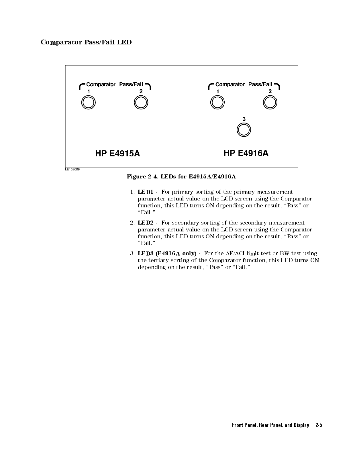
Comparator
P
ass/F
ail
LED
Figure
1.
LED1
parameter
function,
\F
2.
LED2
parameter
function,
\F
3.
LED3
the
depending
2-4.
ail."
ail."
tertiary
LEDs
-
F
or
primary
actual
this
-
F
or
secondary
actual
this
(E4916A
sorting
on the
for
E4915A/E4916A
sorting
value
on
LED
turns
sorting
value
on
LED
turns
only) -
For
of the
result, \P
of
the
primary
the
LCD
ON
depending
the
ON
depending
the
of
the
LCD
1F/1CI
screen
screen
using
on
the result,
secondary
using
on
the
limit
Comparator function,
ass" or
\Fail."
measurement
the
Comparator
\Pass"
measurement
the
Comparator
result,
test
or
this
\P
BW
LED
ass"
test
turns
or
or
using
ON
Front Panel, Rear Panel, and Display 2-5

Rear P
anel
Figure
Figure 2-6. Rear P
1.
2-5.
Rear
P
anel
(E4915A)
anel (E4916A)
Handler Interface connector-
Connects to an external handler
.
2-6 Front Panel, Rear Panel, and Display
2.
EXT REF (External Reference) terminal -
reference signal.
3.
EXT Trigger terminal -
4.
GPIB Interface connector -
that controls the E4915A/E4916A via GPIB.
5.
Power Cable Receptacle with Fuse Holder -
Accepts an external trigger signal.
Connects to an external controller
Accepts an external
Power cord socket.
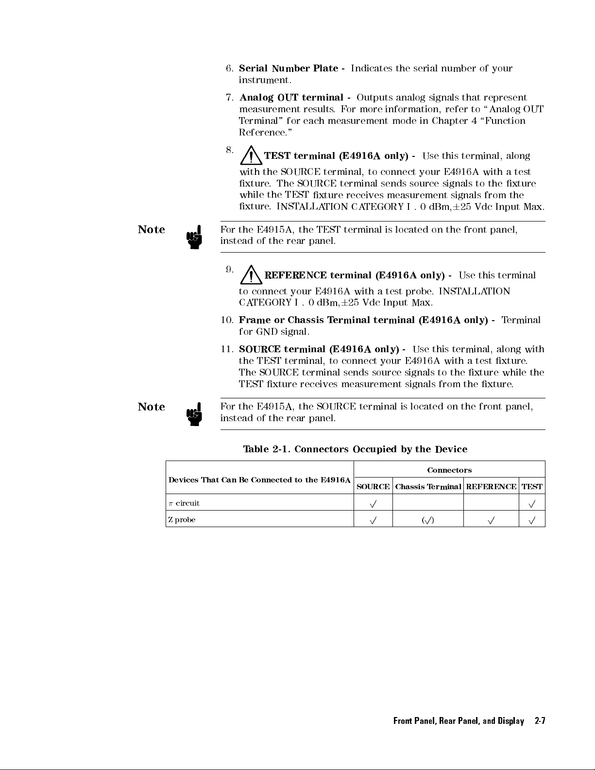
6.
Serial
Number Plate
instrument.
7.
Analog
OUT terminal
measurement results
Terminal"
for each
Reference."
-
.F
or more
-
Indicates
Outputs
the serial
analog
information,
measurement mode
signals
in
Chapter
number of
that
refer
to
4
\Function
your
represent
\Analog
OUT
Note
Note
8.
with
xture
while
xture
F
or
the
instead
9.
to
connect
CA
TEGORY
10.
Frame
for
11.
SOURCE
the TEST
The SOURCE
TEST
F
or
the
instead
TEST terminal
the SOURCE
. The
SOURCE terminal
the
TEST
.
INST
ALLA
E4915A,
of
the
rear
the
panel.
REFERENCE
your
I
.
0 dBm,
or
Chassis
GND
signal.
terminal
terminal,
terminal
xture receives
E4915A, the
of
the
rear panel.
(E4916A only)
terminal, to
xture
receives
TION
TEST
terminal
terminal
E4916A
6
25
T
erminal
(E4916A
to
connect
sends
measurement
SOURCE
connect
sends
measurement
CA
TEGORY
is
located
I
(E4916A
with
a
test
probe
Vdc Input
terminal (E4916A
only)
-
your
E4916A
source
signals
signals
terminal
is
-
Use
your
source
.
0
dBm,
on
only) -
.
Max.
Use this
located
this terminal,
E4916A
signals
signals
6
the
INST
to
25
Vdc
front
Use
ALLA
with
from
this
TION
only) -
terminal, along
with
a
test
to
the
xture
from
the
xture
on
the
front
along
a
the
xture
Input
panel,
terminal
T
erminal
xture
while
panel,
test
the
Max.
with
.
the
.
Devices
circuit
Z
probe
That Can
T
able
2-1.
Be Connected
Connectors
to
the
E4916A
Occupied
by
the
Device
Connectors
SOURCE Chassis
T
erminal
REFERENCE TEST
p p
p
(p)
p p
Front Panel, Rear Panel, and Display 2-7

K
ey
Reference
Function
4
Freq
4
(blue)
4
Level
4
(blue)
4
Meas Time
4
(blue)
4
Nominal
4
(blue)
4
CL
4
(blue)
4
Trig
4
(blue)
4
Select
4
Select
Setting K
5
5
+
4
Freq
5
5
+
4
Level
5
5
+
4
Meas
5
CI
5
+
4
Nominal
5
Value
5
+
4
CL
5
5+4
Trig (Trigger Mode)
5
(upper) Press to select the upper soft key
5
(lower) Press to
K
ey
(Xtl)
(Spurious)
Time
V
alue
eys
CI
(Flt)
5
(LCR)
(EM)
5
Figure
T
able
Press
Press
Press
5
Press
Press
5
Press
Press
5
Press to
Press
Press
Manual trigger
5
Press to set
2-7.
Function
2-2.
Sammary:
to
enter
the
nominal
to
select
Crystal
to
enter
the
power level.
to
select
Spurious
to
set
the
measurement
to
select
LCR
to enter
to
to
the nominal
select
Evaporation
enter
the
select Filter
target
the trigger mode
select the lower soft key
Resonator
measurement
measurement
Setting
Function
Function
frequency
measurement
measurement
time
mode
CI value
Monitor
CL
value
.
.
.
K
ey
Setting
.
mode
.
.
.
mode
mode
Block
.
(EM
(Flt
mode).
K
ey Block
mode
(Xtl
mode).
mode).
Applicable
Model
E4915A E4916A
p p
p p
p
p p
p p
p
p
option
010
p p
p
p p
p p
p p
p p
2-8 Front Panel, Rear Panel, and Display

Unit
Entry K
eys
4
m/k
4
(blue)
4
n/ppm
4
4
(blue)
4p5
4
(blue)
Data
5
5
+
5
5
/M
5
+
5
+
Entry K
4
4
4
K
m/k
/M
p
T
able
ey
(Comprtr)
(Equiv
(1
Mode)
eys
Figure
2-3.
5
Ckt)
5
2-8.
Unit
Summary:
Press
to
enter
Press
to
access
Press
to
enter
Press
to
enter
5
Press
to
turn
Press
to
enter
Press
to
turn
Entry
Unit
the
the
the
the
ON/OFF
the
ON/OFF
K
ey
Blocks
Entry
Function
unit.
Comparator
unit.
unit.
the
Equivalent
unit.
1
mode
K
ey
Blocks
setup menu.
.
Circuit
function.
Figure 2-9. Data Entry Key Block
Front Panel, Rear Panel, and Display 2-9

T
able 2-4.
Summary: Data
Entry
K
ey
Block
4
(blue)
4
(blue)
4
(blue)
4
(blue)
4
(blue)
4
(blue)
4
(blue)
4
(blue)
4
(blue)
4
(blue)
4
(blue)
4
(blue)
4
(blue)
4
Rcl
4
(blue)
4
BkSp
4
(blue)
4
(blue)
Applicable
K
ey
(Open)
5
5
+
4
7
Fixture
compensation
key
Function
for
the
E4915A E4916A
open compensation
Model
p
measurement.
(Short)
5
5
+
4
8
Fixture
compensation
key
for
the
short
compensation
p
measurement.
9
(Load)
5
5
+
4
Fixture
compensation
key
for
the
load
compensation
p
measurement.
(Open)
(Short)
(Load)
(Status)
(Mem
(Thru)
5
.
(Reset)
(System)
5
5
5
5
5
Buf)
5
5
5
5
5
+
4
4
5
+
4
5
5
+
4
6
5
+
4
1
5
+
4
2
5
+
4
3
5
+
4
0
5
+
4
5
+
4
0
5
+
4
Lcl
5
(Save)
5
5
+
4
Rcl
5
5
+
4
BkSp
(Entry O)
5
+
4
Enter
(x1)
5
Calibration
Calibration
Calibration
Press
Press
Calibration
Press
Press
Press
Normally
key
throughout
Remote
key
instead
switch
Press
Press
Backspace key
5
Press
Press
key
key for
key
to
turn
to access
key
to
turn ON
to reset
to
access
serves
mode
of
the
instrument
to
recall
to
save
to
turn
to
enter
for
the
the
for
the
ON/OFF
the Memory
for
the
the Key
the
instrument.
the
System
as
the
this
manual).
,
however
the
shift
previously
the
current
.
OFF
entry
a
value
open
calibration
short
calibration
load
calibration
status
display
Buer
thru
calbration
Lock function.
menu.
shift
key
When
,
the
4
(blue)
key
.
The
to
Local
saved
instrument
mode
.
with
no
unit.
.
function.
measurement.
(referred
the
5
key
5
key
4
Lcl
mode
.
instrument
settings
measurement.
measurement.
measurement.
to
as the
instrument
serves
as
the
allows
you
settings
.
.
4
(blue)
is
in
4
to
Lcl
5
5
p p
p p
p p
p p
p p
p
p p
p p
p p
p p
p p
p p
p p
p p
p p
2-10 Front Panel, Rear Panel, and Display

3
Commands
Function
Assigned to
Available
K
eys
The
E4915A/E4916A has
panel.
functions
On
the other
mode
provides
is
called the
This
functions/parameters
via Hard
These physical
.
hand, functions
are accessible
access to
soft
chapter
contains
and Soft
anumber
keys,
called
of physical
hard
specic to
via the
LCD on
the
mode-specic functions
key
.
a
series
of tables
are
assigned
to
specic
keys
each
front
that
K
or
show
eys
keys
on
its
,
are
assigned
measurement
panel.
The
parameters
what
hard
or
soft
front
common
or
setup
facility
via
the
keys
.
that
LCD
Commands Available via Hard and Soft Keys 3-1

Hard K
Note
eys
The
term
panel.
two
key
function
The
its
Each hard
functions,
in combination
is accessible
following table
non-shift state
F
or
numeric
is
available
the
4
(blue)
Some
functions
\Applicable
hard
5
key
key
key has
you can
and in
keys
when
.
are
Model"
refers
to physical
one or
access the
with the
when the
shows the
its shift
,
this
table
the
numeric
available
column.
keys provided
two functions
second function
5
(blue)
key; in
4
key is
functions
state
shows
key
only
only
is
with the
other words
in the
assigned
.
the second
pressed
on the
assigned. If
by pressing
,the
shifted state
to
.
each
function, which
in
combination with
E4916A. Refer
front
a key
second
hard
that
key
to the
has
in
Note
The
4
(blue)
5
instrument
the
switch
F
or
5
4
key
Lcl
the
the conventions
\Conventions
key
normally
is
in
Remote mode
instead
instrument
and the
and
Syntax" in
of
serves
the
to
Local
as
the
, however
shift key
mode
syntax of
Chapter 5.
shift
key.
When the
,the
4
(blue)
5
. The
key
4
Lcl
.
GPIB commands
5
key
allows
,refer
serves
you
to
as
to
3-2 Commands Available via Hard and Soft Keys

T
able 3-1.
Functions Assigned
to
Hard
K
eys
4
5
Trig
4
5
+
(blue)
4
5
Freq
4
5
+
(blue)
4
Meas
Prmtr
4
5
+
(blue)
4
5
Level
4
5
+
(blue)
4
Nominal CI
4
5+4
(blue)
Hard
K
ey
4
Trig
(Trigger Mode)
(Xtl)
5
4
Freq
5
4
Meas
Prmtr
(DLD)
4
Level (Spurious)
5
Nominal CI (EM)
Function Associated
Manual trigger \Trigger
5
Press
to
set
the
mode
.:
{Int|Man|Ext}
Press
to
nominal frequency
Press
to
Resonator
Mode
(Xtl
Press to
trigger
enter
the
.
select Crystal
Measurement
mode).
enter
a
measurement
5
5
parameter
Press
Level
measurement
(DLD
Press
power
Press
measurement
.
to
select
Drive
Dependency
mode
mode).
to
enter
the
level.
to
select
Spurious
mode.
Press to enter the
nominal CI value
5
Press to select
.
Evaporation Monitor
mode (EM mode).
in
Chapter
Function
"
Chapter
\Trigger
Function
"
Chapter 4
\Measurement
Modes" in
Chapter
\Crystal
Resonator
Measurement
Mode (Xtl
0
common
Mode)
between
E4915A
E4916A
and
"
Chapter
\Measurement
Modes"
Chapter
\Drive
Level
Dependency
Measurement
Mode
(DLD
Mode)"
Chapter
\Measurement
Modes"
Chapter
\Crystal
Resonator
Measurement
Mode
(Xtl
Mode)
0
common
between
E4915A
and
E4916A"in
Chapter 4
\Measurement
Modes" in
Chapter 4
\Evaporation
Monitor Mode
(EM Mode)" in
Chapter 4
T
4
4
the
in
4
in
4
in
4
in
4
the
opic
4
in
in
GPIB
Command
TRIGIMMediate
TRIGSOURce
f
INT
ernal
j
MANual
EXTernal
NOMFreq
MEASFunction
MEASPARA
f
MEASFunction
POWEr
MEASFunction
NOMCIt<
FR
j
BUS
t
<
value
t
t
j
FA
j
FS
j
FL
t
t
<
value
t
value
MEASFunctiontEm
E4915A E4916A
t
j
g
>
Xtal
g
Dld
>
Spur
>
Applicable
Model
p p
p p
p p
p p
p p
p
p
p p
p p
p
Commands Available via Hard and Soft Keys 3-3

T
able 3-1.
Functions Assigned
to
Hard
K
eys
(continued)
4
Meas
4
(blue)
4
CL
4
(blue)
4
Select
4
Select
4
m/k
4
(blue)
4
/M
4
(blue)
4*)5
4
(
+
4
n/ppm
4p5
4
(blue)
V
5
5
5
alue
5
5
5
5
5
Time
+
+
5
5
+
+
5
+
Hard
5
4
Meas
Time
5
4
CL
V
alue
(upper)
(lower)
4
m/k
(Comprtr)
4
/M
(Equiv
4
p(1Mode)
Key
(LCR)
(Flt)
5
5
Ckt)
Function Associated
in Chapter
Topic
4
GPIB
Command
Applicable
Model
E4915A E4916A
>
g
p p
p
p p
p
p p
p p
p p
p p
p p
p p
p p
p p
p p
p p
p p
in
4
4
in
4
4
in
4
in
4
MEASTime
t
MEASFunction
CL
TGT
t
<
MEASFunction
EQUCkt
f
DEV4
j
DEV6
<
value
t
value
t
t
j
OFF
Lcr
>
Filter
Press
to
set
measurement
the
time
.
\Measurement
Modes"
Chapter
5
Press
to select
LCR
measurement mode
.
\LCR
Measurement
Mode
"
in
Chapter
Press
target
to
enter
CL value
the
.
\Measurement
Modes"
Chapter
Press
to
select
measurement
Filter
mode
(Flt
mode).
Press
to
select
the
upper
soft key
.
Press
to
select
lower
soft
Press
to
5
Press
to
Comparator
key
enter
access
setup
.
the
the
unit.
the
menu.
Press
to
enter
the
unit.
5
Press
to
turn
ON/OFF
the
Equivalent
Circuit
function.
Press
to
move
to
the
upper
or right-hand
key/display
Press
to move
left-hand
key/display
Press
to enter
position.
or
position.
to the
lower
the
soft
soft
unit.
\Filter
Measurement
Mode
(Flt
Mode)"
in
Chapter
\Comparator
Function
Chapter
\Measurement
Modes"
Chapter
"
Press to enter the unit.
Press
to turn ON/OFF
delta mode.
\Delta
Chapter 4
Mode"in
DL
TModetfPRIjSECg,
f
OFFjDEV
PCNTjPPM
j
g
3-4 Commands Available via Hard and Soft Keys
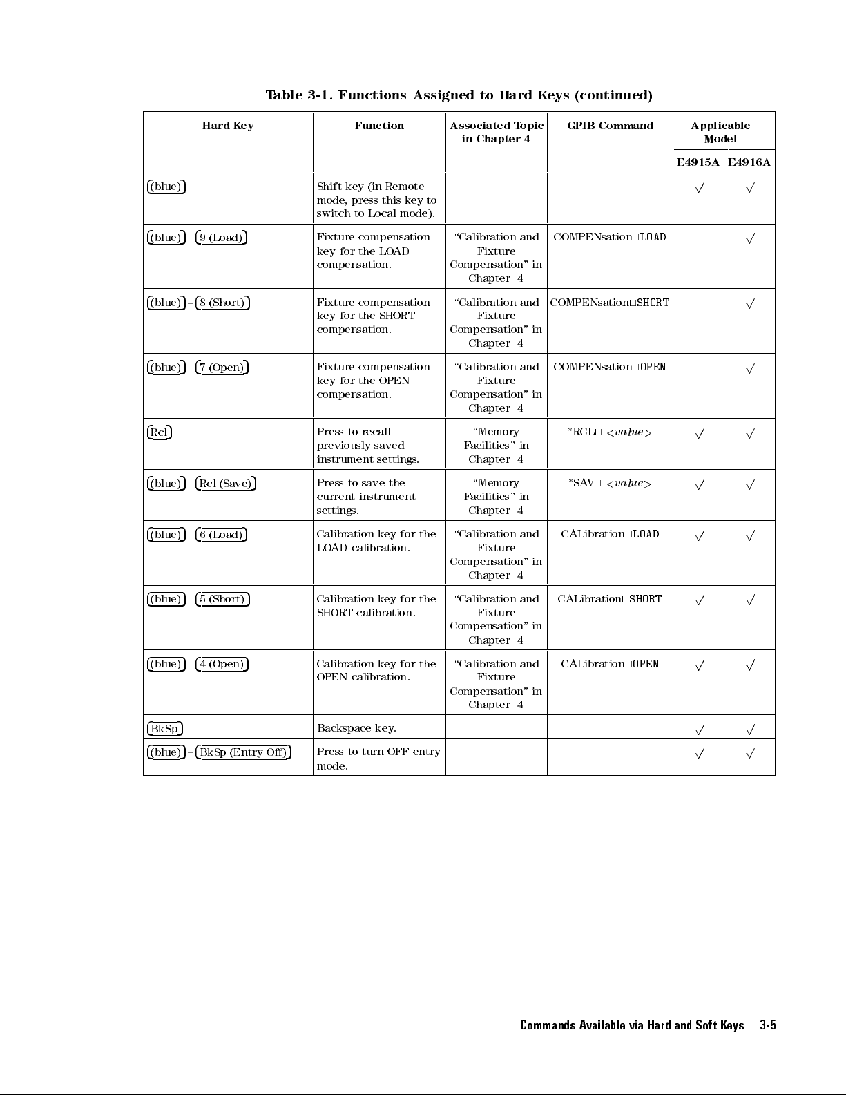
T
able 3-1.
Functions Assigned
to
Hard
K
eys
(continued)
4
(blue)
4
(blue)
4
(blue)
4
(blue)
4
Rcl
4
(blue)
4
(blue)
4
(blue)
4
(blue)
4
BkSp
4
(blue)
5
5
5
5
5
5
5
5
5
5
5+4
Hard
+
4
9
(Load)
+
4
8
(Short)
+
4
7 (Open)
+
4
Rcl
(Save)
+
4
6
(Load)
+
4
5
(Short)
+
4
4
(Open)
BkSp (Entry
Key
5
5
Function Associated
in Chapter
Topic
4
GPIB
Command
Applicable
Model
E4915A E4916A
Shift
key
(in
Remote
mode
,
press
switch
to
Local
Fixture
compensation
key for
the
LO
compensation.
this key
5
Fixture
key
for the
compensation
SHORT
compensation.
5
Fixture
key
for
compensation
the
OPEN
compensation.
mode).
AD
to
\Calibration
Compensation
\Calibration
Compensation
\Calibration
Compensation
Fixture
Chapter
Fixture
Chapter
Fixture
and
"
4
and
"
4
and
"
in
in
in
COMPENsation
COMPENsation
COMPENsation
t
LOAD
t
SHORT
t
OPEN
p p
p
p
p
Chapter 4
Press
to recall
previously saved
instrument
5
Press
current
settings
Calibration
LO
AD
5
Calibration key
SHORT
settings
to
save
the
instrument
.
key
calibration.
calibration.
.
for
the
for the
\Memory
Facilities"
Chapter
in
4
\Memory
F
acilities"
Chapter
\Calibration
in
4
and
Fixture
Compensation
Chapter
4
\Calibration and
Fixture
Compensation
"
"
in
in
*RCL
t
<
*SA
V
t
<
CALibration
CALibration
value
value
t
t
SHORT
>
>
LOAD
p p
p p
p p
p p
Chapter 4
5
O)
Calibration
OPEN calibration.
Backspace
5
Press to turn OFF entry
key
key.
for
the
Compensation
\Calibration
Fixture
Chapter
and
"
4
in
CALibration
t
OPEN
p p
p p
p p
mode.
Commands Available via Hard and Soft Keys 3-5

T
able 3-1.
Functions Assigned
to
Hard
K
eys
(continued)
4
(blue)
4
(blue)
4
(blue)
4
Enter
4
(blue)
4
(blue)
4
(blue)
4
(blue)
5
+
5
+
5
+
5
5
+
5
+
5
+
5
+
Hard
4
3
(Thru)
4
2 (Mem
4
1
(Status)
4
Enter
4
0
(System)
4
. (Reset)
4
0 (Key
Key
5
Buf)
(x1)
Lock)
Function Associated
in Chapter
Topic
4
GPIB
Command
Applicable
Model
E4915A E4916A
Calibration
thru
5
Press to
Memory
state
key
.
access
Buer
for
the
function.
5
5
5
5
Press
status
Press
value
Press
with
Press
System
Press
to
turn
display.
to
put
into
to
enter
no
unit.
to
access
menu.
to
reset
ON/OFF
the
eect.
a
the
entered
value
the
instrument.
5
Press
Key
to
Lock
turn
ON
function.
the
the
\Calibration
Fixture
Compensation
Chapter
\Memory
F
acilities"
Chapter
\Reset
Function
in
Chapter
\Key
Lock"
Chapter
and
"
4
in
4
4
in
4
in
"
THRUCAL
MESTA
f
OFF
j
ON
DISPST
f
OFF
j
ON
PRESet
KLOCK
f
OFF
j
ON
T
e
t
j
0
j
1
g
A
Tus
t
j
0
j
1
g
p p
p p
p p
p p
p p
p p
t
j
0
j
1
g
p p
p
Soft
K
eys
When
the
to
consists
rightmost
the
4
through
4
access
This
describes
LCD
functions
right
5
Select
5
key to
*
)
section
you
are
screen
or
of
two
area.
of
the
key
to
alternative
access
the next
contains
the
working
in
a
particular
presents you
parameters specic
lines,
and usually
Two
physical
LCD
screen.
select
the
rst
or
pairs
of
soft
the
previous
pair
of
soft
keys
a
series
soft
keys
specic
with
soft
to
shows
5
4
Select
Y
ou
can
second
keys
pair
.
of
subsections
to
a
measurement
keys
that
that
mode
a
pair
keys
are
press
either
soft
key
in
a
cyclic
of
soft
keys
each
particular
or
setup
provide
.
The
LCD
of
soft
keys
arranged
.
Y
the
ou
vertically
upper
can
fashion:
,
or
the
of
which
measurement
mode
access
screen
in
the
or
lower
navigate
Press
5
4
(
+
briey
or setup
,
to
the
key to
mode. Note that soft keys are displayed in the same order as listed in
each subsection.
To begin with,
shows how to access each
you may want to refer to the following table that
of the measurement or settings modes
covered in this section.
3-6 Commands Available via Hard and Soft Keys
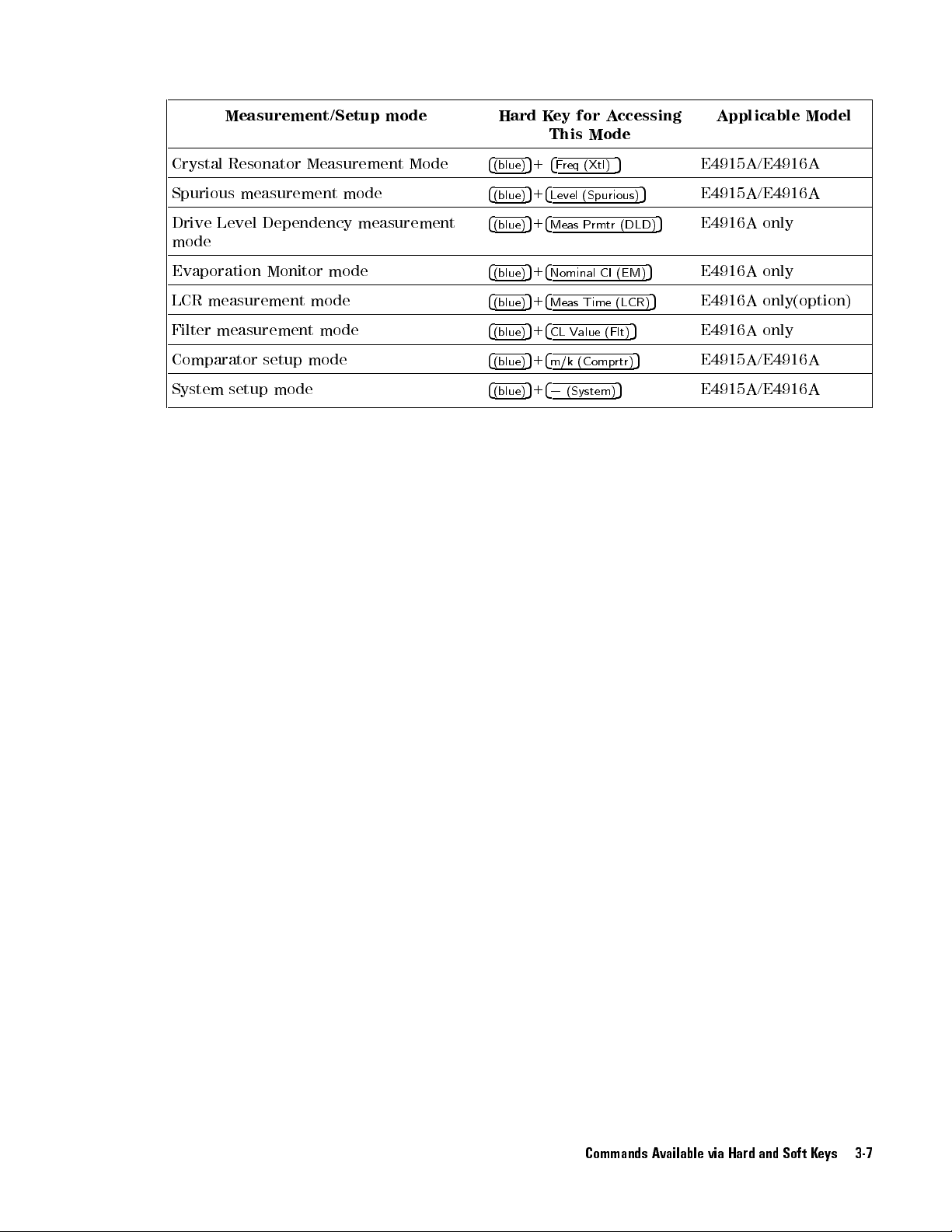
Measurement/Setup
mode
Hard
K
ey
This
for
Mode
A
ccessing
Applicable
Model
Crystal
Resonator Measurement
Spurious measurement
Drive
Level
Dependency
mode
Evaporation
LCR measurement
Filter
measurement
Comparator
System
setup
Monitor
setup
mode
mode
mode
mode
mode
measurement
mode
Mode
4
(blue)
4
(blue)
4
(blue)
4
(blue)
4
(blue)
4
(blue)
4
(blue)
4
(blue)
5
+
4
F
req
5
+
4
Level (Spurious)
5
+
4
Meas
5
+
4
Nominal
5
+
4
Meas
5
+
4
CL
Value
5
+
4
m/k
5
+
4
0
(System)
5
(Xtl)
Prmtr (DLD)
CI
(EM)
Time
(LCR)
5
(Flt)
(Comp
rtr)
5
E4915A/E4916A
5
5
5
5
E4915A/E4916A
5
E4916A
E4916A
E4916A
E4916A
E4915A/E4916A
only
only
only(option)
only
E4915A/E4916A
Commands Available via Hard and Soft Keys 3-7

Soft
Keys
Soft
K
ey
FF
F
F
F
F
F
F
F
F
F
F
FREQ
F
F
F
F
F
F
F
F
RNG
F
F
F
F
F
FF
CI
F
F
F
F
F
F
F
F
ALC
F
F
F
F
F
F
F
F
LVL
F
F
F
F
F
F
F
F
UNIT
F
F
F
F
F
F
F
F
TIME
F
F
F
F
FF
FF
HI
F
F
F
F
F
F
FF
EQUC
F
F
F
F
F
F
F
F
DspQ
F
F
F
F
F
F
F
F
TGT
F
F
F
F
F
F
F
F
PHAS
F
F
F
F
F
F
F
1F
F
F
F
F
F
F
F
F
RefF
F
F
F
F
F
FF
F
1CI
F
F
F
F
F
F
FF
RefZ
F
FF
FF
FF
F
AGE
F
F
F
F
F
F
F
FF
Time
FF
FF
FF
F
F
PARA {Fs|Fr|Fa|FL}
F
FF
F
F
F
F
F
CKT
FFFFFFFFFFFF
CL_a
F
FFFFFFFFFF
CL_t
value
F
value
value
F
{OFF|ON}
F
value
F
F
F
F
{dBm|WATT|AMP|VOLT}
F
F
F
F
{Short|Med|Long}
F
F
F
F
Q
{OFF|ON}
F
F
F
F
{OFF|4DEV|6DEV}
F
F
F
F
{OFF|ON}
F
{Phase|Peak}
F
F
F
F
value
{OFF|DEV|PPM}
F
FF
F
{Nominal|User}
F
{OFF|DEV|%}
FF
F
F
{Nominal|User}
F
{OFF|ON}
FF
F
value
F
F
F
F
F
{PI|PROBE|BRIDGE|NONE}
value
F
value
P
arameter
Crystal
and
Resonator Measurement
Functions
Nominal
Search
Nominal
ALC
P
ower
P
ower
Measuring
High
Equivalent
ON/OFF
Show/hide
Search
T
arget
Delta
Reference
mode
Delta
Reference
mode
Aging
Aging
Measurement P
Measurement
Actual CL value
Target CL value
T
able 3-2.
Specic
Mode
Function
frequency
range
[ppm]
impedance
MODE
ON/OFF
level
[W
,A,V
unit
time
Q
mode
ON/OFF
Circuit
the
Q
target
specication
phase
mode
[Hz]
mode for
[]
mode ON/OFF
interval
]
[
for
frequency
impedance for
arameter
circuit
Mode (Xtl
to
Crystal
[Hz]
[] NOMCI
,dBm]
Analysis
parameter
frequency DL
for
crystal
Resonator
mode
Delta
impedance
Delta
NOMFreq
SRCHRange
ALC
POWEr
[mW
POWEr
[mW
MEASTime
MEASTime
EQUCkt
DSPQ
SRCHTGT
TGTPhase
f
DL
DL
f
DL
A
AGINGTIME
MEASP
CIRcuit
PICKTtype
PI41902A
CLACTt<
CLTGTt<
Measurement
t
<
tf
OFF
t
<
j
UW
j
t
<
j
UW
j
tf
tf
OFF
TMode
OFF
j
DEV
TREF
tf
TMode
OFF
j
DEV
TREF
tf
GING
tf
ARA
tf
t
<
t
value
j
ON
value
NW
value
NW
t
t
DEV4
tf
t
<
tf
j
PCNT
PRI
tf
j
PCNT
SEC
OFF
tf
PI
tf
g
value
value
GPIB
SEC
SEC
Mode)
Command
value
>
<
value
>
j
0
j
1
>
j
W
j
MA
>
j
W
j
MA
<
value
<
value
j
DEV6
j
ON
j
0
j
PHase
value
g
,
g
g
,
<
g
,
g
g
,
<
j
ON
j
0
t
<
value
FR
j
F
j
PRObe
PI41900A
>
>
>
g
j
UA
j
UA
>
>
1
g
j
PEak
>
value
value
j
1
g
>
A
j
FS
j
BRIdge
j
A
j
MV
j
A
j
MV
j
OFF
g
g
>
>
j
FL
g
g
j
PI41901A
j
j
UV
UV
j
j
j
V
V
j
DBM]
j
DBM]
3-8 Commands Available via Hard and Soft Keys

Soft
F
F
FF
FF
FF
FF
CENT
F
F
F
F
F
F
F
F
F
RNG
F
F
F
F
F
F
F
F
FF
DispSP
F
F
F
F
F
F
F
F
FF
#Spur
F
F
F
F
F
F
F
F
F
TGT
F
FF
FF
F
F
F
F
F
PHAS
K
ey
FF
FF
FF
FF
FF
FF
F
F
Soft
Keys
P
arameter
value
value
{Nth|Worst}
value
{Phase|Peak}
value
Spurious
and
Functions
Measurement Mode
T
able 3-3.
Specic
to
Spurious
Function
Center frequency
Search
range
Spurious
(Nth or
Number
point
worst spurious)
of
[Hz] SPCENT
[ppm]
to
be
displayed
spurious
points
search for
Search
target
specication
T
arget
phase
]
[
Measurement
to
SPRANGe
SPDISP
tf
SPNUM
t
SPTGT
tf
SPPHAse
er
t
t
W
<
PHase
t
GPIB
<
value
<
value
orst
value
<
value
Mode
Command
>
>
[
f
j
Nth
g
>
j
PEak
>
[,
g
Hz
<
j
Ppm
value
g
]
>
]
Commands Available via Hard and Soft Keys 3-9

Soft
Keys
Soft
K
ey
FF
F
F
F
F
F
F
F
F
F
F
FREQ
F
F
F
F
F
F
F
F
RNG
F
F
F
F
F
FF
CI
F
F
F
F
F
F
F
F
SWEP
F
F
F
F
F
F
F
F
TIME
F
F
F
F
F
F
FF
HI
F
F
F
F
F
F
F
FF
MIN
F
F
F
F
F
F
F
F
MAX
F
F
F
F
F
F
F
F
STD
F
F
FF
FF
F
F
UNIT
F
F
FF
F
F
F
F
WAIT
F
F
F
F
F
F
F
F
StartP
F
FF
F
F
F
F
F
ABORT
F
F
F
F
F
FF
FF
ALC
F
F
F
F
F
F
F
1F
F
F
F
F
F
F
F
F
RefF
F
FF
F
F
F
F
F
1CI
FF
F
F
F
F
F
F
RefZ
F
FF
FF
FF
FF
TGT
FFFFFFFFF
PHAS
FFFFFFFFFFFF
PARA {Fs|Fr}
F
FFFFF
FFF
CKT {PI|PROBE|BRIDGE}
F
FFFFFFFFFFF
TRKG {ON|OFF}
value
F
value
value
F
F
F
F
{Up|UpDown|UpMin|List}
F
F
F
F
{Short|Med|Long}
FF
FF
Q
{OFF|ON}
value
F
value
F
value
F
F
F
F
{dBm|WATT|AMP|VOLT}
F
F
F
F
value
F
F
F
F
F
F
F
F
value
F
F
F
F
F
F
{OFF|ON}
{OFF|ON}
{OFF|DEV|PPM}
F
F
F
F
{Nom|User|Start}
F
{OFF|DEV|%}
F
F
F
F
{Nom|User|Start}
{Phase|Peak}
FFF
value
P
arameter
Drive
and
Level Dependency
T
able 3-4.
Functions
Nominal
Search
Nominal
Sweep
Measuring
High
Minimum
Maximum
Reference
P
ower
W
ait
Sweep
Whether
measurement
failed
ALC MODE
Delta
Reference
mode
Delta
Reference
[]
Search
Target phase [
Type of search frequency
Measurement circuit
Phase tracking ON/OFF
Specic
Measurement
Function
frequency
range
[Hz/ppm]
CI
[] NOMCI
type
time
Q
mode ON/OFF
drive
level
drive
level
drive
level
unit
time
after
energization
start
point
to
continue
when
ON/OFF ALC
mode
for
frequency
frequency
[Hz]
mode
for
CI
value
CI
value
target
specication
] TGTPhaset<
Measurement Mode
to
Drive
Mode
[Hz]
[W,A,V
[W
,A,V
or
abort
tracking has
for
Delta
for
Delta
Level
NOMFreq
SRCHRange
PTSWPType
f
UPDOWN
MEASTime
MEASTime
,dBm] PTMINP
,dBm]
PTMAXP
PTSTDP
PTMINP
W
j
MA
PTMAXP
W
j
MA
PTSTDP
W
j
MA
PTW
AIT
PTST
PT
ABORT
tf
DL
TMode
DL
TREF
DL
TMode
DL
mode
TREF
SRCHTGT
MEASPARAtfFRjFS
CIRcuittfPIjPRObejBRIdge
PICKTtypetfPI41900AjPI41901A
PI41902A
PTRACKtfONjOFFj0j1
Dependency
GPIB
t
<
value
t
<
value
t
<
value
>
t
j
UP
j
UPMIN
t
<
value
t
<
value
ower
t
<
value
ower
t
<
value
ower
t
<
value
ower
t
<
j
A
ower
j
A
j
A
<
value
oint
tf
j
ON
t
PRI
PRI,
t
SEC
SEC,
tf
g
j
MV
t
<
j
MV
t
<
j
MV
t
OFF
j
0
tf
<
tf
<
PHase
value
value
j
UV
value
j
UV
value
j
UV
>
<
value
j
ON
j
1
OFF
value
OFF
value
j
UA
j
U
A
ower
j
U
A
t
ARTP
OFF
t
t
(DLD
Command
>
>
>
>
j
V
j
V
j
V
j
0
g
j
PEak
>
g
j
LIST
>
>
>
>
j
DBM]
>
j
DBM]
>
j
DBM]
>
j
1
j
DEV
>
j
DEV
>
g
Mode)
[mW
[mW
[mW
g
j
g
g
j
UW
j
UW
j
UW
PPM
j
PCNT
g
g
j
j
NW
j
NW
NW
g
j
j
j
j
3-10 Commands Available via Hard and Soft Keys
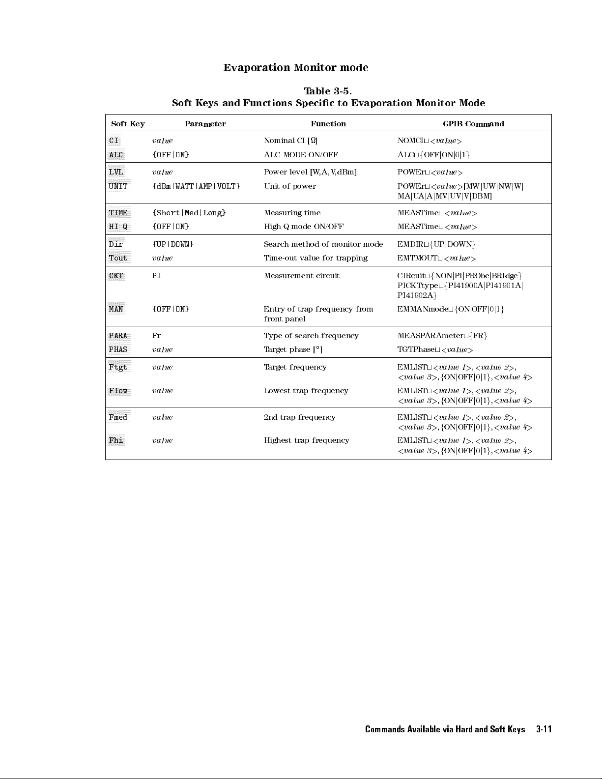
Soft
F
F
FF
FF
CI
F
F
F
F
F
ALC
F
F
F
F
F
LVL
F
FF
FF
UNIT
FF
FF
F
TIME
F
F
F
F
F
HI
F
F
F
F
F
Dir
F
F
F
F
F
Tout
F
F
F
F
F
CKT
F
F
F
F
F
MAN
F
F
F
F
F
PARA
F
F
F
F
F
PHAS
F
F
F
F
F
Ftgt
F
FF
F
F
Flow
F
F
F
F
F
Fmed
FF
F
F
F
Fhi
Evaporation
Soft
Keys
and
Functions
K
ey
F
F
F
F
F
F
F
F
F
FF
F
F
F
F
F
F
F
F
F
F
Q
F
F
F
F
F
F
F
F
F
F
F
F
F
F
F
F
F
F
F
F
F
FF
FF
F
F
F
F
F
F
F
F
F
F
FF
F
F
F
F
value
{OFF|ON}
value
F
F
F
{dBm|WATT|AMP|VOLT}
F
F
F
{Short|Med|Long}
FF
F
{OFF|ON}
{UP|DOWN}
F
F
F
value
PI
{OFF|ON}
FF
F
Fr
F
F
value
FF
F
value
F
F
F
value
F
F
F
value
value
P
arameter
Nominal CI
ALC
P
Unit
Measuring
High
Search
Time-out
Measurement
Entry
front
Type
T
T
Lowest
2nd
Highest
Monitor mode
T
Specic
[] NOMCI
MODE
ON/OFF
ower
level
of power
time
Q
mode
method
value
of
trap
panel
of
search
arget
phase [
arget
frequency
trap
trap
frequency EMLIST
trap
able 3-5.
to
Evaporation
Function
[W
,A,V
,dBm] POWEr
ON/OFF
of
monitor
for
circuit
frequency
frequency
]
frequency
frequency
mode
trapping
from
Monitor
t
<
value
ALC
tf
OFF
j
t
<
value
POWEr
t
<
j
U
A
j
A
tf
tf
ARAmeter
t
3
t
3
t
3
t
3
value
j
MV
UP
t
NON
g
t
<
>
,
<
>
,
<
>
,
<
>
,
t
t
tf
value
f
value
f
value
f
value
f
MA
MEASTime
MEASTime
EMDIR
EMTMOUT
CIRcuit
PICKTtype
PI41902A
EMMANmode
MEASP
TGTPhase
EMLIST
<
value
EMLIST
<
value
<
value
EMLIST
<
value
Mode
GPIB
>
ON
j
0
j
>
>
j
UV
<
value
<
value
j
DOWN
<
value
j
PI
PI41900A
tf
ON
<
value
ON
j
OFF
ON
j
OFF
ON
j
OFF
ON
j
OFF
Command
1
g
[MW
j
UW
j
V
j
DBM]
>
>
g
>
j
PRObe
j
PI41901A
j
OFF
j
tf
FR
g
>
1
>
,
<
value
j
0
j
1
g
1
>
,
<
value
j
0
j
1
g
1
>
,
<
value
j
0
j
1
g
1
>
,
<
value
j
0
j
1
g
j
NW
j
BRIdge
0
j
1
g
2
,
<
value
2
,
<
value
2
,
<
value
2
,
<
value
j
W
j
g
j
>
,
4
>
>
,
4
>
>
,
4
>
>
,
4
>
Commands Available via Hard and Soft Keys 3-11

LCR
T
able 3-6.
Soft
K
ey
F
FF
FF
FF
FF
FF
F
Pri1 {Z|Y|R|G|Cs|Cp|Ls|Lp}
F
F
F
F
F
F
F
F
F
F
F
F
Sec1
F
F
F
F
F
F
FF
Pri2
F
FF
F
F
F
F
F
Sec2 {
F
F
F
F
F
F
F
F
TIME
F
F
F
F
F
F
F
F
AVG
F
F
F
F
F
F
F
F
LVL
F
F
F
F
F
F
F
F
UNIT
F
F
F
F
F
F
F
F
Vmon
F
F
F
F
F
F
F
FF
Imon
F
FF
F
F
F
F
F
1P1
F
F
FF
F
F
F
F
Ref
F
F
F
F
F
F
F
F
1S1
F
FF
F
F
F
F
F
Ref
F
F
F
F
F
F
FF
1P2
F
F
F
F
F
F
F
FF
Ref
F
F
F
F
F
F
F
F
1S2
F
FFFFFFFF
Ref
FFFFFFFFF
DGT
F
FFFF
FFFF
CKT {PI|PROBE|BRIDGE}
F
FFFFFFFFFFF
FREQ
{
z|
y|X|B|D|Q|Rs|Rp|G}
FF
FF
{Z|Y|R|G|Cs|Cp|Ls|Lp}
F
F
F
F
z|
y|X|B|D|Q|Rs|Rp|G}
F
F
F
F
{Short|Med|Long}
F
value
F
value
FF
FF
{dBm|WATT|AMP|VOLT}
F
F
F
F
{OFF|ON}
FF
F
{OFF|ON}
F
{OFF|DEV|%}
F
value
F
{OFF|DEV|%}
F
value
F
{OFF|DEV|%}
value
F
{OFF|DEV|%}
value
value
value
Soft
K
eys
P
arameter
[MHz] Measurement frequency :SOURce:FREQuency
Measurement Mode
and
Functions
Primary parameter
Secondary
Primary
Secondary
Measurement
A
P
P
V
Current
Delta
1
Reference
parameter
Delta
parameter
Reference
parameter
Delta
2
Reference
parameter
Delta
parameter 2
Reference value of secondary
parameter 2
Display digits
Measurement circuit :CIRcuittfPIjPRObejBRIdge
veraging
ower
level[W
ower
unit
oltage
mode
mode
mode
mode
parameter
monitor
monitor
Specic
Function
1 :SENS:FUNC:ON
parameter
2
parameter
time
factor
,V
,A,dBm]
ON/OFF
ON/OFF
for
primary
value
of
primary
1
for
Delta
for
secondary
1
value
of
secondary
1
for
Delta
for primary
value
of primary
2
for
Delta
for
secondary
for Delta mode
1
2
parameter
mode
mode
parameter
mode
to
LCR
Measurement
GPIB
:CALC1:FORM
f
MLIN
j
REAL
j
CP
j
:SENS:FUNC:ON
:CALC2:FORM
f
PHAS
j
IMA
G
j
D
j
Q
:SENS:FUNC:ON
:CALC3:FORM
f
MLIN
j
REAL
j
CP
j
:SENS:FUNC:ON
:CALC4:FORM
f
PHAS
j
IMAG
j
D
j
Q
:SENS:FIMP:APER
:SENS:A
:SOUR:V
[A
CALCulate6:MA
CALCulate5:MATH:ST
:CALC1:MA
f
:D
:CALC2:MA
f
:CALC2:MA
f
:D
:CALC3:MA
f
:CALC4:MA
f
:DATA: REF4,
:DISP:TEXT1:DIGf3j4j5
PICKTtypetfPI41900AjPI41901A
PI41902A
VER:COUN
OL
j
MA
j
W
j
V
DEV
j
PCNT
AT
A:
REF1,
DEV
j
PCNT
DEV
j
PCNT
A
T
A:
REF2,
DEV
j
PCNT
DEVjPCNT
g
T
<
value
j
MV
j
DBM]
TH:ST
TH:EXPR:NAME
g
<
value
TH:EXPR:NAME
g
TH:EXPR:NAME
g
<
value
TH:EXPR:NAME
g
TH:EXPR:NAME
g
<
value
f
CS
f
f
CS
f
Mode
Command
FIMP
j
F
ADM
j
LP
j
LS
FIMP
j
F
ADM
j
REAL
j
RP
FIMP
j
FADM
j
LP
j
LS
FIMP
j
F
ADM
j
REAL
j
RP
f
Short
<
value
>
AT
e
AT
e
>
>
>
g
g
g
g
g
g
g
g
g
j
Med
>
f
ON/OFF
f
ON/OFF
g
j
Long
g
g
g
j
3-12 Commands Available via Hard and Soft Keys
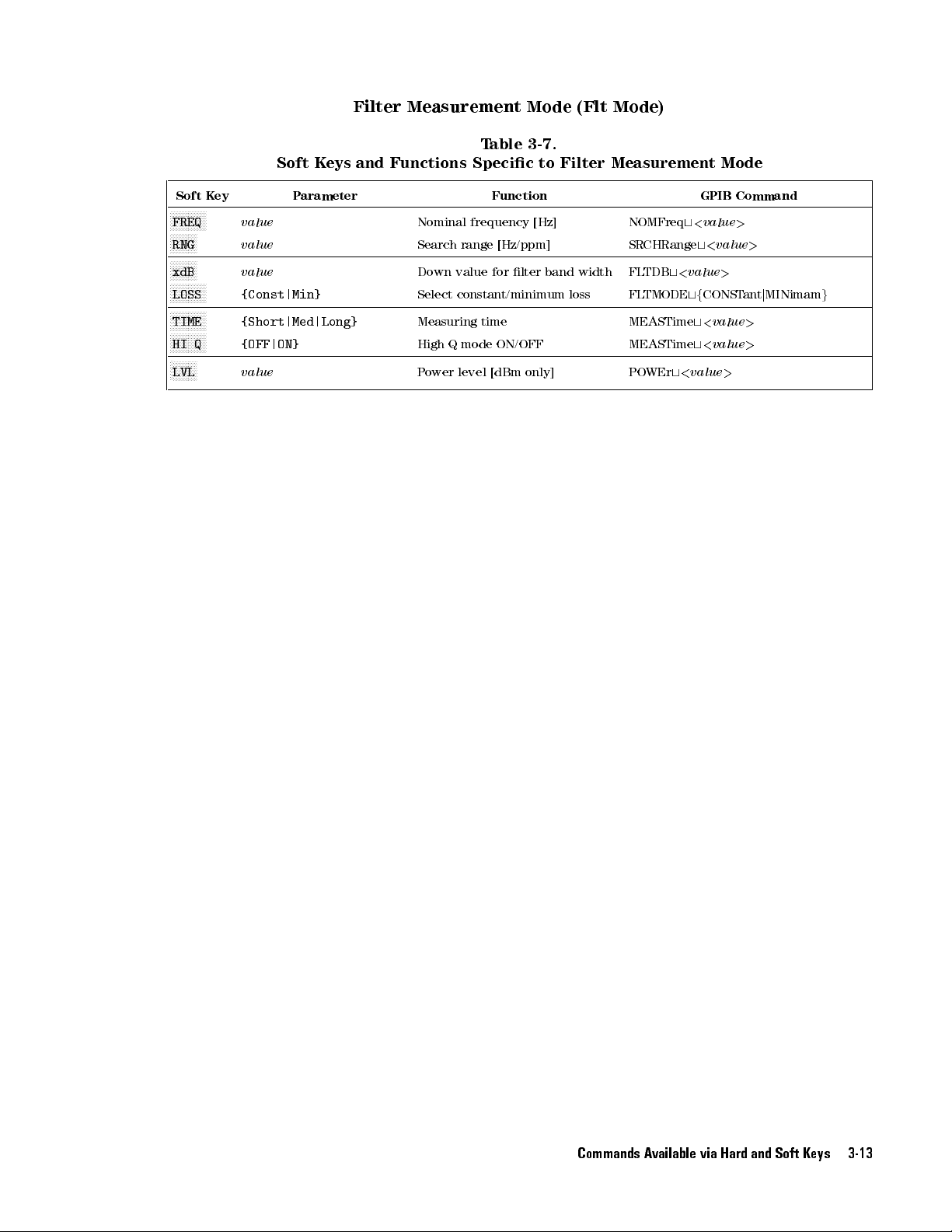
Soft
F
F
FF
FF
FREQ
F
F
F
F
F
RNG
F
F
F
F
F
xdB
F
FF
FF
LOSS
FF
F
F
F
TIME
F
F
F
F
F
HI
F
F
F
F
F
LVL
Filter
Soft
Keys
and
K
ey
FF
FF
FF
F
F
F
F
F
F
F
F
FF
F
F
F
F
F
F
FF
FF
Q
F
F
F
F
value
value
value
F
F
F
{Const|Min}
F
F
F
{Short|Med|Long}
FF
F
{OFF|ON}
value
P
arameter
Measurement Mode
T
able 3-7.
Functions
Specic
Function
Nominal frequency
Search
range
[Hz/ppm]
Down
value
for
lter
Select
constant/minimum loss
Measuring
High
P
ower
Q
time
mode
ON/OFF MEASTime
level
[dBm
only] POWEr
(Flt Mode)
to
Filter
Measurement
[Hz] NOMFreq
SRCHRange
band
width FL
TDB
FL
TMODE
t
MEASTime
t
t
<
<
GPIB
<
value
t
<
value
tf
CONST
t
<
t
<
value
Mode
Command
>
value
>
value
value
>
>
ant
>
>
j
MINimam
g
Commands Available via Hard and Soft Keys 3-13

T
able 3-8.
Soft
K
ey
F
FF
FF
FF
FF
FF
F
COMP {OFF|ON}
F
F
F
F
F
F
F
F
F
SEC
F
F
F
F
F
F
F
F
AUX
F
F
F
F
FF
FF
PRI
F
FF
FF
FF
F
NOM
F
F
F
F
FF
FF
BEEP
F
FF
FF
F
F
F
LED {Pass|Fail}
F
F
F
F
F
F
F
F
PriH
F
F
F
F
F
F
F
F
PriL
F
F
F
F
F
F
F
F
SecH
F
F
F
F
F
F
F
F
SecL
F
F
F
F
F
F
F
F
Lm1F
F
F
F
F
F
F
F
F
Lm1Z
F
F
F
F
F
F
F
F
1F_H
F
F
F
F
F
F
F
F
1Z_H
F
F
F
F
F
F
F
F
BW_H
F
F
F
F
F
F
F
F
BW_L
F
F
F
F
FF
F
F
LmBW {OFF|ON}
{OFF|ON}
F
{OFF|ON}
F
{ABS_TOL|%TOL|SEQ}
F
value
FF
F
F
{Pass|Fail}
F
F
FF
F
value
F
F
F
F
value
F
F
F
F
value
F
F
F
F
value
F
F
F
F
{OFF|ON}
F
F
F
F
{OFF|ON}
F
F
F
F
value
F
F
F
F
value
F
F
FF
value
F
F
FF
value
F
F
F
F
P
arameter
Comparator
Soft
K
eys
Setup Mode
and
Functions
Function
Comparator function
Secondary
A
UX
Sort mode
Nominal value
T
olerance
Whether to
outputting
Whether to
illuminating
Upper
sorting
Lower
sorting
Upper
sorting
Lower
sorting
1F
(for
1CI
(for
1F
(for DLD
1CI
(for
Upper
(for Flt
Lower
(for
BW
sorting
bin
ON/OFF
for primary
mode
indicate P
beep
indicate
LED
limit
value
limit
value
limit
value
limit
value
limit
test
ON/OFF
DLD
mode only)
limit
test
DLD
mode
limit
value
mode only)
limit
value
DLD
mode
limit
value
mode
limit
value
Flt
mode
limit test ON/OFF
(Xtal, DLD
Specic
ON/OFF COMPST
ON/OFF
sorting COMPPRIMode
applied to
ass or
sound.
P
ass
or
.
for
primary
for
primary
for
secondary
for
secondary
ON/OFF
only)
only)
for
BW
only)
for
only)
BW
,
to
Comparator
COMPSECondary
COMPSECA
f
ABSTOL
COMPTOLSTD
COMPBEEPCond
F
ail
by
COMPLEDCond
F
ail
by
COMPPLIMit
1
>
,
<
value
COMPPLIMit
1
>
,
<
value
COMPSLIMit
COMPSLIMit
COMPDL
COMPDL
COMPDL
COMPDL
COMPBWLim
COMPBWLim
COMPBWtfOFFjONj0j1
Flt,
AT
j
TF
TCI
TFLim
TCILim
LCR
Setup
GPIB
e
tf
OFF
tf
UX
tf
OFF
t
PCNTTOL
t
<
value
tf
tf
t
<
BIN1
2
>
t
<
BIN1
2
>
t
<
value
t
<
value
tf
OFF
tf
OFF
t
<
t
<
t
<
value
t
<
value
only)
Mode
Command
j
ON
j
0
j
1
g
OFF
j
ON
j
ON
j
0
j
SEQ
g
>
FAIL
j
P
ASS
FAIL
j
P
ASS
>
,
<
value
>
,
<
value
1
>
,
<
1
>
,
<
j
ON
j
0
j
1
g
j
ON
j
0
j
1
g
value
>
value
>
1
>
,
<
1
>
,
<
g
j
0
j
1
j
1
g
g
g
value
value
value 2
value 2
g
2
>
2
>
>
>
3-14 Commands Available via Hard and Soft Keys

T
able 3-9.
Soft
K
F
FF
FF
FF
DISP {OFF|ON}
F
FF
FF
F
CAL {Op|Sh|Ld}
F
F
F
F
F
F
COMP
F
F
FF
F
F
DelDATA
F
F
F
F
F
F
MemClear
F
F
F
F
F
F
BEEP
F
F
F
F
FF
GPIB
F
F
F
F
F
F
AnalogOut
F
F
FF
FF
Settings
F
F
F
F
F
F
Service
F
F
F
F
F
F
Self
ey
FF
FF
F
F
F
F
F
F
F
F
F
F
F
F
F
F
F
F
F
F
F
F
F
F
F
F
F
FF
FF
FF
F
F
F
F
F
F
F
FF
FF
F
F
FF
FF
F
F
F
F
F
F
F
FF
FF
F
F
F
F
F
F
F
F
F
F
F
F
F
F
F
F
F
F
F
F
F
F
F
F
F
F
F
FF
F
F
F
F
F
F
F
F
F
F
F
F
F
F
FF
F
F
F
F
F
F
Test
F
F
F
F
F
F
F
F
F
Func
F
F
F
{Op|Sh|Ld}
{NO|YES}
{OFF|ON}
1
{OFF|ON}
{dFdV|REF}
soft
eld.
F
F
F
F
{Key
RAM
{NO|YES}
to 31
key
|
|
P
opens
HNDL
FLASH}
System
Soft
K
eys
arameter
(Selecting this
value
|
CSUM
Setup Mode
and
Functions
Measurement data
Calibration standard
Fixture
value
Clears
Clears
Beep
When
never
GPIB address
31:talk
Analog
ON/OFF
Analog
entry
Service
|
Self
compensation
the
last
buer
ON/OFF
BEEPST
sound
only
mode(for
OUT
OUT
test
test
Specic
Function
data
A
T
eis
even
terminal
terminal settings
to
display ON/OFF
value
standard
in
the
buer
OFF
,the
an
error
Print
output
System
beep
occurs
out)
Setup
GPIB
DISP
tf
OFF
CALSTD
<
CALSTD
f
COMPENSTD
<
COMPENSTD
f
MEMRETEST
MEMCLEar
BEEPST
GPIB
ANLGOUT
ANLGDFDV
ANLGREF
-
-
value
R0
j
value
R0
j
t
OPEN,
>
tf
L0
g
,
<
>
L0
g
,
<
A
T
ADDRess
t
value
value
e
t
Mode
Command
j
ON
j
SHORT
>
t
OPEN,
tf
SHORT
tf
OFF
t
<
f
OFF
t
<
value
<
value
0
j
1
f
>
value
j
j
g
G0
LO
j
ON
ON
j
C0
g
,
AD
g
,
f
G0
j
C0
g
,
j
LO
AD
g
,
j
0
j
1
g
>
j
0
j
1
g
>
,
>
Commands Available via Hard and Soft Keys 3-15


4
Function
Reference
This chapter
incorporated
for
An
Purpose
Description
Applicable
with
that
LCR Meter
E4916A
How
means:
are
accessible
each
function:
overview
both
some
to
accessible
provides descriptive
into
the
E4915A/E4916A.
of
the
function
and
principle
of
parameters
models
E4915A
functions
function is
and
access
the
front
through
it
is
the
by
0
Indicates
and
E4916A
require
available
equipped
function
panel
these
two
the
front
and
information
whether
or
a
particular
only
with
Option
0
Describes
the
GPIB
means;
panel
only
.
some
or
It
presents
the
with
option
when
010).
each
Note
via
on
various
the
function
the
E4916A.
(for
your
instrument
of
the
that
not
functions
the
GPIB
following
is
example
two
all
are
.
functions
available
Note
,
the
is
access
functions
only
topics
the
Measurement
Modes
The
E4915A
modes
Crystal
and
in common:
Resonator
the E4916A
measurement
provide the
mode
following
(also
referred
two
measurement
to
as
\Xtl
mode").
Spurious
In
addition to
measurement mode
the above
two measurement
modes
,
the
E4916A
provides the following four extended measurement modes:
Drive Level Dependency measurement mode (also referred to as
\DLD mode")
Evaporation Monitor mode (also referred to as \EM mode" or \Trap
mode")
Filter measurement mode (also referred to
as \Flt mode")
LCR measurement mode (requires Option 001/010)
This section presents the following topics for each measurement
mode:
Purpose and principle
Parameters and their settings
Measurement functions available in the measurement mode
Function Reference 4-1

Output
of measurement
results
4-2 Function Reference
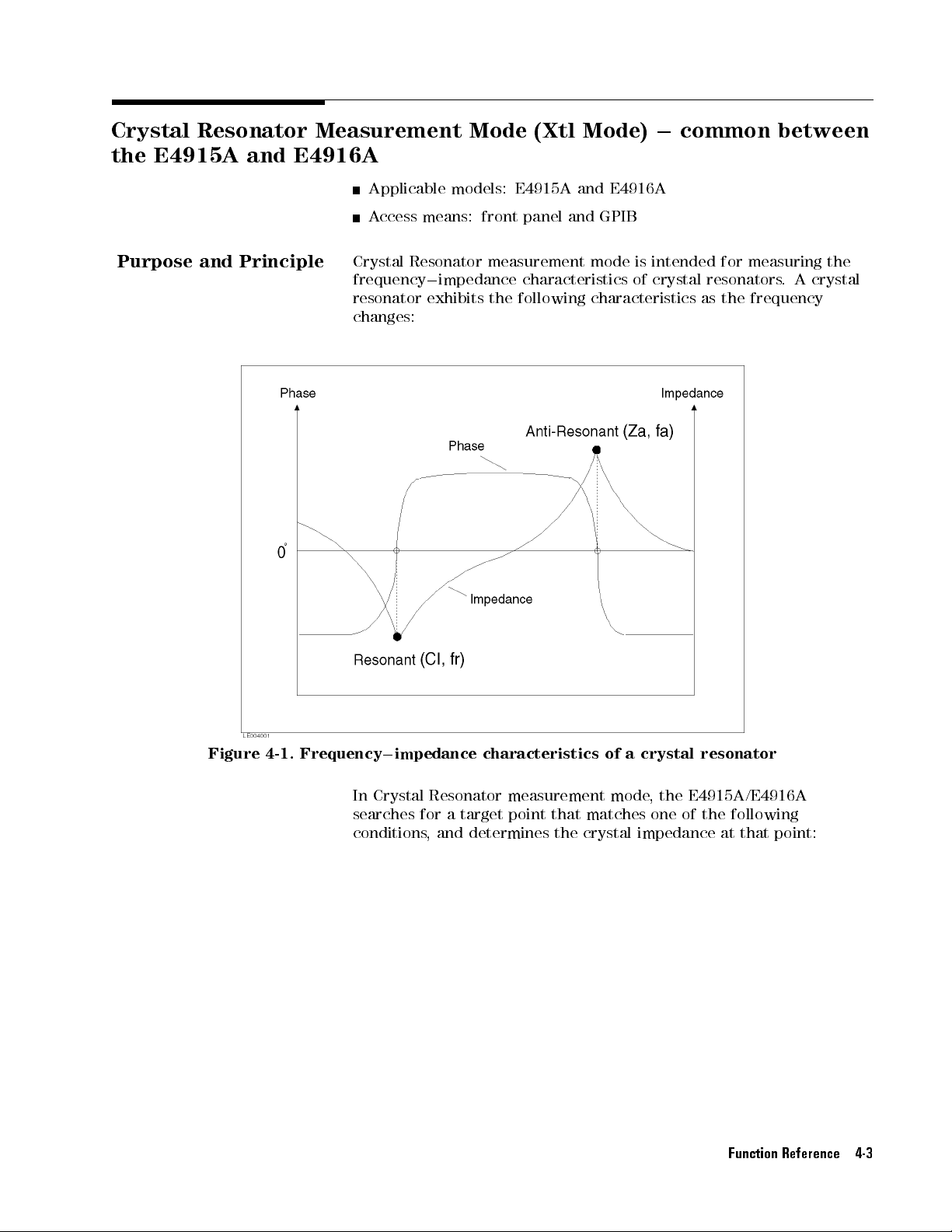
Crystal Resonator
the
E4915A
and
E4916A
Measurement Mode
(Xtl Mode)
0
common
between
Purpose
and
Principle
Applicable models:
Access
Crystal
frequency
resonator
means: front
Resonator
0
impedance
exhibits the
changes:
E4915A and
panel and
measurement
E4916A
GPIB
mode is
characteristics of
following characteristics
intended for
measuring the
crystal resonators
as the
frequency
.
A
crystal
Figure
4-1.
Frequency
In
searches for
conditions,
0
impedance
Crystal
characteristics
Resonator
a
target
and
determines
measurement
point
that
matches
the
crystal
of
mode
a
crystal
,
one
resonator
the
E4915A/E4916A
of
the
impedance
following
at
that
point:
Function Reference 4-3

Search
F
or TGT=PHASE
Targets
(Mainly
T
able 4-1.
and
Search
for
Conditions
Crystal
Resonators)
Measurement
parameter
Fr
Fs
FL
F
a
Measurement
parameter
Fr
Fs
FL
F
a Anti-
Search
target
Resonance
A
point
Series
P
resonance
point
Resonance
point
with
Resonance
capacitance
load
Anti-
A
resonance
point
Search
F
or TGT=PEAK
Search
target
Resonance
P
point
Series
P
resonance
point
Resonance
Resonance
point with
capacitance
load
P
resonance
point
lower frequency
oint with
the maximum
point
higher
frequency
T
able 4-2.
Targets
and
(Mainly for
eak
with
lowest
oint
with
the
point
eak with
highest impedance
point with
with
capacitance
point
Search
impedance
maximum
with
capacitance
Search
zero phase
conductance
with
zero
Conditions
Ceramic
Search
conductance
condition
load
phase
Resonators)
condition
load
4-4 Function Reference
Measurement parameters
on
the
LCD in
one
of
(characteristic parameters)
the
following
combinations:
can
be
displayed
Fr0CI
FL0RL
Fs0Zs
Fa0Za
Fs
indicates the frequency at the point with the maximum
conductance (Gmax) in the following circle diagram for admittance
characteristics:

Note
In
the
the
crystal
mode
F
L
impedance
resonator
capacitance
,
RL
of
the
and
trimming
is
displayed
crystal
the
function,
resonator
CL
on
instead
the
CL board.
neither
of
,
but the
the
the CI.
impedance of
And, in
CI
nor
RL doesn't
the target
the RL
is displayed.
mean
the
Search
Figure
Note
Algorithm
4-2. Circle
This
mode
diagram
Y
ou
can
display
combinations
on
soft
keys,
P
arameters"
The
E4915A/E4916A
for
zero
phase
depending
on
information
Measurement
subsection
.
for
admittance
measurement
using
the
refer
to
later
in this
or for
the
search
on
search
P
arameters"
describes
parameters
appropriate
\Search
Mode
section).
nds
a resonance
the positive
mode
modes
,
refer
later
the
measurement
characteristics
in
one
soft
key
.
and
P
air
point by
or
negative
currently
in
this
to
\Search
in
eect.
section.
algorithm
of
the valid
(F
or
more
of
Measurement
searching
peak
impedance
F
or
Mode
and
for
Fr search by phase mode
The E4915A/E4916A nds the resonance point by searching the
zero phase point. In this mode
, a zero cross point (the point whose
reactance value changes from negative to positive) is searched by
increasing the frequency in specied steps from lower frequency
in search range
than the zero phase point, the resonant
. (When you wish to obtain a resonant value other
value is searched by adding
the zero phase point as an oset value). And, if reactance value is
positive on the rst measurement point, then, an error will occur.
information
either
,
more
P
air
of
each
search
Serch Range1000ppm:
(smaller of 1000ppm or 20kHz) x
Serch Range<1000ppm:
Function Reference 4-5

depends
(smaller of
on the
the serch
range or
measurement speed
20kHz) x
HiQ O
HiQ
In
this
way
the
the zero
cross point,
frequency and
value
.
It, then,
E4915A/E4916A
the
step
frequency value
search goes
error will
Once
it
it
takes
the
reactance
changes
F
a
search
The
E4915A/E4916A
phase
susceptance
by
decreasing
by
phase
wish
to
resonant
value
.)
point, then,
occur and
decides
the
linearly
point.
mode)
obtain
value
And,
beyond the
slope
and
by
In
value
the
if
an
step frequency
SHORT
0.2 0.2
On
0.05
resonance point
the E4915A/E4916A
sets the
step frequency
starts searching
passes
the zero
and searches
search range
the
search
the
frequency
the
reactance
not
the
phase
and
is
possible
phase
this
mode
nds
mode
changes
the
,
the
from positive
frequency
from
higher frequency
a
resonant value
is
searched
by adding
susceptance
error
will
occur
is
same
as
Fr
Value
of the
search is
again for
cross point,
will
end.
range
and
determines
is
used
to
interpolate.
resonance
zero
cross
in specied
other than
value
is
negative
.
In
this
search
by
MED
0.04
performed. After
goes back
to 1/3
of
the
zero
it goes
again. While
or
a
timeout
where the
here
steps
in
the zero
because
point
point
to
negative)
search
the
resonance
by
(the point
(same
zero
phase
on
search,
phase
frequency
.
4/3
its
previous
cross
back
searching,
occurs
Fr
.
The
searching
as
range
phase
point
the
rst
LONG
0.1
0.04
passing
of
the
set
point.
and
,
a
search
point
slope
the
reactance
the
whose
is
searched
Fr
search
.
(When
point,
as
an
measurement
range
step
If
the
reduce
if
the
lies
of
zero
you
the
oset
of
,
the
4-6 Function Reference
In this
the zero
step
value
way
the
cross point,
frequency
.
It,
then,
resonance
the
and
sets
starts
searching
point
search
E4915A/E4916A
the
step
frequency
again
for
is
performed.
goes
to
1/3
the
zero
back
same
of
its
cross
After
value
previous
point. If
passing
of
set
the
E4915A/E4916A passes the zero cross point, it goes back and reduce
the step frequency value and searches again. While searching, if the
search goes beyond the search range or a timeout occurs
, a search
error will occur and the search will end.
Fr search by peak mode
The E4915A/E4916A nds the resonance point by searching the
maximum impedance point. In this mode
, the maximum impedance
point is searched by decreasing in specied steps (same as Fr search
by phase mode) from higher frequency in search range.
In this way the resonance point search is performed. After the
impedance value of change alters from positive to negative, the
E4915A/E4916A sets the step frequency to 1/3 of its previous set
value and back to the opposite direction. It, then, starts searching
the

P
arameters
and
Their
again.
alters
and
searches again.
search
search
Fs
search
The
E4915A/E4916A
maximum
maximum
(same
range
.
In
this
admittance
E4915A/E4916A
set
value
searching
E4915A/E4916A
conductance
Settings
This
subsection
the
E4915A/E4916A
parameters
Note
that
front
panel
displayed
If the
E4915A/E4916A detects
from positive
range or
a
will end.
admittance
admittance
as
Fr
search
way
the
resonance
value
of
sets
and
back
again.
After
performs
point.
describes
are
accessible
the
term
while
on
and
accessible
to
negatice
While
timeout
nds
and
point
by
phase
change
the
to
the
performing
in
Crystal
hard key
the
term
,
it
reduces
searching,
occurs
,
a
the
resonance
conductance
is
searched
mode)
point
search
alters
from
step
frequency
opposite
direction.
this
same
procedure
the
parameters
Resonator
via
either a
refers
soft key
through
the
if
the
search
points
by
from
is
positive
procedure
hard
to
physical
refers
the
LCD screen.
impedance
the
step
frequency
search
error
point
by
.
In
goes
will
searching
this
increasing
lower
frequency
performed.
to
negative
to
1/4
of
its
It,
then,
four
for
searching
that
control
measurement
key
or
a
keys
to
a
pair
value
beyond
occur
mode
in
specied
in
After
previous
starts
times
maximum
the
behavior
mode
soft
key
provided
of
parameters
of
change
value
and
the
,
the
search
the
,
the
,
the
.
,
or
on
the
the
steps
of
These
both.
the
P
arameters
FREQ
frequency (Fr)
specied here
range.
Soft key:
Hard
GPIB
CI
:
:
Lets
The unit
key:
command:
Lets
that
you
you
determine
specify
or
anti-resonance
is used
is
MHz.
NN
NN
NN
N
N
N
N
N
N
N
N
FREQ
5
4
F
req
specify
nominal
the
as
the
NOMFreq
the
nominal
nominal
frequency
center
t
<
value
value for
values
value
frequency
>
for
the
(F
crystal
resonance
a).
The
for
the
value
search
impedance
This nominal value is used as the basis for level control (with
ALC mode OFF). Also
as the reference value for Delta mode
Delta mode
Soft key:
Hard key:
, refer to \Delta Mode
N
NNNNNNN
CI
4
Nominal CI
GPIB command: NOMCI
, you can use your specied nominal value
.(F
or more information on
" later in this section.
5
t<value
>
Parameters that determine measuring conditions
RNG
: Search range. Specify the resonance point search range in
ppm or Hz.
NNNNNNNNNNN
Soft key:
Hard key:
RNG
4
Freq
5
.
Function Reference 4-7
Note
GPIB
LVL
device
Soft
Hard key:
GPIB command:
POWEr
UNIT
by selecting
Soft
Hard
GPIB
The
signal
actually
the
unit
at
the
port
With
the E4915A,
TGT
\Search Mode
section.
Soft
Hard
GPIB
PHAS
Soft
Hard
GPIB
command: SRCHRange
: Lets
you specify
:
Lets
at the
key:
key:
N
N
LVL
t
<
value
you
dBm, W
N
NN
UNIT
tip of
N
N
N
N
NN
NN
4
Level
specify
NN
NN
NN
N
N
5
>
N
N
N
N
the jig.
[mW
A
key:|
command:
level
applied
of
the
of
:
Lets
key:
specied
to
signal
the
you
N
N
TGT
POWEr
a resonator
level,
E4916A
the
output
specify
and
P
air
N
N
N
N
N
N
N
N
N
key:|
command:
: Lets
key:
you
N
N
PHAS
specify
N
N
N
N
N
N
N
N
SRCHTGT
N
N
N
N
key:|
command: TGTPhase
the power
j
UW
j
the
unit
TT
,
AMP
t
<
with
the E4915A
. However
the
specied
instead
power
the
search
of
Measurement
the
target
t
<
value
level which
NW
j
W
of
the
,
or
V
value
of
the
level
target:
tf
PHase
phase
t
<
value
>
is applied
j
MA
j
U
A
j
A
j
MV
power level
OL
T
.
>
indicates the
,
when
you
level shows
power applied
is
xed
at
Phase
P
arameters"
j
PEak
g
value
>
j
UV
specify
the
-5
or
in
degrees
j
N
N
N
N
LVL
(
power
signal
to
dBm.
P
eak.
to the
V
j
DBM]
N
N
N
N
N
N
N
soft
dBm
a
resonator
Refer
later
(
level
in
).
key)
as
.
to
this
4-8 Function Reference
PARA
:
Lets
you
select
one
of
the
valid
Fr
,
FL,
Fs
,
and
F
a.
N
N
N
N
N
N
N
N
N
N
N
NN
N
key:
key:|
PARA
ARAtfFRjFAjFSjFL
the Equivalent Circuit Analysis function
equivalent circuit analysis
"
the Equivalent Circuit Analysis
Soft
Hard
GPIB command: MEASP
Parameters associated with
(for more information on
\Equivalent Circuit Analysis Function
EQUC
: Lets you turn ON/OFF
function.
NNNNNNNNNNNNNN
Soft key:
Hard key:
EQUC
4
(blue)
5+4
/M (Equiv Ckt)
5
GPIB command: EQUCkttfDEV4jDEV6jOFF
DspQ
: Lets you show or hide the Q parameter.
NNNNNNNNNNNNN
N
Soft key:
DspQ
measurement
parameters:
g
, refer to
later in this section)
g

Hard
key:|
GPIB
command: DSPQ
P
arameters associated
on
capacitance load,
(
CL_a
/
CL_t
)"
later in
CL_a
: This
connected to
value
Soft
Hard
GPIB
CL_t
: This
wish
N
N
N
N
NN
NN
NN
N
N
N
CL_t
is
pF
.
Soft
Hard
GPIB
parameter indicates
the DUT
from
ENTRY
N
N
N
N
N
N
N
N
CL_a
key:
key:
4
CL
command: CLA
parameter indicates
to obtain
N
soft
key:
key:
for the
key and
N
N
N
N
N
N
N
N
CL_t
4
CL
command:
tf
with capacitance
refer to
this
section)
.
Select
block.
N
NN
NN
N
5
Value
CT
T
ARGET
enter the
N
N
N
N
N
N
5
Value
CL
TGT
t
OFF
j
ON
\Target
the
the
The unit
t
<
value
the
capacitance
value from
<
value
j
0
j
1
g
load (for
Capacitance
actual
NN
NN
NN
N
N
N
N
N
N
N
N
CL_a
soft
is pF
.
>
load
capacitance
ENTRY
>
more
trimming
capacitance
key and
value
.
Select
block.
information
Function
load
enter
the
value
you
the
The
unit
Note
Y
ou
can't
mode
P
arameters
CKT
specify
except
:
Lets
the
FLtrim
associated
you
specify
measurement. (F
Measuring Circuit
N
N
N
N
N
N
N
Soft
Hard
GPIB
PICKTtype
ALC
:
Lets
ALC
mode
Soft key:
CKT
key:
key:|
command:
tf
you
turn
,
refer
N
N
N
N
NN
ALC
NN
Hard key:|
GPIB command: ALC
TIME
: Lets you specify the
three alternative settings:
NNNNNNNNNNNNN
Soft key:
Hard key:
N
TIME
4
Meas Time
GPIB command: MEASTime
CL
value
by
4
Meas
with
the
or
more
Type
N
N
N
N
CIRcuit
PI41900A
ON/OFF
to
\ALC
NN
N
5
for
Prmtr
other
type
a
CL
5
.
measurement
of
the
information,
or
CL
circuit
refer
t,
when
functions
to
to
\Selecting
be
you
used
").
tf
PI
j
j
PI41901A
ALC
Mode
tf
OFF
PRObe
"
jONj0j1g
j
PI41902A
mode
later
j
BRIdge
.
(F
or
in
this
g
g
more information
section).
measuring time by selecting one of
Short,Med
t<value
,
and
>
Long
.
select
for
the
the
on
HI Q
: Lets you turn ON/OFF High Q mode.(For more information
on High Q mode, refer to \High Q Mode" later in this section).
NNNNNNNNNNNNNN
Soft key:
HI Q
Hard key:|
GPIB command: MEASTimet<
value
>
Function Reference 4-9

Note
AGE
:Lets
on
Aging mode
Soft key:
Hard key:|
GPIB command:
Time
:
Lets
(F
or
more
later
in
Soft
key:
Hard
GPIB
T
o
set
the
4
5
key
Select
entry
mode
Some
parameters
other
parameters
choose
chosen
the
o,press
4
Enter
an
the
5
4
you turn
, refer
NN
NN
NN
NN
N
AGE
you
information
this
section).
N
NN
NN
NN
NN
Time
key:|
command:
value
of
next
to
.
option,
desired
key
to
put
5
,
4
(blue)
BkSp
ON/OFF Aging
to \Aging
NN
AGING
enter
the
on
N
N
N
N
N
A
GINGTIME
a
parameter
the
soft
accept
accept
use
the
your
only
4
option
the
new
(Entry
tf
length
Aging
key
*
)
or
entered
O
)
5
Mode"
OFF
j
ON
of
mode
t
<
accessible
to
put
manually
one
of
5
or
4
(
setting
.
mode.
later
j
0
j
1
g
aging
,
refer
value
>
via
the
LCD
entered
the
presented
5
key
+
the
appropriate
into
eect.T
(F
or
more
in
this
interval
to
[S
j
MS
j
a
soft
screen
value
.
When
o
information
section).
(in
\Aging
M]
key
into data
while
options
you
value
turn
seconds).
Mode
"
,
press
the
.
T
o
have
, press
the entry
the
of
When
next
Search
The
whether
value
the
screen
no
soft
pair
of
Mode
search
pair
mode
to
nd
or
an
impedance
of
measurement
in
each
Search
Measurement
key
is
soft
keys
and
P
,
which
a
resonance
of Phase
Mode
selected yet,
air
peak.
Search
Parameters
Fr0CI Phase
FL0RL Phase
Fs0Zs Gmax (maximum
Fa0Za Phase peak
by pressing
of
Measurement
can
be
either
point
The
parameters
and P
eak modes
T
able
and
Measurement P
Mode
PEAK
PEAK
conductance)
PEAK
you
can
the
4
*
Phase
by
searching
following
to
be
.
4-3.
access
5
)
or
table
displayed
the
or
P
arameters
5
4
(
+
P
eak, determines
for
a
particular
shows
on
arameters
F
F
FF
FF
FF
F
TGT
soft
key
Phase Fr
Peak
Phase FL
Peak FL
0
Phase Fa
Peak Fa
previous
key
.
how
the LCD
F
F
FF
FF
FF
F
F
F
F
PARA
soft
Fr
FS
phase
to
or
select
key
4-10 Function Reference

Measurement
Functions
This
subsection
Crystal
describes
Resonator
the
measurement
measurement
mode
.
functions
available
in
Note
Measuring
Resonant
Connected
The
E4915A/E4916A
resonant
Press
this
resonator
In
the
the
crystal
T
arget
In
some
CL
the
capacitance
E4915A/E4916A
which
trim
board
calculates
value
frequency
4
Meas
Prmtr
function.
is
inserted
mode
F
L
impedance
resonator
Capacitance
situations
adapter
board
reference
causing
can
help
the
CL
value
whose
the
and
the
5
and
The
,
RL
of
and
resonator
provides
you
CL
value
eect
adapter
resonant frequency
Frequency
incorporates
)
with
(F
L
select
FL
value
F
the
L
in
is
is
the
displayed
crystal
the
CL
trimming
,
you
may
want
or
you
may
due
to
the
eective
the
in
such
situations.
on
condition
is
close
caused
by
board
expected when
)
with
(F
L
the
capability
capacitive
as
the
displayed
load
measurement parameter
immediately
xture connected
instead
resonator
on
the
CL
of
,
but
board.
the
the
Function
to
trim
a
CL value
have
unwanted
CL
target
that you
to
the target
the
dierence
CL
value
trouble
capacitance trimming
the
in
factors
value
to
This
function
connect
CL
to
determine an
target
Capacitive
to
measure the
connected.
after
with the
CI.
RL
doesn't
impedance
(
CL_a
/
CL_t
of the
adjusting
such
increase
.
allows
the
CL
value
.
This
between
CL
value
Load
to use
the
crystal
CL board.
mean
of
the
)
of
F
L
as
stray
The
function
you
to
adapter
function
the target
approximate
is
connected.
CL
Note
Note
Note
To
use this
and trimming
value (CL a) and
function,
mode and
the T
rst,
select
then specify
appropriate
the
ARGET capacitance
A
CTU
value
CL
AL
adapter
(CL
board
capacitance
t) for
the
E4915A/E4916A.
The
target
calculation
not
trim
not
wish to
not use this
In
the target capacitance trimming function, neither the CI nor the RL
capacitance
result
the
actual
use
any
function.
trimming
of
an
approximate
CL
of
the
approximate
CL
function
F
L
adapter
value
for
only
provides
value
.
This
board.
measurement
the
means
Therefore,
results
that
if you
it
,
does
do
is displayed.
If the target CL value and
greatly, readout may become unstable or
the CL value for the adapter board dier
measurement may fail. Be
sure to select an appropriate CL adapter board.
Selecting a CL adapter board
Select a CL adapter board whose capacitance value is the closest to
the target CL value. The target capacitance trimming function can
calculate an approximate value more accurately as the dierence
do
Function Reference 4-11

Note
between
becomes
adapter
measurement
Even
or
including
do
Procedure
P
erform
trimming
the target
smaller.
board dier
if
a correct
measurement
Q
not
use the
the
function.
CL value
If
the
target
greatly
may fail.
CL adapter
may fail.
of the
crystal resonator
target capacitance
following
procedure
and
CL
,
readout
board is
This can
the
actually
value
may
selected, readout
be caused
to be
trimming function.
to
use
loaded
and
the
CL
become
by several
measured. If
the
target
CL
value
value
for
unstable
capacitance
or
may vary
factors
this
is
the
the
case
,
Note
Note
Connect
Press
Param:
Select
Enter
board
N
NN
NN
N
N
N
N
N
N
N
CL_a:nnnn
enter
Enter
the
T
N
N
N
N
N
N
N
N
NN
N
N
CL_t:nnnn
enter
Always
value
of
close
to
the
A
CTU
becomes
values
,
Y
ou
can't
mode
except
the
4
Meas
Fs
FLtrim
the
capacitance
for
the
N
N
N
N
N
N
N
N
N
N
N
N
N
N
NN
the
A
the
load
ARGET
N
N
N
N
N
N
N
N
N
N
N
N
N
N
N
the
T
keep
the
CL
the
T
AL
rather
select
specify
proper
Prmtr
Fr
NN
N
N
N
N
N
F
CTU
capacitance
N
N
N
N
N
N
NN
F
ARGET
the
ARGET
capacitance
great
the
FLtrim
CL
5
to
display
Fa
FL
.
A
CTU
AL
(
4
(Upp
er
AL
capacitance
capacitance
(
4
(Lo
w
er
capacitance
A
CTU
AL
adapter
capacitance
while
closest
the CL
by
adapter
the
FLtrim
value
of
capacitance
5
)
select)
select)
4
and
value
value
5
)
and
capacitance
board
actually
value
you
CL
adapter board
value for
Meas
Prmtr
board
following:
the
actually
value (CL
use
value
you
(CL
use
value
value
and
the
are
trying
CL
5
.
to
the
keys
on
.
wish
to
t).
Press
keys on
.
value
,
which
connected
.
If
the
T
ARGET
many
again.
a
or
CL
41902A
connected CL
the
obtain
4
CL
the
dierence
t,
.
a).
Press
ENTRY
for
5
V
alue
ENTRY
is
the
to
the
between
capacitance
dierent
when
you
adapter
V
alue
block
value
select
5
to
to
xture
the
4
CL
block
capacitance
test
T
ARGET
,
4-12 Function Reference
Equivalent Circuit Analysis Function
The
Equivalent Circuit Analysis function allows you to determine the
4- or
6-element equivalent circuit that corresponds to the DUT
access this mode
hard key, and choose one of the three options presented:
OFF: Equivalent Circuit Analysis function OFF
4DEV: Equivalent Circuit Analysis function ON (4-element)
6DEV: Equivalent Circuit Analysis function (6-element)
, use the
NNNNNN
NNNNNNNN
EQUC
soft key or
4
(blue)
5+4
/M (Equiv Ckt)
.T
o
5

Figure
The
Equivalent
C0,
C1,
Y
ou
can
The
LCD
eight
equivalent
at
a
time
on
the
settings
following
L1,
R1,
show
screen
.
Which
table:
Settings
4-3.
Circuit
G0,
or
hide
of
circuit
of
EQUC
F
our-
and
Analysis
and
Q
the
Q
the
E4915A/E4916A
parameters
four
parameters
the
soft
of
EQUC
Displayed
setting
six-element
function
parameters
parameter
(plus
are
N
NN
N
N
N
N
N
N
N
N
EQUC
keys
T
able
and
DspQ
DspQ
setting
equivalent
calculates
.
using
can
only
two
displayed
N
NN
N
N
and
N
DspQ
N
N
N
4-4.
and
Combinations
Constants
Constants
the
N
N
N
N
N
N
N
N
N
N
N
N
N
N
DspQ
the
display four
parameters:
at
a
N
N
N
time
N
N
N
N
N
,
as
shown
displayed
circuits
values
soft
key
Fr
depends
in
of
of
.
of
and
the
the
the
CI)
Note
Note
It
is
recommended
with
no
capacitance
connected
return
incorrect
with
4DEV
4DEV
6DEV
6DEV OFF
to
use
load
capacitance
values
.
ON
OFF
ON
the
Equivalent
connected
load,
C1,
C0,
C1,
R0,
C0,
C1,
Circuit
to
the
DUT
the
E4915A/E4916A
R1,
Q
R1,
G0,
Q
R1,
Analysis
.
If
L1
L1
the
function
DUT
may
is
possibly
High Q Mode
High Q mode is intended for use when the DUT has a high Q value
and it provides longer measuring time
NNNNNNNNNNNNNN
the
Hi-Q
soft key
.
.T
o enable High Q mode
,
, use
Turning ON High Q mode causes the three measuring time settings
(
Short,Med
,and
Long
) to provide a longer measurement time than
with High Q mode OFF.
The E4915A/E4916A provides the three alternative measuring time
settings (
Short,Med
, and
Long
) with High Q Mode OFF, plus the three
other alternative settings with High Q mode ON; thus, 6 alternative
settings in all. To control the measuring time via the GPIB, issue the
MEASTime command followed by an integer from 1 to 6.
Function Reference 4-13

T
able 4-5.
P
arameter
High Q
Meas
time
Mode
High
Q
Note
Note
ALC
Mode
ALC
(A
uto
soft
key,
apply
level
control
.
the
Mode
mode
.
time interval
Level
N
N
N
N
NN
NN
NN
N
ALC
actually
OFF
,
value
T
o
enter
Aging
Aging
the
E4915A/E4916A
intervals
T
o
set the
that
appears
to
confuse this
measurement
sum
of
the
time
Control)
provides level
the
specied
is
performed
nominal
,
which
can
to
in
pair
with,
key with
time
.
The
interval,not
1 Short
2
3
4 Short
5
6
mode
CI
value
be
repeat
for
and
the
time
Med
Long OFF
Med
Long
,
which
control based
power
to
based
,
use the
turned
ON
measurement
Aging
below
N
N
N
NN
NN
N
TIME
value
mode
N
N
N
N
N
N
soft key
,
returned
elapsed
can
the
on
4
Nominal
via
,
the
time
OFF
OFF
ON
ON
ON
be
turned
on the
DUT
.
When
the
user-specied
5
CI
N
N
N
N
N
N
AGE
the
cycles
use
the
AGE
key
that lets
from
from
the
ON
via
actual
this
CI
mode
nominal
hard
key
.
N
N
N
N
N
soft
key
,
at user-specied
N
N
N
N
N
N
N
NN
N
N
N
N
N
Time
soft
key
.
T
ake
care
you
set
*TRG
FETCH
aging
start.
the
value
causes
not
the
to
is
CI
is
the
Output
of
Measurement
Note
4-14 Function Reference
Results
LCD Screen
Characteristic parameters: Fr
0
RL, FL
0
CI, Fs
0
Zs,
or F
a0Za
4- or 6-element equivalent circuit constants: four of the C0, C1,
L1, R1, G0, and Q parameters as specied by the user (output only
when the Equivalent Circuit Analysis function is ON)
E4915A/E4916A The LCD screen of the E4915A/E4916A can display
up to 6 parameters at a time.
GPIB
Characteristic parameters: FrjFajFsjFL, CIjZajZs

4-
and
ON)
or
6-element
Q
(output
equivalent
only
when
circuit
the
Equivalent
constants:
Circuit
C0,
Analysis
C1,
L1,
R1, G0,
function is
R0,
Note
Note
Elapsed
Comparator
GPIB
talk
Characteristic
4-
or
6-element
and
Q
(if
Elapsed
LED
Output
LED
1:
LED
2:
For
the Comparator
in
this
chapter
Beep
Beep
Output
sound
test.
F
or
the
Comparator
in
this
chapter
time
for
Aging
result
only
mode
parameters:
equivalent
Aging
time
for
mode
Aging
Comparator
Comparator
.
is
output
.
mode
(if Aging
(for
output
Fr
j
F
circuit
is ON)
mode
(if
result for
result
for
Fr value
CI
function, refer
when
a
DUT
function,
refer
mode is
to
printer)
a
j
Fs
,
FL, CI
constants: C0,
Aging
mode is
value
to
refer
has
passed
to refer
ON)
j
Za
j
Zs
C1, L1,
ON)
to
\Comparator
or
failed
to
\Comparator
R1, G0,
Function
the
comparator
Function
R0,
"
"
Handler
Refer to
Analog OUT
Outputs a
-5V
P
arameters
to
+
Interface
Appendix
T
erminal
DC voltage
5V
in
proportion
and
C
\Handler
signal
Their
Interface
whose
to
the
Settings
Fr
level
,
Fs
."
changes
,
FL,
or F
within
a value
.
the
range
The parameters for controlling the output through the Analog OUT
terminal are accessible via the corresponding soft keys contained
in the System menu. (T
4
5+4
0
(blue)
AnalogOut
(System)
: Lets you turn ON/OFF the DC
5
key).
o
access the System menu, press the
voltage output through
the Analog OUT terminal.
N
NNNN
Soft key:
NNNNNNNNNNNNNNNNNNNNNNNN
AnalogOut
Hard key:|
GPIB command: ANLGOUTtfOFFjONj0j1
Settings
: Lets you specify the coecient of the DC voltage
g
output from the Analog OUT terminal and the measured
frequency. The system increments or decrements the output
voltage by 1 V as the frequency changes by the amount
of
Function Reference 4-15
represented
soft
key,
you are
due
to a
change in
Y
ou can
choose one
Soft key:
Hard
key:|
GPIB
command:
by
this
coecient.
presented
voltag
of
NN
NN
NN
N
N
N
N
N
N
N
N
N
N
N
NN
Settings
ANLGDFDV
NN
NN
them
NN
N
with
(
dFdv
and
When
two
)
and
enter
t
<
value
you
select
options:
reference
your
desired
>
,
ANLGREF
N
N
N
N
N
Settings
the
a
change
frequency(
value
t
N
N
N
N
N
NN
NN
NN
NN
NN
NN
N
N
frequency
REF
).
.
<
value
N
N
>
4-16 Function Reference
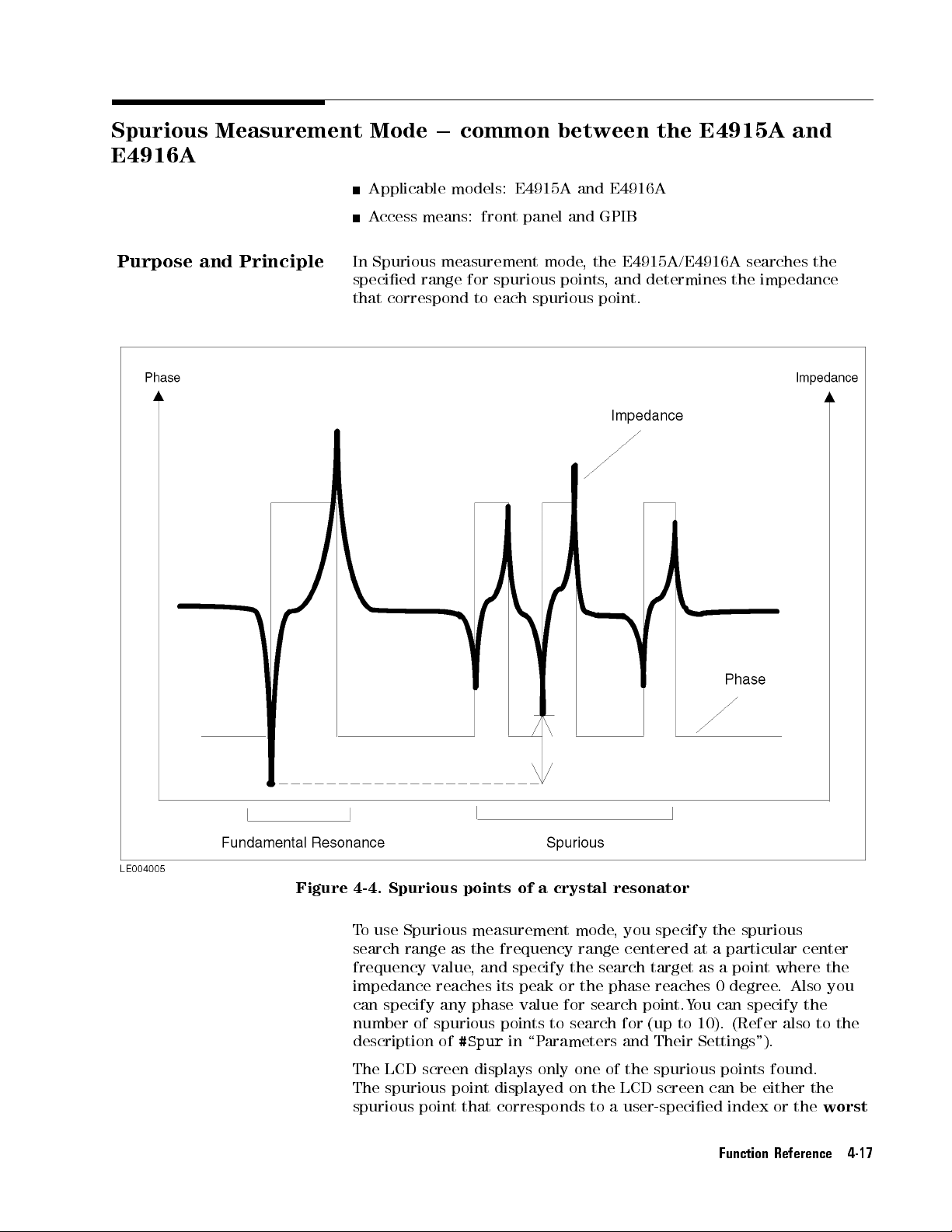
Spurious Measurement
E4916A
Mode
0
common between
the E4915A
and
Purpose
and
Principle
Applicable models:
Access
In
Spurious
specied
that
means: front
measurement
range for
correspond to
E4915A and
panel and
mode,
spurious points
each spurious
E4916A
GPIB
the E4915A/E4916A
,and
determines
point.
searches the
the
impedance
Figure 4-4. Spurious points of a crystal resonator
To use Spurious
measurement mode
, you specify the spurious
search range as the frequency range centered at a particular center
frequency value
, and specify the search target as a point where the
impedance reaches its peak or the phase reaches 0 degree
can specify any phase value for search point.You can specify the
number of spurious points to search for (up to 10). (Refer also to the
description of
#Spur
in \Parameters and Their Settings").
The LCD screen displays only one of the spurious points found.
The spurious point displayed on the LCD screen can be either the
spurious point that corresponds to a user-specied index or the
. Also you
worst
Function Reference 4-17
spurious
in
\Parameters
for
the spurious
point
with the
spurious
negative
,
depending
and Their
point with
second smallest
means
the
impedance
on
the
Settings").
spurious
peak
is
setting
the
smallest
frequency
point
where
maximum.
of
F
the
or
N
N
N
N
N
N
N
N
N
N
NN
NN
NN
DispSP
the
index,
frequency
,
and
so
the
magnitude
NN
NN
,
on.
soft
you
2
for
The
key
can
the
worst
of
(described
specify
1
spurious
the
Note
P
arameters and
Their
When
E4915A/E4916A
specied
Measurement
The
a
simple
a
predetermined
waveform
DUT
recommended
Settings
This
subsection
of
the
parameters
P
arameters
CENT
search
you
are
using
Spurious
outputs
by
SPNUM.
Results").
E4915A/E4916A
facility
to
frequency
is
free
from
is
expected to
to
use
describes
E4915A/E4916A
are
accessible
that
determine
:
Lets
you
specify
range
.
The
N
N
N
N
N
N
N
N
N
N
Soft
Hard
GPIB
CENT
key:
key:|
command:
measurement
the
measurement
(F
or
more
information,
provides
search
Spurious
for
spurious response
range
remarkable
exhibit complex
a
network analyzer
the
parameters
in
Spurious
via
either
measuring
the
center
unit
is
MHz.
N
N
N
N
SPCENT
er
mode
results
measurement mode
,
on
the assumption
irregularities
characteristics,
, instead.
that
measurement
a
hard
key
conditions
frequency
t
<
value
>
via
for
refer
to
points within
. Thus
control
mode
or
a
for
the
GPIB
spurious
\Output
of
as
that the
,if
the
it
is
highly
the
behavior
.
These
soft
key
,
or
the spurious
,
the
points
both.
4-18 Function Reference
RNG
:
Lets
you
specify
KHz,Hz or
Soft
Hard
GPIB
DispSP
ppm.
N
N
N
N
N
N
NN
RNG
key:
key:|
command:
:
Determines
NN
N
LCD. This soft key provides two alternative options:
Nth
.Usethe
Worst
the
spurious
SPRANGe
which
spurious
t
<
value
search
>
[
f
point to
range
Hz
option to display the worst
.
The
j
Ppm
g
]
be
displayed
spurious point
unit
Worst
on
is
the
and
(i.e., the spurious point where the impedance value reaches the
maximum negative peak). On the other hand, the
Nth
option
allows you to specify the index number of the spurious point you
want displayed; for example
point with the smallest frequency
the second smallest frequency
, you can specify
1
for the spurious
, 2 for the spurious point with
, and so
on.
NNNNNNNNNNNNNNNNNNNN
Soft key:
DispSP
Hard key:|
GPIB command: SPDISPtfWorstjNth[,<value>]
TGT
: Lets you specify the spurious search target: Phase or Peak.
g

Soft
Hard
GPIB
PHAS
: Lets
Soft key:
Hard
GPIB
#Spur
for
.
The
lowest
#Spur
Soft
Hard
GPIB
N
NN
NN
NN
NN
NN
TGT
key:
key:|
command: SPTGT
you
specify
NN
NN
NN
NN
N
N
N
N
N
N
PHAS
key:|
command:
:
Lets
you
specify
E4915A/E4916A
frequency
to
.
N
N
N
N
N
N
N
N
N
N
N
N
N
N
N
N
N
#Spur
key:
key:|
command:
tf
the
SPPHAse
the
searches
high
frequency
SPNUM
t
PHase
target
t
<
number
<
value
j
PEak
phase
value
spurious
>
in
>
of
the
g
value
in
spurious
points
search
degrees
points
from
range
(
to
the
until
).
search
Output
of
Measurement Results
The results
of Spurious
Crystal resonator
the LCD
to a
setting
Settings").
GPIB
for spurious
The
Spurious
Ratio
spurious
20log
The
screen can
user-specied index
of
the
N
N
N
N
DispSP
When
,
however
,
points
output items
frequency for
of
crystal
point
f
(Z
value
number
of
measurement
measurement. The
be
either
N
N
N
N
N
N
NN
NN
N
N
N
N
N
N
soft
you
are
the
E4915A/E4916A
or
using
the
the
key
specied.
are
as
follows:
each spurious
impedance
detected
at
spurious
spurious
at
and
point)
points
CI
are
spurious point
spurious
worst
spurious
(described
Spurious
outputs
each
value
at
/
(CI
detected
output
in
along
point
that
,
depending
\P
arameters and
measurement
the
measurement
point
detected
FR
value)
g
with
those
displayed
corresponds
on
mode via
of
on
the
Their
the
results
Function Reference 4-19

Drive Level
Dependency Measurement
Mode (DLD
Mode)
Purpose
and Principle
Applicable
A
ccess means:
Drive
Level
determining
that
is
,
how
resonator
E4916A
are
sweeps
resonance
impedance
Figure
crystal
4-5
resonator
Model: E4916A
front panel
Dependency
the
drive
the
frequency
inuenced
the
drive
frequency
at
the
shows
at
resonance
a
typical example
.
only
and GPIB
measurement
level
dependency
0
impedance
by
changes
level
each
sweep
point.
in
in
a specied
point,
of the
mode
is
intended
of
a
crystal
resonator
characteristics of
drive level.
manner,
In this
searches for
and determines
drive level
dependency
for
,
a crystal
mode,
the crystal
the
the
of
a
4-20 Function Reference
Figure
4-5. Drive
When
choose
When
of
How T
level
up
you
one
you
to
dependency
are
using
of
three
are
using
100
sweep
points
DLD
sweep
DLD
of
a
crystal
mode
patterns:
mode
.
F
or more
through
UP
via
the
information,
resonator
the
,
UP-DOWN,
GPIB,
o Sweep the Drive Level" later in this section.
front
you can
panel,
and
also dene
refer
you
to
Which measurement parameters (characteristic values) can be
determined diers depending on whether you are using DLD mode
through
the front panel or via the GPIB
, as shown in the following
table:
can
UP-MIN.
alist
\Specifying

P
arameters
and
Their
Fr
CI value
Dierence
Dierence
Maximum
Maximum
Minimum
Fr and
Settings
This
of
the
mode). These
key,
Measurement
value at
each level
at each
between
between
and
value
value
CI values
subsection
E4916A
or both.
Parameters
P
arameter
level
the
maximum
the
maximum
minimum
of
of
describes
in
values
CI
CI
at reference
Drive
Level
level
the
parameters are
T
able 4-6.
Determined
and
minimum
and
minimum
of Fr
parameters
Dependency
accessible
in
values
of
values
of
that
control
measurement
via
either
Fr
CI
a
DLD
Front
the
hard
Mode
panel
GPIB
p
p
p p
p
p p
p
operation
mode
(DLD
key
or
a
p
p
p
p
p
p
soft
Parameters
FREQ
frequency
specied
range
Soft
Hard
GPIB
Nominal
impedance
level
Soft
Hard
GPIB
P
arameters
RNG
Soft key:
that determine
:
Lets you
.
The
key:
key:
command:
setting
key:
key:
(Fr)
here
unit
CI
:
.
specify
or
anti-resonance
is
used
is
MHz.
N
N
N
N
N
NN
N
N
N
N
N
N
N
FREQ
5
4
F
req
Lets
you
This
nominal
(with
ALC
N
N
N
N
N
N
N
N
CI
4
Nominal
the
as
NOMFreq
specify
mode
5
CI
command: NOMCI
that
determine
: Lets you specify the
N
NNNNNNNNNN
RNG
nominal values
nominal
the
value
center
t
value
frequency
frequency
<
value
>
the
nominal value
is used
for
as the
resonance
(F
a).
for
basis for
OFF).
t
<
value
>
measuring
conditions
search range in Hz or ppm.
The
value
the
search
for crystal
power
Hard key:
GPIB command: SRCHRange
SWEP
: Lets you choose one of
UP DOWN, UP MINFor more information on level sweep
t<value
>
three alternative sweep types: UP
, refer to
\Specifying How To Sweep the Drive Level" later in this section.
NNNNNNNNNNNNNN
Soft key:
SWEP
Hard key:|
GPIB command: PTSWPTypetfUPDOWNjUPjUPMINjLIST
,
g
MIN
: Lets you specify the minimum drive level value. Use the
NNNNNNNNNNNNNN
UNIT
soft key to specify the unit for this value.
Function Reference 4-21
Soft
key:
Hard
key:|
GPIB
command: PTMINP
MAX
:Lets
N
N
N
soft
key:
key:|
command:
:Lets
N
N
soft
will
CI
values
key:
key:|
command:
:
Lets
key:
key:|
command:
you
key
you specify
key to
dBm
ower
ower
ower
NN
NN
N
N
N
N
N
N
N
UNIT
Soft
Hard
GPIB
STD
N
N
N
N
NN
NN
NN
NN
UNIT
function
and
\Comparator
Soft
Hard
GPIB
UNIT
choosing
Soft
Hard
GPIB
PTMINP
PTMAXP
PTSTDP
N
NN
NN
NN
NN
MIN
specify
to
N
N
N
N
N
N
N
N
N
MAX
sort
at
Function
NN
N
N
N
N
N
N
N
STD
you
specify
,
WATT
NN
N
N
N
N
N
N
N
UNIT
t
t
NN
the
specify
N
N
PTMAXP
the reference
specify the
the
measurement
the
drive
"
N
N
PTSTDP
the
,
AMP
N
N
N
N
N
<
value
t
<
value
<
value
ower
maximum
the
ower
level.
later
ower
unit
,
or
VOLT
>
[mW
>
[mW
>
[mW
t
<
unit
for
t
<
unit for
(F
or
in
this
t
<
for
.
j
UW
j
NW
j
UW
j
j
UW
j
NW
value
>
drive
this
value
drive
this value
values
more
chapter).
value
>
the
drive
j
W
j
NW
j
W
j
W
j
level
value
value
.
>
level
value
.
The
based
on
information,
level
MA
j
U
A
j
A
j
MA
j
U
A
j
A
MA
j
U
A
j
A
.
Use
.
Use
Comparator
the
Fr
refer
values by
j
MV
j
UV
j
MV
j
UV
j
MV
j
UV
the
the
(Fs)
j
V
j
j
V
V
to
j
DBM],
j
DBM],
j
DBM]
Note
The
signal
actually
the
unit
at
the
With
WAIT
to
TRKG
function is ON, the resonance
searched by sweeping the drive level
the resonance point. When it is
is detected by Fr search and then
frequency maintained.
level
specied
applied
of
port
the
E4915A,
:
be
Soft key:
Hard key:|
GPIB command: PTW
: Turns ON/OFF the Phase Tracking function. When this
Soft key:
Hard key:|
GPIB command: PTRACKtfONjOFFj0j1
the
of
the
Lets
stable
to
a
signal
E4916A
the
you
after
N
N
N
N
N
N
WAIT
NNNNNNNNNNNNNNNNNNNNNNNNNNNNNNNNNNNNNNNNN
TRKG {ON|OFF}
resonator
level,
output
specify
it
has
N
N
NN
N
N
N
N
with
the
instead
power
the
been
AITt<
the
.
E4915A
However
specied
of
time
energized.
value
frequency at each drive level is
indicates
,
when
level
the
power
level
is
xed
(in
seconds)
>
to detect the CI value at
OFF, the resonance frequency
drive level is swept with the
g
the
you
specify
shows
applied to
at
-5
required
the
power
signal
dBm.
dBm
as
level
a resonator
for
the
DUT
.
4-22 Function Reference

StartP
:
Lets
measurement.
measuring
level,
This
MIN
level
a
but
at
parameter
value
.
Y
as
the
reference
N
Soft
key:
Hard
key:|
GPIB
command: PTST
ABORT
: Turns
the
Abort function
aborts
drive level
N
Soft
key:
Hard
key:|
GPIB
command:
TGT
:
Lets
you
N
Soft key:
Hard
key:|
GPIB
command:
PHAS
:
Lets
you
this
parameter
paraemter
is
N
Soft
key:
Hard
key:|
GPIB
command:
you
specify
Use
this
resonance
the
specied
is
set
to
ou
can use
N
N
N
N
N
N
N
N
N
N
NN
NN
NN
NN
N
StartP
ON/OFF the
is ON
measurement.
NN
NN
N
N
N
N
N
N
N
N
N
N
N
N
ABORT
PT
ABORT
specify
N
NN
NN
NN
N
N
N
TGT
SRCHTGT
specify
if
you
set
to
0
for
N
N
N
N
N
N
N
N
N
NN
N
N
PHAS
TGTPhase
the
point
parameter
point
not
level
1for
normal measurement;
the Fr
values
for
ARTPoint
Phase Tracking
and phase
tf
the
search
tf
the target
search
a
resonance
normal
t
<
at
which
when
you
at
the
MIN
that
the
drive
(Fs) and
Delta
t
<
value
CI values
mode
tracking
OFF
j
ON
j
0
j
1
target:
PHase
j
PEak
Phase
phase value
point for
measurement.
value
>
to start
want
value
level has
.
>
Abort
fails
g
g
to
of the
at this
function.
,
the
or
P
in
degrees
phase
start
reached.
start at
E4916A
eak.
drive
drive
When
).
(
.
This
the
Use
PARA
:
Lets
you
Fr
and
Soft
Hard
GPIB
P
arameters
1F
:
Provides
Fs
.
N
N
N
N
N
N
PARA
key:
key:|
command:
that
control
three
select
NN
NN
NN
NN
one
MEASP
Delta
options
of
the
ARA
tf
mode
that
control Delta
valid
measurement
FR
j
FS
parameters:
g
mode
which
provides a frequency value as a deviation with respect to a
specied reference value:
turns OFF Delta mode; the
indicate actual deviations while the
OFF,DEV
DEV
,and
PPM
. The
option causes the E4916A to
PPM
option causes the
OFF
E4916A to indicate the ppm of a deviation.
NNNNNNNN
Soft key:
1F
Hard key:|
GPIB command: DLTModetfPRIjSECg,fOFFjDEVjPCNTjPPM
RefF
: Lets you specify the reference frequency value for Delta
mode. The unit is Hz.
You can specify one of these setting.
Nominal:
Nominal value specied by
NNNNNNNN
CI
.
option
g
Function Reference 4-23
User:
Enter a
value.
Start:
Soft
key:
Hard
GPIB
1CI
:
Provides
OFF
,
DEV
DEV
option
the
PPM
deviation
Soft
key:
Hard
GPIB
RefZ
:
Lets
The
unit
Y
ou
can
Nominal:
User:
Start:
Soft
key:
Hard
GPIB
Crystal impedance
drive
N
NN
NN
NN
NN
N
N
RefF
key:|
command:
three
,
and
PPM
causes
option
with
N
N
causes
respect
N
N
N
N
N
N
N
N
N
1CI
key:|
command:
you
specify
is
Hz.
specify
one
Nominal
Enter
Crystal
drive
N
N
N
N
N
N
N
N
N
N
NN
RefZ
key:|
command:
N
N
N
.
N
N
level.
DL
TREF
options
The
OFF
the
E4916A
the
to
DL
TMode
the reference
of
these
value specied
a
value
impedance
level.
DL
TREF
tf
PRI
that
option
to
E4916A
a
specied
tf
PRI
setting.
.
tf
PRI
value at
j
SEC
g
control
turns
indicate
to
indicate
reference
j
SEC
CI value
value
j
SEC
g
,
<
Delta
g
,
f
by
,
<
the start
value
mode
OFF
Delta mode;
actual
the ppm
OFF
j
DEV
for
N
NN
NN
NN
N
CI
at
the
value
point
>
for
deviations
value
.
j
PCNT
Delta
.
start point
>
CI
of a
j
mode
of
the
values:
the
while
PPM
g
.
of
the
Other
parameters
TIME
:
Lets
you
three
Soft
Hard
GPIB
HI
Q
on
High
alternative
key:
key:
command:
:
Lets
you
Q
mode
specify
N
N
N
N
N
N
NN
NN
NN
TIME
4
Meas Time
turn ON/OFF
,
the measuring
settings:
N
N
5
MEASTime
refer to
Short
High Q
\High
t
,
<
value
Q
Med
,
mode.
Mode
time by
and
Long
>
(For
"
later
selecting
.
more information
in
this
section).
NNNNNNNNNNNNNN
Soft key:
HI Q
Hard key:|
GPIB command: MEASTime
ALC
: Lets you turn ON/OFF ALC mode
ALC
mode, refer to \ALC Mode
NNNNNNNNNN
Soft key:
N
ALC
t<value
>
.(F
or more information on
" later in this section).
Hard key:|
GPIB command: ALCtfOFFjONj0j1
CKT
: Lets you specify the type of the circuit to be used for
g
measurement. (For more information, refer to \Selecting the
Measuring Circuit Type").
one
of
4-24 Function Reference

Note
Soft
Hard
GPIB
PICKTtype
T
o
set
4
5
Select
entry
Some
other
choose
chosen
the
4
Enter
N
NN
NN
NN
NN
NN
CKT
key:
key:|
command: CIRcuit
tf
PI41900A
the
value
of
key
next
to
mode
.
parameters
parameters
an
option,
the
5
key
desired
to
accept
accept
use
put
a
parameter
the
soft
your
only
the
option
the
new
tf
PI
j
PI41901A
accessible
key
to
manually
one
5
4
*
)
or
entered
setting
j
PRObe
put
of
or
4
j
j
PI41902A
the
entered
the
presented
5
(
+
the
into
BRIdge
g
g
via
a soft
LCD
screen
value
key
.
When
appropriate
eect.
key,
into
while
options
you
value
press the
data
the
.
To
have
,
press
Measurement
Functions
When
next
Specifying
Drive
control
no
pair
Level
how
soft
key
is
of
soft
keys
How T
o Sweep
Dependency
the
E4916A
T
able
selected
by
yet,
pressing
the
measurement
sweeps
4-7.
Setting
Drive
the
you
the
drive
Up
4
mode
Sweep
can access
*
)
Level
level:
Method
Sweep
list
The
following
Sweep
T
o
perform
point
points)
command.
Minimum/maximum values
is
the
detailed
list
you
using
(GPIB
desire
only)
drive
level
dependency
,
you
must
the
GPIB
.T
F
or
more information,
and
description
create a
o create
sweep
type
of
the
measurement at
list of
a sweep
refer
list, use
to
to Drive Level Dependency Measurement Mode"
Command Reference
."
the previous
5
or
5
4
(
+
provides
P
oints
Front
panel
|
p
two
methods:
any power
drive levels
the PTLIST
\GPIB
Commands
in Chapter 5 \GPIB
key
two
GPIB
(sweep
.
ways
p
p
or
to
Specic
In this list, you can arrange sweep points (drive levels) exactly as
you desire
for each of the sweep points; that is
where no measurement is performed. A
. Also
, you can enable or disable drive level measurement
, you can dene sweep points
uto-sorting for the list is not
performed.
Function Reference 4-25
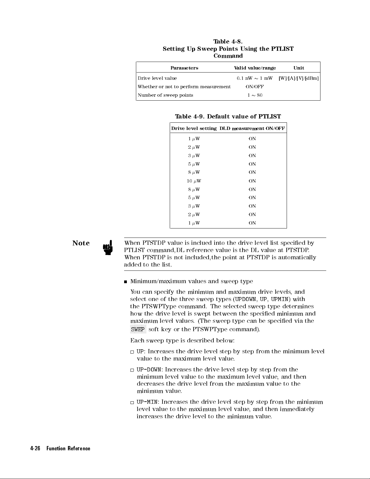
Drive
level value
Whether
Number
Setting
or
not
of
sweep
Up Sweep
P
arameters
to
perform measurement
points
T
able
4-9.
Default
Drive
level
setting
1
W
2
W
3
W
5
W
8
W ON
10
W
8
W
5
W
3
W
2
W
1
W
T
able 4-8.
P
oints
Command
V
alid
0.1 nW
value
DLD
measurement
Using
value/range
ON/OFF
1
of
ON
ON
ON
ON
ON
ON
ON
ON
ON
ON
the
PTLIST
1
mW
80
PTLIST
ON/OFF
Unit
[W]/[A]/[V]/[dBm]
Note
When
PTLIST
When
added
PTSTDP value
command,DL reference
PTSTDP
to
the
list.
is
not
Minimum/maximum
Y
ou
can
select
the
how
maximum
NN
one
PTSWPType
the
N
N
N
N
N
N
N
N
N
N
NN
SWEP
soft key or the PTSWPType command).
specify
drive
of
the
level
the
three
command.
level
values
is
inclued
into
value
included,the
values
and
minimum and
sweep types
The
is
swept between
. (The
sweep type
the
drive
is
the
DL
point
at
PTSTDP
sweep
type
maximum drive
(
UPDOWN
selected
sweep type
the specied
can be
level
list
value
is
,
UP
,
UPMIN
specied via
specied
at
automatically
levels,
determines
minimum and
Each sweep type is described below:
UP
: Increases the drive level step by step from the minimum level
value
to the maximum level value
UP-DOWN
:
Increases the drive level step by step from the
minimum level value
to the maximum level value
.
, and then
decreases the drive level from the maximum value to the
minimum value.
UP-MIN
: Increases the drive level step by step from the minimum
level value to the maximum level value, and then immediately
increases the drive level to the minimum value.
PTSTDP
and
)
with
by
.
the
4-26 Function Reference

Note
When
PTLIST
When
added
PTSTDP
value
command,DL
PTSTDP
to
the
is
list.
is
inclued
reference
not
included,the
into
value
the
point
drive level
is
the
DL
at
PTSTDP is
list specied
value at
automatically
by
PTSTDP.
Figure
The
following
values
When you
minimum/maximum values
internally predened series of level values (1, 2, 3,
50, 80, 100, 200, 300 . . . ). Thus
4-6.
Sweep
table
shows
and
sweep
Soft
type
K
eys/Commands
Minimum/Maximum
P
arameter
Minimum value
Maximum
Sweep
type
set
the
sweep
Type
for
value
points
how
each
T
and
to
of
able
Front
(soft
F
by
sweep
specify
the
4-10.
Used
V
alues
panel
key)
F
F
FF
FF
MIN
F
F
F
F
F
F
MAX
F
F
F
FF
FF
SWEP
specifying
F
F
F
FF
F
FF
F
F
the
front
to
and
PTMINP
PTMAXP
PTSWPType
type
,
minimum/maximum
panel
and
GPIB:
Specify
Sweep
the
Type
GPIB
ower
ower
the
the
E4916A
uses
5, 8, 10, 20, 30,
the E4915A/E4916A automatically
its
establishes all the individual drive levels between user-specied
minimum and maximum drive levels
.
The following table shows some examples:
Table 4-11. Drive Levels A
Maximum level
(user-specied)
Maximum level
(user-specied)
utomatically Established
Individual drive levels
(automatically established)
1nW 10 nW 1,2,3,5,8,10 [nW]
15 nW 250nW 15,20,30,50,80,100,200,250
[nW]
Function Reference 4-27

Note
The
sweep
N
N
N
N
N
N
N
N
N
N
N
N
NN
SWEP
to
the three
F
or more
to
Chapter 5
list
method
soft
key
on
sweep types
information on
\GPIB Command
the
is
available
front
(
how to
panel
Up
,
UpDown
Reference."
only
provides
,
use
DLD
via the
and
mode
GPIB although
a
List
option in
UpMin
).
via
the
GPIB
the
addition
,
refer
Measurement
parameter
Frequency
Crystal
impedance
Delta
Delta
Mode
mode
measurement
actual
mode
The
deviation
separately
following
panel.
Delta
Mode
Soft
key
Settings
F
F
F
F
F
F
F
1F
F
F
F
F
F
F
F
F
F
1CI
T
oset
the
reference
soft keys
High
, respectively
Q
Mode
for
drive
results
and
between
table shows
and
Soft
Measurement
DEV
PPM
DEV
%
(Measured
f
(Measured
(Measured
f
(Measured
level measurement
(frequency
percentage
and
.Also
resonance
T
K
how to
able
eys
4-12.
in
Drive
set up
Mode
Delta
value)
0
(reference
value)
0
(reference
value)
0
(reference
value)
0
(reference
frequency
and
CI
.
presents deviations
CI values)
,you
frequency
Delta
Level
in one
can turn
and
mode
Dependency
mode display
value)
[Hz]
value)
g
value)
[]
value)
g
values
,
use
in
of two
forms:
ON/OFF Delta
crystal impedance
through
the
form
/
(reference
/ (reference
the
N
N
N
N
N
NN
N
RefZ
N
N
N
N
N
N
value)
value)
and
front
[ppm]
[%]
N
N
N
N
N
NN
N
RefF
.
N
N
N
N
N
N
Note
4-28 Function Reference
High
Q
mode
is
intended
and
it
provides
N
N
NN
NN
NN
N
N
N
N
N
N
Hi-Q
the
Turning
(
Short
with
The
(
Short,Med
ON
,
Med
High
E4916A provides the three alternative measuring time settings
soft
High
,
Q
mode
,and
key.
and
longer
Q
Long
OFF
Long
other alternative settings with High Q mode ON; thus
settings in all. T
o control the measuring time via the GPIB
for
measuring
mode
causes
)
to
provide
.
) with High
use
when
time
the
QModeOFF
three
a
longer
the
DUT
has
.
T
o
enable
measuring
measurement time
, plus the three
a
High
high
Q
Q
mode
time
settings
,6
alternative
, issue the
value
,
use
than
,
MEASTime command followed by an integer from 1 to 6.
ALC Mode
ALC (Auto Level Control) mode, which can be turned ON via the
NNNNNNNNNN
N
ALC
soft key, provides level control based on the actual CI value to
actually apply the specied power to the DUT. When this mode is
OFF, level control is performed based on the user-specied nominal CI
value.

Note
T
o
enter
4
Nominal
CI
the
5
hard
nominal
key
N
N
N
N
N
N
N
N
N
NN
NN
NN
NN
NN
NN
N
N
N
N
N
N
N
N
N
N
CI
value
,use
the
Nominal
CI
N
soft
key
or
the
.
Output of
Measurement Results
LCD Screen
Fr/Fs and
Each DL
Dierence between
Dierence between
The maximum
GPIB
List
value
LED
Output
LED 1:
LED 2:
LED
F
or
in
the
this
Note
CI/Zs at
value
value of
that shows
at
the respective
the
Comparator result
Comparator result
3:
Result of
Comparator
chapter
.
each DL
the maximum
the maximum
CI
drive
level
sweep
for
for
1F
limit/1CI
function,
value
(power)
points
Fr
CI
limit
refer
and the
and
.
value
value
test
to
refer
minimum levels
the
minimum
values
,
Fr
at
the
reference
at
the
reference
(1FLimit
to
\Comparator
(FL)
and
levels
value
DL
DL
1CILimit
Function
of
Fr/Fs
of
CI/Zs
,
and
value
value
CI
"
Beep
Beep
Output
sound
is output
when a
DUT
has
passed
or
failed
the
comparator
test.
Handler
Refer to
Analog
Outputs DC signals whose level changes in proportion
frequency value
Interface
Appendix
OUT
T
erminal
.
C
\Handler
Interface
."
to the measured
Parameters and Their Settings
The parameters for controlling the output through the Analog
OUT terminal are accessible via their specic soft keys contained
in the System menu. (T
4
5+4
0
(blue)
AnalogOut
(System)
: Lets you turn ON/OFF the DC voltage output through
o access the System menu, press the
5
key).
the Analog OUT terminal.
NNNNNNNNNNNNNNNNNNNNNNNNNNNNN
Soft key:
AnalogOut
Hard key:|
GPIB command: ANLGOUTtfOFFjONj0j1
g
Function Reference 4-29

Settings
output
frequency
voltage
:
from
.
by
represented
soft
key,
you are
can
choose one
Soft key:
Hard
key:|
GPIB
command:
Lets
you
the
Analog
The
system
1
V
as
the
by
this
presented with
of
NN
NN
NN
NN
N
N
N
N
N
N
Settings
specify
OUT
increments
frequency
coecient.
them
and
N
N
N
N
N
N
N
N
N
N
N
N
ANLGDFDV
the
coecient
terminal
changes
When
two options:
enter
t
<
and
or
decrements
by
you
your
desired
value
>
of
the
the
measured
the amount
select
dFdv
value
,
ANLGREF
DC voltage
the
output
N
N
N
N
N
N
N
N
N
N
NN
Settings
the
and
REF
.
t
<
value
NN
NN
NN
NN
NN
NN
N
N
.
Y
ou
>
4-30 Function Reference

Evaporation Monitor
Mode (EM
Mode)
Purpose
and Principle
Applicable
A
ccess means:
Evaporation
during
Metal
a
deposition
deposition
frequency
resonator
Figure
and
under
E4916A,
another
specied
output
achieve
becomes
4-7
,
outputs
0
(or
then,
measurement.
value
to
the
ecient
Evaporation
because
preset
it
phase
Model: E4916A
front panel
Monitor
mode
process
is
used
of
a
crystal
lower
the
E4916A
preset
any
data
value you
moves
again,
I/O
port
and
accurate
Monitor
causes
at
the
a
certain
mode
E4916A
allows
of
during
resonator
as
deposition
monitors
to
the
specify as
its
focus to
When
it
outputs
controls
is
frequency
only
and GPIB
you
to
crystal
a
.
resonators
manufacturing to
The resonant
proceeds
the
phase
I/O
port
when the
you wish).
the next
the
measured
dierent
the
amount
metal
deposition.
also
referred
to
wait
for
,
control
metal
.
frequency of
.As
at a
specied frequency
measured phase
frequency f
phase
data
to
the
of
metal
to
as
\trap
the
phase
deposition
adjust the
described in
and
2
reaches the
I/O
port.
deposition
function"
to
match
a crystal
goes
performs
This
to
the
f
1
Figure 4-7. Trap function
Function Reference 4-31

Reverse monitor
P
arameters
and
mode
Their
When
resonator
becomes
monitor
grinding
direction, use
Settings
This
in
Evaporation
either
the
front
for the
CI
basis
ALC
mode
the
frequency
instead of
higher as
direction of
in the
same way
the
subsection
describes
Monitor
from
the
front
panel,
operation in
:
Determines the
for
level control
N
N
N
N
N
Soft
Hard
GPIB
:
Turns
,
Soft
Hard
GPIB
CI
key:
key:|
command:
ON/OFF
refer
to
N
NN
ALC
key:
key:|
command:
N
N
adjustment is
metal deposition,
grinding proceeds
Evaporation Monitor
NN
NN
NN
panel
ON
as metal
softkey
the
(EM)
or
the
parameters
mode
via
N
N
N
N
N
MAN
NN
N
DIR
turn
NN
advance.
nominal crystal
(with ALC
N
N
N
\ALC
N
N
N
N
N
N
NOMCI
ALC
ALC
Mode
tf
t
<
mode
" later
OFF
performed by
its resonance
.In
deposition. T
or the
N
N
.
These
the
N
N
N
N
EMDIR GPIB
GPIB,
softkey
impedance
mode
value
>
.(F
or more
in this
j
ON
j
0
j
1
this case
(EM) mode
that
control
parameters
or both.
to
display
OFF).
information
section).
g
grinding a
frequency
,by
reversing the
,you
oset
the monitor
command.
the
are accessible
To
softkeys
,
which
crystal
can control
operation
access from
required
is
used
as
on
ALC
the
Note
LVL
:
the
tip
Soft
Hard
GPIB
<
value
UNIT
:
from
Soft key:
Determines
of
the
key:
key:|
command:
>
Let
you
dBm,
jig.
N
N
N
N
N
N
NN
LVL
[MW
select the
W
ATT
N
NN
NN
N
N
N
UNIT
the
NN
N
j
UW
, AMP
N
N
N
N
N
N
POWEr
j
power level
t
NW
j
W
j
MA
unit of
,and
VOL
which
j
U
A
j
A
j
MV
the power
T
.
is
applied
j
UV
level
j
V
j
DBM]
N
(
to
N
N
N
N
N
LVL
N
N
N
the
NN
soft
device
key)
Hard key:|
GPIB command: POWEr
<
value>[MWjUWjNWjWjMAjUAjAjMVjUVjV
t
j
DBM]
The signal level specied with the E4915A indicates the power
actually applied to a resonator
the unit of the signal level, the specied level shows the
at the port of the E4916A instead of the power applied
. However
, when you
specify dBm as
signal level
to a resonator
With the E4915A, the output power level is xed at -5 dBm.
TIME
: Determines the measuring time, which can be one of three
alternative settings:
Short,Med
, and
Long
.
NNNNNNNNNNNNNN
Soft key:
TIME
at
.
4-32 Function Reference

Hard
key:
GPIB
command: MEASTime
HI
Q
:
Turns ON/OFF
Soft key:
Hard key:|
GPIB
command:
DIR
:
Lets
you
mode
depending
higher
Tout
DUT
CKT
or
Soft
key:
Hard
GPIB
:
Determines
to
Soft
key:
Hard
GPIB
:
Lets
lower
key:|
command:
reach
key:|
command:
you
measurement.
Measuring
Soft
Hard
GPIB
Circuit
key:
key:|
command:
PICKTtype
4
Meas
NN
NN
NN
NN
NN
NN
HI Q
specify
as
N
N
NN
N
N
N
N
N
N
N
Dir
the
N
N
N
N
N
N
N
N
N
N
N
N
Tout
specify
(F
or
N
N
N
N
N
NN
N
N
N
N
CKT
tf
PI41900A
5
Time
High Q
N
N
MEASTime
the
on
whether
the
frequency
EMDIR
the
length
specied
N
N
EMTMOUT
the
more
Type
").
CIRcuit
t
<
value
mode.
t
<
value
search
direction
the
measurement
adjustment
tf
UP
j
DOWN
of
time the
trap
frequency.
t
<
value
type
of
the
information,
tf
PI
j
PRObe
j
PI41901A
j
>
>
in
g
Trap function
>
circuit
refer
j
BRIdge
PI41902A
Evaporation
frequency
proceeds
to
be
to
\Selecting
.
used
g
g
Monitor
becomes
waits for
for
the
the
MAN
:
Determines
frequency
Soft
key:
Hard
key:|
GPIB
command:
PARA
:
Determines
which
Soft
Hard
can
key:
key:|
from
N
N
N
N
MAN
be
Fr
NN
N
N
PARA
whether
the
front
N
N
N
N
N
N
NN
NN
N
N
N
N
N
N
N
{OFF|ON}
EMMANmode
the
or
Fs
N
N
N
N
N
N
N
N
N
NN
NN
NN
NN
{FS|FR}
N
N
N
N
type
.
NN
NN
N
N
N
N
NN
N
N
to
panel.
N
N
N
N
N
N
NN
N
N
N
N
N
N
N
enable
N
of
the
N
N
GPIB command:|
PHAS
: Lets
you specify the target phase value
N
Soft key:
NNNNNNNNNNNNNNNNNNNNNNNN
PHAS <value>
NNNNNNNNNNNNN
Hard key:|
GPIB command:|
Ftgt
: Lets you specify the target frequency.
NNNNNNNNNNNNNNNNNNNNNNNNNNNNNNNNNNNNNN
Soft key:
Ftgt <value>
Hard key:|
GPIB command: EMLISTt<
fONj
OFFj0j1g,<value4
value1>,<value2>,<value3>,
>
the
tf
OFF
search
setting
j
ON
g
resonance
.
of the
trap
frequency
,
Flow
: Lets you specify the lowest trap frequency.
Function Reference 4-33

Soft
Hard
GPIB
f
Fmed
Soft
Hard
GPIB
f
Fhi
Soft
Hard
GPIB
f
N
NN
NN
NN
NN
Flow
key:
key:|
command: EMLIST
ON
j
OFF
j
0
j
1
g
,
:
Lets
you
specify
NN
N
N
N
N
N
N
N
Fmed
key:
key:|
command:
ON
j
OFF
j
0
j
1
g
,
:
Lets
you
specify
N
N
N
N
N
N
N
N
NN
Fhi
key:
key:|
command:
ON
j
OFF
j
0
j
1
g
,
NN
NN
N
N
N
N
N
N
N
N
N
<value>
<
value4
N
N
N
N
N
N
N
N
N
N
NN
NN
<value>
EMLIST
<
value4
NN
NN
NN
N
N
N
N
N
N
<value>
EMLIST
<
value4
N
N
NN
N
N
N
N
NN
NN
N
the
N
N
N
N
NN
NN
>
the
N
N
N
N
>
N
N
N
N
>
NN
N
N
N
NN
NN
NN
t
<
value1
2nd
N
N
N
N
t
<
value1
highest
t
<
value1
>
,
<
value2
trap
frequency
>
,
<
value2
trap frequency
>
,
<
value2
>
,
<
value3
>
,
.
>
,
<
value3
>
,
.
>
,
<
value3
>
,
Setting
Using
Measurement
Trap
P
oint
Functions
List (GPIB
T
o
specify
required
to
30
trap
The
trap
4
to
create
points
point
Only)
or
more
list
trap
a
trap
in
the
contains
points
point
trap
in
Evaporation
list
using
the
point
list.
the
following information
GPIB
Monitor
.
Y
ou can
for each
mode
, you
specify up
are
trap
point:
Frequency
Phase
Whether
for
value
to
turn ON/OFF
for
the
the
trap
trap
point
point
the
output
through
the
I/O
port
(handler
interface)
Data
to
be output
T
o
create a
trap point
information, refer
Chapter
ALC
ALC (A
NNNNNNNNNNN
ALC
5
and
Mode
uto Level Control) mode
soft key
, provides level control based on the actual CI value to
actually apply the specied power to the DUT
the
to the
sample
through the
list,
use
description of
program
I/O
port
(12
bit
length)
the
EMLIST
command.
the EMLIST
command
attached.
, which can be turned ON
. When this mode is
F
or
more
in
via the
OFF, level control is performed based on the user-specied nominal CI
value
.
Note
4-34 Function Reference
When you are working in Evaporation Monitor mode
NNNNNNNNNNNN
NNNNNNNNNNNNNNNNNNNN
Nominal CI
enables you to
verify the nominal CI value but, in this
, displaying
case, the CI value cannot be altered through the front panel.

Output
of
Measurement
Results
LCD
Screen/GPIB
Transition
point
that the
\#",\T",\F",\
started,#
trap
points
#
T
F
>
CI
value
Frequency
Time
required
Handler
Outputs
Analog
Interface
the
OUT
Measurement
the
Analog
through trap
DUT
>
"
are
is
displayed.
passed.
Measurement
yet.
Time
Measurement
specied
Finished
at
the
previous
for
the
between
data
dened
T
erminal
parameters
OUT
terminal
points
has
passed
displayed
A
out
next
trap
two
with
(indicates
on
a
at
the
number
of
point
point
correctly
trap
point
point
[Hz]
successive
the appropriate
whose
:
Fr
,
Fs,
the
real-time
bottom
#
diusplayed
does
not
go
through
[]
trap
value
can
F
a
frequency
basis)
of
LCD
shows
get
to
the
the
trap
points
GPIB
be
[ms]
command.
output
.
When
of
the
EM
number
trap
point
point
through
trap
is
of
Output
whose
the
P
arameters and
The
OUT
in
4
(blue)
voltage
:
level changes
dierence relative
parameters
terminal
the
System
5
+
4
0
AnalogOut
for
are
menu.
(System)
: Lets you turn ON/OFF the DC voltage output through
The
Analog
within
to the
OUT
the
nominal
Their Settings
controlling
accessible
(T
5
key).
o
access
via
range
the
their
the
terminal
of
0
frequency
output
specic
System
outputs
5
V
to
.
through
soft
menu,
a
+5V
the
keys
press
DV
,
indicating
Analog
contained
the
the Analog OUT terminal.
NNNNNNN
Soft key:
NNNNNNNNNNNNNNNNNNNNNN
AnalogOut
Hard key:|
GPIB command: ANLGOUT
Settings
: Lets you specify the coecient of the DC voltage
tf
OFFjONj0
j
1
g
output from the Analog OUT terminal and the measured
frequency. The system increments or decrements the output
voltage by 1 V as the frequency changes by the amount
represented by this coecient. When you select the
soft key, you are presented with two options:
dFdv
NNNNNNNNNNNNNNNNNNNNNNNNNN
Settings
and
can choose one of them and enter your desired value.
NNNNNNNNNNNNNNNNNNNNNNNNNN
Soft key:
Settings
signal
REF
.You
Function Reference 4-35

Hard
key:|
GPIB
command: ANLGDFDV
t
<
value
>
, ANLGREF
t
<
value
>
4-36 Function Reference

Filter Measurement
Mode (Flt
Mode)
Purpose
and Principle
Applicable
A
ccess means:
Filter
measurement
loss
of
a
either
loss
loss
constant
by
measuring
by
measuring
Model: E4916A
front panel
crystal
lter
or
mode
(band-pass
minimum
the
loss
the
loss
only
and GPIB
is
intended
lter).
loss
.
at
the nominal
at
the peak
for
determining
In
this
The E4916A
frequency,
frequency.
the
insertion
mode
,you
can measure
determines the
and the
constant
minimum
P
arameters and
Figure
4-8.
Filter measurement
characteristic parameters:
Constant
X-axial
Their Settings
This
of
the
parameters are accessible via either a hard key or a soft key
FREQ
Soft key:
Hard key:
GPIB command: NOMFreq
RNG
Soft key:
Hard key:
GPIB command: SRCHRanget<
Constant
or
dB
subsection describes
E4916A
loss
minimum
band
width
in
Filter
and minimum
mode determines
loss
values
(1FL,
the parameters
measurement
loss
the
values
1FR,
and
that control
mode
(Flt
: Lets you specify the nominal frequency value
NNNNNNNNNNNNNN
FREQ
5
4
Freq
: Search range
t<value
. Specify the resonance point search range
>
NNNNNNNNNNN
RNG
4
5
Freq
value
>
of
the
following
BW;
BW=1FL+1FR)
the behavior
mode).
These
.
, or both.
.
LOSS
: Provides two alternative options:
Const
for the constant loss,or
Const
Min
for the minimum loss.
and
Min
. Select
Function Reference 4-37

Soft
key:
Hard
key:|
GPIB
command: FL
xdB
: Specify
Soft key:
Hard
key:|
GPIB
command:
LVL
:
Lets
Soft
key:
Hard key:
GPIB
command:
TIME
:
Lets you
alternative
Soft
key:
Hard
key:
GPIB
command: MEASTime
HI
Q
:
Lets you
High
Qmode
Soft
key:
Hard
key:|
GPIB
command:
N
NN
NN
NN
NN
NN
LOSS
the
NN
NN
N
N
N
N
N
N
xdB
you
specify
N
N
N
N
N
N
N
N
N
N
LVL
4
Level
specify the
settings:
N
N
N
N
N
N
N
N
N
N
TIME
4
Meas
turn ON/OFF
, refer
N
N
N
N
N
N
N
N
N
N
HI
NN
N
TMODE
down
N
FL
TDB
the
N
5
POWEr
Short
N
N
N
N
5
Time
to
N
N
N
N
Q
MEASTime
tf
value
for
t
<
value
signal
t
<
value
measuring time
,
Med
t
High
\High
Q
Mode
t
CONST
lter
>
level.
>
,
and
<
value
Q
mode
"
<
value
ant
band
Long
>
later
>
j
MINimam
width
by
selecting
.
.
(F
or
more
in
this
g
one
information
section).
of
three
on
Note
Measurement Functions
T
o
set the
4
Select
entry
Some
other
choose
chosen
the
4
When
next
value
5
key
next
mode
.
parameters
parameters
an
option,
the
desired
5
key
Enter
no
soft
pair
of
soft keys
to
key
of
to
the
accept
accept
use
put
is
a
option
parameter
soft
key
your
only
the
4
*
or
the
new
selected
by pressing
accessible
to
put
manually
one
of
5
or
)
entered
setting
yet,
you
the
4
(
the
the
+
the
into
can
4
*
via
a
soft
LCD
screen
entered
presented
5
key
.
When
appropriate
eect.
access
5
or
4
)
(
value
options
the
5
+
key
you
,
press
into
data
while
the
.
T
o
have
value
,
press
previous or
key
.
High Q Mode
High Q mode is intended
and it provides longer measuring time
N
NNNNNNNNNNNNN
the
Hi-Q
soft key
.
for use when the DUT has a high Q value
.T
o enable High Q mode
,use
Turning ON High Q mode causes the three measuring time settings
(
Short,Med
,and
Long
) to provide a longer measurement time than
with High Q mode OFF.
the
,
4-38 Function Reference

Note
The
E4916A
(
Short
,
Med
other
alternative
settings
in
MEASTime
provides
,
and
Long
settings
all.
T
o
control
command
the
three
) with
with
the
followed
alternative
High Q
High
Mode OFF
Q
mode
measuring time
by an
integer from
measuring
, plus
ON; thus
via the
1to
time settings
the three
,6
alternative
GPIB,
issue the
6.
Output
of
Measurement Results
Note
LCD
Screen/GPIB
Constant
X-axial
In
Filter
measurement
even when
key
.
loss
dB
band
you turn
or
minimum
width
values
mode
OFF the
loss
,the
status
and
(F
L
soft keys
display
Fr)
remain displayed
using
the
4
(blue)
on
screen
5
+
4
1
(Status)
5
Function Reference 4-39

LCR Measurement
Mode
Purpose
Caution
and
Principle
Applicable
A
ccess means:
Make
sure
probe
.
F
or
In
LCR
measurement
Z,
which
equivalent
Model: E4916A
front panel
that
the
more
information,
is a
vector value
circuits:
test
signal
mode
only (requires
and GPIB
level
refer
,
the
E4916A measures
,and
gives the
is
0
dBm
\EMC"
Options 001/010)
or
lower
in
Chapter
a DUT's
result
using
when
9.
the
using
impedance,
following
the
4-40 Function Reference
Figure 4-9. Relationship between Measurement P
In Figure 4-9,
Ls :
Equivalent series
Cp :
inductance
Lp :
Equivalent parallel
inductance
Q:
D: Dissipation Factor
Cs : Equivalent series
capacitance
Measurement parameters for LCR measurement mode include the
following:
arameters
Equivalent parallel
capacitance
Quality factor

Primary
P
aremeters
Z,Y
,R,G,Cp
,Cs
,Lp
,Ls
P
arameters
and
Their
where
Z
:
Y
:
R
:
G
:
Cp:Equivalent
Secondary
:
X
:
B
: Susceptance
D
:
Q
:
Settings
Secondary
,
Absolute
value
impedance
Absolute
value
admittance
Resistance
Conductance
capacitance
P
arameters
Phase
angle
Reactance
Dissipation
Quality
factor
of
of
parallel
factor
Parameterz,
Cs:Equivalent
Lp:Equivalent
Ls:Equivalent
G
Rp
Rs:Equivalent
y,X,B
,D,Q,G,Rp
capacitance
inductance
inductance
:
Conductance
:
Equivalent
resistance
,Rs
series
parallel
series
parallel
series
resistance
Deviation
Lets
dierence
key
A
vailable
1ABS
M
easur
1%
you
is
also
mode
edV
mode
(1)
measurement
select
the
between
used
deviation
al
ue
0
deviation
the
measured
for
entering
modes include
Displays
value
the
and
calculated
R
ef
er
enceV al
Displays
the
measurement
value
the
deviation
the following:
dierence
a
reference
by
ue
dierence
mode
and
a
reference
reference
between the
value
.The
between
which
value
measured
value is
the
measurement
value and the reference value as a percentage of
the
M easuredV alue
Ref erenceV al
O
reference value
0
Ref
erenceV alue
ue
Turns the deviation
. The value is calculated by
2
100
measurement mode OFF
(default)
Measuring time
Let you set measuring time mode: SHORT, MED (Medium), or
LONG. A longer measurement time produces a more accurate
measurement result. The default setting is MED (Medium).
displays
value
.
.
.
the
This
Averaging
Function Reference 4-41

Lets
you set
can
be set
T
est frequency
Lets
MHz
The
owing
DUT
.
you set
and 180
Level
through
from
Monitor
the measurement
1
to
256.
The
the
test
frequency
MHz.
function
the
DUT
monitors
and
averaging
default
value
the
actual
rate
setting
within
the
actual
signal
.
The
is
1.
the
signal
voltage
averaging
range
current
between
across
rate
1
the
4-42 Function Reference
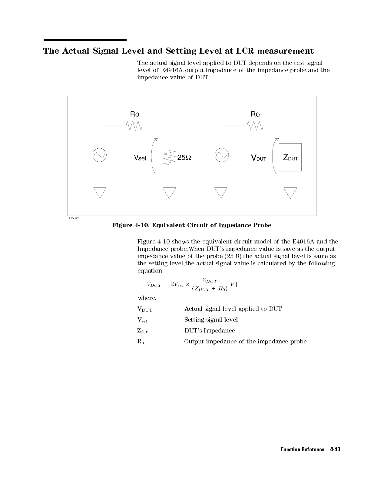
The A
ctual Signal
Level and
Setting Level
at
LCR
measurement
Figure
The actual
level of
signal level
E4916A,output impedance
impedance value
4-10.
Equivalent
applied to
of DUT
Circuit
.
of
Impedance
DUT depends
of the
impedance probe
Probe
on the
test signal
,and the
Figure
4-10
Impedance
impedance
the
setting
equation.
V
=
D
U
T
where
,
V
DUT
V
set
Z
dut
R
0
shows
probe
value
level,the
2
V
set
.When
2
A
Setting
the
equivalent
DUT's
of
the
probe
actual
Z
D
U
(
+
Z
D
U
T
ctual signal
signal level
circuit
impedance
(25
),the
signal
T
value
[
V
]
)
R
0
level applied
model
value
actual
is
calculated
to DUT
DUT's Impedance
Output impedance of the impedance probe
of
the
is
save
signal
E4916A
as
level
by
the
and
the
output
is
same
following
the
as
Function Reference 4-43

Calibration and
Fixture Compensation
This section
facilities of
with both
provides descriptive
the E4915A/E4916A:
E4915A and
function (available
The Calibration
function allows
characteristics while
xture or
function is
to measure
Calibrating the
measured by
each of
Open
with
Short
Loaded
a
The
analyze
impedance
shown
C,
and
is
a
measuring
states
impedance probe
particularly useful
the
putting
the
following
0
the
a
DUT
.
0
the
0
the state
standard
DUT (a
Calibration
a
measuring
probe)
in
Figure
D
that
linear
passive
a
known
.
CI
characteristics
E4915A/E4916A
state
state
function
between
4-11
form
circuit,
E4916A) and
with the
E4916A only).
eliminating the
connected to
when you
the
xture
three
states:
in
in
which
which
the
the
in which
device that
uses
a
circuit
(such
the
,
this
model
an
F
matrix.
the
four
device
in
each
information on
the Calibration
the Fixture
you to
measure
inuence of
the
use
a
of
a
DUT
.
requires
test
xture
xture
the xture
provides a
2-terminal
as
terminal
or
or
a
network
the
calibration
probe
probe
or probe
standard condition).
pair
E4915A/E4916A
is
represented
If
the
2-terminal
parameters
of
the
Open,
the error
function (available
Compensation
the
CI
or
LCR
an
Agilent
DUT
.
The
Calibration
network
test
data
or
the
probe
is
not
connected
is
short-circuited.
is
connected
circuit
can
model
test
xture
and
the
by
parameters
pair
be
determined
Short,
DUT
circuit
and
correction
network
xture
tip
into
with
to
or
.
As
A,
B
network
by
Loaded
,
Note
4-44 Function Reference
Figure 4-11. Calibration Model
Re calibration and compensation are required when the measurement
mode or the
data will be lost
measurement circuit is changed. The privious calibration
when re-calibration is performed.

P
erforming
the
Calibration
and
Compensation
This
subsection
Compensation
T
able
State
shows
how
measurements
4-13.
A
of
connection
Measurements
to
perform
.
ccessing
Front
panel
the
Calibration Function
(hard
each
key)
of
the
Calibration
GPIB
command
and
Calibration
Standard
V
alues
The
factory-preset
and
There
standard values
the standard
before you
A
State
standard
Option
are
occasions
OPEN
SHORT
LO
AD
THRU
ccessing
of
connection
the
OPEN
SHORT
LO
AD
values
the
assuming
001
Impedance
when
.
If
this
values
for
calibrate the
5
4
+
(blue)
4
(blue)
4
(blue)
4
(blue)
Fixture
Front
4
(blue)
4
(blue)
4
(blue)
4
4 (Open)
5
+
4
5
(Short)
5
+
4
6
(Load)
5
+
4
3 (Thru)
T
able
4-14.
Compensation
panel
(hard
5
+
4
7
(Open)
5
+
4
8
(Short)
5
+
4
9 (Load)
E4915A/E4916A
the
use
of
the 41900A
Probe
.
you
need
to use
is
the
case
,
supply
each
of
the
Open,
E4915A/E4916A.
5
5
CALibration
5
5
CALibration
CALibration
t
t
t
THRUCAL
OPEN
SHORT
LOAD
Function
key)
GPIB
5
COMPENsation
5
COMPENsation
5
COMPENsation
uses for
command
calibration
Network
t
t
t
OPEN
OPEN
LOAD
T
non-default calibration
the
E4915A/E4916A
Short,
and
Loaded
are
est
states
Fixture
with
The calibration
using such
standard values
a 2-element
model
for
as
the
shown
E4915A/E4916A
in
Figure
4-12
.
are
dened
Figure 4-12. Calibration standard model
You can set the calibration standard values for each of the measuring
circuit types supported by the E4915A/E4916A that is,anetwork
test xture, impedance probe, and reection bridge.For THRU
Function Reference 4-45

calibration,
Calibration
only
.
The
E4915A/E4916A retains
with
the power
dierent
The
following
assume
001
Impedance
you need
function requires
o.
values or
table
the
use
of
Probe:
T
able
not set
The
preset
shows
the
419002A
4-15.
calibration
the
calibration
the
calibration
current
settings
E4915A/E4916A
the
factory-preset
Network
Calibration
standard
data
standard
are
in
.
standard
T
est
Standard
values
for
the
eect
Fixture
V
alues
because
Thru
values
until
values
and
state
even
you
that
Option
the
input
Fixture
Compensation
OPEN SHORT LO
G C R L R L
The
4
(blue)
0
E4916A
In
errors
the
the
eliminate
test
useful
xture
The
Loaded
Calibration
always
Option 001
Impedance Probe
41900A 0S0.1pF1
41901A 0S 0.1pF 1
41902A 0S0.1pF1
standard values
5
+
4
0
(System)
5
key or
can be
CALSTD
Only
addition
419002A
E4916A oers
conguration. This
Fixture
to
the
caused
by
the inuence
when you
with
APC-7
Compensation
states
as
function, the
require
Calibration
the
intervention
Network T
an additional
of a
function, called
add your
terminals
does
the
Fixture Compensation
the
compensation value
0S 310fF 0 0H 50 5.75 nH
0.6nH5014
0.1 nH 50 3.4 nH
3nH
N
set
from
function,
est
Fixture
measuring
N
N
N
N
N
NN
NN
CAL
and
COMPENSTD
which
of
a
measuring
or
Option
error-correction
circuit
N
N
and
N
N
N
N
NN
COMP
commands
you
001
facility
added
Fixture Compensation,
custom measuring
to
accommodate
function
Calibration
recognizes
function.
circuit
the
the
However
function
for
the
loaded
5018.8
NN
N
N
N
N
N
softkeys under
can
use to
function
Impedance
intended
to
the
or
an
16099A
Open,
,
does
state;
the compensation values in one of the following two combinations:
states:
AD
nH
nH
via
correct
such as
original
Agilent
input
Short,
unlike
not
it
GPIB
Probe
to
is
test
probe
and
the
uses
.
,
.
4-46 Function Reference
Open and Short states
Open, Short, and Load states
These two dierent
following subsections
combinations are described in detail in the
.
 Loading...