


WLAN Guide
PSA Series Spectrum Analyzers
Option 217
This manual provides documentation for the following instruments:
Spectrum Analyzers:
E4440A (3 Hz – 26.5 GHz)
E4443A (3 Hz – 6.7 GHz)
E4445A (3 Hz – 13.2 GHz)
Manufacturing Part Number: E4440-90280
Printed in USA
June 2005
© Copyright 1999 - 2005 Agilent Technologies, Inc.

The information contained in this document is subject to change
without notice.
Agilent T echnologies makes no warranty of any kind with regard to this
material, including but not limited to, the implied warranties of
merchantability and fitness for a particular purpose. Agilent
Technologies shall not be liable for errors contained herein or for
incidental or consequential damages in connection with the furnishing,
performance, or use of this material.
2

Contents
1. Introduction
What Does the Agilent PSA Option 217 Do? . . . . . . . . . . . . . . . . . . . . . . . . . . . . . . . . . . . . . . 24
Installing Optional Measurement Personalities . . . . . . . . . . . . . . . . . . . . . . . . . . . . . . . . . . . 26
Do You Have Enough Memory to Load All Your Personality Options? . . . . . . . . . . . . . . . . 26
How to Predict Your Memory Requirements . . . . . . . . . . . . . . . . . . . . . . . . . . . . . . . . . . . . . 28
Loading an Optional Measurement Personality . . . . . . . . . . . . . . . . . . . . . . . . . . . . . . . . . . 30
Obtaining and Installing a License Key . . . . . . . . . . . . . . . . . . . . . . . . . . . . . . . . . . . . . . . . 30
Viewing a License Key . . . . . . . . . . . . . . . . . . . . . . . . . . . . . . . . . . . . . . . . . . . . . . . . . . . . . . 31
Using the Delete License Key. . . . . . . . . . . . . . . . . . . . . . . . . . . . . . . . . . . . . . . . . . . . . . . . . 31
Performing a Security Erase on PSA Series Spectrum Analyzers. . . . . . . . . . . . . . . . . . . . 32
Ordering Optional Measurement Personalities . . . . . . . . . . . . . . . . . . . . . . . . . . . . . . . . . . 33
2. Making Measurements
Introduction . . . . . . . . . . . . . . . . . . . . . . . . . . . . . . . . . . . . . . . . . . . . . . . . . . . . . . . . . . . . . . . . 36
Setting Up Test Equipment and DUT. . . . . . . . . . . . . . . . . . . . . . . . . . . . . . . . . . . . . . . . . . . . 38
The 3 Steps to Set Up and Make Measurements . . . . . . . . . . . . . . . . . . . . . . . . . . . . . . . . . . . 39
Setting Mode-Level Parameters . . . . . . . . . . . . . . . . . . . . . . . . . . . . . . . . . . . . . . . . . . . . . . . . 40
Selecting a WLAN Standard . . . . . . . . . . . . . . . . . . . . . . . . . . . . . . . . . . . . . . . . . . . . . . . . . 40
Setting Frequency Parameters. . . . . . . . . . . . . . . . . . . . . . . . . . . . . . . . . . . . . . . . . . . . . . . . 40
Adjusting Input Parameters. . . . . . . . . . . . . . . . . . . . . . . . . . . . . . . . . . . . . . . . . . . . . . . . . . 41
Setting Trigger Parameters (for burst signals) . . . . . . . . . . . . . . . . . . . . . . . . . . . . . . . . . . . 41
Setting Demod Parameters . . . . . . . . . . . . . . . . . . . . . . . . . . . . . . . . . . . . . . . . . . . . . . . . . . 42
Using Instrument Mode and Measurement Presets. . . . . . . . . . . . . . . . . . . . . . . . . . . . . . . 43
Making One Button Measurements . . . . . . . . . . . . . . . . . . . . . . . . . . . . . . . . . . . . . . . . . . . . . 44
One Button Measurement Examples . . . . . . . . . . . . . . . . . . . . . . . . . . . . . . . . . . . . . . . . . . . . 45
Transmit Power Measurement. . . . . . . . . . . . . . . . . . . . . . . . . . . . . . . . . . . . . . . . . . . . . . . . 45
Transmit Spectrum Mask Measurement. . . . . . . . . . . . . . . . . . . . . . . . . . . . . . . . . . . . . . . . 47
Power vs. Time Measurement . . . . . . . . . . . . . . . . . . . . . . . . . . . . . . . . . . . . . . . . . . . . . . . . 50
Spectral Flatness Measurement. . . . . . . . . . . . . . . . . . . . . . . . . . . . . . . . . . . . . . . . . . . . . . . 52
Modulation Accuracy Measurements. . . . . . . . . . . . . . . . . . . . . . . . . . . . . . . . . . . . . . . . . . . 53
Power Stat CCDF Measurements . . . . . . . . . . . . . . . . . . . . . . . . . . . . . . . . . . . . . . . . . . . . . 60
Spectrum and Waveform Measurements. . . . . . . . . . . . . . . . . . . . . . . . . . . . . . . . . . . . . . . . 63
Using Basic Mode . . . . . . . . . . . . . . . . . . . . . . . . . . . . . . . . . . . . . . . . . . . . . . . . . . . . . . . . . . . 64
Basic Mode in E4406A VSA Series Transmitter Testers . . . . . . . . . . . . . . . . . . . . . . . . . . . 64
Basic Mode in PSA Series Spectrum Analyzers . . . . . . . . . . . . . . . . . . . . . . . . . . . . . . . . . . 64
Interpreting Error Codes . . . . . . . . . . . . . . . . . . . . . . . . . . . . . . . . . . . . . . . . . . . . . . . . . . . . . . 65
T a ble of Contents
3. Front-Panel Key and SCPI Command Re ference
Instrument Front Panel Highlights . . . . . . . . . . . . . . . . . . . . . . . . . . . . . . . . . . . . . . . . . . . . . 68
Programming Command Compatibility
Across Model Numbers and Across Modes . . . . . . . . . . . . . . . . . . . . . . . . . . . . . . . . . . . . . . . . 70
Across PSA Modes: Command Subsystem Similarities . . . . . . . . . . . . . . . . . . . . . . . . . . . . 70
Across PSA Modes: Specific Command Differences . . . . . . . . . . . . . . . . . . . . . . . . . . . . . . . 72
Using Applications in PSA Series vs. VSA E4406A . . . . . . . . . . . . . . . . . . . . . . . . . . . . . . . 73
Front-Panel Keys . . . . . . . . . . . . . . . . . . . . . . . . . . . . . . . . . . . . . . . . . . . . . . . . . . . . . . . . . . . . 75
FREQUENCY Channel . . . . . . . . . . . . . . . . . . . . . . . . . . . . . . . . . . . . . . . . . . . . . . . . . . . . . 75
Meas Control . . . . . . . . . . . . . . . . . . . . . . . . . . . . . . . . . . . . . . . . . . . . . . . . . . . . . . . . . . . . . . 77
Mode. . . . . . . . . . . . . . . . . . . . . . . . . . . . . . . . . . . . . . . . . . . . . . . . . . . . . . . . . . . . . . . . . . . . . 79
3

Contents
Table of Contents
4. Concepts
Mode Setup. . . . . . . . . . . . . . . . . . . . . . . . . . . . . . . . . . . . . . . . . . . . . . . . . . . . . . . . . . . . . . . .80
Measure . . . . . . . . . . . . . . . . . . . . . . . . . . . . . . . . . . . . . . . . . . . . . . . . . . . . . . . . . . . . . . . . . . . .85
Command Interactions: MEASure, CONFigure, FETCh, INITiate and READ . . . . . . . . . .85
Transmit Power . . . . . . . . . . . . . . . . . . . . . . . . . . . . . . . . . . . . . . . . . . . . . . . . . . . . . . . . . . . .88
Modulation Accuracy . . . . . . . . . . . . . . . . . . . . . . . . . . . . . . . . . . . . . . . . . . . . . . . . . . . . . . . .89
Transmit Spectrum Mask . . . . . . . . . . . . . . . . . . . . . . . . . . . . . . . . . . . . . . . . . . . . . . . . . . . .94
Power vs. Time . . . . . . . . . . . . . . . . . . . . . . . . . . . . . . . . . . . . . . . . . . . . . . . . . . . . . . . . . . . .100
Power Stat CCDF. . . . . . . . . . . . . . . . . . . . . . . . . . . . . . . . . . . . . . . . . . . . . . . . . . . . . . . . . .101
Transmit Spectral Flatness . . . . . . . . . . . . . . . . . . . . . . . . . . . . . . . . . . . . . . . . . . . . . . . . . .103
Spectrum (Freq Domain) . . . . . . . . . . . . . . . . . . . . . . . . . . . . . . . . . . . . . . . . . . . . . . . . . . . .104
Waveform (Time Domain) . . . . . . . . . . . . . . . . . . . . . . . . . . . . . . . . . . . . . . . . . . . . . . . . . . .104
Measurement Keys . . . . . . . . . . . . . . . . . . . . . . . . . . . . . . . . . . . . . . . . . . . . . . . . . . . . . . . . . .105
Transmit Power Measurement . . . . . . . . . . . . . . . . . . . . . . . . . . . . . . . . . . . . . . . . . . . . . . .105
Transmit Spectrum Mask Measurement . . . . . . . . . . . . . . . . . . . . . . . . . . . . . . . . . . . . . . .118
Power vs. Time Measurement . . . . . . . . . . . . . . . . . . . . . . . . . . . . . . . . . . . . . . . . . . . . . . . .137
Spectral Flatness Measurement . . . . . . . . . . . . . . . . . . . . . . . . . . . . . . . . . . . . . . . . . . . . . .148
Modulation Accuracy Measurement . . . . . . . . . . . . . . . . . . . . . . . . . . . . . . . . . . . . . . . . . . .160
Power Stat CCDF Measurement . . . . . . . . . . . . . . . . . . . . . . . . . . . . . . . . . . . . . . . . . . . . .200
Introduction . . . . . . . . . . . . . . . . . . . . . . . . . . . . . . . . . . . . . . . . . . . . . . . . . . . . . . . . . . . . . . . .210
What Is the WLAN Communication System? . . . . . . . . . . . . . . . . . . . . . . . . . . . . . . . . . . . . .211
What is a WLAN device?. . . . . . . . . . . . . . . . . . . . . . . . . . . . . . . . . . . . . . . . . . . . . . . . . . . . . .213
Digital Modulation Format Standards. . . . . . . . . . . . . . . . . . . . . . . . . . . . . . . . . . . . . . . . . . .215
Introduction . . . . . . . . . . . . . . . . . . . . . . . . . . . . . . . . . . . . . . . . . . . . . . . . . . . . . . . . . . . . . .215
Modulation Formats and WLAN standards . . . . . . . . . . . . . . . . . . . . . . . . . . . . . . . . . . . . .215
Phase Shift Keying (PSK) Concepts . . . . . . . . . . . . . . . . . . . . . . . . . . . . . . . . . . . . . . . . . . .216
Quadrature Amplitude Modulation (QAM) Concepts . . . . . . . . . . . . . . . . . . . . . . . . . . . . .220
Spread Spectrum Concepts. . . . . . . . . . . . . . . . . . . . . . . . . . . . . . . . . . . . . . . . . . . . . . . . . . . .223
Direct Sequence Spread Spectrum (DSSS) Concepts. . . . . . . . . . . . . . . . . . . . . . . . . . . . . .223
Complementary Code Keying (CCK) Concepts. . . . . . . . . . . . . . . . . . . . . . . . . . . . . . . . . . .223
Packet Binary Convolutional Coding (PBCC) Concepts . . . . . . . . . . . . . . . . . . . . . . . . . . .224
Orthogonal Frequency Division Multiplexing (OFDM) Concepts. . . . . . . . . . . . . . . . . . . . . .225
WLAN Standards . . . . . . . . . . . . . . . . . . . . . . . . . . . . . . . . . . . . . . . . . . . . . . . . . . . . . . . . . . .226
Overview. . . . . . . . . . . . . . . . . . . . . . . . . . . . . . . . . . . . . . . . . . . . . . . . . . . . . . . . . . . . . . . . .226
802.11b . . . . . . . . . . . . . . . . . . . . . . . . . . . . . . . . . . . . . . . . . . . . . . . . . . . . . . . . . . . . . . . . . .226
802.11a . . . . . . . . . . . . . . . . . . . . . . . . . . . . . . . . . . . . . . . . . . . . . . . . . . . . . . . . . . . . . . . . . .228
802.11g . . . . . . . . . . . . . . . . . . . . . . . . . . . . . . . . . . . . . . . . . . . . . . . . . . . . . . . . . . . . . . . . . .231
WLAN Measurement Concepts. . . . . . . . . . . . . . . . . . . . . . . . . . . . . . . . . . . . . . . . . . . . . . . . .233
Transmit Power Measurement Concepts . . . . . . . . . . . . . . . . . . . . . . . . . . . . . . . . . . . . . . .233
Transmit Spectrum Mask Measurement Concepts . . . . . . . . . . . . . . . . . . . . . . . . . . . . . . .234
Power vs. Time Measurement Concepts . . . . . . . . . . . . . . . . . . . . . . . . . . . . . . . . . . . . . . . .235
Spectral Flatness Measurement Concepts . . . . . . . . . . . . . . . . . . . . . . . . . . . . . . . . . . . . . .236
Modulation Accuracy Measurement Concepts . . . . . . . . . . . . . . . . . . . . . . . . . . . . . . . . . . .237
Power Stat CCDF Measurement Concepts. . . . . . . . . . . . . . . . . . . . . . . . . . . . . . . . . . . . . .240
Other Sources of Measurement Information . . . . . . . . . . . . . . . . . . . . . . . . . . . . . . . . . . . . . .243
Instrument Updates at www.agilent.com. . . . . . . . . . . . . . . . . . . . . . . . . . . . . . . . . . . . . . .243
References . . . . . . . . . . . . . . . . . . . . . . . . . . . . . . . . . . . . . . . . . . . . . . . . . . . . . . . . . . . . . . . . .244
4

Contents
5. Menu Maps
WLAN Measurement Key Flow. . . . . . . . . . . . . . . . . . . . . . . . . . . . . . . . . . . . . . . . . . . . . . . . 246
Directions for Use . . . . . . . . . . . . . . . . . . . . . . . . . . . . . . . . . . . . . . . . . . . . . . . . . . . . . . . . . 248
T a ble of Contents
5

Contents
Table of Contents
6

List of Commands
:CALCulate:CCDF:STORe:REFerence . . . . . . . . . . . . . . . . . . . . . . . . . . . . . . . . . . . . . . . . . . . . . . . 201
:CALCulate:EVM:LIMit:CARRiersuppression <real> . . . . . . . . . . . . . . . . . . . . . . . . . . . . . . . . . . . 200
:CALCulate:EVM:LIMit:CARRiersuppression? . . . . . . . . . . . . . . . . . . . . . . . . . . . . . . . . . . . . . . . . 200
:CALCulate:EVM:LIMit:CHIPs1000 <real> . . . . . . . . . . . . . . . . . . . . . . . . . . . . . . . . . . . . . . . . . . . 200
:CALCulate:EVM:LIMit:CHIPs1000? . . . . . . . . . . . . . . . . . . . . . . . . . . . . . . . . . . . . . . . . . . . . . . . . 200
:CALCulate:EVM:LIMit:CLKerror <real> . . . . . . . . . . . . . . . . . . . . . . . . . . . . . . . . . . . . . . . . . . . . 194
:CALCulate:EVM:LIMit:CLKerror? . . . . . . . . . . . . . . . . . . . . . . . . . . . . . . . . . . . . . . . . . . . . . . . . . 194
:CALCulate:EVM:LIMit:FERRor <freq>. . . . . . . . . . . . . . . . . . . . . . . . . . . . . . . . . . . . . . . . . . . . . . 193
:CALCulate:EVM:LIMit:FERRor?. . . . . . . . . . . . . . . . . . . . . . . . . . . . . . . . . . . . . . . . . . . . . . . . . . . 193
:CALCulate:EVM:LIMit:IQOFfset <real>. . . . . . . . . . . . . . . . . . . . . . . . . . . . . . . . . . . . . . . . . . . . . 195
List of Commands
:CALCulate:EVM:LIMit:IQOFfset? . . . . . . . . . . . . . . . . . . . . . . . . . . . . . . . . . . . . . . . . . . . . . . . . . . 195
:CALCulate:EVM:LIMit:RMS <real> . . . . . . . . . . . . . . . . . . . . . . . . . . . . . . . . . . . . . . . . . . . . . . . . 199
:CALCulate:EVM:LIMit:RMS:M12 <real> . . . . . . . . . . . . . . . . . . . . . . . . . . . . . . . . . . . . . . . . . . . . 190
:CALCulate:EVM:LIMit:RMS:M12? . . . . . . . . . . . . . . . . . . . . . . . . . . . . . . . . . . . . . . . . . . . . . . . . . 190
:CALCulate:EVM:LIMit:RMS:M18 <real> . . . . . . . . . . . . . . . . . . . . . . . . . . . . . . . . . . . . . . . . . . . . 190
:CALCulate:EVM:LIMit:RMS:M18? . . . . . . . . . . . . . . . . . . . . . . . . . . . . . . . . . . . . . . . . . . . . . . . . . 190
:CALCulate:EVM:LIMit:RMS:M24 <real> . . . . . . . . . . . . . . . . . . . . . . . . . . . . . . . . . . . . . . . . . . . . 191
:CALCulate:EVM:LIMit:RMS:M24? . . . . . . . . . . . . . . . . . . . . . . . . . . . . . . . . . . . . . . . . . . . . . . . . . 191
:CALCulate:EVM:LIMit:RMS:M36 <real> . . . . . . . . . . . . . . . . . . . . . . . . . . . . . . . . . . . . . . . . . . . . 191
:CALCulate:EVM:LIMit:RMS:M36? . . . . . . . . . . . . . . . . . . . . . . . . . . . . . . . . . . . . . . . . . . . . . . . . . 191
:CALCulate:EVM:LIMit:RMS:M48 <real> . . . . . . . . . . . . . . . . . . . . . . . . . . . . . . . . . . . . . . . . . . . . 192
:CALCulate:EVM:LIMit:RMS:M48? . . . . . . . . . . . . . . . . . . . . . . . . . . . . . . . . . . . . . . . . . . . . . . . . . 192
:CALCulate:EVM:LIMit:RMS:M54 <real> . . . . . . . . . . . . . . . . . . . . . . . . . . . . . . . . . . . . . . . . . . . . 192
:CALCulate:EVM:LIMit:RMS:M54? . . . . . . . . . . . . . . . . . . . . . . . . . . . . . . . . . . . . . . . . . . . . . . . . . 192
:CALCulate:EVM:LIMit:RMS:M6 <real> . . . . . . . . . . . . . . . . . . . . . . . . . . . . . . . . . . . . . . . . . . . . . 189
:CALCulate:EVM:LIMit:RMS:M6? . . . . . . . . . . . . . . . . . . . . . . . . . . . . . . . . . . . . . . . . . . . . . . . . . . 189
:CALCulate:EVM:LIMit:RMS:M9 <real> . . . . . . . . . . . . . . . . . . . . . . . . . . . . . . . . . . . . . . . . . . . . . 190
:CALCulate:EVM:LIMit:RMS:M9? . . . . . . . . . . . . . . . . . . . . . . . . . . . . . . . . . . . . . . . . . . . . . . . . . . 190
:CALCulate:EVM:LIMit:RMS? . . . . . . . . . . . . . . . . . . . . . . . . . . . . . . . . . . . . . . . . . . . . . . . . . . . . . 199
:CALCulate:FLATness:SEGMent:LIST:LIMit:LOWer. . . . . . . . . . . . . . . . . . . . . . . . . . . . . . . . . . . 160
:CALCulate:FLATness:SEGMent:LIST:LIMit:LOWer? . . . . . . . . . . . . . . . . . . . . . . . . . . . . . . . . . . 160
7

List of Commands
:CALCulate:FLATness:SEGMent:LIST :LIMit:UPPer. . . . . . . . . . . . . . . . . . . . . . . . . . . . . . . . . . . .159
:CALCulate:FLATness:SEGMent:LIST :LIMit:UPPer? . . . . . . . . . . . . . . . . . . . . . . . . . . . . . . . . . . .159
:CALCulate:PVTime:LIMit:DRTime <time> . . . . . . . . . . . . . . . . . . . . . . . . . . . . . . . . . . . . . . . . . . .146
:CALCulate:PVTime:LIMit:DRTime?. . . . . . . . . . . . . . . . . . . . . . . . . . . . . . . . . . . . . . . . . . . . . . . . .146
:CALCulate:PVTime:LIMit:URTime <time> . . . . . . . . . . . . . . . . . . . . . . . . . . . . . . . . . . . . . . . . . . .146
:CALCulate:PVTime:LIMit:URTime?. . . . . . . . . . . . . . . . . . . . . . . . . . . . . . . . . . . . . . . . . . . . . . . . .146
:CALCulate:TXPower:LIMit:PSDensity . . . . . . . . . . . . . . . . . . . . . . . . . . . . . . . . . . . . . . . . . . . . . . .111
:CALCulate:TXPower:LIMit:PSDensity:STATe ON|OFF|1|0. . . . . . . . . . . . . . . . . . . . . . . . . . . . .111
:CALCulate:TXPower:LIMit:PSDensity:STA Te? . . . . . . . . . . . . . . . . . . . . . . . . . . . . . . . . . . . . . . . .111
:CALCulate:TXPower:LIMit:PSDensity? . . . . . . . . . . . . . . . . . . . . . . . . . . . . . . . . . . . . . . . . . . . . . .111
List of Commands
:CALCulate:TXPower:LIMit:TPOWer <ampl>. . . . . . . . . . . . . . . . . . . . . . . . . . . . . . . . . . . . . . . . . .110
:CALCulate:TXPower:LIMit:TPOWer:STATe ON|OFF|1|0 . . . . . . . . . . . . . . . . . . . . . . . . . . . . . .110
:CALCulate:TXPower:LIMit:TPOWer:STATe?. . . . . . . . . . . . . . . . . . . . . . . . . . . . . . . . . . . . . . . . . .110
:CALCulate:TXPower:LIMit:TPOWer?. . . . . . . . . . . . . . . . . . . . . . . . . . . . . . . . . . . . . . . . . . . . . . . .110
:CONFigure:CCDF. . . . . . . . . . . . . . . . . . . . . . . . . . . . . . . . . . . . . . . . . . . . . . . . . . . . . . . . . . . . . . . .102
:CONFigure:EVM. . . . . . . . . . . . . . . . . . . . . . . . . . . . . . . . . . . . . . . . . . . . . . . . . . . . . . . . . . . . . . . . . .89
:CONFigure:FLATness . . . . . . . . . . . . . . . . . . . . . . . . . . . . . . . . . . . . . . . . . . . . . . . . . . . . . . . . . . . .103
:CONFigure:PVTime . . . . . . . . . . . . . . . . . . . . . . . . . . . . . . . . . . . . . . . . . . . . . . . . . . . . . . . . . . . . . .100
:CONFigure:SEMask . . . . . . . . . . . . . . . . . . . . . . . . . . . . . . . . . . . . . . . . . . . . . . . . . . . . . . . . . . . . . . .94
:CONFigure:SPECtrum. . . . . . . . . . . . . . . . . . . . . . . . . . . . . . . . . . . . . . . . . . . . . . . . . . . . . . . . . . . .104
:CONFigure:TXPower . . . . . . . . . . . . . . . . . . . . . . . . . . . . . . . . . . . . . . . . . . . . . . . . . . . . . . . . . . . . . .88
:CONFigure:WAVe . . . . . . . . . . . . . . . . . . . . . . . . . . . . . . . . . . . . . . . . . . . . . . . . . . . . . . . . . . . . . . . .104
:DISPlay:CCDF:WINDow:TRACe:X[:SCALe]:PDIVision <rel_ampl> . . . . . . . . . . . . . . . . . . . . . . .201
:DISPlay:CCDF:WINDow:TRACe:X[:SCALe]:PDIVision?. . . . . . . . . . . . . . . . . . . . . . . . . . . . . . . . .201
:DISPlay:EVM:FVECtor[:STATe] OFF|ON|0|1. . . . . . . . . . . . . . . . . . . . . . . . . . . . . . . . . . . . . . . .172
:DISPlay:EVM:FVECtor[:STAT e]? . . . . . . . . . . . . . . . . . . . . . . . . . . . . . . . . . . . . . . . . . . . . . . . . . . .172
:DISPlay:EVM:IQPoints <integer>. . . . . . . . . . . . . . . . . . . . . . . . . . . . . . . . . . . . . . . . . . . . . . . . . . .170
:DISPlay:EVM:IQPoints:OFFSet <integer>. . . . . . . . . . . . . . . . . . . . . . . . . . . . . . . . . . . . . . . . . . . .171
:DISPlay:EVM:IQPoints:OFFSet? . . . . . . . . . . . . . . . . . . . . . . . . . . . . . . . . . . . . . . . . . . . . . . . . . . .171
:DISPlay:EVM:IQPoints?. . . . . . . . . . . . . . . . . . . . . . . . . . . . . . . . . . . . . . . . . . . . . . . . . . . . . . . . . . .170
:DISPlay:EVM:IQPType VCONstln|VECTor|CONStln . . . . . . . . . . . . . . . . . . . . . . . . . . . . . . . . . .169
8

List of Commands
:DISPlay:EVM:IQPType? . . . . . . . . . . . . . . . . . . . . . . . . . . . . . . . . . . . . . . . . . . . . . . . . . . . . . . . . . . 169
:DISPlay:EVM:IQRotation <degrees> . . . . . . . . . . . . . . . . . . . . . . . . . . . . . . . . . . . . . . . . . . . . . . . . 171
:DISPlay:EVM:IQRotation:STATe ON|OFF|1|0. . . . . . . . . . . . . . . . . . . . . . . . . . . . . . . . . . . . . . . 171
:DISPlay:EVM:IQRotation:STATe? . . . . . . . . . . . . . . . . . . . . . . . . . . . . . . . . . . . . . . . . . . . . . . . . . . 171
:DISPlay:EVM:IQRotation? . . . . . . . . . . . . . . . . . . . . . . . . . . . . . . . . . . . . . . . . . . . . . . . . . . . . . . . . 1 71
:DISPlay:EVM:VIEW PGRaph|ERRor|OFDM|BITS|SUMMary. . . . . . . . . . . . . . . . . . . . . . . . . 168
:DISPlay:EVM:VIEW? . . . . . . . . . . . . . . . . . . . . . . . . . . . . . . . . . . . . . . . . . . . . . . . . . . . . . . . . . . . . 168
:DISPlay:EVM[1]|2|3|4|5:WINDow[1]|2|3|4:TRACe:X[:SCALe]:COUPle OFF|ON|0|1 . . . . 164
:DISPlay:EVM[1]|2|3|4|5:WINDow[1]|2|3|4:TRACe:X[:SCALe]:COUPle?. . . . . . . . . . . . . . . . 164
:DISPlay:EVM[1]|2|3|4|5:WINDow[1]|2|3|4:TRACe:X[:SCALe]:PDIVision <real>. . . . . . . . . 162
List of Commands
:DISPlay:EVM[1]|2|3|4|5:WINDow[1]|2|3|4:TRACe:X[:SCALe]:PDIVision?. . . . . . . . . . . . . . 162
:DISPlay:EVM[1]|2|3|4|5:WINDow[1]|2|3|4:TRACe:X[:SCALe]:RLEVel <integer> . . . . . . . . 163
:DISPlay:EVM[1]|2|3|4|5:WINDow[1]|2|3|4:TRACe:X[:SCALe]
:RPOSition LEFT|CENTer|RIGHt. . . . . . . . . . . . . . . . . . . . . . . . . . . . . . . . . . . . . . . . . . . . . . . . . . 163
:DISPlay:EVM[1]|2|3|4|5:WINDow[1]|2|3|4:TRACe:X[:SCALe]:RPOSition? . . . . . . . . . . . . . 163
:DISPlay:EVM[1]|2|3|4|5:WINDow[1]|2|3|4:TRACe:Y[:SCALe]:COUPle OFF|ON|0|1 . . . . 167
:DISPlay:EVM[1]|2|3|4|5:WINDow[1]|2|3|4:TRACe:Y[:SCALe]:COUPle?. . . . . . . . . . . . . . . . 167
:DISPlay:EVM[1]|2|3|4|5:WINDow[1]|2|3|4:TRACe:Y[:SCALe]:PDIVision <real>. . . . . . . . . 165
:DISPlay:EVM[1]|2|3|4|5:WINDow[1]|2|3|4:TRACe:Y[:SCALe]:PDIVision?. . . . . . . . . . . . . . 165
:DISPlay:EVM[1]|2|3|4|5:WINDow[1]|2|3|4:TRACe:Y[:SCALe]:RLEVel <integer> . . . . . . . . 165
:DISPlay:EVM[1]|2|3|4|5:WINDow[1]|2|3|4:TRACe:Y[:SCALe]:RLEVel?. . . . . . . . . . . . . . . . 165
:DISPlay:EVM[1]|2|3|4|5:WINDow[1]|2|3|4:TRACe:Y[:SCALe]
:RPOSition TOP|CENTer|BOTTom. . . . . . . . . . . . . . . . . . . . . . . . . . . . . . . . . . . . . . . . . . . . . . . . . 166
:DISPlay:EVM[1]|2|3|4|5:WINDow[1]|2|3|4:TRACe:Y[:SCALe]:RPOSition? . . . . . . . . . . . . . 166
:DISPlay:EVM[1]|2|3|4|5:WINDow[[1]|2|3|4:TRACe:X[:SCALe]:RLEVel? . . . . . . . . . . . . . . . 163
:DISPlay:FLATness:WINDow:TRACe:X[:SCALe]:COUPle 0|1|OFF|ON. . . . . . . . . . . . . . . . . . . 150
:DISPlay:FLATness:WINDow:TRACe:X[:SCALe]:COUPle? . . . . . . . . . . . . . . . . . . . . . . . . . . . . . . 150
:DISPlay:FLATness:WINDow:TRACe:X[:SCALe]:PDIVision <real>. . . . . . . . . . . . . . . . . . . . . . . . 148
:DISPlay:FLATness:WINDow:TRACe:X[:SCALe]:PDIVision?. . . . . . . . . . . . . . . . . . . . . . . . . . . . . 148
:DISPlay:FLATness:WINDow:TRACe:X[:SCALe]:RLEVel <real>. . . . . . . . . . . . . . . . . . . . . . . . . . 149
:DISPlay:FLATness:WINDow:TRACe:X[:SCALe]:RLEVel? . . . . . . . . . . . . . . . . . . . . . . . . . . . . . . . 149
:DISPlay:FLATness:WINDow:TRACe:X[:SCALe]:RPOSition LEFT|CENTer|RIGHt . . . . . . . . . 149
9

List of Commands
:DISPlay:FLATness:WINDow:TRACe:X[:SCALe]:RPOSition? . . . . . . . . . . . . . . . . . . . . . . . . . . . . .149
:DISPlay:FLATness:WINDow:TRACe:Y[:SCALe]:COUPle 0|1|OFF|ON . . . . . . . . . . . . . . . . . . .152
:DISPlay:FLATness:WINDow:TRACe:Y[:SCALe]:COUPle? . . . . . . . . . . . . . . . . . . . . . . . . . . . . . . .152
:DISPlay:FLATness:WINDow:TRACe:Y[:SCALe]:PDIVision <real> . . . . . . . . . . . . . . . . . . . . . . . .150
:DISPlay:FLATness:WINDow:TRACe:Y[:SCALe]:PDIVision? . . . . . . . . . . . . . . . . . . . . . . . . . . . . .150
:DISPlay:FLATness:WINDow:TRACe:Y[:SCALe]:RLEVel <real> . . . . . . . . . . . . . . . . . . . . . . . . . .151
:DISPlay:FLATness:WINDow:TRACe:Y[:SCALe]:RLEVel? . . . . . . . . . . . . . . . . . . . . . . . . . . . . . . .151
:DISPlay:FLATness:WINDow:TRACe:Y[:SCALe]:RPOSition TOP|CENTer|BOTTom . . . . . . . . .151
:DISPlay:FLATness:WINDow:TRACe:Y[:SCALe]:RPOSition? . . . . . . . . . . . . . . . . . . . . . . . . . . . . .151
:DISPlay:PVTime:WINDow:TRACe:Y[:SCALe]:COUPle 0|1|OFF|ON . . . . . . . . . . . . . . . . . . . . .138
List of Commands
:DISPlay:PVTime:WINDow:TRACe:Y[:SCALe]:COUPle?. . . . . . . . . . . . . . . . . . . . . . . . . . . . . . . . .138
:DISPlay:PVTime:WINDow:TRACe:Y[:SCALe]:PDIVision <rel_ampl> . . . . . . . . . . . . . . . . . . . . . .137
:DISPlay:PVTime:WINDow:TRACe:Y[:SCALe]:PDIVision? . . . . . . . . . . . . . . . . . . . . . . . . . . . . . . .137
:DISPlay:PVTime:WINDow:TRACe:Y[:SCALe]:RLEVel <ampl> . . . . . . . . . . . . . . . . . . . . . . . . . . .138
:DISPlay:PVTime:WINDow:TRACe:Y[:SCALe]:RLEVel? . . . . . . . . . . . . . . . . . . . . . . . . . . . . . . . . .138
:DISPlay:PVTime:WINDow:TRACe:Y[:SCALe]:RPOSition TOP|CENTer|BOTTom . . . . . . . . . . .138
:DISPlay:PVTime:WINDow:TRACe:Y[:SCALe]:RPOSition?. . . . . . . . . . . . . . . . . . . . . . . . . . . . . . .138
:DISPlay:SEMask:LIMit:ABSolute:MASK OFF|ON|0|1 . . . . . . . . . . . . . . . . . . . . . . . . . . . . . . . .123
:DISPlay:SEMask:LIMit:ABSolute:MASK? . . . . . . . . . . . . . . . . . . . . . . . . . . . . . . . . . . . . . . . . . . . .123
:DISPlay:SEMask:LIMit:RELative:MASK OFF|ON|0|1 . . . . . . . . . . . . . . . . . . . . . . . . . . . . . . . .123
:DISPlay:SEMask:LIMit:RELative:MASK?. . . . . . . . . . . . . . . . . . . . . . . . . . . . . . . . . . . . . . . . . . . .123
:DISPlay:SEMask:SELect ABSpsd|RELpsd . . . . . . . . . . . . . . . . . . . . . . . . . . . . . . . . . . . . . . . . . . .123
:DISPlay:SEMask:SELect? . . . . . . . . . . . . . . . . . . . . . . . . . . . . . . . . . . . . . . . . . . . . . . . . . . . . . . . . .123
:DISPlay:SEMask:VIEW ALL|A|B|C|D|E. . . . . . . . . . . . . . . . . . . . . . . . . . . . . . . . . . . . . . . . . . .121
:DISPlay:SEMask:VIEW:SIDE NEG|POS . . . . . . . . . . . . . . . . . . . . . . . . . . . . . . . . . . . . . . . . . . . .122
:DISPlay:SEMask:VIEW:SIDE? . . . . . . . . . . . . . . . . . . . . . . . . . . . . . . . . . . . . . . . . . . . . . . . . . . . . .122
:DISPlay:SEMask:VIEW? . . . . . . . . . . . . . . . . . . . . . . . . . . . . . . . . . . . . . . . . . . . . . . . . . . . . . . . . . .121
:DISPlay:SEMask:WINDow:SELect 1|2 . . . . . . . . . . . . . . . . . . . . . . . . . . . . . . . . . . . . . . . . . . . . . .122
:DISPlay:SEMask:WINDow:SELect? . . . . . . . . . . . . . . . . . . . . . . . . . . . . . . . . . . . . . . . . . . . . . . . . .122
:DISPlay:SEMask:WINDow:TRACe:Y[:SCALe]:COUPle 0|1|OFF|ON. . . . . . . . . . . . . . . . . . . . .121
:DISPlay:SEMask:WINDow:TRACe:Y[:SCALe]:COUPle? . . . . . . . . . . . . . . . . . . . . . . . . . . . . . . . .121
10

List of Commands
:DISPlay:SEMask:WINDow:TRACe:Y[:SCALe]:PDIVision <rel_ampl>. . . . . . . . . . . . . . . . . . . . . 119
:DISPlay:SEMask:WINDow:TRACe:Y[:SCALe]:PDIVision? . . . . . . . . . . . . . . . . . . . . . . . . . . . . . . 119
:DISPlay:SEMask:WINDow:TRACe:Y[:SCALe]:RLEVel <ampl> . . . . . . . . . . . . . . . . . . . . . . . . . . 120
:DISPlay:SEMask:WINDow:TRACe:Y[:SCALe]:RLEVel? . . . . . . . . . . . . . . . . . . . . . . . . . . . . . . . . 120
:DISPlay:SEMask:WINDow:TRACe:Y[:SCALe]:RPOSition TOP|CENTer|BOTTom. . . . . . . . . . 120
:DISPlay:SEMask:WINDow:TRACe:Y[:SCALe]:RPOSition?. . . . . . . . . . . . . . . . . . . . . . . . . . . . . . 120
:DISPlay:TXPower:WINDow:TRACe:Y[:SCALe]:COUPle 0|1|OFF|ON. . . . . . . . . . . . . . . . . . . . 106
:DISPlay:TXPower:WINDow:TRACe:Y[:SCALe]:COUPle? . . . . . . . . . . . . . . . . . . . . . . . . . . . . . . . 106
:DISPlay:TXPower:WINDow:TRACe:Y[:SCALe]:PDIVision <rel_ampl> . . . . . . . . . . . . . . . . . . . . 105
:DISPlay:TXPower:WINDow:TRACe:Y[:SCALe]:PDIVision?. . . . . . . . . . . . . . . . . . . . . . . . . . . . . . 105
List of Commands
:DISPlay:TXPower:WINDow:TRACe:Y[:SCALe]:RLEVel <ampl>. . . . . . . . . . . . . . . . . . . . . . . . . . 106
:DISPlay:TXPower:WINDow:TRACe:Y[:SCALe]:RLEVel?. . . . . . . . . . . . . . . . . . . . . . . . . . . . . . . . 106
:DISPlay:TXPower:WINDow:TRACe:Y[:SCALe]:RPOSition TOP|CENTer|BOTTom . . . . . . . . . 106
:DISPlay:TXPower:WINDow:TRACe:Y[:SCALe]:RPOSition? . . . . . . . . . . . . . . . . . . . . . . . . . . . . . 106
:DISPlay:WINDow:SELect 1|2|3|4 . . . . . . . . . . . . . . . . . . . . . . . . . . . . . . . . . . . . . . . . . . . . . . . . . 168
:DISPlay:WINDow:SELect? . . . . . . . . . . . . . . . . . . . . . . . . . . . . . . . . . . . . . . . . . . . . . . . . . . . . . . . . 168
:EVM:AVER ON . . . . . . . . . . . . . . . . . . . . . . . . . . . . . . . . . . . . . . . . . . . . . . . . . . . . . . . . . . . . . . . . . 183
:EVM:AVER:COUN 10 . . . . . . . . . . . . . . . . . . . . . . . . . . . . . . . . . . . . . . . . . . . . . . . . . . . . . . . . . . . . 183
:EVM:AVER:COUN?. . . . . . . . . . . . . . . . . . . . . . . . . . . . . . . . . . . . . . . . . . . . . . . . . . . . . . . . . . . . . . 183
:EVM:AVER:TCON REP . . . . . . . . . . . . . . . . . . . . . . . . . . . . . . . . . . . . . . . . . . . . . . . . . . . . . . . . . . 183
:EVM:AVER:TCON? . . . . . . . . . . . . . . . . . . . . . . . . . . . . . . . . . . . . . . . . . . . . . . . . . . . . . . . . . . . . . . 183
:EVM:AVER? . . . . . . . . . . . . . . . . . . . . . . . . . . . . . . . . . . . . . . . . . . . . . . . . . . . . . . . . . . . . . . . . . . . . 183
:FETCh: PVTime [n]? . . . . . . . . . . . . . . . . . . . . . . . . . . . . . . . . . . . . . . . . . . . . . . . . . . . . . . . . . . . . . 100
:FETCh:CCDF[n]?. . . . . . . . . . . . . . . . . . . . . . . . . . . . . . . . . . . . . . . . . . . . . . . . . . . . . . . . . . . . . . . . 102
:FETCh:EVM[n]? . . . . . . . . . . . . . . . . . . . . . . . . . . . . . . . . . . . . . . . . . . . . . . . . . . . . . . . . . . . . . . . . . 89
:FETCh:FLATness [n]?. . . . . . . . . . . . . . . . . . . . . . . . . . . . . . . . . . . . . . . . . . . . . . . . . . . . . . . . . . . . 103
:FETCh:SEMask[n]?. . . . . . . . . . . . . . . . . . . . . . . . . . . . . . . . . . . . . . . . . . . . . . . . . . . . . . . . . . . . . . . 94
:FETCh:TXPower[n]? . . . . . . . . . . . . . . . . . . . . . . . . . . . . . . . . . . . . . . . . . . . . . . . . . . . . . . . . . . . . . . 88
:Flatness:WBIF:ADC:DITHer ON . . . . . . . . . . . . . . . . . . . . . . . . . . . . . . . . . . . . . . . . . . . . . . . . . . . 155
:Flatness:WBIF:ADC:DITHer? . . . . . . . . . . . . . . . . . . . . . . . . . . . . . . . . . . . . . . . . . . . . . . . . . . . . . 155
:Flatness:WBIF:TRIGger:INTerpolate ON . . . . . . . . . . . . . . . . . . . . . . . . . . . . . . . . . . . . . . . . . . . . 155
11

List of Commands
:Flatness:WBIF:TRIGger:INTerpolate? . . . . . . . . . . . . . . . . . . . . . . . . . . . . . . . . . . . . . . . . . . . . . . .155
:INITiate: PVTime . . . . . . . . . . . . . . . . . . . . . . . . . . . . . . . . . . . . . . . . . . . . . . . . . . . . . . . . . . . . . . . .100
:INITiate:CCDF . . . . . . . . . . . . . . . . . . . . . . . . . . . . . . . . . . . . . . . . . . . . . . . . . . . . . . . . . . . . . . . . . .102
:INITiate:CONTinuous OFF|ON . . . . . . . . . . . . . . . . . . . . . . . . . . . . . . . . . . . . . . . . . . . . . . . . . . . . .78
:INITiate:EVM . . . . . . . . . . . . . . . . . . . . . . . . . . . . . . . . . . . . . . . . . . . . . . . . . . . . . . . . . . . . . . . . . . . .89
:INITiate:FLATness. . . . . . . . . . . . . . . . . . . . . . . . . . . . . . . . . . . . . . . . . . . . . . . . . . . . . . . . . . . . . . .103
:INITiate:PAUSe . . . . . . . . . . . . . . . . . . . . . . . . . . . . . . . . . . . . . . . . . . . . . . . . . . . . . . . . . . . . . . . . . .78
:INITiate:RESTart. . . . . . . . . . . . . . . . . . . . . . . . . . . . . . . . . . . . . . . . . . . . . . . . . . . . . . . . . . . . . . . . .78
:INITiate:RESume . . . . . . . . . . . . . . . . . . . . . . . . . . . . . . . . . . . . . . . . . . . . . . . . . . . . . . . . . . . . . . . . .78
:INITiate:TXPower. . . . . . . . . . . . . . . . . . . . . . . . . . . . . . . . . . . . . . . . . . . . . . . . . . . . . . . . . . . . . . . . .88
List of Commands
:INSTrument:NSELect 18 . . . . . . . . . . . . . . . . . . . . . . . . . . . . . . . . . . . . . . . . . . . . . . . . . . . . . . . . . . .79
:INSTrument:NSELect?. . . . . . . . . . . . . . . . . . . . . . . . . . . . . . . . . . . . . . . . . . . . . . . . . . . . . . . . . . . . .79
:INSTrument[:SELect] SA|BASIC|WLAN . . . . . . . . . . . . . . . . . . . . . . . . . . . . . . . . . . . . . . . . . . . . .79
:INSTrument[:SELect]?. . . . . . . . . . . . . . . . . . . . . . . . . . . . . . . . . . . . . . . . . . . . . . . . . . . . . . . . . . . . .79
:MEASure: PVTime [n]?. . . . . . . . . . . . . . . . . . . . . . . . . . . . . . . . . . . . . . . . . . . . . . . . . . . . . . . . . . . .100
:MEASure:CCDF[n]? . . . . . . . . . . . . . . . . . . . . . . . . . . . . . . . . . . . . . . . . . . . . . . . . . . . . . . . . . . . . . .102
:MEASure:EVM[n]? . . . . . . . . . . . . . . . . . . . . . . . . . . . . . . . . . . . . . . . . . . . . . . . . . . . . . . . . . . . . . . . .90
:MEASure:FLATness [n]? . . . . . . . . . . . . . . . . . . . . . . . . . . . . . . . . . . . . . . . . . . . . . . . . . . . . . . . . . .103
:MEASure:SEMask[n]? . . . . . . . . . . . . . . . . . . . . . . . . . . . . . . . . . . . . . . . . . . . . . . . . . . . . . . . . . . . . .94
:MEASure:TXPower[n]?. . . . . . . . . . . . . . . . . . . . . . . . . . . . . . . . . . . . . . . . . . . . . . . . . . . . . . . . . . . . .88
:READ: PVTime [n]?. . . . . . . . . . . . . . . . . . . . . . . . . . . . . . . . . . . . . . . . . . . . . . . . . . . . . . . . . . . . . . .100
:READ:CCDF[n]? . . . . . . . . . . . . . . . . . . . . . . . . . . . . . . . . . . . . . . . . . . . . . . . . . . . . . . . . . . . . . . . . .102
:READ:EVM[n]? . . . . . . . . . . . . . . . . . . . . . . . . . . . . . . . . . . . . . . . . . . . . . . . . . . . . . . . . . . . . . . . . . . .89
:READ:FLATness [n]? . . . . . . . . . . . . . . . . . . . . . . . . . . . . . . . . . . . . . . . . . . . . . . . . . . . . . . . . . . . . .103
:READ:SEMask[n]? . . . . . . . . . . . . . . . . . . . . . . . . . . . . . . . . . . . . . . . . . . . . . . . . . . . . . . . . . . . . . . . .94
:READ:TXPower[n]? . . . . . . . . . . . . . . . . . . . . . . . . . . . . . . . . . . . . . . . . . . . . . . . . . . . . . . . . . . . . . . .88
[:SENSe]: EVM:WBIF:IFGain <integer> . . . . . . . . . . . . . . . . . . . . . . . . . . . . . . . . . . . . . . . . . . . . . .180
[:SENSe]: EVM:WBIF:IFGain? . . . . . . . . . . . . . . . . . . . . . . . . . . . . . . . . . . . . . . . . . . . . . . . . . . . . . .180
[:SENSe]: Flatness:WBIF:IFGain <integer> . . . . . . . . . . . . . . . . . . . . . . . . . . . . . . . . . . . . . . . . . . .153
[:SENSe]: Flatness:WBIF:IFGain? . . . . . . . . . . . . . . . . . . . . . . . . . . . . . . . . . . . . . . . . . . . . . . . . . . .153
[:SENSe]:CCDF:BANDwidth|BWIDth <freq> . . . . . . . . . . . . . . . . . . . . . . . . . . . . . . . . . . . . . . . . .202
12

List of Commands
[:SENSe]:CCDF:BANDwidth|BWIDth? . . . . . . . . . . . . . . . . . . . . . . . . . . . . . . . . . . . . . . . . . . . . . . 202
[:SENSe]:CCDF:COUNts <integer> . . . . . . . . . . . . . . . . . . . . . . . . . . . . . . . . . . . . . . . . . . . . . . . . . 203
[:SENSe]:CCDF:COUNts? . . . . . . . . . . . . . . . . . . . . . . . . . . . . . . . . . . . . . . . . . . . . . . . . . . . . . . . . . 203
[:SENSe]:CCDF:GAUSsian[:STATe] OFF|ON|0|1. . . . . . . . . . . . . . . . . . . . . . . . . . . . . . . . . . . . . 202
[:SENSe]:CCDF:GAUSsian[:STATe]? . . . . . . . . . . . . . . . . . . . . . . . . . . . . . . . . . . . . . . . . . . . . . . . . 202
[:SENSe]:CCDF:REFerence[:STATe] OFF|ON|0|1 . . . . . . . . . . . . . . . . . . . . . . . . . . . . . . . . . . . . 201
[:SENSe]:CCDF:REFerence[:STA Te]? . . . . . . . . . . . . . . . . . . . . . . . . . . . . . . . . . . . . . . . . . . . . . . . . 201
[:SENSe]:CCDF:RESTore:DEFaults . . . . . . . . . . . . . . . . . . . . . . . . . . . . . . . . . . . . . . . . . . . . . . . . . 208
[:SENSe]:CCDF:SWEep:TIME <time> . . . . . . . . . . . . . . . . . . . . . . . . . . . . . . . . . . . . . . . . . . . . . . . 203
[:SENSe]:CCDF:SWEep:TIME?. . . . . . . . . . . . . . . . . . . . . . . . . . . . . . . . . . . . . . . . . . . . . . . . . . . . . 203
List of Commands
[:SENSe]:CCDF:TRIGger:SOURce IMMediate|IF|EXTernal[1]|EXTernal2 . . . . . . . . . . . . . . . . 207
[:SENSe]:CCDF:TRIGger:SOURce?. . . . . . . . . . . . . . . . . . . . . . . . . . . . . . . . . . . . . . . . . . . . . . . . . . 207
[:SENSe]:CCDF:WBIF:ADCCorrect OFF|ON|0|1 . . . . . . . . . . . . . . . . . . . . . . . . . . . . . . . . . . . . . 206
[:SENSe]:CCDF:WBIF:ADCCorrect?. . . . . . . . . . . . . . . . . . . . . . . . . . . . . . . . . . . . . . . . . . . . . . . . . 206
[:SENSe]:CCDF:WBIF:ADC:DITHer OFF|ON|0|1 . . . . . . . . . . . . . . . . . . . . . . . . . . . . . . . . . . . . 207
[:SENSe]:CCDF:WBIF:ADC:DITHer?. . . . . . . . . . . . . . . . . . . . . . . . . . . . . . . . . . . . . . . . . . . . . . . . 207
[:SENSe]:CCDF:WBIF:FILTer:ALPHa <value> . . . . . . . . . . . . . . . . . . . . . . . . . . . . . . . . . . . . . . . . 205
[:SENSe]:CCDF:WBIF:FILTer:ALPHa? . . . . . . . . . . . . . . . . . . . . . . . . . . . . . . . . . . . . . . . . . . . . . . 205
[:SENSe]:CCDF:WBIF:FILTer:BANDwidth|BWIDth <value>. . . . . . . . . . . . . . . . . . . . . . . . . . . . 205
[:SENSe]:CCDF:WBIF:FILTer:BANDwidth|BWIDth? . . . . . . . . . . . . . . . . . . . . . . . . . . . . . . . . . . 205
[:SENSe]:CCDF:WBIF:FILTer[:TYPE] NONE|RCOSine|RRCosine
|NYQuist|RNYQuist|GAUSsian . . . . . . . . . . . . . . . . . . . . . . . . . . . . . . . . . . . . . . . . . . . . . . . . . . . 205
[:SENSe]:CCDF:WBIF:FILTer[:TYPE]? . . . . . . . . . . . . . . . . . . . . . . . . . . . . . . . . . . . . . . . . . . . . . . 205
[:SENSe]:CCDF:WBIF:FLATness OFF|ON|0|1. . . . . . . . . . . . . . . . . . . . . . . . . . . . . . . . . . . . . . . 206
[:SENSe]:CCDF:WBIF:FLATness? . . . . . . . . . . . . . . . . . . . . . . . . . . . . . . . . . . . . . . . . . . . . . . . . . . 206
[:SENSe]:CCDF:WBIF:IFGain <integer> . . . . . . . . . . . . . . . . . . . . . . . . . . . . . . . . . . . . . . . . . . . . . 204
[:SENSe]:CCDF:WBIF:IFGain? . . . . . . . . . . . . . . . . . . . . . . . . . . . . . . . . . . . . . . . . . . . . . . . . . . . . . 204
[:SENSe]:CHANnel <integer> . . . . . . . . . . . . . . . . . . . . . . . . . . . . . . . . . . . . . . . . . . . . . . . . . . . . . . . 76
[:SENSe]:CHANnel? . . . . . . . . . . . . . . . . . . . . . . . . . . . . . . . . . . . . . . . . . . . . . . . . . . . . . . . . . . . . . . . 76
[:SENSe]:DEMod:GINTerval <value>. . . . . . . . . . . . . . . . . . . . . . . . . . . . . . . . . . . . . . . . . . . . . . . . . 84
[:SENSe]:DEMod:GINTerval? . . . . . . . . . . . . . . . . . . . . . . . . . . . . . . . . . . . . . . . . . . . . . . . . . . . . . . . 84
13

List of Commands
[:SENSe]:DEMod:SUBCarrier:SPACing <freq>. . . . . . . . . . . . . . . . . . . . . . . . . . . . . . . . . . . . . . . . . .84
[:SENSe]:DEMod:SUBCarrier:SPACing?. . . . . . . . . . . . . . . . . . . . . . . . . . . . . . . . . . . . . . . . . . . . . . .84
[:SENSe]:EVM:AVERage:COUNt <integer> . . . . . . . . . . . . . . . . . . . . . . . . . . . . . . . . . . . . . . . . . . .183
[:SENSe]:EVM:AVERage:COUNt? . . . . . . . . . . . . . . . . . . . . . . . . . . . . . . . . . . . . . . . . . . . . . . . . . . .183
[:SENSe]:EVM:AVERage:TCONtrol EXPonential|REPeat . . . . . . . . . . . . . . . . . . . . . . . . . . . . . . .183
[:SENSe]:EVM:AVERage:TCONtrol? . . . . . . . . . . . . . . . . . . . . . . . . . . . . . . . . . . . . . . . . . . . . . . . . .183
[:SENSe]:EVM:CHPRate <frequency> . . . . . . . . . . . . . . . . . . . . . . . . . . . . . . . . . . . . . . . . . . . . . . . .197
[:SENSe]:EVM:CHPRate? . . . . . . . . . . . . . . . . . . . . . . . . . . . . . . . . . . . . . . . . . . . . . . . . . . . . . . . . . .197
[:SENSe]:EVM:CLKadj <real> . . . . . . . . . . . . . . . . . . . . . . . . . . . . . . . . . . . . . . . . . . . . . . . . . . . . . .197
[:SENSe]:EVM:CLKadj? . . . . . . . . . . . . . . . . . . . . . . . . . . . . . . . . . . . . . . . . . . . . . . . . . . . . . . . . . . .197
List of Commands
[:SENSe]:EVM:EQUalizer:LENGth <integer> . . . . . . . . . . . . . . . . . . . . . . . . . . . . . . . . . . . . . . . . .198
[:SENSe]:EVM:EQUalizer:LENGth? . . . . . . . . . . . . . . . . . . . . . . . . . . . . . . . . . . . . . . . . . . . . . . . . .198
[:SENSe]:EVM:EQUalizer:TRAining SEQ|SDATa . . . . . . . . . . . . . . . . . . . . . . . . . . . . . . . . . . . . . .188
[:SENSe]:EVM:EQUalizer:TRAining? . . . . . . . . . . . . . . . . . . . . . . . . . . . . . . . . . . . . . . . . . . . . . . . .188
[:SENSe]:EVM:EQUalizer[:STATe] OFF|ON| 0|1. . . . . . . . . . . . . . . . . . . . . . . . . . . . . . . . . . . . . .198
[:SENSe]:EVM:EQUalizer[:STATe]?. . . . . . . . . . . . . . . . . . . . . . . . . . . . . . . . . . . . . . . . . . . . . . . . . .198
[:SENSe]:EVM:FILTer:BT <real> . . . . . . . . . . . . . . . . . . . . . . . . . . . . . . . . . . . . . . . . . . . . . . . . . . . .196
[:SENSe]:EVM:FILTer:BT? . . . . . . . . . . . . . . . . . . . . . . . . . . . . . . . . . . . . . . . . . . . . . . . . . . . . . . . . .196
[:SENSe]:EVM:FILTer:BT? . . . . . . . . . . . . . . . . . . . . . . . . . . . . . . . . . . . . . . . . . . . . . . . . . . . . . . . . .196
[:SENSe]:EVM:FILTer:REFerence:TYPE GAUS|RECT|RC . . . . . . . . . . . . . . . . . . . . . . . . . . . . . .196
[:SENSe]:EVM:IFBW <real>. . . . . . . . . . . . . . . . . . . . . . . . . . . . . . . . . . . . . . . . . . . . . . . . . . . . . . . .179
[:SENSe]:EVM:IFBW? . . . . . . . . . . . . . . . . . . . . . . . . . . . . . . . . . . . . . . . . . . . . . . . . . . . . . . . . . . . . .179
[:SENSe]:EVM:IQNorm OFF|ON|0|1 . . . . . . . . . . . . . . . . . . . . . . . . . . . . . . . . . . . . . . . . . . . . . . .188
[:SENSe]:EVM:IQNorm? . . . . . . . . . . . . . . . . . . . . . . . . . . . . . . . . . . . . . . . . . . . . . . . . . . . . . . . . . . .188
[:SENSe]:EVM:MIRRorspec OFF|ON|0|1 . . . . . . . . . . . . . . . . . . . . . . . . . . . . . . . . . . . . . . . . . . . .189
[:SENSe]:EVM:MIRRorspec?. . . . . . . . . . . . . . . . . . . . . . . . . . . . . . . . . . . . . . . . . . . . . . . . . . . . . . . .189
[:SENSe]:EVM:PREamble ALL|NONE|PONLy|PHONly . . . . . . . . . . . . . . . . . . . . . . . . . . . . . . .198
[:SENSe]:EVM:PREamble? . . . . . . . . . . . . . . . . . . . . . . . . . . . . . . . . . . . . . . . . . . . . . . . . . . . . . . . . .198
[:SENSe]:EVM:RESTore:DEFaults. . . . . . . . . . . . . . . . . . . . . . . . . . . . . . . . . . . . . . . . . . . . . . . . . . .195
[:SENSe]:EVM:SUBCarrier ALL|PILOt|SINGle. . . . . . . . . . . . . . . . . . . . . . . . . . . . . . . . . . . . . . .184
[:SENSe]:EVM:SUBCarrier:COUNt <integer> . . . . . . . . . . . . . . . . . . . . . . . . . . . . . . . . . . . . . . . . .185
14

List of Commands
[:SENSe]:EVM:SUBCarrier:COUNt? . . . . . . . . . . . . . . . . . . . . . . . . . . . . . . . . . . . . . . . . . . . . . . . . 185
[:SENSe]:EVM:SUBCarrier? . . . . . . . . . . . . . . . . . . . . . . . . . . . . . . . . . . . . . . . . . . . . . . . . . . . . . . . 184
[:SENSe]:EVM:SYNCseq LONG|SHORt|0|1 . . . . . . . . . . . . . . . . . . . . . . . . . . . . . . . . . . . . . . . . . 186
[:SENSe]:EVM:SYNCseq? . . . . . . . . . . . . . . . . . . . . . . . . . . . . . . . . . . . . . . . . . . . . . . . . . . . . . . . . . 186
[:SENSe]:EVM:TADJust <percent>. . . . . . . . . . . . . . . . . . . . . . . . . . . . . . . . . . . . . . . . . . . . . . . . . . 185
[:SENSe]:EVM:TADJust?. . . . . . . . . . . . . . . . . . . . . . . . . . . . . . . . . . . . . . . . . . . . . . . . . . . . . . . . . . 1 85
[:SENSe]:EVM:TIME:INTerval <integer>. . . . . . . . . . . . . . . . . . . . . . . . . . . . . . . . . . . . . . . . . . . . . 175
[:SENSe]:EVM:TIME:INTerval? . . . . . . . . . . . . . . . . . . . . . . . . . . . . . . . . . . . . . . . . . . . . . . . . . . . . 175
[:SENSe]:EVM:TIME:OFFSet <integer> . . . . . . . . . . . . . . . . . . . . . . . . . . . . . . . . . . . . . . . . . . . . . 176
[:SENSe]:EVM:TIME:OFFSet? . . . . . . . . . . . . . . . . . . . . . . . . . . . . . . . . . . . . . . . . . . . . . . . . . . . . . 176
List of Commands
[:SENSe]:EVM:TIME:RESMax <integer>. . . . . . . . . . . . . . . . . . . . . . . . . . . . . . . . . . . . . . . . . . . . . 179
[:SENSe]:EVM:TIME:RESMax? . . . . . . . . . . . . . . . . . . . . . . . . . . . . . . . . . . . . . . . . . . . . . . . . . . . . 179
[:SENSe]:EVM:TIME:RESult:LENGth <integer> . . . . . . . . . . . . . . . . . . . . . . . . . . . . . . . . . . . . . . 177
[:SENSe]:EVM:TIME:RESult:LENGth? . . . . . . . . . . . . . . . . . . . . . . . . . . . . . . . . . . . . . . . . . . . . . . 177
[:SENSe]:EVM:TIME:RESult[:STA Te]:AUTO OFF|ON|0|1 . . . . . . . . . . . . . . . . . . . . . . . . . . . . . 177
[:SENSe]:EVM:TIME:RESult[:STATe]:AUTO?. . . . . . . . . . . . . . . . . . . . . . . . . . . . . . . . . . . . . . . . . 177
[:SENSe]:EVM:TIME:SEARchlength <real> . . . . . . . . . . . . . . . . . . . . . . . . . . . . . . . . . . . . . . . . . . 173
[:SENSe]:EVM:TIME:SEARchlength?. . . . . . . . . . . . . . . . . . . . . . . . . . . . . . . . . . . . . . . . . . . . . . . . 173
[:SENSe]:EVM:TRACk:PHASe OFF|ON|0|1 . . . . . . . . . . . . . . . . . . . . . . . . . . . . . . . . . . . . . . . . . 199
[:SENSe]:EVM:TRACk:PHASe?. . . . . . . . . . . . . . . . . . . . . . . . . . . . . . . . . . . . . . . . . . . . . . . . . . . . . 199
[:SENSe]:EVM:TRACk:PILot:AMP OFF|ON|0|1 . . . . . . . . . . . . . . . . . . . . . . . . . . . . . . . . . . . . . 187
[:SENSe]:EVM:TRACk:PILot:AMP? . . . . . . . . . . . . . . . . . . . . . . . . . . . . . . . . . . . . . . . . . . . . . . . . . 187
[:SENSe]:EVM:TRACk:PILot:PHASe OFF|ON|0|1. . . . . . . . . . . . . . . . . . . . . . . . . . . . . . . . . . . . 187
[:SENSe]:EVM:TRACk:PILot:PHASe? . . . . . . . . . . . . . . . . . . . . . . . . . . . . . . . . . . . . . . . . . . . . . . . 187
[:SENSe]:EVM:TRACk:PILot:TIMing OFF|ON|0|1 . . . . . . . . . . . . . . . . . . . . . . . . . . . . . . . . . . . 187
[:SENSe]:EVM:TRACk:PILot:TIMing? . . . . . . . . . . . . . . . . . . . . . . . . . . . . . . . . . . . . . . . . . . . . . . . 187
[:SENSe]:EVM:TRIGger:SOURce IMMediate|IF|EXTernal[1]|EXTernal2 . . . . . . . . . . . . . . . . . 184
[:SENSe]:EVM:TRIGger:SOURce? . . . . . . . . . . . . . . . . . . . . . . . . . . . . . . . . . . . . . . . . . . . . . . . . . . 184
[:SENSe]:EVM:WBIF:ADCCorrect OFF|ON|0|1 . . . . . . . . . . . . . . . . . . . . . . . . . . . . . . . . . . . . . . 181
[:SENSe]:EVM:WBIF:ADCCorrect?. . . . . . . . . . . . . . . . . . . . . . . . . . . . . . . . . . . . . . . . . . . . . . . . . . 181
[:SENSe]:EVM:WBIF:ADC:DITHer OFF|ON|0|1 . . . . . . . . . . . . . . . . . . . . . . . . . . . . . . . . . . . . . 182
15

List of Commands
[:SENSe]:EVM:WBIF:ADC:DITHer? . . . . . . . . . . . . . . . . . . . . . . . . . . . . . . . . . . . . . . . . . . . . . . . . .182
[:SENSe]:EVM:WBIF:FLATness OFF|ON|0|1 . . . . . . . . . . . . . . . . . . . . . . . . . . . . . . . . . . . . . . . .181
[:SENSe]:EVM:WBIF:FLATness?. . . . . . . . . . . . . . . . . . . . . . . . . . . . . . . . . . . . . . . . . . . . . . . . . . . .181
[:SENSe]:EVM:WBIF:TRIGger:INTerpolate OFF|ON|0|1. . . . . . . . . . . . . . . . . . . . . . . . . . . . . . .182
[:SENSe]:EVM:WBIF:TRIGger:INTerpolate?. . . . . . . . . . . . . . . . . . . . . . . . . . . . . . . . . . . . . . . . . . .182
[:SENSe]:FLATness:AVERage:COUNt <integer> . . . . . . . . . . . . . . . . . . . . . . . . . . . . . . . . . . . . . . .156
[:SENSe]:FLATness:AVERage:COUNt? . . . . . . . . . . . . . . . . . . . . . . . . . . . . . . . . . . . . . . . . . . . . . . .156
[:SENSe]:FLATness:AVERage:TCONtrol EXPonential|REPeat . . . . . . . . . . . . . . . . . . . . . . . . . . .156
[:SENSe]:FLATness:AVERage:TCONtrol? . . . . . . . . . . . . . . . . . . . . . . . . . . . . . . . . . . . . . . . . . . . . .156
[:SENSe]:FLATness:AVERage[:STATe] OFF|ON|0|1 . . . . . . . . . . . . . . . . . . . . . . . . . . . . . . . . . . .156
List of Commands
[:SENSe]:FLATness:AVERage[:STATe]?. . . . . . . . . . . . . . . . . . . . . . . . . . . . . . . . . . . . . . . . . . . . . . .156
[:SENSe]:FLATness:IFBW <real>. . . . . . . . . . . . . . . . . . . . . . . . . . . . . . . . . . . . . . . . . . . . . . . . . . . .153
[:SENSe]:FLATness:IFBW?. . . . . . . . . . . . . . . . . . . . . . . . . . . . . . . . . . . . . . . . . . . . . . . . . . . . . . . . .153
[:SENSe]:FLATness:MIRRorspec OFF|ON|0|1. . . . . . . . . . . . . . . . . . . . . . . . . . . . . . . . . . . . . . . .158
[:SENSe]:FLATness:MIRRorspec? . . . . . . . . . . . . . . . . . . . . . . . . . . . . . . . . . . . . . . . . . . . . . . . . . . .158
[:SENSe]:FLATness:RESTore:DEFaults . . . . . . . . . . . . . . . . . . . . . . . . . . . . . . . . . . . . . . . . . . . . . .160
[:SENSe]:FLATness:SYNCseq LONG|SHORt|0|1 . . . . . . . . . . . . . . . . . . . . . . . . . . . . . . . . . . . . .158
[:SENSe]:FLATness:SYNCseq?. . . . . . . . . . . . . . . . . . . . . . . . . . . . . . . . . . . . . . . . . . . . . . . . . . . . . .158
[:SENSe]:FLATness:TIMadj <percent> . . . . . . . . . . . . . . . . . . . . . . . . . . . . . . . . . . . . . . . . . . . . . . .157
[:SENSe]:FLATness:TIMadj? . . . . . . . . . . . . . . . . . . . . . . . . . . . . . . . . . . . . . . . . . . . . . . . . . . . . . . .157
[:SENSe]:FLATness:TIME:SEARchlen <time> . . . . . . . . . . . . . . . . . . . . . . . . . . . . . . . . . . . . . . . . .152
[:SENSe]:FLATness:TIME:SEARchlen?. . . . . . . . . . . . . . . . . . . . . . . . . . . . . . . . . . . . . . . . . . . . . . .152
[:SENSe]:FLATness:TRIGger:SOURce IMMediate|IF|EXTernal[1]|EXTernal2 . . . . . . . . . . . . .157
[:SENSe]:FLATness:TRIGger:SOURce?. . . . . . . . . . . . . . . . . . . . . . . . . . . . . . . . . . . . . . . . . . . . . . .157
[:SENSe]:FLATness:WBIF:ADCCorrect OFF|ON|0|1 . . . . . . . . . . . . . . . . . . . . . . . . . . . . . . . . . .154
[:SENSe]:FLATness:WBIF:ADCCorrect? . . . . . . . . . . . . . . . . . . . . . . . . . . . . . . . . . . . . . . . . . . . . . .154
[:SENSe]:FLATness:WBIF:ADC:DITHer OFF|ON|0|1. . . . . . . . . . . . . . . . . . . . . . . . . . . . . . . . . .155
[:SENSe]:FLATness:WBIF:ADC:DITHer? . . . . . . . . . . . . . . . . . . . . . . . . . . . . . . . . . . . . . . . . . . . . .155
[:SENSe]:FLATness:WBIF:FLATness OFF|ON|0|1 . . . . . . . . . . . . . . . . . . . . . . . . . . . . . . . . . . . .154
[:SENSe]:FLATness:WBIF:FLATness?. . . . . . . . . . . . . . . . . . . . . . . . . . . . . . . . . . . . . . . . . . . . . . . .154
[:SENSe]:FLATness:WBIF:TRIGger:INTerpolate OFF|ON|0|1. . . . . . . . . . . . . . . . . . . . . . . . . . .155
16

List of Commands
[:SENSe]:FLATness:WBIF:TRIGger:INTerpolate?. . . . . . . . . . . . . . . . . . . . . . . . . . . . . . . . . . . . . . 155
[:SENSe]:FREQuency:CENTer <freq> . . . . . . . . . . . . . . . . . . . . . . . . . . . . . . . . . . . . . . . . . . . . . . . . 75
[:SENSe]:FREQuency:CENTer?. . . . . . . . . . . . . . . . . . . . . . . . . . . . . . . . . . . . . . . . . . . . . . . . . . . . . . 75
[:SENSe]:PVTime:AVERage:COUNt <integer> . . . . . . . . . . . . . . . . . . . . . . . . . . . . . . . . . . . . . . . . 144
[:SENSe]:PVTime:AVERage:COUNt? . . . . . . . . . . . . . . . . . . . . . . . . . . . . . . . . . . . . . . . . . . . . . . . . 144
[:SENSe]:PVTime:AVERage:TCONtrol EXPonential|REPeat . . . . . . . . . . . . . . . . . . . . . . . . . . . . 145
[:SENSe]:PVTime:AVERage:TCONtrol? . . . . . . . . . . . . . . . . . . . . . . . . . . . . . . . . . . . . . . . . . . . . . . 145
[:SENSe]:PVTime:AVERage:TYPE LOG|LPOWer|MAXimum|MINimum
|MXMinimum|RMS|POWer . . . . . . . . . . . . . . . . . . . . . . . . . . . . . . . . . . . . . . . . . . . . . . . . . . . . . . 145
[:SENSe]:PVTime:AVERage:TYPE?. . . . . . . . . . . . . . . . . . . . . . . . . . . . . . . . . . . . . . . . . . . . . . . . . . 145
[:SENSe]:PVTime:AVERage[:STATe] ON|OFF|1|0 . . . . . . . . . . . . . . . . . . . . . . . . . . . . . . . . . . . . 144
List of Commands
[:SENSe]:PVTime:AVERage[:STATe]? . . . . . . . . . . . . . . . . . . . . . . . . . . . . . . . . . . . . . . . . . . . . . . . . 144
[:SENSe]:PVTime:BURSttime <time>. . . . . . . . . . . . . . . . . . . . . . . . . . . . . . . . . . . . . . . . . . . . . . . . 139
[:SENSe]:PVTime:BURSttime? . . . . . . . . . . . . . . . . . . . . . . . . . . . . . . . . . . . . . . . . . . . . . . . . . . . . . 139
[:SENSe]:PVTime:IFBW <real>. . . . . . . . . . . . . . . . . . . . . . . . . . . . . . . . . . . . . . . . . . . . . . . . . . . . . 140
[:SENSe]:PVTime:IFBW?. . . . . . . . . . . . . . . . . . . . . . . . . . . . . . . . . . . . . . . . . . . . . . . . . . . . . . . . . . 140
[:SENSe]:PVTime:LIST:FAIL UP|DOWN|BOTH . . . . . . . . . . . . . . . . . . . . . . . . . . . . . . . . . . . . . . 147
[:SENSe]:PVTime:LIST:FAIL?. . . . . . . . . . . . . . . . . . . . . . . . . . . . . . . . . . . . . . . . . . . . . . . . . . . . . . 147
[:SENSe]:PVTime:LIST:LEVel:END <percent> . . . . . . . . . . . . . . . . . . . . . . . . . . . . . . . . . . . . . . . . 141
[:SENSe]:PVTime:LIST:LEVel:END? . . . . . . . . . . . . . . . . . . . . . . . . . . . . . . . . . . . . . . . . . . . . . . . . 141
[:SENSe]:PVTime:LIST:LEVel:STARt <percent> . . . . . . . . . . . . . . . . . . . . . . . . . . . . . . . . . . . . . . . 141
[:SENSe]:PVTime:LIST:LEVel:STARt? . . . . . . . . . . . . . . . . . . . . . . . . . . . . . . . . . . . . . . . . . . . . . . . 141
[:SENSe]:PVTime:RESTore:DEFaults. . . . . . . . . . . . . . . . . . . . . . . . . . . . . . . . . . . . . . . . . . . . . . . . 148
[:SENSe]:PVTime:RTIMe <time> . . . . . . . . . . . . . . . . . . . . . . . . . . . . . . . . . . . . . . . . . . . . . . . . . . . 140
[:SENSe]:PVTime:RTIMe? . . . . . . . . . . . . . . . . . . . . . . . . . . . . . . . . . . . . . . . . . . . . . . . . . . . . . . . . . 1 40
[:SENSe]:PVTime:TRIGger:SOURce IF|EXTernal[1]|EXTernal2. . . . . . . . . . . . . . . . . . . . . . . . . 147
[:SENSe]:PVTime:TRIGger:SOURce? . . . . . . . . . . . . . . . . . . . . . . . . . . . . . . . . . . . . . . . . . . . . . . . . 147
[:SENSe]:PVTime:WBIF:ADCCorrect OFF|ON|0|1. . . . . . . . . . . . . . . . . . . . . . . . . . . . . . . . . . . . 143
[:SENSe]:PVTime:WBIF:ADCCorrect? . . . . . . . . . . . . . . . . . . . . . . . . . . . . . . . . . . . . . . . . . . . . . . . 143
[:SENSe]:PVTime:WBIF:ADC:DITHer OFF|ON|0|1. . . . . . . . . . . . . . . . . . . . . . . . . . . . . . . . . . . 143
[:SENSe]:PVTime:WBIF:ADC:DITHer? . . . . . . . . . . . . . . . . . . . . . . . . . . . . . . . . . . . . . . . . . . . . . . 143
17

List of Commands
[:SENSe]:PVTime:WBIF:FLATness OFF|ON|0|1. . . . . . . . . . . . . . . . . . . . . . . . . . . . . . . . . . . . . .143
[:SENSe]:PVTime:WBIF:FLA Tness?. . . . . . . . . . . . . . . . . . . . . . . . . . . . . . . . . . . . . . . . . . . . . . . . . .143
[:SENSe]:PVTime:WBIF:IFGain <integer> . . . . . . . . . . . . . . . . . . . . . . . . . . . . . . . . . . . . . . . . . . . .142
[:SENSe]:PVTime:WBIF:IFGain? . . . . . . . . . . . . . . . . . . . . . . . . . . . . . . . . . . . . . . . . . . . . . . . . . . . .142
[:SENSe]:PVTime:WBIF:TRIGger:INTerpolate OFF|ON|0|1. . . . . . . . . . . . . . . . . . . . . . . . . . . . .144
[:SENSe]:PVTime:WBIF:TRIGger:INTerpolate? . . . . . . . . . . . . . . . . . . . . . . . . . . . . . . . . . . . . . . . .144
[:SENSe]:RADio:STANdard:OPMode EDCP|EOFDM|DOFDM . . . . . . . . . . . . . . . . . . . . . . . . . . . .81
[:SENSe]:RADio:STANdard:OPMode? . . . . . . . . . . . . . . . . . . . . . . . . . . . . . . . . . . . . . . . . . . . . . . . . .81
[:SENSe]:RADio:STANdard:WLAN A11|B11|G11 . . . . . . . . . . . . . . . . . . . . . . . . . . . . . . . . . . . . . . .80
[:SENSe]:RADio:STANdard:WLAN?. . . . . . . . . . . . . . . . . . . . . . . . . . . . . . . . . . . . . . . . . . . . . . . . . . .80
List of Commands
[:SENSe]:SEMask:AVERage:COUNt <integer>. . . . . . . . . . . . . . . . . . . . . . . . . . . . . . . . . . . . . . . . .124
[:SENSe]:SEMask:AVERage:COUNt? . . . . . . . . . . . . . . . . . . . . . . . . . . . . . . . . . . . . . . . . . . . . . . . .124
[:SENSe]:SEMask:AVERage[:STATe] ON|OFF|1|0. . . . . . . . . . . . . . . . . . . . . . . . . . . . . . . . . . . . .124
[:SENSe]:SEMask:AVERage[:STATe]? . . . . . . . . . . . . . . . . . . . . . . . . . . . . . . . . . . . . . . . . . . . . . . . .124
[:SENSe]:SEMask:BANDwidth|BWIDth:INTegration <bandwidth> . . . . . . . . . . . . . . . . . . . . . . .126
[:SENSe]:SEMask:BANDwidth|BWIDth:INTegration? . . . . . . . . . . . . . . . . . . . . . . . . . . . . . . . . . .126
[:SENSe]:SEMask:BANDwidth|BWIDth:RESolution <bandwidth> . . . . . . . . . . . . . . . . . . . . . . . .128
[:SENSe]:SEMask:BANDwidth|BWIDth:RESolution:AUTO OFF|ON|1|0 . . . . . . . . . . . . . . . . .128
[:SENSe]:SEMask:BANDwidth|BWIDth:RESolution:AUTO?. . . . . . . . . . . . . . . . . . . . . . . . . . . . .128
[:SENSe]:SEMask:BANDwidth|BWIDth:RESolution?. . . . . . . . . . . . . . . . . . . . . . . . . . . . . . . . . . .128
[:SENSe]:SEMask:FREQuency:SPAN <freq> . . . . . . . . . . . . . . . . . . . . . . . . . . . . . . . . . . . . . . . . . .127
[:SENSe]:SEMask:FREQuency:SPAN?. . . . . . . . . . . . . . . . . . . . . . . . . . . . . . . . . . . . . . . . . . . . . . . .127
[:SENSe]:SEMask:OFFSet:LIST:BANDwidth|BWIDth <freq>. . . . . . . . . . . . . . . . . . . . . . . . . . . .131
[:SENSe]:SEMask:OFFSet:LIST:BANDwidth|BWIDth:AUTO OFF|ON|0|1. . . . . . . . . . . . . . . .131
[:SENSe]:SEMask:OFFSet:LIST:BANDwidth|BWIDth:AUTO? . . . . . . . . . . . . . . . . . . . . . . . . . . .131
[:SENSe]:SEMask:OFFSet:LIST:BANDwidth|BWIDth? . . . . . . . . . . . . . . . . . . . . . . . . . . . . . . . . .131
[:SENSe]:SEMask:OFFSet:LIST:FREQuency:STARt <freq> . . . . . . . . . . . . . . . . . . . . . . . . . . . . . .129
[:SENSe]:SEMask:OFFSet:LIST:FREQuency:ST ARt? . . . . . . . . . . . . . . . . . . . . . . . . . . . . . . . . . . .129
[:SENSe]:SEMask:OFFSet:LIST:FREQuency:STOP <freq>. . . . . . . . . . . . . . . . . . . . . . . . . . . . . . .130
[:SENSe]:SEMask:OFFSet:LIST:FREQuency:STOP? . . . . . . . . . . . . . . . . . . . . . . . . . . . . . . . . . . . .130
[:SENSe]:SEMask:OFFSet:LIST:RATTenuation <rel_ampl> . . . . . . . . . . . . . . . . . . . . . . . . . . . . . .132
18

List of Commands
[:SENSe]:SEMask:OFFSet:LIST:RATTenuation?. . . . . . . . . . . . . . . . . . . . . . . . . . . . . . . . . . . . . . . 132
[:SENSe]:SEMask:OFFSet:LIST:SIDE NEGative|BOTH|POSitive . . . . . . . . . . . . . . . . . . . . . . . 132
[:SENSe]:SEMask:OFFSet:LIST:SIDE? . . . . . . . . . . . . . . . . . . . . . . . . . . . . . . . . . . . . . . . . . . . . . . 132
[:SENSe]:SEMask:OFFSet:LIST:STARt:ABSolute <ampl> . . . . . . . . . . . . . . . . . . . . . . . . . . . . . . . 133
[:SENSe]:SEMask:OFFSet:LIST:STARt:ABSolute? . . . . . . . . . . . . . . . . . . . . . . . . . . . . . . . . . . . . . 133
[:SENSe]:SEMask:OFFSet:LIST:STARt:RCARrier <rel_ampl> . . . . . . . . . . . . . . . . . . . . . . . . . . . 134
[:SENSe]:SEMask:OFFSet:LIST:STARt:RCARrier? . . . . . . . . . . . . . . . . . . . . . . . . . . . . . . . . . . . . 134
[:SENSe]:SEMask:OFFSet:LIST:STATe OFF|ON|1|0. . . . . . . . . . . . . . . . . . . . . . . . . . . . . . . . . . 129
[:SENSe]:SEMask:OFFSet:LIST:STATe? . . . . . . . . . . . . . . . . . . . . . . . . . . . . . . . . . . . . . . . . . . . . . 129
[:SENSe]:SEMask:OFFSet:LIST:STOP:ABSolute <ampl> . . . . . . . . . . . . . . . . . . . . . . . . . . . . . . . 133
List of Commands
[:SENSe]:SEMask:OFFSet:LIST:STOP:ABSolute:COUPle OFF|ON|0|1 . . . . . . . . . . . . . . . . . . 133
[:SENSe]:SEMask:OFFSet:LIST:STOP:ABSolute:COUPle? . . . . . . . . . . . . . . . . . . . . . . . . . . . . . . 133
[:SENSe]:SEMask:OFFSet:LIST:STOP:ABSolute? . . . . . . . . . . . . . . . . . . . . . . . . . . . . . . . . . . . . . 133
[:SENSe]:SEMask:OFFSet:LIST:STOP:RCARrier <rel_ampl>. . . . . . . . . . . . . . . . . . . . . . . . . . . . 135
[:SENSe]:SEMask:OFFSet:LIST:STOP:RCARrier:COUPle OFF|ON|0|1 . . . . . . . . . . . . . . . . . . 135
[:SENSe]:SEMask:OFFSet:LIST:STOP:RCARrier:COUPle?. . . . . . . . . . . . . . . . . . . . . . . . . . . . . . 135
[:SENSe]:SEMask:OFFSet:LIST:STOP:RCARrier? . . . . . . . . . . . . . . . . . . . . . . . . . . . . . . . . . . . . . 135
[:SENSe]:SEMask:OFFSet:LIST:TEST ABSolute|AND|RELative|OR . . . . . . . . . . . . . . . . . . . . 136
[:SENSe]:SEMask:OFFSet:LIST:TEST? . . . . . . . . . . . . . . . . . . . . . . . . . . . . . . . . . . . . . . . . . . . . . . 136
[:SENSe]:SEMask:RESTore:DEFaults . . . . . . . . . . . . . . . . . . . . . . . . . . . . . . . . . . . . . . . . . . . . . . . 136
[:SENSe]:SEMask:TRIGger:SOURce IMMediate|IF|EXTernal[1]
|EXTernal2 . . . . . . . . . . . . . . . . . . . . . . . . . . . . . . . . . . . . . . . . . . . . . . . . . . . . . . . . . . . . . . . . . . . . . 136
[:SENSe]:SEMask:TRIGger:SOURce?. . . . . . . . . . . . . . . . . . . . . . . . . . . . . . . . . . . . . . . . . . . . . . . . 136
[:SENSe]:SEMask:WBIF:ADCCorrect OFF|ON|0|1 . . . . . . . . . . . . . . . . . . . . . . . . . . . . . . . . . . . 125
[:SENSe]:SEMask:WBIF:ADCCorrect?. . . . . . . . . . . . . . . . . . . . . . . . . . . . . . . . . . . . . . . . . . . . . . . 125
[:SENSe]:SEMask:WBIF:ADC:DITHer OFF|ON|0|1 . . . . . . . . . . . . . . . . . . . . . . . . . . . . . . . . . . 126
[:SENSe]:SEMask:WBIF:ADC:DITHer? . . . . . . . . . . . . . . . . . . . . . . . . . . . . . . . . . . . . . . . . . . . . . . 126
[:SENSe]:SEMask:WBIF:FLATness OFF|ON|0|1 . . . . . . . . . . . . . . . . . . . . . . . . . . . . . . . . . . . . . 125
[:SENSe]:SEMask:WBIF:FLATness?. . . . . . . . . . . . . . . . . . . . . . . . . . . . . . . . . . . . . . . . . . . . . . . . . 125
[:SENSe]:SEMask:WBIF:IFGain <integer> . . . . . . . . . . . . . . . . . . . . . . . . . . . . . . . . . . . . . . . . . . . 125
[:SENSe]:SEMask:WBIF:IFGain? . . . . . . . . . . . . . . . . . . . . . . . . . . . . . . . . . . . . . . . . . . . . . . . . . . . 125
19

List of Commands
[:SENSe]:SYNC:DEMod AUTO|BPSK|QPSK|QAM16|QAM64 . . . . . . . . . . . . . . . . . . . . . . . . . . .82
[:SENSe]:SYNC:DEMod AUTO|DSSS1|DSSS2|CCK55|CCK11|PBCC55|PBCC11 . . . . . . . . . .82
[:SENSe]:SYNC:DEMod AUTO|DSSS1|DSSS2|CCK55|CCK11
|PBCC55|PBCC11|PBCC22|PBCC33 . . . . . . . . . . . . . . . . . . . . . . . . . . . . . . . . . . . . . . . . . . . . . . . .83
[:SENSe]:SYNC:DEMod?. . . . . . . . . . . . . . . . . . . . . . . . . . . . . . . . . . . . . . . . . . . . . . . . . . . . . . . . . . . .82
[:SENSe]:SYNC:DEMod?. . . . . . . . . . . . . . . . . . . . . . . . . . . . . . . . . . . . . . . . . . . . . . . . . . . . . . . . . . . .82
[:SENSe]:SYNC:DEMod?. . . . . . . . . . . . . . . . . . . . . . . . . . . . . . . . . . . . . . . . . . . . . . . . . . . . . . . . . . . .83
[:SENSe]:TXPower:AVERage:COUNt <integer> . . . . . . . . . . . . . . . . . . . . . . . . . . . . . . . . . . . . . . . .107
[:SENSe]:TXPower:AVERage:COUNt?. . . . . . . . . . . . . . . . . . . . . . . . . . . . . . . . . . . . . . . . . . . . . . . .107
[:SENSe]:TXPower:AVERage:TCONtrol EXPonential|REPeat . . . . . . . . . . . . . . . . . . . . . . . . . . . .108
List of Commands
[:SENSe]:TXPower:AVERage:TCONtrol?. . . . . . . . . . . . . . . . . . . . . . . . . . . . . . . . . . . . . . . . . . . . . .108
[:SENSe]:TXPower:AVERage[:STATe] OFF|ON|0|1. . . . . . . . . . . . . . . . . . . . . . . . . . . . . . . . . . . .107
[:SENSe]:TXPower:AVERage[:STATe]?. . . . . . . . . . . . . . . . . . . . . . . . . . . . . . . . . . . . . . . . . . . . . . . .107
[:SENSe]:TXPower:BANDwidth|BWIDth:INTegration <bandwidth>. . . . . . . . . . . . . . . . . . . . . . .108
[:SENSe]:TXPower:BANDwidth|BWIDth:INTegration? . . . . . . . . . . . . . . . . . . . . . . . . . . . . . . . . .108
[:SENSe]:TXPower:FREQuency:SPAN <freq>. . . . . . . . . . . . . . . . . . . . . . . . . . . . . . . . . . . . . . . . . .109
[:SENSe]:TXPower:FREQuency:SPAN? . . . . . . . . . . . . . . . . . . . . . . . . . . . . . . . . . . . . . . . . . . . . . . .109
[:SENSe]:TXPower:RESTore:DEFaults . . . . . . . . . . . . . . . . . . . . . . . . . . . . . . . . . . . . . . . . . . . . . . .114
[:SENSe]:TXPower:SWEep:POINts <integer>. . . . . . . . . . . . . . . . . . . . . . . . . . . . . . . . . . . . . . . . . .112
[:SENSe]:TXPower:SWEep:POINts:AUTO ON|OFF|1|0 . . . . . . . . . . . . . . . . . . . . . . . . . . . . . . . .112
[:SENSe]:TXPower:SWEep:POINts:AUTO?. . . . . . . . . . . . . . . . . . . . . . . . . . . . . . . . . . . . . . . . . . . .112
[:SENSe]:TXPower:SWEep:POINts? . . . . . . . . . . . . . . . . . . . . . . . . . . . . . . . . . . . . . . . . . . . . . . . . .112
[:SENSe]:TXPower:SWEep:TIME <seconds>. . . . . . . . . . . . . . . . . . . . . . . . . . . . . . . . . . . . . . . . . . .112
[:SENSe]:TXPower:SWEep:TIME:AUTO ON|OFF|1|0 . . . . . . . . . . . . . . . . . . . . . . . . . . . . . . . . .112
[:SENSe]:TXPower:SWEep:TIME:AUTO? . . . . . . . . . . . . . . . . . . . . . . . . . . . . . . . . . . . . . . . . . . . . .112
[:SENSe]:TXPower:SWEep:TIME? . . . . . . . . . . . . . . . . . . . . . . . . . . . . . . . . . . . . . . . . . . . . . . . . . . .112
[:SENSe]:TXPower:TRIGger:SOURce IMMediate|IF|EXTernal[1]|EXTernal2 . . . . . . . . . . . . . .113
[:SENSe]:TXPower:TRIGger:SOURce?. . . . . . . . . . . . . . . . . . . . . . . . . . . . . . . . . . . . . . . . . . . . . . . .113
[:SENSe]:TXPower:WBIF:ADCCorrect OFF|ON|0|1 . . . . . . . . . . . . . . . . . . . . . . . . . . . . . . . . . . .117
[:SENSe]:TXPower:WBIF:ADCCorrect?. . . . . . . . . . . . . . . . . . . . . . . . . . . . . . . . . . . . . . . . . . . . . . .117
[:SENSe]:TXPower:WBIF:ADC:DITHer OFF|ON|0|1 . . . . . . . . . . . . . . . . . . . . . . . . . . . . . . . . . .118
20

List of Commands
[:SENSe]:TXPower:WBIF:ADC:DITHer? . . . . . . . . . . . . . . . . . . . . . . . . . . . . . . . . . . . . . . . . . . . . . 118
[:SENSe]:TXPower:WBIF:FILTer:ALPHa <real>. . . . . . . . . . . . . . . . . . . . . . . . . . . . . . . . . . . . . . . 116
[:SENSe]:TXPower:WBIF:FILTer:ALPHa? . . . . . . . . . . . . . . . . . . . . . . . . . . . . . . . . . . . . . . . . . . . . 116
[:SENSe]:TXPower:WBIF:FILTer:BANDwidth|BWIDth <real>. . . . . . . . . . . . . . . . . . . . . . . . . . . 116
[:SENSe]:TXPower:WBIF:FILTer:BANDwidth|BWIDth?. . . . . . . . . . . . . . . . . . . . . . . . . . . . . . . . 116
[:SENSe]:TXPower:WBIF:FILTer[:TYPE] NONE|RCOSine
|RRCosine|NYQuist|RNYQuist|GAUSsian. . . . . . . . . . . . . . . . . . . . . . . . . . . . . . . . . . . . . . . . . . 115
[:SENSe]:TXPower:WBIF:FILTer[:TYPE]? . . . . . . . . . . . . . . . . . . . . . . . . . . . . . . . . . . . . . . . . . . . . 115
[:SENSe]:TXPower:WBIF:FLATness OFF|ON|0|1 . . . . . . . . . . . . . . . . . . . . . . . . . . . . . . . . . . . . 117
[:SENSe]:TXPower:WBIF:FLATness?. . . . . . . . . . . . . . . . . . . . . . . . . . . . . . . . . . . . . . . . . . . . . . . . 117
[:SENSe]:TXPower:WBIF:IFGain <integer>. . . . . . . . . . . . . . . . . . . . . . . . . . . . . . . . . . . . . . . . . . . 114
List of Commands
[:SENSe]:TXPower:WBIF:IFGain? . . . . . . . . . . . . . . . . . . . . . . . . . . . . . . . . . . . . . . . . . . . . . . . . . . 114
21

List of Commands
List of Commands
22

1 Introduction
This chapter provides overall information on the Agilent PSA Series
WLAN Option 217 and describes the measurements made by the
analyzer. Installation instructions for adding this option to your
analyzer are provided in this section, in case you purchased this option
separately.
Introduction
23

Introduction
What Does the Agilent PSA Option 217 Do?
What Does the Agilent PSA Option 217 Do?
The PSA Option 217 measurement personality can help determine if a
WLAN device is working correctly, which has been manufactured
according to IEEE standards 802.11a, b, or g. The instrument
automatically makes measurements using the measurement methods
and limits defined in the following standards documents:
• Supplement to IEEE Standard for Information Technology, IEEE
Std 802.11a-1999 (Supplement to ANSI/IEEE Std 802.11, 1999
Edition)
• Higher Speed Physical Layer in the 2.4 GHz Band, IEEE Std
802.11b-1999 (Supplement to ANSI/IEEE Std 802.11, 1999 Edition)
• Higher Speed Physical Layer in the 2.4 GHz Band, IEEE Std
802.11g/D8.2, Jun. 2003 (Supplement to ANSI/IEEE Std 802.11,
1999 (Reaff 2003))
The instrument can test signals that conform to the following standard
formats:
• 802.11a: OFDM
• 802.11b: DSSS, CCK, PBCC
• 802.11g: ERP-OFDM, ERP-DSSS, ERP-CCK, ERP-PBCC,
DSSS-OFDM
The detailed results displayed by the measurements allow you to
analyze WLAN system performance. You may alter the measurement
parameters for specialized analysis.
Introduction
24 Chapter 1

Introduction
What Does the Agilent PSA Option 217 Do?
The WLAN measurement personality makes the following
measurements:
•Transmit Power
• Transmit Spectrum Mask
• Spectral Flatness (802.11a / 802.11g only)
• Power versus Time (802.11b only)
• Modulation Accuracy
• Power Statistics CCDF
• Spectrum (Freq Domain)
• Waveform (Time Domain)
The PSA Option 217 requires PSA Option 122 or 140 (80/40 MHz WB
DIF) to enable the WLAN personality. To measure a WLAN signal
above 3 GHz, like a 802.11a signal, PSA Option 123 (High Band
Preselector Bypass, above 3 GHz) is required.
For more information on individual measurements, see Chapter 2 ,
“Making Measurements” on page 35.
Introduction
Chapter 1 25

Introduction
Installing Optional Measurement Personalities
Installing Optional Measurement
Personalities
When you install a measurement personality, you need to follow a three
step process:
1. Determine whether your memory capacity is sufficient to contain all
the options you want to load. If not, decide which options you want to
install now, and consider upgrading your memory. Details follow in
“Do You Have Enough Memory to Load All Your Personality
Options?” on page 26.
2. Install the measurement personality firmware into the instrument
memory. Details follow in “Loading an Optional Measurement
Personality” on page 30.
3. Enter a license key that activates the measurement personality.
Details follow in “Obtaining and Installing a License Key” on page
30.
Adding measurement personalities requires the purchase of a retrofit
kit for the desired option. The retrofit kit contains the measurement
personality firmware and an entitlement certificate that is used to
generate a license key from the internet website. A separate license key
is required for each option on a specific instrument serial number and
host ID.
For the latest information on Agilent Spectrum Analyzer options and
upgrade kits, visit the following Internet URL:
http://www.agilent.com/find/sa_upgrades
Introduction
Do You Have Enough Memory to Load All Your Personality Options?
If you do not have memory limitations then you can skip ahead to the
next section “Loading an Optional Measurement Personality” on
page 30. If after installing your options you get error messages relating
to memory issues, you can return to this section to learn more about
how to optimize your configuration.
If you have 64 MBytes of memory installed in your instrument, you
should have enough memory to install at least four optional
personalities, with plenty of memory for data and states.
The optional measurement personalities require different amounts of
memory. So the number of personalities that you can load varies. This is
also impacted by how much data you need to save. If you are having
memory errors you must swap the applications in/out of memory as
needed. If you only have 48 MBytes of memory, you can upgrade your
26 Chapter 1

Introduction
Installing Optional Measurement Personalities
hardware to 64 MBytes.
To see the size of your installed memory for PSA Series Spectrum
Analyzers:
1. Ensure that the spectrum analyzer is in spectrum analyzer mode
because this can affect the screen size.
2. Press the
System key, MORE (1 of 3), and Show Hdwr keys.
3. Read Flash Memory size on the last line of the table.
PSA Flash
Memory Size
64 Mbytes 32.5 MBytes 30.0 MBytes
48 Mbytes 16.9 MBytes 14.3 MBytes
A vail able Memo ry
With No Options
Available Memory With
Option B7J and/or Option 122
or 140
If you have 48 MBytes of memory, and you want to install more than 3
optional personalities, you may need to manage your memory
resources. The following section, “How to Predict Your Memory
Requirements” on page 28, will help you decide how to configure your
installed options to provide optimal operation.
Introduction
Chapter 1 27

Introduction
Installing Optional Measurement Personalities
How to Predict Your Memory Requirements
If you plan to install many optional personalities, you should review
your memory requirements, so you can determine whether you have
enough memory. There is an Agilent “Memory Calculator” available
online that can help you do this, or you can make a calculated
approximation using the information that follows. You will need to
know your instrument’s installed memory size as determined in the
previous section and then select your desired applications.
For PSA Series see: http://www.agilent.com/find/psa_firmware
For PSA select the “Memory Calculator” link. You can try any
combination of available personalities to see if your desired
configuration is compatible with your installed memory.
NOTE For PSA: After loading all your optional measurement personalities,
you should have a reserve of ~2 MBytes memory to facilitate mode
switching. Less available memory will increase mode switching time.
For example, if you employ excessive free memory by saving files of
states and/or data, your mode switching time can increase to more than
a minute.
You can manually estimate your total memory requirements by adding
up the memory allocations described in the following steps. Compare
the desired total with the available memory that you identified in the
previous section.
1. Program memory - Select option requirements from the table
“Measurement Personality Options and Memory Required” on
page 29.
2. For PSA only: shared libraries require 7.02 MBytes
Introduction
3. For PSA only: recommended mode swap space is 2 MBytes
4. Screens - .gif files need 20-25 kB each
5. State memory - State file sizes range from 21 kB for SA mode to 40
kB for W-CDMA. The state of every mode accessed since power-on
will be saved in the state file. File sizes can exceed 150 kB each when
several modes are accessed, for each state file saved.
TIP State memory retains settings for all states accessed before the Save
State
command. To reduce this usage to a minimum, reduce the modes
accessed before the
Save State is executed. You can set the PSA to boot
into a selected mode by assessing the desired mode, then pressing the
System, Power On/Preset, Power On keys and toggle the setting to Last.
28 Chapter 1

Installing Optional Measurement Personalities
Measurement Personality Options and Memory Required
Introduction
Personality Options
for PSA Series Spectrum Analyzers
Option File Size
a
(PSA Rev: A.08)
cdmaOne measurement personality BAC 1.91 Mbytes
NADC and PDC measurement
BAE 2.43 Mbytes
personalities (not available separately)
W-CDMA or W-CDMA w/ HSDPA
BAF, 210
5.11 Mbytes
measurement personality
cdma2000 or cdma2000 w/ 1xEV-DV
B78, 214
4.00 Mbytes
measurement personality
1xEV-DO measurement personality 204
GSM (with EDGE) measurement
202
5.11 Mbytes
3.56 Mbytes
personality
Shared measurement library
b
Phase Noise measurement personality 226
Noise Figure measurement personality 219
Basic measurement personality with
digital demod hardware
n/a 7.02 Mbytes
2.82 Mbytes
4.68 Mbytes
B7J Cannot be deleted
(2.34 Mbytes)
b
b
b
b
c
c
HP8566B/HP8568B Programming Code
Compatibility
d
266
TD-SCDMA 211
Flexible Digital Modulation Analysis 241
WLAN measurement personality 217
External Source Control 215
1.12 Mbytes
5.30 Mbytes
2.05 Mbytes
3.18 Mbytes
0.72 Mbytes
c
c
b
b
c
a. Available as of the print date of this guide.
b. Many PSA Series personality options use a 7.02 Mbyte shared mea-
surement library. If you are loading multiple personalities that use
this library, you only need to add this memory allocation once.
c. Shared measurement library allocation not required.
d. This is a no charge option that does not require a license key.
Memory Upgrade Kits
The PSA 64 MByte Memory Upgrade kit part number is
E4440AU-ANE.
For more information about memory upgrade kits contact your local
Introduction
Chapter 1 29

Introduction
Installing Optional Measurement Personalities
sales/service office, or see:
http://www.agilent.com/find/sa_upgrades
Loading an Optional Measurement Personality
You must use a PC to load the desired personality option into the
instrument memory. Loading can be done from a firmware CD-ROM or
by downloading the update program from the internet. An automatic
loading program comes with the files and runs from your PC.
You can check the Agilent internet website for the latest firmware
versions available for downloading:
For PSA, see http://www.agilent.com/find/psa_firmware
NOTE When you add a new option, or update an existing option, you will get
the updated versions of all your current options as they are all reloaded
simultaneously. This process may also require you to update the
instrument core firmware so that it is compatible with the new option.
Depending on your installed hardware memory, you may not be able to
fit all of the available measurement personalities in instrument
memory at the same time. You may need to delete an existing option file
from memory and load the one you want. Use the automatic update
program that is provided with the files. Refer to the table showing
“Measurement Personality Options and Memory Required” on page 29.
The approximate memory requirements for the options are listed above.
These numbers are worst case examples. Some options share
components and libraries, therefore the total memory usage of multiple
options may not be exactly equal to the combined total.
Obtaining and Installing a License Key
Introduction
If you purchase an optional personality that requires installation, you
will receive an “Entitlement Certificate” which may be redeemed for a
license key specific to one instrument. Follow the instructions that
accompany the certificate to obtain your license key.
To install a license key number for the selected personality option, use
the following procedure:
NOTE You can also use this procedure to reinstall a license key number that
has been deleted during an uninstall process, or lost due to a memory
failure.
1. Press
System, More, More, Licensing, Option to accesses the alpha
editor. Use this alpha editor to enter letters (upper-case), and the
front-panel numeric keys to enter numbers for the option
designation. You will validate your option entry in the active
30 Chapter 1

Installing Optional Measurement Personalities
function area of the display. Then, press the Enter key.
Introduction
2. Press
License Key to enter the letters and digits of your license key.
You will validate your license key entry in the active function area of
the display. Then, press the
3. Press the
Activate License key.
Enter key.
Viewing a License Key
Measurement personalities purchased with your instrument have been
installed and activated at the factory before shipment. The instrument
requires a License Key unique to every measurement personality
purchased. The license key number is a hexadecimal number specific to
your measurement personality, instrument serial number and host ID.
It enables you to install, or reactivate that particular personality.
Use the following procedure to display the license key number unique to
your personality option that is already installed in your instrument:
Press
Personality key displays the personalities loaded, version
information, and whether the personality is licensed.
NOTE You will want to keep a copy of your license key number in a secure
location. Press
a copy of the display that shows the license numbers. If you should lose
your license key number, call your nearest Agilent Technologies service or
sales office for assistance.
System, More, More, Licensing, Show License. The System,
System, More, then Licensing, Show Lice nse, and print out
Using the Delete License Key
This key will make the option unavailable for use, but will not delete it
from memory. Wr ite down the 12-digit license key number for the option
before you delete it. If you want to use that measurement personality
later , you will need the license key number to reactivate the personality
firmware.
NOTE Using the Delete License key does not remove the personality from the
instrument memory, and does not free memory to be available to install
another option. If you need to free memory to install another option,
refer to the instructions for loading firmware updates located at the
URL: http://www.agilent.com/find/psa/
1. Press
will activate the alpha editor menu. Use the alpha editor to enter the
letters (upper-case) and the front-panel numeric keyboard to enter
the digits (if required) for the option, then press the
enter the option, you will see your entry in the active function area of
the display.
System, More, More, Licensing, Option. Pressing the Option key
Enter key. As you
Introduction
Chapter 1 31

Introduction
Installing Optional Measurement Personalities
2. Press Delete License to remove the license key from memory.
Performing a Security Erase on PSA Series Spectrum Analyzers
A Security Erase of a PSA can erase all memory including the operating
system.
T o perform a security erase of your PSA memory more selectively, you
will need to install Option 117 (Secure Erase) into your PSA.
For more information see:
http://www.agilent.com/find/sa_security
Instructions for security erase procedures are available for
downloading.
CAUTION Security Erase procedures can leave your instrument in an inoperative
state. Be sure to follow the instructions carefully.
Introduction
32 Chapter 1

Introduction
Installing Optional Measurement Personalities
Ordering Optional Measurement Personalities
When you order a personality option, you will receive an entitlement
certificate. Then you will need to go to the web site to redeem your
entitlement certificate for a license key. You will need to provide your
instrument serial number and host ID, and the entitlement certificate
number.
Required Information: Front Panel Key Path:
Model #: (Ex. E4440A)
Host ID:
__________________
Instrument
Serial Number:
__________________
System, Show System
System, Show System
Introduction
Chapter 1 33

Introduction
Installing Optional Measurement Personalities
Introduction
34 Chapter 1

2 Making Measurements
This chapter describes procedures used for making measurements of
WLAN signals. Instructions to help you set up and perform the
measurements are provided, and examples of WLAN measurement
results for analysis of various WLAN modulation formats are shown.
Making Measurements
35

Making Measurements
Introduction
Introduction
This chapter details all WLAN measurements available by pressing the
MEASURE key and also shows example results obtained using the
WLAN measurements.
There are eight measurements available in WLAN mode:
•Transmit Power
• Transmit Spectrum Mask
• Power versus Time
•Spectrum Flatness
• Modulation Accuracy
• Power Stat CCDF
• Spectrum (Freq Domain)
• Waveform (Time Domain)
All the measurements above are one-button measurements. When you
press the key to select a measurement, it will become active, using
settings and displays unique to that measurement. Data acquisition
will automatically begin when the equipment is correctly set up and
trigger requirements are met. The pass/fail indicators quickly give a
visual indication of standards conformance.
You can also customize signal parameters and parameter limits of each
measurement, based on user-defined constraints and tolerances. The
settings will be used thereafter in making one-button measurements.
NOTE PSA option 217 needs option 122 (80 MHz Wideband Digital IF) or 140
(40 MHz Wideband Digital IF) to enable WLAN personality.
Option 123 (Microwave Preselector Bypass) is highly recommended for
making measurements of signals with center frequency above 3 GHz,
for instance, 802.11a signals.
Making Measurements
36 Chapter 2

Making Measurements
The following subjects are presented in this chapter:
• “Setting Up Test Equipment and DUT” on page 38
• “The 3 Steps to Set Up and Make Measurements” on page 39
• “Setting Mode-Level Parameters” on page 40
• “Making One Button Measurements” on page 44
• “One Button Measurement Examples” on page 45
• “Using Basic Mode” on page 64
• “Interpreting Error Codes” on page 65
NOTE The spectrum and waveform measurements available in
PSA Option 217 are the same as those available in basic mode.
Spectrum and waveform measurements are provided in the modulation
analysis mode for your convenience to avoid having to switch to basic
mode for their use. See the PSA Basic Mode User’s Guide Option B7J
for more detail on the spectrum and waveform measurements, remote
commands, front-panel keys, conceptual information and menu maps.
Introduction
Chapter 2 37
Making Measurements

Making Measurements
Setting Up Test Equipment and DUT
Setting Up Test Equipment and DUT
CAUTION Before connecting a signal to the instrument, make sure the instrument
can safely accept the signal level provided. The signal level limits are
marked next to the connectors on the front panel.
NOTE Before you can begin making measurements, make sure you have
Option 217 application firmware installed. In case you have purchased
this firmware separately as an optional upgrade, refer to “Installing
Optional Measurement Personalities” on page 26.
The device under test (DUT), which generates WLAN signals, is
connected to the PSA RF input port. The DUT may possibly be
controlled externally by a computer. External attenuator, external
trigger and external reference are optional. Using the appropriate
cables, connect the equipment as shown.
Figure 2-1 WLAN Measurement System
Making Measurements
38 Chapter 2

Making Measurements
The 3 Steps to Set Up and Make Measurements
The 3 Steps to Set Up and Make Measurements
All measurements need to be set up in 3 steps: first at the Mode level,
second at the Measurement level, then finally the result display may be
adjusted.
1. Select and Set Up the Mode
Press
Press
MODE - All licensed, installed Modes available are shown.
WLAN, or select Basic mode to make measurements of signals
with non-standard formats.
Press
Mode Setup - Make any required adjustments to the mode
settings. These settings apply to all measurement in the mode.
2. Select and Set Up the Measurement
Press
MEASURE - Select a specific measurement to be performed (e.g.
Transmit Power or Modulation Accuracy). The measurement begins
as soon as any required trigger conditions are met. The resulting
data is shown on the display or is available for export.
Press
Meas Setup - Make any adjustments as required to the selected
measurement settings. The settings only apply to this measurement.
3. Select and Set Up a View of the Results
Press
Trace/View - Select a display format for the current
measurement data. Depending on the mode and measurement
selected, other graphical and tabular data presentations may be
available.
NOTE A setting may be reset at any time, and will be in effect on the next
X-Scale and Y-Scale adjustments may also be made now.
measurement cycle or View.
Step Primary Key Setup Keys Related Keys
1. Select & set up
a Mode
2. Select & set up
a Measurement
3. Select & set up
a View of the
Results
MODE Mode Setup,
Input/Output,
FREQUENCY Channel
MEASURE Meas Setup Meas Control,
Trace/View SPAN X Scale,
AMPLITUDE Y Scale
Display
Next Window, Zoom
,
System
Restart
File, Save, Print,
,
Print Setup, Marker,
Peak Search
Chapter 2 39
Making Measurements

Making Measurements
Setting Mode-Level Parameters
Setting Mode-Level Parameters
Selecting a WLAN Standard
NOTE Make sure you have connected the signal under test has been connected
to the instrument RF input as shown in Figure 2-1, “WLAN
Measurement System”.
Step 1. Press
Step 2. Press
Step 3. Press
the following menu:
Step 4. When
specific operating mode from the following menu:
ERP-DSSS/CCK/PBCC, DSSS-OFDM.
NOTE To measure only the DSSS portion of a DSSS-OFDM signal, select
802.11b to perform DSSS modulation analysis on the specific portion,
Preset to initialize the PSA default settings.
MODE, WLAN to invoke the WLAN Mode.
MODE Setup, WLAN Std, then select the appropriate standard from
802.11a, 802.11b, 802.11g (Default).
802.11g is selected, press MODE Setup, Oper Mode, then select the
ERP-OFDM (Default),
because the DSSS portion conforms to the 802.11b standard.
Setting Frequency Parameters
NOTE Make sure you have set the mode and the WLAN standard as shown in
Figure 2-1, “WLAN Measurement System”.
Step 1. To set the center frequency to your signal’s carrier frequency, you may
enter either a frequency or a channel number:
Making Measurements
Press
FREQUENCY/Channel, select Center Freq then use the front-panel
keypad to input a center frequency value, and press a units key to
complete the entry;
Or,
Press
keypad to input a channel number, and press
FREQUENCY/Channel, select Channel No. then use the front-panel
Enter key to complete the
entry.
Center Freq and Channel No. parameters are coupled together.
The
See “The relationship between Center Frequency (CtrFreq) and
Channel No. (nch):” on page 77 for details.
Default settings for 802.11b/g standard are
Default settings for 802.11a standard are
40 Chapter 2
2.412 GHz and Channel No.1;
5 GHz and Channel No.0.

Making Measurements
Setting Mode-Level Parameters
Adjusting Input Parameters
NOTE Make sure you have set the mode and the WLAN standard as shown in
“Selecting a WLAN Standard” on page 40.
Step 1. To access the
Setup
, Input.
Step 2. The default instrument signal Input setting is
Input/Output,
Input menu, You can press Input/Output; or press Mode
RF. You can press
Input Port, then select a different signal input source.
Step 3. Make sure the Preselector setting is appropriate for your signal. To
measure a signal with center frequency greater than 3 GHz, press
Input/Output, Microwave Preselector, toggle from On to Off.
Step 4. Adjust the input attenuation by pressing
and press a unit key, like
dB, to complete the entry.
Input Atten, then enter a value
Step 5. Adjust the external RF attenuation by providing a external attenuator
and pressing
dB, to complete the entry.
NOTE The signal spectrum should appear as a distinct, elevated region of
Ext RF Atten, then enter a value and press a unit key, like
noise 20 dB or more above the analyzer noise floor. If your signal is not
significantly above the measurement noise floor, you may need to
modify your measurement configuration by pressing
Wideband Setup, Wideband IF Gain and adjust the value of IF Gain
between
-12 dB to + 12 dB. The adjustment is valid only for the current
Meas Setup,
measurement.
Setting Trigger Parameters (for burst signals)
NOTE Make sure you have set the mode and the WLAN standard as shown in
“Selecting a WLAN Standard” on page 40.
You can use the default trigger settings with most WLAN
measurements. If you are making
“burst” signal, you may need to adjust the trigger parameters.
Use the waveform measurement to view your signal in the time domain
and to help select the appropriate trigger to acquire your signal.
Step 1. Activate the waveform measurement view:
Press
MEASURE, Waveform (Time Domain).
Step 2. Adjust the scale of the x-axis to view the complete signal waveform:
Press
SPAN X Scale, Scale/Div, then use the front-panel keypad to input
the scale/div, then press a units key, like
Chapter 2 41
Power vs. Time measurements with a
µs, to complete the entry.
Making Measurements

Making Measurements
Setting Mode-Level Parameters
Step 3. Select a trigger source (free run is the default setting):
Press
Meas Setup, Trig Source, then select one of the available trigger
sources.
NOTE Make sure the external trigger source has been set up correctly before
you select an external trigger source.
Step 4. To access the
Trig Setup menu, press the Trig key or Mode Setup, Trigger.
Step 5. Set up the trigger conditions:
Select a trigger mode from the menu, then set th e
Positive or Negative edge slope.
You can also adjust
Trigger Holdoff, Auto Trigg er and Frame Timer
Delay, Peak Level and
settings.
NOTE The trigger setup settings are valid for the entire WLAN mode. The
trigger source setting is only valid for the selected measurement.
Refer to the PSA Basic Mode User’s Guide Option B7J for more
Wideband setting stuff details on setting up the trigger.
Setting Demod Parameters
Making Measurements
NOTE Make sure you have set the mode and the WLAN standard as shown in
“Selecting a WLAN Standard” on page 40.
Step 1. To access the
Step 2. To select a modulation format, press
Demod Setup menu, press Mode Setup, Demod.
Modulation Format and select from
the following menu:
802.11a and 802.11g (ERP-OFDM, DSSS-OFDM) signals, select from
For
the following formats:
64QAM.
802.11b signals, select from following formats and data rates: Auto
For
Detect
Mbps
For
(Default), DSSS 1 Mbps, DSSS 2 Mbps, CCK 5.5 Mbps, CCK 11
, PBCC 5.5 Mbps, and PBCC 11 Mbps.
802.11g (ERP-DSSS/CCK/PBCC) signals, select from the following
formats and data rates:
Mbps
, CCK 5.5 Mbps, CCK 11 Mbps, PBCC 5.5 Mbps, PBCC 11 Mbps, PBCC
22 Mbps
, and PBCC 33 Mbps.
Step 3. For an OFDM signal, like
Auto Detect (Default), BPSK, QPSK, 16QAM, and
Auto Dete ct (Default), DSSS 1 Mbps, DSSS 2
802.11a or 802.11g (ERP-OFDM, DSSS-OFDM),
you can adjust OFDM specific parameters:
To adjust the subcarrier frequency spacing, press
SubCarrier Spacing
, enter a value, then select a unit key to complete
Mode Setup, Demod,
42 Chapter 2

entry.
Making Measurements
Setting Mode-Level Parameters
To adjust the guard interval length for each symbol time, press
, Demod, Guard Int, then enter a value.
Setup
NOTE The term Guard Interval specifies a faction of each symbol time, as a
Mode
fraction of FFT length. For instance, the symbol time of a OFDM signal
is 3.2 µs and its Guard is 0.8 µs, so the Guard Int is 0.25.
The value of
Guard Int should be between zero and one. Values entered
outside that range are clipped to [0, 1].
Using Instrument Mode and Measurement Presets
To set your current measurement personality to a known, factory
default state, use instrument preset by simply pressing
initializes the instrument by returning the mode setup and all of the
measurement setups in the mode to the factory default parameters.
NOTE Note that pressing the Preset key will switch instrument modes unless
the type of preset is selected under
Mode or Save User Preset.
System, Power On/Preset is set to
To preset only the parameters that are specific to an active, selected
measurement, press
Meas Defaults
will return all the measurement setup parameters to the
Meas Setup, then Restore Meas Defaults. Restore
factory defaults, but only for the currently selected measurement. The
Restore Meas Defaults key may not appear on the first page of the Meas
Setup
menu. If not, press More until the key is available.
Preset. This
Chapter 2 43
Making Measurements

Making Measurements
Making One Button Measurements
Making One Button Measurements
After you have connected the instrument and DUT, and have setup
WLAN Mode parameters so that the signal can be captured, you can
start to make WLAN measurements.
If your signal under test conforms to the standards, all measurements
can be done by pressing the specific measurement button.
Step 1. Press
Step 2. Select a specific measurement to be performed, like
Power Stat CCDF. See “One Button Measurement Examples” on page 45
MEASURE to access the Measure menu
Transmit Power, or
for measurement examples.
The measurement begins as soon as any required trigger conditions are
met. The resulting data is shown on the display or is available for
export.
NOTE Power vs. Time measurement is available only when 802.11b or 802.11g
ERP-DSSS/CCK/PBCC standard and operating mode is selected.
Spectral Flatness measurement is available only when 802.11a, 802.11g
ERP-OFDM or 802.11g DSSS-OFDM standard and operating mode is
selected.
Making Measurements
44 Chapter 2

Making Measurements
One Button Measurement Examples
One Button Measurement Examples
Most one button measurements provide PASS/FAIL indication. The
measured results are compared to limits set by WLAN standards, or
custom limits set by the user. If any measurement result exceeds the
limit, a red “
Metrics window.
measurement results meet its Fail condition.
You can use the default limits for each measurement, or you can press
Meas Setup, Limits keys and adjust the limit value/mask, for the
currently selected measurement. The
first page of the
available.
Transmit Power Measurement
This section explains how to make a Transmit Power measurement on a
WLAN signal. This test measures the total RF power present in the
channel bandwidth specified.
F” mark will appear next to the specific test that fails in
PASS/FAIL indicator bar will show “FAIL” if the
Limits key may not appear on the
Meas Setup menu. If not, press More until the key is
The Transmit Power results are displayed graphically in a Spectrum
window with Transmit Power in dBm, and Power Spectral Density
in dBm/MHz, shown as Metrics window.
Figure 2-2 Transmit Power Measurement Result - 802.11a Signal (Default)
Making Measurements
Chapter 2 45
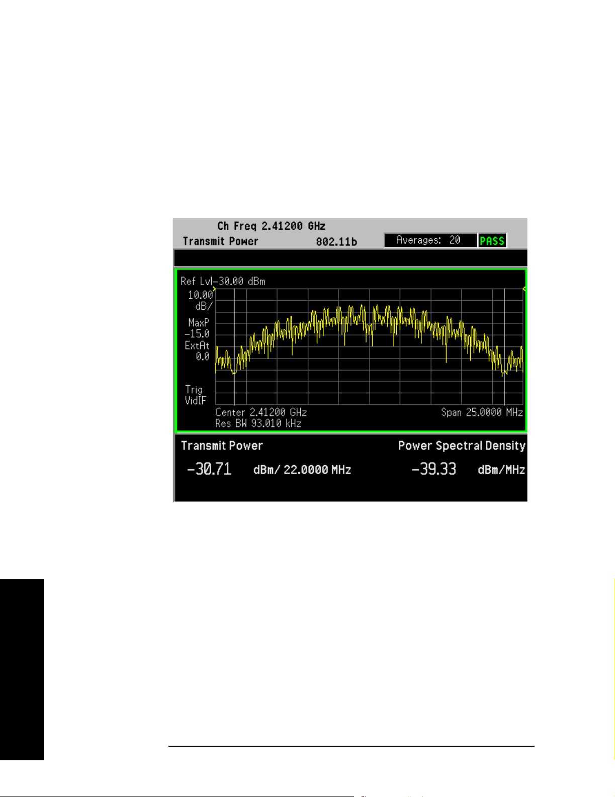
Making Measurements
One Button Measurement Examples
Transmit Power Measurement Procedure
Step 1. Press the
MEASURE, Transmit Power keys to initiate the transmit power
measurement.
The Transmit Power measurement result should look like Figure 2-2
on page 45 and Figure 2-3 on page 46. The Spectrum window and the
Metrics window show the total power in a specified bandwidth and the
Power Spectral Density in the occupied channel.
Figure 2-3 Transmit Power Measurement Result - 802.11b Signal (Default)
Making Measurements
Step 2. Press the
Meas Setup to change the measurement parameters from
their default conditions.
To change the Transmit Power Span, press
and enter a value, then select a unit key.
To change Transmit Power measurement limits, press
Psd Limits and enter a value.
or
For more details about changing measurement parameters, see
Transmit Power “Meas Setup” on page 107.
Step 3. To adjust the display:
Press the
AMPLITUDE/Y Scale key, enter a value for Scale/Div key, then
press the unit key.
To change the absolute power reference, press
46 Chapter 2
Integ BW, Transmit Pwr Span
Limits, Pwr Limits
Ref Value and enter a

value, then select a unit key.
Making Measurements
One Button Measurement Examples
To change the vertical display reference, press
among
Top, Ctr or Bot.
To switch the scale coupling function between
Coupling
NOTE To change a display parameter like AMPLITUDE/Y Scale, Scale/Div, the
key.
Ref Position to switch
On and Off, press Scale
window must be made “active”, which is shown on the display as the
window with a green outline. Press
Next Window to activate the other
window, and Zoom to display only a single window.
If you have a problem, and get an error message, see “Interpreting
Error Codes” on page 65 or the “Instrument Messages and Functional
Tests” manual.
Transmit Spectrum Mask Measurement
This section explains how to make a Transmit Spectrum Mask
measurement on a WLAN signal.
This measurement compares the Power Spectral Density (PSD) within
the given offset channels on both sides of the carrier frequency, to levels
allowed by the standard.
The results are shown in Spectrum window as well as in Metrics
window. The results of each offset segment can be viewed separately.
Transmit Spectrum Mask Measurement Procedure
Step 1. Press the
spectrum emission mask measurement.
The Transmit Spectrum Mask measurement result to display all
segment should look like Figure 2-4 on page 48 and Figure 2-5 on page
48. The Metrics window shows the reference PSD and the absolute peak
PSD which correspond to the frequency bands on both sides of the
reference channel. The absolute PSD is indicated by the yellow lines.
MEASURE, Transmit Spectrum Mask keys to initiate the
Making Measurements
Chapter 2 47

Making Measurements
One Button Measurement Examples
Figure 2-4 Transmit Spectrum Mask Result - 802.11a Offset All (Default)
Figure 2-5 Transmit Spectrum Mask Result - 802.11b Offset All (Default)
Making Measurements
48 Chapter 2

Making Measurements
One Button Measurement Examples
Step 2. Press the Meas Setup to change the measurement parameters from
their default conditions. For example, you can:
To change the reference channel parameters, press
enter values for
Chan Integ BW, Chan Span and Res BW.
To change the spectrum mask limits, press
Limits, then enter values for Abs Start, Abs Stop, Rel Start and Rel Stop,
and select a
Fail Mask.
To specify the offset frequency, press
select an offset from
Res BW.
A to E, and set values for Start Freq, Stop Freq and
For more details about changing measurement parameters, see
Transmit Spectrum Mask “Meas Setup” on page 124.
Step 3. To change the display scale:
Press
unit key, like
Enter a value for
AMPLITUDE/Y Scale, enter a value for Scale/Div key, then press the
dB key.
Ref Value key, then press the unit key, like dBm/Hz
key.
Switch among
Switch between
Top, Ctr or Bot by pressing Ref Position key.
On or Off by pressing Scale Coupling key.
Ref Channel, then
Offset/Limits, More and
Offset/Limits, then cycle Offset to
Step 4. To change the display view, press the
the following settings or toggle the display function of the offset sides
between negative and positive:
Press
Press
Press
Press
Press
Press
Switch between
To change a display parameter like
ALL (Default) key to display all the frequency offset segments.
Offset A key to display the frequency offset A.
Offset B key to display the frequency offset B.
Offset C key to display the frequency offset C.
Offset D key to display the frequency offset D.
Offset E key to display the frequency offset E.
Neg or Pos by pressing Offset key.
AMPLITUDE/Y Scale, Scale/Div the
window must be made “active”, which is shown on the display as the
window with a green outline. Press
window, and
Zoom to display only a single window.
Next Window to activate the other
If you have a problem, and get an error message, see “Interpreting
Error Codes” on page 65 or the “Instrument Messages and Functional
Tests” manual.
TRACE/VIEW key, then select from
Making Measurements
The FAIL indicator is displayed, when any offset result fails, no matter
Chapter 2 49

Making Measurements
One Button Measurement Examples
which offset view you are using.
Only when all results of the valid offsets are successful will
Pass/Fail
indicator bar show “PASS”.
Power vs. Time Measurement
This section explains how to make a Power versus Time measurement
on a WLAN signal.
This measurement indicates whether the timing of the transmission of
the 802.11b/g signal is consistent with the WLAN 802.11b/g standard.
The results are displayed graphically as well as in Metrics window.
NOTE This measurement is available only when 802.11b or 802.11g
ERP-DSSS/CCK/PBCC standard and operating mode is selected.
Power vs. Time Measurement Procedure
Step 1. Press the
Time measurement. The measurement result should look like Figure
2-6 on page 50.
Figure 2-6 Power Vs Time Result - 802.11b RF Envelope View (Default)
MEASURE, Power vs T ime keys to initiate the Power versus
Making Measurements
50 Chapter 2

Making Measurements
One Button Measurement Examples
Step 2. Press the Meas Setup to change the measurement parameters from
their default conditions. For example, you can:
Press
Burst Time and enter an appropriate value. The Burst Time
should be no less than the total length of a burst.
To change the searching window length, press
entering a value. You need to set the Ramp Time Length longer than
the actual ramp time, otherwise the ramp may be lost.
To change the measurement limits, press
Ramp Up Time
Pow er-on ramp mask means when ramp up exceeds the limit, the
, Max Ramp Down Time and select a Fail mask.
measurement overall result fails regardless of ramp down results.
mask means when both ramp up and ramp down exceed the limits, the
measurement overall result fails.
For more details about changing measurement parameters, see Power
vs. Time “Meas Setup” on page 139.
Step 3. To change the display scale, press the
can change any of the following settings:
Enter a value for
Enter a value for
Switch among
Scale/Div key, then press the unit key.
Ref Value key, then press the unit key.
Top, Ctr or Bot by pressing Ref Position key.
Ramp Time Length and
Limits, then set values for Max
Both
AMPLITUDE/Y Scale key, then you
Switch between
On or Off by pressing Scale Coupling key.
Step 4. To change the display view, press the
the following settings:
Press
Press
To change a display parameter like
Burst key to display Power vs. Time view.
Rise & Fall key to display Power-on and Power-down Ramp view.
AMPLITUDE/Y Scale, Scale/Div the
window must be made “active”, which is shown on the display as the
window with a green outline. Press
window, and
Zoom to display only a single window.
Next Window to activate the other
If you have a problem, and get an error message, see “Interpreting
Error Codes” on page 65 or the “Instrument Messages and Functional
Tests” manual.
TRACE/VIEW key, then select from
Making Measurements
Chapter 2 51

Making Measurements
One Button Measurement Examples
Spectral Flatness Measurement
NOTE Spectral Flatness measurement is available only when 802.1 1a, 802.1 1g
ERP-OFDM, or 802.11g DSSS-OFDM standard and operating mode is
selected.
This section explains how to make a Spectral Flatness measurement on
a WLAN signal.
The Spectral Flatness measurement can test energy flatness of
sub-carriers on an OFDM signal.
NOTE In conformance with the WLAN standard, the zero sub-carrier is not
included in this measurement computation. See “The relationship
between Center Frequency (CtrFreq) and Channel No. (nch):” on
page 77.
Spectral Flatness Measurement Procedure
Step 1. Press the
MEASURE, Spectral Flatness keys to initiate the spectral
flatness measurement. The Spectral Flatness measurement result
should look like Figure 2-7 on page 52.
Figure 2-7 Spectral Flatness Measurement Result - 802.11a Signal (Default)
Making Measurements
Step 2. Press the
52 Chapter 2
Meas Setup to change the measurement parameters from

One Button Measurement Examples
their default conditions. For example, you can:
Making Measurements
Press
Search Length and entering a value no less than the total length of
a burst.
To change the measurement limits, press
B, and set Upper Limit and Lower Limit for the selected offset segment.
Offset A for 802.11a includes the carriers −16 to 16.
Offset B for 802.11a includes the carriers −26 to −17 and 17 to 26.
For more details about changing measurement parameters, see
Spectral Flatness “Meas Setup” on page 152.
Step 3. To change the display scale, press the
Scale
keys, then you can change any of the following settings:
Enter a value for
Enter a value for
Scale/Div key, then press the unit key.
Ref Value key, then press the unit key.
Switch reference position by pressing
Switch between
To change a display parameter like
On or Off by pressing Scale Coupling key.
AMPLITUDE/Y Scale, Scale/Div the
window must be made “active”, which is shown on the display as the
window with a green outline. Press
window, and
Zoom to display only a single window.
Next Window to activate the other
Limits, then select Offset A or
SPAN/X Scale or AMPLITUDE/Y
Ref Position key.
If you have a problem, and get an error message, see “Interpreting
Error Codes” on page 65 or the “Instrument Messages and Functional
Tests” manual.
Modulation Accuracy Measurements
This section explains how to make a Modulation Accuracy
measurement on a WLAN 802.11 signal.
Modulation Accuracy is a measure of phase and amplitude modulation
quality that relates the performance of the actual signal compared to an
ideal signal as a percentage, calculated over the course of the ideal
constellation.
The results are displayed graphically as well as in Metrics windows.
Making Measurements
Chapter 2 53

Making Measurements
One Button Measurement Examples
Modulation Accuracy Measurement Procedure
Step 1. Press the
MEASURE, Modulation Accuracy keys to initiate the
modulation accuracy measurement.
The Modulation Accuracy measurement result should look like Figure
2-8 on page 54 for 802.11 a signal and Figure 2-9 on page 55 for 802.11b
signal. The measurement values for RMS EVM, Pk EVM, Freq Error, Sym
Clock Err and IQ Offset are shown in the summary result window.
Figure 2-8 Modulation Accuracy Result - 802.11a Polar View (Default)
Making Measurements
54 Chapter 2

Making Measurements
One Button Measurement Examples
Figure 2-9 Modulation Accuracy Result - 802.11b Polar View (Default)
Step 2. Press the
Meas Setup to change the measurement parameters from
their default conditions.
For more details about changing measurement parameters, see
Modulation Accuracy “Meas Setup” on page 172.
Step 3. Press the
View/Trace, I/Q Error keys to select the alternate display
combination of a magnitude error window, a phase error window, a
EVM graph window, and a modulation summary result window. See
Figure 2-10 on page 56.
NOTE I/Q Error key is available only when 802.11b or 802.11g
ERP-DSSS/CCK/PBCC standard and operating mode is selected.
Making Measurements
Chapter 2 55

Making Measurements
One Button Measurement Examples
Figure 2-10 Modulation Accuracy Result - 802.11b Signal I/Q Error View
To change a display parameter like
AMPLITUDE/Y Scale, Scale/Div the
window must be made “active”, which is shown on the display as the
window with a green outline. Press
window, and
Zoom to display only a single window.
Next Window to activate the other
Making Measurements
56 Chapter 2

Making Measurements
One Button Measurement Examples
Step 4. Press the View/Trace, OFDM EVM key to select the alternate display
combination of a EVM vs. Carrier window, a EVM vs. Symbol window, a
I/Q Measured Polar Constellation window and a Numeric Results
window. See Figure 2-11 on page 57.
NOTE OFDM EVM key is available only when 802.11a, 802.11g EPR-OFDM or
802.11g DSSS-OFDM standard and operating mode is selected.
Figure 2-11 Modulation Accuracy Result - 802.11a Signal OFDM EVM View
Step 5. Press the
window. See Figure 2-12 on page 58 for 802.11a and Figure 2-13 on
page 58 for 802.11b.
Chapter 2 57
View/Trace, Demod Bits key to display a demodulated data bits
Making Measurements

Making Measurements
One Button Measurement Examples
Figure 2-12 Modulation Accuracy Result - 802.11a Signal Demod Bits View
Figure 2-13 Modulation Accuracy Result - 802.11b Signal Demod Bits View
Making Measurements
58 Chapter 2

Making Measurements
One Button Measurement Examples
Step 6. Press the View/Trace, Numeric Results key to display the modulation
accuracy summary data, peak and rms EVM, frequency error, symbol
clock error, IQ offset, quadrature error and IQ gain imbalance in a text
window. See Figure 2-14 on page 59 and Figure 2-15 on page 60.
Figure 2-14 Modulation Accuracy Result - 802.11a Numeric Results View
Step 7. Press the
settings.
Switch from constellation, vector or vector&constellation graph by
pressing the
The default polar graph setting is constellation graph for 802.11a
signals, and the vector&constellation graph for 802.11b.
Enter a value for the
specify the total number of I/Q points displayed during each
measurement interval.
Enter a value as an offset from the first I/Q points for the
key.
Offset
Switch between
Switch between
Chapter 2 59
Display to change display parameters from the default
I/Q Polar Vector/Constln key.
I/Q Points key and press the unit key symbols, to
I/Q Points
On or Off by pressing I/Q Rotation 45.0 deg key.
On or Off by pressing Full Vector (Background) key.
Making Measurements
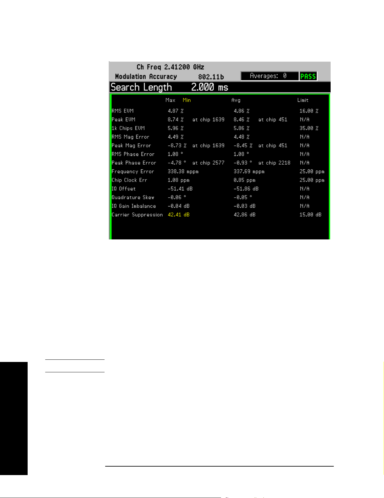
Making Measurements
One Button Measurement Examples
Figure 2-15 Modulation Accuracy Result - 802.11b Numeric Results View
Making Measurements
If you have a problem, and get an error message, see “Interpreting
Error Codes” on page 65 or the “Instrument Messages and Functional
Tests” manual.
Power Stat CCDF Measurements
This section explains how to make a power statistics CCDF
measurement on a WLAN device.
Power Complementary Cumulative Distribution Function (CCDF)
curves characterize the higher level power statistics of a digitally
modulated signal.
The results are displayed graphically as well as in Metrics window.
NOTE The CCDF measurement does not have Pass/Fail indicators.
Power Stat CCDF Measurement Procedure
Step 1. Press the
statistics CCDF measurement.
The CCDF measurement result should look like Figure 2-16 on page 61
and Figure 2-17 on page 61. The measurement results for Average
Power, Peak Power and the power statistic data are shown in Metrics
window of the left screen. The tested CCDF curve is indicated by the
MEASURE, Power Stat CCDF keys to initiate the power
60 Chapter 2
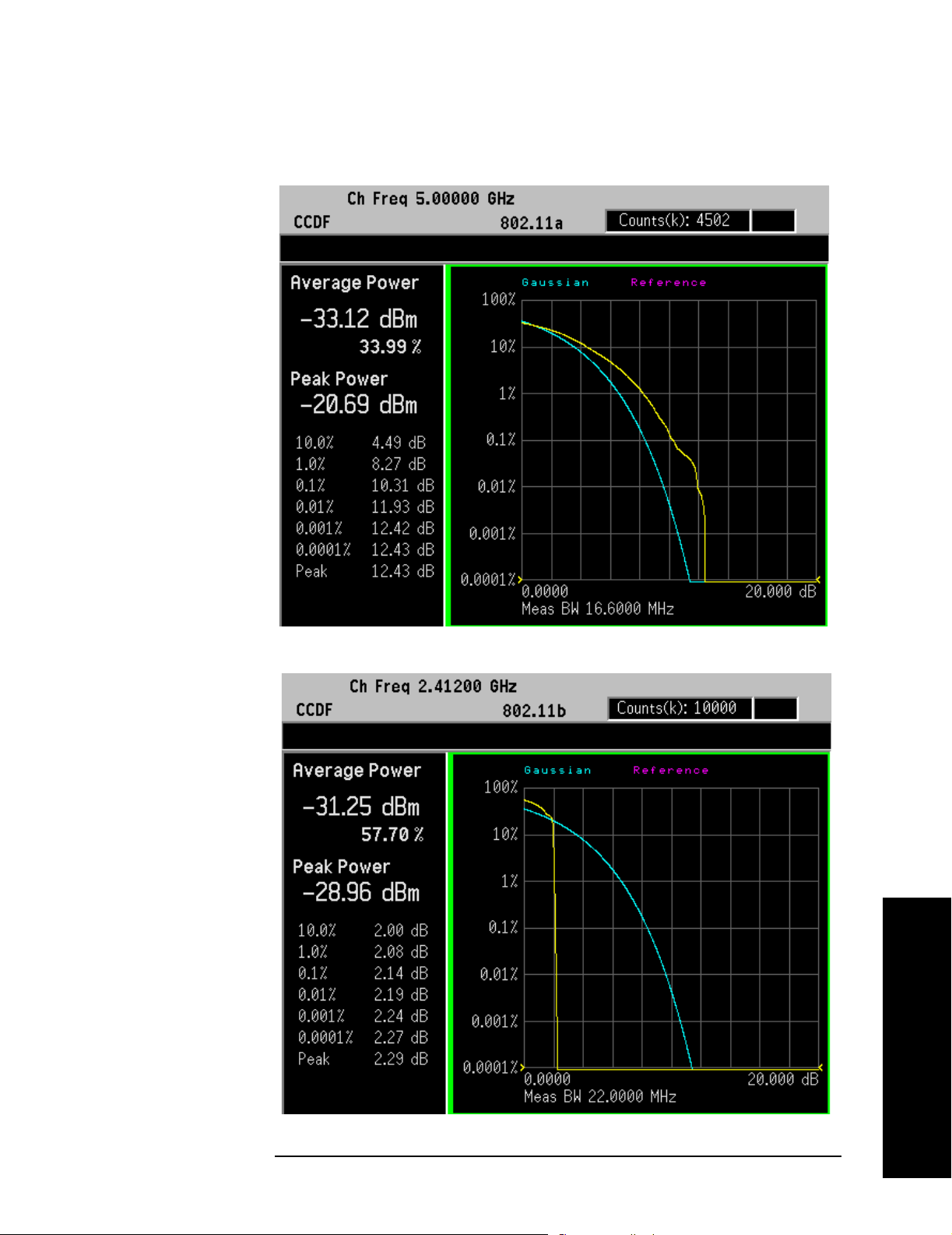
Making Measurements
One Button Measurement Examples
yellow lines.
Figure 2-16 Power Statistics CCDF Result - 802.11a Signal (Default)
Figure 2-17 Power Statistics CCDF Result - 802.11b Signal (Default)
Making Measurements
Chapter 2 61

Making Measurements
One Button Measurement Examples
Step 2. Press the Meas Setup to change the measurement parameters from
their default conditions.
In an OFDM signal, the burst includes training symbols, the signal
field and the data field. To accurately perform a useful CCDF
measurement of a device such as a power amplifier (PA), only the signal
and data portions of the burst should be included and the measurement
must be made on the data portion. This can be done by adjusting the
trigger parameters within the CCDF measurement:
First, identify the total length of the burst. This can be done using the
Waveform Measurement. You can use
Waveform (Time Domain)
measurement to show the whole burst, place a marker on the left edge
of the burst, then use the knob to place a delta marker at the falling
edge of the same burst. The length of the burst will display on the top
left of Waveform window.You need to elect the correct trigger source to
get a stable signal display and then use marker to determine the burst
length. For example, you read the burst length as 104 us.
Second, select the
Source
in Meas Setup menu, like Ext Front.
Third, select the appropriate
Power Stat CCDF measurement and set the correct Trig
Meas Interval in Meas Setup menu, like 88
us. Then set trigger offset 16 us for CCDF measurement by pressing
Trig and Ext Front.
The training portion of the OFDM burst occupies the first 16 us, so the
CCDF measurement should only analyze the portion of the burst
between 16 us and 104 us.
Now you can get CCDF result. If not, press
For more details about changing measurement parameters, see Power
Stat CCDF “Meas Setup” on page 202.
Step 3. To change the display scale, press the
for
Scale/Div key, then press the dB key.
SPAN/X Scale key, enter a value
Step 4. To change the display parameters, press the
Press
Switch between
Switch between
Store Ref Trace to define user’s reference trace.
On or Off by pressing Ref Trace key.
On or Off by pressing Gaussian Line key.
Restart.
Display key:
Making Measurements
To change a display parameter like
AMPLITUDE/Y Scale, Scale/Div the
window must be made “active”, which is shown on the display as the
window with a green outline. Press
window, and
Zoom to display only a single window.
Next Window to activate the other
If you have a problem, and get an error message, see “Interpreting
Error Codes” on page 65 or the “Instrument Messages and Functional
Tests” manual.
62 Chapter 2

Making Measurements
One Button Measurement Examples
Spectrum and Waveform Measurements
The Spectrum and Waveform measurements available in PSA Option
217 are the same as those available in basic mode. See the PSA Basic
Mode User’s Guide Option B7J for more detail on the Spectrum and
Waveform measurements, remote commands, front-panel keys,
conceptual information and menu maps.
Chapter 2 63
Making Measurements

Making Measurements
Using Basic Mode
Using Basic Mode
Basic mode is a standard feature of E4406A Transmitter T esters , and is
part of Option B7J for the PSA Series Spectrum Analyzers. Basic mode
is not related to a particular communications standard. That is, it does
not default to measurement settings that are for any specific standard.
You may want to use Basic Mode if you are making measurements on a
signal that is not based on a specific digital communications standard.
Basic Mode in E4406A VSA Series Transmitter Testers
There are five generic measurements available under the MEASURE key
in Basic mode:
• Adjacent Channel Power (ACP)
• Channel Power
• Power Statistics CCDF
• Spectrum measurement (frequency domain).
• Waveform measurement (time domain)
The ACP, Channel Power, and Power Stat CCDF measurements are
fully described in the VSA Series User’s Guide. Please refer to that
manual for complete information on these measurements.
Spectrum and Waveform Measurements
These measurements provide a spectrum measurement mode that is
similar to a standard spectrum analyzer , and a waveform measurement
mode that is similar to a microwave oscilloscope. Unlike those standard
analyzers, these measurements are optimized for digitally modulated
signals, so they can be used to output the measured I/Q data.
For your convenience, Spectrum and Waveform measurements are also
available in this mode, with the same functionality, so you can refer to
the sections included in this chapter for information about using them.
Basic Mode in PSA Series Spectrum Analyzers
There are two generic measurements available under the MEASURE key
in Basic mode:
Making Measurements
• Spectrum measurement (frequency domain).
• Waveform measurement (time domain)
These Spectrum and W aveform measurements are also available in this
mode, with the same functionality, so you can refer to the sections
included in this chapter for information about using them.
64 Chapter 2

Making Measurements
Interpreting Error Codes
Interpreting Error Codes
During the execution of your measurement you may encounter
problems which generate error codes. Reference to the following
common errors may be helpful.
If Err is shown in the annunciator bar , press the
System, Show Err or s to
read the detailed error information.
• Awaiting Trig, no AUTO Trig
Press
source. And check the trig type is correct by pressing
Press
Meas Setup, Trig Source, and then select the proper trigger
Trig hardkey.
Restart to make another measurement and observe the results.
Re-adjust the ADC as necessary to obtain a valid measurement.
• Error Code 16 “Input overload”
This error means that your measurement has erroneous results due
to the excessive input power level. To correct this condition, the
input signal level must be reduced by using the internal and/or
external attenuator.
Press the
Mode Setup, Input, Input Atten keys to enter an attenuation
value to reduce the transmitted power from the MS. This allowable
range is up to 40 dB.
To attenuate more than 40 dB, connect your external attenuator
between the RF INPUT port and the DUT. Be sure to add its
attenuation value to the readings of the measurement result.
To automate this calculation, press the
Mode Setup, Input, Ext Atten
keys to enter the additional attenuation value. The allowable range
is up to 100 dB. The power readings of the measurement will take
into account the external attenuation value.
• Error Code 601 “Signal too noisy”
This error means that your input signal is too noisy to capture the
correct I/Q components. To make a more stable measurement the
trigger source may need to be set to
Frame, for example.
• Error Code 604 “Can not correlate to input signal”
This error means that the tester has failed to find any active
channels in the input signal as specified. To improve the correlation
some critical parameter needs to be adjusted, like the input signal
level or scramble code, for example.
For more details consult the chapter in this book dedicated to the
measurement in question, or see the “Instrument Messages and
Functional Tests” manual.
Chapter 2 65
Making Measurements

Making Measurements
Interpreting Error Codes
Making Measurements
66 Chapter 2

Front-Panel Key and SCPI Command
Reference
Chapter 3
3 Front-Panel Key and SCPI
Command Reference
This chapter provides detailed descriptions of the front-panel keys and the
associated SCPI commands and screens used to set up and make WLAN
measurements.
67

Front-Panel Key and SCPI Command Reference
Instrument Front Panel Highlights
Reference
Front-Panel Key and SCPI Command
3.1 Instrument Front Panel Highlights
The most commonly used function keys on the PSA front panel are located as shown in the
illustrations below. The operation of the keys is briefly explained on the following page. Refer to
your User’s Guide for complete details on all keys.
Figure 3-1 PSA Selected Front Panel Key Locations
68
Chapter 3

Front-Panel Key and SCPI Command Reference
Instrument Front Panel Highlights
1. The On/Off switch toggles the AC Line power on or off. A green LED will light when the
instrument is On. When energized in the standby mode, a yellow LED is lit above the
On/Off
switch.
2. FREQUENCY Channel accesses a display key menu that to set the analyzer center frequency in
units of Hz, kHz, MHz, or GHz, or by channel number. These parameters apply to all
measurements in the current mode.
3. MODE accesses a key menu to select one of the measurement personalities installed in the
instrument. Each mode is independent from all other modes.
4. Mode Setup accesses a key menu that sets parameters specific to the current mode and affect
all measurements within that mode.
5. MEASURE accesses a display key menu to initiate one of the various measurements that are
specific to the current mode.
6. Meas Setup accesses the menus of test parameters that are specific to the current
measurement.
Front-Panel Key and SCPI Command
Reference
7. Restart causes a measurement to start again from the initial process according to the current
measurement setup parameters.
8. The RF INPUT port “N” connector allows you to apply an external RF signal. The maximum
input power level is shown next to the port.
9. The Data Entry keypad is used to enter numeric values to parameters. A value from this keypad
will be displayed in the active function area of the screen, the n the value will become valid for
the current measurement upon pressing the
Enter key or selecting a unit of measurement
depending on the parameter.
10.The Display Menu keys allow you either to activate a feature or to access a more detailed
sub-menu. An arrow on the right side of a softkey label indicates that the key has a further
selection menu. The active menu key is highlighted, however, grayed-out keys are currently
unavailable for use or are only to show information. If a menu has multiple pages, successive
pages are accessed by pressing the
11. Pressing the Return key allows you to exit from the current menu and display the previous
menu. Often, pressing a menu key will invoke a multi-page sub-menu. Pressing the
More key located at the bottom of the menu.
Return key
will show the menu “above” it, not a previous page. When you activate another measurement,
the return list is cleared. The
Return key will not return you to a previously activated mode,
nor will it alter any values you have entered in previous menus.
Chapter 3
69

Front-Panel Key and SCPI Command Reference
Programming Command Compatibility Across Model Numbers and Across Modes
Reference
Front-Panel Key and SCPI Command
3.2 Programming Command Compatibility
Across Model Numbers and Across Modes
3.2.1 Across PSA Modes: Command Subsystem Similarities
When you select different modes you get different sets of available programming commands. That
is, only the commands that are appropriate for the current mode are available. Also, some
commands have the same syntax in different modes but have different ranges or settings that are
only appropriate to the current mode.
The following table shows which command subsystems are the same across different modes. If
there is no “X” by a particular subsystem, then the set of available commands is different in those
modes. Command ranges or defaults may also be different. Refer to the programming command
descriptions in the documentation for each mode for details.
Command Subsystem Same command set is
available:
SA mode compared with the
application modes: Digital
Modulation, Basic, WLAN,
W-CDMA, cdmaOne,
cdma2000, 1xEV-DO, GSM,
EDGE, NADC, or PDC
Same command set is
available:
SA mode compared with the
application modes: Phase
Noise, Noise Figure,
TD-SCDMA
IEEE common commands X X
ABORt X X
CALCulate
CALibration X X
CONFigure
COUPle not available in these application
modes
DISPlay
FETCh
FORMat X
HCOPy X X
INITiate
INPut not available in these application
modes
MEASure
MEMory X X
not available in these
application modes
X
70
Chapter 3

Front-Panel Key and SCPI Command Reference
Programming Command Compatibility Across Model Numbers and Across Modes
Front-Panel Key and SCPI Command
Reference
Command Subsystem Same command set is
available:
SA mode compared with the
application modes: Digital
Modulation, Basic, WLAN,
W-CDMA, cdmaOne,
cdma2000, 1xEV-DO, GSM,
EDGE, NADC, or PDC
MMEMory X X
MMEMory:STORe:TRACe not available in these application
modes
READ
[SENSe]
[SENSe:]CHANnel
[SENSe:]CORRection
[SENSe:]FEED
[SENSe:]FREQuency:CE
X
NTer
Same command set is
available:
SA mode compared with the
application modes: Phase
Noise, Noise Figure,
TD-SCDMA
X
[SENSe:]FREQuency:
<other subsystems>
not available in these application
modes
[SENSe:]<measurement>
[SENSe:]POWer
[SENSe:]RADio
[SENSe:]SYNC
STATus X X
SYSTem X X
TRACe not available in these application
modes
TRIGger
UNIT X X
not available in these
application modes
X
Chapter 3
71

Front-Panel Key and SCPI Command Reference
Programming Command Compatibility Across Model Numbers and Across Modes
3.2.2 Across PSA Modes: Specific Command Differences
Reference
Front-Panel Key and SCPI Command
Some programming commands operate differently depending on which Mode the analyzer is set
to.
Command
CONFigure:
<measurement>
*ESE default Default is 255 which means that
TRIGger
commands
Spectrum Analysis, Phase Noise
and Noise Figure Mode
Accesses the measurement and sets
the instrument settings to the
defaults. Averaging is turned on and
set to 10. The instrument is put in
single measurement mode. It does
not initiate a measurement. Use
INIT:IMM to make one
measurement.
every error/status bit change that has
occurred will be returned with a
*ESR? query. You must set the value
of *ESE to choose only the bits/status
that you want returned.
For these modes, only one trigger
source can be selected and it will be
common across the modes. Also, only
one value can be set for the trigger
delay, level, or polarity.
Basic, cdmaOne, cdma2000,
1xEV-DO, W-CDMA, GSM, EDGE,
NADC, PDC Modes
Accesses the measurement and sets
the instrument settings to the
defaults. If you were already in
single measurement mode, it takes
one measurement and then waits. If
you were in continuous measurement
mode it continues to measure.
Default is 0 which means that none
of the error/status bit changes that
have occurred will be returned with a
*ESR? query. Yo u must set the value
of *ESE to choose the bits/status that
you want returned.
For these modes, a unique trigger
source can be selected for each mode.
Also, each trigger source can have
unique settings for the its delay,
level, and polarity.
Saving and
recalling traces
Traces can only be saved when in the Spectrum Analysis mode
(MMEM:STOR:TRAC). This is because the instrument state must be saved
along with the trace data and the state data varies depending on the number
of modes currently available in the instrument.
72
Chapter 3

Front-Panel Key and SCPI Command Reference
Programming Command Compatibility Across Model Numbers and Across Modes
3.2.3 Using Applications in PSA Series vs. VSA E4406A
NOTE This information only applies to the application modes:
Basic, cdmaOne, cdma2000, 1xEV-DO, W-CDMA, GSM, EDGE,
NADC, and PDC.
Command PSA Series VSA E4406A: A.04.00 VSA E4406A: A.05.00
Front-Panel Key and SCPI Command
Reference
*RST Resets instrument,
putting it in
continuous
measurement mode.
Use INIT:CONT OFF
to select single
measurement mode
and INIT:IMM to start
one measurement.
CONFigure:
<measurement>
*ESE default Default is 255 which
Accesses the
measurement and sets
the instrument
settings to the defaults.
If you were already in
single measurement
mode, it takes one
measurement and then
waits.
means that every
error/status bit change
that has occurred will
be returned with a
*ESR? query. You must
set the value of *ESE
to choose only the
bits/status that you
want returned.
Resets instrument,
putting it in single
measurement mode.
One measurement is
initiated when the
command is sent.
Same as PSA.
Accesses the
measurement and sets
the instrument settings
to the defaults. If you
were already in single
measurement mode, it
takes one measurement
and then waits.
Default is 0 which
means that none of the
error/status bit changes
that have occurred will
be returned with a
*ESR? query. You must
set the value of *ESE to
choose the bits/status
that you want returned.
Resets instrument,
putting it in single
measurement mode. No
measurement is
initiated when the
command is sent. Use
INIT:IMM to start one
measurement.
Accesses the
measurement and sets
the instrument settings
to the defaults. If you
were already in single
measurement mode, it
does not initiate a
measurement. Use
INIT:IMM to make one
measurement.
Same as VSA A.04.00.
Default is 0 which
means that none of the
error/status bit changes
that have occurred will
be returned with a
*ESR? query. You must
set the value of *ESE to
choose the bits/status
that you want returned.
Chapter 3
*LRN The command is not
available.
The command is
available.
The command is
available.
73

Front-Panel Key and SCPI Command Reference
Programming Command Compatibility Across Model Numbers and Across Modes
Command PSA Series VSA E4406A: A.04.00 VSA E4406A: A.05.00
Reference
Front-Panel Key and SCPI Command
TRIGger
commands
AUTO ON|OFF
control and
setting manual
values
In Spectrum Analysis
mode only one value
can be set for the
trigger’s source, delay,
level, or polarity.
Basic, GSM, EDGE,
cdmaOne, cdma2000,
W-CDMA, NADC, PDC
modes function the
same as VSA
We recommend that
you set a function’s
automatic state to
OFF, before you send it
your manual value.
Some functions will
turn off the automatic
mode when you send a
specific manual value,
but others will not.
This also varies with
the instrument model.
You can select a unique
trigger source for each
mode. Each trigger
source can have unique
settings for the its delay,
level, and polarity.
We recommend that you
set a function’s
automatic state to OFF,
before you send it your
manual value.
Some functions will turn
off the automatic mode
when you send a specific
manual value, but
others will not. This also
varies with the
instrument model.
Same as VSA A.04.00.
You can select a unique
trigger source for each
mode. Each trigger
source can have unique
settings for the its
delay, level, and
polarity.
We recommend that you
set a function’s
automatic state to OFF,
before you send it your
manual value.
Some functions will
turn off the automatic
mode when you send a
specific manual value,
but others will not. This
also varies with the
instrument model.
74
Chapter 3

Front-Panel Key and SCPI Command Reference
Front-Panel Keys
3.3 Front-Panel Keys
NOTE Only front panel keys affected by selection of WLAN mode are described here. For a
complete description of all front panel keys see the PSA Series User’s Guide.
3.3.1 FREQUENCY Channel
Displays the menu of frequency functions.
3.3.1.1 Center Frequency
Sets the center frequency to be measured for the selected band. It is coupled with Channel No..
Front-Panel Key and SCPI Command
Reference
Mode: WLAN
Key Path:
Remote Command: [:SENSe]:FREQuency:CENTer <freq>
Unit: Hz | kHz | MHz | GHz
Default: 2.412 GHz (See Table 3-1, “Center Frequency Factory Preset”)
State Saved: Saved in instrument state.
Range: See Table 3-2, “Center Frequency Range”
Dependencies/Couplin
gs:
Remote Command
Notes:
Example: FREQ:CENT 2.412 GHz
FREQUENCY/Channel
[:SENSe]:FREQuency:CENTer?
Couple with Channel No., see Note below.
You must be in the WLAN mode to use this command. Changing
Center Frequency will effect all measurements in the selected
WLAN standard.
FREQ:CENT?
NOTE If the Center Frequency value entered does not exactly correlate with a Channel
No., the key label changes to display the closest Channel No. to the selected
frequency.
Chapter 3
75

Reference
Front-Panel Key and SCPI Command
Front-Panel Key and SCPI Command Reference
Front-Panel Keys
T able 3-1 Center Frequency Factory Preset
Radio Center Frequency
(Preset/Default):
802.11a 5 GHz
802.11b 2.412 GHz
802.11g ERP-OFDM 2.412 GHz
802.11g
ERP-DSSS/CCK/PBCC
802.11g DSSS-OFDM 2.412 GHz
2.412 GHz
Table 3-2 Center Frequency Range
Model Center Frequency
Range:
E4440A 1 kHz ~ 26.5 GHz
E4443A 1 kHz ~ 6.7 GHz
E4445A 1 kHz ~ 13.2 GHz
NOTE Although the analyzer allows entry of frequencies greater than its specified range,
analyzer performance will be degraded if it is used beyond the specified frequency
range.
3.3.1.2 Channel No.
Sets the analyzer to a frequency that corresponds to the Channel No.. You can enter the number
of channel to be measured for the selected band. It is coupled with Center Frequency.
NOTE Channel No. Range is limited to valid channels for the selected band.
Mode: WLAN
Key Path:
Remote Command: [:SENSe]:CHANnel <integer>
Default: 1 (See Table 3-3, “Channel No. Factory Preset”)
76
FREQUENCY/Channel
[:SENSe]:CHANnel?
Chapter 3

Front-Panel Key and SCPI Command Reference
State Saved: Saved in instrument state.
Range: See Table 3-3, “Channel No. Factory Preset”
Front-Panel Key and SCPI Command
Front-Panel Keys
Reference
Dependencies/Couplin
gs:
Remote Command
Notes:
Couple with Center Freq (See Note below)
You must be in the WLAN mode to use this command. Changing
Channel No. will effect all measurements in the selected WLAN
standard.
Table 3-3 Channel No. Factory Preset
Radio Channel No.
(Preset/Default):
802.11a 0 0 ~ 200
802.11b 1 1 ~ 14
802.11g ERP-OFDM 1 1 ~ 14
802.11g
ERP-DSSS/CCK/PBCC
802.11g DSSS-OFDM 1 1 ~ 14
11 ~ 14
Channel No. Range
NOTE The relationship between Center Frequency (CtrFreq) and Channel No. (nch):
• For 802.11b/g:
CtrFreq (MHz) = 2407 + 5 * nch, where nch = 1,2,...,13
CtrFreq (MHz) = 2484, where nch = 14
• For 802.11a:
CtrFreq (MHz) = 5000 + 5 * nch, where nch = 0,1,2,...,200
3.3.2 Meas Control
These functions allow you to pause and resume the currently sele cted measure ment and to select
between continuous or single measurements.
3.3.2.1 Restart
Press this key to repeat the current measurement from the beginning, while retaining the current
measurement settings. This is equivalent to the
Key Path:
Meas Control
Restart front panel key.
Chapter 3
77

Front-Panel Key and SCPI Command Reference
Front-Panel Keys
Remote Command: :INITiate:RESTart
Reference
Front-Panel Key and SCPI Command
Remote Command
Notes:
Example: :INIT:REST
This command is equivalent to sending an :ABORt command
followed by an:INITiate[:IMMediate] command.
3.3.2.2 Measure
Press this key to toggle the measurement state between
This key has a different function than the
MEASURE front panel key. When set to Single, the
Single and Cont (continuous). NOTE:
measurement will continue until it has reached the specified number of averages set by the
average counter . When set to
Cont, the measurement will run continuously and execute averaging
according to the current average mode, either repeat or exponential.
Key Path
Factory Preset Cont
State Saved Saved in instrument state.
Remote Command :INITiate:CONTinuous OFF|ON
Remote Command
Notes
Meas Control
When ON, at the completion of each trigger cycle, the trigger
system immediately initiates another trigger cycle.
When OFF, the trigger system remains in an “idle” state until
CONTinuous is set to ON or an :INITiate[:IMMediate]
command is received. On receiving the :INITiate[:IMMediate]
command, it will go through a single trigger cycle, and then
return to the “idle” state.
The query INIT:CONT? returns 1 or 0. 1 is returned when the
instrument is continuous triggering. 0 is returned when it is
single triggering.
Example :I NIT:CONT OFF
3.3.2.3 Pause/Resume
Press this key to pause the current measurement until you reactivate the measurement. Once
toggled, the label of the
Pause key changes to read Resume. The Resume key, once pressed,
continues the active measurement from the point at which it was paused.
Key Path:
Remote Command: :INITiate:PAUSe
Example: :INIT:PAUS
Meas Control
:INITiate:RESume
78
Chapter 3

Front-Panel Key and SCPI Command Reference
Front-Panel Keys
3.3.3 Mode
Accesses any installed personality modes. The minimum set of available modes will be:
• Spectrum Analysis
• Basic
• WLAN
This menu will have additional entries if other personalities have been installed, for example
GSM/EDGE Option 202 or cdmaOne Option BAC.
For information related to the operation of the Spectrum Analysis mode refer to the PSA
User’s/Programmer’s Guide.
For information related to the operation of the Basic mode refer to the PSA Basic Mode Guide.
The WLAN mode provides you the ability to set up your own measurement environment to
analyze signals comply with IEEE 802.11a/b/g standards.
Front-Panel Key and SCPI Command
Reference
3.3.3.1 Instrument Selection by Name (Remote command only)
This remote command allows you to use SCPI to change from the current mode to WLAN mode.
This has the same effect as pressing the
Key Path: Mode
Remote Command: :INSTrument[:SELect] SA|BASIC|WLAN
:INSTrument[:SELect]?
Example: INST WLAN
INST?
WLAN key.
3.3.3.2 Instrument Selection by Number (Remote command only)
This remote command allows you to use SCPI to change from the current mode to WLAN mode
(Option 217). This has the same effect as pressing the
Key Path:
Remote Command: :INSTrument:NSELect 18
Mode
WLAN key.
:INSTrument:NSELect?
Example: INST:NSEL 18
INST:NSEL?
Chapter 3
79

Front-Panel Key and SCPI Command Reference
Front-Panel Keys
3.3.4 Mode Setup
Reference
Front-Panel Key and SCPI Command
Accesses all menus that enable you to change parameters for the available measurements.
3.3.4.1 Radio
Accesses the radio standards menus.
Mode: WLAN
Key Path:
Mode Setup
3.3.4.1.1 WLAN Std
Selects the standard variant that applies to the radio to be tested. The WLAN standards
available are:
• 802.11a
• 802.11b
• 802.11g
Mode: WLAN
Key Path
Remote Command [:SENSe]:RADio:STANdard:WLAN A11|B11|G11
Default G11
State Saved Saved in instrument state.
Remote Command
Notes
Example: RAD:STAN: WLAN A11
Mode Setup, Radio
[:SENSe]:RADio:STANdard:WLAN?
You must be in the WLAN mode to use this command.
Changing Radio will effect all measurements in the WLAN
mode.
RAD:STAN: WLAN?
3.3.4.1.2 Oper Mode
NOTE Oper Mode is available only when WLAN Std is 802.11g.
Sets the operation mode for 802.11g standard. The supported operation modes include:
• ERP-OFDM
• ERP-DSSS/CCK/PBCC
80
Chapter 3

• DSSS-OFDM
Mode: WLAN
Front-Panel Key and SCPI Command
Front-Panel Key and SCPI Command Reference
Front-Panel Keys
Reference
Key Path
Remote Command [:SENSe]:RADio:STANdard:OPMode EDCP|EOFDM|DOFDM
Default EOFDM
State Saved Saved in instrument state.
Remote Command
Notes
Example: RAD:STAN: OPM EDCP
Mode Setup, RadioMode Setup key: Demod;Demod key:Mode
Setup
[:SENSe]:RADio:STANdard:OPMode?
You must be in the WLAN mode to use this command.
Changing Oper Mode will effect all measurements in the WLAN
mode.
RAD:STAN: OPM?
3.3.4.2 Input
Displays the keys that control some of the signal inputs. You can also access this menu by
pressing
Input/Output front-panel key. Please refer to PSA Series Basic Mode Guide for the keys
usage and the remote command details.
Mode: WLAN
Key Path:
Mode Setup
3.3.4.3 Trigger
Displays the keys that control the signal trigger. You can also access this menu by pressing
Trig
front-panel key. Please refer to PSA Series Basic Mode Guide for the keys usage and the remote
command details.
Mode: WLAN
Key Path:
Mode Setup
3.3.4.4 Demod
Displays the menu keys that set the demodulation parameters.
Mode: WLAN
Key Path:
Mode Setup
Chapter 3
81

Reference
Front-Panel Key and SCPI Command
Front-Panel Key and SCPI Command Reference
Front-Panel Keys
3.3.4.4.1 Modulation Format Accesses the demodulation format menu keys allowing you to
specify the demodulation format to use. Modulation Format is automatically set when a radio
standard is selected. You can also specify a modulation format for your testing.
NOTE Following Modulation Format menu is available only when 802.11a, 802.11g
ERP-OFDM, or 802.11g DSSS-OFDM mode is selected.
Selects the Demod format in 802.11a or 802.11g OFDM mode.
Mode WLAN
Key Path
Default AUTO
State Saved Saved in instrument state.
Remote Command [:SENSe]:SYNC:DEMod AUTO|BPSK|QPSK|QAM16|QAM64
Remote Command
Notes
Example SYNC:DEM AUTO
Mode Setup, Demod
[:SENSe]:SYNC:DEMod?
You must be in the WLAN mode to use this command. Changing
Modulation Format will effect all measurements in the selected
WLAN mode.
SYNC:DEM?
NOTE Following Modulation Format menu is available only when 802.11b is selected.
Select the Demod Type in 802.11b mode.
Mode WLAN
Key Path
Default AUTO
State Saved Saved in instrument state.
Remote Command [:SENSe]:SYNC:DEMod
Remote Command
Notes
82
Mode Setup, Demod
AUTO|DSSS1|DSSS2|CCK55|CCK11|PBCC55|PBCC11
[:SENSe]:SYNC:DEMod?
You must be in the WLAN mode to use this command. Changing
Modulation Format will effect all measurements in the selected
WLAN mode.
Chapter 3

Front-Panel Key and SCPI Command Reference
Front-Panel Keys
Example SYNC:DEM DSSS2
SYNC:DEM?
NOTE Following Modulation Format menu is available only when WLAN Std is 802.11g
ERP-DSSS/CCK/PBCC mode is selected.
Select the Demod Type in 802.11g ERP-DSSS/CCK/PBCC mode.
Mode WLAN
Front-Panel Key and SCPI Command
Reference
Key Path
Default AUTO
State Saved Saved in instrument state.
Remote Command [:SENSe]:SYNC:DEMod AUTO|DSSS1|DSSS2|CCK55|CCK11
Remote Command
Notes
Example SYNC:DEM PBCC33
Mode Setup, Demod
|PBCC55|PBCC11|PBCC22|PBCC33
[:SENSe]:SYNC:DEMod?
You must be in the WLAN mode to use this command. Changing
Modulation Format will effect all measurements in the selected WLAN
standard and/or operation mode.
SYNC:DEM?
3.3.4.4.2 Subcarrier Spacing Specifies the subcarrier frequency spacing of the input signal.
Subcarrier Spacing must match the actual subcarrier frequency spacing of the input signal,
otherwise demodulation will almost certainly fail. The default 312.5 kHz matches the 802.11a/g
standards.
NOTE Subcarrier Spacing is available only when 802.11a, 802.11g ERP-OFDM or 802.11g
DSSS-OFDM mode is selected.
Mode WLAN
Key Path
Unit Hz | kHz | MHz | GHz
Default 312.5 kHz
State Saved Saved in instrument state.
Chapter 3
Mode Setup, Demod
83

Front-Panel Key and SCPI Command Reference
Front-Panel Keys
Range Option 122: 156.25 kHz — 1.25 MHz
Reference
Front-Panel Key and SCPI Command
Option 140: 156.25 kHz — 0.625 MHz
Remote Command [:SENSe]:DEMod:SUBCarrier:SPACing <freq>
[:SENSe]:DEMod:SUBCarrier:SPACing?
Example DEM:SUBC:SPA 312.5 kHz
DEM:SUBC:SPA?
3.3.4.4.3 Guard Interval Specifies the guard interval (also called cyclic extension) length for
each symbol time, as a fraction of the FFT length. The value must match the guard interval
length actually used in the input signal in order for demodulation to work properly. The value
should be between zero and one, and values outside that range are clipped to be within the range.
The value is rounded to the nearest 1/128th. The 802.11a/g standards require that the guard
interval always be 0.25 of the FFT length. The HIPERLAN/2 standard allows values of either
0.25 or 0.125.
NOTE Guard Interval is available only when 802.11a, 802.11g ERP-OFDM or 802.11g
DSSS-OFDM mode is selected.
Mode: WLAN
Key Path:
Remote Command: [:SENSe]:DEMod:GINTerval <value>
Remote Command
Notes
Default: 0.25
State Saved: Saved in instrument state.
Range: 0.0078125 — 1.0
Example DEM:GINT 0.25
Mode Setup, Demod
[:SENSe]:DEMod:GINTerval?
The value should be between zero and one, and values outside
that range are clipped to be within the range. The value is
rounded to the nearest 1/128th. The 802.11a/g standards
require that the guard interval always be 0.25 of the FFT
length.
DEM:GINT?
84
Chapter 3
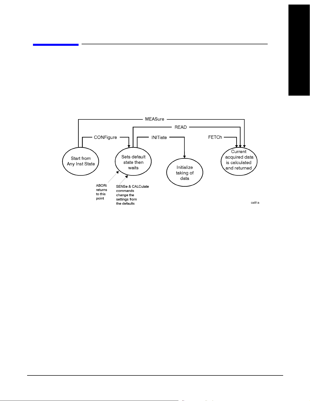
Front-Panel Key and SCPI Command Reference
3.4 Measure
Accesses the Measure menus.
3.4.1 Command Interactions: MEASure, CONFigure, FETCh, INITiate and READ
Figure 1 Measurement Group of Commands
Front-Panel Key and SCPI Command
Measure
Reference
Chapter 3
85

Front-Panel Key and SCPI Command Reference
Measure
Reference
Front-Panel Key and SCPI Command
Measure Commands:
:MEASure:<measurement>[n]?
This is a fast single-command way to make a measurement using the factory default
instrument settings. These are the settings and units that conform to the Mode Setup
settings (e.g. radio standard) that you have currently selected.
• Stops the current measurement (if any) and sets up the instrument for the specified
measurement using the factory defaults
• Initiates the data acquisition for the measurement
• Blocks other SCPI communication, waiting until the measurement is complete before
returning results.
• After the data is valid it returns the scalar results, or the trace data, for the specified
measurement. The type of data returned may be defined by an [n] value that is sent with the
command.
The scalar measurement results will be returned if the optional [n] value is not included, or is
set to 1. If the [n] value is set to a value other than 1, the selected trace data results will be
returned. See each command for details of what types of scalar results or trace data results
are available.
ASCII is the default format for the data output. (Older versions of Spectrum Analysis and
Phase Noise mode measurements only use ASCII.) The binary data formats should be used
for handling large blocks of data since they are smaller and faster than the ASCII format.
Refer to the FORMat:DATA command for more information.
If you need to change some of the measurement parameters from the factory default
settings you can set up the measurement with the CONFigure command. Use the
commands in the SENSe:<measurement> and CALCulate:<measurement> subsystems
to change the settings. Then you can use the READ? command to initiate the
measurement and query the results. See
Figure 1.
If you need to repeatedly make a given measurement with settings other than the
factory defaults, you can use the commands in the SENSe:<measurement> and
CALCulate:<measurement> subsystems to set up the measurement. Then use the
READ? command to initiate the measurement and query results.
Measurement settings persist if you initiate a different measurement and then return to
a previous one. Use READ:<measurement>? if you want to use those persistent settings.
If you want to go back to the default settings, use MEASure:<measurement>?.
Configure Commands:
:CONFigure:<measurement>
This command stops the current measurement (if any) and sets up the instrument for the
specified measurement using the factory default instrument settings. It sets the instrument to
single measurement mode but should not initiate the taking of measurement data unless
INIT:CONTinuous is ON. After you change any measurement settings, the READ command can
be used to initiate a measurement without changing the settings back to their defaults.
The CONFigure? query returns the current measurement name.
86
Chapter 3

Front-Panel Key and SCPI Command Reference
Measure
Fetch Commands:
:FETCh:<measurement>[n]?
This command puts selected data from the most recent measurement into the output buffer. Use
FETCh if you have already made a good measurement and you want to return several types of
data (different [n] values, e.g. both scalars and trace data) from a single measurement. FETCh
saves you the time of re-making the measurement. You can only FETCh results from the
measurement that is currently active, it will not change to a different measurement.
If you need to get new measurement data, use the READ command, which is equivalent to an
INITiate followed by a FETCh.
The scalar measurement results will be returned if the optional [n] value is not included, or is set
to 1. If the [n] value is set to a value other than 1, the selected trace data results will be returned.
See each command for details of what types of scalar results or trace data results are available.
The binary data formats should be used for handling large blocks of data since they are smaller
and transfer faster then the ASCII format. (FORMat:DATA)
FETCh may be used to return results other than those specified with the original READ
or MEASure command that you sent.
Front-Panel Key and SCPI Command
Reference
INITiate Commands:
:INITiate:<measurement>
This command is not available for measurements in all the instrument modes:
• Initiates a trigger cycle for the specified measurement, but does not output any data. You
must then use the FETCh<meas> command to return data. If a measurement other than the
current one is specified, the instrument will switch to that measurement and then initiate it.
For example, suppose you have previously initiated the ACP measurement, but now you are
running the channel power measurement. If you send INIT :ACP? it will change from channel
power to ACP and will initiate an ACP measurement.
• Does not change any of the measurement settings. For example, if you have previously
started the ACP measurement and you send INIT:ACP? it will initiate a new ACP
measurement using the same instrument settings as the last time ACP was run.
• If your selected measurement is currently active (in the idle state) it triggers the
measurement, assuming the trigger conditions are met. Then it completes one trigger
cycle. Depending upon the measurement and the number of averages, there may be
multiple data acquisitions, with multiple trigger events, for one full trigger cycle. It
also holds off additional commands on GPIB until the acquisition is complete.
Chapter 3
87

Front-Panel Key and SCPI Command Reference
Measure
READ Commands:
Reference
Front-Panel Key and SCPI Command
:READ:<measurement>[n]?
• Does not preset the measurement to the factory default settings. For example, if you have
previously initiated the ACP measurement and you send READ:ACP? it will initiate a new
measurement using the same instrument settings.
• Initiates the measurement and puts valid data into the output buffer . If a measurement other
than the current one is specified, the instrument will switch to that measurement before it
initiates the measurement and returns results.
For example, suppose you have previously initiated the ACP measurement, but now you are
running the channel power measurement. Then you send READ:ACP? It will change from
channel power back to ACP and, using the previous ACP settings, will initiate the
measurement and return results.
• Blocks other SCPI communication, waiting until the measurement is complete before
returning the results
If the optional [n] value is not included, or is set to 1, the scalar measurement results
will be returned. If the [n] value is set to a value other than 1, the selected trace data
results will be returned. See each command for details of what types of scalar results
or trace data results are available. The binary data formats should be used when
handling large blocks of data since they are smaller and faster then the ASCII
format. (FORMat:DATA)
3.4.2 Transmit Power
This key allows the user to switch to the Transmit Power measurement.
Mode: WLAN
Key Path:
Remote Command: See “SCPI Only Commands” on page 88
Example: CONF:TXP
MEASURE
3.4.2.1 SCPI Only Commands
:CONFigure:TXPower
:INITiate:TXPower
:FETCh:TXPower[n]?
:MEASure:TXPower[n]?
:READ:TXPower[n]?
88
Chapter 3

Front-Panel Key and SCPI Command Reference
Measure
Front-Panel Key and SCPI Command
Reference
Index: n
<Mnemonic>
0 Returns unprocessed I/Q trace data, as a series of comma-separated trace
not specified
or n = 1
Results Returned
points, in volts. The I values are listed first in each pair, using the 0
through even-indexed values. The Q values are the odd-indexed values.
Returns the following 5 values:
1. Transmit Power: (floating) [dBm]
The Transmit Power is the total power measured in the specified
integration bandwidth.
2. Power Spectral Dens ity: (floating) [dBm/MHz]
The power spectral density is the measured maximum transmit power
in 1MHz band width
3. Transmit Power Pass/Fail: (boolean)
1 for Pass; 0 for Fail
4. Power Spectral Dens ity Pass /Fa il : (boole an)
1 for Pass; 0 for Fail
5. Transmit Power & Power Spectral Density Pass/Fail: (boolean)
1 for Pass; 0 for Fail
2 Returns a series of floating point numbers that represent the powers at
those FFT points in the span bandwidth.
3.4.3 Modulation Accuracy
This key allows the user to switch to the Modulation Accuracy measurement.
Mode: WLAN
Key Path:
Remote Command: See “SCPI Only Commands” on page 89
Example: CONF:EVM
3.4.3.1 SCPI Only Commands
3.4.3.1.1 802.11a/g SCPI Only Commands
:CONFigure:EVM
:INITiate:EVM
:FETCh:EVM[n]?
MEASURE
:READ:EVM[n]?
Chapter 3
89

Front-Panel Key and SCPI Command Reference
Measure
:MEASure:EVM[n]?
Reference
Index: n
<Mnemonic
>
Results Returned
Front-Panel Key and SCPI Command
n = 0 Returns unprocessed I/Q trace data of Capture Interval, as a series of trace
point values. The I values are listed first in each pair, using the 0 through
even-indexed values. The Q values are the odd-indexed values.
Not specified
or n = 1
Returns the following 34 comma-separated scalar results:
“Avg” means the average of the individual measurements when averaging
is on.
“Max” means the maximum of the individual measurements when
averaging is on.
1. RMS EVM Max (dB)
2. RMS EVM Avg (dB)
3. Peak EVM Max (dB)
4. Peak EVM Avg (dB)
5. Max Peak EVM Index
6. Peak EVM Index
7. Frequency Error Max (Hz)
8. Frequency Error Avg (Hz)
9. Frequency Error Max (ppm)
10.Frequency Error Avg (ppm)
90
11.Symbol Clock Error Max (ppm)
12.Symbol Clock Error Avg (ppm)
13.I/Q Origin Offset Max (dB)
14.I/Q Origin Offset Avg (dB)
15.Gain Imbalance Max
16.Gain Imbalance Avg
17.Quadrature error Max (degrees)
18.Quadrature error Avg (degrees)
19.Reserved for 802.11b, returns –999.0
20.Reserved for 802.11b, returns –999.0
(Continued on next page)
Chapter 3

Front-Panel Key and SCPI Command Reference
Measure
Front-Panel Key and SCPI Command
Reference
Index: n
<Mnemonic
>
Not specified
or n = 1
(Cont’d)
Results Returned
21.Reserved for 802.11b, returns –999.0
22.Reserved for 802.11b, returns –999.0
23.Reserved for 802.11b, returns –999.0
24.Reserved for 802.11b, returns –999.0
25.Reserved for 802.11b, returns –999.0
26.Reserved for 802.11b, returns –999.0
27.Reserved for 802.11b, returns –999.0
28.Reserved for 802.11b, returns –999.0
29.Reserved for 802.11b, returns –999.0
30.Reserved for 802.11b, returns –999.0
31.Reserved for 802.11b, returns –999.0
32.Reserved for 802.11b, returns –999.0
33.Reserved for 802.11b, returns –999.0
34.Reserved for 802.11b, returns –999.0
n = 2 EVM vs. Symbol trace returns series of floating point numbers (in percent)
that represent each sample in the EVM vs. Symbol trace of Capture
Interval. The first number is the symbol 0 decision point.
n = 3 EVM vs. Carrier trace returns series of floating point numbers (in percent)
that represent each sample in the EVM vs. Carrier trace of Capture
Interval.
n = 7 Corrected measured trace returns series of floating point numbers that
alternately represent I and Q pairs of the corrected measured trace. The
magnitude of each I and Q pair are normalized to 1.0, when the IQ
Normalize is turned on. The first number is the in-phase (I) sample and the
second is the quadrature-phase (Q) sample.
n = 8 Returns Decoded Bits
n = 9 Returns 4 comma-separated scalar values of the pass/fail (0.0 = passed, or
1.0 = failed) results determined by testing the following items. And the
pass/fail is for the peak-hold value. Because the test on peak-hold value
should be greater than the average value, if it fails on the average, it will
fail on peak-hold.
1. Test result of RMS EVM
2. Test result of Frequency Error
3. Test result of symbol clock error
Chapter 3
4. Test result of I/Q Origin Offset
91

Front-Panel Key and SCPI Command Reference
Measure
3.4.3.1.2 802.11b/g SCPI Only Commands
See “802.11a/g SCPI Only Commands” on page 89.
Reference
Front-Panel Key and SCPI Command
Index: n
<Mnemonic
>
n = 0 Returns unprocessed I/Q trace data of Capture Interval, as a series of trace
Not specified
or n = 1
Results Returned
point values. The I values are listed first in each pair, using the 0 through
even-indexed values. The Q values are the odd-indexed values.
Returns the following 34 comma-separated scalar results:
“Avg” means the average of the individual measurements when averaging
is on.
“Max” means the maximum of the individual measurements when
averaging is on.
“Min” means the minimum of the individual measurements when
averaging is on.
1. RMS EVM Max (%)
2. RMS EVM Avg (%)
3. Peak EVM Max (%)
4. Peak EVM Avg (%)
5. Max Peak EVM Index
6. Peak EVM Index
7. Frequency Error Max (Hz)
8. Frequency Error Avg (Hz)
9. Frequency Error Max (ppm)
10.Frequency Error Avg (ppm)
11.Symbol Clock Error Max (ppm)
12.Symbol Clock Error Avg (ppm)
13.I/Q Origin Offset Max (dB)
14.I/Q Origin Offset Avg (dB)
15.Gain Imbalance Max
(Continued on next page)
92
Chapter 3

Front-Panel Key and SCPI Command Reference
Measure
Front-Panel Key and SCPI Command
Reference
Index: n
<Mnemonic
>
Not specified
or n=1
(Cont’d)
Results Returned
16.Gain Imbalance Avg
17.Quadrature error Max (degrees)
18.Quadrature error Avg (degrees)
19.1000chips Peak EVM Max (%)
20.1000 chips Peak EVM Avg (%)
21.RMS Magnitude Error Max (%)
22.RMS Magnitude Error Avg (%)
23.Peak Magnitude Error Max (%)
24.Peak Magnitude Error Avg (%)
25.Max Peak Magnitude Error Index
26.Peak Magnitude Error Index
27.RMS Phase Error Max (%)
28.RMS Phase Error Avg (%)
29.Peak Phase Error Max (%)
30.Peak Phase Error Avg (%)
31.Max Peak Phase Error Index
32.Peak Phase Error Index
33.Carrier suppression Min (dB)
34.Carrier suppression Avg (dB)
n = 4 EVM trace returns series of floating point numbers (in percent) that
represent EVM value for each chip in the measurement interval.
n = 5 Magnitude error trace returns series of floating point numbers (in percent)
that represent the magnitude error value for each chip in the measurement
interval.
n = 6 Phase error trace returns series of floating point numbers (in degrees) that
represent the phase error value for each chip in the measurement interval.
n = 7 Corrected measured trace returns series of floating point numbers that
alternately represent I and Q pairs of the corrected measured trace. The
magnitude of each I and Q pair are normalized to 1.0. The first number is
the in-phase (I) sample of symbol 0 decision point and the second is the
quadrature-phase (Q) sample of symbol 0 decision point.
n = 8 Returns Decoded Bits
Chapter 3
93

Front-Panel Key and SCPI Command Reference
Measure
Reference
Front-Panel Key and SCPI Command
Index: n
<Mnemonic
>
n = 9 Returns 5 comma-separated scalar values of the pass/fail (0.0 = passed, or
Results Returned
1.0 = failed) results determined by testing the following items. And the
pass/fail is for the peak-hold value. Because the test on peak-hold value
should be server than the average value. Regarding the case that it passes
on peak-hold but fails on the average, it definitely does not happen.
1. Test result of RMS EVM
2. Test result of 1000 Chips EVM
3. Test result of Frequency Error
4. Test result of RF Carrier Suppression
5. Test result of Chip clock error
3.4.4 Transmit Spectrum Mask
This key allows the user to switch to the Transmit Spectrum Mask measurement.
Mode: WLAN
Key Path:
Remote Command: See “SCPI Only Commands” on page 94
Example: CONF:SEM
MEASURE
3.4.4.1 SCPI Only Commands
:CONFigure:SEMask
:FETCh:SEMask[n]?
:MEASure:SEMask[n]?
:READ:SEMask[n]?
NOTE Offsets that are turned off (inactive) will return –999.0 when their results are
queried over SCPI.
94
Chapter 3

Front-Panel Key and SCPI Command Reference
Measure
Front-Panel Key and SCPI Command
Reference
Index: n
<Mnemonic>
not specified
or n = 1
Results Returned
Power Spectral Density Reference
Returns 60 comma-separated scalar results, in the following order:
1. Reserved for the future use, returns –999.0
2. Absolute power at the center frequency (reference) area (dBm)
3. Reserved for the future use, returns –999.0
4. Reserved for the future use, returns –999.0
5. Reserved for the future use, returns –999.0
6. Reserved for the future use, returns –999.0
7. Reserved for the future use, returns –999.0
8. Reserved for the future use, returns –999.0
9. Reserved for the future use, returns –999.0
10.Reserved for the future use, returns –999.0
11.Reserved for the future use, returns –999.0
12.Reserved for the future use, returns –999.0
13.Relative peak power spectral density on the negative offset A (dB/Hz)
14.Absolute peak power spectral density on the negative offset A (dBm/Hz)
15.Peak frequency in the negative offset A (Hz)
16.Reserved for the future use, returns –999.0
17.Reserved for the future use, returns –999.0
18.Relative peak power spectral density on the positive offset A (dB/Hz)
19.Absolute peak power spectral density on the positive offset A (dBm/Hz)
20.Peak frequency in the positive offset A (Hz)
21.Reserved for the future use, returns –999.0
22.Reserved for the future use, returns –999.0
23.Relative peak power spectral density on the negative offset B (dB/Hz)
24.Absolute peak power spectral density on the negative offset B (dBm/Hz)
25.Peak frequency in the negative offset B (Hz)
(Continued on next page)
Chapter 3
95

Front-Panel Key and SCPI Command Reference
Measure
Reference
Front-Panel Key and SCPI Command
Index: n
<Mnemonic>
not specified
or n = 1
(Cont’d)
Results Returned
Power Spectral Density Reference
Returns 60 comma-separated scalar results, in the following order:
26.Reserved for the future use, returns –999.0
27.Reserved for the future use, returns –999.0
28.Relative peak power spectral density on the positive offset B (dB/Hz)
29.Absolute peak power spectral density on the positive offset B (dBm/Hz)
30.Peak frequency in the positive offset B (Hz)
31.Reserved for the future use, returns –999.0
32.Reserved for the future use, returns –999.0
33.Relative peak power spectral density on the negative offset C (dB/Hz)
34.Absolute peak power spectral density on the negative offset C (dBm/Hz)
35.Peak frequency in the negative offset C (Hz)
36.Reserved for the future use, returns –999.0
37.Reserved for the future use, returns –999.0.
38.Relative peak power spectral density on the positive offset C (dB/Hz)
39.Absolute peak power spectral density on the positive offset C (dBm/Hz)
40.Peak frequency in the positive offset C (Hz)
41.Reserved for the future use, returns –999.0
42.Reserved for the future use, returns –999.0
43.Relative peak power spectral density on the negative offset D (dB/Hz)
44.Absolute peak power spectral density on the negative offset D (dBm/Hz)
45.Peak frequency in the negative offset D (Hz)
(Continued on next page)
96
Chapter 3

Front-Panel Key and SCPI Command Reference
Measure
Front-Panel Key and SCPI Command
Reference
Index: n
<Mnemonic>
not specified
or n = 1
(Cont’d)
Results Returned
Power Spectral Density Reference
Returns 60 comma-separated scalar results, in the following order:
46.Reserved for the future use, returns –999.0
47.Reserved for the future use, returns –999.0.
48.Relative peak power spectral density on the positive offset D (dB/Hz)
49.Absolute peak power spectral density on the positive offset D (dBm/Hz)
50.Peak frequency in the positive offset D (Hz)
51.Reserved for the future use, returns –999.0
52.Reserved for the future use, returns –999.0
53.Relative peak power spectral density on the negative offset E (dB/Hz)
54.Absolute peak power spectral density on the negative offset E (dBm/Hz)
55.Peak frequency in the negative offset E (Hz)
56.Reserved for the future use, returns –999.0
57.Reserved for the future use, returns –999.0
58.Relative peak power spectral density on the positive offset E (dB/Hz)
59.Absolute peak power spectral density on the positive offset E (dBm/Hz)
60.Peak frequency in the positive offset E (Hz)
2 Returns the displayed frequenc y domain spectrum trace data
separated by comma. The number of data is determined by the setting of the
trace points parameter
3 Returns the displayed frequenc y domain absolute limit trace
data separated by comma. The number of data is determined by the setting of
the trace points parameter
4 Returns the displayed frequency domain relative limit trace
data separated by comma. The number of data is determined by the setting of
the trace points parameter.
Chapter 3
97

Front-Panel Key and SCPI Command Reference
Measure
Reference
Front-Panel Key and SCPI Command
Index: n
Results Returned
<Mnemonic>
5 Power Spectral Density Reference
Returns 12 comma-separated scalar values (in dBm/Hz) of the absolute
power spectral density of the segment frequencies:
1. Absolute power spectral density reference (dBm/Hz)
2. Reserved for the future use, returns –999.0
3. Absolute power spectral density for negative offset frequency (A)
4. Absolute power spectral density for positive offset frequency (A)
5. Absolute power density for negative offset frequency (B)
6. Absolute power density for positive offset frequency (B)
7. Absolute power density for negative offset frequency (C)
8. Absolute power density for positive offset frequency (C)
9. Absolute power density for negative offset frequency (D)
10.Absolute power density for positive offset frequency (D)
11.Absolute power density for negative offset frequency (E)
12.Absolute power density for positive offset frequency (E)
6 Power Spectral Density Reference
Returns 12 comma-separated scalar values (in dB/Hz) of the power spectral
density relative to the carrier at the segment frequencies:
1. Relative power spectral density reference (dB/Hz)
2. Reserved for the future use, returns –999.0
3. Relative power spectral density for negative offset frequency (A)
4. Relative power spectral density for positive offset frequency (A)
5. Relative power spectral density for negative offset frequency (B)
6. Relative power spectral density for positive offset frequency (B)
7. Relative power spectral density for negative offset frequency (C)
8. Relative power spectral density for positive offset frequency (C)
9. Relative power spectral density for negative offset frequency (D)
10.Relative power spectral density for positive offset frequency (D)
11.Relative power spectral density for negative offset frequency (E)
12.Relative power spectral density for positive offset frequency (E)
98
Chapter 3

Front-Panel Key and SCPI Command Reference
Measure
Front-Panel Key and SCPI Command
Reference
Index: n
Results Returned
<Mnemonic>
7 Returns 12 comma-separated pass/fail test results (0 = passed, or 1 = failed)
determined by testing the absolute power spectral density of the offset
frequencies:
1. 1. Reserved for the future use, returns –999.0
2. Reserved for the future use, returns –999.0
3. For negative offset frequency (A)
4. For positive offset frequency (A)
5. For negative offset frequency (B)
6. For positive offset frequency (B)
7. For negative offset frequency (C)
8. For positive offset frequency (C)
9. For negative offset frequency (D)
10.For positive offset frequency (D)
11.For negative offset frequency (E)
12.For positive offset frequency (E)
8 Returns 12 comma-separated scalar values of the pass/fail (0=passed, or
1=failed) results determined by testing the power spectral density of the
segment frequencies relative to reference channel:
1. Reserved for the future use, returns –999.0
2. Reserved for the future use, returns –999.0
3. For negative offset frequency (A)
4. For positive offset frequency (A)
5. For negative offset frequency (B)
6. For positive offset frequency (B)
7. For negative offset frequency (C)
8. For positive offset frequency (C)
9. For negative offset frequency (D)
10.For positive offset frequency (D)
11.For negative offset frequency (E)
12.For positive offset frequency (E)
Chapter 3
99

Front-Panel Key and SCPI Command Reference
Measure
Reference
Front-Panel Key and SCPI Command
Index: n
<Mnemonic>
9 Returns 12 comma-separated scalar values of frequency (in Hz) that have
10 Returns the band power result
Results Returned
peak power in each offset:
1. Reserved for the future use, returns –999.0
2. Reserved for the future use, returns –999.0
3. For negative offset frequency (A)
4. For positive offset frequency (A)
5. For negative offset frequency (B)
6. For positive offset frequency (B)
7. For negative offset frequency (C)
8. For positive offset frequency (C)
9. For negative offset frequency (D)
10.For positive offset frequency (D)
11.For negative offset frequency (E)
12.For positive offset frequency (E)
3.4.5 Power vs. Time
This key allows the user to switch to the Power vs. Time measurement.
Mode: WLAN
Key Path:
Remote Command: See “SCPI Only Commands” on page 100
Example: CONF:PVT
3.4.5.1 SCPI Only Commands
:CONFigure:PVTime
:INITiate: PVTime
:FETCh: PVTime [n]?
:MEASure: PVTime [n]?
:READ: PVTime [n]?
MEASURE
100
Chapter 3
 Loading...