


TD-SCDMA Power Measurement Guide
Agilent Technologies PSA Series
Option 211
This manual provides documentation for the following instruments:
Spectrum Analyzers:
E4440A (3 Hz – 26.5 GHz)
E4443A (3 Hz – 6.7 GHz)
E4445A (3 Hz – 13.2 GHz)
E4446A (3 Hz – 44.0 GHz)
E4447A (3 Hz – 42.98 GHz)
E4448A (3 Hz – 50.0 GHz)
Manufacturing Part Number: E4440-90622
Supersedes E4440-90340
Printed in USA
June 2008
© Copyright 2006, 2008 Agilent Technologies, Inc.

The information contained in this document is subject to change without notice.
Agilent Technologies makes no warranty of any kind with regard to this material,
including but not limited to, the implied warranties of merchantability and fitness
for a particular purpose. Agilent Technologies shall not be liable for errors
contained herein or for incidental or consequential damages in connection with the
furnishing, performance, or use of this material.
2

Contents
1. Introduction
What Does the Agilent PSA Series and
Option 211 Do?. . . . . . . . . . . . . . . . . . . . . . . . . . . . . . . . . . . . . . . . . . . . . . . . . . . . . . . . . . . . . . . . . . . . . . . 24
Installing Optional Measurement Personalities . . . . . . . . . . . . . . . . . . . . . . . . . . . . . . . . . . . . . . . . . . . . . . 26
Do You Have Enough Memory to Load All Your Personality Options? . . . . . . . . . . . . . . . . . . . . . . . . . 26
How to Predict Your Memory Requirements . . . . . . . . . . . . . . . . . . . . . . . . . . . . . . . . . . . . . . . . . . . . . . 28
Measurement Personality Options and Memory Required . . . . . . . . . . . . . . . . . . . . . . . . . . . . . . . . . . 28
Memory Upgrade Kits. . . . . . . . . . . . . . . . . . . . . . . . . . . . . . . . . . . . . . . . . . . . . . . . . . . . . . . . . . . . . . 30
Loading an Optional Measurement Personality . . . . . . . . . . . . . . . . . . . . . . . . . . . . . . . . . . . . . . . . . . . . 30
Obtaining and Installing a License Key . . . . . . . . . . . . . . . . . . . . . . . . . . . . . . . . . . . . . . . . . . . . . . . . . . 30
Viewing a License Key . . . . . . . . . . . . . . . . . . . . . . . . . . . . . . . . . . . . . . . . . . . . . . . . . . . . . . . . . . . . . . . 31
Using the Delete License Key on PSA . . . . . . . . . . . . . . . . . . . . . . . . . . . . . . . . . . . . . . . . . . . . . . . . . . . 31
Ordering Optional Measurement Personalities . . . . . . . . . . . . . . . . . . . . . . . . . . . . . . . . . . . . . . . . . . . . . 32
2. Making Measurements
TD-SCDMA Measurements . . . . . . . . . . . . . . . . . . . . . . . . . . . . . . . . . . . . . . . . . . . . . . . . . . . . . . . . . . . . . 34
Setting up and Making a Measurement . . . . . . . . . . . . . . . . . . . . . . . . . . . . . . . . . . . . . . . . . . . . . . . . . . . . 35
Making the Initial Signal Connection . . . . . . . . . . . . . . . . . . . . . . . . . . . . . . . . . . . . . . . . . . . . . . . . . . . . 35
Using Instrument Mode and Measurement Presets. . . . . . . . . . . . . . . . . . . . . . . . . . . . . . . . . . . . . . . . . . 35
The 3 Steps to Set Up and Make Measurements. . . . . . . . . . . . . . . . . . . . . . . . . . . . . . . . . . . . . . . . . . . . 36
Preparing for Measurements. . . . . . . . . . . . . . . . . . . . . . . . . . . . . . . . . . . . . . . . . . . . . . . . . . . . . . . . . . . . . 37
Initial Setup . . . . . . . . . . . . . . . . . . . . . . . . . . . . . . . . . . . . . . . . . . . . . . . . . . . . . . . . . . . . . . . . . . . . . . . . 37
Transmit Power Measurement . . . . . . . . . . . . . . . . . . . . . . . . . . . . . . . . . . . . . . . . . . . . . . . . . . . . . . . . . . . 38
One-Button BTS Measurement Procedure . . . . . . . . . . . . . . . . . . . . . . . . . . . . . . . . . . . . . . . . . . . . . . . . 38
Measurement Results . . . . . . . . . . . . . . . . . . . . . . . . . . . . . . . . . . . . . . . . . . . . . . . . . . . . . . . . . . . . . . . . 39
Troubleshooting Hints. . . . . . . . . . . . . . . . . . . . . . . . . . . . . . . . . . . . . . . . . . . . . . . . . . . . . . . . . . . . . . . . 43
Power Versus Time Measurement. . . . . . . . . . . . . . . . . . . . . . . . . . . . . . . . . . . . . . . . . . . . . . . . . . . . . . . . . 44
One-Button BTS Measurement Procedure . . . . . . . . . . . . . . . . . . . . . . . . . . . . . . . . . . . . . . . . . . . . . . . . 44
Measurement Results . . . . . . . . . . . . . . . . . . . . . . . . . . . . . . . . . . . . . . . . . . . . . . . . . . . . . . . . . . . . . . . . 46
Troubleshooting Hints. . . . . . . . . . . . . . . . . . . . . . . . . . . . . . . . . . . . . . . . . . . . . . . . . . . . . . . . . . . . . . . . 48
ACP (ACLR) Measurement . . . . . . . . . . . . . . . . . . . . . . . . . . . . . . . . . . . . . . . . . . . . . . . . . . . . . . . . . . . . . 49
One-Button MS Measurement Procedure . . . . . . . . . . . . . . . . . . . . . . . . . . . . . . . . . . . . . . . . . . . . . . . . . 49
Measurement Results . . . . . . . . . . . . . . . . . . . . . . . . . . . . . . . . . . . . . . . . . . . . . . . . . . . . . . . . . . . . . . . . 50
Troubleshooting Hints. . . . . . . . . . . . . . . . . . . . . . . . . . . . . . . . . . . . . . . . . . . . . . . . . . . . . . . . . . . . . . . . 52
Multi-Carrier Power Measurement. . . . . . . . . . . . . . . . . . . . . . . . . . . . . . . . . . . . . . . . . . . . . . . . . . . . . . . . 53
One-Button BTS Measurement Procedure . . . . . . . . . . . . . . . . . . . . . . . . . . . . . . . . . . . . . . . . . . . . . . . . 53
Measurement Results . . . . . . . . . . . . . . . . . . . . . . . . . . . . . . . . . . . . . . . . . . . . . . . . . . . . . . . . . . . . . . . . 54
Troubleshooting Hints. . . . . . . . . . . . . . . . . . . . . . . . . . . . . . . . . . . . . . . . . . . . . . . . . . . . . . . . . . . . . . . . 56
Spurious Emissions Measurement . . . . . . . . . . . . . . . . . . . . . . . . . . . . . . . . . . . . . . . . . . . . . . . . . . . . . . . . 57
One-Button MS Measurement Procedure . . . . . . . . . . . . . . . . . . . . . . . . . . . . . . . . . . . . . . . . . . . . . . . . . 57
Measurement Results . . . . . . . . . . . . . . . . . . . . . . . . . . . . . . . . . . . . . . . . . . . . . . . . . . . . . . . . . . . . . . . . 59
Troubleshooting Hints. . . . . . . . . . . . . . . . . . . . . . . . . . . . . . . . . . . . . . . . . . . . . . . . . . . . . . . . . . . . . . . . 59
Spectrum Emission Mask (SEM) Measurement. . . . . . . . . . . . . . . . . . . . . . . . . . . . . . . . . . . . . . . . . . . . . . 60
One-Button MS Measurement Procedure . . . . . . . . . . . . . . . . . . . . . . . . . . . . . . . . . . . . . . . . . . . . . . . . . 60
Measurement Results . . . . . . . . . . . . . . . . . . . . . . . . . . . . . . . . . . . . . . . . . . . . . . . . . . . . . . . . . . . . . . . . 61
Troubleshooting Hints. . . . . . . . . . . . . . . . . . . . . . . . . . . . . . . . . . . . . . . . . . . . . . . . . . . . . . . . . . . . . . . . 63
Occupied Bandwidth Measurement . . . . . . . . . . . . . . . . . . . . . . . . . . . . . . . . . . . . . . . . . . . . . . . . . . . . . . . 64
One-Button MS Measurement Procedure . . . . . . . . . . . . . . . . . . . . . . . . . . . . . . . . . . . . . . . . . . . . . . . . . 64
Measurement Results . . . . . . . . . . . . . . . . . . . . . . . . . . . . . . . . . . . . . . . . . . . . . . . . . . . . . . . . . . . . . . . . 66
Table of Contents
3

Contents
Table of Contents
3. Key and SCPI Reference
Troubleshooting Hints. . . . . . . . . . . . . . . . . . . . . . . . . . . . . . . . . . . . . . . . . . . . . . . . . . . . . . . . . . . . . . . . 67
Using Basic Mode . . . . . . . . . . . . . . . . . . . . . . . . . . . . . . . . . . . . . . . . . . . . . . . . . . . . . . . . . . . . . . . . . . . . 68
Basic Mode in PSA Series Spectrum Analyzers . . . . . . . . . . . . . . . . . . . . . . . . . . . . . . . . . . . . . . . . . . . 68
Instrument Front Panel Highlights . . . . . . . . . . . . . . . . . . . . . . . . . . . . . . . . . . . . . . . . . . . . . . . . . . . . . . . . 70
Common Functionality. . . . . . . . . . . . . . . . . . . . . . . . . . . . . . . . . . . . . . . . . . . . . . . . . . . . . . . . . . . . . . . . . 72
Mode Switching . . . . . . . . . . . . . . . . . . . . . . . . . . . . . . . . . . . . . . . . . . . . . . . . . . . . . . . . . . . . . . . . . . . . 72
Mode Selection on Power On/Preset . . . . . . . . . . . . . . . . . . . . . . . . . . . . . . . . . . . . . . . . . . . . . . . . . . 72
TD-SCDMA Mode Entry . . . . . . . . . . . . . . . . . . . . . . . . . . . . . . . . . . . . . . . . . . . . . . . . . . . . . . . . . . . 72
TD-SCDMA Mode Exit . . . . . . . . . . . . . . . . . . . . . . . . . . . . . . . . . . . . . . . . . . . . . . . . . . . . . . . . . . . . 72
Mode Menu. . . . . . . . . . . . . . . . . . . . . . . . . . . . . . . . . . . . . . . . . . . . . . . . . . . . . . . . . . . . . . . . . . . . . . 72
Remote Control. . . . . . . . . . . . . . . . . . . . . . . . . . . . . . . . . . . . . . . . . . . . . . . . . . . . . . . . . . . . . . . . . . . 73
Mode Setup Menu . . . . . . . . . . . . . . . . . . . . . . . . . . . . . . . . . . . . . . . . . . . . . . . . . . . . . . . . . . . . . . . . . . 74
Radio Menu. . . . . . . . . . . . . . . . . . . . . . . . . . . . . . . . . . . . . . . . . . . . . . . . . . . . . . . . . . . . . . . . . . . . . . 74
Input Functions . . . . . . . . . . . . . . . . . . . . . . . . . . . . . . . . . . . . . . . . . . . . . . . . . . . . . . . . . . . . . . . . . . . 74
Trigger Functions . . . . . . . . . . . . . . . . . . . . . . . . . . . . . . . . . . . . . . . . . . . . . . . . . . . . . . . . . . . . . . . . . 78
Sweep Functions . . . . . . . . . . . . . . . . . . . . . . . . . . . . . . . . . . . . . . . . . . . . . . . . . . . . . . . . . . . . . . . . . . 80
Screen Layout Details. . . . . . . . . . . . . . . . . . . . . . . . . . . . . . . . . . . . . . . . . . . . . . . . . . . . . . . . . . . . . . . . 85
Annunciators. . . . . . . . . . . . . . . . . . . . . . . . . . . . . . . . . . . . . . . . . . . . . . . . . . . . . . . . . . . . . . . . . . . . . 85
Next Window / Zoom Front-panel keys . . . . . . . . . . . . . . . . . . . . . . . . . . . . . . . . . . . . . . . . . . . . . . . . 86
UI Integration with Base Instrument . . . . . . . . . . . . . . . . . . . . . . . . . . . . . . . . . . . . . . . . . . . . . . . . . . . . 88
Parameter Types . . . . . . . . . . . . . . . . . . . . . . . . . . . . . . . . . . . . . . . . . . . . . . . . . . . . . . . . . . . . . . . . . . . . 88
Status Reporting . . . . . . . . . . . . . . . . . . . . . . . . . . . . . . . . . . . . . . . . . . . . . . . . . . . . . . . . . . . . . . . . . . . . 89
STATus Subsystem . . . . . . . . . . . . . . . . . . . . . . . . . . . . . . . . . . . . . . . . . . . . . . . . . . . . . . . . . . . . . . . . 90
Other Common Menus . . . . . . . . . . . . . . . . . . . . . . . . . . . . . . . . . . . . . . . . . . . . . . . . . . . . . . . . . . . . . . . 91
File/Save Functions. . . . . . . . . . . . . . . . . . . . . . . . . . . . . . . . . . . . . . . . . . . . . . . . . . . . . . . . . . . . . . . . 91
Frequency Functions. . . . . . . . . . . . . . . . . . . . . . . . . . . . . . . . . . . . . . . . . . . . . . . . . . . . . . . . . . . . . . . 91
Span Functions . . . . . . . . . . . . . . . . . . . . . . . . . . . . . . . . . . . . . . . . . . . . . . . . . . . . . . . . . . . . . . . . . . . 95
Markers . . . . . . . . . . . . . . . . . . . . . . . . . . . . . . . . . . . . . . . . . . . . . . . . . . . . . . . . . . . . . . . . . . . . . . . . . . . 95
FORMat Subsystem . . . . . . . . . . . . . . . . . . . . . . . . . . . . . . . . . . . . . . . . . . . . . . . . . . . . . . . . . . . . . . . . . 95
Byte Order. . . . . . . . . . . . . . . . . . . . . . . . . . . . . . . . . . . . . . . . . . . . . . . . . . . . . . . . . . . . . . . . . . . . . . . 95
Trace Data Format . . . . . . . . . . . . . . . . . . . . . . . . . . . . . . . . . . . . . . . . . . . . . . . . . . . . . . . . . . . . . . . . 96
Measurement Display Availability . . . . . . . . . . . . . . . . . . . . . . . . . . . . . . . . . . . . . . . . . . . . . . . . . . . . . . 97
Measurements. . . . . . . . . . . . . . . . . . . . . . . . . . . . . . . . . . . . . . . . . . . . . . . . . . . . . . . . . . . . . . . . . . . . . . . . 98
Measure Menu . . . . . . . . . . . . . . . . . . . . . . . . . . . . . . . . . . . . . . . . . . . . . . . . . . . . . . . . . . . . . . . . . . . . . 98
Restart Measurement . . . . . . . . . . . . . . . . . . . . . . . . . . . . . . . . . . . . . . . . . . . . . . . . . . . . . . . . . . . . . . 98
Continuous vs. Single Measurement Mode . . . . . . . . . . . . . . . . . . . . . . . . . . . . . . . . . . . . . . . . . . . . . 98
Pause / Resume Measurement . . . . . . . . . . . . . . . . . . . . . . . . . . . . . . . . . . . . . . . . . . . . . . . . . . . . . . . 98
Single Front-panel key . . . . . . . . . . . . . . . . . . . . . . . . . . . . . . . . . . . . . . . . . . . . . . . . . . . . . . . . . . . . . 99
Remote Control. . . . . . . . . . . . . . . . . . . . . . . . . . . . . . . . . . . . . . . . . . . . . . . . . . . . . . . . . . . . . . . . . . . 99
Transmit Power . . . . . . . . . . . . . . . . . . . . . . . . . . . . . . . . . . . . . . . . . . . . . . . . . . . . . . . . . . . . . . . . . . . . . 105
Measurement Setup. . . . . . . . . . . . . . . . . . . . . . . . . . . . . . . . . . . . . . . . . . . . . . . . . . . . . . . . . . . . . . . . . 105
Meas Setup Menu . . . . . . . . . . . . . . . . . . . . . . . . . . . . . . . . . . . . . . . . . . . . . . . . . . . . . . . . . . . . . . . . 105
Marker Functions . . . . . . . . . . . . . . . . . . . . . . . . . . . . . . . . . . . . . . . . . . . . . . . . . . . . . . . . . . . . . . . . 111
Amplitude / Y Scale . . . . . . . . . . . . . . . . . . . . . . . . . . . . . . . . . . . . . . . . . . . . . . . . . . . . . . . . . . . . . . 113
Restore Meas Defaults . . . . . . . . . . . . . . . . . . . . . . . . . . . . . . . . . . . . . . . . . . . . . . . . . . . . . . . . . . . . 114
Restart Parameters . . . . . . . . . . . . . . . . . . . . . . . . . . . . . . . . . . . . . . . . . . . . . . . . . . . . . . . . . . . . . . . 114
Measurement Results . . . . . . . . . . . . . . . . . . . . . . . . . . . . . . . . . . . . . . . . . . . . . . . . . . . . . . . . . . . . . . . 114
4

Contents
Transmit Power . . . . . . . . . . . . . . . . . . . . . . . . . . . . . . . . . . . . . . . . . . . . . . . . . . . . . . . . . . . . . . . . . . 114
Max Pt (Current) . . . . . . . . . . . . . . . . . . . . . . . . . . . . . . . . . . . . . . . . . . . . . . . . . . . . . . . . . . . . . . . . . 114
Min Pt (Current) . . . . . . . . . . . . . . . . . . . . . . . . . . . . . . . . . . . . . . . . . . . . . . . . . . . . . . . . . . . . . . . . . 114
Mean Transmit Pwr (Current). . . . . . . . . . . . . . . . . . . . . . . . . . . . . . . . . . . . . . . . . . . . . . . . . . . . . . . 114
Burst Width . . . . . . . . . . . . . . . . . . . . . . . . . . . . . . . . . . . . . . . . . . . . . . . . . . . . . . . . . . . . . . . . . . . . . 115
Results . . . . . . . . . . . . . . . . . . . . . . . . . . . . . . . . . . . . . . . . . . . . . . . . . . . . . . . . . . . . . . . . . . . . . . . . . . . 115
Results Screen . . . . . . . . . . . . . . . . . . . . . . . . . . . . . . . . . . . . . . . . . . . . . . . . . . . . . . . . . . . . . . . . . . . 115
Results File . . . . . . . . . . . . . . . . . . . . . . . . . . . . . . . . . . . . . . . . . . . . . . . . . . . . . . . . . . . . . . . . . . . . . 117
Status Bar Messages . . . . . . . . . . . . . . . . . . . . . . . . . . . . . . . . . . . . . . . . . . . . . . . . . . . . . . . . . . . . . . . . 118
SCPI Remote Commands . . . . . . . . . . . . . . . . . . . . . . . . . . . . . . . . . . . . . . . . . . . . . . . . . . . . . . . . . . . . 119
Power vs Time . . . . . . . . . . . . . . . . . . . . . . . . . . . . . . . . . . . . . . . . . . . . . . . . . . . . . . . . . . . . . . . . . . . . . . 120
Measurement Setup . . . . . . . . . . . . . . . . . . . . . . . . . . . . . . . . . . . . . . . . . . . . . . . . . . . . . . . . . . . . . . . . . 120
Meas Setup Menu . . . . . . . . . . . . . . . . . . . . . . . . . . . . . . . . . . . . . . . . . . . . . . . . . . . . . . . . . . . . . . . . 120
Display Functions . . . . . . . . . . . . . . . . . . . . . . . . . . . . . . . . . . . . . . . . . . . . . . . . . . . . . . . . . . . . . . . . 128
Marker Functions . . . . . . . . . . . . . . . . . . . . . . . . . . . . . . . . . . . . . . . . . . . . . . . . . . . . . . . . . . . . . . . . 130
Span / X Scale Menu. . . . . . . . . . . . . . . . . . . . . . . . . . . . . . . . . . . . . . . . . . . . . . . . . . . . . . . . . . . . . . 132
Amplitude / Y Scale . . . . . . . . . . . . . . . . . . . . . . . . . . . . . . . . . . . . . . . . . . . . . . . . . . . . . . . . . . . . . . 133
Query the Pass/Fail state . . . . . . . . . . . . . . . . . . . . . . . . . . . . . . . . . . . . . . . . . . . . . . . . . . . . . . . . . . 134
Restart Parameters. . . . . . . . . . . . . . . . . . . . . . . . . . . . . . . . . . . . . . . . . . . . . . . . . . . . . . . . . . . . . . . . 134
Restore Meas Defaults . . . . . . . . . . . . . . . . . . . . . . . . . . . . . . . . . . . . . . . . . . . . . . . . . . . . . . . . . . . . 135
Results . . . . . . . . . . . . . . . . . . . . . . . . . . . . . . . . . . . . . . . . . . . . . . . . . . . . . . . . . . . . . . . . . . . . . . . . . . . 135
Measurement Results . . . . . . . . . . . . . . . . . . . . . . . . . . . . . . . . . . . . . . . . . . . . . . . . . . . . . . . . . . . . . 135
Results Screen . . . . . . . . . . . . . . . . . . . . . . . . . . . . . . . . . . . . . . . . . . . . . . . . . . . . . . . . . . . . . . . . . . . 137
Zoomed Results Screen. . . . . . . . . . . . . . . . . . . . . . . . . . . . . . . . . . . . . . . . . . . . . . . . . . . . . . . . . . . . 137
Results File . . . . . . . . . . . . . . . . . . . . . . . . . . . . . . . . . . . . . . . . . . . . . . . . . . . . . . . . . . . . . . . . . . . . . 138
Status Bar Messages . . . . . . . . . . . . . . . . . . . . . . . . . . . . . . . . . . . . . . . . . . . . . . . . . . . . . . . . . . . . . . . . 139
SCPI Remote Commands . . . . . . . . . . . . . . . . . . . . . . . . . . . . . . . . . . . . . . . . . . . . . . . . . . . . . . . . . . . . 139
Adjacent Channel Power Ratio (ACPR). . . . . . . . . . . . . . . . . . . . . . . . . . . . . . . . . . . . . . . . . . . . . . . . . . . 142
Measurement Setup . . . . . . . . . . . . . . . . . . . . . . . . . . . . . . . . . . . . . . . . . . . . . . . . . . . . . . . . . . . . . . . . . 142
Meas Setup Menu . . . . . . . . . . . . . . . . . . . . . . . . . . . . . . . . . . . . . . . . . . . . . . . . . . . . . . . . . . . . . . . . 142
Query the Pass/Fail state . . . . . . . . . . . . . . . . . . . . . . . . . . . . . . . . . . . . . . . . . . . . . . . . . . . . . . . . . . . 153
Restart Parameters. . . . . . . . . . . . . . . . . . . . . . . . . . . . . . . . . . . . . . . . . . . . . . . . . . . . . . . . . . . . . . . . 153
Marker Menu. . . . . . . . . . . . . . . . . . . . . . . . . . . . . . . . . . . . . . . . . . . . . . . . . . . . . . . . . . . . . . . . . . . . 153
Span / X Scale Menu. . . . . . . . . . . . . . . . . . . . . . . . . . . . . . . . . . . . . . . . . . . . . . . . . . . . . . . . . . . . . . 153
Amplitude / Y Scale . . . . . . . . . . . . . . . . . . . . . . . . . . . . . . . . . . . . . . . . . . . . . . . . . . . . . . . . . . . . . . 154
Results . . . . . . . . . . . . . . . . . . . . . . . . . . . . . . . . . . . . . . . . . . . . . . . . . . . . . . . . . . . . . . . . . . . . . . . . . . . 155
Results Screens . . . . . . . . . . . . . . . . . . . . . . . . . . . . . . . . . . . . . . . . . . . . . . . . . . . . . . . . . . . . . . . . . . 155
Results File. . . . . . . . . . . . . . . . . . . . . . . . . . . . . . . . . . . . . . . . . . . . . . . . . . . . . . . . . . . . . . . . . . . . . 156
SCPI Remote Commands . . . . . . . . . . . . . . . . . . . . . . . . . . . . . . . . . . . . . . . . . . . . . . . . . . . . . . . . . . . . 160
Multi-Carrier Power (MCP) . . . . . . . . . . . . . . . . . . . . . . . . . . . . . . . . . . . . . . . . . . . . . . . . . . . . . . . . . . . . 161
Measurement Setup . . . . . . . . . . . . . . . . . . . . . . . . . . . . . . . . . . . . . . . . . . . . . . . . . . . . . . . . . . . . . . . . . 161
Meas Setup Menu . . . . . . . . . . . . . . . . . . . . . . . . . . . . . . . . . . . . . . . . . . . . . . . . . . . . . . . . . . . . . . . . 161
Query the Pass/Fail state . . . . . . . . . . . . . . . . . . . . . . . . . . . . . . . . . . . . . . . . . . . . . . . . . . . . . . . . . . . 176
Restart Parameters. . . . . . . . . . . . . . . . . . . . . . . . . . . . . . . . . . . . . . . . . . . . . . . . . . . . . . . . . . . . . . . . 176
Marker Menu. . . . . . . . . . . . . . . . . . . . . . . . . . . . . . . . . . . . . . . . . . . . . . . . . . . . . . . . . . . . . . . . . . . . 176
Span / X Scale Menu. . . . . . . . . . . . . . . . . . . . . . . . . . . . . . . . . . . . . . . . . . . . . . . . . . . . . . . . . . . . . . 176
Amplitude / Y Scale . . . . . . . . . . . . . . . . . . . . . . . . . . . . . . . . . . . . . . . . . . . . . . . . . . . . . . . . . . . . . . 176
Restore Meas Defaults . . . . . . . . . . . . . . . . . . . . . . . . . . . . . . . . . . . . . . . . . . . . . . . . . . . . . . . . . . . . 177
Results . . . . . . . . . . . . . . . . . . . . . . . . . . . . . . . . . . . . . . . . . . . . . . . . . . . . . . . . . . . . . . . . . . . . . . . . . . . 177
Table of Contents
5

Contents
Table of Contents
Measurement Results . . . . . . . . . . . . . . . . . . . . . . . . . . . . . . . . . . . . . . . . . . . . . . . . . . . . . . . . . . . . . 177
Spectrum View . . . . . . . . . . . . . . . . . . . . . . . . . . . . . . . . . . . . . . . . . . . . . . . . . . . . . . . . . . . . . . . . . . 179
Combined View . . . . . . . . . . . . . . . . . . . . . . . . . . . . . . . . . . . . . . . . . . . . . . . . . . . . . . . . . . . . . . . . . 180
Results File . . . . . . . . . . . . . . . . . . . . . . . . . . . . . . . . . . . . . . . . . . . . . . . . . . . . . . . . . . . . . . . . . . . . . 180
SCPI Remote Commands . . . . . . . . . . . . . . . . . . . . . . . . . . . . . . . . . . . . . . . . . . . . . . . . . . . . . . . . . . . . 183
Spurious Emissions . . . . . . . . . . . . . . . . . . . . . . . . . . . . . . . . . . . . . . . . . . . . . . . . . . . . . . . . . . . . . . . . . . 184
Measurement Setup. . . . . . . . . . . . . . . . . . . . . . . . . . . . . . . . . . . . . . . . . . . . . . . . . . . . . . . . . . . . . . . . . 184
Meas Setup Menu . . . . . . . . . . . . . . . . . . . . . . . . . . . . . . . . . . . . . . . . . . . . . . . . . . . . . . . . . . . . . . . . 184
Range Table Description. . . . . . . . . . . . . . . . . . . . . . . . . . . . . . . . . . . . . . . . . . . . . . . . . . . . . . . . . . . 196
Marker Menu . . . . . . . . . . . . . . . . . . . . . . . . . . . . . . . . . . . . . . . . . . . . . . . . . . . . . . . . . . . . . . . . . . . 197
Span / X Scale Menu . . . . . . . . . . . . . . . . . . . . . . . . . . . . . . . . . . . . . . . . . . . . . . . . . . . . . . . . . . . . . 197
Amplitude / Y Scale Functions. . . . . . . . . . . . . . . . . . . . . . . . . . . . . . . . . . . . . . . . . . . . . . . . . . . . . . 197
Couplings . . . . . . . . . . . . . . . . . . . . . . . . . . . . . . . . . . . . . . . . . . . . . . . . . . . . . . . . . . . . . . . . . . . . . . 198
Query the Pass/Fail state . . . . . . . . . . . . . . . . . . . . . . . . . . . . . . . . . . . . . . . . . . . . . . . . . . . . . . . . . . 198
Restart Parameters . . . . . . . . . . . . . . . . . . . . . . . . . . . . . . . . . . . . . . . . . . . . . . . . . . . . . . . . . . . . . . . 199
Restore Meas Defaults . . . . . . . . . . . . . . . . . . . . . . . . . . . . . . . . . . . . . . . . . . . . . . . . . . . . . . . . . . . . 199
Results. . . . . . . . . . . . . . . . . . . . . . . . . . . . . . . . . . . . . . . . . . . . . . . . . . . . . . . . . . . . . . . . . . . . . . . . . . . 199
Meas Results File . . . . . . . . . . . . . . . . . . . . . . . . . . . . . . . . . . . . . . . . . . . . . . . . . . . . . . . . . . . . . . . . 200
Status Bar Messages . . . . . . . . . . . . . . . . . . . . . . . . . . . . . . . . . . . . . . . . . . . . . . . . . . . . . . . . . . . . . . . . 205
SCPI Remote Commands . . . . . . . . . . . . . . . . . . . . . . . . . . . . . . . . . . . . . . . . . . . . . . . . . . . . . . . . . . . . 206
Spectrum Emissions Mask . . . . . . . . . . . . . . . . . . . . . . . . . . . . . . . . . . . . . . . . . . . . . . . . . . . . . . . . . . . . 207
Measurement Setup. . . . . . . . . . . . . . . . . . . . . . . . . . . . . . . . . . . . . . . . . . . . . . . . . . . . . . . . . . . . . . . . . 207
Meas Setup Menu . . . . . . . . . . . . . . . . . . . . . . . . . . . . . . . . . . . . . . . . . . . . . . . . . . . . . . . . . . . . . . . . 207
Query the Pass/Fail state. . . . . . . . . . . . . . . . . . . . . . . . . . . . . . . . . . . . . . . . . . . . . . . . . . . . . . . . . . . 222
Restart Parameters . . . . . . . . . . . . . . . . . . . . . . . . . . . . . . . . . . . . . . . . . . . . . . . . . . . . . . . . . . . . . . . 222
Display Menu . . . . . . . . . . . . . . . . . . . . . . . . . . . . . . . . . . . . . . . . . . . . . . . . . . . . . . . . . . . . . . . . . . . 222
Marker Functions . . . . . . . . . . . . . . . . . . . . . . . . . . . . . . . . . . . . . . . . . . . . . . . . . . . . . . . . . . . . . . . . 222
Span / X Scale Menu . . . . . . . . . . . . . . . . . . . . . . . . . . . . . . . . . . . . . . . . . . . . . . . . . . . . . . . . . . . . . 224
Amplitude / Y Scale . . . . . . . . . . . . . . . . . . . . . . . . . . . . . . . . . . . . . . . . . . . . . . . . . . . . . . . . . . . . . . 224
Restore Meas Defaults . . . . . . . . . . . . . . . . . . . . . . . . . . . . . . . . . . . . . . . . . . . . . . . . . . . . . . . . . . . . 225
Results. . . . . . . . . . . . . . . . . . . . . . . . . . . . . . . . . . . . . . . . . . . . . . . . . . . . . . . . . . . . . . . . . . . . . . . . . . . 226
Meas Results File . . . . . . . . . . . . . . . . . . . . . . . . . . . . . . . . . . . . . . . . . . . . . . . . . . . . . . . . . . . . . . . . 227
SCPI Remote Commands . . . . . . . . . . . . . . . . . . . . . . . . . . . . . . . . . . . . . . . . . . . . . . . . . . . . . . . . . . . . 230
Occupied Bandwidth (OBW) . . . . . . . . . . . . . . . . . . . . . . . . . . . . . . . . . . . . . . . . . . . . . . . . . . . . . . . . . . . 235
Measurement Setup. . . . . . . . . . . . . . . . . . . . . . . . . . . . . . . . . . . . . . . . . . . . . . . . . . . . . . . . . . . . . . . . . 235
Meas Setup Menu . . . . . . . . . . . . . . . . . . . . . . . . . . . . . . . . . . . . . . . . . . . . . . . . . . . . . . . . . . . . . . . . 235
Amplitude / Y Scale . . . . . . . . . . . . . . . . . . . . . . . . . . . . . . . . . . . . . . . . . . . . . . . . . . . . . . . . . . . . . . 239
Query the Pass/Fail state. . . . . . . . . . . . . . . . . . . . . . . . . . . . . . . . . . . . . . . . . . . . . . . . . . . . . . . . . . . 241
Restart Parameters . . . . . . . . . . . . . . . . . . . . . . . . . . . . . . . . . . . . . . . . . . . . . . . . . . . . . . . . . . . . . . . 241
Results. . . . . . . . . . . . . . . . . . . . . . . . . . . . . . . . . . . . . . . . . . . . . . . . . . . . . . . . . . . . . . . . . . . . . . . . . . . 241
Results File . . . . . . . . . . . . . . . . . . . . . . . . . . . . . . . . . . . . . . . . . . . . . . . . . . . . . . . . . . . . . . . . . . . . . 241
SCPI Remote Commands . . . . . . . . . . . . . . . . . . . . . . . . . . . . . . . . . . . . . . . . . . . . . . . . . . . . . . . . . . . . 243
4. Concepts
What Is the TD-SCDMA Communications System?. . . . . . . . . . . . . . . . . . . . . . . . . . . . . . . . . . . . . . . . . 246
Transmit Power Measurement Concepts . . . . . . . . . . . . . . . . . . . . . . . . . . . . . . . . . . . . . . . . . . . . . . . . . . 249
Purpose . . . . . . . . . . . . . . . . . . . . . . . . . . . . . . . . . . . . . . . . . . . . . . . . . . . . . . . . . . . . . . . . . . . . . . . . . . 249
Measurement Method . . . . . . . . . . . . . . . . . . . . . . . . . . . . . . . . . . . . . . . . . . . . . . . . . . . . . . . . . . . . . . . 249
Power Versus Time Measurement Concepts . . . . . . . . . . . . . . . . . . . . . . . . . . . . . . . . . . . . . . . . . . . . . . . 252
6

Contents
Purpose . . . . . . . . . . . . . . . . . . . . . . . . . . . . . . . . . . . . . . . . . . . . . . . . . . . . . . . . . . . . . . . . . . . . . . . . . . 252
Measurement Method . . . . . . . . . . . . . . . . . . . . . . . . . . . . . . . . . . . . . . . . . . . . . . . . . . . . . . . . . . . . . . . 252
Adjacent Channel Power (ACP) Measurement Concepts . . . . . . . . . . . . . . . . . . . . . . . . . . . . . . . . . . . . . 254
Purpose . . . . . . . . . . . . . . . . . . . . . . . . . . . . . . . . . . . . . . . . . . . . . . . . . . . . . . . . . . . . . . . . . . . . . . . . . . 254
Measurement Method . . . . . . . . . . . . . . . . . . . . . . . . . . . . . . . . . . . . . . . . . . . . . . . . . . . . . . . . . . . . . . . 254
Multi-carrier Power Measurement Concepts . . . . . . . . . . . . . . . . . . . . . . . . . . . . . . . . . . . . . . . . . . . . . . . 255
Purpose . . . . . . . . . . . . . . . . . . . . . . . . . . . . . . . . . . . . . . . . . . . . . . . . . . . . . . . . . . . . . . . . . . . . . . . . . . 255
Measurement Method . . . . . . . . . . . . . . . . . . . . . . . . . . . . . . . . . . . . . . . . . . . . . . . . . . . . . . . . . . . . . . . 255
Results . . . . . . . . . . . . . . . . . . . . . . . . . . . . . . . . . . . . . . . . . . . . . . . . . . . . . . . . . . . . . . . . . . . . . . . . . . . 255
Spectrum Emissions Mask (SEM) Measurement Concepts . . . . . . . . . . . . . . . . . . . . . . . . . . . . . . . . . . . . 258
Purpose . . . . . . . . . . . . . . . . . . . . . . . . . . . . . . . . . . . . . . . . . . . . . . . . . . . . . . . . . . . . . . . . . . . . . . . . . . 258
Measurement Method . . . . . . . . . . . . . . . . . . . . . . . . . . . . . . . . . . . . . . . . . . . . . . . . . . . . . . . . . . . . . . . 258
Spurious Emissions Measurement Concepts . . . . . . . . . . . . . . . . . . . . . . . . . . . . . . . . . . . . . . . . . . . . . . . 259
Purpose . . . . . . . . . . . . . . . . . . . . . . . . . . . . . . . . . . . . . . . . . . . . . . . . . . . . . . . . . . . . . . . . . . . . . . . . . . 259
Making the Measurement . . . . . . . . . . . . . . . . . . . . . . . . . . . . . . . . . . . . . . . . . . . . . . . . . . . . . . . . . . . . 259
Occupied Bandwidth (OBW) Measurement Concepts. . . . . . . . . . . . . . . . . . . . . . . . . . . . . . . . . . . . . . . . 261
Purpose . . . . . . . . . . . . . . . . . . . . . . . . . . . . . . . . . . . . . . . . . . . . . . . . . . . . . . . . . . . . . . . . . . . . . . . . . . 261
Making the Measurement . . . . . . . . . . . . . . . . . . . . . . . . . . . . . . . . . . . . . . . . . . . . . . . . . . . . . . . . . . . . 261
Other Sources of Measurement Information . . . . . . . . . . . . . . . . . . . . . . . . . . . . . . . . . . . . . . . . . . . . . . . 262
Instrument Updates at www.agilent.com . . . . . . . . . . . . . . . . . . . . . . . . . . . . . . . . . . . . . . . . . . . . . . . . 262
Table of Contents
5. Menu Maps
Amplitude Y Scale Key . . . . . . . . . . . . . . . . . . . . . . . . . . . . . . . . . . . . . . . . . . . . . . . . . . . . . . . . . . . . . . . 264
Frequency Channel Key . . . . . . . . . . . . . . . . . . . . . . . . . . . . . . . . . . . . . . . . . . . . . . . . . . . . . . . . . . . . . . . 265
Input/Output Key . . . . . . . . . . . . . . . . . . . . . . . . . . . . . . . . . . . . . . . . . . . . . . . . . . . . . . . . . . . . . . . . . . . . 266
MEASURE Key . . . . . . . . . . . . . . . . . . . . . . . . . . . . . . . . . . . . . . . . . . . . . . . . . . . . . . . . . . . . . . . . . . . . . 267
Meas Control Key . . . . . . . . . . . . . . . . . . . . . . . . . . . . . . . . . . . . . . . . . . . . . . . . . . . . . . . . . . . . . . . . . . . 268
Menus for Setting Up Measurements . . . . . . . . . . . . . . . . . . . . . . . . . . . . . . . . . . . . . . . . . . . . . . . . . . . . 269
Transmit Power Measurement Meas Setup Key . . . . . . . . . . . . . . . . . . . . . . . . . . . . . . . . . . . . . . . . . . 269
Transmit Power Measurement Trace/View Key . . . . . . . . . . . . . . . . . . . . . . . . . . . . . . . . . . . . . . . . . . 270
Power vs Time Measurement Meas Setup Key . . . . . . . . . . . . . . . . . . . . . . . . . . . . . . . . . . . . . . . . . . . 271
Power vs Time Measurement Trace/View Key . . . . . . . . . . . . . . . . . . . . . . . . . . . . . . . . . . . . . . . . . . . 272
Power vs Time Measurement Display Key . . . . . . . . . . . . . . . . . . . . . . . . . . . . . . . . . . . . . . . . . . . . . . 273
Adjacent Channel Power—ACP Measurement Meas Setup Key . . . . . . . . . . . . . . . . . . . . . . . . . . . . . 274
Adjacent Channel Power—ACP Measurement Trace/View Key . . . . . . . . . . . . . . . . . . . . . . . . . . . . . 275
Multi-Carrier Power—MCP Measurement Meas Setup Key . . . . . . . . . . . . . . . . . . . . . . . . . . . . . . . . 276
Multi-Carrier Power—MCP Measurement Trace/View Key . . . . . . . . . . . . . . . . . . . . . . . . . . . . . . . . . 277
Spectrum Emission Mask—SEM Measurement Meas Setup Key . . . . . . . . . . . . . . . . . . . . . . . . . . . . 278
Spectrum Emission Mask—SEM Measurement Trace/View Key . . . . . . . . . . . . . . . . . . . . . . . . . . . . . 279
Spurious Emissions—Spurs Measurement Meas Setup Key . . . . . . . . . . . . . . . . . . . . . . . . . . . . . . . . . 280
Occupied BW—OBW Measurement Meas Setup Key . . . . . . . . . . . . . . . . . . . . . . . . . . . . . . . . . . . . . 281
Occupied BW—OBW Measurement Trace/View Key . . . . . . . . . . . . . . . . . . . . . . . . . . . . . . . . . . . . . 282
Mode Key . . . . . . . . . . . . . . . . . . . . . . . . . . . . . . . . . . . . . . . . . . . . . . . . . . . . . . . . . . . . . . . . . . . . . . . . . 283
Mode Setup Key . . . . . . . . . . . . . . . . . . . . . . . . . . . . . . . . . . . . . . . . . . . . . . . . . . . . . . . . . . . . . . . . . . . . 284
Sweep Key . . . . . . . . . . . . . . . . . . . . . . . . . . . . . . . . . . . . . . . . . . . . . . . . . . . . . . . . . . . . . . . . . . . . . . . . . 285
Trigger Key . . . . . . . . . . . . . . . . . . . . . . . . . . . . . . . . . . . . . . . . . . . . . . . . . . . . . . . . . . . . . . . . . . . . . . . . 286
Marker Key . . . . . . . . . . . . . . . . . . . . . . . . . . . . . . . . . . . . . . . . . . . . . . . . . . . . . . . . . . . . . . . . . . . . . . . . 287
7

Contents
Table of Contents
8

List of Commands
:CALCulate:ACP:OFFSet[1]|2:LIST:ABSolute <ampl>,… . . . . . . . . . . . . . . . . . . . . . . . . . . . . . . . . . . . . . . . . . 150
:CALCulate:ACP:OFFSet[1]|2:LIST:ABSolute?. . . . . . . . . . . . . . . . . . . . . . . . . . . . . . . . . . . . . . . . . . . . . . . . . . 150
:CALCulate:ACP:OFFSet[1]|2:LIST:RCARrier <rel_ampl>,…. . . . . . . . . . . . . . . . . . . . . . . . . . . . . . . . . . . . . . 151
:CALCulate:ACP:OFFSet[1]|2:LIST:RCARrier? . . . . . . . . . . . . . . . . . . . . . . . . . . . . . . . . . . . . . . . . . . . . . . . . . 151
:CALCulate:ACP:OFFSet[1]|2:LIST:RPSDensity <rel_ampl>,… . . . . . . . . . . . . . . . . . . . . . . . . . . . . . . . . . . . . 152
:CALCulate:ACP:OFFSet[1]|2:LIST:RPSDensity?. . . . . . . . . . . . . . . . . . . . . . . . . . . . . . . . . . . . . . . . . . . . . . . . 152
:CALCulate:CLIMits:FAIL? . . . . . . . . . . . . . . . . . . . . . . . . . . . . . . . . . . . . . . . . . . . . . . . . . . . . . . . . . . . . . . . . . 134
:CALCulate:CLIMits:FAIL? . . . . . . . . . . . . . . . . . . . . . . . . . . . . . . . . . . . . . . . . . . . . . . . . . . . . . . . . . . . . . . . . . 153
:CALCulate:CLIMits:FAIL? . . . . . . . . . . . . . . . . . . . . . . . . . . . . . . . . . . . . . . . . . . . . . . . . . . . . . . . . . . . . . . . . . 176
:CALCulate:CLIMits:FAIL? . . . . . . . . . . . . . . . . . . . . . . . . . . . . . . . . . . . . . . . . . . . . . . . . . . . . . . . . . . . . . . . . . 198
:CALCulate:CLIMits:FAIL? . . . . . . . . . . . . . . . . . . . . . . . . . . . . . . . . . . . . . . . . . . . . . . . . . . . . . . . . . . . . . . . . . 222
:CALCulate:CLIMits:FAIL? . . . . . . . . . . . . . . . . . . . . . . . . . . . . . . . . . . . . . . . . . . . . . . . . . . . . . . . . . . . . . . . . . 241
:CALCulate:MCPower:CARRier[1]|2:LIST:RCARrier <rel_ampl>,… . . . . . . . . . . . . . . . . . . . . . . . . . . . . . . . . 167
:CALCulate:MCPower:CARRier[1]|2:LIST:RCARrier?. . . . . . . . . . . . . . . . . . . . . . . . . . . . . . . . . . . . . . . . . . . . 167
:CALCulate:MCPower:OFFSet[1]|2:LIST:ABSolute . . . . . . . . . . . . . . . . . . . . . . . . . . . . . . . . . . . . . . . . . . . . . . 172
:CALCulate:MCPower:OFFSet[1]|2:LIST:RCARrier <rel_ampl>,… . . . . . . . . . . . . . . . . . . . . . . . . . . . . . . . . . 173
:CALCulate:MCPower:OFFSet[1]|2:LIST:RCARrier? . . . . . . . . . . . . . . . . . . . . . . . . . . . . . . . . . . . . . . . . . . . . . 173
:CALCulate:PVTime:MARKer[1]|2|3|4:AOFF . . . . . . . . . . . . . . . . . . . . . . . . . . . . . . . . . . . . . . . . . . . . . . . . . . . 130
:CALCulate:PVTime:MARKer[1]|2|3|4:MODE DELT|OFF|POS. . . . . . . . . . . . . . . . . . . . . . . . . . . . . . . . . . . . . 130
:CALCulate:PVTime:MARKer[1]|2|3|4:MODE? . . . . . . . . . . . . . . . . . . . . . . . . . . . . . . . . . . . . . . . . . . . . . . . . . 130
:CALCulate:PVTime:MARKer[1]|2|3|4:X <time> . . . . . . . . . . . . . . . . . . . . . . . . . . . . . . . . . . . . . . . . . . . . . . . . 131
:CALCulate:PVTime:MARKer[1]|2|3|4:X?. . . . . . . . . . . . . . . . . . . . . . . . . . . . . . . . . . . . . . . . . . . . . . . . . . . . . . 131
List of Commands
:CALCulate:PVTime:MARKer[1]|2|3|4:Y?. . . . . . . . . . . . . . . . . . . . . . . . . . . . . . . . . . . . . . . . . . . . . . . . . . . . . . 131
:CALCulate:PVTime:MARKer[1]|2|3|4[:STATe] ON|OFF|1|0 . . . . . . . . . . . . . . . . . . . . . . . . . . . . . . . . . . . . . . . 131
:CALCulate:PVTime:MARKer[1]|2|3|4[:STATe]? . . . . . . . . . . . . . . . . . . . . . . . . . . . . . . . . . . . . . . . . . . . . . . . . 131
:CALCulate:SEMask:MARKer[1]|2|3|4:AOFF . . . . . . . . . . . . . . . . . . . . . . . . . . . . . . . . . . . . . . . . . . . . . . . . . . . 222
:CALCulate:SEMask:MARKer[1]|2|3|4:MODE DELTa|OFF|POSition . . . . . . . . . . . . . . . . . . . . . . . . . . . . . . . . 223
:CALCulate:SEMask:MARKer[1]|2|3|4:MODE? . . . . . . . . . . . . . . . . . . . . . . . . . . . . . . . . . . . . . . . . . . . . . . . . . 223
:CALCulate:SEMask:MARKer[1]|2|3|4:X <freq>. . . . . . . . . . . . . . . . . . . . . . . . . . . . . . . . . . . . . . . . . . . . . . . . . 224
:CALCulate:SEMask:MARKer[1]|2|3|4:X?. . . . . . . . . . . . . . . . . . . . . . . . . . . . . . . . . . . . . . . . . . . . . . . . . . . . . . 224
:CALCulate:SEMask:MARKer[1]|2|3|4:Y?. . . . . . . . . . . . . . . . . . . . . . . . . . . . . . . . . . . . . . . . . . . . . . . . . . . . . . 224
9

List of Commands
:CALCulate:SEMask:MARKer[1]|2|3|4[:STATe] ON|OFF|1|0 . . . . . . . . . . . . . . . . . . . . . . . . . . . . . . . . . . . . . . . 223
:CALCulate:SEMask:MARKer[1]|2|3|4[:STATe]? . . . . . . . . . . . . . . . . . . . . . . . . . . . . . . . . . . . . . . . . . . . . . . . . 223
:CALCulate:SPURious[:RANGe[1]]|:RANGe2[:LIST]:LIMit:ABSolute[:UPPer]:DATA:STOP <ampl>,… . . . 194
:CALCulate:SPURious[:RANGe[1]]|:RANGe2[:LIST]:LIMit:ABSolute[:UPPer]:DATA:STOP:AUTO ON
|OFF|1|0 . . . . . . . . . . . . . . . . . . . . . . . . . . . . . . . . . . . . . . . . . . . . . . . . . . . . . . . . . . . . . . . . . . . . . . . . . . . . . . . . . 194
:CALCulate:SPURious[:RANGe[1]]|:RANGe2[:LIST]:LIMit:ABSolute[:UPPer]:DATA:STOP:AUTO? . . . . . 194
:CALCulate:SPURious[:RANGe[1]]|:RANGe2[:LIST]:LIMit:ABSolute[:UPPer]:DATA:STOP? . . . . . . . . . . . 194
:CALCulate:SPURious[:RANGe[1]]|:RANGe2[:LIST]:LIMit:ABSolute[:UPPer]:DATA[:STARt] <ampl>,…. 193
:CALCulate:SPURious[:RANGe[1]]|:RANGe2[:LIST]:LIMit:ABSolute[:UPPer]:DATA[:STARt]? . . . . . . . . . 193
:CALCulate:TXPower:MARKer[1]|2|3|4:AOFF . . . . . . . . . . . . . . . . . . . . . . . . . . . . . . . . . . . . . . . . . . . . . . . . . . 111
List of Commands
:CALCulate:TXPower:MARKer[1]|2|3|4:MODE DELT|OFF|POS . . . . . . . . . . . . . . . . . . . . . . . . . . . . . . . . . . . 111
:CALCulate:TXPower:MARKer[1]|2|3|4:MODE? . . . . . . . . . . . . . . . . . . . . . . . . . . . . . . . . . . . . . . . . . . . . . . . . 111
:CALCulate:TXPower:MARKer[1]|2|3|4:X <time> . . . . . . . . . . . . . . . . . . . . . . . . . . . . . . . . . . . . . . . . . . . . . . . 112
:CALCulate:TXPower:MARKer[1]|2|3|4:X? . . . . . . . . . . . . . . . . . . . . . . . . . . . . . . . . . . . . . . . . . . . . . . . . . . . . 112
:CALCulate:TXPower:MARKer[1]|2|3|4:Y? . . . . . . . . . . . . . . . . . . . . . . . . . . . . . . . . . . . . . . . . . . . . . . . . . . . . 112
:CALCulate:TXPower:MARKer[1]|2|3|4[:STATe] ON|OFF|1|0 . . . . . . . . . . . . . . . . . . . . . . . . . . . . . . . . . . . . . . 111
:CALCulate:TXPower:MARKer[1]|2|3|4[:STATe]? . . . . . . . . . . . . . . . . . . . . . . . . . . . . . . . . . . . . . . . . . . . . . . . 111
:CONFigure:ACP. . . . . . . . . . . . . . . . . . . . . . . . . . . . . . . . . . . . . . . . . . . . . . . . . . . . . . . . . . . . . . . . . . . . . . . . . . 103
:CONFigure:MCPower . . . . . . . . . . . . . . . . . . . . . . . . . . . . . . . . . . . . . . . . . . . . . . . . . . . . . . . . . . . . . . . . . . . . . 103
:CONFigure:OBWidth . . . . . . . . . . . . . . . . . . . . . . . . . . . . . . . . . . . . . . . . . . . . . . . . . . . . . . . . . . . . . . . . . . . . . . 104
:CONFigure:PVTime . . . . . . . . . . . . . . . . . . . . . . . . . . . . . . . . . . . . . . . . . . . . . . . . . . . . . . . . . . . . . . . . . . . . . . . 103
:CONFigure:SEMask . . . . . . . . . . . . . . . . . . . . . . . . . . . . . . . . . . . . . . . . . . . . . . . . . . . . . . . . . . . . . . . . . . . . . . . 104
:CONFigure:SPURious . . . . . . . . . . . . . . . . . . . . . . . . . . . . . . . . . . . . . . . . . . . . . . . . . . . . . . . . . . . . . . . . . . . . . 104
:CONFigure:TXPower . . . . . . . . . . . . . . . . . . . . . . . . . . . . . . . . . . . . . . . . . . . . . . . . . . . . . . . . . . . . . . . . . . . . . . 103
:CONFigure? . . . . . . . . . . . . . . . . . . . . . . . . . . . . . . . . . . . . . . . . . . . . . . . . . . . . . . . . . . . . . . . . . . . . . . . . . . . . . 102
:DISPlay:ACP:WINDow:TRACe:Y[:SCALe]:PDIVision <rel_ampl> . . . . . . . . . . . . . . . . . . . . . . . . . . . . . . . . 154
:DISPlay:ACP:WINDow:TRACe:Y[:SCALe]:PDIVision? . . . . . . . . . . . . . . . . . . . . . . . . . . . . . . . . . . . . . . . . . 154
:DISPlay:ACP:WINDow:TRACe:Y[:SCALe]:RLEVel <ampl> . . . . . . . . . . . . . . . . . . . . . . . . . . . . . . . . . . . . . 154
:DISPlay:ACP:WINDow:TRACe:Y[:SCALe]:RLEVel? . . . . . . . . . . . . . . . . . . . . . . . . . . . . . . . . . . . . . . . . . . . 154
:DISPlay:FORMat:TILE . . . . . . . . . . . . . . . . . . . . . . . . . . . . . . . . . . . . . . . . . . . . . . . . . . . . . . . . . . . . . . . . . . . . . 86
:DISPlay:FORMat[:SELect] <integer> . . . . . . . . . . . . . . . . . . . . . . . . . . . . . . . . . . . . . . . . . . . . . . . . . . . . . . . . . . 87
10

List of Commands
:DISPlay:MCPower:WINDow:TRACe:Y[:SCALe]:PDIVision <rel_ampl> . . . . . . . . . . . . . . . . . . . . . . . . . . . . 176
:DISPlay:MCPower:WINDow:TRACe:Y[:SCALe]:PDIVision? . . . . . . . . . . . . . . . . . . . . . . . . . . . . . . . . . . . . . 176
:DISPlay:MCPower:WINDow:TRACe:Y[:SCALe]:RLEVel <ampl> . . . . . . . . . . . . . . . . . . . . . . . . . . . . . . . . . 177
:DISPlay:MCPower:WINDow:TRACe:Y[:SCALe]:RLEVel? . . . . . . . . . . . . . . . . . . . . . . . . . . . . . . . . . . . . . . . 177
:DISPlay:OBWidth:WINDow:TRACe:Y:SCALe:PDIVision <rel_ampl> . . . . . . . . . . . . . . . . . . . . . . . . . . . . . . 240
:DISPlay:OBWidth:WINDow:TRACe:Y:SCALe:PDIVision? . . . . . . . . . . . . . . . . . . . . . . . . . . . . . . . . . . . . . . . 240
:DISPlay:OBWidth:WINDow:TRACe:Y[:SCALe]:RLEVel <real> . . . . . . . . . . . . . . . . . . . . . . . . . . . . . . . . . . . 240
:DISPlay:OBWidth:WINDow:TRACe:Y[:SCALe]:RLEVel? . . . . . . . . . . . . . . . . . . . . . . . . . . . . . . . . . . . . . . . . 240
:DISPlay:PVTime:BLINes[:STATe] ON|OFF|1|0 . . . . . . . . . . . . . . . . . . . . . . . . . . . . . . . . . . . . . . . . . . . . . . . . . 129
:DISPlay:PVTime:BLINes[:STATe]?. . . . . . . . . . . . . . . . . . . . . . . . . . . . . . . . . . . . . . . . . . . . . . . . . . . . . . . . . . . 129
:DISPlay:PVTime:LIMit:MASK ON|OFF|1|0 . . . . . . . . . . . . . . . . . . . . . . . . . . . . . . . . . . . . . . . . . . . . . . . . . . . . 128
:DISPlay:PVTime:LIMit:MASK:DELay <time> . . . . . . . . . . . . . . . . . . . . . . . . . . . . . . . . . . . . . . . . . . . . . . . . . 127
:DISPlay:PVTime:LIMit:MASK:DELay? . . . . . . . . . . . . . . . . . . . . . . . . . . . . . . . . . . . . . . . . . . . . . . . . . . . . . . . 127
:DISPlay:PVTime:LIMit:MASK? . . . . . . . . . . . . . . . . . . . . . . . . . . . . . . . . . . . . . . . . . . . . . . . . . . . . . . . . . . . . . 128
:DISPlay:PVTime:RAMP[:STATe] ON|OFF|1|0 . . . . . . . . . . . . . . . . . . . . . . . . . . . . . . . . . . . . . . . . . . . . . . . . . . 130
:DISPlay:PVTime:RAMP[:STATe]? . . . . . . . . . . . . . . . . . . . . . . . . . . . . . . . . . . . . . . . . . . . . . . . . . . . . . . . . . . . 130
:DISPlay:PVTime:TRIGger[:STATe] ON|OFF|1|0 . . . . . . . . . . . . . . . . . . . . . . . . . . . . . . . . . . . . . . . . . . . . . . . . 129
:DISPlay:PVTime:TRIGger[:STATe]? . . . . . . . . . . . . . . . . . . . . . . . . . . . . . . . . . . . . . . . . . . . . . . . . . . . . . . . . . . 129
:DISPlay:PVTime:WINDow:TRACe:Y[:SCALe]:PDIVision <rel_ampl> . . . . . . . . . . . . . . . . . . . . . . . . . . . . . . 133
:DISPlay:PVTime:WINDow:TRACe:Y[:SCALe]:PDIVision? . . . . . . . . . . . . . . . . . . . . . . . . . . . . . . . . . . . . . . . 133
:DISPlay:PVTime:WINDow:TRACe:Y[:SCALe]:RLEVel <ampl> . . . . . . . . . . . . . . . . . . . . . . . . . . . . . . . . . . . 134
:DISPlay:PVTime:WINDow:TRACe:Y[:SCALe]:RLEVel?. . . . . . . . . . . . . . . . . . . . . . . . . . . . . . . . . . . . . . . . . 134
List of Commands
:DISPlay:SEMask:WINDow:TRACe:Y[:SCALe]:PDIVision <rel_ampl>. . . . . . . . . . . . . . . . . . . . . . . . . . . . . . 225
:DISPlay:SEMask:WINDow:TRACe:Y[:SCALe]:PDIVision?. . . . . . . . . . . . . . . . . . . . . . . . . . . . . . . . . . . . . . . 225
:DISPlay:SEMask:WINDow:TRACe:Y[:SCALe]:RLEVel <ampl> . . . . . . . . . . . . . . . . . . . . . . . . . . . . . . . . . . . 225
:DISPlay:SEMask:WINDow:TRACe:Y[:SCALe]:RLEVel?. . . . . . . . . . . . . . . . . . . . . . . . . . . . . . . . . . . . . . . . . 225
:DISPlay:SPURious:WINDow:TRACe:Y[:SCALe]:PDIVision <rel_ampl> . . . . . . . . . . . . . . . . . . . . . . . . . . . . 197
:DISPlay:SPURious:WINDow:TRACe:Y[:SCALe]:PDIVision? . . . . . . . . . . . . . . . . . . . . . . . . . . . . . . . . . . . . . 197
:DISPlay:SPURious:WINDow:TRACe:Y[:SCALe]:RLEVel <ampl> . . . . . . . . . . . . . . . . . . . . . . . . . . . . . . . . . 198
:DISPlay:SPURious:WINDow:TRACe:Y[:SCALe]:RLEVel? . . . . . . . . . . . . . . . . . . . . . . . . . . . . . . . . . . . . . . . 198
:DISPlay:TXPower:WINDow:TRACe:Y[:SCALe]:PDIVision <rel_ampl>. . . . . . . . . . . . . . . . . . . . . . . . . . . . . 113
11

List of Commands
List of Commands
:DISPlay:TXPower:WINDow:TRACe:Y[:SCALe]:PDIVision? . . . . . . . . . . . . . . . . . . . . . . . . . . . . . . . . . . . . . 113
:DISPlay:TXPower:WINDow:TRACe:Y[:SCALe]:RLEVel <ampl>. . . . . . . . . . . . . . . . . . . . . . . . . . . . . . . . . . 113
:DISPlay:TXPower:WINDow:TRACe:Y[:SCALe]:RLEVel? . . . . . . . . . . . . . . . . . . . . . . . . . . . . . . . . . . . . . . . 113
:FORMat[:TRACe][:DATA] ASC,8|REAL,32|REAL,64 . . . . . . . . . . . . . . . . . . . . . . . . . . . . . . . . . . . . . . . . . . . . 96
:FORMat[:TRACe][:DATA]? . . . . . . . . . . . . . . . . . . . . . . . . . . . . . . . . . . . . . . . . . . . . . . . . . . . . . . . . . . . . . . . . . 96
:INITiate:ACP . . . . . . . . . . . . . . . . . . . . . . . . . . . . . . . . . . . . . . . . . . . . . . . . . . . . . . . . . . . . . . . . . . . . . . . . . . . . 101
:INITiate:CONTinuous ON|OFF|1|0 . . . . . . . . . . . . . . . . . . . . . . . . . . . . . . . . . . . . . . . . . . . . . . . . . . . . . . . . . . . . 99
:INITiate:CONTinuous?. . . . . . . . . . . . . . . . . . . . . . . . . . . . . . . . . . . . . . . . . . . . . . . . . . . . . . . . . . . . . . . . . . . . . . 99
:INITiate:MCPower . . . . . . . . . . . . . . . . . . . . . . . . . . . . . . . . . . . . . . . . . . . . . . . . . . . . . . . . . . . . . . . . . . . . . . . . 101
:INITiate:OBWidth . . . . . . . . . . . . . . . . . . . . . . . . . . . . . . . . . . . . . . . . . . . . . . . . . . . . . . . . . . . . . . . . . . . . . . . . 102
:INITiate:PAUSe . . . . . . . . . . . . . . . . . . . . . . . . . . . . . . . . . . . . . . . . . . . . . . . . . . . . . . . . . . . . . . . . . . . . . . . . . . . 99
:INITiate:PVTime . . . . . . . . . . . . . . . . . . . . . . . . . . . . . . . . . . . . . . . . . . . . . . . . . . . . . . . . . . . . . . . . . . . . . . . . . 100
:INITiate:RESTart . . . . . . . . . . . . . . . . . . . . . . . . . . . . . . . . . . . . . . . . . . . . . . . . . . . . . . . . . . . . . . . . . . . . . . . . . 100
:INITiate:RESume . . . . . . . . . . . . . . . . . . . . . . . . . . . . . . . . . . . . . . . . . . . . . . . . . . . . . . . . . . . . . . . . . . . . . . . . . . 99
:INITiate:SEMask . . . . . . . . . . . . . . . . . . . . . . . . . . . . . . . . . . . . . . . . . . . . . . . . . . . . . . . . . . . . . . . . . . . . . . . . . 102
:INITiate:SPURious . . . . . . . . . . . . . . . . . . . . . . . . . . . . . . . . . . . . . . . . . . . . . . . . . . . . . . . . . . . . . . . . . . . . . . . . 101
:INITiate:TXPower . . . . . . . . . . . . . . . . . . . . . . . . . . . . . . . . . . . . . . . . . . . . . . . . . . . . . . . . . . . . . . . . . . . . . . . . 101
:INITiate[:IMMediate] . . . . . . . . . . . . . . . . . . . . . . . . . . . . . . . . . . . . . . . . . . . . . . . . . . . . . . . . . . . . . . . . . . . . . . 100
:INSTrument:NSELect 1|211 . . . . . . . . . . . . . . . . . . . . . . . . . . . . . . . . . . . . . . . . . . . . . . . . . . . . . . . . . . . . . . . . . . 73
:INSTrument:NSELect?. . . . . . . . . . . . . . . . . . . . . . . . . . . . . . . . . . . . . . . . . . . . . . . . . . . . . . . . . . . . . . . . . . . . . . 73
:INSTrument[:SELect] SA|TDSCDMA . . . . . . . . . . . . . . . . . . . . . . . . . . . . . . . . . . . . . . . . . . . . . . . . . . . . . . . . . 73
:INSTrument[:SELect]? . . . . . . . . . . . . . . . . . . . . . . . . . . . . . . . . . . . . . . . . . . . . . . . . . . . . . . . . . . . . . . . . . . . . . . 73
:MMEMory:STORe:RESults <‘filename’>. . . . . . . . . . . . . . . . . . . . . . . . . . . . . . . . . . . . . . . . . . . . . . . . . . . . . . 241
:TRIGger[:SEQuence]:EXTernal[1]|2:DELay <time> . . . . . . . . . . . . . . . . . . . . . . . . . . . . . . . . . . . . . . . . . . . . . . 79
:TRIGger[:SEQuence]:EXTernal[1]|2:DELay?. . . . . . . . . . . . . . . . . . . . . . . . . . . . . . . . . . . . . . . . . . . . . . . . . . . . 79
:TRIGger[:SEQuence]:EXTernal[1]|2:SLOPe NEGative|POSitive . . . . . . . . . . . . . . . . . . . . . . . . . . . . . . . . . . . . 79
:TRIGger[:SEQuence]:EXTernal[1]|2:SLOPe? . . . . . . . . . . . . . . . . . . . . . . . . . . . . . . . . . . . . . . . . . . . . . . . . . . . . 79
:TRIGger[:SEQuence]:RFBurst:DELay <time> . . . . . . . . . . . . . . . . . . . . . . . . . . . . . . . . . . . . . . . . . . . . . . . . . . . 78
:TRIGger[:SEQuence]:RFBurst:DELay? . . . . . . . . . . . . . . . . . . . . . . . . . . . . . . . . . . . . . . . . . . . . . . . . . . . . . . . . 78
:TRIGger[:SEQuence]:RFBurst:SLOPe NEGative|POSitive . . . . . . . . . . . . . . . . . . . . . . . . . . . . . . . . . . . . . . . . . 79
:TRIGger[:SEQuence]:RFBurst:SLOPe? . . . . . . . . . . . . . . . . . . . . . . . . . . . . . . . . . . . . . . . . . . . . . . . . . . . . . . . . 79
12

List of Commands
[:SENSe]:ACP:AVERage:COUNt <integer>. . . . . . . . . . . . . . . . . . . . . . . . . . . . . . . . . . . . . . . . . . . . . . . . . . . . . 142
[:SENSe]:ACP:AVERage:COUNt? . . . . . . . . . . . . . . . . . . . . . . . . . . . . . . . . . . . . . . . . . . . . . . . . . . . . . . . . . . . . 142
[:SENSe]:ACP:AVERage:TCONtrol EXPonential|REPeat . . . . . . . . . . . . . . . . . . . . . . . . . . . . . . . . . . . . . . . . . . 142
[:SENSe]:ACP:AVERage:TCONtrol? . . . . . . . . . . . . . . . . . . . . . . . . . . . . . . . . . . . . . . . . . . . . . . . . . . . . . . . . . . 142
[:SENSe]:ACP:AVERage[:STATe] ON|OFF|1|0 . . . . . . . . . . . . . . . . . . . . . . . . . . . . . . . . . . . . . . . . . . . . . . . . . . 142
[:SENSe]:ACP:AVERage[:STATe]?. . . . . . . . . . . . . . . . . . . . . . . . . . . . . . . . . . . . . . . . . . . . . . . . . . . . . . . . . . . . 142
[:SENSe]:ACP:BANDwidth|BWIDth[:INTegration] <bandwidth> . . . . . . . . . . . . . . . . . . . . . . . . . . . . . . . . . . . 143
[:SENSe]:ACP:BANDwidth|BWIDth[:INTegration]?. . . . . . . . . . . . . . . . . . . . . . . . . . . . . . . . . . . . . . . . . . . . . . 143
[:SENSe]:ACP:CARRier:AUTO[:STATe] ON|OFF|1|0 . . . . . . . . . . . . . . . . . . . . . . . . . . . . . . . . . . . . . . . . . . . . 144
[:SENSe]:ACP:CARRier:AUTO[:STATe]? . . . . . . . . . . . . . . . . . . . . . . . . . . . . . . . . . . . . . . . . . . . . . . . . . . . . . . 144
[:SENSe]:ACP:CARRier:CPSD <ampl> . . . . . . . . . . . . . . . . . . . . . . . . . . . . . . . . . . . . . . . . . . . . . . . . . . . . . . . . 145
[:SENSe]:ACP:CARRier:CPSD?. . . . . . . . . . . . . . . . . . . . . . . . . . . . . . . . . . . . . . . . . . . . . . . . . . . . . . . . . . . . . . 145
[:SENSe]:ACP:CARRier[:POWer] <ampl>. . . . . . . . . . . . . . . . . . . . . . . . . . . . . . . . . . . . . . . . . . . . . . . . . . . . . . 144
[:SENSe]:ACP:CARRier[:POWer]? . . . . . . . . . . . . . . . . . . . . . . . . . . . . . . . . . . . . . . . . . . . . . . . . . . . . . . . . . . . 144
[:SENSe]:ACP:CORRection:NOISe[:AUTO] ON|OFF|1|0. . . . . . . . . . . . . . . . . . . . . . . . . . . . . . . . . . . . . . . . . . 143
[:SENSe]:ACP:CORRection:NOISe[:AUTO]? . . . . . . . . . . . . . . . . . . . . . . . . . . . . . . . . . . . . . . . . . . . . . . . . . . . 143
[:SENSe]:ACP:FILTer[:RRC]:ALPHa <real> . . . . . . . . . . . . . . . . . . . . . . . . . . . . . . . . . . . . . . . . . . . . . . . . . . . . 146
[:SENSe]:ACP:FILTer[:RRC]:ALPHa? . . . . . . . . . . . . . . . . . . . . . . . . . . . . . . . . . . . . . . . . . . . . . . . . . . . . . . . . . 146
[:SENSe]:ACP:FILTer[:RRC][:STATe] ON|OFF|1|0. . . . . . . . . . . . . . . . . . . . . . . . . . . . . . . . . . . . . . . . . . . . . . . 146
[:SENSe]:ACP:FILTer[:RRC][:STATe]? . . . . . . . . . . . . . . . . . . . . . . . . . . . . . . . . . . . . . . . . . . . . . . . . . . . . . . . . 146
[:SENSe]:ACP:LIMit[:STATe] ON|OFF|1|0 . . . . . . . . . . . . . . . . . . . . . . . . . . . . . . . . . . . . . . . . . . . . . . . . . . . . . 145
[:SENSe]:ACP:LIMit[:STATe]?. . . . . . . . . . . . . . . . . . . . . . . . . . . . . . . . . . . . . . . . . . . . . . . . . . . . . . . . . . . . . . . 145
List of Commands
[:SENSe]:ACP:OFFSet:LIST:BANDwidth|BWIDth[:INTegration] <bandwidth>,… . . . . . . . . . . . . . . . . . . . . . 150
[:SENSe]:ACP:OFFSet:LIST:BANDwidth|BWIDth[:INTegration]? . . . . . . . . . . . . . . . . . . . . . . . . . . . . . . . . . . 150
[:SENSe]:ACP:OFFSet:LIST[:FREQuency] <freq>,… . . . . . . . . . . . . . . . . . . . . . . . . . . . . . . . . . . . . . . . . . . . . 149
[:SENSe]:ACP:OFFSet:LIST[:FREQuency]? . . . . . . . . . . . . . . . . . . . . . . . . . . . . . . . . . . . . . . . . . . . . . . . . . . . . 149
[:SENSe]:ACP:OFFSet:LIST[:STATe] ON|OFF|1|0,…. . . . . . . . . . . . . . . . . . . . . . . . . . . . . . . . . . . . . . . . . . . . . 149
[:SENSe]:ACP:OFFSet:LIST[:STATe]? . . . . . . . . . . . . . . . . . . . . . . . . . . . . . . . . . . . . . . . . . . . . . . . . . . . . . . . . 149
[:SENSe]:ACP:OFFSet[1]|2:LIST:TEST ABSolute|RELative|AND|OR,…. . . . . . . . . . . . . . . . . . . . . . . . . . . . . 152
[:SENSe]:ACP:OFFSet[1]|2:LIST:TEST?. . . . . . . . . . . . . . . . . . . . . . . . . . . . . . . . . . . . . . . . . . . . . . . . . . . . . . . 152
[:SENSe]:ACP:TRIGger:SOURce IMM|RFBurst|EXT[1]|EXT2 . . . . . . . . . . . . . . . . . . . . . . . . . . . . . . . . . . . . . 147
13

List of Commands
List of Commands
[:SENSe]:ACP:TYPE TPRef|PSDRef . . . . . . . . . . . . . . . . . . . . . . . . . . . . . . . . . . . . . . . . . . . . . . . . . . . . . . . . . . 147
[:SENSe]:ACP:TYPE?. . . . . . . . . . . . . . . . . . . . . . . . . . . . . . . . . . . . . . . . . . . . . . . . . . . . . . . . . . . . . . . . . . . . . . 147
[:SENSe]:CHANnel:BURSt TRAFfic|DPTS|UPTS . . . . . . . . . . . . . . . . . . . . . . . . . . . . . . . . . . . . . . . . . . . . . . . . 93
[:SENSe]:CHANnel:BURSt?. . . . . . . . . . . . . . . . . . . . . . . . . . . . . . . . . . . . . . . . . . . . . . . . . . . . . . . . . . . . . . . . . . 93
[:SENSe]:CHANnel:SLOT <integer> . . . . . . . . . . . . . . . . . . . . . . . . . . . . . . . . . . . . . . . . . . . . . . . . . . . . . . . . . . . 94
[:SENSe]:CHANnel:SLOT? . . . . . . . . . . . . . . . . . . . . . . . . . . . . . . . . . . . . . . . . . . . . . . . . . . . . . . . . . . . . . . . . . . 94
[:SENSe]:CORRection:BTS[:RF]:LOSS <rel_ampl>. . . . . . . . . . . . . . . . . . . . . . . . . . . . . . . . . . . . . . . . . . . . . . . 77
[:SENSe]:CORRection:BTS[:RF]:LOSS?. . . . . . . . . . . . . . . . . . . . . . . . . . . . . . . . . . . . . . . . . . . . . . . . . . . . . . . . 77
[:SENSe]:CORRection:MS[:RF]:LOSS <rel_ampl> . . . . . . . . . . . . . . . . . . . . . . . . . . . . . . . . . . . . . . . . . . . . . . . 77
[:SENSe]:CORRection:MS[:RF]:LOSS? . . . . . . . . . . . . . . . . . . . . . . . . . . . . . . . . . . . . . . . . . . . . . . . . . . . . . . . . 77
[:SENSe]:FEED AREF|RF . . . . . . . . . . . . . . . . . . . . . . . . . . . . . . . . . . . . . . . . . . . . . . . . . . . . . . . . . . . . . . . . . . . 74
[:SENSe]:FEED? . . . . . . . . . . . . . . . . . . . . . . . . . . . . . . . . . . . . . . . . . . . . . . . . . . . . . . . . . . . . . . . . . . . . . . . . . . . 74
[:SENSe]:FREQuency:BAND:STARt <freq>. . . . . . . . . . . . . . . . . . . . . . . . . . . . . . . . . . . . . . . . . . . . . . . . . . . . . 92
[:SENSe]:FREQuency:BAND:STARt? . . . . . . . . . . . . . . . . . . . . . . . . . . . . . . . . . . . . . . . . . . . . . . . . . . . . . . . . . . 92
[:SENSe]:FREQuency:BAND:STOP <freq> . . . . . . . . . . . . . . . . . . . . . . . . . . . . . . . . . . . . . . . . . . . . . . . . . . . . . 92
[:SENSe]:FREQuency:BAND:STOP? . . . . . . . . . . . . . . . . . . . . . . . . . . . . . . . . . . . . . . . . . . . . . . . . . . . . . . . . . . 92
[:SENSe]:FREQuency[:CENTer] <freq> . . . . . . . . . . . . . . . . . . . . . . . . . . . . . . . . . . . . . . . . . . . . . . . . . . . . . . . . 91
[:SENSe]:FREQuency[:CENTer]:STEP:AUTO ON|OFF|1|0 . . . . . . . . . . . . . . . . . . . . . . . . . . . . . . . . . . . . . . . . . 93
[:SENSe]:FREQuency[:CENTer]:STEP:AUTO? . . . . . . . . . . . . . . . . . . . . . . . . . . . . . . . . . . . . . . . . . . . . . . . . . . 93
[:SENSe]:FREQuency[:CENTer]:STEP[:INCRement] <freq>. . . . . . . . . . . . . . . . . . . . . . . . . . . . . . . . . . . . . . . . 93
[:SENSe]:FREQuency[:CENTer]:STEP[:INCRement]? . . . . . . . . . . . . . . . . . . . . . . . . . . . . . . . . . . . . . . . . . . . . . 93
[:SENSe]:FREQuency[:CENTer]?. . . . . . . . . . . . . . . . . . . . . . . . . . . . . . . . . . . . . . . . . . . . . . . . . . . . . . . . . . . . . . 91
[:SENSe]:MCPower:AVERage:COUNt <integer> . . . . . . . . . . . . . . . . . . . . . . . . . . . . . . . . . . . . . . . . . . . . . . . . 161
[:SENSe]:MCPower:AVERage:COUNt? . . . . . . . . . . . . . . . . . . . . . . . . . . . . . . . . . . . . . . . . . . . . . . . . . . . . . . . 161
[:SENSe]:MCPower:AVERage:TCONtrol EXPonential|REPeat . . . . . . . . . . . . . . . . . . . . . . . . . . . . . . . . . . . . . 161
[:SENSe]:MCPower:AVERage:TCONtrol? . . . . . . . . . . . . . . . . . . . . . . . . . . . . . . . . . . . . . . . . . . . . . . . . . . . . . 161
[:SENSe]:MCPower:AVERage[:STATe] ON|OFF|1|0. . . . . . . . . . . . . . . . . . . . . . . . . . . . . . . . . . . . . . . . . . . . . . 161
[:SENSe]:MCPower:AVERage[:STATe]? . . . . . . . . . . . . . . . . . . . . . . . . . . . . . . . . . . . . . . . . . . . . . . . . . . . . . . . 161
[:SENSe]:MCPower:CARRier:AUTO[:STATe] ON|OFF|1|0 . . . . . . . . . . . . . . . . . . . . . . . . . . . . . . . . . . . . . . . . 174
[:SENSe]:MCPower:CARRier:AUTO[:STATe]? . . . . . . . . . . . . . . . . . . . . . . . . . . . . . . . . . . . . . . . . . . . . . . . . . 174
[:SENSe]:MCPower:CARRier:COUNt <integer> . . . . . . . . . . . . . . . . . . . . . . . . . . . . . . . . . . . . . . . . . . . . . . . . 163
14

List of Commands
[:SENSe]:MCPower:CARRier:COUNt? . . . . . . . . . . . . . . . . . . . . . . . . . . . . . . . . . . . . . . . . . . . . . . . . . . . . . . . . 163
[:SENSe]:MCPower:CARRier:LIST:BANDwidth|BWIDth[:INTegration] <bandwidth>,… . . . . . . . . . . . . . . . . 166
[:SENSe]:MCPower:CARRier:LIST:BANDwidth|BWIDth[:INTegration]? . . . . . . . . . . . . . . . . . . . . . . . . . . . . 166
[:SENSe]:MCPower:CARRier:LIST:PPResent YES|NO,…. . . . . . . . . . . . . . . . . . . . . . . . . . . . . . . . . . . . . . . . . 164
[:SENSe]:MCPower:CARRier:LIST:PPResent? . . . . . . . . . . . . . . . . . . . . . . . . . . . . . . . . . . . . . . . . . . . . . . . . . . 164
[:SENSe]:MCPower:CARRier:LIST:WIDTh <bandwidth>,…. . . . . . . . . . . . . . . . . . . . . . . . . . . . . . . . . . . . . . . 165
[:SENSe]:MCPower:CARRier:LIST:WIDTh? . . . . . . . . . . . . . . . . . . . . . . . . . . . . . . . . . . . . . . . . . . . . . . . . . . . 165
[:SENSe]:MCPower:CARRier[:POWer] <ampl> . . . . . . . . . . . . . . . . . . . . . . . . . . . . . . . . . . . . . . . . . . . . . . . . . 174
[:SENSe]:MCPower:CARRier[:POWer]? . . . . . . . . . . . . . . . . . . . . . . . . . . . . . . . . . . . . . . . . . . . . . . . . . . . . . . . 174
[:SENSe]:MCPower:CORRection:NOISe[:AUTO] ON|OFF|1|0 . . . . . . . . . . . . . . . . . . . . . . . . . . . . . . . . . . . . . 175
[:SENSe]:MCPower:CORRection:NOISe[:AUTO]?. . . . . . . . . . . . . . . . . . . . . . . . . . . . . . . . . . . . . . . . . . . . . . . 175
[:SENSe]:MCPower:FILTer[:RRC]:ALPHa <real>. . . . . . . . . . . . . . . . . . . . . . . . . . . . . . . . . . . . . . . . . . . . . . . . 175
[:SENSe]:MCPower:FILTer[:RRC]:ALPHa? . . . . . . . . . . . . . . . . . . . . . . . . . . . . . . . . . . . . . . . . . . . . . . . . . . . . 175
[:SENSe]:MCPower:FILTer[:RRC][:STATe] ON|OFF|1|0 . . . . . . . . . . . . . . . . . . . . . . . . . . . . . . . . . . . . . . . . . . 175
[:SENSe]:MCPower:FILTer[:RRC][:STATe]? . . . . . . . . . . . . . . . . . . . . . . . . . . . . . . . . . . . . . . . . . . . . . . . . . . . . 175
[:SENSe]:MCPower:LIMit[:STATe] ON|OFF|1|0 . . . . . . . . . . . . . . . . . . . . . . . . . . . . . . . . . . . . . . . . . . . . . . . . . 170
[:SENSe]:MCPower:LIMit[:STATe]? . . . . . . . . . . . . . . . . . . . . . . . . . . . . . . . . . . . . . . . . . . . . . . . . . . . . . . . . . . 170
[:SENSe]:MCPower:OFFSet:LIST:BANDwidth|BWIDth[:INTegration] <bandwidth>,… . . . . . . . . . . . . . . . . . 171
[:SENSe]:MCPower:OFFSet:LIST:BANDwidth|BWIDth[:INTegration]? . . . . . . . . . . . . . . . . . . . . . . . . . . . . . . 171
[:SENSe]:MCPower:OFFSet:LIST[:FREQuency] <freq>,… . . . . . . . . . . . . . . . . . . . . . . . . . . . . . . . . . . . . . . . . 171
[:SENSe]:MCPower:OFFSet:LIST[:FREQuency]?. . . . . . . . . . . . . . . . . . . . . . . . . . . . . . . . . . . . . . . . . . . . . . . . 171
[:SENSe]:MCPower:OFFSet[1]|2:LIST:TEST ABSolute|RELative|AND|OR,… . . . . . . . . . . . . . . . . . . . . . . . . 173
List of Commands
[:SENSe]:MCPower:OFFSet[1]|2:LIST:TEST? . . . . . . . . . . . . . . . . . . . . . . . . . . . . . . . . . . . . . . . . . . . . . . . . . . 173
[:SENSe]:MCPower:RCARrier <integer> . . . . . . . . . . . . . . . . . . . . . . . . . . . . . . . . . . . . . . . . . . . . . . . . . . . . . . . 168
[:SENSe]:MCPower:RCARrier:AUTO ON|OFF|1|0 . . . . . . . . . . . . . . . . . . . . . . . . . . . . . . . . . . . . . . . . . . . . . . . 168
[:SENSe]:MCPower:RCARrier:AUTO? . . . . . . . . . . . . . . . . . . . . . . . . . . . . . . . . . . . . . . . . . . . . . . . . . . . . . . . . 168
[:SENSe]:MCPower:RCARrier? . . . . . . . . . . . . . . . . . . . . . . . . . . . . . . . . . . . . . . . . . . . . . . . . . . . . . . . . . . . . . . 168
[:SENSe]:MCPower:RCFRequency <freq>. . . . . . . . . . . . . . . . . . . . . . . . . . . . . . . . . . . . . . . . . . . . . . . . . . . . . . 169
[:SENSe]:MCPower:RCFRequency:AUTO ON|OFF|1|0 . . . . . . . . . . . . . . . . . . . . . . . . . . . . . . . . . . . . . . . . . . . 169
[:SENSe]:MCPower:RCFRequency:AUTO?. . . . . . . . . . . . . . . . . . . . . . . . . . . . . . . . . . . . . . . . . . . . . . . . . . . . . 169
[:SENSe]:MCPower:RCFRequency?. . . . . . . . . . . . . . . . . . . . . . . . . . . . . . . . . . . . . . . . . . . . . . . . . . . . . . . . . . . 169
15

List of Commands
List of Commands
[:SENSe]:MCPower:TRIGger:SOURce IMM|RFBurst|EXT[1]|EXT2 . . . . . . . . . . . . . . . . . . . . . . . . . . . . . . . . 162
[:SENSe]:MCPower:TRIGger:SOURce? . . . . . . . . . . . . . . . . . . . . . . . . . . . . . . . . . . . . . . . . . . . . . . . . . . . . . . . 162
[:SENSe]:OBWidth:AVERage:COUNt <integer>. . . . . . . . . . . . . . . . . . . . . . . . . . . . . . . . . . . . . . . . . . . . . . . . . 235
[:SENSe]:OBWidth:AVERage:COUNt? . . . . . . . . . . . . . . . . . . . . . . . . . . . . . . . . . . . . . . . . . . . . . . . . . . . . . . . . 235
[:SENSe]:OBWidth:AVERage:TCONtrol REPeat|EXPonential . . . . . . . . . . . . . . . . . . . . . . . . . . . . . . . . . . . . . . 235
[:SENSe]:OBWidth:AVERage:TCONtrol? . . . . . . . . . . . . . . . . . . . . . . . . . . . . . . . . . . . . . . . . . . . . . . . . . . . . . . 235
[:SENSe]:OBWidth:AVERage[:STATe] ON|OFF|1|0 . . . . . . . . . . . . . . . . . . . . . . . . . . . . . . . . . . . . . . . . . . . . . . 235
[:SENSe]:OBWidth:AVERage[:STATe]?. . . . . . . . . . . . . . . . . . . . . . . . . . . . . . . . . . . . . . . . . . . . . . . . . . . . . . . . 235
[:SENSe]:OBWidth:BANDwidth:RESolution <bandwidth> . . . . . . . . . . . . . . . . . . . . . . . . . . . . . . . . . . . . . . . . 239
[:SENSe]:OBWidth:BANDwidth:RESolution?. . . . . . . . . . . . . . . . . . . . . . . . . . . . . . . . . . . . . . . . . . . . . . . . . . . 239
[:SENSe]:OBWidth:FREQuency:SPAN <bandwidth> . . . . . . . . . . . . . . . . . . . . . . . . . . . . . . . . . . . . . . . . . . . . . 236
[:SENSe]:OBWidth:FREQuency:SPAN? . . . . . . . . . . . . . . . . . . . . . . . . . . . . . . . . . . . . . . . . . . . . . . . . . . . . . . . 236
[:SENSe]:OBWidth:MAXHold ON|OFF|0|1. . . . . . . . . . . . . . . . . . . . . . . . . . . . . . . . . . . . . . . . . . . . . . . . . . . . . 236
[:SENSe]:OBWidth:MAXHold? . . . . . . . . . . . . . . . . . . . . . . . . . . . . . . . . . . . . . . . . . . . . . . . . . . . . . . . . . . . . . . 236
[:SENSe]:OBWidth:PERCent <real> . . . . . . . . . . . . . . . . . . . . . . . . . . . . . . . . . . . . . . . . . . . . . . . . . . . . . . . . . . 236
[:SENSe]:OBWidth:PERCent? . . . . . . . . . . . . . . . . . . . . . . . . . . . . . . . . . . . . . . . . . . . . . . . . . . . . . . . . . . . . . . . 236
[:SENSe]:OBWidth:SWEep:POINts <integer>. . . . . . . . . . . . . . . . . . . . . . . . . . . . . . . . . . . . . . . . . . . . . . . . . . . 239
[:SENSe]:OBWidth:SWEep:POINts? . . . . . . . . . . . . . . . . . . . . . . . . . . . . . . . . . . . . . . . . . . . . . . . . . . . . . . . . . . 239
[:SENSe]:OBWidth:TRIGger:SOURce IMM|RFB|EXT[1]|EXT2 . . . . . . . . . . . . . . . . . . . . . . . . . . . . . . . . . . . . 237
[:SENSe]:OBWidth:TRIGger:SOURce? . . . . . . . . . . . . . . . . . . . . . . . . . . . . . . . . . . . . . . . . . . . . . . . . . . . . . . . . 237
[:SENSe]:OBWidth:XDB <real>. . . . . . . . . . . . . . . . . . . . . . . . . . . . . . . . . . . . . . . . . . . . . . . . . . . . . . . . . . . . . . 237
[:SENSe]:OBWidth:XDB?. . . . . . . . . . . . . . . . . . . . . . . . . . . . . . . . . . . . . . . . . . . . . . . . . . . . . . . . . . . . . . . . . . . 237
[:SENSe]:POWer[:RF]:ATTenuation <rel_ampl> . . . . . . . . . . . . . . . . . . . . . . . . . . . . . . . . . . . . . . . . . . . . . . . . . . 76
[:SENSe]:POWer[:RF]:ATTenuation? . . . . . . . . . . . . . . . . . . . . . . . . . . . . . . . . . . . . . . . . . . . . . . . . . . . . . . . . . . . 76
[:SENSe]:POWer[:RF]:GAIN[:STATe] ON|OFF|1|0 . . . . . . . . . . . . . . . . . . . . . . . . . . . . . . . . . . . . . . . . . . . . . . . . 78
[:SENSe]:POWer[:RF]:GAIN[:STATe]? . . . . . . . . . . . . . . . . . . . . . . . . . . . . . . . . . . . . . . . . . . . . . . . . . . . . . . . . . 78
[:SENSe]:POWer[:RF]:RANGe:AUTO ON|OFF|1|0 . . . . . . . . . . . . . . . . . . . . . . . . . . . . . . . . . . . . . . . . . . . . . . . 75
[:SENSe]:POWer[:RF]:RANGe:AUTO?. . . . . . . . . . . . . . . . . . . . . . . . . . . . . . . . . . . . . . . . . . . . . . . . . . . . . . . . . 75
[:SENSe]:PVTime:AVERage:COUNt <integer>. . . . . . . . . . . . . . . . . . . . . . . . . . . . . . . . . . . . . . . . . . . . . . . . . . 120
[:SENSe]:PVTime:AVERage:COUNt? . . . . . . . . . . . . . . . . . . . . . . . . . . . . . . . . . . . . . . . . . . . . . . . . . . . . . . . . . 120
[:SENSe]:PVTime:AVERage:TCONtrol EXPonential|REPeat. . . . . . . . . . . . . . . . . . . . . . . . . . . . . . . . . . . . . . . 120
16

List of Commands
[:SENSe]:PVTime:AVERage:TCONtrol? . . . . . . . . . . . . . . . . . . . . . . . . . . . . . . . . . . . . . . . . . . . . . . . . . . . . . . . 120
[:SENSe]:PVTime:AVERage:TYPE LOG|RMS . . . . . . . . . . . . . . . . . . . . . . . . . . . . . . . . . . . . . . . . . . . . . . . . . . 121
[:SENSe]:PVTime:AVERage:TYPE? . . . . . . . . . . . . . . . . . . . . . . . . . . . . . . . . . . . . . . . . . . . . . . . . . . . . . . . . . . 121
[:SENSe]:PVTime:AVERage[:STATe] ON|OFF|1|0 . . . . . . . . . . . . . . . . . . . . . . . . . . . . . . . . . . . . . . . . . . . . . . . 120
[:SENSe]:PVTime:AVERage[:STATe]?. . . . . . . . . . . . . . . . . . . . . . . . . . . . . . . . . . . . . . . . . . . . . . . . . . . . . . . . . 120
[:SENSe]:PVTime:MASK:LIST:LOWer:ABSolute <ampl>,… . . . . . . . . . . . . . . . . . . . . . . . . . . . . . . . . . . . . . . 122
[:SENSe]:PVTime:MASK:LIST:LOWer:ABSolute?. . . . . . . . . . . . . . . . . . . . . . . . . . . . . . . . . . . . . . . . . . . . . . . 122
[:SENSe]:PVTime:MASK:LIST:LOWer:POINts? . . . . . . . . . . . . . . . . . . . . . . . . . . . . . . . . . . . . . . . . . . . . . . . . 123
[:SENSe]:PVTime:MASK:LIST:LOWer:RELative <rel_ampl>,… . . . . . . . . . . . . . . . . . . . . . . . . . . . . . . . . . . . 124
[:SENSe]:PVTime:MASK:LIST:LOWer:RELative? . . . . . . . . . . . . . . . . . . . . . . . . . . . . . . . . . . . . . . . . . . . . . . . 124
[:SENSe]:PVTime:MASK:LIST:LOWer:TIME <time>,…. . . . . . . . . . . . . . . . . . . . . . . . . . . . . . . . . . . . . . . . . . 124
[:SENSe]:PVTime:MASK:LIST:LOWer:TIME?. . . . . . . . . . . . . . . . . . . . . . . . . . . . . . . . . . . . . . . . . . . . . . . . . . 124
[:SENSe]:PVTime:MASK:LIST:UPPer:ABSolute <ampl>,… . . . . . . . . . . . . . . . . . . . . . . . . . . . . . . . . . . . . . . . 125
[:SENSe]:PVTime:MASK:LIST:UPPer:ABSolute? . . . . . . . . . . . . . . . . . . . . . . . . . . . . . . . . . . . . . . . . . . . . . . . 125
[:SENSe]:PVTime:MASK:LIST:UPPer:POINts? . . . . . . . . . . . . . . . . . . . . . . . . . . . . . . . . . . . . . . . . . . . . . . . . . 126
[:SENSe]:PVTime:MASK:LIST:UPPer:RELative <rel_ampl>,… . . . . . . . . . . . . . . . . . . . . . . . . . . . . . . . . . . . . 126
[:SENSe]:PVTime:MASK:LIST:UPPer:RELative? . . . . . . . . . . . . . . . . . . . . . . . . . . . . . . . . . . . . . . . . . . . . . . . 126
[:SENSe]:PVTime:MASK:LIST:UPPer:TIME <time>,… . . . . . . . . . . . . . . . . . . . . . . . . . . . . . . . . . . . . . . . . . . 127
[:SENSe]:PVTime:MASK:LIST:UPPer:TIME? . . . . . . . . . . . . . . . . . . . . . . . . . . . . . . . . . . . . . . . . . . . . . . . . . . 127
[:SENSe]:PVTime:MASK:SELect CUSTom|STANdard. . . . . . . . . . . . . . . . . . . . . . . . . . . . . . . . . . . . . . . . . . . . 122
[:SENSe]:PVTime:MASK:SELect?. . . . . . . . . . . . . . . . . . . . . . . . . . . . . . . . . . . . . . . . . . . . . . . . . . . . . . . . . . . . 122
[:SENSe]:PVTime:SWEep:TIME <integer> . . . . . . . . . . . . . . . . . . . . . . . . . . . . . . . . . . . . . . . . . . . . . . . . . . . . . 121
List of Commands
[:SENSe]:PVTime:SWEep:TIME? . . . . . . . . . . . . . . . . . . . . . . . . . . . . . . . . . . . . . . . . . . . . . . . . . . . . . . . . . . . . 121
[:SENSe]:PVTime:TRIGger:SOURce RFB|EXT[1]|EXT2. . . . . . . . . . . . . . . . . . . . . . . . . . . . . . . . . . . . . . . . . . 128
[:SENSe]:PVTime:TRIGger:SOURce? . . . . . . . . . . . . . . . . . . . . . . . . . . . . . . . . . . . . . . . . . . . . . . . . . . . . . . . . . 128
[:SENSe]:PVTime:XSCale:XPDivision <time> . . . . . . . . . . . . . . . . . . . . . . . . . . . . . . . . . . . . . . . . . . . . . . . . . . 132
[:SENSe]:PVTime:XSCale:XPDivision?. . . . . . . . . . . . . . . . . . . . . . . . . . . . . . . . . . . . . . . . . . . . . . . . . . . . . . . . 132
[:SENSe]:PVTime:XSCale:XRPosition LEFT|CENTER|RIGHT . . . . . . . . . . . . . . . . . . . . . . . . . . . . . . . . . . . . . 133
[:SENSe]:PVTime:XSCale:XRPosition?. . . . . . . . . . . . . . . . . . . . . . . . . . . . . . . . . . . . . . . . . . . . . . . . . . . . . . . . 133
[:SENSe]:PVTime:XSCale:XRValue <time>. . . . . . . . . . . . . . . . . . . . . . . . . . . . . . . . . . . . . . . . . . . . . . . . . . . . . 132
[:SENSe]:PVTime:XSCale:XRValue? . . . . . . . . . . . . . . . . . . . . . . . . . . . . . . . . . . . . . . . . . . . . . . . . . . . . . . . . . . 132
17

List of Commands
List of Commands
[:SENSe]:RADio:DEVice BTS|MS . . . . . . . . . . . . . . . . . . . . . . . . . . . . . . . . . . . . . . . . . . . . . . . . . . . . . . . . . . . . . 74
[:SENSe]:RADio:DEVice? . . . . . . . . . . . . . . . . . . . . . . . . . . . . . . . . . . . . . . . . . . . . . . . . . . . . . . . . . . . . . . . . . . . 74
[:SENSe]:SEMask:AVERage:COUNt <integer> . . . . . . . . . . . . . . . . . . . . . . . . . . . . . . . . . . . . . . . . . . . . . . . . . 207
[:SENSe]:SEMask:AVERage:COUNt? . . . . . . . . . . . . . . . . . . . . . . . . . . . . . . . . . . . . . . . . . . . . . . . . . . . . . . . . . 207
[:SENSe]:SEMask:AVERage[:STATe] ON|OFF|1|0 . . . . . . . . . . . . . . . . . . . . . . . . . . . . . . . . . . . . . . . . . . . . . . . 207
[:SENSe]:SEMask:AVERage[:STATe]? . . . . . . . . . . . . . . . . . . . . . . . . . . . . . . . . . . . . . . . . . . . . . . . . . . . . . . . . 207
[:SENSe]:SEMask:BANDwidth|BWIDth:INTegration <bandwidth>. . . . . . . . . . . . . . . . . . . . . . . . . . . . . . . . . . 208
[:SENSe]:SEMask:BANDwidth|BWIDth:INTegration? . . . . . . . . . . . . . . . . . . . . . . . . . . . . . . . . . . . . . . . . . . . . 208
[:SENSe]:SEMask:BANDwidth|BWIDth[:RESolution] <bandwidth>. . . . . . . . . . . . . . . . . . . . . . . . . . . . . . . . . 209
[:SENSe]:SEMask:BANDwidth|BWIDth[:RESolution]:AUTO ON|OFF|1|0 . . . . . . . . . . . . . . . . . . . . . . . . . . . 209
[:SENSe]:SEMask:BANDwidth|BWIDth[:RESolution]:AUTO? . . . . . . . . . . . . . . . . . . . . . . . . . . . . . . . . . . . . . 209
[:SENSe]:SEMask:BANDwidth|BWIDth[:RESolution]? . . . . . . . . . . . . . . . . . . . . . . . . . . . . . . . . . . . . . . . . . . . 209
[:SENSe]:SEMask:CARRier:AUTO[:STATe] ON|OFF|1|0 . . . . . . . . . . . . . . . . . . . . . . . . . . . . . . . . . . . . . . . . . 210
[:SENSe]:SEMask:CARRier:AUTO[:STATe]? . . . . . . . . . . . . . . . . . . . . . . . . . . . . . . . . . . . . . . . . . . . . . . . . . . . 210
[:SENSe]:SEMask:CARRier[:POWer] <ampl> . . . . . . . . . . . . . . . . . . . . . . . . . . . . . . . . . . . . . . . . . . . . . . . . . . 210
[:SENSe]:SEMask:CARRier[:POWer]? . . . . . . . . . . . . . . . . . . . . . . . . . . . . . . . . . . . . . . . . . . . . . . . . . . . . . . . . 210
[:SENSe]:SEMask:FILTer[:RRC]:ALPHa <real> . . . . . . . . . . . . . . . . . . . . . . . . . . . . . . . . . . . . . . . . . . . . . . . . . 221
[:SENSe]:SEMask:FILTer[:RRC]:ALPHa?. . . . . . . . . . . . . . . . . . . . . . . . . . . . . . . . . . . . . . . . . . . . . . . . . . . . . . 221
[:SENSe]:SEMask:FILTer[:RRC][:STATe] ON|OFF|1|0. . . . . . . . . . . . . . . . . . . . . . . . . . . . . . . . . . . . . . . . . . . . 220
[:SENSe]:SEMask:FILTer[:RRC][:STATe]? . . . . . . . . . . . . . . . . . . . . . . . . . . . . . . . . . . . . . . . . . . . . . . . . . . . . . 220
[:SENSe]:SEMask:FREQuency:SPAN <bandwidth> . . . . . . . . . . . . . . . . . . . . . . . . . . . . . . . . . . . . . . . . . . . . . . 208
[:SENSe]:SEMask:FREQuency:SPAN? . . . . . . . . . . . . . . . . . . . . . . . . . . . . . . . . . . . . . . . . . . . . . . . . . . . . . . . . 208
[:SENSe]:SEMask:LIMits STD|MAN. . . . . . . . . . . . . . . . . . . . . . . . . . . . . . . . . . . . . . . . . . . . . . . . . . . . . . . . . . 207
[:SENSe]:SEMask:LIMits? . . . . . . . . . . . . . . . . . . . . . . . . . . . . . . . . . . . . . . . . . . . . . . . . . . . . . . . . . . . . . . . . . . 207
[:SENSe]:SEMask:OFFSet[1]|2:LIST:BANDwidth|BWIDth:IMULti <integer>,… . . . . . . . . . . . . . . . . . . . . . . 214
[:SENSe]:SEMask:OFFSet[1]|2:LIST:BANDwidth|BWIDth:IMULti? . . . . . . . . . . . . . . . . . . . . . . . . . . . . . . . . 214
[:SENSe]:SEMask:OFFSet[1]|2:LIST:BANDwidth|BWIDth[:RESolution] <bandwidth>,… . . . . . . . . . . . . . . . 213
[:SENSe]:SEMask:OFFSet[1]|2:LIST:BANDwidth|BWIDth[:RESolution]:AUTO ON|OFF|1|0 . . . . . . . . . . . . 213
[:SENSe]:SEMask:OFFSet[1]|2:LIST:BANDwidth|BWIDth[:RESolution]:AUTO?. . . . . . . . . . . . . . . . . . . . . . 213
[:SENSe]:SEMask:OFFSet[1]|2:LIST:BANDwidth|BWIDth[:RESolution]?. . . . . . . . . . . . . . . . . . . . . . . . . . . . 213
[:SENSe]:SEMask:OFFSet[1]|2:LIST:FREQuency:STARt <freq>,… . . . . . . . . . . . . . . . . . . . . . . . . . . . . . . . . . 211
18

List of Commands
[:SENSe]:SEMask:OFFSet[1]|2:LIST:FREQuency:STARt? . . . . . . . . . . . . . . . . . . . . . . . . . . . . . . . . . . . . . . . . . 211
[:SENSe]:SEMask:OFFSet[1]|2:LIST:FREQuency:STOP <freq>,…. . . . . . . . . . . . . . . . . . . . . . . . . . . . . . . . . . 212
[:SENSe]:SEMask:OFFSet[1]|2:LIST:FREQuency:STOP? . . . . . . . . . . . . . . . . . . . . . . . . . . . . . . . . . . . . . . . . . 212
[:SENSe]:SEMask:OFFSet[1]|2:LIST:STARt:ABSolute <ampl>,… . . . . . . . . . . . . . . . . . . . . . . . . . . . . . . . . . . 215
[:SENSe]:SEMask:OFFSet[1]|2:LIST:STARt:ABSolute?. . . . . . . . . . . . . . . . . . . . . . . . . . . . . . . . . . . . . . . . . . . 215
[:SENSe]:SEMask:OFFSet[1]|2:LIST:STARt:RCARrier <rel_ampl>,… . . . . . . . . . . . . . . . . . . . . . . . . . . . . . . . 217
[:SENSe]:SEMask:OFFSet[1]|2:LIST:STARt:RCARrier? . . . . . . . . . . . . . . . . . . . . . . . . . . . . . . . . . . . . . . . . . . 217
[:SENSe]:SEMask:OFFSet[1]|2:LIST:STATe ON|OFF. . . . . . . . . . . . . . . . . . . . . . . . . . . . . . . . . . . . . . . . . . . . . 211
[:SENSe]:SEMask:OFFSet[1]|2:LIST:STATe? . . . . . . . . . . . . . . . . . . . . . . . . . . . . . . . . . . . . . . . . . . . . . . . . . . . 211
[:SENSe]:SEMask:OFFSet[1]|2:LIST:STOP:ABSolute <ampl>,… . . . . . . . . . . . . . . . . . . . . . . . . . . . . . . . . . . . 216
[:SENSe]:SEMask:OFFSet[1]|2:LIST:STOP:ABSolute:COUPle ON|OFF|1|0. . . . . . . . . . . . . . . . . . . . . . . . . . . 216
[:SENSe]:SEMask:OFFSet[1]|2:LIST:STOP:ABSolute:COUPle? . . . . . . . . . . . . . . . . . . . . . . . . . . . . . . . . . . . . 216
[:SENSe]:SEMask:OFFSet[1]|2:LIST:STOP:ABSolute? . . . . . . . . . . . . . . . . . . . . . . . . . . . . . . . . . . . . . . . . . . . 216
[:SENSe]:SEMask:OFFSet[1]|2:LIST:STOP:RCARrier <rel_ampl>,…. . . . . . . . . . . . . . . . . . . . . . . . . . . . . . . . 217
[:SENSe]:SEMask:OFFSet[1]|2:LIST:STOP:RCARrier:COUPle ON|OFF|1|0 . . . . . . . . . . . . . . . . . . . . . . . . . . 217
[:SENSe]:SEMask:OFFSet[1]|2:LIST:STOP:RCARrier:COUPle?. . . . . . . . . . . . . . . . . . . . . . . . . . . . . . . . . . . . 217
[:SENSe]:SEMask:OFFSet[1]|2:LIST:STOP:RCARrier? . . . . . . . . . . . . . . . . . . . . . . . . . . . . . . . . . . . . . . . . . . . 217
[:SENSe]:SEMask:OFFSet[1]|2:LIST:SWEeptime <time>,… . . . . . . . . . . . . . . . . . . . . . . . . . . . . . . . . . . . . . . . 213
[:SENSe]:SEMask:OFFSet[1]|2:LIST:SWEeptime:AUTO ON|OFF|1|0. . . . . . . . . . . . . . . . . . . . . . . . . . . . . . . . 213
[:SENSe]:SEMask:OFFSet[1]|2:LIST:SWEeptime:AUTO? . . . . . . . . . . . . . . . . . . . . . . . . . . . . . . . . . . . . . . . . . 213
[:SENSe]:SEMask:OFFSet[1]|2:LIST:SWEeptime? . . . . . . . . . . . . . . . . . . . . . . . . . . . . . . . . . . . . . . . . . . . . . . . 213
[:SENSe]:SEMask:OFFSet[1]|2:LIST:TEST Absolute|Relative|AND|OR,…. . . . . . . . . . . . . . . . . . . . . . . . . . . . 219
List of Commands
[:SENSe]:SEMask:OFFSet[1]|2:LIST:TEST? . . . . . . . . . . . . . . . . . . . . . . . . . . . . . . . . . . . . . . . . . . . . . . . . . . . . 219
[:SENSe]:SEMask:SIDE POS|BOTH|NEG. . . . . . . . . . . . . . . . . . . . . . . . . . . . . . . . . . . . . . . . . . . . . . . . . . . . . . 221
[:SENSe]:SEMask:SIDE? . . . . . . . . . . . . . . . . . . . . . . . . . . . . . . . . . . . . . . . . . . . . . . . . . . . . . . . . . . . . . . . . . . . 221
[:SENSe]:SEMask:SWEeptime <time> . . . . . . . . . . . . . . . . . . . . . . . . . . . . . . . . . . . . . . . . . . . . . . . . . . . . . . . . . 209
[:SENSe]:SEMask:SWEeptime:AUTO ON|OFF|1|0. . . . . . . . . . . . . . . . . . . . . . . . . . . . . . . . . . . . . . . . . . . . . . . 209
[:SENSe]:SEMask:SWEeptime:AUTO? . . . . . . . . . . . . . . . . . . . . . . . . . . . . . . . . . . . . . . . . . . . . . . . . . . . . . . . . 209
[:SENSe]:SEMask:SWEeptime? . . . . . . . . . . . . . . . . . . . . . . . . . . . . . . . . . . . . . . . . . . . . . . . . . . . . . . . . . . . . . . 209
[:SENSe]:SEMask:TRIGger:SOURce IMM|RFB|EXT[1]|EXT2 . . . . . . . . . . . . . . . . . . . . . . . . . . . . . . . . . . . . . 219
[:SENSe]:SEMask:TRIGger:SOURce? . . . . . . . . . . . . . . . . . . . . . . . . . . . . . . . . . . . . . . . . . . . . . . . . . . . . . . . . . 219
19

List of Commands
List of Commands
[:SENSe]:SPURious:AVERage:COUNt <integer> . . . . . . . . . . . . . . . . . . . . . . . . . . . . . . . . . . . . . . . . . . . . . . . . 184
[:SENSe]:SPURious:AVERage:COUNt? . . . . . . . . . . . . . . . . . . . . . . . . . . . . . . . . . . . . . . . . . . . . . . . . . . . . . . . 184
[:SENSe]:SPURious:AVERage:TCONtrol EXPonential|REPeat . . . . . . . . . . . . . . . . . . . . . . . . . . . . . . . . . . . . . 184
[:SENSe]:SPURious:AVERage:TCONtrol? . . . . . . . . . . . . . . . . . . . . . . . . . . . . . . . . . . . . . . . . . . . . . . . . . . . . . 184
[:SENSe]:SPURious:AVERage[:STATe] ON|OFF|1|0. . . . . . . . . . . . . . . . . . . . . . . . . . . . . . . . . . . . . . . . . . . . . . 184
[:SENSe]:SPURious:AVERage[:STATe]? . . . . . . . . . . . . . . . . . . . . . . . . . . . . . . . . . . . . . . . . . . . . . . . . . . . . . . . 184
[:SENSe]:SPURious:FSMeas ON|OFF|1|0 . . . . . . . . . . . . . . . . . . . . . . . . . . . . . . . . . . . . . . . . . . . . . . . . . . . . . . 186
[:SENSe]:SPURious:FSMeas?. . . . . . . . . . . . . . . . . . . . . . . . . . . . . . . . . . . . . . . . . . . . . . . . . . . . . . . . . . . . . . . . 186
[:SENSe]:SPURious:TYPE EXAMine | FULL . . . . . . . . . . . . . . . . . . . . . . . . . . . . . . . . . . . . . . . . . . . . . . . . . . . 186
[:SENSe]:SPURious:TYPE? . . . . . . . . . . . . . . . . . . . . . . . . . . . . . . . . . . . . . . . . . . . . . . . . . . . . . . . . . . . . . . . . . 186
[:SENSe]:SPURious[:RANGe[1]]|:RANGe2[:LIST]:STATe ON|OFF|1|0,… . . . . . . . . . . . . . . . . . . . . . . . . . . . 187
[:SENSe]:SPURious[:RANGe[1]]|:RANGe2[:LIST]:STATe? . . . . . . . . . . . . . . . . . . . . . . . . . . . . . . . . . . . . . . . 187
[:SENSe]:SPURious[:RANGe][:LIST]:BANDwidth|BWIDth:VIDeo <bandwidth>,… . . . . . . . . . . . . . . . . . . . 191
[:SENSe]:SPURious[:RANGe][:LIST]:BANDwidth|BWIDth:VIDeo:AUTO ON |OFF|1|0 . . . . . . . . . . . . . . . . 191
[:SENSe]:SPURious[:RANGe][:LIST]:BANDwidth|BWIDth:VIDeo:AUTO? . . . . . . . . . . . . . . . . . . . . . . . . . . 191
[:SENSe]:SPURious[:RANGe][:LIST]:BANDwidth|BWIDth:VIDeo? . . . . . . . . . . . . . . . . . . . . . . . . . . . . . . . . 191
[:SENSe]:SPURious[:RANGe][:LIST]:BANDwidth|BWIDth[:RESolution] <bandwidth>,… . . . . . . . . . . . . . . 190
[:SENSe]:SPURious[:RANGe][:LIST]:BANDwidth|BWIDth[:RESolution]:AUTO ON |OFF|1|0 . . . . . . . . . . . 190
[:SENSe]:SPURious[:RANGe][:LIST]:BANDwidth|BWIDth[:RESolution]:AUTO? . . . . . . . . . . . . . . . . . . . . . 190
[:SENSe]:SPURious[:RANGe][:LIST]:BANDwidth|BWIDth[:RESolution]? . . . . . . . . . . . . . . . . . . . . . . . . . . . 190
[:SENSe]:SPURious[:RANGe][:LIST]:FREQuency:STARt <freq>,… . . . . . . . . . . . . . . . . . . . . . . . . . . . . . . . . 188
[:SENSe]:SPURious[:RANGe][:LIST]:FREQuency:STARt?. . . . . . . . . . . . . . . . . . . . . . . . . . . . . . . . . . . . . . . . 188
[:SENSe]:SPURious[:RANGe][:LIST]:FREQuency:STOP <freq>,…. . . . . . . . . . . . . . . . . . . . . . . . . . . . . . . . . 189
[:SENSe]:SPURious[:RANGe][:LIST]:FREQuency:STOP? . . . . . . . . . . . . . . . . . . . . . . . . . . . . . . . . . . . . . . . . 189
[:SENSe]:SPURious[:RANGe][:LIST]:PEAK:EXCursion <rel_ampl>,… . . . . . . . . . . . . . . . . . . . . . . . . . . . . . 195
[:SENSe]:SPURious[:RANGe][:LIST]:PEAK:EXCursion? . . . . . . . . . . . . . . . . . . . . . . . . . . . . . . . . . . . . . . . . . 195
[:SENSe]:SPURious[:RANGe][:LIST]:PEAK:THReshold . . . . . . . . . . . . . . . . . . . . . . . . . . . . . . . . . . . . . . . . . 196
[:SENSe]:SPURious[:RANGe][:LIST]:SWEep:TIME <time>. . . . . . . . . . . . . . . . . . . . . . . . . . . . . . . . . . . . . . . 192
[:SENSe]:SPURious[:RANGe][:LIST]:SWEep:TIME:AUTO ON |OFF|1|0 . . . . . . . . . . . . . . . . . . . . . . . . . . . . 192
[:SENSe]:SPURious[:RANGe][:LIST]:SWEep:TIME:AUTO? . . . . . . . . . . . . . . . . . . . . . . . . . . . . . . . . . . . . . . 192
[:SENSe]:SPURious[:RANGe][:LIST]:SWEep:TIME? . . . . . . . . . . . . . . . . . . . . . . . . . . . . . . . . . . . . . . . . . . . . 192
20

List of Commands
[:SENSe]:SWEep:EGATe:DELay <time> . . . . . . . . . . . . . . . . . . . . . . . . . . . . . . . . . . . . . . . . . . . . . . . . . . . . . . . . 81
[:SENSe]:SWEep:EGATe:DELay? . . . . . . . . . . . . . . . . . . . . . . . . . . . . . . . . . . . . . . . . . . . . . . . . . . . . . . . . . . . . . 81
[:SENSe]:SWEep:EGATe:EXTernal[1]:LEVel <voltage>. . . . . . . . . . . . . . . . . . . . . . . . . . . . . . . . . . . . . . . . . . . . 84
[:SENSe]:SWEep:EGATe:EXTernal[1]? . . . . . . . . . . . . . . . . . . . . . . . . . . . . . . . . . . . . . . . . . . . . . . . . . . . . . . . . . 84
[:SENSe]:SWEep:EGATe:EXTernal2:LEVel <voltage> . . . . . . . . . . . . . . . . . . . . . . . . . . . . . . . . . . . . . . . . . . . . . 84
[:SENSe]:SWEep:EGATe:EXTernal2:LEVel?. . . . . . . . . . . . . . . . . . . . . . . . . . . . . . . . . . . . . . . . . . . . . . . . . . . . . 84
[:SENSe]:SWEep:EGATe:LENGth <time>. . . . . . . . . . . . . . . . . . . . . . . . . . . . . . . . . . . . . . . . . . . . . . . . . . . . . . . 83
[:SENSe]:SWEep:EGATe:LENGth? . . . . . . . . . . . . . . . . . . . . . . . . . . . . . . . . . . . . . . . . . . . . . . . . . . . . . . . . . . . . 83
[:SENSe]:SWEep:EGATe:POLarity NEGative|POSitive . . . . . . . . . . . . . . . . . . . . . . . . . . . . . . . . . . . . . . . . . . . . 81
[:SENSe]:SWEep:EGATe:POLarity?. . . . . . . . . . . . . . . . . . . . . . . . . . . . . . . . . . . . . . . . . . . . . . . . . . . . . . . . . . . . 81
[:SENSe]:SWEep:EGATe:SOURce EXT[1]|EXT2|RFB. . . . . . . . . . . . . . . . . . . . . . . . . . . . . . . . . . . . . . . . . . . . . 83
[:SENSe]:SWEep:EGATe:SOURce? . . . . . . . . . . . . . . . . . . . . . . . . . . . . . . . . . . . . . . . . . . . . . . . . . . . . . . . . . . . . 83
[:SENSe]:SWEep:EGATe[:STATe] ON|OFF|1|0 . . . . . . . . . . . . . . . . . . . . . . . . . . . . . . . . . . . . . . . . . . . . . . . . . . . 80
[:SENSe]:SWEep:EGATe[:STATe]? . . . . . . . . . . . . . . . . . . . . . . . . . . . . . . . . . . . . . . . . . . . . . . . . . . . . . . . . . . . . 80
[:SENSe]:SYNC:BURSt:STHReshold <rel_ampl>. . . . . . . . . . . . . . . . . . . . . . . . . . . . . . . . . . . . . . . . . . . . . . . . . 80
[:SENSe]:SYNC:BURSt:STHReshold?. . . . . . . . . . . . . . . . . . . . . . . . . . . . . . . . . . . . . . . . . . . . . . . . . . . . . . . . . . 80
[:SENSe]:TXPower:AVERage:COUNt <integer> . . . . . . . . . . . . . . . . . . . . . . . . . . . . . . . . . . . . . . . . . . . . . . . . . 105
[:SENSe]:TXPower:AVERage:COUNt? . . . . . . . . . . . . . . . . . . . . . . . . . . . . . . . . . . . . . . . . . . . . . . . . . . . . . . . . 105
[:SENSe]:TXPower:AVERage:TCONtrol EXPonential|REPeat . . . . . . . . . . . . . . . . . . . . . . . . . . . . . . . . . . . . . . 105
[:SENSe]:TXPower:AVERage:TCONtrol? . . . . . . . . . . . . . . . . . . . . . . . . . . . . . . . . . . . . . . . . . . . . . . . . . . . . . . 105
[:SENSe]:TXPower:AVERage:TYPE LOG|RMS . . . . . . . . . . . . . . . . . . . . . . . . . . . . . . . . . . . . . . . . . . . . . . . . . 106
[:SENSe]:TXPower:AVERage:TYPE? . . . . . . . . . . . . . . . . . . . . . . . . . . . . . . . . . . . . . . . . . . . . . . . . . . . . . . . . . 106
List of Commands
[:SENSe]:TXPower:AVERage[:STATe] ON|OFF|1|0 . . . . . . . . . . . . . . . . . . . . . . . . . . . . . . . . . . . . . . . . . . . . . . 105
[:SENSe]:TXPower:AVERage[:STATe]? . . . . . . . . . . . . . . . . . . . . . . . . . . . . . . . . . . . . . . . . . . . . . . . . . . . . . . . . 105
[:SENSe]:TXPower:BURSt:AUTO ON|OFF|1|0. . . . . . . . . . . . . . . . . . . . . . . . . . . . . . . . . . . . . . . . . . . . . . . . . . 110
[:SENSe]:TXPower:BURSt:AUTO? . . . . . . . . . . . . . . . . . . . . . . . . . . . . . . . . . . . . . . . . . . . . . . . . . . . . . . . . . . . 110
[:SENSe]:TXPower:BURSt:WIDTh <time> . . . . . . . . . . . . . . . . . . . . . . . . . . . . . . . . . . . . . . . . . . . . . . . . . . . . . 110
[:SENSe]:TXPower:BURSt:WIDTh? . . . . . . . . . . . . . . . . . . . . . . . . . . . . . . . . . . . . . . . . . . . . . . . . . . . . . . . . . . 110
[:SENSe]:TXPower:METHod BWIDth|THReshold . . . . . . . . . . . . . . . . . . . . . . . . . . . . . . . . . . . . . . . . . . . . . . . 107
[:SENSe]:TXPower:METHod? . . . . . . . . . . . . . . . . . . . . . . . . . . . . . . . . . . . . . . . . . . . . . . . . . . . . . . . . . . . . . . . 107
[:SENSe]:TXPower:SWEep:TIME <integer> . . . . . . . . . . . . . . . . . . . . . . . . . . . . . . . . . . . . . . . . . . . . . . . . . . . . 109
21

List of Commands
List of Commands
[:SENSe]:TXPower:SWEep:TIME? . . . . . . . . . . . . . . . . . . . . . . . . . . . . . . . . . . . . . . . . . . . . . . . . . . . . . . . . . . . 109
[:SENSe]:TXPower:THReshold <real>. . . . . . . . . . . . . . . . . . . . . . . . . . . . . . . . . . . . . . . . . . . . . . . . . . . . . . . . . 107
[:SENSe]:TXPower:THReshold:TYPE ABSolute|RELative . . . . . . . . . . . . . . . . . . . . . . . . . . . . . . . . . . . . . . . . 107
[:SENSe]:TXPower:THReshold:TYPE? . . . . . . . . . . . . . . . . . . . . . . . . . . . . . . . . . . . . . . . . . . . . . . . . . . . . . . . . 107
[:SENSe]:TXPower:THReshold? . . . . . . . . . . . . . . . . . . . . . . . . . . . . . . . . . . . . . . . . . . . . . . . . . . . . . . . . . . . . . 107
[:SENSe]:TXPower:TRIGger:SOURce IMM|RFB|EXT[1]|EXT2 . . . . . . . . . . . . . . . . . . . . . . . . . . . . . . . . . . . . 108
DISPlay:FORMat:ZOOM . . . . . . . . . . . . . . . . . . . . . . . . . . . . . . . . . . . . . . . . . . . . . . . . . . . . . . . . . . . . . . . . . . . . 87
FORMat:BORDer NORM|SWAP . . . . . . . . . . . . . . . . . . . . . . . . . . . . . . . . . . . . . . . . . . . . . . . . . . . . . . . . . . . . . . 95
FORMat:BORDer? . . . . . . . . . . . . . . . . . . . . . . . . . . . . . . . . . . . . . . . . . . . . . . . . . . . . . . . . . . . . . . . . . . . . . . . . . 95
22

1 Introduction
This chapter provides overall information on the TD-SCDMA communications
system and describes TD-SCDMA measurements made by the analyzer. For
further information, a list of associated documents is also provided.
Introduction
23

Introduction
What Does the Agilent PSA Series and Option 211 Do?
What Does the Agilent PSA Series and
Option 211 Do?
The PSA series spectrum analyzer offers comprehensive RF measurement
capabilities. The TD-SCDMA (Time Division Synchronous Code Domain
Multiple Access) measurement personality provides a suite of standard-based
measurements, including one-button power measurements, to provide the most
comprehensive and easy-to-use TD-SCDMA measurement solution in one
analyzer, and to help you evaluate margins and trade-offs in your design
performance, efficiency, and cost.
TD-SCDMA is a wireless multiple access technology, which combines aspects of
code division multiple access (CDMA) and time division multiple access
(TDMA). Making standard-based measurements presents unique challenges and
requirements. The PSA series TD-SCDMA measurement personality provides a
one-analyzer solution to perform essential power measurements on complex
TD-SCDMA signals so that you can:
• Facilitate the design, development, and deployment of TD-SCDMA systems
• Expand design possibilities with powerful measurement capability and
flexibility
• Expedite troubleshooting and design verification with numerous features and
an intuitive user interface
• Simplify test systems with RF power measurements, spur searches, and general
high-performance spectrum analysis in one analyzer
You can test a TD-SCDMA transmitter manufactured according to CWTS TSM
standards documents. These documents define complex, multi-part measurements
used to create and maintain an interference-free environment. For example, the
documents include standardized test methods for the measurement of power in a
Introduction
carrier, a spectrum emission mask, and other critical measurements.
You can use the PSA with Option 211 to automatically make these measurements
using the measurement methods and limits defined in the CWTS TSM standards
documents. You may perform measurements on both uplink and downlink signals.
The measurements display detailed results that allow you to analyze TD-SCDMA
system performance. You may alter the measurement parameters for specialized
analysis.
For infrastructure test, the instrument will test transmitters of base stations in a
non-interfering manner by means of a coupler or power splitter. For subscriber unit
test, mobiles may be measured by way of a splitter or coupler when the mobile is
actively linked to a base station or base station simulator. An alternate method of
mobile measurement requires that the mobile be placed in a special test mode.
24 Chapter 1

Introduction
What Does the Agilent PSA Series and Option 211 Do?
Using the PSA and Option 211, you can make the following measurements of
TD-SCDMA signals:
• “Transmit Power Measurement” on page 38
• “Power Versus Time Measurement” on page 44
• “ACP (ACLR) Measurement” on page 49
• “Multi-Carrier Power Measurement” on page 53
• “Spurious Emissions Measurement” on page 57
• “Spectrum Emission Mask (SEM) Measurement” on page 60
• “Occupied Bandwidth Measurement” on page 64
Introduction
Chapter 1 25

Introduction
Installing Optional Measurement Personalities
Installing Optional Measurement Personalities
When you install a measurement personality, you need to follow a three step
process:
1. Determine whether your memory capacity is sufficient to contain all the
options you want to load. If not, decide which options you want to install now,
and consider upgrading your memory. Details follow in “Do You Have Enough
Memory to Load All Your Personality Options?” on page 26.
2. Install the measurement personality firmware into the instrument memory.
Details follow in “Loading an Optional Measurement Personality” on page 30.
3. Enter a license key that activates the measurement personality. Details follow
in “Obtaining and Installing a License Key” on page 30.
Adding measurement personalities requires the purchase of an upgrade kit for the
desired option. The upgrade kit contains the measurement personality firmware
and an entitlement certificate that is used to generate a license key from the
internet website. A separate license key is required for each option on a specific
instrument serial number and host ID.
For the latest information on Agilent Spectrum Analyzer options and upgrade kits,
visit the following web location:
http://www.agilent.com/find/sa_upgrades
Do You Have Enough Memory to Load All Your Personality Options?
If you do not have memory limitations then you can skip ahead to the next section
“Loading an Optional Measurement Personality” on page 30. If after installing
your options you get error messages relating to memory issues, you can return to
Introduction
this section to learn more about how to optimize your configuration.
If you have 64 MBytes of memory installed in your instrument, you should have
enough memory to install at least four optional personalities, with plenty of
memory for data and states.
The optional measurement personalities require different amounts of memory. So
the number of personalities that you can load varies. This is also impacted by how
much data you need to save. If you are having memory errors you must swap the
applications in or out of memory as needed. If you only have 48 MBytes of
memory, you can upgrade your hardware to 64 MBytes.
Additional memory can be added to any PSA Series analyzer by installing Option
115. With this option installed, you can install all currently available measurement
personalities in your analyzer and still have memory space to store more state and
trace files than would otherwise be possible.
To see the size of your installed memory for PSA Series Spectrum Analyzers:
1. Ensure that the spectrum analyzer is in spectrum analyzer mode because this
26 Chapter 1

can affect the screen size.
Introduction
Installing Optional Measurement Personalities
2. Press
3. Press
System, Show System. Under Options look for 115.
System, More, Show Hdwr.
4. Read Flash Memory size in the table.
PSA Flash
Memory Size
64 Mbytes 32.5 MBytes 30.0 MBytes
48 Mbytes 16.9 MBytes 14.3 MBytes
PSA Compact Flash
Memory Size
512 Mbytes (Opt. 115) 512 MBytes
Available Memory
Without Option B7J
and Option 122 or 140
Available Additional Memory for Measurement
Personalities
Available Memory With Option B7J
and Option 122 or 140
If you have 48 MBytes of memory, and you want to install more than 3 optional
personalities, you may need to manage your memory resources. The following
section, “How to Predict Your Memory Requirements” on page 28, will help you
decide how to configure your installed options to provide optimal operation.
Introduction
Chapter 1 27

Introduction
Installing Optional Measurement Personalities
How to Predict Your Memory Requirements
If you plan to install many optional personalities, you should review your memory
requirements, so you can determine whether you have enough memory (unless you
have a PSA Series with Option 115). There is an Agilent “Memory Calculator”
available online that can help you do this, or you can make a calculated
approximation using the information that follows. You will need to know your
instrument’s installed memory size as determined in the previous section and then
select your desired applications.
NOTE If you have a PSA Series analyzer with Option 115, there is adequate memory to
install all of the available optional personalities in your instrument.
To calculate the available memory on your PSA, see:
http://sa.tm.agilent.com/PSA/memory/
Select the “Memory Calculator” link. You can try any combination of available
personalities to see if your desired configuration is compatible with your installed
memory.
NOTE After loading all your optional measurement personalities, you should have a
reserve of ~2 MBytes memory to facilitate mode switching. Less available
memory will increase mode switching time. For example, if you employ excessive
free memory by saving files of states and/or data, your mode switching time can
increase to more than a minute.
You can manually estimate your total memory requirements by adding up the
memory allocations described in the following steps. Compare the desired total
with the available memory that you identified in the previous section.
1. Program memory - Select option requirements from the table “Measurement
Personality Options and Memory Required” on page 28.
2. Shared libraries require 7.72 MBytes.
Introduction
3. The recommended mode swap space is 2 MBytes.
4. Screens - .gif files need 20-25 kBytes each.
5. State memory - State file sizes range from 21 kB for SA mode to 40 kB for
W-CDMA. The state of every mode accessed since power-on will be saved in
the state file. File sizes can exceed 150 kB each when several modes are
accessed, for each state file saved.
TIP State memory retains settings for all states accessed before the Save State
command. To reduce this usage to a minimum, reduce the modes accessed before
Save State is executed. You can set the PSA to boot into a selected mode by
the
accessing the desired mode, then pressing the
System, Power On/Preset, Power On
keys and toggle the setting to Last.
Measurement Personality Options and Memory Required
28 Chapter 1

Introduction
Installing Optional Measurement Personalities
Personality Options
for PSA Series Spectrum Analyzers
a
Option File Size
(PSA Rev: A.10)
cdmaOne measurement personality BAC 1.91 Mbytes
NADC and PDC measurement personalities (not
BAE 2.43 Mbytes
available separately)
W-CDMA or W-CDMA, HSDPA, HSUPA
BAF, 210
5.38 Mbytes
measurement personality
cdma2000 or cdma2000 w/ 1xEV-DV measurement
B78, 214
4.00 Mbytes
personality
1xEV-DO measurement personality 204
GSM (with EDGE) measurement personality 202
Shared measurement library
b
n/a 7.72 Mbytes
Phase Noise measurement personality 226
Noise Figure measurement personality 219
Basic measurement personality with digital demod
B7J Cannot be deleted
hardware
Programming Code Compatibility Suited (8560
266
5.61 Mbytes
3.56 Mbytes
2.82 Mbytes
4.68 Mbytes
(2.64 Mbytes)
1.18 Mbytes
Series, 8590 Series, and 8566/8568)
b
b
b
b
c
c
c
TD-SCDMA Power measurement personality 211
TD-SCDMA Modulation Analysis or TD-SCDMA
212, 213 1.82 Mbytes
5.47 Mbytes
c
Modulation Analysis w/ HSDPA/8PSK measurement
personality
Flexible Digital Modulation Analysis 241
WLAN measurement personality 217
External Source Control 215
Measuring Receiver Personality
233
2.11 Mbytes
3.24 Mbytes
0.72 Mbytes
2.91 Mbytes
b
b
c
b
(available with Option 23A - Trigger support for
AM/FM/PM and Option 23B - CCITT filter)
EMC Analyzer 239
4.06 Mbytes
b
a. Available as of the print date of this guide.
b. Many PSA Series personality options use a 7.72 Mbyte shared measurement library. If
you are loading multiple personalities that use this library, you only need to add this
memory allocation once.
c. Shared measurement library allocation not required.
d. This is a no charge option that does not require a license key.
Introduction
Chapter 1 29

Introduction
Installing Optional Measurement Personalities
Memory Upgrade Kits
The PSA 64 MByte Memory Upgrade kit part number is E4440AU-ANE. The
PSA Compact Flash Upgrade kit part number is E4440AU-115.
For more information about memory upgrade kits contact your local sales office,
service office, or see:
http://www.agilent.com/find/sa_upgrades
Loading an Optional Measurement Personality
You must use a PC to load the desired personality option into the instrument
memory. Loading can be done from a firmware CD-ROM or by downloading the
update program from the internet. An automatic loading program comes with the
files and runs from your PC.
You can check the Agilent internet website for the latest PSA firmware versions
available for downloading:
http://www.agilent.com/find/psa_firmware
NOTE When you add a new option, or update an existing option, you will get the updated
versions of all your current options as they are all reloaded simultaneously. This
process may also require you to update the instrument core firmware so that it is
compatible with the new option.
Depending on your installed hardware memory, you may not be able to fit all of
the available measurement personalities in instrument memory at the same time.
You may need to delete an existing option file from memory and load the one you
want. Use the automatic update program that is provided with the files. Refer to the
table showing “Measurement Personality Options and Memory Required” on
page 28. The approximate memory requirements for the options are listed in this
table. These numbers are worst case examples. Some options share components
and libraries, therefore the total memory usage of multiple options may not be
Introduction
exactly equal to the combined total.
Obtaining and Installing a License Key
If you purchase an optional personality that requires installation, you will receive
an “Entitlement Certificate” which may be redeemed for a license key specific to
one instrument. Follow the instructions that accompany the certificate to obtain
your license key.
To install a license key for the selected personality option, use the following
procedure:
NOTE You can also use this procedure to reinstall a license key that has been deleted
during an uninstall process, or lost due to a memory failure.
30 Chapter 1

Introduction
Installing Optional Measurement Personalities
1. Press System, More, More, Licensing, Option to accesses the alpha editor. Use
this alpha editor to enter letters (upper-case), and the front-panel numeric keys
to enter numbers for the option designation. You will validate your option entry
in the active function area of the display. Then, press the
Enter key.
2. Press
License Key to enter the letters and digits of your license key. You will
validate your license key entry in the active function area of the display. Then,
press the
3. Press the
Enter key.
Activate License key.
Viewing a License Key
Measurement personalities purchased with your instrument have been installed
and activated at the factory before shipment. The instrument requires a License
Key unique to every measurement personality purchased. The license key is a
hexadecimal number specific to your measurement personality, instrument serial
number and host ID. It enables you to install, or reactivate that particular
personality.
Use the following procedure to display the license key unique to your personality
option that is already installed in your PSA:
Press
System, More, More, Licensing, Show License. The System,
Personality key displays the personalities loaded, version information, and
whether the personality is licensed.
NOTE You will want to keep a copy of your license key in a secure location. Press
System, More, then Licensing, Show License, and print out a copy of the display that
shows the license numbers. If you should lose your license key, call your nearest
Agilent Technologies service or sales office for assistance.
Introduction
Using the Delete License Key on PSA
This key will make the option unavailable for use, but will not delete it from
memory. Write down the 12-digit license key for the option before you delete it. If
you want to use that measurement personality later, you will need the license key
to reactivate the personality firmware.
NOTE Using the Delete License key does not remove the personality from the instrument
memory, and does not free memory to be available to install another option. If you
need to free memory to install another option, refer to the instructions for loading
firmware updates located at the URL : http://www.agilent.com/find/psa/
Chapter 1 31

Introduction
Installing Optional Measurement Personalities
1. Press System, More, More, Licensing, Option. Pressing the Option key will
activate the alpha editor menu. Use the alpha editor to enter the letters
(upper-case) and the front-panel numeric keyboard to enter the digits (if
required) for the option, then press the
Enter key. As you enter the option, you
will see your entry in the active function area of the display.
2. Press
Delete License to remove the license key from memory.
Ordering Optional Measurement Personalities
When you order a personality option, you will receive an entitlement certificate.
You will need to go to the Web site to redeem your entitlement certificate for a
license key. You will need to provide your instrument serial number and host ID,
and the entitlement certificate number.
Required Information: Front Panel Key Path:
Model #: (Ex. E4440A)
Host ID:
__________________
Instrument
Serial Number:
__________________
System, Show System
System, Show System
Introduction
32 Chapter 1

2 Making Measurements
This chapter introduces the basic features of the analyzer, including the front panel keys, and provides
simplified procedures for making measurements on a TD-SCDMA BTS or MS.
Making Measurements
33

Making Measurements
TD-SCDMA Measurements
TD-SCDMA Measurements
This chapter begins with instructions common to all measurements, and then details all TD-SCDMA
measurements available by pressing the
specific to this measurement personality refer to “Key and SCPI Reference” on page 69 and for keys not
described in this manual, refer to the PSA User’s and Programmer’s Reference manual. For information
specific to individual measurements refer to “Concepts” on page 245 or the sections at the page numbers
below.
• “Transmit Power Measurement” on page 38
• “Power Versus Time Measurement” on page 44
• “ACP (ACLR) Measurement” on page 49
• “Multi-Carrier Power Measurement” on page 53
• “Spurious Emissions Measurement” on page 57
• “Spectrum Emission Mask (SEM) Measurement” on page 60
MEASURE key. For more information on front panel keys
• “Occupied Bandwidth Measurement” on page 64
The measurements described in this chapter are referred to as one-button measurements. When you press
the key to select one measurement, it becomes the active measurement, using settings and a display
unique to that measurement. Data acquisition automatically begins when trigger requirements, if any, are
met.
Making Measurements
34 Chapter 2

Making Measurements
Setting up and Making a Measurement
Setting up and Making a Measurement
Making the Initial Signal Connection
CAUTION Before connecting a signal to the instrument, make sure the instrument can safely
accept the signal level provided. The signal level limits are marked next to the
connectors on the front panel.
See the menu map, “Input/Output Key” on page 266, and key descriptions, “Input Functions” on
page 74, for details on selecting input ports and setting internal attenuation to prevent overloading the
instrument
Using Instrument Mode and Measurement Presets
If you want to set your current measurement personality to a known, factory default state, press Preset.
This initializes the instrument by returning the mode setup and all of the measurement setups in the mode
to the factory default parameters.
NOTE Pressing the Preset key may switch instrument modes if you have set the Power
On/Preset function Preset Type to User or Factory.
To preset only the parameters that are specific to an active, selected measurement, press
then
Restore Meas Defaults. Restore Meas Defaults will return all the measurement setup parameters to
Meas Setup,
the factory defaults, but only for the currently selected measurement. This key may not appear on the
first page of the Meas Setup menu. If it is not visible on the first page of the menu, press
More until the
key is available.
Making Measurements
Chapter 2 35

Making Measurements
Setting up and Making a Measurement
The 3 Steps to Set Up and Make Measurements
All measurements need to be set up in 3 steps: first at the Mode level, second at the Measurement level,
then finally the result display may be adjusted.
1. Select and Set Up the Mode
MODE - All licensed, installed Modes available are shown.
Press
TD-SCDMA, or to make measurements of signals with non-standard formats, select Basic
Press
mode.
Press
Mode Setup - Make any required adjustments to the mode settings. These settings apply to all
measurement in the mode.
2. Select and Set Up the Measurement
MEASURE - Select a specific measurement to be performed (for example, ACP, Transmit
Press
Power
conditions are met. The resulting data is shown on the display or is available for export.
Press
settings only apply to this measurement.
, or Spectrum Emissions Mask). The measurement begins as soon as any required trigger
Meas Setup - Make any adjustments as required to the selected measurement settings. The
3. Select and Set Up a View of the Results
Press
Trace/View - Select a display format for the current measurement data. Depending on the mode
and measurement selected, other graphical and tabular data presentations may be available.
Y-Scale
adjustments may also be made now.
NOTE A setting may be reset at any time, and will be in effect on the next measurement
cycle or View.
Step Primary Key Setup Keys Related Keys
1. Select & set up a
Mode
2. Select & set up
a Measurement
3. Select & set up a
View of the Results
MODE Mode Setup,
Input/Output,
FREQUENCY Channel
MEASURE Meas Setup Meas Control,
Trace/View AMPLITUDE Y Scale,
Display
Next Window, Zoom
,
System
Restart
File
, Save, Print,
Print Setup, Marker
Making Measurements
36 Chapter 2

Making Measurements
Preparing for Measurements
Preparing for Measurements
If you want to set your current measurement personality mode to a known, factory default state, ensure
that the preset type is set to Mode, press
setup and all of the measurements to the factory default parameters. Often, you should be able to make a
measurement using these defaults.
NOTE Pressing the Preset key may switch instrument modes if you have set the Power
On/Preset function Preset Type to User or Factory.
Preset. This will initialize the instrument by setting the mode
To preset only the parameter settings that are specific to the selected measurement, press
and
Restore Meas Defaults. (The Restore Meas Defaults key may not appear on the first page of the
menu. If not, press
More until the key is available.) This will reset the measurement setup parameters,
Meas Setup
only for the currently selected measurement, to the factory defaults.
Initial Setup
Before activating a measurement, make sure the mode setup and frequency channel parameters are set to
the desired settings. Refer to the sections “Mode Setup Key” on page 284 and “Frequency Channel Key”
on page 265.
Chapter 2 37
Making Measurements
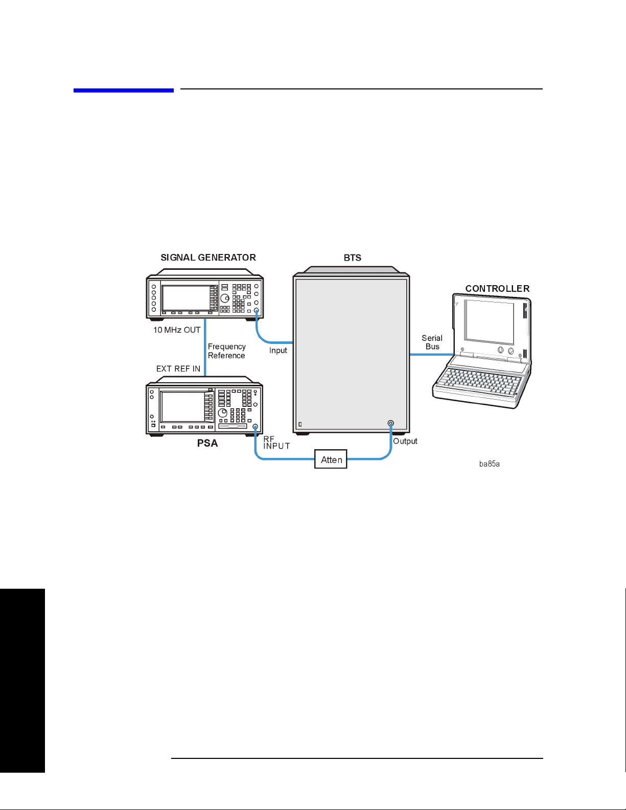
Making Measurements
Transmit Power Measurement
Transmit Power Measurement
One-Button BTS Measurement Procedure
Step 1. Configure the Device Under Test (DUT) as follows.
The base transmission station (BTS) under test has to be set to transmit the one RF carrier remotely
through the system controller. This transmitting signal is connected to the instruments RF input port.
Connect the equipment as shown.
Figure 2-1 Base Station Equipment Measurement System Setup
Making Measurements
a. Using the appropriate cables and adapters, connect the modulated signal, using the proper radio
standard, from the signal generator to the amplifier input connector of the BTS.
b. Connect the output signal of the BTS to the RF input port of the instrument, through the attenuator.
c. Connect a BNC cable between the 10 MHz OUT port of the signal generator and the EXT REF IN
port of the instrument.
d. Connect the system controller to the BTS through the serial bus cable.
Step 2. From the system controller, perform all of the call acquisition functions required
for the BTS to transmit the RF signal.
Step 3. Enable the TD-SCDMA measurement personality mode by pressing
TD-SCDMA. (The desired mode key may not be on the first page of the menu. If
not, press
More until the key is available.)
MODE,
Step 4. If you want to set the current measurement personality mode to a known, factory
default state, ensure that the preset type is set to Mode, press
38 Chapter 2
Preset.

Making Measurements
Transmit Power Measurement
NOTE To preset only the parameter settings that are specific to the selected measurement,
press
Meas Setup, Restore Meas Defaults. (The Restore Meas Defaults key may
not be on the first page of the menu. If not, press More until the key is available.)
Step 5. Toggle the device to
Step 6. Set the desired center frequency by pressing
Freq
, then use the numeric keypad to enter the frequency of interest.
Step 7. Select the measurement by pressing
BTS by pressing Mode Setup, Radio, Device.
FREQUENCY Channel, Center
MEASURE and the Transmit Power key.
(The desired measurement key may not be on the first page of the menu. If not,
More until the key is available.)
press
Depending on the current settings of
Meas Control, the instrument will begin making the selected
measurements. The resulting data will be shown on the display or available for export. For additional
information on the measurement results for your selection, refer to “Measurement Results” on page 39
Step 8. You may need to change some of the display settings. These changes should not
affect the measurement results, but will affect how you view the measurement
results on the instrument display.
The
AMPLITUDE Y Scale key accesses the menu to set the desired vertical scale and associated settings:
Scale/Div, Ref Level.
Step 9. If you want to change the measurement parameters from their default condition so
that you can make a customized measurement, press
Meas Setup to see the
available keys. For additional information on the use of the available keys and
customizing your measurement, refer to “Transmit Power ” on page 105. For
additional information on the measurement concepts, refer to “Transmit Power
Measurement Concepts” on page 249.
Measurement Results
Figure 2-2 shows an example of the Transmit Power measurement result with the measurement method
set to measured burst width. The transmit power graph is shown in the graph window. The measured
mean transmit power, current data minimum and maximum power points, full burst width, along with the
amplitude threshold level used are shown in the text window.
Chapter 2 39
Making Measurements
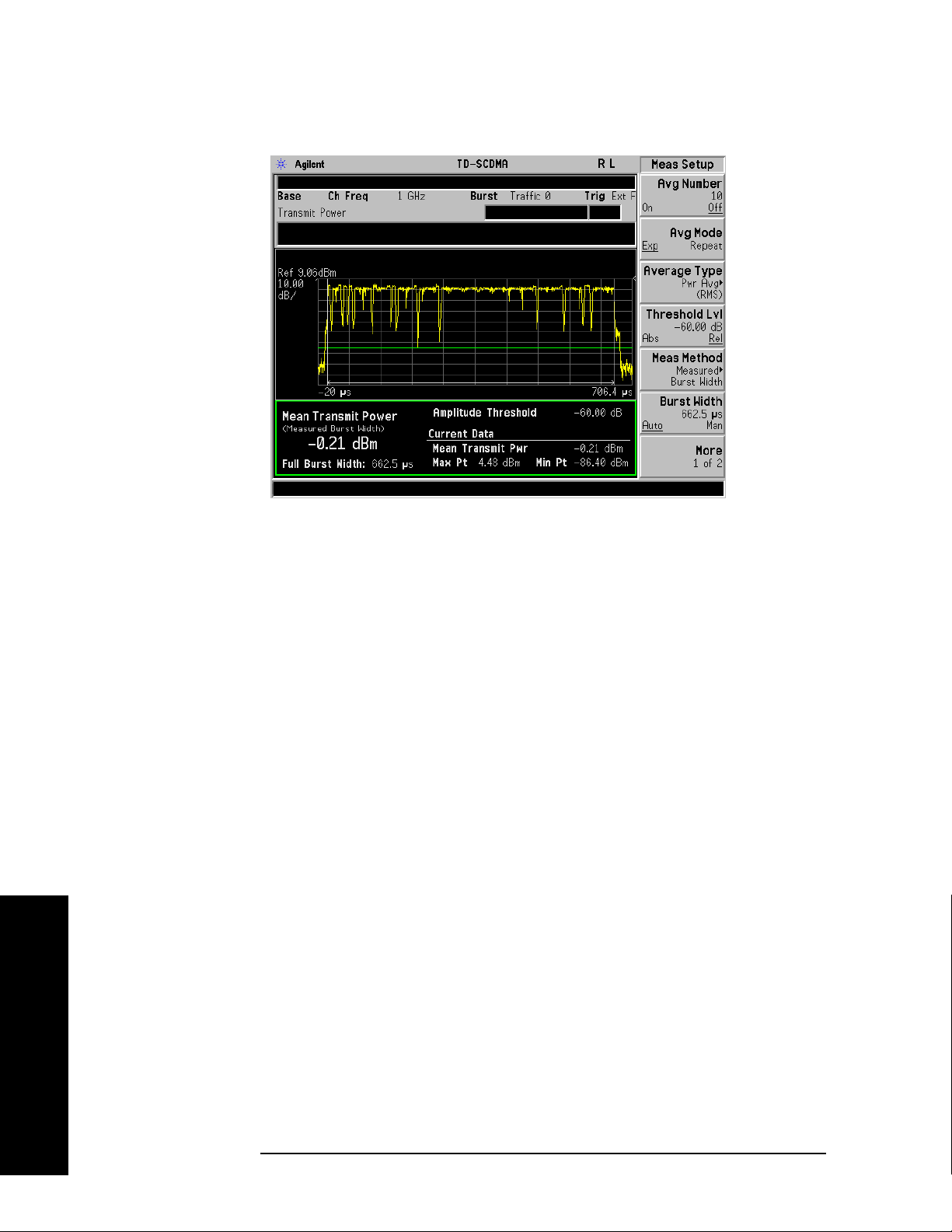
Making Measurements
Transmit Power Measurement
Figure 2-2 Transmit Power—Measured Burst Width
Figure 2-3 shows an example of the Transmit Power measurement result with the measurement method
set to above threshold level. The transmit power graph is shown in the graph window. The measured
mean transmit power, current data minimum and maximum power points, along with the amplitude
threshold level used are shown in the text window.
Figure 2-4 shows an example of the Transmit Power measurement result with the measurement method
set to single time slot. The transmit power graph is shown in the graph window. The measured mean
transmit power, current data minimum and maximum power points, along with the amplitude threshold
level used are shown in the text window.
• Mean Transmit Power - The mean transmit power result can be calculated using one of two
methods:
— When the Measure Method parameter is set to Above Threshold Level, all trace data points above
the Threshold Lvl parameter value are averaged according to the selected Average Type
parameter.
— When the Measure Method parameter is set to Measured Burst Width, the trace data points that
fall within the Burst Width are averaged according to the selected Average Type parameter. These
data points are indicated on the screen as the region between the two white vertical lines.
— When the Measure Method parameter is set to Signal Time Slot, the trace data points that fall with
the time slot specified in the Frequency Channel menu are indicated on the screen as the region
between the two green vertical lines.
Making Measurements
The result is averaged according to the Average Number, Average Mode, and Average Type
parameter settings.
• Max Pt. - The max pt is current data, and therefore is based on the current trace, and not the averaged
data. It gives the maximum trace point detected over the entire trace.
40 Chapter 2
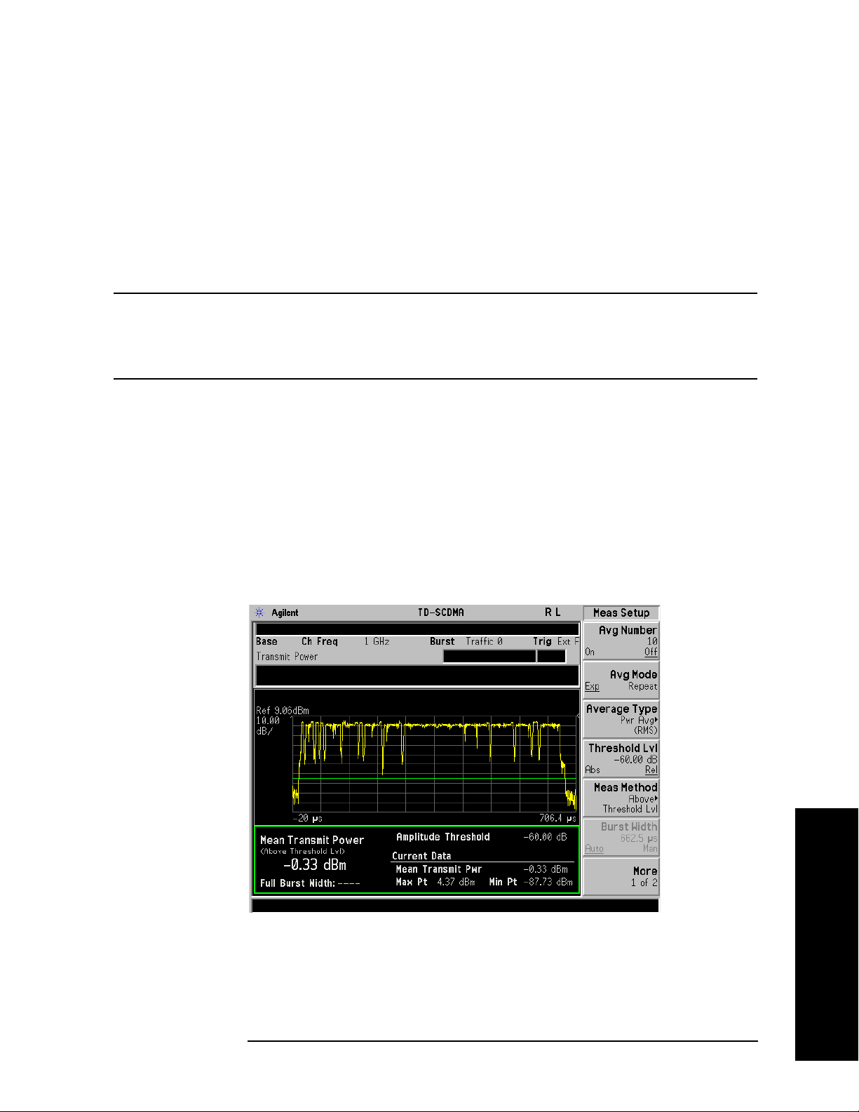
Making Measurements
Transmit Power Measurement
• Min Pt. - The min pt is current data, and therefore is based on the current trace, and not the averaged
data. It gives the minimum trace point detected over the entire trace.
• Full Burst Width - The full burst width result is the time between the detected –6 dB start and stop
points relative to the mean transmit power of the first detected “active” timeslot. This result metric is
only available when the Measure Method parameter is set to Measured Burst Width.
If no signal timeslots are determined to be “active”, all the screen results are unavailable (four dashed
lines are shown).
NOTE It may be necessary to adjust the Threshold Lvl parameter located under the Meas
Setup menu, to achieve reliable detection of the input signal active timeslots. Use
of an inappropriate value for the Threshold Lvl parameter may result in all the
screen results being unavailable (four dashed lines are shown).
• Amplitude Threshold - The relative or absolute value of the Threshold Lvl setup parameter is
displayed on the screen, and represents the level of the green horizontal amplitude threshold line
displayed in the graph window.
In the Above Threshold Level measurement method, the Amplitude Threshold determines the level
above which trace points will be included in the Mean Transmit Power result calculation.
In the Measured Burst Width measurement method, the Amplitude Threshold determines the burst
search threshold level to be used by the Transmit Power measurement in determining whether or not
a signal timeslot is active or not.
Figure 2-3 Transmit Power—Above Threshold Level
Making Measurements
Chapter 2 41

Making Measurements
Transmit Power Measurement
Figure 2-4 Transmit Power—Single Time Slot
Figure 2-5 Transmit Power—Meas Time = 1
Making Measurements
42 Chapter 2

Figure 2-6 Transmit Power—Meas Time = 9 Full Frame
Making Measurements
Transmit Power Measurement
If you have a problem and get an error message, refer to the “Instrument Messages and Functional Tests”
manual.
Troubleshooting Hints
Low output power can lead to poor coverage and intermittent service for phone users. Out of
specification power measurements indicate a fault usually in the power amplifier circuitry. They can also
provide early indication of a fault with the power supply, i.e. the battery in the case of mobile stations.
Making Measurements
Chapter 2 43

Making Measurements
Power Versus Time Measurement
Power Versus Time Measurement
One-Button BTS Measurement Procedure
Step 1. Configure the Device Under Test (DUT) as follows.
The base transmission station (BTS) under test has to be set to transmit the one RF carrier remotely
through the system controller. This transmitting signal is connected to the instruments RF input port.
Connect the equipment as shown.
Figure 2-7 Base Station Equipment Measurement System Setup
Making Measurements
a. Using the appropriate cables and adapters, connect the modulated signal, using the proper radio
standard, from the signal generator to the amplifier input connector of the BTS.
b. Connect the output signal of the BTS to the RF input port of the instrument, through the attenuator.
c. Connect a BNC cable between the 10 MHz OUT port of the signal generator and the EXT REF IN
port of the instrument.
d. Connect the system controller to the BTS through the serial bus cable.
Step 2. From the system controller, perform all of the call acquisition functions required
for the BTS to transmit the RF signal.
Step 3. Enable the TD-SCDMA measurement personality mode by pressing
TD-SCDMA. (The desired mode key may not be on the first page of the menu. If
not, press
More until the key is available.)
MODE,
Step 4. If you want to set the current measurement personality mode to a known, factory
default state, ensure that the preset type is set to Mode, press
44 Chapter 2
Preset.

Making Measurements
Power Versus Time Measurement
NOTE To preset only the parameter settings that are specific to the selected measurement,
press
Meas Setup, Restore Meas Defaults. (The Restore Meas Defaults key may
not be on the first page of the menu. If not, press More until the key is available.)
Step 5. Toggle the device to
Step 6. Set the desired center frequency by pressing
Freq
, then use the numeric keypad to enter the frequency of interest.
Step 7. Select the measurement by pressing
BTS by pressing Mode Setup, Radio, Device.
FREQUENCY Channel, Center
MEASURE and the Pwr vs Time key. (The
desired measurement key may not be on the first page of the menu. If not, press
More until the key is available.)
Depending on the current settings of
Meas Control, the instrument will begin making the selected
measurements. The resulting data will be shown on the display or available for export. For additional
information on the measurement results for your selection, refer to “Measurement Results” on page 46
Step 8. It may be necessary to adjust the external trigger Delay parameter located under
the Trigger menu, to achieve reliable detection of the input signal active timeslots.
Proper adjustment of the external trigger delay can be achieved by ensuring the rise and fall edges of the
input signal active timeslot align with the location of the two white vertical Burst Lines displayed in the
graph window. These Burst Lines represent the theoretical expected location of the selected Burst Type
and Traffic Slot parameters, when the external trigger event occurs at the start of each 5 msec frame.
Using an inappropriate value for the external trigger Delay parameter may result in both the Full Burst
Width result being made unavailable (four dashed lines are shown) as well as an inappropriate Power vs
Time limit mask being automatically created and applied resulting in a potential limit test FAIL.
Step 9. It may be necessary to adjust the Burst Search Threshold parameter located under
the Trigger menu, to achieve reliable detection of the input signal active timeslots.
Use of an inappropriate value of the Burst Search Threshold parameter may result in both the Full Burst
Width result being made unavailable (four dashed lines are shown) as well as an inappropriate Power vs
Time limit mask being automatically created and applied resulting in a potential limit test FAIL.
Step 10. You may need to change some of the display settings. These changes should not
affect the measurement results, but will affect how you view the measurement
results on the instrument display.
AMPLITUDE Y Scale key accesses the menu to set the desired vertical scale and associated settings:
The
Scale/Div and Ref Level.
Chapter 2 45
Making Measurements

Making Measurements
Power Versus Time Measurement
Step 11. If you want to change the measurement parameters from their default condition so
that you can make a customized measurement, press
Meas Setup to see the
available keys. Then, for additional information on the use of the available keys
and customizing your measurement, refer to “Power vs Time ” on page 120. For
additional information on the measurement concepts, refer to “Power Versus Time
Measurement Concepts” on page 252.
Measurement Results
The following figure shows an example of the results of Power vs Time measurement in the graph
window. The measured mean transmit power, transmit off power, current data minimum and maximum
power points, and full burst width are shown in the text window.
When the Auto RF Input Range parameter is set to On, the spectrum analyzer reference level and
attenuator are set automatically.
For averaged measurements, you may specify the number of sweeps over which to average the result.
Figure 2-8 Power vs Time Measurement
Making Measurements
Information shown in the data window of the displays include:
• Mean Transmit Power - The Mean Transmit Pwr result is measured over the transmission period of
the selected Burst Type, which is indicated on screen as the region between the two white vertical
lines displayed when the Burst Lines display parameter is enabled.
The result is averaged according to the Average Number, Average Mode, and Average Type
parameter settings.
46 Chapter 2

Making Measurements
Power Versus Time Measurement
• Transmit Off Power - The transmit off power result is measured in accordance with the TSM
specification. It is a measure the average power of the BTS or MS output signal over the transmit off
power period region starting 11 chips before the start of any “inactive” time slot, and ending 8 chips
before any following “active” time slot. Also, if there are more than one “inactive” region, then the
average power measurement is made over all “inactive” regions.
The result is averaged according to the Average Number, Average Mode, and Average Type
parameter settings.
If all signal timeslots are determined to be “active”, the screen result is unavailable (four dashed lines
are shown) and SCPI_ = 9.91E37 is returned for this result when the measurement results are queried
remotely.
• Max Pt. - The max pt is current data, and therefore is based on the current trace, and not the averaged
data. It gives the maximum trace point detected over the entire trace.
• Min Pt. - The min pt is current data, and therefore is based on the current trace, and not the averaged
data. It gives the minimum trace point detected over the entire trace.
• Full Burst Width - The full burst width result is the time between the detected –3 dB start and stop
points relative to the mean transmit power of the selected Burst Type timeslot.
If the selected Burst Type signal timeslot is determined to be “inactive”, the screen result is
unavailable (four dashed lines are shown) and SCPI_NAN = 9.91E37 is returned for this result when
the measurement results are queried remotely.
Figure 2-9 Power vs Time—Meas Time = 1
Making Measurements
Chapter 2 47
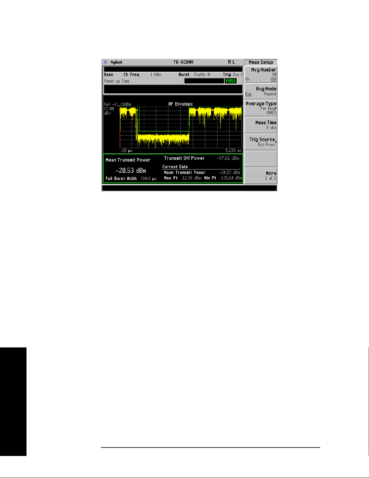
Making Measurements
Power Versus Time Measurement
Figure 2-10 Power vs Time—Meas Time = 9 Full Frame
If you have a problem and get an error message, refer to the “Instrument Messages and Functional Tests”
manual.
Troubleshooting Hints
If a transmitter fails the Power vs. Time measurement this usually indicates a problem with the units
output amplifier or leveling loop.
Making Measurements
48 Chapter 2

Making Measurements
ACP (ACLR) Measurement
ACP (ACLR) Measurement
One-Button MS Measurement Procedure
Step 1. Configure the Device Under Test (DUT) as follows.
The mobile station (MS) under test has to be set to transmit the RF power remotely through the system
controller. This transmitting signal is connected to the instruments RF input port. Connect the equipment
as shown.
Figure 2-11 Mobile Station Equipment Measurement System Setup
a. Using the appropriate cables, adapters, and circulator, connect the output signal from the MS to the
RF input port of the instrument.
b. Connect the base transmission station simulator or signal generator to the MS through the circulator
to initiate a link constructed with the sync and pilot channels, if required.
c. Connect a BNC cable between the 10 MHz OUT port of the signal generator and the EXT REF IN
port of the instrument.
d. Connect the system controller to the MS through the serial bus cable to control the MS operation.
Step 2. From the system controller, perform all of the call acquisition functions required
for the MS to transmit the RF signal.
Step 3. Enable the TD-SCDMA measurement personality mode by pressing
TD-SCDMA. (The desired mode key may not be on the first page of the menu. If
not, press
More until the key is available.)
MODE,
Step 4. If you want to set the current measurement personality mode to a known, factory
default state, ensure that the preset type is set to Mode, press
Chapter 2 49
Preset.
Making Measurements

Making Measurements
ACP (ACLR) Measurement
NOTE To preset only the parameter settings that are specific to the selected measurement,
press
Meas Setup, Restore Meas Defaults. (The Restore Meas Defaults key may
not be on the first page of the menu. If not, press More until the key is available.)
Step 5. Toggle the device to
Step 6. Set the desired center frequency by pressing
Freq
, then use the numeric keypad to enter the frequency of interest.
Step 7. Start your measurement by pressing
measurement key may not be on the first page of the menu. If not, press
MS by pressing Mode Setup, Radio, Device.
FREQUENCY Channel and Center
MEASURE and the ACP key. (The desired
More until
the key is available.)
Depending on the current settings of
Meas Control, the instrument will begin making the selected
measurements. The resulting data will be shown on the display or available for export. For additional
information on the measurement results for your selection, refer to “Measurement Results” on page 50
Step 8. You may need to change some of the display settings. These changes should not
affect the measurement results, but will affect how you view the measurement
results on the instrument display.
The
AMPLITUDE Y Scale key accesses the menu to set the desired vertical scale and associated settings:
Scale/Div and Ref Level.
Step 9. Depending on the mode and measurement you have selected, various graphical
and tabular presentations are available. To set the display presentation you need,
Trace/View and select the desired presentation from the menu list displayed.
press
Step 10. If you want to change the measurement parameters from their default condition so
that you can make a customized measurement, press
Meas Setup to see the
available keys. Then, for additional information on using the available keys and
customizing your measurement, refer to “Adjacent Channel Power Ratio (ACPR)”
on page 142. For additional information on the measurement concepts, refer to
“Adjacent Channel Power (ACP) Measurement Concepts” on page 254.
Making Measurements
Step 11. If you want to enable the gated LO sweep feature in this measurement press the
Sweep front-panel key to see the available gate setup keys. Then, for additional
information on the use of the available keys, refer to “Sweep Functions” on
page 80.
Measurement Results
Figure 2-12 shows an example result of ACP (Total Pwr Ref) measurement in the bar graph window
when you have selected the measurement mode indicated. The absolute and relative power levels on
both sides of the carrier frequency are displayed in the graphic window and text window. The text
window shows the absolute total power reference, while the lower and upper offset channel power levels
are displayed in both absolute and relative readings.
50 Chapter 2

Figure 2-12 ACP Measurement - Bar Graph View
Making Measurements
ACP (ACLR) Measurement
NOTE For ACP measurements with DwPTS, since DwPTS is very short (75 us) in length,
to make an accurate measurement, longer measurement time is needed and the
numeric result display will be refreshed after the trace is completed.
You can press the
View/Trace, Spectrum keys to see the ACP Spectrum graph with the bandwidth
marker lines (which can be set in the Offset/Limits menu) in the graph window. The corresponding
measured data is also shown in the text window. (See Figure 2-13.)
Figure 2-13 ACP Measurement - Spectrum View
Making Measurements
Chapter 2 51
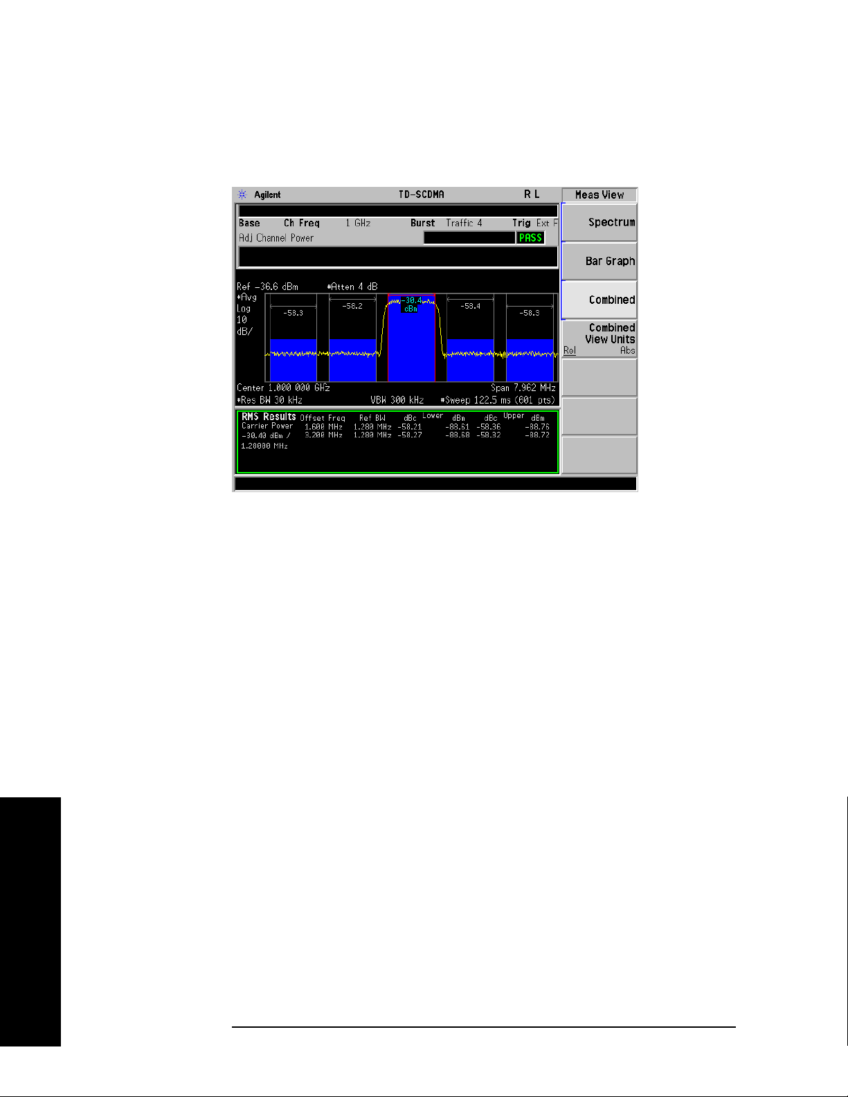
Making Measurements
ACP (ACLR) Measurement
You can press the View/Trace, Combined keys to see the ACP Bar graph combined with the Spectrum
graph. The corresponding measured data is also shown in the text window. (See Figure 2-14.)
Figure 2-14 ACP Measurement - Combined View
You can press the
View/Trace, Combined View Units keys to set the units used, for the data displayed in
the graphic window, to relative or absolute values.
If you have a problem and get an error message, refer to the “Instrument Messages and Functional Tests”
manual.
Troubleshooting Hints
This adjacent channel power ratio measurement can reveal degraded or defective parts in the transmitter
section of the DUT. The following examples are those areas to be checked further.
• Some faults in the DC power supply control of the transmitter power amplifier, RF power controller
of the pre-power amplifier stage, or I/Q control of the baseband stage
• Some degradation in the gain and output power level of the amplifier due to the degraded gain control
and/or increased distortion
• Some degradation of the amplifier linearity and other performance characteristics
Power amplifiers are one of the final stage elements of a base or mobile transmitter and are a critical part
of meeting the important power and spectral efficiency specifications. Since ACP measures the spectral
response of the amplifier to a complex wideband signal, it is a key measurement linking amplifier
linearity and other performance characteristics to the stringent system specifications.
Making Measurements
52 Chapter 2

Making Measurements
Multi-Carrier Power Measurement
Multi-Carrier Power Measurement
One-Button BTS Measurement Procedure
Step 1. Configure the Device Under Test (DUT) as follows.
The base transmission station (BTS) under test has to be set to transmit the one RF carrier remotely
through the system controller. This transmitting signal is connected to the instruments RF input port.
Connect the equipment as shown.
Figure 2-15 Base Station Equipment Measurement System Setup
a. Using the appropriate cables and adapters, connect the modulated signal, using the proper radio
standard, from the signal generator to the amplifier input connector of the BTS.
b. Connect the output signal of the BTS to the RF input port of the instrument, through the attenuator.
c. Connect a BNC cable between the 10 MHz OUT port of the signal generator and the EXT REF IN
port of the instrument.
d. Connect the system controller to the BTS through the serial bus cable.
Step 2. From the system controller, perform all of the call acquisition functions required
for the BTS to transmit the RF signal.
Step 3. Enable the TD-SCDMA measurement personality mode by pressing
TD-SCDMA. (The desired mode key may not be on the first page of the menu. If
not, press
More until the key is available.)
MODE,
Step 4. If you want to set the current measurement personality mode to a known, factory
default state, ensure that the preset type is set to Mode, press
Chapter 2 53
Preset.
Making Measurements

Making Measurements
Multi-Carrier Power Measurement
NOTE To preset only the parameter settings that are specific to the selected measurement,
press
Meas Setup and Restore Meas Defaults. (The Restore Meas Defaults key
may not be on the first page of the menu. If not, press
More until the key is
available.)
Step 5. Toggle the device to
Step 6. Set the desired center frequency by pressing
Freq
, then use the numeric keypad to enter the frequency of interest.
Step 7. Select the measurement by pressing
BTS by pressing Mode Setup, Radio, Device.
FREQUENCY Channel, Center
MEASURE and the Multi Carrier Power key.
(The desired measurement key may not be on the first page of the menu. If not,
press
More until the key is available.)
Depending on the current settings of
Meas Control, the instrument will begin making the selected
measurements. The resulting data will be shown on the display or available for export. For additional
information on the measurement results for your selection, refer to “Measurement Results” on page 54
Step 8. You may need to change some of the display settings. These changes should not
affect the measurement results, but will affect how you view the measurement
results on the instrument display.
AMPLITUDE Y Scale key accesses the menu to set the desired vertical scale and associated settings:
The
Scale/Div and Ref Level.
Step 9. If you want to change the measurement parameters from their default condition so
that you can make a customized measurement, press
Meas Setup to see the
available keys. Then, for additional information on using the available keys and
customizing your measurement, refer to “Multi-Carrier Power (MCP)” on
page 161. For additional information on the measurement concepts, refer to
“Multi-carrier Power Measurement Concepts” on page 255.
Making Measurements
Step 10. If you want to enable the gated LO sweep feature in this measurement press the
Sweep front-panel key to see the available gate setup keys. Then, for additional
information on the use of the available keys, refer to “Sweep Functions” on
page 80.
Measurement Results
Figure 2-16 shows an example result of the Spectrum View for the multi-carrier power measurement
with the bandwidth marker lines in the graph window. The relative and absolute power levels for the
center and second carriers, the lower and upper offset channels, and other parameters are shown in the
text window.
The example shows a 12 Carrier TD-SCDMA signal with the Carrier 1 Frequency at 991.2 MHz
(1000-0.8-5 x 1.6 = 991.2 MHz) set with 0 dBm power and Carrier 12 Frequency at 1008.8 MHz (1000
+ 0.8 + 5 x 1.6 = 1008.8 MHz) set with 10 dBm power. The remaining carriers, Carrier 2 to Carrier 11
are shown with no power.
54 Chapter 2
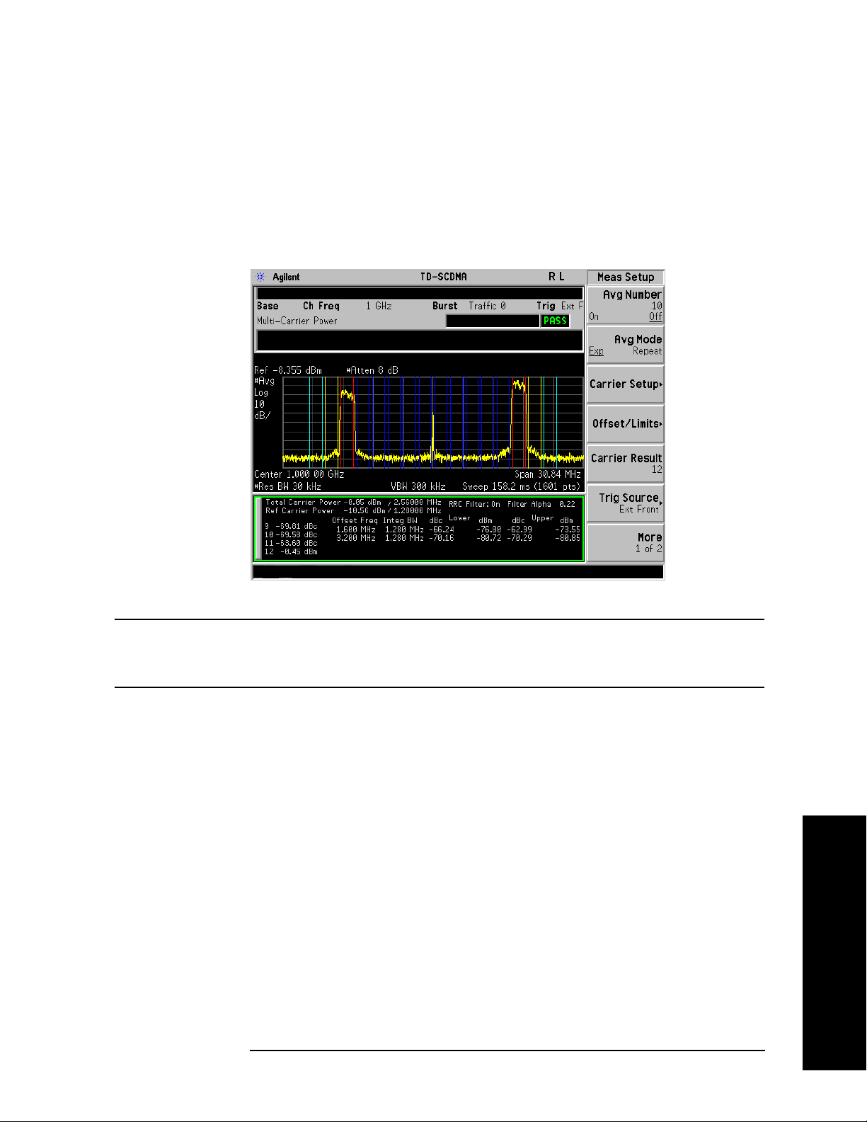
Multi-Carrier Power Measurement
The colored vertical bars on the spectrum view indicate the following:
— Dark Blue lines: represent the carriers with no power (Carriers from 2 to 11)
— Red lines: represent the carriers with power
— Yellow lines: represent the Upper & Lower 1.6 MHz offset
— Light Blue lines: represent the Upper & Lower 3.2 MHz offset
Figure 2-16 MCP Measurement - Spectrum View
Making Measurements
NOTE For the MCP measurement with DwPTS, since DwPTS is very short (75 us) in
length, to make an accurate measurement, longer measurement time is needed and
the numeric result display will be refreshed after the trace is completed.
You can press the
View/Trace, Combined keys to see the MCP Bar graph combined with the Spectrum
graph. The corresponding measured data is also shown in the text window. (See Figure 2-17.)
Making Measurements
Chapter 2 55
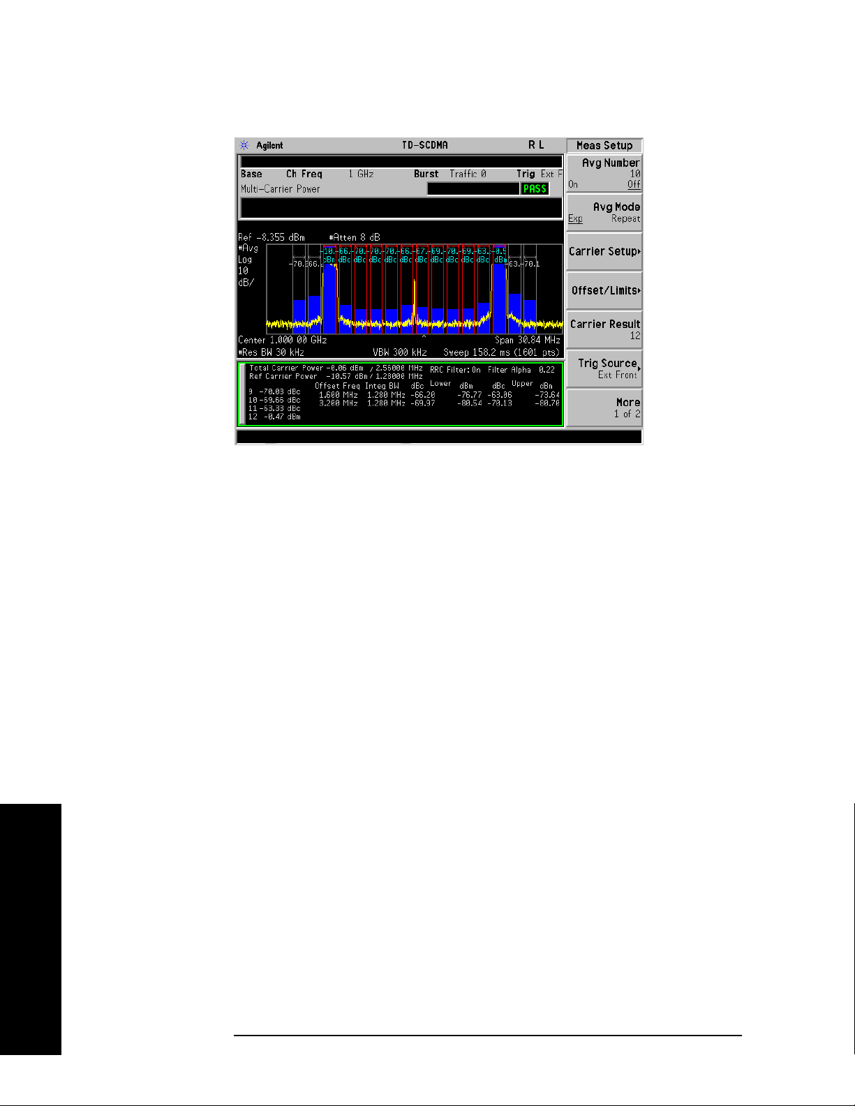
Making Measurements
Multi-Carrier Power Measurement
Figure 2-17 MCP Measurement - Combined View
You can press the
View/Trace, Combined View Units keys to set the units used, for the data displayed in
the graphic window, to relative or absolute values.
Troubleshooting Hints
If there is a frequency channel dependency in the operating characteristics of a multi-carrier power
amplifier, it might have channel balance problems due to spurious response, distortion, and/or
intermodulation products.
If you have a problem and get an error message, refer to the “Instrument Messages and Functional Tests”
manual.
Making Measurements
56 Chapter 2
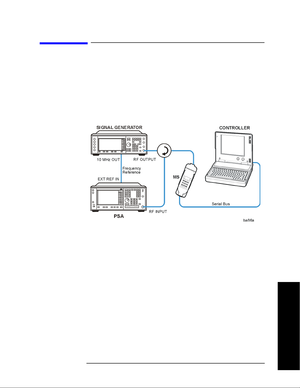
Making Measurements
Spurious Emissions Measurement
Spurious Emissions Measurement
One-Button MS Measurement Procedure
Step 1. Configure the Device Under Test (DUT) as follows.
The mobile station (MS) under test has to be set to transmit the RF power remotely through the system
controller. This transmitting signal is connected to the instruments RF input port. Connect the equipment
as shown.
Figure 2-18 Mobile Station Equipment Measurement System Setup
a. Using the appropriate cables, adapters, and circulator, connect the output signal from the MS to the
RF input port of the instrument.
b. Connect the base transmission station simulator or signal generator to the MS through the circulator
to initiate a link constructed with the sync and pilot channels, if required.
c. Connect a BNC cable between the 10 MHz OUT port of the signal generator and the EXT REF IN
port of the instrument.
d. Connect the system controller to the MS through the serial bus cable to control the MS operation.
Step 2. From the system controller, perform all of the call acquisition functions required
for the MS to transmit the RF power as required.
Step 3. Enable the TD-SCDMA measurement personality mode by pressing
TD-SCDMA. (The desired mode key may not be on the first page of the menu. If
not, press
More until the key is available.)
MODE,
Step 4. If you want to set the current measurement personality mode to a known, factory
default state, ensure that the preset type is set to Mode, press
Chapter 2 57
Preset.
Making Measurements

Making Measurements
Spurious Emissions Measurement
NOTE To preset only the parameter settings that are specific to the selected measurement,
press
Meas Setup and Restore Meas Defaults. (The Restore Meas Defaults key
may not be on the first page of the menu. If not, press
More until the key is
available.)
Step 5. Toggle the device to
Step 6. Set the desired center frequency by pressing
Freq
, then use the numeric keypad to enter the frequency of interest.
Step 7. Start your measurement by pressing
MS by pressing Mode Setup, Radio, Device.
FREQUENCY Channel, Center
MEASURE and the Spurious Emissions key.
(The desired measurement key may not be on the first page of the menu. If not,
press
More until the key is available.)
Depending on the current settings of
Meas Control, the instrument will begin making the selected
measurements. The resulting data will be shown on the display or available for export. For additional
information on the measurement results for your selection, refer to “Measurement Results” on page 59
Step 8. You may need to change some of the display settings. These changes should not
affect the measurement results, but will affect how you view the measurement
results on the instrument display.
AMPLITUDE Y Scale key accesses the menu to set the desired vertical scale and associated settings:
The
Scale/Div and Ref Level.
Step 9. Depending on the mode and measurement you have selected, various graphical
and tabular presentations are available. To set the display presentation you need,
Trace/View and select the desired presentation from the menu list displayed.
press
Step 10. If you want to change the measurement parameters from their default condition so
that you can make a customized measurement, press
Meas Setup to see the
available keys. Then, for additional information on using the available keys and
customizing your measurement, refer to “Spurious Emissions” on page 184. For
additional information on the measurement concepts, refer to “Spurious Emissions
Measurement Concepts” on page 259.
Making Measurements
58 Chapter 2

Making Measurements
Spurious Emissions Measurement
Measurement Results
The Spurious Emissions measurement results should look like the next figure. The spectrum window and
the text window show the Spurs that are within the current value of the Marker Peak Excursion setting of
the absolute limit. Any spur that has failed the absolute limit will have the red ‘F’ beside it.
Figure 2-19 Spurious Emissions Measurement
If you have a problem and get an error message, refer to the “Instrument Messages and Functional Tests”
manual.
Troubleshooting Hints
If there is a frequency channel dependency in the operating characteristics of a multi-carrier power
amplifier, it might have channel balance problems due to spurious response, distortion, and/or
intermodulation products.
Making Measurements
Chapter 2 59

Making Measurements
Spectrum Emission Mask (SEM) Measurement
Spectrum Emission Mask (SEM) Measurement
One-Button MS Measurement Procedure
Step 1. Configure the Device Under Test (DUT) as follows.
The mobile station (MS) under test has to be set to transmit the RF power remotely through the system
controller. This transmitting signal is connected to the instruments RF input port. Connect the equipment
as shown.
Figure 2-20 Mobile Station Equipment Measurement System Setup
Making Measurements
a. Using the appropriate cables, adapters, and circulator, connect the output signal from the MS to the
RF input port of the instrument.
b. Connect the base transmission station simulator or signal generator to the MS through the circulator
to initiate a link constructed with the sync and pilot channels, if required.
c. Connect a BNC cable between the 10 MHz OUT port of the signal generator and the EXT REF IN
port of the instrument.
d. Connect the system controller to the MS through the serial bus cable to control the MS operation.
Step 2. From the system controller, perform all of the call acquisition functions required
for the MS to transmit the RF power as required.
Step 3. Enable the TD-SCDMA measurement personality mode by pressing
TD-SCDMA. (The desired mode key may not be on the first page of the menu. If
not, press
More until the key is available.)
MODE,
Step 4. If you want to set the current measurement personality mode to a known, factory
default state, ensure that the preset type is set to Mode, press
60 Chapter 2
Preset.

Making Measurements
Spectrum Emission Mask (SEM) Measurement
NOTE To preset only the parameter settings that are specific to the selected measurement,
press
Meas Setup and Restore Meas Defaults. (The Restore Meas Defaults key
may not be on the first page of the menu. If not, press
More until the key is
available.)
Step 5. Toggle the device to
Step 6. Set the desired center frequency by pressing
Freq
, then use the numeric keypad to enter the frequency of interest.
Step 7. Start your measurement by pressing
Spectrum Emission Mask key. (The desired measurement key may not be on the
first page of the menu. If not, press
Depending on the current settings of
MS by pressing Mode Setup, Radio, Device.
FREQUENCY Channel, Center
MEASURE and the
More until the key is available.)
Meas Control, the instrument will begin making the selected
measurements. The resulting data will be shown on the display or available for export. For additional
information on the measurement results for your selection, refer to “Measurement Results” on page 61
Step 8. You may need to change some of the display settings. These changes should not
affect the measurement results, but will affect how you view the measurement
results on the instrument display.
AMPLITUDE Y Scale key accesses the menu to set the desired vertical scale and associated settings:
The
Scale/Div and Ref Level.
Step 9. Depending on the mode and measurement you have selected, various graphical
and tabular presentations are available. To set the display presentation you need,
Trace/View and select the desired presentation from the menu list displayed.
press
Step 10. If you want to change the measurement parameters from their default condition so
that you can make a customized measurement, press
Meas Setup to see the
available keys. Then, for additional information on using the available keys and
customizing your measurement, refer to “Spectrum Emissions Mask” on page 207.
For additional information on the measurement concepts, refer to “Spectrum
Emissions Mask (SEM) Measurement Concepts” on page 258.
Step 11. If you want to enable the gated LO sweep feature in this measurement press the
Sweep front-panel key to see the available gate setup keys. Then, for additional
information on the use of the available keys, refer to “Sweep Functions” on
page 80.
Measurement Results
The following figures show examples of Integrated Power View, Rel Peak Pwr & Freq View, and Abs
Peak Pwr & Freq View result metrics.
The relative and absolute integrated power levels for each offset frequency range on both sides of the
reference channel are displayed in the Integrated Power View.
Chapter 2 61
Making Measurements

Making Measurements
Spectrum Emission Mask (SEM) Measurement
The relative peak power levels along with the frequency of the peak in each offset frequency range on
both sides of the reference channel are displayed in the Rel Peak Pwr & Freq View.
The absolute peak power levels along with the frequency of the peak in each offset frequency range on
both sides of the reference channel are displayed in the Abs Peak Pwr & Freq View.
Figure 2-21 SEM Measurement—Integrated Power View
Making Measurements
Figure 2-22 Standard Results Screen—Rel Peak Pwr & Freq View
62 Chapter 2

Spectrum Emission Mask (SEM) Measurement
Figure 2-23 Standard Results Screen—Abs Peak Pwr & Freq View
Making Measurements
If you have a problem and get an error message, refer to the “Instrument Messages and Functional Tests”
manual.
Troubleshooting Hints
This spectrum emission mask measurement can reveal degraded or defective parts in the transmitter
section of the DUT. The following examples are those areas to be checked further.
• Faulty DC power supply control of the transmitter power amplifier.
• RF power controller of the pre-power amplifier stage.
• I/Q control of the baseband stage.
• Some degradation in the gain and output power level of the amplifier due to the degraded gain control
and/or increased distortion.
• Some degradation of the amplifier linearity or other performance characteristics.
Power amplifiers are one of the final stage elements of a base or mobile transmitter and are a critical part
of meeting the important power and spectral efficiency specifications. Since spectrum emission mask
measures the spectral response of the amplifier to a complex wideband signal, it is a key measurement
linking amplifier linearity and other performance characteristics to the stringent system specifications.
Making Measurements
Chapter 2 63
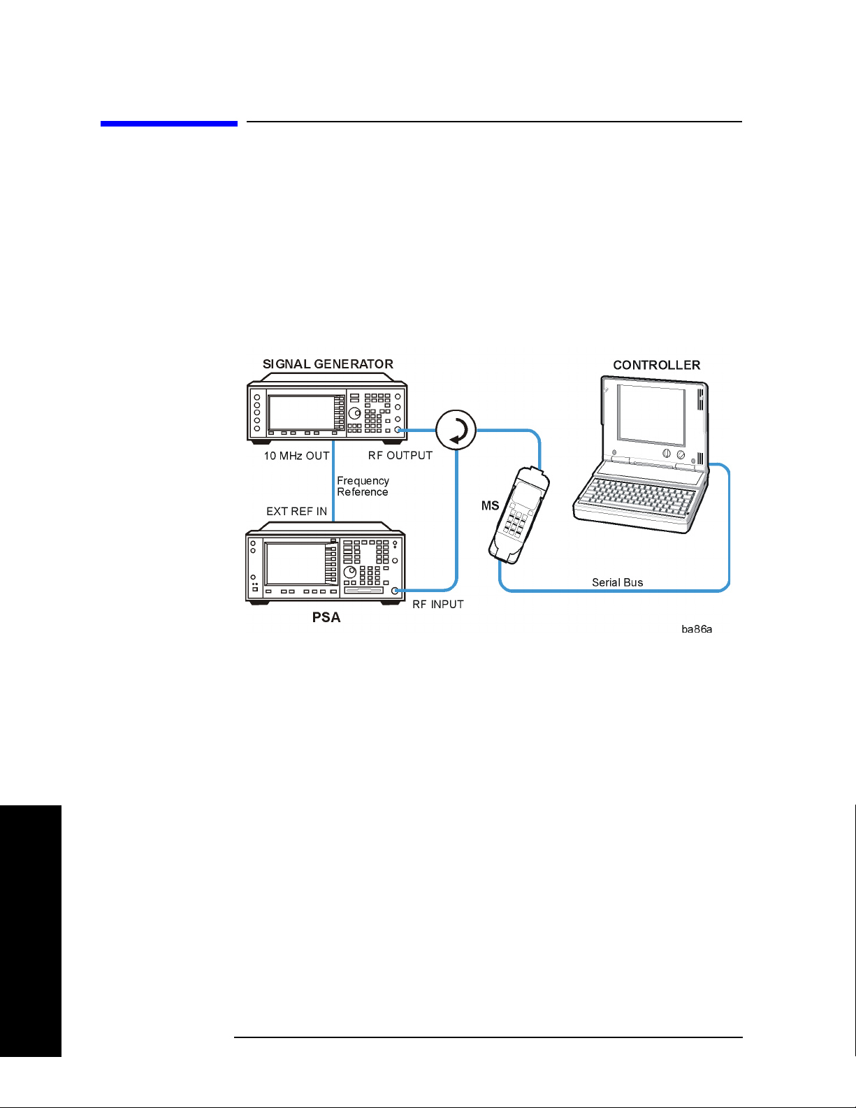
Making Measurements
Occupied Bandwidth Measurement
Occupied Bandwidth Measurement
One-Button MS Measurement Procedure
Step 1. Configure the Device Under Test (DUT) as follows.
The mobile station (MS) under test has to be set to transmit the RF power remotely through the system
controller. This transmitting signal is connected to the instruments RF input port. Connect the equipment
as shown.
Figure 2-24 Mobile Station Equipment Measurement System Setup
Making Measurements
a. Using the appropriate cables, adapters, and circulator, connect the output signal from the MS to the
RF input port of the instrument.
b. Connect the base transmission station simulator or signal generator to the MS through the circulator
to initiate a link constructed with the sync and pilot channels, if required.
c. Connect a BNC cable between the 10 MHz OUT port of the signal generator and the EXT REF IN
port of the instrument.
d. Connect the system controller to the MS through the serial bus cable to control the MS operation.
Step 2. From the system controller, perform all of the call acquisition functions required
for the MS to transmit the RF power as required.
Step 3. Enable the TD-SCDMA measurement personality mode by pressing
TD-SCDMA. (The desired mode key may not be on the first page of the menu. If
not, press
More until the key is available.)
MODE,
Step 4. If you want to set the current measurement personality mode to a known, factory
default state, ensure that the preset type is set to Mode, press
64 Chapter 2
Preset.

Making Measurements
Occupied Bandwidth Measurement
Step 5. Toggle the device to MS by pressing Mode Setup, Radio, Device.
Step 6. Set the desired center frequency by pressing
Freq
, then use the numeric keypad to enter the frequency of interest.
Step 7. Start your measurement by pressing
MEASURE and the Occupied BW key. (The
FREQUENCY Channel, Center
desired measurement key may not be on the first page of the menu. If not, press
More until the key is available.)
Depending on the current settings of
Meas Control, the instrument will begin making the selected
measurements. The resulting data will be shown on the display or available for export. For additional
information on the measurement results for your selection, refer to “Measurement Results” on page 61
Step 8. You may need to change some of the display settings. These changes should not
affect the measurement results, but will affect how you view the measurement
results on the instrument display.
AMPLITUDE Y Scale key accesses the menu to set the desired vertical scale and associated settings:
The
Scale/Div and Ref Level.
Step 9. If you want to change the measurement parameters from their default condition so
that you can make a customized measurement, press
Meas Setup to see the
available keys. Then, for additional information on using the available keys and
customizing your measurement, refer to “Occupied Bandwidth (OBW)” on
page 235. For additional information on the measurement concepts, refer to
“Occupied Bandwidth (OBW) Measurement Concepts” on page 261.
Step 10. If you want to enable the gated LO sweep feature in this measurement press the
Sweep front-panel key to see the available gate setup keys. Then, for additional
information on the use of the available keys, refer to “Sweep Functions” on
page 80.
Making Measurements
Chapter 2 65
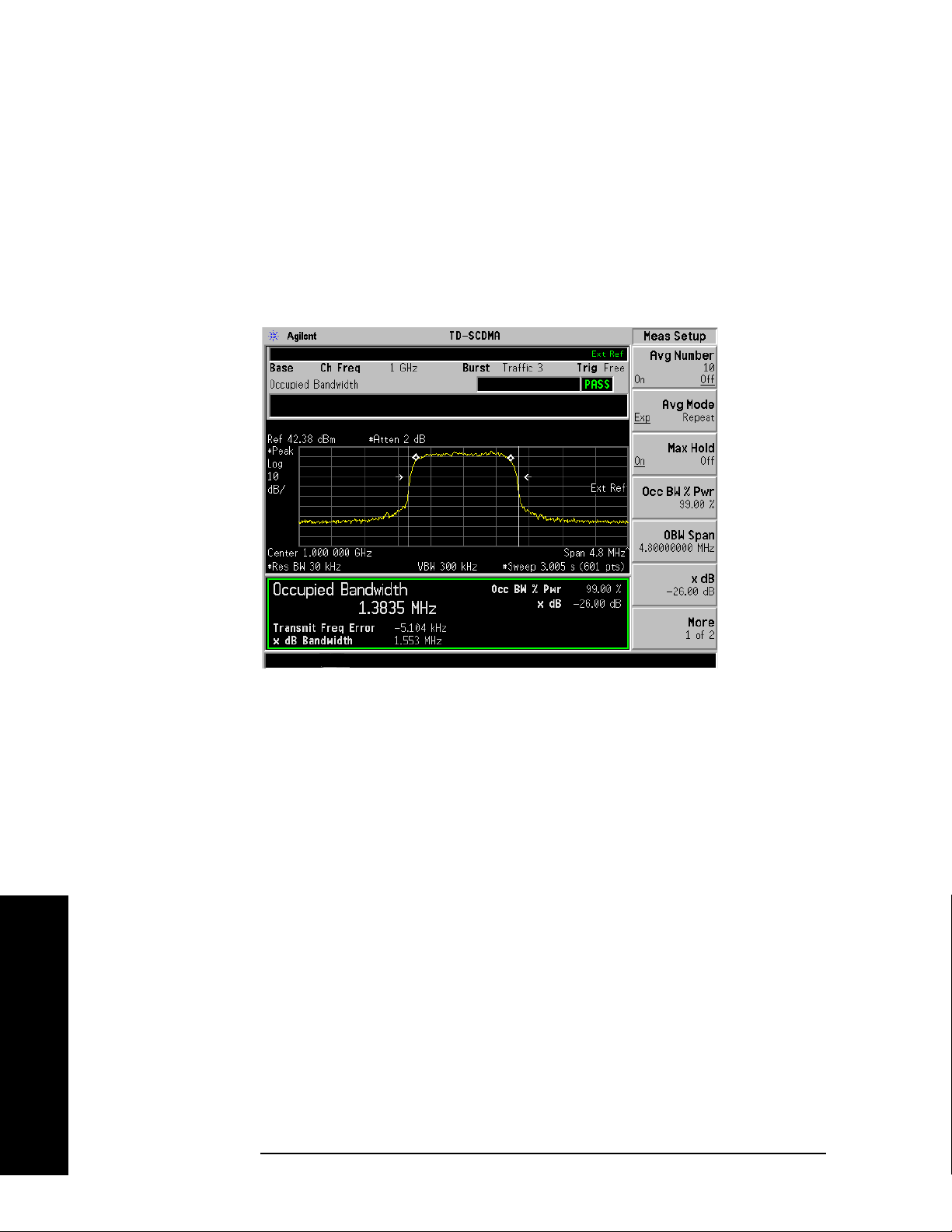
Making Measurements
Occupied Bandwidth Measurement
Measurement Results
The occupied bandwidth results are shown in Figure 2-25.
The different marks on the spectrum view indicate the following:
— A pair of white vertical lines: represent the 3GPP standard carrier bandwidth 1.6 MHz
— A pair of arrowheads: represent x dB bandwidth
— A pair of diamonds: represent the occupied bandwidth
Figure 2-25 Occupied Bandwidth Measurement Results
Making Measurements
Information shown in the text window of the displays include:
• Occupied Bandwidth - The result indicates the bandwidth containing 99% of the total transmitted
power.
The power of the transmitted signal is measured with a 30 kHz bandwidth approximate Gaussian
filter and a measurement span of 4.8 MHz, which is centered on the channel center frequency and
compliant with the 3GPP standard.
• Occ BW % Pwr - Specifies the percentage of the total power. The bandwidth which contains the
specified power will be measured. The default setting is 99%. You can adjust the parameter for your
testing.
• x dB - Defines the dB number relative to the peak level. The default setting is -26 dB. You can adjust
the parameter for your testing.
• Transmi t F req Error. - The result is the transmit frequency error from the specified center
frequency.
• x dB Bandwidth - The result is the frequency bandwidth when the power drops to the specified x dB
relative to the peak level, which is centered on channel center frequency.
If you have a problem and get an error message, refer to the “Instrument Messages and Functional Tests”
manual.
66 Chapter 2

Making Measurements
Occupied Bandwidth Measurement
Troubleshooting Hints
Any distortion such as harmonics or intermodulation, for example, produces undesirable power outside
the specified bandwidth.
Shoulders on either side of the spectrum shape indicate spectral regrowth and intermodulation. Rounding
or sloping of the top shape can indicate filter shape problems.
Chapter 2 67
Making Measurements

Making Measurements
Using Basic Mode
Using Basic Mode
Basic mode is part of Option B7J for the PSA Series Spectrum Analyzers. Basic mode is not related to a
particular communications standard. That is, it does not default to measurement settings that are for any
specific standard. You may want to use Basic Mode if you are making measurements on a signal that is
not based on a specific digital communications standard.
Basic Mode in PSA Series Spectrum Analyzers
There are two generic measurements available under the MEASURE key in Basic mode:
• Spectrum measurement (frequency domain).
• Waveform measurement (time domain)
See the PSA Series Basic Mode Guide for additional information.
Making Measurements
68 Chapter 2

Key and SCPI Reference
3 Key and SCPI Reference
69
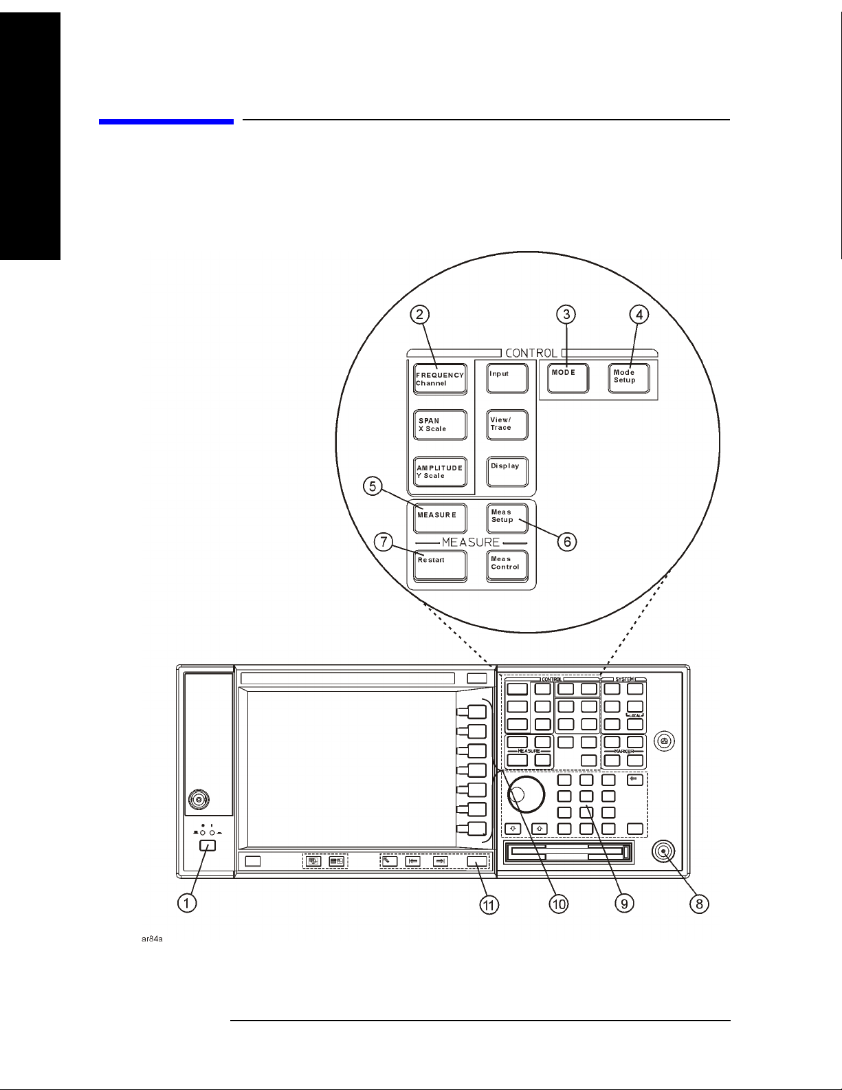
Key and SCPI Reference
Key and SCPI Reference
Instrument Front Panel Highlights
Instrument Front Panel Highlights
The most commonly used function keys on the PSA front panel are located as shown in the illustration
below. The operation of the keys is briefly explained on the following page.
Figure 3-1 Front Panel Major Key Locations - PSA Series
70 Chapter 3

Key and SCPI Reference
Instrument Front Panel Highlights
1. The On/Off switch toggles the power between on and off. A green LED will be on once the
instrument has been turned on. When in the standby mode a yellow LED is on above the On/Off
switch.
FREQUENCY Channel accesses the menu key that controls the center frequency or channel number.
2.
These parameters apply to all measurements in the current mode.
MODE accesses the menu key menu to select one of the radio systems measurement modes loaded in
3.
the instrument. Each mode is independent from all other modes.
Mode Setup accesses menu keys that affect parameters that are specific to the current mode and
4.
affect all measurements within that mode.
MEASURE accesses the menus to initiate one of the various measurements that are specific to the
5.
current mode.
Meas Setup accesses the menus of test parameters that are specific to the current measurement.
6.
Restart causes the measurement, for which the process is currently halted, to start again from the
7.
beginning of the measurement according to the current measurement setup parameters.
8. The RF INPUT port allows you to apply an external RF signal.
Key and SCPI Reference
9. The Data Entry keypad is used to enter numeric values for parameters. A value from this entry will
be displayed in the active function area of the screen. The value will become valid after pressing the
Enter key, or selecting a unit of measurement, depending on the current parameter.
10. The menu keys allow you either to activate a feature or to access a further menu key menu. An arrow
on the right side of a menu key label indicates that the key has a further selection menu. The active
menu key is highlighted. Grayed-out keys are currently unavailable for use or are only to show
information. If a menu key menu has multiple pages, access them by pressing the
More key at the
bottom of a menu.
11.
Return allows you to exit from the current menu and display the previous menu. If you are on the
first page of a multiple-page menu (the menu with
More (1 of 3) for example), the Return key will
exit from that menu. When you activate a different measurement, the return list is cleared. The
Return key will not return you to a previously activated mode, nor will it alter any values you have
entered on previous menus.
Chapter 3 71

Key and SCPI Reference
Common Functionality
Common Functionality
Key and SCPI Reference
Mode Switching
The TD-SCDMA mode is notified when a mode switch is about to happen. Upon leaving the
TD-SCDMA mode (as when another mode has been selected by the user), the TD-SCDMA mode is
saved into an ISTATE file in the flash file system. Mode ISTATE will consist of all measurement setup
settings, the current measurement, and the mode setup settings. Upon re-entry to the TD-SCDMA mode,
the mode state will be recalled from the stored ISTATE file. The mode will start with the same
measurement that was selected when exited and all measurement and mode settings will be restored.
Trace data and measurement results from the last time the mode was active are not restored.
Mode Selection on Power On/Preset
The mode that becomes active when the analyzer is turned on depends on the settings in the ‘Power
On/Preset’ menu under the ‘System’ front-panel key of the analyzer:
Value of Power On/Preset Parameter Mode entered at Power On
Power-On Last State Mode that was active at Power-down
Power-On Factory Preset Spectrum Analyzer Mode
TD-SCDMA Mode Entry
Upon entering the TD-SCDMA Mode, the last saved state for the TD-SCDMA Mode is restored. The
first time the mode is entered there will be no saved state information, and therefore the DLP will restore
the factory-preset state. The default measurement for the TD-SCDMA mode is Transmit Power. The first
time the TD-SCDMA personality is activated, this will be the active measurement. It will also be the
active measurement if TD-SCDMA is the active mode and a mode or factory preset (green Preset
front-panel key or remote :*RST) is performed.
TD-SCDMA Mode Exit
When the TD-SCDMA Mode exits, the state is saved, for the purposes of restoring the state the next time
the mode becomes active.
Mode Menu
When the TD-SCDMA personality has been installed and licensed on the spectrum analyzer, it will
appear in the menu brought up by the MODE front-panel key. Other modes might also be present on this
menu.
72 Chapter 3

Key and SCPI Reference
Common Functionality
Remote Control
Mode Selection by Mode Name
Selects the analyzer mode.
Mode TDSCDMA
Remote Command :INSTrument[:SELect] SA|TDSCDMA
:INSTrument[:SELect]?
Example :INSTrument:SELect TDSCDMA
Restriction and Notes Other modes may be available, depending on the software configuration of
the analyzer.
Preset SA
State Saved Saved in instrument state.
Range SA | TDSCDMA
Key and SCPI Reference
Key Path
Mode
Mode Selection by Mode Number
Selects the analyzer mode.
Mode TDSCDMA
Remote Command :INSTrument:NSELect 1|211
:INSTrument:NSELect?
Example :INSTrument:NSELect 211
Restriction and Notes Mode 1 is Spectrum Analysis. Mode 211 is the TD-SCDMA mode. Other
values may be accepted if other modes are loaded into the analyzer.
Preset 1
State Saved Saved in instrument state.
Range 1 | 211
Key Path
MODE
Chapter 3 73

Key and SCPI Reference
Common Functionality
Mode Setup Menu
Radio Menu
Key and SCPI Reference
Device
Sets the type of device (mobile or base station) to be tested.
Mode TDSCDMA
Remote Command [:SENSe]:RADio:DEVice BTS|MS
[:SENSe]:RADio:DEVice?
Example :SENSe:RADio:DEVice MS
Restriction and Notes Allows you to indicate if measurements will be performed to mobile (MS) or
base station (BTS) specifications. Changing this parameter will cause and
change to some parameters (measurement frequencies, bandwidths, and
limits) in some measurements.
Dependencies/Couplings When Device changes in TxP, PvT, ACP, MCP, SEM or OBW measurement,
Trigger Source and some other parameters will perform an auto couple. For
more information, refer to the Trigger Source table in each measurement
described in later chapters.
Preset BTS
State Saved Saved in instrument state.
Range BTS | MS
Key Path
Mode Setup, Radio
Input Functions
Input Port
Sets the input path of the signal to be tested.
Mode TDSCDMA
Remote Command [:SENSe]:FEED AREF|RF
[:SENSe]:FEED?
Example :SENSe:FEED AREF
Restriction and Notes Supports the following:
RF = RF Input Port
AREF = Amptd Ref
Useful service feature, or when an input signal not available.
Preset RF
State Saved Saved in instrument state.
74 Chapter 3

Range AREF | RF
Key and SCPI Reference
Common Functionality
Key and SCPI Reference
Key Path
Mode Setup, Input
RF Input Range
Turn the Auto reference level and attenuation feature on or off.
Mode TDSCDMA
Remote Command [:SENSe]:POWer[:RF]:RANGe:AUTO ON|OFF|1|0
[:SENSe]:POWer[:RF]:RANGe:AUTO?
Example :SENSe:POWer:RF:RANGe:AUTO OFF
Restriction and Notes When set to Auto, the reference level and attenuation will be set
automatically each time a measurement is entered or is restarted with the
Restart front-panel key. The algorithm used determines the input attenuation
based on the input signal level and the max mixer level appropriate for the
measurement being made. It ensures the max mixer level is protected and the
minimum attenuation setting is used for optimum dynamic range. This is
done using the following steps;
Measure and update Max Total Pwr, which represents the maximum total
signal power level at the device under test (DUT) output.
Calculate the maximum signal level at the SA RF Input port.
RF Input Power = Max Total Pwr
+ Ext Amp Gain – Ref Level Offset
Calculate the optimum attenuator setting for protecting the current
measurements appropriate max mixer level, taking into account any gain
associated with the current Int Preamp state.
Input Atten (MML) = RF Input Power
+ Internal Preamp Gain – Max Mixer Level
Calculate the optimum attenuator setting for best accuracy and trace display
purposes. This takes into account how far down the peak of the signal should
be positioned on the display. (Note: Only important on ESA platform for
accuracy purposes)
Input Atten (Accy) = RF Input Power
+ No. of Divisions Down
– Maximum Base Box MML
The maximum Input Atten value calculated from steps 3 and 4 is rounded up
to the nearest attenuation step and is used as the optimum attenuation setting.
Finally the ideal reference level for accuracy and display purposes is
calculated and set.
Ref Level = RF Input Power
– Ext Amp Gain + Ref Level Offset
+ No. of Divisions Down
When set to Man, the reference level and attenuation will be set according to
the user defined values of Max Total Pwr, Input Atten, and Ref Level.
Chapter 3 75

Key and SCPI Reference
Common Functionality
Dependencies/Couplings When set to Auto, the reference level and attenuation will be set
automatically each time a measurement is entered or is restarted with the
Restart front-panel key, see Restrictions and Notes entry below for more
detail.
Key and SCPI Reference
Preset ON
State Saved Saved in instrument state.
Range On | Off
Key Path
Mode Setup, Input
Maximum Total Power
Input RF Attenuation
Sets the RF input attenuator value to be used by the current measurement.
Unit dB
Mode TDSCDMA
Remote Command [:SENSe]:POWer[:RF]:ATTenuation <rel_ampl>
[:SENSe]:POWer[:RF]:ATTenuation?
Example :SENSe:POWer:RF:ATTenuation 20
Restriction and Notes If RF Input Range is set to Auto, then the Input Atten value will be
automatically updated based on the measured Max Total Pwr value each
time a measurement is entered or is restarted with the Restart front-panel
key. (see RF Input Range for more details)
If RF Input Range is set to Man, then the user defined Input Atten value will
be used to make the currently selected measurement.
Dependencies/Couplings Manually updating Input Atten value, causes:
RF Input Range to be set to Man
Max Total Pwr to be re-calculated in order to protect appropriate
measurement max mixer level per equation:
Max Total Pwr = Input Atten
– Ext Amp Gain + Ref Level Offset
– Internal Preamp Gain + Max Mixer Level
Preset 10 dB
State Saved Saved in instrument state.
Min 0 dB
Max 70 dB
Key Path
Mode Setup, Input
76 Chapter 3

Key and SCPI Reference
Common Functionality
Mobile External RF Attenuation
Sets the amount of external attenuation to be corrected for in the results when the Device is set to MS
(Mobile).
Unit dB
Mode TDSCDMA
Remote Command [:SENSe]:CORRection:MS[:RF]:LOSS <rel_ampl>
[:SENSe]:CORRection:MS[:RF]:LOSS?
Example :SENSe:CORRection:MS:LOSS 20
Dependencies/Couplings Manually updating the Ext RF Atten MS value, causes:
Max Total Pwr to be re-calculated (only if RF Input Range = Man) in order
to protect appropriate measurement max mixer level per equation:
Max Total Pwr = Input Atten
– Ext Amp Gain + Ref Level Offset
– Internal Preamp Gain + Max Mixer Level
Key and SCPI Reference
Preset 0 dB
State Saved Saved in instrument state.
Min –81.9 dB
Max 81.9 dB
Key Path
Mode Setup, Input, Ext RF Atten
Base Station External RF Attenuation
Sets the amount of external attenuation to be corrected for in the results when Device is set to BTS (Base
Station).
Unit dB
Mode TDSCDMA
Remote Command [:SENSe]:CORRection:BTS[:RF]:LOSS <rel_ampl>
[:SENSe]:CORRection:BTS[:RF]:LOSS?
Example :SENSe:CORRection:BTS:LOSS 20
Dependencies/Couplings Manually updating the Ext RF Atten BS value, causes:
Max Total Pwr to be re-calculated (only if RF Input Range = Man) in order
to protect appropriate measurement max mixer level per equation:
Max Total Pwr = Input Atten
– Ext Amp Gain + Ref Level Offset
– Internal Preamp Gain + Max Mixer Level
Preset 0 dB
State Saved Saved in instrument state.
Chapter 3 77

Key and SCPI Reference
Common Functionality
Min –81.9 dB
Max 81.9 dB
Key and SCPI Reference
Key Path
Mode Setup, Input, Ext RF Atten
Internal RF Preamplifier
Turns the internal RF preamplifier on or off.
Mode TDSCDMA
Remote Command [:SENSe]:POWer[:RF]:GAIN[:STATe] ON|OFF|1|0
[:SENSe]:POWer[:RF]:GAIN[:STATe]?
Example :SENSe:POWer:RF:GAIN:STATe ON
Restriction and Notes Greyed-out if and set to off, if Option 1DS is not installed in instrument.
Dependencies/Couplings Manually updating the Int Preamp state, causes:
Max Total Pwr to be re-calculated (only if RF Input Range = Man) in order
to protect appropriate measurement max mixer level per equation:
Max Total Pwr = Input Atten
– Ext Amp Gain + Ref Level Offset
– Internal Preamp Gain + Max Mixer Level
Preset OFF
State Saved Saved in instrument state.
Range On | Off
Key Path
Mode Setup, Input, More
Trigger Functions
RF Burst Trigger Delay
Sets the trigger delay when using the RF Burst (wideband) trigger.
Unit ns | us | ms | s | ks
Mode TDSCDMA
Remote Command :TRIGger[:SEQuence]:RFBurst:DELay <time>
:TRIGger[:SEQuence]:RFBurst:DELay?
Example :TRIGger:SEQuence:RFBurst:DELay 0.3s
Preset 0 s
State Saved Saved in instrument state.
Min –100 ms
Max 500 ms
78 Chapter 3

Key and SCPI Reference
Common Functionality
Key Path Mode Setup, Trigger, RF Burst
RF Burst Trigger Slope
Sets the trigger slope when using the RF Burst (wideband) trigger.
Mode TDSCDMA
Remote Command :TRIGger[:SEQuence]:RFBurst:SLOPe NEGative|POSitive
:TRIGger[:SEQuence]:RFBurst:SLOPe?
Example :TRIGger:SEQuence:RFBurst:SLOPe NEG
Preset POSitive
State Saved Saved in instrument state.
Range Neg| Pos
Key and SCPI Reference
Key Path
Mode Setup, Trigger, RF Burst
External Trigger Delay
Sets the trigger delay when using an external trigger.
Unit ns | us | ms | s | ks
Mode TDSCDMA
Remote Command :TRIGger[:SEQuence]:EXTernal[1]|2:DELay <time>
:TRIGger[:SEQuence]:EXTernal[1]|2:DELay?
Example :TRIGger:SEQuence:EXTernal:DELay 0.3s
Preset 0 s
State Saved Saved in instrument state.
Min –100 ms
Max 500 ms
Key Path
Mode Setup, Trigger, Exte rnal Front
External Trigger Slope
Sets the trigger slope when using an external trigger.
Mode TDSCDMA
Remote Command :TRIGger[:SEQuence]:EXTernal[1]|2:SLOPe
NEGative|POSitive
:TRIGger[:SEQuence]:EXTernal[1]|2:SLOPe?
Example :TRIGger:SEQuence:EXTernal:SLOPe NEG
Chapter 3 79

Key and SCPI Reference
Key and SCPI Reference
Common Functionality
Preset POSitive
State Saved Saved in instrument state.
Range Neg | Pos
Key Path
Mode Setup, Trigger, External Front
Burst Search Threshold
Sets the relative power threshold, which is used to determine the time slots that will be included in the
search for TD-SCDMA bursts. The threshold power is relative to the peak power of the highest power
time slot. This is useful when measuring a BTS with different power levels in different time slots, and
you want to exclude bursts with lower power levels.
Unit dB
Mode TDSCDMA
Remote Command [:SENSe]:SYNC:BURSt:STHReshold <rel_ampl>
[:SENSe]:SYNC:BURSt:STHReshold?
Example :SENSe:SYNC:BURSt:STHReshold –35
Preset –30 dB
State Saved Saved in instrument state.
Min –200 dB
Max –0.01 dB
Key Path
Mode Setup, Trigger, More
Sweep Functions
Gate State
Turns the gate function on and off. When set to Gate (On), the LO sweeps whenever the gate conditions
are satisfied by the signal at the
Mode TDSCDMA
Remote Command [:SENSe]:SWEep:EGATe[:STATe] ON|OFF|1|0
Example :SWE:EGAT ON
Gate Source selected under Gate Setup.
[:SENSe]:SWEep:EGATe[:STATe]?
Restriction and Notes This parameter is disabled when the current measurement is Transmit Power,
Power v Time or Spurious Emissions.
Dependencies/Couplings When Trig Src is Freerun, gate state is set to Off;
When Trig Src is Ext Front/ Ext Rear/ RF Burst, gate state is set to On.
Preset OFF
80 Chapter 3

State Saved Saved in instrument state.
Range On | Off
Key and SCPI Reference
Common Functionality
Key and SCPI Reference
Key Path
Sweep
Gate Polarity
Sets the polarity for the gate signal. When Positive (Pos) is selected, a positive-going edge will satisfy
the gate condition, after the delay set with the
Gate Delay key. When Negative (Neg) is selected, a
negative-going edge will satisfy the gate condition after the delay.
Mode TDSCDMA
Remote Command [:SENSe]:SWEep:EGATe:POLarity NEGative|POSitive
[:SENSe]:SWEep:EGATe:POLarity?
Example :SWE:EGAT:POL NEG
Preset POSitive
State Saved Saved in instrument state.
Range Pos | Neg
Key Path
Sweep, Gate Setup
Gate Delay
Controls the time elapse from the time the gate condition goes 'true' until the gate is turned on.
Unit ns | us | ms | s | ks
Mode TDSCDMA
Remote Command [:SENSe]:SWEep:EGATe:DELay <time>
[:SENSe]:SWEep:EGATe:DELay?
Example :SWE:EGAT:DELay 500 ms
Chapter 3 81

Key and SCPI Reference
Common Functionality
Restriction and Notes When Trigger Source is set to Freerun, gate turns Off;
When Trigger Source is set to Ext Front/ Ext Rear/ RF Burst, Gate State
turns On, and Gate Source will be set identically with Trigger Source.
Key and SCPI Reference
If Trig Src = Ext Front/ Ext Rear
{
Gate Src = Ext Front/ Ext Rear;
If Burst Type = Trafficslot
{
Gate Length = 662.5 us;
⎧
GateDelay
=
⎨
⎩
}
If Burst Type = Downlink Pilot
Gate Length = 50 us; Gate Delay = 786 us;
If Burst Type = Uplink Pilot
Gate Length = 100 us; Gate Delay = 911 us;
}
If Trig Src =RF Burst
{
µ
µµ
=
)0(60
ttrafficslos
=++
ttrafficslossttrafficslo
)6~1(60275675*
Gate Src = RF Burst;
If Burst Type = Trafficslot
Gate Delay = 60 us,
Gate Length = 662.5 us;
If Burst Type = Downlink Pilot
Gate Delay = 86 us,
Gate Length = 50 us;
If Burst Type = Uplink Pilot
Gate Delay =86 us,
Gate Length = 100 us.
}
Dependencies/Couplings See Restriction and Notes
Preset 57.70 us
State Saved Saved in instrument state.
Min 0 s
82 Chapter 3

Max 100 s
Key and SCPI Reference
Common Functionality
Key and SCPI Reference
Key Path
Sweep, Gate Setup
Gate Length
Controls the length of time that the gate is on after it opens.
Unit ns | us | ms | s | ks
Mode TDSCDMA
Remote Command [:SENSe]:SWEep:EGATe:LENGth <time>
[:SENSe]:SWEep:EGATe:LENGth?
Example :SWE:EGAT:LENG 1
Dependencies/Couplings See Restriction and Notes in the “Gate Delay” key table.
Preset 461.6 us
State Saved Saved in instrument state.
Min 10 us
Max 500 ms
Key Path
Sweep, Gate Setup
Gate Source
Selects the input to which the gate signal will be applied.
Readback Text EXT | EXT2 | RFB
Mode TDSCDMA
Remote Command [:SENSe]:SWEep:EGATe:SOURce EXT[1]|EXT2|RFB
[:SENSe]:SWEep:EGATe:SOURce?
Example :SWE:EGAT:SOUR EXT1
Dependencies/Couplings See Restriction and Notes in the “Gate Delay” key table.
Preset EXT
State Saved Saved in instrument state.
Range EXTernal[1] | EXTernal2 | RFBurst
Key Path
Sweep, Gate Setup
Chapter 3 83

Key and SCPI Reference
Common Functionality
External Front (Ext Trig In)
Sets the gate input to be the EXT TRIGGER INPUT on the front panel, and defines the transition point
for that input to be the value set on the key.
Key and SCPI Reference
Unit mV | V
Mode TDSCDMA
Remote Command [:SENSe]:SWEep:EGATe:EXTernal[1]:LEVel <voltage>
[:SENSe]:SWEep:EGATe:EXTernal[1]?
Example :SWE:EGAT:EXT1:LEV 1.5
Preset 1.50 V
State Saved Saved in instrument state.
Min –5 V
Max 5 V
Key Path
Sweep. Gate Setup
External Rear (Trigger In)
Sets the gate input to be the external input TRIGGER IN on the rear panel, and defines the transition
point for that input to be the value set on the key.
Unit mV | V
Mode TDSCDMA
Remote Command [:SENSe]:SWEep:EGATe:EXTernal2:LEVel <voltage>
[:SENSe]:SWEep:EGATe:EXTernal2:LEVel?
Example :SWE:EGAT:EXT2:LEV 1.5
Preset 1.50 V
State Saved Saved in instrument state.
Min –5 V
Max 5 V
Key Path
Sweep. Gate Setup
84 Chapter 3
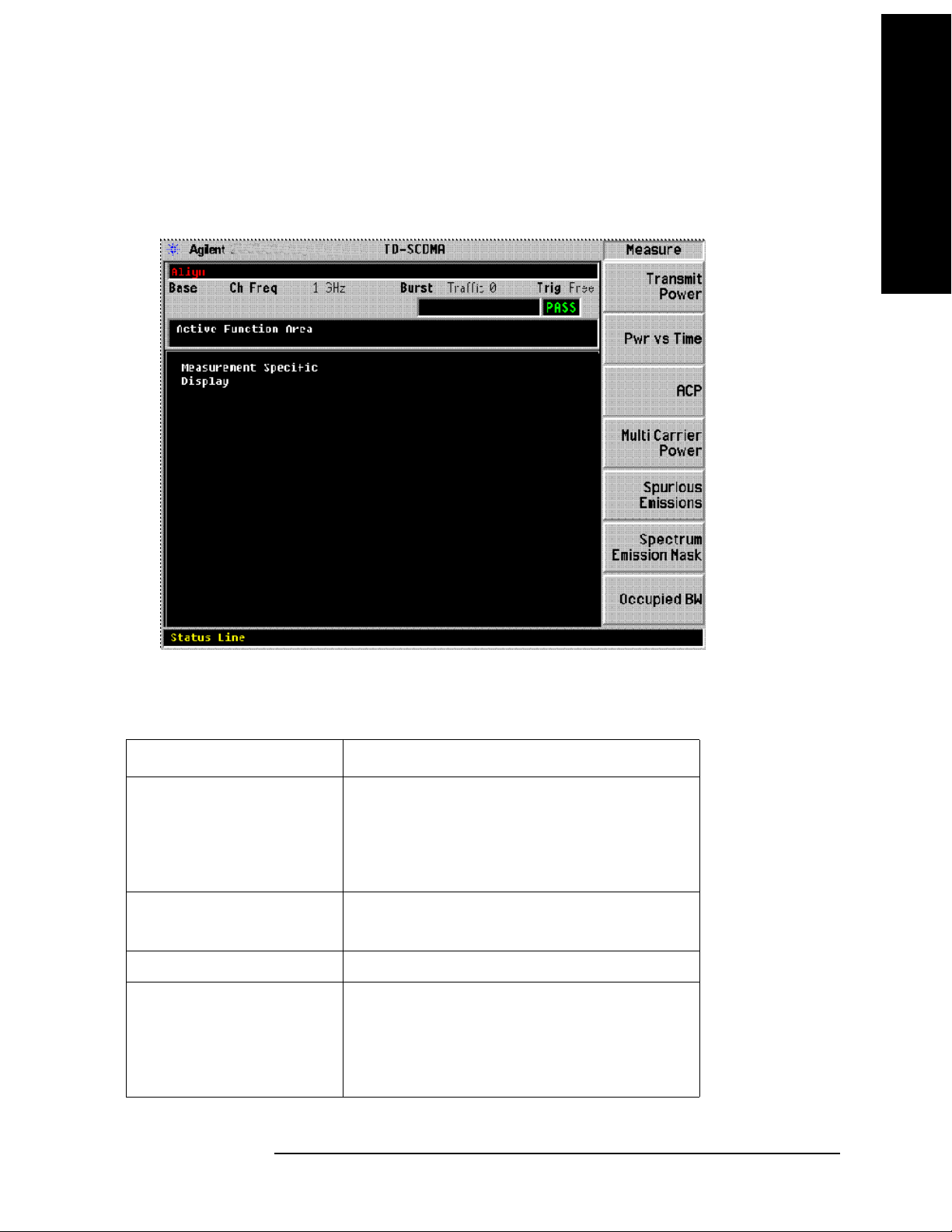
Key and SCPI Reference
Common Functionality
Screen Layout Details
This layout includes an area near the top of the display for the active function, error information, and
configuration information. See below:
Key and SCPI Reference
Annunciators
The following annunciators appear in red in the left part of the hardware status bar when appropriate.
Annunciator Corresponding Instrument Status message
Align Align Now All Needed
Align Now RF Needed
Align Now RF Skipped
System Alignments, Align Now, All Required
Overload IF Overload
Overload
Uncal Meas Uncal
Unlevel 50 MHz Osc Unlevel
LO Out Unlevel
Source LO Unlevel
Source Unlevel
Chapter 3 85

Key and SCPI Reference
Key and SCPI Reference
Common Functionality
Annunciator Corresponding Instrument Status message
Unlock 1st LO Unlock (PSA)
2nd LO Unlock (PSA)
4th LO Unlock (PSA)
Freq Ref Unlock Freq Ref Error (Freq Ref Unlocked)
The following annunciators appear in green in the right part of the hardware status bar when appropriate.
Annunciator Corresponding Instrument Status message
Ext Ref External Reference
Next Window / Zoom Front-panel keys
When measurements in the personality have a display that consists of more than one window, the
analyzer Zoom and Next Window front-panel keys may be used to control the way the windows appear.
The Zoom front-panel key causes the current window (indicated by a bright green outline when the
standard color palette is used) to fill the entire display area (covering the other windows in the process).
All measurements will be written to take advantage of the stingray display system’s method of anchoring
display items to specific points on the window. This allows the display items to be automatically
resized/repositioned/redrawn when the window is resized.
The Next Window front-panel key may be used to change the current (highlighted) measurement
window. The Next Window of the display need not be visible on the screen for it to be made current.
Display Window Tile
Selects the viewing format that displays multiple windows of the current measurement data
simultaneously. Use DISP:FORM:ZOOM to return the display to a single window.
Mode TDSCDMA
Remote Command :DISPlay:FORMat:TILE
Example :DISPlay:FORMat:TILE
Restriction and Notes Return the display to a state that shows all available windows. Use
DISPlay:FORMat:ZOOM to zoom in on the selected window.
State Saved Saved in instrument state.
Key Path
Zoom
86 Chapter 3

Key and SCPI Reference
Common Functionality
Display Window Select
Selects the current window for displays that contain more than one window. The current window is
highlighted with a green border when the color palette is set to the default.
Parameter Type Int32
Mode TDSCDMA
Remote Command :DISPlay:FORMat[:SELect] <integer>
Example :DISPlay:FORMat:SELect 2
Restriction and Notes The maximum value is the number of windows on the display.
Preset 2
State Saved Saved in instrument state.
Min 1
Max 2
Key and SCPI Reference
Key Path
Next Window
Display Window Zoom
Selects the viewing format that displays only one window of the current measurement data (the current
active window). Use DISP:FORMat:TILE to return the display to multiple windows.
Mode TDSCDMA
Remote Command DISPlay:FORMat:ZOOM
Example :DISPlay:FORMat:ZOOM
State Saved Saved in instrument state.
Key Path
Zoom
Chapter 3 87

Key and SCPI Reference
Common Functionality
UI Integration with Base Instrument
The measurements will be available on the MEASURE menu only when the TD-SCDMA mode has
been selected from the Mode menu.
Key and SCPI Reference
Parameter Types
The table below defines the categories which will be used to define the expected behavior of
measurement and base instrument parameters, with the exception of markers. Marker behavior is
described in the Markers Section.
Description Changed
by User
during
the Meas
Fully
Configurable
Parameters
Locked Out
Parameters
These are the most
important settings and
are typically found
under the meas setup
key.
These are base
instrument settings
that cannot be
changed whilst the
measurement is
running. Their SCPI
commands have been
knit over and their
front panel access has
been blocked by
context sensitive
menus.
Ye s N o N o Ye s Yes Ye s
N/A Meas
Changed
by Meas
during
the Meas
Dependent
Reset
on
Meas
Entry
Ye s Ye s Yes N /A
Coupled
BI
parameter
s restored
on Meas
exit to
Meas entry
value
Preset
and
State
Recall
active
Change
Causes
a
Restart
Restart
Parameters
Passive
Parameters
These are parameters
which when changed
will cause a
measurement restart
These are base
instrument settings
that are not used in the
measurement results
algorithm
88 Chapter 3
Ye s N o N o N o Ye s Ye s
Ye s N o N o N o Ye s N o
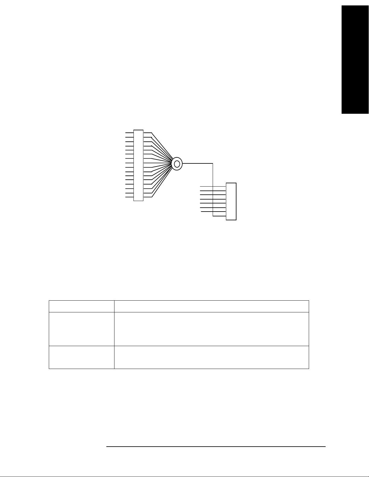
Key and SCPI Reference
Common Functionality
Status Reporting
After any of the measurements have been initiated (with the INIT:IMM command or :READ?, or
MEAS? queries), the status of operation may be queried using the STATus subsystem SCPI commands.
The following bits in the registers as shown below shall be utilized.
OPERatio n Statu s
Waiting for T RIGger
ME AS u ri ng
0
1
2
3
4
5
6
7
8
9
10
11
12
13
14
15
+
Error/ Event Queue
Questionable
Standard ESR
A va i l a bl e
A va i l a bl e
MA V
RQS
Status Byte
0
1
2
3
4
5
6
7
Key and SCPI Reference
The following table defines the meanings of the bits in the previous status diagram:
Bit Meaning
MEASuring MEASuring status:
Set to 1 if the instrument is actively measuring i.e. Not in the “idle” state.
Set to 0 if the instrument is in the “idle” state.
Waiting for TRIGger Set to 1 if the instrument is in the “wait for trigger” state of the trigger model.
Set to 0 otherwise.
Chapter 3 89

Key and SCPI Reference
Common Functionality
The following diagram shows the status of the “MEASuring” and “Waiting for TRIGger” bits at each
individual state. Note that it is possible to determine the status of these two bits given the current
measurement state, not vice versa.
Key and SCPI Reference
m = 1
w = 1
m = 1
w = 0
Wait For
Trigger
m = 1
w = 0
Meas uring
m = 0
w = 0
Any St ate
in An y
Meas
KEY:
m = M EAS uri ng bit
w = Waiti ng for TRIGg er Sum mary bit
Idle Init iated
m = 1
w = 0
Any St ate
in Cu rrent
Meas
Paus ed
STATus Subsystem
The STATus command subsystem enables you to examine the status of the spectrum analyzer by
monitoring the “Operation Status Register”.
Status Register Set Commands This section lists the five commands that can be applied to all the
SCPI registers. These commands should be prefixed with the node or nodes that represent the SCPI
Register Set you wish to control.
The five Status Register Set commands are as follows. See SCPI Reference Section 20.1 – 20.5 for
detailed definition.
STATus:OPERation:CONDition? See SCPI Reference Section 20.1.
STATus:OPERation:ENABLE <NRf> | <non-decimal numeric> See SCPI Reference Section 20.2.
STATus:OPERation [:EVENt?] See SCPI Reference Section 20.3.
STATus:OPERation:NTRansition <NRf> | <non-decimal numeric> See SCPI Reference Section 20.4.
STATus:OPERation:PTRansition <NRf> | <non-decimal numeric> See SCPI Reference Section 20.5.
Operation Register Sets The following registers contain information that is part of the instrument’s
normal operation. The contents of these registers may be accessed by appending the commands listed
below
90 Chapter 3

Key and SCPI Reference
Common Functionality
STATus:OPERation The following bits in this register are utilized by the measurements:
Bit Number Decimal Weight Description Graph / Combined
0–3 - Not used Averaged Data
416MEASuringN/A
5 32 Waiting for TRIGger Averaged Data
6–15 - Not used Averaged Data
Other Common Menus
File/Save Functions
The File/Save menu is left unchanged from the base analyzer, other than the addition of a new file type.
This allows the user to save the measurement results in a comma-delimited fashion, suitable for opening
in a spreadsheet program on a personal computer/laptop/palmtop.
This is implemented as Mime functionality, therefore all measurements which are written to support the
Mime display objects will implicitly support saving of measurement results. Any measurement that does
not have any results available should gray out and disable this particular menu key.
Key and SCPI Reference
Results are output in a tabular form, with the headings supplied by the Display object static text and the
entries supplied by the Display object values.
Example results files are included in each measurement chapter later in this document. Order and layout
in the file should be as close as possible to the layout on the screen.
Note: The ‘Measurement Results’ file type also exists when using the file system to Delete, Catalog,
Copy and Rename files.
Frequency Functions
Center Frequency
Allows you to specify the center frequency of the spectrum analyzer. For measurements that tune to
more than one frequency during their execution, the frequency of the carrier should be entered here.
Unit Hz | kHz | MHz | GHz
Mode TDSCDMA
Remote Command [:SENSe]:FREQuency[:CENTer] <freq>
[:SENSe]:FREQuency[:CENTer]?
Example :SENSe:FREQuency:CENTer 900 MHz
Preset 1.000 GHz
State Saved Saved in instrument state.
Min –100 MHz
Chapter 3 91

Key and SCPI Reference
Common Functionality
Max HW Dependant
Key and SCPI Reference
Key Path
FREQUENCY
Transmit Band Start Frequency
Allows you to specify the start frequency for the transmit band. This value is used for determining the
spectrum that should be skipped in order to meet the specification requirements for spurious emissions
for base station measurements and when the measured spectrum should be extended in order to meet the
spectrum emission mask measurement requirements.
Unit Hz | kHz | MHz | GHz
Mode TDSCDMA
Remote Command [:SENSe]:FREQuency:BAND:STARt <freq>
[:SENSe]:FREQuency:BAND:STARt?
Example :SENSe:FREQuency:BAND:STARt 1805 MHz
Preset 1785 MHz
State Saved Saved in instrument state.
Min –100 MHz
Max HW Dependant
Key Path
FREQUENCY
Transmit Band Stop Frequency
Allows you to specify the stop frequency for the transmit band. This value is used for determining the
spectrum that should be skipped in order to meet the specification requirements for spurious emissions
for base station measurements and when the measured spectrum should be extended in order to meet the
spectrum emission mask measurement requirements.
Unit Hz | kHz | MHz | GHz
Mode TDSCDMA
Remote Command [:SENSe]:FREQuency:BAND:STOP <freq>
[:SENSe]:FREQuency:BAND:STOP?
Example SENSe:FREQuency:BAND:STOP 1825 MHz
Preset 1805 MHz
State Saved Saved in instrument state.
Min –100 MHz
Max HW Dependant
Key Path
FREQUENCY
92 Chapter 3

Key and SCPI Reference
Common Functionality
Center Frequency Step Size
Allows you to set the size for the center frequency parameter step function.
Unit Hz | kHz | MHz | GHz
Mode TDSCDMA
Remote Command [:SENSe]:FREQuency[:CENTer]:STEP[:INCRement] <freq>
[:SENSe]:FREQuency[:CENTer]:STEP[:INCRement]?
[:SENSe]:FREQuency[:CENTer]:STEP:AUTO ON|OFF|1|0
[:SENSe]:FREQuency[:CENTer]:STEP:AUTO?
Example :SENSe:FREQuency:CENTer:STEP:INCRement 1.6 MHz
:SENSe:FREQuency:CENTer:STEP:AUTO ON
Preset 1.6 MHz
State Saved Saved in instrument state.
Min 1 kHz
Key and SCPI Reference
Max 1 GHz
Key Path
FREQUENCY
Channel Burst Type
Selects the type of burst to be measured. Choices are Traffic (TRAFfic), Downlink Pilot (DPTS), and
Uplink Pilot (UPTS).
Mode TDSCDMA
Remote Command [:SENSe]:CHANnel:BURSt TRAFfic|DPTS|UPTS
[:SENSe]:CHANnel:BURSt?
Example :SENSe:CHANnel:BURSt TRAF
Chapter 3 93

Key and SCPI Reference
Key and SCPI Reference
Common Functionality
Restriction and Notes This parameter automatically sets the base box hardware trigger delay to an
appropriate value such that the timeslot specified by the Burst Type and
Traffic Slot parameter combination is the first complete timeslot viewed at
the left-most side of both the Power vs Time and Transmit Power
measurements traces. (Assuming ideal Ext Trigger is being used with trigger
event representing start of traffic slot 0, and that the specified burst type is
active).
This parameter also affects the base box hardware sweeptime used for the
Power vs Time and Transmit Power measurements. The sweeptime setting
employed is determined by the specified Burst Type, along with the number
of slots to be viewed (Meas Time parameter), and the known configuration
of the TD-SCDMA burst.
In some frequency-domain measurements, Burst Type and Traffic Slot keys
will determine the Gate Length and Gate Delay. When Burst Type menu key
is pressed, Gate State will turn On automatically if current trigger source is
NOT Freerun.
For more information please refer to the “Gate Delay” section.
This key is unavailable (grayed out) while switching to the Spurious
Emissions measurement
Dependencies/Couplings See “Restriction and Notes”
Preset TRAFfic
State Saved Saved in instrument state.
Range Traffic | Downlink Pilot | Uplink Pilot
Key Path
FREQUENCY
Traffic Timeslot
Sets the number of the traffic slot that will appear on the left of the display. (see Channel Burst Type for
more details)
Mode TDSCDMA
Remote Command [:SENSe]:CHANnel:SLOT <integer>
[:SENSe]:CHANnel:SLOT?
Example :SENSe:CHANnel:SLOT 2
Restriction and Notes This parameter is unavailable (greyed out) when the Burst Type parameter is
set to Uplink / Downlink or the Spurious Emissions measurement is selected.
Dependencies/Couplings Traffic Timeslot menu key is enabled when the current Burst Type is Traffic.
Preset 0
State Saved Saved in instrument state.
Min 0
Max 6
94 Chapter 3

Key and SCPI Reference
Common Functionality
Key Path FREQUENCY
Span Functions
Span Menu
The base analyzer span menu is not available when the TD-SCDMA mode is active. Measurements
requiring a Span / X Scale menu have a menu map and command descriptions included in the individual
measurement chapters later in this document.
Remote Control
Remote commands for those measurements that place keys on the Span / X Scale menu are listed under
those measurements.
Markers
The base analyzer Marker menu is not available while the analyzer is in TD-SCDMA mode.
Measurements that require marker functionality have their own Marker menu that will be available only
when that measurement is running. These measurement-specific Marker menus are described in detail
later in this document, in the chapters describing the individual measurements. When a measurement has
no specific marker requirements, the Marker menu will appear blank.
Key and SCPI Reference
Markers are all measurement-specific. That is, turning on a marker for one measurement does not turn it
on for any other measurement. Marker states for each measurement are saved at measurement exit and
recalled at measurement entry. If a marker is turned on in a measurement and the measurement is
subsequently exited, the marker will be restored the next time that measurement, begins, provided that
no *RST or state recall has happened before then. See the individual measurement chapters later in this
document for specific SCPI commands for markers.
FORMat Subsystem
The FORMat subsystem sets a data format for transferring numeric and array information. The
TRACe [:DATA] command is affected by FORMat subsystem commands.
Byte Order
Selects the binary data byte order for numeric data transfer. In normal mode the most significant byte is
sent first. In swapped mode the least significant byte is first. (PCs use the swapped order.) Binary data
byte order functionality does not apply to ASCII.
Mode TDSCDMA
Remote Command FORMat:BORDer NORM|SWAP
FORMat:BORDer?
Example FORMat:BORDer SWAPped
Restriction and Notes Selects the binary data byte order for numeric data transfer. In normal mode
the most significant byte is sent first. In swapped mode the least significant
byte is first. (PCs use the swapped order.) Binary data byte order
functionality does not apply to ASCII.
Chapter 3 95

Key and SCPI Reference
Key and SCPI Reference
Common Functionality
Preset NORM
State Saved Saved in instrument state.
Range NORMal | SWAPped
Trace Data Format
Sets the format for the data transfer across any remote port. The REAL and ASCII formats will format
trace data in the current amplitude units.
ASCII - Amplitude values are in ASCII, in amplitude units, separated by commas. ASCII format
requires more memory than the binary formats. Therefore, handling large amounts of this type of data,
will take more time and storage space.
Integer,16 - Binary 16-bit integer values in internal units (dBm), in a definite length block.
Integer,32 - Binary 32-bit integer values in internal units (dBm), in a definite length block.
Real,32 (or 64) - Binary 32-bit (or 64-bit) real values in amplitude unit, in a definite length block.
Transfers of real data are done in a binary block format.
UINTeger,16 - Binary 16-bit unsigned integer that is uncorrected ADC values, in a definite length block.
This format is almost never applicable with current data.
Mode TDSCDMA
Remote Command :FORMat[:TRACe][:DATA] ASC,8|REAL,32|REAL,64
:FORMat[:TRACe][:DATA]?
Example FORMat:TRACe:DATA INT32
Preset REAL,32
State Saved Saved in instrument state.
Range ASCii,8| REAL,32 | REAL,64
96 Chapter 3

Key and SCPI Reference
Common Functionality
Measurement Display Availability
The following table is included to show the Windows available for each of the different views for each
measurement. This information is intended for use in creating IVI-COM drivers for the DISPlay system
of commands.
Key and SCPI Reference
Measurement View Window X-scale
function
Avail ab le ?
Transmit Power (Single) Top (Window 1) Yes Yes
Bottom (Window 2) ––– –––
ACLR (ACP) Combined Top (Window 1) No Yes
Bottom (Window 2) ––– –––
Bar Graph Top (Window 1) No No
Bottom (Window 2) ––– –––
Spectrum Top (Window 1) No Yes
Bottom (Window 2) ––– –––
Spectrum
Emission Mask
Multi Carrier
Power
(Single) Top (Window 1) No Yes
Bottom (Window 2) ––– –––
Spectrum Top (Window 1) No Yes
Bottom (Window 2)
Y-scale
function
Available?
Combined Top (Window 1) No Yes
Bottom (Window 2) ––– –––
Spurious (Single) Top (Window 1) No Yes
Power vs Time Burst Top (Window 1) Yes Yes
Occupied
Bandwidth
(Single) Top (Window 1) No Yes
Bottom (Window 2) ––– –––
Chapter 3 97

Key and SCPI Reference
Measurements
Measurements
Key and SCPI Reference
Measure Menu
Restart Measurement
Pressing the ‘Restart’ menu key in the Meas Control menu, or pressing the ‘Restart’ front-panel key
re-starts the measurement running from the Idle state. This does not change any parameter values but
does reset the average counter.
Continuous vs. Single Measurement Mode
The mode of operation of the measurement may be configured from the ‘Continuous/Single’ menu keys
in the Meas Control menu. The setting of Continuous/Single is valid for all measurements. If set to:
SINGLE–one measurement will be taken (this will involve a number of sweeps if averaging is ON or if
the measurement uses multiple set-points, otherwise just one sweep if averaging is OFF) and
measurement results will be displayed. The measurement will then enter the “idle” state.
CONTINUOUS–the measurement run continuously, displaying the measurement results after each
trigger cycle. The “idle” state will not be entered.
Pressing this menu key will start the measurement if it is in the “idle” state, or will follow the procedure
detailed in the following table if it is in a measurement (trigger) cycle.
Meas Change Averaging ‘N’ is Measurement Adjustment
Single to Cont ON Less than or equal
to ‘K’
Measurement switched into Continuous mode as soon
as “idle” state reached. No adjustment necessary.
Cont to Single ON Less than or equal
to ‘K’
Cont to Single ON Greater than ‘K’ Restart the measurement in Single mode with the
Cont to Single OFF - Switch to Single mode immediately. Measurement will
Switch to Single mode immediately. Measurement will
terminate and return to the idle state when K averages
reached.
averages ‘N’ set back to 1.
terminate and return to the idle state after current trigger
cycle
If the number of averages (K) is altered during a measurement, the new value of K will be used the next
time K it is used in any calculation. Note that this will not cause the measurement to restart.
Pause / Resume Measurement
If the ‘Pause’ menu key is pressed during a measurement, the “paused” state is. The measurement can be
resumed by pressing the same menu key, which will now be labeled ‘Resume’. The ‘Restart’ front-panel
key may also be used to start the measurement from the beginning.
When in the paused state, the analyzer will not sweep. As a result, any trace visible on the display will
remain unchanged.
98 Chapter 3

Key and SCPI Reference
Measurements
Single Front-panel key
Should put the measurement into ‘Single’ mode, and also initiate a measurement sweep if the
measurement is idle.
Remote Control
Continuous Sweep Mode
Turns the continuous sweep mode on or off.
Readback Text 0 | 1
Mode TDSCDMA
Remote Command :INITiate:CONTinuous ON|OFF|1|0
:INITiate:CONTinuous?
Example :INITiate:CONTinuous OFF
Preset ON
Key and SCPI Reference
State Saved Saved in instrument state.
Range Single | Cont
Key Path
Meas Control
Measurement Pause
Pauses the current measurement. Sweeping will stop after the end of the current sweep.
Mode TDSCDMA
Remote Command :INITiate:PAUSe
Example :INITiate:PAUSe
Remote Command Notes No corresponding query.
State Saved No
Key Path
Meas Control
Measurement Resume
Resumes a paused measurement.
Mode TDSCDMA
Remote Command :INITiate:RESume
Example :INITiate:RESume
Remote Command Notes No corresponding query.
State Saved No
Chapter 3 99

Key and SCPI Reference
Measurements
Key Path Meas Control
Initiate Measurement Sweep
Key and SCPI Reference
Initiates a measurement. Any current measurement is interrupted.
Mode TDSCDMA
Remote Command :INITiate[:IMMediate]
Example :INITiate:IMMidiate
Remote Command Notes No corresponding query.
State Saved No
Key Path
Meas Control
Initiate Measurement Restart
Re-initiate the current measurement. Any measurement in progress is interrupted.
Mode TDSCDMA
Remote Command :INITiate:RESTart
Example :INITiate:RESTart
Remote Command Notes No corresponding query.
State Saved No
Key Path
Meas Control, Restart
Initiate Power vs Time Measurement
Initiates a power versus time measurement. Any current measurement is interrupted.
Mode TDSCDMA
Remote Command :INITiate:PVTime
Example :INITiate:PVTime
Remote Command Notes No corresponding query.
State Saved No
Key Path
Measure, Pwr vs Time
100 Chapter 3
 Loading...