

Page 1

EMI Measurement Receiver Guide
PSA Series Spectrum Analyzers
Option 239
This manual provides documentation for the following instruments:
Spectrum Analyzers:
E4440A (3 Hz – 26.5 GHz)
E4443A (3 Hz – 6.7 GHz)
E4445A (3 Hz – 13.2 GHz)
E4446A (3 Hz – 44.0 GHz)
E4447A (3 Hz – 42.98GHz)
E4448A (3 Hz – 50.0 GHz)
Systems:
EMI Receiver System
Manufacturing Part Number: E4440-90625
Supersedes E4440-90330
Printed in USA
June 2008
© Copyright 2007, 2008 Agilent Technologies, Inc.
Page 2

The information contained in this document is subject to change
without notice.
Agilent Technologies makes no warranty of any kind with regard to this
material, including but not limited to, the implied warranties of
merchantability and fitness for a particular purpose. Agilent
Technologies shall not be liable for errors contained herein or for
incidental or consequential damages in connection with the furnishing,
performance, or use of this material.
2
Page 3

Contents
1. Introduction
What Does the EMI Receiver Do? . . . . . . . . . . . . . . . . . . . . . . . . . . . . . . . . . . . . . . . . . . . . . . . 10
Installing Optional Measurement Personalities . . . . . . . . . . . . . . . . . . . . . . . . . . . . . . . . . . . 11
Do You Have Enough Memory to Load All Your Personality Options? . . . . . . . . . . . . . . . . 11
How to Predict Your Memory Requirements . . . . . . . . . . . . . . . . . . . . . . . . . . . . . . . . . . . . . 13
Loading an Optional Measurement Personality . . . . . . . . . . . . . . . . . . . . . . . . . . . . . . . . . . 15
Obtaining and Installing a License Key . . . . . . . . . . . . . . . . . . . . . . . . . . . . . . . . . . . . . . . . 15
Viewing a License Key . . . . . . . . . . . . . . . . . . . . . . . . . . . . . . . . . . . . . . . . . . . . . . . . . . . . . . 16
Using the Delete License Key on PSA . . . . . . . . . . . . . . . . . . . . . . . . . . . . . . . . . . . . . . . . . . 16
Ordering Optional Measurement Personalities . . . . . . . . . . . . . . . . . . . . . . . . . . . . . . . . . . 17
2. Making Measurements
Introduction . . . . . . . . . . . . . . . . . . . . . . . . . . . . . . . . . . . . . . . . . . . . . . . . . . . . . . . . . . . . . . . . 20
Instrument Requirements . . . . . . . . . . . . . . . . . . . . . . . . . . . . . . . . . . . . . . . . . . . . . . . . . . . . . 21
Test Equipment Setup . . . . . . . . . . . . . . . . . . . . . . . . . . . . . . . . . . . . . . . . . . . . . . . . . . . . . . . . 22
Connecting the System . . . . . . . . . . . . . . . . . . . . . . . . . . . . . . . . . . . . . . . . . . . . . . . . . . . . . . 22
Configuring the System . . . . . . . . . . . . . . . . . . . . . . . . . . . . . . . . . . . . . . . . . . . . . . . . . . . . . 25
Aligning the System . . . . . . . . . . . . . . . . . . . . . . . . . . . . . . . . . . . . . . . . . . . . . . . . . . . . . . . . 27
Using Instrument Presets Functions. . . . . . . . . . . . . . . . . . . . . . . . . . . . . . . . . . . . . . . . . . . 30
Making Measurements . . . . . . . . . . . . . . . . . . . . . . . . . . . . . . . . . . . . . . . . . . . . . . . . . . . . . . . 34
Emissions Measurements With an RF Preselector . . . . . . . . . . . . . . . . . . . . . . . . . . . . . . . . 34
File Operation. . . . . . . . . . . . . . . . . . . . . . . . . . . . . . . . . . . . . . . . . . . . . . . . . . . . . . . . . . . . . . . 44
Saving a Setup file . . . . . . . . . . . . . . . . . . . . . . . . . . . . . . . . . . . . . . . . . . . . . . . . . . . . . . . . . 44
Loading a Setup file . . . . . . . . . . . . . . . . . . . . . . . . . . . . . . . . . . . . . . . . . . . . . . . . . . . . . . . . 44
Loading a Limit file from the floppy disk . . . . . . . . . . . . . . . . . . . . . . . . . . . . . . . . . . . . . . . 45
Loading a Corrections file from the floppy disk . . . . . . . . . . . . . . . . . . . . . . . . . . . . . . . . . . 45
Interpreting Error Codes . . . . . . . . . . . . . . . . . . . . . . . . . . . . . . . . . . . . . . . . . . . . . . . . . . . . . . 46
Table of Contents
3. Front-Panel Key and SCPI Command Reference
Instrument Front Panel Highlights . . . . . . . . . . . . . . . . . . . . . . . . . . . . . . . . . . . . . . . . . . . . . 52
Selected and PSA Front-Panel Features . . . . . . . . . . . . . . . . . . . . . . . . . . . . . . . . . . . . . . . . 52
Front-Panel Keys . . . . . . . . . . . . . . . . . . . . . . . . . . . . . . . . . . . . . . . . . . . . . . . . . . . . . . . . . . . . 54
Center Frequency, Span for lower window . . . . . . . . . . . . . . . . . . . . . . . . . . . . . . . . . . . . . . 54
File . . . . . . . . . . . . . . . . . . . . . . . . . . . . . . . . . . . . . . . . . . . . . . . . . . . . . . . . . . . . . . . . . . . . . 56
Input/ Output . . . . . . . . . . . . . . . . . . . . . . . . . . . . . . . . . . . . . . . . . . . . . . . . . . . . . . . . . . . . . 57
Marker Function . . . . . . . . . . . . . . . . . . . . . . . . . . . . . . . . . . . . . . . . . . . . . . . . . . . . . . . . . . . 58
Meas Control . . . . . . . . . . . . . . . . . . . . . . . . . . . . . . . . . . . . . . . . . . . . . . . . . . . . . . . . . . . . . . 59
Mode. . . . . . . . . . . . . . . . . . . . . . . . . . . . . . . . . . . . . . . . . . . . . . . . . . . . . . . . . . . . . . . . . . . . . 60
Mode Setup . . . . . . . . . . . . . . . . . . . . . . . . . . . . . . . . . . . . . . . . . . . . . . . . . . . . . . . . . . . . . . . 61
System . . . . . . . . . . . . . . . . . . . . . . . . . . . . . . . . . . . . . . . . . . . . . . . . . . . . . . . . . . . . . . . . . . . 70
Measure . . . . . . . . . . . . . . . . . . . . . . . . . . . . . . . . . . . . . . . . . . . . . . . . . . . . . . . . . . . . . . . . . . . 71
Command Interactions: MEASure, CONFigure, FETCh, INITiate and READ . . . . . . . . . 71
Emissions. . . . . . . . . . . . . . . . . . . . . . . . . . . . . . . . . . . . . . . . . . . . . . . . . . . . . . . . . . . . . . . . . 74
Measurement Key . . . . . . . . . . . . . . . . . . . . . . . . . . . . . . . . . . . . . . . . . . . . . . . . . . . . . . . . . . . 75
Emissions Measurement. . . . . . . . . . . . . . . . . . . . . . . . . . . . . . . . . . . . . . . . . . . . . . . . . . . . . 75
4. Menu Maps
EMI Measurement Key Flow. . . . . . . . . . . . . . . . . . . . . . . . . . . . . . . . . . . . . . . . . . . . . . . . . . . 78
3
Page 4

Contents
Table of Contents
A. Disk Contents: Limit Lines and Transducer Factors
Directions for Use . . . . . . . . . . . . . . . . . . . . . . . . . . . . . . . . . . . . . . . . . . . . . . . . . . . . . . . . . .79
Limit Line Table . . . . . . . . . . . . . . . . . . . . . . . . . . . . . . . . . . . . . . . . . . . . . . . . . . . . . . . . . . . . .98
Transducer Factors Table . . . . . . . . . . . . . . . . . . . . . . . . . . . . . . . . . . . . . . . . . . . . . . . . . . . . .103
4
Page 5

List of Commands
:CALibration:PRESelector:EXTernal:AB . . . . . . . . . . . . . . . . . . . . . . . . . . . . . . . . . . . . . . . . . . . . . . 69
:CALibration:PRESelector:EXTernal:AB[:STATe]?. . . . . . . . . . . . . . . . . . . . . . . . . . . . . . . . . . . . . . . 69
:CALibration:PRESelector:EXTernal:ALL . . . . . . . . . . . . . . . . . . . . . . . . . . . . . . . . . . . . . . . . . . . . . 70
:CALibration:PRESelector:EXTernal:ALL[:STATe]? . . . . . . . . . . . . . . . . . . . . . . . . . . . . . . . . . . . . . 70
:CALibration:PRESelector:EXTernal:CD . . . . . . . . . . . . . . . . . . . . . . . . . . . . . . . . . . . . . . . . . . . . . . 69
:CALibration:PRESelector:EXTernal:CD[:STATe]? . . . . . . . . . . . . . . . . . . . . . . . . . . . . . . . . . . . . . . 69
:CALibration:PRESelector:EXTernal:DEFault . . . . . . . . . . . . . . . . . . . . . . . . . . . . . . . . . . . . . . . . . . 70
:CONFigure:EMI. . . . . . . . . . . . . . . . . . . . . . . . . . . . . . . . . . . . . . . . . . . . . . . . . . . . . . . . . . . . . . . . . . 74
:FETCh:EMI[n]? . . . . . . . . . . . . . . . . . . . . . . . . . . . . . . . . . . . . . . . . . . . . . . . . . . . . . . . . . . . . . . . . . . 74
:INITiate:CONTinuous OFF|ON. . . . . . . . . . . . . . . . . . . . . . . . . . . . . . . . . . . . . . . . . . . . . . . . . . . . . 59
List of Commands
:INITiate:EMI . . . . . . . . . . . . . . . . . . . . . . . . . . . . . . . . . . . . . . . . . . . . . . . . . . . . . . . . . . . . . . . . . . . . 74
:INITiate:PAUSe . . . . . . . . . . . . . . . . . . . . . . . . . . . . . . . . . . . . . . . . . . . . . . . . . . . . . . . . . . . . . . . . . . 60
:INITiate:RESTart . . . . . . . . . . . . . . . . . . . . . . . . . . . . . . . . . . . . . . . . . . . . . . . . . . . . . . . . . . . . . . . . 59
:INITiate:RESume . . . . . . . . . . . . . . . . . . . . . . . . . . . . . . . . . . . . . . . . . . . . . . . . . . . . . . . . . . . . . . . . 60
:INPut:PRESelector[:EXTernal] RF|SOURce . . . . . . . . . . . . . . . . . . . . . . . . . . . . . . . . . . . . . . . . . . 57
:INPut:PRESelector[:EXTernal]:PATH FILTer|BYPass . . . . . . . . . . . . . . . . . . . . . . . . . . . . . . . . . . 57
:INPut:PRESelector[:EXTernal]:PATH? . . . . . . . . . . . . . . . . . . . . . . . . . . . . . . . . . . . . . . . . . . . . . . . 57
:INPut:PRESelector[:EXTernal]?. . . . . . . . . . . . . . . . . . . . . . . . . . . . . . . . . . . . . . . . . . . . . . . . . . . . . 57
:INSTrument:NSELect 239 . . . . . . . . . . . . . . . . . . . . . . . . . . . . . . . . . . . . . . . . . . . . . . . . . . . . . . . . . 61
:INSTrument:NSELect? . . . . . . . . . . . . . . . . . . . . . . . . . . . . . . . . . . . . . . . . . . . . . . . . . . . . . . . . . . . . 61
:INSTrument[:SELect] SA|EMC . . . . . . . . . . . . . . . . . . . . . . . . . . . . . . . . . . . . . . . . . . . . . . . . . . . . . 60
:INSTrument[:SELect]? . . . . . . . . . . . . . . . . . . . . . . . . . . . . . . . . . . . . . . . . . . . . . . . . . . . . . . . . . . . . 60
:MEASure:EMI:MARKer . . . . . . . . . . . . . . . . . . . . . . . . . . . . . . . . . . . . . . . . . . . . . . . . . . . . . . . . . . . 58
:MEASure:EMI:MARKer[1]|2|3|4? . . . . . . . . . . . . . . . . . . . . . . . . . . . . . . . . . . . . . . . . . . . . . . . . . . 58
:MEASure:EMI[n]? . . . . . . . . . . . . . . . . . . . . . . . . . . . . . . . . . . . . . . . . . . . . . . . . . . . . . . . . . . . . . . . . 74
:MMEMory:LOAD:SETup <‘file_name’> . . . . . . . . . . . . . . . . . . . . . . . . . . . . . . . . . . . . . . . . . . . . . . . 56
:MMEMory:STORe:SETup <‘file_name’> . . . . . . . . . . . . . . . . . . . . . . . . . . . . . . . . . . . . . . . . . . . . . . 56
:READ:EMI[n]? . . . . . . . . . . . . . . . . . . . . . . . . . . . . . . . . . . . . . . . . . . . . . . . . . . . . . . . . . . . . . . . . . . . 74
:SYSTem:COMMunicate:ESOurce:CONNection LAN|LG . . . . . . . . . . . . . . . . . . . . . . . . . . . . . . . . 66
:SYSTem:COMMunicate:ESOurce:CONNection? . . . . . . . . . . . . . . . . . . . . . . . . . . . . . . . . . . . . . . . . 66
:SYSTem:COMMunicate:ESOurce:TCONnect . . . . . . . . . . . . . . . . . . . . . . . . . . . . . . . . . . . . . . . . . . 68
5
Page 6

List of Commands
:SYSTem:COMMunicate:ESOurce:TCONnect:TOUT <time> . . . . . . . . . . . . . . . . . . . . . . . . . . . . . . .67
:SYSTem:COMMunicate:ESOurce:TCONnect:TOUT? . . . . . . . . . . . . . . . . . . . . . . . . . . . . . . . . . . . .67
:SYSTem:COMMunicate:ESOurce:TCONnect? . . . . . . . . . . . . . . . . . . . . . . . . . . . . . . . . . . . . . . . . . .68
:SYSTem:COMMunicate:ESOurce:TYPE
B8648|MXG|N5181A|N5182A|ESG|E4438C|PSG|E8257D . . . . . . . . . . . . . . . . . . . . . . . . . . . . .65
:SYSTem:COMMunicate:ESOurce:TYPE? . . . . . . . . . . . . . . . . . . . . . . . . . . . . . . . . . . . . . . . . . . . . . .65
:SYSTem:COMMunicate:ESOure:IDN? . . . . . . . . . . . . . . . . . . . . . . . . . . . . . . . . . . . . . . . . . . . . . . . .68
:SYSTem:COMMunicate:GPIB:ESOurce[:EXTernal]:ADDRess <integer> . . . . . . . . . . . . . . . . . . . .66
:SYSTem:COMMunicate:GPIB:ESOurce[:EXTernal]:ADDRess? . . . . . . . . . . . . . . . . . . . . . . . . . . . .66
:SYSTem:COMMunicate:GPIB:ESOurce[:EXTernal]:LUNit <integer> . . . . . . . . . . . . . . . . . . . . . . .67
List of Commands
:SYSTem:COMMunicate:GPIB:ESOurce[:EXTernal]:LUNit? . . . . . . . . . . . . . . . . . . . . . . . . . . . . . . .67
:SYSTem:COMMunicate:LAN:ESOurce[:EXTernal]:IP <string> . . . . . . . . . . . . . . . . . . . . . . . . . . . .66
:SYSTem:COMMunicate:LAN:ESOurce[:EXTernal]:IP? . . . . . . . . . . . . . . . . . . . . . . . . . . . . . . . . . . .66
:SYSTem:COMMunicate:LAN:PRESelector[:EXTernal]:IP <string> . . . . . . . . . . . . . . . . . . . . . . . . .63
:SYSTem:COMMunicate:LAN:PRESelector[:EXTernal]:IP? . . . . . . . . . . . . . . . . . . . . . . . . . . . . . . . .63
:SYSTem:COMMunicate:PRESelector:IDN? . . . . . . . . . . . . . . . . . . . . . . . . . . . . . . . . . . . . . . . . . . . .64
:SYSTem:COMMunicate:PRESelector:TCONnect . . . . . . . . . . . . . . . . . . . . . . . . . . . . . . . . . . . . . . . .64
:SYSTem:COMMunicate:PRESelector:TCONnect:TOUT <time>. . . . . . . . . . . . . . . . . . . . . . . . . . . .64
:SYSTem:COMMunicate:PRESelector:TCONnect:TOUT? . . . . . . . . . . . . . . . . . . . . . . . . . . . . . . . . .64
:SYSTem:COMMunicate:PRESelector:TCONnect? . . . . . . . . . . . . . . . . . . . . . . . . . . . . . . . . . . . . . . .64
[:SENSe]:EMI:FREQuency:SPAN. . . . . . . . . . . . . . . . . . . . . . . . . . . . . . . . . . . . . . . . . . . . . . . . . . . . .55
[:SENSe]:EMI:FREQuency:SPAN? . . . . . . . . . . . . . . . . . . . . . . . . . . . . . . . . . . . . . . . . . . . . . . . . . . . .55
[:SENSe]:EMI:FREQuency[:CENTer]. . . . . . . . . . . . . . . . . . . . . . . . . . . . . . . . . . . . . . . . . . . . . . . . . .54
[:SENSe]:EMI:FREQuency[:CENTer]? . . . . . . . . . . . . . . . . . . . . . . . . . . . . . . . . . . . . . . . . . . . . . . . . .54
[:SENSe]:EMI:MEASure:DETector:AVERage[:STATe] OFF|ON|0|1 . . . . . . . . . . . . . . . . . . . . . . . .75
[:SENSe]:EMI:MEASure:DETector:DWELl <time> . . . . . . . . . . . . . . . . . . . . . . . . . . . . . . . . . . . . . .76
[:SENSe]:EMI:MEASure:DETector:DWELl? . . . . . . . . . . . . . . . . . . . . . . . . . . . . . . . . . . . . . . . . . . . .76
[:SENSe]:EMI:MEASure:DETector:QPEak[:STATe] OFF|ON|0|1|. . . . . . . . . . . . . . . . . . . . . . . . .75
[:SENSe]:FREQuency:PRESelector[:EXTernal]:PBANd A|B|C|D|CD|E|UPPer . . . . . . . . . . . . .61
[:SENSe]:FREQuency:PRESelector[:EXTernal]:PBANd? . . . . . . . . . . . . . . . . . . . . . . . . . . . . . . . . . .61
[:SENSe]:POWer[:RF]:PRESelector[:EXTernal]:ATTenuation <numeric value> . . . . . . . . . . . . . . . .62
6
Page 7

List of Commands
[:SENSe]:POWer[:RF]:PRESelector[:EXTernal]:ATTenuation? . . . . . . . . . . . . . . . . . . . . . . . . . . . . . 62
[:SENSe]:POWer[:RF]:PRESelector[:EXTernal]:GAIN[:STATe] ON|OFF|0|1 . . . . . . . . . . . . . . . . 63
[:SENSe]:POWer[:RF]:PRESelector[:EXTernal]:GAIN[:STATe]?. . . . . . . . . . . . . . . . . . . . . . . . . . . . 63
[:SENSe]:POWer[:RF]:PRESelector[:EXTernal]:USE YES|NO . . . . . . . . . . . . . . . . . . . . . . . . . . . . 62
[:SENSe]:POWer[:RF]:PRESelector[:EXTernal]:USE? . . . . . . . . . . . . . . . . . . . . . . . . . . . . . . . . . . . . 62
List of Commands
7
Page 8

List of Commands
List of Commands
8
Page 9

1 Introduction
This chapter provides overall information on the Agilent PSA Series
EMI Receiver Option 239, and describes the EMI compliance
measurements made by the analyzer plus an RF Preselector.
Installation instructions for adding this option to your analyzer are
provided in this section, if you purchased this option separately.
Introduction
9
Page 10

Introduction
What Does the EMI Receiver Do?
What Does the EMI Receiver Do?
The EMI Receiver system consists of an Agilent PSA Series Spectrum
Analyzer, an Agilent RF Preselector, an Agilent Signal Generator for
user alignment, and optional accessories needed to prepare the system
for use. Option 239 is an embedded application in the PSA.
The PSA is used as an EMI receiver, controlling the external RF
Preselector, to perform CISPR compliance EMI measurements to test
conducted and radiated emissions.
Conducted emissions testing focuses on signals, present on the AC
mains, that are generated by the equipment under test (EUT). The test
range for these measurements is typically from 9 kHz to 30 MHz.
Radiated emissions testing looks for signals broadcasted from the EUT
through space. The test range for these measurements is typically from
30 MHz to 1 GHz, depending on the regulation.
You can also perform EMI pre-compliance measurements if you do not
have an RF Preselector. PSA EMI measurement keys are not fully
functional without the RF Preselector.
Figure 1-1 EMI Receiver System
Introduction
10 Chapter 1
Page 11

Introduction
Installing Optional Measurement Personalities
Installing Optional Measurement
Personalities
When you install a measurement personality, you need to follow a three
step process:
1. Determine whether your memory capacity is sufficient to contain all
the options you want to load. If not, decide which options you want to
install now, and consider upgrading your memory. Details follow in
“Do You Have Enough Memory to Load All Your Personality
Options?” on page 11.
2. Install the measurement personality firmware into the instrument
memory. Details follow in “Loading an Optional Measurement
Personality” on page 15.
3. Enter a license key that activates the measurement personality.
Details follow in “Obtaining and Installing a License Key” on page
15.
Adding measurement personalities requires the purchase of an upgrade
kit for the desired option. The upgrade kit contains the measurement
personality firmware and an entitlement certificate that is used to
generate a license key from the internet website. A separate license key
is required for each option on a specific instrument serial number and
host ID.
For the latest information on Agilent Spectrum Analyzer options and
upgrade kits, visit the following web location:
http://www.agilent.com/find/sa_upgrades
Do You Have Enough Memory to Load All Your Personality Options?
If you do not have memory limitations then you can skip ahead to the
next section “Loading an Optional Measurement Personality” on
page 15. If after installing your options you get error messages relating
to memory issues, you can return to this section to learn more about
how to optimize your configuration.
If you have 64 MBytes of memory installed in your instrument, you
should have enough memory to install at least four optional
personalities, with plenty of memory for data and states.
Introduction
The optional measurement personalities require different amounts of
memory. So the number of personalities that you can load varies. This is
also impacted by how much data you need to save. If you are having
memory errors you must swap the applications in or out of memory as
needed. If you only have 48 MBytes of memory, you can upgrade your
Chapter 1 11
Page 12

Introduction
Installing Optional Measurement Personalities
hardware to 64 MBytes.
Additional memory can be added to any PSA Series analyzer by
installing Option 115. With this option installed, you can install all
currently available measurement personalities in your analyzer and
still have memory space to store more state and trace files than would
otherwise be possible.
To see the size of your installed memory for PSA Series Spectrum
Analyzers:
1. Ensure that the spectrum analyzer is in spectrum analyzer mode
because this can affect the screen size.
2. Press
3. Press
System, Show System. Under Options look for 115.
System, More, Show Hdwr.
4. Read Flash Memory size in the table.
PSA Flash
Memory Size
64 Mbytes 32.5 MBytes 30.0 MBytes
48 Mbytes 16.9 MBytes 14.3 MBytes
PSA Compact Flash
Memory Size
512 Mbytes (Opt. 115) 512 MBytes
Available Memory
Without Option
B7J and Option
122 or 140
Available Additional Memory for
Measurement Personalities
Available Memory With
Option B7J and Option 122 or
140
If you have 48 MBytes of memory, and you want to install more than 3
Introduction
optional personalities, you may need to manage your memory
resources. The following section, “How to Predict Your Memory
Requirements” on page 13, will help you decide how to configure your
installed options to provide optimal operation.
12 Chapter 1
Page 13

Introduction
Installing Optional Measurement Personalities
How to Predict Your Memory Requirements
If you plan to install many optional personalities, you should review
your memory requirements, so you can determine whether you have
enough memory (unless you have a PSA Series with Option 115). There
is an Agilent “Memory Calculator” available online that can help you do
this, or you can make a calculated approximation using the information
that follows. You will need to know your instrument’s installed memory
size as determined in the previous section and then select your desired
applications.
NOTE If you have a PSA Series analyzer with Option 115, there is adequate
memory to install all of the available optional personalities in your
instrument.
To calculate the available memory on your PSA, see:
http://sa.tm.agilent.com/PSA/memory/
Select the “Memory Calculator” link. You can try any combination of
available personalities to see if your desired configuration is compatible
with your installed memory.
NOTE For PSA: After loading all your optional measurement personalities,
you should have a reserve of ~2 MBytes memory to facilitate mode
switching. Less available memory will increase mode switching time.
For example, if you employ excessive free memory by saving files of
states and/or data, your mode switching time can increase to more than
a minute.
You can manually estimate your total memory requirements by adding
up the memory allocations described in the following steps. Compare
the desired total with the available memory that you identified in the
previous section.
1. Program memory - Select option requirements from the table
“Measurement Personality Options and Memory Required” on
page 14.
2. The PSA shared libraries require 7.72 MBytes.
3. The PSA recommended mode swap space is 2 MBytes.
4. Screens - .gif files need 20-25 kBytes each.
5. State memory - State file sizes range from 21 kB for SA mode to
40 kB for W-CDMA. The state of every mode accessed since power-on
will be saved in the state file. File sizes can exceed 150 kB each when
several modes are accessed, for each state file saved.
Introduction
TIP State memory retains settings for all states accessed before the Save
State
command. To reduce this usage to a minimum, reduce the modes
Chapter 1 13
Page 14

Introduction
Installing Optional Measurement Personalities
accessed before the Save State is executed. You can set the PSA to boot
into a selected mode by accessing the desired mode, then pressing the
System, Power On/Preset, Power On keys and toggle the setting to Last.
Measurement Personality Options and Memory Required
Personality Options
for PSA Series Spectrum Analyzers
a
Option File Size
(PSA Rev: A.10)
cdmaOne measurement personality BAC 1.91 Mbytes
NADC and PDC measurement personalities (not
BAE 2.43 Mbytes
available separately)
W-CDMA or W-CDMA, HSDPA, HSUPA
BAF, 210
5.38 Mbytes
measurement personality
cdma2000 or cdma2000 w/ 1xEV-DV measurement
personality
1xEV-DO measurement personality 204
GSM (with EDGE) measurement personality 202
Shared measurement library
b
Phase Noise measurement personality 226
Noise Figure measurement personality 219
Basic measurement personality with digital demod
hardware
Programming Code Compatibility Suited (8560
B78, 214
4.00 Mbytes
5.61 Mbytes
3.56 Mbytes
n/a 7.72 Mbytes
2.82 Mbytes
4.68 Mbytes
B7J Cannot be deleted
(2.64 Mbytes)
266
1.18 Mbytes
Series, 8590 Series, and 8566/8568)
b
b
b
b
c
c
c
TD-SCDMA Power measurement personality 211
Introduction
TD-SCDMA Modulation Analysis or TD-SCDMA
212, 213 1.82 Mbytes
5.47 Mbytes
c
Modulation Analysis w/ HSPA measurement
personality
Flexible Digital Modulation Analysis 241
WLAN measurement personality 217
External Source Control 215
Measuring Receiver Personality
233
2.11 Mbytes
3.24 Mbytes
0.72 Mbytes
2.91 Mbytes
b
b
c
b
(available with Option 23A - Trigger support for
AM/FM/PM and Option 23B - CCITT filter)
EMC Analyzer
239
4.06 Mbytes
b
a. Available as of the print date of this guide.
14 Chapter 1
Page 15

Introduction
Installing Optional Measurement Personalities
b. Many PSA Series personality options use a 7.72 Mbyte shared measurement library. If
you are loading multiple personalities that use this library, you only need to add this
memory allocation once.
c. Shared measurement library allocation not required.
d. This is a no charge option that does not require a license key.
Memory Upgrade Kits
The PSA 64 MByte Memory Upgrade kit part number is
E4440AU-ANE. The PSA Compact Flash Upgrade kit part number is
E4440AU-115.
For more information about memory upgrade kits contact your local
sales office, service office, or see:
http://www.agilent.com/find/sa_upgrades
Loading an Optional Measurement Personality
You must use a PC to load the desired personality option into the
instrument memory. Loading can be done from a firmware CD-ROM or
by downloading the update program from the internet. An automatic
loading program comes with the files and runs from your PC.
You can check the Agilent internet website for the latest PSA firmware
versions available for downloading:
http://www.agilent.com/find/psa_firmware
NOTE When you add a new option, or update an existing option, you will get
the updated versions of all your current options as they are all reloaded
simultaneously. This process may also require you to update the
instrument core firmware so that it is compatible with the new option.
Depending on your installed hardware memory, you may not be able to
fit all of the available measurement personalities in instrument
memory at the same time. You may need to delete an existing option file
from memory and load the one you want. Use the automatic update
program that is provided with the files. Refer to the table showing
“Measurement Personality Options and Memory Required” on page 14.
The approximate memory requirements for the options are listed in this
table. These numbers are worst case examples. Some options share
components and libraries, therefore the total memory usage of multiple
options may not be exactly equal to the combined total.
Obtaining and Installing a License Key
Introduction
If you purchase an optional personality that requires installation, you
will receive an “Entitlement Certificate” which may be redeemed for a
license key specific to one instrument. Follow the instructions that
accompany the certificate to obtain your license key.
Chapter 1 15
Page 16

Introduction
Installing Optional Measurement Personalities
To install a license key for the selected personality option, use the
following procedure:
NOTE You can also use this procedure to reinstall a license key that has been
deleted during an uninstall process, or lost due to a memory failure.
1. Press
System, More, More, Licensing, Option to accesses the alpha
editor. Use this alpha editor to enter letters (upper-case), and the
front-panel numeric keys to enter numbers for the option
designation. You will validate your option entry in the active
function area of the display. Then, press the
2. Press
License Key to enter the letters and digits of your license key.
Enter key.
You will validate your license key entry in the active function area of
the display. Then, press the
3. Press the
Activate License key.
Enter key.
Viewing a License Key
Measurement personalities purchased with your instrument have been
installed and activated at the factory before shipment. The instrument
requires a License Key unique to every measurement personality
purchased. The license key is a hexadecimal number specific to your
measurement personality, instrument serial number and host ID. It
enables you to install, or reactivate that particular personality.
Use the following procedure to display the license key unique to your
personality option that is already installed in your PSA:
Press
Personality key displays the personalities loaded, version
information, and whether the personality is licensed.
System, More, More, Licensing, Show License. The System,
Introduction
NOTE You will want to keep a copy of your license key in a secure location.
Press
System, More, then Licensing, Show License and print out a copy of
the display that shows the license numbers. If you should lose your
license key, call your nearest Agilent Technologies service or sales office
for assistance.
Using the Delete License Key on PSA
This key will make the option unavailable for use, but will not delete it
from memory. Write down the 12-digit license key for the option before
you delete it. If you want to use that measurement personality later,
you will need the license key to reactivate the personality firmware.
NOTE Using the Delete License key does not remove the personality from the
instrument memory, and does not free memory to be available to install
another option. If you need to free memory to install another option,
16 Chapter 1
Page 17

Introduction
Installing Optional Measurement Personalities
refer to the instructions for loading firmware updates located at the
URL : http://www.agilent.com/find/psa/
1. Press
System, More, More, Licensing, Option. Pressing the Option key
will activate the alpha editor menu. Use the alpha editor to enter the
letters (upper-case) and the front-panel numeric keyboard to enter
the digits (if required) for the option, then press the
Enter key. As you
enter the option, you will see your entry in the active function area of
the display.
2. Press
Delete License to remove the license key from memory.
Ordering Optional Measurement Personalities
When you order a personality option, you will receive an entitlement
certificate. You will need to go to the Web site to redeem your
entitlement certificate for a license key. You will need to provide your
instrument serial number and host ID, and the entitlement certificate
number.
Required Information: Front Panel Key Path:
Model #: (Ex. E4440A)
Host ID:
__________________
System, Show System
Instrument
Serial Number:
__________________
System, Show System
Introduction
Chapter 1 17
Page 18

Introduction
Installing Optional Measurement Personalities
Introduction
18 Chapter 1
Page 19

2 Making Measurements
This chapter describes instructions to help you set up the system,
procedures to perform the measurements of signals, and examples of
measurement results for EMC analysis.
Making Measurements
19
Page 20

Making Measurements
Introduction
Introduction
All the keys and SCPI commands have the same function as those
under
following sections. Refer to PSA User's and Programmer's Reference for
more details.
The following subjects are presented in this chapter:
• “Instrument Requirements” on page 21
• “Test Equipment Setup” on page 22
• “Making Measurements” on page 34
• “File Operation” on page 44
• “Interpreting Error Codes” on page 46
Meas Off in the Spectrum Analysis mode unless stated in the
Making Measurements
20 Chapter 2
Page 21

Making Measurements
Instrument Requirements
Instrument Requirements
The following are required:
• PSA Series Spectrum Analyzer
— PSA Serial Prefix of US4430, MY4430, SG4430, or above
— PSA Firmware A.10.xx or later
— PSA Option 239 EMI Measurement Receiver
• One of the following signal generators
— N5181A MXG
— N5182A MXG
— E4438C ESG
— E8257D PSG
— 8648B (a LAN/GPIB gateway is required, or you can order Option
011)
• N9039A RF Preselector
• One of following options to connect the RF Preselector to the PSA
— N9039A-019 — Type-N to Type-N
— N9039A-027 — APC 3.5 mm to APC 3.5 mm (for PSA Option
BAB)
— N9039A-030 — APC 3.5 mm to APC 2.4 mm (for PSA Model
Number E4446A/E4447A/E4448A)
• One of following LAN connectivity options (optional, if your
instrument have access to an existing network)
— N9039A-010 — Ethernet hub and 3 shielded LAN cables
— N9039A-011 — LAN/GPIB Gateway and GPIB cable, Ethernet
hub and 3 shielded LAN cables
Making Measurements
Chapter 2 21
Page 22

Making Measurements
Test Equipment Setup
Test Equipment Setup
CAUTION Before connecting a signal to the instrument, make sure the instrument
can safely accept the signal level provided. The signal level limits are
marked next to the connectors on the front panel.
NOTE Before you can begin making measurements, make sure you have
Option 239 application firmware installed.
If you have purchase a new PSA, Option 239 was installed at the
factory. If you purchased Option 239 as an upgrade to be installed in a
pre-existing PSA, refer to “Installing Optional Measurement
Personalities” on page 11.
Connecting the System
Stack the instruments and attached the support brackets as shown in
the EMI Measurement Receiver Quick Start Guide. Use appropriate
cables to connect the system hardware as shown in Figure 2-1,
“Hardware Connections - Emissions Measurement System”. Use the
provided LAN cables to connect the PSA, source, and RF Preselector to
the Hub.
If you are using a source that does not have a LAN port (8648B), use a
GPIB cable to connect your source to a LAN/GPIB gateway (N5810A),
and use the provided LAN cables to connect the gateway, PSA, and RF
Preselector to the Hub. See Figure 2-2, “Hardware Connections - Using
LAN/GPIB Gateway”.
If you are using only a PSA to perform pre-compliance measurements,
connect the system as shown in Figure 2-3, “Hardware Connections -
Using PSA only”.
NOTE If you are using the RF Preselector, make sure you have connected the
EXT TRIGGER INPUT (front panel) and the TRIGGER 2 IN (rear
panel) of the PSA to the RF Preselector. See Figure 2-1, “Hardware
Connections - Emissions Measurement System” and Figure 2-2,
“Hardware Connections - Using LAN/GPIB Gateway”.
Making Measurements
22 Chapter 2
Page 23

Making Measurements
Test Equipment Setup
Figure 2-1 Hardware Connections - Emissions Measurement System
Chapter 2 23
Making Measurements
Page 24

Making Measurements
Test Equipment Setup
Figure 2-2 Hardware Connections - Using LAN/GPIB Gateway
Making Measurements
24 Chapter 2
Page 25

Figure 2-3 Hardware Connections - Using PSA only
Configuring the System
The following steps describe how to configure the PSA to recognize the
RF Preselector and source. The source is used only for system
alignment. Once the system alignment is done, you can disconnect the
source.
Step 1. Connect the instruments and apply power to them. See “Connecting the
System” on page 22. Ensure the instruments have an adequate
warm-up time.
Making Measurements
Test Equipment Setup
Configure the IP address of the RF Preselector and source, respectively.
Refer to the RF Preselector User’s and Programmer’s Guide.
You may need to press the
Local key on the source to activate front
panel access if it was controlled remotely.
Step 2. On the PSA, press
System, Config I/O to access the I/O configuration
menu for the PSA:
•Press
•Press
•Press
press
NOTE Consult your IT support if you have questions about the IP address,
IP Address, enter the PSA IP address, and press Enter.
Subnet Mask, enter the subnet mask, and press Enter.
Gateway Address, enter the network gateway address, and
Enter.
subnet mask, or gateway address.
Step 3. Press
Step 4. Press
MODE, EMC Analyzer to select the desired mode.
Mode Setup, Config EMI Receiver, RF Presel Config to access the
configuration menu for the RF Preselector.
Making Measurements
•Press
press
•Press
IP Address, enter the IP address for the RF Preselector, and
Enter.
Time Out to adjust the time that the PSA needs to connect to
the RF Preselector. The default setting is 10 s.
Chapter 2 25
Page 26

Making Measurements
Test Equipment Setup
•Press Verify RF Presel Connection to verify the connection between
the PSA and RF Preselector.
NOTE If you do not see any connection error messages, the connection to the
RF Preselector has been established. Ignore the alignment required
message at this time.
Step 5. Press
configuration menu for the source.
•Press
that you are using. The
according to the selected model number.
•Press
If you select the 8648B as the model number,
—Press
—Press
—Press
•Press
the signal generator.
•Press
PSA and source.
Mode Setup, Config EMI Receiver, Source Config to access the
Model Number and select the signal generator model number
Conn Mode will be automatically set
IP Address, enter the IP address for the source, and press Enter.
IP Address and enter the IP address for the LAN/GPIB
Gateway.
GPIB Address and enter GPIB Address for the source.
Logic Unit and enter the GPIB Gateway Logic Unit for the
signal generator.
Time Out to adjust the time that the PSA needs to connect to
Verify Source Connection to verify the connection between the
Making Measurements
NOTE If you do not see any connection error messages, the connection to the
signal source has been established. Ignore the alignment required
message at this time.
Step 6. Press
Mode Setup, Config EMI Receiver, Show Config to display and
confirm the system configuration information. You will get the following
screen.
26 Chapter 2
Page 27

Making Measurements
Test Equipment Setup
Figure 2-4 Show Config Screen
Aligning the System
NOTE Before performing any Emissions measurement, a system alignment is
required.
During the alignment, the front panel keys are locked. If you want to
abort the alignment, press the ESC key.
The following steps describe how to perform the alignment for the RF
Preselector:
Step 1. If you get the following message on the PSA screen, press
Alignments, Align All Now to perform the PSA alignment.
Figure 2-5 PSA Alignment Needed
System,
Making Measurements
Chapter 2 27
Page 28

Making Measurements
Test Equipment Setup
Step 2. Press Mode Setup, Align RF Presel to display the Alignment menu for the
RF Preselector. Select the desired signal band from one of the following
options:
• Align 9 kHz to 30 MHz
• Align 30 MHz to 1 GHz
•Align 9 kHz to 1 GHz
For conducted measurements, you need to align 9 kHz to 30 MHz.
For radiated measurements, you need to align 30 MHz to 1 GHz.
Wait until the alignment is done. This can take up to 25 minutes. Once
the alignment is done, the system is ready for use.
Pressing
Restore Presel Align Default will restore the RF Preselector
factory calibration data to both the conducted and radiated bands. If
you restore the defaults, you will need to perform the alignment again.
NOTE Anytime you get one of the following warning or error messages,
perform the respective alignment.
• PreselCondAlign — press
Align 9 kHz to 30 MHz or Align 9 kHz to 1 GHz
• PreselRadAlign — press Align 30 MHz to 1 GHz or Align 9 kHz to 1 GHz
• Conducted Align failed — press Align 9 kHz to 30 MHz or Align 9 kHz to
1 GHz
• Radiated Align failed — press Align 30 MHz to 1 GHz or Align 9 kHz to 1
GHz
• Connection failed — see “Configuring the System” on page 25 and
“Aligning the System” on page 27.
The following examples show alignment failures that require you to
perform the alignment again.
Making Measurements
28 Chapter 2
Page 29

Making Measurements
Test Equipment Setup
Figure 2-6 Example of Alignment Needed (conducted and radiated)
Figure 2-7 Example of Alignment Failure (conducted)
Making Measurements
Chapter 2 29
Page 30

Making Measurements
Test Equipment Setup
Figure 2-8 Example of Alignment Failure (radiated)
For more warning messages or error information, see “Interpreting
Error Codes” on page 46.
Using Instrument Presets Functions
Factory Preset
When the Power On/Preset function
you want to set your current measurement personality to a known,
factory default state, press
Preset. This initializes the instrument by
returning the mode setup and all of the measurement setups in the
mode to the factory default parameters.
NOTE Pressing the Preset key may switch instrument modes if you have set
the Power On/Preset function Preset Type to Factory.
Table 2-1 PSA Model Numbers and Frequency Ranges
Model
E4440A (3Hz to 26.5GHz) 26.5GHz
Preset Type is set to Factory and
Factory Preset Stop Frequency
with Preselector enabled
Making Measurements
E4443A (3Hz to 6.7GHz) 6.7GHz
E4445A (3Hz to 13.2GHz) 13.2GHz
E4446A (3Hz to 44GHz) 44GHz
E4447A (3Hz to 42.98GHz) 42.98GHz
E4448A (3Hz to 50GHz) 50GHz
30 Chapter 2
Page 31

Table 2-2 Factory Preset Settings
Making Measurements
Test Equipment Setup
Parameters
Default settings
Mode Setup/EMI Presets 1 GHz — Above
Mode Setup/Use RF Presel No
Meas Setup/Meas At Marker
On
Detector/Quasi Peak
Meas Setup/Meas At Marker
On
Detector/EMI Averages
Meas Setup/Dwell Time 200.0 ms
Mode Setup/RF Presel Att 10 dB (grayed-out)
Mode Setup/RF Presel Gain Off (grayed-out)
Input/Output /Presel Input RF (grayed-out)
Input/Output /Presel Path Bypass (grayed-out)
Detector EMI Peak
Res BW 1 MHz (CISPR)
Span
depends on PSA model
a
Center Frequency
depends on PSA model
Start Freq 1 GHz
Stop Freq
depends on PSA model
AMPLITUDE Y Scale/Y Axis Unit dBuV
AMPLITUDE Y Scale/Ref Level 106.99 dBuV
Sweep Time Auto
Gate Off
Sweep Points 8192
AMPLITUDE Y Scale/
10 dB
Attenuation
a. Span = Stop Frequency – 1 GHz
b. Center Frequency = 1 GHz + Span/2
c. See Table 2-1, “PSA Model Numbers and Frequency
Ranges.”
b
c
Making Measurements
Chapter 2 31
Page 32

Making Measurements
Test Equipment Setup
Mode Preset
When the Power On/Preset function Preset Type is set to Mode and you
want to set your current measurement personality to a known, mode
default state, press
Preset. This initializes the instrument by returning
the mode setup and all of the measurement setups in the mode to the
mode default parameters.
Table 2-3 Mode Preset Settings
Parameters Default settings
Mode Setup/EMI Presets 1 GHz — Above
Mode Setup/Use RF Presel
Meas Setup/Meas At Marker
Detector/Quasi Peak
Meas Setup/Meas At Marker
Detector/EMI Averages
Meas Setup/Dwell Time 200.0 ms
Mode Setup/RF Presel Att 10 dB
Mode Setup/RF Presel Gain Off
Input/Output /Presel Input
Input/Output /Presel Path
Detector EMI Peak
Res BW 1 MHz (CISPR)
Span
Center Frequency
Start Freq 1 GHz
Stop Freq
The previous state
On
On
c
RF
d
Bypass
depends on PSA model
depends on PSA model
depends on PSA model
a,b
e
f
g
Making Measurements
AMPLITUDE Y Scale/Y Axis Unit dBuV
AMPLITUDE Y Scale/Ref Level 106.99 dBuV
Sweep Time Auto
Gate Off
Sweep Points 8192
AMPLITUDE Y Scale/ Attenuation 10 dB
a. If the PSA cannot communicate to the RF Preselector,
Use RF Presel will be set to No.
b. If you cycle the PSA power,
No.
32 Chapter 2
Use RF Presel will be set to
Page 33

Making Measurements
Test Equipment Setup
Use RF Presel is set to No, Presel Input will be unavail-
c. If
able (grayed-out).
d. If
Use RF Presel is set to No, Presel Path will be unavail-
able (grayed-out).
e. Span = Stop Frequency - 1 GHz
f. Center Frequency = 1 GHz + Span/2
g. See Table 2-1, “PSA Model Numbers and Frequency
Ranges.”
NOTE All the parameter settings in the Config EMI Receiver menu will not
change when you cycle the PSA power or press Preset.
Chapter 2 33
Making Measurements
Page 34

Making Measurements
Making Measurements
Making Measurements
CAUTION Before connecting a signal to the instrument, make sure the instrument
can safely accept the signal level provided. The signal level limits are
marked next to the connectors on the front panel.
Once the system alignment is done, you can perform Emissions
measurements.
Emissions Measurements With an RF Preselector
Table 2-4 The default values when the EMI Presets key is pressed for a
full-compliance measurement
Band
Setup
Start
Frequency
Stop
Frequency
Sweep Point 706 3318 2251 5835 8085 8192 8192
RBW 200Hz 9kHz 120kHz 120kHz 120kHz 1MHz 1MHz
Detector EMI
Y Axis Units dBµVdBµVdBµVdBµVdBµVdBµVdBµV
PSA
Attenuation
Ref Level 70
Preselector
Attenuation
Preselector
Gain
Band A Band B Band C Band D Band
C&D
9kHz 150kHz 30MHz 300MHz 30MHz 1GHz 1GHz
150kHz 30MHz 300MHz 1GHz 1GHz 18 GHz See
Band EAbove
1GHz
Table 2-1
EMI
Peak
10dB 10dB 10dB 10dB 10dB 10dB 10dB
dBµV
10dB 10dB 10dB 10dB 10dB 10dB 10dB
Off Off Off Off Off Off Off
Peak
75
dBµV
EMI
Peak
80
dBµV
EMI
Peak
80
dBµV
EMI
Peak
80
dBµV
EMI
Peak
107
dBµV
EMI
Peak
107
dBµV
Making Measurements
34 Chapter 2
Page 35

Conducted Emissions Measurements
Step 1. Complete the EMI Receiver system connections, system configuration,
and system alignment. See “Connecting the System” on page 22,
“Configuring the System” on page 25 and “Aligning the System” on
page 27.
Figure 2-9 Conducted Measurement System Example
Making Measurements
Making Measurements
Step 2. Turn on the EUT power.
Connect the EUT to the EMI Receiver system using the appropriate
accessories, such as an 11947A Transient, limiter and LISN, as shown
in Figure 2-9, “Conducted Measurement System Example”.
Step 3. Press
Step 4. Press
NOTE The Use RF Presel key cannot be set to Yes when the PSA cannot
MODE, EMC Analyzer to select the desired mode.
Mode Setup and toggle Use RF Presel to Yes .
communicate with the RF Preselector.
Step 5. Press
NOTE The Presel Path key is unavailable (grayed-out) when Use RF Presel is
set to
Input/Output, Presel Path to ensure the Filter path is selected.
No.
If you manually set a signal frequency below 20 MHz you will get a
warning message “AC Coupled: unspecified below 20 MHz”. Press
Input/Output and toggle RF Coupling to DC. The message will disappear.
NOTE If you switch to Spectrum Analysis mode, the Presel Path will
Making Measurements
Chapter 2 35
Page 36

Making Measurements
Making Measurements
automatically be changed to Bypass.
Step 6. Press
CISPR B 150 kHz - 30 MHz.
Step 7. If you get a message of “RF Presel input is overloaded”, press
Presel Att
NOTE The RF Presel Att key is unavailable (grayed-out) when Use RF Presel is
Mode Setup, EMI Presets, and select the desired band, such as
RF
to increase the attenuation of the RF Preselector.
set to No, or Presel Path is set to Bypass.
When you change the attenuation setting on the RF Preselector, the
PSA reference level display may change accordingly.
When
Presel Path is set to Filter, the system attenuation only includes
the RF Preselector attenuator although the PSA has a 10 dB fixed
attenuation.
When
Presel Path is set to Bypass, the system attenuation is what you
set on the PSA.
Step 8. To load limit lines for the most common standards, as well as typical
correction factors for a wide variety of measurement transducers, insert
the provided floppy disk of Limit Lines and Transducer Factors into the
floppy disk drive on the PSA and load the desired files for your test. For
more information, see “File Operation” on page 44 and Appendix A ,
“Disk Contents: Limit Lines and Transducer Factors,” on page 101.
Making Measurements
• Select
• Select
Limits as the type for loading the Limit Lines files.
Corrections as the type for loading the Transducer Factors
files.
NOTE After loading correction factors for antennas, verify that the reference
level unit is set to dBµV/m
Once the limits have been loaded,
to
On and the limit line will be displayed on the screen.
Step 9. Press
information about using the
Display, Limits, Limit 1, toggle Limit Test to On. For more
Limit Display will automatically be set
Display function, see the PSA User’s and
Programmer’s reference.
CAUTION To avoid damaging the input of the EMC Receiver do not make the
connection to the RF Input of the RF Preselector until the EUT power
has been turned on, and do not change the state of the EUT power, or
the LISN output, while the input is connected, without the use of an
input limiter, such as the 11947A.
Step 10. Switch the power of the EUT off and check the display to ensure the
36 Chapter 2
Page 37
noise floor is at least 10 dB below the limit line.
Making Measurements
Making Measurements
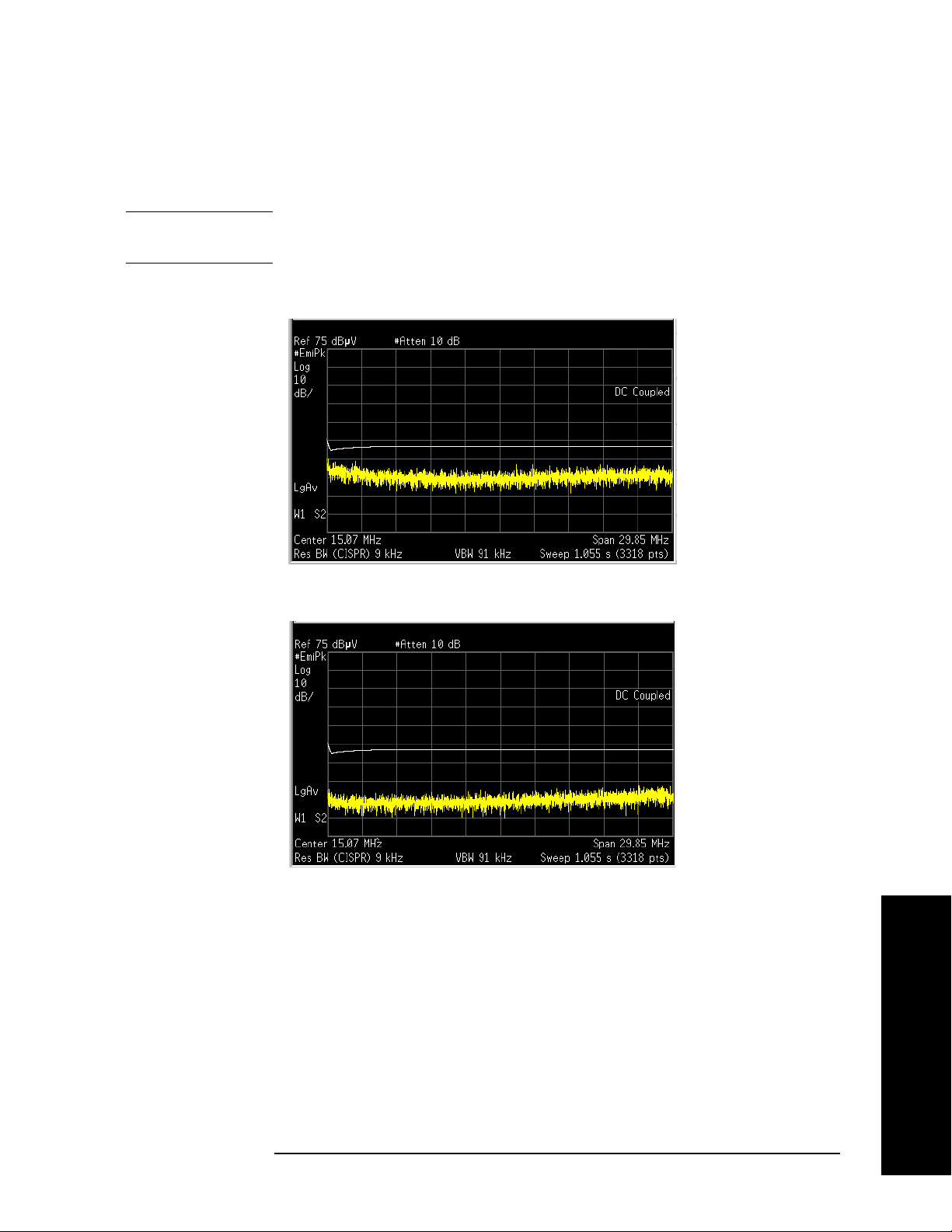
If the noise floor is less than 10 dB below the limit line, toggle
Gain
to On to improve the noise floor versus limit line.
NOTE RF Presel Gain is unavailable (grayed-out) when Use RF Presel is set to
No, or Presel Path is set to Bypass.
RF Presel
Figure 2-10 RF Presel Gain Off
Figure 2-11 RF Presel Gain On
Step 11. On the PSA screen, the PASS/FAIL indicator will show “PASS LIMIT1”
in green color when the peak value of all signals present are below the
regulatory limit, or “FAIL LIMIT1” in red color when the signal exceeds
the limit being used.
Chapter 2 37
Making Measurements
Page 38

Making Measurements
Making Measurements
Figure 2-12 PASS Indicator
Figure 2-13 FAIL Indicator
Making Measurements
Step 12. To analyze signals further, press
windows:
• The upper window is the previous full-screen window, displaying a
full-trace.
• The lower window displays a portion of the trace.
38 Chapter 2
Zoom to split the screen to show two
Page 39

Figure 2-14 Zoomed Screen
Making Measurements
Making Measurements
Step 13. Press
Next Window to toggle to the lower window. The green outlined
window is the active window.
Figure 2-15 Next Window
Step 14. Press
Center Frequency to set the desired center frequency in the lower
window. The value of the center frequency will be automatically coupled
according to the data trace captured.
When you change the center frequency in the lower window, a vertical
positioning indicator in the upper window will move accordingly.
Step 15. Press
displayed data points in the lower window will be changed accordingly.
Around the selected frequency, a minimum of 11 data points and a
maximum of 462 data points will be displayed.
Step 16. Press
detectors to be used to further analyze signals of interest.
Toggle
Toggle
Chapter 2 39
SPAN X Scale, Span to change the span. The number of the
Making Measurements
Meas Setup, Meas at Mkr Detector, you can select or remove the
Quasi Peak to On or Off.
EMI Average to On or Off.
Page 40

Making Measurements
Making Measurements
Figure 2-16 Removing the Quasi Peak and EMI Average Detectors
Figure 2-17 Selecting the Detectors
Step 17. To adjust the measurement dwell time, press
and set the desired time.
Step 18. To analyze individual signals, place a marker on the signal of interest
and press
Marker Fctn, Measure at Marker to perform a measurement of
that signal.
Figure 2-18 Measure at Marker Results
For more information about using the Marker functionality, see the
PSA User's and Programmer's Reference.
Step 19. Repeat the measurement procedure until all of the signals greater than
or equal to the limit line have been measured and record the
measurement results.
Meas Setup, Dwell Time
Making Measurements
40 Chapter 2
Page 41

Radiated Emissions Measurements
Step 1. Complete the system connections, system configuration and system
alignment. See “Connecting the System” on page 22, “Configuring the
System” on page 25 and “Aligning the System” on page 27.
Figure 2-19 Radiated Measurement System Example
Making Measurements
Making Measurements
Step 2. Connect the EUT to the EMI Receiver system using the appropriate
accessories and antenna, as shown in “Radiated Measurement System
Example” on page 41.
Step 3. Press
Step 4. Press
Step 5. Press
NOTE The Presel Path key is unavailable (grayed-out) when Use RF Presel is
set to
Before you switch to
Mode, EMC Analyzer to select the desired mode.
Mode Setup and toggle Use RF Presel to Yes .
Input/Output, Presel Path to ensure the Filter path is selected.
No.
Spectrum Analysis mode, make sure Presel Path is
set to Bypass.
Step 6. Press
CISPR D 300 MHz to 1 GHz.
Mode Setup, EMI Presets, and select the desired band, such as
Step 7. Turn on the EUT power and sweep the frequency range of interest.
Step 8. If you get a message of “RF Presel input is overloaded”, press
Presel Att
NOTE This key is unavailable (grayed-out) when Use RF Presel is set to No, or
Presel Path is set to Bypass.
to increase the attenuation of the RF Preselector.
RF
Making Measurements
Chapter 2 41
Page 42

Making Measurements
Making Measurements
When you change the attenuation setting on the RF Preselector, the
PSA reference level display may change accordingly.
When
Presel Path is set to Filter, the system attenuation only includes
the RF Preselector attenuator although the PSA has a 10 dB fixed
attenuation.
When
Presel Path is set to Bypass, the system attenuation is what you
set on the PSA.
Step 9. To load limit lines for the most common standards, as well as typical
correction factors for a wide variety of measurement transducers, insert
the provided floppy disk of Limit Lines and Transducer Factors into the
floppy disk drive on the PSA and load the desired files for your test. For
more information, see “File Operation” on page 44 and Appendix A ,
“Disk Contents: Limit Lines and Transducer Factors,” on page 101.
• Select
• Select
Limits as the type for loading the Limit Lines files.
Corrections as the type for loading the Transducer Factors
files.
NOTE After loading correction factors for antennas, verify that the reference
level unit is set to dBµV/m
Once the limits have been loaded,
to
On and the limit line will be displayed on the screen.
Limit Display will automatically be set
Making Measurements
Step 10. Press
information about using the
Display, Limits, Limit 1, toggle Limit Test to On. For more
Display function, see the PSA User’s and
Programmer’s reference.
Step 11. Switch the power of the EUT off and check the display to ensure the
noise floor is at least 10 dB below the limit line.
If the noise floor is less than 10 dB below the limit line, toggle
Gain
to On to improve the noise floor versus limit line.
NOTE This key is unavailable (grayed-out) when Use RF Presel is set to No, or
Presel Path is set to Bypass.
Step 12. On the PSA screen, the
PAS S/FAIL indicator will show “PASS LIMIT1” in
RF Presel
green color when the peak value of all signals present are below the
regulatory limit, or “FAIL LIMIT1” in red color when a signal exceeds
the limit being used.
42 Chapter 2
Page 43

Making Measurements
Making Measurements
Step 13. To analyze signals further, press Zoom to split the screen to show two
windows:
• The upper window is the previous full-screen window, displaying a
full-trace.
• The lower window displays a portion of the trace.
Step 14. Press
Next Window to toggle to the lower window. The green outlined
window is the active window.
Step 15. Press
Center Frequency to set the desired center frequency in the lower
window. The value of the center frequency will be automatically coupled
according to the data trace captured.
When you change the center frequency in the lower window, a vertical
positioning indicator in the upper window will move accordingly.
Step 16. Press
SPAN X Scale, Span to change the span. The number of the
displayed data points in the lower window will be changed accordingly.
Around the selected frequency, a minimum of 11 data points and a
maximum of 462 data points will be displayed.
Step 17. Press
Meas Setup, Meas at Mkr Detector, you can select or remove the
detectors to be used to further analyze signals of interest.
Toggle
Toggle
Step 18. To adjust the measurement dwell time, press
Quasi Peak to On or Off.
EMI Average to On or Off.
Meas Setup, Dwell Time
and set the desired time.
Step 19. To analyze individual signals, place a marker on the signal of interest
and press
Marker Fctn, Measure at Marker to perform a measurement of
that signal.
For more information about using the Marker functionality, see the
PSA User's and Programmer's Reference.
Step 20. Repeat the measurement procedure until all of the signals greater than
or equal to the limit line have been measured and record the
measurement results.
Chapter 2 43
Making Measurements
Page 44

Making Measurements
File Operation
File Operation
To access the File menu, press the File front-panel key in the EMC
Analyzer
Saving a Setup file
You can save your current analyzer measurement settings to a Setup
file, and load the Setup file the next time you want to repeat the current
measurement.
Step 1. Press File, Save, Type and select Setup as the type to be saved.
mode.
Step 2. Press
Save Now to save the current measurement settings, including
the State, Trace, Limit and Corrections that you set, to a file with a
default name *.SET. The next time you turn on the PSA, you can load
this Setup file to repeat your test.
NOTE Some settings will not be saved in the Setup file, for example, RF
Preselector IP Address and Source IP Address.
To specify the file name, press
select the directory, use the
Name and enter the desired name. To
Dir Up, Dir Select, and Up and Down keys.
Loading a Setup file
Step 1. Press File, Load, Type and select Setup as the type to be loaded.
Step 2. Select the file to be loaded.
Step 3. Press
Load Now to load the setup as the current measurement.
Making Measurements
44 Chapter 2
Page 45

Making Measurements
File Operation
Loading a Limit file from the floppy disk
You can load a desired limit line file and turn on the Limit Test.
Step 1. Insert the provided floppy disk containing Limit Lines for the most
common standards and typical correction factors for a wide variety of
measurement transducers.
Step 2. Press
File, Load, Type and select Limits.
Step 3. Select the desired file on the A: drive.
Step 4. Press
Load Now to load the file into the PSA.
Loading a Corrections file from the floppy disk
You can load a desired Transducer Factor file for antennas and cables
you are using.
Step 1. Insert the provided floppy disk containing Limit Lines and Transducer
Factors.
Step 2. Press
Step 3. Select the desired file on the A: drive.
Step 4. Press
File, Load, Type and select Corrections.
Load Now to load the file into the PSA.
Chapter 2 45
Making Measurements
Page 46

Making Measurements
Interpreting Error Codes
Interpreting Error Codes
During the execution of your measurement you may encounter
problems which generate error codes. The following list of common
errors may be helpful.
If Err is shown in the annunciator bar, press
System, Show Errors to see
the detailed error information.
• Connection with Presel could not be established at the IP
The analyzer cannot communicate with the RF Preselector with the
given IP address. This error is reported when communication with
the RF Preselector times out.
Verify that the RF Preselector is turned on and the Agilent RF
Preselector application is running.
Verify that the LAN connections of the RF Preselector and PSA are
correct.
Check the RF Preselector IP address information on the PSA by
pressing
Mode Setup, Config EMI Receiver, Show Config.
Verify compliance with the instrument requirements,
see“Instrument Requirements” on page 21, then press
Config
, Verify RF Presel Connection. If no error message appears, the
RF Presel
connection has been established.
• RF Presel model is not supported
The model of the RF Preselector is not supported with the current
version of the Option 239 software.
Making Measurements
• Connection with Source could not be established at the IP
The analyzer cannot communicate with the external signal source
with the given IP address. This error is reported when
communication with the external signal source times out.
Verify that the source and PSA are turned on.
Verify that the LAN connections of the source and PSA are correct. If
your source does not have a LAN port, see Figure 2-2 on page 24 for
instructions on how to connect the source, LAN/Gateway, and PSA.
Check the source configuration information by pressing
Config EMI Receiver, Show Config.
Mode Setup,
Verify compliance with instrument requirements, see“Instrument
Requirements” on page 21, then press
Connection
. If no error message appears, the connection has been
Source Config, Verify S ource
established.
46 Chapter 2
Page 47

Making Measurements
Interpreting Error Codes
• Connection with Source could not be established at the
IP/GPIB
The analyzer cannot communicate with the external signal source
with the given IP and GPIB addresses, when the source was
connected through a LAN/GPIB gateway. This error is reported
when communication with the external signal source times out.
Verify that the source is turned on.
Verify that the LAN/GPIB connections of the source, LAN/Gateway
and PSA are correct. See Figure 2-2 on page 24.
Check the source configuration information on the PSA by pressing
Mode Setup, Config EMI Receiver, Show Config.
Verify compliance with instrument requirements, see “Instrument
Requirements” on page 21, then press
Connection
. If no error message appears, connection has been
Source Config, Verify S ource
established.
• Source model is not supported
The model of the signal generator is not supported with the current
version of the Option 239 software.
Replace the signal generator with a supportable model. See
“Instrument Requirements” on page 21 for a list of signal generator
models.
• RF Preselector alignment required, 9 kHz to 1 GHz
Alignment for the conducted and radiated paths in the RF
Preselector needs to be performed.
See “Aligning the System” on page 27 for instructions on how to
perform the needed alignment.
• RF Preselector alignment required, 9 kHz to 30 MHz
Alignment for the conducted path in the RF Preselector needs to be
performed.
If you are making radiated measurements, you can choose to ignore
this message.
If you are making conducted measurements, see “Aligning the
System” on page 27 for instructions on how to perform the conducted
path alignment.
Making Measurements
Chapter 2 47
Page 48

Making Measurements
Interpreting Error Codes
• RF Preselector alignment required, 30 MHz to 1 GHz
Alignment for the radiated path in the RF Preselector needs to be
performed.
If you are making conducted measurements, you can choose to
ignore this message.
If you are making radiated measurements, see “Aligning the
System” on page 27 for instructions on how to perform the radiated
path alignment.
• RF Presel input is overloaded
Increase the RF Preselector attenuation. Press
Attn
and adjust the attenuation accordingly.
Mode Setup, Presel
• RF Preselector alignment terminated by user
Press the
ESC key to terminated the RF Preselector alignment.
See “Aligning the System” on page 27 for instructions on how to
perform the alignment again before making EMI Receiver
measurements.
• RF Preselector alignment failed, 9 KHz to 30 MHz
If you are making radiated measurements, you can choose to ignore
this message.
If you are making conducted measurements, see “Aligning the
System” on page 27 for instructions on how to perform the conducted
path alignment.
• RF Preselector alignment failed, 30 MHz to 1 GHz
If you are making conducted measurements, you can choose to
ignore this message.
If you are making radiated measurements, see “Aligning the
System” on page 27 for instructions on how to perform the radiated
path alignment.
Making Measurements
• Freq crossing of conducted and radiated bands is not
supported
When Preset path is set to Filter, the instrument sweep cannot cross
over both the conducted and radiated bands.
Either select a band by pressing
the preselector path to
48 Chapter 2
Bypass by pressing Input/Output, Presel Path.
Mode Setup, EMI Presets or toggle
Page 49

Making Measurements
Interpreting Error Codes
• RF Preselector changed, new alignment required
The RF Preselector in the system has been changed. A new
alignment for the RF Preselector is needed.
See “Aligning the System” on page 27 for instructions on how to
perform the needed alignment.
• Cal Source Signal missing, check all the connections
The analyzer could not detect an input signal from the calibration
source.
Verify that the source is turned on.
Verify that the cable connections are correct:
— Source RF OUT to the RF Preselector SRC IN
— RF Preselector RF OUT to the PSA RF INPUT.
• Not available when zoomed graph selected
Some key functions are not supported when the lower window of the
zoomed graph is selected.
Making Measurements
Chapter 2 49
Page 50

Making Measurements
Interpreting Error Codes
Making Measurements
50 Chapter 2
Page 51

Front-Panel Key and SCPI Command
Reference
Chapter 3
3 Front-Panel Key and SCPI
Command Reference
This chapter provides detailed descriptions of the front-panel keys and the
associated SCPI commands and screens used to set up and make EMI Receiver
measurements.
51
Page 52

Front-Panel Key and SCPI Command Reference
Instrument Front Panel Highlights
Reference
Front-Panel Key and SCPI Command
3.1 Instrument Front Panel Highlights
The most commonly used function keys on the PSA front panel are located as shown in the
illustrations below. The operation of the keys is briefly explained on the following page. Refer to
your PSA Series User’s Guide for complete details on all keys.
Figure 3-1 Selected PSA Series Front Panel Feature Locations
3.1.1 Selected and PSA Front-Panel Features
1. The On/Off switch toggles the AC Line power between On and Standby. A green LED will light
52
Chapter 3
Page 53

Front-Panel Key and SCPI Command Reference
Instrument Front Panel Highlights
when the instrument is On. When energized in the standby mode, a yellow LED is lit above
the switch.
2. FREQUENCY Channel accesses a key menu to set the analyzer center frequency in units of Hz,
kHz, MHz, or GHz, or by channel number. These parameters apply to all measurements in the
current mode.
3. MODE accesses a key menu to select one of the measurement personalities installed in the
instrument. Each mode is independent from all other modes.
4. Mode Setup accesses a key menu that sets parameters specific to the current mode and can
affect all measurements within that mode.
5. MEASURE accesses a display key menu to initiate one of the various measurements that are
specific to the current mode.
6. Meas Setup accesses the menus of test parameters that are specific to the current
measurement.
7. Restart causes a measurement to start again from the initial process according to the current
measurement setup parameters.
Front-Panel Key and SCPI Command
Reference
8. RF INPUT port: Type N connector for the E4443A, E4445A, and E4440A PSAs. It is a 2.4 mm
connector on the E4446A, E4447A and E4448A PSAs and a 3.5 mm connector on all PSAs with
Opt BAB. The maximum input power level is shown next to the port.
9. The Data Entry keypad is used to enter numeric values. Keypad entries are displayed in the
active function area of the screen and become valid for the current measurement upon
pressing the
10.The Display Menu keys allow you either to activate a feature or to access a more detailed
Enter key or selecting a unit of measurement, depending on the parameter.
sub-menu. An arrow on the right side of a softkey label indicates that the key has a further
selection menu. The active menu key is highlighted, however, grayed-out keys are currently
unavailable for use or only show information. If a menu has multiple pages, succesive pages
are accessed by pressing the
11. Return allows you to exit the current menu and display the previous menu. If you are on the
first page of a mult-page menu (a menu with
that menu.When you activate another measurement, the return list is cleared. The
More key located at the bottom of the menu.
(1 of 3) for example), the Return key will exit from
Return key
will not return you to a previously activated mode, nor will it alter any values you have
entered in previous menus.
12.BNC Audio Input (PSA Option 233 Measuring Receiver only) Provides a 100 kOhm input for
audio measurements. Frequency range is 20 Hz to 250 kHz. The safe input level is 7 Vrms or
20 V DC.
Chapter 3
53
Page 54

Front-Panel Key and SCPI Command Reference
Front-Panel Keys
Reference
Front-Panel Key and SCPI Command
3.2 Front-Panel Keys
NOTE Only front-panel keys affected by selecting the EMC Analyzer mode are described
here. For a complete description of all front-panel keys, see the PSA Series User’s
and Programmer’s Guide.
3.2.1 Center Frequency, Span for lower window
Allows you to access the center frequency setup menu.
3.2.1.1 Center Frequency
Allows you to set the desired frequency for the lower window.
Mode: EMC Analyzer
Key Path:
Remote Command: [:SENSe]:EMI:FREQuency[:CENTer]
Preset: The center frequency of the upper window
FREQUENCY/Channel
[:SENSe]:EMI:FREQuency[:CENTer]?
State Saved: Saved in instrument state.
Min:
Max:
Dependencies/Couplings: When the start frequency, stop frequency, center or span of the upper
Example: :EMI:FREQ 10000.0
a. Min = Start Freq
b. Max = Stop Freq
Dependent on the start freq of upper window
Dependent on the stop freq of upper window
window changes, it results in a new frequency boundary (start Freq, stop
Freq) in the upper window. If the frequency range of the lower window
exceeds the new boundary of the upper window, the center freq of the lower
window is reset to the center Freq of the upper window, span is also reset
to minimum of the 462 pixels and boundary limitation.
:EMI:FREQ?
upper window
upper window
+ Span
- Span
upper window
upper window
/(SweepPoint
/(SweepPoint
a
b
upper window
upper window
- 1) * 5
- 1) * 5
54
Chapter 3
Page 55

3.2.1.2 Span
Allows you to set the span.
Mode: EMC Analyzer
Front-Panel Key and SCPI Command
Front-Panel Key and SCPI Command Reference
Front-Panel Keys
Reference
Key Path:
SPAN/X Scale, Span
Remote Command: [:SENSe]:EMI:FREQuency:SPAN
[:SENSe]:EMI:FREQuency:SPAN?
Preset: VFreq: freq of vertical marker
USpan: span of upper window
USweepPoint: sweep point of upper window
RightDistance(Hz): vertical marker to right boundary in upper window.
LeftDistance(Hz): vertical marker to left boundary in upper window.
Minimal Distance(Hz) = min(RightDistance, LeftDistance)
LSpan: span of lower window
LSpan = min(USpan / USweepPoint * 231, Minimal Distance)*2;
max value of sweep points in lower window is 462.
State Saved: Saved in instrument state.
Min: USpan/USweepPoint * 10
Max: min Of (USpan/USweepPoint*461, Minimal Distance)
Dependencies/Couplings: When the start frequency, stop frequency, center or span of the upper
window changes, it results in a new frequency boundary (start Freq, stop
Freq) in the upper window. If the frequency range of the lower window
exceeds the new boundary of the upper window, the center freq of the lower
window is reset to the center Freq of the upper window, span is also reset
to minimum of the 462 pixels and boundary limitation.
Example: :EMI:FREQ:SPAN 10000.0
:EMI:FREQ:SPAN?
Chapter 3
55
Page 56

Front-Panel Key and SCPI Command Reference
Front-Panel Keys
3.2.2 File
Reference
Front-Panel Key and SCPI Command
The setup file is a complete set of instrument parameters including traces, states, limits, and
corrections.
3.2.2.1 Save Setup
Saves a setup file to the floppy (A:) or internal (C:) drive.
Mode: EMC Analyzer
Key Path:
Remote Command: :MMEMory:STORe:SETup <‘file_name’>
Dependencies/Couplings: None.
Example: :MMEM:STOR:SET ‘C:\SETUP001.SET’
File, Save
3.2.2.2 Load Setup
Load the setup information from a setup file.
Mode: EMC Analyzer
Key Path:
File, Load
Remote Command: :MMEMory:LOAD:SETup <‘file_name’>
Dependencies/Couplings: None.
Example: :MMEM:LOAD:SET ‘C:\SETUP001.SET’
56
Chapter 3
Page 57

Front-Panel Key and SCPI Command Reference
3.2.3 Input/ Output
PSA Option 239 adds new functions to the existing PSA Input/Output menu.
3.2.3.1 RF Pesel Path
Allows you to select the RF path of the RF Preselector.
Mode: EMC Analyzer
Front-Panel Key and SCPI Command
Front-Panel Keys
Reference
Key Path:
Remote Command: :INPut:PRESelector[:EXTernal]:PATH FILTer|BYPass
Preset: Bypass
State Saved: Saved in instrument state.
Dependencies/Couplings: The PSA sends [:SENSe]:FEED:PATH BYPass|FILTer to the RF
Example: :INP:PRES:PATH FILT
Input/Output, Presel Path
:INPut:PRESelector[:EXTernal]:PATH?
Preselector to set its path
:INP:PRES:PATH?
3.2.3.2 RF Pesel Input
Allows you to select the RF Preselector input.
Mode: EMC Analyzer
Key Path:
Remote Command: :INPut:PRESelector[:EXTernal] RF|SOURce
Input/Output, Presel Input
:INPut:PRESelector[:EXTernal]?
Preset: RF
State Saved: Saved in instrument state.
Dependencies/Couplings: The PSA sends [:SENSe]:FEED RF|SOURce to the RF Preselector to set
the input path.
Example: :INP:PRES RF
:INP:PRES?
Chapter 3
57
Page 58

Front-Panel Key and SCPI Command Reference
Front-Panel Keys
3.2.4 Marker Function
Reference
Front-Panel Key and SCPI Command
Displays the marker function menu for the Emissions measurement when the Marker Fctn key has
been pressed. A new key function, Measure at Marker, is added to the menu.
3.2.4.1 Measure at Marker
Allows you to activate the Measure at Marker function.
Mode: EMC Analyzer
Key Path:
Remote Command: :MEASure:EMI:MARKer
Remote Command Notes: The size of the returned results array is fixed at 4.
Restriction and Notes: This query command returns comma separated values for the Peak
Marker Fctn, Measure at Marker
:MEASure:EMI:MARKer[1]|2|3|4?
•EMI peak value
• EMI QP value
• EMI Average value
• Frequency of Marker
Detector, EMI Average Detector, Quasi Peak Detector and the frequency
value of the measured signal. If the Detector is off or if a measurement
has not yet been made, –999.0 will be returned.
:MEAS:EMI:MARK makes a Measure at Marker measurement at the
active marker frequency.
It’s highly recommended to use the :MEAS:EMI:MARK;*OPC?
commands. The *OPC? command returns a one when the measurement is
done.
:MEAS:EMI:MARK2? returns the previously made measurement if it was
made with marker 2 active.
Example: :MEAS:EMI:MARK;*OPC?
:MEAS:EMI:MARK?
58
Chapter 3
Page 59

Front-Panel Key and SCPI Command Reference
Front-Panel Keys
3.2.5 Meas Control
These functions allow you to pause and resume the currently selected measurement and to select
between continuous or single measurements.
3.2.5.1 Restart
Press this key to repeat the current measurement from the beginning, while retaining the current
measurement settings. This is equivalent to the
Key Path: Meas Control
Remote Command: :INITiate:RESTart
Restart front-panel key.
Front-Panel Key and SCPI Command
Reference
Remote Command
Notes:
Example: :INIT:REST
This command is equivalent to sending an :ABORt command
followed by an :INITiate[:IMMediate] command.
3.2.5.2 Measure
Allows you to toggle the measurement state between
This key has a different function than the
MEASURE front panel key. When set to Single, the
Single and Cont (continuous).
measurement will continue until it has reached the specified number of averages set by the
average counter. When set to
Cont, the measurement will run continuously and execute averaging
according to the current average mode, either repeat or exponential.
Key Path
Factory Preset Cont
State Saved Saved in instrument state.
Remote Command :INITiate:CONTinuous OFF|ON
Remote Command
Notes
Meas Control
When the key is set to ON, at the completion of each trigger
cycle, the trigger system immediately initiates another
trigger cycle.
When the key is set to OFF, the trigger system remains in an
“idle” state until CONTinuous is set to ON or an
:INITiate[:IMMediate] command is received. On receiving the
:INITiate[:IMMediate] command, it will go through a single
trigger cycle, and then return to the “idle” state.
The query INIT:CONT? returns 1 or 0. 1 is returned when the
instrument is continuous triggering. 0 is returned when it is
single triggering.
Example :INIT:CONT OFF
Chapter 3
59
Page 60

Front-Panel Key and SCPI Command Reference
Front-Panel Keys
3.2.5.3 Pause/Resume
Reference
Front-Panel Key and SCPI Command
Press this key to pause the current measurement. Once toggled, the label of the
changes to read Resume. The
Resume key, once pressed, continues the active measurement from
Pause key
the point at which it was paused.
Key Path: Meas Control
Remote Command: :INITiate:PAUSe
:INITiate:RESume
Example: :INIT:PAUS
3.2.6 Mode
Accesses a menu that displays the installed personality modes. The minimum set of available
modes is:
• Spectrum Analysis
• EMC Analyzer
This menu will have additional entries if other personalities have been installed, for example
GSM/EDGE Option 202 or cdmaOne Option BAC.
For information related to the operation of the Spectrum Analysis mode refer to the PSA User’s
and Programmer’s Guide.
For information related to the operation of the Basic mode refer to the PSA Basic Mode Guide.
3.2.6.1 Instrument Selection by Name
Allows you to change from the current mode to the EMC Analyzer mode. This has the same affect
as pressing the
Key Path:
Remote Command: :INSTrument[:SELect] SA|EMC
Preset: SA
Example: INST EMC
EMC Analyzer key.
MODE, EMC Analyzer
:INSTrument[:SELect]?
INST?
60
Chapter 3
Page 61

Front-Panel Key and SCPI Command Reference
Front-Panel Keys
3.2.6.2 Instrument Selection by Number (Remote command only)
This remote command allows you to change from the current mode to EMC Analyzer mode
(Option 239). This has the same effect as pressing the
Remote Command: :INSTrument:NSELect 239
:INSTrument:NSELect?
Example: INST:NSEL 239
INST:NSEL?
EMC Analyzer key.
3.2.7 Mode Setup
Accesses all menus that enable you to change parameters for the available measurements.
3.2.7.1 EMI Presets
Allows you to select the desired EMI CISPR Band
Front-Panel Key and SCPI Command
Reference
Mode: EMC Analyzer
Key Path:
Remote Command: [:SENSe]:FREQuency:PRESelector[:EXTernal]:PBANd
Preset: Upper
State Saved: Saved in instrument state.
Dependencies/Couplings: Selecting these bands will automatically set up RBW, Start/ Stop Freq,
Example: :FREQ:PRES:PBAN A
Mode Setup, EMI Presets
A|B|C|D|CD|E|UPPer
[:SENSe]:FREQuency:PRESelector[:EXTernal]:PBANd?
Trace Points, EMI Peak Detector, units in dBµV and so on for CISPR
measurement. See Table 2-4, “The default values when the EMI Presets
key is pressed for a full-compliance measurement,” on page 34
:FREQ:PRES:PBAN?
Chapter 3
61
Page 62

Front-Panel Key and SCPI Command Reference
Front-Panel Keys
3.2.7.2 Use RF Preselector
Reference
Front-Panel Key and SCPI Command
Selects whether the RF Preselector is used or not.
Mode: EMC Analyzer
Key Path:
Remote Command: [:SENSe]:POWer[:RF]:PRESelector[:EXTernal]:USE YES|NO
State Saved: Saved in instrument state.
Range: Yes | No
Example: :POW:PRES:USE NO
Mode Setup, Use RF Presel
[:SENSe]:POWer[:RF]:PRESelector[:EXTernal]:USE?
:POW:PRES:USE?
3.2.7.3 RF Presel Attenuator
Changes the RF Preselector attenuator setting.
Mode: EMC Analyzer
Key Path:
Remote Command: [:SENSe]:POWer[:RF]:PRESelector[:EXTernal]:ATTenuation
Mode Setup, RF Presel Att
<numeric value>
[:SENSe]:POWer[:RF]:PRESelector[:EXTernal]:ATTenuation?
Preset: 10
State Saved: Saved in instrument state.
Min: 0
Max: 57.5 dB
Dependencies/Couplings: The PSA sends [:SENSe]:POWer[:RF]:ATTenuation <numeric> to the RF
Preselector when you change this setting. The parameter is disabled when
usePresel = No or usePresel =Yes, in bypass mode.
If Presel Atten is set to less than 10 dB, it will be coupled to 10.0 dB,
unless it is 0 dB, it is still set to 0 dB.
Example: :POW:PRES:ATT 10
:POW:PRES:ATT?
62
Chapter 3
Page 63

3.2.7.4 RF Presel Gain
Turns the RF Preselector Gain on and off.
Mode: EMC Analyzer
Front-Panel Key and SCPI Command
Front-Panel Key and SCPI Command Reference
Front-Panel Keys
Reference
Key Path:
Remote Command: [:SENSe]:POWer[:RF]:PRESelector[:EXTernal]:GAIN[:STATe]
Preset: Off
State Saved: Saved in instrument state.
Dependencies/Couplings: The PSA sends [:SENSe]:POWer[:RF]:GAIN[:STATe] ON|OFF|0|1 to the
Example: POW:PRES:GAIN 1
Mode Setup, RF Presel Gain
ON|OFF|0|1
[:SENSe]:POWer[:RF]:PRESelector[:EXTernal]:GAIN[:STATe]?
RF Preselector when you change the setting. The parameter is disabled if
usePresel = No or usePresel =Yes, in bypass mode
POW:PRES:GAIN?
3.2.7.5 EMI Receiver IO Configuration
This menu allows you to configure the IO information of the external RF Preselector and source.
3.2.7.5.1 RF Preselector Configuration
Sets the IO configuration parameters of the RF Preselector.
3.2.7.5.1.1 Preselector IP Address
Sets the IP Address of the RF Preselector to be controlled by the PSA.
Mode: EMC Analyzer
Key Path:
Remote Command: :SYSTem:COMMunicate:LAN:PRESelector[:EXTernal]:IP <string>
State Saved: Persistent, survives a preset and a power cycle but is not saved in the
Example: :SYST:COMM:LAN:PRES:IP 255.255.0.0
Mode Setup, Config EMI Receiver, RF Presel Config
:SYSTem:COMMunicate:LAN:PRESelector[:EXTernal]:IP?
instrument state
:SYST:COMM:LAN:PRES:IP?
Chapter 3
63
Page 64

Front-Panel Key and SCPI Command Reference
Front-Panel Keys
3.2.7.5.1.2 Pre-selector Time Out
Sets the time out value when testing the PSA to the RF Preselector connection.
Reference
Mode: EMC Analyzer
Front-Panel Key and SCPI Command
Key Path:
Mode Setup, Config EMI Receiver, RF Presel Config, Time Out
Remote Command: :SYSTem:COMMunicate:PRESelector:TCONnect:TOUT <time>
:SYSTem:COMMunicate:PRESelector:TCONnect:TOUT?
Min: 1.0s
Max: 120.0s
Example: SYST:COMM:PRES:TCON:TOUT 10
SYST:COMM:PRES:TCON:TOUT?
3.2.7.5.1.3 Verify RF Preselector Connection
Tests the Connection from the PSA to the RF Preselector.
Mode: EMC Analyzer
Key Path:
Mode Setup, Config EMI Receiver, RF Presel Config, Verify RF Presel
Connection
Remote Command: :SYSTem:COMMunicate:PRESelector:TCONnect
:SYSTem:COMMunicate:PRESelector:TCONnect?
Remote Command Notes: The query command returns a zero if the connection has been verified
and returns a one if not.
Example: SYST:COMM:PRES:TCON?
3.2.7.5.1.4 Preselector IDN String (Remote Command Only)
Allows a query of the “*IDN?” string of the external RF Preselector directly from the PSA.
Mode: EMC Analyzer
Remote Command: :SYSTem:COMMunicate:PRESelector:IDN?
Dependencies/Couplings: The PSA sends *IDN to the RF Preselector to query its information.
The parameter is disabled if a connection has not been established at
the specified IP address of the RF Preselector.
Example: :SYST:COMM:PRES:IDN?
64
Chapter 3
Page 65

3.2.7.5.2 Source Config
Sets the IO configuration parameter of the source.
3.2.7.5.2.1 Source Model Number
Selects the model number of the source that the PSA will connect to.
Mode: EMC Analyzer
Front-Panel Key and SCPI Command
Front-Panel Key and SCPI Command Reference
Front-Panel Keys
Reference
Key Path:
Mode Setup, Config EMI Receiver, Source Config, Model Number
Remote Command: :SYSTem:COMMunicate:ESOurce:TYPE
B8648|MXG|N5181A|N5182A|ESG|E4438C|PSG|E8257D
:SYSTem:COMMunicate:ESOurce:TYPE?
Note:
1. :SYSTem:COMMunicate:ESOurce:TYPE MXG is equal to
:SYSTem:COMMunicate:ESOurce:TYPE N5181A.
2. After sending :SYSTem:COMMunicate:ESOurce:TYPE N5181A,
sending :SYSTem:COMMunicate:ESOurce:TYPE? to query, may
return MXG instead of N5181A.
3. :SYSTem:COMMunicate:ESOurce:TYPE ESG is equal to
:SYSTem:COMMunicate:ESOurce:TYPE E4438C.
4. After sending :SYSTem:COMMunicate:ESOurce:TYPE E4438C,
sending :SYSTem:COMMunicate:ESOurce:TYPE? to query, may
return ESG instead of E4438C.
5. :SYSTem:COMMunicate:ESOurce:TYPE PSG is equal to
:SYSTem:COMMunicate:ESOurce:TYPE E8257D.
6. After sending :SYSTem:COMMunicate:ESOurce:TYPE E8257D,
sending :SYSTem:COMMunicate:ESOurce:TYPE? to query, may
return PSG instead of E8257D.
Preset B8648
State Saved: Saved in instrument state.
Dependencies/Couplings: When the 8648B is selected, the connection mode is set to LAN/GPIB
Gateway and conn Mode will be unavailable (greyed out).
When the connection mode is set to LAN, the GPIB Address and Logic
Unit will be unavailable (greyed out).
Example: :SYST:COMM:ESO:TYPE B8648
:SYST:COMM:ESO:TYPE?
Chapter 3
65
Page 66

Front-Panel Key and SCPI Command Reference
Front-Panel Keys
3.2.7.5.2.2 Source Connection Mode
Sets how the PSA is connected with the source.
Reference
Mode: EMC Analyzer
Front-Panel Key and SCPI Command
Key Path:
Mode Setup, Config EMI Receiver, Source Config, Conn Mode
Remote Command: :SYSTem:COMMunicate:ESOurce:CONNection LAN|LG
:SYSTem:COMMunicate:ESOurce:CONNection?
Preset: LAN
State Saved: Saved in instrument state.
Example: :SYST:COMM:ESO:CONN LAN
:SYST:COMM:ESO:CONN?
3.2.7.5.2.3 Source IP Address
Sets the IP Address of the source to be controlled by the RF Preselector during system alignment.
Mode: EMC Analyzer
Key Path:
Mode Setup, Config EMI Receiver, Source Config, IP Address
Remote Command: :SYSTem:COMMunicate:LAN:ESOurce[:EXTernal]:IP <string>
:SYSTem:COMMunicate:LAN:ESOurce[:EXTernal]:IP?
State Saved: Persistent, survives a preset and a power cycle but is not saved in the
instrument state.
Example: :SYST:COMM:LAN:ESO:IP 255.255.0.1
:SYST:COMM:LAN:ESO:IP?
3.2.7.5.2.4 Source GPIB Address
Sets the GPIB address of the source.
Mode: EMC Analyzer
Key Path:
Mode Setup, Config EMI Receiver, Source Config, GPIB Address
Remote Command: :SYSTem:COMMunicate:GPIB:ESOurce[:EXTernal]:ADDRess
<integer>
:SYSTem:COMMunicate:GPIB:ESOurce[:EXTernal]:ADDRess?
State Saved: Persistent, survives a preset and a power cycle but is not saved in the
instrument state.
Example: :SYST:COMM:GPIB:ESO:ADDR 19
:SYST:COMM:GPIB:ESO:ADDR?
66
Chapter 3
Page 67

3.2.7.5.2.5 Source Logical Unit
Sets the Logical Unit of the source.
Mode: EMC Analyzer
Front-Panel Key and SCPI Command
Front-Panel Key and SCPI Command Reference
Front-Panel Keys
Reference
Key Path:
Mode Setup, Config EMI Receiver, Source Config, Logic Unit
Remote Command: :SYSTem:COMMunicate:GPIB:ESOurce[:EXTernal]:LUNit
<integer>
:SYSTem:COMMunicate:GPIB:ESOurce[:EXTernal]:LUNit?
State Saved: Persistent, survives a preset and a power cycle but is not saved in the
instrument state.
Dependencies/Couplings: Set according to the coupling in the Model number.
Preset: 7
Min: 0
Max: 99
Example: :SYST:COMM:GPIB:ESO:LUNit 7
:SYST:COMM:GPIB:ESO:LUNit?
3.2.7.5.2.6 Source Time Out
Sets the time out value when testing the PSA to the source connection.
Mode: EMC Analyzer
Key Path:
Mode Setup, Config EMI Receiver, Source Config, Time Out
Remote Command: :SYSTem:COMMunicate:ESOurce:TCONnect:TOUT <time>
:SYSTem:COMMunicate:ESOurce:TCONnect:TOUT?
Min: 1.0s
Max: 120.0s
Example: SYST:COMM:ESO:TCON:TOUT 10
SYST:COMM:ESO:TCON:TOUT?
Chapter 3
67
Page 68

Front-Panel Key and SCPI Command Reference
Front-Panel Keys
3.2.7.5.2.7 Verify Source Connection
Tests the connection from the PSA to the source.
Reference
Mode: EMC Analyzer
Front-Panel Key and SCPI Command
Key Path:
Remote Command: :SYSTem:COMMunicate:ESOurce:TCONnect
Remote Command Notes: The query command returns a zero if the connection has been verified
Example: SYST:COMM:ESO:TCON?
3.2.7.5.2.8 Source IDN String (Remote Command Only)
Allows a query of the “*IDN?” string of the external source directly from the PSA.
Mode: EMC Analyzer
Remote Command: :SYSTem:COMMunicate:ESOure:IDN?
Example: :SYST:COMM:ESO:IDN?
Mode Setup, Config EMI Receiver, Source Config, Verify Source Connection
:SYSTem:COMMunicate:ESOurce:TCONnect?
and returns a one if not.
3.2.7.5.3 Show Config
Displays a form showing the current configuration information of the RF Preselector and the
source at the specified IP Addresses.
Mode: EMC Analyzer
Key Path:
Dependencies/Couplings: If the source or the RF Preselector cannot be connected successfully, the
Remote Command Notes: Front panel access only.
Mode Setup, Config EMI Receiver, Show Config
corresponding items will be blank.
3.2.7.5.4 Hardware Connection Instruction
Displays a screen showing how to set up the connections of the whole EMI receiver system in
preparation for alignment.
Mode: EMC Analyzer
Key Path:
Remote Command Notes: Front panel access only.
Mode Setup, Config EMI Receive, HW Connection Instruction
68
Chapter 3
Page 69

Front-Panel Key and SCPI Command Reference
Front-Panel Keys
3.2.7.6 Align EMI Preselector
Allows you to initiate the alignment of the RF Preselector. You can choose to align the conducted
(9 kHz to 30 MHz) or the radiated (30 MHz to 1 GHz) paths separately, or both at one time.
3.2.7.6.1 Align 9 kHz to 30 MHz
Aligns the conducted path (9 kHz to 30 MHz) of the RF Preselector.
Mode: EMC Analyzer
Front-Panel Key and SCPI Command
Reference
Key Path:
Remote Command: :CALibration:PRESelector:EXTernal:AB
Remote Command Notes: The query command returns a zero if the alignment is successful and
Example: :CAL:PRES:EXT:AB;*OPC?
Mode Setup, Align RF Presel, Align 9 kHz to 30 MHz
:CALibration:PRESelector:EXTernal:AB[:STATe]?
returns a one if any part of the alignment fails.
It is highly recommended to use the :CAL:PRES:EXT:AB;*OPC?
commands. The *OPC? command returns a one when the alignment is
done.
:CAL:PRES:EXT:AB?
3.2.7.6.2 Align 30 MHz to 1 GHz
Aligns the radiated path (30 MHz to 1 GHz) of the RF Preselector.
Mode: EMC Analyzer
Key Path:
Remote Command: :CALibration:PRESelector:EXTernal:CD
Mode Setup, Align RF Presel, Align 30 MHz to 1 GHz
:CALibration:PRESelector:EXTernal:CD[:STATe]?
Remote Command Notes: The query command returns a zero if the alignment is successful and
returns a one if any part of the alignment fails.
It is highly recommended to use the :CAL:PRES:EXT:CD;*OPC?
commands. The *OPC? command returns a one when the alignment is
done.
Example: :CAL:PRES:EXT:CD;*OPC?
:CAL:PRES:EXT:CD?
Chapter 3
69
Page 70

Front-Panel Key and SCPI Command Reference
Front-Panel Keys
3.2.7.6.3 Align 9 kHz to 1 GHz
Reference
Front-Panel Key and SCPI Command
Aligns both the conducted (9 kHz to 30 MHz) and the radiated (30 MHz to 1 GHz) paths of the RF
Preselector.
Mode: EMC Analyzer
Key Path:
Remote Command: :CALibration:PRESelector:EXTernal:ALL
Remote Command Notes: The query command returns a zero if the alignment is successful and
Example: :CAL:PRESEL:EXT:ALL;*OPC?
Mode Setup, Align RF Presel, Align 9 kHz to 1 GHz
:CALibration:PRESelector:EXTernal:ALL[:STATe]?
returns a one if any part of the alignment fails.
It is highly recommended to use the :CAL:PRESEL:EXT:ALL;*OPC?
commands. The *OPC? command returns a one when the alignment is
done.
:CAL:PRESEL:EXT:ALL?
3.2.7.6.4 Restore Pre-selector Align Default
Loads the default calibration values to the RF Preselector.
Mode: EMC Analyzer
Key Path:
Remote Command: :CALibration:PRESelector:EXTernal:DEFault
Dependencies/Couplings: The PSA sends :CALibration:DATA:DEFault to Preselector.
Example: :CAL:PRES:EXT:DEF;*OPC?
Mode Setup, Align RF Presel, Restore Presel Align Default
It is highly recommended to use the :CAL:PRES:EXT:DEF;*OPC?
commands. The *OPC? command returns a one when the alignment is
done.
3.2.8 System
The PSA Option 239 adds new commands to the existing PSA system function and changes some
existing PSA commands to work with the RF Preselector as an EMI Receiver system.
3.2.8.1 Show Error
The errors generated during the EMI Receiver system alignment and measurement are shown in
the error History. Clear Error Queue will clear the PSA and the RF Preselector Errors queue if
errors exist.
70
Chapter 3
Page 71

Front-Panel Key and SCPI Command Reference
3.3 Measure
Accesses the Measure menus.
3.3.1 Command Interactions: MEASure, CONFigure, FETCh, INITiate and READ
Figure 1 Measurement Group of Commands
Front-Panel Key and SCPI Command
Measure
Reference
Chapter 3
71
Page 72

Front-Panel Key and SCPI Command Reference
Measure
Reference
Front-Panel Key and SCPI Command
Measure Commands:
:MEASure:<measurement>[n]?
This is a fast single-command way to make a measurement using the factory default
instrument settings. These are the settings and units that conform to the Mode Setup
settings (e.g. radio standard) that you have currently selected.
• Stops the current measurement (if any) and sets up the instrument for the specified
measurement using the factory defaults
• Initiates the data acquisition for the measurement
• Blocks other SCPI communication, waiting until the measurement is complete before
returning results.
• After the data is valid it returns the scalar results, or the trace data, for the specified
measurement. The type of data returned may be defined by an [n] value that is sent with the
command.
The scalar measurement results will be returned if the optional [n] value is not included, or is
set to 1. If the [n] value is set to a value other than 1, the selected trace data results will be
returned. See each command for details of what types of scalar results or trace data results
are available.
ASCII is the default format for the data output. The binary data formats should be used for
handling large blocks of data since they are smaller and faster than the ASCII format. Refer
to the FORMat:DATA command for more information.
If you need to change some of the measurement parameters from the factory default
settings you can set up the measurement with the CONFigure command. Use the
commands in the SENSe:<measurement> and CALCulate:<measurement> subsystems
to change the settings. Then you can use the READ? command to initiate the
measurement and query the results. See
Figure 1.
If you need to repeatedly make a given measurement with settings other than the
factory defaults, you can use the commands in the SENSe:<measurement> and
CALCulate:<measurement> subsystems to set up the measurement. Then use the
READ? command to initiate the measurement and query results.
Measurement settings persist if you initiate a different measurement and then return to
a previous one. Use READ:<measurement>? if you want to use those persistent settings.
If you want to go back to the default settings, use MEASure:<measurement>?.
Configure Commands:
:CONFigure:<measurement>
This command stops the current measurement (if any) and sets up the instrument for the
specified measurement using the factory default instrument settings. It sets the instrument to
single measurement mode but should not initiate the taking of measurement data unless
INIT:CONTinuous is ON. After you change any measurement settings, the READ command can
be used to initiate a measurement without changing the settings back to their defaults.
The CONFigure? query returns the current measurement name.
72
Chapter 3
Page 73

Front-Panel Key and SCPI Command Reference
Measure
Fetch Commands:
:FETCh:<measurement>[n]?
This command puts selected data from the most recent measurement into the output buffer. Use
FETCh if you have already made a good measurement and you want to return several types of
data (different [n] values, e.g. both scalars and trace data) from a single measurement. FETCh
saves you the time of re-making the measurement. You can only FETCh results from the
measurement that is currently active, it will not change to a different measurement.
If you need to get new measurement data, use the READ command, which is equivalent to an
INITiate followed by a FETCh.
The scalar measurement results will be returned if the optional [n] value is not included, or is set
to 1. If the [n] value is set to a value other than 1, the selected trace data results will be returned.
See each command for details of what types of scalar results or trace data results are available.
The binary data formats should be used for handling large blocks of data since they are smaller
and transfer faster then the ASCII format. (FORMat:DATA)
FETCh may be used to return results other than those specified with the original READ
or MEASure command that you sent.
Front-Panel Key and SCPI Command
Reference
INITiate Commands:
:INITiate:<measurement>
This command is not available for measurements in all the instrument modes:
• Initiates a trigger cycle for the specified measurement, but does not output any data. You
must then use the FETCh<meas> command to return data. If a measurement other than the
current one is specified, the instrument will switch to that measurement and then initiate it.
For example, suppose you have previously initiated the ACP measurement, but now you are
running the channel power measurement. If you send INIT:ACP? it will change from channel
power to ACP and will initiate an ACP measurement.
• Does not change any of the measurement settings. For example, if you have previously
started the ACP measurement and you send INIT:ACP? it will initiate a new ACP
measurement using the same instrument settings as the last time ACP was run.
• If your selected measurement is currently active (in the idle state) it triggers the
measurement, assuming the trigger conditions are met. Then it completes one trigger
cycle. Depending upon the measurement and the number of averages, there may be
multiple data acquisitions, with multiple trigger events, for one full trigger cycle. It
also holds off additional commands on GPIB until the acquisition is complete.
Chapter 3
73
Page 74

Front-Panel Key and SCPI Command Reference
Measure
READ Commands:
Reference
Front-Panel Key and SCPI Command
:READ:<measurement>[n]?
• Does not preset the measurement to the factory default settings. For example, if you have
previously initiated the ACP measurement and you send READ:ACP? it will initiate a new
measurement using the same instrument settings.
• Initiates the measurement and puts valid data into the output buffer. If a measurement other
than the current one is specified, the instrument will switch to that measurement before it
initiates the measurement and returns results.
For example, suppose you have previously initiated the ACP measurement, but now you are
running the channel power measurement. Then you send READ:ACP? It will change from
channel power back to ACP and, using the previous ACP settings, will initiate the
measurement and return results.
• Blocks other SCPI communication, waiting until the measurement is complete before
returning the results
If the optional [n] value is not included, or is set to 1, the scalar measurement results
will be returned. If the [n] value is set to a value other than 1, the selected trace data
results will be returned. See each command for details of what types of scalar results
or trace data results are available. The binary data formats should be used when
handling large blocks of data since they are smaller and faster then the ASCII
format. (FORMat:DATA)
3.3.2 Emissions
Allows you to switch to the Emissions measurement.
Mode: EMC Analyzer
Key Path:
Remote Command: See “Remote SCPI Result - SCPI Only Commands” on page
MEASURE
74
Table 3-1 Remote SCPI Result - SCPI Only Commands
Command Index: n
<Mnemonic>
:CONFigure:EMI N/A Not Applicable
:INITiate:EMI N/A Not Applicable
:FETCh:EMI[n]? 0Swept trace
:MEASure:EMI[n]? 0Swept trace
:READ:EMI[n]? 0Swept trace
Results Returned
74
Chapter 3
Page 75

Front-Panel Key and SCPI Command Reference
Measurement Key
3.4 Measurement Key
The Emissions measurement is currently the only available measurement in the EMC Analyzer
Mode.
3.4.1 Emissions Measurement
When you press the Emissions key you get a full-trace window as a default display. When you
press the front-panel
• Full-Trace window (upper) - same as the default display.
• User-Defined window (lower) - a user-selectable number of points around a vertical marker
line is displayed.
3.4.1.1 Meas Setup
Zoom key, you get a split screen with the following two windows:
Front-Panel Key and SCPI Command
Reference
Displays the measurement setup menu for the Emissions Measurement.
3.4.1.1.1 Quasi Peak Detector
Allows you to turn on or off the Quasi Peak detector for the Measure at Marker function.
Key Path: Meas Setup, Meas at Mkr Detector, Quasi Peak
Mode: EMC Analyzer
Remote Command: [:SENSe]:EMI:MEASure:DETector:QPEak[:STATe] OFF|ON|0|1|
Preset: On
State Saved: Saved in instrument state
Example: :EMI:MEAS:DET:QPE ON
3.4.1.1.2 EMI Average Detector
Allows you to turn on or off the EMI Average Detector for the Measure at Marker function.
Key Path:
Mode: EMC Analyzer
Meas Setup, Meas at Mkr Detector, EMI Average
Remote Command: [:SENSe]:EMI:MEASure:DETector:AVERage[:STATe] OFF|ON|0|1
Preset: On
State Saved: Saved in instrument state
Example: :EMI:MEAS:DET:AVER ON
Chapter 3
75
Page 76

Front-Panel Key and SCPI Command Reference
Measurement Key
3.4.1.1.3 Dwell Time
Reference
Front-Panel Key and SCPI Command
Allows you to setup the detector Dwell Time for the Measure at Marker function.
Mode: EMC Analyzer
Key Path:
Remote Command: [:SENSe]:EMI:MEASure:DETector:DWELl <time>
Preset: 200.0 ms
Min: 4.0 ms
Max: 2000.0 s
State Saved: Saved in instrument state
Example: :EMI:MEAS:DET:DWEL 200ms
Meas Setup, Dwell Time
[:SENSe]:EMI:MEASure:DETector:DWELl?
:EMI:MEAS:DET:DWEL?
76
Chapter 3
Page 77

Menu Maps
4 Menu Maps
These menu maps are in alphabetical order by the front- panel key label or oval
cross-reference label. You can locate detailed information about each key/function at the
page number listed in the figure title for each menu.
77
Page 78

Menu Maps
EMI Measurement Key Flow
EMI Measurement Key Flow
The key flow diagrams, shown in a hierarchical manner on the following pages, explain the
overall functional relationships for the front-panel keys and the softkeys displayed at the
right side of the screen. The diagrams are:
“File Key Flow (1 of 4)” on page 92
“Input/Output Key Flow” on page 80
“Marker Function Key Flow” on page 81
“Measurement Selection Key Flow” on page 82
“Measurement Setup Key Flow” on page 83
“Mode Selection Key flow” on page 84
Menu Maps
“Mode Setup Selection Key Flow (1 of 6)” on page 85
“System Key Flow” on page 91
78 Chapter 4
Page 79
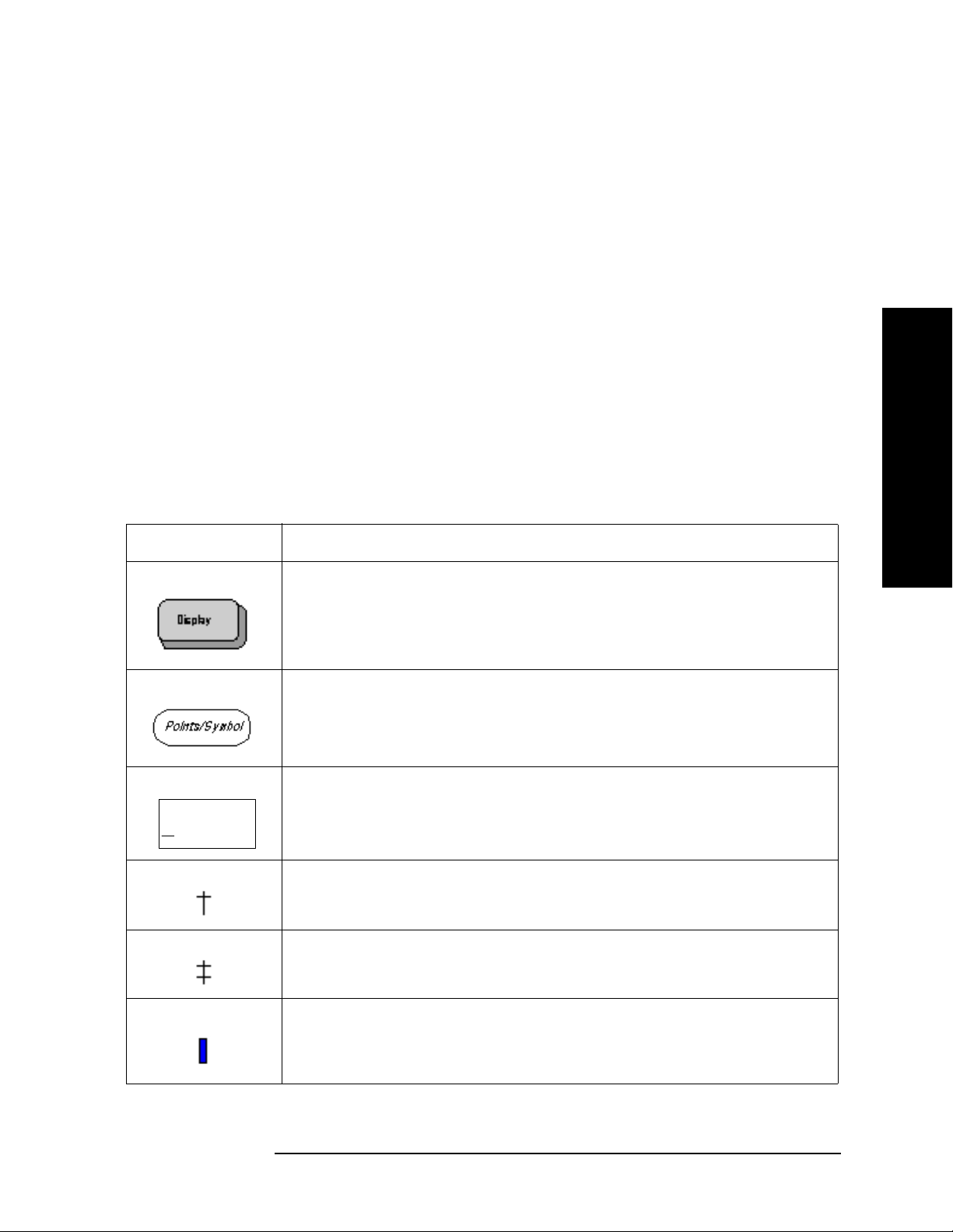
Menu Maps
EMI Measurement Key Flow
Directions for Use
Refer to the following notes to utilize the key-flow diagrams:
• Start from the upper left corner of each measurement diagram. Go to the right, and go
from the top to the bottom.
• When changing a key from auto (with underline) to manual, just press that key one
time.
• When entering a numeric value for Frequency, a value with units, use the numeric
keypad and terminate the entry with the appropriate unit selection from the softkeys
displayed.
• When entering a numeric value for a unitless value, like Avg Number, use the numeric
keypad and terminate the entry with the
• Instead of using the numeric keypad to enter a value, it may be easier to use the
front-panel knob or
Up/Down arrow keys.
Table 4-1 Menu Map Legend
Enter front-panel key.
Menu Maps
Icon Description
This represents the analyzer front-panel key.
An oval represents additional levels of menus.
This box shows how the softkey default condition is displayed.
Default parameters or values are underlined wherever possible.
ADC Dither
On Off
A dagger to the left of a softkey indicates that when the key is pressed this
is an active function.
A double-dagger to the left of the softkey indicates a function that is not
always available. It is dependent on other instrument settings.
A bar on the left of two or more softkeys indicates that the keys are a
mutually exclusive choice.
Chapter 4 79
Page 80

Figure 4-1 Input/Output Key Flow
Input/
Output
Menus
Input/Output Key
Input/Output
Input Port
RF
RF Coupling
AC
DC
321.4 MHz
IF Out
SA
Microwave
Preselector
On Off
Presel Input
RF Source
Presel Path
Filter Bypass
Page 81

Figure 4-2 Marker Function Key Flow
Chapter 4 81
Marker
Menus
Marker Fctn Key
Fctn
Marker Fctn
Select Marker
1
2 3 4
Marker Noise
Band/Intvl
Power
Function Off
Measure at
Marker
Marker Count
EMI Measurement Key Flow
Menu Maps
Menu Maps
Page 82

Figure 4-3 Measurement Selection Key Flow
Menu Maps
82 Chapter 4
MEASURE
Menus
Measure Key
Measure
Emissions
EMI Measurement Key Flow
Menu Maps
Page 83

Figure 4-4 Measurement Setup Key Flow
Chapter 4 83
Meas
Setup
Menus
Meas Setup Key
Meas Setup
Meas at Mkr
Detector
Dwell Time
200.0 ms
Meas Mkr Det
Quasi Peak
On
Off
EMI Average
On
Off
EMI Measurement Key Flow
Menu Maps
Menu Maps
Page 84

Figure 4-5 Mode Selection Key flow
Menu Maps
84 Chapter 4
MODE
Menus
Mode Key
Mode
Spectrum
Analysis
EMC Analyzer
EMI Measurement Key Flow
Menu Maps
Page 85

Chapter 4 85
Figure 4-6 Mode Setup Selection Key Flow (1 of 6)
Mode
Setup
Menus
Mode Setup Key (1 of 6)
Mode Setup
EMI Presets
Use RF Presel
Yes No
RF Presel Atten
10.00 dB
RF Presel Gain
On Off
Config EMI
Receiver
Align RF
Presel
Config EMI
Receiver
Align RF Presel
EMI Presets
CISPR A
9 kHz
to 150 kHz
CISPR B
150 kHz
to 30 MHz
CISPR C
30 MHz
to 300 MHz
CISPR D
300 MHz
to 1 GHz
CISPR C/D
30 MHz
to 1 GHz
CISPR E
1 GHz
to 18 GHz
1 GHz & Above
EMI Measurement Key Flow
Menu Maps
Menu Maps
Page 86

Figure 4-7 Mode Setup Selection Key Flow (2 of 6)
Menu Maps
86 Chapter 4
Config EMI
Receiver
Menus
Mode Setup Key (2 of 6)
Config EMI Presel Config
RF Presel
Config
Source Config
Show Config
HW Connection
Instruction
Show Config
HW Connection
Instruction
Source Config
Model Number
Conn Mode
ٛ
IP Address
GPIB Address
ٛ
Logic Unit
Verify Source
Connection
8648B
LAN
0.0.0.0
19
Time Out
1.0 s
Model Number
8648B
N5181A
IP Address
10.10.10.10
Time Out
N5182A
E4438C
7
E8257D
RF Presel
Connection
Conn Mode
10.00 s
Verify
EMI Measurement Key Flow
Menu Maps
Page 87

Chapter 4 87
Figure 4-8 Mode Setup Selection Key Flow (3 of 6)
Show Config
Menus
Mode Setup Key (3 of 6)
EMI Measurement Key Flow
Menu Maps
Menu Maps
Page 88

Figure 4-9 Mode Setup Selection Key Flow (4 of 6)
Menu Maps
88 Chapter 4
HW Connection Instruction
Menus
Mode Setup Key (4 of 6)
EXTERNAL
TRIGGER OUT
(REAR)
PRE-SELECTOR
TO EUT
PULSE
TRIGGER 2 OUT
(REAR)
LAN
SRC INRF IN
RF
OUT
TRIG IN
(REAR)
RF
IN
TRIG IN
(FRONT)
PSA
LAN RF OUT LAN GPIB
ETHERNET
SWITCH/HUB
10MHz
REF OUT
(REAR)
10MHz
REF IN
(REAR)
SIGNAL
SOURCE
LAN/GPIB
GATEWAY
FOR SOURCE
W/O LAN
EMI Measurement Key Flow
Menu Maps
Page 89

Figure 4-10 Mode Setup Selection Key Flow (5 of 6)
Chapter 4 89
Conn Mode
Menus
Mode Setup Key (5 of 6)
Conn Mode
LAN
LAN/GPIB
Gateway
EMI Measurement Key Flow
Menu Maps
Menu Maps
Page 90

Figure 4-11 Mode Setup Selection Key Flow (6 of 6)
Menu Maps
90 Chapter 4
Align RF Presel
Menus
Mode Setup Key (6 of 6)
Align RF Presel
Align 9 kHz
to 30 MHz
Align 30 MHz
to 1GHz
Align 9 kHz
to 1 GHz
Restore Presel
Align Default
EMI Measurement Key Flow
Menu Maps
Page 91

Figure 4-12 System Key Flow
Chapter 4 91
System
Menus
Show Errors Key
System
Show Errors
Power On/
Preset
Time/Date
Alignments
Config I/O
Reference
More
1 of 3
Show Errors
Prev Page
Next Page
Verbose SCPI
On Off
Clear Error
Queue
Clear Error Queue will clear
the PSA and RF Preselector
errors if there are any.
EMI Measurement Key Flow
Menu Maps
Menu Maps
Page 92
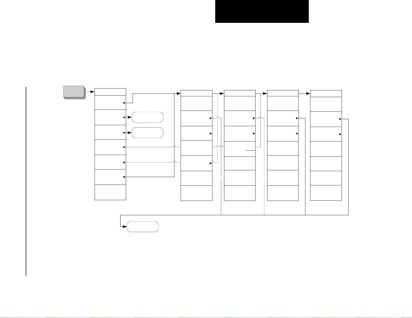
Figure 4-13 File Key Flow (1 of 4)
Menu Maps
92 Chapter 4
File
Menus
File Key (1 of 4)
File
Catalog
Save
Load
Delete
Copy
Rename
More
1 of 2
Save
Load
Type
Rename
Rename Now
Type
State
Sort
Name
Dir Up
Dir Select
Copy
Copy Now
Type
State
Sort
Dir
From
To
Dir Up
Dir Select
Delete
Delete Now
Type
State
Sort
Dir Up
Dir Select
Catalog
Type
State
Sort
Dir Up
Dir Select
EMI Measurement Key Flow
Menu Maps
Page 93

Chapter 4 93
Figure 4-14 File Key Flow (2 of 4)
Load
Menus
File Key (2 of 4)
Load
Load Now
Type
State
Sort
Destination
Dir Up
Dir Select
Type
State
Trace
Limits
Corrections
More
1 of 2
Type
Setup
More
2 of 2
EMI Measurement Key Flow
Menu Maps
Menu Maps
Page 94

Figure 4-15 File Key Flow (3 of 4)
Menu Maps
94 Chapter 4
Save
Menus
File Key (3 of 4)
Save
Save Now
Type
State
Format
Trace + State
Source
All Traces
Name
Dir Up
Dir Select
Type
State
Trace
Limits
Screen
Corrections
More
1 of 2
Type
Setup
Masurement
Results
More
2 of 2
EMI Measurement Key Flow
Menu Maps
Page 95
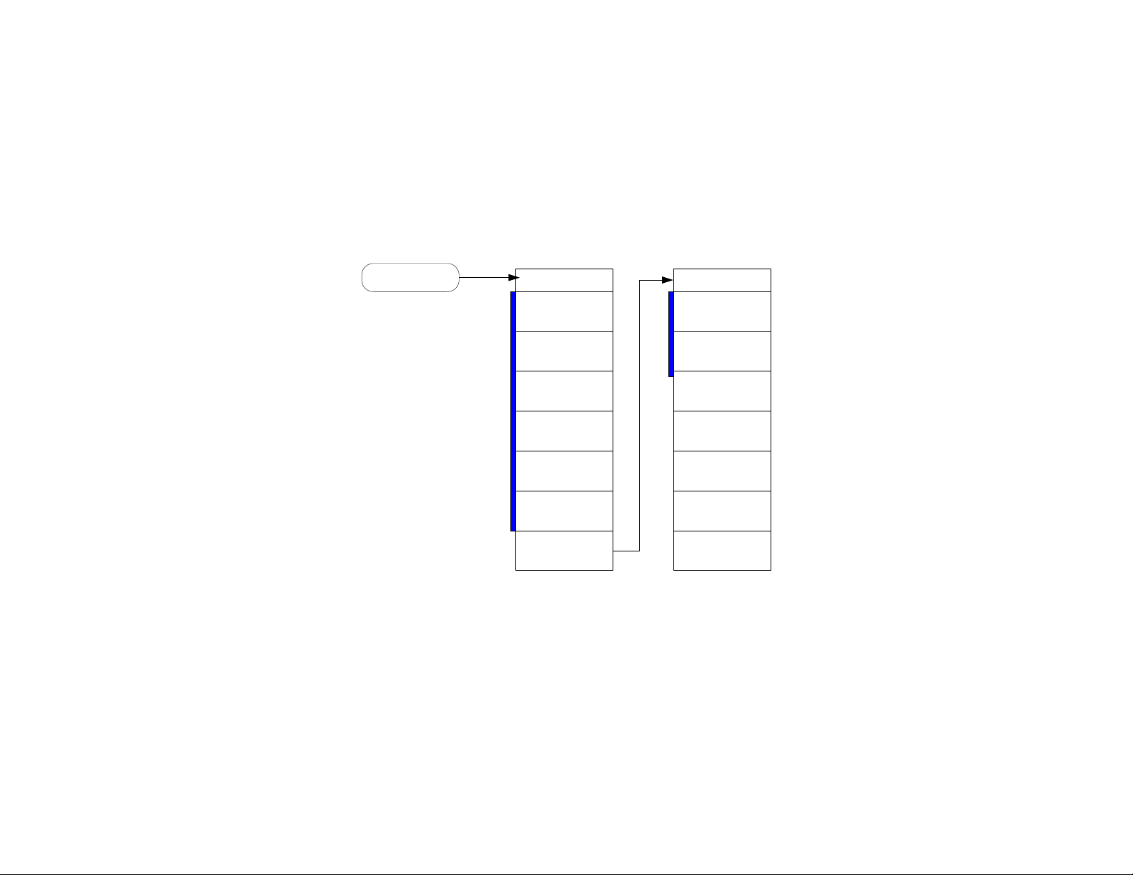
Figure 4-16 File Key Flow (4 of 4)
Type
Menus
File Key (4 of 4)
Type
All
State
Trace
Limits
Screen
Corrections
More
1 of 2
Type
Setup
Masurement
Results
More
2 of 2
Page 96

Menu Maps
Menu Maps
EMI Measurement Key Flow
96 Chapter 4
Page 97

A Disk Contents: Limit Lines and
Transducer Factors
Disk Contents: Limit Lines and
Transducer Factors
97
Page 98

Disk Contents: Limit Lines and Transducer Factors
Limit Line Table
Limit Line Table
Table A-1 Limit Lines
Description Frequency Range DOS Filename
AS/NZS 1044; Conducted Household Appliances,
Quasi-Peak
AS/NZS 1044; Conducted Household Appliances,
Average
AS/NZS 1044; Conducted < 700 W, Motors,
Quasi-Peak
AS/NZS 1044; Conducted < 700 W, Motors, Average 150 kHz to 30 MHz 1044Cx7A.lim
AS/NZS 1044; Conducted > 700 W < 1000 W, Motors,
Quasi-Peak
AS/NZS 1044; Conducted > 700 W < 1000 W, Motors,
Average
AS/NZS 1044; Conducted > 1000 W, Motors,
Quasi-Peak
AS/NZS 1044; Conducted > 1000 W, Motors, Average 150 kHz to 30 MHz 1044C1xA.lim
AS/NZS 1044; Radiated Household Appliances,
Quasi-Peak
AS/NZS 1044; Radiated Household Appliances,
Average
150 kHz to 30 MHz 1044CHAQ.lim
150 kHz to 30 MHz 1044CHAA.lim
150 kHz to 30 MHz 1044Cx7Q.lim
150 kHz to 30 MHz 1044Cx1Q.lim
150 kHz to 30 MHz 1044Cx1A.lim
150 kHz to 30 MHz 1044C1xQ.lim
30 MHz to 300 MHz 1044RHAQ.lim
30 MHz to 300 MHz 1044RHAA.lim
AS/NZS 1044; Radiated < 700 W, Motors, Quasi-Peak 30 MHz to 300 MHz 1044Rx7Q.lim
AS/NZS 1044; Radiated < 700 W, Motors, Average 30 MHz to 300 MHz 1044Rx7A.lim
Transducer Factors
Disk Contents: Limit Lines and
AS/NZS 1044; Radiated > 700 W < 1000 W, Motors,
Quasi-Peak
AS/NZS 1044; Radiated > 700 W < 1000 W, Motors,
Average
AS/NZS 1044; Radiated > 1000 W, Motors,
Quasi-Peak
AS/NZS 1044; Radiated > 1000 W, Motors, Average 30 MHz to 300 MHz 1044R1xA.lim
AS/NZS 2064; Class A Conducted, Group 1, Average 150 kHz to 30 MHz 2064AC1A.lim
AS/NZS 2064; Class A Conducted, Group 1,
Quasi-Peak
AS/NZS 2064; Class A Conducted, Group 2, Average 150 kHz to 30 MHz 2064AC2A.lim
30 MHz to 300 MHz 1044Rx1Q.lim
30 MHz to 300 MHz 1044Rx1A.lim
30 MHz to 300 MHz 1044R1xQ.lim
150 kHz to 30 MHz 2064AC1Q.lim
98 Appendix A
Page 99

Disk Contents: Limit Lines and Transducer Factors
Limit Line Table
Table A-1 Limit Lines (Continued)
Description Frequency Range DOS Filename
AS/NZS 2064; Class A Conducted, Group 2,
150 kHz to 30 MHz 2064AC2Q.lim
Quasi-Peak
AS/NZS 2064; Class B Conducted, Group 1 and 2,
150 kHz to 30 MHz 2064BCQ.lim
Quasi-Peak
AS/NZS 2064; Class B Conducted, Group 1 and 2,
150 kHz to 30 MHz 2064BCA.lim
Average
AS/NZS 2064; Class A Radiated, Group 1 30 MHz to 1 GHz 2064AR1.lim
AS/NZS 2064; Class A Radiated, Group 2 150 kHz to 1 GHz 2064AR2.lim
AS/NZS 2064; Class B Radiated, Group 1 30 MHz to 1 GHz 2064BR1.lim
AS/NZS 2064; Class B Radiated, Group 2 30 MHz to 1 GHz 2064BR2.lim
AS/NZS 3548; Class A Conducted, Quasi-Peak 150 kHz to 30 MHz 548ACQP.lim
AS/NZS 3548; Class A Conducted, Average 150 kHz to 30 MHz 3548ACAV.lim
AS/NZS 3548; Class B Conducted, Quasi-Peak 150 kHz to 30 MHz 3548BCQP.lim
AS/NZS 3548; Class B Conducted, Average 150 kHz to 30 MHz 3548BCAV.lim
AS/NZS 3548; Class A Radiated (10m) 30 MHz to 1 GHz 3548AR10.lim
AS/NZS 3548; Class A Radiated (30m) 30 MHz to 1 GHz 3548AR30.lim
Disk Contents: Limit Lines and
AS/NZS 3548; Class B Radiated (10m) 30 MHz to 1 GHz 3548BR10.lim
BellCore 1089; Conducted, Analog Voiceband Leads
8 kHz to 6 MHz 1089CVBL.lim
(Longitudinal)
BellCore 1089; Conducted, Analog Voiceband Leads
8 kHz to 6 MHz 1089CVBM.lim
(Metallic)
BellCore 1089; Class A Conducted, AC Power Leads
450 kHz to 69.5 MHz 1089CAPQ.lim
(Quasi-Peak)
BellCore 1089; Class A Conducted, AC Power Leads -
450 kHz to 69.5 MHz 1089CAPV.lim
Volt ag e
BellCore 1089; Class B Conducted, AC Power Leads -
450 kHz to 47.9 MHz 1089CBPV.lim
Volt ag e
BellCore 1089; Radiated (3m) - Doors Open 10 kHz to 10 GHz 1089R3DO.lim
BellCore 1089; Radiated (3m) - Doors Closed 10kHz to 10 GHz 1089R3DC.lim
BellCore 1089; Radiated (10m) - Doors Open 10 kHz to 10 GHz 1089R1DO.lim
BellCore 1089; Radiated (10m) - Doors Closed 10 kHz to 10 GHz 1089R1DC.lim
EN 55011; Class A Conducted, Group 1, Quasi-Peak 150 kHz to 30 MHz EN11AC1Q.lim
EN 55011; Class A Conducted, Group 1, Average 150 kHz to 30 MHz EN11AC1A.lim
Transducer Factors
Appendix A 99
Page 100

Disk Contents: Limit Lines and Transducer Factors
Limit Line Table
Table A-1 Limit Lines (Continued)
Description Frequency Range DOS Filename
EN 55011; Class A Conducted, Group 2, Quasi-Peak 150 kHz to 30 MHz EN11AC2Q.lim
EN 55011; Class A Conducted, Group 2, Average 150 kHz to 30 MHz EN11AC2A.lim
EN 55011; Class B Conducted, Group 1 and 2,
150 kHz to 30 MHz EN11BCQ.lim
Quasi-Peak
EN 55011; Class B Conducted, Group 1 and 2,
150 kHz to 30 MHz EN11BCA.lim
Average
EN 55011; Class A Radiated, Group 1 30 MHz to 1 GHz EN11AR1.lim
EN 55011; Class A Radiated, Group 2 150 kHz to 1 GHz EN11AR2.lim
EN 55011; Class B Radiated, Group 1 30 MHz to 1 GHz EN11BR1.lim
EN 55011; Class B Radiated, Group 2 30 MHz to 1 GHz EN11BR2.lim
EN 55014; Conducted Household Appliances,
Quasi-Peak
EN 55014; Conducted Household Appliances,
150 kHz to 30 MHz EN14CHAQ.li
m
150 kHz to 30 MHz EN14CHAA.lim
Average
EN 55014; Conducted < 700 W, Motors, Quasi-Peak 150 kHz to 30 MHz EN14Cx7Q.lim
EN 55014; Conducted < 700 W, Motors, Average 150 kHz to 30 MHz EN14Cx7A.lim
EN 55014; Conducted > 700 W < 1000 W, Motors,
150 kHz to 30 MHz EN14Cx1Q.lim
Quasi-Peak
EN 55014; Conducted > 700 W < 1000 W, Motors,
150 kHz to 30 MHz EN14Cx1A.lim
Average
EN 55014; Conducted > 1000 W, Motors, Quasi-Peak 150 kHz to 30 MHz EN14C1xQ.lim
EN 55014; Conducted > 1000 W, Motors, Average 150 kHz to 30 MHz EN14C1xA.lim
Transducer Factors
EN 55014; Radiated Household Appliances,
Disk Contents: Limit Lines and
Quasi-Peak
EN 55014; Radiated Household Appliances, Average 30 MHz to 300 MHz EN14RHAA.lim
EN 55014; Radiated < 700 W, Motors, Quasi-Peak 30 MHz to 300 MHz EN14Rx7Q.lim
EN 55014; Radiated < 700 W, Motors, Average 30 MHz to 300 MHz EN14Rx7A.lim
EN 55014; Radiated > 700 W < 1000 W, Motors,
Quasi-Peak
EN 55014; Radiated > 700 W < 1000 W, Motors,
Average
EN 55014; Radiated > 1000 W, Motors, Quasi-Peak 30 MHz to 300 MHz EN14R1xQ.lim
EN 55014; Radiated > 1000 W, Motors, Average 30 MHz to 300 MHz EN14R1xA.lim
30 MHz to 300 MHz EN14RHAQ.li
m
30 MHz to 300 MHz EN14Rx1Q.lim
30 MHz to 300 MHz EN14Rx1A.lim
100 Appendix A
 Loading...