

Page 1

HP 8566B/68B Code Compatibility Guide
Agilent Technologies
ESA and PSA Series Spectrum Analyzers
This manual pro vide s docum en tat ion for the follow ing
instruments with Option 266 installed:
ESA-E Series
E4401B (9 kHz - 1.5 GHz)
E4402B (9 kHz - 3.0 GHz)
E4404B (9 kHz - 6.7 GHz)
E4405B (9 kHz - 13.2 GHz)
E4407B (9 kHz - 26.5 GHz)
PSA Series
E4440A (3 Hz - 26.5 GHz)
E4443A (3 Hz - 6.7 GHz)
E4445A (3 Hz - 13.2 GHz)
E4446A (3 Hz - 44.0 GHz)
E4448A (3 Hz - 50.0 GHz)
Manufacturing Part Number: E4440-90223
Supersed es: E4440-90066
Printed in USA
February 2003
© Copyri gh t 2002, 2003 Agilent Technologie s, Inc.
Page 2

Notice
The information contained in this document is subject to change
without notice.
Agilent T echnol ogies makes no w arranty of any kind with re gard to this
material, including but not limited to, the implied warranties of
merchantability and fitness for a particular purpose. Agilent
Technologies shall not be liable for errors contained herein or for
incidental or consequential damages in connection with the furnishing,
performance, or use of this material.
Warranty
This Agilent Technologies instrument product is warranted against
defects in mat erial and wor kmanship for a pe ri o d o f three years from
date of shipment. During the warranty period, Agilent Technologies
Company will, at its option, either repair or replace products that prove
to be defective.
For warranty service or repair, this product must be returned to a
service facility designated by Agilent Technologies. Buyer shall prepay
shipping charges to Agilent Technologies and Agilent Technologies shall
pay shipping charges to return the product to Buyer. However, Buyer
shall pay all shipping charges, duties, and taxes for products returned
to Agilent Technologies from another country.
Agilent Technologi e s warrants that it s so ft ware an d fi rmware
designated by Agilent Technologies for use with an instrument will
execute its programming instructions when properly installed on that
instrument. Agilent T echnolog ies does not warrant that the operation of
the instrument, or software, or firmware will be uninterrupted or
error-free.
2
Page 3

LIMITATION OF WARRANTY
The fore go ing warrant y s h all not apply to de fects result in g from
improper or inadequate maintenance by Buyer, Buyer-supplied
software or inter f acing, unauthorized modifi cation or misuse, oper ation
outside of the environment al spe cif ications for the product, or i mproper
site preparation or maintenance.
NO OTHER WARRANTY IS EXPRESSED OR IMPLIED. AGILENT
TECHNOLOGIES SPECIFICALLY DISCLAIMS THE IMPLIED
WARRANTIES OF MERCHANTABILITY AND FITNESS FOR A
PARTICULAR PURPOSE.
EXCLUSIVE REMEDIES
THE REMEDIES PROVIDED HEREIN ARE BUYER’S SOLE AND
EXCLUSIVE REMEDIES. AGILENT TECHNOLOGIES SHALL NOT
BE LIABLE FOR ANY DIRECT, INDIRECT , SPECIAL, INCID ENTAL,
OR CONSEQUENTIAL DAMAGES, WHETHER BASED ON
CONTRACT, TORT, OR ANY OTHER LEGAL THEORY.
3
Page 4

4
Page 5

Contents
1. Getting Started
Option 266 Description . . . . . . . . . . . . . . . . . . . . . . . . . . . . . . . . . . . . . . . . . . . . . . . . . . . . . . . . 2
Option 266 Limitations . . . . . . . . . . . . . . . . . . . . . . . . . . . . . . . . . . . . . . . . . . . . . . . . . . . . . . 2
Hardware Requirements for Optio n 266 . . . . . . . . . . . . . . . . . . . . . . . . . . . . . . . . . . . . . . . . . . 3
Installing/Unin stalling Option 266 - ESA-E Ser ie s Analy zers Only . . . . . . . . . . . . . . . . . . . . 4
Creating the Installation Disks from the Web . . . . . . . . . . . . . . . . . . . . . . . . . . . . . . . . . . . . 4
Installing the Option 266 So ftware . . . . . . . . . . . . . . . . . . . . . . . . . . . . . . . . . . . . . . . . . . . . . 4
Installer Screen and Menu . . . . . . . . . . . . . . . . . . . . . . . . . . . . . . . . . . . . . . . . . . . . . . . . . . . . . 6
Troubleshooting the Installer . . . . . . . . . . . . . . . . . . . . . . . . . . . . . . . . . . . . . . . . . . . . . . . . . . 8
Installing Option 266 - PSA Se r ies Analyzers Only . . . . . . . . . . . . . . . . . . . . . . . . . . . . . . . . 9
Configuring Option 266 - ESA and PSA Analyzers . . . . . . . . . . . . . . . . . . . . . . . . . . . . . . . . . 12
Analyzer Settings When Changing Language . . . . . . . . . . . . . . . . . . . . . . . . . . . . . . . . . . . . . 14
Analyzer Settings After Powering On and Off . . . . . . . . . . . . . . . . . . . . . . . . . . . . . . . . . . . 14
The Configure Remote Lang Scre en Menu - ESA-E and PSA Analyzers . . . . . . . . . . . . . . . 15
Differences Between Option 266 Commands and the Original HP 8566B/HP 8568B
Commands . . . . . . . . . . . . . . . . . . . . . . . . . . . . . . . . . . . . . . . . . . . . . . . . . . . . . . . . . . . . . . . . . 17
Differences Between HP8566B and HP8568B Remote Languages in Option 266 . . . . . . . . 26
Running Software that Requires SCPI Commands . . . . . . . . . . . . . . . . . . . . . . . . . . . . . . . . 28
Service and Calibration . . . . . . . . . . . . . . . . . . . . . . . . . . . . . . . . . . . . . . . . . . . . . . . . . . . . . . . 30
Documentation for Option 266 . . . . . . . . . . . . . . . . . . . . . . . . . . . . . . . . . . . . . . . . . . . . . . . . . 31
Spectrum Analyzers with Option 266 . . . . . . . . . . . . . . . . . . . . . . . . . . . . . . . . . . . . . . . . . . 31
Spectrum Analyzer Updates . . . . . . . . . . . . . . . . . . . . . . . . . . . . . . . . . . . . . . . . . . . . . . . . . 31
2. HP 8566B and HP 8568B Command List
Table of HP 8566B and HP 8568B Commands . . . . . . . . . . . . . . . . . . . . . . . . . . . . . . . . . . . . 34
3. Hints and Tips
A Few Helpful Hints and Tips . . . . . . . . . . . . . . . . . . . . . . . . . . . . . . . . . . . . . . . . . . . . . . . . . 58
4. Programming Commands
Command Syntax . . . . . . . . . . . . . . . . . . . . . . . . . . . . . . . . . . . . . . . . . . . . . . . . . . . . . . . . . . . 62
Programming Command Descriptions . . . . . . . . . . . . . . . . . . . . . . . . . . . . . . . . . . . . . . . . . . . 64
A1 [one]
Clear Write for Trace A . . . . . . . . . . . . . . . . . . . . . . . . . . . . . . . . . . . . . . . . . . . . . . . . . . . . . . . 65
Syntax . . . . . . . . . . . . . . . . . . . . . . . . . . . . . . . . . . . . . . . . . . . . . . . . . . . . . . . . . . . . . . . . . . . 65
Description . . . . . . . . . . . . . . . . . . . . . . . . . . . . . . . . . . . . . . . . . . . . . . . . . . . . . . . . . . . . . . . 65
A2 [two]
Maximum Hold for Trace A . . . . . . . . . . . . . . . . . . . . . . . . . . . . . . . . . . . . . . . . . . . . . . . . . . . 66
Syntax . . . . . . . . . . . . . . . . . . . . . . . . . . . . . . . . . . . . . . . . . . . . . . . . . . . . . . . . . . . . . . . . . . . 66
Description . . . . . . . . . . . . . . . . . . . . . . . . . . . . . . . . . . . . . . . . . . . . . . . . . . . . . . . . . . . . . . . 66
A3 [three]
View Mode for Trace A . . . . . . . . . . . . . . . . . . . . . . . . . . . . . . . . . . . . . . . . . . . . . . . . . . . . . . . 67
Syntax . . . . . . . . . . . . . . . . . . . . . . . . . . . . . . . . . . . . . . . . . . . . . . . . . . . . . . . . . . . . . . . . . . . 67
Description . . . . . . . . . . . . . . . . . . . . . . . . . . . . . . . . . . . . . . . . . . . . . . . . . . . . . . . . . . . . . . . 67
A4 [four]
Blank Trace A . . . . . . . . . . . . . . . . . . . . . . . . . . . . . . . . . . . . . . . . . . . . . . . . . . . . . . . . . . . . . . 6 8
Syntax . . . . . . . . . . . . . . . . . . . . . . . . . . . . . . . . . . . . . . . . . . . . . . . . . . . . . . . . . . . . . . . . . . . 68
Description . . . . . . . . . . . . . . . . . . . . . . . . . . . . . . . . . . . . . . . . . . . . . . . . . . . . . . . . . . . . . . . 68
5
Page 6

Contents
AMB
A minus B into A . . . . . . . . . . . . . . . . . . . . . . . . . . . . . . . . . . . . . . . . . . . . . . . . . . . . . . . . . . . .69
Syntax . . . . . . . . . . . . . . . . . . . . . . . . . . . . . . . . . . . . . . . . . . . . . . . . . . . . . . . . . . . . . . . . . . .69
Description . . . . . . . . . . . . . . . . . . . . . . . . . . . . . . . . . . . . . . . . . . . . . . . . . . . . . . . . . . . . . . . .69
AMBPL
(A minus B) plus Display Line into A . . . . . . . . . . . . . . . . . . . . . . . . . . . . . . . . . . . . . . . . . . . .70
Syntax . . . . . . . . . . . . . . . . . . . . . . . . . . . . . . . . . . . . . . . . . . . . . . . . . . . . . . . . . . . . . . . . . . .70
Description . . . . . . . . . . . . . . . . . . . . . . . . . . . . . . . . . . . . . . . . . . . . . . . . . . . . . . . . . . . . . . . .70
ANNOT
Annotation . . . . . . . . . . . . . . . . . . . . . . . . . . . . . . . . . . . . . . . . . . . . . . . . . . . . . . . . . . . . . . . . . 7 1
Syntax . . . . . . . . . . . . . . . . . . . . . . . . . . . . . . . . . . . . . . . . . . . . . . . . . . . . . . . . . . . . . . . . . . .71
Description . . . . . . . . . . . . . . . . . . . . . . . . . . . . . . . . . . . . . . . . . . . . . . . . . . . . . . . . . . . . . . . .71
APB
A Plus B to A . . . . . . . . . . . . . . . . . . . . . . . . . . . . . . . . . . . . . . . . . . . . . . . . . . . . . . . . . . . . . . . .72
Syntax . . . . . . . . . . . . . . . . . . . . . . . . . . . . . . . . . . . . . . . . . . . . . . . . . . . . . . . . . . . . . . . . . . .72
Description . . . . . . . . . . . . . . . . . . . . . . . . . . . . . . . . . . . . . . . . . . . . . . . . . . . . . . . . . . . . . . . .72
AT
Attenuation . . . . . . . . . . . . . . . . . . . . . . . . . . . . . . . . . . . . . . . . . . . . . . . . . . . . . . . . . . . . . . . .73
Syntax . . . . . . . . . . . . . . . . . . . . . . . . . . . . . . . . . . . . . . . . . . . . . . . . . . . . . . . . . . . . . . . . . . .73
Description . . . . . . . . . . . . . . . . . . . . . . . . . . . . . . . . . . . . . . . . . . . . . . . . . . . . . . . . . . . . . . . .73
AUNITS
Amplitude Units . . . . . . . . . . . . . . . . . . . . . . . . . . . . . . . . . . . . . . . . . . . . . . . . . . . . . . . . . . . .75
Syntax . . . . . . . . . . . . . . . . . . . . . . . . . . . . . . . . . . . . . . . . . . . . . . . . . . . . . . . . . . . . . . . . . . .75
Description . . . . . . . . . . . . . . . . . . . . . . . . . . . . . . . . . . . . . . . . . . . . . . . . . . . . . . . . . . . . . . . .75
AXB
Exchange Trace A and Trace B . . . . . . . . . . . . . . . . . . . . . . . . . . . . . . . . . . . . . . . . . . . . . . . . .76
Syntax . . . . . . . . . . . . . . . . . . . . . . . . . . . . . . . . . . . . . . . . . . . . . . . . . . . . . . . . . . . . . . . . . . .76
Description . . . . . . . . . . . . . . . . . . . . . . . . . . . . . . . . . . . . . . . . . . . . . . . . . . . . . . . . . . . . . . . .76
B1 [one]
Clear Write for Trace B . . . . . . . . . . . . . . . . . . . . . . . . . . . . . . . . . . . . . . . . . . . . . . . . . . . . . . .77
Syntax . . . . . . . . . . . . . . . . . . . . . . . . . . . . . . . . . . . . . . . . . . . . . . . . . . . . . . . . . . . . . . . . . . .77
Description . . . . . . . . . . . . . . . . . . . . . . . . . . . . . . . . . . . . . . . . . . . . . . . . . . . . . . . . . . . . . . . .77
B2 [two]
Maximum Hold for Trace B . . . . . . . . . . . . . . . . . . . . . . . . . . . . . . . . . . . . . . . . . . . . . . . . . . . .7 8
Syntax . . . . . . . . . . . . . . . . . . . . . . . . . . . . . . . . . . . . . . . . . . . . . . . . . . . . . . . . . . . . . . . . . . .78
Description . . . . . . . . . . . . . . . . . . . . . . . . . . . . . . . . . . . . . . . . . . . . . . . . . . . . . . . . . . . . . . . .78
B3 [three]
View Mode for Trace B . . . . . . . . . . . . . . . . . . . . . . . . . . . . . . . . . . . . . . . . . . . . . . . . . . . . . . . .79
Syntax . . . . . . . . . . . . . . . . . . . . . . . . . . . . . . . . . . . . . . . . . . . . . . . . . . . . . . . . . . . . . . . . . . .79
Description . . . . . . . . . . . . . . . . . . . . . . . . . . . . . . . . . . . . . . . . . . . . . . . . . . . . . . . . . . . . . . . .79
B4 [four]
Blank Trace B . . . . . . . . . . . . . . . . . . . . . . . . . . . . . . . . . . . . . . . . . . . . . . . . . . . . . . . . . . . . . . .8 0
Syntax . . . . . . . . . . . . . . . . . . . . . . . . . . . . . . . . . . . . . . . . . . . . . . . . . . . . . . . . . . . . . . . . . . .80
Description . . . . . . . . . . . . . . . . . . . . . . . . . . . . . . . . . . . . . . . . . . . . . . . . . . . . . . . . . . . . . . . .80
BL
Trace B minus Display Line to Trace B . . . . . . . . . . . . . . . . . . . . . . . . . . . . . . . . . . . . . . . . . .81
Syntax . . . . . . . . . . . . . . . . . . . . . . . . . . . . . . . . . . . . . . . . . . . . . . . . . . . . . . . . . . . . . . . . . . .81
Description . . . . . . . . . . . . . . . . . . . . . . . . . . . . . . . . . . . . . . . . . . . . . . . . . . . . . . . . . . . . . . . .81
BLANK
6
Page 7

Contents
Blank Trace . . . . . . . . . . . . . . . . . . . . . . . . . . . . . . . . . . . . . . . . . . . . . . . . . . . . . . . . . . . . . . . 82
Syntax . . . . . . . . . . . . . . . . . . . . . . . . . . . . . . . . . . . . . . . . . . . . . . . . . . . . . . . . . . . . . . . . . . . 82
Description . . . . . . . . . . . . . . . . . . . . . . . . . . . . . . . . . . . . . . . . . . . . . . . . . . . . . . . . . . . . . . . 82
BML
Trace B Minus Display Line . . . . . . . . . . . . . . . . . . . . . . . . . . . . . . . . . . . . . . . . . . . . . . . . . . 83
Syntax . . . . . . . . . . . . . . . . . . . . . . . . . . . . . . . . . . . . . . . . . . . . . . . . . . . . . . . . . . . . . . . . . . . 83
Description . . . . . . . . . . . . . . . . . . . . . . . . . . . . . . . . . . . . . . . . . . . . . . . . . . . . . . . . . . . . . . . 83
BTC
Transfer Trace B to Trace C . . . . . . . . . . . . . . . . . . . . . . . . . . . . . . . . . . . . . . . . . . . . . . . . . . . 84
Syntax . . . . . . . . . . . . . . . . . . . . . . . . . . . . . . . . . . . . . . . . . . . . . . . . . . . . . . . . . . . . . . . . . . . 84
Description . . . . . . . . . . . . . . . . . . . . . . . . . . . . . . . . . . . . . . . . . . . . . . . . . . . . . . . . . . . . . . . 84
BXC
Exchange Trace B and Trace C . . . . . . . . . . . . . . . . . . . . . . . . . . . . . . . . . . . . . . . . . . . . . . . . 85
Syntax . . . . . . . . . . . . . . . . . . . . . . . . . . . . . . . . . . . . . . . . . . . . . . . . . . . . . . . . . . . . . . . . . . . 85
Description . . . . . . . . . . . . . . . . . . . . . . . . . . . . . . . . . . . . . . . . . . . . . . . . . . . . . . . . . . . . . . . 85
C1 [one]
Set A Minus B Mode Off . . . . . . . . . . . . . . . . . . . . . . . . . . . . . . . . . . . . . . . . . . . . . . . . . . . . . . 86
Syntax . . . . . . . . . . . . . . . . . . . . . . . . . . . . . . . . . . . . . . . . . . . . . . . . . . . . . . . . . . . . . . . . . . . 86
Description . . . . . . . . . . . . . . . . . . . . . . . . . . . . . . . . . . . . . . . . . . . . . . . . . . . . . . . . . . . . . . . 86
C2 [two]
A Minus B Into A . . . . . . . . . . . . . . . . . . . . . . . . . . . . . . . . . . . . . . . . . . . . . . . . . . . . . . . . . . . . 87
Syntax . . . . . . . . . . . . . . . . . . . . . . . . . . . . . . . . . . . . . . . . . . . . . . . . . . . . . . . . . . . . . . . . . . . 87
Description . . . . . . . . . . . . . . . . . . . . . . . . . . . . . . . . . . . . . . . . . . . . . . . . . . . . . . . . . . . . . . . 87
CA
Couple Attenuation . . . . . . . . . . . . . . . . . . . . . . . . . . . . . . . . . . . . . . . . . . . . . . . . . . . . . . . . . . 88
Syntax . . . . . . . . . . . . . . . . . . . . . . . . . . . . . . . . . . . . . . . . . . . . . . . . . . . . . . . . . . . . . . . . . . . 88
Description . . . . . . . . . . . . . . . . . . . . . . . . . . . . . . . . . . . . . . . . . . . . . . . . . . . . . . . . . . . . . . . 88
CF
Center Frequency . . . . . . . . . . . . . . . . . . . . . . . . . . . . . . . . . . . . . . . . . . . . . . . . . . . . . . . . . . . 89
Syntax . . . . . . . . . . . . . . . . . . . . . . . . . . . . . . . . . . . . . . . . . . . . . . . . . . . . . . . . . . . . . . . . . . . 89
Description . . . . . . . . . . . . . . . . . . . . . . . . . . . . . . . . . . . . . . . . . . . . . . . . . . . . . . . . . . . . . . 89
CLRAVG
Clear Average . . . . . . . . . . . . . . . . . . . . . . . . . . . . . . . . . . . . . . . . . . . . . . . . . . . . . . . . . . . . . . 9 1
Syntax . . . . . . . . . . . . . . . . . . . . . . . . . . . . . . . . . . . . . . . . . . . . . . . . . . . . . . . . . . . . . . . . . . . 91
Description . . . . . . . . . . . . . . . . . . . . . . . . . . . . . . . . . . . . . . . . . . . . . . . . . . . . . . . . . . . . . . . 91
CLRW
Clear Write . . . . . . . . . . . . . . . . . . . . . . . . . . . . . . . . . . . . . . . . . . . . . . . . . . . . . . . . . . . . . . . . 92
Syntax . . . . . . . . . . . . . . . . . . . . . . . . . . . . . . . . . . . . . . . . . . . . . . . . . . . . . . . . . . . . . . . . . . . 92
Description . . . . . . . . . . . . . . . . . . . . . . . . . . . . . . . . . . . . . . . . . . . . . . . . . . . . . . . . . . . . . . . 92
CONTS
Continuous Sweep . . . . . . . . . . . . . . . . . . . . . . . . . . . . . . . . . . . . . . . . . . . . . . . . . . . . . . . . . . 93
Syntax . . . . . . . . . . . . . . . . . . . . . . . . . . . . . . . . . . . . . . . . . . . . . . . . . . . . . . . . . . . . . . . . . . . 93
Description . . . . . . . . . . . . . . . . . . . . . . . . . . . . . . . . . . . . . . . . . . . . . . . . . . . . . . . . . . . . . . . 93
CR
Couple Resolution Bandwidth . . . . . . . . . . . . . . . . . . . . . . . . . . . . . . . . . . . . . . . . . . . . . . . . . 94
Syntax . . . . . . . . . . . . . . . . . . . . . . . . . . . . . . . . . . . . . . . . . . . . . . . . . . . . . . . . . . . . . . . . . . . 94
Description . . . . . . . . . . . . . . . . . . . . . . . . . . . . . . . . . . . . . . . . . . . . . . . . . . . . . . . . . . . . . . . 94
CS
Couple Frequency Step Size . . . . . . . . . . . . . . . . . . . . . . . . . . . . . . . . . . . . . . . . . . . . . . . . . . . 95
7
Page 8

Contents
Syntax . . . . . . . . . . . . . . . . . . . . . . . . . . . . . . . . . . . . . . . . . . . . . . . . . . . . . . . . . . . . . . . . . . .95
Description . . . . . . . . . . . . . . . . . . . . . . . . . . . . . . . . . . . . . . . . . . . . . . . . . . . . . . . . . . . . . . . .95
CT
Couple Sweep Time . . . . . . . . . . . . . . . . . . . . . . . . . . . . . . . . . . . . . . . . . . . . . . . . . . . . . . . . . .9 6
Syntax . . . . . . . . . . . . . . . . . . . . . . . . . . . . . . . . . . . . . . . . . . . . . . . . . . . . . . . . . . . . . . . . . . .96
Description . . . . . . . . . . . . . . . . . . . . . . . . . . . . . . . . . . . . . . . . . . . . . . . . . . . . . . . . . . . . . . . .96
CV
Couple Video Bandwidth . . . . . . . . . . . . . . . . . . . . . . . . . . . . . . . . . . . . . . . . . . . . . . . . . . . . . .97
Syntax . . . . . . . . . . . . . . . . . . . . . . . . . . . . . . . . . . . . . . . . . . . . . . . . . . . . . . . . . . . . . . . . . . .97
Description . . . . . . . . . . . . . . . . . . . . . . . . . . . . . . . . . . . . . . . . . . . . . . . . . . . . . . . . . . . . . . . .97
DA
Display Address . . . . . . . . . . . . . . . . . . . . . . . . . . . . . . . . . . . . . . . . . . . . . . . . . . . . . . . . . . . . .98
Syntax . . . . . . . . . . . . . . . . . . . . . . . . . . . . . . . . . . . . . . . . . . . . . . . . . . . . . . . . . . . . . . . . . . .98
Description . . . . . . . . . . . . . . . . . . . . . . . . . . . . . . . . . . . . . . . . . . . . . . . . . . . . . . . . . . . . . . . .98
DET
Detection Mode . . . . . . . . . . . . . . . . . . . . . . . . . . . . . . . . . . . . . . . . . . . . . . . . . . . . . . . . . . . . .99
Syntax . . . . . . . . . . . . . . . . . . . . . . . . . . . . . . . . . . . . . . . . . . . . . . . . . . . . . . . . . . . . . . . . . . .99
Description . . . . . . . . . . . . . . . . . . . . . . . . . . . . . . . . . . . . . . . . . . . . . . . . . . . . . . . . . . . . . . . .99
DL
Display Line . . . . . . . . . . . . . . . . . . . . . . . . . . . . . . . . . . . . . . . . . . . . . . . . . . . . . . . . . . . . . . .1 0 1
Syntax . . . . . . . . . . . . . . . . . . . . . . . . . . . . . . . . . . . . . . . . . . . . . . . . . . . . . . . . . . . . . . . . . .1 0 1
Description . . . . . . . . . . . . . . . . . . . . . . . . . . . . . . . . . . . . . . . . . . . . . . . . . . . . . . . . . . . . . .101
DLE
Display Line Enable . . . . . . . . . . . . . . . . . . . . . . . . . . . . . . . . . . . . . . . . . . . . . . . . . . . . . . . . .102
Syntax . . . . . . . . . . . . . . . . . . . . . . . . . . . . . . . . . . . . . . . . . . . . . . . . . . . . . . . . . . . . . . . . . .1 0 2
Description . . . . . . . . . . . . . . . . . . . . . . . . . . . . . . . . . . . . . . . . . . . . . . . . . . . . . . . . . . . . . . .102
DONE
Done . . . . . . . . . . . . . . . . . . . . . . . . . . . . . . . . . . . . . . . . . . . . . . . . . . . . . . . . . . . . . . . . . . . . .10 3
Syntax . . . . . . . . . . . . . . . . . . . . . . . . . . . . . . . . . . . . . . . . . . . . . . . . . . . . . . . . . . . . . . . . . .1 0 3
Description . . . . . . . . . . . . . . . . . . . . . . . . . . . . . . . . . . . . . . . . . . . . . . . . . . . . . . . . . . . . . . .103
E1[one]
Peak Marker . . . . . . . . . . . . . . . . . . . . . . . . . . . . . . . . . . . . . . . . . . . . . . . . . . . . . . . . . . . . . . .104
Syntax . . . . . . . . . . . . . . . . . . . . . . . . . . . . . . . . . . . . . . . . . . . . . . . . . . . . . . . . . . . . . . . . . .1 0 4
Description . . . . . . . . . . . . . . . . . . . . . . . . . . . . . . . . . . . . . . . . . . . . . . . . . . . . . . . . . . . . . . .104
E2 [two]
Marker to Center Frequency . . . . . . . . . . . . . . . . . . . . . . . . . . . . . . . . . . . . . . . . . . . . . . . . . .105
Syntax . . . . . . . . . . . . . . . . . . . . . . . . . . . . . . . . . . . . . . . . . . . . . . . . . . . . . . . . . . . . . . . . . .1 0 5
Description . . . . . . . . . . . . . . . . . . . . . . . . . . . . . . . . . . . . . . . . . . . . . . . . . . . . . . . . . . . . . . .105
E3 [three]
Delta Marker Step Size . . . . . . . . . . . . . . . . . . . . . . . . . . . . . . . . . . . . . . . . . . . . . . . . . . . . . .106
Syntax . . . . . . . . . . . . . . . . . . . . . . . . . . . . . . . . . . . . . . . . . . . . . . . . . . . . . . . . . . . . . . . . . .1 0 6
Description . . . . . . . . . . . . . . . . . . . . . . . . . . . . . . . . . . . . . . . . . . . . . . . . . . . . . . . . . . . . . . .106
E4 [four]
Marker to Reference Level . . . . . . . . . . . . . . . . . . . . . . . . . . . . . . . . . . . . . . . . . . . . . . . . . . . .107
Syntax . . . . . . . . . . . . . . . . . . . . . . . . . . . . . . . . . . . . . . . . . . . . . . . . . . . . . . . . . . . . . . . . . .1 0 7
Description . . . . . . . . . . . . . . . . . . . . . . . . . . . . . . . . . . . . . . . . . . . . . . . . . . . . . . . . . . . . . . .107
ERR
List Error Codes . . . . . . . . . . . . . . . . . . . . . . . . . . . . . . . . . . . . . . . . . . . . . . . . . . . . . . . . . . . . 1 0 8
Syntax . . . . . . . . . . . . . . . . . . . . . . . . . . . . . . . . . . . . . . . . . . . . . . . . . . . . . . . . . . . . . . . . . .1 0 8
8
Page 9

Contents
Description . . . . . . . . . . . . . . . . . . . . . . . . . . . . . . . . . . . . . . . . . . . . . . . . . . . . . . . . . . . . . . 108
EX
Exchange Trace A and Trace B . . . . . . . . . . . . . . . . . . . . . . . . . . . . . . . . . . . . . . . . . . . . . . . 109
Syntax . . . . . . . . . . . . . . . . . . . . . . . . . . . . . . . . . . . . . . . . . . . . . . . . . . . . . . . . . . . . . . . . . . 109
Description . . . . . . . . . . . . . . . . . . . . . . . . . . . . . . . . . . . . . . . . . . . . . . . . . . . . . . . . . . . . . . 109
FA
Start Frequency . . . . . . . . . . . . . . . . . . . . . . . . . . . . . . . . . . . . . . . . . . . . . . . . . . . . . . . . . . . 110
Syntax . . . . . . . . . . . . . . . . . . . . . . . . . . . . . . . . . . . . . . . . . . . . . . . . . . . . . . . . . . . . . . . . . . 110
Description . . . . . . . . . . . . . . . . . . . . . . . . . . . . . . . . . . . . . . . . . . . . . . . . . . . . . . . . . . . . . . 110
FB
Stop Frequency . . . . . . . . . . . . . . . . . . . . . . . . . . . . . . . . . . . . . . . . . . . . . . . . . . . . . . . . . . . . 111
Syntax . . . . . . . . . . . . . . . . . . . . . . . . . . . . . . . . . . . . . . . . . . . . . . . . . . . . . . . . . . . . . . . . . . 111
Description . . . . . . . . . . . . . . . . . . . . . . . . . . . . . . . . . . . . . . . . . . . . . . . . . . . . . . . . . . . . . . 111
FOFFSET
Frequency Offset . . . . . . . . . . . . . . . . . . . . . . . . . . . . . . . . . . . . . . . . . . . . . . . . . . . . . . . . . . 112
Syntax . . . . . . . . . . . . . . . . . . . . . . . . . . . . . . . . . . . . . . . . . . . . . . . . . . . . . . . . . . . . . . . . . . 112
Description . . . . . . . . . . . . . . . . . . . . . . . . . . . . . . . . . . . . . . . . . . . . . . . . . . . . . . . . . . . . . . 112
FPKA
Fast Preselector Peak . . . . . . . . . . . . . . . . . . . . . . . . . . . . . . . . . . . . . . . . . . . . . . . . . . . . . . . 1 14
Syntax . . . . . . . . . . . . . . . . . . . . . . . . . . . . . . . . . . . . . . . . . . . . . . . . . . . . . . . . . . . . . . . . . . 1 1 4
Description . . . . . . . . . . . . . . . . . . . . . . . . . . . . . . . . . . . . . . . . . . . . . . . . . . . . . . . . . . . . . . 114
FS
Full Span . . . . . . . . . . . . . . . . . . . . . . . . . . . . . . . . . . . . . . . . . . . . . . . . . . . . . . . . . . . . . . . . . 115
Syntax . . . . . . . . . . . . . . . . . . . . . . . . . . . . . . . . . . . . . . . . . . . . . . . . . . . . . . . . . . . . . . . . . . 115
Description . . . . . . . . . . . . . . . . . . . . . . . . . . . . . . . . . . . . . . . . . . . . . . . . . . . . . . . . . . . . . . 115
GRAT
Graticule . . . . . . . . . . . . . . . . . . . . . . . . . . . . . . . . . . . . . . . . . . . . . . . . . . . . . . . . . . . . . . . . . 1 17
Syntax . . . . . . . . . . . . . . . . . . . . . . . . . . . . . . . . . . . . . . . . . . . . . . . . . . . . . . . . . . . . . . . . . . 117
Description . . . . . . . . . . . . . . . . . . . . . . . . . . . . . . . . . . . . . . . . . . . . . . . . . . . . . . . . . . . . . . 117
I1 [one]
Set RF Coupling to DC . . . . . . . . . . . . . . . . . . . . . . . . . . . . . . . . . . . . . . . . . . . . . . . . . . . . . . 118
Syntax . . . . . . . . . . . . . . . . . . . . . . . . . . . . . . . . . . . . . . . . . . . . . . . . . . . . . . . . . . . . . . . . . . 118
Description . . . . . . . . . . . . . . . . . . . . . . . . . . . . . . . . . . . . . . . . . . . . . . . . . . . . . . . . . . . . . . 118
I2 [two]
Set RF Coupling to AC . . . . . . . . . . . . . . . . . . . . . . . . . . . . . . . . . . . . . . . . . . . . . . . . . . . . . . 120
Syntax . . . . . . . . . . . . . . . . . . . . . . . . . . . . . . . . . . . . . . . . . . . . . . . . . . . . . . . . . . . . . . . . . . 120
Description . . . . . . . . . . . . . . . . . . . . . . . . . . . . . . . . . . . . . . . . . . . . . . . . . . . . . . . . . . . . . . 120
ID
Identify . . . . . . . . . . . . . . . . . . . . . . . . . . . . . . . . . . . . . . . . . . . . . . . . . . . . . . . . . . . . . . . . . . 1 22
Syntax . . . . . . . . . . . . . . . . . . . . . . . . . . . . . . . . . . . . . . . . . . . . . . . . . . . . . . . . . . . . . . . . . . 122
Description . . . . . . . . . . . . . . . . . . . . . . . . . . . . . . . . . . . . . . . . . . . . . . . . . . . . . . . . . . . . . . 122
IP
Instrument Preset . . . . . . . . . . . . . . . . . . . . . . . . . . . . . . . . . . . . . . . . . . . . . . . . . . . . . . . . . 1 23
Syntax . . . . . . . . . . . . . . . . . . . . . . . . . . . . . . . . . . . . . . . . . . . . . . . . . . . . . . . . . . . . . . . . . . 123
Description . . . . . . . . . . . . . . . . . . . . . . . . . . . . . . . . . . . . . . . . . . . . . . . . . . . . . . . . . . . . . . 123
KS,
Mixer Level . . . . . . . . . . . . . . . . . . . . . . . . . . . . . . . . . . . . . . . . . . . . . . . . . . . . . . . . . . . . . . . 124
Syntax . . . . . . . . . . . . . . . . . . . . . . . . . . . . . . . . . . . . . . . . . . . . . . . . . . . . . . . . . . . . . . . . . . 124
Description . . . . . . . . . . . . . . . . . . . . . . . . . . . . . . . . . . . . . . . . . . . . . . . . . . . . . . . . . . . . . . 124
9
Page 10

Contents
KS=
Marker Counter Resolution . . . . . . . . . . . . . . . . . . . . . . . . . . . . . . . . . . . . . . . . . . . . . . . . . .125
Syntax . . . . . . . . . . . . . . . . . . . . . . . . . . . . . . . . . . . . . . . . . . . . . . . . . . . . . . . . . . . . . . . . . .1 2 5
Description . . . . . . . . . . . . . . . . . . . . . . . . . . . . . . . . . . . . . . . . . . . . . . . . . . . . . . . . . . . . . .125
KSA
Amplitude in dBm . . . . . . . . . . . . . . . . . . . . . . . . . . . . . . . . . . . . . . . . . . . . . . . . . . . . . . . . . .126
Syntax . . . . . . . . . . . . . . . . . . . . . . . . . . . . . . . . . . . . . . . . . . . . . . . . . . . . . . . . . . . . . . . . . .1 2 6
Description . . . . . . . . . . . . . . . . . . . . . . . . . . . . . . . . . . . . . . . . . . . . . . . . . . . . . . . . . . . . . . .126
KSa
Normal Detection . . . . . . . . . . . . . . . . . . . . . . . . . . . . . . . . . . . . . . . . . . . . . . . . . . . . . . . . . . .127
Syntax . . . . . . . . . . . . . . . . . . . . . . . . . . . . . . . . . . . . . . . . . . . . . . . . . . . . . . . . . . . . . . . . . .1 2 7
Description . . . . . . . . . . . . . . . . . . . . . . . . . . . . . . . . . . . . . . . . . . . . . . . . . . . . . . . . . . . . . . .127
KSB
Amplitude in dBmV . . . . . . . . . . . . . . . . . . . . . . . . . . . . . . . . . . . . . . . . . . . . . . . . . . . . . . . . .1 2 8
Syntax . . . . . . . . . . . . . . . . . . . . . . . . . . . . . . . . . . . . . . . . . . . . . . . . . . . . . . . . . . . . . . . . . .1 2 8
Description . . . . . . . . . . . . . . . . . . . . . . . . . . . . . . . . . . . . . . . . . . . . . . . . . . . . . . . . . . . . . . .128
KSb
Positive Peak Detection . . . . . . . . . . . . . . . . . . . . . . . . . . . . . . . . . . . . . . . . . . . . . . . . . . . . . .129
Syntax . . . . . . . . . . . . . . . . . . . . . . . . . . . . . . . . . . . . . . . . . . . . . . . . . . . . . . . . . . . . . . . . . .1 2 9
Description . . . . . . . . . . . . . . . . . . . . . . . . . . . . . . . . . . . . . . . . . . . . . . . . . . . . . . . . . . . . . . .129
KSC
Amplitude in dBuV . . . . . . . . . . . . . . . . . . . . . . . . . . . . . . . . . . . . . . . . . . . . . . . . . . . . . . . . . .1 3 0
Syntax . . . . . . . . . . . . . . . . . . . . . . . . . . . . . . . . . . . . . . . . . . . . . . . . . . . . . . . . . . . . . . . . . .1 3 0
Description . . . . . . . . . . . . . . . . . . . . . . . . . . . . . . . . . . . . . . . . . . . . . . . . . . . . . . . . . . . . . . .130
KSc
A Plus B to A . . . . . . . . . . . . . . . . . . . . . . . . . . . . . . . . . . . . . . . . . . . . . . . . . . . . . . . . . . . . . . .131
Syntax . . . . . . . . . . . . . . . . . . . . . . . . . . . . . . . . . . . . . . . . . . . . . . . . . . . . . . . . . . . . . . . . . .1 3 1
Description . . . . . . . . . . . . . . . . . . . . . . . . . . . . . . . . . . . . . . . . . . . . . . . . . . . . . . . . . . . . . . .131
KSD
Amplitude in Volts . . . . . . . . . . . . . . . . . . . . . . . . . . . . . . . . . . . . . . . . . . . . . . . . . . . . . . . . . .132
Syntax . . . . . . . . . . . . . . . . . . . . . . . . . . . . . . . . . . . . . . . . . . . . . . . . . . . . . . . . . . . . . . . . . .1 3 2
Description . . . . . . . . . . . . . . . . . . . . . . . . . . . . . . . . . . . . . . . . . . . . . . . . . . . . . . . . . . . . . . .132
KSd
Negative Peak Detection . . . . . . . . . . . . . . . . . . . . . . . . . . . . . . . . . . . . . . . . . . . . . . . . . . . . .133
Syntax . . . . . . . . . . . . . . . . . . . . . . . . . . . . . . . . . . . . . . . . . . . . . . . . . . . . . . . . . . . . . . . . . .1 3 3
Description . . . . . . . . . . . . . . . . . . . . . . . . . . . . . . . . . . . . . . . . . . . . . . . . . . . . . . . . . . . . . . .133
KSE
Title Mode . . . . . . . . . . . . . . . . . . . . . . . . . . . . . . . . . . . . . . . . . . . . . . . . . . . . . . . . . . . . . . . . .134
Syntax . . . . . . . . . . . . . . . . . . . . . . . . . . . . . . . . . . . . . . . . . . . . . . . . . . . . . . . . . . . . . . . . . .1 3 4
Description . . . . . . . . . . . . . . . . . . . . . . . . . . . . . . . . . . . . . . . . . . . . . . . . . . . . . . . . . . . . . . .134
KSe
Sample Detection . . . . . . . . . . . . . . . . . . . . . . . . . . . . . . . . . . . . . . . . . . . . . . . . . . . . . . . . . . .135
Syntax . . . . . . . . . . . . . . . . . . . . . . . . . . . . . . . . . . . . . . . . . . . . . . . . . . . . . . . . . . . . . . . . . .1 3 5
Description . . . . . . . . . . . . . . . . . . . . . . . . . . . . . . . . . . . . . . . . . . . . . . . . . . . . . . . . . . . . . . .135
KSG
Video Averaging On . . . . . . . . . . . . . . . . . . . . . . . . . . . . . . . . . . . . . . . . . . . . . . . . . . . . . . . . .136
Syntax . . . . . . . . . . . . . . . . . . . . . . . . . . . . . . . . . . . . . . . . . . . . . . . . . . . . . . . . . . . . . . . . . .1 3 6
Description . . . . . . . . . . . . . . . . . . . . . . . . . . . . . . . . . . . . . . . . . . . . . . . . . . . . . . . . . . . . . . .136
KSg
10
Page 11

Contents
Display Off . . . . . . . . . . . . . . . . . . . . . . . . . . . . . . . . . . . . . . . . . . . . . . . . . . . . . . . . . . . . . . . . 137
Syntax . . . . . . . . . . . . . . . . . . . . . . . . . . . . . . . . . . . . . . . . . . . . . . . . . . . . . . . . . . . . . . . . . . 137
Description . . . . . . . . . . . . . . . . . . . . . . . . . . . . . . . . . . . . . . . . . . . . . . . . . . . . . . . . . . . . . . 137
KSH
Video Averaging Off . . . . . . . . . . . . . . . . . . . . . . . . . . . . . . . . . . . . . . . . . . . . . . . . . . . . . . . . 138
Syntax . . . . . . . . . . . . . . . . . . . . . . . . . . . . . . . . . . . . . . . . . . . . . . . . . . . . . . . . . . . . . . . . . . 138
Description . . . . . . . . . . . . . . . . . . . . . . . . . . . . . . . . . . . . . . . . . . . . . . . . . . . . . . . . . . . . . . 138
KSh
Display On . . . . . . . . . . . . . . . . . . . . . . . . . . . . . . . . . . . . . . . . . . . . . . . . . . . . . . . . . . . . . . . . 139
Syntax . . . . . . . . . . . . . . . . . . . . . . . . . . . . . . . . . . . . . . . . . . . . . . . . . . . . . . . . . . . . . . . . . . 139
Description . . . . . . . . . . . . . . . . . . . . . . . . . . . . . . . . . . . . . . . . . . . . . . . . . . . . . . . . . . . . . . 139
KSi
Exchange Trace B and Trace C . . . . . . . . . . . . . . . . . . . . . . . . . . . . . . . . . . . . . . . . . . . . . . . 140
Syntax . . . . . . . . . . . . . . . . . . . . . . . . . . . . . . . . . . . . . . . . . . . . . . . . . . . . . . . . . . . . . . . . . . 140
Description . . . . . . . . . . . . . . . . . . . . . . . . . . . . . . . . . . . . . . . . . . . . . . . . . . . . . . . . . . . . . . 140
KSj
View Trace C . . . . . . . . . . . . . . . . . . . . . . . . . . . . . . . . . . . . . . . . . . . . . . . . . . . . . . . . . . . . . . 141
Syntax . . . . . . . . . . . . . . . . . . . . . . . . . . . . . . . . . . . . . . . . . . . . . . . . . . . . . . . . . . . . . . . . . . 141
Description . . . . . . . . . . . . . . . . . . . . . . . . . . . . . . . . . . . . . . . . . . . . . . . . . . . . . . . . . . . . . . 141
KSK
Marker to Next Peak . . . . . . . . . . . . . . . . . . . . . . . . . . . . . . . . . . . . . . . . . . . . . . . . . . . . . . . . 142
Syntax . . . . . . . . . . . . . . . . . . . . . . . . . . . . . . . . . . . . . . . . . . . . . . . . . . . . . . . . . . . . . . . . . . 142
Description . . . . . . . . . . . . . . . . . . . . . . . . . . . . . . . . . . . . . . . . . . . . . . . . . . . . . . . . . . . . . . 142
KSk
Blank Trace C . . . . . . . . . . . . . . . . . . . . . . . . . . . . . . . . . . . . . . . . . . . . . . . . . . . . . . . . . . . . . 143
Syntax . . . . . . . . . . . . . . . . . . . . . . . . . . . . . . . . . . . . . . . . . . . . . . . . . . . . . . . . . . . . . . . . . . 143
Description . . . . . . . . . . . . . . . . . . . . . . . . . . . . . . . . . . . . . . . . . . . . . . . . . . . . . . . . . . . . . . 143
KSL
Marker Noise Off . . . . . . . . . . . . . . . . . . . . . . . . . . . . . . . . . . . . . . . . . . . . . . . . . . . . . . . . . . . 144
Syntax . . . . . . . . . . . . . . . . . . . . . . . . . . . . . . . . . . . . . . . . . . . . . . . . . . . . . . . . . . . . . . . . . . 144
Description . . . . . . . . . . . . . . . . . . . . . . . . . . . . . . . . . . . . . . . . . . . . . . . . . . . . . . . . . . . . . . 144
KSl
Transfer Trace B to Trace C . . . . . . . . . . . . . . . . . . . . . . . . . . . . . . . . . . . . . . . . . . . . . . . . . . 145
Syntax . . . . . . . . . . . . . . . . . . . . . . . . . . . . . . . . . . . . . . . . . . . . . . . . . . . . . . . . . . . . . . . . . . 145
Description . . . . . . . . . . . . . . . . . . . . . . . . . . . . . . . . . . . . . . . . . . . . . . . . . . . . . . . . . . . . . . 145
KSM
Marker Noise On . . . . . . . . . . . . . . . . . . . . . . . . . . . . . . . . . . . . . . . . . . . . . . . . . . . . . . . . . . . 1 46
Syntax . . . . . . . . . . . . . . . . . . . . . . . . . . . . . . . . . . . . . . . . . . . . . . . . . . . . . . . . . . . . . . . . . . 146
Description . . . . . . . . . . . . . . . . . . . . . . . . . . . . . . . . . . . . . . . . . . . . . . . . . . . . . . . . . . . . . . 146
KSm
Graticule Off . . . . . . . . . . . . . . . . . . . . . . . . . . . . . . . . . . . . . . . . . . . . . . . . . . . . . . . . . . . . . . 1 4 8
Syntax . . . . . . . . . . . . . . . . . . . . . . . . . . . . . . . . . . . . . . . . . . . . . . . . . . . . . . . . . . . . . . . . . . 148
Description . . . . . . . . . . . . . . . . . . . . . . . . . . . . . . . . . . . . . . . . . . . . . . . . . . . . . . . . . . . . . . 148
KSN
Marker Minimum . . . . . . . . . . . . . . . . . . . . . . . . . . . . . . . . . . . . . . . . . . . . . . . . . . . . . . . . . . 149
Syntax . . . . . . . . . . . . . . . . . . . . . . . . . . . . . . . . . . . . . . . . . . . . . . . . . . . . . . . . . . . . . . . . . . 149
Description . . . . . . . . . . . . . . . . . . . . . . . . . . . . . . . . . . . . . . . . . . . . . . . . . . . . . . . . . . . . . . 149
KSn
Graticule On . . . . . . . . . . . . . . . . . . . . . . . . . . . . . . . . . . . . . . . . . . . . . . . . . . . . . . . . . . . . . . 150
11
Page 12

Contents
Syntax . . . . . . . . . . . . . . . . . . . . . . . . . . . . . . . . . . . . . . . . . . . . . . . . . . . . . . . . . . . . . . . . . .1 5 0
Description . . . . . . . . . . . . . . . . . . . . . . . . . . . . . . . . . . . . . . . . . . . . . . . . . . . . . . . . . . . . . . .150
KSO
Marker Span . . . . . . . . . . . . . . . . . . . . . . . . . . . . . . . . . . . . . . . . . . . . . . . . . . . . . . . . . . . . . . .151
Syntax . . . . . . . . . . . . . . . . . . . . . . . . . . . . . . . . . . . . . . . . . . . . . . . . . . . . . . . . . . . . . . . . . .1 5 1
Description . . . . . . . . . . . . . . . . . . . . . . . . . . . . . . . . . . . . . . . . . . . . . . . . . . . . . . . . . . . . . . .151
KSo
Annotation Off . . . . . . . . . . . . . . . . . . . . . . . . . . . . . . . . . . . . . . . . . . . . . . . . . . . . . . . . . . . . .152
Syntax . . . . . . . . . . . . . . . . . . . . . . . . . . . . . . . . . . . . . . . . . . . . . . . . . . . . . . . . . . . . . . . . . .1 5 2
Description . . . . . . . . . . . . . . . . . . . . . . . . . . . . . . . . . . . . . . . . . . . . . . . . . . . . . . . . . . . . . . .152
KSp
Annotation On . . . . . . . . . . . . . . . . . . . . . . . . . . . . . . . . . . . . . . . . . . . . . . . . . . . . . . . . . . . . .153
Syntax . . . . . . . . . . . . . . . . . . . . . . . . . . . . . . . . . . . . . . . . . . . . . . . . . . . . . . . . . . . . . . . . . .1 5 3
Description . . . . . . . . . . . . . . . . . . . . . . . . . . . . . . . . . . . . . . . . . . . . . . . . . . . . . . . . . . . . . . .153
KST
Fast Preset . . . . . . . . . . . . . . . . . . . . . . . . . . . . . . . . . . . . . . . . . . . . . . . . . . . . . . . . . . . . . . . .154
Syntax . . . . . . . . . . . . . . . . . . . . . . . . . . . . . . . . . . . . . . . . . . . . . . . . . . . . . . . . . . . . . . . . . .154
Description . . . . . . . . . . . . . . . . . . . . . . . . . . . . . . . . . . . . . . . . . . . . . . . . . . . . . . . . . . . . . . .154
KSV
Frequency Offset . . . . . . . . . . . . . . . . . . . . . . . . . . . . . . . . . . . . . . . . . . . . . . . . . . . . . . . . . . . . 1 5 5
Syntax . . . . . . . . . . . . . . . . . . . . . . . . . . . . . . . . . . . . . . . . . . . . . . . . . . . . . . . . . . . . . . . . . .1 5 5
Description . . . . . . . . . . . . . . . . . . . . . . . . . . . . . . . . . . . . . . . . . . . . . . . . . . . . . . . . . . . . . . .155
KSx
External Trigger . . . . . . . . . . . . . . . . . . . . . . . . . . . . . . . . . . . . . . . . . . . . . . . . . . . . . . . . . . . .1 5 6
Syntax . . . . . . . . . . . . . . . . . . . . . . . . . . . . . . . . . . . . . . . . . . . . . . . . . . . . . . . . . . . . . . . . . .1 5 6
Description . . . . . . . . . . . . . . . . . . . . . . . . . . . . . . . . . . . . . . . . . . . . . . . . . . . . . . . . . . . . . . .156
KSy
Video Trigger . . . . . . . . . . . . . . . . . . . . . . . . . . . . . . . . . . . . . . . . . . . . . . . . . . . . . . . . . . . . . .15 7
Syntax . . . . . . . . . . . . . . . . . . . . . . . . . . . . . . . . . . . . . . . . . . . . . . . . . . . . . . . . . . . . . . . . . .1 5 7
Description . . . . . . . . . . . . . . . . . . . . . . . . . . . . . . . . . . . . . . . . . . . . . . . . . . . . . . . . . . . . . . .157
KSZ
Reference Level Offset . . . . . . . . . . . . . . . . . . . . . . . . . . . . . . . . . . . . . . . . . . . . . . . . . . . . . . .158
Syntax . . . . . . . . . . . . . . . . . . . . . . . . . . . . . . . . . . . . . . . . . . . . . . . . . . . . . . . . . . . . . . . . . .1 5 8
Description . . . . . . . . . . . . . . . . . . . . . . . . . . . . . . . . . . . . . . . . . . . . . . . . . . . . . . . . . . . . . . .158
LO [z e ro]
Display Line Off . . . . . . . . . . . . . . . . . . . . . . . . . . . . . . . . . . . . . . . . . . . . . . . . . . . . . . . . . . . .159
Syntax . . . . . . . . . . . . . . . . . . . . . . . . . . . . . . . . . . . . . . . . . . . . . . . . . . . . . . . . . . . . . . . . . .1 5 9
Description . . . . . . . . . . . . . . . . . . . . . . . . . . . . . . . . . . . . . . . . . . . . . . . . . . . . . . . . . . . . . . .159
LF
Low Frequency Preset . . . . . . . . . . . . . . . . . . . . . . . . . . . . . . . . . . . . . . . . . . . . . . . . . . . . . . .160
Syntax . . . . . . . . . . . . . . . . . . . . . . . . . . . . . . . . . . . . . . . . . . . . . . . . . . . . . . . . . . . . . . . . . .1 6 0
Description . . . . . . . . . . . . . . . . . . . . . . . . . . . . . . . . . . . . . . . . . . . . . . . . . . . . . . . . . . . . . . .160
LG
Logarithmic Scale . . . . . . . . . . . . . . . . . . . . . . . . . . . . . . . . . . . . . . . . . . . . . . . . . . . . . . . . . .161
Syntax . . . . . . . . . . . . . . . . . . . . . . . . . . . . . . . . . . . . . . . . . . . . . . . . . . . . . . . . . . . . . . . . . .1 6 1
Description . . . . . . . . . . . . . . . . . . . . . . . . . . . . . . . . . . . . . . . . . . . . . . . . . . . . . . . . . . . . . . .161
LN
Linear Scale . . . . . . . . . . . . . . . . . . . . . . . . . . . . . . . . . . . . . . . . . . . . . . . . . . . . . . . . . . . . . . .162
Syntax . . . . . . . . . . . . . . . . . . . . . . . . . . . . . . . . . . . . . . . . . . . . . . . . . . . . . . . . . . . . . . . . . .1 6 2
12
Page 13

Contents
Description . . . . . . . . . . . . . . . . . . . . . . . . . . . . . . . . . . . . . . . . . . . . . . . . . . . . . . . . . . . . . . 162
M1 [one]
Marker Off . . . . . . . . . . . . . . . . . . . . . . . . . . . . . . . . . . . . . . . . . . . . . . . . . . . . . . . . . . . . . . . . 163
Syntax . . . . . . . . . . . . . . . . . . . . . . . . . . . . . . . . . . . . . . . . . . . . . . . . . . . . . . . . . . . . . . . . . . 163
Description . . . . . . . . . . . . . . . . . . . . . . . . . . . . . . . . . . . . . . . . . . . . . . . . . . . . . . . . . . . . . . 163
M2 [two]
Marker Normal . . . . . . . . . . . . . . . . . . . . . . . . . . . . . . . . . . . . . . . . . . . . . . . . . . . . . . . . . . . . 16 4
Syntax . . . . . . . . . . . . . . . . . . . . . . . . . . . . . . . . . . . . . . . . . . . . . . . . . . . . . . . . . . . . . . . . . . 164
Description . . . . . . . . . . . . . . . . . . . . . . . . . . . . . . . . . . . . . . . . . . . . . . . . . . . . . . . . . . . . . . 164
M3 [three]
Delta Marker . . . . . . . . . . . . . . . . . . . . . . . . . . . . . . . . . . . . . . . . . . . . . . . . . . . . . . . . . . . . . . 16 5
Syntax . . . . . . . . . . . . . . . . . . . . . . . . . . . . . . . . . . . . . . . . . . . . . . . . . . . . . . . . . . . . . . . . . . 165
Description . . . . . . . . . . . . . . . . . . . . . . . . . . . . . . . . . . . . . . . . . . . . . . . . . . . . . . . . . . . . . . 165
MA
Marker Amplitude Output . . . . . . . . . . . . . . . . . . . . . . . . . . . . . . . . . . . . . . . . . . . . . . . . . . . 167
Syntax . . . . . . . . . . . . . . . . . . . . . . . . . . . . . . . . . . . . . . . . . . . . . . . . . . . . . . . . . . . . . . . . . . 167
Description . . . . . . . . . . . . . . . . . . . . . . . . . . . . . . . . . . . . . . . . . . . . . . . . . . . . . . . . . . . . . . 167
MC0 [zero]
Marker Frequency Counter Off . . . . . . . . . . . . . . . . . . . . . . . . . . . . . . . . . . . . . . . . . . . . . . . 1 68
Syntax . . . . . . . . . . . . . . . . . . . . . . . . . . . . . . . . . . . . . . . . . . . . . . . . . . . . . . . . . . . . . . . . . . 168
Description . . . . . . . . . . . . . . . . . . . . . . . . . . . . . . . . . . . . . . . . . . . . . . . . . . . . . . . . . . . . . . 168
MC1 [one]
Marker Frequency Counter On . . . . . . . . . . . . . . . . . . . . . . . . . . . . . . . . . . . . . . . . . . . . . . . 1 69
Syntax . . . . . . . . . . . . . . . . . . . . . . . . . . . . . . . . . . . . . . . . . . . . . . . . . . . . . . . . . . . . . . . . . . 169
Description . . . . . . . . . . . . . . . . . . . . . . . . . . . . . . . . . . . . . . . . . . . . . . . . . . . . . . . . . . . . . . 169
MDS
Measurement Data Size . . . . . . . . . . . . . . . . . . . . . . . . . . . . . . . . . . . . . . . . . . . . . . . . . . . . . 170
Syntax . . . . . . . . . . . . . . . . . . . . . . . . . . . . . . . . . . . . . . . . . . . . . . . . . . . . . . . . . . . . . . . . . . 170
Description . . . . . . . . . . . . . . . . . . . . . . . . . . . . . . . . . . . . . . . . . . . . . . . . . . . . . . . . . . . . . . 170
MEAN
Trace Mean . . . . . . . . . . . . . . . . . . . . . . . . . . . . . . . . . . . . . . . . . . . . . . . . . . . . . . . . . . . . . . . 1 7 1
Syntax . . . . . . . . . . . . . . . . . . . . . . . . . . . . . . . . . . . . . . . . . . . . . . . . . . . . . . . . . . . . . . . . . . 171
Description . . . . . . . . . . . . . . . . . . . . . . . . . . . . . . . . . . . . . . . . . . . . . . . . . . . . . . . . . . . . . . 171
MF
Marker Frequency Output . . . . . . . . . . . . . . . . . . . . . . . . . . . . . . . . . . . . . . . . . . . . . . . . . . . 172
Syntax . . . . . . . . . . . . . . . . . . . . . . . . . . . . . . . . . . . . . . . . . . . . . . . . . . . . . . . . . . . . . . . . . 172
Description . . . . . . . . . . . . . . . . . . . . . . . . . . . . . . . . . . . . . . . . . . . . . . . . . . . . . . . . . . . . . 172
MINPOS
Minimum X Position . . . . . . . . . . . . . . . . . . . . . . . . . . . . . . . . . . . . . . . . . . . . . . . . . . . . . . . . 1 73
Syntax . . . . . . . . . . . . . . . . . . . . . . . . . . . . . . . . . . . . . . . . . . . . . . . . . . . . . . . . . . . . . . . . . . 173
Description . . . . . . . . . . . . . . . . . . . . . . . . . . . . . . . . . . . . . . . . . . . . . . . . . . . . . . . . . . . . . . 173
MKA
Marker Amplitude . . . . . . . . . . . . . . . . . . . . . . . . . . . . . . . . . . . . . . . . . . . . . . . . . . . . . . . . . 1 74
Syntax . . . . . . . . . . . . . . . . . . . . . . . . . . . . . . . . . . . . . . . . . . . . . . . . . . . . . . . . . . . . . . . . . . 174
Description . . . . . . . . . . . . . . . . . . . . . . . . . . . . . . . . . . . . . . . . . . . . . . . . . . . . . . . . . . . . . . 174
MKACT
Activate Marker . . . . . . . . . . . . . . . . . . . . . . . . . . . . . . . . . . . . . . . . . . . . . . . . . . . . . . . . . . . 175
Syntax . . . . . . . . . . . . . . . . . . . . . . . . . . . . . . . . . . . . . . . . . . . . . . . . . . . . . . . . . . . . . . . . . . 175
Description . . . . . . . . . . . . . . . . . . . . . . . . . . . . . . . . . . . . . . . . . . . . . . . . . . . . . . . . . . . . . . 175
13
Page 14

Contents
MKCF
Marker to Center Frequency . . . . . . . . . . . . . . . . . . . . . . . . . . . . . . . . . . . . . . . . . . . . . . . . . .176
Syntax . . . . . . . . . . . . . . . . . . . . . . . . . . . . . . . . . . . . . . . . . . . . . . . . . . . . . . . . . . . . . . . . . .1 7 6
Description . . . . . . . . . . . . . . . . . . . . . . . . . . . . . . . . . . . . . . . . . . . . . . . . . . . . . . . . . . . . . .176
MKD
Marker Delta . . . . . . . . . . . . . . . . . . . . . . . . . . . . . . . . . . . . . . . . . . . . . . . . . . . . . . . . . . . . . . 1 7 7
Syntax . . . . . . . . . . . . . . . . . . . . . . . . . . . . . . . . . . . . . . . . . . . . . . . . . . . . . . . . . . . . . . . . . .1 7 7
Description . . . . . . . . . . . . . . . . . . . . . . . . . . . . . . . . . . . . . . . . . . . . . . . . . . . . . . . . . . . . . . .177
MKF
Marker Frequency . . . . . . . . . . . . . . . . . . . . . . . . . . . . . . . . . . . . . . . . . . . . . . . . . . . . . . . . . .17 9
Syntax . . . . . . . . . . . . . . . . . . . . . . . . . . . . . . . . . . . . . . . . . . . . . . . . . . . . . . . . . . . . . . . . . .1 7 9
Description . . . . . . . . . . . . . . . . . . . . . . . . . . . . . . . . . . . . . . . . . . . . . . . . . . . . . . . . . . . . . . .179
MKFC
Marker Counter . . . . . . . . . . . . . . . . . . . . . . . . . . . . . . . . . . . . . . . . . . . . . . . . . . . . . . . . . . . .180
Syntax . . . . . . . . . . . . . . . . . . . . . . . . . . . . . . . . . . . . . . . . . . . . . . . . . . . . . . . . . . . . . . . . . .1 8 0
Description . . . . . . . . . . . . . . . . . . . . . . . . . . . . . . . . . . . . . . . . . . . . . . . . . . . . . . . . . . . . . . .180
MKFCR
Marker Counter Resolution . . . . . . . . . . . . . . . . . . . . . . . . . . . . . . . . . . . . . . . . . . . . . . . . . .181
Syntax . . . . . . . . . . . . . . . . . . . . . . . . . . . . . . . . . . . . . . . . . . . . . . . . . . . . . . . . . . . . . . . . . .1 8 1
Description . . . . . . . . . . . . . . . . . . . . . . . . . . . . . . . . . . . . . . . . . . . . . . . . . . . . . . . . . . . . . .181
MKMIN
Marker Minimum . . . . . . . . . . . . . . . . . . . . . . . . . . . . . . . . . . . . . . . . . . . . . . . . . . . . . . . . . .182
Syntax . . . . . . . . . . . . . . . . . . . . . . . . . . . . . . . . . . . . . . . . . . . . . . . . . . . . . . . . . . . . . . . . . .1 8 2
Description . . . . . . . . . . . . . . . . . . . . . . . . . . . . . . . . . . . . . . . . . . . . . . . . . . . . . . . . . . . . . . .182
MKN
Marker Normal . . . . . . . . . . . . . . . . . . . . . . . . . . . . . . . . . . . . . . . . . . . . . . . . . . . . . . . . . . . .183
Syntax . . . . . . . . . . . . . . . . . . . . . . . . . . . . . . . . . . . . . . . . . . . . . . . . . . . . . . . . . . . . . . . . . .1 8 3
Description . . . . . . . . . . . . . . . . . . . . . . . . . . . . . . . . . . . . . . . . . . . . . . . . . . . . . . . . . . . . . .183
MKNOISE
Marker Noise . . . . . . . . . . . . . . . . . . . . . . . . . . . . . . . . . . . . . . . . . . . . . . . . . . . . . . . . . . . . . .184
Syntax . . . . . . . . . . . . . . . . . . . . . . . . . . . . . . . . . . . . . . . . . . . . . . . . . . . . . . . . . . . . . . . . . .1 8 4
Description . . . . . . . . . . . . . . . . . . . . . . . . . . . . . . . . . . . . . . . . . . . . . . . . . . . . . . . . . . . . . . .184
MKOFF
Marker Off . . . . . . . . . . . . . . . . . . . . . . . . . . . . . . . . . . . . . . . . . . . . . . . . . . . . . . . . . . . . . . . .18 6
Syntax . . . . . . . . . . . . . . . . . . . . . . . . . . . . . . . . . . . . . . . . . . . . . . . . . . . . . . . . . . . . . . . . . .1 8 6
Description . . . . . . . . . . . . . . . . . . . . . . . . . . . . . . . . . . . . . . . . . . . . . . . . . . . . . . . . . . . . . .186
MKP
Marker Position . . . . . . . . . . . . . . . . . . . . . . . . . . . . . . . . . . . . . . . . . . . . . . . . . . . . . . . . . . . .1 8 7
Syntax . . . . . . . . . . . . . . . . . . . . . . . . . . . . . . . . . . . . . . . . . . . . . . . . . . . . . . . . . . . . . . . . . .1 8 7
Description . . . . . . . . . . . . . . . . . . . . . . . . . . . . . . . . . . . . . . . . . . . . . . . . . . . . . . . . . . . . . . .187
MKPK
Marker Peak . . . . . . . . . . . . . . . . . . . . . . . . . . . . . . . . . . . . . . . . . . . . . . . . . . . . . . . . . . . . . .188
Syntax . . . . . . . . . . . . . . . . . . . . . . . . . . . . . . . . . . . . . . . . . . . . . . . . . . . . . . . . . . . . . . . . . .1 8 8
Description . . . . . . . . . . . . . . . . . . . . . . . . . . . . . . . . . . . . . . . . . . . . . . . . . . . . . . . . . . . . . .188
MKPX
Marker Peak Excursion . . . . . . . . . . . . . . . . . . . . . . . . . . . . . . . . . . . . . . . . . . . . . . . . . . . . . .190
Syntax . . . . . . . . . . . . . . . . . . . . . . . . . . . . . . . . . . . . . . . . . . . . . . . . . . . . . . . . . . . . . . . . . .1 9 0
Description . . . . . . . . . . . . . . . . . . . . . . . . . . . . . . . . . . . . . . . . . . . . . . . . . . . . . . . . . . . . . .190
MKREAD
14
Page 15

Contents
Marker Readout . . . . . . . . . . . . . . . . . . . . . . . . . . . . . . . . . . . . . . . . . . . . . . . . . . . . . . . . . . . 191
Syntax . . . . . . . . . . . . . . . . . . . . . . . . . . . . . . . . . . . . . . . . . . . . . . . . . . . . . . . . . . . . . . . . . 191
Description . . . . . . . . . . . . . . . . . . . . . . . . . . . . . . . . . . . . . . . . . . . . . . . . . . . . . . . . . . . . . 191
MKRL
Marker to Reference Level . . . . . . . . . . . . . . . . . . . . . . . . . . . . . . . . . . . . . . . . . . . . . . . . . . . 193
Syntax . . . . . . . . . . . . . . . . . . . . . . . . . . . . . . . . . . . . . . . . . . . . . . . . . . . . . . . . . . . . . . . . . 193
Description . . . . . . . . . . . . . . . . . . . . . . . . . . . . . . . . . . . . . . . . . . . . . . . . . . . . . . . . . . . . . 193
MKSP
Marker to Span . . . . . . . . . . . . . . . . . . . . . . . . . . . . . . . . . . . . . . . . . . . . . . . . . . . . . . . . . . . . 1 94
Syntax . . . . . . . . . . . . . . . . . . . . . . . . . . . . . . . . . . . . . . . . . . . . . . . . . . . . . . . . . . . . . . . . . 194
Description . . . . . . . . . . . . . . . . . . . . . . . . . . . . . . . . . . . . . . . . . . . . . . . . . . . . . . . . . . . . . 194
MKSS
Marker to Step Size . . . . . . . . . . . . . . . . . . . . . . . . . . . . . . . . . . . . . . . . . . . . . . . . . . . . . . . . 195
Syntax . . . . . . . . . . . . . . . . . . . . . . . . . . . . . . . . . . . . . . . . . . . . . . . . . . . . . . . . . . . . . . . . . 195
Description . . . . . . . . . . . . . . . . . . . . . . . . . . . . . . . . . . . . . . . . . . . . . . . . . . . . . . . . . . . . . 195
MKTRACE
Marker Trace . . . . . . . . . . . . . . . . . . . . . . . . . . . . . . . . . . . . . . . . . . . . . . . . . . . . . . . . . . . . . 19 6
Syntax . . . . . . . . . . . . . . . . . . . . . . . . . . . . . . . . . . . . . . . . . . . . . . . . . . . . . . . . . . . . . . . . . 196
Description . . . . . . . . . . . . . . . . . . . . . . . . . . . . . . . . . . . . . . . . . . . . . . . . . . . . . . . . . . . . . 196
MKTRACK
Marker Track . . . . . . . . . . . . . . . . . . . . . . . . . . . . . . . . . . . . . . . . . . . . . . . . . . . . . . . . . . . . . 197
Syntax . . . . . . . . . . . . . . . . . . . . . . . . . . . . . . . . . . . . . . . . . . . . . . . . . . . . . . . . . . . . . . . . . 197
Description . . . . . . . . . . . . . . . . . . . . . . . . . . . . . . . . . . . . . . . . . . . . . . . . . . . . . . . . . . . . . 197
ML
Mixer Level . . . . . . . . . . . . . . . . . . . . . . . . . . . . . . . . . . . . . . . . . . . . . . . . . . . . . . . . . . . . . . . 19 8
Syntax . . . . . . . . . . . . . . . . . . . . . . . . . . . . . . . . . . . . . . . . . . . . . . . . . . . . . . . . . . . . . . . . . 198
Description . . . . . . . . . . . . . . . . . . . . . . . . . . . . . . . . . . . . . . . . . . . . . . . . . . . . . . . . . . . . . 198
MT0 [zero]
Marker Track Off . . . . . . . . . . . . . . . . . . . . . . . . . . . . . . . . . . . . . . . . . . . . . . . . . . . . . . . . . . 200
Syntax . . . . . . . . . . . . . . . . . . . . . . . . . . . . . . . . . . . . . . . . . . . . . . . . . . . . . . . . . . . . . . . . . . 200
Description . . . . . . . . . . . . . . . . . . . . . . . . . . . . . . . . . . . . . . . . . . . . . . . . . . . . . . . . . . . . . . 200
MT1 [one]
Marker Track On . . . . . . . . . . . . . . . . . . . . . . . . . . . . . . . . . . . . . . . . . . . . . . . . . . . . . . . . . . . 201
Syntax . . . . . . . . . . . . . . . . . . . . . . . . . . . . . . . . . . . . . . . . . . . . . . . . . . . . . . . . . . . . . . . . . . 201
Description . . . . . . . . . . . . . . . . . . . . . . . . . . . . . . . . . . . . . . . . . . . . . . . . . . . . . . . . . . . . . . 201
MXMH
Maximum Hold . . . . . . . . . . . . . . . . . . . . . . . . . . . . . . . . . . . . . . . . . . . . . . . . . . . . . . . . . . . . 2 02
Syntax . . . . . . . . . . . . . . . . . . . . . . . . . . . . . . . . . . . . . . . . . . . . . . . . . . . . . . . . . . . . . . . . . 202
Description . . . . . . . . . . . . . . . . . . . . . . . . . . . . . . . . . . . . . . . . . . . . . . . . . . . . . . . . . . . . . 202
O1 [one]
Format - Display Units . . . . . . . . . . . . . . . . . . . . . . . . . . . . . . . . . . . . . . . . . . . . . . . . . . . . . . 203
Syntax . . . . . . . . . . . . . . . . . . . . . . . . . . . . . . . . . . . . . . . . . . . . . . . . . . . . . . . . . . . . . . . . . . 203
Description . . . . . . . . . . . . . . . . . . . . . . . . . . . . . . . . . . . . . . . . . . . . . . . . . . . . . . . . . . . . . . 203
O2 [two]
Format - Two 8-Bit Bytes . . . . . . . . . . . . . . . . . . . . . . . . . . . . . . . . . . . . . . . . . . . . . . . . . . . . 204
Syntax . . . . . . . . . . . . . . . . . . . . . . . . . . . . . . . . . . . . . . . . . . . . . . . . . . . . . . . . . . . . . . . . . . 204
Description . . . . . . . . . . . . . . . . . . . . . . . . . . . . . . . . . . . . . . . . . . . . . . . . . . . . . . . . . . . . . . 204
O3 [three]
Format - Real Amplitude Units . . . . . . . . . . . . . . . . . . . . . . . . . . . . . . . . . . . . . . . . . . . . . . . 2 05
15
Page 16

Contents
Syntax . . . . . . . . . . . . . . . . . . . . . . . . . . . . . . . . . . . . . . . . . . . . . . . . . . . . . . . . . . . . . . . . . .2 0 5
Description . . . . . . . . . . . . . . . . . . . . . . . . . . . . . . . . . . . . . . . . . . . . . . . . . . . . . . . . . . . . . . .205
O4 [four]
Format - One 8-Bit Byte . . . . . . . . . . . . . . . . . . . . . . . . . . . . . . . . . . . . . . . . . . . . . . . . . . . . . .206
Syntax . . . . . . . . . . . . . . . . . . . . . . . . . . . . . . . . . . . . . . . . . . . . . . . . . . . . . . . . . . . . . . . . . .2 0 6
Description . . . . . . . . . . . . . . . . . . . . . . . . . . . . . . . . . . . . . . . . . . . . . . . . . . . . . . . . . . . . . . .206
OT
Output Trace Annotations . . . . . . . . . . . . . . . . . . . . . . . . . . . . . . . . . . . . . . . . . . . . . . . . . . . .207
Syntax . . . . . . . . . . . . . . . . . . . . . . . . . . . . . . . . . . . . . . . . . . . . . . . . . . . . . . . . . . . . . . . . . .2 0 7
Description . . . . . . . . . . . . . . . . . . . . . . . . . . . . . . . . . . . . . . . . . . . . . . . . . . . . . . . . . . . . . . .207
PEAKS
Peaks . . . . . . . . . . . . . . . . . . . . . . . . . . . . . . . . . . . . . . . . . . . . . . . . . . . . . . . . . . . . . . . . . . . .20 8
Syntax . . . . . . . . . . . . . . . . . . . . . . . . . . . . . . . . . . . . . . . . . . . . . . . . . . . . . . . . . . . . . . . . . .2 0 8
Description . . . . . . . . . . . . . . . . . . . . . . . . . . . . . . . . . . . . . . . . . . . . . . . . . . . . . . . . . . . . . . .208
PKPOS
Peak Position . . . . . . . . . . . . . . . . . . . . . . . . . . . . . . . . . . . . . . . . . . . . . . . . . . . . . . . . . . . . . . .2 0 9
Syntax . . . . . . . . . . . . . . . . . . . . . . . . . . . . . . . . . . . . . . . . . . . . . . . . . . . . . . . . . . . . . . . . . .2 0 9
Description . . . . . . . . . . . . . . . . . . . . . . . . . . . . . . . . . . . . . . . . . . . . . . . . . . . . . . . . . . . . . . .209
PLOT
Plot . . . . . . . . . . . . . . . . . . . . . . . . . . . . . . . . . . . . . . . . . . . . . . . . . . . . . . . . . . . . . . . . . . . . . .210
Syntax . . . . . . . . . . . . . . . . . . . . . . . . . . . . . . . . . . . . . . . . . . . . . . . . . . . . . . . . . . . . . . . . . .2 1 0
Description . . . . . . . . . . . . . . . . . . . . . . . . . . . . . . . . . . . . . . . . . . . . . . . . . . . . . . . . . . . . . . .210
PP
Preselector Peak . . . . . . . . . . . . . . . . . . . . . . . . . . . . . . . . . . . . . . . . . . . . . . . . . . . . . . . . . . . .211
Syntax . . . . . . . . . . . . . . . . . . . . . . . . . . . . . . . . . . . . . . . . . . . . . . . . . . . . . . . . . . . . . . . . . .2 1 1
Description . . . . . . . . . . . . . . . . . . . . . . . . . . . . . . . . . . . . . . . . . . . . . . . . . . . . . . . . . . . . . . .211
PWRBW
Power Bandwidth . . . . . . . . . . . . . . . . . . . . . . . . . . . . . . . . . . . . . . . . . . . . . . . . . . . . . . . . . . .21 2
Syntax . . . . . . . . . . . . . . . . . . . . . . . . . . . . . . . . . . . . . . . . . . . . . . . . . . . . . . . . . . . . . . . . . .2 1 2
Description . . . . . . . . . . . . . . . . . . . . . . . . . . . . . . . . . . . . . . . . . . . . . . . . . . . . . . . . . . . . . . .212
R1 [one]
Illegal Command SRQ . . . . . . . . . . . . . . . . . . . . . . . . . . . . . . . . . . . . . . . . . . . . . . . . . . . . . . .213
Syntax . . . . . . . . . . . . . . . . . . . . . . . . . . . . . . . . . . . . . . . . . . . . . . . . . . . . . . . . . . . . . . . . . .2 1 3
Description . . . . . . . . . . . . . . . . . . . . . . . . . . . . . . . . . . . . . . . . . . . . . . . . . . . . . . . . . . . . . . .213
R2 [two]
End-of-Sweep SRQ . . . . . . . . . . . . . . . . . . . . . . . . . . . . . . . . . . . . . . . . . . . . . . . . . . . . . . . . . .214
Syntax . . . . . . . . . . . . . . . . . . . . . . . . . . . . . . . . . . . . . . . . . . . . . . . . . . . . . . . . . . . . . . . . . .2 1 4
Description . . . . . . . . . . . . . . . . . . . . . . . . . . . . . . . . . . . . . . . . . . . . . . . . . . . . . . . . . . . . . . .214
R3 [three]
Hardware Broken SRQ . . . . . . . . . . . . . . . . . . . . . . . . . . . . . . . . . . . . . . . . . . . . . . . . . . . . . . .215
Syntax . . . . . . . . . . . . . . . . . . . . . . . . . . . . . . . . . . . . . . . . . . . . . . . . . . . . . . . . . . . . . . . . . .2 1 5
Description . . . . . . . . . . . . . . . . . . . . . . . . . . . . . . . . . . . . . . . . . . . . . . . . . . . . . . . . . . . . . . .215
R4 [four]
Units-Key-Pressed SRQ . . . . . . . . . . . . . . . . . . . . . . . . . . . . . . . . . . . . . . . . . . . . . . . . . . . . . .216
Syntax . . . . . . . . . . . . . . . . . . . . . . . . . . . . . . . . . . . . . . . . . . . . . . . . . . . . . . . . . . . . . . . . . .2 1 6
Description . . . . . . . . . . . . . . . . . . . . . . . . . . . . . . . . . . . . . . . . . . . . . . . . . . . . . . . . . . . . . . .216
RB
Resolution Bandwidth . . . . . . . . . . . . . . . . . . . . . . . . . . . . . . . . . . . . . . . . . . . . . . . . . . . . . . .217
Syntax . . . . . . . . . . . . . . . . . . . . . . . . . . . . . . . . . . . . . . . . . . . . . . . . . . . . . . . . . . . . . . . . . .2 1 7
16
Page 17

Contents
Description . . . . . . . . . . . . . . . . . . . . . . . . . . . . . . . . . . . . . . . . . . . . . . . . . . . . . . . . . . . . . 217
RC
Recall State . . . . . . . . . . . . . . . . . . . . . . . . . . . . . . . . . . . . . . . . . . . . . . . . . . . . . . . . . . . . . . . 21 8
Syntax . . . . . . . . . . . . . . . . . . . . . . . . . . . . . . . . . . . . . . . . . . . . . . . . . . . . . . . . . . . . . . . . . . 218
Description . . . . . . . . . . . . . . . . . . . . . . . . . . . . . . . . . . . . . . . . . . . . . . . . . . . . . . . . . . . . . . 218
RCLS
Recall State . . . . . . . . . . . . . . . . . . . . . . . . . . . . . . . . . . . . . . . . . . . . . . . . . . . . . . . . . . . . . . . 21 9
Syntax . . . . . . . . . . . . . . . . . . . . . . . . . . . . . . . . . . . . . . . . . . . . . . . . . . . . . . . . . . . . . . . . . . 219
Description . . . . . . . . . . . . . . . . . . . . . . . . . . . . . . . . . . . . . . . . . . . . . . . . . . . . . . . . . . . . . . 219
REV
Revision . . . . . . . . . . . . . . . . . . . . . . . . . . . . . . . . . . . . . . . . . . . . . . . . . . . . . . . . . . . . . . . . . . 2 20
Syntax . . . . . . . . . . . . . . . . . . . . . . . . . . . . . . . . . . . . . . . . . . . . . . . . . . . . . . . . . . . . . . . . . 220
Description . . . . . . . . . . . . . . . . . . . . . . . . . . . . . . . . . . . . . . . . . . . . . . . . . . . . . . . . . . . . . . 220
RL
Reference Level . . . . . . . . . . . . . . . . . . . . . . . . . . . . . . . . . . . . . . . . . . . . . . . . . . . . . . . . . . . 2 21
Syntax . . . . . . . . . . . . . . . . . . . . . . . . . . . . . . . . . . . . . . . . . . . . . . . . . . . . . . . . . . . . . . . . . . 221
Description . . . . . . . . . . . . . . . . . . . . . . . . . . . . . . . . . . . . . . . . . . . . . . . . . . . . . . . . . . . . . . 221
RMS
Root Mean Square Value . . . . . . . . . . . . . . . . . . . . . . . . . . . . . . . . . . . . . . . . . . . . . . . . . . . . 223
Syntax . . . . . . . . . . . . . . . . . . . . . . . . . . . . . . . . . . . . . . . . . . . . . . . . . . . . . . . . . . . . . . . . . 223
Description . . . . . . . . . . . . . . . . . . . . . . . . . . . . . . . . . . . . . . . . . . . . . . . . . . . . . . . . . . . . . . 223
ROFFSET
Reference Level Offset . . . . . . . . . . . . . . . . . . . . . . . . . . . . . . . . . . . . . . . . . . . . . . . . . . . . . . 224
Syntax . . . . . . . . . . . . . . . . . . . . . . . . . . . . . . . . . . . . . . . . . . . . . . . . . . . . . . . . . . . . . . . . . 224
Description . . . . . . . . . . . . . . . . . . . . . . . . . . . . . . . . . . . . . . . . . . . . . . . . . . . . . . . . . . . . . 224
RQS
Service Request Mask . . . . . . . . . . . . . . . . . . . . . . . . . . . . . . . . . . . . . . . . . . . . . . . . . . . . . . 225
Syntax . . . . . . . . . . . . . . . . . . . . . . . . . . . . . . . . . . . . . . . . . . . . . . . . . . . . . . . . . . . . . . . . . 225
Description . . . . . . . . . . . . . . . . . . . . . . . . . . . . . . . . . . . . . . . . . . . . . . . . . . . . . . . . . . . . . 225
S1[one]
Continuous Sweep . . . . . . . . . . . . . . . . . . . . . . . . . . . . . . . . . . . . . . . . . . . . . . . . . . . . . . . . . 226
Syntax . . . . . . . . . . . . . . . . . . . . . . . . . . . . . . . . . . . . . . . . . . . . . . . . . . . . . . . . . . . . . . . . . . 226
Description . . . . . . . . . . . . . . . . . . . . . . . . . . . . . . . . . . . . . . . . . . . . . . . . . . . . . . . . . . . . . . 226
S2 [two]
Single Sweep . . . . . . . . . . . . . . . . . . . . . . . . . . . . . . . . . . . . . . . . . . . . . . . . . . . . . . . . . . . . . . 22 7
Syntax . . . . . . . . . . . . . . . . . . . . . . . . . . . . . . . . . . . . . . . . . . . . . . . . . . . . . . . . . . . . . . . . . 227
Description . . . . . . . . . . . . . . . . . . . . . . . . . . . . . . . . . . . . . . . . . . . . . . . . . . . . . . . . . . . . . 227
SAVES
Save State . . . . . . . . . . . . . . . . . . . . . . . . . . . . . . . . . . . . . . . . . . . . . . . . . . . . . . . . . . . . . . . . 22 8
Syntax . . . . . . . . . . . . . . . . . . . . . . . . . . . . . . . . . . . . . . . . . . . . . . . . . . . . . . . . . . . . . . . . . . 228
Description . . . . . . . . . . . . . . . . . . . . . . . . . . . . . . . . . . . . . . . . . . . . . . . . . . . . . . . . . . . . . . 228
SMOOTH
Smooth Trace . . . . . . . . . . . . . . . . . . . . . . . . . . . . . . . . . . . . . . . . . . . . . . . . . . . . . . . . . . . . . 229
Syntax . . . . . . . . . . . . . . . . . . . . . . . . . . . . . . . . . . . . . . . . . . . . . . . . . . . . . . . . . . . . . . . . . . 229
Description . . . . . . . . . . . . . . . . . . . . . . . . . . . . . . . . . . . . . . . . . . . . . . . . . . . . . . . . . . . . . 229
SNGLS
Single Sweep . . . . . . . . . . . . . . . . . . . . . . . . . . . . . . . . . . . . . . . . . . . . . . . . . . . . . . . . . . . . . . 23 0
Syntax . . . . . . . . . . . . . . . . . . . . . . . . . . . . . . . . . . . . . . . . . . . . . . . . . . . . . . . . . . . . . . . . . 230
Description . . . . . . . . . . . . . . . . . . . . . . . . . . . . . . . . . . . . . . . . . . . . . . . . . . . . . . . . . . . . . 230
17
Page 18

Contents
SP
Frequency Span . . . . . . . . . . . . . . . . . . . . . . . . . . . . . . . . . . . . . . . . . . . . . . . . . . . . . . . . . . . .23 1
Syntax . . . . . . . . . . . . . . . . . . . . . . . . . . . . . . . . . . . . . . . . . . . . . . . . . . . . . . . . . . . . . . . . . .2 3 1
Description . . . . . . . . . . . . . . . . . . . . . . . . . . . . . . . . . . . . . . . . . . . . . . . . . . . . . . . . . . . . . . .231
SRQ
User-Defined SRQ . . . . . . . . . . . . . . . . . . . . . . . . . . . . . . . . . . . . . . . . . . . . . . . . . . . . . . . . . .23 3
Syntax . . . . . . . . . . . . . . . . . . . . . . . . . . . . . . . . . . . . . . . . . . . . . . . . . . . . . . . . . . . . . . . . . .2 3 3
Description . . . . . . . . . . . . . . . . . . . . . . . . . . . . . . . . . . . . . . . . . . . . . . . . . . . . . . . . . . . . . . .233
SS
Center Frequency Step Size . . . . . . . . . . . . . . . . . . . . . . . . . . . . . . . . . . . . . . . . . . . . . . . . . .234
Syntax . . . . . . . . . . . . . . . . . . . . . . . . . . . . . . . . . . . . . . . . . . . . . . . . . . . . . . . . . . . . . . . . . .2 3 4
Description . . . . . . . . . . . . . . . . . . . . . . . . . . . . . . . . . . . . . . . . . . . . . . . . . . . . . . . . . . . . . .234
ST
Sweep Time . . . . . . . . . . . . . . . . . . . . . . . . . . . . . . . . . . . . . . . . . . . . . . . . . . . . . . . . . . . . . . . 2 3 5
Syntax . . . . . . . . . . . . . . . . . . . . . . . . . . . . . . . . . . . . . . . . . . . . . . . . . . . . . . . . . . . . . . . . . .2 3 5
Description . . . . . . . . . . . . . . . . . . . . . . . . . . . . . . . . . . . . . . . . . . . . . . . . . . . . . . . . . . . . . .235
STDEV
Standard Deviation of Trace Amplitudes . . . . . . . . . . . . . . . . . . . . . . . . . . . . . . . . . . . . . . . .236
Syntax . . . . . . . . . . . . . . . . . . . . . . . . . . . . . . . . . . . . . . . . . . . . . . . . . . . . . . . . . . . . . . . . . .2 3 6
Description . . . . . . . . . . . . . . . . . . . . . . . . . . . . . . . . . . . . . . . . . . . . . . . . . . . . . . . . . . . . . .236
SV
Save State . . . . . . . . . . . . . . . . . . . . . . . . . . . . . . . . . . . . . . . . . . . . . . . . . . . . . . . . . . . . . . . . .237
Syntax . . . . . . . . . . . . . . . . . . . . . . . . . . . . . . . . . . . . . . . . . . . . . . . . . . . . . . . . . . . . . . . . . .237
Description . . . . . . . . . . . . . . . . . . . . . . . . . . . . . . . . . . . . . . . . . . . . . . . . . . . . . . . . . . . . . . .237
T1 [one]
Free Run Trigger . . . . . . . . . . . . . . . . . . . . . . . . . . . . . . . . . . . . . . . . . . . . . . . . . . . . . . . . . . .238
Syntax . . . . . . . . . . . . . . . . . . . . . . . . . . . . . . . . . . . . . . . . . . . . . . . . . . . . . . . . . . . . . . . . . .2 3 8
Description . . . . . . . . . . . . . . . . . . . . . . . . . . . . . . . . . . . . . . . . . . . . . . . . . . . . . . . . . . . . . . .238
T2 [two]
Line Trigger . . . . . . . . . . . . . . . . . . . . . . . . . . . . . . . . . . . . . . . . . . . . . . . . . . . . . . . . . . . . . . .2 3 9
Syntax . . . . . . . . . . . . . . . . . . . . . . . . . . . . . . . . . . . . . . . . . . . . . . . . . . . . . . . . . . . . . . . . . .2 3 9
Description . . . . . . . . . . . . . . . . . . . . . . . . . . . . . . . . . . . . . . . . . . . . . . . . . . . . . . . . . . . . . . .239
T3 [three]
External Trigger . . . . . . . . . . . . . . . . . . . . . . . . . . . . . . . . . . . . . . . . . . . . . . . . . . . . . . . . . . . .2 4 0
Syntax . . . . . . . . . . . . . . . . . . . . . . . . . . . . . . . . . . . . . . . . . . . . . . . . . . . . . . . . . . . . . . . . . .2 4 0
Description . . . . . . . . . . . . . . . . . . . . . . . . . . . . . . . . . . . . . . . . . . . . . . . . . . . . . . . . . . . . . . .240
T4 [four]
Video Trigger . . . . . . . . . . . . . . . . . . . . . . . . . . . . . . . . . . . . . . . . . . . . . . . . . . . . . . . . . . . . . .24 1
Syntax . . . . . . . . . . . . . . . . . . . . . . . . . . . . . . . . . . . . . . . . . . . . . . . . . . . . . . . . . . . . . . . . . .2 4 1
Description . . . . . . . . . . . . . . . . . . . . . . . . . . . . . . . . . . . . . . . . . . . . . . . . . . . . . . . . . . . . . . .241
TA
Trace A . . . . . . . . . . . . . . . . . . . . . . . . . . . . . . . . . . . . . . . . . . . . . . . . . . . . . . . . . . . . . . . . . . .2 4 2
Syntax . . . . . . . . . . . . . . . . . . . . . . . . . . . . . . . . . . . . . . . . . . . . . . . . . . . . . . . . . . . . . . . . . .2 4 2
Description . . . . . . . . . . . . . . . . . . . . . . . . . . . . . . . . . . . . . . . . . . . . . . . . . . . . . . . . . . . . . . .242
TB
Trace B . . . . . . . . . . . . . . . . . . . . . . . . . . . . . . . . . . . . . . . . . . . . . . . . . . . . . . . . . . . . . . . . . . .2 4 3
Syntax . . . . . . . . . . . . . . . . . . . . . . . . . . . . . . . . . . . . . . . . . . . . . . . . . . . . . . . . . . . . . . . . . .2 4 3
Description . . . . . . . . . . . . . . . . . . . . . . . . . . . . . . . . . . . . . . . . . . . . . . . . . . . . . . . . . . . . . . .243
TDF
18
Page 19

Contents
Trace Data Format . . . . . . . . . . . . . . . . . . . . . . . . . . . . . . . . . . . . . . . . . . . . . . . . . . . . . . . . . 244
Syntax . . . . . . . . . . . . . . . . . . . . . . . . . . . . . . . . . . . . . . . . . . . . . . . . . . . . . . . . . . . . . . . . . . 244
Description . . . . . . . . . . . . . . . . . . . . . . . . . . . . . . . . . . . . . . . . . . . . . . . . . . . . . . . . . . . . . . 244
TH
Threshold . . . . . . . . . . . . . . . . . . . . . . . . . . . . . . . . . . . . . . . . . . . . . . . . . . . . . . . . . . . . . . . . 24 5
Syntax . . . . . . . . . . . . . . . . . . . . . . . . . . . . . . . . . . . . . . . . . . . . . . . . . . . . . . . . . . . . . . . . . 245
Description . . . . . . . . . . . . . . . . . . . . . . . . . . . . . . . . . . . . . . . . . . . . . . . . . . . . . . . . . . . . . 245
TM
Trigger Mode . . . . . . . . . . . . . . . . . . . . . . . . . . . . . . . . . . . . . . . . . . . . . . . . . . . . . . . . . . . . . 246
Syntax . . . . . . . . . . . . . . . . . . . . . . . . . . . . . . . . . . . . . . . . . . . . . . . . . . . . . . . . . . . . . . . . . . 246
Description . . . . . . . . . . . . . . . . . . . . . . . . . . . . . . . . . . . . . . . . . . . . . . . . . . . . . . . . . . . . . . 246
TRA
Trace Data Input and Output . . . . . . . . . . . . . . . . . . . . . . . . . . . . . . . . . . . . . . . . . . . . . . . . . 2 47
Syntax . . . . . . . . . . . . . . . . . . . . . . . . . . . . . . . . . . . . . . . . . . . . . . . . . . . . . . . . . . . . . . . . . . 247
Description . . . . . . . . . . . . . . . . . . . . . . . . . . . . . . . . . . . . . . . . . . . . . . . . . . . . . . . . . . . . . . 247
TRB
Trace Data Input and Output . . . . . . . . . . . . . . . . . . . . . . . . . . . . . . . . . . . . . . . . . . . . . . . . . 2 48
Syntax . . . . . . . . . . . . . . . . . . . . . . . . . . . . . . . . . . . . . . . . . . . . . . . . . . . . . . . . . . . . . . . . . . 248
Description . . . . . . . . . . . . . . . . . . . . . . . . . . . . . . . . . . . . . . . . . . . . . . . . . . . . . . . . . . . . . . 248
TRDSP
Trace Display . . . . . . . . . . . . . . . . . . . . . . . . . . . . . . . . . . . . . . . . . . . . . . . . . . . . . . . . . . . . . . 249
Syntax . . . . . . . . . . . . . . . . . . . . . . . . . . . . . . . . . . . . . . . . . . . . . . . . . . . . . . . . . . . . . . . . . . 249
Description . . . . . . . . . . . . . . . . . . . . . . . . . . . . . . . . . . . . . . . . . . . . . . . . . . . . . . . . . . . . . . 249
TRSTAT
Trace State . . . . . . . . . . . . . . . . . . . . . . . . . . . . . . . . . . . . . . . . . . . . . . . . . . . . . . . . . . . . . . . . 250
Syntax . . . . . . . . . . . . . . . . . . . . . . . . . . . . . . . . . . . . . . . . . . . . . . . . . . . . . . . . . . . . . . . . . . 250
Description . . . . . . . . . . . . . . . . . . . . . . . . . . . . . . . . . . . . . . . . . . . . . . . . . . . . . . . . . . . . . . 250
TS
Take Sweep . . . . . . . . . . . . . . . . . . . . . . . . . . . . . . . . . . . . . . . . . . . . . . . . . . . . . . . . . . . . . . . 251
Syntax . . . . . . . . . . . . . . . . . . . . . . . . . . . . . . . . . . . . . . . . . . . . . . . . . . . . . . . . . . . . . . . . . . 251
Description . . . . . . . . . . . . . . . . . . . . . . . . . . . . . . . . . . . . . . . . . . . . . . . . . . . . . . . . . . . . . . 251
VAVG
Video Average . . . . . . . . . . . . . . . . . . . . . . . . . . . . . . . . . . . . . . . . . . . . . . . . . . . . . . . . . . . . . 252
Syntax . . . . . . . . . . . . . . . . . . . . . . . . . . . . . . . . . . . . . . . . . . . . . . . . . . . . . . . . . . . . . . . . . . 252
Description . . . . . . . . . . . . . . . . . . . . . . . . . . . . . . . . . . . . . . . . . . . . . . . . . . . . . . . . . . . . . . 252
VB
Video Bandwidth . . . . . . . . . . . . . . . . . . . . . . . . . . . . . . . . . . . . . . . . . . . . . . . . . . . . . . . . . . 2 54
Syntax . . . . . . . . . . . . . . . . . . . . . . . . . . . . . . . . . . . . . . . . . . . . . . . . . . . . . . . . . . . . . . . . . 254
Description . . . . . . . . . . . . . . . . . . . . . . . . . . . . . . . . . . . . . . . . . . . . . . . . . . . . . . . . . . . . . 254
VBO
Video Bandwidth Coupling Offset . . . . . . . . . . . . . . . . . . . . . . . . . . . . . . . . . . . . . . . . . . . . . 2 55
Syntax . . . . . . . . . . . . . . . . . . . . . . . . . . . . . . . . . . . . . . . . . . . . . . . . . . . . . . . . . . . . . . . . . . 255
Description . . . . . . . . . . . . . . . . . . . . . . . . . . . . . . . . . . . . . . . . . . . . . . . . . . . . . . . . . . . . . . 255
VIEW
View Trace . . . . . . . . . . . . . . . . . . . . . . . . . . . . . . . . . . . . . . . . . . . . . . . . . . . . . . . . . . . . . . . 256
Syntax . . . . . . . . . . . . . . . . . . . . . . . . . . . . . . . . . . . . . . . . . . . . . . . . . . . . . . . . . . . . . . . . . 256
Description . . . . . . . . . . . . . . . . . . . . . . . . . . . . . . . . . . . . . . . . . . . . . . . . . . . . . . . . . . . . . 256
XCH
Exchange . . . . . . . . . . . . . . . . . . . . . . . . . . . . . . . . . . . . . . . . . . . . . . . . . . . . . . . . . . . . . . . . . 257
19
Page 20

Contents
Syntax . . . . . . . . . . . . . . . . . . . . . . . . . . . . . . . . . . . . . . . . . . . . . . . . . . . . . . . . . . . . . . . . . .2 5 7
Description . . . . . . . . . . . . . . . . . . . . . . . . . . . . . . . . . . . . . . . . . . . . . . . . . . . . . . . . . . . . . . .257
5. A Brief Introduction to the SCPI Language
SCPI Language Basics . . . . . . . . . . . . . . . . . . . . . . . . . . . . . . . . . . . . . . . . . . . . . . . . . . . . . . .260
Command Keywords and Syntax . . . . . . . . . . . . . . . . . . . . . . . . . . . . . . . . . . . . . . . . . . . . .260
Creating Valid Commands . . . . . . . . . . . . . . . . . . . . . . . . . . . . . . . . . . . . . . . . . . . . . . . . . .261
Special Characters in Commands . . . . . . . . . . . . . . . . . . . . . . . . . . . . . . . . . . . . . . . . . . . .262
Parameters in Commands . . . . . . . . . . . . . . . . . . . . . . . . . . . . . . . . . . . . . . . . . . . . . . . . . . .263
Putting Multiple Commands on the Same Line . . . . . . . . . . . . . . . . . . . . . . . . . . . . . . . . .265
20
Page 21

1 Getting Started
1
Page 22

Getting Started
Option 266 Description
Option 266 Description
Option 266 (HP 8566B/68B Code Compatibility) for Agilent
Technologies’ ESA-E series and PSA series spectrum analyzers allows
the analyzer to be controlled using many of the HP 8566B and HP
8568B programming commands. It is designed to replace HP 8566B and
HP 8568B analyzers in many automated systems with minimal or no
modification to the currently used measurement software.
Option 266 Limitations
The Agilent Option 266 (HP 8566B/68B Code Compatibility) has been
designed to emulate as closely as possible the operation of the
HP 8566B and HP 8568B spectrum an alyzers. It is not, h ow e v er,
intended as an absolute direct replacement for these analyzers.
Only a subset of the HP 8566B and HP 8568B commands is supported
in this option (through a GPIB interface). These supported commands
were determined by feedback from our customers combined with
technical considerations and constraints.
NOTE Installin g Option 2 66 C o de C o mpatibil it y on a PSA series analy z e r
autom at ically uninstall s all incomp atible personality optio n s.
Conversely, installing any incompatible personality option will
uninstall the Option 266 Code Compatibility option.
In the HP 85 66B and the HP 8568B, a “predefined function” is an
analyzer command that returns a number that can be operated on by
other analyzer commands. “Predefined variables ” follow the same idea,
only the value to be passed as a parameter to the next command is
stored in a variable.
Option 266 does not support this type of behavior, so any commands
that originally acted as pre d e fined functions or variable s, o r th at
allowed predefined functions or variables as arguments in the
HP 8566B or HP 8568B, will not do so in thi s a n alyzer. No user-defined
functions, traces, or variables (FUNCDEF, TRDEF or VARDEF) can be
used as arguments or commands in programs controlling this analyzer.
In addition, the behavior of certain commands that rely on the “active
functions” (UP, D N, etc.) might be slightly diffe re n t .
2 Chap ter 1
Page 23

Hardware Req u i reme n ts for Op tion 266
Hardware Requirements for Opti on 266
One of the following Agilent spectrum analyzers and associated
hardware options is required to run Option 266.
Table 1-1 Compatible Agilent ESA-E Series Spectrum Analyzers
Getting Started
Analyzer
Model
Number
E4401B 1.5 GHz A.10.00 or
E4402B 3.0 GHz A.10.00 or
E4404B 6.7 GHz A.10.00 or
E4405B 13.2 GHz A.10.00 or
E4407B 26.5 GHz A.10.00 or
Upper
Frequency
Limit
Firmware HP 8566B/68B
Code
Compatibility
Personality
Option 266 Required Required
later
Option 266 Required Required
later
Option 266 Required Required
later
Option 266 Required Required
later
Option 266 Required Required
later
B72
(Extended
Memory
Option)
A4H (GPIB
and Parallel
Interface
Option)
Table 1-2 Compatible Agilent PSA Series Spectrum Analyzers
Analyzer
Model
Number
Upper
Frequency
Limit
Firmware HP 8566B/68B
Code
Compatibility
Personality
E4440A 26.5 GHz A.03.01 or
later
E4443A 6.7 GHz A.03.01 or
later
E4445A 13.2 GHz A.03.01 or
later
E4446A 44.0 GHz A.03.01 or
later
E4448A 50.0 GHz A.03.01 or
later
NOTE The upper frequency limit of the HP 8566B spectrum analyzer is 22
Option 266
Option 266
Option 266
Option 266
Option 266
GHz, an d t h e up pe r limit of the H P 8568B analyzer is 1.5 GHz.
Chapter 1 3
Page 24

Getting Started
Installing/Uninstalling Option 266 - ESA-E Series Analyzers Only
Installing/Uninstalling Option 266 - ESA-E
Series Analyzers Only
NOTE These installation instructions apply only to ESA-E series analyzer
models, that is model numbers E4401B, E4402B, E4404B, E4405B, and
E4407B.
You may want to install Option 266 or reinstall it after servicing or
calibrating the anal yzer. Before you can install the option, you will need
an installation diskette or set of installation diskettes. The latest
version of the installation disk set, at the time of purchase, was
included with this programming compatibility guide.
To update an existing, pr e vi o us ly installed Option 266, yo u may order
the diskette(s) from Agilent Technologies or create a set from the
Agilent internet site shown under “Spectrum Analyzer Updates” on
page 31.
Creating the Installation Disks from the Web
To create the installation disks on-line, visit the Agilent internet site
shown under “Spectrum Analyzer Updates” on page 31. Follow the
instructions provided on the internet site for downloading the current
Option 266 software and creating an installation disk. (A firmware
update may be needed to ensure that the f irmware and the sof tware are
compatible.) After successfully creating the installation disk set, you
are ready to install Opt io n 266 in your E S A -E Se ries analy z e r.
NOTE Refer to Table 1 -1 on pa ge 3 to ensure your analyzer is capable of
installing and running Option 266.
Installing the Option 266 Software
This procedure gives steps to install a new software option in an ESA-E
Series Spectrum Analyzer using the internal floppy drive of the
instrument. Scr e en me ssa ges display the update pro gress and give
directions. The instrument will not need to be re-calibrated after this
procedure since no changes are made to calibration or adjust ment files.
If you have a problem with the installation process, refer to
“Troubleshooting the Installer” on pag e 8.
4 Chap ter 1
Page 25

Getting Started
Installing/Uninstalling Option 266 - ESA-E Series Analyzers Only
NOTE Once th e i n st all er has begun in st alling the so ft ware, an y error will
cause the entire option (including a previously installed version) to be
removed from the instrume n t . For this reason , it is very important that
you verify the disk prior to i nstalling it. I f the disk or any of the files are
corrupt, you will not be able to use the option until you obtain a new
installati o n disk se t and ru n t h e in stall using the new set.
NOTE This applies only to ESA-E series analyzers:
Option 266 - HP 856 6B / 68B Code C om p atibilit y an d Option 2 90 - 8590
Code Compatibilty cannot both be installed on the same Agilent
analyzer at the same time as they will conf li c t with each other. If one of
these personalities has been installed on your analyzer, it must be
removed before the other is installed.
1. Press
System, More, Personalities, and Install. If ther e is no floppy disk
in the d rive, the incorrect d isk is inserted, o r there is n o installer on
the disk, the error “No ins t all disk present in d isk drive ” will be
shown.
The screen will change and the
2. Select
Verify Disks.
When Verify Disks is running, the
Install Pe rs. menu will be shown.
Install Now and Exit Installer keys
will be grayed out.
3. Wh e n the verification ha s be e n completed successfully, press
and the installation of the software will begin.
Now
While the installer is running, the
Ver ify D i sks and Exit Instal le r keys
Install
will be grayed out.
4. On ce the inst allation is compl et e, p re ss
Exit Installe r. If a problem
occurs, refer to “Troubleshooting the Installer” on page 8.
NOTE When the installer s tarts up, it ex amines the instrument to e nsure that
all the required software and hardware options are present. If they are
not, the installer will generate an error and you will not be able to
install the option.
Uninstalling Option 266
You may want to uninstall Option 266. To uninstall Option 266, press
System, More, Personalities, Uninstall. Select the option using the
up/down arrow keys on the front panel, and press Uninstall Now.
Chapter 1 5
Page 26
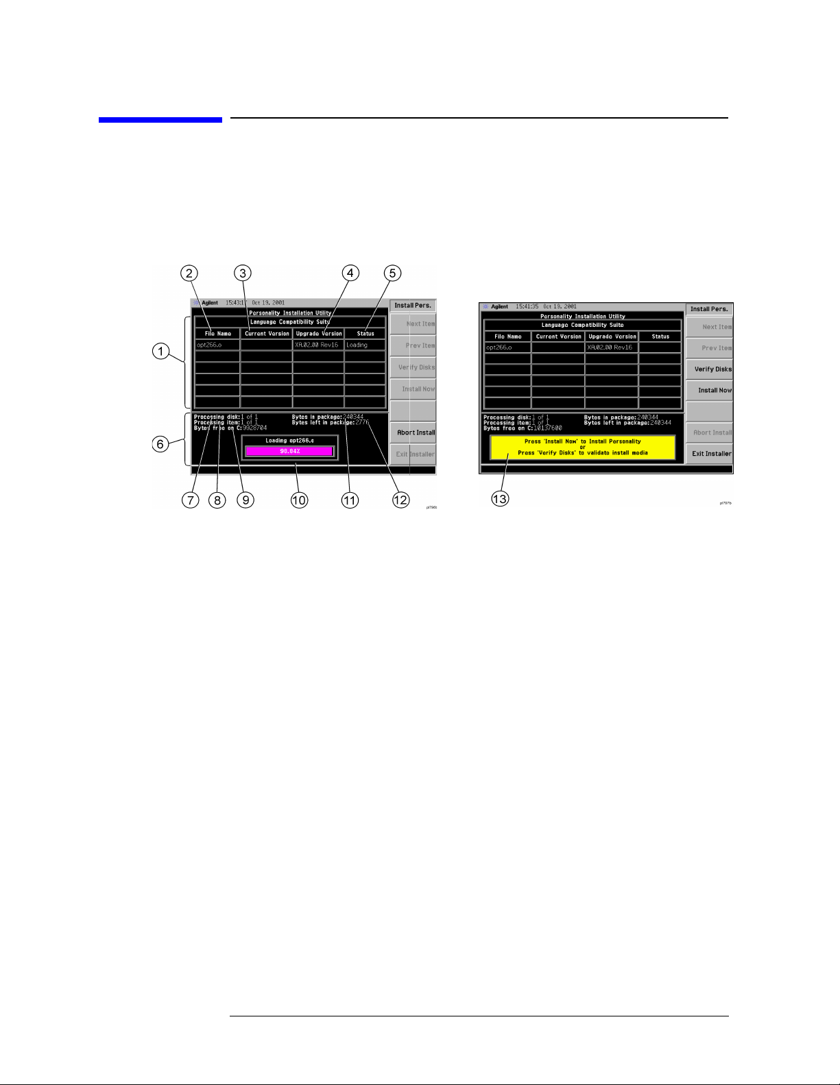
Getting Started
Installer Screen and Menu
Installer Screen and Menu
The top portion of the install screen is a table in which the files that are
about to be installed are listed. The bottom portion of the screen
contains information needed to track the progress of the install.
1File Table displays the files to be installed and various file
information. If there are more then six files,
allow you to scroll the table to view additional items.
2File Name dis play s the nam e of th e files o n the installation disk.
3 Current Version displays the version of the file that is currently
installed in the instrument. (This field will be blank if this file is not
currently installed in the instrument or if the file is a data file that has
no version.)
4 Upgrade Version shows the versio n of the f ile on the instal l dis k.
This is the vers ion of the file that wil l re place the cu rr ently installed
version.
5 Status is updated to reflect wh at the ins talle r is do ing to the cu rr e nt
file as the install progress. The valid messages seen in this column are
listed in Table 1-3 on page 7.
6Data Field contains a statu s bar an d variou s statu s information.
7 Processing disk shows t h e d isk that is cur rentl y bein g read.
8 Processing item shows the file that is being processes by ite m
number.
9 Bytes free on C is the number of bytes currently free on the
instrument C: drive.
Next Item and Prev Item
6 Chap ter 1
Page 27

10 Status Bar contains a status bar that runs from 0 to 100% and tracks
the progress of the current step and a message line displays the step
that is currently bein g execu t ed.
11 Bytes in package lists the number of bytes in the install package/ fill.
12 Bytes left in package lists the nu mb er of byt es left to be read.
13 Message and error popup window that displays over the stat us bar.
Information in this box will prompt you f o r action required to proceed
to the next phase of th e instal lation. It may al so inform yo u of errors i n
the installation process and may prompt you for action required to
correct the problem.
Table 1-3 Installer Status Messages
Failed This means that something has gone wrong while processing
this item. It is a fatal error and the ins tallation can not be
completed. The installer will try to get the system back to a
good state wh ich ma y ent ail compl etely removing the currently
installed personality.
Getting Started
Installer Screen and Menu
Loading The file is currently being copied from the install media to the
instrument’s file system.
Verifying T his may mean one of two things:
1. If “Verify Disks” was pressed then Verifying means that the
installer is curren tly read ing the install media a nd
comparing the known checksums to ensure the data is good .
2. If “Install Now” was pr es se d, the n Verifyin g mea n s tha t the
installer is reading what was just loaded to ensure the
checks um i s co rrect.
Loaded This means that the data has been placed on the instrument
disk but has not yet been registered with the firmware.
Installed This means that the data has been loaded into the instrument
and registered. The ins tall f or this file is complete.
Skipping This means that the installer has determ ine d that this f ile
does not need to be loaded into the instrument.
Chapter 1 7
Page 28

Getting Started
T r oubleshooting the Installer
Troubleshooting the Installer
If the installation process stalls or fails in another way, follow these
steps to resolve you r pro b lem.
1. If the inst ru ment stops the update process befor e a ll the disks are
loaded proceed as follows:
a. Press
b. Re t u rn to ste p 1 u nd e r “Installing the Option 26 6 S o ft ware ” on
page 4.
2. If the instrument fails after rep eating the installati on procedure , get
in touch with your nearest Agilent sales and service office for
assistance. Please provide the following information:
Model Number:
Serial Number:
State t h at yo u are having tr ouble insta ll in g Option 26 6.
Exit Installer to abort the process.
8 Chap ter 1
Page 29

Getting Started
T r oubleshooting the Installer
Installing Option 266 - PSA Series Analyzers Only
When you install Option 266, follow the process described below. See
“Loading an Optional Measurement Personality” on page 10
Adding additional measurement personalities requires purchasing a
retrofit kit for the desired option. The retrofit kit contains the
measurement personality firmware and a license key certificate. It
documents the license key number that is specific for your option and
instrument serial number.
Why Aren’t All the Personality Options Loaded in Memory?
There are many measurement personality options available for use
with this instrument. Some versions of instrument hardware may not
have enough memory to accommodate all the options that you have
ordered. If this is the case you will need to swap the applications in/out
of memory, as needed. It may be possible to upgrade your hardware to
have more memory. Contact yo u r local sales /s e rvice office.
Available Measurement Personality Options
To order a measurement personality option you need the instrument
model number, the host ID and the serial number.
Requ ired Information: Front Panel Key Path:
Model #:
__________________
Host ID:
__________________
Instrument
Serial Number:
__________________
NOTE The instrument must have Option B7J in order to add most of the
System, Show System
System, Show System
measurement personality options. (cdmaOne, cdma2000, W-CDMA,
GSM, EDGE, NADC, PDC.)
Chapter 1 9
Page 30

Getting Started
T r oubleshooting the Installer
Available Personality Options
Phase noise measurement personality 226 2.6 MB
Basic measurement personality with
digital demod hardware
GSM (with EDGE) measurement
personality
cdmaOne measurement personality BAC 2.0 MB
NADC measurement personalities (sold
with PDC)
PDC measurement personalities (sold with
NADC)
HP 8566B/68B Code Compatibility 266
W-CDMA measurement personality BAF
cdma2000 measur em ent p ersonality B78
1xEV-DO measurement personality 204
a
Option File Si ze (P SA
Rev: A.02.04)
B7J Cannot be
deleted
202 3.3 MB
BAE 1.3 MB
BAE 1.4 MB
0.65 MB
4.2 MB
3.8 MB
6.0 MB
b
c
c
c
Shared measurement libr ar y n/a 1.5 MB
a. Available as of the print date of this guide.
b. This option is free and does not require a license key. Install-
ing Option 266 Code Compatibility on a PSA series analyzer
autom at ically uninstall s all incomp atible personality optio n s.
Conversely , installing any incompatible personality option will
uninstall the Option 266 Code Compatibility option.
c. Some personality options use a shared measurement library.
You have to add the memory requirements of this library to
the value needed for the option. If you are loading multiple
personalities that use this library, you only need to add this
memory re qu i re ment once.
Loading an Optional Measurement Personality
You m ust load the desired personality option into the instrument
memory. Loading can be done from a fi rmw are CD -ROM or the internet
location. An automatic loading program comes with the files and runs
from you r PC.
NOTE When you add a new option, or update an existing option, you will get
the updated version of all your current options since they are reloaded
simultane ous ly. This process may also require yo u to up dat e t he
instrume n t co re firmware so that it is comp at ible with the n e w option.
10 Chap ter 1
Page 31

Getting Started
T r oubleshooting the Installer
You may not be able to fit all of the available measurement
perso n aliti e s i n in s t rument me mo ry at th e sa me t ime. You may need to
delete an existing option file from memory and load the one you want.
Use the automatic update program that is provided with the files.
The approximate memory requirements for the options are listed
above. These numbers are worst case examples. Some options share
components and libraries , therefore the total memory usage of mul ti ple
options may not be exactly equal to the combined total.
You can install an updated version of firmware and your licensed
options using a LAN connection and your PC. Instructions for loading
future firmware updates are available from the following internet
location: http://www.agilent.com/find/psa/
NOTE There is no license key for Option 266. You therefore do not need to
follow the usual license key installation process.
Chapter 1 11
Page 32

Getting Started
Configuring Option 266 - ESA and PSA Analyzers
Configuring Option 266 - ESA and PSA
Analyzers
Figure 1-1 and Figure 1-2 show the menu maps to conf ig ure Opti on 266
(HP 8566B/68B Code Compatibility) on your spectrum analyzer.
Pressing
analyze r (o r System, Configure Remote Lang, Language on an ESA-E
Series analyzer) a ll ows y ou to select the remote p r ogra mming langua ge
for the instru ment you are re pl acing.
System, Config I/0, Configure Remot e Lang, Language on a PSA Series
12 Chap ter 1
Page 33

Getting Started
Configuring Option 266 - ESA and PSA Analyzers
Figure 1-1 System Menu Map f or Option 266 on ESA-E Series Analyzers
Figure 1-2 System Menu Map f or Option 266 on PSA Series Analy zers
Chapter 1 13
Page 34

Getting Started
Analyzer Settings When Changing Language
Analyzer Settings When Changing Language
When you power your ESA-E or PSA analyzer on for the first time, the
language is set to SCPI. Subsequent changes of Remote Language
cause the following settings to be changed:
SCPI • The analyzer is preset
• The H P 8566 B /68B Code C o mpatibility application is u n coupled
HP8566B • The analyzer is preset
• Number of trace points is set to 1001
• Start frequency is set to 2 GHz
• Stop frequency is set to 22 GHz
• RF coupling is set to DC
(See Note below)
• Sweep and FFT couplings are set
HP8568B • The analyzer is preset
• Number of trace points is set to 1001
• Start frequency is set to 0 Hz
• Stop frequency is set to 1.5 GHz
• RF coupling is set to AC
(See Note below)
• Sweep and FFT couplings are set
NOTE RF Coupling is only available o n PS A an alyzers w it h a maximum
frequency of 26.5 MHz or lower, and on ESA analyzers that have
Option U KB (Low Frequency Extension) installed.
Analyzer Settings After Powering On and Off
Whenever you switch your ESA-E or PSA analyzer off, its current
language setting is saved. When you next switch it on, it will power up
with exactly the same language setting as when you switched it off.
14 Chap ter 1
Page 35

Getting Started
The Configure Remote Lang Screen Menu - ESA-E and PSA Analyzers
The Configure Remote Lang Screen Menu ESA-E and PSA Analyze rs
Configure
Remote Lang
This key displays a menu allowing you to select the remote language
you wish to use, and to determine how command error messages are
stored and displayed.
Language This key allows you to select which remote programming language you
wish to use.
SCPI Selects the
SCPI remo t e pro gra mmi ng la ngu age . Thi s is
the default setting after installation.
HP8566B Select s the
HP8566B remote progra mming langua ge an d
sets the response to the remot e programming command
‘ID’ to HP8566B. It also performs an instrument preset,
setting Span and Trace Points appropriately.
HP8568B Select s the
HP8568B remote progra mming langua ge an d
sets the response to the remot e programming command
‘ID’ to
HP8568B. It also performs an instrument preset,
setting Span and Trace Points appropriately.
NOTE Setting the remote language to HP8566B or to HP8568B does not affect
the response to the SCPI command ‘*IDN?’ This command will still
return the mod el numbe r and fi rmwa re vers ion nu mber of the ESA- E or
PSA analyzer.
Command Err This key determines whether or not command errors are displayed on
the screen. When set to
On, error me ssa ge s generated by u n re cognized
commands or command arguments are displayed on the screen. When
set to
Off, error messages generated by unrecognized commands are not
displ aye d. The c ur r e n t settin g is under lined on th e key labe l, an d this
setting is reversed each time the key is pressed.
NOTE Command Err is set to On after Option 266 has been installed.
Thereafter, the latest setting will always be retained, even after a
preset has been performed.
Chapter 1 15
Page 36

Getting Started
The Configure Remote Lang Screen Menu - ESA-E and PSA Anal yzers
Cmd Error Log This key sets command error logging On or Off. When set to On, all error
messages are stored in a log file, regardless of whether they have been
displayed on the screen. When set to Off, no further com ma n d e rro r
messages are written to the log file.
The log file is an ASCII text file called LOGF IL E.T XT on the C: drive. It
has a maximum size of 32 KB. Once it has reached its maximum size,
no furthe r e rro r messages will be recorded, but a me ssage will be
displayed prompting you to clear the log file. Switching
Off does not clear the log file. Only the Clear Command Error Log softkey
Cmd Error Log to
will clear t h e er ro r lo g.
NOTE Command Err Log is set to On after O pt ion 266 has been i n st alled.
Thereafter, the latest setting will always be retained, even after a
preset has been performed.
Clear Command
Error Log
This key allows yo u t o cle ar all messages from t he comman d error log
file LOGFILE.TXT.
16 Chap ter 1
Page 37

Getting Started
Differences Between Option 266 Commands and the Original HP8566B/HP 8568B Commands
Differences Between Option 266 Commands
and the Original HP 8566B/HP 8568B
Commands
The following table lists commands that behave differently in Agilent
Option 266 when c om pared to the o riginal HP 8566B and H P 8568B
analyzers:
Table 1-4 Analyzer Commands That Behave Differently in Option 266
Command HP 8566B / HP 8568B
Analyzers
AT Specifies RF input
annotation.
CF Specifies the center
frequency.
DET Selects the type of
detection - sample,
normal, positive pea k or
negative peak - that is
applied to the input signal.
DL Specifie s the display line
level.
ESA-E Option 266 PSA Option 266
Maximum attenuation is
limited to 65 dB.
The OA option only
returns the current valu e
to the controller. It does
not set the active func tio n.
The OA option only
returns the current valu e
to the controller. It does
not set the active func tio n.
Normal detection is not
possible in the ESA, so
selection of NRM
command option will
default to POS (Positive
Peak) detection.
The OA option only
returns the current valu e
to the controller. It does
not set the active func tio n.
The OA option only
returns the current value
to the controller. It does
not set the active function.
The OA option only
returns the current value
to the controller. It does
not set the active function.
Normal detection is
possible.
The OA option only
returns the current value
to the controller. It does
not set the active function.
FA Specifies the start
frequency value.
FB Specifie s the stop
frequency value.
Chapter 1 17
The OA option only
returns the current start
frequency value to the
controller. It does not set
the active functio n to t he
start frequency.
The OA option only
returns the current stop
frequency value to the
controller. It does not set
the active functio n to t he
stop frequency.
The OA option only
returns the cu rre nt start
frequency value to the
controller. It does not set
the active function to the
start frequency.
The OA option only
returns the current stop
frequency value to the
controller. It does not set
the active function to the
stop frequ e ncy.
Page 38

Getting Started
Differences Between Option 266 Commands and the Original HP8566B/HP 8568B Commands
Table 1-4 Analyzer Commands That Behave Differently in Option 266
Command HP 8566B / HP 8568B
Analyzers
FOFFSET Specifies the frequency
offset.
FPKA Performs a fas t preselecto r
peak and return s the
measured value of the
active ma r k er.
I1 [one] Sets RF coup ling to DC. This command is no t
ESA-E Option 266 PSA Option 266
The OA option only
returns the current value
to the controller. It does
not set the active fun ctio n .
Adjusts the centering of
the preselector filter to
optimize the amp litude
accuracy at the active
marker frequency.
This functio nalit y is on ly
available in ESA-E series
analyzers whose frequency
range ex tends b e yond 3
GHz, that is the E4404B,
the E4405B, and the
E4407B analyzers.
supported on model
number E4401B. It is only
supported on model
number E4407B if Option
UKB has been insta lle d.
The OA option only
returns the current valu e
to the controller . It does
not set the active fu nc tio n.
Adjusts the centering of
the preselector filter to
optimize the amplitude
accuracy at the active
marker frequency.
This functionality is
available in all PSA series
analyzers.
This command is only
supported on PSA
analyzers with a frequency
range up to 26.5 GHz, that
is the E4440A, the E4443A
and the E4445A.
Note also that the
HP 8568B analyzer has
two R F port s w hereas the
ESA only has one.
I2 [two] Sets RF c oup ling to AC. This command is not
supported on model
number E4401B. It is only
supported on model
number E4407B if Option
UKB has been insta lle d.
Note also that the
HP 8568B analyzer has
two R F port s w hereas the
ESA only has one.
KS, Specifies the maximum
signal level applied to the
input mi xer for signals at
or below the reference
level.
The OA option only
returns the current value
to the controller. It does
not set the active fun ctio n .
Note also that the
HP 8568B analyzer has
two RF ports whereas the
PSA only has one.
This command is only
supported on PSA
analyzers with a frequency
range up to 26.5 GHz, that
is the E4440A, the E4443A
and the E4445A.
Note also that the
HP 8568B analyzer has
two RF ports whereas the
PSA only has one.
The OA option only
returns the current valu e
to the controller . It does
not set the active fu nc tio n.
18 Chap ter 1
Page 39

Getting Started
Differences Between Option 266 Commands and the Original HP8566B/HP 8568B Commands
Table 1-4 Analyzer Commands That Behave Differently in Option 266
Command HP 8566B / HP 8568B
Analyzers
KS= (on
HP 8568B
analyzers)
KSa Selects normal dete ct io n. Normal detection is not
KSE Activates the title mode,
Specifies the resolutio n of
the m a rker freque n cy
counter.
using ‘@’ as the defa u lt
termination character .
ESA-E Option 266 PSA Option 266
Language set to HP8566B:
not supported.
Language set to HP8568B:
No difference.
possible in the ESA, so
selection of KSa comman d
option will default to PO S
(Positive Peak) detection.
The only acceptable
termination characters are
‘@’ and Carriage Return.
The ‘@’ character does not
appear on the screen.
Language set to HP8566B:
not supported.
Language set to HP8568B:
Setting the marker
frequency counter
resolution changes the
gate time. The gate time is
calculated by:
GateTime = 1/(Res. value)
Normal detection is
possible.
The only acceptable
termination characters are
‘@’ and Carriage Return.
The ‘@’ character does not
appear on the screen.
KSG Enables video averaging. The OA option only
returns the current valu e
to the controller. It does
not set the active func tio n.
KSM Displays the noise density
at the marker.
KST (on
HP 8566B
analyzers)
KSV Specifies frequency offset
Performs a fast preset on
HP 8566B analyzers.
values.
The OA option only
returns the current valu e
to the controller. It does
not set the active func tio n.
Language set to HP8566B:
ESA series analyzers
cannot perform a fast
preset. The KST c ommand
performs an instrument
preset instead, setting the
analyzer back to its factory
default settings.
The OA option only
returns the current valu e
to the controller. It does
not set the active func tio n.
The OA option only
returns the current value
to the controller. It does
not set the active function.
The OA option only
returns the current value
to the controller. It does
not set the active function.
Language set to HP8566B:
PSA series analyzers
cannot pe rform a fast
preset. The KST command
performs an instrument
preset instead, setting the
analyzer back to its factory
default settings.
The OA option only
returns the current value
to the controller. It does
not set the active function.
Chapter 1 19
Page 40

Getting Started
Differences Between Option 266 Commands and the Original HP8566B/HP 8568B Commands
Table 1-4 Analyzer Commands That Behave Differently in Option 266
Command HP 8566B / HP 8568B
Analyzers
KSx Selects no rmal external
triggering.
Fast sweep times in zero
span ca n cause th e
displayed trace to flicker.
KSy Selects normal video
triggering.
Fast sweep times in zero
span ca n cause th e
displayed trace to flicker.
KSZ Specifies the reference
level offset.
LG S e ts amp litu de read out to
logarithmic scale.
ESA-E Option 266 PSA Option 266
The displayed trace is
automatica lly refreshed.
All flickering has been
eliminated.
The displayed trace is
automatica lly refreshed.
All flickering has been
eliminated.
The OA option only
returns the current value
to the controller. It does
not set the active fun ctio n .
The OA option only
returns the current value
to the controller. It does
not set the active fun ctio n .
The displayed trace is
automatically re f re shed.
All flickering has bee n
eliminated.
The displayed trace is
automatically re f re shed.
All flickering has bee n
eliminated.
The OA option only
returns the current valu e
to the controller . It does
not set the active fu nc tio n.
The OA option only
returns the current valu e
to the controller . It does
not set the active fu nc tio n.
M2 Sets norma l mar k er. The OA option only
returns the current value
to the controller. It does
not set the active fun ctio n .
M3 Measures the amplitude
and frequency differences
between the act ive a nd the
delta marker.
No difference if Marker
Noise (MKNO IS E) is
switched on when the
measurement is made.
If MKNOISE is switched
on after the measurement
has been made, the
amplitude measured is
that between th e nois e
density and the carrier
signal.
The OA option only
returns the current value
to the controller. It does
not set the active fun ctio n .
The OA option only
returns the current valu e
to the controller . It does
not set the active fu nc tio n.
No difference if Marker
Noise (MKNOISE) is
switched on when the
measurement is made.
If MKNOISE is switched
on after the measurement
has been made, the
amplitude measu red is
that between the noise
density and the ca rrier
signal.
The OA option only
returns the current valu e
to the controller . It does
not set the active fu nc tio n.
20 Chap ter 1
Page 41

Getting Started
Differences Between Option 266 Commands and the Original HP8566B/HP 8568B Commands
Table 1-4 Analyzer Commands That Behave Differently in Option 266
Command HP 8566B / HP 8568B
Analyzers
MKA Specifies the amplitude of
the active marke r in dBm
when the active marker is
of the fixed or amplitude
type.
MKD Measures the amplitude
and f r e que ncy di ff eren c es
between the active and the
delta marker.
ESA-E Option 266 PSA Option 266
Only supports the query
option.
No difference if Marker
Noise (MKNOISE) is
switched on when the
measurement is made.
If MKNOISE is switched
on after the measurement
has been made, the
amplitude measu red is
that between the noise
density and the carrier
signal.
The OA option only
returns the current valu e
to the controller. It does
not set the active func tio n.
Only suppor ts th e qu ery
option.
No difference if Marker
Noise (MKNOISE) is
switched on when the
measurement is made.
If MKNOISE is switched
on after the measurement
has b een ma de, the
amplitude measured is
that between th e nois e
densit y and t h e carrier
signal.
The OA option only
returns the current value
to the controller. It does
not set the active function.
MKFCR Specifies the resolution of
the m a rker freque n cy
counter.
MKREAD Selects the type of trace
information th at is
displayed.
MKN Sets normal marker. The OA option only
No difference. Setting the marker
Will not accept the FFT
(Fast Four i er Transform )
keyword.
returns the current valu e
to the controller. It does
not set the active func tio n.
frequency counter
resolution changes the
gate time. The gate time is
calculated by:
GateTime = 1/(Res. value)
WIll not accept the FFT
(Fast Fourier Transform)
keyword.
The OA option only
returns the current value
to the controller. It does
not set the active function.
Chapter 1 21
Page 42

Getting Started
Differences Between Option 266 Commands and the Original HP8566B/HP 8568B Commands
Table 1-4 Analyzer Commands That Behave Differently in Option 266
Command HP 8566B / HP 8568B
Analyzers
ML Specifies the maximum
signal level applied to the
input mi xer for signals at
or below the reference
level.
OT Output Trac e Annotations
(Sends 32
character-strings, each of
up to 64 characters)
ESA-E Option 266 PSA Option 266
The mixer level is
calculated using the
following equation.
Mixer Level = Ref. Level Attenuation + Ext. Amp
Gain.
The external amplif ier
gain is not preset by doing
an IP in case the
instrument is measuring a
large signal.
The OA option only
returns the current value
to the controller. It does
not set the active fun ctio n .
String number 27 (‘dirty
marker’ status repo rt) is
not supported.
The mixer level is
calculated using the
following equation.
Mixer Level = Re f. Level Attenuation + Ext. Amp
Gain.
The external amplifier
gain is not preset by doing
an IP in case the
instrument is measuring a
large signal.
The OA option only
returns the current valu e
to the controller . It does
not set the active fu nc tio n.
No difference.
PLOT Transfers trace data,
graticule parameters and
graticule annotation
directly to a plotte r.
PP Peaks preselector. Adjusts the centering of
PWRBW Power Bandwid th In the HP 8566B/8568B,
Prints the scree n disp lay
on a printer rath e r than
transferring d ata to a
plotter.
the preselector filter to
optimize the amp litude
accuracy at the active
marker frequency.
This functio nalit y is on ly
available in ESA-E series
analyzers whose frequency
range ex tends b e yond 3
GHz, that is the E4404B,
the E4405B, and the
E4407B analyzers.
the trace stops when the
PWRBW command is
issued. The trace does not
stop in the ESA-E series
analyzers.
Prints the scre en di sp lay
on a printer rather than
tra n sferr ing data to a
plotter.
Adjusts the centering of
the preselector filter to
optimize the amplitude
accuracy at the active
marker frequency.
This functionality is
available in all PSA series
analyzers.
In the HP 8566B/ 8568 B,
the trace stops when the
PWRBW command is
issued. The trace does not
stop in the PSA series
analyzers.
22 Chap ter 1
Page 43

Getting Started
Differences Between Option 266 Commands and the Original HP8566B/HP 8568B Commands
Table 1-4 Analyzer Commands That Behave Differently in Option 266
Command HP 8566B / HP 8568B
Analyzers
R4 Activates the
units-key-pressed and
illegal-command service
requests.
RB Specifie s the res o lution
bandwidth.
RC Recalls registers
containing a set of
instrument states.
ESA-E Option 266 PSA Option 266
The units-key-press ed
service request can not be
supported sin ce f ront
panel interaction is not
allowed.
Default values ma y be
different to the HP 8566B.
Please refer to your ESA-E
or PSA User’s Guide for
restrictions on the
resolution bandw id th
range.
The OA option only
returns the current valu e
to the controller. It does
not set the active func tio n.
Recalling the previous
state data (RC 7) is not
supported.
The units-key-pressed
service request cannot be
supported since front
panel interac tio n is no t
allowed.
Defa ult val ue s may be
different to the HP 8566B.
Please refer to your ESA-E
or PSA User’s Guide for
restrictions on the
resolution bandwidth
range.
The OA option only
returns the current value
to the controller. It does
not set the active function.
Recalling the previous
state data (RC 7) is not
supported.
RCLS Recalls registers
containing a set of
instrument states.
REV Returns the firmware
revision number.
RL Sets the reference level. The OA option only
ROFFSET Sets the refere nce level
offset.
RQS Sets a bit mask for service
requests.
SMOOTH Smooths the trace. Some differences in the
Recalling the previous
state data (RCLS 7) is not
supported.
Returns the build date of
your Option 266 (in YYWW
format).
returns the current valu e
to the controller. It does
not set the active func tio n.
The OA option only
returns the current valu e
to the controller. It does
not set the active func tio n.
Some differences may be
noticed in the value
returned by a query.
trace display may be
noticed.
Recalling the previous
state data (RCLS 7) is not
supported.
Returns the build d ate of
your Option 266 (in YYWW
format).
The OA option only
returns the current value
to the controller. It does
not set the active function.
The OA option only
returns the current value
to the controller. It does
not set the active function.
Some differences may be
noticed in the valu e
returne d b y a que ry.
Some differences in the
trace display m ay be
noticed.
Chapter 1 23
Page 44

Getting Started
Differences Between Option 266 Commands and the Original HP8566B/HP 8568B Commands
Table 1-4 Analyzer Commands That Behave Differently in Option 266
Command HP 8566B / HP 8568B
Analyzers
SP Sets the frequency span. The OA option only
SS Se ts the center frequency
step si ze.
ST Sets the sweep time. The OA option only
TH Blanks the display of
signals below the
threshold leve l.
ESA-E Option 266 PSA Option 266
returns the current value
to the controller. It does
not set the active fun ctio n .
The OA option only
returns the current value
to the controller. It does
not set the active fun ctio n .
returns the current value
to the controller. It does
not set the active fun ctio n .
No change will be noticed
in the display.
Note that the PEAKS and
MKPK co m m a nd s can
cause all values be low the
threshold level to be
disregarded.
The OA option only
returns the current valu e
to the controller . It does
not set the active fu nc tio n.
The OA option only
returns the current valu e
to the controller . It does
not set the active fu nc tio n.
The OA option only
returns the current valu e
to the controller . It does
not set the active fu nc tio n.
No change will be noticed
in the display.
Note that the PEAKS and
MKPK commands can
cause all values below the
threshold leve l to be
disregarded.
VB S p ecif ies the vid e o filt e r
bandwidth.
The OA option only
returns the current value
to the controller. It does
not set the active fun ctio n .
Default values may be
different to the HP 8566B.
Please refer to your ESA-E
or PSA User’s Guide for
restr ictions o n the video
bandwidth range.
The OA option only
returns the current value
to the controller. It does
not set the active fun ctio n .
The OA option only
returns the current valu e
to the controller . It does
not set the active fu nc tio n.
Default values ma y be
different to the HP 8566B.
Please refer to your ESA-E
or PS A Us e r’s Guide for
restrictions on the video
bandwidth range.
The OA option only
returns the current valu e
to the controller . It does
not set the active fu nc tio n.
24 Chap ter 1
Page 45

Getting Started
Differences Between Option 266 Commands and the Original HP8566B/HP 8568B Commands
Table 1-4 Analyzer Commands That Behave Differently in Option 266
Command HP 8566B / HP 8568B
Analyzers
VAVG Enables video averaging,
displaying the orig inal
trace in Trace C.
Sweep time remains
unchanged.
VBO Specifies the ratio of video
to resolution bandwidths
when coupled.
ESA-E Option 266 PSA Option 266
Only displays the average
trace in Trace A.
Sweep time changes .
Difference s in ho w th e
average is calculated when
other setti ngs hav e
changed.
No change. Some differences may be
Only displays the averag e
trace in Trace A.
Sweep time changes.
Differences in how the
average is calculated when
other se tting s have
changed.
noticed when VBO of 1 or
of -1 is used.
Chapter 1 25
Page 46

Getting Started
Differences Between HP8566B and HP8568B Remote Languages in Option 266
Differences Between HP8566B and HP8568B
Remote Languages in Option 266
The following table lists Option 266 commands that behave differently
in the HP8566B remote language when compared to the HP8568B
remote language:
Table 1-5 Option 266 Commands That Behave Differently in the HP8566B
and HP8568B Remote Languages
Command HP8566B Remote
Language
FPKA Valid and supported Invalid - HP 8566B command
I1 [one] Invalid - HP 8568B command
only
I2 [two] Invalid - HP 8568B command
only
KSK Valid and supporte d Valid command o n the
KSN Valid and supported Valid command on the
KST Valid and supported Valid command on the
HP8568B Remote
Language
only
Valid and supported (but see
Table 1-4 on page 17 and “I1
[one] Set RF Coupling to DC”
on page 118)
Valid and supported (but see
Table 1-4 on page 17) and “I2
[two] Set RF Coupling to AC”
on page 120
HP 8568B but unsupported
in Option 266
HP 8568B but unsupported
in Option 266
HP 8568B but unsupported
in Option 266
KS= Valid command on the
HP 8566B but unsupported
in Option 266
LF Valid and supported Invalid - HP 8566B command
MC0 [zero] Invalid - HP 8568B command
only
MC1 [one] Invalid - HP 8568B command
only
MKFC Invalid - HP 8568B command
only
26 Chap ter 1
Valid and supported
only
Valid and supported
Valid and supported
Valid and supported
Page 47

Getting Started
Differences Between HP8566B and HP8568B Remote Languages in Option 266
Table 1-5 Option 266 Commands That Behave Differently in the HP8 566B
and HP 8568B Remote Languages
Command HP8566B Remote
Language
MKFCR Invalid - HP 8568B command
only
PP Valid and supported Invalid - HP 8566B command
HP8568B Remote
Language
Valid and supported
only
Chapter 1 27
Page 48

Getting Started
Running Software that Requires SCPI Commands
Running Software that Requires SCPI
Commands
When Remote Language HP8566B or HP8568B has been selected, you
will only have access to a very small subset of SCPI commands. If you
are not famil iar wi th the SCPI remote pr ogram ming la nguage , Chapter
5, “A Brief Introduction to the SCPI Language,” on page 259 cont ains
some useful information.
The SCPI commands available while using the remote language
HP8566B or HP8568B are:
•
*IDN?
Queries an d ret u rn s t h e inst ru ment identifi cat i on st ri n g.
*RST
•
Performs an instrument preset.
•
:SYSTem:LANGuage SCPI|HP8566B|HP8568B
Sets the current remote language.
This command i s only availab le if you have Option 266 installe d o n
your analyzer.
NOTE Agilent Technologies recommend that you do not repeatedly swap to
and from the SCPI language within your programs.
•
:SYSTem:LANGuage?
Queri es an d re t u rn s t h e cu rre n t re mote language.
This command i s only availab le if you have Option 266 installe d o n
your analyzer.
•
[:SENSe]:SWEep:TYPE AUTO|SWEep|FFT
Sets the Sweep Type.
•
[:SENSe]:SWEep:TYPE?
Queries and returns the Sweep Type.
•
[:SENSe]:SWEep:TYPE:AUTO:RULes SPEed|DRANge|DYNamicrange
Sets the auto rule setting for FFT and Sweep Type.
[:SENSe]:SWEep:TYPE:AUTO:RULes?
•
Queries and returns the auto rule setting for FFT and Sweep Type.
•
:SYSTem:OPTion?
Returns a list o f installed options.
28 Chap ter 1
Page 49

Getting Started
Running Software that Requires SCPI Commands
If Option 266 is instal le d o n yo u r analyze r, the string “266” will
appear in the returned string . In the foll owing example , options B7J,
266, and 1D S are all installed.
Example: “B7J,2 66, 1DS ”
To r etur n the a nalyzer to its full ESA or PSA SCPI capab il ity, you must
specify the remote language as SCPI.
Chapter 1 29
Page 50

Getting Started
Service and Calibration
Servi ce and Calib r ation
Since the Performance Verification and Adjustment Software uses the
SCPI command language, you will need to set Remote Language to
SCPI prior to calibration or service of your Agilent spectrum analyzer.
When your analyzer is returned from an Agilent Technologies service
center, you may have to reinstall Option 266. Refer to
“Installing/Uninstall ing Option 266 - ESA-E Series Analyzers Only” on
page 4 or “In s t alling Option 266 - PS A S e ries An alyzers Only” on page 9
30 Chap ter 1
Page 51

Getting Started
Documentation for Option 266
Documentation for Option 266
Spectrum Analyzers with Option 266
When you purchase your ESA-E Series or PSA Series spectrum
analyzer with the HP 8566B/68B Code Compatibility (Option 266), you
will receive this man u al - the HP 8566B/68B Code Co mpatibility
Guide. For information on ESA series analyzers and other related
documentation, refer to the ESA web site at
http://www.agilent.com/find/esa/. For information on PSA series
analyzers and other related documentation, refer to the PSA web site at
http://www.agilent.com/find/psa/.
This HP 8566B/6 8B C o d e C o mpatibility Gu id e is not designed to be a
compr e h e n sive guide to all HP 8566B/68 B co mmands. It giv e s bri ef
descriptio ns of t h e sup po rt ed co mmands, and highli gh ts i mportant
functional or behavioral differences that you should be aware of when
transferring existing HP 8566B or HP 8568B code to your ESA-E series
or PSA analyzer. F or a fuller descripti on of the commands, refer to the
HP 8566B or HP 85 68B ’s Operating and Programming Manual.
Spectrum Analyzer Updates
For the latest informa t ion abou t th is instrument, including so ft wa re
upgra de s, ap plication in format io n , an d product in fo rmation , please
visit the URL listed below.
Updating the Firmware and Software
Updated versions of the Agilent Spectrum Analyzers’ firmware and
software will be av ailable via seve ra l sources. In f o rmation o n th e latest
firmware a n d so ft ware re vision can be accessed throu g h the fo llowing
URL.
URLs to Obtain Update Information
For ESA analyzers: http://www.agilent.com/find/esa /
For PSA analyzers: http://www.agilent.com/find/psa/
NOTE If you have purchased Option 266 as an upgrade, the latest version of
the analyzer’s firmware has been included and should be lo aded into
your instrument before installing the Option 266.
Chapter 1 31
Page 52

Getting Started
Documentation for Option 266
32 Chap ter 1
Page 53

2 HP 8566B and HP 8568B
Command List
33
Page 54

HP 8566B and HP8568B Command List
T able of HP 8566B and HP 8568B Commands
Table of HP 8566B and HP 8568B Commands
The follo wi n g t able lists all H P 8566B and H P 8568B prog ramming
commands, and indicates which are supported in Option 266. R e fe r t o
the alphabetical listing of commands in Chapter 4 , “Programming
Commands,” on page 61 for more detailed information about each
supp orted command.
34 Chap ter 2
Page 55

HP 8566B and HP8568B Command List
Table of HP 8566B and HP 8568B Commands
Table 2-1 Alphanumeric List of All HP 8566B/HP 8568B Commands and
Their Option 266 Suppor t
HP8566B/
HP8568B
Command
A1 [one] Yes Clear write of Trace A See page 65 for more
A2 [two] Yes Maximum hold for Tr ace A See pag e 66 for mo re
A3 [three] Yes View Trace A See page 6 7 for more
A4 [four] Yes Blank Trace A See pag e 68 for mo re
ABS No Puts the absolute value of the source
ADD No Operand 1 + Operand 2 into
AMB Yes A minus B into A See pag e 69 for mo re
AMBPL Yes (A minus B) + DL into A See page 70 for more
Supported
in Option
266?
Command Description Note
details
details
details
details
Returns error - "CMD
into the destinatio n .
destination
NOT SUPPORTED"
Returns error - "CMD
NOT SUPPORTED"
details
details
ANNOT Yes Turns the Annotation ON or OFF Not supported on PSA
See page 71 for more
details
APB Yes A plus B into A (Adds trace A and B
point by point and sends results to
A)
AT Yes Specifies input attenuation See page 7 3 for more
AUNITS Yes Specifies amplitude units for input,
output and display
AVG No Operand is averaged into
destination
AXB Yes Exchange A and B See pag e 76 for mo re
B1 [one] Yes Clear write of Trace B See pag e 77 for mo re
See page 72 for more
details
details
See page 75 for more
details
Returns error - "CMD
NOT SUPPORTED"
details
details
Chapter 2 35
Page 56

HP 8566B and HP8568B Command List
T able of HP 8566B and HP 8568B Commands
Table 2-1 Alphanumeric List of All HP 8566B/HP 8568B Commands and
Their Option 266 Support
HP8566B/
HP8568B
Command
B2 [two] Yes Ma ximum hol d for Trace B See page 78 for more
B3 [three] Yes View Trace B S ee page 79 for more
B4 [four] Yes Blank Trace B See page 80 for more
BL Ye s Trace B minus Display Line into B See page 8 1 for mor e
BLANK Yes Bl anks traces and stops the sweep.
BML Ye s Trace B minus Display Line into B See page 83 for more
BRD No Bus Read (Reads a 2 byte word at
BTC Yes Transfers trace B to trace C See page 84 for more
Supported
in Option
266?
Command Description Note
details
details
details
details
See page 82 for more
Trace is not upd ate d
the internal input/output) (This is a
service diagnostic function only)
details
details
Returns error - "CMD
NOT SUPPORTED"
details
BWR No Bus Write Word (Writes a 2 byte
word at the inter nal inp u t/ ou tput)
(This is a service diagnostic function
only)
BXC Yes Exchanges traces B and C point by
point
C1 [one] Yes Trace A minus Trace B into Trace A On See page 86 for more
C2 [two] Yes Trace A minus Trace B into Trace A
Off
CA Yes Couple Attenuator (Resets the
attenuation value so that a
continuous wave signal displayed at
the reference level will yield the
maximum mixer level (see ML
command) at the mixer input)
CF Yes Center Frequency See page 89 for more
Returns error - "CMD
NOT SUPPORTED"
See page 85 for more
details
details
See page 87 for more
details
See page 88 for more
details
details
36 Chap ter 2
Page 57

HP 8566B and HP8568B Command List
Table of HP 8566B and HP 8568B Commands
Table 2-1 Alphanumeric List of All HP 8566B/HP 8568B Commands and
Their Option 266 Suppor t
HP8566B/
HP8568B
Command
CLRAVG Yes Clear Average See pag e 91 for mo re
CLRW Y es Enables the Clear-Write Mode which
CNVLOSS No Selects the reference level offset to
COMPRESS No Compresses trace source to fit trace
CONCAT No Concatenates operands and sends
CONTS Yes Sets the analyzer to con tinu o us
CR Yes Couples the resolution bandwidth
Supported
in Option
266?
Command Description Note
details
See page 92 for more
continuously di sp lays any sign al s
present at the analyzer input
amplitude calibrate the display for a
mixer with a giv en los s
destination
new trace to destination
sweep mode
with the video b andwidth and s weep
time
details
Returns error - "CMD
NOT SUPPORTED"
Returns error - "CMD
NOT SUPPORTED"
Returns error - "CMD
NOT SUPPORTED"
See page 93 for more
details
See page 94 for more
details
CS Yes Couples the center frequency step
size to the span width (Step Size =
0.1 x Span Width) (1 major graticule
division)
CT Yes Couples the sweep time with the
resolution and video bandwidths
CTA N o Converts the operand values from
display units to absolute amplitude
units
CTM No Converts the operand values to
vertical display units
CV Yes Couples video bandwidth with the
resolution bandwidth and sweep
time
D1 [one] No Sets the display to norm al size,
selected with IP.
D2 [two] N o Sets the display to full CRT siz e. Returns error - "CMD
See page 95 for more
details
See page 96 for more
details
Returns error - "CMD
NOT SUPPORTED"
Returns error - "CMD
NOT SUPPORTED"
See page 97 for more
details
Returns error - "CMD
NOT SUPPORTED"
NOT SUPPORTED"
Chapter 2 37
Page 58

HP 8566B and HP8568B Command List
T able of HP 8566B and HP 8568B Commands
Table 2-1 Alphanumeric List of All HP 8566B/HP 8568B Commands and
Their Option 266 Support
HP8566B/
HP8568B
Command
DA Yes Display memory address Only DA 1, DA 1025 and
DD No Wr ite s two 8 byte s (binary) into the
DET Yes In p ut Dete c to r See page 99 for more
DISPOSE No Clears specified op erand s (Trace
DIV No Divide operand 1 by oper and 2, point
DL Yes Display Line Level (dBm ) See page 101 for mor e
DLE Yes Enable o r disables th e Di splay Line See page 102 for mor e
Supported
in Option
266?
Command Description Note
DA 3073 are supported
Returns error - "CMD
current or specified memor y addres s
& advances address by 1
Label, Var Identifier, Function
Identifier, Key Number)
by point
NOT SUPPORTED"
details
Returns error - "CMD
NOT SUPPORTED"
Returns error - "CMD
NOT SUPPORTED"
details
details
DONE Yes A synchronizing function - sends a
’1’ to the controller after the
command line is executed
DR No Display Read - sends the contents of
the current display address to the
controller
DSPLY No D isplays the value of a variable Returns error - "CMD
DT No D efine Terminator Returns error - "CMD
DW N o Display Write - sends a dec im al
value from the controller to the
display memory address
D3 [three] No Sets the display to expanded size. Returns error - "CMD
E1 [one] Yes Moves the active marker to the
maximum signal detected.
E2 [two] Yes Moves the active marker frequency
into the center frequenc y.
See page 103 for more
details
Returns error - "CMD
NOT SUPPORTED"
NOT SUPPORTED"
NOT SUPPORTED"
Returns error - "CMD
NOT SUPPORTED"
NOT SUPPORTED"
See page 104 for more
details
See page 105 for more
details
38 Chap ter 2
Page 59

HP 8566B and HP8568B Command List
Table of HP 8566B and HP 8568B Commands
Table 2-1 Alphanumeric List of All HP 8566B/HP 8568B Commands and
Their Option 266 Suppor t
HP8566B/
HP8568B
Command
E3 [three] Yes Moves the active marker frequency
E4 [four] Yes Moves the active marker to the
EE No Ena bles front panel number entry Returns error - "CMD
EK No Enables the data knob Returns error - "CMD
ELSE No Conditional command used in
EM No Erase Trace C memory addresses
ENDIF No Finishing off an IF command Returns error - "CMD
ENTER No Enter from GPIB, allows a function
Supported
in Option
266?
Command Description Note
See page 106 for more
or the delta marker frequency into
the center frequency step size.
reference leve l .
conjunction with an IF command
3072 through 4095
definition to enter data from the
GPIB port.
details
See page 107 for more
details
NOT SUPPORTED"
NOT SUPPORTED"
Returns error - "CMD
NOT SUPPORTED"
Returns error - "CMD
NOT SUPPORTED"
NOT SUPPORTED"
Returns error - "CMD
NOT SUPPORTED"
ERASE No All user memory and save/recall
registers are erased.
ERR Yes Returns a list of all error codes. See page 108 for more
EX Yes Exchange Trace A and Trace B Se e page 109 for more
EXP No Exponential (10 raised to the power
of (operand/scaling factor), to
destination)
EXTMXR No Presets the External Mixing Mode
(setting the frequency range from
18.0 GHz to 26.5 GHz)
FA Yes Specifies the start frequency value Se e page 110 for more
FB Y es Specifies the stop frequency value See page 111 for more
Returns error - "CMD
NOT SUPPORTED"
details
details
Returns error - "CMD
NOT SUPPORTED"
Returns error - "CMD
NOT SUPPORTED"
details
details
Chapter 2 39
Page 60

HP 8566B and HP8568B Command List
T able of HP 8566B and HP 8568B Commands
Table 2-1 Alphanumeric List of All HP 8566B/HP 8568B Commands and
Their Option 266 Support
HP8566B/
HP8568B
Command
FFT No Fast Fourier Transform on a trace
FFTKNL No 16 bit Discrete F o urier Tr ansform on
FOFFSET Yes Frequency Offset Se e p age 112 for more
FPKA Yes Fast Preselector Peak See page 114 for mor e
FS Yes Full Span See page 115 for more
FULBAND No Sets the start & stop frequenc i es for
FUNCDEF No Function Define - defines a program
Supported
in Option
266?
Command Description Note
Returns error - "CMD
array (contain s lo gge d m a gn itud e
components only)
specified trac es, overlaying th e m
with the results.
the analyzer extern al mixin g bands
routine as a function label
NOT SUPPORTED"
Returns error - "CMD
NOT SUPPORTED"
details
details
details
Returns error - "CMD
NOT SUPPORTED"
Returns error - "CMD
NOT SUPPORTED"
GR No Plots GPIB inpu ts as gr aphs (in
trace modes of app lica tio n o nly )
GRAT Yes Graticule on and off Se e p age 117 for more
HD No Holds data entr y (Disables) Returns error - "CMD
HNLOCK No Harmonic lock (LO harmonic
frequency lock)
HNUNLK No Harmonic Bank Unlock (tune over
the whole frequency range)
I1 [one] Yes Set RF co u p l ing to D C. Not suppo rt ed on a l l
Returns error - "CMD
NOT SUPPORTED"
details
NOT SUPPORTED"
Returns error - "CMD
NOT SUPPORTED"
Returns error - "CMD
NOT SUPPORTED"
ESAs.
Not supported on PSAs
where the maximum
frequency range is greater
than 26.5 GHz.
See page 118 for more
details
40 Chap ter 2
Page 61

HP 8566B and HP8568B Command List
Table of HP 8566B and HP 8568B Commands
Table 2-1 Alphanumeric List of All HP 8566B/HP 8568B Commands and
Their Option 266 Suppor t
HP8566B/
HP8568B
Command
I2 [two] Yes Set RF coupling to AC. Not supported on all
IB No Input to trace B memory Returns error - "CMD
ID Yes Instrum e nt Id en tity (Ide ntify) See page 122 for more
IDSTAT No Signal Identifier Status (Returns
IF No Conditional command used in
IFTKNL No 16 bit Discrete Fourier Transform on
Supported
in Option
266?
Command Description Note
ESAs.
Not supported on PSAs
where the maximum
freque ncy ra nge i s great er
than 26.5 GHz.
See page 120 for more
details
NOT SUPPORTED"
details
Returns error - "CMD
1,0,-1)
conjunction with other commands
specified traces, overlaying them
with the results multiplied by N
(length of each trace).
NOT SUPPORTED"
Returns error - "CMD
NOT SUPPORTED"
Returns error - "CMD
NOT SUPPORTED"
INT No The gr eatest integer whi ch is le ss
than or equal to the so ur ce real is
stored in the destination
IP Yes Sets instrum e nt parameters to
preset values . (dea cti v a te s the
display line)
KEYDE F No Assigns fu nc tio n lab el or co m m and
list to soft key num be r
KEYEXC No Executes specified soft key Returns error - "CMD
KS# No Turns off the YIG-tuned mixed
(YTX) self heating correction factor
KS( No Lock registers Returns error - "CMD
KS) No Unlock registers Returns error - "CMD
Returns error - "CMD
NOT SUPPORTED"
See page 123 for more
details
Returns error - "CMD
NOT SUPPORTED"
NOT SUPPORTED"
Returns error - "CMD
NOT SUPPORTED"
NOT SUPPORTED"
NOT SUPPORTED"
Chapter 2 41
Page 62

HP 8566B and HP8568B Command List
T able of HP 8566B and HP 8568B Commands
Table 2-1 Alphanumeric List of All HP 8566B/HP 8568B Commands and
Their Option 266 Support
HP8566B/
HP8568B
Command
KS, Yes S pecifies the maximum signal level
KS/ No Manual Preselector Tracking Returns error - "CMD
KS< No Specifies the preamp gain for signal
KS=
(HP 8566B
only)
KS=
(HP 8568B
only)
KS> No Specifies the preamp gain for signal
KS| No Writes the in structi on word or data
Supported
in Option
266?
No Rein stat e Au to m atic Pres elec to r
Yes Specifies the resolution of the
Command Description Note
that is applied to the in p ut mixe r
input 1.
Tracking
marker frequency counter
input 2.
value into th e specified memory
address
Does not support the use
of no p a r a met ers
NOT SUPPORTED"
Returns error - "CMD
NOT SUPPORTED"
See page 125 for more
details
See page 125 for more
details
Returns error - "CMD
NOT SUPPORTED"
Returns error - "CMD
NOT SUPPORTED"
KS123 No Reads display memory Returns error - "CMD
NOT SUPPORTED"
KS125 No W r ite s to disp lay mem o ry Returns erro r - "CM D
NOT SUPPORTED"
KS126 No Reads every nth value in the
memory
KS127 No W r ite s to disp lay mem o ry Returns erro r - "CM D
KS39 No Writes to disp lay mem o ry Returns error - "CM D
KS43 No Sends Service Request ‘102’. This
queries whether the analyzer
curren t fre que nc y b and has been
exceeded (Frequency Limit SRQ)
KS91 No Read amplitude error Returns error - "CMD
KS92 No Write in disp lay uni ts Returns erro r - "CM D
Returns error - "CMD
NOT SUPPORTED"
NOT SUPPORTED"
NOT SUPPORTED"
Returns error - "CMD
NOT SUPPORTED"
NOT SUPPORTED"
NOT SUPPORTED"
42 Chap ter 2
Page 63

HP 8566B and HP8568B Command List
Table of HP 8566B and HP 8568B Commands
Table 2-1 Alphanumeric List of All HP 8566B/HP 8568B Commands and
Their Option 266 Suppor t
HP8566B/
HP8568B
Command
KS94 No Read LO harmonic number Returns error - "CMD
KSA Yes Sets amplitude units to dBm See page 126 for more
KSa Yes Norm al in put d et ectio n for
KSB Yes Sets amplitude units to dBmV See page 128 for more
KSb Yes Positive peak inpu t detec tion See page 129 for more
KSC Yes Sets amplitude units to dBuV See page 130 for more
KSc Yes Trace A + Trace B into Trace A
KSD Yes Sets amplitude units to Volts See page 132 for more
Supported
in Option
266?
Command Description Note
NOT SUPPORTED"
details
See page 128 for more
displaying trace inf o rmation
(APB)
details
details
details
details
See page 131 for more
details
details
KSd Yes Negative peak detection See page 133 for more
details
KSE Yes Activates the Title Mode See page 134 for more
details
KSe Ye s Sample detectio n See page 135 for mo re
details
KSF No 8566B Shift YTO: Removes the IF
offset from the YIG-tuned oscillator
(Service Diagnostic aid) .
8568B: Measures the sw eep time.
KSf No Pro te cts instrument st a te
configuration during power loss
KSG Yes Video averaging On See page 136 fo r more
KSg Yes CRT beam off See page 137 for more
KSH Yes Video averaging Off See page 138 for more
Returns error - "CMD
NOT SUPPORTED"
Returns error - "CMD
NOT SUPPORTED"
details
details
details
Chapter 2 43
Page 64

HP 8566B and HP8568B Command List
T able of HP 8566B and HP 8568B Commands
Table 2-1 Alphanumeric List of All HP 8566B/HP 8568B Commands and
Their Option 266 Support
HP8566B/
HP8568B
Command
KSh Yes CRT beam on See page 139 for more
KSI No Extends reference level range to
KSi Yes Ex change Trace B and Trace C
KSJ No DAC Control Returns error - "CMD
KSj Yes View Trace C See page 141 for mor e
KSK Yes M arker to Next Peak of lower
KSk Yes Blank Trace C See page 143 for more
KSL Yes Ma r ker no i se Off ( disab l e s t he noi se
Supported
in Option
266?
Command Description Note
details
Returns error - "CMD
maximum limits (-139.9 dBm to +60
dBm)
(BXC)
amplitude
density function which displays the
RMS noise d ensity)
NOT SUPPORTED"
See page 140 for more
details
NOT SUPPORTED"
details
See page 142 for more
details
details
See page 144 for more
details
KSl Yes Transfer Trace B to Trace C (BTC) See page 145 for more
details
KSM Yes Mark e r n o i se On See page 146 for mor e
details
KSm Yes Graticule Off See page 148 for more
details
KSN Yes Marker minimum value detected See page 149 for more
details
KSn Yes Graticul e On See page 150 for more
details
KSO Yes M arke r span See page 151 for mor e
details
KSo Yes Annota tio n Off See page 152 for more
details
KSP No GPIB add r es s Returns error - "CMD
NOT SUPPORTED"
44 Chap ter 2
Page 65

HP 8566B and HP8568B Command List
Table of HP 8566B and HP 8568B Commands
Table 2-1 Alphanumeric List of All HP 8566B/HP 8568B Commands and
Their Option 266 Suppor t
HP8566B/
HP8568B
Command
KSp Yes Annotation On See page 153 for more
KSQ No Band unlock Returns error - "CMD
KSq No Step gain Off Returns error - "CMD
KSR No Diagnostics On Returns error - "CMD
KSr No Service Request 102 to the cont roll er Returns error - "CMD
KSS No Fast GPIB remote operation Returns error - "CMD
KST
(HP 8566B
only)
KST
(HP 8568B
only)
Supported
in Option
266?
Yes Fast Preset 2-22 GHz Remote language
No Shif ts se co nd L O down Remote language
Command Description Note
details
NOT SUPPORTED"
NOT SUPPORTED"
NOT SUPPORTED"
NOT SUPPORTED"
NOT SUPPORTED"
HP8566B only. See
page 154 for more details
HP8568B. Returns error "CMD NOT
SUPPORTED"
KSt No Harmonic lock Returns error - "CMD
NOT SUPPORTED"
KSU No Fast preset external mixer Returns error - "CMD
NOT SUPPORTED"
KSu No Marker stop Returns error - "CMD
NOT SUPPORTED"
KSV Yes Frequency offset See page 155 for mo re
details
KSv No External mixer signal identifier Returns error - "CMD
NOT SUPPORTED"
KSW No Activate error correction routine Returns error - "CMD
NOT SUPPORTED"
KSw No Displays correction data Returns error - "CMD
NOT SUPPORTED"
KSX No Correction factor On (incorporat es
them into measurements)
Returns error - "CMD
NOT SUPPORTED"
Chapter 2 45
Page 66

HP 8566B and HP8568B Command List
T able of HP 8566B and HP 8568B Commands
Table 2-1 Alphanumeric List of All HP 8566B/HP 8568B Commands and
Their Option 266 Support
HP8566B/
HP8568B
Command
KSx Yes Ex te rn al trig ge r mo de See page 156 for more
KSY No Correction factors Off Returns error - "CMD
KSy Yes V i d eo tri g ger mo d e See page 157 for more
KSZ Yes Reference level offset See page 158 for mor e
KSz No Storage address Returns error - "CMD
L0 [zero] Yes Disables the display line See page 159 for more
LB No Writes text label Returns error - "CMD
LF
(HP 8566B
only)
Supported
in Option
266?
Yes Preset 0 - 2.5 GHz See page 160 for mor e
Command Description Note
details
NOT SUPPORTED"
details
details
NOT SUPPORTED"
details
NOT SUPPORTED"
details
LG Yes Specifies the vertical graticule
divisions as logarithmic units
without changing the reference level
(Log Scale)
LL No Sends a voltage to the rear panel
RECORDER OUTPUTS (Lower
Left)
LN Yes L in e ar Sca le (scales the am p litu d e
proportional to input voltage)
LOG No Log. (Operand 1 x Scaling Factor
into Destinatio n )
LOLIMOFF No Local oscillator limit off Returns e rro r - "CM D
M1 [one] Yes Ma rker Off See page 163 for mor e
M2 [two] Yes Ma rk er Norma l See page 164 for more
M3 [three] Yes Delta Marker See page 165 for more
See page 161 for more
details
Returns error - "CMD
NOT SUPPORTED"
See page 162 for more
details
Returns error - "CMD
NOT SUPPORTED"
NOT SUPPORTED"
details
details
details
46 Chap ter 2
Page 67

HP 8566B and HP8568B Command List
Table of HP 8566B and HP 8568B Commands
Table 2-1 Alphanumeric List of All HP 8566B/HP 8568B Commands and
Their Option 266 Suppor t
HP8566B/
HP8568B
Command
M4 [four] No Marker Zoom Ret urns err or - "CMD
MA Yes Returns Marker Amplitude See page 167 for more
MBRD No Processor Memory Block Read Returns error - "CMD
MBWR No Processor Memory Block Writ e Returns error - "CMD
MC0 [zero]
(HP 8568B
only)
MC1 [one]
(HP 8568B
only)
MDS Yes Measurement Data Size See page 170 for more
Supported
in Option
266?
Yes Tur ns o ff th e marker freque nc y
Yes Turns on the marker frequency
Command Description Note
counter.
counter.
NOT SUPPORTED"
details
NOT SUPPORTED"
NOT SUPPORTED"
See page 168 for more
details
See page 169 for more
details
details
MDU No Measurement Data Units Returns error - "CMD
NOT SUPPORTED"
MEAN Yes Returns the mean value of the trace ,
in display units
MEM No Returns the amount of unused
memory available for user-defined
functions
MERGE No Moves a portion of the source trace
into the destination trace starting at
a predetermined position.
MF Yes Marker Frequency output See page 172 for more
MIN No Co mp ares op eran d 1 and 2 and
returns the minimum value
MINPOS Yes Returns a value that is the x position
of the minimum value in the given
trace.
MIRROR No Takes the mirr or ima ge of the so urce
trace and moves it into a destination
trace.
See page 171 for more
details
Returns error - "CMD
NOT SUPPORTED"
Returns error - "CMD
NOT SUPPORTED"
details
Returns error - "CMD
NOT SUPPORTED"
See page 173 for more
details
Returns error - "CMD
NOT SUPPORTED"
Chapter 2 47
Page 68

HP 8566B and HP8568B Command List
T able of HP 8566B and HP 8568B Commands
Table 2-1 Alphanumeric List of All HP 8566B/HP 8568B Commands and
Their Option 266 Support
HP8566B/
HP8568B
Command
MKA Yes Marker amplitude (in current
MKACT Yes Marker Active See page 175 for mor e
MKCF Yes M arker to Center Frequency See page 176 for more
MKCONT No Marker Continue (Resumes the
MKD Yes Marker Delta (Computes the
MKF Yes Marker Frequency See page 179 for mor e
MKFC
(HP 8568B
only)
Supported
in Option
266?
Yes M ark e r Fr e que ncy Counte r See page 180 for more
Command Description Note
See page 174 for more
amplitude units)
sweep)
frequency and amplitude difference
of the active marker and the
reference marker)
details
details
details
Returns error - "CMD
NOT SUPPORTED"
See page 177 for more
details
details
details
MKFCR
(HP 8568B
only)
MKMIN Yes Marker minimum See page 182 for more
MKN Yes Marker Normal (Moves the active
MKNOISE Yes Marker Noise (RMS noise den sity at
MKOFF Yes M arker Off See page 186 for more
MKP Yes Horiz ontal Marker Position (in
MKPAUSE No Marker Pau se (pau se s the sweep for
MKPK Yes M arker Peak See page 188 for more
Yes M ark e r Fr e q ue nc y C o unter
Resolution
marker to the specified frequency)
the marker)
Display Unit s)
the duration of the delay period)
See page 181 for more
details
details
See page 183 for more
details
See page 184 for more
details
details
See page 187 for more
details
Returns error - "CMD
NOT SUPPORTED"
details
48 Chap ter 2
Page 69

HP 8566B and HP8568B Command List
Table of HP 8566B and HP 8568B Commands
Table 2-1 Alphanumeric List of All HP 8566B/HP 8568B Commands and
Their Option 266 Suppor t
HP8566B/
HP8568B
Command
MKPX Yes Marker Peak Excursion (specifies
MKREAD Y es Marker Readout See page 191 for more
MKRL Yes Marker to reference level See page 193 for more
MKSP Yes Marker Span See page 194 for more
MKSS Yes Delta Marker Step Size See page 195 for mo re
MKSTOP No Marker stop (Stops the sweep) Returns error - "CMD
MKTRACE Yes Marker Trace specifies the marker
Supported
in Option
266?
Command Description Note
See page 190 for more
the minimum signal excursion for
the analyzer internal peak
identification rout i ne)
to operate on da t a i n Trace A, B, or C
details
details
details
details
details
NOT SUPPORTED"
See page 196 for more
details
MKTRACK Yes Marker Track (keeps the active
marker at the center of the display)
MKTYPE No Marker Type Returns error - "CMD
ML Yes Mixer Level (specifies the maximum
signal level tha t is appli ed to the
input mix er for a signa l that is equal
to or below the reference level)
MOD No Remainder of the division of source 1
by source 2 is stored in the
destination.
MOV No Moves the operand to the
destination
MPY No Multiply Retur ns error - "C MD
MRD No Memory Read Word Returns error - "CMD
MRDB No Memory Read Byte Returns error - "CMD
See page 197 for more
details
NOT SUPPORTED"
See page 198 for more
details
Returns error - "CMD
NOT SUPPORTED"
Returns error - "CMD
NOT SUPPORTED"
NOT SUPPORTED"
NOT SUPPORTED"
NOT SUPPORTED"
Chapter 2 49
Page 70

HP 8566B and HP8568B Command List
T able of HP 8566B and HP 8568B Commands
Table 2-1 Alphanumeric List of All HP 8566B/HP 8568B Commands and
Their Option 266 Support
HP8566B/
HP8568B
Command
MT0 [zero] Yes M arker Tracking Mod e Off See page 200 for mor e
MT1 [one] Yes Marker Tracking Mode On See page 201 for more
MWR No Memory Write Word Returns error - "CMD
MWRB No M emory Write Byte Returns error - "CMD
MXM No Maximum Returns error - "CMD
MXMH Yes Maximum Hold (updates each trace
NSTART No Start Harmonic (for signal
Supported
in Option
266?
Command Description Note
details
details
NOT SUPPORTED"
NOT SUPPORTED"
NOT SUPPORTED"
See page 202 for more
element with the maximum level
detected while the trace is active
and displayed)
identification routine - SIGID)
details
Returns error - "CMD
NOT SUPPORTED"
NSTOP No S top Harmonic (for signal
identification routine - SIGID)
O1 [one] Yes Selects displ a y u nits d a t a format. See page 203 for more
O2 [two] Yes Selects two 8-bit by te data format. See page 204 for more
O3 [three] Ye s Selects real amplitude units format. See page 205 for more
O4 [four] Yes S el ects o ne 8- bit byte d ata for mat. See page 206 for more
OL No Outp u t Le ar n St r ing (transmits
infor m ation to the cont rolle r that
describes the state of the an alyze r)
ONEOS No O n end of sweep Returns error - "CMD
ONSWP No On Sweep Returns error - "CMD
OP No Output Parameter Returns error - "CMD
Returns error - "CMD
NOT SUPPORTED"
details
details
details
details
Returns error - "CMD
NOT SUPPORTED"
NOT SUPPORTED"
NOT SUPPORTED"
NOT SUPPORTED"
50 Chap ter 2
Page 71

HP 8566B and HP8568B Command List
Table of HP 8566B and HP 8568B Commands
Table 2-1 Alphanumeric List of All HP 8566B/HP 8568B Commands and
Their Option 266 Suppor t
HP8566B/
HP8568B
Command
OT Yes Output Trace Annotations (Sends 32
OUTPUT No Ou tp ut is pro v id ed fo r send ing data
PA No Plot Absolute (Ve ct or Location) Returns error - "CMD
PD No Pen Down (draws o ne or mor e
PDA No P robabi lity Dis tri bution Ampli tude
PDF No Probabi lity Dis tri bution in
Supported
in Option
266?
Command Description Note
See page 207 for more
character-strings, each of up to 64
characters)
to the GPIB port from a function
definition.
vectors)
(loads the destination trace
according to the pattern of
amplitude va lues in the source
trace)
Frequency (elements of the source
trace that are above the threshold
value cause correspondin g elemen ts
in the destination trace to be
increased in amplitude by one
display unit.)
details
Returns error - "CMD
NOT SUPPORTED"
NOT SUPPORTED"
Returns error - "CMD
NOT SUPPORTED"
Returns error - "CMD
NOT SUPPORTED"
Returns error - "CMD
NOT SUPPORTED"
PEAKS Yes Sorts sign al peaks in to frequenc y or
amplitude order, sends results to
destination tr ace.
PKPOS Yes Returns a value that is the x position
of the maximum value in the given
trace.
PLOT Yes Plot See page 210 for more
PP Yes Prese l e ctor Peak See page 211 for more
PR No Plot Relative Returns error - "CMD
PS No Skip Page Returns error - "CMD
PU No Pen Up (Blanks the CRT beam) Returns error - "CMD
Chapter 2 51
See page 208 for more
details
See page 209 for more
details
details.
details
NOT SUPPORTED"
NOT SUPPORTED"
NOT SUPPORTED"
Page 72

HP 8566B and HP8568B Command List
T able of HP 8566B and HP 8568B Commands
Table 2-1 Alphanumeric List of All HP 8566B/HP 8568B Commands and
Their Option 266 Support
HP8566B/
HP8568B
Command
PWRBW Yes Pow e r Ba nd width (firs t co m p ute s
R1 [one] Yes Resets service request 140 See page 213 for more
R2 [two] Yes Allows service request 140 & 104 See page 214 for more
R3 [three] Yes Allows se rv ice requ es t 140 & 110 See page 215 for more
R4 [four] Yes Allows service request 140 & 102 See page 216 for more
RB Yes Resolut ion Bandw idth See page 217 for more
RC Yes Recalls State Register See page 218 for mor e
Supported
in Option
266?
Command Description Note
See page 212 for more
the total power of a trace, and then
returns the bandwidth equal to a
percentage of the total power.)
details
details
details
details
details
details
details
RCLS Yes Recalls State Register See page 219 for more
details
REPEAT No Repeat... Until (conditional
programming)
REV Yes Revision (returns the firmware
revision and the Agilent Date Code)
RL Yes Reference Level (amplitude value of
the top CRT Graticule line)
RMS Yes Root Mean Square See page 223 for more
ROFFSET Yes Reference Level Offset See page 224 for more
RQS Yes SRQ mask (sets a bit mask for the
service re q uest comman d s)
S1 [one] Yes Sets the analyzer to continuous
sweep mode
S2 [two] Yes Sets the analyzer to single sweep
mode
Returns error - "CMD
NOT SUPPORTED"
See page 220 for more
details
See page 221 for more
details
details
details
See page 225 for more
details
See page 226 for more
details
See page 227 for more
details
52 Chap ter 2
Page 73

HP 8566B and HP8568B Command List
Table of HP 8566B and HP 8568B Commands
Table 2-1 Alphanumeric List of All HP 8566B/HP 8568B Commands and
Their Option 266 Suppor t
HP8566B/
HP8568B
Command
SAVES Yes Saves the current state of the
SIGDEL No Specifies the maximum amplitude
SIGID No Ide ntifie s sig nals for external
SMOOTH Yes Smooths the given trace over a
SNGLS Yes Sets the analyzer to single sweep
SP Yes Frequency Span See page 231 for more
SQR No Square Root of the source trace
Supported
in Option
266?
Command Description Note
See page 228 for more
analyzer in the specified re gis t er
difference allowed between a signal
and its image for the pair to be
recognized by the signal
identification routi ne (Default units
are dB)
mixing frequency bands
specified number of points
mode
amplitude, point by point
details
Returns error - "CMD
NOT SUPPORTED"
Returns error - "CMD
NOT SUPPORTED"
See page 229 for more
details
See page 230 for more
details
details
Returns error - "CMD
NOT SUPPORTED"
SRQ Yes Service Request to the controller
(User defined)
SS Yes Center Frequenc y step size See page 234 for more
ST Yes Sweep Time See page 235 fo r more
STDEV Yes Returns standard deviation of trace
amplitude in display units
SUB No Subtract Returns error - "CMD
SUM No Returns sum of trace element
amplitudes in di sp lay uni ts
SUMSQR No Squares trace element amplitudes
and retu rns their s um
SV Yes Saves State See page 237 for more
SW No Skip to next control inst ruction Retur ns error - "CMD
See page 233 for more
details
details
details
See page 236 for more
details
NOT SUPPORTED"
Returns error - "CMD
NOT SUPPORTED"
Returns error - "CMD
NOT SUPPORTED"
details
NOT SUPPORTED"
Chapter 2 53
Page 74

HP 8566B and HP8568B Command List
T able of HP 8566B and HP 8568B Commands
Table 2-1 Alphanumeric List of All HP 8566B/HP 8568B Commands and
Their Option 266 Support
HP8566B/
HP8568B
Command
T0 [zero] No Turns the threshold level off. Returns error - "CMD
T1 [one] Y e s Sets the analyzer sw eep to Free Run
T2 [two] Yes Line Trigger Mode See page 239 for more
T3 [three] Yes Ex te rn al Tr igg e r Mod e See page 240 for more
T4 [four] Yes Vid e o Trig ge r Mo de See page 241 for more
TA Y es Transfer A (T race A ampli tude v alue
TB Ye s Transfer B (Tr ace B am plit ude val ue
TDF Yes Trace Data Format See page 244 for more
Supported
in Option
266?
Command Description Note
NOT SUPPORTED"
See page 238 for more
Trigger Mode
from the analyzer to the controller)
from the analyzer to the controller)
details
details
details
details
See page 242 for more
details
See page 243 for more
details
details
TEXT No Writes text on the analyzer screen Returns error - "CMD
NOT SUPPORTED"
TH Yes Threshold (blanks signal responses
below the threshold value)
THE No Threshold Enable / Disable Returns error - "CMD
THEN No Conditional programming Returns error - "CMD
TM Yes Trigger Mode See page 246 for more
TRDEF No Trace def ine (establishes the length
and name of a user defined trace)
TRDSP Yes Trace Display See page 249 for more
TRGRPH No Trace Graph display Returns error - "CMD
TRMATH No Trace Math (executes various
command lists)
See page 245 for more
details
NOT SUPPORTED"
NOT SUPPORTED"
details
Returns error - "CMD
NOT SUPPORTED"
details
NOT SUPPORTED"
Returns error - "CMD
NOT SUPPORTED"
54 Chap ter 2
Page 75

HP 8566B and HP8568B Command List
Table of HP 8566B and HP 8568B Commands
Table 2-1 Alphanumeric List of All HP 8566B/HP 8568B Commands and
Their Option 266 Suppor t
HP8566B/
HP8568B
Command
TRPST No Trace Preset (execu t e s ce rt a in
TRSTAT Yes Trace State See page 250 for more
TS Yes Take Sweep See page 251 for more
UNTIL No Conditional programming (Repeat.. ..
UR No Upper right Recorder Outpu t (sends
USTATE No Config ure s or r et ur ns co n fi guration
V ARDEF No Variable Define Returns error - "CMD
Supported
in Option
266?
Command Description Note
Returns error - "CMD
selected commands: A1, B4, C1,
KSK, EM, T0, L0, DISPOSE)
Until)
a voltage to the rear panel Recorder
Output)
of user defined states by certain
commands
NOT SUPPORTED"
details
details
Returns error - "CMD
NOT SUPPORTED"
Returns error - "CMD
NOT SUPPORTED"
Returns error - "CMD
NOT SUPPORTED"
NOT SUPPORTED"
V ARIANCE No Returns amplitude Variance of the
specified trace
V AVG Y es Enables Video Averaging See page 252 for more
VB Yes Video filter Bandwidth See page 254 for more
VBO Yes Video Bandwidth Coupling Offset See page 255 for more
VIEW Yes View (displays Trace and stop s the
sweep)
XCH Yes Exchange See page 257 for more
Returns error - "CMD
NOT SUPPORTED"
details
details
details
See page 256 for more
details
details
Chapter 2 55
Page 76

HP 8566B and HP8568B Command List
T able of HP 8566B and HP 8568B Commands
56 Chap ter 2
Page 77

3 Hints and Tips
This chapter inclu des a lis t of h elpful hin t s and tips t h at will help yo u
get the most from Option 266 on your ESA or PSA analyzer.
57
Page 78

Hints and Tips
A Few Helpful Hints and Tips
A Few Helpful Hints and Tips
These pages l ists a fe w hints and tip s tha t wil l he lp y o u get the mo st
from your analyzer an d Option 266.
Speed - Option 266 will run faster on PSA series analyzers than it
•
will on ESA series analyzers.
•
Compatibility - speed and consistency - for best compatibility with the
22 GHz H P 8566B, Opti on 266 should be u s e d o n an E 4440A
analyzer which has an upper frequency limit of 26.5 GHz. This most
closely matches the 22 GHz upper limit of the HP 8566B.
•
Compatibility and Sweep Times - for best compatibility with the
HP 8566B and H P 8568B, use the Ma n ua l Swept mode. Thi s is t h e
default setting.
When analyzing stationary signals, you can change to the Best
Speed setting, which is accessed from the Auto Couple hardkey and
the FFT & Sweep menu. This r esults in faster sweep times on a PSA
analyzer than on the HP 8566B or HP 8568B analyzers because of
the PSA’s better performance. In the majority of applications, this
faster speed would be desirable, but that is not always the case.
When you are using the Best Speed setting, you cannot change the
sweep time manually a s the sweep time is always coupled to giv e the
fastest sweep times based on the current settings.
•
Time-out (1) - Agilent suggests that you increase the timeout when
performin g M A an d M F comman ds t o a llow pre vious mark er
functions to complete correctly.
•
Time-out (2) - Agilent recommends increasing the timeout on a serial
poll due to differences in Sweep Times on some settings. Note,
however, that this may not be necessary when using the Best Speed
setting on the FFT & Sweep menu (accessed from the Auto Couple
hardkey).
•
Synchronization (1) - to synchronize after an IP command, Agilent
recommends that you use the DONE command. W e also sugg est that
the DONE command is used in conjunction with a timeout of about 5
seconds in case the analyzer starts to auto align. Alternatively, you
could set auto alignment to Off.
•
Sync hron izat ion (2) - Agilen t recommends that synchronization (usi ng
the DONE command) is used with marker functions when signal
tracking is turned on.
58 Chap ter 3
Page 79

Hints and Tips
A Few Helpful Hints and Tips
• AC and DC Coupling - the HP 8568B analyzer has two RF input ports:
— DC Coupled (with a BNC connector) to handle a frequency range
of 100 Hz to 1.5 GHz
— AC Coupled (with an N Type connector) to handle a frequency
range of 1 00 k H z to 1.5 GHz
The ESA-E and PSA series analyzers only have a single RF input
port.
When usi n g PSA models E4440A, E 4443A, and E 4445A, or th e
ESA-E model E4407B with the UKB option, you must use DC
coupling to see cal ibrated frequencies of less than 10 MHz. Signals of
less than 10 MHz are not calibrated when using AC coupling on
these analyzers.
When using ESA-E series model E4402B with Option UKB, or
models E4404B or E4405B, you must use DC coupling to see
calibrated frequ e ncies of less than 100 kHz. Si gnals of less than 100
kHz are not calibrated when using AC coupling on these analyzers.
NOTE PSA mode ls E4446A a n d E 4448A do not all o w A C co u pling.
ESA-E model E4407B does not allow AC coupling unless Option UKB
has been added.
ESA-E model E4401B do e s n o t allow DC co u pling.
ESA-E model E4402B do e s not allow DC co upling u n le s s Option UKB
has been added.
Overloading - if you are overloading the analyzer, connect a 10 dB
•
attenuator to the RF input and set the
Ext Am p Gain (external
amplifie r gain) to -10 dB. This soft k e y is accessed vi a t h e Am pl it u d e
hardkey.
•
Instrument Presets - consecutive instrument presets (using the IP
command, that is, issuing a command such as IP;IP;IP;) are not
required.
•
SCPI Langua ge - Agilent recommends that you do not repeatedly
swap to and from the SCPI language within your programs.
Chapter 3 59
Page 80

Hints and Tips
A Few Helpful Hints and Tips
60 Chap ter 3
Page 81

4 Programming Commands
This chapter lists all the supported HP8566B/68B compatible
comm an ds in alphanume ric order, and gives brief details on their
syntax and operation. For more detailed information on these
comman ds, see your HP 8566B or HP 8568B Operating and
Programming Manual.
61
Page 82

Programming Commands
Command Syntax
Command Syntax
Command synt ax is represente d pictoria lly.
• Ovals enclose command mnemonics. The command mnemonic must
be entered exactly as shown.
• Circles and o va ls su rround secondary keywords o r special numb ers
and chara ct e rs. The ch aracters in cir cle s an d o vals are consi d e re d
reserved words and must be entered exactly as shown.
• Rectangles contain the description of a syntax element defined in
Table 4-1, “Syntax Elements.”
• A loop above a syntax element indicates t hat the s y ntax el ement c an
be repeated.
• Solid lines repre se n t th e recommended path.
• Dotted lines indicate an optional path for bypassing secondary
keywords or using alternate units.
• Arrows an d cu rved inters ec t io n s in di cate comman d pa t h d irection.
• Semicolons are the recommended command terminators. Using
semicolons makes programs easier to read, prevents command
misinterpretation, and is recommended by IEEE Standard 728.
NOTE Uppercase is recommended for entering all commands unless otherwise
noted.
Syntax Elements are shown i n the s yntax di ag rams a s elem ents wi thi n
rectangles. In the syntax diagrams, characters and secondary keywords
are shown within circles or ovals. Characters and secondary keywords
must be entered exactly as shown.
62 Chap ter 4
Page 83

Table 4-1 Syntax Elements
Programming Commands
Command Syntax
Syntax
Component
Definition/Range
Analyzer command Any spectrum analyze r comma nd in this chapte r, with required
parameters and terminators.
Character S
a b c d e f g h i j k l m n o p q r s t u v w x y z databyte.
P
Character & EOI 8-bit byte containing only character data and followe d by end- or-identify
(EOI) condition, where the EOI control line on GPIB is asserted to indicate
the end of the transmission. END signifies the EOI condition.
Character string A list of characters.
Data byte 8-bit byte containin g nu meric or charac ter data.
Data byte & EOI 8-bit byte containing numeric or character data followed by end-or-identify
(EOI) condition, where the EOI control line on GPIB is asserted to indicate
the end of the transmission. END signifies the EOI condition.
Delimiter | \ @ ˆ $ % ; ! Matching characters that mark the beginning and end of a
character string, or a list of spectrum analyzer commands. Choose
delimiting ch aracte r s that ar e not used within the stri ng th ey delimit.
Digit 0 1 2 3 4 5 6 7 8 9
lsb length Represents the least significant byte of a two-byte word that describes the
number of bytes returned or transmitted. See msb length.
msb length Represents the most significant byte of a two-byte word that describes the
number of bytes returned or transmitted. See lsb length.
Number Expressed as integer, decimal, or in exp one ntial (E) form.
308
Real Number Range: ± 1.797693134862315 × 10
, including 0.
Up to 15 significant figu re s allowe d .
−308
Numbers may be as small as ± 2.225073858507202 × 10
Integer Number Range: −32,768 through +32,767
Output
termination
Carriag e re turn(C
) and line feed (LF), with end-or-identify (EOI)
R
condition. ASCII codes 13 (carriage return) and 10 (line feed) are sent via
GPIB, then the end-or-iden tify co nt ro l line o n GP IB set s to ind icate the
end of the transmission.
Units Repres en t stan d ard sc ie ntific units.
Freq uency U n i ts: GZ, MZ, KZ, HZ
Amplitude Units: DB, DBMV, DM, DBMV, DBUV, V, MV, UV,
Time Units: SC, MS, US
Chapter 4 63
Page 84

Programming Commands
Programming Command Descriptions
Programming Command Descriptions
All supported commands are listed here, along with their descriptions
and cross-r efe re n ce s t o similar comm an ds.
This chapte r is not design e d t o be a compreh e n sive guide to all
HP 8566B/68B co mmands. It give s brief des cript io n s o f t h e su p ported
commands, and highlights important functional or behavioral
differences that you should be aware of when transferring existing HP
8566B or HP 8568B code to your ESA-E series or PSA analyzer. For a
fuller description of the commands, refer to the HP 8566B or HP
8568B’s Operating and Programming Manual.
In the descriptio n s o f th e co mm ands, TRA corres pon ds t o Trace 1, TRB
corresponds to Trace 2, and TRC corresponds to Trace 3.
To a voi d confusion between numbers and letters , all commands that
incorporate numbers have had the number spelled out and placed in
square br acke t s aft e r the comma n d. For example, the co mmand ‘I1’ is
shown as ‘I1 [one]’ - that is, the capital letter ‘I’ followed by the number
‘1’, and then the word ‘one’ italicized in squ are bracke t s. Th e italicize d
word in brackets does not form part of the command.
NOTE With the exception of the two commands KSG and VAVG, all commands
shown in the f oll owing p ages a s using the ON and OFF parameters wil l
also accept 1 and 0. The parameters ON and 1 are interchangeable and
offer identical functionality. Similarly, OFF and 0 offer identical
functionality and are interchangeable. Please note, however, that the
query commands always return ON or OFF, and never return a 1 or a 0.
64 Chap ter 4
Page 85

Programming Commands
A1 [one] Clear Write for Trace A
A1 [one]
Clear Write for Trace A
Syntax
Description
The A1 co mmand set s Tr ace A to clear write. That is, it co n t in u o u s l y
displays any signal present at the spectrum analyzer input. The A1
command initially clears Trace A, setting all elements to zero. The
sweep trigger then signals the start of the sweep, and Trace A is
continually updated as the sweep progresses. Subsequent sweeps send
new amplit ude infor ma t io n to t he dis play addr e s ses.
NOTE The functions of the command A1 are identical to the CLRW TRA
command (page 92).
Chapter 4 65
Page 86

Programming Commands
A2 [two] Maximum Hold for Trace A
A2 [two]
Maximum Hold for Trace A
Syntax
Description
The A2 command updates each trace element with the maximum level
detected during the period that the trace has been active.
NOTE The functions of the command A2 are identical to the MXMH TRA
command (page 202).
66 Chap ter 4
Page 87

Programming Commands
A3 [three] View Mode for T race A
A3 [three]
View Mode for Trace A
Syntax
Description
The A3 command displays Trace A and t hen s tops the s weep i f no other
traces are active. Trace A does not get updated with new data.
NOTE The functions of the command A3 are identical to the VIEW TRA
command (page 256).
Chapter 4 67
Page 88

Programming Commands
A4 [four] Blank Trace A
A4 [four]
Blank Trace A
Syntax
Description
The A4 command blanks Trace A and stops the sweep if no other traces
are active. Trace A is not updated.
NOTE The functions of the command A4 are identical to the BLANK TRA
command (page 82).
68 Chap ter 4
Page 89

AMB A minus B into A
Syntax
Programming Commands
AMB A minu s B in to A
Description
The AMB command subtracts the points in Trace B from the
corresponding points in Trace A, an d s e n d s t he results t o Trace A.
Thus, AMB can restore the original trace after an APB or a KSc
command has been executed.
NOTE On HP 8566B and HP 8568B analyzers, the AMB command operates
continuously. That is, it continuously updates Trace A to display the
results of Trace A minus Trace B until AMB is switched off.
This is not the case with HP 8566B/68B Code Compatibility. The AMB
command is performed once only, using the trace data available at the
time of execution.
NOTE The functions of the command AMB are identical to the C2 [two]
command (page 87).
Chapter 4 69
Page 90

Programming Commands
AMBPL (A minus B) plus Display Line into A
AMBPL
(A minus B) plus Display Line into A
Syntax
Description
The AMBPL command does a point-by-point subtraction of Trace B
from Trace A, and then adds the display line point values to the
difference. The results are sent to Trace A
70 Chap ter 4
Page 91

ANNOT Annotation
Syntax
Programming Commands
ANNOT Annotation
Preset State: ANNOT ON
Description
The ANNOT command turns on or off all annotation on the spectrum
analyze r display. Softkey label s are n o t affected by this command an d
rema in d isplayed.
NOTE The functions of the command ANNOT are identical to the KSo
command (page 152) and KS p co m mand (page 153).
Chapter 4 71
Page 92

Programming Commands
APB A Plus B to A
APB
A Plus B to A
Syntax
Description
The APB command does a point-by-point addition of Trace A and Trace
B, and sends the results to Tra ce A . Th u s, APB can re sto re t h e origi n al
trace after an AMB or a C2 command has been executed.
NOTE The functions of the command APB are identical to the KSc command
(page 131)
72 Chap ter 4
Page 93

AT Attenuation
Syntax
Programming Commands
AT Attenuation
Table 4-2
Item Description/Default Range
Number An y real number or
integer. Default units
are dB.
PSA - 0 to70 dB specified absolutely
and
10 to 70 dB in 10 dB steps
ESA - 0 to 65 dB specified absolutely
and
10 to 65 dB in 10 dB steps
Preset State: 10 dB
Step Increment: 10 dB
Description
Specifies the RF input attenuation.
Although any attenuation level from 0 dB to 70 dB in PSA series
analyzers (0 dB to 65 dB in ESA-E series analyzers) can be specified
using absolute values , y ou can nev er set a ttenuation below 10 dB using
the DOWN steps. This is a safety feature to prevent inadvertent setting
of attenuation to a level that could damage the analyzer.
CAUTION Signal levels above +30 dBm will damage the spectrum analyzer.
Chapter 4 73
Page 94

Programming Commands
AT Attenuation
NOTE The OA option only returns the current value to the controller. It does
not set the active function.
NOTE ESA series analyzers have a range of 10 dB to 65 dB when accessed in
10 dB steps. Stepping up from the default value of 10 dB, the sequence
rises in 10 dB steps until an attenuation of 60 dB is reached. The next
step will only be 5 dB as the analyzer’s upper limit is 65 dB will have
been reached.
Stepping down from 65 dB reverses this sequence. The first step down
from 65 dB is to 60 dB. Thereafter, each step is of 10 dB until an
attenuation level of 10 dB is reached.
You cannot step down below 10 dB. To set levels below 10 dB, you must
specify the attenuation absolutely. For example, to set attenuation to 5
dB, you must use the command AT 5DB.
74 Chap ter 4
Page 95

AUNITS Amplitude Units
Syntax
Programming Commands
AUNITS Amplitude Units
Description
Specifies the amplitude readout units for the reference level, the
marker, and the display line.
NOTE The functions of the command AUNITS are identical to the commands
KSA (page 126), KSB (page 128), KSC (page 130), and KSD (page 132).
Chapter 4 75
Page 96

Programming Commands
AXB Exchange Trace A and Trace B
AXB
Exchange Trace A and Trace B
Syntax
Description
This command exchanges Trace A and Trace B, point by point.
NOTE The functions of the command AXB are identical to the EX command
(page 109) and to the XCH TRA,TRB command (page 257).
76 Chap ter 4
Page 97

Programming Commands
B1 [one] Clear Write for Trace B
B1 [one]
Clear Write for Trace B
Syntax
Description
The B1 co mmand set s Tr ace B to clear write. That is, it co n t in u o u s l y
displays any signal present at the spectrum analyzer input. The B1
command initially clears Trace B, setting all elements to zero. The
sweep trigger then signals the start of the sweep, and Trace B is
continually updated as the sweep progresses. Subsequent sweeps send
new amplit ude infor ma t io n to t he dis play addr e s ses.
NOTE The functions of the command B1 are identical to the CLRW TRB
command (page 92).
Chapter 4 77
Page 98

Programming Commands
B2 [two] Maximum Hold for Trace B
B2 [two]
Maximum Hold for Trace B
Syntax
Description
The B2 command updates each trace element with the maximum level
detected while the trace is active.
NOTE The functions of the command B2 are identical to the MXMH TRB
command (page 202).
78 Chap ter 4
Page 99

Programming Commands
B3 [three] View Mode for T race B
B3 [three]
View Mode for Trace B
Syntax
Description
The B3 command displays Trace B and t hen s tops the s weep i f no other
traces are active. Trace B does not get updated.
NOTE The functions of the command B3 are identical to the VIEW TRB
command (page 256).
Chapter 4 79
Page 100

Programming Commands
B4 [four] Blank Trace B
B4 [four]
Blank Trace B
Syntax
Description
The B4 command blanks Trace B and stops the sweep if no other traces
are active. Trace B is not updated.
NOTE The functions of the command B4 are identical to the BLANK TRB
command (page 82).
80 Chap ter 4
 Loading...