


Programming Guide
(With Remote Operation and File Downloads)
Agilent Technologies
Signal Generators
This guide applies to the following signal generator models:
N5181A/82A MXG RF Signal Generators N5183A MXG Microwave Analog Signal Generator
E4428C/38C ESG RF Signal Generators E8663B RF Analog Signal Generator
E8257D/67D PSG Microwave Signal Generators
Due to our continuing efforts to improve our products through firmware and hardware revisions, signal generator design
and operation may vary from descriptions in this guide. We recommend that you use the latest revision of this guide to
ensure you have up-to-date product information. Compare the print date of this guide (see bottom of page) with the latest
revision, which can be downloaded from the following websites:
http://www.agilent.com/find/mxg http://www.agilent.com/find/esg
http://www.agilent.com/find/psg http://www.agilent.com/find/e8663b
Manufacturing Part Number: N5180- 90005
Printed in USA
December 2007
© Copyright 2006, 2007 Agilent Technologies, Inc.

Notice
The material contained in this document is provided “as is”, and is subject to being changed, without
notice, in future editions.
Further, to the maximum extent permitted by applicable law, Agilent disclaims all warranties, either
express or implied with regard to this manual and to any of the Agilent products to which it
pertains, including but not limited to the implied warranties of merchantability and fitness for a
particular purpose. Agilent shall not be liable for errors or for incidental or consequential damages in
connection with the furnishing, use, or performance of this document or any of the Agilent products
to which it pertains. Should Agilent have a written contract with the User and should any of the
contract terms conflict with these terms, the contract terms shall control.
Trademarks
Throughout this book, trademarked names are used. Rather than put a trademark symbol in every
occurrence of a trademarked name, we state that we are using the names in an editorial fashion only
and to the benefit of the trademark owner with no intention of infringement of the trademark.
ii

Contents
1 Getting Started with Remote Operation
Programming and Software/Hardware Layers. . . . . . . . . . . . . . . . . . . . . . . . . . . . . . . . . . .2
Interfaces . . . . . . . . . . . . . . . . . . . . . . . . . . . . . . . . . . . . . . . . . . . . . . . . . . . . . . . . . .3
IO Libraries and Programming Languages . . . . . . . . . . . . . . . . . . . . . . . . . . . . . . . . . . . . .5
Agilent IO Libraries Suite . . . . . . . . . . . . . . . . . . . . . . . . . . . . . . . . . . . . . . . . . . . .5
Windows NT and Agilent IO Libraries M (and Earlier) . . . . . . . . . . . . . . . . . . . . . . . . .6
Selecting IO Libraries for GPIB . . . . . . . . . . . . . . . . . . . . . . . . . . . . . . . . . . . . . . . . .7
Selecting IO Libraries for LAN . . . . . . . . . . . . . . . . . . . . . . . . . . . . . . . . . . . . . . . . .8
Programming Languages. . . . . . . . . . . . . . . . . . . . . . . . . . . . . . . . . . . . . . . . . . . . . .9
Using the Web Browser . . . . . . . . . . . . . . . . . . . . . . . . . . . . . . . . . . . . . . . . . . . . . . . . 10
Enabling the Signal Generator Web Server . . . . . . . . . . . . . . . . . . . . . . . . . . . . . . . . 11
Preferences . . . . . . . . . . . . . . . . . . . . . . . . . . . . . . . . . . . . . . . . . . . . . . . . . . . . . . . . 16
Configuring the Display for Remote Command Setups (Agilent MXG) . . . . . . . . . . . . . . . 17
Configuring the Display for Remote Command Setups (ESG/PSG/E8663B) . . . . . . . . . . . . 17
Getting Help (Agilent MXG) . . . . . . . . . . . . . . . . . . . . . . . . . . . . . . . . . . . . . . . . . . 18
Getting Help (ESG/PSG/E8663B) . . . . . . . . . . . . . . . . . . . . . . . . . . . . . . . . . . . . . . . 18
Setting the Help Mode (ESG/PSG/E8663B) . . . . . . . . . . . . . . . . . . . . . . . . . . . . . . . . 18
Error Messages . . . . . . . . . . . . . . . . . . . . . . . . . . . . . . . . . . . . . . . . . . . . . . . . . . . . . 19
Error Message File . . . . . . . . . . . . . . . . . . . . . . . . . . . . . . . . . . . . . . . . . . . . . . . . 19
Error Message Types . . . . . . . . . . . . . . . . . . . . . . . . . . . . . . . . . . . . . . . . . . . . . . . 20
2 Using IO Interfaces
Using GPIB . . . . . . . . . . . . . . . . . . . . . . . . . . . . . . . . . . . . . . . . . . . . . . . . . . . . . . . 22
Installing the GPIB Interface . . . . . . . . . . . . . . . . . . . . . . . . . . . . . . . . . . . . . . . . . 22
Set Up the GPIB Interface . . . . . . . . . . . . . . . . . . . . . . . . . . . . . . . . . . . . . . . . . . . 24
Verify GPIB Functionality. . . . . . . . . . . . . . . . . . . . . . . . . . . . . . . . . . . . . . . . . . . . 25
GPIB Interface Terms . . . . . . . . . . . . . . . . . . . . . . . . . . . . . . . . . . . . . . . . . . . . . . 25
GPIB Programming Interface Examples . . . . . . . . . . . . . . . . . . . . . . . . . . . . . . . . . . . . . 26
Before Using the GPIB Examples. . . . . . . . . . . . . . . . . . . . . . . . . . . . . . . . . . . . . . . 26
Interface Check using HP Basic and GPIB. . . . . . . . . . . . . . . . . . . . . . . . . . . . . . . . . 26
Interface Check Using NI- 488.2 and C++ . . . . . . . . . . . . . . . . . . . . . . . . . . . . . . . . . . 26
Using LAN . . . . . . . . . . . . . . . . . . . . . . . . . . . . . . . . . . . . . . . . . . . . . . . . . . . . . . . . 28
Setting Up the LAN Interface . . . . . . . . . . . . . . . . . . . . . . . . . . . . . . . . . . . . . . . . . 29
Setting up Private LAN . . . . . . . . . . . . . . . . . . . . . . . . . . . . . . . . . . . . . . . . . . . . 34
Verifying LAN Functionality . . . . . . . . . . . . . . . . . . . . . . . . . . . . . . . . . . . . . . . . . . 34
Using VXI- 11 . . . . . . . . . . . . . . . . . . . . . . . . . . . . . . . . . . . . . . . . . . . . . . . . . . . 37
Using Sockets LAN . . . . . . . . . . . . . . . . . . . . . . . . . . . . . . . . . . . . . . . . . . . . . . . 39
Using Telnet LAN . . . . . . . . . . . . . . . . . . . . . . . . . . . . . . . . . . . . . . . . . . . . . . . . 39
Using FTP . . . . . . . . . . . . . . . . . . . . . . . . . . . . . . . . . . . . . . . . . . . . . . . . . . . . . 43
Using RS- 232 (ESG, PSG, and E8663B Only) . . . . . . . . . . . . . . . . . . . . . . . . . . . . . . . . . . 45
Agilent N518xA, E8663B, E44x8C, and E82x7D Signal Generators Programming Guide iii

Contents
Selecting IO Libraries for RS- 232 . . . . . . . . . . . . . . . . . . . . . . . . . . . . . . . . . . . . . . 45
Setting Up the RS- 232 Interface . . . . . . . . . . . . . . . . . . . . . . . . . . . . . . . . . . . . . . . 46
Verifying RS-232 Functionality . . . . . . . . . . . . . . . . . . . . . . . . . . . . . . . . . . . . . . . . 48
Character Format Parameters . . . . . . . . . . . . . . . . . . . . . . . . . . . . . . . . . . . . . . . . . 49
If You Have Problems . . . . . . . . . . . . . . . . . . . . . . . . . . . . . . . . . . . . . . . . . . . . . . 49
RS- 232 Programming Interface Examples . . . . . . . . . . . . . . . . . . . . . . . . . . . . . . . . . . . . 50
Before Using the Examples . . . . . . . . . . . . . . . . . . . . . . . . . . . . . . . . . . . . . . . . . . 50
Interface Check Using HP BASIC . . . . . . . . . . . . . . . . . . . . . . . . . . . . . . . . . . . . . . 50
Interface Check Using VISA and C . . . . . . . . . . . . . . . . . . . . . . . . . . . . . . . . . . . . . 51
Queries Using HP Basic and RS- 232 . . . . . . . . . . . . . . . . . . . . . . . . . . . . . . . . . . . . 51
Queries for RS- 232 Using VISA and C . . . . . . . . . . . . . . . . . . . . . . . . . . . . . . . . . . . 52
Using USB (Agilent MXG) . . . . . . . . . . . . . . . . . . . . . . . . . . . . . . . . . . . . . . . . . . . . . . 53
Selecting I/O Libraries for USB . . . . . . . . . . . . . . . . . . . . . . . . . . . . . . . . . . . . . . . 54
Setting Up the USB Interface . . . . . . . . . . . . . . . . . . . . . . . . . . . . . . . . . . . . . . . . . 55
3 Programming Examples
Using the Programming Interface Examples . . . . . . . . . . . . . . . . . . . . . . . . . . . . . . . . . . 58
Programming Examples Development Environment . . . . . . . . . . . . . . . . . . . . . . . . . . . 58
Running C++ Programs . . . . . . . . . . . . . . . . . . . . . . . . . . . . . . . . . . . . . . . . . . . . . 59
Running C# Examples. . . . . . . . . . . . . . . . . . . . . . . . . . . . . . . . . . . . . . . . . . . . . . 60
Running Basic Examples . . . . . . . . . . . . . . . . . . . . . . . . . . . . . . . . . . . . . . . . . . . . 60
Running Java Examples. . . . . . . . . . . . . . . . . . . . . . . . . . . . . . . . . . . . . . . . . . . . . 61
Running MATLAB Examples. . . . . . . . . . . . . . . . . . . . . . . . . . . . . . . . . . . . . . . . . . 61
Running Perl Examples . . . . . . . . . . . . . . . . . . . . . . . . . . . . . . . . . . . . . . . . . . . . . 61
Using GPIB . . . . . . . . . . . . . . . . . . . . . . . . . . . . . . . . . . . . . . . . . . . . . . . . . . . . . . . 62
Installing the GPIB Interface Card . . . . . . . . . . . . . . . . . . . . . . . . . . . . . . . . . . . . . 62
GPIB Programming Interface Examples . . . . . . . . . . . . . . . . . . . . . . . . . . . . . . . . . . . . . 62
Before Using the GPIB Examples . . . . . . . . . . . . . . . . . . . . . . . . . . . . . . . . . . . . . . 62
GPIB Function Statements (Command Messages) . . . . . . . . . . . . . . . . . . . . . . . . . . . . 63
Interface Check using HP Basic and GPIB . . . . . . . . . . . . . . . . . . . . . . . . . . . . . . . . 66
Interface Check Using NI- 488.2 and C++ . . . . . . . . . . . . . . . . . . . . . . . . . . . . . . . . . 67
Interface Check for GPIB Using VISA and C . . . . . . . . . . . . . . . . . . . . . . . . . . . . . . . 68
Local Lockout Using HP Basic and GPIB . . . . . . . . . . . . . . . . . . . . . . . . . . . . . . . . . 69
Local Lockout Using NI- 488.2 and C++. . . . . . . . . . . . . . . . . . . . . . . . . . . . . . . . . . . 71
Queries Using HP Basic and GPIB. . . . . . . . . . . . . . . . . . . . . . . . . . . . . . . . . . . . . . 72
Queries Using NI- 488.2 and Visual C++ . . . . . . . . . . . . . . . . . . . . . . . . . . . . . . . . . . 73
Queries for GPIB Using VISA and C . . . . . . . . . . . . . . . . . . . . . . . . . . . . . . . . . . . . 75
Generating a CW Signal Using VISA and C . . . . . . . . . . . . . . . . . . . . . . . . . . . . . . . . 77
Generating an Externally Applied AC- Coupled FM Signal Using VISA and C . . . . . . . . . . 79
Generating an Internal FM Signal Using VISA and C . . . . . . . . . . . . . . . . . . . . . . . . . 81
Generating a Step- Swept Signal Using VISA and C++ . . . . . . . . . . . . . . . . . . . . . . . . . 83
Agilent N518xA, E8663B, E44x8C, and E82x7D Signal Generators Programming Guideiv

Contents
Generating a Swept Signal Using VISA and Visual C++ . . . . . . . . . . . . . . . . . . . . . . . . 84
Saving and Recalling States Using VISA and C. . . . . . . . . . . . . . . . . . . . . . . . . . . . . . 88
Reading the Data Questionable Status Register Using VISA and C . . . . . . . . . . . . . . . . . 90
Reading the Service Request Interrupt (SRQ) Using VISA and C . . . . . . . . . . . . . . . . . . 94
Using 8757D Pass- Thru Commands (PSG with Option 007 Only) . . . . . . . . . . . . . . . . . . 98
LAN Programming Interface Examples . . . . . . . . . . . . . . . . . . . . . . . . . . . . . . . . . . . . . 101
VXI- 11 Programming . . . . . . . . . . . . . . . . . . . . . . . . . . . . . . . . . . . . . . . . . . . . . . 101
VXI- 11 Programming Using SICL and C++ . . . . . . . . . . . . . . . . . . . . . . . . . . . . . . . . 102
VXI- 11 Programming Using VISA and C++. . . . . . . . . . . . . . . . . . . . . . . . . . . . . . . . 103
Sockets LAN Programming and C . . . . . . . . . . . . . . . . . . . . . . . . . . . . . . . . . . . . . 105
Queries for Lan Using Sockets . . . . . . . . . . . . . . . . . . . . . . . . . . . . . . . . . . . . . . . 107
Sockets LAN Programming Using Java . . . . . . . . . . . . . . . . . . . . . . . . . . . . . . . . . 128
Sockets LAN Programming Using PERL . . . . . . . . . . . . . . . . . . . . . . . . . . . . . . . . . 130
RS- 232 Programming Interface Examples (ESG/PSG/E8663B Only) . . . . . . . . . . . . . . . . . . 131
Before Using the Examples. . . . . . . . . . . . . . . . . . . . . . . . . . . . . . . . . . . . . . . . . . 131
Interface Check Using HP BASIC . . . . . . . . . . . . . . . . . . . . . . . . . . . . . . . . . . . . . 131
Interface Check Using VISA and C . . . . . . . . . . . . . . . . . . . . . . . . . . . . . . . . . . . . 132
Queries Using HP Basic and RS- 232 . . . . . . . . . . . . . . . . . . . . . . . . . . . . . . . . . . . 134
Queries for RS- 232 Using VISA and C . . . . . . . . . . . . . . . . . . . . . . . . . . . . . . . . . . 135
4 Programming the Status Register System
Overview . . . . . . . . . . . . . . . . . . . . . . . . . . . . . . . . . . . . . . . . . . . . . . . . . . . . . . . . 138
Overall Status Byte Register Systems . . . . . . . . . . . . . . . . . . . . . . . . . . . . . . . . . . . 139
Status Register Bit Values . . . . . . . . . . . . . . . . . . . . . . . . . . . . . . . . . . . . . . . . . . . . . 148
Example: Enable a Register . . . . . . . . . . . . . . . . . . . . . . . . . . . . . . . . . . . . . . . . . 148
Example: Query a Register . . . . . . . . . . . . . . . . . . . . . . . . . . . . . . . . . . . . . . . . . . 148
Accessing Status Register Information . . . . . . . . . . . . . . . . . . . . . . . . . . . . . . . . . . . . . 149
Determining What to Monitor . . . . . . . . . . . . . . . . . . . . . . . . . . . . . . . . . . . . . . . . 149
Deciding How to Monitor . . . . . . . . . . . . . . . . . . . . . . . . . . . . . . . . . . . . . . . . . . . 149
Status Register SCPI Commands . . . . . . . . . . . . . . . . . . . . . . . . . . . . . . . . . . . . . . 151
Status Byte Group . . . . . . . . . . . . . . . . . . . . . . . . . . . . . . . . . . . . . . . . . . . . . . . . . . 154
Status Byte Register . . . . . . . . . . . . . . . . . . . . . . . . . . . . . . . . . . . . . . . . . . . . . . 155
Service Request Enable Register . . . . . . . . . . . . . . . . . . . . . . . . . . . . . . . . . . . . . . 155
Status Groups . . . . . . . . . . . . . . . . . . . . . . . . . . . . . . . . . . . . . . . . . . . . . . . . . . . . . 156
Standard Event Status Group . . . . . . . . . . . . . . . . . . . . . . . . . . . . . . . . . . . . . . . . 157
Standard Operation Status Group . . . . . . . . . . . . . . . . . . . . . . . . . . . . . . . . . . . . . 159
Baseband Operation Status Group . . . . . . . . . . . . . . . . . . . . . . . . . . . . . . . . . . . . . 162
Data Questionable Status Group . . . . . . . . . . . . . . . . . . . . . . . . . . . . . . . . . . . . . . 165
Data Questionable Power Status Group. . . . . . . . . . . . . . . . . . . . . . . . . . . . . . . . . . 168
Data Questionable Frequency Status Group . . . . . . . . . . . . . . . . . . . . . . . . . . . . . . . 171
Agilent N518xA, E8663B, E44x8C, and E82x7D Signal Generators Programming Guide v

Contents
Data Questionable Modulation Status Group . . . . . . . . . . . . . . . . . . . . . . . . . . . . . . 174
Data Questionable Calibration Status Group . . . . . . . . . . . . . . . . . . . . . . . . . . . . . . 177
Data Questionable BERT Status Group . . . . . . . . . . . . . . . . . . . . . . . . . . . . . . . . . . 180
5 Creating and Downloading Waveform Files
Overview of Downloading and Extracting Waveform Files . . . . . . . . . . . . . . . . . . . . . . . . 184
Waveform Data Requirements . . . . . . . . . . . . . . . . . . . . . . . . . . . . . . . . . . . . . . . . 185
Understanding Waveform Data . . . . . . . . . . . . . . . . . . . . . . . . . . . . . . . . . . . . . . . . . . 185
Bits and Bytes. . . . . . . . . . . . . . . . . . . . . . . . . . . . . . . . . . . . . . . . . . . . . . . . . . 185
LSB and MSB (Bit Order) . . . . . . . . . . . . . . . . . . . . . . . . . . . . . . . . . . . . . . . . . . 186
Little Endian and Big Endian (Byte Order). . . . . . . . . . . . . . . . . . . . . . . . . . . . . . . 186
Byte Swapping . . . . . . . . . . . . . . . . . . . . . . . . . . . . . . . . . . . . . . . . . . . . . . . . . 188
DAC Input Values. . . . . . . . . . . . . . . . . . . . . . . . . . . . . . . . . . . . . . . . . . . . . . . . 188
2’s Complement Data Format . . . . . . . . . . . . . . . . . . . . . . . . . . . . . . . . . . . . . . . . 191
I and Q Interleaving . . . . . . . . . . . . . . . . . . . . . . . . . . . . . . . . . . . . . . . . . . . . . . 191
Waveform Structure . . . . . . . . . . . . . . . . . . . . . . . . . . . . . . . . . . . . . . . . . . . . . . . . . 193
File Header. . . . . . . . . . . . . . . . . . . . . . . . . . . . . . . . . . . . . . . . . . . . . . . . . . . . 193
Marker File. . . . . . . . . . . . . . . . . . . . . . . . . . . . . . . . . . . . . . . . . . . . . . . . . . . . 193
I/Q File . . . . . . . . . . . . . . . . . . . . . . . . . . . . . . . . . . . . . . . . . . . . . . . . . . . . . . 194
Waveform . . . . . . . . . . . . . . . . . . . . . . . . . . . . . . . . . . . . . . . . . . . . . . . . . . . . . 195
Waveform Phase Continuity . . . . . . . . . . . . . . . . . . . . . . . . . . . . . . . . . . . . . . . . . . . . 195
Phase Discontinuity, Distortion, and Spectral Regrowth . . . . . . . . . . . . . . . . . . . . . . . 195
Avoiding Phase Discontinuities . . . . . . . . . . . . . . . . . . . . . . . . . . . . . . . . . . . . . . . 196
Waveform Memory . . . . . . . . . . . . . . . . . . . . . . . . . . . . . . . . . . . . . . . . . . . . . . . . . . 198
Memory Allocation . . . . . . . . . . . . . . . . . . . . . . . . . . . . . . . . . . . . . . . . . . . . . . . 200
Memory Size . . . . . . . . . . . . . . . . . . . . . . . . . . . . . . . . . . . . . . . . . . . . . . . . . . . 202
Commands for Downloading and Extracting Waveform Data. . . . . . . . . . . . . . . . . . . . . . . 204
Waveform Data Encryption . . . . . . . . . . . . . . . . . . . . . . . . . . . . . . . . . . . . . . . . . 204
File Transfer Methods . . . . . . . . . . . . . . . . . . . . . . . . . . . . . . . . . . . . . . . . . . . . . 205
SCPI Command Line Structure . . . . . . . . . . . . . . . . . . . . . . . . . . . . . . . . . . . . . . . 205
Commands and File Paths for Downloading and Extracting Waveform Data . . . . . . . . . 206
FTP Procedures . . . . . . . . . . . . . . . . . . . . . . . . . . . . . . . . . . . . . . . . . . . . . . . . . 210
Creating Waveform Data . . . . . . . . . . . . . . . . . . . . . . . . . . . . . . . . . . . . . . . . . . . . . . 212
Code Algorithm . . . . . . . . . . . . . . . . . . . . . . . . . . . . . . . . . . . . . . . . . . . . . . . . . 213
Downloading Waveform Data . . . . . . . . . . . . . . . . . . . . . . . . . . . . . . . . . . . . . . . . . . . 218
Using Simulation Software . . . . . . . . . . . . . . . . . . . . . . . . . . . . . . . . . . . . . . . . . . 219
Using Advanced Programming Languages . . . . . . . . . . . . . . . . . . . . . . . . . . . . . . . . 221
Loading, Playing, and Verifying a Downloaded Waveform. . . . . . . . . . . . . . . . . . . . . . . . . 224
Loading a File from Non- Volatile Memory. . . . . . . . . . . . . . . . . . . . . . . . . . . . . . . . 224
Playing the Waveform . . . . . . . . . . . . . . . . . . . . . . . . . . . . . . . . . . . . . . . . . . . . . 225
Agilent N518xA, E8663B, E44x8C, and E82x7D Signal Generators Programming Guidevi

Contents
Verifying the Waveform . . . . . . . . . . . . . . . . . . . . . . . . . . . . . . . . . . . . . . . . . . . . 226
Building and Playing Waveform Sequences . . . . . . . . . . . . . . . . . . . . . . . . . . . . . . . 226
Using the Download Utilities . . . . . . . . . . . . . . . . . . . . . . . . . . . . . . . . . . . . . . . . . . . 227
Downloading E443xB Signal Generator Files . . . . . . . . . . . . . . . . . . . . . . . . . . . . . . . . 228
E443xB Data Format. . . . . . . . . . . . . . . . . . . . . . . . . . . . . . . . . . . . . . . . . . . . . . 228
Storage Locations for E443xB ARB files . . . . . . . . . . . . . . . . . . . . . . . . . . . . . . . . . 229
SCPI Commands. . . . . . . . . . . . . . . . . . . . . . . . . . . . . . . . . . . . . . . . . . . . . . . . . 231
Programming Examples . . . . . . . . . . . . . . . . . . . . . . . . . . . . . . . . . . . . . . . . . . . . . . . 231
C++ Programming Examples . . . . . . . . . . . . . . . . . . . . . . . . . . . . . . . . . . . . . . . . . 232
MATLAB Programming Examples. . . . . . . . . . . . . . . . . . . . . . . . . . . . . . . . . . . . . . 255
Visual Basic Programming Examples . . . . . . . . . . . . . . . . . . . . . . . . . . . . . . . . . . . 262
HP Basic Programming Examples . . . . . . . . . . . . . . . . . . . . . . . . . . . . . . . . . . . . . 267
Troubleshooting Waveform Files . . . . . . . . . . . . . . . . . . . . . . . . . . . . . . . . . . . . . . . . . 276
Configuring the Pulse/RF Blank (Agilent MXG) . . . . . . . . . . . . . . . . . . . . . . . . . . . . 277
Configuring the Pulse/RF Blank (ESG/PSG) . . . . . . . . . . . . . . . . . . . . . . . . . . . . . . . 277
6 Creating and Downloading User-Data Files
Overview . . . . . . . . . . . . . . . . . . . . . . . . . . . . . . . . . . . . . . . . . . . . . . . . . . . . . . . . 280
Signal Generator Memory . . . . . . . . . . . . . . . . . . . . . . . . . . . . . . . . . . . . . . . . . . . . . 281
Memory Allocation . . . . . . . . . . . . . . . . . . . . . . . . . . . . . . . . . . . . . . . . . . . . . . . 283
Memory Size . . . . . . . . . . . . . . . . . . . . . . . . . . . . . . . . . . . . . . . . . . . . . . . . . . . 284
Checking Available Memory . . . . . . . . . . . . . . . . . . . . . . . . . . . . . . . . . . . . . . . . . 285
User File Data (Bit/Binary) Downloads (E4438C and E8267D) . . . . . . . . . . . . . . . . . . . . . 286
User File Bit Order (LSB and MSB). . . . . . . . . . . . . . . . . . . . . . . . . . . . . . . . . . . . 288
Bit File Type Data . . . . . . . . . . . . . . . . . . . . . . . . . . . . . . . . . . . . . . . . . . . . . . . 288
Binary File Type Data. . . . . . . . . . . . . . . . . . . . . . . . . . . . . . . . . . . . . . . . . . . . . 291
User File Size . . . . . . . . . . . . . . . . . . . . . . . . . . . . . . . . . . . . . . . . . . . . . . . . . . 292
Determining Memory Usage for Custom and TDMA User File Data . . . . . . . . . . . . . . . 293
Downloading User Files . . . . . . . . . . . . . . . . . . . . . . . . . . . . . . . . . . . . . . . . . . . . 296
Command for Bit File Downloads . . . . . . . . . . . . . . . . . . . . . . . . . . . . . . . . . . . . . 299
Commands for Binary File Downloads . . . . . . . . . . . . . . . . . . . . . . . . . . . . . . . . . . 300
Selecting a Downloaded User File as the Data Source . . . . . . . . . . . . . . . . . . . . . . . . 301
Modulating and Activating the Carrier . . . . . . . . . . . . . . . . . . . . . . . . . . . . . . . . . . 302
Modifying User File Data . . . . . . . . . . . . . . . . . . . . . . . . . . . . . . . . . . . . . . . . . . . 302
Understanding Framed Transmission For Real- Time TDMA . . . . . . . . . . . . . . . . . . . . 304
Real- Time Custom High Data Rates . . . . . . . . . . . . . . . . . . . . . . . . . . . . . . . . . . . . 307
Pattern RAM (PRAM) Data Downloads (E4438C and E8267D) . . . . . . . . . . . . . . . . . . . . . 309
Understanding PRAM Files . . . . . . . . . . . . . . . . . . . . . . . . . . . . . . . . . . . . . . . . . . 310
PRAM File Size . . . . . . . . . . . . . . . . . . . . . . . . . . . . . . . . . . . . . . . . . . . . . . . . . 313
SCPI Command for a List Format Download . . . . . . . . . . . . . . . . . . . . . . . . . . . . . . 314
Agilent N518xA, E8663B, E44x8C, and E82x7D Signal Generators Programming Guide vii

Contents
SCPI Command for a Block Data Download . . . . . . . . . . . . . . . . . . . . . . . . . . . . . . 315
Selecting a Downloaded PRAM File as the Data Source. . . . . . . . . . . . . . . . . . . . . . . 318
Modulating and Activating the Carrier . . . . . . . . . . . . . . . . . . . . . . . . . . . . . . . . . . 319
Storing a PRAM File to Non- Volatile Memory and Restoring to Volatile Memory . . . . . . 319
Extracting a PRAM File. . . . . . . . . . . . . . . . . . . . . . . . . . . . . . . . . . . . . . . . . . . . 319
Modifying PRAM Files. . . . . . . . . . . . . . . . . . . . . . . . . . . . . . . . . . . . . . . . . . . . . 321
FIR Filter Coefficient Downloads (N5182A, E4438C and E8267D) . . . . . . . . . . . . . . . . . . . 322
Data Requirements . . . . . . . . . . . . . . . . . . . . . . . . . . . . . . . . . . . . . . . . . . . . . . . 322
Data Limitations . . . . . . . . . . . . . . . . . . . . . . . . . . . . . . . . . . . . . . . . . . . . . . . . 322
Downloading FIR Filter Coefficient Data . . . . . . . . . . . . . . . . . . . . . . . . . . . . . . . . 323
Selecting a Downloaded User FIR Filter as the Active Filter . . . . . . . . . . . . . . . . . . . 323
Save and Recall Instrument State Files . . . . . . . . . . . . . . . . . . . . . . . . . . . . . . . . . . . . 325
Save and Recall SCPI Commands . . . . . . . . . . . . . . . . . . . . . . . . . . . . . . . . . . . . . 325
Save and Recall Programming Example Using VISA and C# . . . . . . . . . . . . . . . . . . . . 326
User Flatness Correction Downloads Using C++ and VISA . . . . . . . . . . . . . . . . . . . . . . . . 336
Data Transfer Troubleshooting (N5182A, E4438C and E8267D Only) . . . . . . . . . . . . . . . . . 340
User File Download Problems. . . . . . . . . . . . . . . . . . . . . . . . . . . . . . . . . . . . . . . . 340
PRAM Download Problems. . . . . . . . . . . . . . . . . . . . . . . . . . . . . . . . . . . . . . . . . . 341
User FIR Filter Coefficient File Download Problems . . . . . . . . . . . . . . . . . . . . . . . . . 343
Agilent N518xA, E8663B, E44x8C, and E82x7D Signal Generators Programming Guideviii

Documentation Overview
Installation Guide
User’s Guide
Programming Guide
SCPI Reference
• Safety Information
• Receiving the Instrument
• Environmental & Electrical Requirements
• Basic Setup
• Accessories
• Operation Verification
• Regulatory Information
• Instrument Overview
• Front Panel Operation
• Security
• Basic Troubleshooting
• Remote Operation
• Status Registers
• Creating & Downloading Files
• SCPI Basics
• Command Descriptions
• Programming Command Compatibility
Service Guide
• Troubleshooting
• Replaceable Parts
• Assembly Replacement
• Post- Repair Procedures and Performance Verification
• Safety and Regulatory Information
Key H elp
a
• Key function description
• Related SCPI commands
a.Press the Help hardkey, and then the key for which you wish help.
Agilent N518xA, E8663B, E44x8C, and E82x7D Signal Generators Programming Guide ix

x Agilent N518xA, E8663B, E44x8C, and E82x7D Signal Generators Programming Guide

1 Getting Started with Remote Operation
• “Programming and Software/Hardware Layers” on page 2
• “Interfaces” on page 3
• “IO Libraries and Programming Languages” on page 5
• “Using the Web Browser” on page 10
• “Preferences” on page 16
• “Error Messages” on page 19
Agilent N518xA, E8663B, E44x8C, and E82x7D Signal Generators Programming Guide 1

Getting Started with Remote Operation
Programming and Software/Hardware Layers
Programming and Software/Hardware Layers
Agilent MXG, ESG, PSG, and E8663B signal generators support the following
interfaces:
Instrument Interfaces Supported
Agilent MXG GPIB, LAN, and USB 2.0
Agilent E8663B
a
GPIB, LAN
connection
, and ANSI/EIA232 (RS-232) serial
Agilent ESG
GPIB, LAN, and
ANSI/EIA232 (RS- 232) serial
connection
a
Agilent PSG
GPIB, LAN, and ANSI/EIA232 (RS- 232) serial
connection
a.The PSG and E8663B’s AUXILIARY INTERFACE connector is compatible with ANSI/EIA232
(RS-232) serial connection but GPIB and LAN are recommended for making faster measurements
and when downloading files. Refer to “Using RS-232 (ESG, PSG, and E8663B Only)” on page 45
and the User’s Guide.
Use these interfaces, in combination with IO libraries and programming languages, to remotely
control a signal generator. Figure 1-1 uses GPIB as an example of the relationships between the
interface, IO libraries, programming language, and signal generator.
2 Agilent N518xA, E8663B, E44x8C, and E82x7D Signal Generators Programming Guide

Figure 1-1 Software/Hardware Layers
Getting Started with Remote Operation
Interfaces
Interfaces
GPIB GPIB is used extensively when a dedicated computer is available for remote control of
Agilent N518xA, E8663B, E44x8C, and E82x7D Signal Generators Programming Guide 3
each instrument or system. Data transfer is fast because GPIB handles information in
bytes with data transfer rates of up to 8 MBps. GPIB is physically restricted by the
location and distance between the instrument/system and the computer; cables are
limited to an average length of two meters per device with a total length of 20 meters.
For more information on configuring the signal generator to communicate over the
GPIB, refer to “Using GPIB” on page 22.

Getting Started with Remote Operation
Interfaces
LAN Data transfer using the LAN is fast as the LAN handles packets of data. The single
cable distance between a computer and the signal generator is limited to 100 meters
(100Base- T and 10Base- T).
The Agilent MXG is capable of 100Base- T LAN communication. The ESG, PSG and
E8663B are designed to connect with a 10Base- T LAN. Where auto- negotiation is
present, the ESG, PSG, and E8663B can connect to a 100Base-T LAN, but communicate
at 10Base- T speeds. For more information on LAN communication refer to
http://www.ieee.org.
The following protocols can be used to communicate with the signal generator over the
LAN:
• VXI- 11 (recommended)
• Sockets
• TELNET
• FTP
The Agilent MXG is LXI Class C compliant. For more information on the LXI standards,
refer to http://www.lxistandard.org/home.
For more information on configuring the signal generator to communicate over the LAN,
refer to “Using LAN” on page 28.
a
RS- 232
(ESG/PSG/E8663B
Only)
RS- 232 is an older method used to communicate with a single instrument; its primary
use is to control printers and external disk drives, and connect to a modem.
Communication over RS-232 is much slower than with GPIB, USB, or LAN because data
is sent and received one bit at a time. It also requires that certain parameters, such as
baud rate, be matched on both the computer and signal generator.
For more information on configuring the signal generator to communicate over the
RS- 232, refer to “Using RS- 232 (ESG, PSG, and E8663B Only)” on page 45.
USB
(Agilent MXG
Only)
a.The ESG, PSG, and E8663B’s AUXILIARY INTERFACE connector is compatible with ANSI/EIA232 (RS-232) serial connection but GPIB and
LAN are recommended for making faster measurements and when downloading files. Refer to “Using RS-232 (ESG, PSG, and E8663B Only)”
on page 45 and the User’s Guide.
4 Agilent N518xA, E8663B, E44x8C, and E82x7D Signal Generators Programming Guide
• The rear panel Mini-B 5 pin connector is a device USB and can be used to connect
a controller for remote operation.
• The Type- A front panel connector is a host USB and can be used to connect a
mouse, a keyboard, or a USB 1.1/2.0 flash drive.
USB 2.0’s 64 MBps communication speed is faster than GPIB (for data transfers, >1 KB)
or RS- 232. (For additional information, refer to the Agilent SICL or VISA User’s Guide.)
But, the latency for small transfers is longer.
For more information on connecting the signal generator to the USB, refer to the
“Agilent IO Libraries Suite” on page 5 and the Agilent Connection Expert in the Agilent
IO Libraries Help.
For more information on configuring the signal generator to communicate over the USB,
refer to “Using USB (Agilent MXG)” on page 53.

Getting Started with Remote Operation
IO Libraries and Programming Languages
IO Libraries and Programming Languages
The IO libraries is a collection of functions used by a programming language to send instrument
commands and receive instrument data. Before you can communicate and control the signal
generator, you must have an IO library installed on your computer. The Agilent IO libraries are
included on an Automation-Ready CD with your signal generator and Agilent GPIB interface board,
or they can be downloaded from the Agilent website: http://www.agilent.com.
NOTE To learn about using IO libraries with Windows XP or newer operating systems, refer to the
Agilent IO Libraries Suite’s help located on the Automation-Ready CD that ships with your
signal generator. Other sources of this information, can be found with the Agilent GPIB
interface board’s CD, or downloaded from the Agilent website: http://www.agilent.com.
To better understand setting up Windows XP operating systems and newer, using PC LAN
port settings, refer to Chapter 2.
Agilent IO Libraries Suite
The Agilent IO Libraries Suite replaces earlier versions of the Agilent IO Libraries. Agilent IO
Libraries Suite does not support Windows NT. If you are using the Windows NT platform, you must
use Agilent IO Libraries version M or earlier.
Windows 98 and Windows ME are not supported in the Agilent IO Libraries Suite version 14.1 and
higher.
CAUTION The Agilent MXG’s USB interface requires Agilent IO Libraries Suite 14.1 or newer. For
NOTE The signal generator ships with an Automation- Ready CD that contains the Agilent IO
more information on connecting instruments to the USB, refer to the Agilent Connection
Expert in the Agilent IO Libraries Help.
Libraries Suite 14.0 for users who use Windows 98 and Windows ME. These older systems
are no longer supported.
Once the libraries are loaded, you can use the Agilent Connection Expert, Interactive IO, or VISA
Assistant to configure and communicate with the signal generator over different IO interfaces. Follow
instructions in the setup wizard to install the libraries.
Windows NT and XP are registered trademarks of Microsoft Corporation.
Agilent N518xA, E8663B, E44x8C, and E82x7D Signal Generators Programming Guide 5

Getting Started with Remote Operation
IO Libraries and Programming Languages
NOTE Before setting the LAN interface, the signal generator must be configured for VXI- 11 SCPI.
Refer to “Configuring the VXI- 11 for LAN (Agilent MXG)” on page 29 or “Configuring the
VXI- 11 for LAN (ESG/PSG/E8663B)” on page 30.
Refer to the Agilent IO Libraries Suite Help documentation for details about this software.
Windows NT and Agilent IO Libraries M (and Earlier)
NOTE Windows NT is not supported on Agilent IO Libraries 14.0 and newer.
The following sections are specific to Agilent IO Libraries versions M and earlier and apply
only to the Windows NT platform.
For additional information on older versions of Agilent IO libraries, refer to the Agilent
Connection Expert in the Agilent IO Libraries Help. The Agilent IO libraries are included
with your signal generator or Agilent GPIB interface board, or they can be downloaded from
the Agilent website: http://www.agilent.com.
Using IO Config for Computer-to-Instrument Communication with VISA (Automatic or Manually)
After installing the Agilent IO Libraries version M or earlier, you can configure the interfaces
available on your computer by using the IO Config program. This program can setup the interfaces
that you want to use to control the signal generator. The following steps set up the interfaces.
1. Install GPIB interface boards before running IO Config.
NOTE You can also connect GPIB instruments using the Agilent 82357A USB/GPIB Interface
Converter, which eliminates the need for a GPIB card. For more information, go to
http://www.agilent.com/find/gpib.
2. Run the IO Config program. The program automatically identifies available interfaces.
3. Click on the interface type you want to configure, such as GPIB, in the Available Interface Types
text box.
4. Click the Configure button. Set the Default Protocol to AUTO.
5. Click OK to use the default settings.
6. Click OK to exit the IO Config program.
VISA Assistant
VISA is an industry standard IO library API. It allows the user to send SCPI commands to
instruments and to read instrument data in a variety of formats. You can use the VISA Assistant,
6 Agilent N518xA, E8663B, E44x8C, and E82x7D Signal Generators Programming Guide

Getting Started with Remote Operation
IO Libraries and Programming Languages
available with the Agilent IO Libraries versions M and earlier, to send commands to the signal
generator. If the interface you want to use does not appear in the VISA Assistant then you must
manually configure the interface. See the Manual VISA Configuration section below. Refer to the VISA
Assistant Help menu and the Agilent VISA User’s Manual (available on Agilent’s website) for more
information.
VISA Configuration (Automatic)
1. Run the VISA Assistant program.
2. Click on the interface you want to use for sending commands to the signal generator.
3. Click the Formatted I/O tab.
4. Select SCPI in the Instr. Lang. section.
You can enter SCPI commands in the text box and send the command using the viPrintf button.
VISA Configuration (Manual)
Perform the following steps to use IO Config and VISA to manually configure an interface.
1. Run the IO Config Program.
2. Click on GPIB in the Available Interface Types text box.
3. Click the Configure button. Set the Default Protocol to AUTO and then click OK to use the default
settings.
4. Click on GPIB0 in the Configured Interfaces text box.
5. Click Edit...
6. Click the Edit VISA Config... button.
7. Cli c k the Add device button.
8. Enter the GPIB address of the signal generator.
9. Click the OK button in this form and all other forms to exit the IO Config program.
Selecting IO Libraries for GPIB
The IO libraries are included with the GPIB interface card, and can be downloaded from the National
Instruments website or the Agilent website. See also, “IO Libraries and Programming Languages” on
page 5 for information on IO libraries. The following is a discussion on these libraries.
CAUTION Because of the potential for portability problems, running Agilent SICL without the
Agilent N518xA, E8663B, E44x8C, and E82x7D Signal Generators Programming Guide 7
VISA overlay is not recommended by Agilent Technologies.

Getting Started with Remote Operation
IO Libraries and Programming Languages
VISA VISA is an IO library used to develop IO applications and instrument drivers that
comply with industry standards. It is recommended that the VISA library be used
for programming the signal generator. The NI- VISA and Agilent VISA libraries are
similar implementations of VISA and have the same commands, syntax, and
functions. The differences are in the lower level IO libraries; NI- 488.2 and SICL
respectively. It is best to use the Agilent VISA library with the Agilent GPIB
interface card or NI-VISA with the NI PCI-GPIB interface card.
SICL Agilent SICL can be used without the VISA overlay. The SICL functions can be
called from a program. However, if this method is used, executable programs will
not be portable to other hardware platforms. For example, a program using SICL
functions will not run on a computer with NI libraries (PCI- GPIB interface card).
NI- 488.2 NI- 488.2 can be used without the VISA overlay. The NI- 488.2 functions can be
called from a program. However, if this method is used, executable programs will
not be portable to other hardware platforms. For example, a program using
NI- 488.2 functions will not run on a computer with Agilent SICL (Agilent GPIB
interface card).
Selecting IO Libraries for LAN
The TELNET and FTP protocols do not require IO libraries to be installed on your computer.
However, to write programs to control your signal generator, an IO library must be installed on your
computer and the computer configured for instrument control using the LAN interface.
The Agilent IO libraries Suite is available on the Automation- Ready CD, which was shipped with your
signal generator. The libraries can also be downloaded from the Agilent website. The following is a
discussion on these libraries.
Agilent VISA VISA is an IO library used to develop IO applications and instrument drivers that
SICL Agilent SICL is a lower level library that is installed along with Agilent VISA.
comply with industry standards. Use the Agilent VISA library for programming the
signal generator over the LAN interface.
NI- VISA is a registered trademark of National Instruments Corporation.
8 Agilent N518xA, E8663B, E44x8C, and E82x7D Signal Generators Programming Guide

Getting Started with Remote Operation
IO Libraries and Programming Languages
Programming Languages
Along with Standard Commands for Programming Instructions (SCPI) and IO library functions, you
use a programming language to remotely control the signal generator. Common programming
languages include:
•C/C++
•C#
•MATLAB
•HP Basic
•LabView
• Java (Java is a U.S. trademark of Sun Microsystems, Inc.)
•Visual Basic
•PERL
•Agilent VEE
For examples, using some of these languages, refer to Chapter 3.
®
(MATLAB is a registered trademark of The MathWorks.)
®
(Visual Basic is a registered trademark of Microsoft Corporation.)
Agilent N518xA, E8663B, E44x8C, and E82x7D Signal Generators Programming Guide 9

Getting Started with Remote Operation
To operate the signal generator, click the keys.
The Agilent MXG is LXI Class C compliant.
For more information on the
LXI standards, refer to http://www.lxistandard.org/home.
Note: If y ou do not see this window, check to see if the window is hidden
behind your browser window or your web browser settings are set to block
pop-ups. To use this feature, you need to set your web browser to allow
pop-ups for your instrument’s IP address.
Using the Web Browser
Using the Web Browser
The instrument can be accessed through a
standard web browser, when it is
connected to the LAN. To access through
the web browser, enter the instrument IP
address as the URL in your browser.
The signal generator web page, shown at
right and page 13, provides general
information on the signal generator, FTP
access to files stored on the signal
generator, and a means to control the
instrument using either a remote
front- panel interface or SCPI commands.
The web page also has links to Agilent’s
products, support, manuals, and website.
For additional information on memory
catalog access (file storing), and FTP, refer
to the User’s Guide and “Waveform
Memory” on page 198 and for FTP, see
“Using FTP” on page 43 and “FTP
Procedures” on page 210.
The Web Server service is compatible with
the Microsoft© Internet Explorer (6.0 and
newer) web browser and operating systems
Windows 2000, Windows XP, and newer.
For more information on using the Web
Server, refer to “Enabling the Signal
Generator Web Server” on page 11.
Microsoft is a registered trademark of Microsoft.
10 Agilent N518xA, E8663B, E44x8C, and E82x7D Signal Generators Programming Guide

Getting Started with Remote Operation
If necessary toggle Web Server to
On.
For details on each key, use the key help.
Refer to “Getting Help (Agilent MXG)” on
page 18 and the User’s Guide. For additional
SCPI command information, refer to the SCPI
Command Reference.
If necessary toggle Web Server On
Off to On.
For details on each key, use the Key and Data Field
Reference. For additional SCPI command information,
refer to the SCPI Command Reference.
Using the Web Browser
Enabling the Signal Generator Web Server
NOTE Javascript or Active Scripts must be enabled to use the web front panel controls.
1. Turn on the Web server as shown below.
Agilent MXG Web Server On
ESG/PSG/E8663B Web Server On
Agilent N518xA, E8663B, E44x8C, and E82x7D Signal Generators Programming Guide 11

Getting Started with Remote Operation
Using the Web Browser
2. Launch the PC or workstation web browser.
3. In the web browser address field, enter the signal generator’s IP address. For example,
http://101.101.101.101 (where 101.101.101.101 is the signal generator’s IP address).
The IP (internet protocol) address can change depending on the LAN configuration (see “Using
LAN” on page 28).
4. On the computer’s keyboard, press Enter. The web browser displays the signal generator’s
homepage.
5. Click the Signal Generator Web Control menu button on the left of the page. The front panel web
page displays.
NOTE If you are experiencing problems with opening the signal generator’s remote front panel
web page, verify that the pop- up blocker is turned off on your web browser.
In some cases the Web- Enabled front panel may appear behind the main browser
window, so you must move the browser window to see the Web- Enabled front panel.
To control the signal generator, either click the front panel keys or enter SCPI commands.
12 Agilent N518xA, E8663B, E44x8C, and E82x7D Signal Generators Programming Guide

FTP enables the transfer of files between
The FTP access softkey opens to show the folders containing the
signal generator’s memory catalog files.
Use the FTP window to drag and drop files from the FTP page to your
computer.
the instrument and a computer. The FTP
access button provides drag-and- drop file
capability.
Getting Started with Remote Operation
Using the Web Browser
Agilent N518xA, E8663B, E44x8C, and E82x7D Signal Generators Programming Guide 13

Getting Started with Remote Operation
Using the Web Browser
LAN Configuration System Defaults (Agilent MXG)
NOTE The instrument’s LAN configuration system information can be found on the signal
generator’s homepage and on the signal generator. Refer to “Enabling the Signal Generator
Web Server” o n pag e 11 and to “Displaying the LAN Configuration Summary (Agilent MXG)”
on page 15.
If the instrument has been restored to the factory defaults from the LAN Setup menu the signal
generator will revert to the values displayed in Table 1- 1 on page 14. Refer to “Displaying the LAN
Configuration Summary (Agilent MXG)” on page 15.
To reset the instrument LXI password to “agilent” and the LAN settings to their factory default
values, press the following key sequence on the signal generator:
Utility > I/O Config > LAN Setup > Advanced Settings > Restore LAN Settings to Default Values >
Restore LAN Settings to Default Values
NOTE There are no SCPI commands associated with this LXI password factory reset.
For more information, refer to the signal generator’s Web Server Interface Help.
Table 1-1 LAN Configuration Summary Values
Parameter Default
Signal Generator LAN Configuration Summary
Hostname: Agilent–<model number>–<last_5_chars_of_serial_number>
Config Type: AUTO
IP Address: 127.0.0.1
Connection Monitoring: On
Subnet: 255.255.255.0
DNS Server Override: Off
Gateway: 0.0.0.0
Dynamic DNS Naming: On
RFC NETBIOS Naming: On
DNS Server: 0.0.0.0
14 Agilent N518xA, E8663B, E44x8C, and E82x7D Signal Generators Programming Guide

Table 1-1 LAN Configuration Summary Values
For details on each key, use the key help (described in the User’s Guide).
Confirm Restore Settings to Factory Defaults: Confirming this action configures the
signal generator to its original factory default settings. For information regarding
those default settings, refer to Ta ble 1-1 on page 14.
Utility > IO Config
SCPI command:
Not applicable
Parameter Default
TCP Keep Alive: On
Domain Name:
a
<empty>
TCP Keep Alive Timeout: 1800.0 sec
Signal Generator Web Server Interface
Description: Agilent <model_number>(<serial_number>)
SICL Interface Name
b
:
gpib0
Web Password: agilent
a.The Domain Name defaults to a null field.
b.This information is part of the “Advanced Information about this Web-Enabled <signal generator model number>”
Displaying the LAN Configuration Summary (Agilent MXG)
Getting Started with Remote Operation
Using the Web Browser
Agilent N518xA, E8663B, E44x8C, and E82x7D Signal Generators Programming Guide 15

Getting Started with Remote Operation
Preferences
Preferences
The following commonly- used manual command sections are included here:
“Configuring the Display for Remote Command Setups (Agilent MXG)” on page 17
“Configuring the Display for Remote Command Setups (ESG/PSG/E8663B)” on page 17
“Getting Help (Agilent MXG)” on page 18
“Setting the Help Mode (ESG/PSG/E8663B)” on page 18
“Setting the Help Mode (ESG/PSG/E8663B)” on page 18
16 Agilent N518xA, E8663B, E44x8C, and E82x7D Signal Generators Programming Guide

Getting Started with Remote Operation
For details on each key, use the key help (described in User’s Guide).
Select Update in Remote until On is
highlighted.
SCPI commands:
:DISPlay:REMote ON|OFF|1|0
:DISPlay:REMote?
For details on each key, use the Key and Data Field Reference. For additional SCPI command information, refer to the SCPI Command
Reference.
Select Update in Remote until On is highlighted.
SCPI commands:
:DISPlay:REMote ON|OFF|1|0
:DISPlay:REMote?
Using the Update in Remote sof tkey up dates t he displ a y but not the
softkeys on each SCPI command.
In general, the softkeys are not updated until the SCPI command
SYST:DISP:GTL is sent.
Configuring the Display for Remote Command Setups (Agilent MXG)
Configuring the Display for Remote Command Setups (ESG/PSG/E8663B)
Preferences
Agilent N518xA, E8663B, E44x8C, and E82x7D Signal Generators Programming Guide 17

Getting Started with Remote Operation
For details on each key, use the key help (described in User’s Guide).
When you press Help:
Help displays for the next key you press. Use the cursor keys, Page Up, Page
Down, and the RPG knob to scroll the help text. Then press Cancel to close the
help window or press any other key to close the help window and execute that key.
For details on each key, use the key help (described in User’s Guide).
When you press Help:
Help displays for the next key you press or you see help for the next key or for
every key, depending on the Help mode.
HELP
For details on each key, use the Key and Data Field Reference. For additional SCPI command information, refer to the SCPI Command Reference.
When you press Help:
Single: Help displays only for the next key you press.
Cont: Help displays for each key you press and that key’s function activates.
To turn off the function, press Help.
SCPI commands:
:SYSTem:HELP:MODE SINGle|CONTinuous
:SYSTem:HELP:MODE?
Preferences
Getting Help (Agilent MXG)
Getting Help (ESG/PSG/E8663B)
Setting the Help Mode (ESG/PSG/E8663B)
18 Agilent N518xA, E8663B, E44x8C, and E82x7D Signal Generators Programming Guide

Getting Started with Remote Operation
Error Messages
Error Messages
If an error condition occurs in the signal generator, it is reported to both the SCPI (remote interface)
error queue and the front panel display error queue. These two queues are viewed and managed
separately; for information on the front panel display error queue, refer to the User’s Guide.
NOTE For additional general information on troubleshooting problems with your connections, refer
to the Help in the Agilent IO Libraries and documentation.
When accessing error messages using the SCPI (remote interface) error queue, the error numbers and
the <error_description> portions of the error query response are displayed on the host terminal.
Characteristic SCPI Remote Interface Error Queue
Capacity (#errors) 30
Overflow Handling
Viewing Entries
Clearing the Queue
Unresolved Errors
No Errors
a
a.On the Agilent MXG, using this SCPI command to read out the error messages clears the display of the ERR annunciator and the error
message at the bottom of the screen.
b.On the Agilent MXG, executing the SCPI command *CLS clears the display of the ERR annunciator and the error message at the bottom
of the screen.
c.Errors that still exist after clearing the error queue. For example, unlock.
Linear, first- in/first- out.
Replaces newest error with: -350, Queue overflow
Use SCPI query SYSTem:ERRor[:NEXT]?
Power up
b
Send a *CLS command
Read last item in the queue
c
Re- reported after queue is cleared.
When the queue is empty (every error in the queue has been read, or the queue is cleared), the
following message appears in the queue:
+0, "No error"
Error Message File
A complete list of error messages is provided in the file errormessages.pdf, on the CD-ROM supplied
with your instrument. In the error message list, an explanation is generally included with each error
to further clarify its meaning. The error messages are listed numerically. In cases where there are
multiple listings for the same error number, the messages are in alphabetical order.
Agilent N518xA, E8663B, E44x8C, and E82x7D Signal Generators Programming Guide 19

Getting Started with Remote Operation
Error Messages
Error Message Types
Events generate only one type of error. For example, an event that generates a query error will not
generate a device- specific, execution, or command error.
Query Errors (–499 to –400) indicate that the instrument’s output queue control has detected a
problem with the message exchange protocol described in IEEE 488.2, Chapter 6. Errors in this class
set the query error bit (bit 2) in the event status register (IEEE 488.2, section 11.5.1). These errors
correspond to message exchange protocol errors described in IEEE 488.2, 6.5. In this case:
• Either an attempt is being made to read data from the output queue when no output is either
present or pending, or
• data in the output queue has been lost.
Device Specific Errors (–399 to –300, 201 to 703, and 800 to 810) indicate that a device operation
did not properly complete, possibly due to an abnormal hardware or firmware condition. These codes
are also used for self- test response errors. Errors in this class set the device- specific error bit (bit 3)
in the event status register (IEEE 488.2, section 11.5.1).
The <error_message> string for a positive error is not defined by SCPI. A positive error indicates that
the instrument detected an error within the GPIB system, within the instrument’s firmware or
hardware, during the transfer of block data, or during calibration.
Execution Errors (–299 to –200) indicate that an error has been detected by the instrument’s
execution control block. Errors in this class set the execution error bit (bit 4) in the event status
register (IEEE 488.2, section 11.5.1). In this case:
• Either a <PROGRAM DATA> element following a header was evaluated by the device as outside of
its legal input range or is otherwise inconsistent with the device’s capabilities, or
• a valid program message could not be properly executed due to some device condition.
Execution errors are reported after rounding and expression evaluation operations are completed.
Rounding a numeric data element, for example, is not reported as an execution error.
Command Errors (–199 to –100) indicate that the instrument’s parser detected an IEEE 488.2
syntax error. Errors in this class set the command error bit (bit 5) in the event status register (IEEE
488.2, section 11.5.1). In this case:
• Either an IEEE 488.2 syntax error has been detected by the parser (a control- to- device message
was received that is in violation of the IEEE 488.2 standard. Possible violations include a data
element that violates device listening formats or whose type is unacceptable to the device.), or
• an unrecognized header was received. These include incorrect device-specific headers and
incorrect or unimplemented IEEE 488.2 common commands.
20 Agilent N518xA, E8663B, E44x8C, and E82x7D Signal Generators Programming Guide

2 Using IO Interfaces
Using the programming examples with GPIB, LAN, RS- 232, and USB interfaces:
• “Using GPIB” on page 22
• “Using LAN” on page 28
• “Using RS-232 (ESG, PSG, and E8663B Only)” on page 45
• “Using USB (Agilent MXG)” on page 53
Agilent N518xA, E8663B, E44x8C, and E82x7D Signal Generators Programming Guide 21

Using IO Interfaces
Using GPIB
Using GPIB
GPIB enables instruments to be connected together and controlled by a computer. GPIB and its
associated interface operations are defined in the ANSI/IEEE Standard 488.1- 1987 and ANSI/IEEE
Standard 488.2- 1992. See the IEEE website, http://www.ieee.org, for details on these standards.
The following sections contain information for installing a GPIB interface card or NI- GPIB interface
card for your PC or UNIX-based system.
• “Installing the GPIB Interface” on page 22
• “Set Up the GPIB Interface” on page 24
• “Verify GPIB Functionality” on page 25
Installing the GPIB Interface
NOTE You can also connect GPIB instruments to a PC USB port using the Agilent 82357A
USB/GPIB Interface Converter, which eliminates the need for a GPIB card. For more
information, refer to table on page 22 or go to http://www.agilent.com/find/gpib.
A GPIB interface card can be installed in a computer. Two common GPIB interface cards are the
Agilent GPIB interface card and the National Instruments (NI) PCI–GPIB card. Follow the interface
card instructions for installing and configuring the card. The following table provide lists on some of
the available interface cards. Also, see the Agilent website, http://www.agilent.com for details on
GPIB interface cards.
Interface
Type
Agilent USB/GPIB Interface Converter for PC- Based Systems
Agilent 82357A
Converter
Agilent GPIB Interface Card for PC- Based Systems
Agilent 82341C
for ISA bus
computers
Agilent 82341D
Plug&Play for
PC
Agilent 82350A
for PCI bus
computers
Operating
System
a
Windows
98(SE)/ME/
2000®/XP
b
Windows
95/98/NT
®
/2000
Windows
95
Windows
95/98/NT
/2000
IO Library Languages Backplane/
VISA / SICL C/C++, Visual
VISA / SICL C/C++, Visual
VISA / SICL C/C++, Visual
VISA / SICL C/C++, Visual
Basic, Agilent
VEE, HP Basic for
Windows, NI
Labview
Basic, Agilent
VEE, HP Basic for
Windows
Basic, Agilent
VEE, HP Basic for
Windows
Basic, Agilent
VEE, HP Basic for
Windows
BUS
USB 2.0
(1.1 compatible)
ISA/EISA,
16 bit
ISA/EISA,
16 bit
PCI 32 bit 750 Built- in
Max IO
(kB/sec)
850 Built- in
750 Built- in
750 Built- in
Buffering
22 Agilent N518xA, E8663B, E44x8C, and E82x7D Signal Generators Programming Guide

Using IO Interfaces
Using GPIB
Interface
Type
Agilent USB/GPIB Interface Converter for PC- Based Systems
Agilent 82350B
for PCI bus
computers
NI- GPIB Interface Card for PC- Based Systems
National
Instruments
PCI- GPIB
National
Instruments
PCI- GPIB+
Agilent- GPIB Interface Card for HP- UX Workstations
Agilent E2071C HP- UX 9.x,
Agilent E2071D HP-UX 10.20 VISA/SICL ANSI C,
Agilent E2078A HP-UX 10.20 VISA/SICL ANSI C,
Operating
System
Windows
98(SE)/ME/2000
/XP
Windows
95/98/2000/
ME/NT
Windows
NT
HP- UX 10.01
IO Library Languages Backplane/
VISA / SICL C/C++, Visual
VISA
NI- 488.2™
VISA
NI- 488.2
VISA/SICL ANSI C,
Basic, Agilent
VEE, HP Basic for
Windows
C/C++,
c
Visual BASIC,
LabView
C/C++,
Visual BASIC,
LabView
Agilent VEE,
Agilent BASIC,
HP- UX
Agilent VEE,
Agilent BASIC,
HP- UX
Agilent VEE,
Agilent BASIC,
HP- UX
BUS
PCI 32 bit > 900 Built- in
PCI 32 bit 1.5 MBps Built- in
PCI 32 bit 1.5 MBps Built- in
EISA 750 Built- in
EISA 750 Built- in
PCI 750 Built- in
Max IO
(kB/sec)
Buffering
a.Windows 95, 98(SE), NT, 2000, and XP are registered trademarks of Microsoft Corporation.
b.Windows 98 and ME are registered trademarks of Microsoft Corporation.
c.NI-488.2 is a trademark of National Instruments Corporation.
Agilent N518xA, E8663B, E44x8C, and E82x7D Signal Generators Programming Guide 23

Using IO Interfaces
For details on each key, use the key help. Refer to “Getting Help (Agilent MXG)” on page 18 and the User’s Guide. For additional SCPI
command information, refer to the SCPI Command Reference.
Default address: 19
Range: 0–30
SCPI commands:
:SYSTem:COMMunicate:GPIB:ADDRess <number>
:SYSTem:COMMunicate:GPIB:ADDRess?
For details on each key, use the Key and Data Field Reference. For additional SCPI command information, refer to the SCPI Command Reference.
Default address: 19
Range: 0–30
SCPI commands:
:SYSTem:COMMunicate:GPIB:ADDRess <number>
:SYSTem:COMMunicate:GPIB:ADDRess?
Using GPIB
Set Up the GPIB Interface
For the Agilent MXG refer to Figure 2-1 and for the ESG, PSG, and E8663B, Figure 2- 2 on page 24.
Figure 2-1 Setting the GPIB Address on the Agilent MXG
Figure 2-2 Setting the GPIB Address on the ESG/PSG/E8663B
24 Agilent N518xA, E8663B, E44x8C, and E82x7D Signal Generators Programming Guide

Using IO Interfaces
Using GPIB
Connect a GPIB interface cable between the signal generator and the computer. (The following table
lists cable part numbers.)
Model 10833A 10833B 10833C 10833D 10833F 10833G
Length 1 meter 2 meters 4 meters .5 meter 6 meters 8 meters
Verify GPIB Functionality
To verify GPIB functionality, use the VISA Assistant, available with the Agilent IO Library or the
Getting Started Wizard available with the National Instrument IO Library. These utility programs
enable you to communicate with the signal generator and verify its operation over GPIB. For
information and instructions on running these programs, refer to the Help menu available in each
utility.
If You Have Problems
1. Verify that the signal generator’s address matches the address declared in the program (example
programs in Chapter 2 use address 19).
2. Remove all other instruments connected via GPIB and rerun the program.
3. Verify that the GPIB card’s name or id number matches the GPIB name or id number configured
for your PC.
GPIB Interface Terms
An instrument that is part of a GPIB network is categorized as a listener, talker, or controller,
depending on its current function in the network.
listener A listener is a device capable of receiving data or commands from other
talker A talker is a device capable of transmitting data. To avoid confusion, a GPIB
controller A controller, typically a computer, can specify the talker and listeners (including
Agilent N518xA, E8663B, E44x8C, and E82x7D Signal Generators Programming Guide 25
instruments. Several instruments in the GPIB network can be listeners
simultaneously.
system allows only one device at a time to be an active talker.
itself) for an information transfer. Only one device at a time can be an active
controller.

Using IO Interfaces
GPIB Programming Interface Examples
GPIB Programming Interface Examples
NOTE The portions of the programming examples discussed in this section are taken from the full
text of these programs that can be found in Chapter 3, “Programming Examples.”
• “Interface Check using HP Basic and GPIB” on page 26
• “Interface Check Using NI- 488.2 and C++” on page 26
Before Using the GPIB Examples
If the Agilent GPIB interface card is used, the Agilent VISA library should be installed along with
Agilent SICL. If the National Instruments PCI- GPIB interface card is used, the NI- VISA library along
with the NI- 488.2 library should be installed. Refer to “Selecting IO Libraries for GPIB” on page 7
and the documentation for your GPIB interface card for details.
HP Basic addresses the signal generator at 719. The GPIB card is addressed at 7 and the signal
generator at 19. The GPIB address designator for other libraries is typically GPIB0 or GPIB1.
The following sections contain HP Basic and C++ lines of programming removed from the
programming interface examples in Chapter 3, “Programming Examples.” these portions of
programming demonstrate the important features to consider when developing programming for use
with the GPIB interface.
Interface Check using HP Basic and GPIB
This portion of the example program “Interface Check using HP Basic and GPIB” on page 26, causes
the signal generator to perform an instrument reset. The SCPI command *RST places the signal
generator into a pre- defined state and the remote annunciator (R) appears on the front panel display.
The following program example is available on the signal generator Documentation CD- ROM as
basicex1.txt. For the full text of this program, refer to “Interface Check using HP Basic and GPIB” on
page 66 or to the signal generator’s documentation CD-ROM.
160 Sig_gen=719 ! Declares a variable to hold the signal generator's address
170 LOCAL Sig_gen ! Places the signal generator into Local mode
180 CLEAR Sig_gen ! Clears any pending data I/O and resets the parser
190 REMOTE 719 ! Puts the signal generator into remote mode
200 CLEAR SCREEN ! Clears the controllers display
210 REMOTE 719
220 OUTPUT Sig_gen;"*RST" ! Places the signal generator into a defined state
Interface Check Using NI-488.2 and C++
This portion of the example program “Interface Check Using NI- 488.2 and C++” on page 26, uses the
NI- 488.2 library to verify that the GPIB connections and interface are functional.
The following program example is available on the signal generator Documentation CD- ROM as
niex1.cpp. For the full text of this program, refer to “Interface Check Using NI- 488.2 and C++” on
page 67 or to the signal generator’s documentation CD-ROM.
26 Agilent N518xA, E8663B, E44x8C, and E82x7D Signal Generators Programming Guide

GPIB Programming Interface Examples
#include "stdafx.h"
#include <iostream>
#include "windows.h"
#include "Decl-32.h"
using namespace std;
int GPIB0= 0; // Board handle
Addr4882_t Address[31]; // Declares an array of type Addr4882_t
int main(void)
{
int sig; // Declares a device descriptor variable
sig = ibdev(0, 19, 0, 13, 1, 0); // Aquires a device descriptor
ibclr(sig); // Sends device clear message to signal generator
ibwrt(sig, "*RST", 4); // Places the signal generator into a defined state
Using IO Interfaces
Agilent N518xA, E8663B, E44x8C, and E82x7D Signal Generators Programming Guide 27

Using IO Interfaces
Using LAN
Using LAN
The Agilent MXG is capable of 100Base- T LAN communication. The ESG, PSG, and E8663B are
designed to connect with a 10Base- T LAN. Where auto- negotiation is present, the ESG, PSG, and
E8663B can connect to a 100Base- T LAN, but communicate at 10Base- T speeds. For more
information refer to http://www.ieee.org.
The signal generator can be remotely programmed via a 100Base- T LAN interface or 10Base- T LAN
interface and LAN- connected computer using one of several LAN interface protocols. The LAN allows
instruments to be connected together and controlled by a LAN- based computer. LAN and its
associated interface operations are defined in the IEEE 802.2 standard. For more information refer to
http://www.ieee.org.
NOTE For more information on configuring your signal generator for LAN, refer to the User’s Guide
The signal generator supports the following LAN interface protocols:
• VXI- 11 (See page 37)
• Sockets LAN (See page 39)
• Telephone Network (TELNET) (See page 39)
• File Transfer Protocol (FTP) (See page 43)
VXI- 11 and sockets LAN are used for general programming using the LAN interface, TELNET is used
for interactive, one command at a time instrument control, and FTP is for file transfer.
The Agilent MXG is LXI Class C compliant. For more information on the LXI standards, refer to
http://www.lxistandard.org/home.
NOTE For more information on configuring the signal generator to communicate over the LAN,
The following sections contain information on selecting and connecting IO libraries and LAN interface
hardware that are required to remotely program the signal generator via LAN to a LAN- based
computer and combining those choices with one of several possible LAN interface protocols.
• “Setting Up the LAN Interface” on page 29
• “Verifying LAN Functionality” on page 34
for your signal generator. Also, for the Agilent MXG, refer to www.agilent.com and search on
the FAQs: Hardware Configurations and Installation.
refer to “Using VXI- 11” on page 37.
28 Agilent N518xA, E8663B, E44x8C, and E82x7D Signal Generators Programming Guide

Using IO Interfaces
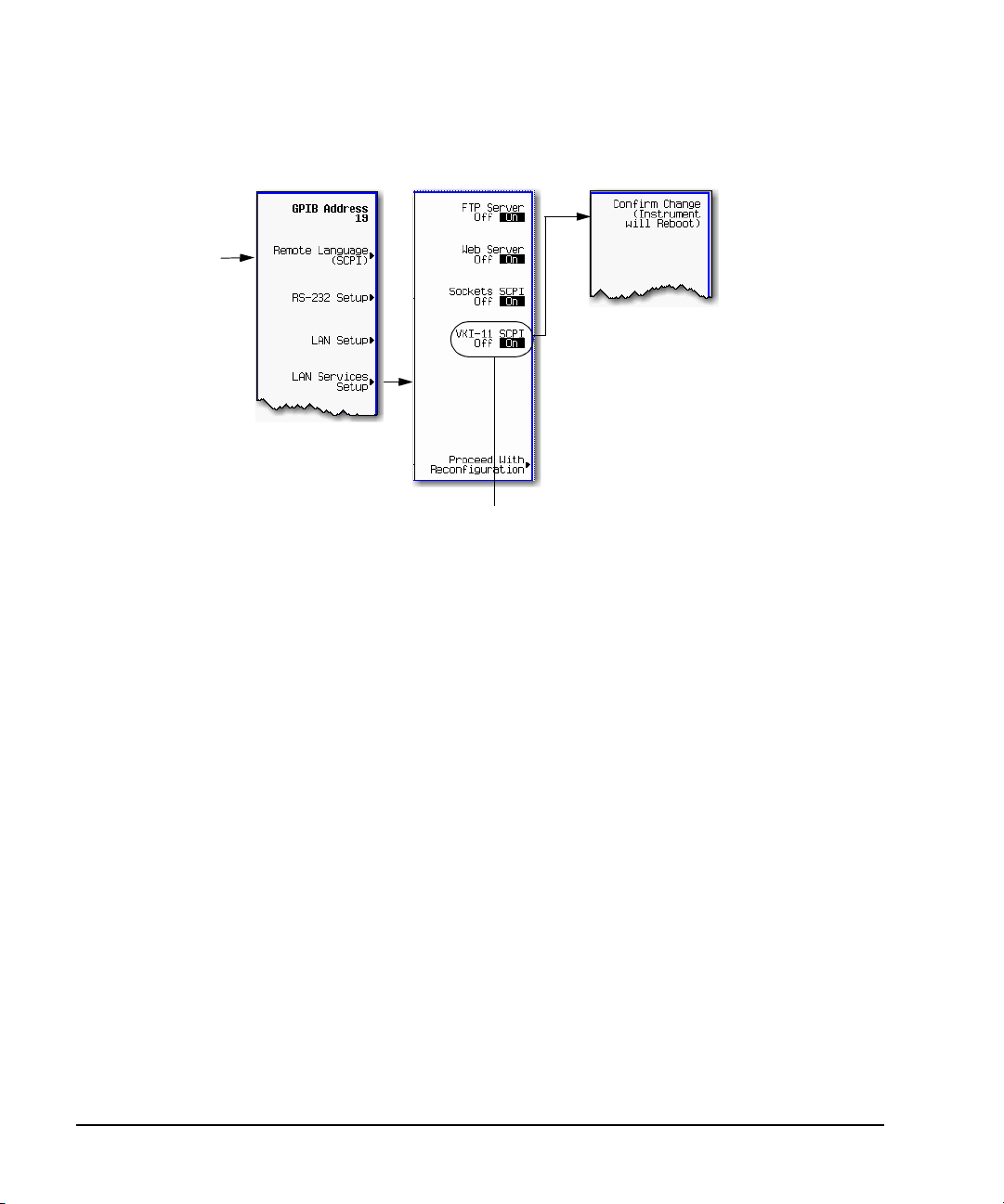
NOTE
T o communicate with the signal generator over the LAN, you must enable the VXI-11 SCPI service. Select VXI-11
until On is highlighted. (Default condition is On.)
For optimum performance, use a 100Base-T LAN cable to connect the signal generator to the LAN.
For details on each key, use the key help. For information describing the key help, refer to “Getting Help (Agilent MXG)” on page 18 and
the User’s Guide. For additional SCPI command information, refer to the SCPI Command Reference.
Utility > IO Config
Using LAN
Setting Up the LAN Interface
For LAN operation, the signal generator must be connected to the LAN, and an IP address must be
assigned to the signal generator either manually or by using DHCP client service. Your system
administrator can tell you which method to use. (Most modern LAN networks use DHCP.)
NOTE Verify that the signal generator is connected to the LAN using a 100Base-T LAN or 10Base-T
LAN cable.
Configuring the VXI-11 for LAN (Agilent MXG)
Agilent N518xA, E8663B, E44x8C, and E82x7D Signal Generators Programming Guide 29
Using IO Interfaces
NOTE
To communicate with the signal generator over the LAN, you must enable the VXI-11 SCPI service. Select VXI-11 until On is highlighted.
(Default condition is On.)
Use a 10Base-T LAN cable to connect the signal generator to the LAN.Where auto-negotiation is present, the ESG, PSG, or E8663B can
connect to 100Base-T LAN, but will communicate at 10Base-T speeds. For more information refer to http://www.ieee.org.
For details on each key, use the Key and Data Field
Reference. For additional SCPI comma nd
information, refer to the SCPI Command Reference.
Utility > GPIB/RS-232
LAN
Using LAN
Configuring the VXI-11 for LAN (ESG/PSG/E8663B)
Manual Configuration
The Hostname softkey is only available when LAN Config Manual DHCP is set to Manual.
To remotely access the signal generator from a different LAN subnet, you must also enter the subnet
mask and default gateway. See your system administrator for more information.
For more information on the manual configuration, refer to “Manually Configuring the Agilent MXG
LAN” on page 31 or to “Manually Configuring the ESG/PSG/E8663B LAN” on page 31.
30 Agilent N518xA, E8663B, E44x8C, and E82x7D Signal Generators Programming Guide

Manually Configuring the Agilent MXG LAN
For details on each key, use the key help (described in User’s Guide). For additional SCPI command information, refer to the SCPI
Command Reference.
Your hostname can be up to 20 characters long.
Utility > IO Config
SCPI commands:
:SYSTem:COMMunicate:LAN:CONFig MANual
:SYSTem:COMMunicate:LAN:CONFig?
For details on each key, use the Key and Data Field
Reference. For addition al SCPI co mmand info rmati on, refer
to the SCPI Command Reference.
The Hostname softkey is available only when LAN Config Manual DHCP is set to
Manual. Your hostname can be up to 20 characters long.
Utility > IO Config
SCPI commands:
:SYSTem:COMMunicate:LAN:CONFig MANual
:SYSTem:COMMunicate:LAN:CONFig?
Using IO Interfaces
Using LAN
Manually Configuring the ESG/PSG/E8663B LAN
Agilent N518xA, E8663B, E44x8C, and E82x7D Signal Generators Programming Guide 31

Using IO Interfaces
Using LAN
DHCP Configuration
If the DHCP server uses dynamic DNS to link the hostname with the assigned IP address, the
hostname may be used in place of the IP address. Otherwise, the hostname is not usable.
For more information on the DHCP configuration, refer to “Configuring the DHCP LAN (Agilent
MXG)” on page 33 or “Configuring the DHCP LAN (ESG/PSG/E8663B)” on page 33.
AUTO (DHCP/Auto-IP) Configuration (Agilent MXG)
DHCP and Auto-IP are used together to make automatic (AUTO) mode for IP configuration.
Automatic mode attempts DHCP first and then if that fails Auto- IP is used to detect a private
network. If neither is found, Manual is the final choice.
If the DHCP server uses dynamic DNS to link the hostname with the assigned IP address, the
hostname may be used in place of the IP address. Otherwise, the hostname is not usable.
Auto- IP provides automatic TCP/IP set- up for instruments on any manually configured networks.
For more information on the AUTO (DHCP/Auto-IP) configuration, refer to “Configuring the DHCP
LAN (Agilent MXG)” on page 33.
32 Agilent N518xA, E8663B, E44x8C, and E82x7D Signal Generators Programming Guide

Configuring the DHCP LAN (Agilent MXG)
For details on each key, use the key help (described in User’s Guide). For additional SCPI command information, refer to the SCPI
Command Reference.
AUTO (DHCP/Auto-IP): Request a new IP address in the following sequence: 1) from the DHCP (server-based
LAN), 2) Auto-IP (private network without a network administrator) or if neither is available, 3) Manual setting is
selected.
DHCP: Request a new IP address from the DHCP server each power cycle.
Confirming this action configures the signal generator as a DHCP client. In DHCP mode, the signal generator
will request a new IP address from the DHCP server upon rebooting to determine the assigned IP address.
Utility > IO Config
SCPI commands:
:SYSTem:COMMunicate:LAN:CONFig DHCP|AUTO
:SYSTem:COMMunicate:LAN:CONFig?
For details on each key, refer to the Key and Data Field
Reference. For additional SCPI c ommand information,
refer to the SCPI Command Referen c e.
NOTE
Use a 10Base-T LAN cable to connect the signal
generator to the LAN.
DHCP: Request a new IP address from the DHCP server each power cycle.
Confirming this action configures the signal generator as a DHCP client. In
DHCP mode, the signal generator will request a new IP address from the
DHCP server upon rebooting to determine the assigned IP address.
SCPI commands:
:SYSTem:COMMunicate:LAN:CONFig DHCP
:SYSTem:COMMunicate:LAN:CONFig?
Using IO Interfaces
Using LAN
Configuring the DHCP LAN (ESG/PSG/E8663B)
Agilent N518xA, E8663B, E44x8C, and E82x7D Signal Generators Programming Guide 33

Using IO Interfaces
Using LAN
Setting up Private LAN
You can connect the Agilent MXG, ESG, PSG or E8663B directly to a PC using a crossover cable. To
do this, you should either choose to set IP addresses of the PC and signal generator to differ only in
the last digit (example: PC’s IP: 1.1.1.1 and Signal generator’s IP: 1.1.1.2); or you can use the DHCP
feature or Auto- IP feature if your PC supports them. For more information go to www.agilent.com,
and search on the Connectivity Guide (E2094- 90009) or use the Agilent Connection Expert’s Help to
see the Connection Guide.
Verifying LAN Functionality
Verify the communications link between the computer and the signal generator remote file server
using the ping utility. Compare your ping response to those described in Table 2- 1 on page 35.
NOTE For additional information on troubleshooting your LAN connection, refer to “If You Have
Problems” on page 25 and to the Help in the Agilent IO Libraries and documentation for
LAN connections and problems.
From a UNIX
®
workstation, type (UNIX is a registered trademark of the Open Group):
ping <hostname or IP address> 64 10
where <hostname or IP address> is your instrument’s name or IP address, 64 is the packet size,
and 10 is the number of packets transmitted. Type man ping at the UNIX prompt for details on the
ping command.
®
From the MS- DOS
Command Prompt or Windows environment, type:
ping -n 10 <hostname or IP address>
where <hostname or IP address> is your instrument’s name or IP address and 10 is the number of
echo requests. Type ping at the command prompt for details on the ping command.
NOTE In DHCP mode, if the DHCP server uses dynamic DNS to link the hostname with the
assigned IP address, the hostname may be used in place of the IP address. Otherwise, the
hostname is not usable and you must use the IP address to communicate with the signal
generator over the LAN.
If You Have Problems
If you are experiencing problems with the LAN connection on the signal generator, verify the rear
panel LAN connector green LED is on.
MS- DOS, and Visual Basic are registered trademarks of Microsoft.
34 Agilent N518xA, E8663B, E44x8C, and E82x7D Signal Generators Programming Guide

Using IO Interfaces
Using LAN
For additional information on troubleshooting your LAN connection, refer to the Help in the Agilent
IO Libraries and documentation for LAN connections and problems.
Table 2-1 Ping Responses
Normal Response for UNIX A normal response to the ping command will be a total of 9 or 10 packets received with a
Normal Response for DOS or
Windows
Error Messages If error messages appear, then check the command syntax before continuing with
No Response If there is no response from a ping, no packets were received. Check that the typed address
minimal average round-trip time. The minimal average will be different from network to
network. LAN traffic will cause the round-trip time to vary widely.
A normal response to the ping command will be a total of 9 or 10 packets received if 10 echo
requests were specified.
troubleshooting. If the syntax is correct, resolve the error messages using your network
documentation or by consulting your network administrator.
If an unknown host error message appears, try using the IP address instead of the hostname.
Also, verify that the host name and IP address for the signal generator have been registered
by your IT administrator.
Check that the hostname and IP address are correctly entered in the node names database. To
do this, enter the nslookup <hostname> command from the command prompt.
or hostname matches the IP address or hostname assigned to the signal generator in the
System LAN Setup menu. For more information, refer to “Configuring the DHCP LAN (Agilent
MXG)” on page 33 or “Configuring the DHCP LAN (ESG/PSG/E8663B)” on page 33.
Ping each node along the route between your workstation and the signal generator, starting
with your workstation. If a node doesn’t respond, contact your IT administrator.
If the signal generator still does not respond to ping, you should suspect a hardware problem.
• Check the signal generator LAN connector lights
• Verify the hostname is not being used with DHCP addressing
Intermittent Response If you received 1 to 8 packets back, there maybe a problem with the network. In networks
with switches and bridges, the first few pings may be lost until these devices ‘learn’ the
location of hosts. Also, because the number of packets received depends on your network
traffic and integrity, the number might be different for your network. Problems of this nature
are best resolved by your IT department.
Using Interactive IO
Use the VISA Assistant utility available in the Agilent IO Libraries Suite to verify instrument
communication over the LAN interface. Refer to the section on the “IO Libraries and Programming
Languages” on page 5 for more information.
The Agilent IO Libraries Suite is supported on all platforms except Windows NT. If you are using
Windows NT, refer to section below on using the VISA Assistant to verify LAN communication. See
the section on “Windows NT and Agilent IO Libraries M (and Earlier)” on page 6 for more
information.
Agilent N518xA, E8663B, E44x8C, and E82x7D Signal Generators Programming Guide 35

Using IO Interfaces
Using LAN
NOTE The following sections are specific to Agilent IO Libraries versions M and earlier and apply
only to the Windows NT platform.
Using VISA Assistant
Use the VISA Assistant, available with the Agilent IO Library versions M and earlier, to communicate
with the signal generator over the LAN interface. However, you must manually configure the VISA
LAN client. Refer to the Help menu for instructions on configuring and running the VISA Assistant
program.
1. Run the IO Config program.
2. Click on TCPIP0 in the Available Interface Types text box.
3. Click the Configure button. Then Click OK to use the default settings.
4. Click on TCPIP0 in the Configured Interfaces text box.
5. Click Edit...
6. Click the Edit VISA Config... button.
7. Cli c k the Add device button.
8. Enter the TCPIP address of the signal generator. Leave the Device text box empty.
9. Click the OK button in this form and all subsequent forms to exit the IO Config program.
If You Have Problems
1. Verify the signal generator’s IP address is valid and that no other instrument is using the IP
address.
2. Switch between manual LAN configuration and DHCP using the front- panel LAN Config softkey and
run the ping program using the different IP addresses.
NOTE For Agilent IO Libraries versions M and earlier, you must manually configure the VISA LAN
client in the IO Config program if you want to use the VISA Assistant to verify LAN
configuration. Refer to the IO Libraries Installation Guide for information on configuring IO
interfaces. The IO Config program interface is shown in Figure 2- 4 on page 38.
36 Agilent N518xA, E8663B, E44x8C, and E82x7D Signal Generators Programming Guide

Using IO Interfaces
Using LAN
Figure 2-3 IO Config Form (Windows NT)
Check to see that the Default Protocol is set to Automatic.
1. Run the IO Config program
2. Click on TCPIP in the Configured Interfaces text box. If there is no TCPIP0 in the box, follow the
steps shown in the section “Using VISA Assistant” on page 36
3. Click the Edit button.
4. Click the radio button for AUTO (automatically detect protocol).
5. Click OK, OK to end the IO Config program.
Using VXI-11
The signal generator supports the LAN interface protocol described in the VXI- 11 standard. VXI- 11 is
an instrument control protocol based on Open Network Computing/Remote Procedure Call (ONC/RPC)
interfaces running over TCP/IP. It is intended to provide GBIB capabilities such as SRQ (Service
Request), status byte reading, and DCAS (Device Clear State) over a LAN interface. This protocol is a
good choice for migrating from GPIB to LAN as it has full Agilent VISA/SICL support.
NOTE It is recommended that the VXI-11 protocol be used for instrument communication over the
Agilent N518xA, E8663B, E44x8C, and E82x7D Signal Generators Programming Guide 37
LAN interface.

Using IO Interfaces
Using LAN
Configuring for VXI-11
The Agilent IO library has a program, IO Config, that is used to setup the computer/signal generator
interface for the VXI- 11 protocol. Download the latest version of the Agilent IO library from the
Agilent website. Refer to the Agilent IO library user manual, documentation, and Help menu for
information on running the IO Config program and configuring the VXI- 11 interface.
Use the IO Config program to configure the LAN client. Once the computer is configured for a LAN
client, you can use the VXI-11 protocol and the VISA library to send SCPI commands to the signal
generator over the LAN interface. Example programs for this protocol are included in “LAN
Programming Interface Examples” on page 101 of this programming guide.
NOTE To communicate with the signal generator over the LAN interface you must enable the
VXI- 11 SCPI service. For more information, refer to “Configuring the DHCP LAN (Agilent
MXG)” on page 33 and “Configuring the DHCP LAN (ESG/PSG/E8663B)” on page 33.
If you are using the Windows NT platform, refer to “Windows NT and Agilent IO Libraries M
(and Earlier)” on page 6 for information on using Agilent IO Libraries versions M or earlier
to configure the interface.
For Agilent IO library version J.01.0100, the “Identify devices at run- time” check box must be
unchecked. Refer to Figure 2- 4.
Figure 2-4 Show Devices Form (Agilent IO Library version J.01.0100)
38 Agilent N518xA, E8663B, E44x8C, and E82x7D Signal Generators Programming Guide

Using IO Interfaces
Using LAN
Using Sockets LAN
NOTE Users with Windows XP operating systems and newer can use this section to better
understand how to use the signal generator with port settings. For more information, refer to
the help software of the IO libraries being used.
Sockets LAN is a method used to communicate with the signal generator over the LAN interface
using the Transmission Control Protocol/Internet Protocol (TCP/IP). A socket is a fundamental
technology used for computer networking and allows applications to communicate using standard
mechanisms built into network hardware and operating systems. The method accesses a port on the
signal generator from which bidirectional communication with a network computer can be
established.
Sockets LAN can be described as an internet address that combines Internet Protocol (IP) with a
device port number and represents a single connection between two pieces of software. The socket
can be accessed using code libraries packaged with the computer operating system. Two common
versions of socket libraries are the Berkeley Sockets Library for UNIX systems and Winsock for
Microsoft operating systems.
Your signal generator implements a sockets Applications Programming Interface (API) that is
compatible with Berkeley socket for UNIX systems, and Winsock for Microsoft systems. The signal
generator is also compatible with other standard sockets APIs. The signal generator can be controlled
using SCPI commands that are output to a socket connection established in your program.
Before you can use sockets LAN, you must select the signal generator’s sockets port number to use:
• Standard mode. Available on port 5025. Use this port for simple programming.
• TELNET mode. The telnet SCPI service is available on port 5023.
NOTE For backward compatibility, on the E8663B, ESG, and PSG, the signal generator also accepts
An example using sockets LAN is given in “LAN Programming Interface Examples” on page 101 of
this programming guide.
references to the Telnet SCPI service at port 7777 and sockets SCPI service at port 7778.
Ports 7777 and 7778 are disabled on the Agilent MXG.
Using Telnet LAN
Telnet provides a means of communicating with the signal generator over the LAN. The Telnet client,
run on a LAN connected computer, will create a login session on the signal generator. A connection,
established between computer and signal generator, generates a user interface display screen with
SCPI> prompts on the command line.
Using the Telnet protocol to send commands to the signal generator is similar to communicating with
the signal generator over GPIB. You establish a connection with the signal generator and then send
or receive information using SCPI commands. Communication is interactive: one command at a time.
Agilent N518xA, E8663B, E44x8C, and E82x7D Signal Generators Programming Guide 39

Using IO Interfaces
Using LAN
NOTE The Windows 2000 operating systems use a command prompt style interface for the Telnet
client. Refer to the Figure 2- 7 on page 42 for an example of this interface.
Windows XP operating systems and newer can use this section to better understand how to
use the signal generator with port settings. For more information, refer to the help software
of the IO libraries being used.
The following telnet LAN connections are discussed:
• “Using Telnet and MS-DOS Command Prompt” on page 40
• “Using Telnet On a PC With a Host/Port Setting Menu GUI” on page 41
• “Using Telnet On Windows 2000” on page 41
• “The Standard UNIX Telnet Command” on page 42
A Telnet example is provided in “Unix Telnet Example” on page 42.
Using Telnet and MS-DOS Command Prompt
1. On your PC, click Start > Programs > Command Prompt.
2. At the command prompt, type in telnet.
3. Press the Enter key. The Telnet display screen will be displayed.
4. Click on the Connect menu then select Remote System. A connection form (Figure 2-5) is displayed.
Figure 2-5 Connect Form (Agilent IO Library version J.01.0100)
5. Enter the hostname, port number, and Te r m Typ e then click Connect.
•Host Name−IP address or hostname
•Port−5023
•Term Type−vt100
6. At the SCPI> prompt, enter SCPI commands. Refer to Figure 2-6 on page 41.
7. To signal device clear, press Ctrl-C on your keyboard.
8. Select Exit from the Connect menu and type exit at the command prompt to end the Telnet
session.
40 Agilent N518xA, E8663B, E44x8C, and E82x7D Signal Generators Programming Guide

Using IO Interfaces
Using LAN
Using Telnet On a PC With a Host/Port Setting Menu GUI
1. On your PC, click Start > Run.
2. Type telnet then click the OK button. The Telnet connection screen will be displayed.
3. Click on the Connect menu then select Remote System. A connection form is displayed. See Figure
2- 5.
4. Enter the hostname, port number, and Te r m Typ e then click Connect.
•Host Name−signal generator’s IP address or hostname
•Port−5023
•Term Type−vt100
5. At the SCPI> prompt, enter SCPI commands. Refer to Figure 2-6 on page 41.
6. To signal device clear, press Ctrl-C.
7. Sel ect Exit from the Connect menu to end the Telnet session.
Figure 2-6 Telnet Window (Windows 2000)
Using Telnet On Windows 2000
1. On your PC, click Start > Run.
2. Type telnet in the run text box, then click the OK button. The Telnet connection screen will be
displayed. See Figure 2- 7 on page 42 (Windows 2000).
3. Type open at the prompt and then press the Enter key. The prompt will change to (to).
4. At the (to) prompt, enter the signal generator’s IP address followed by a space and 5023, which
is the Telnet port associated with the signal generator.
5. At the SCPI> prompt, enter SCPI commands. Refer to commands shown in Figure 2- 6 on
page 41.
6. To escape from the SCPI> session type Ctrl-].
7. T ype quit at the prompt to end the Telnet session.
Agilent N518xA, E8663B, E44x8C, and E82x7D Signal Generators Programming Guide 41

Using IO Interfaces
Using LAN
Figure 2-7 Telnet 2000 Window
The Standard UNIX Telnet Command
Synopsis
telnet [host [port]]
Description
This command is used to communicate with another host using the Telnet protocol. When the
command telnet is invoked with host or port arguments, a connection is opened to the host, and
input is sent from the user to the host.
Options and Parameters
The command telnet operates in character-at- a- time or line- by-line mode. In line- by-line mode,
typed text is echoed to the screen. When the line is completed (by pressing the Enter key), the text
line is sent to host. In character- at- a- time mode, text is echoed to the screen and sent to host as it
is typed. At the UNIX prompt, type man telnet to view the options and parameters available with
the telnet command.
NOTE If your Telnet connection is in line-by- line mode, there is no local echo. This means you
cannot see the characters you are typing until you press the Enter key. To remedy this,
change your Telnet connection to character- by- character mode. Escape out of Telnet, and at
the telnet> prompt, type mode char. If this does not work, consult your Telnet program's
documentation.
Unix Telnet Example
To connect to the instrument with host name myInstrument and port number 5023, enter the
following command on the command line: telnet myInstrument 5023.
42 Agilent N518xA, E8663B, E44x8C, and E82x7D Signal Generators Programming Guide

Using IO Interfaces
Using LAN
When you connect to the signal generator, the UNIX window will display a welcome message and a
SCPI command prompt. The instrument is now ready to accept your SCPI commands. As you type
SCPI commands, query results appear on the next line. When you are done, break the Telnet
connection using an escape character. For example, Ctrl-],where the control key and the ] are
pressed at the same time. The following example shows Telnet commands:
$ telnet myinstrument 5023
Trying....
Connected to signal generator
Escape character is ‘^]’.
Agilent Technologies, E44xx SN-US00000001
Firmware:
Hostname: your instrument
IP :xxx.xx.xxx.xxx
SCPI>
Using FTP
FTP allows users to transfer files between the signal generator and any computer connected to the
LAN. For example, you can use FTP to download instrument screen images to a computer. When
logged onto the signal generator with the FTP command, the signal generator’s file structure can be
accessed. Figure 2-8 shows the FTP interface and lists the directories in the signal generator’s user
level directory.
NOTE File access is limited to the signal generator’s /user directory.
Agilent N518xA, E8663B, E44x8C, and E82x7D Signal Generators Programming Guide 43

Using IO Interfaces
Using LAN
Figure 2-8 FTP Screen
The following steps outline a sample FTP session from the MS-DOS Command Prompt:
1. On the PC click Start > Programs > Command Prompt.
2. At the command prompt enter:
ftp < IP address > or < hostname >
3. At the user name prompt, press enter.
4. At the password prompt, press enter.
You are now in the signal generator’s user directory. Typing help at the command prompt will
show you the FTP commands that are available on your system.
5. Type quit or bye to end your FTP session.
6. Type exit to end the command prompt session.
44 Agilent N518xA, E8663B, E44x8C, and E82x7D Signal Generators Programming Guide

Using RS-232 (ESG, PSG, and E8663B Only)
Using IO Interfaces
Using RS-232 (ESG, PSG, and E8663B Only)
NOTE The RS- 232 serial interface is available on the ESG signal generators.
The PSG and E8663B’s AUXILIARY INTERFACE connector is compatible with ANSI/EIA232
(RS- 232) serial connection but GPIB and LAN are recommended for making faster
measurements and when downloading files. Refer to the User’s Guide.
The RS- 232 serial interface can be used to communicate with the signal generator. The RS-232
connection was once standard on most PCs but has now been replaced by USB. RS-232 can be
connected to the signal generator’s rear- panel connector using the cable described in Table 2- 2 on
page 47. Many functions provided by GPIB, with the exception of indefinite blocks, parallel polling,
serial polling, GET, non-SCPI remote languages, SRQ, and remote mode are available using the
RS- 232 interface.
The serial port sends and receives data one bit at a time, therefore RS- 232 communication is slow.
The data transmitted and received is usually in ASCII format with SCPI commands being sent to the
signal generator and ASCII data returned.
The following sections contain information on selecting and connecting IO libraries and RS- 232
interface hardware on the signal generator to a computer’s RS- 232 connector.
• “Selecting IO Libraries for RS- 232” on page 45
• “Setting Up the RS- 232 Interface” on page 46
• “Verifying RS-232 Functionality” on page 48
Selecting IO Libraries for RS-232
The IO libraries can be downloaded from the National Instrument website, http://www.ni.com, or
Agilent’s website, http://www.agilent.com. The following is a discussion on these libraries.
CAUTION Because of the potential for portability problems, running Agilent SICL without the
VISA overlay is not recommended by Agilent Technologies.
HP Basic The HP Basic language has an extensive IO library that can be used to control the
VISA VISA is an IO library used to develop IO applications and instrument drivers that
NI- 488.2 NI- 488.2 IO libraries can be used to develop applications for the RS- 232 interface.
Agilent N518xA, E8663B, E44x8C, and E82x7D Signal Generators Programming Guide 45
signal generator over the RS- 232 interface. This library has many low level
functions that can be used in BASIC applications to control the signal generator
over the RS- 232 interface.
comply with industry standards. It is recommended that the VISA library be used
for programming the signal generator. The NI-VISA and Agilent VISA libraries are
similar implementations of VISA and have the same commands, syntax, and
functions. The differences are in the lower level IO libraries used to communicate
over the RS- 232; NI- 488.2 and SICL respectively.
See National Instrument’s website for information on NI- 488.2.

Using IO Interfaces
For details on each key, use the key help (described in User’s Guide). For additional SCPI command information, refer to the SCPI
Command Reference.
Select a baud
rate of 9600.
SCPI commands:
:SYSTem:COMMunicate:SERial:BAUD <number>
:SYSTem:COMMunicate:SERial:BAUD?
Using RS-232 (ESG, PSG, and E8663B Only)
SICL Agilent SICL can be used to develop applications for the RS- 232 interface. See
Agilent’s website for information on SICL.
Setting Up the RS-232 Interface
1. Setting the RS- 232 Interface Baud Rate (ESG/PSG/E8663B)
NOTE Configure your computer to use baud rates 57600 or lower only. Select the signal generator’s
baud rate to match the baud rate of your computer or UNIX workstation or adjust the baud
rate settings on your computer to match the baud rate setting of the signal generator.
The default baud rate for VISA is 9600. This baud rate can be changed with the
“VI_ATTR_ASRL_BAUD” VISA attribute.
46 Agilent N518xA, E8663B, E44x8C, and E82x7D Signal Generators Programming Guide

Using RS-232 (ESG, PSG, and E8663B Only)
For details on each key, use the key help (described in User’s Guide). For additional SCPI command information, refer to the SCPI
Command Reference.
Toggle RS-232 Echo Off On until Off is
highlighted. Selecting On echo es or retu rn s
characters sent to the signal generator and
prints them to the display.
SCPI commands:
:SYSTem:COMMunicate:SERial:ECHO ON|OFF
:SYSTem:COMMunicate:SERial:ECHO?
Using IO Interfaces
2. Setting the RS- 232 Echo Softkey
3. Connect an RS- 232 cable from the computer’s serial connector to the ESG signal generator’s
RS-232 connector or the PSG or E8663B’s AUXILIARY INTERFACE connector. Refer to Table 2- 2 for
RS- 232 cable information.
Table 2-2 RS-232 Serial Interface Cable
Quantity Description Agilent Part Number
1 Serial RS- 232 cable 9- pin (male) to 9- pin (female) 8120- 6188
NOTE Any 9 pin (male) to 9 pin (female) straight- through cable that directly wires pins 2, 3, 5, 7,
and 8 may be used.
Agilent N518xA, E8663B, E44x8C, and E82x7D Signal Generators Programming Guide 47

Using IO Interfaces
Using RS-232 (ESG, PSG, and E8663B Only)
Verifying RS-232 Functionality
You can use the HyperTerminal program available on your computer to verify the RS- 232 interface
functionality. To run the HyperTerminal program, connect the RS- 232 cable between the computer
and the signal generator and perform the following steps:
1. On the PC click Start > Programs > Accessories > Communications > HyperTerminal.
2. Select HyperTerminal.
3. Enter a name for the session in the text box and select an icon.
4. Select COM1 (COM2 can be used if COM1 is unavailable).
5. In the COM1 (or COM2, if selected) properties, set the following parameters:
• Bits per second: 9600 must match signal generator’s baud rate; for more information, refer to
“Setting Up the RS- 232 Interface” on page 46.
• Data bits: 8
• Parity: None
• Stop bits: 1
• Flow Control: None
NOTE Flow control, via the RTS line, is driven by the signal generator. For the purposes of this
verification, the controller (PC) can ignore this if flow control is set to None. However, to
control the signal generator programmatically or download files to the signal generator,
you must enable RTS- CTS (hardware) flow control on the controller. Note that only the
RTS line is currently used.
Software Flow Control using XON and XOFF is not supported. Only RTS- CTS hardware
flow is supported.
6. Go to the HyperTerminal window and select File > Properties.
7. Go t o Settings > Emulation and select VT100.
8. Leave the Backscroll buffer lines set to the default value.
9. Go to Settings > ASCII Setup.
10. Check the first two boxes and leave the other boxes as default values.
Once the connection is established, enter the SCPI command *IDN? followed by <Ctrl j> in the
HyperTerminal window. The <Ctrl j> is the new line character (on the keyboard press the Cntrl key
and the j key simultaneously).
The signal generator should return a string similar to the following, depending on model:
Agilent Technologies <instrument model name and number>, US40000001,C.02.00
48 Agilent N518xA, E8663B, E44x8C, and E82x7D Signal Generators Programming Guide

Using RS-232 (ESG, PSG, and E8663B Only)
Using IO Interfaces
Character Format Parameters
The signal generator uses the following character format parameters when communicating via RS- 232:
• Character Length: Eight data bits are used for each character, excluding start, stop, and parity
bits.
• Parity Enable: Parity is disabled (absent) for each character.
• Stop Bits: One stop bit is included with each character.
If You Have Problems
1. Verify that the baud rate, parity, and stop bits are the same for the computer and signal
generator.
2. Verify that the RS- 232 cable is identical to the cable specified in Table 2- 2.
3. Verify that the application is using the correct computer COM port and that the RS- 232 cable is
properly connected to that port.
4. Verify that the controller’s flow control is set to RTS- CTS.
Agilent N518xA, E8663B, E44x8C, and E82x7D Signal Generators Programming Guide 49

Using IO Interfaces
RS-232 Programming Interface Examples
RS-232 Programming Interface Examples
NOTE The portions of the programming examples discussed in this section are taken from the full
text of these programs that can be found in Chapter 3, “Programming Examples.”
• “Interface Check Using HP BASIC” on page 50
• “Interface Check Using VISA and C” on page 51
• “Queries Using HP Basic and RS- 232” on page 51
• “Queries for RS-232 Using VISA and C” on page 52
Before Using the Examples
Before using the examples: On the signal generator select the following settings:
• Baud Rate - 9600 must match computer’s baud rate
• RS- 232 Echo - Off
The following sections contain HP Basic and C lines of programming removed from the programming
interface examples in Chapter 3, Programming Examples,, these portions of programming demonstrate
the important features to consider when developing programming for use with the RS- 232 interface.
NOTE For RS- 232 programming examples, refer to “RS- 232 Programming Interface Examples
(ESG/PSG/E8663B Only)” on page 131.
Interface Check Using HP BASIC
This portion of the example program “Interface Check Using HP BASIC” on page 50, causes the signal
generator to perform an instrument reset. The SCPI command *RST will place the signal generator
into a pre- defined state.
The serial interface address for the signal generator in this example is 9. The serial port used is
COM1 (Serial A on some computers). Refer to “Using RS-232 (ESG, PSG, and E8663B Only)” on
page 45 for more information.
The following program example is available on the signal generator’s Documentation CD- ROM as
rs232ex1.txt. For the full text of this program, refer to “Interface Check Using HP BASIC” on
page 131 or to the signal generator’s documentation CD-ROM.
170 CONTROL 9,0;1 ! Resets the RS-232 interface
180 CONTROL 9,3;9600 ! Sets the baud rate to match the sig gen
190 STATUS 9,4;Stat ! Reads the value of register 4
200 Num=BINAND(Stat,7) ! Gets the AND value
210 CONTROL 9,4;Num ! Sets parity to NONE
220 OUTPUT 9;"*RST" ! Outputs reset to the sig gen
50 Agilent N518xA, E8663B, E44x8C, and E82x7D Signal Generators Programming Guide

RS-232 Programming Interface Examples
Using IO Interfaces
Interface Check Using VISA and C
This portion of the example program “Interface Check Using VISA and C” on page 51, uses VISA
library functions to communicate with the signal generator. The program verifies that the RS- 232
connections and interface are functional. In this example the COM2 port is used. The serial port is
referred to in the VISA library as ‘ASRL1’ or ‘ASRL2’ depending on the computer serial port you are
using.
The following program example is available on the signal generator Documentation CD- ROM as
rs232ex1.cpp. For the full text of this program, refer to “Interface Check Using VISA and C” on
page 132 or to the signal generator’s documentation CD-ROM.
int baud=9600;// Set baud rate to 9600
ViSession defaultRM, vi;// Declares a variable of type ViSession
// for instrument communication on COM 2 port
ViStatus viStatus = 0;
// Opens session to RS-232 device at serial port 2
viStatus=viOpenDefaultRM(&defaultRM);
viStatus=viOpen(defaultRM, "ASRL2::INSTR", VI_NULL, VI_NULL, &vi);
viStatus=viEnableEvent(vi, VI_EVENT_IO_COMPLETION, VI_QUEUE,VI_NULL);
viClear(vi);// Sends device clear command
// Set attributes for the session
viSetAttribute(vi,VI_ATTR_ASRL_BAUD,baud);
viSetAttribute(vi,VI_ATTR_ASRL_DATA_BITS,8);
Queries Using HP Basic and RS-232
This portion of the example program “Queries Using HP Basic and RS- 232” on page 51, example
program demonstrates signal generator query commands over RS- 232. Query commands are of the
type *IDN? and are identified by the question mark that follows the mnemonic.
Start HP Basic, type in the following commands, and then RUN the program:
The following program example is available on the signal generator Documentation CD- ROM as
rs232ex2.txt. For the full text of this program, refer to “Queries Using HP Basic and RS- 232” on
page 134 or to the signal generator’s documentation CD-ROM.
190 OUTPUT 9;"*IDN?" ! Querys the sig gen ID
200 ENTER 9;Str$ ! Reads the ID
210 WAIT 2 ! Waits 2 seconds
220 PRINT "ID =",Str$ ! Prints ID to the screen
230 OUTPUT 9;"POW:AMPL -5 dbm" ! Sets the the power level to -5 dbm
240 OUTPUT 9;"POW?" ! Querys the power level of the sig gen
Agilent N518xA, E8663B, E44x8C, and E82x7D Signal Generators Programming Guide 51

Using IO Interfaces
RS-232 Programming Interface Examples
Queries for RS-232 Using VISA and C
This portion of the example program “Queries for RS- 232 Using VISA and C” on page 52, uses VISA
library functions to communicate with the signal generator. The program verifies that the RS- 232
connections and interface are functional.
The following program example is available on the signal generator Documentation CD- ROM as
rs232ex2.cpp. For the full text of this program, refer to “Queries for RS- 232 Using VISA and C” on
page 135 or to the signal generator’s documentation CD-ROM.
status = viOpenDefaultRM(&defaultRM);// Initializes the system
// Open communication with Serial Port 2
status = viOpen(defaultRM, "ASRL2::INSTR", VI_NULL, VI_NULL, &instr);
52 Agilent N518xA, E8663B, E44x8C, and E82x7D Signal Generators Programming Guide

Using IO Interfaces
Using USB (Agilent MXG)
Using USB (Agilent MXG)
CAUTION USB cables are not industrial graded and potentially allows data loss in noisy
environments.
USB cables do not have a latching mechanism and the cables can be pulled out of the
PC or instrument relatively easily.
The maximum length for USB cables is 30 m, including the use of inline repeaters.
NOTE The USB interface is available only on the Agilent MXG signal generator.
The Agilent MXG’s USB 2.0 interface supports USBTMC or USBTMC- USB488 specifications.
For more information on connecting instruments to the USB, refer to the Agilent Connection
Expert in the Agilent IO Libraries Help.
USB 2.0 connectors can be used to communicate with the signal generator. The N5181A/82A is
equipped with a Mini- B 5 pin rear panel connector (device USB). Use a Type- A to Mini- USB 5 pin
cable to connect the signal generator to the computer (Refer to “Setting Up the USB Interface” on
page 55). Connect the Type-A front panel connector (host USB) can be used to connect a mouse, a
keyboard, or a USB 1.1/2.0 flash drive (USB media). (Refer to the User’s Guide.) ARB waveform
encryption of proprietary information is supported. Many functions provided by GPIB, including GET,
non- SCPI remote languages, and remote mode are available using the USB interface.
NOTE For a list of compatible flash drives to use with the USB external interface. Refer to
http://www.agilent.com/find/mxg.
Do not use the Type A front panel USB to connect to a computer.
The following sections contain information on selecting and connecting I/O libraries and the USB
interface that are required to remotely program the signal generator via computer and combining
those choices with one of several possible USB interface protocols.
• “Selecting I/O Libraries for USB” on page 54
• “Setting Up the USB Interface” on page 55
• “Verifying USB Functionality” on page 56
Agilent N518xA, E8663B, E44x8C, and E82x7D Signal Generators Programming Guide 53

Using IO Interfaces
Using USB (Agilent MXG)
Selecting I/O Libraries for USB
CAUTION The Agilent MXG’s USB interface requires Agilent IO Libraries Suite 14.1 or newer to
run properly. For more information on connecting instruments to the USB, refer to the
Agilent Connection Expert in the Agilent IO Libraries Help.
The I/O libraries can be downloaded from the National Instrument website, http://www.ni.com, or
Agilent’s website, http://www.agilent.com. The following is a discussion on these libraries.
NOTE I/O applications such as IVI- COM or VXIplug&play can be used in place of VISA.
VISA VISA is an I/O library used to develop I/O applications and instrument drivers
that comply with industry standards. It is recommended that the VISA library be
used for programming the signal generator. The NI- VISA and Agilent VISA
libraries are similar implementations of VISA and have the same commands,
syntax, and functions. The differences are in the lower level I/O libraries used to
communicate over the USB; NI- 488.2 and SICL respectively.
NI- 488.2 NI- 488.2 I/O libraries can be used to develop applications for the USB interface.
SICL Agilent SICL can be used to develop applications for the USB interface. See
See National Instrument’s website for information on NI- 488.2.
Agilent’s website for information on SICL.
CAUTION Because of the potential for portability problems, running Agilent SICL without the
VISA overlay is not recommended by Agilent Technologies.
54 Agilent N518xA, E8663B, E44x8C, and E82x7D Signal Generators Programming Guide

Using IO Interfaces
Using USB (Agilent MXG)
Setting Up the USB Interface
Rear Panel Interface (Mini–B 5 pin)
To use USB, connect the USB cable (Refer to Table 2- 3, “USB Interface Cable,” on page 55, for USB
cable information.) between the computer and the signal generator’s rear panel Mini- B 5- pin USB
connector.
Ta b l e 2 -3 U SB In te rf a ce C a b l e
Quantity Description Agilent Part Number
1 USB cable Mini- B 5 pin to Type- A 82357- 61601
Front Panel USB (Type–A)
For details on using the front panel USB (Type- A) and the front panel USB Media operation, refer to
the User’s Guide.
Using the Internal Storage and USB Media (Non-volatile Memories)
For details on using the internal storage and the front panel USB Media operation, refer to the User’s
Guide.
Agilent N518xA, E8663B, E44x8C, and E82x7D Signal Generators Programming Guide 55

Using IO Interfaces
Using USB (Agilent MXG)
Verifying USB Functionality
Mini-B 5 Pin Rear Panel Connector
NOTE For information on verifying your Mini- B 5 pin USB (rear panel) functionality, refer to the
Agilent Connection Expert in the Agilent IO Libraries Help. The Agilent IO libraries are
included with your signal generator or Agilent GPIB interface board, or they can be
downloaded from the Agilent website: http://www.agilent.com.
Type-A Front Panel USB Connector
For details on using the front panel USB (Type- A) and the front panel USB Media operation, refer to
the User’s Guide.
56 Agilent N518xA, E8663B, E44x8C, and E82x7D Signal Generators Programming Guide

3 Programming Examples
• “Using the Programming Interface Examples” on page 58
• “GPIB Programming Interface Examples” on page 62
• “LAN Programming Interface Examples” on page 101
• “RS-232 Programming Interface Examples (ESG/PSG/E8663B Only)” on page 131
Agilent N518xA, E8663B, E44x8C, and E82x7D Signal Generators Programming Guide 57

Programming Examples
Using the Programming Interface Examples
Using the Programming Interface Examples
The programming examples for remote control of the signal generator use the GPIB, LAN, and
RS- 232 interfaces and demonstrate instrument control using different IO libraries and programming
languages. Many of the example programs in this chapter are interactive; the user will be prompted
to perform certain actions or verify signal generator operation or functionality. Example programs are
written in the following languages:
HP Basic C#
C/C++ Microsoft Visual Basic 6.0
Java MATLAB
Perl
These example programs are also available on the signal generator Documentation CD- ROM, enabling
you to cut and paste the examples into a text editor.
NOTE The example programs set the signal generator into remote mode; front panel keys, except
the Agilent MXG Local/Esc/Cancel or the ESG, PSG, and E8663B’s Local key, are disabled.
Press the Agilent MXG Local/Esc/Cancel or the ESG, PSG, and E8663B’s Local key to revert to
manual operation.
To have the signal generator’s front panel update with changes caused by remote operations, enable
the signal generator’s Update in Remote function.
NOTE The Update in Remote function will slow test execution. For faster test execution, disable the
Update in Remote function. (For more information, refer to or “Configuring the Display for
Remote Command Setups (Agilent MXG)” on page 17.) or “Configuring the Display for
Remote Command Setups (ESG/PSG/E8663B)” on page 17.
Programming Examples Development Environment
The C/C++ examples were written using an IBM- compatible personal computer (PC), configured as
follows:
•Pentium® processor (Pentium is a registered trademark of Intel Corporation.)
• Windows NT 4.0 operating system or later
• C/C++ programming language with the Microsoft Visual C++ 6.0 IDE
• National Instruments PCI- GPIB interface card or Agilent GPIB interface card
• National Instruments VISA Library or Agilent VISA library
• COM1 or COM2 serial port available
•LAN interface card
The HP Basic examples were run on a UNIX 700 series workstation.
58 Agilent N518xA, E8663B, E44x8C, and E82x7D Signal Generators Programming Guide

Using the Programming Interface Examples
Programming Examples
Running C++ Programs
When using Microsoft Visual C++ 6.0 to run the example programs, include the following files in your
project.
When using the VISA library:
• add the visa32.lib file to the Resource Files
• add the visa.h file to the Header Files
When using the NI- 488.2 library:
• add the GPIB-32.OBJ file to the Resource Files
• add the windows.h file to the Header Files
• add the Deci- 32.h file to the Header Files
For information on the NI- 488.2 library and file requirements refer to the National Instrument
website. For information on the VISA library see the Agilent website or National Instrument’s
website.
NOTE To communicate with the signal generator over the LAN interface you must enable the
VXI- 11 SCPI service. For more information, refer to “Configuring the DHCP LAN (Agilent
MXG)” on page 33 and “Configuring the VXI-11 for LAN (ESG/PSG/E8663B)” on page 30.
C/C++ Examples
• “Interface Check for GPIB Using VISA and C” on page 68
• “Queries for RS-232 Using VISA and C” on page 135
• “Local Lockout Using NI-488.2 and C++” on page 71
• “Queries Using NI-488.2 and Visual C++” on page 73
• “Queries for GPIB Using VISA and C” on page 75
• “Generating a CW Signal Using VISA and C” on page 77
• “Generating an Externally Applied AC- Coupled FM Signal Using VISA and C” on page 79
• “Generating an Internal FM Signal Using VISA and C” on page 81
• “Generating a Step- Swept Signal Using VISA and C++” on page 83
• “Reading the Data Questionable Status Register Using VISA and C” on page 90
• “Reading the Service Request Interrupt (SRQ) Using VISA and C” on page 94
• “VXI- 11 Programming Using SICL and C++” on page 102
• “VXI- 11 Programming Using VISA and C++” on page 103
• “Sockets LAN Programming and C” on page 105
• “Interface Check Using VISA and C” on page 132
• “Queries for RS-232 Using VISA and C” on page 135
Agilent N518xA, E8663B, E44x8C, and E82x7D Signal Generators Programming Guide 59

Programming Examples
Using the Programming Interface Examples
Running C# Examples
To run the example program State_Files.cs on page 326, you must have the .NET framework installed
on your computer. You must also have the Agilent IO Libraries installed on your computer. The .NET
framework can be downloaded from the Microsoft website. For more information on running C#
programs using .NET framework, see Chapter 6.
NOTE To communicate with the signal generator over the LAN interface you must enable the
VXI- 11 SCPI service. For more information, refer to “Configuring the VXI- 11 for LAN
(Agilent MXG)” on page 29 and “Configuring the VXI- 11 for LAN (ESG/PSG/E8663B)” on
page 30.
Running Basic Examples
The BASIC programming interface examples provided in this chapter use either HP Basic or Visual
Basic 6.0 languages.
Visual Basic 6.0 Programming Examples
To run the example programs written in Visual Basic 6.0 you must include references to the IO
Libraries. For more information on VISA and IO libraries, refer to the Agilent VISA User’s Manual,
available on Agilent’s website: http://www.agilent.com. In the Visual Basic IDE (Integrated
Development Environment) go to Project–References and place a check mark on the following
references:
• Agilent VISA COM Resource Manager 1.0
•VISA COM 1.0 Type Library
NOTE If you want to use VISA functions such as viWrite, then you must add the visa32.bas module
The signal generator’s VXI- 11 SCPI service must be on before you can run the Download Visual Basic
6.0 programming example.
NOTE To communicate with the signal generator over the LAN interface you must enable the
60 Agilent N518xA, E8663B, E44x8C, and E82x7D Signal Generators Programming Guide
to your Visual Basic project.
VXI- 11 SCPI service. For more information, refer to “Configuring the VXI- 11 for LAN
(Agilent MXG)” on page 29 and “Configuring the VXI- 11 for LAN (ESG/PSG/E8663B)” on
page 30.

Using the Programming Interface Examples
You can start a new Standard EXE project and add the required references. Once the required
references are included, you can copy the example programs into your project and add a command
button to Form1 that will call the program.
The example Visual Basic 6.0 programs are available on the signal generator Documentation CD- ROM,
enabling you to cut and paste the examples into your project.
Visual Basic Examples
The Visual Basic examples enable the use of waveform files and are located in Chapter 5.
• “Creating I/Q Data—Little Endian Order” on page 262
• “Downloading I/Q Data” on page 265
HP Basic Examples
• “Interface Check using HP Basic and GPIB” on page 66
• “Local Lockout Using HP Basic and GPIB” on page 69
• “Queries Using HP Basic and GPIB” on page 72
• “Queries Using HP Basic and RS- 232” on page 134
• “Using 8757D Pass-Thru Commands (PSG with Option 007 Only)” on page 98
Programming Examples
Running Java Examples
The Java program “Sockets LAN Programming Using Java” on page 128, connects to the signal
generator via sockets LAN. This program requires Java version 1.1 or later be installed on your PC.
For more information on sockets LAN programming with Java, refer to “Sockets LAN Programming
Using Java” on page 128.
Running MATLAB Examples
For information regarding programming examples and files required to create and play waveform
files, refer to Chapter 5.
NOTE To communicate with the signal generator over the LAN interface you must enable the
VXI- 11 SCPI service. For more information, refer to “Configuring the VXI- 11 for LAN
(Agilent MXG)” on page 29 and “Configuring the VXI- 11 for LAN (ESG/PSG/E8663B)” on
page 30.
Running Perl Examples
The Perl example “Sockets LAN Programming Using PERL” on page 130, uses PERL script to control
the signal generator over the sockets LAN interface.
Agilent N518xA, E8663B, E44x8C, and E82x7D Signal Generators Programming Guide 61

Programming Examples
Using GPIB
Using GPIB
GPIB enables instruments to be connected together and controlled by a computer. GPIB and its
associated interface operations are defined in the ANSI/IEEE Standard 488.1- 1987 and ANSI/IEEE
Standard 488.2- 1992. See the IEEE website, http://www.ieee.org, for details on these standards.
The following sections contain information for installing a GPIB interface card or NI- GPIB interface
card for your PC or UNIX-based system.
• “Installing the GPIB Interface Card” on page 62
For more information on setting up a GPIB interface card or NI- GPIB interface card, refer to:
• “Set Up the GPIB Interface” on page 24
• “Verify GPIB Functionality” on page 25
NOTE You can also connect GPIB instruments to a PC USB port using the Agilent 82357A
USB/GPIB Interface Converter, which eliminates the need for a GPIB card. For more
information, go to http://www.agilent.com/find/gpib.
Installing the GPIB Interface Card
Refer to “Installing the GPIB Interface” on page 22.
GPIB Programming Interface Examples
• “Interface Check using HP Basic and GPIB” on page 66
• “Interface Check Using NI- 488.2 and C++” on page 67
• “Interface Check for GPIB Using VISA and C” on page 68
• “Local Lockout Using HP Basic and GPIB” on page 69
• “Local Lockout Using NI-488.2 and C++” on page 71
• “Queries Using HP Basic and GPIB” on page 72
• “Queries Using NI-488.2 and Visual C++” on page 73
• “Queries for GPIB Using VISA and C” on page 75
• “Generating a CW Signal Using VISA and C” on page 77
• “Generating an Externally Applied AC- Coupled FM Signal Using VISA and C” on page 79
• “Generating an Internal FM Signal Using VISA and C” on page 81
• “Generating a Step- Swept Signal Using VISA and C++” on page 83
• “Generating a Swept Signal Using VISA and Visual C++” on page 84
• “Saving and Recalling States Using VISA and C” on page 88
• “Reading the Data Questionable Status Register Using VISA and C” on page 90
• “Reading the Service Request Interrupt (SRQ) Using VISA and C” on page 94
• “Using 8757D Pass-Thru Commands (PSG with Option 007 Only)” on page 98
Before Using the GPIB Examples
HP Basic addresses the signal generator at 719. The GPIB card is addressed at 7 and the signal
generator at 19. The GPIB address designator for other libraries is typically GPIB0 or GPIB1.
62 Agilent N518xA, E8663B, E44x8C, and E82x7D Signal Generators Programming Guide

GPIB Programming Interface Examples
Programming Examples
GPIB Function Statements (Command Messages)
Function statements are the basis for GPIB programming and instrument control. These function
statements, combined with SCPI, provide management and data communication for the GPIB interface
and the signal generator.
This section describes functions used by different IO libraries. For more information, refer to the
NI- 488.2 Function Reference Manual for Windows, Agilent Standard Instrument Control Library
reference manual, and Microsoft Visual C++ 6.0 documentation.
Abort Function
The HP Basic function ABORT and the other listed IO library functions terminate listener/talker
activity on the GPIB and prepare the signal generator to receive a new command from the computer.
Typically, this is an initialization command used to place the GPIB in a known starting condition.
Library Function Statement Initialization Command
HP Basic The ABORT function stops all GPIB activity. 10 ABORT 7
VISA Library In VISA, the viTerminate command requests a VISA session
to terminate normal execution of an asynchronous operation.
The parameter list describes the session and job id.
NI- 488.2 The NI-488.2 library function aborts any asynchronous read,
write, or command operation that is in progress. The
parameter ud is the interface or device descriptor.
SICL The Agilent SICL function aborts any command currently
executing with the session id. This function is supported
with C/C++ on Windows 3.1 and Series 700 HP- UX.
viTerminate (parameter list)
ibstop(int ud)
iabort (id)
Remote Function
The HP Basic function REMOTE and the other listed IO library functions change the signal generator
from local operation to remote operation. In remote operation, the front panel keys are disabled
except for the Local key and the line power switch. Pressing the Local key restores manual operation.
Library Function Statement Initialization Command
HP Basic The REMOTE 719 function disables the front panel operation
of all keys with the exception of the Local key.
VISA Library The VISA library, at this time, does not have a similar
command.
NI- 488.2 The NI-488.2 library function asserts the Remote Enable
(REN) GPIB line. All devices listed in the parameter list are
put into a listen- active state although no indication is
generated by the signal generator. The parameter list
describes the interface or device descriptor.
10 REMOTE 719
N/A
EnableRemote (parameter
list)
Agilent N518xA, E8663B, E44x8C, and E82x7D Signal Generators Programming Guide 63

Programming Examples
GPIB Programming Interface Examples
Library Function Statement Initialization Command
SICL The Agilent SICL function puts an instrument, identified by
the id parameter, into remote mode and disables the front
panel keys. Pressing the Local key on the signal generator
front panel restores manual operation. The parameter id is
the session identifier.
iremote (id)
Local Lockout Function
The HP Basic function LOCAL LOCKOUT and the other listed IO library functions disable the front
panel keys including the Local key. With the Local key disabled, only the controller (or a hard reset of
line power) can restore local control.
Library Function Statement Initialization Command
HP Basic The LOCAL LOCKOUT function disables all front-panel signal
generator keys. Return to local control can occur only by
cycling power on the instrument, when the LOCAL command
is sent or if the Preset key is pressed.
VISA Library The VISA library, at this time, does not have a similar
command.
NI- 488.2 The LOCAL LOCKOUT function disables all front-panel signal
generator keys. Return to local control can occur only by
cycling power on the instrument, when the LOCAL command
is sent or if the Preset key is pressed.
SICL The Agilent SICL igpibllo prevents function prevents user
access to front panel keys operation. The function puts an
instrument, identified by the id parameter, into remote
mode with local lockout. The parameter id is the session
identifier and instrument address list.
10 LOCAL LOCKOUT 719
N/A
SetRWLS (parameter list)
igpibllo (id)
Local Function
The HP Basic function LOCAL and the other listed functions return the signal generator to local
control with a fully enabled front panel.
Library Function Statement Initialization Command
HP Basic The LOCAL 719 function returns the signal generator to
manual operation, allowing access to the signal generator’s
front panel keys.
VISA Library The VISA library, at this time, does not have a similar
command.
64 Agilent N518xA, E8663B, E44x8C, and E82x7D Signal Generators Programming Guide
10 LOCAL 719
N/A

GPIB Programming Interface Examples
Library Function Statement Initialization Command
Programming Examples
NI- 488.2 The NI-488.2 library function places the interface in local
mode and allows operation of the signal generator’s front
panel keys. The ud parameter in the parameter list is the
interface or device descriptor.
SICL The Agilent SICL function puts the signal generator into
Local operation; enabling front panel key operation. The id
parameter identifies the session.
ibloc (int ud)
iloc(id)
Clear Function
The HP Basic function CLEAR and the other listed IO library functions clear the signal generator.
Library Function Statement Initialization Command
HP Basic The CLEAR 719 function halts all pending output-parameter
operations, resets the parser (interpreter of programming
codes) and prepares for a new programming code, stops any
sweep in progress, and turns off continuous sweep.
VISA Library The VISA library uses the viClear function. This function
performs an IEEE 488.1 clear of the signal generator.
NI- 488.2 The NI-488.2 library function sends the GPIB Selected
Device Clear (SDC) message to the device described by ud.
SICL The Agilent SICL function clears a device or interface. The
function also discards data in both the read and write
formatted IO buffers. The id parameter identifies the
session.
10 CLEAR 719
viClear(ViSession vi)
ibclr(int ud)
iclear (id)
Output Function
The HP Basic IO function OUTPUT and the other listed IO library functions put the signal generator
into a listen mode and prepare it to receive ASCII data, typically SCPI commands.
Library Function Statement Initialization Command
HP Basic The function OUTPUT 719 puts the signal generator into
remote mode, makes it a listener, and prepares it to receive
data.
VISA Library The VISA library uses the above function and associated
parameter list to output data. This function formats
according to the format string and sends data to the device.
The parameter list describes the session id and data to send.
Agilent N518xA, E8663B, E44x8C, and E82x7D Signal Generators Programming Guide 65
10 OUTPUT 719
viPrintf(parameter list)

Programming Examples
GPIB Programming Interface Examples
Library Function Statement Initialization Command
NI- 488.2 The NI-488.2 library function addresses the GPIB and writes
data to the signal generator. The parameter list includes the
instrument address, session id, and the data to send.
SICL The Agilent SICL function converts data using the format
string. The format string specifies how the argument is
converted before it is output. The function sends the
characters in the format string directly to the instrument.
The parameter list includes the instrument address, data
buffer to write, and so forth.
ibwrt(parameter list)
iprintf (parameter
list)
Enter Function
The HP Basic function ENTER reads formatted data from the signal generator. Other IO libraries use
similar functions to read data from the signal generator.
Library Function Statement Initialization Command
HP Basic The function ENTER 719 puts the signal generator into
remote mode, makes it a talker, and assigns data or status
information to a designated variable.
VISA Library The VISA library uses the viScanf function and an
associated parameter list to receive data. This function
receives data from the instrument, formats it using the
format string, and stores the data in the argument list. The
parameter list includes the session id and string argument.
NI- 488.2 The NI-488.2 library function addresses the GPIB, reads
data bytes from the signal generator, and stores the data
into a specified buffer. The parameter list includes the
instrument address and session id.
10 ENTER 719;
viScanf (parameter list)
ibrd (parameter list)
SICL The Agilent SICL function reads formatted data, converts it,
and stores the results into the argument list. The conversion
is done using conversion rules for the format string. The
parameter list includes the instrument address, formatted
data to read, and so forth.
iscanf (parameter list)
Interface Check using HP Basic and GPIB
This simple program causes the signal generator to perform an instrument reset. The SCPI command
*RST places the signal generator into a pre- defined state and the remote annunciator (R) appears on
the front panel display.
The following program example is available on the signal generator Documentation CD- ROM as
basicex1.txt.
10 !******************************************************************************
66 Agilent N518xA, E8663B, E44x8C, and E82x7D Signal Generators Programming Guide

GPIB Programming Interface Examples
20 !
30 ! PROGRAM NAME: basicex1.txt
40 !
50 ! PROGRAM DESCRIPTION: This program verifies that the GPIB connections and
60 ! interface are functional.
70 !
80 ! Connect a controller to the signal generator using a GPIB cable.
90 !
100 !
110 ! CLEAR and RESET the controller and type in the following commands and then
120 ! RUN the program:
130 !
140 !******************************************************************************
150 !
160 Sig_gen=719 ! Declares a variable to hold the signal generator's address
170 LOCAL Sig_gen ! Places the signal generator into Local mode
180 CLEAR Sig_gen ! Clears any pending data I/O and resets the parser
190 REMOTE 719 ! Puts the signal generator into remote mode
200 CLEAR SCREEN ! Clears the controllers display
210 REMOTE 719
220 OUTPUT Sig_gen;"*RST" ! Places the signal generator into a defined state
230 PRINT "The signal generator should now be in REMOTE."
240 PRINT
250 PRINT "Verify that the remote [R] annunciator is on. Press the `Local' key, "
260 PRINT "on the front panel to return the signal generator to local control."
270 PRINT
280 PRINT "Press RUN to start again."
290 END ! Program ends
Programming Examples
Interface Check Using NI-488.2 and C++
This example uses the NI- 488.2 library to verify that the GPIB connections and interface are
functional. Launch Microsoft Visual C++ 6.0, add the required files, and enter the following code into
your .cpp source file.
The following program example is available on the signal generator Documentation CD- ROM as
niex1.cpp.
// ***************************************************************************************
//
// PROGRAM NAME: niex1.cpp
//
// PROGRAM DESCRIPTION: This program verifies that the GPIB connections and
// interface are functional.
//
Agilent N518xA, E8663B, E44x8C, and E82x7D Signal Generators Programming Guide 67

Programming Examples
GPIB Programming Interface Examples
// Connect a GPIB cable from the PC GPIB card to the signal generator
// Enter the following code into the source .cpp file and execute the program
//
// ***************************************************************************************
#include "stdafx.h"
#include <iostream>
#include "windows.h"
#include "Decl-32.h"
using namespace std;
int GPIB0= 0; // Board handle
Addr4882_t Address[31]; // Declares an array of type Addr4882_t
int main(void)
{
int sig; // Declares a device descriptor variable
sig = ibdev(0, 19, 0, 13, 1, 0); // Aquires a device descriptor
ibclr(sig); // Sends device clear message to signal generator
ibwrt(sig, "*RST", 4); // Places the signal generator into a defined state
// Print data to the output window
cout << "The signal generator should now be in REMOTE. The remote indicator"<<endl;
cout <<"annunciator R should appear on the signal generator display"<<endl;
return 0;
}
Interface Check for GPIB Using VISA and C
This program uses VISA library functions and the C language to communicate with the signal
generator. The program verifies that the GPIB connections and interface are functional. Launch
Microsoft Visual C++ 6.0, add the required files, and enter the following code into your .cpp source
file. visaex1.cpp performs the following functions:
• verifies the GPIB connections and interface are functional
• switches the signal generator into remote operation mode
The following program example is available on the signal generator Documentation CD- ROM as
visaex1.cpp.
//****************************************************************************************
// PROGRAM NAME:visaex1.cpp
//
68 Agilent N518xA, E8663B, E44x8C, and E82x7D Signal Generators Programming Guide

GPIB Programming Interface Examples
// PROGRAM DESCRIPTION:This example program verifies that the GPIB connections and
// and interface are functional.
// Turn signal generator power off then on and then run the program
//
//****************************************************************************************
#include <visa.h>
#include <stdio.h>
#include "StdAfx.h"
#include <stdlib.h>
void main ()
{
ViSession defaultRM, vi; // Declares a variable of type ViSession
// for instrument communication
ViStatus viStatus = 0;
// Opens a session to the GPIB device
// at address 19
viStatus=viOpenDefaultRM(&defaultRM);
viStatus=viOpen(defaultRM, "GPIB::19::INSTR", VI_NULL, VI_NULL, &vi);
if(viStatus){
printf("Could not open ViSession!\n");
printf("Check instruments and connections\n");
printf("\n");
exit(0);}
viPrintf(vi, "*RST\n"); // initializes signal generator
// prints to the output window
printf("The signal generator should now be in REMOTE. The remote indicator\n");
printf("annunciator R should appear on the signal generator display\n");
printf("\n");
viClose(vi); // closes session
viClose(defaultRM); // closes default session
}
Programming Examples
Local Lockout Using HP Basic and GPIB
This example demonstrates the Local Lockout function. Local Lockout disables the front panel signal
generator keys. basicex2.txt performs the following functions:
• resets instrument
• places signal generator into local
• places signal generator into remote
Agilent N518xA, E8663B, E44x8C, and E82x7D Signal Generators Programming Guide 69

Programming Examples
GPIB Programming Interface Examples
The following program example is available on the signal generator Documentation CD- ROM as
basicex2.txt.
10 !*************************************************************************
20 !
30 ! PROGRAM NAME: basicex2.txt
40 !
50 ! PROGRAM DESCRIPTION: In REMOTE mode, access to the signal generators
60 ! functional front panel keys are disabled except for
70 ! the Local and Contrast keys. The LOCAL LOCKOUT
80 ! command will disable the Local key.
90 ! The LOCAL command, executed from the controller, is then
100 ! the only way to return the signal generator to front panel,
110 ! Local, control.
120 !*************************************************************************
130 Sig_gen=719 ! Declares a variable to hold signal generator address
140 CLEAR Sig_gen ! Resets signal generator parser and clears any output
150 LOCAL Sig_gen ! Places the signal generator in local mode
160 REMOTE Sig_gen ! Places the signal generator in remote mode
170 CLEAR SCREEN ! Clears the controllers display
180 OUTPUT Sig_gen;"*RST" ! Places the signal generator in a defined state
190 ! The following print statements are user prompts
200 PRINT "The signal generator should now be in remote."
210 PRINT "Verify that the 'R' and 'L' annunciators are visable"
220 PRINT ".......... Press Continue"
230 PAUSE
240 LOCAL LOCKOUT 7 ! Puts the signal generator in LOCAL LOCKOUT mode
250 PRINT ! Prints user prompt messages
260 PRINT "Signal generator should now be in LOCAL LOCKOUT mode."
270 PRINT
280 PRINT "Verify that all keys including `Local' (except Contrast keys) have no effect."
290 PRINT
300 PRINT ".......... Press Continue"
310 PAUSE
320 PRINT
330 LOCAL 7 ! Returns signal generator to Local control
340 ! The following print statements are user prompts
350 PRINT "Signal generator should now be in Local mode."
360 PRINT
370 PRINT "Verify that the signal generator's front-panel keyboard is functional."
380 PRINT
390 PRINT "To re-start this program press RUN."
400 END
70 Agilent N518xA, E8663B, E44x8C, and E82x7D Signal Generators Programming Guide

GPIB Programming Interface Examples
Programming Examples
Local Lockout Using NI-488.2 and C++
This example uses the NI- 488.2 library to set the signal generator local lockout mode. Launch
Microsoft Visual C++ 6.0, add the required files, and enter the following code into your .cpp source
file. niex2.cpp performs the following functions:
• all front panel keys, except the contrast key
• places the signal generator into remote
• prompts the user to verify the signal generator is in remote
• places the signal generator into local
The following program example is available on the signal generator Documentation CD- ROM as
niex2.cpp.
// ************************************************************************************
// PROGRAM NAME: niex2.cpp
//
// PROGRAM DESCRIPTION: This program will place the signal generator into
// LOCAL LOCKOUT mode. All front panel keys, except the Contrast key, will be disabled.
// The local command, 'ibloc(sig)' executed via program code, is the only way to
// return the signal generator to front panel, Local, control.
// ************************************************************************************
#include "stdafx.h"
#include <iostream>
#include "windows.h"
#include "Decl-32.h"
using namespace std;
int GPIB0= 0; // Board handle
Addr4882_t Address[31]; // Declares a variable of type Addr4882_t
int main()
{
int sig; // Declares variable to hold interface descriptor
sig = ibdev(0, 19, 0, 13, 1, 0); // Opens and initialize a device descriptor
ibclr(sig); // Sends GPIB Selected Device Clear (SDC) message
ibwrt(sig, "*RST", 4); // Places signal generator in a defined state
cout << "The signal generator should now be in REMOTE. The remote mode R "<<endl;
cout <<"annunciator should appear on the signal generator display."<<endl;
cout <<"Press Enter to continue"<<endl;
cin.ignore(10000,'\n');
SendIFC(GPIB0); // Resets the GPIB interface
Address[0]=19; // Signal generator's address
Address[1]=NOADDR; // Signifies end element in array. Defined in
// DECL-32.H
Agilent N518xA, E8663B, E44x8C, and E82x7D Signal Generators Programming Guide 71

Programming Examples
GPIB Programming Interface Examples
SetRWLS(GPIB0, Address); // Places device in Remote with Lockout State.
cout<< "The signal generator should now be in LOCAL LOCKOUT. Verify that all
keys"<<endl;
cout<< "including the 'Local' key are disabled (Contrast keys are not
cout <<"Press Enter to continue"<<endl;
cin.ignore(10000,'\n');
ibloc(sig); // Returns signal generator to local control
cout<<endl;
cout <<"The signal generator should now be in local mode\n";
return 0;}
}
affected)"<<endl;
Queries Using HP Basic and GPIB
This example demonstrates signal generator query commands. The signal generator can be queried for
conditions and setup parameters. Query commands are identified by the question mark as in the
identify command *IDN? basicex3.txt performs the following functions:
• clears the signal generator
• queries the signal generator’s settings
The following program example is available on the signal generator Documentation CD- ROM as
basicex3.txt.
10 !********************************************************************************
20 !
30 ! PROGRAM NAME: basicex3.txt
40 !
50 ! PROGRAM DESCRIPTION: In this example, query commands are used with response
60 ! data formats.
70 !
80 ! CLEAR and RESET the controller and RUN the following program:
90 !
100 !********************************************************************************
110 !
120 DIM A$[10],C$[100],D$[10] ! Declares variables to hold string response data
130 INTEGER B ! Declares variable to hold integer response data
140 Sig_gen=719 ! Declares variable to hold signal generator address
150 LOCAL Sig_gen ! Puts signal generator in Local mode
160 CLEAR Sig_gen ! Resets parser and clears any pending output
170 CLEAR SCREEN ! Clears the controller’s display
180 OUTPUT Sig_gen;"*RST" ! Puts signal generator into a defined state
190 OUTPUT Sig_gen;"FREQ:CW?" ! Querys the signal generator CW frequency setting
200 ENTER Sig_gen;F ! Enter the CW frequency setting
210 ! Print frequency setting to the controller display
72 Agilent N518xA, E8663B, E44x8C, and E82x7D Signal Generators Programming Guide

GPIB Programming Interface Examples
220 PRINT "Present source CW frequency is: ";F/1.E+6;"MHz"
230 PRINT
240 OUTPUT Sig_gen;"POW:AMPL?" ! Querys the signal generator power level
250 ENTER Sig_gen;W ! Enter the power level
260 ! Print power level to the controller display
270 PRINT "Current power setting is: ";W;"dBM"
280 PRINT
290 OUTPUT Sig_gen;"FREQ:MODE?" ! Querys the signal generator for frequency mode
300 ENTER Sig_gen;A$ ! Enter in the mode: CW, Fixed or List
310 ! Print frequency mode to the controller display
320 PRINT "Source's frequency mode is: ";A$
330 PRINT
340 OUTPUT Sig_gen;"OUTP OFF" ! Turns signal generator RF state off
350 OUTPUT Sig_gen;"OUTP?" ! Querys the operating state of the signal generator
360 ENTER Sig_gen;B ! Enter in the state (0 for off)
370 ! Print the on/off state of the signal generator to the controller display
380 IF B>0 THEN
390 PRINT "Signal Generator output is: on"
400 ELSE
410 PRINT "Signal Generator output is: off"
420 END IF
430 OUTPUT Sig_gen;"*IDN?" ! Querys for signal generator ID
440 ENTER Sig_gen;C$ ! Enter in the signal generator ID
450 ! Print the signal generator ID to the controller display
460 PRINT
470 PRINT "This signal generator is a ";C$
480 PRINT
490 ! The next command is a query for the signal generator's GPIB address
500 OUTPUT Sig_gen;"SYST:COMM:GPIB:ADDR?"
510 ENTER Sig_gen;D$ ! Enter in the signal generator's address
520 ! Print the signal generator's GPIB address to the controllers display
530 PRINT "The GPIB address is ";D$
540 PRINT
550 ! Print user prompts to the controller's display
560 PRINT "The signal generator is now under local control"
570 PRINT "or Press RUN to start again."
580 END
Programming Examples
Queries Using NI-488.2 and Visual C++
This example uses the NI- 488.2 library to query different instrument states and conditions. Launch
Microsoft Visual C++ 6.0, add the required files, and enter the following code into your .cpp source
file. niex3.cpp performs the following functions:
Agilent N518xA, E8663B, E44x8C, and E82x7D Signal Generators Programming Guide 73

Programming Examples
GPIB Programming Interface Examples
• resets the signal generator
• queries the signal generator for various settings
• reads the various settings
The following program example is available on the signal generator Documentation CD- ROM as
niex3.cpp.
//*************************************************************************************
// PROGRAM NAME: niex3.cpp
//
// PROGRAM DESCRIPTION: This example demonstrates the use of query commands.
//
// The signal generator can be queried for conditions and instrument states.
// These commands are of the type "*IDN?" where the question mark indicates
// a query.
//
//*************************************************************************************
#include "stdafx.h"
#include <iostream>
#include "windows.h"
#include "Decl-32.h"
using namespace std;
int GPIB0= 0; // Board handle
Addr4882_t Address[31]; // Declare a variable of type Addr4882_t
int main()
{
int sig; // Declares variable to hold interface descriptor
int num;
char rdVal[100]; // Declares variable to read instrument responses
sig = ibdev(0, 19, 0, 13, 1, 0); // Open and initialize a device descriptor
ibloc(sig); // Places the signal generator in local mode
ibclr(sig); // Sends Selected Device Clear(SDC) message
ibwrt(sig, "*RST", 4); // Places signal generator in a defined state
ibwrt(sig, ":FREQuency:CW?",14); // Querys the CW frequency
ibrd(sig, rdVal,100); // Reads in the response into rdVal
rdVal[ibcntl] = '\0'; // Null character indicating end of array
cout<<"Source CW frequency is "<<rdVal; // Print frequency of signal generator
cout<<"Press any key to continue"<<endl;
cin.ignore(10000,'\n');
ibwrt(sig, "POW:AMPL?",10); // Querys the signal generator
ibrd(sig, rdVal,100); // Reads the signal generator power level
74 Agilent N518xA, E8663B, E44x8C, and E82x7D Signal Generators Programming Guide

GPIB Programming Interface Examples
rdVal[ibcntl] = '\0'; // Null character indicating end of array
// Prints signal generator power level
cout<<"Source power (dBm) is : "<<rdVal;
cout<<"Press any key to continue"<<endl;
cin.ignore(10000,'\n');
ibwrt(sig, ":FREQ:MODE?",11); // Querys source frequency mode
ibrd(sig, rdVal,100); // Enters in the source frequency mode
rdVal[ibcntl] = '\0'; // Null character indicating end of array
cout<<"Source frequency mode is "<<rdVal; // Print source frequency mode
cout<<"Press any key to continue"<<endl;
cin.ignore(10000,'\n');
ibwrt(sig, "OUTP OFF",12); // Turns off RF source
ibwrt(sig, "OUTP?",5); // Querys the on/off state of the instrument
ibrd(sig,rdVal,2); // Enter in the source state
rdVal[ibcntl] = '\0';
num = (int (rdVal[0]) -('0'));
if (num > 0){
cout<<"Source RF state is : On"<<endl;
}else{
cout<<"Source RF state is : Off"<<endl;}
cout<<endl;
ibwrt(sig, "*IDN?",5); // Querys the instrument ID
ibrd(sig, rdVal,100); // Reads the source ID
rdVal[ibcntl] = '\0'; // Null character indicating end of array
cout<<"Source ID is : "<<rdVal; // Prints the source ID
cout<<"Press any key to continue"<<endl;
cin.ignore(10000,'\n');
ibwrt(sig, "SYST:COMM:GPIB:ADDR?",20); //Querys source address
ibrd(sig, rdVal,100); // Reads the source address
rdVal[ibcntl] = '\0'; // Null character indicates end of array
// Prints the signal generator address
cout<<"Source GPIB address is : "<<rdVal;
cout<<endl;
cout<<"Press the 'Local' key to return the signal generator to LOCAL control”<<endl; cout<<endl;
return 0;
}
Programming Examples
Queries for GPIB Using VISA and C
This example uses VISA library functions to query different instrument states and conditions. Launch
Microsoft Visual C++ 6.0, add the required files, and enter the following code into your .cpp source
file. visaex3.cpp performs the following functions:
• verifies the GPIB connections and interface are functional
Agilent N518xA, E8663B, E44x8C, and E82x7D Signal Generators Programming Guide 75

Programming Examples
GPIB Programming Interface Examples
• resets the signal generator
• queries the instrument (CW frequency, power level, frequency mode, and RF state)
• reads responses into the rdBuffer (CW frequency, power level, and frequency mode)
• turns signal generator RF state off
• verifies RF state off
The following program example is available on the signal generator Documentation CD- ROM as
visaex3.cpp.
//****************************************************************************************
// PROGRAM FILE NAME:visaex3.cpp
//
// PROGRAM DESCRIPTION:This example demonstrates the use of query commands. The signal
// generator can be queried for conditions and instrument states. These commands are of
// the type "*IDN?"; the question mark indicates a query.
//
//****************************************************************************************
#include <visa.h>
#include "StdAfx.h"
#include <iostream>
#include <conio.h>
#include <stdlib.h>
using namespace std;
void main ()
{
ViSession defaultRM, vi; // Declares variables of type ViSession
// for instrument communication
ViStatus viStatus = 0; // Declares a variable of type ViStatus
// for GPIB verifications
char rdBuffer [256]; // Declares variable to hold string data
int num; // Declares variable to hold integer data
// Initialize the VISA system
viStatus=viOpenDefaultRM(&defaultRM);
// Open session to GPIB device at address 19
viStatus=viOpen(defaultRM, "GPIB::19::INSTR", VI_NULL, VI_NULL, &vi);
if(viStatus){ // If problems, then prompt user
printf("Could not open ViSession!\n");
printf("Check instruments and connections\n");
printf("\n");
exit(0);}
viPrintf(vi, "*RST\n"); // Resets signal generator
viPrintf(vi, "FREQ:CW?\n"); // Querys the CW frequency
76 Agilent N518xA, E8663B, E44x8C, and E82x7D Signal Generators Programming Guide

viScanf(vi, "%t", rdBuffer); // Reads response into rdBuffer
// Prints the source frequency
printf("Source CW frequency is : %s\n", rdBuffer);
printf("Press any key to continue\n");
printf("\n"); // Prints new line character to the display
getch();
viPrintf(vi, "POW:AMPL?\n"); // Querys the power level
viScanf(vi, "%t", rdBuffer); // Reads the response into rdBuffer
// Prints the source power level
printf("Source power (dBm) is : %s\n", rdBuffer);
printf("Press any key to continue\n");
printf("\n"); // Prints new line character to the display
getch();
viPrintf(vi, "FREQ:MODE?\n"); // Querys the frequency mode
viScanf(vi, "%t", rdBuffer); // Reads the response into rdBuffer
// Prints the source freq mode
printf("Source frequency mode is : %s\n", rdBuffer);
printf("Press any key to continue\n");
printf("\n"); // Prints new line character to the display
getch();
viPrintf(vi, "OUTP OFF\n"); // Turns source RF state off
viPrintf(vi, "OUTP?\n"); // Querys the signal generator's RF state
viScanf(vi, "%1i", &num); // Reads the response (integer value)
// Prints the on/off RF state
if (num > 0 ) {
printf("Source RF state is : on\n");
}else{
printf("Source RF state is : off\n");
}
// Close the sessions
viClose(vi);
viClose(defaultRM);
}
GPIB Programming Interface Examples
Programming Examples
Generating a CW Signal Using VISA and C
This example uses VISA library functions to control the signal generator. The signal generator is set
for a CW frequency of 500 kHz and a power level of −2.3 dBm. Launch
Microsoft Visual C++ 6.0, add the required files, and enter the code into your .cpp source file.
visaex4.cpp performs the following functions:
• verifies the GPIB connections and interface are functional
• resets the signal generator
• queries the instrument (CW frequency, power level, frequency mode, and RF state)
• reads responses into the rdBuffer (CW frequency, power level, and frequency mode)
Agilent N518xA, E8663B, E44x8C, and E82x7D Signal Generators Programming Guide 77

Programming Examples
GPIB Programming Interface Examples
• turns signal generator RF state off
• verifies RF state off
The following program example is available on the signal generator Documentation CD- ROM as
visaex4.cpp.
//****************************************************************************************
// PROGRAM FILE NAME: visaex4.cpp
//
// PROGRAM DESCRIPTION: This example demonstrates query commands. The signal generator
// frequency and power level.
// The RF state of the signal generator is turn on and then the state is queried. The
// response will indicate that the RF state is on. The RF state is then turned off and
// queried. The response should indicate that the RF state is off. The query results are
// printed to the to the display window.
//
//****************************************************************************************
#include "StdAfx.h"
#include <visa.h>
#include <iostream>
#include <stdlib.h>
#include <conio.h>
void main ()
{
ViSession defaultRM, vi; // Declares variables of type ViSession
// for instrument communication
ViStatus viStatus = 0; // Declares a variable of type ViStatus
// for GPIB verifications
char rdBuffer [256]; // Declare variable to hold string data
int num; // Declare variable to hold integer data
viStatus=viOpenDefaultRM(&defaultRM); // Initialize VISA system
// Open session to GPIB device at address 19
viStatus=viOpen(defaultRM, "GPIB::19::INSTR", VI_NULL, VI_NULL, &vi);
if(viStatus){ // If problems then prompt user
printf("Could not open ViSession!\n");
printf("Check instruments and connections\n");
printf("\n");
exit(0);}
viPrintf(vi, "*RST\n"); // Reset the signal generator
viPrintf(vi, "FREQ 500 kHz\n"); // Set the source CW frequency for 500 kHz
78 Agilent N518xA, E8663B, E44x8C, and E82x7D Signal Generators Programming Guide

viPrintf(vi, "FREQ:CW?\n"); // Query the CW frequency
viScanf(vi, "%t", rdBuffer); // Read signal generator response
printf("Source CW frequency is : %s\n", rdBuffer); // Print the frequency
viPrintf(vi, "POW:AMPL -2.3 dBm\n"); // Set the power level to -2.3 dBm
viPrintf(vi, "POW:AMPL?\n"); // Query the power level
viScanf(vi, "%t", rdBuffer); // Read the response into rdBuffer
printf("Source power (dBm) is : %s\n", rdBuffer); // Print the power level
viPrintf(vi, "OUTP:STAT ON\n"); // Turn source RF state on
viPrintf(vi, "OUTP?\n"); // Query the signal generator's RF state
viScanf(vi, "%1i", &num); // Read the response (integer value)
// Print the on/off RF state
if (num > 0 ) {
printf("Source RF state is : on\n");
}else{
printf("Source RF state is : off\n");
}
printf("\n");
printf("Verify RF state then press continue\n");
printf("\n");
getch();
viClear(vi);
viPrintf(vi,"OUTP:STAT OFF\n"); // Turn source RF state off
viPrintf(vi, "OUTP?\n"); // Query the signal generator's RF state
viScanf(vi, "%1i", &num); // Read the response
// Print the on/off RF state
if (num > 0 ) {
printf("Source RF state is now: on\n");
}else{
printf("Source RF state is now: off\n");
}
// Close the sessions
printf("\n");
viClear(vi);
viClose(vi);
viClose(defaultRM);
}
GPIB Programming Interface Examples
Programming Examples
Generating an Externally Applied AC-Coupled FM Signal Using VISA and C
In this example, the VISA library is used to generate an ac- coupled FM signal at a carrier frequency
of 700 MHz, a power level of −2.5 dBm, and a deviation of 20 kHz. Before running the program:
• Connect the output of a modulating signal source to the signal generator’s EXT 2 input connector.
• Set the modulation signal source for the desired FM characteristics.
Agilent N518xA, E8663B, E44x8C, and E82x7D Signal Generators Programming Guide 79

Programming Examples
GPIB Programming Interface Examples
Launch Microsoft Visual C++ 6.0, add the required files, and enter the code into your .cpp source file.
visaex5.cpp performs the following functions:
•error checking
• resets the signal generator
• sets up the EXT 2 connector on the signal generator for FM
• sets up FM path 2 coupling to AC
• sets up FM path 2 deviation to 20 kHz
• sets carrier frequency to 700 MHz
• sets the power level to - 2.5 dBm
• turns on frequency modulation and RF output
The following program example is available on the signal generator Documentation CD- ROM as
visaex5.cpp.
//****************************************************************************************
// PROGRAM FILE NAME:visaex5.cpp
//
// PROGRAM DESCRIPTION:This example sets the signal generator FM source to External 2,
// coupling to AC, deviation to 20 kHZ, carrier frequency to 700 MHz and the power level
// to -2.5 dBm. The RF state is set to on.
//
//****************************************************************************************
#include <visa.h>
#include "StdAfx.h"
#include <iostream>
#include <stdlib.h>
#include <conio.h>
void main ()
{
ViSession defaultRM, vi; // Declares variables of type ViSession
// for instrument communication
ViStatus viStatus = 0; // Declares a variable of type ViStatus
// for GPIB verifications
// Initialize VISA session
viStatus=viOpenDefaultRM(&defaultRM);
// open session to gpib device at address 19
viStatus=viOpen(defaultRM, "GPIB::19::INSTR", VI_NULL, VI_NULL, &vi);
if(viStatus){ // If problems, then prompt user
printf("Could not open ViSession!\n");
printf("Check instruments and connections\n");
printf("\n");
exit(0);}
80 Agilent N518xA, E8663B, E44x8C, and E82x7D Signal Generators Programming Guide

printf("Example program to set up the signal generator\n");
printf("for an AC-coupled FM signal\n");
printf("Press any key to continue\n");
printf("\n");
getch();
printf("\n");
viPrintf(vi, "*RST\n"); // Resets the signal generator
viPrintf(vi, "FM:SOUR EXT2\n"); // Sets EXT 2 source for FM
viPrintf(vi, "FM:EXT2:COUP AC\n"); // Sets FM path 2 coupling to AC
viPrintf(vi, "FM:DEV 20 kHz\n"); // Sets FM path 2 deviation to 20 kHz
viPrintf(vi, "FREQ 700 MHz\n"); // Sets carrier frequency to 700 MHz
viPrintf(vi, "POW:AMPL -2.5 dBm\n"); // Sets the power level to -2.5 dBm
viPrintf(vi, "FM:STAT ON\n"); // Turns on frequency modulation
viPrintf(vi, "OUTP:STAT ON\n"); // Turns on RF output
// Print user information
printf("Power level : -2.5 dBm\n");
printf("FM state : on\n");
printf("RF output : on\n");
printf("Carrier Frequency : 700 MHZ\n");
printf("Deviation : 20 kHZ\n");
printf("EXT2 and AC coupling are selected\n");
printf("\n"); // Prints a carrage return
// Close the sessions
viClose(vi);
viClose(defaultRM);
}
GPIB Programming Interface Examples
Programming Examples
Generating an Internal FM Signal Using VISA and C
In this example the VISA library is used to generate an internal FM signal at a carrier frequency of
900 MHz and a power level of −15 dBm. The FM rate will be 5 kHz and the peak deviation will be
100 kHz. Launch Microsoft Visual C++ 6.0, add the required files, and enter the following code into
your .cpp source file. visaex6.cpp performs the following functions:
•error checking
• resets the signal generator
• sets up the signal generator for FM path 2 and internal FM rate of 5 kHz
• sets up FM path 2 deviation to 100 kHz
• sets carrier frequency to 900 MHz
• sets the power level to - 15 dBm
• turns on frequency modulation and RF output
The following program example is available on the signal generator Documentation CD- ROM as
visaex6.cpp.
//****************************************************************************************
Agilent N518xA, E8663B, E44x8C, and E82x7D Signal Generators Programming Guide 81

Programming Examples
GPIB Programming Interface Examples
// PROGRAM FILE NAME:visaex6.cpp
//
// PROGRAM DESCRIPION:This example generates an internal FM signal at a 900
// MHz carrier frequency and a power level of -15 dBm. The FM rate is 5 kHz and the peak
// deviation 100 kHz
//
//****************************************************************************************
#include <visa.h>
#include "StdAfx.h"
#include <iostream>
#include <stdlib.h>
#include <conio.h>
void main ()
{
ViSession defaultRM, vi; // Declares variables of type ViSession
// for instrument communication
ViStatus viStatus = 0; // Declares a variable of type ViStatus
// for GPIB verifications
viStatus=viOpenDefaultRM(&defaultRM); // Initialize VISA session
// open session to gpib device at address 19
viStatus=viOpen(defaultRM, "GPIB::19::INSTR", VI_NULL, VI_NULL, &vi);
if(viStatus){ // If problems, then prompt user
printf("Could not open ViSession!\n");
printf("Check instruments and connections\n");
printf("\n");
exit(0);}
printf("Example program to set up the signal generator\n");
printf("for an AC-coupled FM signal\n");
printf("\n");
printf("Press any key to continue\n");
getch();
viClear(vi); // Clears the signal generator
viPrintf(vi, "*RST\n"); // Resets the signal generator
viPrintf(vi, "FM2:INT:FREQ 5 kHz\n"); // Sets FM path 2 to internal at a modulation rate of 5 kHz
viPrintf(vi, "FM2:DEV 100 kHz\n"); // Sets FM path 2 modulation deviation rate of 100 kHz
viPrintf(vi, "FREQ 900 MHz\n"); // Sets carrier frequency to 900 MHz
viPrintf(vi, "POW -15 dBm\n"); // Sets the power level to -15 dBm
viPrintf(vi, "FM2:STAT ON\n"); // Turns on frequency modulation
82 Agilent N518xA, E8663B, E44x8C, and E82x7D Signal Generators Programming Guide

GPIB Programming Interface Examples
viPrintf(vi, "OUTP:STAT ON\n"); // Turns on RF output
printf("\n"); // Prints a carriage return
// Print user information
printf("Power level : -15 dBm\n");
printf("FM state : on\n");
printf("RF output : on\n");
printf("Carrier Frequency : 900 MHZ\n");
printf("Deviation : 100 kHZ\n");
printf("Internal modulation : 5 kHz\n");
printf("\n"); // Print a carrage return
// Close the sessions
viClose(vi);
viClose(defaultRM);
}
Programming Examples
Generating a Step-Swept Signal Using VISA and C++
In this example the VISA library is used to set the signal generator for a continuous step sweep on
a defined set of points from 500 MHz to 800 MHz. The number of steps is set for 10 and the dwell
time at each step is set to 500 ms. The signal generator will then be set to local mode which allows
the user to make adjustments from the front panel. Launch Microsoft Visual C++ 6.0, add the required
files, and enter the following code into your .cpp source file. visaex7.cpp performs the following
functions:
• clears and resets the signal generator
• sets up the instrument for continuous step sweep
• sets up the start and stop sweep frequencies
• sets up the number of steps
• sets the power level
• turns on the RF output
The following program example is available on the signal generator Documentation CD- ROM as
visaex7.cpp.
//****************************************************************************************
// PROGRAM FILE NAME:visaex7.cpp
//
// PROGRAM DESCRIPTION:This example will program the signal generator to perform a step
// sweep from 500-800 MHz with a .5 sec dwell at each frequency step.
//
//****************************************************************************************
#include <visa.h>
#include "StdAfx.h"
#include <iostream>
void main ()
Agilent N518xA, E8663B, E44x8C, and E82x7D Signal Generators Programming Guide 83

Programming Examples
GPIB Programming Interface Examples
{
ViSession defaultRM, vi;// Declares variables of type ViSession
// vi establishes instrument communication
ViStatus viStatus = 0;// Declares a variable of type ViStatus
// for GPIB verifications
viStatus=viOpenDefaultRM(&defaultRM); // Initialize VISA session
// Open session to GPIB device at address 19
viStatus=viOpen(defaultRM, "GPIB::19::INSTR", VI_NULL, VI_NULL, &vi);
if(viStatus){// If problems, then prompt user
printf("Could not open ViSession!\n");
printf("Check instruments and connections\n");
printf("\n");
exit(0);}
viClear(vi); // Clears the signal generator
viPrintf(vi, "*RST\n"); // Resets the signal generator
viPrintf(vi, "*CLS\n"); // Clears the status byte register
viPrintf(vi, "FREQ:MODE LIST\n"); // Sets the sig gen freq mode to list
viPrintf(vi, "LIST:TYPE STEP\n"); // Sets sig gen LIST type to step
viPrintf(vi, "FREQ:STAR 500 MHz\n"); // Sets start frequency
viPrintf(vi, "FREQ:STOP 800 MHz\n"); // Sets stop frequency
viPrintf(vi, "SWE:POIN 10\n"); // Sets number of steps (30 mHz/step)
viPrintf(vi, "SWE:DWEL .5 S\n"); // Sets dwell time to 500 ms/step
viPrintf(vi, "POW:AMPL -5 dBm\n"); // Sets the power level for -5 dBm
viPrintf(vi, "OUTP:STAT ON\n"); // Turns RF output on
viPrintf(vi, "INIT:CONT ON\n"); // Begins the step sweep operation
// Print user information
printf("The signal generator is in step sweep mode. The frequency range is\n");
printf("500 to 800 mHz. There is a .5 sec dwell time at each 30 mHz step.\n");
printf("\n"); // Prints a carriage return/line feed
viPrintf(vi, "OUTP:STAT OFF\n"); // Turns the RF output off
printf("Press the front panel Local key to return the\n");
printf("signal generator to manual operation.\n");
// Closes the sessions
printf("\n");
viClose(vi);
viClose(defaultRM);
}
Generating a Swept Signal Using VISA and Visual C++
This example sets up the signal generator for a frequency sweep from 1 to 2 GHz with 101 points
84 Agilent N518xA, E8663B, E44x8C, and E82x7D Signal Generators Programming Guide

GPIB Programming Interface Examples
Programming Examples
and a .01 second dwell period for each point. A loop is used to generator 5 sweep operations. The
signal generator triggers each sweep with the :INIT command. There is a wait introduced in the loop
to allow the signal generator to complete all operations such as set up and retrace before the next
sweep is generated. visaex11.cpp performs the following functions:
• sets up the signal generator for a 1 to 2 GHz frequency sweep
• sets up the signal generator to have a dwell time of .01 seconds and 101 points in the sweep
• sleep function is used to allow the instrument to complete its sweep operation
Agilent N518xA, E8663B, E44x8C, and E82x7D Signal Generators Programming Guide 85

Programming Examples
GPIB Programming Interface Examples
The following program example is available on the signal generator Documentation CD- ROM as
visaex11.cpp.
//************************************************************************
// PROGRAM FILE NAME: visaex11.cpp
//
// PROGRAM DESCRIPTION: This program sets up the signal generator to
// sweep from 1-2 GHz. A loop and counter are used to generate 5 sweeps.
// Each sweep consists of 101 points with a .01 second dwell at each point.
//
// The program uses a Sleep function to allow the signal generator to
// complete it's sweep operation before the INIT command is sent.
// The Sleep function is available with the windows.h header file which is
// included in the project.
//
// NOTE: Change the TCPIP0 address in the instOpenString declaration to
// match the IP address of your signal generator.
//
//************************************************************************
#include "stdafx.h"
#include "visa.h"
#include <iostream>
#include <windows.h>
void main ()
{
ViStatus stat;
ViSession defaultRM,inst;
int npoints = 101;
double dwell = 0.01;
int intCounter=5;
char* instOpenString = "TCPIP0::141.121.93.101::INSTR";
stat = viOpenDefaultRM(&defaultRM);
stat = viOpen(defaultRM,instOpenString,VI_NULL,VI_NULL, &inst);
// preset to start clean
stat = viPrintf( inst, "*RST\n" );
// set power level for -10dBm
stat = viPrintf(inst, "POW -10DBM\n");
86 Agilent N518xA, E8663B, E44x8C, and E82x7D Signal Generators Programming Guide

// set the start and stop frequency for the sweep
stat = viPrintf(inst, "FREQ:START 1GHZ\n");
stat = viPrintf(inst, "FREQ:STOP 2GHZ\n");
// setup dwell per point
stat = viPrintf(inst, "SWEEP:DWELL %e\n", dwell);
// setup number of points
stat = viPrintf(inst, "SWEEP:POINTS %d\n", npoints);
// set interface timeout to double the expected sweep time
// sweep takes (~15ms + dwell) per point * number of points
// the timeout should not be shorter then the sweep, set it
// longer
long timeoutMS = long(2*npoints*(.015+dwell)*1000);
// set the VISA timeout
stat = viSetAttribute(inst, VI_ATTR_TMO_VALUE, timeoutMS);
// set continuous trigger mode off
stat = viPrintf(inst, "INIT:CONT OFF\n");
// turn list sweep on
stat = viPrintf(inst, "FREQ:MODE LIST\n");
GPIB Programming Interface Examples
Programming Examples
int sweepNo = 0;
while(intCounter>0 )
{
// start the sweep (initialize)
stat = viPrintf(inst, "INIT\n");
printf("Sweep %d started\n",++sweepNo);
// wait for the sweep completion with *OPC?
int res ;
stat = viPrintf(inst, "*OPC?\n");
stat = viScanf(inst, "%d", &res);
// handle possible errors here (most likely a timeout)
// err_handler( inst, stat );
puts("Sweep ended");
// delay before sending next INIT since instrument
// may not be ready to receive it yet
Sleep(15);
intCounter = intCounter-1;
}
printf("End of Program\n\n");
Agilent N518xA, E8663B, E44x8C, and E82x7D Signal Generators Programming Guide 87

Programming Examples
GPIB Programming Interface Examples
}
Saving and Recalling States Using VISA and C
In this example, instrument settings are saved in the signal generator’s save register. These settings
can then be recalled separately; either from the keyboard or from the signal generator’s front panel.
Launch Microsoft Visual C++ 6.0, add the required files, and enter the following code into your .cpp
source file. visaex8.cpp performs the following functions:
•error checking
• clears the signal generator
• resets the status byte register
• resets the signal generator
• sets up the signal generator frequency, ALC off, power level, RF output on
• checks for operation complete
• saves to settings to instrument register number one
• recalls information from register number one
• prompts user input to put instrument into Local and checks for operation complete
The following program example is available on the signal generator Documentation CD- ROM as
visaex8.cpp.
//****************************************************************************************
// PROGRAM FILE NAME:visaex8.cpp
//
// PROGRAM DESCRIPTION:In this example, instrument settings are saved in the signal
// generator's registers and then recalled.
// Instrument settings can be recalled from the keyboard or, when the signal generator
// is put into Local control, from the front panel.
// This program will initialize the signal generator for an instrument state, store the
// state to register #1. An *RST command will reset the signal generator and a *RCL
// command will return it to the stored state. Following this remote operation the user
// will be instructed to place the signal generator in Local mode.
//
//****************************************************************************************
#include <visa.h>
#include "StdAfx.h"
#include <iostream>
#include <conio.h>
void main ()
{
ViSession defaultRM, vi;// Declares variables of type ViSession
// for instrument communication
ViStatus viStatus = 0;// Declares a variable of type ViStatus
88 Agilent N518xA, E8663B, E44x8C, and E82x7D Signal Generators Programming Guide

GPIB Programming Interface Examples
// for GPIB verifications
long lngDone = 0; // Operation complete flag
viStatus=viOpenDefaultRM(&defaultRM); // Initialize VISA session
// Open session to gpib device at address 19
viStatus=viOpen(defaultRM, "GPIB::19::INSTR", VI_NULL, VI_NULL, &vi);
if(viStatus){// If problems, then prompt user
printf("Could not open ViSession!\n");
printf("Check instruments and connections\n");
printf("\n");
exit(0);}
printf("\n");
viClear(vi); // Clears the signal generator
viPrintf(vi, "*CLS\n"); // Resets the status byte register
// Print user information
printf("Programming example using the *SAV,*RCL SCPI commands\n");
printf("used to save and recall an instrument's state\n");
printf("\n");
viPrintf(vi, "*RST\n"); // Resets the signal generator
viPrintf(vi, "FREQ 5 MHz\n"); // Sets sig gen frequency
viPrintf(vi, "POW:ALC OFF\n"); // Turns ALC Off
viPrintf(vi, "POW:AMPL -3.2 dBm\n"); // Sets power for -3.2 dBm
viPrintf(vi, "OUTP:STAT ON\n"); // Turns RF output On
viPrintf(vi, "*OPC?\n"); // Checks for operation complete
while (!lngDone)
viScanf (vi ,"%d",&lngDone); // Waits for setup to complete
viPrintf(vi, "*SAV 1\n"); // Saves sig gen state to register #1
// Print user information
printf("The current signal generator operating state will be saved\n");
printf("to Register #1. Observe the state then press Enter\n");
printf("\n"); // Prints new line character
getch(); // Wait for user input
lngDone=0; // Resets the operation complete flag
viPrintf(vi, "*RST\n"); // Resets the signal generator
viPrintf(vi, "*OPC?\n"); // Checks for operation complete
while (!lngDone)
viScanf (vi ,"%d",&lngDone); // Waits for setup to complete
// Print user infromation
printf("The instrument is now in it's Reset operating state. Press the\n");
printf("Enter key to return the signal generator to the Register #1 state\n");
printf("\n"); // Prints new line character
getch(); // Waits for user input
Programming Examples
Agilent N518xA, E8663B, E44x8C, and E82x7D Signal Generators Programming Guide 89

Programming Examples
GPIB Programming Interface Examples
lngDone=0; // Reset the operation complete flag
viPrintf(vi, "*RCL 1\n"); // Recalls stored register #1 state
viPrintf(vi, "*OPC?\n"); // Checks for operation complete
while (!lngDone)
viScanf (vi ,"%d",&lngDone); // Waits for setup to complete
// Print user information
printf("The signal generator has been returned to it's Register #1 state\n");
printf("Press Enter to continue\n");
printf("\n"); // Prints new line character
getch(); // Waits for user input
lngDone=0; // Reset the operation complete flag
viPrintf(vi, "*RST\n"); // Resets the signal generator
viPrintf(vi, "*OPC?\n"); // Checks for operation complete
while (!lngDone)
viScanf (vi ,"%d",&lngDone); // Waits for setup to complete
// Print user information
printf("Press Local on instrument front panel to return to manual mode\n");
printf("\n"); // Prints new line character
// Close the sessions
viClose(vi);
viClose(defaultRM);
}
Reading the Data Questionable Status Register Using VISA and C
In this example, the signal generator’s data questionable status register is read. You will be asked to
set up the signal generator for error generating conditions. The data questionable status register will
be read and the program will notify the user of the error condition that the setup caused. Follow the
user prompts presented when the program runs. Launch Microsoft Visual C++ 6.0, add the required
files, and enter the following code into your .cpp source file. visaex9.cpp performs the following
functions:
•error checking
• clears the signal generator
• resets the signal generator
• the data questionable status register is enabled to read an unleveled condition
• prompts user to manually set up the signal generator for an unleveled condition
• queries the data questionable status register for any set bits and converts the string data to
numeric
• based on the numeric value, program checks for a corresponding status check value
• similarly checks for over or undermodulation condition
The following program example is available on the signal generator Documentation CD- ROM as
visaex9.cpp.
//***************************************************************************************
// PROGRAM NAME:visaex9.cpp
//
90 Agilent N518xA, E8663B, E44x8C, and E82x7D Signal Generators Programming Guide
 Loading...