

Page 1

User’s and Programming Guide
Agilent Technologies
ESG Family Signal Generators
Option 100 - Volume 1
W-CDMA (Rev. 1.0–1.2) Personality
Serial Number Prefixes:
(Affix Label Here)
Part No. E4400-90329
Printed in USA
April 2002
Supersedes June 2001
© Copyright 1999-2002 Agilent Technologies
Page 2

ii
Page 3

Contents
1. The W-CDMA (Rev. 1.0-1.2) Personality
Ensure you have the correct guide . . . . . . . . . . . . . . . . . . . . . . . . . . . . . . . . . . . . . . . . . . . . . .1-2
Overview . . . . . . . . . . . . . . . . . . . . . . . . . . . . . . . . . . . . . . . . . . . . . . . . . . . . . . . . . . . . . . . . . . .1-3
Revision Numbers . . . . . . . . . . . . . . . . . . . . . . . . . . . . . . . . . . . . . . . . . . . . . . . . . . . . . . . . . .1-3
Block Diagrams . . . . . . . . . . . . . . . . . . . . . . . . . . . . . . . . . . . . . . . . . . . . . . . . . . . . . . . . . . . .1-3
2. Using Functions
Table Editor Basics. . . . . . . . . . . . . . . . . . . . . . . . . . . . . . . . . . . . . . . . . . . . . . . . . . . . . . . . . . .2-2
Using W-CDMA (Rev. 1.0-1.2) . . . . . . . . . . . . . . . . . . . . . . . . . . . . . . . . . . . . . . . . . . . . . . . . . .2-3
Accessing the W-CDMA Menu . . . . . . . . . . . . . . . . . . . . . . . . . . . . . . . . . . . . . . . . . . . . . . . .2-3
Selecting Predefined Channel Configurations . . . . . . . . . . . . . . . . . . . . . . . . . . . . . . . . . . . . .2-4
Forward Link Predefined Channel Configurations. . . . . . . . . . . . . . . . . . . . . . . . . . . . . . . .2-4
Reverse Link Predefined Channel Configurations . . . . . . . . . . . . . . . . . . . . . . . . . . . . . . . .2-4
Selecting a Forward Link Predefined Channel Configuration . . . . . . . . . . . . . . . . . . . . . . .2-5
Selecting a Reverse Link Predefined Channel Configuration . . . . . . . . . . . . . . . . . . . . . . .2-6
Modifying Forward Link Channel Configurations . . . . . . . . . . . . . . . . . . . . . . . . . . . . . . . . . .2-8
Inserting Additional Channels . . . . . . . . . . . . . . . . . . . . . . . . . . . . . . . . . . . . . . . . . . . . . . . .2-8
Editing Forward Link Channel Values in the Table Editor . . . . . . . . . . . . . . . . . . . . . . . .2-11
Modifying Reverse Link Channel Configurations . . . . . . . . . . . . . . . . . . . . . . . . . . . . . . . . .2-14
Inserting Additional Channels . . . . . . . . . . . . . . . . . . . . . . . . . . . . . . . . . . . . . . . . . . . . . . .2-14
Editing Reverse Link Channel Values in the Table Editor. . . . . . . . . . . . . . . . . . . . . . . . .2-17
Storing a Custom W-CDMA State to Memory . . . . . . . . . . . . . . . . . . . . . . . . . . . . . . . . . . . .2-19
Creating, Storing, & Recalling a Custom Multicarrier W-CDMA Waveform . . . . . . . . . . . .2-21
Opening the Multicarrier W-CDMA Setup Table Editor . . . . . . . . . . . . . . . . . . . . . . . . . .2-21
Modifying a Multicarrier W-CDMA 4-Carrier Template . . . . . . . . . . . . . . . . . . . . . . . . . .2-22
Activating a Custom Multicarrier W-CDMA Setup . . . . . . . . . . . . . . . . . . . . . . . . . . . . . .2-23
Storing a Custom Multicarrier W-CDMA Waveform . . . . . . . . . . . . . . . . . . . . . . . . . . . . .2-24
Recalling a Custom Multicarrier W-CDMA Waveform . . . . . . . . . . . . . . . . . . . . . . . . . . . .2-24
Identifying and Resolving Code Domain Conflicts . . . . . . . . . . . . . . . . . . . . . . . . . . . . . . . . .2-25
Identifying Conflicts . . . . . . . . . . . . . . . . . . . . . . . . . . . . . . . . . . . . . . . . . . . . . . . . . . . . . . .2-25
Resolving Conflicts . . . . . . . . . . . . . . . . . . . . . . . . . . . . . . . . . . . . . . . . . . . . . . . . . . . . . . . .2-26
Outputting a W-CDMA Waveform. . . . . . . . . . . . . . . . . . . . . . . . . . . . . . . . . . . . . . . . . . . . . .2-27
Setting the Carrier Frequency and Power. . . . . . . . . . . . . . . . . . . . . . . . . . . . . . . . . . . . . .2-27
Generating the W-CDMA Waveform and Enabling the RF Output. . . . . . . . . . . . . . . . . .2-28
Clipping the W-CDMA Waveform. . . . . . . . . . . . . . . . . . . . . . . . . . . . . . . . . . . . . . . . . . . . .2-28
Creating a User-Defined FIR Filter Using the FIR Table Editor . . . . . . . . . . . . . . . . . . . . .2-30
Accessing the Table Editor . . . . . . . . . . . . . . . . . . . . . . . . . . . . . . . . . . . . . . . . . . . . . . . . . .2-30
Entering the Coefficient Values . . . . . . . . . . . . . . . . . . . . . . . . . . . . . . . . . . . . . . . . . . . . . .2-31
Duplicating the First 16 Coefficients Using Mirror Table . . . . . . . . . . . . . . . . . . . . . . . . .2-32
Setting the Oversample Ratio . . . . . . . . . . . . . . . . . . . . . . . . . . . . . . . . . . . . . . . . . . . . . . .2-32
Displaying a Graphical Representation of the Filter . . . . . . . . . . . . . . . . . . . . . . . . . . . . .2-33
Storing the Filter to Memory . . . . . . . . . . . . . . . . . . . . . . . . . . . . . . . . . . . . . . . . . . . . . . . .2-34
Modifying an FIR Filter Using the FIR Table Editor. . . . . . . . . . . . . . . . . . . . . . . . . . . . . . .2-35
Loading the Default Gaussian FIR File. . . . . . . . . . . . . . . . . . . . . . . . . . . . . . . . . . . . . . . .2-35
Modifying the Coefficients . . . . . . . . . . . . . . . . . . . . . . . . . . . . . . . . . . . . . . . . . . . . . . . . . .2-36
Storing the Filter to Memory . . . . . . . . . . . . . . . . . . . . . . . . . . . . . . . . . . . . . . . . . . . . . . . .2-37
Applying a User-Defined FIR Filter to a W-CDMA Waveform . . . . . . . . . . . . . . . . . . . . . . .2-38
3. Softkey Reference
Mode Key . . . . . . . . . . . . . . . . . . . . . . . . . . . . . . . . . . . . . . . . . . . . . . . . . . . . . . . . . . . . . . . . . .3-2
iii
Page 4

Contents
n ksps . . . . . . . . . . . . . . . . . . . . . . . . . . . . . . . . . . . . . . . . . . . . . . . . . . . . . . . . . . . . . . . . . . . 3-2
1 DPCH . . . . . . . . . . . . . . . . . . . . . . . . . . . . . . . . . . . . . . . . . . . . . . . . . . . . . . . . . . . . . . . . . . 3-3
2 Carriers . . . . . . . . . . . . . . . . . . . . . . . . . . . . . . . . . . . . . . . . . . . . . . . . . . . . . . . . . . . . . . . . 3-3
2.500 MHz. . . . . . . . . . . . . . . . . . . . . . . . . . . . . . . . . . . . . . . . . . . . . . . . . . . . . . . . . . . . . . . . 3-3
3 Carriers . . . . . . . . . . . . . . . . . . . . . . . . . . . . . . . . . . . . . . . . . . . . . . . . . . . . . . . . . . . . . . . . 3-4
3 DPCH . . . . . . . . . . . . . . . . . . . . . . . . . . . . . . . . . . . . . . . . . . . . . . . . . . . . . . . . . . . . . . . . . . 3-4
4 Carriers . . . . . . . . . . . . . . . . . . . . . . . . . . . . . . . . . . . . . . . . . . . . . . . . . . . . . . . . . . . . . . . . 3-4
8.000 MHz. . . . . . . . . . . . . . . . . . . . . . . . . . . . . . . . . . . . . . . . . . . . . . . . . . . . . . . . . . . . . . . . 3-4
250 kHz . . . . . . . . . . . . . . . . . . . . . . . . . . . . . . . . . . . . . . . . . . . . . . . . . . . . . . . . . . . . . . . . . . 3-5
Adjust Code Domain Power . . . . . . . . . . . . . . . . . . . . . . . . . . . . . . . . . . . . . . . . . . . . . . . . . . 3-5
APCO 25 C4FM . . . . . . . . . . . . . . . . . . . . . . . . . . . . . . . . . . . . . . . . . . . . . . . . . . . . . . . . . . . 3-5
Apply Channel Setup . . . . . . . . . . . . . . . . . . . . . . . . . . . . . . . . . . . . . . . . . . . . . . . . . . . . . . .3-5
Apply Multicarrier . . . . . . . . . . . . . . . . . . . . . . . . . . . . . . . . . . . . . . . . . . . . . . . . . . . . . . . . . 3-5
Apply To Waveform . . . . . . . . . . . . . . . . . . . . . . . . . . . . . . . . . . . . . . . . . . . . . . . . . . . . . . . .3-6
ARB Reference Ext Int. . . . . . . . . . . . . . . . . . . . . . . . . . . . . . . . . . . . . . . . . . . . . . . . . . . . . .3-6
Bus . . . . . . . . . . . . . . . . . . . . . . . . . . . . . . . . . . . . . . . . . . . . . . . . . . . . . . . . . . . . . . . . . . . . . 3-6
Channels . . . . . . . . . . . . . . . . . . . . . . . . . . . . . . . . . . . . . . . . . . . . . . . . . . . . . . . . . . . . . . . . . 3-6
Chip Rate . . . . . . . . . . . . . . . . . . . . . . . . . . . . . . . . . . . . . . . . . . . . . . . . . . . . . . . . . . . . . . . . 3-7
Clip |I+jQ| To . . . . . . . . . . . . . . . . . . . . . . . . . . . . . . . . . . . . . . . . . . . . . . . . . . . . . . . . . . . . 3-7
Clip |I| To . . . . . . . . . . . . . . . . . . . . . . . . . . . . . . . . . . . . . . . . . . . . . . . . . . . . . . . . . . . . . . . 3-7
Clip |Q| To. . . . . . . . . . . . . . . . . . . . . . . . . . . . . . . . . . . . . . . . . . . . . . . . . . . . . . . . . . . . . . . 3-7
Clip At PRE POST FIR Filter . . . . . . . . . . . . . . . . . . . . . . . . . . . . . . . . . . . . . . . . . . . . . . . . 3-8
Clipping. . . . . . . . . . . . . . . . . . . . . . . . . . . . . . . . . . . . . . . . . . . . . . . . . . . . . . . . . . . . . . . . . . 3-8
Clipping Type |I+jQ| |I|,|Q| . . . . . . . . . . . . . . . . . . . . . . . . . . . . . . . . . . . . . . . . . . . . . . . 3-8
Continuous . . . . . . . . . . . . . . . . . . . . . . . . . . . . . . . . . . . . . . . . . . . . . . . . . . . . . . . . . . . . . . . 3-8
Custom W-CDMA Carrier . . . . . . . . . . . . . . . . . . . . . . . . . . . . . . . . . . . . . . . . . . . . . . . . . . . 3-8
Custom W-CDMA Multicarrier . . . . . . . . . . . . . . . . . . . . . . . . . . . . . . . . . . . . . . . . . . . . . . . 3-9
Custom W-CDMA State . . . . . . . . . . . . . . . . . . . . . . . . . . . . . . . . . . . . . . . . . . . . . . . . . . . . . 3-9
Define User FIR . . . . . . . . . . . . . . . . . . . . . . . . . . . . . . . . . . . . . . . . . . . . . . . . . . . . . . . . . . . 3-9
Delete All Rows . . . . . . . . . . . . . . . . . . . . . . . . . . . . . . . . . . . . . . . . . . . . . . . . . . . . . . . . . . . 3-9
Delete File. . . . . . . . . . . . . . . . . . . . . . . . . . . . . . . . . . . . . . . . . . . . . . . . . . . . . . . . . . . . . . . . 3-9
Delete Row . . . . . . . . . . . . . . . . . . . . . . . . . . . . . . . . . . . . . . . . . . . . . . . . . . . . . . . . . . . . . . . 3-9
Display FFT . . . . . . . . . . . . . . . . . . . . . . . . . . . . . . . . . . . . . . . . . . . . . . . . . . . . . . . . . . . . . 3-10
Display Impulse Response . . . . . . . . . . . . . . . . . . . . . . . . . . . . . . . . . . . . . . . . . . . . . . . . . . 3-10
DPCCH . . . . . . . . . . . . . . . . . . . . . . . . . . . . . . . . . . . . . . . . . . . . . . . . . . . . . . . . . . . . . . . . . 3-10
DPCCH + 1 DPDCH. . . . . . . . . . . . . . . . . . . . . . . . . . . . . . . . . . . . . . . . . . . . . . . . . . . . . . . 3-11
DPCCH + 2 DPDCH. . . . . . . . . . . . . . . . . . . . . . . . . . . . . . . . . . . . . . . . . . . . . . . . . . . . . . . 3-11
DPCCH + 3 DPDCH. . . . . . . . . . . . . . . . . . . . . . . . . . . . . . . . . . . . . . . . . . . . . . . . . . . . . . . 3-11
DPCH . . . . . . . . . . . . . . . . . . . . . . . . . . . . . . . . . . . . . . . . . . . . . . . . . . . . . . . . . . . . . . . . . . 3-11
DPDCH Channels. . . . . . . . . . . . . . . . . . . . . . . . . . . . . . . . . . . . . . . . . . . . . . . . . . . . . . . . . 3-11
Edit Channel Setup . . . . . . . . . . . . . . . . . . . . . . . . . . . . . . . . . . . . . . . . . . . . . . . . . . . . . . .3-12
Edit Item. . . . . . . . . . . . . . . . . . . . . . . . . . . . . . . . . . . . . . . . . . . . . . . . . . . . . . . . . . . . . . . . 3-12
Equal Energy per Symbol . . . . . . . . . . . . . . . . . . . . . . . . . . . . . . . . . . . . . . . . . . . . . . . . . . 3-12
Ext . . . . . . . . . . . . . . . . . . . . . . . . . . . . . . . . . . . . . . . . . . . . . . . . . . . . . . . . . . . . . . . . . . . . . 3-12
Ext Delay . . . . . . . . . . . . . . . . . . . . . . . . . . . . . . . . . . . . . . . . . . . . . . . . . . . . . . . . . . . . . . . 3-13
Ext Delay Time. . . . . . . . . . . . . . . . . . . . . . . . . . . . . . . . . . . . . . . . . . . . . . . . . . . . . . . . . . . 3-13
Ext Polarity Neg Pos . . . . . . . . . . . . . . . . . . . . . . . . . . . . . . . . . . . . . . . . . . . . . . . . . . . . . .3-13
Filter . . . . . . . . . . . . . . . . . . . . . . . . . . . . . . . . . . . . . . . . . . . . . . . . . . . . . . . . . . . . . . . . . . . 3-13
Filter Alpha . . . . . . . . . . . . . . . . . . . . . . . . . . . . . . . . . . . . . . . . . . . . . . . . . . . . . . . . . . . . . 3-14
Filter BbT . . . . . . . . . . . . . . . . . . . . . . . . . . . . . . . . . . . . . . . . . . . . . . . . . . . . . . . . . . . . . . . 3-14
Filter Factor . . . . . . . . . . . . . . . . . . . . . . . . . . . . . . . . . . . . . . . . . . . . . . . . . . . . . . . . . . . . . 3-15
iv
Page 5

Contents
Filter Symbols . . . . . . . . . . . . . . . . . . . . . . . . . . . . . . . . . . . . . . . . . . . . . . . . . . . . . . . . . . . .3-15
First Spread Code . . . . . . . . . . . . . . . . . . . . . . . . . . . . . . . . . . . . . . . . . . . . . . . . . . . . . . . . .3-16
Gate Active . . . . . . . . . . . . . . . . . . . . . . . . . . . . . . . . . . . . . . . . . . . . . . . . . . . . . . . . . . . . . .3-16
Gated . . . . . . . . . . . . . . . . . . . . . . . . . . . . . . . . . . . . . . . . . . . . . . . . . . . . . . . . . . . . . . . . . . .3-16
Gaussian . . . . . . . . . . . . . . . . . . . . . . . . . . . . . . . . . . . . . . . . . . . . . . . . . . . . . . . . . . . . . . . .3-17
Goto Bottom Row . . . . . . . . . . . . . . . . . . . . . . . . . . . . . . . . . . . . . . . . . . . . . . . . . . . . . . . . .3-17
Goto Middle Row . . . . . . . . . . . . . . . . . . . . . . . . . . . . . . . . . . . . . . . . . . . . . . . . . . . . . . . . . .3-17
Goto Row . . . . . . . . . . . . . . . . . . . . . . . . . . . . . . . . . . . . . . . . . . . . . . . . . . . . . . . . . . . . . . . .3-17
Goto Top Row. . . . . . . . . . . . . . . . . . . . . . . . . . . . . . . . . . . . . . . . . . . . . . . . . . . . . . . . . . . . .3-18
Hamming . . . . . . . . . . . . . . . . . . . . . . . . . . . . . . . . . . . . . . . . . . . . . . . . . . . . . . . . . . . . . . . .3-18
Hann . . . . . . . . . . . . . . . . . . . . . . . . . . . . . . . . . . . . . . . . . . . . . . . . . . . . . . . . . . . . . . . . . . .3-18
I/Q Mapping Normal Invert . . . . . . . . . . . . . . . . . . . . . . . . . . . . . . . . . . . . . . . . . . . . . . . . .3-18
Insert DPDCH . . . . . . . . . . . . . . . . . . . . . . . . . . . . . . . . . . . . . . . . . . . . . . . . . . . . . . . . . . . .3-18
Insert Row . . . . . . . . . . . . . . . . . . . . . . . . . . . . . . . . . . . . . . . . . . . . . . . . . . . . . . . . . . . . . . .3-19
IS-2000 SR3 DS . . . . . . . . . . . . . . . . . . . . . . . . . . . . . . . . . . . . . . . . . . . . . . . . . . . . . . . . . . .3-19
IS-95. . . . . . . . . . . . . . . . . . . . . . . . . . . . . . . . . . . . . . . . . . . . . . . . . . . . . . . . . . . . . . . . . . . .3-19
IS-95 and IS-2000 . . . . . . . . . . . . . . . . . . . . . . . . . . . . . . . . . . . . . . . . . . . . . . . . . . . . . . . . .3-19
IS-95 Mod . . . . . . . . . . . . . . . . . . . . . . . . . . . . . . . . . . . . . . . . . . . . . . . . . . . . . . . . . . . . . . .3-19
IS-95 Mod w/EQ . . . . . . . . . . . . . . . . . . . . . . . . . . . . . . . . . . . . . . . . . . . . . . . . . . . . . . . . . .3-20
IS-95 w/EQ. . . . . . . . . . . . . . . . . . . . . . . . . . . . . . . . . . . . . . . . . . . . . . . . . . . . . . . . . . . . . . .3-20
Kaiser. . . . . . . . . . . . . . . . . . . . . . . . . . . . . . . . . . . . . . . . . . . . . . . . . . . . . . . . . . . . . . . . . . .3-20
Link Forward Reverse. . . . . . . . . . . . . . . . . . . . . . . . . . . . . . . . . . . . . . . . . . . . . . . . . . . . . .3-20
Load Default FIR . . . . . . . . . . . . . . . . . . . . . . . . . . . . . . . . . . . . . . . . . . . . . . . . . . . . . . . . .3-21
Load From Selected File . . . . . . . . . . . . . . . . . . . . . . . . . . . . . . . . . . . . . . . . . . . . . . . . . . . .3-21
Load/Store . . . . . . . . . . . . . . . . . . . . . . . . . . . . . . . . . . . . . . . . . . . . . . . . . . . . . . . . . . . . . . .3-21
Mirror Table . . . . . . . . . . . . . . . . . . . . . . . . . . . . . . . . . . . . . . . . . . . . . . . . . . . . . . . . . . . . .3-21
Modify All Scramble Codes . . . . . . . . . . . . . . . . . . . . . . . . . . . . . . . . . . . . . . . . . . . . . . . . . .3-21
Multicarrier Define . . . . . . . . . . . . . . . . . . . . . . . . . . . . . . . . . . . . . . . . . . . . . . . . . . . . . . . .3-22
Multicarrier Off On . . . . . . . . . . . . . . . . . . . . . . . . . . . . . . . . . . . . . . . . . . . . . . . . . . . . . . . .3-22
Multiple Channels. . . . . . . . . . . . . . . . . . . . . . . . . . . . . . . . . . . . . . . . . . . . . . . . . . . . . . . . .3-22
None . . . . . . . . . . . . . . . . . . . . . . . . . . . . . . . . . . . . . . . . . . . . . . . . . . . . . . . . . . . . . . . . . . . .3-23
Nyquist . . . . . . . . . . . . . . . . . . . . . . . . . . . . . . . . . . . . . . . . . . . . . . . . . . . . . . . . . . . . . . . . .3-23
Optimize FIR For EVM ACP . . . . . . . . . . . . . . . . . . . . . . . . . . . . . . . . . . . . . . . . . . . . . . . .3-23
Oversample Ratio . . . . . . . . . . . . . . . . . . . . . . . . . . . . . . . . . . . . . . . . . . . . . . . . . . . . . . . . .3-24
Page Down . . . . . . . . . . . . . . . . . . . . . . . . . . . . . . . . . . . . . . . . . . . . . . . . . . . . . . . . . . . . . . .3-24
Page Up . . . . . . . . . . . . . . . . . . . . . . . . . . . . . . . . . . . . . . . . . . . . . . . . . . . . . . . . . . . . . . . . .3-24
Perch . . . . . . . . . . . . . . . . . . . . . . . . . . . . . . . . . . . . . . . . . . . . . . . . . . . . . . . . . . . . . . . . . . .3-24
Perch + 1 DPCH . . . . . . . . . . . . . . . . . . . . . . . . . . . . . . . . . . . . . . . . . . . . . . . . . . . . . . . . . .3-25
Perch + 3 DPCH . . . . . . . . . . . . . . . . . . . . . . . . . . . . . . . . . . . . . . . . . . . . . . . . . . . . . . . . . .3-25
Perch + 50 DPCH . . . . . . . . . . . . . . . . . . . . . . . . . . . . . . . . . . . . . . . . . . . . . . . . . . . . . . . . .3-25
Plot CCDF . . . . . . . . . . . . . . . . . . . . . . . . . . . . . . . . . . . . . . . . . . . . . . . . . . . . . . . . . . . . . . .3-26
Power . . . . . . . . . . . . . . . . . . . . . . . . . . . . . . . . . . . . . . . . . . . . . . . . . . . . . . . . . . . . . . . . . . .3-26
Random . . . . . . . . . . . . . . . . . . . . . . . . . . . . . . . . . . . . . . . . . . . . . . . . . . . . . . . . . . . . . . . . .3-26
Reconstruction Filter . . . . . . . . . . . . . . . . . . . . . . . . . . . . . . . . . . . . . . . . . . . . . . . . . . . . . .3-27
Rectangle . . . . . . . . . . . . . . . . . . . . . . . . . . . . . . . . . . . . . . . . . . . . . . . . . . . . . . . . . . . . . . . .3-27
Reference Frequency. . . . . . . . . . . . . . . . . . . . . . . . . . . . . . . . . . . . . . . . . . . . . . . . . . . . . . .3-27
Restore Default Filter . . . . . . . . . . . . . . . . . . . . . . . . . . . . . . . . . . . . . . . . . . . . . . . . . . . . . .3-28
Retrigger Mode Off On . . . . . . . . . . . . . . . . . . . . . . . . . . . . . . . . . . . . . . . . . . . . . . . . . . . . .3-28
Root Nyquist . . . . . . . . . . . . . . . . . . . . . . . . . . . . . . . . . . . . . . . . . . . . . . . . . . . . . . . . . . . . .3-28
Scale To 0dB . . . . . . . . . . . . . . . . . . . . . . . . . . . . . . . . . . . . . . . . . . . . . . . . . . . . . . . . . . . . .3-29
Scramble Code. . . . . . . . . . . . . . . . . . . . . . . . . . . . . . . . . . . . . . . . . . . . . . . . . . . . . . . . . . . .3-29
v
Page 6

Contents
Second DPDCH I Q . . . . . . . . . . . . . . . . . . . . . . . . . . . . . . . . . . . . . . . . . . . . . . . . . . . . . . . 3-29
Select . . . . . . . . . . . . . . . . . . . . . . . . . . . . . . . . . . . . . . . . . . . . . . . . . . . . . . . . . . . . . . . . . . . 3-30
Select File . . . . . . . . . . . . . . . . . . . . . . . . . . . . . . . . . . . . . . . . . . . . . . . . . . . . . . . . . . . . . . . 3-30
Single . . . . . . . . . . . . . . . . . . . . . . . . . . . . . . . . . . . . . . . . . . . . . . . . . . . . . . . . . . . . . . . . . . 3-30
Spread Only . . . . . . . . . . . . . . . . . . . . . . . . . . . . . . . . . . . . . . . . . . . . . . . . . . . . . . . . . . . . . 3-30
Store Custom Multicarrier. . . . . . . . . . . . . . . . . . . . . . . . . . . . . . . . . . . . . . . . . . . . . . . . . . 3-30
Store Custom W-CDMA State . . . . . . . . . . . . . . . . . . . . . . . . . . . . . . . . . . . . . . . . . . . . . . . 3-31
Store To File . . . . . . . . . . . . . . . . . . . . . . . . . . . . . . . . . . . . . . . . . . . . . . . . . . . . . . . . . . . . . 3-32
Symbol Rate . . . . . . . . . . . . . . . . . . . . . . . . . . . . . . . . . . . . . . . . . . . . . . . . . . . . . . . . . . . . . 3-32
TFCI Field Off On . . . . . . . . . . . . . . . . . . . . . . . . . . . . . . . . . . . . . . . . . . . . . . . . . . . . . . . . 3-32
Through. . . . . . . . . . . . . . . . . . . . . . . . . . . . . . . . . . . . . . . . . . . . . . . . . . . . . . . . . . . . . . . . . 3-32
Trigger. . . . . . . . . . . . . . . . . . . . . . . . . . . . . . . . . . . . . . . . . . . . . . . . . . . . . . . . . . . . . . . . . . 3-32
Trigger Key . . . . . . . . . . . . . . . . . . . . . . . . . . . . . . . . . . . . . . . . . . . . . . . . . . . . . . . . . . . . . . 3-33
Trigger Setup . . . . . . . . . . . . . . . . . . . . . . . . . . . . . . . . . . . . . . . . . . . . . . . . . . . . . . . . . . . . 3-33
Trigger Source . . . . . . . . . . . . . . . . . . . . . . . . . . . . . . . . . . . . . . . . . . . . . . . . . . . . . . . . . . . 3-33
Type. . . . . . . . . . . . . . . . . . . . . . . . . . . . . . . . . . . . . . . . . . . . . . . . . . . . . . . . . . . . . . . . . . . . 3-33
UN3/4 GSM Gaussian . . . . . . . . . . . . . . . . . . . . . . . . . . . . . . . . . . . . . . . . . . . . . . . . . . . . . 3-33
User FIR . . . . . . . . . . . . . . . . . . . . . . . . . . . . . . . . . . . . . . . . . . . . . . . . . . . . . . . . . . . . . . . . 3-34
Waveform Statistics . . . . . . . . . . . . . . . . . . . . . . . . . . . . . . . . . . . . . . . . . . . . . . . . . . . . . . .3-34
WCDMA . . . . . . . . . . . . . . . . . . . . . . . . . . . . . . . . . . . . . . . . . . . . . . . . . . . . . . . . . . . . . . . . 3-34
W-CD M A (R ev 1 .0
W-CDMA Define . . . . . . . . . . . . . . . . . . . . . . . . . . . . . . . . . . . . . . . . . . . . . . . . . . . . . . . . . .3-34
W-CDMA Off On . . . . . . . . . . . . . . . . . . . . . . . . . . . . . . . . . . . . . . . . . . . . . . . . . . . . . . . . . .3-35
W-CDMA Select . . . . . . . . . . . . . . . . . . . . . . . . . . . . . . . . . . . . . . . . . . . . . . . . . . . . . . . . . .3-35
Window . . . . . . . . . . . . . . . . . . . . . . . . . . . . . . . . . . . . . . . . . . . . . . . . . . . . . . . . . . . . . . . . . 3-36
−1.2) . . . . . . . . . . . . . . . . . . . . . . . . . . . . . . . . . . . . . . . . . . . . . . . . . . . . 3-34
4. Operation
W-CDMA Frame Structures . . . . . . . . . . . . . . . . . . . . . . . . . . . . . . . . . . . . . . . . . . . . . . . . . . . 4-2
Forward Link . . . . . . . . . . . . . . . . . . . . . . . . . . . . . . . . . . . . . . . . . . . . . . . . . . . . . . . . . . . . . 4-2
Reverse Link. . . . . . . . . . . . . . . . . . . . . . . . . . . . . . . . . . . . . . . . . . . . . . . . . . . . . . . . . . . . . . 4-4
Understanding TPC Values . . . . . . . . . . . . . . . . . . . . . . . . . . . . . . . . . . . . . . . . . . . . . . . . . . . 4-5
Understanding TFCI, TPC, and Pilot Power Offsets. . . . . . . . . . . . . . . . . . . . . . . . . . . . . . . . 4-6
Understanding Baseband Clipping . . . . . . . . . . . . . . . . . . . . . . . . . . . . . . . . . . . . . . . . . . . . . 4-8
How Power Peaks Develop. . . . . . . . . . . . . . . . . . . . . . . . . . . . . . . . . . . . . . . . . . . . . . . . . . . 4-8
How Peaks Cause Spectral Regrowth . . . . . . . . . . . . . . . . . . . . . . . . . . . . . . . . . . . . . . . . . 4-10
How Clipping Reduces Peak-to-Average Power . . . . . . . . . . . . . . . . . . . . . . . . . . . . . . . . . 4-11
FIR Filtering Options. . . . . . . . . . . . . . . . . . . . . . . . . . . . . . . . . . . . . . . . . . . . . . . . . . . . . .4-13
How Clipping Differs from Symbol Offset . . . . . . . . . . . . . . . . . . . . . . . . . . . . . . . . . . . . . 4-14
5. Remote Programming
W-CDMA Subsystem SCPI Command Reference . . . . . . . . . . . . . . . . . . . . . . . . . . . . . . . . . . 5-2
Apply Waveform . . . . . . . . . . . . . . . . . . . . . . . . . . . . . . . . . . . . . . . . . . . . . . . . . . . . . . . . . . . 5-2
ARB Reference Internal External . . . . . . . . . . . . . . . . . . . . . . . . . . . . . . . . . . . . . . . . . . . . . 5-2
Channel Setup . . . . . . . . . . . . . . . . . . . . . . . . . . . . . . . . . . . . . . . . . . . . . . . . . . . . . . . . . . . . 5-2
Chip Rate . . . . . . . . . . . . . . . . . . . . . . . . . . . . . . . . . . . . . . . . . . . . . . . . . . . . . . . . . . . . . . . . 5-3
Clipping Level, |I+jQ|. . . . . . . . . . . . . . . . . . . . . . . . . . . . . . . . . . . . . . . . . . . . . . . . . . . . . .5-3
Clipping Level, |I|. . . . . . . . . . . . . . . . . . . . . . . . . . . . . . . . . . . . . . . . . . . . . . . . . . . . . . . . . 5-4
Clipping Level, |Q| . . . . . . . . . . . . . . . . . . . . . . . . . . . . . . . . . . . . . . . . . . . . . . . . . . . . . . . . 5-4
Clipping, Pre/Post FIR Filter. . . . . . . . . . . . . . . . . . . . . . . . . . . . . . . . . . . . . . . . . . . . . . . . . 5-4
Clipping, Type. . . . . . . . . . . . . . . . . . . . . . . . . . . . . . . . . . . . . . . . . . . . . . . . . . . . . . . . . . . . . 5-4
vi
Page 7

Contents
Code Domain Power . . . . . . . . . . . . . . . . . . . . . . . . . . . . . . . . . . . . . . . . . . . . . . . . . . . . . . . .5-4
External Trigger Delay State . . . . . . . . . . . . . . . . . . . . . . . . . . . . . . . . . . . . . . . . . . . . . . . . .5-5
External Trigger Delay Time . . . . . . . . . . . . . . . . . . . . . . . . . . . . . . . . . . . . . . . . . . . . . . . . .5-5
External Trigger Polarity . . . . . . . . . . . . . . . . . . . . . . . . . . . . . . . . . . . . . . . . . . . . . . . . . . . .5-5
Filter Alpha . . . . . . . . . . . . . . . . . . . . . . . . . . . . . . . . . . . . . . . . . . . . . . . . . . . . . . . . . . . . . . .5-5
Filter BbT . . . . . . . . . . . . . . . . . . . . . . . . . . . . . . . . . . . . . . . . . . . . . . . . . . . . . . . . . . . . . . . .5-6
Filter Optimization . . . . . . . . . . . . . . . . . . . . . . . . . . . . . . . . . . . . . . . . . . . . . . . . . . . . . . . . .5-6
Filter Selection . . . . . . . . . . . . . . . . . . . . . . . . . . . . . . . . . . . . . . . . . . . . . . . . . . . . . . . . . . . .5-6
Gate Active . . . . . . . . . . . . . . . . . . . . . . . . . . . . . . . . . . . . . . . . . . . . . . . . . . . . . . . . . . . . . . .5-7
I/Q Mapping. . . . . . . . . . . . . . . . . . . . . . . . . . . . . . . . . . . . . . . . . . . . . . . . . . . . . . . . . . . . . . .5-7
Link Direction . . . . . . . . . . . . . . . . . . . . . . . . . . . . . . . . . . . . . . . . . . . . . . . . . . . . . . . . . . . . .5-7
Multicarrier, Define. . . . . . . . . . . . . . . . . . . . . . . . . . . . . . . . . . . . . . . . . . . . . . . . . . . . . . . . .5-8
Multicarrier, Select Setup. . . . . . . . . . . . . . . . . . . . . . . . . . . . . . . . . . . . . . . . . . . . . . . . . . . .5-8
Multicarrier, Store Custom. . . . . . . . . . . . . . . . . . . . . . . . . . . . . . . . . . . . . . . . . . . . . . . . . . .5-9
Reconstruction Filter . . . . . . . . . . . . . . . . . . . . . . . . . . . . . . . . . . . . . . . . . . . . . . . . . . . . . . .5-9
Reference Frequency. . . . . . . . . . . . . . . . . . . . . . . . . . . . . . . . . . . . . . . . . . . . . . . . . . . . . . . .5-9
Retrigger Mode State . . . . . . . . . . . . . . . . . . . . . . . . . . . . . . . . . . . . . . . . . . . . . . . . . . . . . .5-10
Scramble Code. . . . . . . . . . . . . . . . . . . . . . . . . . . . . . . . . . . . . . . . . . . . . . . . . . . . . . . . . . . .5-10
Second DPDCH Setup. . . . . . . . . . . . . . . . . . . . . . . . . . . . . . . . . . . . . . . . . . . . . . . . . . . . . .5-10
TFCI Field State . . . . . . . . . . . . . . . . . . . . . . . . . . . . . . . . . . . . . . . . . . . . . . . . . . . . . . . . . .5-10
Trigger Source . . . . . . . . . . . . . . . . . . . . . . . . . . . . . . . . . . . . . . . . . . . . . . . . . . . . . . . . . . . .5-10
Trigger Type . . . . . . . . . . . . . . . . . . . . . . . . . . . . . . . . . . . . . . . . . . . . . . . . . . . . . . . . . . . . .5-11
User FIR Definition . . . . . . . . . . . . . . . . . . . . . . . . . . . . . . . . . . . . . . . . . . . . . . . . . . . . . . .5-11
W-CDMA Link Setup . . . . . . . . . . . . . . . . . . . . . . . . . . . . . . . . . . . . . . . . . . . . . . . . . . . . . .5-11
W-CDMA State, On/Off . . . . . . . . . . . . . . . . . . . . . . . . . . . . . . . . . . . . . . . . . . . . . . . . . . . . .5-12
W-CDMA State, Store Custom . . . . . . . . . . . . . . . . . . . . . . . . . . . . . . . . . . . . . . . . . . . . . .5-12
6. Programming Command Cross-Reference
vii
Page 8

Contents
viii
Page 9

ESG Family Signal Generators
Option 100
1 The W-CDMA (Rev. 1.0-1.2) Personality
This guide provides information specific to the Option 100 W-CDMA (Rev. 1.0-1.2)
personality. This chapter contains an overview of Option 100.
NOTE This option requires the installation of Option UND, Dual Arbitrary
Waveform Generator. Refer to the Option UND user’s and programming guide
for information.
W-CDMA (Rev. 1.0-1.2) Personality User’s and Programming Guide 1-1
Page 10

The W-CDMA (Rev. 1.0-1.2) Personality ESG Family Signal Generators
Ensure you have the correct guide Option 100
Ensure you have the correct guide
The Option 100 ESG Family Signal Generator includes two different implementations of
the W-CDMA personality. Therefore, two user’s and programming guides (one for each
implementation) are supplied for Option 100. Read the following descriptions to ensure
you have the correct guide for the W-CDMA personality you require.
Volume 1 (this guide) contains information specific to the W-CDMA (Rev. 1.0-1.2)
personality, which is based on the March 1999 ARIB 1.0-1.2 specification.
Volum e 2 contains information specific to the W-CDMA (3GPP 3.5 03-01) personality,
which implements a chip rate of 3.84 Mcps, and is based on the March 2001 3GPP 3.5
specification.
1-2
W-CDMA (Rev. 1.0-1.2) Personality User’s and Programming Guide
Page 11

ESG Family Signal Generators The W-CDMA (Rev. 1.0-1.2) Personality
Option 100 Overview
Overview
The Option 100 ESG Family Signal Generator is a multichannel, wideband code division
multiple access (W-CDMA) stimulus intended for base station and mobile testing. Option
100 enables you to generate forward and reverse link signals consistent with the
developing W-CDMA (Revision 1.0-1.2) system specifications. You can create user-defined
custom signals using a simple table-based channel editor.
Option 100 includes:
• multichannel W-CDMA forward link 2nd reverse link signals
• multicarrier (up to 4) W-CDMA forward link signals
• OCQPSK (HPSK) spreading/modulation type used in reverse link
• baseband clipping: clip the composite I/Q waveform or I and Q separately; choose either
pre- or post-FIR filter clipping
• control over power level of TFCI, TPC, and pilot symbols relative to data
• transmitted chip rates of 4.096, 8.192, and 16.384 Mcps
• select from predefined W-CDMA channels or use the table editor to fully configure a
W-CDMA signal waveform per your requirements
NOTE Specifications for Option 100 are located in the technical specifications
document.
Revision Numbers
The firmware personality of the Option 100 signal generator is based on continually
developing W-CDMA international standards. Therefore, the firmware is upgraded
periodically to stay current with these standards. For identification purposes, a revision
number is assigned to each release of the Option 100 personality. The revision number
appears in softkey menus, status displays, and this guide. This guide describes the
features associated with revision 1.0-1.2 of the Option 100 W-CDMA personality.
Block Diagrams
Figure 1-1 on page 1-4 and Figure 1-2 on page 1-5 show the forward and reverse link
channel structures supported by Option 100.
W-CDMA (Rev. 1.0-1.2) Personality User’s and Programming Guide 1-3
Page 12

The W-CDMA (Rev. 1.0-1.2) Personality ESG Family Signal Generators
Overview Option 100
Figure 1-1 Option 100 Forward Link Channel Structure
1-4
W-CDMA (Rev. 1.0-1.2) Personality User’s and Programming Guide
Page 13

ESG Family Signal Generators The W-CDMA (Rev. 1.0-1.2) Personality
Option 100 Overview
Figure 1-2 Option 100 Reverse Link Channel Structure
W-CDMA (Rev. 1.0-1.2) Personality User’s and Programming Guide 1-5
Page 14

The W-CDMA (Rev. 1.0-1.2) Personality ESG Family Signal Generators
Overview Option 100
1-6
W-CDMA (Rev. 1.0-1.2) Personality User’s and Programming Guide
Page 15

ESG Family Signal Generators
Option 100
2 Using Functions
This chapter contains instructions for using the features associated with the Option 100
W-CDMA (Rev. 1.0-1.2) personality.
W-CDMA (Rev. 1.0-1.2) Personality User’s and Programming Guide 2-1
Page 16

Using Functions ESG Family Signal Generators
Table Editor Basics Option 100
Table Editor Basics
Option 100 provides several table editors that enable you to:
• modify W-CDMA forward link channel configurations (for details, see page 2-8)
• modify W-CDMA reverse link channel configurations (for details, see page 2-14)
• create a custom multicarrier waveform (for details, see page 2-21)
• create a user-defined FIR filter (for details, see page 2-30)
• modify a user-defined FIR filter (for details, see page 2-35)
While each of these table editors performs a different function, they are all used in a
similar manner, and most of the table editors have several editing softkeys in common.
Common Edit Functions
Edit Item Enables you to use the front panel knob and arrow keys to edit the value of
a selected entry. After highlighting the value you want to edit, press this
softkey.
Insert Row Inserts a row for data above the currently selected row.
Delete Row Deletes the currently selected row of data.
Goto Row Displays a new page of softkeys so that you can quickly move to the first,
middle, or last row of data. This is especially helpful in a large table, or
when using the filter table editor mirror function.
Load Default
FIR
Enables you to reset factory default values for a FIR filter.
Load/Store Displays a new page of softkeys that enables you to load data from a stored
file, save data to a file, or delete a stored file.
Delete All Rows Clears all data from a table.
CAUTION There is no “undo” command. Once you delete data from a table, you
cannot retrieve it.
2-2
W-CDMA (Rev. 1.0-1.2) Personality User’s and Programming Guide
Page 17

ESG Family Signal Generators Using Functions
Option 100 Using W-CDMA (Rev. 1.0-1.2)
Using W-CDMA (Rev. 1.0-1.2)
This chapter describes how to set up a waveform using predefined and user-defined
channels. You will learn how to perform the following:
• select channels
• modify channels
• activate the modulation and RF output
• use multicarrier waveforms
• Identify and resolve code domain conflicts
• create filters
• modify filters
Accessing the W-CDMA Menu
Use the following procedure to access the W-CDMA personality.
1. Press
2. Press
3. Press
4. Press
Preset.
Mode > Arb Waveform Generator (if it appears).
CDMA Formats.
W-CDMA (Rev 1.0-1.2) to display the W-CDMA menu. The first page of W-CDMA
softkeys is displayed on the right side of the display. The center text area of the display
shows the status of W-CDMA configuration. These characteristics are immediately
updated when you modify them in the softkey menus.
Text Area Showing
Configuration Status
Softkey Menu
W-CDMA (Rev. 1.0-1.2) Personality User’s and Programming Guide 2-3
Page 18

Using Functions ESG Family Signal Generators
Selecting Predefined Channel Configurations Option 100
Selecting Predefined Channel Configurations
The ESG-D Option 100 signal generator contains predefined channel setups for both
forward and reverse link waveform generation.
Forward Link Predefined Channel Configurations
There are six predefined channel configurations for forward link:
•1 DPCH
•3 DPCH
•Perch
•Perch plus 1 DPCH
•Perch plus 3 DPCH
• Perch plus 50 DPCH
Reverse Link Predefined Channel Configurations
There are four predefined channel configurations for reverse link:
• DPCCH
• DPCCH plus 1 DPDCH
• DPCCH plus 2 DPDCH
• DPCCH plus 3 DPDCH
The default predefined channel configuration is one dedicated physical channel (1 DPCH)
in the forward link mode. Predefined channel configurations can be used as defined, or
modified using the channel table editor. See “Modifying Forward Link Channel
Configurations” on page 2-8 for more information.
The following procedures explain how to select predefined channel setups for both forward
and reverse link waveform configurations.
2-4
W-CDMA (Rev. 1.0-1.2) Personality User’s and Programming Guide
Page 19

ESG Family Signal Generators Using Functions
Option 100 Selecting Predefined Channel Configurations
Selecting a Forward Link Predefined Channel Configuration
Perform the following procedure to select forward link predefined channel configurations.
1. Press
2. Press
3. Press
4. Press
Preset.
Mode > Arb Waveform Generator (if it appears).
CDMA Formats.
W-CDMA (Rev 1.0-1.2) to display the W-CDMA menu. Notice that the default
predefined channel selection for forward link
the softkey menu. The text area displays
configuration, as shown in the following figure.
(1 DPCH) appears below W-CDMA Select in
FWD WCDMA Setup: 1 DPCH as the current
5. Press
W-CDMA Select to display the W-CDMA Setup selection menu for forward link, as
shown in the following figure.
W-CDMA (Rev. 1.0-1.2) Personality User’s and Programming Guide 2-5
Page 20

Using Functions ESG Family Signal Generators
Selecting Predefined Channel Configurations Option 100
6. Press Perch + 3 DPCH to select perch plus three dedicated physical channels.
(Perch + 3 DPCH) appears below W-CDMA Select in the softkey menu. The text area
displays
FWD WCDMA Setup: Perch + 3 DPCH as the current configuration, as shown in
the following figure.
Selecting a Reverse Link Predefined Channel Configuration
Perform the following procedure to select reverse link predefined channel configurations.
1. Press
2. Press
3. Press
4. Press
5. Press
selection for reverse link
text area displays
the following figure.
Preset.
Mode > Arb Waveform Generator (if it appears).
CDMA Formats.
W-CDMA (Rev 1.0-1.2) to display the W-CDMA menu.
Link Forward Reverse until Reverse highlights. The default predefined channel
(DPCCH) appears below W-CDMA Select in the softkey menu. The
RVS WCDMA Setup: DPCCH as the current configuration, as shown in
2-6
W-CDMA (Rev. 1.0-1.2) Personality User’s and Programming Guide
Page 21

ESG Family Signal Generators Using Functions
Option 100 Selecting Predefined Channel Configurations
6. Press W-CDMA Select to display the W-CDMA Setup selection menu for reverse link, as
shown in the following figure.
7. Press
dedicated physical data channels.
the softkey menu. The text area displays
DPCCH + 3 DPDCH to select a dedicated physical control channel plus three
(DPCCH + 3 DPDCH) appears below W-CDMA Select in
RVS WCDMA Setup: DPCCH+3DPDCH as the
current configuration, as shown in the following figure.
W-CDMA (Rev. 1.0-1.2) Personality User’s and Programming Guide 2-7
Page 22

Using Functions ESG Family Signal Generators
Selecting Predefined Channel Configurations Option 100
Modifying Forward Link Channel Configurations
You can modify forward link channel configurations using the channel setup table editor.
The following examples show you how to modify predefined channel setups for forward
link waveform configurations. Refer to “Table Editor Basics” on page 2-2 for additional
information about table editors.
CAUTION Unless previously saved to the signal generator’s memory catalog,
modifications made to predefined channel configurations are lost when
changes are made to link direction.
To store a custom W-CDMA state, see “Storing a Custom W-CDMA
State to Memory” on page 2-19.
Inserting Additional Channels
The default forward link channel setup is one dedicated physical channel (1 DPCH). The
maximum number of forward link channels allowed in the channel table editor is 512.
In the following sections, examples are provided for inserting DPCH and perch channels
into the forward link configuration.
Inserting Additional DPCH Channels
In this example, 20 additional DPCH channels are inserted into the default predefined
forward link configuration.
1. Press
2. Press
3. Press
4. Press
Preset.
Mode > Arb Waveform Generator (if it appears).
CDMA Formats.
W-CDMA (Rev 1.0-1.2) to display the W-CDMA menu.
2-8
W-CDMA (Rev. 1.0-1.2) Personality User’s and Programming Guide
Page 23

ESG Family Signal Generators Using Functions
Option 100 Selecting Predefined Channel Configurations
5. Press W-CDMA Define > Edit Channel Setup to display the channel table editor, as shown in
the following figure. The horizontal scroll bar at the bottom of the screen indicates that
there are more columns to the right of the
Data column. Use the right arrow key to
move the cursor to view the additional columns.
6. Press
Enter softkey.
7. Press
Insert Row > Multiple Channels > Channels and enter 20. Terminate the entry with the
Done. The channel table editor now contains the 20 additional channels, as shown
in the following figure. Notice that the page only displays six channels. To see the
additional channels, press
8. Press
FWD WCDMA Setup:1 DPCH (Modified) as the current configuration.
Return until the status screen appears. The text area displays
Return > Goto Row > Page Up.
To store a custom W-CDMA state, see “Storing a Custom W-CDMA State to Memory” on
page 2-19.
W-CDMA (Rev. 1.0-1.2) Personality User’s and Programming Guide 2-9
Page 24

Using Functions ESG Family Signal Generators
Selecting Predefined Channel Configurations Option 100
Inserting a Perch Channel
After a normal instrument preset, the W-CDMA default forward link setup consists of one
DPCH channel. In this example, a perch channel is inserted before the DPCH channel.
1. Press
2. Press
3. Press
4. Press
5. Press
Preset.
Mode > Arb Waveform Generator (if it appears).
CDMA Formats.
W-CDMA (Rev 1.0-1.2) to display the W-CDMA menu.
W-CDMA Define > Edit Channel Setup to display the channel table editor, as shown in
the following figure. Use the front panel knob or arrow keys to move the cursor to table
row 1.
6. Press
Insert Row > Perch. A perch channel is now inserted in the channel table editor, as
shown in the following figure.
7. Press
FWD WCDMA Setup: 1 DPCH (Modified) as the current configuration.
Return until the status screen appears. The text area displays
To store a custom W-CDMA state, see “Storing a Custom W-CDMA State to Memory” on
page 2-19.
2-10
W-CDMA (Rev. 1.0-1.2) Personality User’s and Programming Guide
Page 25

ESG Family Signal Generators Using Functions
Option 100 Selecting Predefined Channel Configurations
Editing Forward Link Channel Values in the Table Editor
You can use the channel setup table editor to modify forward link configuration values in
the following columns:
Rate ksps - symbol rate in kilosymbols-per-second
•
Spread Code
•
• Power dB - channel power in decibels
Symbol Offset
•
• TFCI - transport format combination indicator
•
TPC - transmit power control in hexadecimal
Scramble Code
•
• Data - specific or random data
•
TFCI Power - power offset in decibels
TPC Power - power offset in decibels
•
•
Pilot Power - power offset in decibels
Highlight the value you wish to change using the front panel arrows or knob, then enter
the new value using the numeric keypad.
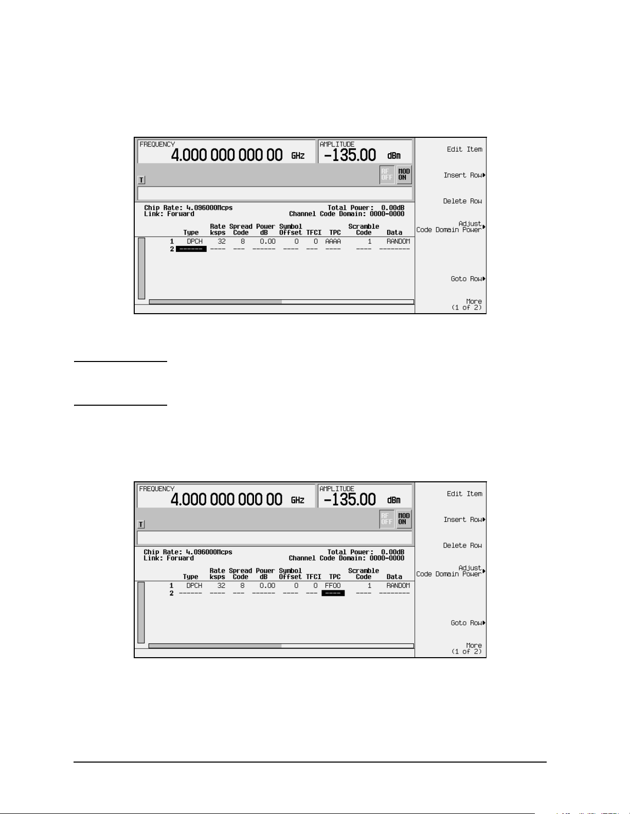
In the following example, you will edit the
TPC, TFCI Power, TPC Power, and Pilot Power
fields of the default predefined channel selection for forward link, which is one dedicated
physical channel (1 DPCH).
1. Press
2. Press
3. Press
4. Press
Preset.
Mode > Arb Waveform Generator (if it appears).
CDMA Formats.
W-CDMA (Rev 1.0-1.2) to display the W-CDMA menu. The default predefined channel
selection for forward link is 1 DPCH.
W-CDMA (Rev. 1.0-1.2) Personality User’s and Programming Guide 2-11
Page 26
Using Functions ESG Family Signal Generators
Selecting Predefined Channel Configurations Option 100
5. Press W-CDMA Define > Edit Channel Setup to display the channel table editor, as shown in
the following figure. Use the front panel knob or arrow keys to move the cursor to table
row 1.
6. Use the right arrow key to highlight the
NOTE TPC values are entered as hexadecimal digits (0-9, A-F). For
TPC value. AAAA should be highlighted.
information on what these values represent, refer to “Understanding
TPC Values” on page 4-5.
7. Press
8. Press
row in the
Edit Item and enter FF00 using the letter softkeys and numeric keypad.
Enter. The TPC value has now been modified and the cursor has moved to the next
TPC column, as shown in the following figure.
9. Use the right arrow key to move the cursor to the
Pilot Power fields, which are currently hidden from view. (The horizontal scroll bar at
the bottom of the screen indicates that there are columns to the right of the
TFCI Power, TPC Power, and
Data
column.)
2-12
W-CDMA (Rev. 1.0-1.2) Personality User’s and Programming Guide
Page 27

ESG Family Signal Generators Using Functions
Option 100 Selecting Predefined Channel Configurations
10.Use the arrow keys to highlight 0.00 dB in the TFCI Power field and press Edit Item > 2 >
dB. The TFCI power has now been offset by 2 dB and the cursor has moved to the next
row in the
TFCI Power column.
11.Use the arrow keys to highlight
dB. The TPC power has now been offset by 3 dB and the cursor has moved to the next
row in the
TPC Power column.
12.Use the arrow keys to highlight
1 > dB. The pilot power has now been offset by 1 dB and the cursor has moved to the next
row in the
Pilot Power column, as shown in the following figure.
0.00 dB in the TPC Power field and press Edit Item > 3 >
0.00 dB in the Pilot Power field and press Edit Item >
NOTE For conceptual information on TFCI, TPC, and pilot power offsets, refer
to “Understanding TFCI, TPC, and Pilot Power Offsets” on page 4-6.
13.Press
FWD WCDMA Setup: 1 DPCH (Modified) as the current configuration.
Return until the status screen appears. The text area displays
To store a custom W-CDMA state, see “Storing a Custom W-CDMA State to Memory” on
page 2-19.
W-CDMA (Rev. 1.0-1.2) Personality User’s and Programming Guide 2-13
Page 28

Using Functions ESG Family Signal Generators
Modifying Reverse Link Channel Configurations Option 100
Modifying Reverse Link Channel Configurations
You can modify reverse link channel configurations using the channel setup table editor.
The following examples show you how to modify predefined channel setups for reverse link
waveform configurations. Refer to “Table Editor Basics” on page 2-2 for additional
information about table editors.
CAUTION Unless previously saved to the signal generator’s memory catalog,
modifications made to predefined channel configurations are lost when
changes are made to link direction.
To store a custom W-CDMA state, see “Storing a Custom W-CDMA
State to Memory” on page 2-19.
Inserting Additional Channels
The default reverse link channel setup after a normal instrument preset is one dedicated
physical control channel (DPCCH). The DPCCH channel always occupies row 1 in the table
editor and is modulated as a Q component. Any additional channels inserted into the table
editor are dedicated physical data channels (DPDCH). The first DPDCH channel occupies
row 2 and is modulated with an I component. The remaining channels (row 3 and greater)
can be modulated with either I or Q, but no two consecutive channels are allowed to have
the same component. The maximum number of reverse link channels is 16.
The following example explains how to insert DPDCH channels into the reverse link
configuration.
Inserting Additional DPDCH Channels
In this example, 15 additional DPDCH channels are inserted into the default predefined
reverse link configuration.
1. Press
2. Press
3. Press
4. Press
Preset.
Mode > Arb Waveform Generator (if it appears).
CDMA Formats.
W-CDMA (Rev 1.0-1.2) to display the W-CDMA menu.
2-14
W-CDMA (Rev. 1.0-1.2) Personality User’s and Programming Guide
Page 29

ESG Family Signal Generators Using Functions
Option 100 Modifying Reverse Link Channel Configurations
5. Press Link Forward Rever se until Reverse highlights. The display reflects the change to
reverse link mode. The text area displays
RVS WCDMA Setup: DPCCH as the current
configuration, as shown in the following figure.
6. Press
W-CDMA Define > Edit Channel Setup to display the channel table editor. Use the arrow
keys to move the cursor to table row 2, as shown.
7. Press
Insert DPDCH > DPDCH Channels. To enter the value, rotate the front panel knob, use
the up and down arrow keys until the number 15 is displayed, or enter 15 using the
numeric keypad. Terminate the entry with the
Enter softkey.
W-CDMA (Rev. 1.0-1.2) Personality User’s and Programming Guide 2-15
Page 30

Using Functions ESG Family Signal Generators
Modifying Reverse Link Channel Configurations Option 100
8. Press Done. The channel table editor now contains the 15 additional channels, as shown
in the following figure. Notice that the first page only displays channels one through
eight. To see the additional channels, press
Goto Row > Page Down.
9. Press
Second DPDCH I Q until I highlights, as shown in the following figure. Notice that
the I/Q setting for the second DPDCH channel (row 3) has changed from Q to I.
Additionally, all subsequent channels have also switched I/Q settings.
10.Press
RVS WCDMA Setup: DPCCH (Modified) as the current configuration.
Return until the status screen appears. The text area displays
To store a custom W-CDMA state, see “Storing a Custom W-CDMA State to Memory” on
page 2-19.
2-16
W-CDMA (Rev. 1.0-1.2) Personality User’s and Programming Guide
Page 31

ESG Family Signal Generators Using Functions
Option 100 Modifying Reverse Link Channel Configurations
Editing Reverse Link Channel Values in the Table Editor
You can use the channel setup table editor to modify reverse link configuration values in
the following columns:
Rate ksps - symbol rate in kilosymbols-per-second
•
Spread Code
•
• Power dB - channel power in decibels
TFCI - transport format combination indicator
•
TPC - transmit power control in hexadecimal
•
•
Data - specific or random data
Highlight the value you wish to change using the front panel arrows or knob, then enter
the new value using the numeric keypad.
In the following example, you will edit the
TPC field of the default predefined channel
selection for reverse link, which is one dedicated physical control channel (1 DPCCH).
1. Press
2. Press
3. Press
4. Press
5. Press
reverse link mode. The text area displays
Preset.
Mode > Arb Waveform Generator (if it appears).
CDMA Formats.
W-CDMA (Rev 1.0-1.2) to display the W-CDMA menu.
Link Forward Reverse until Reverse highlights. The display reflects the change to
RVS WCDMA Setup: DPCCH as the current
configuration, as shown in the following figure.
W-CDMA (Rev. 1.0-1.2) Personality User’s and Programming Guide 2-17
Page 32

Using Functions ESG Family Signal Generators
Modifying Reverse Link Channel Configurations Option 100
6. Press W-CDMA Define > Edit Channel Setup to display the channel table editor, as shown in
the following figure.
7. Use the right arrow key to highlight the
NOTE TPC values are entered as hexadecimal digits (0-9, A-F). For
TPC value. AAAA should be highlighted.
information on what these values represent, refer to “Understanding
TPC Values” on page 4-5.
8. Press
Edit Item and enter FF00 using the letter softkeys and numeric keypad. Press Enter.
The TPC value has now been modified and the cursor has moved to the next row in the
TPC column, as shown in the following figure.
9. Press
RVS WCDMA Setup: DPCCH (Modified) as the current configuration.
Return until the status screen appears. The text area displays
To store a custom W-CDMA state, see “Storing a Custom W-CDMA State to Memory” on
page 2-19.
2-18
W-CDMA (Rev. 1.0-1.2) Personality User’s and Programming Guide
Page 33

ESG Family Signal Generators Using Functions
Option 100 Storing a Custom W-CDMA State to Memory
Storing a Custom W-CDMA State to Memory
In this procedure, you will store the custom W-CDMA state created in the previous
procedure. If you have not performed the previous procedure, turn to “Editing Reverse
Link Channel Values in the Table Editor” on page 2-17 and complete this procedure before
continuing.
Use the following procedure to store and name the custom W-CDMA state to the signal
generator’s memory catalog.
1. To store the custom W-CDMA state, press
Store Custom W-CDMA State. This opens a menu
that accesses the signal generator’s reverse W-CDMA (RWCDMA) memory catalog, as
shown in the following figure.
NOTE The forward link W-CDMA memory catalog is named FWCDMA.
2. To name the custom W-CDMA state, press
Store to File. This opens a menu that allows
you to name the custom W-CDMA state, as shown in the following figure.
W-CDMA (Rev. 1.0-1.2) Personality User’s and Programming Guide 2-19
Page 34

Using Functions ESG Family Signal Generators
Storing a Custom W-CDMA State to Memory Option 100
3. If there is already a file highlighted in the catalog, press Editing K eys > Clear Text, then use
the alphabetic menu and the numeric keypad to enter the file name
Enter. Your custom W-CDMA state CUSTOMREV1 is now saved to the reverse W-CDMA
CUSTOMREV1. Press
memory catalog, as shown.
2-20
W-CDMA (Rev. 1.0-1.2) Personality User’s and Programming Guide
Page 35

ESG Family Signal Generators Using Functions
Option 100 Creating, Storing, & Recalling a Custom Multicarrier W-CDMA Waveform
Creating, Storing, & Recalling a
Custom Multicarrier W-CDMA Waveform
The signal generator provides a quick and easy way to create custom multicarrier
W-CDMA waveforms: rather than building an entire 4-carrier setup from scratch, you can
start with a 4-carrier W-CDMA template and modify the template’s default values as
desired.
Use the following procedure to create, store, and recall a custom, 4-carrier W-CDMA
waveform.
Opening the Multicarrier W-C DM A Set up Table Editor
1. Press Preset.
2. Press
Multicarrier Off On (until On highlights).
3. Press
4. Press
Mode > Arb Waveform Generator (if it appears) > CDMA Formats > W-CDMA (1.0-1.2) >
W-CDMA Select > 4 Carriers to select the template and return to the previous menu.
Multicarrier Define to open the Multicarrier W-CDMA Setup table editor. The
4-carrier W-CDMA template is automatically placed in the table editor, as shown in the
following figure.
Active Entry Area
Multicarrier W-CDMA
Setup softkeys
Carrier Type
W-CDMA (Rev. 1.0-1.2) Personality User’s and Programming Guide 2-21
Frequency Offset Value
Power Value
Page 36

Using Functions ESG Family Signal Generators
Creating, Storing, & Recalling a Custom Multicarrier W-CDMA Waveform Option 100
Modifying a Multicarrier W-CDMA 4-Carrier Template
Use the following steps to modify the standard 4-carrier W-CDMA template that was
loaded in the previous procedure.
Edit the second carrier.
1. Highlight the second channel carrier (in table row 2), then press Edit Item.
2. In the menu that appears, press
3DPCH. This changes the carrier type.
3. Highlight the second carrier’s frequency offset value and press
4. Change the offset value to –625 and press
5. Highlight the second carrier’s power value and press
6. Change the power value to –10 and press
kHz.
Edit Item.
dB.
The following figure shows the edited template:
Edit Item.
2-22
W-CDMA (Rev. 1.0-1.2) Personality User’s and Programming Guide
Page 37

ESG Family Signal Generators Using Functions
Option 100 Creating, Storing, & Recalling a Custom Multicarrier W-CDMA Waveform
Activating a Custom Multicarrier W-CDMA Setup
Using the custom 4-carrier W-CDMA setup from the previous procedure, perform the
following steps to activate the custom multicarrier W-CDMA signal.
1. Press
Setup: 4 Carriers (Modified)
2. Press
Return, and note that the multicarrier setup is now displayed as Multicarrier
.
W-CDMA Off On until On highlights. After waveform generation, the new
multicarrier W-CDMA waveform is stored in volatile memory.
3. Press
RF On/Off. The RF ON annunciator replaces the RF OFF annunciator on the signal
generator’s display, as shown, and the modulated signal is present at the RF output.
W-CDMA (Rev. 1.0-1.2) Personality User’s and Programming Guide 2-23
Page 38

Using Functions ESG Family Signal Generators
Creating, Storing, & Recalling a Custom Multicarrier W-CDMA Waveform Option 100
Storing a Custom Multicarrier W-CDMA Waveform
Use the following procedure to store a custom multicarrier W-CDMA waveform
to the signal generator’s memory. This example uses the custom 4-carrier W-CDMA
waveform created in the previous procedure. If you have not created this custom
multicarrier W-CDMA waveform, refer to “Creating, Storing, & Recalling a
Custom Multicarrier W-CDMA Waveform” on page 2-21.
1. In the top-level W-CDMA menu (
2. Press
Store Custom Multicarrier to display the signal generator’s catalog of multicarrier
W-CDMA Off On is the top key), press Multicarrier Define.
forward W-CDMA (MFWCDMA) files.
3. Press
Store T o File to open a file naming softkey menu of letters and symbols that you can
use to name the file.
4. As described in “Storing a Custom W-CDMA State to Memory” on page 2-19, name and
store this file as
4CARRIER.
Recalling a Custom Multicarrier W-CDMA Waveform
Use the following procedure to recall the custom multicarrier W-CDMA state from the
MFWCDMA memory catalog. This example recalls the custom 4-carrier W-CDMA
waveform stored in the previous procedure.
1. Press
2. Press
Multicarrier Off On (until On highlights).
3. Press
catalog.
4. Highlight the file
waveform
Preset.
Mode > Arb Waveform Generator (if it appears) > CDMA Formats > W-CDMA (Rev 1.0-1.2) >
W-CDMA Select > Custom W-CDMA Multicarrier to open the MFWCDMA memory
4CARRIER, then press Select File. The custom multicarrier W-CDMA
4CARRIER is selected
You can now use the waveform. For details, refer to “Activating a Custom Multicarrier
W-CDMA Setup” on page 2-23.
2-24
W-CDMA (Rev. 1.0-1.2) Personality User’s and Programming Guide
Page 39

ESG Family Signal Generators Using Functions
Option 100 Identifying and Resolving Code Domain Conflicts
Identifying and Resolving Code Domain Conflicts
The code domain space of each channel is defined by the symbol rate and spread code. Code
domain conflicts can arise when two channels of different rates map to the same code
domain space. If code domain conflicts are present when the waveform is turned on, the
conflicting channels are still generated.
NOTE Although the examples in this section use the forward link channel
configuration, the information also applies to reverse link.
Identifying Conflicts
The following figure shows two code domain conflicts. In this example, row 2 occupies the
channel code domain of 0024-0031. Row 5 conflicts with row 2 by occupying the channel
code domain of 0024-0027. Row 6 also conflicts with row 2 by occupying the channel code
domain of 0028-0031. The conflicting channels (rows 5 and 6) are flagged (highlighted) and
each flag includes the row number of the channel it conflicts with, as shown.
W-CDMA (Rev. 1.0-1.2) Personality User’s and Programming Guide 2-25
Page 40

Using Functions ESG Family Signal Generators
Identifying and Resolving Code Domain Conflicts Option 100
Resolving Conflicts
To resolve conflicts, you can change the value of the spread code. To make changes, use the
table editor functions to highlight the value you want to change, then enter the new value
using the front panel keys. In the following figure, the spread code for the channel in row 2
has been changed to 9 to resolve the conflicts in rows 5 and 6.
2-26
W-CDMA (Rev. 1.0-1.2) Personality User’s and Programming Guide
Page 41

ESG Family Signal Generators Using Functions
Option 100 Outputting a W-CDMA Waveform
Outputting a W-CDMA Waveform
This section explains how to set the carrier frequency and power, generate a W-CDMA
waveform, enable the modulation and the RF output, and set the waveform’s clipping
parameters.
Setting the Carrier Frequency and Power
Use the following procedure to set the carrier signal’s power and frequency.
1. Press
2. Press
3. Press
4. Press
Preset.
Mode > Arb Waveform Generator (if it appears).
CDMA Formats.
W-CDMA (Rev 1.0-1.2) to display the W-CDMA menu.
5. For this example, set the RF output frequency to 2.17 GHz by pressing the front panel
Frequency key. Enter 2.17 GHz by rotating the front panel knob, using the up and down
arrow keys, or entering the value using the numeric keypad. (If using the numeric
keypad to enter a new value, terminate the entry with the
6. Set the output power to
−10 dBm by pressing the front panel Amplitude key. Enter −10 by
GHz softkey.)
rotating the front panel knob, using the up and down arrow keys, or entering the value
using the numeric keypad. (If using the numeric keypad to enter a new value, terminate
the entry with the
dBm softkey.)
The carrier frequency and power are now set. The following figure shows the display
with the current configuration.
W-CDMA (Rev. 1.0-1.2) Personality User’s and Programming Guide 2-27
Page 42

Using Functions ESG Family Signal Generators
Outputting a W-CDMA Waveform Option 100
Generating the W-CDMA Waveform and Enabling the
RF Output
Use the following procedure to generate a W-CDMA waveform and activate the RF output.
1. Press
generator displays a message while the waveform is being generated.) The
I/Q annunciators turn on.
2. Toggle the front panel
W-CDMA Off On until On highlights to generate the W-CDMA waveform. (The signal
WCDMA and
RF On/Off key until the display annunciator reads RF ON.
3. Modulation is turned on as a default condition. (The display annunciator shows
.) If modulation is off, toggle the front panel Mod On/Off key.
ON
The W-CDMA signal is now present at the front panel RF OUTPUT connector. The
following figure shows the display with the current configuration.
MOD
Clipping the W-CDMA Waveform
Use the following procedure to configure and apply clipping to the W-CDMA waveform.
1. Notice that in the status area of the display the current clipping setup is
PRE Clip |I+jQ|: 100.0%. A clipping level of 100 percent is equal to no clipping.
2. Press
3. The
the combined I and Q waveform. Alternatively,
and Q waveforms separately.
Use the default selection for this example.
4. Press
5. The
clipped prior to FIR filtering. Alternatively, when you select
clipped after FIR filtering. Use the default selection for this example.
2-28
W-CDMA Define > More (1 of 2) > Clipping to access the clipping setup menu.
Clipping T ype |I+jQ| |I|,|Q| softkey default is |I+jQ| (circular clipping). This selection clips
|I|,|Q| (rectangular clipping) clips the I
Clip |I+jQ| To and enter 80 percent.
Clip At PRE POST FIR Filter softkey default is PRE. With PRE selected, the waveform is
POST, the waveform is
W-CDMA (Rev. 1.0-1.2) Personality User’s and Programming Guide
Page 43

ESG Family Signal Generators Using Functions
Option 100 Outputting a W-CDMA Waveform
6. Press Apply to Waveform. The signal generator rebuilds the waveform and the clipping
settings are updated in the status area of the display, as shown. For more information
on clipping, refer to “Understanding Baseband Clipping” on page 4-8.
W-CDMA (Rev. 1.0-1.2) Personality User’s and Programming Guide 2-29
Page 44

Using Functions ESG Family Signal Generators
Creating a User-Defined FIR Filter Using the FIR Table Editor Option 100
Creating a User-Defined FIR Filter Using the FIR Table Editor
Using this procedure you will create and store an 8-symbol, windowed sinc function filter
with an oversample ratio of 4.
Accessing the Table Editor
Use the following procedure to access the FIR filter table editor.
1. Press
2. Press
3. Press
4. Press
displayed. The following figure shows the FIR table editor.
Preset.
Mode > Arb Waveform Generator (if it appears).
CDMA Formats.
W-CDMA (Rev 1.0-1.2) > W-CDMA Define > Filter > Define User FIR. The FIR table editor is
2-30
W-CDMA (Rev. 1.0-1.2) Personality User’s and Programming Guide
Page 45

ESG Family Signal Generators Using Functions
Option 100 Creating a User-Defined FIR Filter Using the FIR Table Editor
Entering the Coefficient Values
The FIR table editor creates a filter from values that you provide.
1. Use the cursor to highlight the
type the first value (
−0.000076) from the following table. As you press the numeric keys,
Value field for coefficient 0. Use the numeric keypad to
the numbers are displayed in the active entry area. (If you make a mistake, you can
correct it using the backspace key.)
Press
Coefficien
t
0 −0.000076 8 −0.035667
1 −0.001747 9 −0.116753
2 −0.005144 10 −0.157348
3 −0.004424 11 −0.088484
4 0.007745 12 0.123414
5 0.029610 13 0.442748
6 0.043940 14 0.767329
7 0.025852 15 0.972149
Enter. The value for coefficient 0 is now displayed in the Value field, and the cursor
Value
has moved to the second row in the
Value column. The following figure shows the FIR
Coefficien
t
Value
table editor at this point in the process.
2. Continue entering the coefficient values from the table in step 1 until all 16 values are
complete.
W-CDMA (Rev. 1.0-1.2) Personality User’s and Programming Guide 2-31
Page 46

Using Functions ESG Family Signal Generators
Creating a User-Defined FIR Filter Using the FIR Table Editor Option 100
Duplicating the First 16 Coefficients Using Mirror Table
Use the following procedure to duplicate the first 16 coefficients in the FIR filter table
editor.
In a windowed sinc function filter, the second half of the coefficients are identical to the
first half in reverse order. The signal generator provides a mirror table function that
automatically duplicates the existing coefficient values in the reverse order.
Press
Mirror Table. The last 16 coefficients (16 through 31) are automatically generated and
the first of these coefficients (number 16) highlights. The following figure shows the
display at this point in the process.
Setting the Oversample Ratio
The oversample ratio (OSR) is the number of filter taps per symbol. Acceptable values
range from 1 through 32; the maximum combination of symbols and oversampling ratio
allowed by the table editor is 1024. The instrument hardware, however, is actually limited
to 32 symbols, an oversample ratio between 4 and 16, and 256 coefficients. So if you enter
more than 32 symbols or 256 coefficients, the instrument is unable to use the filter. If the
oversample ratio is different from the internal, optimally selected one, then the filter is
automatically resampled to an optimal oversample ratio.
The current OSR value is shown underneath the
Oversample Ratio softkey, as shown in the
previous figure. For this example, set the OSR to 4 (if it isn’t already). Press
Oversample Ratio and use the numeric keypad to enter 4. Press the Enter softkey to terminate
the entry.
2-32
W-CDMA (Rev. 1.0-1.2) Personality User’s and Programming Guide
Page 47

ESG Family Signal Generators Using Functions
Option 100 Creating a User-Defined FIR Filter Using the FIR Table Editor
Displaying a Graphical Representation of the Filter
Use the following procedure to display graphical representations of the active FIR filter.
The signal generator has the capability of graphically displaying the filter in both time and
frequency dimensions.
1. Press
More (1 of 2) > Display FFT to view the filter frequency response (calculated using a
fast Fourier transform). The following graph is displayed.
2. Press
3. Press
Return to return to the menu keys.
Display Impulse Response to display the filter impulse response in time. The
following graph is displayed.
4. Press
W-CDMA (Rev. 1.0-1.2) Personality User’s and Programming Guide 2-33
Return to return to the menu keys.
Page 48

Using Functions ESG Family Signal Generators
Creating a User-Defined FIR Filter Using the FIR Table Editor Option 100
Storing the Filter to Memory
The filter is now complete and can be stored to non-volatile memory for future use. At any
time you can check the information at the top of the FIR table editor to determine whether
the current table has been stored. Your current table should display the following text:
FIR Values (UNSTORED). If you attempt to exit the table editor mode without first storing
to a file, the signal generator first prompts you to confirm that you want to exit without
storing to a file. If you do not want to exit after all, press
To store the file, perform the following steps.
Return.
1. Press
Load/Store > Store To File. The catalog of FIR files appears along with the amount of
memory available.
2. For this example, you will title the file NEWFIR1. The file name is created by pressing
the softkey containing the desired character, then selecting the softkey with that
character from the subsequent menu. For example, press the
press the bottom softkey,
text.
to:
N. N is displayed in the active entry area following the Store
3. Continue entering the characters for the file name until
HIJKLMN softkey. Then
NEWFIR1 is displayed in the
active entry area. (Use the numeric keypad to enter the number 1.)
4. Press
Enter when the file name is complete. The contents of the current FIR table editor
are stored to a file in non-volatile memory. The following figure shows the display.
The NEWFIR1 file is the first file name listed. (If you have previously stored other FIR
files, additional file names are listed below NEWFIR1.) The file type is FIR and the size
of the file is 260 bytes. The amount of memory used is also displayed. The number of
files that can be saved depends on the size of the files and the amount of memory used.
Memory is also shared by instrument state files and list sweep files.
This filter can now be used to customize a modulation or it can be used as a basis for a
new filter design. (Refer to the additional filter examples in this chapter.)
2-34
W-CDMA (Rev. 1.0-1.2) Personality User’s and Programming Guide
Page 49

ESG Family Signal Generators Using Functions
Option 100 Modifying an FIR Filter Using the FIR Table Editor
Modifying an FIR Filter Using the FIR Table Editor
FIR filters stored in the signal generator memory can easily be modified using the FIR
table editor. You can load the FIR table editor with coefficient values from user-defined FIR
files stored in the signal generator’s memory, or from one of the default FIR filters. Then
you can modify the values, and store the new files. In this example, you will load the FIR
table editor with the values for a default Gaussian filter and then modify it.
Loading the Default Gaussian FIR File
Use the following procedure to load the default Gaussian FIR filter into the FIR filter table
editor.
1. Press
2. Press
3. Press
4. Press
5. Set the filter BbT to 0.300 (if
Filter BbT and rotate the front panel knob until 0.300 is displayed.
6. Set the number of filter symbols to 8 (if
pressing
7. Press
Preset.
Mode > Arb Waveform Generator (if it appears).
CDMA Formats > W-CDMA (Rev 1.0-1.2) > W-CDMA Define.
Filter > Define User FIR > More (1 of 2) > Load Default FIR > Gaussian.
Filter BbT is not already set to this value) by pressing
Filter Symbols is not already set to this value) by
Filter Symbols and rotating the front panel knob until 8 is displayed.
Generate. The FIR table editor should now contain the coefficient values for the
specified Gaussian filter.
NOTE The actual oversample ratio during modulation is automatically
selected by the instrument. A value between 4 and 16 is chosen
dependent on the symbol rate, the number of bits per symbol of the
modulation type, and the number of symbols.
W-CDMA (Rev. 1.0-1.2) Personality User’s and Programming Guide 2-35
Page 50

Using Functions ESG Family Signal Generators
Modifying an FIR Filter Using the FIR Table Editor Option 100
8. Press Display Impulse Response for a graphic representation of the filter impulse response
as shown in the following figure.
9. Press
Return to return to the menu keys.
Modifying the Coefficients
Use the following procedure to modify the filter coefficients in the FIR filter table editor.
1. Highlight coefficient 15.
2. Press
0 > Enter to change the value of the coefficient to 0.
3. Press
Display Impulse Response to see the effects of the change.
The graphic display can provide a useful troubleshooting tool (in this case, it indicates
that a coefficient value is missing, resulting in an improper Gaussian response).
2-36
W-CDMA (Rev. 1.0-1.2) Personality User’s and Programming Guide
Page 51

ESG Family Signal Generators Using Functions
Option 100 Modifying an FIR Filter Using the FIR Table Editor
4. Press Return to return to the menu keys.
5. In addition to changing existing values, you can also insert and delete rows of
coefficients and change the oversample ratio. (Press
More (2 of 2) to access these softkeys.)
6. Highlight coefficient 15.
7. Press 1 > Enter. This changes coefficient 15 back to its original value.
Storing the Filter to Memory
Perform the following procedure to store the modified Gaussian filter to the signal
generator’s memory catalog.
1. Press
Load/Store > Store To File. The catalog of FIR files is displayed along with the
amount of memory available.
2. Name the file NEWFIR2.
3. Press
Enter when the file name is complete. The contents of the current FIR table editor
are stored to a file in non-volatile memory, and the catalog of FIR files is updated to
show the new file.
W-CDMA (Rev. 1.0-1.2) Personality User’s and Programming Guide 2-37
Page 52

Using Functions ESG Family Signal Generators
Applying a User-Defined FIR Filter to a W-CDMA Waveform Option 100
Applying a User-Defined FIR Filter to a W-CDMA Waveform
Custom FIR filters can be created using the FIR table editor feature or they can be created
externally and downloaded into the signal generator memory. Once the filter is stored in
memory, it can be selected for use with your custom modulation state. This example
requires that at least one FIR file be already stored in memory. For an example of creating
and storing a FIR filter, see “Creating a User-Defined FIR Filter Using the FIR Table
Editor” on page 2-30.
1. Press
2. Press
3. Press
4. Press
Preset.
Mode > Arb Waveform Generator (if it appears).
CDMA Formats.
W-CDMA (Rev 1.0-1.2) > W-CDMA Define > Filter > Select > User FIR. The catalog of FIR
files should now be displayed. The following figure shows an example of the catalog.
In this example, there are two FIR files listed: NEWFIR1 and NEWFIR2. (These files
were created in the previous examples.)
5. Scroll down in the list until the desired filter highlights. In this example, NEWFIR2 is
the desired filter. You can use the front panel knob or the arrow keys as well as the
GoTo Row function to highlight the filter.
2-38
W-CDMA (Rev. 1.0-1.2) Personality User’s and Programming Guide
Page 53

ESG Family Signal Generators Using Functions
Option 100 Applying a User-Defined FIR Filter to a W-CDMA Waveform
6. Press Select File . The highlighted filter is now selected for use in your custom modulation
state, as shown.
The filter you selected is NEWFIR2. You can see the name, followed by
below the
Select softkey. In the Filter field, near the left of the display, User FIR is
@FIR, displayed
displayed to indicate that a user-defined FIR filter has been selected.
Once you have set the other modulation parameters to your satisfaction, turn on
Custom and the RF output and your user-defined filter is in use.
NOTE The actual oversample ratio during modulation is automatically
selected by the instrument. A value between 4 and 16 is chosen
dependent on the symbol rate, the number of bits per symbol of the
modulation type, and the number of symbols.
W-CDMA (Rev. 1.0-1.2) Personality User’s and Programming Guide 2-39
Page 54

Using Functions ESG Family Signal Generators
Applying a User-Defined FIR Filter to a W-CDMA Waveform Option 100
2-40
W-CDMA (Rev. 1.0-1.2) Personality User’s and Programming Guide
Page 55

ESG Family Signal Generators
Option 100
3 Softkey Reference
This chapter describes the Mode hardkey and the associated softkeys used to configure and
activate functions specific to the Option 100, W-CDMA (Revision 1.0-1.2) personality.
The softkeys are presented in alphanumeric order.
W-CDMA (Rev. 1.0-1.2) Personality User’s and Programming Guide 3-1
Page 56

Softkey Reference ESG Family Signal Generators
Mode Key Option 100
Mode Key
n ksps
When you press the front-panel Mode key, the softkeys that appear
depend on how many options are included in the instrument. When an
instrument has options in addition to the UND option, the softkey
Arb Waveform Generator provides access to all Dual Arbitrary Waveform
Generator softkeys (including the optional personalities).
The softkeys described in this chapter are available only under the
W-CDMA (Rev 1.0−1.2) softkey.
For information on the SCPI commands that duplicate these softkeys
remotely, see Chapter 5, “Remote Programming,” and Chapter 6,
“Programming Command Cross-Reference.”
This key sets the symbol rate. It is used for an inserted DPCH or
Spread Only forward link channel, for multiple channels in the
W-CDMA Edit Channel Setup table editor, and for multiple reverse link
dedicated physical data channels (DPDCH).
The values available are the following:
8 ksps 128 ksps
3-2
16 ksps 256 ksps
32 ksps 512 ksps
64 ksps 1024 ksps
W-CDMA (Rev. 1.0-1.2) Personality User’s and Programming Guide
Page 57

ESG Family Signal Generators Softkey Reference
Option 100 Mode Key
Softkey Location (Forward Link): Mode > CDMA Formats >
W-CDMA (Rev 1.0−1.2) > W-CDMA Define > Edit Channel Setup > Insert Row >
DPCH (or Spread Only > or Multiple Channels > Symbol Rate)> n ksps
(See above description of (n) ksps.)
1 DPCH
2 Carriers
Softkey Location (Reverse Link):
1.0−1.2)
n ksps (See above description of (n) ksps.)
> W-CDMA Define > Edit Channel Setup > Insert DPDCH > Symbol Rate >
Mode > CDMA Formats > W-CDMA (Rev
Selects a single DPCH forward link channel for either the W-CDMA
setup or the carrier in the multicarrier table editor.
Softkey Location:
W-CDMA Select > 1DPCH
Mode > CDMA Formats > W-CDMA (Rev 1.0−1.2) >
Or: Mode > CDMA Formats > W-CDMA (Re v 1 .0−1.2) > Multicarrier Off On >
Multicarrier Define > Edit Item > 1DPCH
Or: Mode > CDMA Formats > W-CDMA (Re v 1 .0−1.2) > Multicarrier Off On >
Multicarrier Define > Insert Row > 1DPCH
Selects a standard 2-carrier W-CDMA setup with the settings listed
below. (See also “W-CDMA Select” on page 3-35.)
Carrier 1: Perch channel,
−7.5 MHz frequency offset, 0 dB power
2.500 MHz
Carrier 2: Perch channel, 7.5 MHz frequency offset, 0 dB power
Softkey Location:
Multicarrier Off On > W-CDMA Select > 2 Carriers
Mode > CDMA Formats > W-CDMA (Rev 1.0−1.2) >
Selects a reconstruction filter with a cutoff frequency of 2.500 MHz.
Softkey Location:
CDMA Define > Reconstruction Filter > 2.500 MHz
Mode > CDMA Formats > W-CDMA (Rev 1.0−1.2) >
W-CDMA (Rev. 1.0-1.2) Personality User’s and Programming Guide 3-3
Page 58

Softkey Reference ESG Family Signal Generators
Mode Key Option 100
3 Carriers
Selects a standard 3-carrier W-CDMA setup with the settings listed
below. (See also “W-CDMA Select” on page 3-35.)
3 DPCH
4 Carriers
Carrier 1: Perch channel,
−5 MHz frequency offset, 0 dB power
Carrier 2: Perch channel, 0 kHz frequency offset, 0 dB power
Carrier 3: Perch channel, 5 MHz frequency offset, 0 dB power
Softkey Location:
Multicarrier Off On > W-CDMA Select > 3 Carriers
Mode > CDMA Formats > W-CDMA (Rev 1.0−1.2) >
Selects three DPCH forward link channels for either the W-CDMA
setup or the carrier in the multicarrier table editor.
Softkey Location:
W-CDMA Select > 3DPCH
Mode > CDMA Formats > W-CDMA (Rev 1.0−1.2) >
Or: Mode > CDMA Formats > W-CDMA (Re v 1 .0−1.2) > Multicarrier Define >
Edit Item > 3DPCH
Or: Mode > CDMA Formats > W-CDMA (Re v 1 .0−1.2) > Multicarrier Define >
Insert Row > 3DPCH
8.000 MHz
Selects a standard 4-carrier W-CDMA setup with the settings listed
below. (See also “W-CDMA Select” on page 3-35.)
Carrier 1: Perch channel,
Carrier 2: Perch channel,
−7.5 MHz frequency offset, 0 dB power
−2.5 MHz frequency offset, 0 dB power
Carrier 3: Perch channel, 2.5 MHz frequency offset, 0 dB power
Carrier 4: Perch channel, 7.5 MHz frequency offset, 0 dB power
Softkey Location:
Multicarrier Off On > W-CDMA Select > 4 Carriers
Mode > CDMA Formats > W-CDMA (Rev 1.0−1.2) >
Selects a reconstruction filter with a cutoff frequency of 8.000 MHz.
Softkey Location:
W-CDMA Define > Reconstruction Filter > 8.000 MHz
Mode > CDMA Formats > W-CDMA (Rev 1.0−1.2) >
3-4
W-CDMA (Rev. 1.0-1.2) Personality User’s and Programming Guide
Page 59

ESG Family Signal Generators Softkey Reference
Option 100 Mode Key
250 kHz
Selects a reconstruction filter with a cutoff frequency of 250 kHz.
Softkey Location:
W-CDMA Define > Reconstruction Filter > 250.0 kHz
Mode > CDMA Formats > W-CDMA (Rev 1.0−1.2) >
Adjust Code Domain Power
Accesses a menu that enables you to adjust the code domain power (the
relative power in each of the channels). Select
channels are of equal energy per bit and the total power equals 0 dB), or
Scale to 0 dB (scale all of the current channel powers so that the total
power equals 0 dB while keeping the previous relative power ratios
between the individual channels). Available in Forward Link only.
Softkey Location:
W-CDMA Define > Edit Channel Setup > Adjust Code Domain Power
Mode > CDMA Formats > W-CDMA (Rev 1.0−1.2) >
APCO 25 C4FM
Press this softkey to select an APCO 25-specified C4FM filter in the
Select (filter) menu. This is a Nyquist filter with an alpha of 0.2 which
is combined with a shaping filter. This softkey is only available when
Multicarrier Off On is toggled to Off.
Softkey Location:
W-CDMA Define > Filter > Select > APCO 25 C4FM
Mode > CDMA Formats > W-CDMA (Rev 1.0-1.2) >
Equal Energy per Symbol (all
Apply Channel Setup
Applies the changes made in the channel setup table editor (see “Edit
Channel Setup” on page 3-12) for the current link. If the waveform is
set to
On, the new channel data generates a new modulation waveform
in ARB waveform memory.
Softkey Location:
W-CDMA Define > Apply ChannelSetup
Apply Multicarrier
Applies the current settings in the multicarrier table editor. (See also
“Multicarrier Define” on page 3-22.)
Softkey Location:
Multicarrier Off On > Multicarrier Define > Apply Multicarrier
Mode > CDMA Formats > W-CDMA (Rev 1.0−1.2) >
Mode > CDMA Formats > W-CDMA (Rev 1.0-1.2) >
W-CDMA (Rev. 1.0-1.2) Personality User’s and Programming Guide 3-5
Page 60

Softkey Reference ESG Family Signal Generators
Mode Key Option 100
Apply To Waveform
Use this terminator softkey to apply the current clipping settings you
have selected to the waveform. Press
the new settings at this time.
NOTE The settings are applied the next time you generate a waveform.
Return if you do not want to apply
Softkey Location:
W-CDMA Define > Clipping > Apply To Waveform
ARB Reference Ext Int
Selects either an internal or an external reference for the waveform
clock. If you choose external, you must enter the reference frequency (as
described under the
the signal to the BASEBAND GEN REF IN connector.
Default Value: Int39
Softkey Location:
W-CDMA Define > ARB Reference Ext Int
Bus
Sets the trigger source to bus. When the trigger source is set to bus, the
signal generator triggers an event when it receives the appropriate
command via GPIB.
Softkey Location:
Trigger Setup > Trigger Source > Bus
Mode > CDMA Formats > W-CDMA (Rev 1.0−1.2) >
Reference Frequency softkey on page 3-27) and apply
Mode > CDMA Formats > W-CDMA (Rev 1.0−1.2) >
Mode > CDMA Formats > W-CDMA (Rev 1.0−1.2) > Trigger >
Channels
3-6
Press this softkey, then enter the number of duplicate channels that you
want to set up and insert into the Edit Channel Setup table editor.
Press the softkey
Enter to terminate the entry.
After you have set the channel parameters, and the number of times
you want the channel duplicated, press
Done to insert the information
into the table editor.
Default Value: 1
Range: 1 through 511
Softkey Location:
W-CDMA Define > Edit Channel Setup > Insert Row > Multiple Channels >
Channels
Mode > CDMA Formats > W-CDMA (Rev 1.0−1.2) >
W-CDMA (Rev. 1.0-1.2) Personality User’s and Programming Guide
Page 61

ESG Family Signal Generators Softkey Reference
Option 100 Mode Key
Chip Rate
Displays a menu where you can choose the chip rate for the channels in
the current table editor.
Default Value: 4.096000 Mcps
Available Values (in Mcps): 4.096, 8.192, 16.384
Softkey Location:
W-CDMA Define > Edit Channel Setup > Chip Rate
Clip |I+jQ| To
Use this softkey to make the modulation level of the combined I and Q
waveform the active function. You can then clip (limit) the level to a
percentage of full scale. A level of 100.0% equates to no clipping.
Default Value: 100.0%
Range: 10.0 through 100.0%, in 0.1% increments
Softkey Location:
W-CDMA Define > Clipping > Clip |I+jQ| T o
Clip |I| To
Use this softkey to make the modulation level of the I component the
active function. You can then clip (limit) the level to a percentage of full
scale. A level of 100.0% equates to no clipping.
Default Value: 100.0%
Range: 10.0 through 100.0%, in 0.1% increments
Mode > CDMA Formats > W-CDMA (Rev 1.0−1.2) >
Mode > CDMA Formats > W-CDMA (Rev 1.0−1.2) >
Softkey Location:
W-CDMA Define > Clipping > Clip |I| To
Mode > CDMA Formats > W-CDMA (Rev 1.0−1.2) >
Clip |Q| To
Use this softkey to make the modulation level of the Q component the
active function. You can then clip (limit) the level to a percentage of full
scale. A level of 100.0% equates to no clipping.
Default Value: 100.0%
Range: 10.0 through 100.0% in 0.1% increments
Softkey Location:
W-CDMA Define > Clipping > Clip |Q| T o
W-CDMA (Rev. 1.0-1.2) Personality User’s and Programming Guide 3-7
Mode > CDMA Formats > W-CDMA (Rev 1.0−1.2) >
Page 62

Softkey Reference ESG Family Signal Generators
Mode Key Option 100
Clip At PRE POST FIR Filter
Use this softkey to select whether you want the waveform clipped
before (PRE) or after (POST) FIR filtering.
Default Value: PRE
Softkey Location:
W-CDMA Define > Clipping > Clip At PRE POST FIR Filter
Mode > CDMA Formats > W-CDMA (Rev 1.0−1.2) >
Clipping
Press this softkey to access a menu of options for limiting the
modulation level.
Softkey Location:
W-CDMA Define > Clipping
Mode > CDMA Formats > W-CDMA (Rev 1.0−1.2) >
Clipping Type |I+jQ| |I|,|Q|
Use this softkey to select either |I+jQ| or |I|,|Q| as the clipping type.
If you select |I+jQ|, the combined I and Q waveform is clipped (circular
clipping). If you select |I|,|Q|, the I and Q components of the
waveform are clipped independently (rectangular clipping). In this case,
you can clip I and Q to different levels.
Default Value: |I+jQ|
Softkey Location:
W-CDMA Define > Clipping > Clipping Type |I+jQ| |I|,|Q|
Mode > CDMA Formats > W-CDMA (Rev 1.0−1.2) >
Continuous
Sets the W-CDMA trigger type to continuous. In continuous trigger
mode, the waveform repeats itself indefinitely.
Softkey Location:
Continuous
Custom W-CDMA Carrier
Displays the forward link W-CDMA (FWCDMA) memory catalog. From
this catalog listing, you can choose a previously stored custom carrier
setup.
Softkey Location:
Multicarrier Off On > Multicarrier Define > Edit Item > Custom W-CDMA Carrier
Or: Mode > CDMA Formats > W-CDMA (Rev 1.0-1.2) > Multicarrier Off On >
Multicarrier Define > Insert Row > Custom W-CDMA Carrier
3-8
Mode > CDMA Formats > W-CDMA (Rev 1.0−1.2) > Trigger >
Mode > CDMA Formats > W-CDMA (Rev 1.0-1.2) >
W-CDMA (Rev. 1.0-1.2) Personality User’s and Programming Guide
Page 63

ESG Family Signal Generators Softkey Reference
Option 100 Mode Key
Custom W-CDMA Multicarrier
Displays the multicarrier forward link W-CDMA (MFWCDMA) memory
catalog. From this catalog listing, you can choose a previously stored
custom multicarrier setup.
Softkey Location:
Multicarrier Off On > W-CDMA Select > Custom W-CDMA Multicarrier
Custom W-CDMA State
Displays the W-CDMA Setup Select File menu for the current link,
where you can choose a previously stored custom W-CDMA setup.
Softkey Location:
W-CDMA Select > Custom W-CDMA State
Define User FIR
Accesses a table editor for creating and modifying FIR filters. The FIR
table editor allows a maximum filter length of 1024 taps with a
maximum oversampling ratio of 32. An FIR filter selected for use in
W-CDMA, however, cannot have more than 256 taps so the number of
symbols and the oversample ratio should be selected accordingly.
Examples of using the FIR table editor are provided in the “Using
Functions” chapter.
Softkey Location:
W-CDMA Define > Filter > Define User FIR
Mode > CDMA Formats > W-CDMA (Rev 1.0-1.2) >
Mode > CDMA Formats > W-CDMA (Rev 1.0−1.2) >
Mode > CDMA Formats > W-CDMA (Rev 1.0−1.2) >
Delete All Rows
Deletes all rows in the current table editor.
Deletions cannot be recovered.
Delete All Rows is located in some table editors.
Delete File
Deletes the highlighted file from the displayed catalog. You will be
prompted for confirmation.
Delete File is located in catalogs of files.
Delete Row
Deletes the highlighted row in the table.
Deletions cannot be recovered.
Softkey Location:
W-CDMA Define > Edit Channel Setup > Delete Row
Mode > CDMA Formats > W-CDMA (Rev 1.0−1.2) >
W-CDMA (Rev. 1.0-1.2) Personality User’s and Programming Guide 3-9
Page 64

Softkey Reference ESG Family Signal Generators
Mode Key Option 100
Display FFT
Displays a graphical representation of the frequency response of the
filter loaded into the FIR table editor (calculated using a fast Fourier
transform). The following is an example of the frequency response of a
root Nyquist filter with an oversample ratio of 4.
To return to the FIR table editor and the menu keys, press
Softkey Location:
W-CDMA Define > Filter > Define User FIR > Display FFT
Display Impulse Response
Displays a graphical representation of impulse response in time of the
filter loaded into the FIR table editor. The following is an example of the
impulse response of a root Nyquist filter with an oversample ratio of 4.
To return to the FIR table editor and the menu keys, press
Softkey Location:
W-CDMA Define > Filter > Define User FIR > Display Impulse Response
Return.
Mode > CDMA Formats > W-CDMA (Rev 1.0−1.2) >
Return.
Mode > CDMA Formats > W-CDMA (Rev 1.0−1.2) >
DPCCH
3-10
Selects a single DPCCH channel for the reverse link channel setup.
Softkey Location:
W-CDMA Select > DPCCH
Mode > CDMA Formats > W-CDMA (Rev 1.0−1.2) >
W-CDMA (Rev. 1.0-1.2) Personality User’s and Programming Guide
Page 65

ESG Family Signal Generators Softkey Reference
Option 100 Mode Key
DPCCH + 1 DPDCH
Selects a DPCCH channel plus one DPDCH channel for the reverse link
channel setup.
Softkey Location:
W-CDMA Select
DPCCH + 2 DPDCH
Selects a DPCCH channel plus two DPDCH channels for the reverse
link channel setup.
Softkey Location:
W-CDMA Select > DPDCH + 2 DPDCH
DPCCH + 3 DPDCH
Selects a DPCCH channel plus three DPDCH channels for the reverse
link channel setup.
Softkey Location:
W-CDMA Select > DPDCH + 3 DPDCH
DPCH
Displays a menu where you can choose the symbol rate (in ksps) of the
DPCH channel that is then inserted into the forward link Edit Channel
Setup table editor.
Mode > CDMA Formats > W-CDMA (Rev 1.0−1.2) >
> DPCCH + 1 DPDCH
Mode > CDMA Formats > W-CDMA (Rev 1.0−1.2) >
Mode > CDMA Formats > W-CDMA (Rev 1.0−1.2) >
Softkey Location:
W-CDMA Define > Edit Channel Setup > Insert Row > DPCH
DPDCH Channels
Sets the number of DPDCH channels being inserted into the reverse
link Edit Channel Setup table editor.
Softkey Location:
W-CDMA Define > Edit Channel Setup > Insert DPDCH > DPDCH Channels
Mode > CDMA Formats > W-CDMA (Rev 1.0−1.2) >
Mode > CDMA Formats > W-CDMA (Rev 1.0−1.2) >
W-CDMA (Rev. 1.0-1.2) Personality User’s and Programming Guide 3-11
Page 66

Softkey Reference ESG Family Signal Generators
Mode Key Option 100
Edit Channel Setup
Accesses a table editor where you can define the channel parameters of
the current W-CDMA signal for the current link.
Use the front-panel knob or the arrow keys to move the cursor within
the table structure, and the numeric keypad to change values contained
in the table.
NOTE Using the keys found beneath the Goto Row softkey, you can move more
quickly through a large table.
Softkey Location:
W-CDMA Define > Edit Channel Setup
Edit Item
Changes the highlighted item in the displayed table.
Softkey Location:
W-CDMA Define > Edit Channel Setup > Edit Item
Or: Mode > CDMA Formats > W-CDMA (Rev 1. 0-1.2) > Multicarrier Off On >
Multicarrier Define > Edit Item
Equal Energy per Symbol
Sets the selected channel powers to equal energy per symbol
(referenced to 8 ksps, and increasing by 3 dB for each doubling of the
symbol rate). Available in Forward Link only.
Softkey Location:
W-CDMA Define > Edit Channel Setup > Adjust Code Domain Power >
Equal Energy per Symbol
Ext
Mode > CDMA Formats > W-CDMA (Rev 1.0−1.2) >
Mode > CDMA Formats > W-CDMA (Rev 1.0−1.2) >
Mode > CDMA Formats > W-CDMA (Rev 1.0−1.2) >
3-12
Sets the trigger source to external triggering. When the trigger source
is set to external, the signal generator will trigger an event when it
receives the appropriate signal via the PATTERN TRIG IN connector.
Softkey Location:
Trigger Setup > Trigger Source > Ext
Mode > CDMA Formats > W-CDMA (Rev 1.0−1.2) > Trigger >
W-CDMA (Rev. 1.0-1.2) Personality User’s and Programming Guide
Page 67

ESG Family Signal Generators Softkey Reference
Option 100 Mode Key
Ext Delay
Arms (On) or disarms (Off) the external trigger delay. To use external
trigger delay, press this softkey until
then set the external delay time by pressing the
Default Value: Off
Ext Delay On is highlighted, and
Ext Delay Time softkey.
Softkey Location:
Trigger Setup > Trig ger Source > Ext Delay Off On
Ext Delay Time
Sets the time for the external trigger delay. External trigger delay may
be adjusted to trigger a waveform at a specified length of time after an
external trigger signal has been received at the PATTERN TRIG IN
connector. Enter a new value and press the
To use external trigger delay, press
highlighted, and then set the external delay time by pressing the
Ext Delay Time softkey.
Default Value: 2.000 milliseconds
Range: 2.0 microseconds through 3600 seconds.
Softkey Location:
Trigger Setup > Trigger Source > Ext Delay Time
Ext Polarity Neg Pos
Sets the external trigger source polarity to either a positive change or a
negative change in signal level. Depending on your choice, the signal
generator will trigger an event when it receives the appropriate positive
or negative change in signal at the PATTERN TRIG IN connector.
Mode > CDMA Formats > W-CDMA (Rev 1.0−1.2) > Trigger >
Enter terminator softkey.
Ext Delay Off On until On is
Mode > CDMA Formats > W-CDMA (Rev 1.0−1.2) > Trigger >
Default Value: Neg
Softkey Location:
Trigger Setup > Trigger Source > Ext Polarity Neg Pos
Mode > CDMA Formats > W-CDMA (Rev 1.0−1.2) > Trigger >
Filter
Accesses menus for selecting a filter type, restoring the default filter,
and for defining a unique FIR filter. The Filter menu also lets you
adjust the filter alpha (when Nyquist or root Nyquist filters are
selected) or bandwidth time product (for Gaussian filters).
Softkey Location:
W-CDMA Define > Filter
W-CDMA (Rev. 1.0-1.2) Personality User’s and Programming Guide 3-13
Mode > CDMA Formats > W-CDMA (Rev 1.0−1.2) >
Page 68

Softkey Reference ESG Family Signal Generators
Mode Key Option 100
Filter Alpha
Changes the FIR filter’s alpha parameter in either the Filter menu or
the Load Default FIR menus.
In the Filter Menu
Changes the alpha parameter of the selected root Nyquist or Nyquist
filter. To enter a new value, rotate the front-panel knob until the
desired value is displayed, use the up and down arrow keys, or enter the
value using the numeric keypad and press the
This key only appears after choosing a root Nyquist or Nyquist filter. If
a Gaussian filter is in use, you will see
use, you will see a grayed-out softkey:
Filter BbT. If any other filter is in
Filter Factor N/A.
Default Value: 0.500
Range: 0.000 through 1.000
Enter terminator softkey.
Filter BbT
Softkey Location:
W-CDMA Define > Filter > Filter Alpha
Mode > CDMA Formats > W-CDMA (Rev 1.0−1.2) >
In the Load Default FIR Menu
Changes the alpha parameter of the root Nyquist or Nyquist filter
coefficients loaded into the FIR table editor. After entering the alpha
value, press
Generate to modify the filter coefficients in the table editor.
Default Value: 0.350
Softkey Location:
W-CDMA Define > Filter > Define User FIR > Load Default FIR > Root Nyquist (or
Nyquist)> Filter Alpha
Mode > CDMA Formats > W-CDMA (Rev 1.0−1.2) >
Changes the bandwidth-multiplied-by-bit-time (BbT) filter parameter
in either the Filter menu or the Load Default FIR menu.
In the Filter Menu
In the Filter menu, Filter Bbt changes the BbT parameter of the selected
Gaussian filter.
NOTE This key appears only after choosing a Gaussian filter. If a root Nyquist
or Nyquist filter is in use, you will see
Filter Alpha. If any other filter is in
use, you will see a Filter Factor N/A softkey (grayed-out).
Default Value: 0.500
Range: 0.000 through 1.000
3-14
W-CDMA (Rev. 1.0-1.2) Personality User’s and Programming Guide
Page 69

ESG Family Signal Generators Softkey Reference
Option 100 Mode Key
Softkey Location: Mode > CDMA Formats > W- CD MA (Rev 1.0−1.2) >
W-CDMA Define > Filter > Select > Gaussian > Filter BbT
In the Load Default FIR Menu
Changes the BbT parameter of the Gaussian filter coefficients loaded
into the FIR table editor. After entering the BbT value, press
modify the filter coefficients in the table editor.
Default Value: 0.300
Generate to
Softkey Location:
W-CDMA Define > Filter > Define User FIR > Load Default FIR > Gaussian >
Filter BbT
Filter Factor
This grayed-out softkey is displayed when a filter is in use that doesn’t
contain an adjustable alpha or BbT parameter (such as the IS-95 filter
selections or a user-defined FIR filter). This softkey changes to either
Filter Alpha or Filter BbT if the appropriate root Nyquist, Nyquist, or
Gaussian filter is selected for use.
Softkey Location:
W-CDMA Define > Filter > Filter Factor
Filter Symbols
Defines the number of symbols for the filter to be loaded into the FIR
table editor. The FIR table editor allows a maximum filter length of
1024 coefficients with a maximum oversample ratio of 32 and a
maximum of 32 symbols. An FIR filter selected for use in W-CDMA,
however, cannot have more than 256 coefficients so the number of
symbols and the oversample ratio should be selected accordingly.
Mode > CDMA Formats > W-CDMA (Rev 1.0−1.2) >
Mode > CDMA Formats > W-CDMA (Rev 1.0−1.2) >
To change the number of symbols, rotate the front-panel knob until the
desired value is displayed, use the up and down arrow keys, or enter the
value using the numeric keypad and press the
Enter terminator softkey.
Default Value: 8
Range: 1 through 32
Softkey Location:
W-CDMA Define > Filter > Define User FIR > Load Default FIR > Root Nyquist (or
Nyquist, Gaussian, or Rectangle)> Filter Symbols
W-CDMA (Rev. 1.0-1.2) Personality User’s and Programming Guide 3-15
Mode > CDMA Formats > W-CDMA (Rev 1.0−1.2) >
Page 70

Softkey Reference ESG Family Signal Generators
Mode Key Option 100
First Spread Code
This softkey appears in the Multiple Channels menu, where you define
a channel and then insert multiple entries of that channel into the Edit
Channel Setup table editor.
Press the
First Spread Code softkey, then enter the value that you want
for the starting spread code for the channels that will be inserted. Press
the softkey
NOTE Check existing entries in the table editor to be sure that there will be no
duplication of an existing spread code. If there is, the warning
Conflict
Enter to terminate the entry.
Domain
is displayed in the table. If this happens, select any duplicate
Spread Code entries and give them unique values.
After you have set the channel parameters, and the number of times
you want the channel duplicated, press
Done to insert the information
into the table editor.
Default Value: 8
Range: 0 through 15
Softkey Location:
W-CDMA Define > Edit Channel Setup > Insert Row > Multiple Channels >
First Spread Code
Mode > CDMA Formats > W-CDMA (Rev 1.0−1.2) >
Gate Active
This softkey remains grayed-out until the trigger is set to Gated. Once
the trigger has been set to Gated, press
polarity of the “through” or active state of a gated trigger signal. Gate
Active Low will output the signal while the gate is low at the PATTERN
TRIG IN connector. Gate Active High has the opposite effect, outputting
the signal while the signal level at the PATTERN TRIG IN connector is
in a high state.
Gate Active Low High to toggle the
Gated
3-16
Softkey Location:
Trigger Setup > Gate Active
Mode > CDMA Formats > W-CDMA (Rev 1.0−1.2) > Trigger >
Sets the trigger type to Gated. Using a gated trigger, you can set the
signal to output when a TTL high or low is present at the PATTERN
TRIG IN connector. To set the gate to trigger on either high or low, press
Gated and then press Trigger Setup > Gate Active Low High.
Softkey Location:
Gated
Mode > CDMA Formats > W-CDMA (Rev 1.0−1.2) > Trigger >
W-CDMA (Rev. 1.0-1.2) Personality User’s and Programming Guide
Page 71

ESG Family Signal Generators Softkey Reference
Option 100 Mode Key
Gaussian
Selects the Gaussian pre-modulation filter in either the Select (filter)
menu or the Load Default FIR menu.
In the Select (Filter) Menu
Selects this FIR filter for use in your filter setup. Use the Filter BbT
softkey to change the filter bandwidth-multiplied-by-bit time product
value.
Default Value: 0.500.
Range: 0.000 through 1.000
Softkey Location:
W-CDMA Define > Filter > Select > Gaussian
In the Load Default FIR Menu
Pressing the Gaussian softkey followed by Generate loads the FIR table
editor with the coefficient values for the Gaussian filter. The filter BbT
and number of filter symbols are defined with the softkeys in this
menu. If you change either parameter after loading the filter
coefficients, press the
The
Display Impulse Response and Display FFT softkeys in this menu
graphically display the filter as it is currently defined in the FIR table
editor.
Softkey Location:
W-CDMA Define >Filter > Define User FIR > Load Default FIR > Gaussian
Goto Bottom Row
Moves the selection bar to the bottom row in the current table editor or
list of items.
Goto Bottom Row is located in table editor menus and in catalogs of files.
Mode > CDMA Formats > W-CDMA (Rev 1.0−1.2) >
Generate softkey again to reload the FIR table.
Mode > CDMA Formats > W-CDMA (Rev 1.0−1.2) >
Goto Middle Row
Moves the selection bar to the middle row in the current table editor or
list of items.
Goto Middle Row is located in table editor menus and in catalogs of files.
Goto Row
Displays softkeys that enable you to select a row or page in a table or
list of items.
Goto Row is located in table editor menus and in catalogs of files.
W-CDMA (Rev. 1.0-1.2) Personality User’s and Programming Guide 3-17
Page 72

Softkey Reference ESG Family Signal Generators
Mode Key Option 100
Goto Top Row
Moves the selection bar to the top row in the current table or list of
items.
Goto Top Row is located in table editor menus and in catalogs of files.
Hamming
Press this softkey to apply the Hamming windowing function to the
selected filter. Windowing can be applied to any default FIR filter that
you load into the Define User FIR table. Windowing improves out of
band performance (ACP) by smoothing the filter’s transition to zero, but
simultaneously compromises passband performance (EVM).
Softkey Location:
W-CDMA Define > Filter > Define User FIR > Load Default FIR > Root Nyquist (or
Nyquist, Gaussian, or Rectangle)> Window> Hamming
Mode > CDMA Formats > W-CDMA (3GPP 3.1 12-99) >
Hann
Press this softkey to apply the Hann windowing function to the selected
filter. Windowing can be applied to any default FIR filter that you load
into the Define User FIR table. Windowing improves out of band
performance (ACP) by smoothing the filter’s transition to zero, but
simultaneously compromises passband performance (EVM).
Softkey Location:
W-CDMA Define > Filter > Define User FIR > Load Default FIR > Root Nyquist (or
Nyquist, Gaussian, or Rectangle)> Window> Hann
Mode > CDMA Formats > W-CDMA (3GPP 3.1 12-99) >
I/Q Mapping Normal Invert
Selects whether the I/Q outputs will be normal or inverted.
Default Value: Normal
Softkey Location:
Link Forward Reverse > W-CDMA Define > I/Q Mapping Normal Invert
Mode > CDMA Formats > W-CDMA (Rev 1.0−1.2) >
Insert DPDCH
Enables you to insert one or more DPDCH channels into the reverse
link Edit Channel Setup table editor.
Softkey Location:
W-CDMA Define > Edit Channel Setup > Insert DPDCH
3-18
Mode > CDMA Formats > W-CDMA (Rev 1.0−1.2) >
W-CDMA (Rev. 1.0-1.2) Personality User’s and Programming Guide
Page 73

ESG Family Signal Generators Softkey Reference
Option 100 Mode Key
Insert Row
Displays a menu that enables you to select the type of row you wish to
insert into the current table editor.
Softkey Location:
W-CDMA Define > Edit Channel Setup > Insert Row
IS-2000 SR3 DS
Press this softkey to select the standard IS-2000 spreading rate 3 direct
spread filter. This softkey is only available when
toggled to
Softkey Location:
W-CDMA Define > Filter > Select > IS-95 and IS-2000 > IS-2000 SR3 DS
IS-95
Press this softkey to select the standard IS-95 baseband filter.
Softkey Location:
W-CDMA Define > Filter > Select > IS-95 and IS-2000 > IS-95
IS-95 and IS-2000
Press this softkey to access a menu of IS-95 and IS-2000 filters in the
Select Filter menu. This menu displays the following IS
filter choices: IS
-2000 SR3 DS. This softkey is only available when Multicarrier Off On is
IS
toggled to
Mode > CDMA Formats > W-CDMA (Rev 1.0−1.2) >
Multicarrier Off On is
Off.
Mode > CDMA Formats > W-CDMA (Rev 1.0-1.2) >
Mode > CDMA Formats > W-CDMA (Rev 1.0-1.2) >
-95 and IS-2000
-95, IS-95 w/EQ, IS-95 Mod, IS-95 Mod w/EQ and
Off.
Softkey Location:
W-CDMA Define > Filter > Select > IS-95 and IS-2000
Mode > CDMA Formats > W-CDMA (Rev 1.0-1.2) >
IS-95 Mod
Selects a modified version of the standard IS-95 baseband filter. This
filter is modified for improved adjacent channel performance. The
modification, however, is done in a manner that still meets the IS-95
error function criterion.
Softkey Location:
W-CDMA Define > Filter > Select > IS-95 and IS-2000 > IS-95 Mod
W-CDMA (Rev. 1.0-1.2) Personality User’s and Programming Guide 3-19
Mode > CDMA Formats > W-CDMA (Rev 1.0−1.2) >
Page 74

Softkey Reference ESG Family Signal Generators
Mode Key Option 100
IS-95 Mod w/EQ
Selects a modified version of the standard IS-95 baseband filter. This
filter is modified for improved adjacent channel performance, and
includes the equalizer specified by IS-95. The filter modification is done
in a manner that still meets the IS-95 error function criterion.
IS-95 w/EQ
Kaiser
Softkey Location:
W-CDMA Define > Filter > Select > IS-95 and IS-2000 > IS-95 Mod w/EQ
Mode > CDMA Formats > W-CDMA (Rev 1.0−1.2) >
Selects the standard IS-95 baseband filter with an equalizer provided
for phase compensation required by the base station.
Softkey Location:
W-CDMA Define > Filter > Select > IS-95 and IS-2000 > IS-95 w/EQ
Mode > CDMA Formats > W-CDMA (Rev 1.0−1.2) >
Press this softkey to apply the Kaiser windowing function to the
selected filter. Windowing can be applied to any default FIR filter that
you load into the Define User FIR table. Windowing improves out of
band performance (ACP) by smoothing the filter’s transition to zero, but
simultaneously compromises passband performance (EVM). Selecting
Kaiser also activates the Beta factor which you adjust to change the
trade-off between optimized ACP or EVM. Decreasing the value
improves EVM. Increasing the value improves ACP.
Softkey Location:
W-CDMA Define > Filter > Define User FIR > Load Default FIR > Root Nyquist (or
Nyquist, Gaussian, or Rectangle)> Window > Kaiser
Mode > CDMA Formats > W-CDMA (3GPP 3.1 12-99) >
Link Forward Reverse
Selects a W-CDMA forward or reverse link channel configuration.
Forward Link= base to mobile
Reverse Link= mobile to base
Default Value: Forward
Softkey Location:
Link Forward Reverse
3-20
Mode > CDMA Formats > W-CDMA (Rev 1.0−1.2) >
W-CDMA (Rev. 1.0-1.2) Personality User’s and Programming Guide
Page 75

ESG Family Signal Generators Softkey Reference
Option 100 Mode Key
Load Default FIR
Accesses a menu for automatically filling the FIR table editor with
coefficient values from pre-defined filters such as root Nyquist, Nyquist,
Gaussian, and Rectangle. The default filter parameters can also be
selected in this menu allowing you to choose the filter alpha or BbT and
the number of filter symbols.
Softkey Location:
W-CDMA Define > Filter > Define User FIR > Load Default FIR
Load From Selected File
Replaces the current information in a table editor with the information
stored in the highlighted file.
Load From Selected File is located in catalogs of files.
Load/Store
Accesses a menu for loading a table editor with values from files
previously stored in the signal generator memory, and to save to
memory a user-defined signal from the table editor.
Softkey Location:
W-CDMA Define > Filter > Define User FIR > Load/Store
Mirror Table
Mirrors the FIR table entries such that the table doubles in size, and
the values in the top half of the table are duplicated in the bottom half
of the table in reverse order.
Mode > CDMA Formats > W-CDMA (Rev 1.0−1.2) >
Mode > CDMA Formats > W-CDMA (Rev 1.0−1.2) >
Softkey Location:
W-CDMA Define > Filter > Define User FIR > Mirror Table
Mode > CDMA Formats > W-CDMA (Rev 1.0−1.2) >
Modify All Scramble Codes
Sets the scramble code field to the same value for all channels in the
current table editor. After you enter the desired value, press the softkey
Enter to terminate the entry. Available in Forward Link only.
Range: 0 to 512
Softkey Location:
W-CDMA Define > Edit Channel Setup > Modify All Scramble Codes
W-CDMA (Rev. 1.0-1.2) Personality User’s and Programming Guide 3-21
Mode > CDMA Formats > W-CDMA (Rev 1.0−1.2) >
Page 76

Softkey Reference ESG Family Signal Generators
Mode Key Option 100
Multicarrier Define
Accesses the Multicarrier W-CDMA Setup table, where you can define a
multicarrier W-CDMA signal. This softkey is not present in the softkey
menu until multicarrier mode is enabled (see
page 3-22
).
For information on using W-CDMA multicarrier, refer to “Creating,
Storing, & Recalling a Custom Multicarrier W-CDMA Waveform” on
page 2-21.
“Multicarrier Off On” on
Softkey Location:
Multicarrier Off On > Multicarrier Define
Mode > CDMA Formats > W-CDMA (Rev 1.0-1.2) >
Multicarrier Off On
Toggles the multicarrier mode off and on.
When Multicarrier is on, the
Multicarrier Define softkey. Also, the options under the W-CDMA Select
W-CDMA Define softkey becomes the
softkey change (see “W-CDMA Select” on page 3-35).
For information on using multicarrier W-CDMA, refer to “Creating,
Storing, & Recalling a Custom Multicarrier W-CDMA Waveform” on
page 2-21.
NOTE The Multicarrier Off On softkey and related functions are accessible only
when using the W-CDMA forward link setup.
Default Value: Off
Softkey Location:
Multicarrier Off On
Mode > CDMA Formats > W-CDMA (Rev 1.0-1.2) >
Multiple Channels
3-22
Displays a menu that enables you to set up one or more identical
channels to insert into the Edit Channel Setup table editor. After you
have set the channel parameters, and how many times you want the
channel duplicated, press
Done to insert the information into the table
editor.
Softkey Location:
W-CDMA Define > Edit Channel Setup > Insert Row > Multiple Channels
Mode > CDMA Formats > W-CDMA (Rev 1.0−1.2) >
W-CDMA (Rev. 1.0-1.2) Personality User’s and Programming Guide
Page 77

ESG Family Signal Generators Softkey Reference
Option 100 Mode Key
None
Selects no windowing for the selected filter in the current link. The
filter is optimized for maximum passband performance (EVM).
Nyquist
Softkey Location:
W-CDMA Define > Filter > Define User FIR > Load Default FIR > Root Nyquist (or
Nyquist, Gaussian, or Rectangle)> Window > None
Mode > CDMA Formats > W-CDMA (3GPP 3.1 12-99) >
Selects the Nyquist (raised cosine) pre-modulation filter in either the
Select (filter) menu or the Load Default FIR menu.
In the Select (Filter) Menu
Pressing the Nyquist softkey selects this FIR filter for use in the filter
setup.
Default Filter Alpha: 0.220
Range: 0 through 1
Softkey Location:
W-CDMA Define > Filter > Select > Nyquist
Mode > CDMA Formats > W-CDMA (Rev 1.0−1.2) >
In the Load Default FIR Menu
Pressing the Nyquist softkey followed by Generate loads the FIR table
editor with the coefficient values for the Nyquist filter. The filter alpha
and number of filter symbols are defined with the softkeys in this
menu. If you change either parameter after loading the filter
coefficients, press the
Generate softkey again to reload the FIR table.
Display Impulse Response and Display FFT softkeys in this menu
The
graphically display the filter as it is currently defined in the FIR table
editor.
Softkey Location:
W-CDMA Define > Filter > Define User FIR > Load Default FIR > Nyquist
Mode > CDMA Formats > W-CDMA (Rev 1.0−1.2) >
Optimize FIR For EVM ACP
Optimizes the filter for minimized error vector magnitude (select EVM)
or for minimized adjacent channel power (select ACP). The EVM
selection provides the most ideal pass band. The ACP selection
improves stopband rejection. This feature only applies to root Nyquist,
Nyquist, and Gaussian filters. The softkey is grayed out when any other
filter is selected.
Default Value: EVM
Softkey Location:
W-CDMA Define > Filter > Optimize FIR For EVM ACP
W-CDMA (Rev. 1.0-1.2) Personality User’s and Programming Guide 3-23
Mode > CDMA Formats > W-CDMA (Rev 1.0−1.2) >
Page 78

Softkey Reference ESG Family Signal Generators
Mode Key Option 100
Oversample Ratio
Sets the oversampling ratio to be applied to a custom FIR filter design
in the Define User FIR menu. The maximum combination of symbols
and oversampling ratio is 1024. Since an FIR filter selected for use in
W-CDMA cannot have more than 256 coefficients, select accordingly.
This is a persistent state that is set to 4 at the factory.
Range: 1 through 32
Page Down
Page Up
Perch
Softkey Location:
W-CDMA Define > Filter > Define User FIR > Oversample Ratio
Mode > CDMA Formats > W-CDMA (Rev 1.0−1.2) >
Views the next page of listings in a table editor or catalog of files.
Page Down is located in table editor menus and in catalogs of files.
Views the previous page of listings in a table editor or catalog of files.
Page Up is located in table editor menus and in catalogs of files.
This softkey appears in three places: the Multicarrier Define menu, the
Insert Row menu, and the W-CDMA Select menu.
In the Multicarrier Define Menu
Selects a single perch forward link channel for the multicarrier setup.
Softkey Location:
Multicarrier Define > Edit Item > Perch
Mode > CDMA Formats > W-CDMA (Rev1.0−1.2) >
3-24
In the Insert Row Menu
Inserts a perch channel into the current table editor.
Softkey Location:
W-CDMA Define > Edit Channel Setup > Insert Row > Perch
Mode > CDMA Formats > W-CDMA (Rev 1.0−1.2) >
In the W-CDMA Select Menu
Selects a single perch forward link channel for the W-CDMA setup.
Softkey Location:
W-CDMA Select > Perch
Mode > CDMA Formats > W-CDMA (Rev 1.0−1.2) >
W-CDMA (Rev. 1.0-1.2) Personality User’s and Programming Guide
Page 79

ESG Family Signal Generators Softkey Reference
Option 100 Mode Key
Perch + 1 DPCH
Selects a perch channel plus one DPCH channel for either the forward
link channel setup, or the carrier in the multicarrier table editor.
Softkey Location:
W-CDMA Select > Perch + 1 DPCH
Or: Mode > CDMA Formats > W-CDMA (Re v 1 .0−1.2) > Multicarrier Define >
Edit Item > Perch + DPCH
Or: Mode > CDMA Formats > W-CDMA (Re v 1 .0−1.2) > Multicarrier Define >
Insert Row > Perch + DPCH
Perch + 3 DPCH
Selects a perch channel plus three DPCH forward channels for either
the forward link channel setup, or the carrier in the multicarrier table
editor.
Softkey Location:
W-CDMA Select > Perch + 3 DPCH
Or: Mode > CDMA Formats > W-CDMA (Re v 1 .0−1.2) > Multicarrier Define >
Edit Item > Perch + 3 DPCH
Or: Mode > CDMA Formats > W-CDMA (Re v 1 .0−1.2) > Multicarrier Define >
Insert Row > Perch + 3 DPCH
Mode > CDMA Formats > W-CDMA (Rev 1.0−1.2) >
Mode > CDMA Formats > W-CDMA (Rev 1.0−1.2) >
Perch + 50 DPCH
Selects a perch channel plus fifty DPCH forward channels for either the
forward link channel setup, or the carrier in the multicarrier table
editor.
Softkey Location:
W-CDMA Select > Perch + 50 DPCH
Or: Mode > CDMA Formats > W-CDMA (Re v 1 .0−1.2) > Multicarrier Define >
Edit Item > Perch + 50 DPCH
Or: Mode > CDMA Formats > W-CDMA (Re v 1 .0−1.2) > Multicarrier Define >
Insert Row > Perch + 50 DPCH
Mode > CDMA Formats > W-CDMA (Rev 1.0−1.2) >
W-CDMA (Rev. 1.0-1.2) Personality User’s and Programming Guide 3-25
Page 80

Softkey Reference ESG Family Signal Generators
Mode Key Option 100
Plot CCDF
Displays a plot of the Complementary Cumulative Distribution
Function for the selected waveform. The plot displays the probability
that the instantaneous envelope power is x dB above the average power,
where x is the number on the horizontal axis.
Power
Random
Softkey Location:
Waveform Statistics > Plot CCDF
Mode > CDMA Formats > W-CDMA (Rev 1.0−1.2) >
This softkey appears in the Multiple Channels menu for the current
link, where you define a channel and then insert multiple entries of
that channel into the Edit Channel Setup table editor.
Press the
Power softkey, then enter the value that you want for the
power level of the channels that will be inserted.
After you set the channel parameters, and the number times you want
the channel duplicated, press
Done to insert the information into the
table editor.
Default Value: 0.00 dB
Range: –40.00 through 0.00
Softkey Location:
W-CDMA Define > Edit Channel Setup > Insert Row > Multiple Channels > Power
Mode > CDMA Formats > W-CDMA (Rev 1.0−1.2) >
3-26
Press this softkey while an item is highlighted in the Data column of
the table editor to enter random data as the channel data.
RANDOM
appears in the Data Table Editor field.
Softkey Location:
W-CDMA Define > Edit Channel Setup > (highlight a value in the data
column) >
Edit Item > Random
Mode > CDMA Formats > W-CDMA (Rev 1.0−1.2) >
W-CDMA (Rev. 1.0-1.2) Personality User’s and Programming Guide
Page 81

ESG Family Signal Generators Softkey Reference
Option 100 Mode Key
Reconstruction Filter
Displays a menu for selecting a reconstruction filter. You can choose a
filter with a cutoff frequency of 250.0 kHz, 2.500 MHz, 8.000 MHz, or no
filter (
Default Value: 2.500 MHz
Through).
Rectangle
Softkey Location:
W-CDMA Define > Reconstruction Filter
Mode > CDMA Formats > W-CDMA (Rev 1.0−1.2) >
Selects a rectangle pre-modulation filter in either the Select (filter)
menu or the Load Default FIR menu.
In the Select (Filter) Menu
Press the Rectangle softkey to select this FIR filter for use in your filter
setup.
Softkey Location:
W-CDMA Define > Filter > Select > Rectangle
Mode > CDMA Formats > W-CDMA (Rev 1.0−1.2) >
In the Load Default FIR Menu
Pressing the Rectangle softkey followed by Generate loads the FIR table
editor with the coefficient values for a rectangle filter.
The
Display Impulse Response and Display FFT softkeys in this menu
graphically display the filter as it is currently defined in the FIR table
editor.
Softkey Location:
W-CDMA Define > Filter > Define User FIR > Load Default FIR > Rectangle
Mode > CDMA Formats > W-CDMA (Rev 1.0−1.2) >
Reference Frequency
Sets the reference frequency of the external clock. This key is available
only when an external ARB reference is applied to the BASEBAND
GEN REF IN connector.
Default Value: 10.0000000 MHz
Range: 250.0000 kHz through 20.0000000 MHz.
Softkey Location:
W-CDMA Define > Reference Freq
W-CDMA (Rev. 1.0-1.2) Personality User’s and Programming Guide 3-27
Mode > CDMA Formats > W-CDMA (Rev 1.0−1.2) >
Page 82

Softkey Reference ESG Family Signal Generators
Mode Key Option 100
Restore Default Filter
Replaces the current FIR filter with the default filter
(IS-95 Mod w/EQ).
Softkey Location:
W-CDMA Define > Filter > Restore Default Filter
Retrigger Mode Off On
Toggles the operating state of the retrigger mode. When retrigger mode
is on, if a trigger occurs while a waveform is playing, the waveform
retriggers at the end and plays one more time. If several triggers are
received during a waveform, the waveform is replayed only once. When
retrigger mode is off, if a trigger occurs while a waveform is playing, the
retrigger is ignored.
Default Value: Off
Softkey Location:
Trigger Setup > Retrigger Mode Off On
Root Nyquist
Selects the root Nyquist (root-raised cosine) pre-modulation filter in
either the Select (filter) menu or the Load Default FIR menu.
In the Select (Filter) Menu
Mode > CDMA Formats > W-CDMA (Rev 1.0−1.2) >
Mode > CDMA Formats > W-CDMA (Rev 1.0−1.2) > Trigger >
Pressing the Root Nyquist softkey selects this FIR filter and returns the
Filter menu.
Softkey Location:
W-CDMA Define > Filter > Select > Root Nyquist
Mode > CDMA Formats > W-CDMA (Rev 1.0−1.2) >
In the Load Default FIR Menu
Pressing the Root Nyquist softkey followed by Generate loads the FIR table
editor with the coefficient values for the root Nyquist filter. The filter
alpha and number of filter symbols are defined with the softkeys in this
menu. If you change either parameter after loading the filter
coefficients, press the
Display Impulse Response and Display FFT softkeys in this menu
The
graphically display the filter as it is currently defined in the FIR table
editor.
Softkey Location:
W-CDMA Define > Filter > Define User FIR > Load Default FIR > Root Nyquist
Generate softkey again to reload the FIR table.
Mode > CDMA Formats > W-CDMA (Rev 1.0−1.2) >
3-28
W-CDMA (Rev. 1.0-1.2) Personality User’s and Programming Guide
Page 83

ESG Family Signal Generators Softkey Reference
Option 100 Mode Key
Scale To 0dB
Scales all of the current channel powers so that the total power equals 0
dB while keeping the previous power ratios between the individual
channels. Available in Forward Link only.
Softkey Location:
W-CDMA Define > Edit Channel Setup > Adjust Code Domain Power > Scale to 0dB
Scramble Code
This softkey appears in the Multiple Channels menu for the current
link, where you define a channel and then insert multiple entries of
that channel into the Edit Channel Setup table editor.
Press the
the scramble code for the channels that will be inserted. Press the
softkey
After you have set the channel parameters, and how many times you
want the channel duplicated, press
the table editor.
Default Value: 00000000001
Range:
0 through 512, Forward Link
0 through 1FFFFFFFFFF, Reverse Link
Softkey Location:
W-CDMA Define > Edit Channel Setup > Insert Row > Multiple Channels >
Scramble Code
Mode > CDMA Formats > W-CDMA (Rev 1.0−1.2) >
Scramble Code softkey, then enter the value that you want for
Enter to terminate the entry.
Done to insert the information into
Mode > CDMA Formats > W-CDMA (Rev 1.0−1.2) >
Second DPDCH I Q
This softkey allows you to set the second DPDCH channel to I or Q.
Softkey Location:
Link Forward Reverse > W-CDMA Define > Edit Channel Setup > Second DPDCH I Q
W-CDMA (Rev. 1.0-1.2) Personality User’s and Programming Guide 3-29
Mode > CDMA Formats > W-CDMA (Rev 1.0−1.2) >
Page 84

Softkey Reference ESG Family Signal Generators
Mode Key Option 100
Select
Accesses a menu for selecting the pre-modulation filter type. You can
choose from:
Pre-defined filters, such as root Nyquist, Nyquist, Gaussian, several
IS-95/IS-2000 baseband filters, User FIR, Rectangle, APCO 25 C4FM,
and UN3/4 GSM Gaussian. When you access this menu through the
W-CDMA menus, a filter optimized for W-CDMA is also available.
The standard IS-95 filter is available as well as a modified version of
this filter that meets the IS-95 error function for improved adjacent
channel performance. These two filters are also provided with an
equalizer for phase compensation required by the base station.
A catalog of files stored in the signal generator memory.
Default Value: WCDMA
Select File
Single
Spread Only
Softkey Location:
W-CDMA Define > Filter > Select
Mode > CDMA Formats > W-CDMA (Rev 1.0−1.2) >
Selects a stored file.
Select File is located in catalogs of files.
Sets the trigger type to single. After receiving a trigger, the waveform is
output once.
Softkey Location:
Single
Mode > CDMA Formats > W-CDMA (Rev 1.0−1.2) > Trigger >
Sets all symbols for the channel being inserted to random values,
instead of having specific bit fields such as pilot, TPC, etc. This softkey
also displays a menu that enables you to choose the symbol rate (in
ksps) of the Spread Only forward channel that is then inserted into the
Edit Channel Setup table editor.
Softkey Location:
W-CDMA Define > Edit Channel Setup > Insert Row > Spread Only
Store Custom Multicarrier
Accesses a menu where you can store the contents of the multicarrier
table editor into a file.
3-30
W-CDMA (Rev. 1.0-1.2) Personality User’s and Programming Guide
Mode > CDMA Formats > W-CDMA (Rev 1.0−1.2) >
Page 85

ESG Family Signal Generators Softkey Reference
Option 100 Mode Key
This softkey stores the following information for each carrier:
• type of carrier
• frequency offset
• power level
Softkey Location:
Multicarrier Off On > Multicarrier Define > Store Custom Multicarrier
NOTE To recall a file, press Mode > CDMA Formats > W-CDMA (Rev 1.0-1.2) >
Multicarrier Off On > W-CDMA Select > Custom W-CDMA Multicarrier, and select
Mode > CDMA Formats > W-CDMA (Rev 1.0-1.2) >
the desired file.
Store Custom W-CDMA State
Accesses a menu where you can store the current custom W-CDMA
state into a file that can be recalled for later use (as described under the
softkey
Along with the contents of the W-CDMA channel table editor, the
following information is also stored:
• FIR filter
• FIR filter file name
• FIR filter alpha
• FIR filter BbT
• FIR filter channel (EVM or ACP)
Custom W-CDMA State).
•I/Q Mapping
•Link
•chip rate
• ARB reconstruction filter
• ARB reference clock source (internal or external)
• ARB reference clock frequency
• Clipping Level
• Forward Link TFCI state
• Reverse Link TFCI state
• Reverse Link DPDCH (second DPDCH I or Q)
• Reverse Link Scramble Code
Softkey Location:
W-CDMA Define > Store Custom W-CDMA State
W-CDMA (Rev. 1.0-1.2) Personality User’s and Programming Guide 3-31
Mode > CDMA Formats > W-CDMA (Rev 1.0−1.2) >
Page 86

Softkey Reference ESG Family Signal Generators
Mode Key Option 100
Store To File
Displays a menu where you can store the current table editor
information for later use.
Store To File is located in catalogs of files.
Symbol Rate
This softkey appears in the Multiple Channels menu for the current
link, where you define a channel and then insert multiple entries of
that channel into the Edit Channel Setup table editor.
Press the
for the channel definition. Press the softkey
After you have set the channel parameters, and the number of times
you want the channel duplicated, press
into the table editor.
Default Value: 32 ksps
Softkey Location:
W-CDMA Define > Edit Channel Setup > Insert Row > Multiple Channels >
Symbol Rate
TFCI Field Off On
Turns the TFCI (Transport Format Combination Indicator) field on or
off for all the channels in the current table editor.
Default Value: On
Softkey Location:
W-CDMA Define > Edit Channel Setup > TFCI Field Off On
Through
Symbol Rate softkey, then enter the symbol rate that you want
Enter to terminate the entry.
Done to insert the information
Mode > CDMA Formats > W-CDMA (Rev 1.0−1.2) >
Mode > CDMA Formats > W-CDMA (Rev 1.0−1.2) >
Trigger
3-32
Bypasses all reconstruction filtering. This is useful for using external
reconstruction filters at frequencies different than those supplied
internally.
Softkey Location:
W-CDMA Define > Reconstruction Filter > Through
Mode > CDMA Formats > W-CDMA (Rev 1.0−1.2) >
Displays the trigger menu, where you can select types of triggering. The
menu also contains a
Trigger Setup key that enables you to adjust the
trigger source, the retrigger mode, and the gate active polarity.
Default Value: Continuous
Softkey Location:
Mode > CDMA Formats > W-CDMA (Rev 1.0−1.2) > Trigger
W-CDMA (Rev. 1.0-1.2) Personality User’s and Programming Guide
Page 87

ESG Family Signal Generators Softkey Reference
Option 100 Mode Key
Trigger Key
Sets the trigger source to the signal generator’s front-panel Trigger
hardkey. When the trigger source is set to
generator will trigger an event when the
Trigger Key, the signal
Trigger hardkey is pressed.
Softkey Location:
Trigger Setup > Trigger Source > Trigger Key
Trigger Setup
Displays the dual setup menu. This menu enables you to adjust the
trigger source, the retrigger mode, and the gate active polarity.
Softkey Location:
Trigger Setup
Trigger Source
Displays the trigger source menu. This menu enables you to adjust the
trigger source between the front panel
sent over the GPIB bus, or an external trigger applied to the PATTERN
TRIG IN connector.
Default Value: Ext
Softkey Location:
Trigger Source
Type
Mode > CDMA Formats > W-CDMA (Rev 1.0−1.2) > Trigger >
Mode > CDMA Formats > W-CDMA (Rev 1.0−1.2) > Trigger >
Trigger key, a trigger command
Mode > CDMA Formats > W-CDMA (Rev 1.0−1.2) > Trigger >
Displays a menu that enables you to select the type of channel that you
want to set up and insert multiple times into the Edit Channel Setup
table editor. After you have set the channel parameters, and how many
times you want the channel duplicated, press
Done to insert the
information into the table editor.
Default Value: DPCH
Softkey Location:
W-CDMA Define > Edit Channel Setup > Insert Row > Multiple Channels > Type
Mode > CDMA Formats > W-CDMA (Rev 1.0−1.2) >
UN3/4 GSM Gaussian
This key selects a UN3/4 delay compatible, GSM, Gaussian filter with a
0.300 fixed BbT.
Softkey Location:
W-CDMA Define > Filter > Select > UN3/4 GSM Gaussian
W-CDMA (Rev. 1.0-1.2) Personality User’s and Programming Guide 3-33
Mode > CDMA Formats > W-CDMA (Rev 1.0−1.2) >
Page 88

Softkey Reference ESG Family Signal Generators
Mode Key Option 100
User FIR
Displays the catalog of FIR filter files stored in the signal generator’s
memory. You can select a custom filter from this catalog for your
pre-modulation filter. Scroll through the listed files and when your
selection is highlighted, press the
is shown in the Filter field of the display, and the file name is
FIR
shown in the second line of the
Select File softkey. Notice that User
Select softkey.
Softkey Location:
W-CDMA Define > Filter > Select > User FIR
Waveform Statistics
This grayed-out softkey is active only when a waveform is generated.
When this softkey is active statistics are available for the selected
waveform.
Softkey Location:
Waveform Statistics
WCDMA
Selects the WCDMA pre-modulation filter in the Select (filter) menu.
Pressing the
Filter menu.
Softkey Location:
W-CDMA Define > Filter > Select > WCDMA
W-CDMA (Rev 1.0−1.2)
Opens a menu of softkeys where you can generate data patterns that
are formatted into a structure defined by the W-CDMA (Revision 1.0
1.2) standard.
Mode > CDMA Formats > W-CDMA (Rev 1.0−1.2) >
Mode > CDMA Formats > W-CDMA (Rev 1.0−1.2) >
WCDMA softkey selects this FIR filter and returns the
Mode > CDMA Formats > W-CDMA (Rev 1.0−1.2) >
−
This softkey is available only if both Option UND and Option 100 are
installed.
Softkey Location:
W-C DM A D ef in e
Displays the W-CDMA Define menu for the current link, where you can
define a W-CDMA signal. With the
this softkey is replaced with the
“Multicarrier Define” on page 3-22).
Softkey Location:
W-CDMA Define
3-34
Mode > CDMA Formats > W-CDMA (Rev 1.0−1.2)
Multicarrier Off On softkey set to On,
Multicarrier Define softkey (see
Mode > CDMA Formats > W-CDMA (Rev 1.0−1.2) >
W-CDMA (Rev. 1.0-1.2) Personality User’s and Programming Guide
Page 89

ESG Family Signal Generators Softkey Reference
Option 100 Mode Key
W-CDMA Off On
Enables W-CDMA baseband signal generation. Turning W-CDMA on
sets up the internal hardware to generate the currently selected
W-C DMA si gna l. Th e
display. The W-CDMA signal modulates the RF carrier only after you
have set the front panel
Default Value: Off
W-CDMA and I/Q annunciators appear on the
Mod On/Off key to On.
Softkey Location:
W-CDMA Off On
Mode > CDMA Formats > W-CDMA (Rev 1.0−1.2) >
W-C DM A S el ec t
The function of this softkey changes, depending on whether
multicarrier mode is off (default) or on. (Refer to “Multicarrier Off On”
on page 3-22.)
Multicarrier Off
Displays the W-CDMA Select menu for the current link, where you can
select a predefined channel setup or a stored custom state.
Default Value: 1 DPCH
Softkey Location:
W-CDMA Select
Multicarrier On
Displays the multicarrier W-CDMA Select menu, where you can select a
predefined multicarrier setup or a stored custom multicarrier setup.
NOTE The Multicarrier Off ON softkey and related functions are accessed only
when using the W-CDMA forward link setup.
Mode > CDMA Formats > W-CDMA (Rev 1.0−1.2) >
Default Value: 2 Carriers
Softkey Location:
W-CDMA Select
W-CDMA (Rev. 1.0-1.2) Personality User’s and Programming Guide 3-35
Mode > CDMA Formats > W-CDMA (Rev 1.0−1.2) >
Page 90

Softkey Reference ESG Family Signal Generators
Mode Key Option 100
Window
Pressing this softkey accesses a menu for applying a windowing
function to the selected filter. The default is to use no windowing which
optimizes the passband response (EVM). Several windowing selections
are provided in this menu which can be applied to smooth the filter’s
transition to zero. Windowing improves adjacent channel power
performance (ACP) but simultaneously compromises EVM.
Default Value: None
Softkey Location:
W-CDMA Define > Filter > Define User FIR > Load Default FIR > Root Nyquist (or
Nyquist > Gaussian > or Rectangle)> Window
Mode > CDMA Formats > W-CDMA (3GPP 3.1 12-99) >
3-36
W-CDMA (Rev. 1.0-1.2) Personality User’s and Programming Guide
Page 91

ESG Family Signal Generators
Option 100
4 Operation
This chapter contains detailed information that will help you understand the operation of
your Option 100 signal generator’s W-CDMA (Rev. 1.0-1.2) personality.
W-CDMA (Rev. 1.0-1.2) Personality User’s and Programming Guide 4-1
Page 92

Operation ESG Family Signal Generators
W-CDMA Frame Structures Option 100
W-CDMA Frame Structures
This section contains graphical representations of W-CDMA frame structures, with
associated tables, for both forward and reverse link channels.
Forward Link
Figure 4-1 Perch Channel Frame Structure
Table 4-1 Lengths of Perch Channel Fields
Parameter Symbols Per Slot
N
pilot
N
data
N
SCH
4-2
W-CDMA (Rev. 1.0-1.2) Personality User’s and Programming Guide
4
5
1
Page 93

ESG Family Signal Generators Operation
Option 100 W-CDMA Frame Structures
Figure 4-2 Forward Link Frame Structure
Table 4-2 Forward Link DPDCH and DPCCH Fields
Channel
Bit Rate
(kbps)
16 8 512 64 96 160 10 2 2 0 2 4
16 8 512 32 128 160 10 0 2 2 2 4
32 16 256 160 160 320 20 2 8 0 2 8
32 16 256 128 192 320 20 0 8 2 2 8
64 32 128 480 160 640 40 6 24 0 2 8
64 32 128 448 192 640 40 4 24 2 2 8
128 64 64 1120 160 1280 80 14 56 0 2 8
128 64 64 992 288 1280 80 6 56 8 2 8
256 128 32 2400 160 2560 160 30 120 0 2 8
256 128 32 2272 288 2560 160 22 120 8 2 8
512 256 16 4832 288 5120 320 62 240 0 2 16
512 256 16 4704 416 5120 320 54 240 8 2 16
Channel
Symbol
Rate
(ksps)
DPDCH DPCCH TOTAL
Spread Factor
Bits/Frame
Bits/Slot
DPDCH
Bits/Slot
N
data1Ndata2NTFCINTPC
DPCCH Bits/Slot
N
pilot
1024 512 8 9952 288 10240 640 126 496 0 2 16
1024 512 8 9824 416 10240 640 118 496 8 2 16
2048 1024 4 20192 288 20480 1280 254 1008 0 2 16
2048 1024 4 20064 416 20480 1280 246 1008 8 2 16
W-CDMA (Rev. 1.0-1.2) Personality User’s and Programming Guide 4-3
Page 94

Operation ESG Family Signal Generators
W-CDMA Frame Structures Option 100
Reverse Link
Figure 4-3 Reverse Link Frame Structure
Table 4-3 Reverse Link DPDCH Fields
Channel Bit
Rate (kbps)
16 16 256 160 10 10
32 32 128 320 20 20
64 64 64 640 40 40
128 128 32 1280 80 80
256 256 16 2560 160 160
512 512 8 5120 320 320
1024 1024 4 10240 640 640
Channel Symbol
Rate (ksps)
Table 4-4 Reverse Link DPCCH Fields
Channel Bit
Rate (kbps)
16 16 256 160 10 6 2 2
16 16 256 160 10 8 2 0
Channel Symbol
Rate (ksps)
Spread
Fac tor
Spread
Fac tor
Bits/Frame Bits/Slot
Bits/Frame Bits/Slot
N
pilot
N
N
TPC
data
N
TFCI
4-4
W-CDMA (Rev. 1.0-1.2) Personality User’s and Programming Guide
Page 95

ESG Family Signal Generators Operation
Option 100 Understanding TPC Values
Understanding TPC Values
TPC values determine how the transmit power of the receiving base or mobile station will
vary. In the channel table editor, TPC values are represented in hexadecimal format to
simplify entries and modifications. Figure 4-4 shows the channel table editor with the TPC
value, FF00, highlighted.
Figure 4-4 Highlighted TPC Value
Hexadecimal TPC values are converted to their binary equivalent. In this example, the
value FF00 becomes 1111 1111 0000 0000. Notice that there are 16 digits in the binary
TPC value. Because one frame contains 16 timeslots, one binary digit is assigned to each
timeslot (see Figure 4-5). The assigned bit is then duplicated so that each timeslot contains
two identical TPC bits: either 11 or 00.
The TPC bits 11 direct the receiving base or mobile station to increase its transmit power
by an amount specified by the W-CDMA standard. Likewise, the TPC bits 00 cause the
power to decrease by the same amount. In this example, the transmit power is increasing
over timeslots 1 through 8 and decreasing over timeslots 9 through 16.
Figure 4-5 TPC Bits per Timeslot
W-CDMA (Rev. 1.0-1.2) Personality User’s and Programming Guide 4-5
Page 96

Operation ESG Family Signal Generators
Understanding TFCI, TPC, and Pilot Power Offsets Option 100
Understanding TFCI, TPC, and Pilot Power Offsets
TFCI, TPC, and Pilot power offsets (PO), which are applied to forward link control
channels (DPCCH), are relative to the transmit power for data channels (DPDCH).
Usually, these offsets are set to a positive value (refer to Figure 4-6). The intent is to
transmit control symbols at a higher level than data symbols to maintain the link between
mobile and base. Because only the DPCCH transmit power is offset, the total transmit
power is minimized.
Figure 4-6 TFCI, TPC, and Pilot Power
The display in Figure 4-7 shows that the channel in row 3 of the table editor has the data
transmit power (Power dB) set to -5.44 dB with the following offsets: TFCI Power set to
2.00 dB, TPC Power set to 3.00 dB, and Pilot Power set to 1.00 dB. Because of these offsets,
the control symbols corresponding to TFCI, TPC, and Pilot will transmit at
−2.44 dB, and −4.44 dB respectively.
4-6
W-CDMA (Rev. 1.0-1.2) Personality User’s and Programming Guide
−3.44 dB,
Page 97
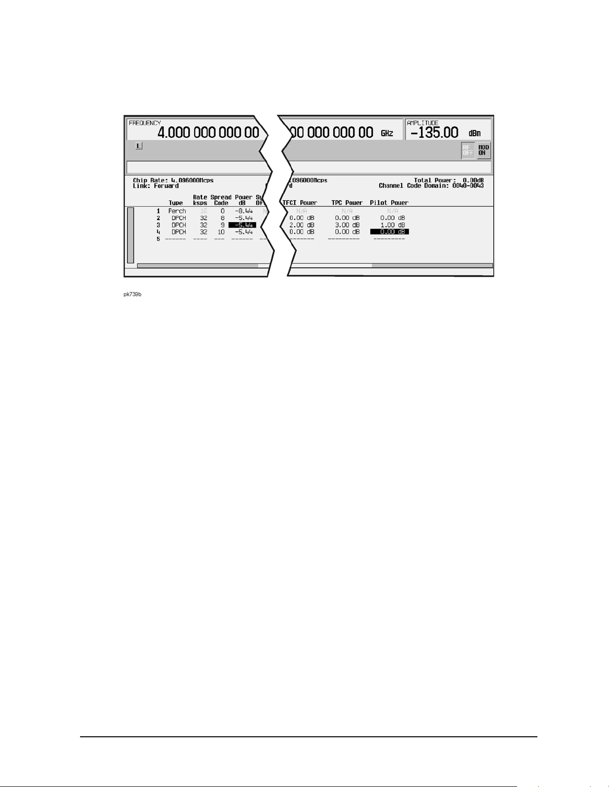
ESG Family Signal Generators Operation
Option 100 Understanding TFCI, TPC, and Pilot Power Offsets
Figure 4-7 Table Editor Showing TFCI, TPC, and Pilot Power Offsets
W-CDMA (Rev. 1.0-1.2) Personality User’s and Programming Guide 4-7
Page 98

Operation ESG Family Signal Generators
Understanding Baseband Clipping Option 100
Understanding Baseband Clipping
In a W-CDMA waveform, high power peaks can cause intermodulation distortion, which
generates spectral regrowth (a condition that interferes with signals in adjacent frequency
bands). The clipping function allows you to reduce high power peaks.
How Power Peaks Develop
To understand how clipping reduces high power peaks in a W-CDMA signal, it is important
to know how the peaks develop as the signal is constructed.
A W-CDMA waveform is composed of an I waveform and a Q waveform. Often, these
waveforms are the summation of multiple channels (refer to Figure 4-8). Whenever most or
all of the individual channel waveforms simultaneously contain a bit in the same state
(high or low), an unusually high power peak (negative or positive) occurs in the summed
waveform. This does not happen frequently because the high and low states of the bits on
these channel waveforms are random, which causes a cancelling effect.
Figure 4-8 Multiple Channel Summing
4-8
W-CDMA (Rev. 1.0-1.2) Personality User’s and Programming Guide
Page 99

ESG Family Signal Generators Operation
Option 100 Understanding Baseband Clipping
The I and Q waveforms combine in the I/Q modulator to create an RF waveform. The
magnitude of the RF envelope is determined by the equation , where the squaring of
I and Q always results in a positive value. Notice how simultaneous positive and negative
peaks in the I and Q waveforms do not cancel each other, but combine to create an even
greater peak (refer to Figure 4-9).
Figure 4-9 Combining the I and Q Waveforms
W-CDMA (Rev. 1.0-1.2) Personality User’s and Programming Guide 4-9
Page 100

Operation ESG Family Signal Generators
Understanding Baseband Clipping Option 100
How Peaks Cause Spectral Regrowth
Because of the relative infrequency of high power peaks, a waveform will have a high
peak-to-average power ratio (refer to Figure 4-10). Because a transmitter’s power amplifier
gain is set to provide a specific average power, high peaks can cause the power amplifier to
move toward saturation. This causes intermodulation distortion, which generates spectral
regrowth.
Figure 4-10 Peak-to-Average Power in the W-CDMA Waveform
Spectral regrowth is a range of frequencies that develops on each side of the carrier
(similar to sidebands) and extends into the adjacent frequency bands (refer to Figure 4-11).
Consequently, spectral regrowth interferes with communication in the adjacent bands.
Clipping can provide a solution to this problem.
Figure 4-11 Spectral Regrowth Interfering with Adjacent Band
4-10
W-CDMA (Rev. 1.0-1.2) Personality User’s and Programming Guide
 Loading...