

Page 1

User’s and Programming Guide
Agilent Technologies
ESG Family Signal Generators
Options:
UND, Dual Arbitrary Waveform Generator
UN5, Multichannel, Multicarrier CDMA Personality
Serial Number Pref i xes :
(Affix Label Here)
Part No. E4400-90328
Printed in USA
December 2005
Supersedes June 2001
© Copyright 1999-2005 Agilent Technologies
Page 2

ii
Page 3

Contents
1. The Dual Arbitrary Waveform Generator
Overviews . . . . . . . . . . . . . . . . . . . . . . . . . . . . . . . . . . . . . . . . . . . . . . . . . . . . . . . . . . . . . . . . . .1-2
Specifications. . . . . . . . . . . . . . . . . . . . . . . . . . . . . . . . . . . . . . . . . . . . . . . . . . . . . . . . . . . . . .1-2
Dual Arbitrary Waveform Generator (Option UND). . . . . . . . . . . . . . . . . . . . . . . . . . . . . . .1-2
Multichannel, Multicarrier CDMA Personality (Option UN5). . . . . . . . . . . . . . . . . . . . . . .1-4
2. Using F unctions
Table Editor Basics. . . . . . . . . . . . . . . . . . . . . . . . . . . . . . . . . . . . . . . . . . . . . . . . . . . . . . . . . . .2-2
Creating Custom CDMA States . . . . . . . . . . . . . . . . . . . . . . . . . . . . . . . . . . . . . . . . . . . . . . . .2-3
Setting up a CDMA Template . . . . . . . . . . . . . . . . . . . . . . . . . . . . . . . . . . . . . . . . . . . . . . . .2-3
Modifying a CDMA Template. . . . . . . . . . . . . . . . . . . . . . . . . . . . . . . . . . . . . . . . . . . . . . . . .2-4
Applying a Custom Channel Setup, then Activating the Custom CDMA State
and Applying it to the RF Output . . . . . . . . . . . . . . . . . . . . . . . . . . . . . . . . . . . . . . . . . . . . .2-7
Clipping a CDMA Waveform . . . . . . . . . . . . . . . . . . . . . . . . . . . . . . . . . . . . . . . . . . . . . . . . .2-8
Viewing Code Domain Power and Waveform Statistics . . . . . . . . . . . . . . . . . . . . . . . . . . . .2-9
Storing a Custom CDMA State to Memory. . . . . . . . . . . . . . . . . . . . . . . . . . . . . . . . . . . . . . .2-11
Recalling Custom CDMA States . . . . . . . . . . . . . . . . . . . . . . . . . . . . . . . . . . . . . . . . . . . . . . .2-13
Creating Custom Multicarrier CDMA Waveforms. . . . . . . . . . . . . . . . . . . . . . . . . . . . . . . . .2-15
Opening the Multicarrier CDMA Setup Table Editor. . . . . . . . . . . . . . . . . . . . . . . . . . . . .2-15
Modifying a Multicarrier CDMA 3-Carrier Template. . . . . . . . . . . . . . . . . . . . . . . . . . . . .2-17
Applying and Activating the Custom Multicarrier CDMA Setup . . . . . . . . . . . . . . . . . . .2-21
Applying the Custom Multicarrier CDMA Waveform to the RF Output. . . . . . . . . . . . . .2-22
Storing a Custom Multicarrier CDMA Waveform . . . . . . . . . . . . . . . . . . . . . . . . . . . . . . . . .2-23
Recalling Custom Multicarrier CDMA Waveforms . . . . . . . . . . . . . . . . . . . . . . . . . . . . . . . .2-25
Setting Up Predefined Single Carrier Digital Modulation . . . . . . . . . . . . . . . . . . . . . . . . . .2-27
Setting Up Custom Single Carrier Digital Modulation . . . . . . . . . . . . . . . . . . . . . . . . . . . . .2-29
Setting Up a Multicarrier Digital Modulation . . . . . . . . . . . . . . . . . . . . . . . . . . . . . . . . . . . .2-33
Creating a User-Defined FIR Filter Using the FIR Table Editor . . . . . . . . . . . . . . . . . . . . .2-35
Accessing the Table Editor . . . . . . . . . . . . . . . . . . . . . . . . . . . . . . . . . . . . . . . . . . . . . . . . . .2-35
Entering the Coefficient Values . . . . . . . . . . . . . . . . . . . . . . . . . . . . . . . . . . . . . . . . . . . . . .2-36
Duplicating the First 16 Coefficients Using Mirror Table . . . . . . . . . . . . . . . . . . . . . . . . .2-37
Setting the Oversample Ratio . . . . . . . . . . . . . . . . . . . . . . . . . . . . . . . . . . . . . . . . . . . . . . .2-37
Displaying a Graphical Representation of the Filter . . . . . . . . . . . . . . . . . . . . . . . . . . . . .2-38
Storing the Filter to Memory . . . . . . . . . . . . . . . . . . . . . . . . . . . . . . . . . . . . . . . . . . . . . . . .2-39
Modifying a FIR Filter Using the FIR Table Editor. . . . . . . . . . . . . . . . . . . . . . . . . . . . . . . .2-40
Loading a Default Gaussian FIR File . . . . . . . . . . . . . . . . . . . . . . . . . . . . . . . . . . . . . . . . .2-40
Modifying the Coefficients . . . . . . . . . . . . . . . . . . . . . . . . . . . . . . . . . . . . . . . . . . . . . . . . . .2-41
Storing the Filter to Memory . . . . . . . . . . . . . . . . . . . . . . . . . . . . . . . . . . . . . . . . . . . . . . . .2-42
Applying a User-Defined FIR Filter to a CDMA State . . . . . . . . . . . . . . . . . . . . . . . . . . . . .2-43
Using External Reconstruction Filters . . . . . . . . . . . . . . . . . . . . . . . . . . . . . . . . . . . . . . . . . .2-45
Using the Multitone Waveform Generator . . . . . . . . . . . . . . . . . . . . . . . . . . . . . . . . . . . . . . .2-46
Creating a Multitone Waveform. . . . . . . . . . . . . . . . . . . . . . . . . . . . . . . . . . . . . . . . . . . . . .2-47
Using a Stored Multitone Waveform . . . . . . . . . . . . . . . . . . . . . . . . . . . . . . . . . . . . . . . . . .2-52
Building a Waveform Sequence. . . . . . . . . . . . . . . . . . . . . . . . . . . . . . . . . . . . . . . . . . . . . . . .2-54
Generating the First Waveform . . . . . . . . . . . . . . . . . . . . . . . . . . . . . . . . . . . . . . . . . . . . . .2-54
Renaming the First Waveform as a Waveform Segment . . . . . . . . . . . . . . . . . . . . . . . . . .2-55
Generating the Second Waveform . . . . . . . . . . . . . . . . . . . . . . . . . . . . . . . . . . . . . . . . . . . .2-56
Renaming the Second Waveform as a Waveform Segment. . . . . . . . . . . . . . . . . . . . . . . . .2-56
Building a Waveform Sequence from Two Waveform Segments . . . . . . . . . . . . . . . . . . . .2-57
iii
Page 4

Contents
Editing the First and Second Waveform Segment Repetitions . . . . . . . . . . . . . . . . . . . . . 2-58
Naming and Storing the Waveform Sequence . . . . . . . . . . . . . . . . . . . . . . . . . . . . . . . . . . 2-59
Playing the Waveform Sequence . . . . . . . . . . . . . . . . . . . . . . . . . . . . . . . . . . . . . . . . . . . . . 2-60
Using Markers. . . . . . . . . . . . . . . . . . . . . . . . . . . . . . . . . . . . . . . . . . . . . . . . . . . . . . . . . . . . . 2-61
Placing Markers on a Waveform Segment . . . . . . . . . . . . . . . . . . . . . . . . . . . . . . . . . . . . . 2-61
Using Markers in a Waveform Sequence . . . . . . . . . . . . . . . . . . . . . . . . . . . . . . . . . . . . . . 2-65
Scaling Waveform Segments. . . . . . . . . . . . . . . . . . . . . . . . . . . . . . . . . . . . . . . . . . . . . . . . . . 2-68
Clipping Waveform Segments. . . . . . . . . . . . . . . . . . . . . . . . . . . . . . . . . . . . . . . . . . . . . . . . . 2-70
Downloading Waveform Files Into Memory. . . . . . . . . . . . . . . . . . . . . . . . . . . . . . . . . . . . . . 2-72
Downloading Waveform Files Into ARB Memory. . . . . . . . . . . . . . . . . . . . . . . . . . . . . . . . 2-72
Sample Command Line . . . . . . . . . . . . . . . . . . . . . . . . . . . . . . . . . . . . . . . . . . . . . . . . . . . . 2-72
Example 1 . . . . . . . . . . . . . . . . . . . . . . . . . . . . . . . . . . . . . . . . . . . . . . . . . . . . . . . . . . . . . . . 2-73
Querying the Waveform Data . . . . . . . . . . . . . . . . . . . . . . . . . . . . . . . . . . . . . . . . . . . . . . . 2-73
Waveform Downloading Using BASIC for Windows . . . . . . . . . . . . . . . . . . . . . . . . . . . . 2-73
Waveform Downloading HP BASIC for UNIX . . . . . . . . . . . . . . . . . . . . . . . . . . . . . . . . . . 2-75
Transferring Wa veforms Between ARB and NVARB Memory . . . . . . . . . . . . . . . . . . . . . 2-77
Selecting a Waveform and Activating the Modulation via GPIB . . . . . . . . . . . . . . . . . . . 2-78
Viewing Files Stored in the Memory Catalog . . . . . . . . . . . . . . . . . . . . . . . . . . . . . . . . . . . . 2-79
Creating Additive White Gaussian Noise (AWGN) Waveforms . . . . . . . . . . . . . . . . . . . . . . 2-80
Using Arbitrary Waveform Generator Triggers. . . . . . . . . . . . . . . . . . . . . . . . . . . . . . . . . . . 2-81
Creating an Externally Triggered Custom Multicarrier CDMA Waveform . . . . . . . . . . . 2-81
Controlling Waveform Sequence Playback Using Segment Advance Triggering. . . . . . . 2-86
Setting Up a Bluetooth Signal . . . . . . . . . . . . . . . . . . . . . . . . . . . . . . . . . . . . . . . . . . . . . . . . 2-93
Accessing the Bluetooth Setup Menu . . . . . . . . . . . . . . . . . . . . . . . . . . . . . . . . . . . . . . . . . 2-93
Setting Up Packet Parameters . . . . . . . . . . . . . . . . . . . . . . . . . . . . . . . . . . . . . . . . . . . . . . 2-93
Setting up Impairments. . . . . . . . . . . . . . . . . . . . . . . . . . . . . . . . . . . . . . . . . . . . . . . . . . . . 2-95
Using Burst . . . . . . . . . . . . . . . . . . . . . . . . . . . . . . . . . . . . . . . . . . . . . . . . . . . . . . . . . . . . . 2-96
Setting the Burst Power Ramp . . . . . . . . . . . . . . . . . . . . . . . . . . . . . . . . . . . . . . . . . . . . . . 2-97
Using Clock/Gate Delay . . . . . . . . . . . . . . . . . . . . . . . . . . . . . . . . . . . . . . . . . . . . . . . . . . . . 2-97
Turning On a Bluetooth Signal . . . . . . . . . . . . . . . . . . . . . . . . . . . . . . . . . . . . . . . . . . . . . . 2-97
3. Softkey Reference
Mode Key . . . . . . . . . . . . . . . . . . . . . . . . . . . . . . . . . . . . . . . . . . . . . . . . . . . . . . . . . . . . . . . . . . 3-2
p/4 DQPSK2 . . . . . . . . . . . . . . . . . . . . . . . . . . . . . . . . . . . . . . . . . . . . . . . . . . . . . . . . . . . . . . 3-3
# of Carriers . . . . . . . . . . . . . . . . . . . . . . . . . . . . . . . . . . . . . . . . . . . . . . . . . . . . . . . . . . . . . . 3-3
# Skipped Points. . . . . . . . . . . . . . . . . . . . . . . . . . . . . . . . . . . . . . . . . . . . . . . . . . . . . . . . . . . 3-3
2-Lvl FSK . . . . . . . . . . . . . . . . . . . . . . . . . . . . . . . . . . . . . . . . . . . . . . . . . . . . . . . . . . . . . . . . 3-4
2.500 MHz. . . . . . . . . . . . . . . . . . . . . . . . . . . . . . . . . . . . . . . . . . . . . . . . . . . . . . . . . . . . . . . . 3-4
4-Lvl FSK . . . . . . . . . . . . . . . . . . . . . . . . . . . . . . . . . . . . . . . . . . . . . . . . . . . . . . . . . . . . . . . . 3-4
4QAM . . . . . . . . . . . . . . . . . . . . . . . . . . . . . . . . . . . . . . . . . . . . . . . . . . . . . . . . . . . . . . . . . . . 3-4
8.000 MHz. . . . . . . . . . . . . . . . . . . . . . . . . . . . . . . . . . . . . . . . . . . . . . . . . . . . . . . . . . . . . . . . 3-4
8 Bit Pattern. . . . . . . . . . . . . . . . . . . . . . . . . . . . . . . . . . . . . . . . . . . . . . . . . . . . . . . . . . . . . . 3-5
8-Lvl FSK . . . . . . . . . . . . . . . . . . . . . . . . . . . . . . . . . . . . . . . . . . . . . . . . . . . . . . . . . . . . . . . . 3-5
8PSK . . . . . . . . . . . . . . . . . . . . . . . . . . . . . . . . . . . . . . . . . . . . . . . . . . . . . . . . . . . . . . . . . . . . 3-5
9 Ch Fwd. . . . . . . . . . . . . . . . . . . . . . . . . . . . . . . . . . . . . . . . . . . . . . . . . . . . . . . . . . . . . . . . . 3-5
16-Lvl FSK . . . . . . . . . . . . . . . . . . . . . . . . . . . . . . . . . . . . . . . . . . . . . . . . . . . . . . . . . . . . . . . 3-6
16PSK . . . . . . . . . . . . . . . . . . . . . . . . . . . . . . . . . . . . . . . . . . . . . . . . . . . . . . . . . . . . . . . . . . . 3-6
16QAM . . . . . . . . . . . . . . . . . . . . . . . . . . . . . . . . . . . . . . . . . . . . . . . . . . . . . . . . . . . . . . . . . . 3-6
32 Ch Fwd. . . . . . . . . . . . . . . . . . . . . . . . . . . . . . . . . . . . . . . . . . . . . . . . . . . . . . . . . . . . . . . . 3-6
iv
Page 5

Contents
32QAM. . . . . . . . . . . . . . . . . . . . . . . . . . . . . . . . . . . . . . . . . . . . . . . . . . . . . . . . . . . . . . . . . . .3-7
64 Ch Fwd . . . . . . . . . . . . . . . . . . . . . . . . . . . . . . . . . . . . . . . . . . . . . . . . . . . . . . . . . . . . . . . .3-7
64QAM. . . . . . . . . . . . . . . . . . . . . . . . . . . . . . . . . . . . . . . . . . . . . . . . . . . . . . . . . . . . . . . . . . .3-7
250.0 kHz. . . . . . . . . . . . . . . . . . . . . . . . . . . . . . . . . . . . . . . . . . . . . . . . . . . . . . . . . . . . . . . . .3-7
256QAM. . . . . . . . . . . . . . . . . . . . . . . . . . . . . . . . . . . . . . . . . . . . . . . . . . . . . . . . . . . . . . . . . .3-8
16384 . . . . . . . . . . . . . . . . . . . . . . . . . . . . . . . . . . . . . . . . . . . . . . . . . . . . . . . . . . . . . . . . . . . .3-8
32768 . . . . . . . . . . . . . . . . . . . . . . . . . . . . . . . . . . . . . . . . . . . . . . . . . . . . . . . . . . . . . . . . . . . .3-8
65536 . . . . . . . . . . . . . . . . . . . . . . . . . . . . . . . . . . . . . . . . . . . . . . . . . . . . . . . . . . . . . . . . . . . .3-8
131072 . . . . . . . . . . . . . . . . . . . . . . . . . . . . . . . . . . . . . . . . . . . . . . . . . . . . . . . . . . . . . . . . . . .3-8
262144 . . . . . . . . . . . . . . . . . . . . . . . . . . . . . . . . . . . . . . . . . . . . . . . . . . . . . . . . . . . . . . . . . . .3-8
524288 . . . . . . . . . . . . . . . . . . . . . . . . . . . . . . . . . . . . . . . . . . . . . . . . . . . . . . . . . . . . . . . . . . .3-8
1048576 . . . . . . . . . . . . . . . . . . . . . . . . . . . . . . . . . . . . . . . . . . . . . . . . . . . . . . . . . . . . . . . . . .3-8
Adjust Code Domain Power . . . . . . . . . . . . . . . . . . . . . . . . . . . . . . . . . . . . . . . . . . . . . . . . . .3-9
AM_ADDR. . . . . . . . . . . . . . . . . . . . . . . . . . . . . . . . . . . . . . . . . . . . . . . . . . . . . . . . . . . . . . . .3-9
APCO 25 C4FM. . . . . . . . . . . . . . . . . . . . . . . . . . . . . . . . . . . . . . . . . . . . . . . . . . . . . . . . . . . .3-9
APCO 25 w/C4FM. . . . . . . . . . . . . . . . . . . . . . . . . . . . . . . . . . . . . . . . . . . . . . . . . . . . . . . . . .3-9
APCO 25 w/CQPSK. . . . . . . . . . . . . . . . . . . . . . . . . . . . . . . . . . . . . . . . . . . . . . . . . . . . . . . .3-10
Apply Channel Setup . . . . . . . . . . . . . . . . . . . . . . . . . . . . . . . . . . . . . . . . . . . . . . . . . . . . . .3-10
Apply Multicarrier . . . . . . . . . . . . . . . . . . . . . . . . . . . . . . . . . . . . . . . . . . . . . . . . . . . . . . . . 3 -10
Apply Multitone . . . . . . . . . . . . . . . . . . . . . . . . . . . . . . . . . . . . . . . . . . . . . . . . . . . . . . . . . .3-10
Apply to Waveform . . . . . . . . . . . . . . . . . . . . . . . . . . . . . . . . . . . . . . . . . . . . . . . . . . . . . . . .3-11
ARB Off On . . . . . . . . . . . . . . . . . . . . . . . . . . . . . . . . . . . . . . . . . . . . . . . . . . . . . . . . . . . . . .3-12
ARB Reference Ext Int . . . . . . . . . . . . . . . . . . . . . . . . . . . . . . . . . . . . . . . . . . . . . . . . . . . . .3-12
ARB Sample Clock . . . . . . . . . . . . . . . . . . . . . . . . . . . . . . . . . . . . . . . . . . . . . . . . . . . . . . . .3-12
ARB Setup. . . . . . . . . . . . . . . . . . . . . . . . . . . . . . . . . . . . . . . . . . . . . . . . . . . . . . . . . . . . . . .3-12
AWGN . . . . . . . . . . . . . . . . . . . . . . . . . . . . . . . . . . . . . . . . . . . . . . . . . . . . . . . . . . . . . . . . . .3-13
AWGN Off On . . . . . . . . . . . . . . . . . . . . . . . . . . . . . . . . . . . . . . . . . . . . . . . . . . . . . . . . . . . .3-13
Bandwidth. . . . . . . . . . . . . . . . . . . . . . . . . . . . . . . . . . . . . . . . . . . . . . . . . . . . . . . . . . . . . . .3-13
BD_ADDR . . . . . . . . . . . . . . . . . . . . . . . . . . . . . . . . . . . . . . . . . . . . . . . . . . . . . . . . . . . . . . .3-14
Beta . . . . . . . . . . . . . . . . . . . . . . . . . . . . . . . . . . . . . . . . . . . . . . . . . . . . . . . . . . . . . . . . . . . .3-14
Bluetooth . . . . . . . . . . . . . . . . . . . . . . . . . . . . . . . . . . . . . . . . . . . . . . . . . . . . . . . . . . . . . . .3-14
Bluetooth Off On. . . . . . . . . . . . . . . . . . . . . . . . . . . . . . . . . . . . . . . . . . . . . . . . . . . . . . . . . .3-14
BPSK . . . . . . . . . . . . . . . . . . . . . . . . . . . . . . . . . . . . . . . . . . . . . . . . . . . . . . . . . . . . . . . . . . .3-15
Build New Waveform Sequence . . . . . . . . . . . . . . . . . . . . . . . . . . . . . . . . . . . . . . . . . . . . . .3-15
Burst Off On . . . . . . . . . . . . . . . . . . . . . . . . . . . . . . . . . . . . . . . . . . . . . . . . . . . . . . . . . . . . .3-15
Burst Power Ramp . . . . . . . . . . . . . . . . . . . . . . . . . . . . . . . . . . . . . . . . . . . . . . . . . . . . . . . .3-15
Bus. . . . . . . . . . . . . . . . . . . . . . . . . . . . . . . . . . . . . . . . . . . . . . . . . . . . . . . . . . . . . . . . . . . . .3-16
C4FM . . . . . . . . . . . . . . . . . . . . . . . . . . . . . . . . . . . . . . . . . . . . . . . . . . . . . . . . . . . . . . . . . . .3-16
Carrier Phases Fixed Random . . . . . . . . . . . . . . . . . . . . . . . . . . . . . . . . . . . . . . . . . . . . . . .3-16
Carrier Setup. . . . . . . . . . . . . . . . . . . . . . . . . . . . . . . . . . . . . . . . . . . . . . . . . . . . . . . . . . . . .3-16
CDMA Define . . . . . . . . . . . . . . . . . . . . . . . . . . . . . . . . . . . . . . . . . . . . . . . . . . . . . . . . . . . .3-17
CDMA Formats . . . . . . . . . . . . . . . . . . . . . . . . . . . . . . . . . . . . . . . . . . . . . . . . . . . . . . . . . . .3-17
CDMA Off On . . . . . . . . . . . . . . . . . . . . . . . . . . . . . . . . . . . . . . . . . . . . . . . . . . . . . . . . . . . .3-17
CDPD. . . . . . . . . . . . . . . . . . . . . . . . . . . . . . . . . . . . . . . . . . . . . . . . . . . . . . . . . . . . . . . . . . .3-17
Chip Rate. . . . . . . . . . . . . . . . . . . . . . . . . . . . . . . . . . . . . . . . . . . . . . . . . . . . . . . . . . . . . . . .3-17
Clip |I+jQ| To. . . . . . . . . . . . . . . . . . . . . . . . . . . . . . . . . . . . . . . . . . . . . . . . . . . . . . . . . . . .3-18
Clip |I| To. . . . . . . . . . . . . . . . . . . . . . . . . . . . . . . . . . . . . . . . . . . . . . . . . . . . . . . . . . . . . . .3-18
Clip |Q| To . . . . . . . . . . . . . . . . . . . . . . . . . . . . . . . . . . . . . . . . . . . . . . . . . . . . . . . . . . . . . .3-18
Clip At PRE POST FIR Filter . . . . . . . . . . . . . . . . . . . . . . . . . . . . . . . . . . . . . . . . . . . . . . .3-19
v
Page 6

Contents
Clipping. . . . . . . . . . . . . . . . . . . . . . . . . . . . . . . . . . . . . . . . . . . . . . . . . . . . . . . . . . . . . . . . . 3-19
Clipping Type |I+jQ| |I|,|Q| . . . . . . . . . . . . . . . . . . . . . . . . . . . . . . . . . . . . . . . . . . . . . . 3-19
Clock/Gate Delay . . . . . . . . . . . . . . . . . . . . . . . . . . . . . . . . . . . . . . . . . . . . . . . . . . . . . . . . . 3-20
C/N [1 MHz] . . . . . . . . . . . . . . . . . . . . . . . . . . . . . . . . . . . . . . . . . . . . . . . . . . . . . . . . . . . . . 3-20
Continuous . . . . . . . . . . . . . . . . . . . . . . . . . . . . . . . . . . . . . . . . . . . . . . . . . . . . . . . . . . . . . . 3-20
Continuous PN9 . . . . . . . . . . . . . . . . . . . . . . . . . . . . . . . . . . . . . . . . . . . . . . . . . . . . . . . . . .3-21
Custom CDMA Carrier . . . . . . . . . . . . . . . . . . . . . . . . . . . . . . . . . . . . . . . . . . . . . . . . . . . . 3-21
Custom CDMA Multicarrier . . . . . . . . . . . . . . . . . . . . . . . . . . . . . . . . . . . . . . . . . . . . . . . . 3-21
Custom CDMA State . . . . . . . . . . . . . . . . . . . . . . . . . . . . . . . . . . . . . . . . . . . . . . . . . . . . . . 3-21
Custom Digital Mod State . . . . . . . . . . . . . . . . . . . . . . . . . . . . . . . . . . . . . . . . . . . . . . . . . . 3-22
D8PSK. . . . . . . . . . . . . . . . . . . . . . . . . . . . . . . . . . . . . . . . . . . . . . . . . . . . . . . . . . . . . . . . . . 3-22
DECT. . . . . . . . . . . . . . . . . . . . . . . . . . . . . . . . . . . . . . . . . . . . . . . . . . . . . . . . . . . . . . . . . . . 3-22
Define User FIR . . . . . . . . . . . . . . . . . . . . . . . . . . . . . . . . . . . . . . . . . . . . . . . . . . . . . . . . . . 3-22
Delete All ARB Files . . . . . . . . . . . . . . . . . . . . . . . . . . . . . . . . . . . . . . . . . . . . . . . . . . . . . .3-23
Delete All NVARB Files. . . . . . . . . . . . . . . . . . . . . . . . . . . . . . . . . . . . . . . . . . . . . . . . . . . . 3-23
Delete All Rows . . . . . . . . . . . . . . . . . . . . . . . . . . . . . . . . . . . . . . . . . . . . . . . . . . . . . . . . . . 3-2 3
Delete File. . . . . . . . . . . . . . . . . . . . . . . . . . . . . . . . . . . . . . . . . . . . . . . . . . . . . . . . . . . . . . . 3-23
Delete Row . . . . . . . . . . . . . . . . . . . . . . . . . . . . . . . . . . . . . . . . . . . . . . . . . . . . . . . . . . . . . . 3-23
Delete Segment. . . . . . . . . . . . . . . . . . . . . . . . . . . . . . . . . . . . . . . . . . . . . . . . . . . . . . . . . . . 3-24
Delete Selected Waveform . . . . . . . . . . . . . . . . . . . . . . . . . . . . . . . . . . . . . . . . . . . . . . . . . . 3-24
Delete Waveform Sequence . . . . . . . . . . . . . . . . . . . . . . . . . . . . . . . . . . . . . . . . . . . . . . . . . 3-24
Digital Mod Define . . . . . . . . . . . . . . . . . . . . . . . . . . . . . . . . . . . . . . . . . . . . . . . . . . . . . . . .3-24
Digital Modulation Off On. . . . . . . . . . . . . . . . . . . . . . . . . . . . . . . . . . . . . . . . . . . . . . . . . . 3-24
Display Code Domain Power . . . . . . . . . . . . . . . . . . . . . . . . . . . . . . . . . . . . . . . . . . . . . . . . 3-25
Display FFT . . . . . . . . . . . . . . . . . . . . . . . . . . . . . . . . . . . . . . . . . . . . . . . . . . . . . . . . . . . . . 3-26
Display Impulse Response. . . . . . . . . . . . . . . . . . . . . . . . . . . . . . . . . . . . . . . . . . . . . . . . . . 3-26
Done . . . . . . . . . . . . . . . . . . . . . . . . . . . . . . . . . . . . . . . . . . . . . . . . . . . . . . . . . . . . . . . . . . . 3-27
Done Inserting . . . . . . . . . . . . . . . . . . . . . . . . . . . . . . . . . . . . . . . . . . . . . . . . . . . . . . . . . . . 3-27
Drift Deviation . . . . . . . . . . . . . . . . . . . . . . . . . . . . . . . . . . . . . . . . . . . . . . . . . . . . . . . . . . . 3-27
Dual Arb . . . . . . . . . . . . . . . . . . . . . . . . . . . . . . . . . . . . . . . . . . . . . . . . . . . . . . . . . . . . . . . . 3-27
EDGE . . . . . . . . . . . . . . . . . . . . . . . . . . . . . . . . . . . . . . . . . . . . . . . . . . . . . . . . . . . . . . . . . . 3-28
Edit Channel Setup . . . . . . . . . . . . . . . . . . . . . . . . . . . . . . . . . . . . . . . . . . . . . . . . . . . . . . .3-28
Edit Item. . . . . . . . . . . . . . . . . . . . . . . . . . . . . . . . . . . . . . . . . . . . . . . . . . . . . . . . . . . . . . . . 3-28
Edit Repetitions . . . . . . . . . . . . . . . . . . . . . . . . . . . . . . . . . . . . . . . . . . . . . . . . . . . . . . . . . . 3-29
Edit Selected Waveform Sequence . . . . . . . . . . . . . . . . . . . . . . . . . . . . . . . . . . . . . . . . . . . 3-29
Enter . . . . . . . . . . . . . . . . . . . . . . . . . . . . . . . . . . . . . . . . . . . . . . . . . . . . . . . . . . . . . . . . . . . 3-29
Equal Powers . . . . . . . . . . . . . . . . . . . . . . . . . . . . . . . . . . . . . . . . . . . . . . . . . . . . . . . . . . . . 3-29
Ext. . . . . . . . . . . . . . . . . . . . . . . . . . . . . . . . . . . . . . . . . . . . . . . . . . . . . . . . . . . . . . . . . . . . . 3-29
Ext Delay Off On . . . . . . . . . . . . . . . . . . . . . . . . . . . . . . . . . . . . . . . . . . . . . . . . . . . . . . . . . 3-30
Ext Delay Time. . . . . . . . . . . . . . . . . . . . . . . . . . . . . . . . . . . . . . . . . . . . . . . . . . . . . . . . . . . 3-30
Ext Polarity Neg Pos . . . . . . . . . . . . . . . . . . . . . . . . . . . . . . . . . . . . . . . . . . . . . . . . . . . . . .3-31
Filter . . . . . . . . . . . . . . . . . . . . . . . . . . . . . . . . . . . . . . . . . . . . . . . . . . . . . . . . . . . . . . . . . . . 3-31
Filter Alpha . . . . . . . . . . . . . . . . . . . . . . . . . . . . . . . . . . . . . . . . . . . . . . . . . . . . . . . . . . . . . 3-31
Filter BbT . . . . . . . . . . . . . . . . . . . . . . . . . . . . . . . . . . . . . . . . . . . . . . . . . . . . . . . . . . . . . . . 3-32
Filter Factor N/A . . . . . . . . . . . . . . . . . . . . . . . . . . . . . . . . . . . . . . . . . . . . . . . . . . . . . . . . . 3 -3 3
Filter Symbols . . . . . . . . . . . . . . . . . . . . . . . . . . . . . . . . . . . . . . . . . . . . . . . . . . . . . . . . . . . 3 -33
First Mkr Point. . . . . . . . . . . . . . . . . . . . . . . . . . . . . . . . . . . . . . . . . . . . . . . . . . . . . . . . . . . 3-33
Freq Dev . . . . . . . . . . . . . . . . . . . . . . . . . . . . . . . . . . . . . . . . . . . . . . . . . . . . . . . . . . . . . . . . 3-34
Freq Drift Type
vi
Page 7

Contents
Linear Sine . . . . . . . . . . . . . . . . . . . . . . . . . . . . . . . . . . . . . . . . . . . . . . . . . . . . . . . . . . . . . .3-35
Freq Offset. . . . . . . . . . . . . . . . . . . . . . . . . . . . . . . . . . . . . . . . . . . . . . . . . . . . . . . . . . . . . . .3-36
Freq Spacing . . . . . . . . . . . . . . . . . . . . . . . . . . . . . . . . . . . . . . . . . . . . . . . . . . . . . . . . . . . . .3-36
FSK . . . . . . . . . . . . . . . . . . . . . . . . . . . . . . . . . . . . . . . . . . . . . . . . . . . . . . . . . . . . . . . . . . . .3-36
Gate Active Low High. . . . . . . . . . . . . . . . . . . . . . . . . . . . . . . . . . . . . . . . . . . . . . . . . . . . . .3-37
Gate Active N/A. . . . . . . . . . . . . . . . . . . . . . . . . . . . . . . . . . . . . . . . . . . . . . . . . . . . . . . . . . .3-37
Gated . . . . . . . . . . . . . . . . . . . . . . . . . . . . . . . . . . . . . . . . . . . . . . . . . . . . . . . . . . . . . . . . . . .3-37
Gaussian . . . . . . . . . . . . . . . . . . . . . . . . . . . . . . . . . . . . . . . . . . . . . . . . . . . . . . . . . . . . . . . .3-38
Generate . . . . . . . . . . . . . . . . . . . . . . . . . . . . . . . . . . . . . . . . . . . . . . . . . . . . . . . . . . . . . . . .3-38
Goto Bottom Row . . . . . . . . . . . . . . . . . . . . . . . . . . . . . . . . . . . . . . . . . . . . . . . . . . . . . . . . .3-39
Goto Middle Row. . . . . . . . . . . . . . . . . . . . . . . . . . . . . . . . . . . . . . . . . . . . . . . . . . . . . . . . . .3-39
Goto Row . . . . . . . . . . . . . . . . . . . . . . . . . . . . . . . . . . . . . . . . . . . . . . . . . . . . . . . . . . . . . . . .3-39
Goto Top Row. . . . . . . . . . . . . . . . . . . . . . . . . . . . . . . . . . . . . . . . . . . . . . . . . . . . . . . . . . . . .3-39
Gray Coded QPSK. . . . . . . . . . . . . . . . . . . . . . . . . . . . . . . . . . . . . . . . . . . . . . . . . . . . . . . . .3-39
GSM. . . . . . . . . . . . . . . . . . . . . . . . . . . . . . . . . . . . . . . . . . . . . . . . . . . . . . . . . . . . . . . . . . . .3-39
Hamming. . . . . . . . . . . . . . . . . . . . . . . . . . . . . . . . . . . . . . . . . . . . . . . . . . . . . . . . . . . . . . . .3-40
Hann . . . . . . . . . . . . . . . . . . . . . . . . . . . . . . . . . . . . . . . . . . . . . . . . . . . . . . . . . . . . . . . . . . .3-40
Impairments . . . . . . . . . . . . . . . . . . . . . . . . . . . . . . . . . . . . . . . . . . . . . . . . . . . . . . . . . . . . .3-40
Impairments Off On . . . . . . . . . . . . . . . . . . . . . . . . . . . . . . . . . . . . . . . . . . . . . . . . . . . . . . .3-40
Initialize Phase Fixed Random . . . . . . . . . . . . . . . . . . . . . . . . . . . . . . . . . . . . . . . . . . . . . .3-40
Initialize Table . . . . . . . . . . . . . . . . . . . . . . . . . . . . . . . . . . . . . . . . . . . . . . . . . . . . . . . . . . .3-41
Insert Row . . . . . . . . . . . . . . . . . . . . . . . . . . . . . . . . . . . . . . . . . . . . . . . . . . . . . . . . . . . . . . .3-41
Insert Selected Waveform. . . . . . . . . . . . . . . . . . . . . . . . . . . . . . . . . . . . . . . . . . . . . . . . . . .3-41
Insert Waveform . . . . . . . . . . . . . . . . . . . . . . . . . . . . . . . . . . . . . . . . . . . . . . . . . . . . . . . . . .3-41
Insert Wa veform Sequence Contents. . . . . . . . . . . . . . . . . . . . . . . . . . . . . . . . . . . . . . . . . .3-42
IS-95. . . . . . . . . . . . . . . . . . . . . . . . . . . . . . . . . . . . . . . . . . . . . . . . . . . . . . . . . . . . . . . . . . . .3-42
IS-95 and IS-2000 . . . . . . . . . . . . . . . . . . . . . . . . . . . . . . . . . . . . . . . . . . . . . . . . . . . . . . . . .3-42
IS-95A . . . . . . . . . . . . . . . . . . . . . . . . . . . . . . . . . . . . . . . . . . . . . . . . . . . . . . . . . . . . . . . . . .3-42
IS-95 Mod . . . . . . . . . . . . . . . . . . . . . . . . . . . . . . . . . . . . . . . . . . . . . . . . . . . . . . . . . . . . . . .3-43
IS-95 Mod w/EQ . . . . . . . . . . . . . . . . . . . . . . . . . . . . . . . . . . . . . . . . . . . . . . . . . . . . . . . . . .3-43
IS95 OQPSK . . . . . . . . . . . . . . . . . . . . . . . . . . . . . . . . . . . . . . . . . . . . . . . . . . . . . . . . . . . . .3-43
IS95 QPSK. . . . . . . . . . . . . . . . . . . . . . . . . . . . . . . . . . . . . . . . . . . . . . . . . . . . . . . . . . . . . . .3-44
IS-95 w/EQ. . . . . . . . . . . . . . . . . . . . . . . . . . . . . . . . . . . . . . . . . . . . . . . . . . . . . . . . . . . . . . .3-44
IS-97 Levels. . . . . . . . . . . . . . . . . . . . . . . . . . . . . . . . . . . . . . . . . . . . . . . . . . . . . . . . . . . . . .3-44
IS-2000 SR3 DS. . . . . . . . . . . . . . . . . . . . . . . . . . . . . . . . . . . . . . . . . . . . . . . . . . . . . . . . . . .3-44
Kaiser. . . . . . . . . . . . . . . . . . . . . . . . . . . . . . . . . . . . . . . . . . . . . . . . . . . . . . . . . . . . . . . . . . .3-44
Last Mkr Point . . . . . . . . . . . . . . . . . . . . . . . . . . . . . . . . . . . . . . . . . . . . . . . . . . . . . . . . . . .3-45
Load Default FIR . . . . . . . . . . . . . . . . . . . . . . . . . . . . . . . . . . . . . . . . . . . . . . . . . . . . . . . . .3-46
Load From Selected File . . . . . . . . . . . . . . . . . . . . . . . . . . . . . . . . . . . . . . . . . . . . . . . . . . . .3-46
Load Store . . . . . . . . . . . . . . . . . . . . . . . . . . . . . . . . . . . . . . . . . . . . . . . . . . . . . . . . . . . . . . .3-46
Load/Store . . . . . . . . . . . . . . . . . . . . . . . . . . . . . . . . . . . . . . . . . . . . . . . . . . . . . . . . . . . . . . .3-46
Marker 1 2. . . . . . . . . . . . . . . . . . . . . . . . . . . . . . . . . . . . . . . . . . . . . . . . . . . . . . . . . . . . . .3-47
Marker Polarity Neg Pos . . . . . . . . . . . . . . . . . . . . . . . . . . . . . . . . . . . . . . . . . . . . . . . . . . .3-47
Mirror Table . . . . . . . . . . . . . . . . . . . . . . . . . . . . . . . . . . . . . . . . . . . . . . . . . . . . . . . . . . . . .3-47
Mkr 2 To RF Blank Off On . . . . . . . . . . . . . . . . . . . . . . . . . . . . . . . . . . . . . . . . . . . . . . . . . .3-47
Mod Index . . . . . . . . . . . . . . . . . . . . . . . . . . . . . . . . . . . . . . . . . . . . . . . . . . . . . . . . . . . . . . .3-48
Modulation Type . . . . . . . . . . . . . . . . . . . . . . . . . . . . . . . . . . . . . . . . . . . . . . . . . . . . . . . . . .3-48
MSK. . . . . . . . . . . . . . . . . . . . . . . . . . . . . . . . . . . . . . . . . . . . . . . . . . . . . . . . . . . . . . . . . . . .3-48
MTONE . . . . . . . . . . . . . . . . . . . . . . . . . . . . . . . . . . . . . . . . . . . . . . . . . . . . . . . . . . . . . . . . .3-48
vii
Page 8

Contents
Multicarrier Define . . . . . . . . . . . . . . . . . . . . . . . . . . . . . . . . . . . . . . . . . . . . . . . . . . . . . . .3-48
Multicarrier Off On . . . . . . . . . . . . . . . . . . . . . . . . . . . . . . . . . . . . . . . . . . . . . . . . . . . . . . .3-49
Multitone . . . . . . . . . . . . . . . . . . . . . . . . . . . . . . . . . . . . . . . . . . . . . . . . . . . . . . . . . . . . . . . 3-49
Multitone Off On . . . . . . . . . . . . . . . . . . . . . . . . . . . . . . . . . . . . . . . . . . . . . . . . . . . . . . . . . 3-49
NADC . . . . . . . . . . . . . . . . . . . . . . . . . . . . . . . . . . . . . . . . . . . . . . . . . . . . . . . . . . . . . . . . . . 3-49
Name And Store . . . . . . . . . . . . . . . . . . . . . . . . . . . . . . . . . . . . . . . . . . . . . . . . . . . . . . . . . .3-50
Next PN Offset . . . . . . . . . . . . . . . . . . . . . . . . . . . . . . . . . . . . . . . . . . . . . . . . . . . . . . . . . . . 3-5 0
Noise Seed . . . . . . . . . . . . . . . . . . . . . . . . . . . . . . . . . . . . . . . . . . . . . . . . . . . . . . . . . . . . . . 3-50
Noise Seed Fixed Random . . . . . . . . . . . . . . . . . . . . . . . . . . . . . . . . . . . . . . . . . . . . . . . . . . 3-50
None . . . . . . . . . . . . . . . . . . . . . . . . . . . . . . . . . . . . . . . . . . . . . . . . . . . . . . . . . . . . . . . . . . . 3-50
Number of Tones. . . . . . . . . . . . . . . . . . . . . . . . . . . . . . . . . . . . . . . . . . . . . . . . . . . . . . . . . . 3-51
Nyquist . . . . . . . . . . . . . . . . . . . . . . . . . . . . . . . . . . . . . . . . . . . . . . . . . . . . . . . . . . . . . . . . . 3-51
Optimize FIR For EVM ACP . . . . . . . . . . . . . . . . . . . . . . . . . . . . . . . . . . . . . . . . . . . . . . . . 3-52
OQPSK . . . . . . . . . . . . . . . . . . . . . . . . . . . . . . . . . . . . . . . . . . . . . . . . . . . . . . . . . . . . . . . . . 3-52
Oversample Ratio. . . . . . . . . . . . . . . . . . . . . . . . . . . . . . . . . . . . . . . . . . . . . . . . . . . . . . . . .3-52
Packet (DH1). . . . . . . . . . . . . . . . . . . . . . . . . . . . . . . . . . . . . . . . . . . . . . . . . . . . . . . . . . . . . 3-53
Page Down . . . . . . . . . . . . . . . . . . . . . . . . . . . . . . . . . . . . . . . . . . . . . . . . . . . . . . . . . . . . . . 3-53
Page Up. . . . . . . . . . . . . . . . . . . . . . . . . . . . . . . . . . . . . . . . . . . . . . . . . . . . . . . . . . . . . . . . . 3-53
Paging . . . . . . . . . . . . . . . . . . . . . . . . . . . . . . . . . . . . . . . . . . . . . . . . . . . . . . . . . . . . . . . . . . 3-53
Payload Data. . . . . . . . . . . . . . . . . . . . . . . . . . . . . . . . . . . . . . . . . . . . . . . . . . . . . . . . . . . . . 3-54
PDC. . . . . . . . . . . . . . . . . . . . . . . . . . . . . . . . . . . . . . . . . . . . . . . . . . . . . . . . . . . . . . . . . . . . 3-54
PHS. . . . . . . . . . . . . . . . . . . . . . . . . . . . . . . . . . . . . . . . . . . . . . . . . . . . . . . . . . . . . . . . . . . . 3-54
Pilot (Setup Select). . . . . . . . . . . . . . . . . . . . . . . . . . . . . . . . . . . . . . . . . . . . . . . . . . . . . . . . 3-54
Plot CCDF. . . . . . . . . . . . . . . . . . . . . . . . . . . . . . . . . . . . . . . . . . . . . . . . . . . . . . . . . . . . . . . 3-55
PN Offset. . . . . . . . . . . . . . . . . . . . . . . . . . . . . . . . . . . . . . . . . . . . . . . . . . . . . . . . . . . . . . . . 3-55
Previous PN Offset. . . . . . . . . . . . . . . . . . . . . . . . . . . . . . . . . . . . . . . . . . . . . . . . . . . . . . . .3-56
Primary Key . . . . . . . . . . . . . . . . . . . . . . . . . . . . . . . . . . . . . . . . . . . . . . . . . . . . . . . . . . . . . 3-56
PSK . . . . . . . . . . . . . . . . . . . . . . . . . . . . . . . . . . . . . . . . . . . . . . . . . . . . . . . . . . . . . . . . . . . . 3-56
PWT. . . . . . . . . . . . . . . . . . . . . . . . . . . . . . . . . . . . . . . . . . . . . . . . . . . . . . . . . . . . . . . . . . . . 3-56
QAM . . . . . . . . . . . . . . . . . . . . . . . . . . . . . . . . . . . . . . . . . . . . . . . . . . . . . . . . . . . . . . . . . . . 3-56
QPSK. . . . . . . . . . . . . . . . . . . . . . . . . . . . . . . . . . . . . . . . . . . . . . . . . . . . . . . . . . . . . . . . . . . 3-57
QPSK and OQPSK . . . . . . . . . . . . . . . . . . . . . . . . . . . . . . . . . . . . . . . . . . . . . . . . . . . . . . . . 3-57
Random. . . . . . . . . . . . . . . . . . . . . . . . . . . . . . . . . . . . . . . . . . . . . . . . . . . . . . . . . . . . . . . . . 3-57
Random Seed Fixed Random. . . . . . . . . . . . . . . . . . . . . . . . . . . . . . . . . . . . . . . . . . . . . . . . 3-57
Reconstruction Filter . . . . . . . . . . . . . . . . . . . . . . . . . . . . . . . . . . . . . . . . . . . . . . . . . . . . . .3-58
Rectangle . . . . . . . . . . . . . . . . . . . . . . . . . . . . . . . . . . . . . . . . . . . . . . . . . . . . . . . . . . . . . . . 3-58
Reference Freq . . . . . . . . . . . . . . . . . . . . . . . . . . . . . . . . . . . . . . . . . . . . . . . . . . . . . . . . . . . 3 -58
Rename Segment . . . . . . . . . . . . . . . . . . . . . . . . . . . . . . . . . . . . . . . . . . . . . . . . . . . . . . . . .3-59
Restore Default Filter . . . . . . . . . . . . . . . . . . . . . . . . . . . . . . . . . . . . . . . . . . . . . . . . . . . . .3-59
Retrigger Mode Off On. . . . . . . . . . . . . . . . . . . . . . . . . . . . . . . . . . . . . . . . . . . . . . . . . . . . . 3-59
Reverse . . . . . . . . . . . . . . . . . . . . . . . . . . . . . . . . . . . . . . . . . . . . . . . . . . . . . . . . . . . . . . . . . 3-60
Root Nyquist. . . . . . . . . . . . . . . . . . . . . . . . . . . . . . . . . . . . . . . . . . . . . . . . . . . . . . . . . . . . . 3-60
Scale To 0dB . . . . . . . . . . . . . . . . . . . . . . . . . . . . . . . . . . . . . . . . . . . . . . . . . . . . . . . . . . . . . 3-61
Scaling. . . . . . . . . . . . . . . . . . . . . . . . . . . . . . . . . . . . . . . . . . . . . . . . . . . . . . . . . . . . . . . . . . 3-61
Secondary Key . . . . . . . . . . . . . . . . . . . . . . . . . . . . . . . . . . . . . . . . . . . . . . . . . . . . . . . . . . . 3-6 1
Segment Advance . . . . . . . . . . . . . . . . . . . . . . . . . . . . . . . . . . . . . . . . . . . . . . . . . . . . . . . . .3-61
Select. . . . . . . . . . . . . . . . . . . . . . . . . . . . . . . . . . . . . . . . . . . . . . . . . . . . . . . . . . . . . . . . . . . 3-62
Select File . . . . . . . . . . . . . . . . . . . . . . . . . . . . . . . . . . . . . . . . . . . . . . . . . . . . . . . . . . . . . . . 3-62
Select Waveform. . . . . . . . . . . . . . . . . . . . . . . . . . . . . . . . . . . . . . . . . . . . . . . . . . . . . . . . . . 3-62
viii
Page 9

Contents
Select Waveform (ARBI: or SEQ:) . . . . . . . . . . . . . . . . . . . . . . . . . . . . . . . . . . . . . . . . . . . .3-62
Set Marker Off All Points. . . . . . . . . . . . . . . . . . . . . . . . . . . . . . . . . . . . . . . . . . . . . . . . . . .3-63
Set Marker Off Range of Points . . . . . . . . . . . . . . . . . . . . . . . . . . . . . . . . . . . . . . . . . . . . . .3-63
Set Marker On First Point . . . . . . . . . . . . . . . . . . . . . . . . . . . . . . . . . . . . . . . . . . . . . . . . . .3-63
Set Marker On Range of Points . . . . . . . . . . . . . . . . . . . . . . . . . . . . . . . . . . . . . . . . . . . . . .3-64
Set Markers. . . . . . . . . . . . . . . . . . . . . . . . . . . . . . . . . . . . . . . . . . . . . . . . . . . . . . . . . . . . . .3-64
Set Scaling. . . . . . . . . . . . . . . . . . . . . . . . . . . . . . . . . . . . . . . . . . . . . . . . . . . . . . . . . . . . . . .3-64
Setup Select. . . . . . . . . . . . . . . . . . . . . . . . . . . . . . . . . . . . . . . . . . . . . . . . . . . . . . . . . . . . . .3-65
Show Waveform Sequence Contents . . . . . . . . . . . . . . . . . . . . . . . . . . . . . . . . . . . . . . . . . .3-66
Single. . . . . . . . . . . . . . . . . . . . . . . . . . . . . . . . . . . . . . . . . . . . . . . . . . . . . . . . . . . . . . . . . . .3-66
Sort . . . . . . . . . . . . . . . . . . . . . . . . . . . . . . . . . . . . . . . . . . . . . . . . . . . . . . . . . . . . . . . . . . . .3-66
Sort Table . . . . . . . . . . . . . . . . . . . . . . . . . . . . . . . . . . . . . . . . . . . . . . . . . . . . . . . . . . . . . . .3-67
Store All. . . . . . . . . . . . . . . . . . . . . . . . . . . . . . . . . . . . . . . . . . . . . . . . . . . . . . . . . . . . . . . . .3-67
Store Custom CDMA State. . . . . . . . . . . . . . . . . . . . . . . . . . . . . . . . . . . . . . . . . . . . . . . . . .3-67
Store Custom Dig Mod State . . . . . . . . . . . . . . . . . . . . . . . . . . . . . . . . . . . . . . . . . . . . . . . .3-68
Store Custom Multicarrier . . . . . . . . . . . . . . . . . . . . . . . . . . . . . . . . . . . . . . . . . . . . . . . . . .3-68
Store Segment . . . . . . . . . . . . . . . . . . . . . . . . . . . . . . . . . . . . . . . . . . . . . . . . . . . . . . . . . . . .3-69
Store To File . . . . . . . . . . . . . . . . . . . . . . . . . . . . . . . . . . . . . . . . . . . . . . . . . . . . . . . . . . . . .3-69
Symbol Rate. . . . . . . . . . . . . . . . . . . . . . . . . . . . . . . . . . . . . . . . . . . . . . . . . . . . . . . . . . . . . .3-69
Symbol Timing Err . . . . . . . . . . . . . . . . . . . . . . . . . . . . . . . . . . . . . . . . . . . . . . . . . . . . . . . .3-70
Sync . . . . . . . . . . . . . . . . . . . . . . . . . . . . . . . . . . . . . . . . . . . . . . . . . . . . . . . . . . . . . . . . . . . .3-70
TETRA. . . . . . . . . . . . . . . . . . . . . . . . . . . . . . . . . . . . . . . . . . . . . . . . . . . . . . . . . . . . . . . . . .3-70
Through . . . . . . . . . . . . . . . . . . . . . . . . . . . . . . . . . . . . . . . . . . . . . . . . . . . . . . . . . . . . . . . . .3-70
Toggle Marker 1 . . . . . . . . . . . . . . . . . . . . . . . . . . . . . . . . . . . . . . . . . . . . . . . . . . . . . . . . . .3-70
Toggle Marker 2 . . . . . . . . . . . . . . . . . . . . . . . . . . . . . . . . . . . . . . . . . . . . . . . . . . . . . . . . . .3-71
Toggle Markers . . . . . . . . . . . . . . . . . . . . . . . . . . . . . . . . . . . . . . . . . . . . . . . . . . . . . . . . . . .3-71
Toggle State. . . . . . . . . . . . . . . . . . . . . . . . . . . . . . . . . . . . . . . . . . . . . . . . . . . . . . . . . . . . . .3-71
Traffic. . . . . . . . . . . . . . . . . . . . . . . . . . . . . . . . . . . . . . . . . . . . . . . . . . . . . . . . . . . . . . . . . . .3-71
Trigger . . . . . . . . . . . . . . . . . . . . . . . . . . . . . . . . . . . . . . . . . . . . . . . . . . . . . . . . . . . . . . . . . .3-71
Trigger Key . . . . . . . . . . . . . . . . . . . . . . . . . . . . . . . . . . . . . . . . . . . . . . . . . . . . . . . . . . . . . .3-72
Trigger Setup. . . . . . . . . . . . . . . . . . . . . . . . . . . . . . . . . . . . . . . . . . . . . . . . . . . . . . . . . . . . .3-72
Trigger Source. . . . . . . . . . . . . . . . . . . . . . . . . . . . . . . . . . . . . . . . . . . . . . . . . . . . . . . . . . . .3-72
Truncated PN9 . . . . . . . . . . . . . . . . . . . . . . . . . . . . . . . . . . . . . . . . . . . . . . . . . . . . . . . . . . .3-73
UN3/4 GSM Gaussian. . . . . . . . . . . . . . . . . . . . . . . . . . . . . . . . . . . . . . . . . . . . . . . . . . . . . .3-73
User FIR . . . . . . . . . . . . . . . . . . . . . . . . . . . . . . . . . . . . . . . . . . . . . . . . . . . . . . . . . . . . . . . .3-73
Walsh Code . . . . . . . . . . . . . . . . . . . . . . . . . . . . . . . . . . . . . . . . . . . . . . . . . . . . . . . . . . . . . .3-73
Waveform Length . . . . . . . . . . . . . . . . . . . . . . . . . . . . . . . . . . . . . . . . . . . . . . . . . . . . . . . . .3-73
Waveform Segments . . . . . . . . . . . . . . . . . . . . . . . . . . . . . . . . . . . . . . . . . . . . . . . . . . . . . . .3-74
Waveform Sequences. . . . . . . . . . . . . . . . . . . . . . . . . . . . . . . . . . . . . . . . . . . . . . . . . . . . . . .3-74
Waveform Statistics . . . . . . . . . . . . . . . . . . . . . . . . . . . . . . . . . . . . . . . . . . . . . . . . . . . . . . .3-74
Waveform Utilities . . . . . . . . . . . . . . . . . . . . . . . . . . . . . . . . . . . . . . . . . . . . . . . . . . . . . . . .3-7 5
WCDMA. . . . . . . . . . . . . . . . . . . . . . . . . . . . . . . . . . . . . . . . . . . . . . . . . . . . . . . . . . . . . . . . .3-75
Window . . . . . . . . . . . . . . . . . . . . . . . . . . . . . . . . . . . . . . . . . . . . . . . . . . . . . . . . . . . . . . . . .3-75
4. Operation
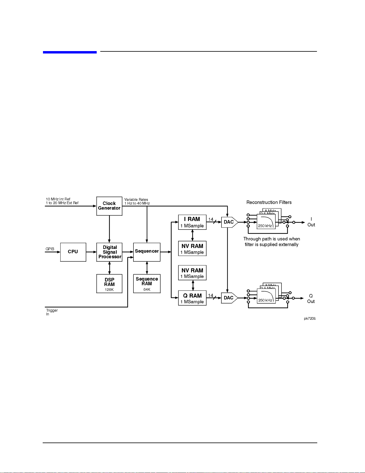
RF Modulation with Option UND. . . . . . . . . . . . . . . . . . . . . . . . . . . . . . . . . . . . . . . . . . . . . . .4-2
Clock Generator . . . . . . . . . . . . . . . . . . . . . . . . . . . . . . . . . . . . . . . . . . . . . . . . . . . . . . . . . . .4-2
Sequencer . . . . . . . . . . . . . . . . . . . . . . . . . . . . . . . . . . . . . . . . . . . . . . . . . . . . . . . . . . . . . . . .4-2
I RAM, Q RAM, and Nonvolatile RAM . . . . . . . . . . . . . . . . . . . . . . . . . . . . . . . . . . . . . . . . .4-2
ix
Page 10

Contents
Digital-to-Analog Converter and Filtering Hardware . . . . . . . . . . . . . . . . . . . . . . . . . . . . . 4-2
I/Q Modulator . . . . . . . . . . . . . . . . . . . . . . . . . . . . . . . . . . . . . . . . . . . . . . . . . . . . . . . . . . . . . 4-2
RF Hardware . . . . . . . . . . . . . . . . . . . . . . . . . . . . . . . . . . . . . . . . . . . . . . . . . . . . . . . . . . . . . 4-3
Managing Volatile and Non-Volatile ARB Memory. . . . . . . . . . . . . . . . . . . . . . . . . . . . . . . . . 4-4
Understanding Arbitrary Waveform Memory Types . . . . . . . . . . . . . . . . . . . . . . . . . . . . . . 4-4
Understanding Volatile ARB Waveform Memory. . . . . . . . . . . . . . . . . . . . . . . . . . . . . . . . . 4-5
Waveform Composition . . . . . . . . . . . . . . . . . . . . . . . . . . . . . . . . . . . . . . . . . . . . . . . . . . . . . . . 4-6
Event Markers and Sequencing . . . . . . . . . . . . . . . . . . . . . . . . . . . . . . . . . . . . . . . . . . . . . . 4-6
Waveform Limitations . . . . . . . . . . . . . . . . . . . . . . . . . . . . . . . . . . . . . . . . . . . . . . . . . . . . . .4-7
Understanding Arbitrary Waveform Generator Triggers . . . . . . . . . . . . . . . . . . . . . . . . . . . 4-8
Trigger Types . . . . . . . . . . . . . . . . . . . . . . . . . . . . . . . . . . . . . . . . . . . . . . . . . . . . . . . . . . . . . 4-8
Trigger Sources. . . . . . . . . . . . . . . . . . . . . . . . . . . . . . . . . . . . . . . . . . . . . . . . . . . . . . . . . . . . 4-9
Retrigger Mode. . . . . . . . . . . . . . . . . . . . . . . . . . . . . . . . . . . . . . . . . . . . . . . . . . . . . . . . . . . . 4-9
Understanding Baseband Clipping . . . . . . . . . . . . . . . . . . . . . . . . . . . . . . . . . . . . . . . . . . . . 4-10
How Power Peaks Develop. . . . . . . . . . . . . . . . . . . . . . . . . . . . . . . . . . . . . . . . . . . . . . . . . . 4-10
How Peaks Cause Spectral Regrowth . . . . . . . . . . . . . . . . . . . . . . . . . . . . . . . . . . . . . . . . . 4-12
How Clipping Reduces Peak-to-Average Power . . . . . . . . . . . . . . . . . . . . . . . . . . . . . . . . . 4-13
FIR Filtering Options (Option UN5 Only) . . . . . . . . . . . . . . . . . . . . . . . . . . . . . . . . . . . . . 4-15
5. Remote Programming
Bluetooth SCPI Command Reference . . . . . . . . . . . . . . . . . . . . . . . . . . . . . . . . . . . . . . . . . . . 5-2
Setting the Active Member Address . . . . . . . . . . . . . . . . . . . . . . . . . . . . . . . . . . . . . . . . . . . 5-2
Setting the Device Address . . . . . . . . . . . . . . . . . . . . . . . . . . . . . . . . . . . . . . . . . . . . . . . . . . 5-2
Burst Off On . . . . . . . . . . . . . . . . . . . . . . . . . . . . . . . . . . . . . . . . . . . . . . . . . . . . . . . . . . . . . . 5-2
Setting Clock/Gate Delay. . . . . . . . . . . . . . . . . . . . . . . . . . . . . . . . . . . . . . . . . . . . . . . . . . . . 5-2
Selecting the Payload Data . . . . . . . . . . . . . . . . . . . . . . . . . . . . . . . . . . . . . . . . . . . . . . . . . . 5-3
Setting Frequency Drift . . . . . . . . . . . . . . . . . . . . . . . . . . . . . . . . . . . . . . . . . . . . . . . . . . . . .5-3
Setting Frequency Offset . . . . . . . . . . . . . . . . . . . . . . . . . . . . . . . . . . . . . . . . . . . . . . . . . . . . 5-3
Setting the Modulation Index . . . . . . . . . . . . . . . . . . . . . . . . . . . . . . . . . . . . . . . . . . . . . . . . 5-4
Impairments. . . . . . . . . . . . . . . . . . . . . . . . . . . . . . . . . . . . . . . . . . . . . . . . . . . . . . . . . . . . . . 5-4
Selecting a Packet . . . . . . . . . . . . . . . . . . . . . . . . . . . . . . . . . . . . . . . . . . . . . . . . . . . . . . . . . 5-6
Setting the Burst Power Ramp . . . . . . . . . . . . . . . . . . . . . . . . . . . . . . . . . . . . . . . . . . . . . . . 5-6
Turning On Bluetooth . . . . . . . . . . . . . . . . . . . . . . . . . . . . . . . . . . . . . . . . . . . . . . . . . . . . . .5-6
CDMA Subsystem SCPI Command Reference (Options UND and UN5 Required) . . . . . . . 5-7
ARB Reference Internal External . . . . . . . . . . . . . . . . . . . . . . . . . . . . . . . . . . . . . . . . . . . . . 5-7
CDMA State . . . . . . . . . . . . . . . . . . . . . . . . . . . . . . . . . . . . . . . . . . . . . . . . . . . . . . . . . . . . . . 5-7
Channel Setup . . . . . . . . . . . . . . . . . . . . . . . . . . . . . . . . . . . . . . . . . . . . . . . . . . . . . . . . . . . . 5-8
Chip Rate . . . . . . . . . . . . . . . . . . . . . . . . . . . . . . . . . . . . . . . . . . . . . . . . . . . . . . . . . . . . . . . . 5-9
Clipping Level, |I+jQ|. . . . . . . . . . . . . . . . . . . . . . . . . . . . . . . . . . . . . . . . . . . . . . . . . . . . . 5-10
Clipping Level, |I|. . . . . . . . . . . . . . . . . . . . . . . . . . . . . . . . . . . . . . . . . . . . . . . . . . . . . . . . 5-10
Clipping Level, |Q| . . . . . . . . . . . . . . . . . . . . . . . . . . . . . . . . . . . . . . . . . . . . . . . . . . . . . . .5-10
Clipping, Pre/Post FIR Filter. . . . . . . . . . . . . . . . . . . . . . . . . . . . . . . . . . . . . . . . . . . . . . . . 5-10
Clipping, Type. . . . . . . . . . . . . . . . . . . . . . . . . . . . . . . . . . . . . . . . . . . . . . . . . . . . . . . . . . . . 5-10
Custom CDMA State, Store. . . . . . . . . . . . . . . . . . . . . . . . . . . . . . . . . . . . . . . . . . . . . . . . . 5-11
Custom Multicarrier, Store . . . . . . . . . . . . . . . . . . . . . . . . . . . . . . . . . . . . . . . . . . . . . . . . . 5-11
External Delay State . . . . . . . . . . . . . . . . . . . . . . . . . . . . . . . . . . . . . . . . . . . . . . . . . . . . . .5-12
External Delay Time . . . . . . . . . . . . . . . . . . . . . . . . . . . . . . . . . . . . . . . . . . . . . . . . . . . . . . 5-12
External Polarity . . . . . . . . . . . . . . . . . . . . . . . . . . . . . . . . . . . . . . . . . . . . . . . . . . . . . . . . . 5 -1 2
Filter Alpha, Nyquist, or Root Nyquist. . . . . . . . . . . . . . . . . . . . . . . . . . . . . . . . . . . . . . . . 5-12
x
Page 11

Contents
Filter BbT, Gaussian. . . . . . . . . . . . . . . . . . . . . . . . . . . . . . . . . . . . . . . . . . . . . . . . . . . . . . .5-13
Filter Selection . . . . . . . . . . . . . . . . . . . . . . . . . . . . . . . . . . . . . . . . . . . . . . . . . . . . . . . . . . .5-13
Filter Optimization . . . . . . . . . . . . . . . . . . . . . . . . . . . . . . . . . . . . . . . . . . . . . . . . . . . . . . . .5-14
Gate Active . . . . . . . . . . . . . . . . . . . . . . . . . . . . . . . . . . . . . . . . . . . . . . . . . . . . . . . . . . . . . .5-14
Multicarrier Define . . . . . . . . . . . . . . . . . . . . . . . . . . . . . . . . . . . . . . . . . . . . . . . . . . . . . . . .5 -14
Multicarrier Setup Select . . . . . . . . . . . . . . . . . . . . . . . . . . . . . . . . . . . . . . . . . . . . . . . . . . .5-15
Oversample Ratio . . . . . . . . . . . . . . . . . . . . . . . . . . . . . . . . . . . . . . . . . . . . . . . . . . . . . . . . .5 -1 5
Reconstruction Filter . . . . . . . . . . . . . . . . . . . . . . . . . . . . . . . . . . . . . . . . . . . . . . . . . . . . . .5-15
Reference Frequency. . . . . . . . . . . . . . . . . . . . . . . . . . . . . . . . . . . . . . . . . . . . . . . . . . . . . . .5-16
Retrigger Mode State . . . . . . . . . . . . . . . . . . . . . . . . . . . . . . . . . . . . . . . . . . . . . . . . . . . . . .5-16
Setup Select. . . . . . . . . . . . . . . . . . . . . . . . . . . . . . . . . . . . . . . . . . . . . . . . . . . . . . . . . . . . . .5-16
Trigger Source. . . . . . . . . . . . . . . . . . . . . . . . . . . . . . . . . . . . . . . . . . . . . . . . . . . . . . . . . . . .5-17
Trigger Type . . . . . . . . . . . . . . . . . . . . . . . . . . . . . . . . . . . . . . . . . . . . . . . . . . . . . . . . . . . . .5-17
User FIR Definition . . . . . . . . . . . . . . . . . . . . . . . . . . . . . . . . . . . . . . . . . . . . . . . . . . . . . . .5-17
Waveform Length . . . . . . . . . . . . . . . . . . . . . . . . . . . . . . . . . . . . . . . . . . . . . . . . . . . . . . . . .5-17
Digital Modulation Subsystem SCPI Command Reference. . . . . . . . . . . . . . . . . . . . . . . . . .5-18
Define User FIR . . . . . . . . . . . . . . . . . . . . . . . . . . . . . . . . . . . . . . . . . . . . . . . . . . . . . . . . . .5-18
Digital Modulation Setup . . . . . . . . . . . . . . . . . . . . . . . . . . . . . . . . . . . . . . . . . . . . . . . . . . .5-18
Digital Modulation State . . . . . . . . . . . . . . . . . . . . . . . . . . . . . . . . . . . . . . . . . . . . . . . . . . .5-18
External Delay State. . . . . . . . . . . . . . . . . . . . . . . . . . . . . . . . . . . . . . . . . . . . . . . . . . . . . . .5-19
External Delay Time. . . . . . . . . . . . . . . . . . . . . . . . . . . . . . . . . . . . . . . . . . . . . . . . . . . . . . .5-19
External Polarity. . . . . . . . . . . . . . . . . . . . . . . . . . . . . . . . . . . . . . . . . . . . . . . . . . . . . . . . . .5-19
Filter Alpha, Nyquist, or Root Nyquist . . . . . . . . . . . . . . . . . . . . . . . . . . . . . . . . . . . . . . . .5-19
Filter BbT, Gaussian. . . . . . . . . . . . . . . . . . . . . . . . . . . . . . . . . . . . . . . . . . . . . . . . . . . . . . .5-20
Filter Optimization . . . . . . . . . . . . . . . . . . . . . . . . . . . . . . . . . . . . . . . . . . . . . . . . . . . . . . . .5-20
Filter Selection . . . . . . . . . . . . . . . . . . . . . . . . . . . . . . . . . . . . . . . . . . . . . . . . . . . . . . . . . . .5-20
FSK Frequency Deviation. . . . . . . . . . . . . . . . . . . . . . . . . . . . . . . . . . . . . . . . . . . . . . . . . . .5-21
Gate Active Polarity . . . . . . . . . . . . . . . . . . . . . . . . . . . . . . . . . . . . . . . . . . . . . . . . . . . . . . .5-21
Modulation Type . . . . . . . . . . . . . . . . . . . . . . . . . . . . . . . . . . . . . . . . . . . . . . . . . . . . . . . . . .5-21
Multicarrier Phase . . . . . . . . . . . . . . . . . . . . . . . . . . . . . . . . . . . . . . . . . . . . . . . . . . . . . . . .5-22
Multicarrier Setup . . . . . . . . . . . . . . . . . . . . . . . . . . . . . . . . . . . . . . . . . . . . . . . . . . . . . . . .5-23
Multicarrier Setup: Number of Carriers . . . . . . . . . . . . . . . . . . . . . . . . . . . . . . . . . . . . . . .5-23
Multicarrier Setup: Loading User File . . . . . . . . . . . . . . . . . . . . . . . . . . . . . . . . . . . . . . . .5-23
Multicarrier Table Setup . . . . . . . . . . . . . . . . . . . . . . . . . . . . . . . . . . . . . . . . . . . . . . . . . . .5-24
Retrigger Mode State . . . . . . . . . . . . . . . . . . . . . . . . . . . . . . . . . . . . . . . . . . . . . . . . . . . . . .5-24
Store Custom Modulation File . . . . . . . . . . . . . . . . . . . . . . . . . . . . . . . . . . . . . . . . . . . . . . .5-24
Store Multicarrier File . . . . . . . . . . . . . . . . . . . . . . . . . . . . . . . . . . . . . . . . . . . . . . . . . . . . .5-25
Symbol Rate. . . . . . . . . . . . . . . . . . . . . . . . . . . . . . . . . . . . . . . . . . . . . . . . . . . . . . . . . . . . . .5-25
Trigger Source. . . . . . . . . . . . . . . . . . . . . . . . . . . . . . . . . . . . . . . . . . . . . . . . . . . . . . . . . . . .5-25
Trigger Type . . . . . . . . . . . . . . . . . . . . . . . . . . . . . . . . . . . . . . . . . . . . . . . . . . . . . . . . . . . . .5-25
Dual ARB Subsystem SCPI Command Reference (Option UND Only) . . . . . . . . . . . . . . . .5-26
ARB State . . . . . . . . . . . . . . . . . . . . . . . . . . . . . . . . . . . . . . . . . . . . . . . . . . . . . . . . . . . . . . .5-26
ARB Reference Internal External . . . . . . . . . . . . . . . . . . . . . . . . . . . . . . . . . . . . . . . . . . . .5-26
Clipping . . . . . . . . . . . . . . . . . . . . . . . . . . . . . . . . . . . . . . . . . . . . . . . . . . . . . . . . . . . . . . . . .5-26
Create Waveform Sequence . . . . . . . . . . . . . . . . . . . . . . . . . . . . . . . . . . . . . . . . . . . . . . . . .5-27
External Delay State. . . . . . . . . . . . . . . . . . . . . . . . . . . . . . . . . . . . . . . . . . . . . . . . . . . . . . .5-27
External Delay Time. . . . . . . . . . . . . . . . . . . . . . . . . . . . . . . . . . . . . . . . . . . . . . . . . . . . . . .5-27
External Polarity. . . . . . . . . . . . . . . . . . . . . . . . . . . . . . . . . . . . . . . . . . . . . . . . . . . . . . . . . .5-27
Gate Active . . . . . . . . . . . . . . . . . . . . . . . . . . . . . . . . . . . . . . . . . . . . . . . . . . . . . . . . . . . . . .5-28
xi
Page 12

Contents
Markers. . . . . . . . . . . . . . . . . . . . . . . . . . . . . . . . . . . . . . . . . . . . . . . . . . . . . . . . . . . . . . . . . 5-28
Reconstruction Filter . . . . . . . . . . . . . . . . . . . . . . . . . . . . . . . . . . . . . . . . . . . . . . . . . . . . . .5-30
Reference Frequency . . . . . . . . . . . . . . . . . . . . . . . . . . . . . . . . . . . . . . . . . . . . . . . . . . . . . . 5-30
Retrigger Mode State . . . . . . . . . . . . . . . . . . . . . . . . . . . . . . . . . . . . . . . . . . . . . . . . . . . . . . 5-31
Sample Clock . . . . . . . . . . . . . . . . . . . . . . . . . . . . . . . . . . . . . . . . . . . . . . . . . . . . . . . . . . . . 5-31
Scaling. . . . . . . . . . . . . . . . . . . . . . . . . . . . . . . . . . . . . . . . . . . . . . . . . . . . . . . . . . . . . . . . . . 5-31
Select Waveform. . . . . . . . . . . . . . . . . . . . . . . . . . . . . . . . . . . . . . . . . . . . . . . . . . . . . . . . . . 5-31
Trigger Source . . . . . . . . . . . . . . . . . . . . . . . . . . . . . . . . . . . . . . . . . . . . . . . . . . . . . . . . . . . 5-31
Trigger Type . . . . . . . . . . . . . . . . . . . . . . . . . . . . . . . . . . . . . . . . . . . . . . . . . . . . . . . . . . . . . 5-32
Multitone Waveforms . . . . . . . . . . . . . . . . . . . . . . . . . . . . . . . . . . . . . . . . . . . . . . . . . . . . . . .5-33
Creating a Multitone Waveform . . . . . . . . . . . . . . . . . . . . . . . . . . . . . . . . . . . . . . . . . . . . . 5-33
Turning a Multitone Waveform On and Off . . . . . . . . . . . . . . . . . . . . . . . . . . . . . . . . . . . . 5-35
Storing a Multitone Waveform . . . . . . . . . . . . . . . . . . . . . . . . . . . . . . . . . . . . . . . . . . . . . . 5-35
Retrieving a Stored Multitone Waveform . . . . . . . . . . . . . . . . . . . . . . . . . . . . . . . . . . . . . . 5-35
6. Programming Command Cross-Reference
AWGN Softkeys. . . . . . . . . . . . . . . . . . . . . . . . . . . . . . . . . . . . . . . . . . . . . . . . . . . . . . . . . . . . . 6-2
Bluetooth Softkeys. . . . . . . . . . . . . . . . . . . . . . . . . . . . . . . . . . . . . . . . . . . . . . . . . . . . . . . . . . . 6-3
CDMA Formats > IS-95A Softkeys. . . . . . . . . . . . . . . . . . . . . . . . . . . . . . . . . . . . . . . . . . . . . . 6-5
Dual ARB Softkeys . . . . . . . . . . . . . . . . . . . . . . . . . . . . . . . . . . . . . . . . . . . . . . . . . . . . . . . . . 6-10
Multitone Softkeys. . . . . . . . . . . . . . . . . . . . . . . . . . . . . . . . . . . . . . . . . . . . . . . . . . . . . . . . . . 6-14
Other Formats Softkeys . . . . . . . . . . . . . . . . . . . . . . . . . . . . . . . . . . . . . . . . . . . . . . . . . . . . .6-15
xii
Page 13

ESG Family Signal Generators
Options UND & UN5
1The Dual Arbitrary Waveform Generator
This guide provides information specific to the Dual Arbitrary Waveform Generator
(Option UND), and the multichannel, multicarrier CDMA personality (Option UN5)
available with this option. Option UND can be used alone, but Option UN5 requires the
installat i on of O ption UND.
Dual Arbitrary Waveform Generator User’s and Programming Guide 1-1
Page 14
The Dual Arbitrary Waveform Generator ESG Family Signal Generators
Overviews Options UND & UN5
Overviews
This section contains the following overviews:
• “Dual Arbitrary Waveform Generator (Option UND)”
• “Multichannel, Multicarrier CDMA Personality (Option UN5)” on page 1-4
Specifications
Option specifications are included in the technical specifications document.
Dual Arbitrary Waveform Generator (Option UND)
Option UND enables you to drive the signal generator’s internal I/Q modulator to create
vector-modulated signals. The Dual Arbitrary Waveform Generator uses 14-bit DACs for
superior fidelity, as well as sampl e rates ranging from 1 Hz to 40 MHz, and 1 Megasample
memory per channel.
The Dual Arbitrary Waveform Generator has a digital signal proces sor capable of
simulating optional digital communication formats, such as the “Multichannel,
Multicarrier CDMA Personality (Option UN5)” described on page 1-4.
Alternately, you can use an external simulation (such as Omnisys) to generate the I/Q
waveforms , do wnload them into th e I RAM and Q RAM, and s equence them for “pla yback. ”
Using simple table editors, you can save different waveforms as se parate segments, and
subsequently sequence them to create a chain of repeating w aveform types. You can store
this information to the signal generator’s internal memory and recall it as needed.
1-2
Dual Arbitrary Waveform Generator User’s and Programming Guide
Page 15

ESG Family Signal Generators The Dual Arbitrary Waveform Generator
Options UND & UN5 Overviews
Option UND also includes the following:
• Waveform triggering. Trigger types include continuous, single, gated, and (while using
waveform sequence s) segme nt advance. The retrigger mode is ad justable , as well as the
gate active trigger polarity for gated triggers. The trigger source can be set to the signal
generator’s front panel trigger hardkey, the GPIB interface, or an external trigger
signal supplied to the rear panel P ATTERN TRIG IN connector. External triggers
include adjustable polarity, delay, and delay time.
• Waveform utilities:
❏ Markers, the signal generator has two markers, that you can place on a waveform
segment. Markers provide auxiliary output signals that are synchronized with a
waveform segment. You can construct these output signals as a trigger signal to
synchronize another instrument to a given portion of a waveform.
❏ Scaling to change the peak-to-peak output value of a wave form segment to a desired
percentage of its full-scale value.
❏ Baseband clipping to limit peaks in a waveform segment by clipping the envelope to
a desired percentage of the highest peak. You can clip the composite I/Q waveform or
Iand Q separately.
• Additive White Gaussian Noise. AWGN can be used to crea te nois e signals with
adjustable bandwidth, waveform length and noise seed (fixed or random).
• Multitone wa veforms. You can generate multitone wavefor ms with adjustable frequency
spacing, frequency offset, power, phase, and tone on/off state.
• The Bluetooth wavef orm. You can generate packets (DH1) and impairments (ad justable
frequency offset, frequency drift, modulation index, and AWGN).
• Other Formats. You can generate single carrier or multicarrier waveforms consisting of
preconfigured or custom digital modulation formats:
❏ Triggering types include, s ingle, c ontinuous , or gated w aveform trigger ing , inc luding
retrigger mo de.
❏ Multicarrier wavefo rms with an adjust able number of car riers, frequency offset, and
power.
❏ Custom single carrier waveforms with configurable digital modulation type, filter,
and symbol rate.
Dual Arbitrary Waveform Generator User’s and Programming Guide 1-3
Page 16

The Dual Arbitrary Waveform Generator ESG Family Signal Generators
Overviews Options UND & UN5
Multichannel, Multicarrier CDMA Personality (Option UN5)
Option UN5 provides multichannel, multicarrier IS-95 CDMA personality for amplifier
characterization. This option requires Option UND.
Multichannel CDMA signal generation is simplified by the inclusion of 9-, 32-, and
64-channel pre-defined waveforms, offering precise signal statistics while optimizing
measurement accuracy.
Multicarrier CDMA signal generation is simplified by the inclusion of 3- and 4-carrier
pre-defined waveforms, offering precise signal statistics while optimi zi ng measurement
accuracy.
Mobile component test is simplified using pre-defined Pilot and Reverse channel signals,
and the ability to generate multiple pilot channels (Walsh 0, different PN offset) at equal
or differing power levels. You can also generate a single reverse channel for mobile
amplifier testing.
Option UN5 also allows for custom, user-defined multichannel and multicarrier CDMA
signals. The multichannel capab ilities include the simulation of fully loaded cells by
generating up to 256 Walsh-coded channels, as well as the ability to define power, PN
offset, and data for each Walsh-coded channel. Multicarrier capabilities include the ability
to generate multicarrier CDMA setups employing up to twelve carriers with individually
defined multichannel configurations, frequency offsets, and power levels. Option UN5 also
includes the ability to download or enter user-defined FIR filter coefficients.
Waveform triggering is included with Option UN5. Trigger types include continuous,
single, and gated. The retrigger mode is adjustable, as well as the gate active trigger
polarity for g a t ed tr i g g e rs. The tr i g ge r source can be se t to th e si g n a l ge n e ra t o r’s fron t
panel trigger hardkey, the GPIB interface, or an external trigg er signal supplied to the
rear panel PATTERN TRIG IN connector. External triggers include adjustable polarity,
delay, and delay time.
The baseband clipping capability allows you to clip the composite I/Q w aveform or I and Q
separately. You can also choose either pre- or post-FIR filter clipping.
1-4
Dual Arbitrary Waveform Generator User’s and Programming Guide
Page 17

ESG Family Signal Generators
Options UND & UN5
2Using Functions
This chapter contains procedures that show you how to use some of the major functions of
the dual arbitrary waveform generator (Option UND) and the multichannel, multicarrier
CDMA personality (Option UN5).
Dual Arbitrary Waveform Generator User’s and Programming Guide 2-1
Page 18

Using Functions ESG Family Signal Generators
Table Editor Basics Options UND & UN5
Table Editor Ba si cs
Option UND provides several table editors that enable you to:
• edit a CDMA channel setup (for details, see page 2-4)
• edit a multicarrier CDMA setup (for details, see page 2-15)
• create a user-defined FIR filter (for details, see page 2-35)
• create multitone waveforms (for details, see page 2-47)
• build and edit waveform sequences (for details, see page 2-54)
• edit waveform segments (for details, see page 2-55)
While each of these table editors performs a different function, they are all used in
basically the same way, and most of the table editors have several editing softkeys in
common.
Common Edit Functions
Edit Item Enables you to use the front panel knob and arrow keys to edit the value of
a selected entry. After highlighting the value you want to edit, press this
softkey.
Insert Row Inserts a row for data above the currently selected row.
Delete Row Deletes the currently selected row of data.
Goto Row Displays a new page of softkeys so that you can quickly move to the
first, middle, or last row of data. This is especially helpful in a large
table, or when using the filter table editor mirror function.
Restore Default
Filter
Enables you to reset factory default values for a filter.
Load/Store
or Load Store Displays a new page of softkeys that enables you t o load data from a store d
file save data to a file, or delete a stored fi le.
Delete All Rows Clears all data from a table.
CAUTION There is no “undo” command. Once you delete data from a table, you cannot
retrieve it.
2-2
Dual Arbitrary Waveform Generator User’s and Programming Guide
Page 19

ESG Family Signal Generators Using Functions
Options UND & UN5 Creating Custom CDMA States
Creating Custom CDMA States
Using this procedure, you will create a custom, forward 33 channel CDMA signal at IS-97
power levels with a traffic channel carrying user-defined data at a Walsh code of 45.
The signal generator provides a quick and easy solution to cre ating custom CDMA states.
Rather than building the entire 33 channel set up from scratch, you will start with a
forward 32 channel CDMA template and modify the template by adding one channel and
changing some of the template’s default values. (Options UND and UN5 are both
required.)
Setting up a CDMA Template
The first step in creating a customized CDMA state is setting up a template that can be
modified to fill your requirements. Follow these steps to set up a forward 32 channel
CDMA template:
1. Preset the signal generator to normal preset conditions.
2. Press the front panel
Mode key.
3. If you have multiple options and the
next.
4. Press
Press
CDMA Formats > IS-95A > Setup Select. The default CDMA template is set to 9 Ch Fwd.
32 Ch Fwd. This sets up a template containing 32 forward CDMA channels.
Arb Waveform Generator softkey is visible, press it
Dual Arbitrary Waveform Generator User’s and Programming Guide 2-3
Page 20

Using Functions ESG Family Signal Generators
Creating Custom CDMA States Options UND & UN5
Modifying a CDMA Template
Follow these steps to modify the standard forward 32 channel CDMA template that was
loaded in the previous steps. You will be inserting a traffic channel, modifying the new
channel’s Walsh code to 45, changing the random data to user-defined data, and adjusting
the overall code domain power to IS-97 levels.
1. Press
CDMA Define > Edit Channel Setup. This opens the table editor used to modify a
CDMA channel setup. The follo wing figure shows the 32 channel CDMA templ ate in the
CDMA Channel Setup table editor.
2. As shown in the previous figure, row 8 is a Traffic channel. Select row 8 by pressing the
front panel down arrow key until Traffic is highlighted. You are now ready to insert a
new Traffic channel on table row 8.
2-4
Dual Arbitrary Waveform Generator User’s and Programming Guide
Page 21

ESG Family Signal Generators Using Functions
Options UND & UN5 Creating Custom CDMA States
Adding a New Channel Type
1. Press Insert Row. You are now offered the choice between Pilot, Sync, Paging,and Traffic
channels.
2. Press
38, at a power level of
Traffic. You now have a new traffic channel inserted on table row 8, at Walsh cod e
−15.95 dB with a 0 PN offset, transmitting random data. The
channel that formally occupied table row 8 has moved (along with the cursor) to ta ble
row 9 (and the channel formerly occupying table row 9 has moved to table row 10, and
so on, down to table row 33). The total number of channels is now 33. Your display will
look like this:
3. Press the
Return hardkey.
Modifying the Walsh Code
1. Use the front panel knob or the arrow keys to highlight the Walsh code value (38) on
table row 8.
2. Press
3. Using the numeric keypad, press
Edit Item. Walsh Code: 38 appears in the active entry area of the displa y.
45 and termin a te th e en try with the Enter softkey . The
Walsh code for the channel on table row 8 has now been set to 45.
Modifying the Data
1. Use the front panel knob or arrow keys t o highlight the Data value ( RANDOM) on table
row 8.
2. Press
3. Using the front panel knob, the up- and down-arrow keys, or the numeric keypad enter
00001000 and press the Enter softkey to terminate the entry. The data value on table row
8 has now been changed from
Edit Item. Data: RANDOM appears in the active entry area of the displa y.
RANDOM to 00001000.
Dual Arbitrary Waveform Generator User’s and Programming Guide 2-5
Page 22

Using Functions ESG Family Signal Generators
Creating Custom CDMA States Options UND & UN5
Modifying the Code Domain Power
You will now adjust the overall code domain power of the custom CDMA state’s c hannels to
conform to IS-97 levels.
1. Press
2. Press
Adjust Code Domain Power.
IS-97 Levels. The signal generator’s firmware calculates the power levels of all
33 channels and adjusts them to conform to IS-97 power levels, as shown in the figure
below.
You now have a custom, forward 33 channel CDMA signal at IS-97 power levels, with a
traffic channel carrying user-defined data at a Walsh code of 45 on table row 8. The next
section provides instructions about how to apply the modified channel setup and activate
the new CDMA state.
2-6
Dual Arbitrary Waveform Generator User’s and Programming Guide
Page 23

ESG Family Signal Generators Using Functions
Options UND & UN5 Creating Custom CDMA States
Applying a Custom Channel Setup, then Activating the
Custom CDMA State and Applying it to the RF Output
This example uses the custom, forward 33 channel CDMA state created in “Creating
Custom CDMA States” on page 2-3. (Options UND and UN5 are both required.)
1. Press the
Return hardkey to ret u rn to the previous me n u, then press Apply Channel Setup
to update the waveform to the CDMA state created in the previous steps. The display
changes to
2. Press
CDMA Setup: 32 Ch Fwd (Modified). Press Return.
CDMA Off On until On is highlighted. Note that the CDMA and I/Q annunciators turn
on. After waveform generation, the new waveform is stored in volatile memory, and is
ready for application to the RF output.
3. Set the signal generator’s RF output frequency to 890.01 MHz, and the RF output
power to −10 dBm. If Mod On/Off is off, turn it on (the
MOD ON annunciator appears on
the display).
4. To activate the RF output, press
RF On/Off to On. The RF ON annunciator appears on the
signal generator’s display. See the following figure.
Dual Arbitrary Waveform Generator User’s and Programming Guide 2-7
Page 24

Using Functions ESG Family Signal Generators
Creating Custom CDMA States Options UND & UN5
Clipping a CDMA Waveform
This example uses the custom, forward 33 channel CDMA state created in “Creating
Custom CDMA States” on page 2-3. (Options UND and UN5 are both required.)
After you turn on and apply a CDMA state (see the previous section), use the following
procedure to configure and apply clipping to the CDMA waveform.
1. Notice that in the status area of the display the current clipping setup is
PRE Clip |I+jQ|: 100.0%. A clipping level of 100 percent is equal to no clipping.
2. Press
3. Notice that the
selection clips the combined I and Q waveform. Alternatively,
CDMA Define > More (1 of 2) > Clipping to access the clipping setup menu.
Clipping Type |I+jQ| |I|,|Q| softkey default is |I+jQ| (circular clipping). This
|I|,|Q| (rectangular
clipping) clips the I and Q waveforms separately. Use the default selection for this
example.
4. Press
5. Notice that the
waveform is cli pped prior to FIR filtering. Alternatively, when you select
Clip |I+jQ| To and enter 80 percent.
Clip At PRE POST FIR Filter softkey default is PRE. With PRE selected, the
POST, the
waveform is clipped after FIR filtering. Use the default selection for this example.
6. Press
Apply to Waveform. The signal generator rebuild s the waveform and th e clipping
settings are updated in the status area of the displa y, as shown. For more information
on clipping, refer to “Understanding Baseband Clipping” on page 4-10.
2-8
Dual Arbitrary Waveform Generator User’s and Programming Guide
Page 25

ESG Family Signal Generators Using Functions
Options UND & UN5 Creating Custom CDMA States
Viewing Code Domain Power and Waveform Statistics
The signal generator can display a graphical rep res entation of code domain power and
Complementary Cumulative Distribution Function. To view this representation, press
Mode > ARB Waveform Generator (if it appears) > CDMA Formats > IS-95A > CDMA Define >
Edit Channel Setup > Display Code Domain Power. The following figure depicts your customized
CDMA waveform’s code domain power.
Code domain power is displayed as a graph depicting power (in decibels) on the y-axis and
Walsh Code on the x-axis. PN offset is also displayed along with total code domain power.
If there is channel data assigned to more than one PN offset, pressi ng the
Domain Power
Offset.
softkey will open a menu where you can select Previous PN Offset or Next PN
Display Code
The following is an example of the Code Domain Power graph display with the additional
softkeys.
Dual Arbitrary Waveform Generator User’s and Programming Guide 2-9
Page 26

Using Functions ESG Family Signal Generators
Creating Custom CDMA States Options UND & UN5
After viewing the code domain power, press Return 3 times to return to the top-level CDMA
menu where
CDMA Off On is the first softkey.
Complementary Cumulative Distribution Function is a representa tion of the probable
occurrence of power peaks compared to average power. To view the Complementary
Cumulative Distribution Function for your CDMA waveform, press
Plot CCDF. The following figure depicts the Complementary Cumulative Distribution
Waveform Statistics >
function for your CDMA waveform.
2-10
Dual Arbitrary Waveform Generator User’s and Programming Guide
Page 27

ESG Family Signal Generators Using Functions
Options UND & UN5 Storing a Custom CDMA State to Memory
Storing a Custom CDMA State to Memory
Using this procedure, you will learn how to store a custom CDMA state to the signal
generator’s memory catalog. For this example, use the custom, forward 33 channel CDMA
state you created in the previous procedure. If you have not created this custom CDMA
state, refer to the previous section, “Creating Custom CDMA States.” (Options UND and
UN5 are both required.)
1. In the top-level CDMA menu, press
2. Press
Store Custom CDMA State. This softkey displays the signal generator’s catalog of
CDMA files.
3. Press
Store To File to open a menu of letters and symbols that you can use to name the
file.
CDMA Define.
Dual Arbitrary Waveform Generator User’s and Programming Guide 2-11
Page 28

Using Functions ESG Family Signal Generators
Storing a Custom CDMA State to Memory Options UND & UN5
4. Name this file 33CHFWD97 (33 channel forward at IS-97 levels). If ther e is already a file
highlighted in the CDMA catalog, press
C > HIJKLM > H > ABCDEF > F > VWXYZ_$ > W > ABCDEFG > D > 9 > 7 and terminate the
entry by pressing
Enter. You now have a file called 33CHFWD97 store d i n th e si g n a l
Edit Keys > Clear Text. Press: 3 > 3 > ABCDEFG >
generator’s volatile ARB memory, as shown in the following figure.
2-12
Dual Arbitrary Waveform Generator User’s and Programming Guide
Page 29

ESG Family Signal Generators Using Functions
Options UND & UN5 Recalling Custom CDMA States
Recalling Custom CDMA States
Using this procedure, you will recall a custom CDMA state from the signal generator’s
memory. For this example, use the custom, forward 33 channe l CDMA state created in the
procedure titled, “Creating Custom CDMA States” and stored using the procedure
titled, “Storing Custom CDMA States.” If you have not created and stored a cus tom CDMA
state, refer to these previous sections. (Options UND and UN5 are both required.)
1. Preset the signal generator to normal preset conditions.
2. Press the front panel
Mode key.
3. If you have multiple options and the
next.
4. Press
Press
CDMA Formats > IS-95A > Setup Select. The default CD MA template is s e t to 9 Ch Fwd.
Custom CDMA State. This opens a catalog of custom CDMA states, as shown in the
following figure.
Arb Waveform Generator softkey is visible, press it
5. Use the front panel knob or the arrow keys to highlight the file
Select File. The custom CDMA state 33CHFWD97 is selected.
Dual Arbitrary Waveform Generator User’s and Programming Guide 2-13
33CHFWD97, then press
Page 30

Using Functions ESG Family Signal Generators
Recalling Custom CDMA States Options UND & UN5
6. To activate the recalled custom CDMA state, press CDMA Off On to On. The firmware
generates the custom CDMA waveform in ARB memory. After waveform
generation, the custom CDMA state is available to be modulated on the RF output. See
the following figu r e.
7. At signal generator preset,
presetting the signal generator, press
Mod On/Off is set to On. If you did not start this procedure by
Mod On/Off to On.
NOTE The RF output amplitude and frequency settings are not saved as part of a
custom CDMA state file. At signal generator preset (or line power cycle), the
RF output frequency is reset to the signal generator’s highest specified value
and the RF output amplitude is reset to
−135 dBm. Before activating the RF
output, make adjustments to the RF output frequency and amplitude as
required.
8. To activate the RF output, press
RF On/Off to On.
2-14
Dual Arbitrary Waveform Generator User’s and Programming Guide
Page 31

ESG Family Signal Generators Using Functions
Options UND & UN5 Creating Custom Multicarrier CDMA Waveforms
Creating Custom Multicarrier CDMA Waveforms
Using this procedure, you will create a custom 5-carrier CDMA waveform.
The signal generator provides a quick and easy solution to creating custom multicarrier
CDMA waveforms. Rather than building the entire 5-carrier setup from scratch, you will
start with a 3-carrier CDMA template and modify the template by adding two additio nal
carriers and changing some of the template’s default values. (Options UND and UN5 are
both required.)
Opening the Multicarrier CDMA Setup Table Editor
1. Preset the signal generator.
Press
Preset to return the signal generator to normal preset conditions.
2. Activate the multicarrier CDMA mode.
Press the front panel
Generator softkey is visible, press it next.) Press CDMA Formats > IS-95A > Multicarrier Off On
until
On is highlighted.
Mode key. (If you have multiple options and the Arb Waveform
3. Open the Multicarrier CDMA Setup table editor.
Press
Multicarrier Define. This opens the Multicarrier CDMA Setup table editor. The
3-carrier CDMA template is automatically placed in the table editor when the table
editor is opened.
Dual Arbitrary Waveform Generator User’s and Programming Guide 2-15
Page 32

Using Functions ESG Family Signal Generators
A
Creating Custom Multicarrier CDMA Waveforms Options UND & UN5
Understanding the Multicarrier CDMA Setup Table Editor
You can use the Multicarrier CDMA Setup table editor to create multicarrier CDMA
waveforms containing up to 12 carr iers. Along with the arrow keys and the front panel
knob, the Multicarrier CDMA Setup softkeys are used to move throughout the table
entries, edit the values, insert/delete table rows, and to apply and store the custom
multicarrier CDMA setup.
The following values are definable for each individual carrier:
• Carrier Type - pilot, 9 channel forward, 32 channel forward, 64 channel
forward, re v e rse, or custom C D MA carriers
• Frequency Offset - adjustable from
• Power Level - adjus table from
ctive Entry Area
−40.0 to 0.00 dB
−7.5 to 7.5 MHz
Multicarrier CDMA
Setup softkeys
Carrier Type
2-16
Frequency Offset Value Power Value
Dual Arbitrary Waveform Generator User’s and Programming Guide
Page 33

ESG Family Signal Generators Using Functions
Options UND & UN5 Creating Custom Multicarrier CDMA Waveforms
Modifying a Multicarrier CDMA 3-Ca rr ier Template
Use the following steps to modify the standard 3-carrier CDMA template that was loaded
in the previous steps. You will be inserting one pilot carrier and another 32 channel
forward carrier, and modifying the frequency offset and power values for both new car riers .
1. Add the first new carrier.
Using the front panel knob or the arrow keys, move the cursor until the second
9 channel forward carrier (in table row 2) is highlighted. Press:
inserts a pilot carrier be tween the firs t two 9 channel forward c arriers . Press
new pilot carrier has a default frequency offset of 0.0 00 kHz and a default power level of
0.00 dB, as shown in the following figure.
Insert Row > Pilot. This
Return. The
New Pilot Carrier Frequency Offset 0.000 MHz Power 0.000 dB
Dual Arbitrary Waveform Generator User’s and Programming Guide 2-17
Page 34

Using Functions ESG Family Signal Generators
Creating Custom Multicarrier CDMA Waveforms Options UND & UN5
2. Modify the frequency offset value.
Highlight the new pilot carrier’s frequency offset value and press
the numeric keypad, enter
−625 and press the kHz terminator. Note that after you enter
Edit Item. Then, using
the new frequency offset value, the cursor moves downward in the same column, r eady
to modify the next entry in the same category, as shown in the following figure.
Frequency Offset -625.000 kHz
3. Modify the power level.
Highlight the pilot carrier’s power value and press
the
dB terminator. The following figure shows the modified power value.
Edit Item. Then enter −10 and press
Power -10.00 dB
2-18
Dual Arbitrary Waveform Generator User’s and Programming Guide
Page 35

ESG Family Signal Generators Using Functions
Options UND & UN5 Creating Custom Multicarrier CDMA Waveforms
4. Add the second new carrier.
Move the cursor until the third 9 channel forward carrier (table row 4) is highlighted.
Press
second and third 9 channel forward carriers. Press
Insert Ro w > 32 Ch Fwd. This inserts a 32 channel forward carrier between the
Return. The new 32 channel forward
carrier has a default frequency offset of 1.250000 MHz and a default power level of
0.00 dB, as shown in the following figure.
New 32 Ch Fwd Carrier Type
Frequency Offset 1.250000 MHz Power 0.000 dB
5. Modify the frequency offset.
Highlight the new 32 channel forward carrier’s frequency offset value and press
Edit Item. Then enter 625 and press the kHz terminator.
Frequency Offset 625.000 kHz
Dual Arbitrary Waveform Generator User’s and Programming Guide 2-19
Page 36

Using Functions ESG Family Signal Generators
Creating Custom Multicarrier CDMA Waveforms Options UND & UN5
6. Modify the power level.
Highlight the new 32 channel forward carrier’s power value and press
enter
−5 and press the dB terminator.
Power -5.00 dB
Edit Item. Then
2-20
Dual Arbitrary Waveform Generator User’s and Programming Guide
Page 37

ESG Family Signal Generators Using Functions
Options UND & UN5 Creating Custom Multicarrier CDMA Waveforms
Applying and Activating the Custom Multicarrier CDMA Setup
You now have a custom 5-carrier CDMA signal. Follow the in struct ions below to app ly and
activate the custom multicarrier C DMA setup.
1. Apply the new custom multicarrier CDMA setup.
Press
Off On
CDMA setup while CDMA is activated.) This updates the waveform to the custom
multicarrier CDMA state you created and modified during the previous steps. Press
Return. Notice that the display shows that the Multicarrier Setup has been changed
from
Carriers (Modified)
2. Activate the new custom multicarrier CDMA setup.
Apply Multicarrier. (Note that i t is not ne cessa ry to apply t he new setup unless CDMA
is set to On. Apply Multicarrier is used to apply changes made to the multicarrier
Multicarrier Setup: 3 Carriers to the amended Multicarrier Setup: 3
.
Press
CDMA Off On until On is highlighted. After waveform generation, the new
multicarrier CDMA waveform is stored in volatile memory, and is ready for application
to the RF output.
Dual Arbitrary Waveform Generator User’s and Programming Guide 2-21
Page 38

Using Functions ESG Family Signal Generators
Creating Custom Multicarrier CDMA Waveforms Options UND & UN5
Applying the Custom Multicarrier CDMA Waveform to the RF Output
In the previous steps, you generated a custom 5-carrier CDMA wa veform and stored it in
volatile memory. Follow the instructions below to app l y the modified multicarrier CDMA
setup to the signal generator’s RF output.
1. Set the signal generator’s RF output frequency to 890.01 MHz.
Press
Frequency, using the numeric keypad enter 890.01, and press the MHz terminator
softkey.
2. Set the signal generator’s RF output power to
Press
Amplitude, using the numeric keypad enter −10.0, and press the dBm terminator
−10.0 dBm.
softkey.
3. Activate the modulation (if necessary).
Mod On/Off is set to Off, press Mod On/Off to On. The MOD ON annunciator appears on the
If
signal generator’s display. (At normal signal generator preset, the
On.)
Mod On/Off is set to
4. Activate the RF output.
Press
RF On/Off to On. The RF ON annunciator appears on the signal generator’s
display, as shown in the following figure.
RF output frequency
RF output amplitude
RF output activated Modu lation activated
2-22
Dual Arbitrary Waveform Generator User’s and Programming Guide
Page 39

ESG Family Signal Generators Using Functions
Options UND & UN5 Storing a Custom Multicarrier CDMA Waveform
Storing a Custom Multicarrier CDMA Waveform
Using this procedure, you will learn how to store a custom multicarrier CDMA waveform
to the signal generator’s memory. For this example, use the custom 5-carrier CDMA
waveform you created in the previous procedure. If you have not created this custom
multicarrier CDMA waveform, refer to the previous section, “Creating Custom
Multicarrier CDMA Waveforms” on page 2-15. (Options UND and UN5 are both required.)
1. Prepare to store the custom multicarrier CDMA waveform you created in the previous section.
In the top-level CDMA menu (
2. Open the MCDMA memory catalog.
CDMA Off On is the top key), press Multicar rier Define.
Press
Store Custom Multicarrier. This softkey displays the signa l ge n e ra tor’s catalog of
MCDMA (multicarrier CDMA) files.
3. Open the file naming menu in the memory catalog.
Press
Store To File to open a file naming softkey menu of letters and symbols that you can
use to name the file.
File naming softkey menu
Dual Arbitrary Waveform Generator User’s and Programming Guide 2-23
Page 40

Using Functions ESG Family Signal Generators
Custom Multicarrier CDMA file “5CARRIER”
Storing a Custom Multicarrier CDMA Waveform Options UND & UN5
4. If there is already a file highlighted in the MCDMA catalog, press Edit Keys > Clear Text.
Using the numeric keypad and the file naming (letter and symbol) softkeys, name this
file
5CARRIER and terminate the entry by pressing Enter. You now have a file called
5CARRIER stored in the signal generator’s MCDMA memory, as shown in the following
figure.
stored in MCDMA catalog
2-24
Dual Arbitrary Waveform Generator User’s and Programming Guide
Page 41

ESG Family Signal Generators Using Functions
Options UND & UN5 Recalling Custom Multicarrier CDMA Waveforms
Recalling Custom Multicarrier CDMA Waveforms
Using this procedure, you will recall a custom multicarrier CDMA state from the signal
generator’s MCDMA memory catalo g. For this example, recall
5-carrier CDMA wa veform cr eate d in the pr oced ure tit led, “Creating Custom Multicarrier
CDMA Waveforms” on page 2-15 and stored using the procedure titled, “Storing a Custom
Multicarrier CDMA Waveform” on page 2-23. If you have not created and stored a custom
multicarrier CDMA waveform, refer to these previous sections. (Options UND and UN5
are both required.)
1. Preset the signal generator.
5CARRIER,the custom
Press
Preset to return the signal generator to normal preset conditions.
2. Activate the multicarrier CDMA mode.
Press the front panel
Generator
until
softkey is visible, press it next. Press CDMA Formats > IS-95A > Multicarrier Off On
On is highlighted.
Mode key. If you have multiple options and the Arb Waveform
3. Open the multicarrier CDMA (MCDMA) memory catalog.
Press
Custom CDMA Multicarrier to open the MCDMA memory catalog.
Setup Select. The default multicarrier CDMA template is set to 3 Carriers. Press
4. Choose a custom multicarrier CDMA waveform from the MCDMA memory catalog.
Use the front panel knob or the arrow keys to highlight the file
Select File. The custom multicarrier CDMA wavef orm 5CARRIER is selected, as shown in
5CARRIER, then press
the following figu r e.
Custom Multicarrier CDMA waveform “5CARRIER”
recalled from the MCDMA memory catalog
Dual Arbitrary Waveform Generator User’s and Programming Guide 2-25
Page 42

Using Functions ESG Family Signal Generators
Recalling Custom Multicarrier CDMA Waveforms Options UND & UN5
5. Activate the custom multicarrier CDMA waveform.
To activate the recalled custom multicarrier CDMA wa veform, press
CDMA Off On to On.
The firmware generates the cus tom multicarrier CDMA waveform in ARB memory.
After waveform generation,the custom multicarrier CDMA state is available to be
modulated on the RF output.
6. Activate the modulation.
At signal generator preset,
presetting the signal generator, press
Mod On/Off is set to On. If you did not start this procedure by
Mod On/Off to On.
NOTE The RF output amplitude and frequency settings are not saved as part of a
custom multicarrier CDMA state file. At signal generator preset (or line
power cycle), the RF output frequency is reset to the signal generat or’s
highest specified value and the RF output amplitude is reset to
−135 dBm.
Before activating the RF output, make adjustments to the RF output
frequency and amplitude as required.
7. Activate the RF output.
To activate the RF output, press
RF On/Off to On.
2-26
Dual Arbitrary Waveform Generator User’s and Programming Guide
Page 43

ESG Family Signal Generators Using Functions
Options UND & UN5 Setting Up Predefined Single Carrier Digital Modulation
Setting Up Predefined Single Carrier Digital Modulation
This procedure will show you how to quickly set up a predefined, single carrier, digital
modulation format.
This example uses a GSM modulation format with frequency set to 1 GHz and amplitude
set to −10 dBm. The predefined GSM modulation format uses the following default
settings:
• Modulation type = MSK
• Filter = Gaussian
• Filter Bbt = 0.300
• Data = random
• Symbol rate = 270.833333 ksps
1. Preset the signal generator to normal preset conditions.
2. Change the frequency to 1 GHz and the amplitude to −10 dBm, then turn on RF.
• To change the frequency, press
• To change the amplitude, press
• Toggle
RF On/Off to on, and verify by viewing the RF ON annunciator on the front panel
Frequency > 1 > GHz.
Amplitude > −10 > dBm.
display.
3. Press the front panel
4. If you have multiple options and the
next, then press
5. Make sure that
Mode key.
Arb Waveform Generator softkey is visible, press it
Other Formats to access the Digital Modulation menu.
Multicar rier Off On is toggled to Off.
Dual Arbitrary Waveform Generator User’s and Programming Guide 2-27
Page 44

Using Functions ESG Family Signal Generators
Setting Up Predefined Single Carrier Digital Modulation Options UND & UN5
6. Press Setup Select > GSM. The screen returns to the Digital Modulation menu, which
shows the parameters of the predefined setup in the text area of the display, as shown
in the following figure.
Selected GSM digital modulation forma tPredefined GSM setup parameters
7. Toggle
Digital Modulation Off On to On. Notice that the DIGMOD and I/Q annunciators are
enabled on the front panel display. The signal generator builds the waveform as soon as
Digital Modulation is turned on, as shown in the following figure.
Building Waveform status
2-28
Dual Arbitrary Waveform Generator User’s and Programming Guide
Page 45

ESG Family Signal Generators Using Functions
Options UND & UN5 Setting Up Custom Single Carrier Digital Modulation
Setting Up Custom Single Carrier Digital Modulation
This procedure will show you how to quickly set up a custom, single carrier, digital
modulation format.
This example uses a modified NADC modulation format with frequency set to 890 MHz
and amplitude set to −10.00 dBm. This modulation format will use the following se ttings:
• Modulation type = QPSK
• Filter = Nyquist
• Filter Alpha = 0.350
• Data = random
• Symbol rate = 56 ksps
1. Preset the signal generator to normal preset conditions.
2. Change the frequency to 890 MHz and the amplitude to −10 dBm, then turn on RF.
• To change the frequency, press
• To change the amplitude, press
• Toggle
RF On/Off to on, and verify by viewing the RF ON annunciator on the front panel
Frequency > 890 > MHz.
Amplitude > −10 > dBm.
display.
3. Press the front panel
Mode key.
4. If you have multiple options and the
next, then press
5. Make sure that
6. To s elect NADC format, press
Other Formats to access the Digital Modulation menu.
Multicar rier Off On is toggled to Off.
Setup Select > NADC. The display returns to the Digital
Modulation menu.
Arb Waveform Generator softkey is visible, press it
Dual Arbitrary Waveform Generator User’s and Programming Guide 2-29
Page 46

Using Functions ESG Family Signal Generators
Setting Up Custom Single Carrier Digital Modulation Options UND & UN5
7. To select QPSK digital modulation, press Digital Mod Define > Modulation Type > PSK >
QPSK and OQPSK > QPSK. Notice that the status area of the display shows
Dig Mod Setup: NADC (Modified), and QPSK is displa yed under the Modulation Type
softkey, as shown in the following figure.
Modified NADC digital modulation
8. To select a Nyquist filter, press
Filter > Select > Nyquist. The display returns to the Filter
Select menu.
9. Press
Return once to return to the Digital Mod Define menu .
10.To change the symbol rate, press
press the
ksps terminator. The display returns to the Digital Mod Define menu.
QPSK modulation type
Symbol Rate, then enter 56 on the numeric keypad and
2-30
Dual Arbitrary Waveform Generator User’s and Programming Guide
Page 47

ESG Family Signal Generators Using Functions
Options UND & UN5 Setting Up Custom Single Carrier Digital Modulation
11.To store the custom configuration, press Store Custom Dig Mod State > Store To File. Notice
the cursor is positioned after the
Store to: field in the acti ve entry area of the display,
as shown in the following figure.
Active entry area
Alpha softkeys
12.Use the alpha softkeys and the numeric keypad to name the file . Enter
press
Enter. Notice that the file named NADC1 is listed in the catalog of DMOD files, as
shown in the following figure.
Digital Modulation file catalog
Stored custom NADC1 file
NADC1, then
Dual Arbitrary Waveform Generator User’s and Programming Guide 2-31
Page 48

Using Functions ESG Family Signal Generators
Setting Up Custom Single Carrier Digital Modulation Options UND & UN5
13.Press the Return key twice to return to the Dig ital M o dulation menu. Notice that NADC1
is displayed under the
Setup Select softkey and in the Dig Mod Setup field in the status
area of the display, as shown in the following figure.
Selected custom Digital Mod setup
Customized parameters
14.To turn on the custom digital modulation for mat and ge nerate the waveform, toggle
Digital Modulation Off On to On. Notice that the DIGMOD and I/Q annunciators are enabled
on the front panel display. The signal generator builds the waveform as soon as Digital
Modulation is turned on.
2-32
Dual Arbitrary Waveform Generator User’s and Programming Guide
Page 49

ESG Family Signal Generators Using Functions
Options UND & UN5 Setting Up a Multicarrier Digital Modulation
Setting Up a Multicarrier Digital Modulation
This procedure will show you how to quickly set up a predefined, multicarrier digital
modulation format.
This example uses an NADC modulation format with eleven carriers, spaced by 100 kHz,
with frequency set to 1 GHz, amplitude set to −10 dBm, and carrier phases set to fixed.
1. Preset the signal generator to normal preset conditions.
2. Change the frequency to 1 GHz and the amplitude to −10 dBm, then turn on RF.
• To change the frequency, press
• To change the amplitude, press
• Toggle
RF On/Off to On, and verify by viewing the RF ON annunciator on the front
Frequency > 1 > GHz.
Amplitude > −10 > dBm.
panel display.
3. Press the front panel
4. If you have multiple options and the
next, then press
5. Make sure that
6. Press
Multicarrier Define > Initialize Table > Carrier Setup > NADC. The display returns to the
Mode key.
Arb Waveform Generator softkey is visible, press it
Other Formats to access the Digital Modulation menu.
Multicar rier Off On is toggled to On.
Initialize Table menu, as shown in the following figure.
default multicarrier setup
NADC carrier setup
7. To set up 11 NADC carriers, press
8. To s et the frequency spacing between the carriers to 100 kHz, press
kHz.
Dual Arbitrary Waveform Generator User’s and Programming Guide 2-33
# of Carriers > 11 > Enter.
Freq Spacing > 100 >
Page 50

Using Functions ESG Family Signal Generators
Setting Up a Multicarrier Digital Modulation Options UND & UN5
9. Press Done. Notice that the first ten NADC carriers are displayed with the applied
100 kHz frequency offsets and 0 dB power, as shown in the following f igure . To view the
eleventh carrier, use the down arrow key to scroll down the list past carrier number 9.
The next page displays carriers 10 and 11.
NADC multicarrier setup
Frequency offset
Power settings
10. To change the power or frequency offset for individual carriers, use the arrow keys to
highlight the desired power notation or frequency offset; then use the numeric keypad
to enter an amount, followed by the appropriate terminator softkey.
11. Toggle
Carrier Phases Fixed Random to Fixed.
12. Press
13. Toggle
Return once to return to the Digital Modulation menu.
Digital Modulation Off On to On. Notice that the DIGMOD and I/Q annunciators are
enabled on the front panel display. The signal generator builds all eleven waveforms as
soon as Digital Modulation is turned on. The “Building waveform” status box appears
for each waveform being built, as shown in the following figure.
Building
waveform
status
2-34
Dual Arbitrary Waveform Generator User’s and Programming Guide
Page 51

ESG Family Signal Generators Using Functions
Options UND & UN5 Creating a User-Defined FIR Filter Using the FIR Table Editor
Creating a User-Defined FIR Filter Using the FIR T able Editor
Using this procedure you will create and store an 8-symbol, windowed sinc function filter
with an oversample ratio of 4. (Option UN5 is required.)
Accessing the Table Editor
1. Preset the signal generator to normal preset conditions.
2. Press the front panel
3. If you have multiple options and the
next.
4. Press
should now be displayed. The following figure shows the FIR table editor.
CDMA Formats > IS-95A > CDMA Define > Filter > Define User FIR. The FIR table editor
Mode key.
Arb Waveform Generator softkey is visible, press it
Dual Arbitrary Waveform Generator User’s and Programming Guide 2-35
Page 52

Using Functions ESG Family Signal Generators
Creating a User-Defined FIR Filter Using the FIR Table Editor Options UND & UN5
Entering the Coefficient Values
The FIR table editor creates a filter from values that you pro vi de. In this example, the
values you’ll enter are listed after step 2.
1. Notice that the Value field for coefficient 0 is already highlighted. Use the numeric
keypad to type the firs t value fr om the list. As you press the numeric keys , the numbers
are displayed in the active entry area. (If you make a mistake, you can correct it using
the backspa ce k ey.)
Ter minate your entry by pressing the
Enter softkey. Notice that the value for coefficient 0
is now displayed in the Value field and a second row is automatically displaye d with the
Value field highlighted. ( The following fi gu re shows t he FIR tabl e edi tor at t his p oint in
the process.)
2. Continue entering the coefficient values until all 16 are complete.
2-36
Coefficient Value Coefficient Value
0 −0.000076 8 −0.035667
1 −0.001747 9 −0.116753
2 −0.005144 10 −0.157348
3 −0.004424 11 −0.088484
4 0.007745 12 0.123414
5 0.029610 13 0.442748
6 0.043940 14 0.767329
7 0.025852 15 0.972149
Dual Arbitrary Waveform Generator User’s and Programming Guide
Page 53

ESG Family Signal Generators Using Functions
Options UND & UN5 Creating a User-Defined FIR Filter Using the FIR Table Editor
Duplicating the First 16 Coefficients Using Mirror Table
In a windowed sinc function filter, the second half of the coefficients are identical to the
first half in reverse order. The signal generator provides a mirror table function that
automati cally duplicates the ex i s t ing coeffic i en t values in th e reverse order.
1. Press the
the first of these coefficients (number 16) is highlighted. The following figure shows the
display at this point in the process.
Mirror Table softkey. The last 16 coefficients are automatically generated and
Setting the Oversample Ratio
The oversample ratio (OSR) is the number of filter taps per symbol. Acceptable values
range from 1 through 32, where the maximum combination of symbols and oversampling
ratio is 1024. An FIR filter selec ted fo r use i n CDMA, however, cannot have more than 512
coefficients so the number of symbols and the oversample ratio should be selected
accordingly.
For this example, the desired OSR is 4, which is the default, so no action is necessary.
Dual Arbitrary Waveform Generator User’s and Programming Guide 2-37
Page 54

Using Functions ESG Family Signal Generators
Creating a User-Defined FIR Filter Using the FIR Table Editor Options UND & UN5
Displaying a Gra p hical Representation of the Fi lter
The signal generator has the capability o f graphically displa ying the filter in bo th time and
frequency dimensions.
1. To view the filter frequency response (calculated using a fast Fourier transform), press
More (1 of 2) > Display FFT. The following graph will be displa yed:
2. To return to the menu keys,press
Return.
3. Display the filter impulse response in time by pressing
following graph will be displayed:
4. To return to the menu keys,press
Return.
Display Impulse Response. The
2-38
Dual Arbitrary Waveform Generator User’s and Programming Guide
Page 55

ESG Family Signal Generators Using Functions
Options UND & UN5 Creating a User-Defined FIR Filter Using the FIR Table Editor
Storing the Filter to Memory
The filter is now complete and can be stored to non-volatile memory for future use. At any
time you can check th e inf ormat ion at the top of t he FIR table editor t o dete rmine whe ther
the current table has been stored. Your current table should display the following text:
FIR Values (UNSTORED). If you attempt to exit the table editor mode with out first storing
to a file, the signal generator will first pro mpt you to confirm that you w ant to exit wit hout
storing to a file. If you do not want to exit after all, press
the following steps.
Return. To store the file, perform
1. Press
Load/Store > Store To File. The catalog of FIR files is displayed along with the
amount of memory available.
2. For this example , you’ll title the file NEWFIR1. The file name is c reated by p ressing the
softkey containing the desired character, then selecting the softkey with that character
from the subsequent menu. For example, press the
bottom softkey,
N. N is displayed in the active entry area following the Store to: text.
3. Continue entering the characters for the file name until
HIJKLMN softkey. Then press the
NEWFIR1 is displayed in the
active entry area. (Use the numeric keypad to enter the number 1.)
4. Press
Enter when the file name is complete. The contents of the current FIR table editor
are stored to a file in non-volatile memory. Observe the display:
The NEWFIR1 file is the first file name li sted. (If you have previously stored other FIR
files, additional file names will be listed belo w NEWFIR1.) The file type is FIR and the
size of the file is 260 bytes. The amount of memory used is also displayed. The number
of files that can be saved depends on the size of the files and the amount of memory
used. Memory is also shared by signal generator state fil es and list s weep files.
This filter can now be used to customize a modulation or it can be used as a basis for a
new filter design. (Refer to the additional filter examples in this chapter.)
Dual Arbitrary Waveform Generator User’s and Programming Guide 2-39
Page 56

Using Functions ESG Family Signal Generators
Modifying a FIR Filter Using the FIR Table Editor Options UND & UN5
Modifying a FIR Filter Using the FIR Table Editor
FIR filters stored in signal generator memory can easily be modifi ed using the FIR table
editor. Y ou can load the FIR table e ditor wit h coe fficie nt value s from user-defined FIR files
stored in the signal generator’s memory, or from one of the default FIR filters. Then you
can modify the values, and store the new files. In this example, you’ll load the FIR table
editor with the values for a default Gaussian filter and then modify it. (Options UND and
UN5 are both required.)
Loading a Default Gaussian FIR File
1. Preset the signal generator to normal preset conditions.
2. Press the front panel
3. If you have multiple options and the
Mode key.
Arb Waveform Generator softkey is visible, press it
next.
4. Set the oversample ratio for the filter. (In this case, set it to 4). Press
IS-95A > CDMA Define > Filter > Define User FIR > Oversample Ratio. If the oversample ratio is
not already set to 4, press
5. To select a Gaussian filter, press
Define User FIR > More (1 of 2) > Load Default FIR > Gaussian.
4 and termina t e the value with the Enter key.
CDMA Formats > IS-95A > CDMA Define > Filter >
6. Set the filter Bandwidth-multiplied-by-Time (BbT) value to 0.300 (if
already set to this value). Press
Filter BbT and rotate the front panel knob until 0.300 is
CDMA Formats >
Filter BbT is not
displayed.
7. Set the number of filter symbols to 8 (if
Press
8. Press
Filter Symbols and rotate the front panel knob until 8 is displayed.
Generate. The FIR table editor should now contain the coefficient values for the
Filter Symbols is not already se t to th i s value).
specified Gaussian filter.
2-40
Dual Arbitrary Waveform Generator User’s and Programming Guide
Page 57

ESG Family Signal Generators Using Functions
Options UND & UN5 Modifying a FIR Filter Using the FIR Table Editor
9. Press Display Impulse Response for a graphic representati on of the filter impulse response
as shown here:
10.T o return to the menu keys, press
Return.
Modifying the Coefficients
1. The value for coefficient 0 should be highlighted. Use th e front panel knob to sc roll
down until coefficient 15 is highlighted.
2. Press
3. Press
0 > Enter to change the value of the coefficient to 0.
Display Impulse Response to see the effects of the change.
Notice that the graphic display can provide a useful troubleshooting tool (in this case
indicating a missing coefficient value for a proper Gaussian response).
4. To return to the menu keys,press
Dual Arbitrary Waveform Generator User’s and Programming Guide 2-41
Return.
Page 58

Using Functions ESG Family Signal Generators
Modifying a FIR Filter Using the FIR Table Editor Options UND & UN5
5. In addition to changing existing values, you can also insert and delete rows of
coefficients and change the oversample rati o. Press
More (2 of 2) to access these softkeys.
6. Change coefficient 15 back to its original value .
a. Use the front panel knob to highlight row 15.
b. Press
1 > Enter.
Storing the Filter to Memory
1. Press More 1 of 2 > Load/Store > Store T o File. The catalog of FIR f iles is displa yed along with
the amount of memory av ailable.
2. Name the file NEWFIR2.
3. Press
are stored to a file in non-volatile memory, and the catalog of FIR files is updated to
show the new file.
Enter when the file name is complete. The contents of the current FIR table editor
2-42
Dual Arbitrary Waveform Generator User’s and Programming Guide
Page 59

ESG Family Signal Generators Using Functions
Options UND & UN5 Applying a User-Defined FIR Filter to a CDMA State
Applying a User-Defined FIR Filter to a CDMA State
Custom FIR filters can be created using the FIR table editor feature or they can be created
externally and downloaded into signal generator memory. Once the filter is stored in
memory, it can be selected for use with CDMA modulation. This example requires that at
least one FIR file be already stored in memory. For an example of creating and stori ng an
FIR filter, see “Creating a User-Defined FIR Filter Using the FIR Table Editor” on
page 2-35. (Options UND and UN5 are both required.)
1. Preset the signal generator to normal preset conditions.
2. Press the front panel
3. If you have multiple options and the
Mode key.
Arb Waveform Generator softkey is visible, press it
next.
4. Press
CDMA Formats > IS-95A > CDMA Define > Filter > Select > User FIR. The catalog of FIR
files should now be displayed. The following figure shows an example of the catalog.
In this example, there are two FIR files listed: NEWFIR1 and NEWFIR2. (These files
were created in the previous examples.)
5. Scroll down in the list until the desired f ilter is highl ighted. In this example , NEWFIR2
is the desired filter. You can use the front panel knob or the arrow keys as well as the
Goto Row function.
Dual Arbitrary Waveform Generator User’s and Programming Guide 2-43
Page 60

Using Functions ESG Family Signal Generators
Applying a User-Defined FIR Filter to a CDMA State Options UND & UN5
6. Press Select File. The highlight ed filter is now selected for use in CDMA modulation. The
following figure shows our example displayed.
The filter you selected is NEWFIR2. You can see the name displayed in the Filter field
near the left of the display. The
Select softkey (at the top and right) displays User FIR to
indicate that a user- defined FIR filter has been selected.
Once you have set the other CDMA parameters to your satisfaction, turn on both
CDMA and the RF output and your user-defined filter is in use.
7. Notice that the oversample ratio has remained at the default value of 5. If you have
designed your filter with a different oversample ratio, it will res ample the fi lter to the
specified oversample ratio unless you change th e oversample rat io in the CDMA Define
menu. In this example, the filter oversample ratio is 4, so make the following changes:
Press
Return > More (1 of 2) > Oversample Ratio. Rotate the front panel knob until the
number 4 is displayed in the active entry area.
Notice that although you can design a filter with an oversample ratio of up to 32 taps
per symbol, the oversample ratio range possible with CDMA modulation is 2 through 8.
2-44
Dual Arbitrary Waveform Generator User’s and Programming Guide
Page 61
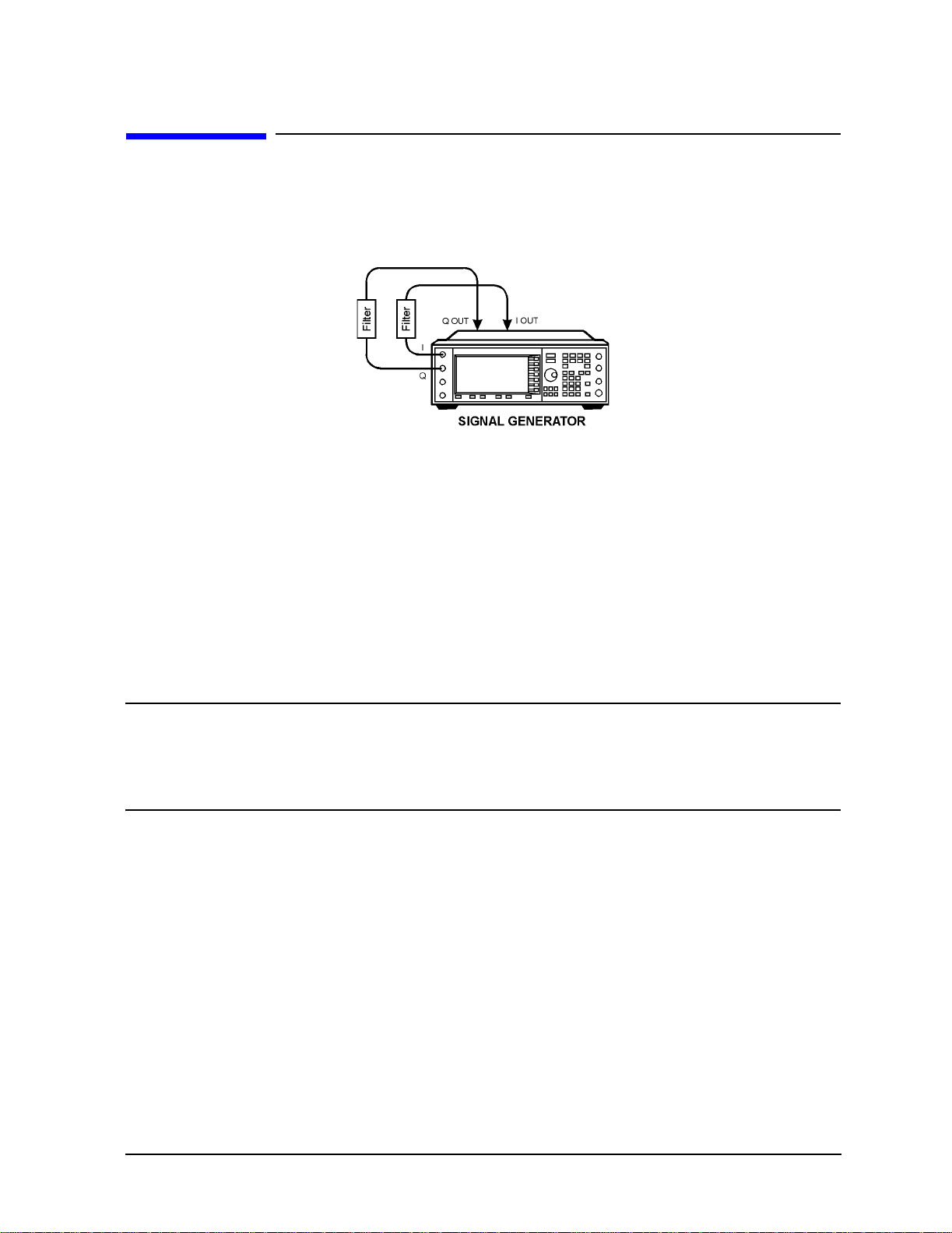
ESG Family Signal Generators Using Functions
Options UND & UN5 Using External Reconstruction Filters
Using External Reconstruction Filters
You can use external reconstruction filters with the arbitrar y waveform generator and the
CDMA waveform generator by f ollo wing the instruc tions l isted in t his secti on. Refe r to th e
figure below.
1. Using four 50-ohm BNC cables of identical length and filters with matching filter del a y
values, connect the filters betwe en the rear panel I-OUT and Q-OUT connectors and the
front panel I and Q input connectors.
2. Press
I/Q > I/Q Source > Ext I/Q. This connects t he i np ut of the I/Q mod u la tor to the fr on t
panel I and Q input connectors.
3. For CDMA signals, press
IS-95A > CDMA Define > Reconstruction Filter > Through. This disables the internal
Mode > ARB Waveform Generator (if it appears) > CDMA Formats >
reconstruction filters.
For arbitrary waveform generator signals, press
appears) >
Dual ARB > ARB Setup > Reconstruction Filter > Through.
Mode > ARB Waveform Generator (if it
NOTE This step is not necessary as lo ng as you are us ing a recons tructi on f ilter that
has a smaller bandwidth than the active internal reconstruction filter. For
example, if the internal reconstruction filter is set to 2.5 MHz and you would
like to use a 1 MHz external filter, it is not necessary to set the internal
reconstruction filter to Through.
Dual Arbitrary Waveform Generator User’s and Programming Guide 2-45
Page 62

Using Functions ESG Family Signal Generators
Using the Multitone Waveform Generator Options UND & UN5
Using the Multitone Waveform Generator
The examples in this section provide information on how to create a multit one waveform
(on page 2-47), and how to use a stored multitone waveform (on page 2-52).
Table Editor Basics
While the following examples provide information specific to the multitone table editor
(shown in the following figure), they do not go into detail on every possible way to edit
information. The section “Table Editor Basics” on page 2-2 covers in detail many of the
features common to most table editors.
NOTE The signal generator firmware has been updated to include a feature that
allows you to set the rela ti ve power levels f or ea ch m u l ti tone waveform
generator tone. These ins tructions refle ct this firmw are change . If your signal
generator is not equipped with this latest firmw are , your multitone wa veform
generator will not have the ability to set the relative power levels of the tones .
The steps that you use to create a multitone wa veform will not inc lude setting
the relative power leve ls.
To upgrade your signal generator firmware to the most current version
available, contact your nearest Agilent Technologies Sales and Service office.
2-46
Dual Arbitrary Waveform Generator User’s and Programming Guide
Page 63

ESG Family Signal Generators Using Functions
Options UND & UN5 Using the Multitone Waveform Generator
Creating a Multitone Waveform
The following example walks you through creating and storing a simple 5-tone waveform.
You can use this example to familiarize yourself with the various parameters that are
available to customize this type of waveform.
Initialize the Multitone Table Editor
The first step in creating a multitone waveform is to set the number of tones and the
frequency spacing between those tones . This is termed initializing t he table editor, because
this is the only way to set the frequencies and number of tones, and when you change
either the number of tones or the freque ncy spacing, the relative power level of all tone s is
set to 0.00 dB, the phase of all tones is set to zero, and all tones are turned on.
1. Preset the signal generator, then press
Multitone. The signal generator displays the multitone table editor, which will look
Mode > ARB Waveform Generator (if it appears) >
similar to the following figure.
2. Press Initialize Table > Number of Tones.
3. Using the front panel knob, change the number of tones to 5.
Note that the
Number of T ones softkey now disp lays the number o f tones that w as entere d
(5 in this example), but the number of tones in the table editor has not changed.
4. Press
Freq Spacing.
Tones are evenly spaced about zero. When there are an even number of tones defined
(as shown in the previous figure), the center two tones are placed on either side of zero.
For an odd number of tones (as you specified in step 3), the center tone is placed at zero.
Also, if you set the frequency spacing less than approximately 5 kHz, the ALC can
interact with the tones, causing some distortions as evidenced by intermodulation
products outside the desired tones. To eliminate this effect, turn off the ALC.
5. Using the front panel number keys , enter
20, then press the kHz softkey to terminate the
entry.
Dual Arbitrary Waveform Generator User’s and Programming Guide 2-47
Page 64

Using Functions ESG Family Signal Generators
Using the Multitone Waveform Generator Options UND & UN5
Note in the figure below that the Freq Spacing softkey now displays the new spacing
value, but that the values in the table editor have not changed.
NOTE The Initialize Phase Fixed Random and the Random Seed Fixed Random softkeys are
displayed in the figure above. These softkeys a re not used in this procedure as
described but they could be used if you wanted to set the tones to random
phases.
•The
Initialize Phase Fixed Random softkey is used to select either fixed or random
phase settings for the tones. Selecting the
all of the tones to 0 d egree s . Selec ting t he
Fixed softkey will set the phase of
Random softkey will set the phase of
the tones to randomly generate d phase value s based on s elected sett ing of the
Random Seed Fixed Random softkey.
•The
Random Seed Fixed Random softkey is used to select either a fixed seed or a
random seed for the randomly generated phases. Selecting the
will generate the same random phases after each initialization. Selecting the
Random softkey will generate new phases after each initialization.
6. To enter the new values into the table editor, press the softkey
Fixed softkey
Done.
2-48
Dual Arbitrary Waveform Generator User’s and Programming Guide
Page 65

ESG Family Signal Generators Using Functions
Options UND & UN5 Using the Multitone Waveform Generator
Note that there are now five tones listed in the table editor, and that the values listed in
the
Freq Offset column are 20 kHz apart, w ith the center tone at 0.000 kHz.
Set the Power
When the table is firs t initialized, all power values are set to 0.00 dB. The power levels set
in the table editor are relative to an arbitrary 0 dB reference. The cumulative power of all
of the tones is equal to the amplitude shown in the amplitude area of the display. You can
use the table editor to change the relative power l evel of any tone.
1. Using the front panel arrow keys, highlight the P ower entry for the second tone.
2. Select the softkey
3. Using the front panel number keys, press
Edit Item.
+/- > 4.5, then press the dB softkey to terminate
the entry.
The second tone is updated with a relative power level of −4.50 dB, and phase value of
the second tone is highlighted.
Dual Arbitrary Waveform Generator User’s and Programming Guide 2-49
Page 66

Using Functions ESG Family Signal Generators
Using the Multitone Waveform Generator Options UND & UN5
Set the Phase
When the table is first initialized, all phases are 0; this is a phase aligned condit ion, and
the peaks of each tone will all add up to a high peak at points in the waveform. By
changing the phases in the table editor, you can make different levels of peaks. You can
view this peak information using the View Statistics → CCDF function (
ARB Waveform Generator (if it ap pears) > Multitone > (More 1 of 2) > Waveform Statistics >
Plot CCDF).
Mode >
1. Using the front panel arrow keys, highlight the Phase entry for the third tone.
2. Select the softkey
3. Using the front panel number keys, enter
Edit Item.
123, then press the deg softkey to terminate
the entry.
The third tone is updated with a phase of 123 degrees, and state of tone 4 is
highlighted.
Remove any Unwanted Tones
You can remove a tone to view, for example, the intermodulation caused by the remaining
tones.
1. Using the front panel arrow keys, highlight the State entry for the fourth tone.
2. Select the softkey
2-50
Toggle State.
Dual Arbitrary Waveform Generator User’s and Programming Guide
Page 67

ESG Family Signal Generators Using Functions
Options UND & UN5 Using the Multitone Waveform Generator
Note that in the State column, the fourth tone now displays Off.
Save the Multitone Setup.
Now that you have created a custom multitone waveform, you can save it for future use.
When changes made to the default table have not been stored,
(UNSTORED) appears as
shown in the following figure. Also, when you load and edit a Multitone setup table from a
stored file (see “Using a Stored Multitone Waveform” on page 2-52 for instructions on how
to do this),
1. In the softkey menu, press
(Modified)is displayed after the file name until you store the w aveform.
More 1 of 2 > Load/Store > Store To File . The catalog of files
appears, with the name of stored files, and amount of memory used and available (in
bytes).
2. Name this file
Edit Keys > Clear Text > 5 > VWXYZ_$ > _ > OPQRSTU > T > OPQRSTU > O > HIJKLMN > N >
ABCDEF > E and terminate the entry by pressing Enter. You now have a file called 5_TONE
5_TONE. If there is already a file highlighted in the CDMA catalog, press
stored in the signal generator’ s volat ile ARB memory.
For complete instructions on naming a file, refer to “Storing a Custom CDMA State to
Memory” on page 2-11.
Dual Arbitrary Waveform Generator User’s and Programming Guide 2-51
Page 68

Using Functions ESG Family Signal Generators
Using the Multitone Waveform Generator Options UND & UN5
Using a Stored Multitone Waveform
Once you have created and stored a multitone waveform, you can use that information as
described in the following steps.
Selecting a Multitone Waveform
1. Press the front panel
Multitone.
2. To display the catalog of stored multitone files, press
3. Highlight the file you want to use, then press
Confirm Load From File. The information from the file is loaded and displayed in the table
Mode key, then press Arb Waveform Generator [if it appears] >
(More 1 of 2) > Load/Store.
Load From Selected File >
editor, as shown in the figure below.
2-52
Dual Arbitrary Waveform Generator User’s and Programming Guide
Page 69

ESG Family Signal Generators Using Functions
Options UND & UN5 Using the Multitone Waveform Generator
Turning On a Multitone Modulation
Once you have selected a multitone waveform, use the following steps to turn it on.
1. Press
2. In the Multitone menu, press the softkey
Note that the front panel annunciators
3. Press the front panel
4. Press the front panel
5. If necessary, press the front panel
Return to open the Multitone menu.
Multitone Off On to highlight On.
M–Tone and I/Q turn on.
Frequency hardkey and then set the desired fr equency.
Amplitude hardkey and then set the desired amplitude.
Mod On/Off hardkey until the MOD ON annunciator
appears. This applies the custom modulation to the carrier.
6. If the RF is not on (the
hardkey. The display annunciator changes to
RF OFF annunciator is displayed) , press the front panel RF On/Off
RF ON, and the custom modulated signal
is available at the RF OUTPUT connector.
NOTE If you edit parameters in a multitone modulation after you turn multitone
on, select the softkey
Apply Multitone to regenerate the updated multitone
waveform.
Dual Arbitrary Waveform Generator User’s and Programming Guide 2-53
Page 70

Using Functions ESG Family Signal Generators
Building a Waveform Sequence Options UND & UN5
Building a Waveform Sequence
Follow the guidelines in this section to learn how to build waveform sequences from
waveform segments using the d ual ar bitrary w a vefor m generat or. (Options UND and UN5
are both required.)
In this example, you will generate two different types of CDMA waveform segments,
a 64 channel forward and a 9 channel forward signal. After you have the two waveform
segments stored in NVARB memory, you will build a sequence using each one of these
waveform segments.
NOTE There are two kinds of arbitrary waveform generat or me mory : ARB memory
and NVARB memory.
ARB memory is volatile. Data held in ARB memory is destroyed if the signal
generator’s line power is cycled.
NVARB memory is non-volatile. Data held in NVARB memory is not
destroyed if the signal generator’s line power is cycled.
For more information on ARB and NVARB memory, see “Managing Volatile
and Non-Volatile ARB Memory” on page 4-4.
Generating the First Waveform
There are two ways to provide waveforms for use by the sequencing and playback sections
of the signal generator. You can either download a waveform via GPIB or generate a
waveform in a CDMA format. For information on downloading waveforms via GPIB, see
“Downloading Waveform F iles Into Memory” on page 2-72. The following procedure shows
how you can generate a waveform using the IS-95A CDMA (Option UN5) format. For
information on generating waveforms using other CDMA formats, refer to the user’s and
programming guide for the specific CDMA format option.
To generate the first wavef orm using the CDMA format:
1. Press the front panel
2. Press
3. Press the
Mode > Arb Waveform Generator (if it appears) > CDMA Formats > IS-95A.
Setup Select softkey, then press 64 Ch Fwd to select a 64-channel forward CDMA
template.
Preset key.
2-54
Dual Arbitrary Waveform Generator User’s and Programming Guide
Page 71

ESG Family Signal Generators Using Functions
Options UND & UN5 Building a Waveform Sequence
4. Press CDMA Off On until On is highlighted. The signal gener ator generates the 64 channel
forward CDMA waveform and stores it in ARB (volatile) memory with the name
AUTOGEN_WAVEFORM (the default name given to any waveform generated in the CDMA
format).
NOTE There can only be one AUTOGEN_WAVEFORM waveform in ARB memory at any
given time.
Therefore, you must rename this file,clearing the way for a second CDMA
waveform.
5. Press
Return twice, then press Dual ARB. This returns you to the main arbitrary
waveform generator menu.
Renaming the First Waveform as a Waveform Segment
1. Press Waveform Segments. This opens a menu that enables you to rename the waveform
as a waveform segment. Later in the process, the two waveform segments, 64 channel
forward and 9 channel forward, will be combined to form a waveform sequence.
2. Press
More (1 of 2) > Rename Segment > Editing Keys > Clear Text. You are now read y to enter a
new file name for the 64 channel forward CDMA w aveform segment.
Dual Arbitrary Waveform Generator User’s and Programming Guide 2-55
Page 72

Using Functions ESG Family Signal Generators
Building a Waveform Sequence Options UND & UN5
3. Press 64 > ABCDEFG > C > HIJKLMN > H > ABCDEFG > F > Enter. The waveform seg ment fil e
name has now been changed to
64CHF.
Generating the Second Waveform
1. Press Mode > Arb Waveform Generator (if it appears) > CDMA Formats > IS-95A.
2. Press
Setup Select > 9 Ch Fwd to select a 9-channel forward CDMA template.
3. The signal generator generates the 9 channel forward CDMA waveform and stores it in
ARB (volatile) memory with the name
AUTOGEN_WAVEFORM, the default name given to
any waveform generated in the CDMA format. (This is why you renamed the 64
channel forward CDMA waveform, so as not to over write it with this 9 channel forward
CDMA waveform.)
4. Press
Return twice, then press Dual ARB. This will return you to the main arbitrary
waveform generator menu.
Renaming the Second Waveform as a Waveform Segment
1. Press Waveform Segments. This opens a menu that enables you to rename the wa veform
as a waveform segment. Use the front panel knob to highlight
2. Press
More (1 of 2) >Rename Segment > Editi ng Keys > Clear Text. You are now ready to enter a
new name for the 9 channel forward CDMA waveform segment.
3. Press
changed to
9 > ABCDEFG > C > HIJKLMN > H > ABCDEFG > F > Enter. The name has now been
9CHF.
AUTOGEN_WAVEFORM.
4. Press
2-56
Return. This will take you to the main arbitrary waveform generator menu.
Dual Arbitrary Waveform Generator User’s and Programming Guide
Page 73

ESG Family Signal Generators Using Functions
Options UND & UN5 Building a Waveform Sequence
Building a Waveform Sequence from Two Wa vefor m Seg ments
1. Press Waveform Sequences > Build New Waveform Sequence. This opens a menu for building
new waveform sequences . The left side of the displa y is a catalog listing of the w avefor m
segments and sequences in ARB memory. The right side of the display is a sequential
listing of waveform segments that define the waveform sequence.
2. Press
waveform segments. Use the arrow keys or the front panel knob to highlight
3. Press
Insert Waveform. This moves the highlight bar over to the catalog listing of
64CHF.
Insert Selected Waveform. This inserts one repetition of the 64 channel forward
CDMA waveform segment into the sequence playback listing on the right side of the
display. Under the table heading
heading
Rep# you will see 1. The sequencer has now been programmed to pla y bac k one
Waveform you will see ARB:64CHF, and under the table
repetition of the 64 channel forward CDMA waveform segment.
Dual Arbitrary Waveform Generator User’s and Programming Guide 2-57
Page 74

Using Functions ESG Family Signal Generators
Building a Waveform Sequence Options UND & UN5
4. Use the arrow keys or the front panel knob to highlight the 9CHF waveform segment.
Press
Insert Selected Wav eform. This inserts one repeti tion of the 9 channe l forw ard CDMA
waveform segment into the sequence playback listing below the 64 channel forward
waveform segment. Under the table heading
ARB:9CHF, and under the table heading Rep# you will see an additional 1.
Waveform you will see the addition of
5. Press
Done Inserting. The sequence has now been defined as one repetition of
the 64 channel forward CDMA waveform segment followed by one repetition of
the 9 channel forward CDMA waveform segment.
Editing the First and Second Waveform Segment Repetitions
1. Use the front panel knob or the arrow keys to highlight the ARB:64CHF sequence entry.
Press
Press
changed to
Edit Repetitions. Repetitions: 1 is displayed in the active entry area of the display.
5 > Enter. The number of repetitions for the sequence entry ARB:64CHF has been
5 and the highlight has moved over the sequence ARB:9CHF entry.
2-58
Dual Arbitrary Waveform Generator User’s and Programming Guide
Page 75

ESG Family Signal Generators Using Functions
Options UND & UN5 Building a Waveform Sequence
2. Press Edit Repetiti ons. Repetitions: 1 is displayed in the active entry area of the display.
Press:
changed to
8 > Enter. The number of repetitions for the sequence entry ARB:9CHF has been
8.
Naming and Storing the Waveform Sequence
1. Press Name and Store. Store: is displayed in the active entry area of the display.
2. Using the alphabetical softkeys and the numeric keypad, name the sequence
64CHFX5+9CHFX8. After inputting the sequence name and pre ssing Enter, the sequence is
automatically stored in the sequence (Seq) section of the signal generator’s memor y
catalog.
Dual Arbitrary Waveform Generator User’s and Programming Guide 2-59
Page 76

Using Functions ESG Family Signal Generators
Building a Waveform Sequence Options UND & UN5
Playing the Waveform Sequence
1. Press Return twice to return to th e top level men u (ARB Off On is the first softkey).
2. Press
Select Wavefo rm. This opens a menu from which you can select waveform segments
or waveform sequences to be played.
3. Use the arrow keys or the front panel knob to highlight the wavef orm seque nce
64CHFX5+9CHFX8. Press Select W aveform. This selec ts t he waveform sequence t o be p la yed
through the signal generator’s I/Q section .
4. Press
ARB Off On until On highlights. The I/Q and ARB annunciators appear. This
activates the wavefor m and plays it out of the dual arbitrary wavef orm generator.
To s ee this signal at the RF output, enter the appropriate frequency and amplitude
settings (for example, press
carrier at 890.01 MHz at a power level of −10 dBm), activate the modulation (
to
On), and activate the RF output (RF Off On set to On).
Frequency > 890.01 > MHz and Amplitude > −10.0 > dBm,for a
Mod Off On set
2-60
Dual Arbitrary Waveform Generator User’s and Programming Guide
Page 77

ESG Family Signal Generators Using Functions
Options UND & UN5 Using Markers
Using Markers
The signal generator has two markers that you can place o n a w aveform s egment; markers
provide auxiliary output signals that are synchronized with a w aveform segment. You can
construct these output signals as a trigger signal to synchronize another instrument to a
given portion of a waveform.
In some situations, it can be useful to use the markers to generate a clock signal. Using a
CDMA waveform as a waveform segment (an
ARB sample clock frequency is a multiple of the chip rate. Using markers and the
#Skipped Points feature, you can construct a clock at the chip rate easily.
Placing Markers on a Waveform Segment
Marker 1 → Event 1
AUTOGEN_WAVEFORM ARB), for example, the
Waveform Data
I Channel Bit 14
Event 1 Connector
Waveform
I Data Bit 14
Waveform point
For Marker Polarity = Positive
For Marker Polarity = Negative
n point n+1 point n+2 point n+3
...
Positive
Event 1
±
Marker
Polarity
Dual Arbitrary Waveform Generator User’s and Programming Guide 2-61
Negative
Page 78
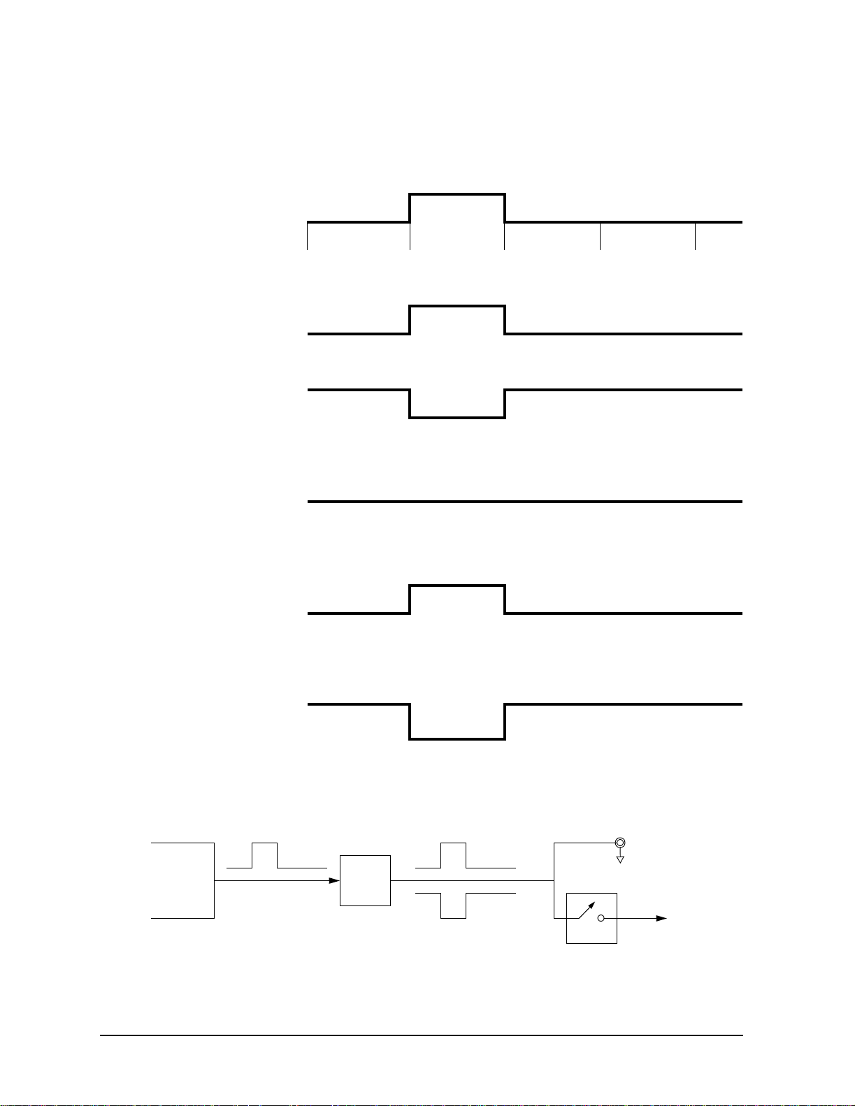
Using Functions ESG Family Signal Generators
r
Using Markers Options UND & UN5
Marker 2 → Event 2
Waveform Data
I Channel Bit 15
Waveform point n point n+1 point n+2 point n+3
...
Event 2 Connector
RF Output
RF Output
Marker 2 to RF blank = Off
Marker Polarity = Positive
RF Output
Marker 2 to RF blank = On
Marker Polarity = Negative
For Marker Polarity = Positive
For Marker Polarity = Negative
RF Unblanked
Marker 2 to RF blank = Off
RF Unblanked
RF Blanked RF Blanked
RF Unblanked RF Unblanked
RF Blanked
2-62
Waveform
I Data Bit 15
±
Marker
Polarity
Positive
Negative
Marker 2 to
RF Blank
Off On
Event 2
Marker 2
Blanks RF
when Marke
is Low
Dual Arbitrary Waveform Generator User’s and Programming Guide
Page 79

ESG Family Signal Generators Using Functions
Options UND & UN5 Using Markers
Placing a Marker at the Beginning of the Waveform Segment
You can put a marker at the beginning of a segment to create a trigger output that is
synchronous with the start of that w aveform segment.
1. Create/select a waveform segment (for details, refer to “Generating the First Waveform”
on page 2-54).
2. Press:
Waveform Utilities > Set Markers > Set Marker On First Point
Mode > ARB Waveform Generator (if it appears) > Dual ARB > Waveform Segments >
This sets Marker 1 (selected by default) on the first point in the waveform segment.
Checking a Marker
Once you set a marker on a waveform segment, you can see the results at the Event 1/2
output (Event 1 for this example).
1. With the desired segment selected, press
Return three times to display the Dual ARB
softkey menu.
2. Press
ARB Off On to select On. The ARB and the I/Q annunciators turn on.
3. Connect an oscilloscope to the Event 1 output, and trigger on the Event 1 signal. When
a marker is present, a trigger occurs .
Placing a Marker Across a Range of Points
You can place a marker across a range of points, as well as at a single point.
1. Create/select a wa veform segment (for d etails , refer to “Generating the F irst Waveform”
on page 2-54).
2. Press
Waveform Utilities > Set Markers > Marker 1 2 (to select marker 2) >
Set Marker On Range of Points.
Mode > ARB Waveform Generator (if it appears) > Dual ARB > Waveform Segments >
3. Set the first and last points fo r th e marker, then press
Apply To Waveform.
If you enter a value for eit her the firs t marker point or the la st marker po int that woul d
make the first marker point occur after the last, the last marker point is automatically
adjusted to match the first marker point.
You can check this marker as described previously (at the Event 2 output for this
example).
Dual Arbitrary Waveform Generator User’s and Programming Guide 2-63
Page 80

Using Functions ESG Family Signal Generators
Using Markers Options UND & UN5
Placing Repetitively–Spaced Markers
You can set a marker across a range of points, and designate spaces at a specific interval
within that range. This gives you the effect of multiple markers within the range that you
specify. You can use this feature to generate a clock signal.
1. Create/select a wa veform segment (for d etails , refer to “Generating the F irst Waveform”
on page 2-54).
2. Press
Waveform Utilities > Set Markers > Set Marker On Range of Points.
Mode > ARB Waveform Generator (if it appears) > Dual ARB > Waveform Segments >
3. Set the first and last points for the marker.
4. To def ine the spacing that you want between the markers , press
# Skipped Points, then set
the number of points.
For example, a skip of 2, would produce a marker (M) across a given range, with a
pattern of two skipped points (w) within that range:
wwwwwwwwwwwwwMwwMwwMwwMwwMwwwwwwwwwwwwww
MarkerRange
5. Press
Apply To Waveform.
Using Marker 2 to Blank the RF Output
Using the Marker 2 to RF Blank feature, the range of marker points that you set in this
example blanks the RF output. Changing the range changes the blanking interval. When
Marker 2 to RF Blank is enabled, the RF output is blanked whenever marker 2 is low (as
seen at the Event 2 BNC c onnector ). When Mar ker 2 is high, the RF output is normal, and
its level is controlled by the ALC (when ALC is on).
NOTE This applies to Marker 2 only. Marker 1 does not blank the RF output.
1. Create/select a wa veform segment (for d etails , refer to “Generating the F irst Waveform”
on page 2-54).
2. Press
Marker Polarity Neg Pos (to select negative polarity) > Marker 2 To RF Blank Off On (to turn
Mode > ARB Waveform Generator (if it appears) > Dual ARB > ARB Setup >
blanking on).
NOTE If you leave the marker polarity positive, the RF is blanked until the marker
goes high (see “Marker 2 → Event 2” on page 2-62).
3. Press
marker 2) >
4. Set the first and last points fo r th e marker, then press
Return > Waveform Segments > Waveform Utilities > Set Markers > Marker 1 2 (to select
Set Marker On Range of Points.
Apply To Waveform.
You can check this marker as described previously (at the Event 2 output for this
example).
2-64
Dual Arbitrary Waveform Generator User’s and Programming Guide
Page 81

ESG Family Signal Generators Using Functions
Options UND & UN5 Using Markers
Using Markers in a Waveform Sequence
A waveform sequence comprises wa veform segments . When you combine segments to fo rm
a sequence, you can enable or disable marker 1 and/ or marker 2 on a segment-by-segment
basis.
When you select a sequence to output, the markers embedded in any one segment of that
sequence are output only if the sequence marker for that segment is enabled (toggled on).
This makes it possible to output markers for some segments in a sequence, but not for
others.
Waveform
I Data Bit 14
Waveform
I Data Bit 15
Sequence
Marker 1
Sequence
Marker 2
±
Marker
Polarity
±
Event 1
Event 2
RF Blanking
Marker 2 to
RF Blank
Off On
Dual Arbitrary Waveform Generator User’s and Programming Guide 2-65
Page 82

Using Functions ESG Family Signal Generators
Using Markers Options UND & UN5
Toggling Markers in an Existing Wav eform Sequence
In a waveform sequ ence , you can toggle the marker s of eac h segment inde pendentl y. When
you build a waveform sequence , the markers on each segment ar e in the last marker toggle
state that was used.
1. Press
Mode > ARB Waveform Generator (if it appears) > Dual ARB > Waveform Sequences.
2. Select the desired waveform sequence.
3. Press
Edit Selected Waveform Sequence. Note that the entries in the Mk column for each
segment indicates whether a marker is on. No entry in that column means that both
markers are off.
Marker
Column
This entry
shows both
markers on.
4. Using the front panel knob, move the highlight to select the desired segment.
5. Press
Toggle Marker 2). You can toggle either one of the markers, or both.
Toggle Markers, then select the marker that you wish to toggle (Toggle Marker 1 or
6. Use the front panel arrow keys to move the highlight to the next desired segment, and
toggle the markers for that segment. Continue with the remaining segments.
7. When you have all markers set as you wish, press
Return, where you can name and store
the edited waveform seq uence.
2-66
Dual Arbitrary Waveform Generator User’s and Programming Guide
Page 83

ESG Family Signal Generators Using Functions
Options UND & UN5 Using Markers
Toggling Markers As You Create a Waveform Sequence
You can combine waveform segments to create a waveform sequence, and toggle the
markers of each segment independently.
1. Press
Build New Waveform Sequence.
Mode > ARB Waveform Generator (if it appears) > Dual ARB > Waveform Sequences >
2. Refer to “Building a Waveform Sequence ” on page 2-54 for details on how to build a
waveform sequence.
3. To toggle markers:
a. Press
Mode > ARB Waveform Generator (if it appears) > Dual ARB > Waveform Sequences.
b. Select the desired waveform sequence.
c. Press
Edit Selected Waveform Sequence. Note that the Mk entry for each segment
indicates whether a marker is on. No entry in that co lumn means that both markers
are off.
d. Using the front panel knob, move the highlight to select the desired segment.
e. Press
Toggle Marker 2). You can toggle either one of the markers, or both.
Toggle Markers, then select the marker that you wish to toggle (Toggle Marker 1 or
f. Use the front panel arrow keys to move the highlight to the next desired
segment, and toggle the markers for that segment. Continue with the remaining
segments.
g. When you have all markers set as you wish, press
Return, where you can name and
store the edited wa ve form sequence.
Dual Arbitrary Waveform Generator User’s and Programming Guide 2-67
Page 84

Using Functions ESG Family Signal Generators
Scaling Waveform Segments Options UND & UN5
Scaling Waveform Segments
The scaling feature can be used to scale waveform segments. It scales the waveform
segments by changing the peak-to-peak output value of the selected waveform segment to
a desired percentage of its full-scale value. Scaling has two purposes. First, scaling can be
used to reduce the distortion that may be present with the waveform set at its full scale.
Scaling can also be used to scale I and Q rear panel output levels of IS-95A signals
generated by Option UN5. By setting scaling for the AUTOGEN_WAVEFORM
waveform, you can change th e I and Q signals from the def ault value . A w avef orm segment
must be selected in the volatile ARB waveform memory befor e it can be scaled. The scaling
can be set from 1 to 100% in 0.01% increments.
NOTE The output of the Dual ARB waveform is determined by the least significant
14 bits of a 2-byte integer (see “Waveform Composition” on page 4-6). As the
waveform is scaled down, it can lose bits of resolution. Once a bit of resolution
is lost, it can not be regained by increasing the scaling value of the waveform.
To s cale a waveform segment:
1. If the signal generator is in remote mode, first press the
generator to local control. Press the
2. Press
Arb Waveform Generator (if it appears). Then press Dual ARB > Waveform Segments.
Mode key.
Local key to return the sig n a l
3. If you want to scale a waveform segment that is not in the volatile ARB waveform
memory, press
Load Store so that Load is selected. If more than one waveform segment is
present in the non-volatile ARB waveform memory (NVARBI), use the directional
arrows to highlight the waveform segment that you want to scale. Then press
Load Se gment From NVARB Memory to load the segment to the volatile ARB waveform
memory (ARBI). The following figure shows the display after loading the segment,
5-TONE-A, into volatile ARB memory.
2-68
Dual Arbitrary Waveform Generator User’s and Programming Guide
Page 85

ESG Family Signal Generators Using Functions
Options UND & UN5 Scaling Waveform Segments
4. Press Load Store so that Store is selected. If more than one waveform segment is present
in the volatile ARB waveform memory (ARBI), use the directional arrows to highlight
the waveform segment that you want to scale. Press
Waveform Utilities > Set Scaling.
5. Press the
% terminator softkey. The scaling softkey now reads Scaling 50.00%, as shown in the
Scaling 100.00% softkey. Use the n um e ri c k eypad to enter 5, 0. Then press the
following figure.
6. Press the
Apply To Waveform softkey to scale the waveform segment to 50% and return to
the previous menu, as shown in the following figure.
Dual Arbitrary Waveform Generator User’s and Programming Guide 2-69
Page 86

Using Functions ESG Family Signal Generators
Clipping Waveform Segments Options UND & UN5
Clipping Waveform Segments
Clipping limits power peaks in waveform segments by clipping the compo sit e I/ Q
waveform (or I and Q separ ately) to a sele cted per centage of its highest peak. Clipp ing can
be set from 10 to 100% in 0.01% increments. You must select a waveform segment in the
volatile ARB waveform memory before it can be clipp ed. For more information, refer to
“Understanding Baseband Clipping” on page 4-10.
Perform the foll owing proc edure to configure and apply clipping to a wave form segment.
1. Press the
2. Press
Mode key.
Arb Waveform Generator (if it appears). Then press Dual ARB > Waveform Segments.
3. If you want to clip a waveform segment that is not in the volatile ARB waveform
memory, press
Load Store so that Load is selected. If more than one waveform segment is
present in the non-volatile ARB waveform memory (NVARBI), use the directional
arrows to highlight the waveform segment that you want to scale. Then press
Load Segment From NVARB Memory to load the segment to the volatile ARB waveform
memory (ARBI). The following figure shows the display after loading the segment,
5-TONE-A, into volatile ARB memory.
4. Press
Load Store so that Store is selected. If more than one waveform segment is present
in the volatile ARB waveform memory (ARBI), use the directional arrows to highlight
the waveform segment that you want to clip. Press
Waveform Utilities > Clipping to access
the clipping setup menu.
5. Notice that the
selection clips the combined I and Q waveform. Alternatively,
Clipping Type |I+jQ| |I|,|Q| softkey default is |I+jQ| (circular clipping). This
|I|,|Q| (rectangular
clipping) clips the I and Q waveforms separately. Use the default selection for this
example.
2-70
Dual Arbitrary Waveform Generator User’s and Programming Guide
Page 87

ESG Family Signal Generators Using Functions
Options UND & UN5 Clipping Waveform Segments
6. Press Clip |I+jQ| To and enter 80 percent. Notice t hat 80.0% is shown below the Clip |I+jQ| To
softkey, as shown in the following figure.
7. Press the
Apply To Waveform softkey to clip the waveform segment to 80% and return to
the previous menu, as shown in the following figure.
Dual Arbitrary Waveform Generator User’s and Programming Guide 2-71
Page 88

Using Functions ESG Family Signal Generators
Downloading Waveform Files Into Memory Options UND & UN5
Downloading Waveform Files Into Memory
Follow the guidelines in this section to learn how to download waveform files into the
signal generator’s ARB memory. (Option UND is required.) For inf ormation on system
interface, including GPIB and RS-232, refer to the programming guide.
Downloading Waveform Files Into ARB Memory
Downloading waveforms into volatile (ARB) memory is much quicker than downloading
waveforms into non-volatile (NVARB) memory. If you want to store waveforms in NVARB
memory, first follow the instructions to download into volatile ARB memory and then copy
or move the waveforms internally into NVARB memory. See the following section
titled, “Transferring Waveforms Between ARB and NVARB Memory.”
Use the following SCPI command lines to download a waveform to ARB memory:
MMEM:DATA "ARBI:<waveform_name>",<I_waveform_data>
This command downloads the I values for your waveform. The variable <waveform_name>
denotes the name that will be associated with the downloaded waveform data within the
signal generator and therefore must be the same for both I and Q downloads.
MMEM:DATA "ARBQ:<waveform_name>",<Q_waveform_data>
This command downloads the Q values for your waveform.
The signal generator will associate t he I w a vefor m val ues and the Q w a vefo rm values, and
drive the I and Q modulators with the stored waveform in the baseband generator. If only
one of the two required c ommands is execut ed (I valu es only o r Q val ues only), the missing
data will be set to values corresponding to a 0 V output.
Sample Command Line
A sample command line:
MMEM:DATA "ARBI:<waveform_name>",#ABC
"<waveform_name>" the name of the wavefor m fi l e wit h i n th e si gn a l g enerator
A the number of decimal digi t s to fo l lo w i n B.
B a decimal number specifying the number of data bytes in C.
C the binary waveform data in 2-byte integers .
2-72
Dual Arbitrary Waveform Generator User’s and Programming Guide
Page 89

ESG Family Signal Generators Using Functions
Options UND & UN5 Downloading Waveform Files Into Memory
Example 1
MMEM:DATA "ARBI:WAVEFORM1" > #232<32 bytes of data>
A B
WAVEFORM1
2 defines the number of decimal digits to follow in B. This variable is
the waveform name
C
represented by A in the sample command line.
32 denotes how many bytes of data are to follow. This variable is represented
by B in the sample command line.
<32 bytes
of data>
the binary waveform data in 2-byte integers. Dat a order i s defined a s Most
Significant Bit (first) through Least Significant Bit (las t). This variable is
represented by C in the sample command line.
Querying the Waveform Data
Use the following SCPI command line to upload waveform data from the ARB memory to
the personal computer:
MMEM:DATA? "ARBI:<waveform_name>"
MMEM:DATA? "ARBQ:<waveform_name>"
Waveform Downloading Using BASIC for Windows
The following program shows you how to use download waveforms using BASIC for
Windows.
First, th e I wavefo rm data is put i n to an a rr ay of in tegers calle d
waveform data is put int o an array of integers called
Qwfm_data. The variable Nbytes is set
Iwfm_data and the Q
to equal the number of bytes in the I waveform data. This should be twice the number of
integers in
Iwfm_data, since an integer is 2 bytes. Input integers must be between 0 and
16383.
In the
Output commands, th e USING “#,K” formats the data. The pound symbol (#)
suppresses the automatic EOL (End of Line) output. This allows multiple output
commands to be concatenated as if they were a single output. The “K” instructs BASIC to
output the following numbers or strings in the default format.
5 Npoints=20
10 ALLOCATE INTEGER Iwfm_data(1:Npoints),Qwfm_data(1:Npoints)
15 DEG
20 FOR I=1 TO Npoints
25 Iwfm_data(I)=INT(8191*(COS(I*360/Npoints))+8192)
30 Qwfm_data(I)=INT(8191*(COS(I*360/Npoints))+8192)
35 NEXT I
40 Nbytes=2*Npoints
45 Assign @ESG to 719
50 Assign @ESGb to 719; FORMAT MSB FIRST
60 Nbytes$=VAL$(Nbytes)
70 Ndigits$=VAL$(LEN$(Nbytes$))
80 OUTPUT @ESG USING "#,K";"MMEM:DATA ""ARBI:testfile"", #"
90 OUTPUT @ESG USING "#,K";Ndigits$
Dual Arbitrary Waveform Generator User’s and Programming Guide 2-73
Page 90

Using Functions ESG Family Signal Generators
Downloading Waveform Files Into Memory Options UND & UN5
100 OUTPUT @ESG USING "#,K";Nbytes
110 OUTPUT @ESGb;Iwfm_data(*)
120 OUTPUT @ESG;
130 OUTPUT @ESG USING "#,K";"MMEM:DATA ""ARBQ:testfile"", #"
140 OUTPUT @ESG USING "#,K";Ndigits$
150 OUTPUT @ESG USING "#,K";Nbytes$
160 OUTPUT @ESGb;Qwfm_data(*)
170 OUTPUT @ESG;
180 Assign @ESG TO *
190 Assign @ESGb to *
200 END
Table 2-1
5: Sets the number of points in the waveform.
10: Defines arrays for I and Q waveform points. Sets them to be integer arrays.
15: Sets BASIC to use degrees for cosine and sine functions.
20: Sets up loop to calculate waveform points.
25: Calculates I waveform points.
30: Calculates Q waveform points.
35: End of loop.
40: Calculates number of bytes in I or Q waveform.
45: Opens an I/O path to the signal generator using GPIB. 7 is the address of the
GPIB card in the computer > and 19 is the address of the signal generator. This
I/O path is use d to send ASCII data to the signal generator.
50: Opens an I/O path for sending binary data to the signal generator. FORMAT MSB
FIRST is needed to send the 2 bytes of each integer to the signal generator in the
correct order.
60: Creates an ASCII string representation of the number of bytes in the waveform.
70: Finds the number of digits in Nbytes.
80: Sends the I waveform SCPI download-to-ARBI command and the beginning of
the ASCII header for the data . testfile is the waveform name that will be used
in the signal generator.
90 to 100: Sends the rest of the ASCII header.
110: Sends the binary data. Note that ESGb is the binary I/O path.
120: Sends an End-of-Line to terminate the transmission.
130 to 170: Executes same commands for the Q waveform.
180 to 190: Closes the connections to the signal generator.
200: End the program.
2-74
Dual Arbitrary Waveform Generator User’s and Programming Guide
Page 91

ESG Family Signal Generators Using Functions
Options UND & UN5 Downloading Waveform Files Into Memory
Waveform Downloading HP BASIC for UNIX
The following program shows you how to download waveforms using HP BASIC UNIX.
First, the I waveform data is put into an array of integers called
waveform data is put int o an array of integers called
Qwfm_data. The variable Nbytes is set
Iwfm_data and the Q
to equal the number of bytes in the I waveform data. This should be twice the number of
integers in
Iwfm_data, since an integer is 2 bytes. Input integers must be between 0 and
16383.
In the
Output commands, USING “#,K” formats the dat a. The p ound symbol ( #) suppr esses
the automatic EOL (End of Line) output. This allows multiple output commands to be
concatenated as if they were a single output. The “K” instructs B ASIC to output the
following numbers or strings in the default format.
5 Npoints=20
10 ALLOCATE INTEGER Iwfm_data(1:Npoint),Qwfm_data(1:Npoints)
15 DEG
20 FOR I=1 TO Npoints
25 Iwfm_data(I)=INT(8191*(COS(I*360/Npoints))+8192)
30 Qwfm_data(I)=INT(8191*(COS(I*360/Npoints))+8192)
35 NEXT I
40 Nbytes=2*Npoints
45 Assign @ESG to 719;FORMAT ON
50 Assign @ESGb to 719; FORMAT OFF
55 Nbytes$=VAL$(Nbytes)
60 Ndigits$=(LEN$(Nbytes$))
65 OUTPUT @ESG USING "#,K";"MMEM:DATA ""ARBI:<name>"",#"
70 OUTPUT @ESG USING "#,K";Ndigits$
75 OUTPUT @ESG USING "#,K";Nbytes
80 OUTPUT @ESGb;Iwfm_data(*)
85 OUTPUT @ESG;
90 OUTPUT @ESG USING "#,K";"MMEM:DATA ""ARBQ:<name>"",#"
95 OUTPUT @ESG USING "#,K";Ndigits$
100 OUTPUT @ESG USING "#,K";Nbytes
105 OUTPUT @ESGb;Qwfm_data(*)
110 OUTPUT @ESG;";"
115 Assign @ESGb to *
120 Assign @ESG to *
125 END
Dual Arbitrary Waveform Generator User’s and Programming Guide 2-75
Page 92

Using Functions ESG Family Signal Generators
Downloading Waveform Files Into Memory Options UND & UN5
Table 2-2
5: Sets the number of points in the waveform.
10: Defines arrays for I and Q waveform points. Sets them to be integer arrays.
15: Sets BASIC to use degrees for cosine and sine functions.
20: Sets up loop to calculate waveform points.
25: Calculates I waveform points.
30: Calculates Q waveform points.
35: End of loop.
40: Calculates number of bytes in I or Q waveform.
45: Opens an I/O path to the signal generator using GPIB. 7 is the address of the
GPIB card in the computer, and 19 is the address of the signal generator. This I/O
path is used to send ASCII data to the signal generator.
50: Opens an I/O path for sending binary data to the signal generator.
55: Creates an ASCII string representation of the number of bytes in the waveform.
60: Finds the number of digits in Nbytes.
65: Sends the I waveform SCPI download-to-ARBI command and the beginning of
the ASCII header for the data. The variable <name> is the waveform name that
will be used in the signal generator.
70 to 75: Sends the rest of the ASCII header.
80: Sends the binary data. Note that ESGb is the binary I/O path.
85: Sends an End-of-Line to terminate the transmission.
90 to 110: Executes same commands for the Q waveform. The variable <name> that appears
in program line 100 must be identical to that in program line 50.
115 to 120: Closes the connections to the signal generator.
125: End the program.
2-76
Dual Arbitrary Waveform Generator User’s and Programming Guide
Page 93

ESG Family Signal Generators Using Functions
Options UND & UN5 Downloading Waveform Files Into Memory
Transferring Waveforms Between ARB and NVARB Memory
Use one of the following procedures to transfer waveforms between ARB and NVARB
memory. You can use either remote commands via GPIB , or the front panel keys. As
mentioned earlier, it is much faster to first download waveforms to ARB memory and then
transfer them to NVARB memory.
Copying Waveforms From ARB to NVARB Memory
To copy waveforms from ARB to NVARB memory, execute the following command lines:
MMEM:COPY "ARBI:<waveform_name>","NVARBI:<waveform_name>"
MMEM:COPY "ARBQ:<waveform_name>","NVARBQ:<waveform_name>"
Or press
Mode > ARB Waveform Generator (if it appears) > Dual ARB > Waveform Segments >
(highlight the waveform in ARB memory that you want to copy)
Store Segment To NVARB Memory.
Copying Waveforms From NVARB to ARB Memory
To copy waveforms from NVARB to ARB memory, execute the following command lines:
MMEM:COPY "NVARBI:<waveform_name>","ARBI:<waveform_name>"
MMEM:COPY "NVARBQ:<waveform_name>","ARBQ:<waveform_name>"
Or press
Load > (highlight the waveform in NVARB memory that you want to copy) Load Segment
From NVARB Memory.
Mode > ARB Waveform Generator (if it appears) > Dual ARB > Waveform Segments >
Querying Waveforms in ARB and NVARB Memory
To query waveforms in ARB and NVARB memory, execute the following command lines:
MMEM:CAT? "ARBI:"
MMEM:CAT? "NVARBI:"
Or press
Or press Utility > Memory Catalog > Cata log Type > ARB Catalog Types > NVARB.
Utility > Memory Catalog > Cat a log Type > ARB Catalog Types > ARB
Dual Arbitrary Waveform Generator User’s and Programming Guide 2-77
Page 94

Using Functions ESG Family Signal Generators
Downloading Waveform Files Into Memory Options UND & UN5
Selecting a Wave form and Activa ting the Modulation via GPIB
The following remote commands are used to select a waveform and activate the
modulation.
:RADio:ARB:WAVeform "ARBI:"<waveform_name>""
This command selects the waveform called
<waveform_name> in ARB memory as the
modulation for the signal generator’s RF output.
:RADio:ARB:WAVeform "SEQ:"<sequence_name>""
This command selects the user- defined sequence from the signal generator’s catalog
memory as the modulation at the signal generator’s RF output.
:RADio:ARB ON
This command drives the I and Q modulators with the chosen waveform/sequence in the
baseband generator.
NOTE If you attempt to stop sending information to the signal generator duri ng th e
execution of a remote command that is sending waveform data, the signal
generator will wait indefinitely for further input.
If this happens , you should execute the app ropriat e d evice c lear command for
your programming language over GPIB.
As an example, in BASIC this command is
CLEAR 719 (assuming the signal
generator’s GPIB address has been set to 19).
This infinite loop may also happen if an interrupt occurs while trying to read
(upload) data from the signal generator. During an interrupted upload, the
device clear command can take up to three minutes to execute after the
command is initially sent.
2-78
Dual Arbitrary Waveform Generator User’s and Programming Guide
Page 95

ESG Family Signal Generators Using Functions
Options UND & UN5 Viewing Files Stored in the Memory Catalog
Viewing Files Stored in the Memory Catalog
The memory catalog can be used to view the existing waveform files , sequence files , CDMA
files, and FIR files that have been transferred to the source’s mass memory. To review the
memory catalog by file type:
1. If the signal generator is in remote mode, first press the
generator to local control. Press
Utility (located in the MENUS section of the signal
Local key to return the signal
generator’s fr ont panel).
2. Press
3. Press
To view the files in the FIR catalog, press
Memory Catalog.
Catalog Type. If you do no t w ish to review the FI R ca ta l o g, continue with st ep 5.
FIR. You can use the appropriate softkeys in
this menu to copy, rename, and delete specific files, or to delete all the files within the
FIR directory. When you are finished, press
4. To view arbitrary w aveform generator-related files, press
•Press
Seq to review all of the files in the sequence catalog. Sequence files hold
Catalog Type.
ARB Catalog Types.
information such as waveform file names, number of repetitions, and playing order.
•Press
ARB to review all of the existing arbitrary waveform generator waveform files
in volatile ARB memory.
•Press
NVARB to review all of the existing arbitrary waveform generator waveform
files in NVARB memory.
•Press
•Press
CDMA to review all of the files in the CDMA catalog.
MCDMA to review all of the files in the multicarrier CDMA catalog.
•Press
MTONE to review all of the files in the multitone catalog.
For all arbitrary w aveform gener ator catalog ty pes, you can use the appropriate softkeys to
rename or delete specific files, or delete all of the files present in a specific catalog
directory. In addition, the Sequence and CDMA directories contain a
Copy File softkey that
allows you to copy and rename a specific file.
You can also view the waveform files in ARB and NVARB memory by pressing
ARB Waveform Generator (if it ap pears) > Dual ARB > Waveform Segments.
Dual Arbitrary Waveform Generator User’s and Programming Guide 2-79
Mode >
Page 96

Using Functions ESG Family Signal Generators
Creating Additive White Gaussian Noise (AWGN) Waveforms Options UND & UN5
Creating Additive White Gaussian Noise (AWGN) Waveforms
Using this procedure, you will create an additive white gaussian noise w aveform with a
bandwidth of 1.25 MHz, a waveform length of 131072 points, and a random noise seed.
The signal generator provides a quick and easy solution to creating additive white
gaussian noise waveforms . Waveform bandwidth, length, and noise seed can be adjusted to
fit your particular requirements. (Options UND and UN5 are both required.)
1. Press
2. Press the front panel
Generator softkey is visible, press it next.) Press AWGN.
3. Press
Preset to return the signal generator to normal preset conditions.
Mode key. (If you have multiple options and the Arb Waveform
Bandwidth. Using the numeric keypad, enter 1.25 and press the MHz terminator.
The noise bandwidth is now set to 1.25 MHz.
4. Press
Waveform Length > 131072.
The waveform’s length is now set to 131072 points.
5. Press
Noise Seed Fixed Random until Random highlights.
The data generating the noise seed is now set to random.
6. Press
The front panel
A WGN Off On until On highlights.
AWGN and I/Q annunciators appears, and the waveform builds.
2-80
Dual Arbitrary Waveform Generator User’s and Programming Guide
Page 97

ESG Family Signal Generators Using Functions
Options UND & UN5 Using Arbitrary Waveform Generator Triggers
Using Arbitrary Waveform Generator Triggers
The arbitrary waveform generator includes several different triggering options. For
information on the triggering capabilities of the signal generator, see “Understanding
Arbitrary Waveform Generator Triggers” on page 4-8.
NOTE Dual ARB triggers and their associated softkeys and SCPI functionality
became available in signal generators with serial number prefix US3844 or
GB3845. Dual ARB triggers are not available in signal generators with an
earlier serial number prefix, unless upgraded.
To upgrade your signal generat or to include Dual ARB triggering, contact
your nearest Agilent Technologies Sales and Service office.
In the following procedures, you will learn how to create a time-delayed, externally
triggered custom multicarrier CDMA wavef orm (“Creating an Externally Triggered
Custom Multicarrier CDMA Waveform” on page 2-81) and how to use segment advance
triggering with waveform sequences (“Controlling Waveform Sequence Playback Using
Segment Advance Triggering” on page 2-86).
Creating an Externally Triggered Custom Multicarrier CDMA Waveform
Using this procedure, you will recall a custom multicarrier CDMA state from the signal
generator’s MCDMA memory catalog and single-trigger the waveform externally with a
100 msec delay.
For this example, re c all
procedure titled, “Creating Custom Multicarrier CDMA Waveforms” on page 2-15 and
stored using the procedure titled, “Storing a Custom Multicarrier CDMA Waveform” on
page 2-23. If you have not created and stored a custom multicarrier CDMA
waveform, refer to the se previous sections. (Options UND and UN5 are both required.)
Required Equipment
HP/Agilent 33120A Function Generator
1. Connect the signal generator to the function generat or as shown in the followin g figure .
5CARRIER, the custom 5-carrier CDMA wa v eform created in the
Dual Arbitrary Waveform Generator User’s and Programming Guide 2-81
Page 98

Using Functions ESG Family Signal Generators
Using Arbitrary Waveform Generator Triggers Options UND & UN5
2. Press Preset to return the signal generator to normal preset conditions.
3. Press the front panel
Arb Waveform Generator softkey is visible, press it next. Press CDMA Formats > IS-95A. Then
press
4. Press
Custom CDMA Multicarrier to open the MCDMA memory catalog, as shown in the following
Multicarrier Off On until On is highlighted, as shown in the following figure.
Setup Select. The default multicarrier CDMA template is set to 3 Carriers. Press
Mode key. If you have multiple options and the
figure.
2-82
Dual Arbitrary Waveform Generator User’s and Programming Guide
Page 99

ESG Family Signal Generators Using Functions
Options UND & UN5 Using Arbitrary Waveform Generator Triggers
5. Use the front panel knob or the arrow keys to highlight the file 5CARRIER, then press
Select File. The custom multicarrier CDMA wavef orm 5CARRIER is selected, as shown in
the following figu r e.
Custom Multicarrier CDMA waveform “5CARRIER”
selected from the MCDMA memory catalog
6. To set the trigger type to Single, press
More (1 of 2) > Trigger > Single as shown in the
following figure. The waveform will now trigger once when it receives the appropriate
signal from the trigger source.
Dual Arbitrary Waveform Generator User’s and Programming Guide 2-83
Page 100

Using Functions ESG Family Signal Generators
Using Arbitrary Waveform Generator Triggers Options UND & UN5
7. To set th e trig ger sour ce t o Exte rnal, press Trigger Setup > Trigger Source > Ext as shown in
the following figu r e
. The waveform will now trigger when it detects a change in TTL
state at the PATTERN TRIG IN rear panel connector.
8. To set the external polarity to Positive , press
Ext Polarity Neg Pos until Pos is
highlighted, as shown in the following figure. The wa veform will now trigger when it
detects a change in TTL state from low to high at the PATTERN TRIG IN rear panel
connector.
2-84
Dual Arbitrary Waveform Generator User’s and Programming Guide
 Loading...