

Page 1

Installation Note
Agilent Technologies ESG Family Signal Generators
CPU/Motherboard Q501 Relocated to Chassis Kit
Part Number E4400-60229
Part Number E4400-90379
Printed in USASeptember 2001
Page 2

Notice
The information contained in this document is subject to change without notice.
Agilent T echnologies makes no warrant y of any kind with re gard to this mat erial, including b ut not limited
to, the implied warranties of merchantability and fitness for a particular purpose. Agilent Technologies
shall not be liable for errors con tained herein or f or incidental or consequential damage s in connection with
the furnishing, performance, or use of this material.
© Copyright 2001 Agilent Technologies, Inc.
Page 3

E4400-60229 Replacement Kit
Product Affected: . . . . . . . . . . . . . . . . . . . . . . E4400B, E4420B, E4421B, E4430B/BU, E4431B/BU,
E4432B/BU, and E4433B/BU RF Signal Generators.
Serial Numbers: . . . . . . . . . . . . . .. . . . . . . . . All
Options: . . . . . . . . . . . . . . . . . . . . . . . . . . . . .
Compatibilities: . . . . . . . . . . . . . . . . . . . . . . .
To Be Performed By: . . . . . . . . . . . (X) Agilent Technologies Service Center
( ) Personnel Qualified by Agilent Technologies
( ) Agilent Technologies personnel on-site
Estimated Installation Time: . . . . . . . . . . . 1.0 hour
Estimated Performance Test Time: . . . . . . 0.3 hour
Description
This ESG and ESG-D B Series RF Signal Generator Q501 Relocation Kit relocates Q501 to the
instruments chassis.
NOTE These instructions apply to all ESG models with a serial prefix <3934 for models
E4400B, E4420B, E4421B, E4422B, E4430B/BU, E4431B/BU, E4432B/BU, and
E4433B/BU.
CAUTION Failure to follow these instructions may result in a non-functional instrument.
To install this kit, the following major steps need to be performed:
1.Remove the existing A14Q501 from the CPU/Motherboard.
2.Install the 3 pin connector header into the CPU/Motherboard.
3.Relocate Q501 to the instrument’s chassis.
4.Measure Q501’s output voltage on the CPU/Motherboard.
After installing the hardware, perform the verification procedure as described in this installation note.
Installation Note E4400-90379 3
Page 4

Installation Kit Parts List
Quantity Description Part Number Comments
1 Q501 Assembly E4400-60221 Q501/Harness
1 Q501 Plate with PEM E4400-00040 Nut Plate for chassis mount
1 Q501 Plate without PEM E4400-00041 Plate located under Q501
1 Insulator bushing 0340-1162 Nylon washer insulates screw
1 Screw 3MMX10 0515-0374 Screw attaches Q501 to chassis
1 Connector Header 3 pin 1252-3332 Inserted into CPU/Motherboard
1 Screw Machine 3MMX8 0515-0372 Screw attaches Motherboard to
chassis
1 Installation Note E4400-90379
Tools Required
❏ Hand Torque Driver 6 in-lb
❏ Hand Torque Driver 9 in-lb
❏ Torxdriver T-10
❏ Torxdriver T-15
4 I nstal latio n Note E440 0-90379
Page 5

Verifying the Functionality of the Signal Generator
Power on the Signal Genera to r and Check for Error Messages
This procedure verifies that the signal generator powers up and that the internal instrument check
identifies no errors. The internal check evaluates the correctness of ope ration and returns an error
message if a problem is detected.
1. Turn power on to the signal generator by pressing the power switch. The green LED will light. Let
the signal generator warm up for one hour.
2. Cycle the power to the signal generator. The green LED should again be lit and the instrument will
perform a check.
3. When the display is lit, check to see if the ERR annunciator is on.
4. If the ERR annunciator is on, review the error messages in the queue by pressing
View Next Error Message. The f irst error message in the queue is shown in the text area of the display.
Refer to the service guide for information about the error message.
If there is more than one error message (each message will be designated as 1 of n), continue
pressing the
5. After you have resolved all of the error messages, press
Then restart this procedure at step two.
NOTE For signal generators with Option 1E5, ERROR 514, Reference Oven Cold
View Next Error Message softkey until you have seen all of the messages.
Clear Error Queue(s) to delete the messages.
occurs whenever the signal generator is first connected to AC line power. The
OVEN COLD annunciator and the ERR annunciator will both turn on. The
OVEN COLD annunciator will automatically clear after approximately 5 minutes.
The error queue cannot cleared, however, until the OVEN COLD annunciator has
turned off .
Utility > Error Info >
Installation Note E4400-90379 5
Page 6

Installation Procedure
Save all hardware so it can be re-installed.
WARNING Before you disassemble the instrument, turn the power switch off
and unplug the instrument. Failure to unplug the instrument can
result in personal injury.
CAUTION Electrostatic discharge (ESD) can damage or destroy electronic
components. All work on electronic assemblie s sho uld be performed at a
static-safe workstation.
Remove the Instrument Covers
1. Remove the strap handles (item 1) from each side of the signal generator by loosening the two
screws (item 2) on each handle. Refer to Figure 1.
2. Remove the four bottom feet (item 3).
3. Remove the rear four feet (item 4) from the signal generator by removing the four screws (item 5)
that secure them.
4. Slide the instrument cover (item 6) off the back of the signal generator.
5. Remove the top cover by removing the 11 screws that secure it.
6. Remove the bottom cover by removing the 15 screws that secure it.
Remove A14Q501 from the CPU/Motherboard
1. Turn the signal generator upside-down and remov e the screw ( item 2) from the transis tor A14Q501
that is attached to the CPU/Motherboard (A14). Refer to Figure 2.
2. Desolder the three leads of A14Q501 and remove the transistor. Remove all excess solder from the
three lead holes.
Add the 3 Pin Connector Header to the CPU.Motherboard
1. From the top of the CPU/Motherboard, insert the 3 pin connector header (1252-3332) into the three
holes vacated by A14Q501. Refer to Figure 5.
NOTE Insert the 3 pin connector header so that the large open long slot in the connector
is facing towards connector J6. This connector is meant to be positioned one way
for polarity purposes regarding Q501.
2. From the bottom side of the CPU/Motherboard, ha nd sold er the th ree leads of t he 3 pin conne ctor to
the CPU/Motherboard.
3. Now insert screw (0515-0372) to secure the CPU/MOtherboard to the chassis into the hole directly
adjacent to the previous hole that held A14Q501. Torque the screw to 9 inch-lbs. Refer to Figure 3.
Relocate Q501 with Wiring Harness to the Instrument Chassis
The purpose of this procedure is to provide a process for attaching a new Q501 to the instrument
chassis and then attaching Q501’s wiring harness into the new A14 motherboard. The relocation of
Q501 to the instrument chassis eliminates mechanical stress imposed upon this component.
6 I nstal latio n Note E440 0-90379
Page 7
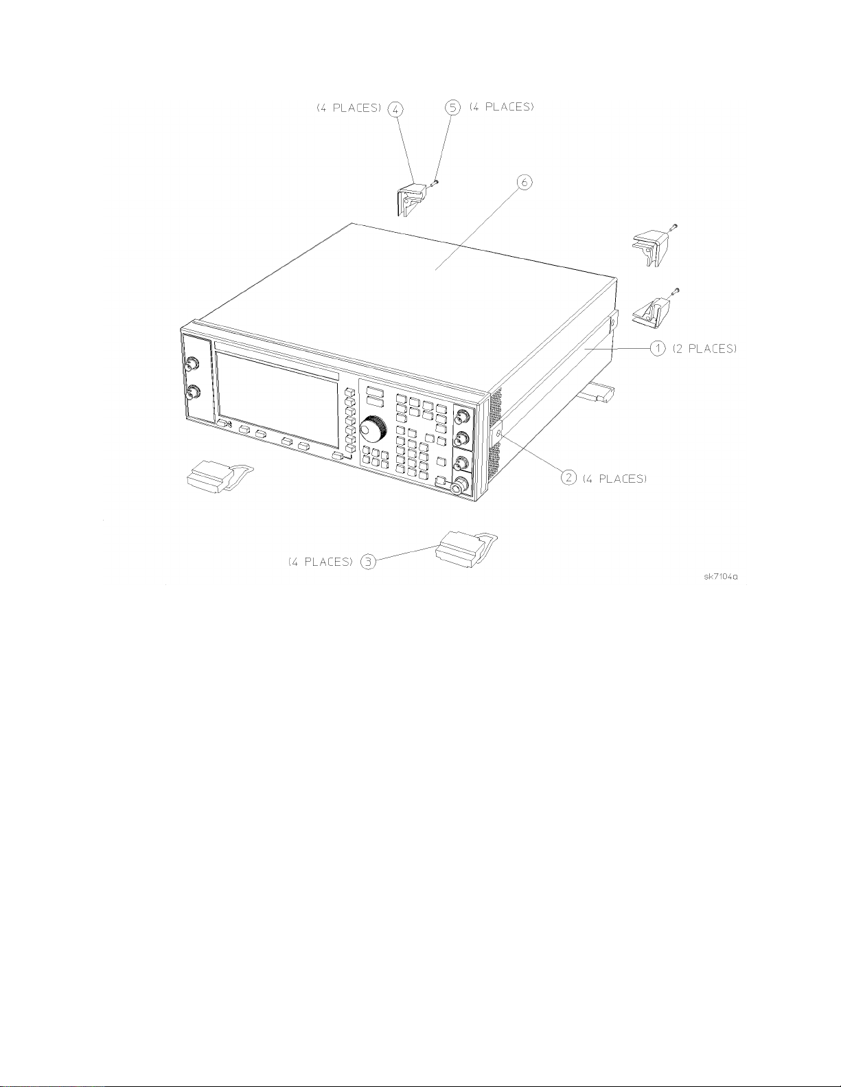
Figure 1
Installation Note E4400-90379 7
Page 8
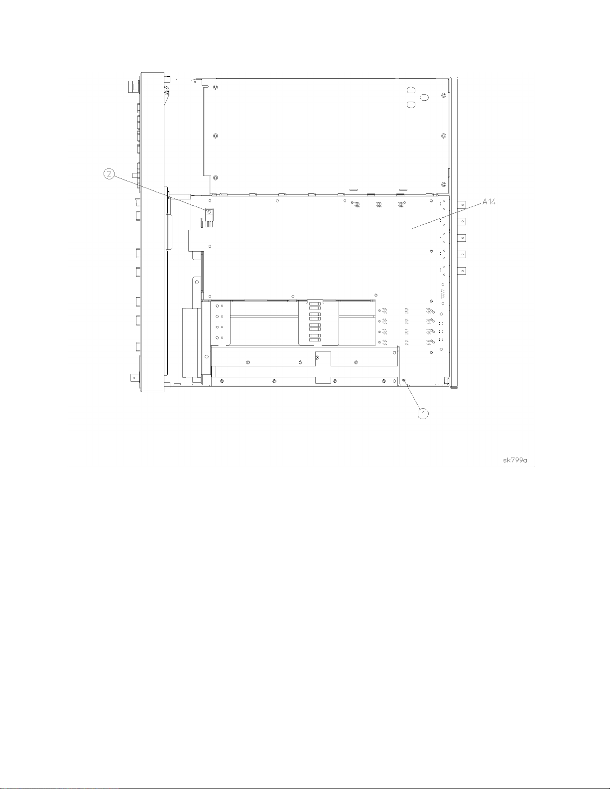
Figure 2
8 I nstal latio n Note E440 0-90379
Page 9

Figure 3
Installation Note E4400-90379 9
Page 10

Assemble Q501 to Front Inside of Chassis
1. Place Q501 nut plate with pem, part number E4400-00040, on the outside front of the chassis at slot
3 location. Place pem through slot 3. See Figure 4.
2. Place plate without pem, part number E4400-00041, inside the front chassis over slot 3 while
holding Q501 nut plate in position.
3. Place Q501 assembly, part number E4400-60221, on plate as shown in Figure 4.
NOTE Make sure the plates and harness are properly seated.
4. Secure Q501 assembly and plates to chassis with insulator bushing, part number 0340-1162, and
screw 3MMX10, part number 0515-0374. Torque screw to 9 in-lbs.
5. Now connect the Q501 assembly wiring harness connector to the motherboard as shown in Figure 5.
Make sure the harness is dressed and seated properly.
Measure Q501 Output Voltage on CPU/Motherboard A14
1. Take a digital voltmeter and measure test point TP 507 on the CPU/Motherboard A14. The voltage
at TP 507 should read +9 Vdc +- 4% to pass this test.
NOTE TP 507 is located on the top right, rear side of the motherboard, next to connector
J18.
2. If the voltage is correct at TP 507, turn off the power to the instrument. Unplug the signal generator
and turn it upside-down.
Bottom RF Cover Installation
1. Reinstall the instrument bottom cover with the 15 screws that secure it. Torque all T -10 Torx screws
to 9 in-lbs.
Verification, Turn on the Instrument
1. Plug in the instrument and press the power switch to turn on the signal generator to verify the
instrument.
2. Check the front panel display for text or characters. Also check the signal generator for error
messages. Let the instrument warm up for at least 5 minutes.
a. Press the front panel
b. Repeat the functionality check on page 5.
PRESET key to reset the RF signal generator.
10 Installation Note E4400-90379
Page 11
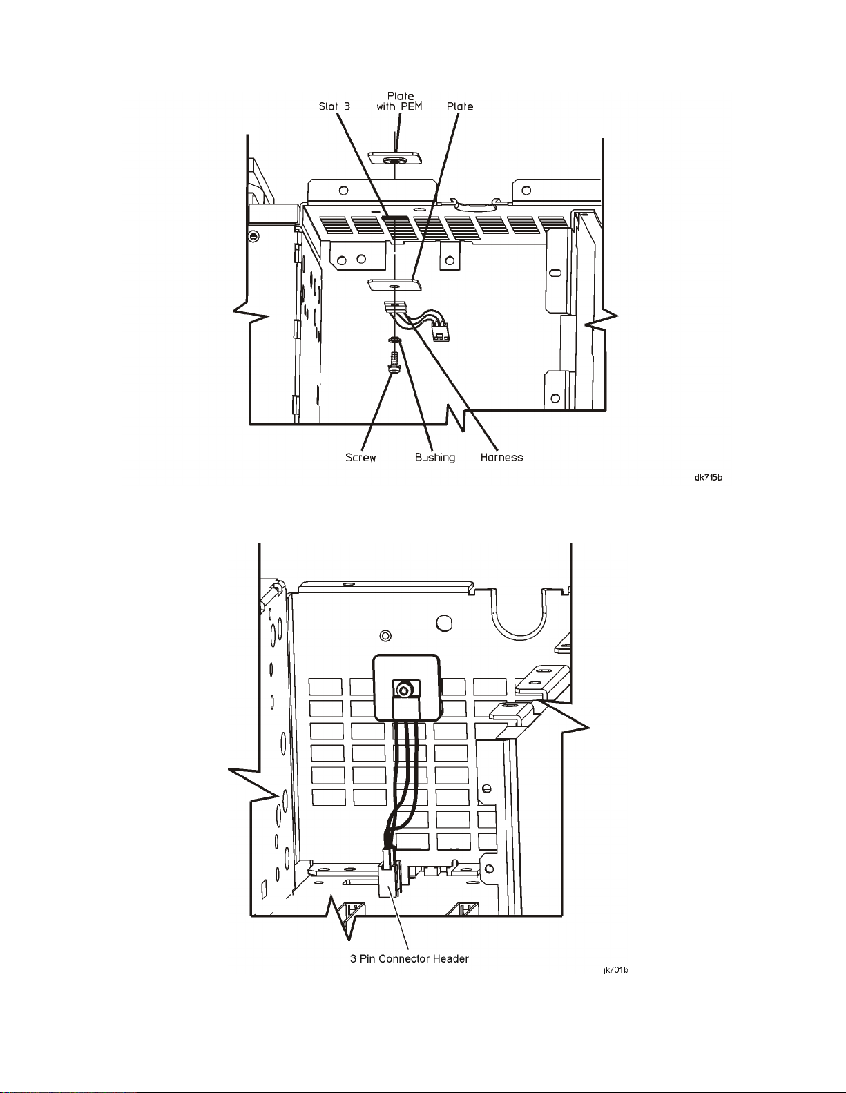
Figure 4
Figure 5
Installation Note E4400-90379 11
Page 12

Re-Assemble the Instrument
1. Turn the instrument off and unplug it.
2. Reinstall the instrument top cover with the 11 screws that secure it. Torque all T-10 Torque screws
to 9 in-lbs. Refer to Figure 1.
3. Reinstall the instrument’s external covers by reversing the removal procedure.
a. Torque the four rear feet screws to 21 in-lbs.
Torque the strap handle screws to 21 in-lbs.
12 Installation Note E4400-90379
 Loading...