

Page 1

User’s Guide
HP ESG and HP ESG-D Series Signal Generators
HP Part No. E4400-90142
Printed in USA
October 1998
Supersedes July 1998
© Copyright 1998 Hewlett-Packard Company
Page 2

ii
Page 3

Contents
1. Preparing for Use
Installing the Signal Generator. . . . . . . . . . . . . . . . . . . . . . . . . . . . . . . . . . . . . . . . . . . . . . . . .1-2
Verifying Signal Generator Operation . . . . . . . . . . . . . . . . . . . . . . . . . . . . . . . . . . . . . . . . . . .1-8
2. Using Functions
Setting Frequency and Power Levels . . . . . . . . . . . . . . . . . . . . . . . . . . . . . . . . . . . . . . . . . . . .2-2
Setting Up Internally Generated Amplitude Modulation . . . . . . . . . . . . . . . . . . . . . . . . . . . .2-5
Setting Up Internally Generated Frequency Modulation . . . . . . . . . . . . . . . . . . . . . . . . . . . .2-7
Creating a Step Sweep and a List Sweep . . . . . . . . . . . . . . . . . . . . . . . . . . . . . . . . . . . . . . . . .2-9
Saving and Recalling an Instrument State. . . . . . . . . . . . . . . . . . . . . . . . . . . . . . . . . . . . . . .2-12
Enabling Options . . . . . . . . . . . . . . . . . . . . . . . . . . . . . . . . . . . . . . . . . . . . . . . . . . . . . . . . . . .2-13
3. Troubleshooting
If You Encounter a Problem. . . . . . . . . . . . . . . . . . . . . . . . . . . . . . . . . . . . . . . . . . . . . . . . . . . .3-2
Error Messages. . . . . . . . . . . . . . . . . . . . . . . . . . . . . . . . . . . . . . . . . . . . . . . . . . . . . . . . . . . . . .3-6
Error Message Format. . . . . . . . . . . . . . . . . . . . . . . . . . . . . . . . . . . . . . . . . . . . . . . . . . . . . . . .3-7
Error Message Types . . . . . . . . . . . . . . . . . . . . . . . . . . . . . . . . . . . . . . . . . . . . . . . . . . . . . . . . .3-8
0: No Error. . . . . . . . . . . . . . . . . . . . . . . . . . . . . . . . . . . . . . . . . . . . . . . . . . . . . . . . . . . . . . . . .3-9
-499 to -400: Query Errors . . . . . . . . . . . . . . . . . . . . . . . . . . . . . . . . . . . . . . . . . . . . . . . . . . .3-10
-399 to -300: Device-Specific Errors . . . . . . . . . . . . . . . . . . . . . . . . . . . . . . . . . . . . . . . . . . . .3-11
-299 to -200: Execution Errors . . . . . . . . . . . . . . . . . . . . . . . . . . . . . . . . . . . . . . . . . . . . . . . .3-20
-199 to -100: Command Errors . . . . . . . . . . . . . . . . . . . . . . . . . . . . . . . . . . . . . . . . . . . . . . . .3-42
201 to 702: Device-Specific Errors . . . . . . . . . . . . . . . . . . . . . . . . . . . . . . . . . . . . . . . . . . . . .3-48
Returning Your Signal Generator to HP. . . . . . . . . . . . . . . . . . . . . . . . . . . . . . . . . . . . . . . . .3-61
HP Sales and Service Offices. . . . . . . . . . . . . . . . . . . . . . . . . . . . . . . . . . . . . . . . . . . . . . . . . .3-62
4. Front and Rear Panel
Front Panel Overview . . . . . . . . . . . . . . . . . . . . . . . . . . . . . . . . . . . . . . . . . . . . . . . . . . . . . . . .4-2
Display Annotation. . . . . . . . . . . . . . . . . . . . . . . . . . . . . . . . . . . . . . . . . . . . . . . . . . . . . . . . . . .4-8
Rear Panel Overview . . . . . . . . . . . . . . . . . . . . . . . . . . . . . . . . . . . . . . . . . . . . . . . . . . . . . . . .4-12
5. Hardkey and Softkey Reference
AM. . . . . . . . . . . . . . . . . . . . . . . . . . . . . . . . . . . . . . . . . . . . . . . . . . . . . . . . . . . . . . . . . . . . . . . .5-2
Ampl . . . . . . . . . . . . . . . . . . . . . . . . . . . . . . . . . . . . . . . . . . . . . . . . . . . . . . . . . . . . . . . . . . . . .5-16
Amplitude . . . . . . . . . . . . . . . . . . . . . . . . . . . . . . . . . . . . . . . . . . . . . . . . . . . . . . . . . . . . . . . . .5-23
Arrow Keys . . . . . . . . . . . . . . . . . . . . . . . . . . . . . . . . . . . . . . . . . . . . . . . . . . . . . . . . . . . . . . . .5-24
Display Contrast Keys . . . . . . . . . . . . . . . . . . . . . . . . . . . . . . . . . . . . . . . . . . . . . . . . . . . . . . .5-25
FM. . . . . . . . . . . . . . . . . . . . . . . . . . . . . . . . . . . . . . . . . . . . . . . . . . . . . . . . . . . . . . . . . . . . . . .5-26
Freq. . . . . . . . . . . . . . . . . . . . . . . . . . . . . . . . . . . . . . . . . . . . . . . . . . . . . . . . . . . . . . . . . . . . . .5-41
Frequency . . . . . . . . . . . . . . . . . . . . . . . . . . . . . . . . . . . . . . . . . . . . . . . . . . . . . . . . . . . . . . . . .5-46
Help. . . . . . . . . . . . . . . . . . . . . . . . . . . . . . . . . . . . . . . . . . . . . . . . . . . . . . . . . . . . . . . . . . . . . .5-47
Hold. . . . . . . . . . . . . . . . . . . . . . . . . . . . . . . . . . . . . . . . . . . . . . . . . . . . . . . . . . . . . . . . . . . . . .5-48
Incr Set . . . . . . . . . . . . . . . . . . . . . . . . . . . . . . . . . . . . . . . . . . . . . . . . . . . . . . . . . . . . . . . . . . .5-49
I/Q . . . . . . . . . . . . . . . . . . . . . . . . . . . . . . . . . . . . . . . . . . . . . . . . . . . . . . . . . . . . . . . . . . . . . . .5-50
LF Out. . . . . . . . . . . . . . . . . . . . . . . . . . . . . . . . . . . . . . . . . . . . . . . . . . . . . . . . . . . . . . . . . . . .5-61
Local . . . . . . . . . . . . . . . . . . . . . . . . . . . . . . . . . . . . . . . . . . . . . . . . . . . . . . . . . . . . . . . . . . . . .5-75
Mod On/Off . . . . . . . . . . . . . . . . . . . . . . . . . . . . . . . . . . . . . . . . . . . . . . . . . . . . . . . . . . . . . . . .5-76
Mode . . . . . . . . . . . . . . . . . . . . . . . . . . . . . . . . . . . . . . . . . . . . . . . . . . . . . . . . . . . . . . . . . . . . .5-77
iii
Page 4

Contents
Numeric Keypad . . . . . . . . . . . . . . . . . . . . . . . . . . . . . . . . . . . . . . . . . . . . . . . . . . . . . . . . . . . 5-78
Phase Modulation . . . . . . . . . . . . . . . . . . . . . . . . . . . . . . . . . . . . . . . . . . . . . . . . . . . . . . . . . . 5-79
Power Switch . . . . . . . . . . . . . . . . . . . . . . . . . . . . . . . . . . . . . . . . . . . . . . . . . . . . . . . . . . . . . .5-95
Preset . . . . . . . . . . . . . . . . . . . . . . . . . . . . . . . . . . . . . . . . . . . . . . . . . . . . . . . . . . . . . . . . . . . . 5-96
Pulse. . . . . . . . . . . . . . . . . . . . . . . . . . . . . . . . . . . . . . . . . . . . . . . . . . . . . . . . . . . . . . . . . . . . 5-105
Recall . . . . . . . . . . . . . . . . . . . . . . . . . . . . . . . . . . . . . . . . . . . . . . . . . . . . . . . . . . . . . . . . . . . 5-109
Return . . . . . . . . . . . . . . . . . . . . . . . . . . . . . . . . . . . . . . . . . . . . . . . . . . . . . . . . . . . . . . . . . . 5-112
RF On/Off. . . . . . . . . . . . . . . . . . . . . . . . . . . . . . . . . . . . . . . . . . . . . . . . . . . . . . . . . . . . . . . . 5-113
Save . . . . . . . . . . . . . . . . . . . . . . . . . . . . . . . . . . . . . . . . . . . . . . . . . . . . . . . . . . . . . . . . . . . .5-114
Sweep/List . . . . . . . . . . . . . . . . . . . . . . . . . . . . . . . . . . . . . . . . . . . . . . . . . . . . . . . . . . . . . . .5-119
Trigger . . . . . . . . . . . . . . . . . . . . . . . . . . . . . . . . . . . . . . . . . . . . . . . . . . . . . . . . . . . . . . . . . .5-135
Utility. . . . . . . . . . . . . . . . . . . . . . . . . . . . . . . . . . . . . . . . . . . . . . . . . . . . . . . . . . . . . . . . . . . 5-137
6. Options and Accessories
Signal Generator Options . . . . . . . . . . . . . . . . . . . . . . . . . . . . . . . . . . . . . . . . . . . . . . . . . . . . . 6-2
Signal Generator Accessories . . . . . . . . . . . . . . . . . . . . . . . . . . . . . . . . . . . . . . . . . . . . . . . . . . 6-6
7. Operation
8. Safety and Regulatory
Safety Notes. . . . . . . . . . . . . . . . . . . . . . . . . . . . . . . . . . . . . . . . . . . . . . . . . . . . . . . . . . . . . . . . 8-2
Instrument Markings . . . . . . . . . . . . . . . . . . . . . . . . . . . . . . . . . . . . . . . . . . . . . . . . . . . . . . . . 8-3
General Safety Considerations. . . . . . . . . . . . . . . . . . . . . . . . . . . . . . . . . . . . . . . . . . . . . . . . . 8-4
Statement of Compliance . . . . . . . . . . . . . . . . . . . . . . . . . . . . . . . . . . . . . . . . . . . . . . . . . . . . .8-5
Warranty . . . . . . . . . . . . . . . . . . . . . . . . . . . . . . . . . . . . . . . . . . . . . . . . . . . . . . . . . . . . . . . . . .8-6
Assistance . . . . . . . . . . . . . . . . . . . . . . . . . . . . . . . . . . . . . . . . . . . . . . . . . . . . . . . . . . . . . . . . . 8-7
Certification . . . . . . . . . . . . . . . . . . . . . . . . . . . . . . . . . . . . . . . . . . . . . . . . . . . . . . . . . . . . . . . . 8-8
Declaration of Conformity. . . . . . . . . . . . . . . . . . . . . . . . . . . . . . . . . . . . . . . . . . . . . . . . . . . . . 8-9
Compliance with German Noise Requirements. . . . . . . . . . . . . . . . . . . . . . . . . . . . . . . . . . .8-10
9. Specifications
Signal Generators Specifications . . . . . . . . . . . . . . . . . . . . . . . . . . . . . . . . . . . . . . . . . . . . . . . 9-2
iv
Page 5

HP ESG and HP ESG-D Series Signal Generators
1Preparing for Use
This chapter contains procedures that show you how to install your signal generator, and
how to perform a functional check to verify signal generator operation.
User’s Guide 1-1
Page 6

Preparing for Use HP ESG and HP ESG-D Series Signal Generators
Installing the Signal Generator
Installing the Signal Generator
This section contains procedures for properly installing your signal generator:
• checking the shipment
• installing front handles and rack flange kits
• meeting electrical and environmental requirements
• adjusting the display
• selecting the signal generator’s HP-IB address
• selecting the programming language
Checking the Shipment
1. Inspect the shipping container for damage.
Look for signs of damage such as a dented or torn shipping container, or cushioning
material that shows signs of unusual stress or compacting.
2. Carefully remove the contents from the shipping container and verify that your order is
complete. Refer to Table 1-1 and Table 1-2 for a list of items that are shipped standard
with the signal generator and for a list of options that you may also have ordered.
Table 1-1 Shipment Verification List
Part Number Item Description Option
Unique to Country AC Power Cable Standard
5063-9227 Front Handle Kit 1CN
5063-9214 Rack Flange Kit (without handles) 1CM
5063-9221 Rack Flange Kit (with handles) 1CP
E4400-90145 Manual Set for HP ESG-D Series Standard
E4400-90141 Manual Set for HP ESG Series Standard
E4400-90145 or
E4400 90141
E4400-90155 Service Guide 0BW, 0BX
E4400-90156 Component Level Information Guide 0BV, 0BX
Additional Manual Set OB1
1-2 User’s Guide
Page 7

HP ESG and HP ESG-D Series Signal Generators Preparing for Use
Installing the Signal Generator
The following table describes the localized versions of the manuals that you will receive if
you have ordered the options listed. In most cases, a subset of the user’s information from
the manual listed is localized. These options are available at no charge at the time of your
purchase of the signal generator. (Because the localization of these manuals is begun after
the English version is written, the localized manuals will become available over a period of
time. You may not receive all of the manuals listed.)
Table 1-2 Shipment Verification List for Localized Manuals
Part Number Item Description Language Option
E4400-90172
E4400-90180
E4400-90187
E4400-90194
E4400-90201
E4400-90173
E4400-90181
E4400-90188
E4400-90195
E4400-90202
E4400-90174
E4400-90182
E4400-90189
E4400-90196
E4400-90203
E4400-90212
E4400-90175
E4400-90183
E4400-90190
E4400-90197
E4400-90204
E4400-90210
E4400-90176
E4400-90179
E4400-90184
E4400-90191
E4400-90198
E4400-90205
E4400-90208
E4400-90209
E4400-90177
E4400-90185
E4400-90192
E4400-90199
E4400-90206
E4400-90178
E4400-90186
E4400-90193
E4400-90200
E4400-90207
E4400-90211
HP ESG and ESG-D User’s Guide
Real-Time I/Q Baseband Generator Guide
Dual Arbitrary Waveform Generator Guide
DECT Guide
GSM Guide
HP ESG and ESG-D User’s Guide
Real-Time I/Q Baseband Generator Guide
Dual Arbitrary Waveform Generator Guide
DECT Guide
GSM Guide
HP ESG and ESG-D User’s Guide
Real-Time I/Q Baseband Generator Guide
Dual Arbitrary Waveform Generator Guide
DECT Guide
GSM Guide
TETRA Guide
HP ESG and ESG-D User’s Guide
Real-Time I/Q Baseband Generator Guide
Dual Arbitrary Waveform Generator Guide
DECT Guide
GSM Guide
TETRA Guide
HP ESG and ESG-D User’s Guide
Bit Error Rate Test Guide
Real-Time I/Q Baseband Generator Guide
Dual Arbitrary Waveform Generator Guide
DECT Guide
PDC Guide
PHS Guide
GSM Guide
HP ESG and ESG-D User’s Guide
Real-Time I/Q Baseband Generator Guide
Dual Arbitrary Waveform Generator Guide
DECT Guide
GSM Guide
HP ESG and ESG-D User’s Guide
Real-Time I/Q Baseband Generator Guide
Dual Arbitrary Waveform Generator Guide
DECT Guide
GSM Guide
TETRA Guide
Chinese AB2
Chinese for Taiwan AB0
French ABF
German ABD
Japanese ABJ
Korean AB1
Spanish ABE
User’s Guide 1-3
Page 8

Preparing for Use HP ESG and HP ESG-D Series Signal Generators
Installing the Signal Generator
Installing Front Handles and Rack Mount Flanges
You can attach handles to the front of the signal generator to facilitate transportation of
the instrument. Handles are available in a kit which can be ordered when the signal
generator is purchased (Option 1CN), or at any time afterward. Assembly instructions are
included with the kit. The kit part number is listed in Table 1-3.
You can also rack mount the signal generator. Hardware is available in kits to install rack
mount flanges on the signal generator without or with handles. These kits can be ordered
when the signal generator is purchased (Options 1CM and 1CP), or at any time afterward.
Assembly instructions are included with the kits. The kit part numbers are listed in
Table 1-3.
Table 1-3 Front Handle and Rack Mount Flange Kits
Option Description HP Part Number
Option 1CN Front Handle Kit 5063-9227
Option 1CM Rack Mount Kit without Handles 5063-9214
Option 1CP Rack Mount Kit with Handles 5063-9221
Providing Adequate Ventilation
CAUTION Ventilation Requirements: When installing the product in a cabinet, the
convection into and out of the product must not be restricted. The ambient
temperature (outside the cabinet) must be less than the maximum operating
temperature of the product by 4 °C for every 100 watts dissipated in the
cabinet. If the total power dissipated in the cabinet is greater than 800 watts,
then forced convection must be used.
Cooling holes are located on the sides and bottom of the instrument cover and the rear
panel of the instrument. Do not allow these holes to be obstructed as they allow air flow
through the signal generator.
1-4 User’s Guide
Page 9

HP ESG and HP ESG-D Series Signal Generators Preparing for Use
Installing the Signal Generator
Meeting Electrical and Environmental Requirements
Line Settings
CAUTION This product has an autoranging line voltage input. Be sure that the supply
voltage is within the specified range.
The available AC power source must meet the following requirements:
Voltage:
• 100/115 volts nominal (90-132 volt range)
• 230/240 volts nominal (198-254 volt range)
Frequency:
• for 100/115 volts: 50/60/400 Hz nominal
• for 230/240 volts: 50/60 Hz nominal
Power:
• 200 watts maximum
Verify that the power cable is not damaged and that the power source socket outlet
provides a protective earth contact.
WARNING This is a Safety Class 1 Product (provided with a protective earthing
ground incorporated in the power cord). The mains plug shall only
be inserted in a socket outlet provided with a protective earth
contact. Any interruption of the protective conductor inside or
outside of the product is likely to make the product dangerous.
Intentional interruption is prohibited.
CAUTION Always use the three-prong AC power cord supplied with this product.
F ailure to ensure adequate earth grounding by not using this cord ma y cause
product damage.
Environment
This product is designed for use in the following environmental conditions:
• indoor use
• < 15,000 feet (4,572 meters) altitude
• 0 to 55 °C temperature, unless specified differently
• maximum relative humidity 80% for temperatures up to 31 °C, decreasing linearly to
50% relative humidity at 40 °C
CAUTION This product is designed for use in INSTALLATION CATEGORY II and
POLLUTION DEGREE 2, per IEC 1010 and 664 respectively.
User’s Guide 1-5
Page 10

Preparing for Use HP ESG and HP ESG-D Series Signal Generators
Installing the Signal Generator
WARNING If this product is not used as specified, the protection provided by
the equipment could be impaired. This product must be used in a
normal condition only (in which all means for protection are intact).
Cleaning the Signal Generator
Clean the instrument cabinet using a damp cloth only.
Adjusting the Display Contrast
You can adjust the contrast of the display by pressing the decrease contrast key or
the increase contrast key . These keys are located on the front panel below the
display.
Pressing the decrease contrast key and holding it down causes the display background to
gradually darken in comparison to the text on the display. The minimum contrast setting
is not a completely black display. Some contrast between the background and the text will
still be visible.
Pressing the increase contrast key and holding it down causes the display background to
gradually brighten in comparison to the text on the display. If the background does not
appear to change, it is probably set to the maximum contrast.
Selecting Inverse Video
The normal display mode for the signal generator is dark text on a light background. To
change to inverse video (light text on a dark background), press
Inverse Video Off On to On. Inverse video is a persistent state; it is not affected by an
Utility, Display and set
instrument preset or by a power cycle.
Adjusting the Screen Saver
You can increase the life expectancy of the signal generator’s display light by turning on
the screen saver. Leaving the display lit for long periods of time or turning the display on
and off frequently decreases the life of the bulb. With the screen saver on, the display light
is turned off after a defined period of time with no input to the front panel. The display
light turns on again when any front panel key is pressed or when a remote command is
sent.
The screen saver is set to off at the factory. You can turn it on by pressing
Screen Saver Off On. Each time you press Screen Saver Off On the selection toggles between Off
and On.
You can adjust the screen saver mode to turn the light on and off or to turn both the light
and text on and off. Press Utility, Display, Screen Saver Mode. You can toggle between Light Only
and Light & Text. Setting the mode to Light Only turns the display light off but leaves the text
visible at a low intensity. To prevent the text from burning the display if you are leaving
the display unchanged for long periods of time, set the mode to
Light & Text. This mode turns
off the display light and the text.
Utility, Display,
1-6 User’s Guide
Page 11

HP ESG and HP ESG-D Series Signal Generators Preparing for Use
Installing the Signal Generator
The screen saver delay is set to 1 hour at the factory. You can view and change the delay by
pressing
Screen Saver Delay in the same menu. The current screen saver delay is displayed in
the softkey label and also in the active entry area. To change the delay, enter a new value
using the numeric keypad and then press
Enter, or rotate the front panel knob. The
acceptable range of delay values is 1 through 12 hours in 1 hour increments.
The screen saver settings do not change when Preset is pressed, nor when power to the
instrument is cycled.
Selecting the Signal Generator’s HP-IB Address
The signal generator’s HP-IB address is set to 19 at the factory. You can view and change
the address by pressing
displayed in the softkey label and also in the active entry area. To change the address,
enter a new value using the numeric keypad and then press
knob. The acceptable range of addresses is 0 through 30.
The HP-IB address is a persistent state; it is not affected by an instrument preset or by a
power cycle.
Utility, HP-IB/RS-232, HP-IB Address. The current HP-IB address is
Enter, or rotate the front panel
Selecting the Signal Generator’s Programming Language
The default programming language for the signal generator is Standard Commands for
Programmable Instruments (SCPI). You can change this language selection by pressing
Utility, HP-IB/RS-232, Remote Language. You can change this language selection by pressing
Utility, HP-IB/RS-232, Remote Language. The Remote Language menu allows you to select
between HP 8656/57-compatible language, HP 8648-compatible language, and SCPI
language. If you have an HP ESG-D Series Option UN8, the Remote Language menu
allows you to select between HP 8656/57-compatible language, HP 8657D language
(NADC digital modulation capability), HP 8657D language (PDC digital modulation
capability), and HP 8657J (PHS digital modulation capability). Press the softkey for the
selection that you desire.
You can also change the language selection by sending the appropriate command over
HP-IB. Refer to the programming guide for instructions for changing the language over
HP-IB.
You can set the signal generator to default to a selected language as a persistent state
(remains unchanged after an instrument preset or power cycle). Press
Power On/Preset, Preset Language. The Preset Language menu allow you to select between
SCPI, the HP 8656/57-compatible programming languages, and HP 8648-compatible
language. Press the softkey for the selection that you desire.
Utility,
User’s Guide 1-7
Page 12

Preparing for Use HP ESG and HP ESG-D Series Signal Generators
Verifying Signal Generator Operation
Verifying Signal Generator Operation
The operator’s check is appropriate as a daily functional check by users, or whenever the
integrity of the signal generator is in question. Use the operator’s check to verify proper
operation of the signal generator. The operator’s check does not ensure performance to
specifications. To verify specifications, refer to the calibration guide.
Operator’s Check
Perform the following tasks in order:
Power On the Signal Generator and Check for Error Messages
This procedure verifies that the signal generator powers up and that the internal
instrument check identifies no errors.
1. Turn power on to the signal generator by pressing the power switch. The green LED
will light. Let the instrument warm up for one hour.
2. Cycle the power to the signal generator. The green LED should again be lit and the
instrument will perform a check.
3. When the display is lit, check to see if the
4. If the
Utility, Error Info. The first error message in the queue will be shown in the text area of the
ERR annunciator is turned on, review the error messages in the queue by pressing
ERR annunciator is turned on.
display. Refer to Chapter 3, “Troubleshooting,” for information about the error message.
If there is more than one error message (each message will be designated as 1 of n),
press the
5. When you have resolved all of the error messages, press
View Next Error Message softkey until you have seen all of the messages.
Clear Error Queue(s) to delete the
messages. Then restart this procedure at step two.
Note: For instruments with Option 1E5, ERROR 514, Reference Oven Cold will occur
whenever the signal generator is first connected to AC line power. The
OVEN COLD
annunciator and the ERR annunciator will both turn on. The OVEN COLD annunciator
will automatically clear after approximately 5 minutes. The error queue cannot be
cleared, however, until the
OVEN COLD annunciator has turned off.
Verify Maximum Specified Power is Available at the Maximum Frequency
This procedure verifies that there are no unleveled power indications or error messages at
the maximum specified frequency and power level.
1. Calibrate the power meter with the power sensor. (Refer to the power meter’s manual
for assistance.)
2. Connect the power sensor to the signal generator’s RF OUTPUT connector as shown in
Figure 1-1.
1-8 User’s Guide
Page 13

HP ESG and HP ESG-D Series Signal Generators Preparing for Use
Verifying Signal Generator Operation
Figure 1-1 Operator’s Check Equipment Setup
3. Preset the signal generator to the factory-defined conditions:
a. Press
b. Press the front panel
Utility, Power On/Preset and toggle Preset until Normal is highlighted.
Preset key.
4. Set the signal generator to its maximum specified frequency:
a. Press
Frequency.
b. Use the numeric keypad to enter the signal generator’s maximum specified
frequency as shown in Table 1-4.
c. Terminate your entry by pressing the
GHz softkey.
5. Set the signal generator to its maximum specified power level:
a. Press
Amplitude.
b. Use the numeric keypad to enter the signal generator’s maximum specified power
level as shown in Table 1-4.
c. Terminate your entry by pressing the
6. Toggle the front panel
The display
RF ON annunciator will turn on.
RF On/Off key to turn on RF power to the RF OUTPUT connector.
dBm softkey.
7. Verify that the power meter reads the maximum specified output power including the
power level accuracy limits.
8. Check to see if the
UNLEVEL or ERR display annunciators have turned on. If these
annunciators are on, refer to the service guide for troubleshooting information.
User’s Guide 1-9
Page 14

Preparing for Use HP ESG and HP ESG-D Series Signal Generators
Verifying Signal Generator Operation
Table 1-4 Frequency and Power Level Limits
Instrument
Model
HP E4400B
HP E4430B
HP E4420B
HP E4431B
HP E4421B
HP E4432B
HP E4422B
HP E4433B
Maximum
Specified
Frequency
1 GHz +13 dBm ±0.7 dB
2 GHz +10 dBm ±0.7 dB
3 GHz +10 dBm ±1.0 dB
4 GHz +7 dBm ±1.0 dB
Maximum
Specified
Power
Power Level
Accuracy
Limits
1. The values provided are confidence levels only; they are
not specifications.
1
1-10 User’s Guide
Page 15

HP ESG and HP ESG-D Series Signal Generators
2Using Functions
This chapter contains procedures that show you how to use some of the major functions of
your signal generator including setting frequency and power levels, setting up
modulations, creating step and list sweeps, saving and recalling instrument states, and
enabling options.
User’s Guide 2-1
Page 16

Using Functions HP ESG and HP ESG-D Series Signal Generators
Setting Frequency and Power Levels
Setting Frequency and Power Levels
Using these procedures, you will learn how to:
• set the RF frequency
• set a frequency reference and a frequency offset
• set the RF output power level
• set an amplitude reference and an amplitude offset
To Set the RF Frequency
1. Turn on power to the signal generator: press the power switch, , so that the green
LED is on. The signal generator will perform an internal check.
2. Press the green Preset key. The signal generator will return to a set of factory-defined
conditions.
NOTE You can change the preset conditions to a user-defined instrument state.
However, for the purpose of these examples, use the factory-defined preset
state (the Preset Normal User softkey in the Utility menu must be set to Normal).
3. Observe the frequency area of the display (in the upper left-hand corner). It should
display the maximum specified frequency of your signal generator.
4. The signal generator is set to output an RF signal, however the
set to
Notice that the display annunciator changes from
On before the RF signal is available at the RF OUTPUT connector. Press RF On/Off.
RF OFF to RF ON. The maximum
RF On/Off key must be
specified frequency is now being output at the RF OUTPUT connector.
5. Change the frequency to 700 MHz by pressing Frequency. The current RF frequency is
now displayed in the active entry area of the display. Using the numeric keypad, enter
700 and then press the MHz terminator softkey. The new 700 MHz RF frequency is now
displayed in the frequency area of the display and also in the active entry area.
6. Frequency is still the active function until you press another front panel function key.
Change the frequency again by pressing the up arrow key once. Each press of the up
arrow key increases the frequency by the increment value last set with the
Incr Set key.
The increment value is displayed in the active entry area.
The down arrow works like the up arrow. Practice stepping the frequency up and down
in 1 MHz increments. Use the
Incr Set key to change the increment value to 1 MHz, if
necessary.
7. Y ou can also adjust the RF frequency using the front panel knob. As long as frequency is
the active function (the frequency is displayed in the active entry area), the front panel
knob will increase and decrease the RF frequency. Use the front panel knob to adjust
the frequency back to 700 MHz.
2-2 User’s Guide
Page 17

HP ESG and HP ESG-D Series Signal Generators Using Functions
Setting Frequency and Power Levels
To Set a Frequency Reference and a Frequency Offset
The following procedure sets the RF output frequency as a reference frequency to which all
other frequency parameters are relative. The frequency initially shown on the display will
be 0 Hz (the frequency output by the hardware minus the reference frequency.) Although
the display changes, the frequency output does not change. Any subsequent frequency
changes are shown as incremental or decremental to 0 Hz.
1. Press
Preset to return the signal generator to the factory-defined instrument state.
2. Set the RF frequency to 700 MHz.
3. Turn on frequency reference mode and set the current output frequency (700 MHz) as
the reference value. Press
Freq, Freq Ref Set. The frequency displayed is 0 Hz (the
frequency output by the hardware, 700 MHz, minus the reference value, 700 MHz).
Notice that the
4. Set the
RF OFF to RF ON. The RF frequency at the RF OUTPUT connector is 700 MHz.
RF On/Off key to On. Notice that the display annunciator has changed from
REF indicator is turned on and the Freq Ref softkey has toggled to On.
5. Increment the output frequency by 1 MHz. Press the up arrow key. The frequency
display changes to show 1 MHz (the frequency output by the hardware,
700 MHz + 1 MHz, minus the reference frequency, 700 MHz) and the output frequency
changes to 701 MHz.
6. Enter a 1 MHz offset. Press the
keypad and pressing the
MHz terminator softkey. The frequency display shows 2 MHz
Freq Offset softkey and enter 1 MHz using the numeric
(the frequency output by the hardware, 701 MHz, minus the reference frequency,
700 MHz, plus the offset, 1 MHz.) Notice that the
OFFSET indicator is turned on. The
frequency at the RF OUTPUT connector is still 701 MHz.
To Set the RF Output Power Level
1. Press Preset to return the signal generator to the factory-defined instrument state.
2. Observe the amplitude area of the display (in the upper middle of the display). It should
display −135 dBm. This is the normal preset RF output power level.
3. The signal generator is set to output an RF signal, however the
set to
Notice that the display annunciator changes from
On before the RF signal is available at the RF OUTPUT connector. Press RF On/Off.
RF OFF to RF ON. The RF signal is
RF On/Off key must be
now being output at a −135 dBm level at the RF OUTPUT connector.
4. Change the power level to −20 dBm. Press Amplitude. The current power level is now
displayed in the active entry area of the display. Using the numeric keypad and the key,
enter
−20 and then press the dBm softkey. The new −20 dBm RF output power is now
displayed in the amplitude area of the display and also in the active entry area.
5. Amplitude is still the active function until you press another front panel function key.
You can also change the amplitude using the up and down arrow keys and the front
panel knob. Practice changing the amplitude using these methods also.
User’s Guide 2-3
Page 18

Using Functions HP ESG and HP ESG-D Series Signal Generators
Setting Frequency and Power Levels
To Set an Amplitude Reference and an Amplitude Offset
The following procedure sets the RF output power as an amplitude reference to which all
other amplitude parameters are relative. The amplitude initially shown on the display will
be 0 dB (the power output by the hardware minus the reference power). Although the
display changes, the output power does not change. Any subsequent power changes are
shown as incremental or decremental to 0 dB.
1. Press
Preset to return the signal generator to the factory-defined instrument state.
2. Set the RF output power to −20 dBm.
3. Turn on amplitude reference mode and set the current output power (−20 dBm) as the
reference value. Press
Ampl, More (1 of 2), Ampl Ref Set. The amplitude displayed is 0 dB
(the power output by the hardware, −20 dBm; minus the reference value, −20 dBm.)
Notice that the
4. Set the
RF OFF to RF ON. The power at the RF OUTPUT connector is −20 dBm.
RF On/Off key to On. Notice that the display annunciator has changed from
REF indicator is turned on and the Ampl Ref softkey has toggled to On.
5. Use the up arrow key to increase the output power by 10 dB. The amplitude display
changes to show 10 dB (the power output by the hardware, −20 dBm; +10 dBm; minus
the reference power, −20 dBm) and the output power changes to −10 dBm.
6. Enter a 10 dB offset. Press the Ampl Offset softkey and enter 10 dB using the numeric
keypad. The amplitude display shows 20 dB (the power output by the hardware,
−10 dBm; minus the reference power, −20 dBm; plus the offset, 10 dB). Notice that the
OFFS indicator is turned on. The power at the RF OUTPUT connector is still −10 dBm.
2-4 User’s Guide
Page 19

HP ESG and HP ESG-D Series Signal Generators Using Functions
Setting Up Internally Generated Amplitude Modulation
Setting Up Internally Generated Amplitude
Modulation
Using this procedure, you will learn how to generate an amplitude-modulated signal with
the following characteristics:
• carrier frequency set to 1340 kHz
• power level set to 0 dBm
• AM depth set to 90%
• AM rate set to 10 kHz
Setting the Carrier Frequency
1. Preset the signal generator to the factory-defined instrument state.
2. Press the front panel
normal preset value for frequency is displayed in the active entry area.
3. Enter 1340 kHz using the numeric keypad and pressing the kHz terminator softkey. The
new carrier frequency is shown in the frequency area of the display. You should see
1.340 000 00 MHz.
Frequency key. Frequency becomes the active function and the
Setting the Power Level
1. Press the front panel Amplitude key. Amplitude becomes the active function and the
normal preset value for amplitude is displayed in the active entry area.
2. Enter 0 dBm using the numeric keypad and pressing the dBm terminator softkey. The
new power level is shown in the amplitude area of the display. You should see
0.00 dBm.
Setting the AM Depth
1. Press the front panel AM key. The first level menu of softkeys is displayed.
2. Press the
value for AM depth is displayed in the active entry area.
3. Enter 90% using the numeric keypad and pressing the % terminator softkey. The new
AM depth is displayed below the
line of the softkey.
AM Depth softkey . AM depth becomes the active function and the normal preset
AM Depth softkey. You should see 90.0 % in the second
Setting the AM Rate
1. In the same AM menu, press the AM Rate softkey. AM rate becomes the active function
and the normal preset value for AM rate is displayed in the active entry area.
User’s Guide 2-5
Page 20

Using Functions HP ESG and HP ESG-D Series Signal Generators
Setting Up Internally Generated Amplitude Modulation
2. Enter 10 kHz using the numeric keypad and pressing the kHz terminator softkey. The
new AM rate is displayed below the
AM Rate softkey. You should see 10.0000 kHz in the
second line of the softkey.
Turning On Amplitude Modulation
The signal generator is now configured to output a 0 dBm, amplitude-modulated carrier at
1340 kHz with the AM depth set to 90% and the AM rate set to 10 kHz. The shape of the
waveform is a sinewave (notice that sine is the default for the
these remaining steps to output the amplitude-modulated signal.
AM Waveform softkey). Follow
1. In the same AM menu, press the
also, that the
AM display annunciator is turned on indicating that you have enabled
AM Off On softkey. AM toggles from Off to On. Notice,
amplitude modulation.
2. Press the front panel RF On/Off key to toggle RF on. Notice that the display annunciator
changes from
RF OFF to RF ON. The modulated signal is now available at the RF
OUTPUT connector.
2-6 User’s Guide
Page 21

HP ESG and HP ESG-D Series Signal Generators Using Functions
Setting Up Internally Generated Frequency Modulation
Setting Up Internally Generated Frequency
Modulation
Using this procedure you will configure the signal generator to output a
frequency-modulated signal with the following characteristics:
• carrier frequency set to 104.9 MHz
• power level set to 0 dBm
• FM deviation set to 75 kHz
• FM rate set to 10 kHz
Setting the Carrier Frequency
1. Preset the signal generator to the factory-defined instrument state.
2. Press the front panel
normal preset value for frequency is displayed in the active entry area.
3. Enter 104.9 MHz using the numeric keypad and pressing the MHz terminator softkey.
The new carrier frequency is shown in the frequency area of the display. You should see
104.900 000 00 MHz.
Frequency key. Frequency becomes the active function and the
Setting the Power Level
1. Press the front panel Amplitude key. Amplitude becomes the active function and the
normal preset value for amplitude is displayed in the active entry area.
2. Enter 0 dBm using the numeric keypad and pressing the dBm terminator softkey. The
new power level is shown in the amplitude area of the display. You should see
0.00 dBm.
Setting the FM Deviation
1. Press the front panel FM/ΦM key. The first level menu of FM softkeys is displayed.
2. Press the
preset value for FM deviation is displayed in the active entry area.
3. Enter 75 kHz using the numeric keypad and pressing the kHz terminator softkey. The
new FM deviation is displayed below the
second line of the softkey.
FM Dev softkey. FM deviation becomes the active function and the normal
FM Dev softkey . You should see 75.0000 kHz in the
Setting the FM Rate
1. In the same FM menu, press the FM Rate softkey. FM rate becomes the active function
and the normal preset value for FM rate is displayed in the active entry area.
User’s Guide 2-7
Page 22

Using Functions HP ESG and HP ESG-D Series Signal Generators
Setting Up Internally Generated Frequency Modulation
2. Enter 10 kHz using the numeric keypad and pressing the kHz terminator softkey. The
new FM rate is displayed below the
FM Rate softkey. You should see 10.0000 kHz in the
second line of the softkey.
Turning On Frequency Modulation
The signal generator is now configured to output a 0 dBm, frequency-modulated carrier at
104.9 MHz with the FM deviation set to 75 kHz and the FM rate set to 10 kHz. The shape
of the waveform is a sinewave. (Notice that sine is the default for the
Press
More (1 of 2) to see the softkey.) Follow these remaining steps to output the
frequency-modulated signal.
FM Waveform softkey.
1. In the same FM menu, press the
also, that the
FM display annunciator is turned on indicating that you have enabled
FM Off On softkey. FM toggles from Off to On. Notice,
frequency modulation.
2. Press the front panel RF On/Off key to toggle RF on. Notice that the display annunciator
changes from
RF OFF to RF ON. The modulated signal is now available at the RF
OUTPUT connector.
2-8 User’s Guide
Page 23

HP ESG and HP ESG-D Series Signal Generators Using Functions
Creating a Step Sweep and a List Sweep
Creating a Step Sweep and a List Sweep
Using this procedure, you will learn two ways to set up the signal generator to sweep a
defined set of points. You will create a step sweep and then you will use these points as the
basis for a new list sweep.
In the first procedure, you will create a step sweep with the following ten, equally spaced
points:
• frequency range from 525 MHz to 600 MHz
• power level from −20 dBm to 0 dBm
• dwell time 500 ms at each point
In the second procedure, you will take the step sweep points and edit several points to
change the sweep information.
Configuring a Step Sweep
1. Preset the signal generator to the factory-defined instrument state.
2. Press the front panel
the
Sweep Type List Step softkey to Step.
3. Press the
Configure Step Sweep softkey. Another menu is displayed with softkeys that you
Sweep/List key. The first level of sweep softkeys is displayed. Toggle
will use to create the sweep points.
4. Change the start frequency of the step sweep. Press the Freq Start softkey. Enter
525 MHz using the numeric keypad and pressing the
5. Change the stop frequency of the step sweep. Press the
using the numeric keypad and pressing the
MHz terminator softkey.
6. Set the power level for the start of the step sweep. Press the
−20 dBm using the numeric keypad and pressing the
7. Set the power level for the end of the step sweep. Press the
0 dBm using the numeric keypad and pressing the
8. Set the number of sweep points. Press the
# Points softkey. Enter 10 by rotating the front
MHz terminator softkey.
Freq Stop softkey . Enter 600 MHz
Ampl Start softkey. Enter
dBm terminator softkey.
Ampl Stop softkey. Enter
dBm terminator softkey.
panel knob until the number 10 is displayed.
9. Set the dwell time at each point. Press the Step Dwell softkey. Enter 500 ms using the
numeric keypad and pressing the
msec terminator softkey.
Turning On Continuous Step Sweep
1. Press Return to move up one menu level.
2. Press the
either the frequency, amplitude, or frequency and amplitude data. Press the
softkey. Selecting this softkey returns you to the previous menu and turns the sweep
function on.
User’s Guide 2-9
Sweep softkey. Another menu is displayed showing you choices for sweeping
Freq&Ampl
Page 24

Using Functions HP ESG and HP ESG-D Series Signal Generators
Creating a Step Sweep and a List Sweep
3. Press the Sweep Repeat Single Cont softkey to toggle from Single to Cont. Notice that the
SWEEP display annunciator is turned on indicating that the signal generator is
sweeping.
4. Press the front panel RF On/Off key to toggle RF on. Notice that the display annunciator
changes from
RF OFF to RF ON. The swept RF signal is now available at the RF
OUTPUT connector.
Configuring a List Sweep Using Step Sweep Data
1. Press the Sweep Type List Step softkey to toggle from Step to List.
2. Press the
Configure List Sweep softkey. Another menu is displayed with softkeys that you
will use to create the sweep points. Notice that the display shows the current list data.
(When no list has been previously created, the default is one point set to the signal
generator’s maximum frequency, −135 dBm, with a dwell time of 2 ms.)
3. Press
More (1 of 2), Load List From Step Sweep, Confirm Load From Step Sweep. The points you
defined in the step sweep are automatically loaded into the list.
Editing List Sweep Points
1. Change the dwell time for point 1 to 100 ms. Press the right arrow key twice until the
dwell time is highlighted. Press
the active function. Enter 100 ms using the numeric keypad and pressing the
terminator softkey. Notice that the next item in the table (in this case, the frequency
value for point 2) becomes highlighted after pressing the terminator softkey.
2. Change the frequency for point 4 to 560 MHz. Press the down arrow key two times until
the frequency is highlighted. Press the
becomes the active function. Enter 560 MHz using the numeric keypad and pressing
the
MHz terminator softkey.
3. Add a new point between points 7 and 8. Press the down arrow until any column in the
point 8 row is highlighted. Press the Insert Row softkey . A copy of point 8 has been placed
between points 7 and 8, creating a new point 8, and renumbering the successive points.
More (2 of 2), Edit Item. The dwell time for point 1 becomes
msec
Edit Item softkey. The frequency for point 4
4. Create a new point between points 10 and 11. Use the arrow keys to highlight the
frequency for point 11. Press the
keypad and pressing the
MHz terminator softkey. Notice that a new frequency item is
Edit Item softkey. Enter 700 MHz using the numeric
placed at point 11 and the frequency item previously occupying that position has shifted
down to point 12. The power and dwell time items do not shift down.
NOTE An informational ERR annunciator is turned on at this time indicating that
the frequency and power lists are of unequal size. You will correct that
problem in the following steps. The annunciator will not turn off until you
clear the error queue in the Utility menu.
The power for point 11 should now be highlighted. Press the
1 dBm using the numeric keypad and pressing the
dBm terminator softkey. A new power
Edit Item softkey and enter
item is placed at point 11 and the power item previously occupying that position has
shifted down to point 12.
2-10 User’s Guide
Page 25

HP ESG and HP ESG-D Series Signal Generators Using Functions
Creating a Step Sweep and a List Sweep
The dwell time for point 11 should now be highlighted. Press the Edit Item softkey. The
dwell time from the previous point 11 has been copied into the new point 11. A new
dwell time item is placed at point 11 and the dwell time item previously occupying that
position has shifted down to point 12.
Turning On List Sweep for a Single Sweep
1. Press Return to move up one menu level.
2. Notice that the
Sweep softkey is still set to sweep both frequency and amplitude data.
You do not need to change it.
3. Press the Sweep Repeat Single Cont softkey to toggle from Cont to Single. Notice that the
SWEEP display annunciator is turned off. The sweep will not occur until it is triggered.
4. Press
that the
5. Change the sweep trigger to occur when you press the front panel
More (1 of 2), Sweep Trigger. Another menu is displayed showing you choices for triggering
a sweep. Press the
6. Press
Single Sweep. The signal generator will sweep the points in your list once. Notice
SWEEP display annunciator is turned on during the sweep.
Trigger key. Press
Trigger Key softkey.
More (2 of 2), Single Sweep to arm the sweep. Notice that the ARMED display
annunciator has turned on.
7. Press the front panel Trigger key. The signal generator will sweep the points in your list
once and the
SWEEP display annunciator is turned on during the sweep.
User’s Guide 2-11
Page 26

Using Functions HP ESG and HP ESG-D Series Signal Generators
Saving and Recalling an Instrument State
Saving and Recalling an Instrument State
Using this procedure, you will learn how to save instrument settings to a memory register
and to recall the settings.
1. Preset the signal generator to the factory-defined instrument state.
2. Set up the signal generator with the following changes:
a. Set the frequency to 800 MHz.
b. Set the amplitude to 0 dBm.
c. Enable amplitude modulation (
AM display annunciator is on).
3. Save this instrument state in the signal generator memory in sequence 1, memory
register 01. Press the front panel Save key and then press the Select Seq softkey. The
sequence number becomes the active function. The signal generator will display the last
sequence that you have used. Set the sequence to 1 using the arrow keys.
Press the
Select Reg softkey. The register number in sequence 1 becomes the active
function. The signal generator will either display the last register used [accompanied by
the text:
the text:
4. Press the
(in use)] or , if no registers are in use , will display register 00 [accompanied by
(available)]. Use the arrow keys to select register 01.
Save Seq[1] Reg[01] softkey. The current instrument settings including the
frequency, amplitude, and modulation changes you made have been stored in signal
generator memory.
5. Preset the signal generator to the factory-defined instrument state.
6. Recall your instrument state. Press the front panel Recall key. Notice that the Select Seq
softkey shows sequence 1. (This is the last sequence that you have used.) You do not
need to change the sequence. Press
RECALL Reg. The register to be recalled in sequence 1
becomes the active function. Press the up arrow key once to select register 1. Notice
that your stored instrument settings have been immediately recalled.
2-12 User’s Guide
Page 27
HP ESG and HP ESG-D Series Signal Generators Using Functions
Enabling Options
Enabling Options
The HP ESG and ESG-D Series Signal Generators are a highly flexible platform of
instruments that you can retrofit after purchase to add many new capabilities. Some new
optional features are implemented in hardware that you must install. Some options are
implemented in software but require the presence of optional hardware in the instrument.
This example shows you how to enable both hardware and software options.
Enabling a Hardware Option
1. When you purchase a new hardware option for your signal generator, the hardware and
instructions for installing the hardware will be included in a kit that you receive. Follow
the installation instructions to retrofit your signal generator with the new hardware.
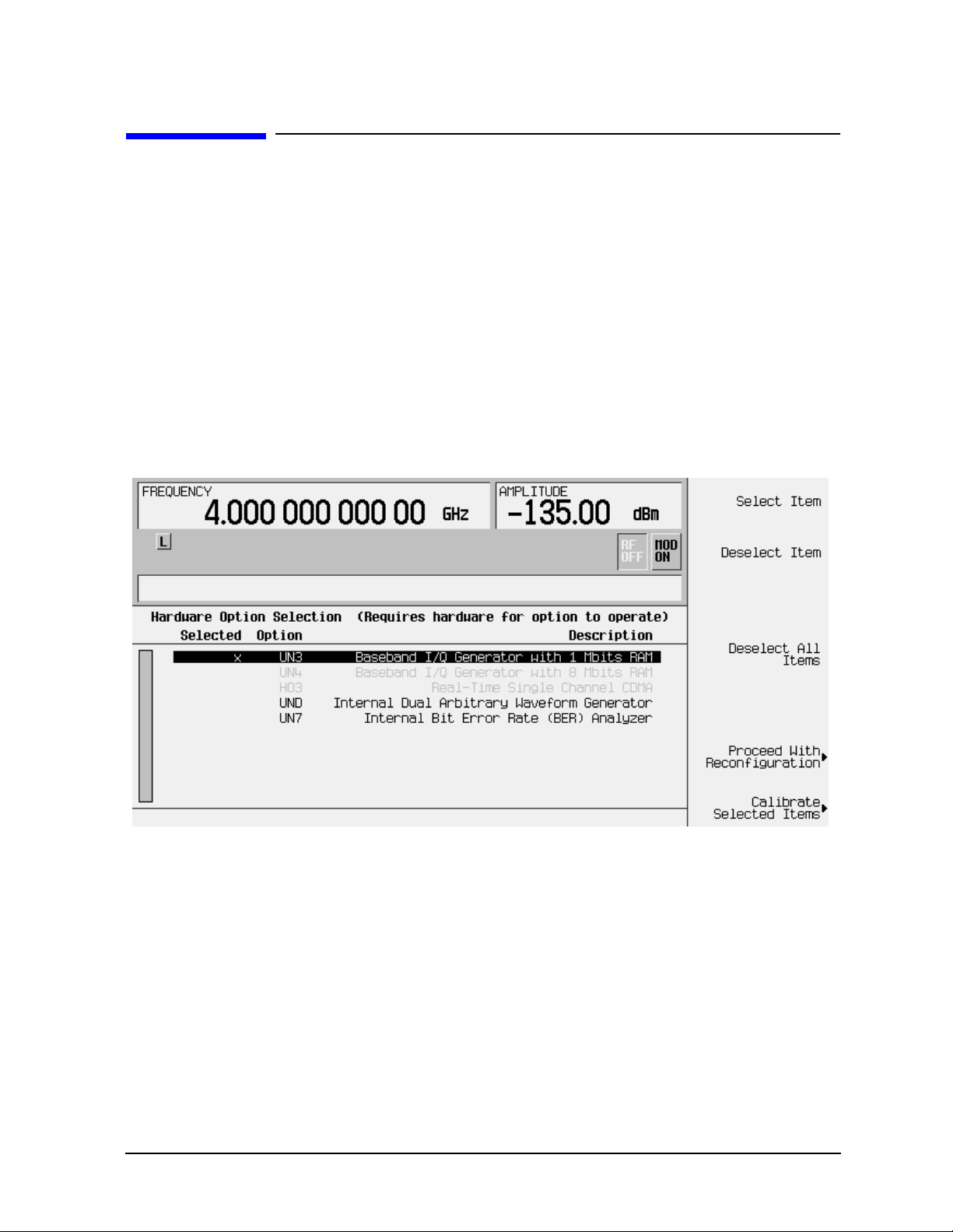
2. Next, on the signal generator press
the Hardware Options menu. An example of the signal generator display follows:
The display indicates which options are currently enabled for the signal generator. In
this case Option UN3 is enabled, as indicated by the X placed in the “Selected” column.
Utility, Instrument Adjustments, Hardware Options to access
3. Highlight the new option that you have just installed. (Use the up/down arrow keys or
the front panel knob.)
4. Press the Select Item softkey. An X will be placed in the “Selected” column.
Two other selection keys are available in this menu to help you identify the proper
options to be enabled. Deselect Item removes the X from the “Selected” column in the
highlighted option.
column.
User’s Guide 2-13
Deselect All Items removes all occurrences of the X from the “Selected”
Page 28

Using Functions HP ESG and HP ESG-D Series Signal Generators
Enabling Options
5. Press Proceed With Configuration to enable all selected options. After pressing this softkey,
press the
Confirm Change softkey to verify that you do want to reconfigure the signal
generator with the options that you have selected. If you do not want to continue, press
the
Return key.
CAUTION If you enable an option that does not have the required hardware installed,
the menus for that option will be activated but the option cannot operate,
despite what the menus may seem to indicate.
6. Once you have installed optional hardware in your signal generator, perform a
download of calibration data from the hardware into non-volatile memory by pressing
Calibrate Selected Items. To confirm that you want to start the calibration, press the Start
Calibration and Store Results
softkey. The calibration takes several minutes. During the
calibration, a message is displayed indicating the calibration is in progress and showing
the percent complete. When the calibration is finished, the Hardware Options menu is
returned.
Enabling a Software Option
1. A license key is required to enable each software option. This license key is provided on
the license key certificate that you receive when you purchase the software option.
Access the Software Options menu by pressing
Options
. An example of the signal generator display follows:
Utility, Instrument Adjustments, Software
Verify that the host ID shown on the display matches the host ID on the license key
certificate. The host ID is a unique number for every instrument. If the host ID on the
license key certificate does not match your instrument, the license key cannot enable
the software option.
2-14 User’s Guide
Page 29

HP ESG and HP ESG-D Series Signal Generators Using Functions
Enabling Options
2. On the display is a list of software options that are already enabled (if any) and the
software options that can be enabled. Software options are linked to specific hardware
options. Before a software option can be enabled, the appropriate hardw are option must
be installed. For example, Option UN5, Multi-Channel CDMA, requires that
Option UND, Internal Dual Arbitrary W a veform Generator, be installed. If the software
option that you intend to install is listed in a grey font, the required hardware may not
be installed. (Look for an X in the “Selected” column of the appropriate hardware option
in the Hardware Options menu.)
3. To enable the software option, highlight the desired option using the up/down arrow
keys or the front panel knob.
4. Press
Modify License Key. Enter the 12-character license key (from your license key
certificate) using the softkeys and numeric keypad. When you have finished, press the
Enter terminator softkey.
5. Press
Proceed With Reconfiguration. Press the Confirm Change softkey to verify that you do
want to reconfigure the signal generator with the options for which you have provided a
license key. The instrument will enable the options and reboot.
User’s Guide 2-15
Page 30

Using Functions HP ESG and HP ESG-D Series Signal Generators
Enabling Options
2-16 User’s Guide
Page 31

HP ESG and HP ESG-D Series Signal Generators
3Troubleshooting
This chapter contains instructions for troubleshooting problems you may encounter during
operation of the signal generator, it explains error messages you might see, and it explains
how to return your signal generator to HP for service.
User’s Guide 3-1
Page 32

Troubleshooting HP ESG and HP ESG-D Series Signal Generators
If You Encounter a Problem
If You Encounter a Problem
If the signal generator is not operating as you expected, look for help in the following list of
symptoms and possible solutions. If you do not find a solution here, refer to the service
guide.
No RF Output?
The front panel RF On/Off key must be set to On before the RF signal is available at the
RF OUTPUT connector . Check the annunciator on the displa y. If it reads
RF On/Off key once to toggle the RF output on.
RF Output Power too Low?
If the RF output power seems too low, look for an OFFSET or REF indicator in the amplitude
area of the display.
OFFSET tells you that an amplitude offset has been set. An amplitude offset changes the
value shown in the amplitude area of the display but does not affect the output power. The
amplitude displayed is equal to the current power output by the signal generator hardware
plus the value for the offset. To eliminate the offset, press
the numeric keypad and press the
dB terminator softkey.
Ampl, Ampl Offset. Enter 0 using
RF OFF, press the
REF tells you that the amplitude reference mode is turned on. When this mode is on, the
displayed amplitude value is not the output power level; rather, it is the current power
output by the signal generator hardware minus the reference value set by the
softkey. To exit the reference mode, press Ampl and toggle the Ampl Ref softkey to Off. You
can then reset the output power to the desired level.
Ampl Ref Set
Optional Features are Not Working?
If you enable an option that does not have the required hardware installed, the menus for
that option will be activated but the option cannot operate, despite what the menus may
seem to indicate. Check to be sure that the required hardware is physically installed in the
signal generator.
If a software option is disabled but should be enabled, try the following suggestions for
resolution:
• Verify that the optional hardware is installed.
• Verify that the hardware option is enabled.
• Verify that the software option is enabled with the correct license key. Refer to your
License Key Certificate for the correct license key or, if your option was installed by HP,
contact your HP service office with the instrument model number, the host ID, and the
software option that should be enabled.
3-2 User’s Guide
Page 33

HP ESG and HP ESG-D Series Signal Generators Troubleshooting
If You Encounter a Problem
No Modulation at the RF Output?
Although you can set up and enable various modulations, the RF carrier is modulated by
the enabled modulation only when you have also set
annunciator on the display. If it reads
modulation on.
MOD OFF, press the Mod On/Off key once to toggle the
Mod On/Off to On. Check the
Can’t Turn Off Sweep Mode?
In the sweep mode menu you can choose to set the sweep to various sweep types or to turn
sweep off. Press
Sweep/List, Sweep and choose Off from the sweep mode selections.
Recalled a Register and Sweep List is Missing?
Sweep information is not stored as part of the instrument state in a storage register. Only
the current step and list sweep is available to the signal generator and it cannot be stored
nor will it survive a factory preset.
All of the Registers Where You Previously Stored Instrument
States are Empty?
The save/recall registers are backed-up by a battery when AC power to the signal
generator is not connected. The battery may need to be replaced. T o verify that the battery
has failed, turn off line power to the signal generator and unplug it. Then plug in the
instrument and cycle power on. If either error message −311 or −700 is stored in the error
message queue, your battery has failed. Refer to the service guide for battery replacement
instructions.
Saved an Instrument State in a Register but the Register is
Empty or Contains the Wrong State?
If you have intentionally, or unintentionally, selected a register number that is greater
than 99, the signal generator will automatically select register 99 to save your instrument
state. If the register number you intended to use is empty or contains the wrong
instrument state, recall register 99 as the instrument state may be saved there.
The Power Supply has Shut Down?
If the power supply is not working, it requires repair or replacement. There is no
user-replaceable power supply fuse. Refer to the service guide for instructions.
User’s Guide 3-3
Page 34

Troubleshooting HP ESG and HP ESG-D Series Signal Generators
If You Encounter a Problem
Incorrect List Sweep Dwell Time?
If the signal generator does not dwell for the correct period of time at each sweep list point,
first check the sweep list dwell values for accuracy. Press
the sweep list values will be displayed. Edit the dwell values if they are incorrect. (Note:
The effective dwell time at the RF OUTPUT connector is the sum of the value set for the
dwell plus processing time, attenuator switching time, and settling time. This additional
time added to the dwell is generally a few milli-seconds. The TTL output, however,
available at the TRIGGER OUT connector, is asserted high only during the actual dwell
time.)
Sweep/List, Configure List Sweep and
If the list dwell values are correct, check to see if the
Step. When Step is selected, the signal generator will sweep the list points using the dwell
Dwell Type List Step softkey is set to
time set for step sweep rather than the sweep list dwell values. To view the step sweep
dwell time, press
Configure Step Sweep and observe the value set for the Step Dwell softkey.
Can’t Turn Off Help Mode?
There are two help modes (single and continuous) available on the signal generator. In
single mode (the factory preset condition) when you press the
Help key, help text is provided
for your next key press. Now press any key and you will exit the help function and the
function of the key you pressed is also executed. When you are in continuous help mode,
when you press the
function is also executed (except for the
you press the
Instrument Info/Help Mode and toggle the Help Mode Single Cont softkey to Single.
Help key again. To change from continuous to single mode, press Utility,
Help key, help text is provided for your next key press and that key’s
Preset key). You will stay in this help mode until
LF OUTPUT Signal is a Sinewave but the RF OUTPUT Signal is
a Pulse Squarewave?
The LF OUTPUT connector will output a signal where the frequency and shape is set by
the internal source as it is being used by a modulation. However, if you are generating a
pulse squarewave, the LF OUTPUT signal is correctly output as a sinewave. That
sinewave is later squared by the modulator to generate the pulse modulation.
Signal Generator is Locked Up?
If your signal generator is locked up, try the following suggestions for resolution:
• Make sure that the signal generator is not in remote mode. (The
turned on in the display.) Press the
Local key to halt remote mode and return to listen
mode.
• Make certain that the signal generator is not in a local lockout condition.
• Check for a progress bar on the signal generator display which indicates that an
operation is in progress.
• Try an instrument preset.
• Try cycling power.
3-4 User’s Guide
R annunciator will be
Page 35

HP ESG and HP ESG-D Series Signal Generators Troubleshooting
If You Encounter a Problem
If none of the previous suggestions resolves the problem, you can try the fail-safe recovery
sequence. This sequence should only be used as a last resort as it will reset the signal
generator but the process will destroy all user files (instrument state, sequence files, data
files), calibration data (unsaved I/Q calibrations, DCFM/DCΦM calibrations), and the
persistent state. Do not attempt to perform any other front panel or remote operations
during the fail-safe sequence.
To run the fail-safe sequence, hold down the
hold down the
Preset key until the ESG fail-safe recovery sequence message is displayed.
Preset key while cycling power. Continue to
CAUTION Carefully read the entire message! It may list additional risks with the
procedure beyond what is documented here.
Release the
Preset key and press Yes to continue with the sequence (or No to abort with no
lost files).
At the conclusion of the sequence, perform the following steps:
1. Cycle power once again. Cycling power restores all previously installed options. You
should expect to see several error messages resulting from calibration files being
restored from EEPROM.
2. Perform the DCFM/DCΦM calibration. (Refer to the
DCFM/DCΦM Cal softkey description
in Chapter 5, “Hardkey and Softkey Reference,” in this manual.)
3. For HP ESG-D Series Signal Generators only, perform the I/Q calibration. (Refer to the
I/Q Calibration softkey description in Chapter 5, “Hardkey and Softkey Reference,” of this
manual.)
4. Hewlett-Packard is interested in the circumstances that caused you to have to initiate
this procedure. Please contact us at 1 800 452-4844. We’d like to help you eliminate any
repeat occurrences.
User’s Guide 3-5
Page 36

Troubleshooting HP ESG and HP ESG-D Series Signal Generators
Error Messages
Error Messages
If an error condition occurs in the signal generator, it is reported to both the front panel
display error queue and the SCPI (remote interface) error queue. These two queues are
viewed and managed separately.
NOTE When there is an unviewed message in the front panel error queue, the ERR
annunciator appears on the signal generator’s display.
Table 3-1 Characteristics of the Error Queues
Characteristic
Capacity (#errors) 30 30
Overflow Handling Circular (rotating).
Viewing Entries Press: Utility, Error Info, View
Clearing the Queue Press: Utility, Error Info, Clear
Permanent Errors
(errors that must be
resolved, for example:
unlock, ovencold, and
hi/lo)
Front Panel Display
Error Queue
Drops oldest error as new
error comes in.
Next
(or Previous) Error
Message
Error Queue(s)
Re-reported after queue is
cleared.
Linear, first-in/first-out.
Replaces newest error with:
-350,Queue overflow
Use SCPI query
Power up
Send a *CLS command
Read last item in the queue
Re-reported after queue is
cleared.
SCPI Remote Interface
Error Queue
SYSTem:ERRor? or
STATus:QUEue?
3-6 User’s Guide
Page 37

HP ESG and HP ESG-D Series Signal Generators Troubleshooting
Error Message Format
Error Message Format
The system-defined error numbers are chosen on an enumerated (“1 of N”) basis. The
SCPI-defined error numbers and the <error_description> portions of the error query
response are displayed on the instrument.
In this chapter, an explanation is included with each error to further clarify its meaning.
The last error described in each class (for example, -400, -300, -200, -100) is a “generic”
error. In selecting the proper error number to report, more specific error codes are
preferred.
Error messages appear in the lower-left corner of the display.
Error Message Example
User’s Guide 3-7
Page 38

Troubleshooting HP ESG and HP ESG-D Series Signal Generators
Error Message Types
Error Message Types
Events do not generate more than one type of error . For example, an event that generates a
query error will not generate a device-specific, execution, or command error.
-499 to -400: Query Errors indicate that the instrument’s output queue control has detected a
problem with the message exchange protocol described in IEEE 4888.2, chapter 6. Errors
in this class set the query error bit (bit 2) in the event status register (IEEE 488.2, section
11.5.1). These errors correspond to message exchange protocol errors described in IEEE
488.2, 6.5. In this case:
• Either an attempt is being made to read data from the output queue when no output is
either present or pending, or
• data in the output queue has been lost.
-399 to -300: Device-Specific Errors indicate that a device operation did not properly complete,
possibly due to an abnormal hardware or firmware condition. These codes are also used for
self-test response errors. Errors in this class set the device-specific error bit (bit 3) in the
event status register (IEEE 488.2, section 11.5.1).
The <error_message> string for a positive error is not defined by SCPI. A positive error
indicates that the instrument detected an error within the HP-IB system, within the
instrument’s firmware or hardware, during the transfer of block data, or during
calibration.
-299 to -200: Execution Errors indicate that an error has been detected by the instrument’s
execution control block. Errors in this class set the execution error bit (bit 4) in the event
status register (IEEE 488.2, section 11.5.1). In this case:
• Either a <PROGRAM DATA> element following a header was evaluated by the device
as outside of its legal input range or is otherwise inconsistent with the device’s
capabilities, or
• a valid program message could not be properly executed due to some device condition.
Execution errors are reported after rounding and expression evaluation operations are
completed. Rounding a numeric data element, for example, is not reported as an execution
error.
-199 to -100: Command Errors indicate that the instrument’s parser detected an IEEE 488.2
syntax error. Errors in this class set the command error bit (bit 5) in the event status
register (IEEE 488.2, section 11.5.1)t. In this case:
• Either an IEEE 488.2 syntax error has been detected by the parser (a control-to-device
message was received that is in violation of the IEEE 488.2 standard. Possible
violations include a data element which violates device listening formats or whose type
is unacceptable to the device.), or
• an unrecognized header was received. These include incorrect device-specific headers
and incorrect or unimplemented IEEE 488.2 common commands.
3-8 User’s Guide
Page 39

HP ESG and HP ESG-D Series Signal Generators Troubleshooting
0: No Error
0: No Error
0 No error
The queue is empty. Every error in the queue has been read or the queue
was purposely cleared by power-on or
*CLS.
User’s Guide 3-9
Page 40

Troubleshooting HP ESG and HP ESG-D Series Signal Generators
-499 to -400: Query Errors
-499 to -400: Query Errors
The instrument’s output queue control has detected a problem with the message exchange
protocol described in IEEE 4888.2, chapter 6. Errors in this class set the query error bit
(bit 2) in the event status register (IEEE 488.2, section 11.5.1). These errors correspond to
message exchange protocol errors described in IEEE 488.2, 6.5.
In this case, either an attempt is being made to read data from the output queue when no
output is either present or pending, or data in the output queue has been lost.
-440
-430
-420
Query UNTERMINATED after indefinite response
Indicates that a query was received in the same program message after a
query requesting an indefinite response was executed (see IEEE 488.2,
6.3.7.5).
Query DEADLOCKED
Indicates that a SCPI output queue has filled, preventing further SCPI
command execution, and there is no more room left in the corresponding
SCPI input queue to accept a query to read from the output queue. The
system automatically discards output to correct the deadlock.
Query DEADLOCKED
Indicates that a condition causing a DEADLOCKED query error occurred
(see IEEE 488.2, 6.3.1.7). For example, both the input buffer and the
output buffer are full and the device cannot continue.
Query UNTERMINATED
Indicates that a condition causing an UNTERMINATED query error
occurred (see IEEE 488.2, 6.3.2.2). For example, the device was addressed
to talk and an incomplete program message was received.
-410
Query INTERRUPTED
Indicates that a condition causing an INTERRUPTED query error
occurred (see IEEE 488.2, 6.3.2.7). For example, a query was followed by
DAB or
GET before a response was completely sent.
-400 Query Error
This is a generic query error for devices that cannot detect more specific
errors. The code indicates only that a query error as defined in IEE 488.2,
11.5.1.1.7 and 6.3 has occurred.
3-10 User’s Guide
Page 41

HP ESG and HP ESG-D Series Signal Generators Troubleshooting
-399 to -300: Device-Specific Errors
-399 to -300: Device-Specific Errors
Some device operations did not properly complete, possibly due to an abnormal hardware
or firmware condition. These codes are also used for self-test response errors. Errors in this
class set the device-specific error bit (bit 3) in the event status register (IEEE 488.2,
section 11.5.1).
-362
-361
-360
-350
-340
Framing error in program message
Indicates that a stop bit was not detected when data was received (for
example, a baud rate mismatch).
Parity error in program message
Indicates that the parity bit was not correct when data was received (for
example, an incorrect parity bit on a serial port).
Communication error
This is the generic communication error for devices that cannot detect the
more specific errors described for errors -361 through -363.
Queue overflow
This is a specific code entered into the queue in lieu of the code that caused
the error. This message indicates that there is no more room in the queue
and an error occurred but was not recorded.
Calibration failed
Indicates that the device has detected a failure during its calibration
procedure.
-330
Self-test failed; Power supply self-test failure
Indicates that the self-test for a particular power supply voltage has failed.
The instrument is likely not functional. Report this error to the nearest
Hewlett-Packard sales and service office.
Self-test failed; EEPROM header checksum error <card_name>.
Indicates that the card identification header for a hardware card is
incorrect. If the card is not properly identified, the instrument is likely to
be non-functional. Report this error to the nearest Hewlett-Packard sales
and service office.
User’s Guide 3-11
Page 42

Troubleshooting HP ESG and HP ESG-D Series Signal Generators
-399 to -300: Device-Specific Errors
Self-test failed; Data Generator Memory Test @ 0x____
Indicates that the data generator memory failed. Modulation data
produced by the data generator may not be correct. However, if an Unable
to check Data Generator Memory error was also seen, this result is not
conclusive. The address of the first location that failed is reported. Report
this error to the nearest Hewlett-Packard sales and service office.
Self-test failed; Burst Generator Memory Test @ 0x____
Indicates that the burst generator memory failed. Modulation data
produced by the burst generator may not be correct. However, if an
to check Burst Generator Memory error was also seen, this result is not
Unable
conclusive. The address of the first location that failed is reported. Report
this error to the nearest Hewlett-Packard sales and service office.
Self-test failed; Bad address position @ 0x____
Indicates that the data generator memory failed. Modulation data
produced by the data generator may not be correct. An address that
appeared to have a failed address line was reported. Report this error to
the nearest Hewlett-Packard sales and service office.
-321
Self-test failed; Chips ___, ___ aliased @ 0x____
Indicates that the data generator memory failed. Modulation data
produced by the data generator may not be correct. An address that
appeared to be aliased across multiple memory chips has been reported.
Report this error to the nearest Hewlett-Packard sales and service office.
Self-test failed
Indicates that the device has detected a failure during its self-test
procedure.
Out of memory; The table editor cannot function properly until
more memory is available.
Indicates that there is insufficient working memory available. Reduce the
size of any sweep lists and try again.
Out of memory; Unable to verify instrument state file.
Indicates that an instrument state file could not be accessed and verified
because of insufficient memory. Reduce the size of any sweep lists and try
again.
3-12 User’s Guide
Page 43

HP ESG and HP ESG-D Series Signal Generators Troubleshooting
-399 to -300: Device-Specific Errors
Out of memory; Memory catalog failed.
Indicates that there is not enough memory to complete a catalog listing.
Reduce the size of any sweep lists and try again.
Out of memory; Unable to display timeslot window.
Indicates that the instrument was unable to create part of the graphical
user interface due to an inability to allocate memory (possibly due to
fragmentation). Report this error to the nearest Hewlett-Packard sales
and service office. The instrument is still functional.
Out of memory; Unable to display protocol window.
Indicates that the instrument was unable to create part of the graphical
user interface due to an inability to allocate memory (possibly due to
fragmentation). Report this error to the nearest Hewlett-Packard sales
and service office. The instrument is still functional.
Out of memory; Unable to display format window.
Indicates that the instrument was unable to create part of the graphical
user interface due to an inability to allocate memory (possibly due to
fragmentation). Report this error to the nearest Hewlett-Packard sales
and service office. The instrument is still functional.
Out of memory; Cannot uncompress file.
Indicates that a STATE: file cannot be uncompressed because there is not
enough memory to run the decompression algorithm. Recall will fail and
there will be no instrument state change. Reduce the size of any sweep
lists and try again.
Out of memory; Cannot precalculate frequencies. Try fewer
frequencies.
Indicates that memory was exhausted during frequency precalculation
(used to speed the process of sweep/list mode). List mode cannot run until
either fewer frequencies have been supplied or more memory becomes
available and the same set of frequencies are sent again,
executed, or
:FREQ:MODE LIST is executed.
FREQ:MODE CW is
Out of memory; Object Memory Area
Indicates that memory was exhausted during instrument power-on.
Report this error to the nearest Hewlett-Packard sales and service office.
User’s Guide 3-13
Page 44

Troubleshooting HP ESG and HP ESG-D Series Signal Generators
-399 to -300: Device-Specific Errors
Out of memory; List formation
The device was unable to allocate space for a lookup table, such as for list
mode precalculation. List mode cannot run until either fewer frequencies
have been supplied or more memory becomes available and the same set of
frequencies are sent again,
FREQ:MODE CW is executed, or :FREQ:MODE LIST
is executed.
Out of memory; PRBS xx/xx
There was not enough memory to apply a scramble to data for the
baseband generator. In this case, the scramble is not applied to the
generator.
Out of memory; Display system out of memory. An abnormal display
may result. Memory consumption should be reduced.
There was not enough memory in the system to properly update the
display. Some inconsistencies may be seen. The size of any list/sweep
should be reduced, and the source should be preset to clear up any
inconsistencies. Report this error to the nearest Hewlett-Packard sales
and service office.
Out of memory; Unable to check Data Generator memory.
Indicates that there was not enough memory in the system to properly
complete the data generator memory test. This does not imply a data
generator memory failure. Check all other error messages to identify
possible causes, discontinue list/sweep mode to free some memory, and
repeat the test.
Out of memory; Insufficient RAM
Indicates that a memory comparison between a shadow RAM data area
and the corresponding EEPROM data area could not be performed due to
insufficient working RAM. This does not necessarily imply a memory
problem, since this comparison is only used in stringent diagnostic
situations.
Out of memory; Cannot create memory manager
Indicates that a file system memory manager detected an internal error
condition. Report this error to the nearest Hewlett-Packard sales and
service office.
3-14 User’s Guide
Page 45

HP ESG and HP ESG-D Series Signal Generators Troubleshooting
-399 to -300: Device-Specific Errors
Out of memory; Memory request failed, out of indices. Memory
request greater than total memory size.
Indicates that a file system memory manager detected an internal error
condition. Report this error to the nearest Hewlett-Packard sales and
service office.
Out of memory; File exceeds digital modulation memory size.
Indicates that a digital modulation input file would result in more pattern
data being generated than can fit in the pattern memory.
Out of memory; There is insufficient memory to copy the current
pattern. The secondary pattern is unchanged.
Indicates that there was insufficient room to copy or create the current
data generation pattern data in order to make it a secondary pattern. To
avoid this, set up the smaller of the two patterns first.
Out of memory; There is insufficient memory to store the
secondary frame in Pattern RAM. The secondary frame has been
turned off.
Indicates that there was insufficient room to copy or create the current
data generation pattern data in order to make it a secondary pattern. To
avoid this, set up the smaller of the two patterns first.
Out of memory; The table editor cannot function properly until
more memory is available.
Indicates that there is insufficient working memory available. Reduce the
size of any sweep lists and try again.
Out of memory; Pattern exceeds digital modulation memory size.
If a user file is selected, it may be too large.
Indicates that the user has specified a data file or other generation
parameters that would require more data generation pattern memory
than is available with the particular data generator installed in the
instrument.
Out of memory; ARB communication failed.
Indicates that there was insufficient memory to complete the dual
arbitrary waveform generator (Option UND) communications. Report this
error to the nearest Hewlett-Packard sales and service office.
User’s Guide 3-15
Page 46

Troubleshooting HP ESG and HP ESG-D Series Signal Generators
-399 to -300: Device-Specific Errors
Out of memory; FIR system unable to operate.
Indicates that there is insufficient working memory available.
Out of memory; Burst shape RAM cannot hold specified burst
shape.
Indicates that there is insufficient working memory available. Report this
error to the nearest Hewlett-Packard sales and service office.
Out of memory; Histogram display cannot function.
Indicates that there is insufficient working memory available. Report this
error to the nearest Hewlett-Packard sales and service office.
Out of memory; Impulse response display cannot function.
Indicates that there is insufficient working memory available. Report this
error to the nearest Hewlett-Packard sales and service office.
Out of memory
Indicates that there is insufficient working memory available. Report this
error to the nearest Hewlett-Packard sales and service office.
Out of memory; FFT subsystem cannot function.
Indicates that there is insufficient working memory available. Report this
error to the nearest Hewlett-Packard sales and service office.
Out of memory; FFT display cannot function.
Indicates that there is insufficient working memory available. Report this
error to the nearest Hewlett-Packard sales and service office.
Out of memory; Complementary Cumulative Distribution. Display
cannot function.
Indicates that there is insufficient working memory available. Report this
error to the nearest Hewlett-Packard sales and service office.
Out of memory; I/Q map display cannot function.
Indicates that there is insufficient working memory available. Report this
error to the nearest Hewlett-Packard sales and service office.
3-16 User’s Guide
Page 47

HP ESG and HP ESG-D Series Signal Generators Troubleshooting
-399 to -300: Device-Specific Errors
Out of memory; Graph subsystem cannot function.
Indicates that there is insufficient working memory available. Report this
error to the nearest Hewlett-Packard sales and service office.
Out of memory; FIR subsystem generated more coefficients than
the hardware can handle.
Indicates that there is insufficient working memory available. Report this
error to the nearest Hewlett-Packard sales and service office.
Out of memory; Modulation subsystem unable to operate.
Indicates that there is insufficient working memory available. Report this
error to the nearest Hewlett-Packard sales and service office.
Out of memory
Insufficient working memory during arbitrary waveform generation.
Report this error to the nearest Hewlett-Packard sales and service office.
Out of memory
Indicates that an internal operation needed more memory than was
available.
Out of memory
Indicates that there was insufficient working memory during data
generation pattern calculations. Reduce the size of any sweep lists and try
again.
Out of memory
If this occurs during a memory catalog display, it means the system did not
have enough free RAM to prepare the catalog.
Out of memory; The table editor cannot function properly until
more memory is available.
There is insufficient memory to the ARB to generate the requested
waveform.
Out of memory; ARB is not functional.
There is insufficient memory to the ARB to generate the requested
waveform.
User’s Guide 3-17
Page 48

Troubleshooting HP ESG and HP ESG-D Series Signal Generators
-399 to -300: Device-Specific Errors
-320 Storage fault
Indicates that the firmware detected a fault when using data storage. This
error is not an indication of physical damage or failure of any mass storage
element.
-315
Configuration memory lost; Persistent state preset. Using
factory defaults.
Indicates that the persistent state has been forced to return to factory
preset values.
Configuration memory lost; Persistent state version is bad.
Using factory defaults.
Indicates that the persistent state version is not recognized as valid and is
assumed to be corrupt. The persistent state is reinitialized with the
factory preset values.
Configuration memory lost; Persistent state checksum is bad.
Using factory defaults.
Indicates that the persistent state is corrupt and had to be reinitialized
with the factory preset values.
Configuration memory lost
Indicates that non-volatile configuration data saved by the device has been
lost. The meaning of this error is device-dependent.
-314
Save/recall memory loss
Indicates that the non-volatile data saved by the *SAV? command has been
lost.
-313
Calibration memory lost
Indicates that non-volatile calibration data has been lost.
-312 PUD memory lost
Indicates that the protected user data saved by the *PUD command has
been lost.
3-18 User’s Guide
Page 49

HP ESG and HP ESG-D Series Signal Generators Troubleshooting
-399 to -300: Device-Specific Errors
-311 Memory error; Unable to configure Save Recall registers from
non-volatile memory. Save Recall registers re-initialized.
Indicates that saved states are no longer usable. Delete explicitly using
Catalog.
Memory error
Indicates that an error was detected in the device’s memory.
-310 System error; RS232 buffer overflow: character lost.
Indicates that the RS232 buffer has been exceeded. The most recent
character has been dropped.
System error; Cannot change manual point until list mode error
condition cleared.
An error is keeping the sweep/list from being able to set the frequency
and/or power. Until the problem is addressed, the manual point cannot be
changed.
-300
System error; Unable to determine which attenuator is
installed.
Indicates that an invalid attenuator identification code has been detected.
Possible causes include a loose attenuator control cable. The instrument
will likely not produce the proper output power levels. Report this error to
the nearest Hewlett-Packard sales and service office.
System Error; FIR subsystem generated more coefficients than
the hardware can handle.
Indicates that the maximum number of coefficients for a given set of
hardware has been exceeded. The filter must be created with fewer
coefficients.
Device-specific error
This is a generic device-dependent error for devices that cannot detect
more specific errors. The code indicates only that a device-dependent error
as defined in IEEE 488.2, 11.5.1.1.6 has occurred.
User’s Guide 3-19
Page 50

Troubleshooting HP ESG and HP ESG-D Series Signal Generators
-299 to -200: Execution Errors
-299 to -200: Execution Errors
An error has been detected by the instrument’s execution control block. Errors in this class
set the execution error bit (bit 4) in the event status register (IEEE 488.2, section 11.5.1).
In this case:
• Either a <PROGRAM DATA> element following a header was evaluated by the device
as outside of its legal input range or is otherwise inconsistent with the device’s
capabilities, or
• a valid program message could not be properly executed due to some device condition.
Execution errors are reported after rounding and expression evaluation operations are
completed. Rounding a numeric data element, for example, is not reported as an execution
error.
-294
Incompatible type
Indicates that the type or structure of a memory item is inadequate.
-293 Referenced name already exists
A downloaded program attempted to define an element (a variable,
constant, filename, etc.) that had already been defined.
-292
Referenced name does not exist
A downloaded program attempted to access an undefined element
(a variable, constant, filename, etc.).
-291
Out of memory
A downloaded program required more memory than was available in the
instrument.
-290
Memory use error
Indicates that a user request has directly or indirectly caused an error
related to memory or <data_handles>. This is not the same as “bad”
memory.
-286
Program runtime error; Floating-Point Exception
Indicates that a floating-point math error (such as a divide by zero) has
been detected. The system will attempt to recover automatically. Report
this error to the nearest Hewlett-Packard sales and service office.
3-20 User’s Guide
Page 51

HP ESG and HP ESG-D Series Signal Generators Troubleshooting
-299 to -200: Execution Errors
Program runtime error
Indicates that a runtime error was detected in a downloaded program.
-285 Program syntax error
Indicates that a syntax error appears within a downloaded program. The
syntax used when parsing a downloaded program is device-specific.
-284
Program currently running
Indicates that certain operation related to programs may be illegal while
the program is running. For example, deleting a running program may be
illegal.
-283
Illegal variable name
Indicates that an attempt was made to reference a nonexistent variable.
-282 Illegal program name
Indicates that the name used to reference a program was invalid. For
example, redefining an existing program, deleting a nonexistent program,
or in general, referencing a nonexistent program.
-281
Cannot create program
Indicates that an attempt to create a program was unsuccessful. This may
be due to insufficient memory.
-280
Program error
Indicates that a downloaded program-related execution error occurred.
This error message is used when the device cannot detect the more specific
errors described for errors -281 through -289. The syntax used in a
program and the mechanism for downloading a program is device-specific.
-278
Macro header not found
Indicates that a syntactically legal macro label in the *GMC? query could
not be executed because the header was not previously defined.
-277
Macro redefinition not allowed
Indicates that the macro label defined in the *DMC command could not be
executed because the macro label was already defined (see IEEE 488.2,
10.7.6.4).
User’s Guide 3-21
Page 52

Troubleshooting HP ESG and HP ESG-D Series Signal Generators
-299 to -200: Execution Errors
-276 Macro recursion error
Indicates that a syntactically legal macro program data sequence could not
be executed because the device found it to be recursive (see IEEE 488.2,
10.7.6.4).
-275
-274
-273
-272
Macro definition too long
Indicates that a syntactically legal macro program data sequence could not
be executed because the string or block contents were too long for the
device to handle (see IEEE 488.2, 10.7.6.1).
Macro parameter error
Indicates that the macro definition improperly used a macro parameter
placeholder (see IEEE 488.2, 10.7.3).
Illegal macro label
Indicates that the macro label defined in the *DMC command was a legal
string syntax, but could not be accepted by the device (see IEEE 488.2,
10.7.3 and 10.7.6.2). For example, the label was too long, the same as a
common command header, or contained invalid header syntax.
Macro execution error
Indicates that a syntactically legal macro program data sequence could not
be executed due to an error within the macro definition (see IEEE 488.2,
10.7.6.3).
-271
Macro syntax error
Indicates that a syntactically legal macro program data sequence, written
in accordance with IEEE 488.2, 10.7.2, could not be executed due to a
syntax error within the macro definition (see IEEE 488.2, 10.7.6.3).
-270
Macro error
Indicates that a macro-related execution error occurred. This error
message is used when the device cannot detect the more specific errors
described for errors -271 through -279.
-261
Math error in expression
Indicates that a syntactically legal expression program data element could
not be executed due to a math error. For example, a divide-by-zero was
attempted. The definition of a math error is device-specific.
3-22 User’s Guide
Page 53

HP ESG and HP ESG-D Series Signal Generators Troubleshooting
-299 to -200: Execution Errors
-260 Expression error
Indicates that an expression data element-related error occurred. This
error message is used when the device cannot detect the more specific
errors described for errors -261 through -269.
-258
-257
Media protected
Indicates that the device or user has attempted to write to a read-only
memory subsystem (msus). The definition of a protected media is
device-specific.
File name error; Delete empty sequence <sequence_name>. Delete
sequence ignored.
Indicates that the user has attempted to delete a sequence which is empty
(all registers unused). This is informational only. Typically this error is
reported (several times) when the “Delete All Sequences” command is
executed.
File name error; Delete a non-saved state register. Delete
register ignored.
Indicates that the user has attempted to delete a state which is empty
(unused). This is informational only.
File name error; Directory does not support extenders.
Indicates that an extender, which is specified by an @ sign followed by a
memory subsystem name, has been specified for an explicit memory
subsystem which does not allow the
@ notation. Only the default (:)
memory subsystem allows extenders.
File name error; Empty filename
Indicates that a filename of “ “ was specified. This is not a legal filename.
File name error; Illegal extender
Indicates that an illegal memory subsystem name was used after the @.
File name error; Illegal filename character
Indicates that an illegal character was used within a filename. \, :, @ and
all non-printable ASCII characters are illegal in filenames.
User’s Guide 3-23
Page 54

Troubleshooting HP ESG and HP ESG-D Series Signal Generators
-299 to -200: Execution Errors
File name error; Only one “:” is allowed.
Indicates that only one colon is allowed in any filename specification. The
text before the colon is a user memory subsystem.
File name error; Only one “@” is allowed.
Indicates that only one @ is allowed in any filename specification. It
specifies the memory subsystem that a user file actually resides in.
File name error
Indicates that a legal program command or query could not be executed
because a file name on the device media was in error. For example, an
attempt was made to copy to a duplicate filename. The definition of what
constitutes a file name error is device-specific.
-256
File name not found; The internal list file was not found. There
is no list data to return
Indicates that the DWEL_FILE, FREQ_FILE, or POW_FILE has been lost, so a
new one will have to be created. These files are the persistent information
for list/sweep mode. They contain the dwell list, the frequency list, or the
power list. Invoking the list editor will recreate the missing file to a length
of one element.
File name not found; <filename>
Indicates that the user has attempted to delete a file that does not exist.
File name not found; CDMA_DATA FILE
One of the internal working CDMA channel table files is missing.
File name not found; CDMA_WCODE FILE
One of the internal working CDMA channel table files is missing.
File name not found; CDMA_POW FILE
One of the internal working CDMA channel table files is missing.
File name not found; CDMA_PNOFS FILE
One of the internal working CDMA channel table files is missing.
3-24 User’s Guide
Page 55

HP ESG and HP ESG-D Series Signal Generators Troubleshooting
-299 to -200: Execution Errors
File name not found
Indicates that a legal program command or query could not be executed
because the file name on the device media could not be found. For example ,
an attempt was made to read or copy a nonexistent file. The definition of
what constitutes a file not being found is device-specific.
-255
-254
Directory full
Indicates that a legal program command or query could not be executed
because the media directory was full. The definition of what constitutes a
full media directory is device-specific.
Media full; Unable to delete saved state from non-volatile
memory. No instrument state change.
Indicates that the state memory subsystem STATE: was unable to delete a
register. You must free some memory by deleting a file or register using
Catalog. Afterwards, try again.
Media full; Save a state register ignored.
Indicates that the state memory subsystem STATE: did not have enough
room to save a register. You must free some memory by deleting a file or
register using Catalog. Afterwards, try again.
Media full; Save a state register failed. State marked
available.
Indicates that the state memory subsystem STATE: did not have enough
room to save a register, so the register was lost and is now marked
available. You must free some memory by deleting a file or register using
Catalog. Afterwards, try again.
Media full
Indicates that a legal program command or query could not be executed
because the media was full. For example, there is was no space left on the
disk. The definition of what constitutes full media is device-specific.
-253
Corrupt media; User File System
Indicates that the main memory area, used for storing instrument states
and sequences as well as other data files, is corrupt. The system will
automatically clear and reconfigure this memory area. A potential cause is
a failing backup battery. Another potential cause could be the loss of line
power to the instrument in the middle of a write operation.
User’s Guide 3-25
Page 56

Troubleshooting HP ESG and HP ESG-D Series Signal Generators
-299 to -200: Execution Errors
Corrupt media; <media_name>
Indicates that a source media (possibly EEPROM) for a data file is corrupt.
This error is usually seen in conjunction with errors concerning a certain
file.
Corrupt media; Arb file system.
Indicates that the Arb memory area, used for storing waveform files, is
corrupt. The system will clear and reconfigure this memory area
automatically. A potential cause is the loss of line power in the middle of a
write operation.
Corrupt media
Indicates that a legal program command or query could not be executed
because of corrupt media, for instance a bad disk or incorrect disk format.
The definition of what constitutes corrupt media is device-specific.
-252
-250
Missing media
Indicates that a legal program command or query could not be executed
because of missing media, for instance no disk in the disk drive. The
definition of what constitutes missing media is device-specific.
Missing media
If this occurs during a memory catalog display, it means the default
memory system could not be located. The instrument is likely not
functioning properly. Report this error to the nearest Hewlett-Packard
sales and service office.
Mass storage error; EEPROM write timeout on <filename>.
Indicates that the system was not able to program new data to an
EEPROM. The system is still functional, but files written to EEPROM
(such as updated calibration data) may be lost when the instrument’s line
power is cycled. Report this error to the nearest Hewlett-Packard sales
and service office.
Mass storage error
Indicates that a mass storage error has occurred. This message is used
when a device cannot detect the more specific errors described for errors
-251 through -259.
3-26 User’s Guide
Page 57

HP ESG and HP ESG-D Series Signal Generators Troubleshooting
-299 to -200: Execution Errors
-241 Hardware missing; <card_name>
Indicates that a test communication to a hardware card failed. The
instrument is most likely not functional. Report this error to the nearest
Hewlett-Packard sales and service office.
Hardware missing; Installed option boards do not match
configuration information.
Indicates that a set of option boards have been installed that do not match
the information that was given to the instrument as part of the
installation. If this is the result of a customer installed option, the wrong
option was specified during installation. If this is seen at any other time,
the likely cause is an EEPROM failure on the option card.
Hardware missing
Indicates that a legal program command or query could not be executed
because of missing device hardware. For example, an option was not
installed.
-240
-233
-232
Hardware error
Indicates that a legal program command or query could not be executed
because of a hardware problem in the device. The definition of what
constitutes a hardware problem is completely device-specific. This error is
used when the device cannot detect the more specific errors described for
errors -241 through -249.
Invalid version
Indicates that a legal program data element was parsed but could not be
executed because the version of the data is incorrect to the device. This
particular error is used when file or block data elements are recognized by
the instrument, but cannot be executed for reasons of version
incompatibility. For example, a non-supported file version or a
non-supported instrument version.
Invalid format
Indicates that a legal program data element was parsed but could not be
executed because the data format or structure is inappropriate. For
example, when loading memory tables or when sending a
SYSTem:SET
parameter for an unknown instrument.
User’s Guide 3-27
Page 58

Troubleshooting HP ESG and HP ESG-D Series Signal Generators
-299 to -200: Execution Errors
-231 Data questionable; RAM copy of <filename>.
Indicates that the non-volatile RAM copy of a file has a correctable error.
The system automatically performs the correction. A potential cause is a
failing backup battery.
Data questionable; EEPROM copy of <filename>.
Indicates that the EEPROM copy of a file has a correctable error. The
system automatically performs the correction. A potential cause is a
failing EERPOM. Report this error to the nearest Hewlett-Packard sales
and service office.
Data questionable
Indicates that the measurement accuracy is questionable.
-230 Data corrupt or stale; RAM copy of <filename>.
The non-volatile RAM copy of a file is either corrupt or is out of date with
the EEPROM master copy (if one exists). The system automatically
re-initializes the file from EEPROM (if appropriate) or from a default
algorithm. A potential cause is a failing backup battery.
Data corrupt or stale; EEPROM copy of <filename>.
The EEPROM copy of a file is either corrupt or otherwise unusable. The
system automatically updates the non-volatile RAM copy of the EEPROM
copy using a default initialization. The actual EEPROM file is left as it is.
Report this error to the nearest Hewlett-Packard sales and service office.
Data corrupt or stale; <NAME> differs offset 0x<VALUE>: NVRAM
0x<VALUE>, EEPROM 0x<VALUE>.
This message can only occur if full power-on EEPROM comparison mode is
set by the factory. If this mode is set, this message indicates that the data
that was retained by the EEPROM did not match the shadow data that
was retained by the shadow non-volatile RAM, even though no
uncorrectable errors or CRC mismatch was found in the shadow memory.
This error usually indicates that the instrument lost power during
EEPROM programming. If the instrument was quiescent when it was
powered off, report this error to the nearest Hewlett-Packard sales and
service office.
3-28 User’s Guide
Page 59

HP ESG and HP ESG-D Series Signal Generators Troubleshooting
-299 to -200: Execution Errors
Data corrupt or stale; EEPROM @ offset 0x<VALUE>: wrote
0x<VALUE>, read 0x<VALUE>.
After writing shadow RAM data to EEPROM, a memory comparison
detected a difference. The EEPROM may not be retaining data properly.
Report this error to the nearest Hewlett-Packard sales and service office.
Data corrupt or stale; file @ offset 0x<VALUE>: wrote 0x<VALUE>,
retained 0x<VALUE>.
After writing shadow RAM data to EEPROM, a memory comparison
detected a difference. The EEPROM may not be retaining data properly.
Report this error to the nearest Hewlett-Packard sales and service office.
Data corrupt or stale; License file is obsolete, missing
entries defaulted.
This error can only occur during the instrument’s first power up after
having downloaded new firmware. It indicates that the software license
file is missing entries for options supported by the current revision of
firmware. The missing entries have been added to the file, and their
license key values have been defaulted to zero. This error will occurs
during the first power up after downloading new firmware into the
instrument.
Data corrupt or stale
Possibly invalid data. A new reading was started but not completed since
last access.
-226
Lists not same length
Attempted to use LIST structure having individual LISTs of unequal
length.
-225
Out of memory
The device has insufficient memory to perform the requested operation.
-224 Illegal parameter value
Used where exact value, from a list of possibilities, was expected.
Illegal parameter value; Command requires at lease one data
value.
A modulation type cannot be created without data.
User’s Guide 3-29
Page 60

Troubleshooting HP ESG and HP ESG-D Series Signal Generators
-299 to -200: Execution Errors
-223 Too Much Data; The number of list points exceeds the maximum
allowed.
Indicates that some tables have a maximum number of entries. Sweep/List
can only have 401 points, for example.
Option UN8 cannot use an I/Q map that has more than 16 unique values
for both I and Q. You can use global search and replace to replace all
occurrences of a given value (in both I and Q) with a different value.
Too Much Data; The number of list points in the table exceeds
the maximum allowed.
Indicates that some tables have a maximum number of entries. Sweep/List
can only have 401 points, for example.
Too Much Data; PRAM download exceeds the size of PRAM memory.
Download aborted.
The user attempted to download a data block to PRAM memory that was
larger than PRAM memory.
Too Much Data; Only 16 distinct values are allowed for I and Q
values.
Although up to 256 I and Q pairs can be configured, only 16 unique I and
16 unique Q values are allowed. If there are more than 16 I and Q pairs,
some of the pairs must use I and Q values that are also used by other
pairs. For example, two I and two Q values can still define four unique I
and Q pairs.
Too much data; PRAM download exceeds the size of PRAM memory.
Download aborted.
This indicates that the downloaded pattern is larger than available PRAM
memory. Either use a smaller pattern or get more memory by ordering the
appropriate hardware option.
Too much data; The number of points in the table exceeds the
maximum allowed.
This occurs when you try to create a table that is too big. For example, if
you enter a list in SCPI that is longer than the maximum allowed length,
or if you attempt to expand a table and the table is already at its
maximum length.
3-30 User’s Guide
Page 61

HP ESG and HP ESG-D Series Signal Generators Troubleshooting
-299 to -200: Execution Errors
Too much data; User filter has too many symbols.
Option UN8 cannot use a filter that has more than 32 symbols. You may
have specified an incorrect over-sample ratio in the filter table editor.
Too much data; Only 16 distinct values are allowed for I and Q
values.
Option UN8 cannot use an I/Q map that has more than 16 unique values
defined for I and Q (distinct values are listed in the I/Q table editor).
You can use global search and replace to replace all occurrences of a given
value (in both I and Q) with a different value.
Too much data; The number of CDMA channels exceeds the maximum
allowed.
The maximum number of CDMA channels is defined in Chapter 9,
“Specifications,” of the User’s Guide.
-222
Too much data; The number of CDMA carriers exceeds the maximum
allowed.
The maximum number of CDMA carriers is defined in Chapter 9,
“Specifications,” of the User’s Guide.
Too much data
Indicates that a legal program data element of block, expression or string
type was received that contained more data than the device could handle
due to memory or related device-specific requirements.
Data out of range; value clipped to lower limit.
Indicates that an input value is below the minimum value allowed.
Examples are: frequency setting, reference, or offset; output power; power
reference and offset; modulation depth, deviation, or modulation source
frequency; number of points and start/stop values for list mode; start/stop
values for internal I/Q calibration; sequence or register values
(save/recall); dwell time.
Data out of range; value clipped to upper limit.
Indicates that an input value is above the maximum value allowed.
Examples are: frequency setting, reference, or offset; output power; power
reference and offset; modulation depth, deviation, or modulation source
frequency; number of points and start/stop values for list mode; start/stop
values for internal I/Q calibration; sequence or register values
(save/recall); dwell time.
User’s Guide 3-31
Page 62

Troubleshooting HP ESG and HP ESG-D Series Signal Generators
-299 to -200: Execution Errors
Data out of range; Synthesizer: Frequency out of bounds.
Indicates that the instrument received an internal request for a frequency
outside of its supported frequency range. Report this error to the nearest
Hewlett-Packard sales and service office.
Data out of range; Manual point exceeds list sizes. Limiting to
maximum point.
Indicates that the sweep/list manual point has been reassigned to a
smaller number value due to the longest list decreasing in size or being
turned off. Its new value is the length of the longest enabled list (frequency
or power).
Data out of range; Manual point exceeds frequency list size.
Limiting to maximum point.
Indicates that the sweep/list manual point has been reassigned to a
smaller number value due to the longest list decreasing in size or being
turned off. Its new value is the length of the frequency list which is the
longest enabled list.
Data out of range; Manual point exceeds power list size.
Limiting to maximum point.
Indicates that the sweep/list manual point has been reassigned to a
smaller number value due to the longest list shrinking, or being turned off .
Its new value is the length of the power list, which is the longest enabled
list.
Data out of range; The specified filter has too many symbols.
The baseband cannot function.
The filter is in a state that is inappropriate for the hardware. Although no
damage to the hardware will occur, the output is in an unknown state.
Report this error to the nearest Hewlett-Packard sales and service office.
Data out of range
Indicates that a legal program data element was parsed but could not be
executed because the interpreted value was outside the legal range defined
by the device (see IEEE 488.2 11.5.1.1.5).
3-32 User’s Guide
Page 63

HP ESG and HP ESG-D Series Signal Generators Troubleshooting
-299 to -200: Execution Errors
-221 Settings conflict; Cannot have uplink protocols while the
control frame is on. Frames 1-17 timeslots changed to downlink.
Indicates that, in TETRA mode, some of the timeslots are set to uplink.
When the control frame is turned on in TETRA, all timeslots in all frames
must use downlink protocols. The instrument enforces this by
reconfiguring the timeslots that are not using downlink protocols when the
control frame is switched on.
Settings conflict; Cannot select uplink protocols while the
control frame is on. Selection changed to custom.
Indicates that in TETRA mode, an attempt has been made to select uplink
protocols while the control frame is switched on. TETRA requires that the
control frame be switched off in order to select uplink protocols.
Settings conflict; Continuous protocol timeslots cannot be
turned off.
Indicates that a continuous protocol timeslot is switched off while in
TETRA mode. When a continuous protocol has been selected for a timeslot
in TETRA mode, all of the timeslots must be switched on.
Settings conflict; Continuous & Discontinuous setting conflict.
All selected Continuous timeslots are now switched to
Discontinuous.
Indicates that while in TETRA mode, an attempt has been made to
simultaneously assign continuous and discontinuous protocols to the
timeslots. Continuous and discontinuous protocols cannot coexist in
TETRA mode. If a discontinuous protocol is selected for any timeslot, all
timeslots’ protocols are changed to discontinuous protocols.
Settings conflict; Discontinuous & Continuous setting conflict.
All selected Discontinuous timeslots are now switched to
Continuous.
Indicates that while in TETRA mode, an attempt has been made to
simultaneously assign discontinuous and continuous protocols to the
timeslots. Discontinuous and continuous protocols cannot coexist in
TETRA mode. If a continuous protocol is selected for any timeslot, all
timeslots’ protocols are changed to continuous protocols.
User’s Guide 3-33
Page 64

Troubleshooting HP ESG and HP ESG-D Series Signal Generators
-299 to -200: Execution Errors
Settings conflict; Frequency list and dwell list are of unequal
size. Set one list equal to size one, or make their sizes equal.
Indicates that the frequency list has more than one element and the dwell
list has more than one element, and they are not of equal size. If any of the
frequency, power, or dwell lists have more than one element, they must all
have the same number of elements. A list of a single element is the same
as a list of equal size with the single element repeated the necessary
number of times.
Settings conflict; Frequency list and power list are of unequal
size. Turn one list off, set one to size one, or make their
sizes equal.
Indicates that the frequency list has more than one element and the power
list has more than one element, and they are not of equal size. If any of the
frequency, power, or dwell lists have more than one element, they must all
have the same number of elements. A list of a single element is the same
as a list of equal size with the single element repeated the necessary
number of times.
Settings conflict; Power list and dwell list are of unequal
size. Set one to size one, or make their sizes equal.
Indicates that the dwell list has more than one element and the power list
has more than one element, and they are not of equal size. If any of the
frequency, power, or dwell lists have more than one element, they must all
have the same number of elements. A list of a single element is the same
as a list of equal size with the single element repeated the necessary
number of times.
Settings conflict; The selected external trigger setting
conflicts with the previous setting.
Indicates that the external trigger has been set to positive edge for one
trigger source and negative edge for another trigger source.
Settings conflict; I/Q & AM WB cannot be on at the same time.
The modulation types I/Q and AM WB cannot be used at the same time.
This error is reported when the user attempts to activate one type of
modulation while the other is activated. The modulation type that was
most recently requested will be turned on and the modulation that was on
at the time will be turned off.
3-34 User’s Guide
Page 65

HP ESG and HP ESG-D Series Signal Generators Troubleshooting
-299 to -200: Execution Errors
Settings conflict; FM2/PM2 value set greater than FM1/PM1
value. FM1/PM1 changed to match FM2/PM2 value.
The deviation of FM2/PM2 must always be less than or equal to the
deviation settings for FM1/PM1. This error will be reported to the queue
when FM1/PM1 is enabled and FM2/PM2 is also enabled and an
adjustment to either FM2/PM2 deviation causes the FM2 or PM2
deviation to be greater than the FM1 or PM1 deviation. It will also be
reported when FM2/PM2 is being turned on, and the last FM1/PM1
deviation setting is less than the current FM2/PM2 deviation setting. In
both cases the FM1/PM1 deviation will be adjusted to match the FM2/PM2
deviation.
Settings conflict; FM1/PM1 value set less than FM2/PM2 value.
FM2/PM2 changed to match FM1/PM1 value.
The deviation of FM2/PM2 must always be less than or equal to the
deviation settings for FM1/PM1. This error will be reported to the queue
when FM2/PM2 is enabled and FM1/PM1 is also enabled and an
adjustment to either FM1/PM1 deviation causes the FM1 or PM1
deviation to be less than the FM2 or PM2 deviation. It will also be reported
when FM1/PM1 is being turned on, and the last FM2/PM2 deviation
setting is greater than the current FM1/PM1 deviation setting. In both
cases the FM2/PM2 deviation will be adjusted to match the FM1/PM1
deviation.
Settings conflict; Enabled mod source conflicts with previously
enabled mod source. Previous mod disabled.
The signal generator has three sources: INT, EXT1, and EXT2 that are
shared by the FM1/PM1, AM1/AM2, FM2/PM2, pulse (INT and EXT2),
and burst envelope (EXT1 only). Each source can only be used by one of
the modulations at a time. If a source is being used by an active
modulation, and a request for the source is made by another modulation,
the first modulation will be turned off, the second modulation will be
turned on.
Settings conflict; External burst cannot be on while using AM.
Indicates that there is a hardware conflict for the burst envelope using the
EXT1 source (I/Q menu) and AM1/AM2. The most recently requested
modulation will be turned on, the previous modulation will be turned off.
Settings conflict; FM & PM not allowed.
Indicates that there is a hardware conflict between FM and PM. The most
recently requested modulation will be turned on, the previous modulation
will be turned off.
User’s Guide 3-35
Page 66

Troubleshooting HP ESG and HP ESG-D Series Signal Generators
-299 to -200: Execution Errors
Settings conflict; Pulse modulation cannot be on with internal
burst.
Indicates that there is a hardware conflict between pulse modulation and
internal burst. The most recently requested modulation will be turned on,
the previous modulation will be turned off.
Settings conflict; Internal burst cannot be on with pulse
modulation.
Indicates that there is a hardware conflict between internal burst and
pulse modulation. The most recently requested modulation will be turned
on, the previous modulation will be turned off.
Settings conflict; Uplink & Downlink setting conflict. All
selected Uplink timeslots are now set to Downlink.
Indicates that an Uplink timeslot type has been selected while another
timeslot(s) has Downlink selected. In NADC and PDC digital modulation
for bursted data, only either Uplink (base to mobile) or Downlink (mobile
to base) Traffic Channel type can be selected for all timeslots at any one
moment.To continue data transmission, all Uplink timeslots have been
changed to the Downlink configuration.
Settings conflict; Downlink & Uplink setting conflict. All
selected Downlink timeslots are now set to Uplink.
Indicates that an Downlink timeslot type has been selected while another
timeslot(s) has Uplink selected. In NADC and PDC digital modulation for
bursted data, only either Uplink (base to mobile) or Downlink (mobile to
base) Traffic Channel type can be selected for all timeslots at any one
moment.To continue data transmission, all Downlink timeslots have been
changed to the Uplink configuration.
Settings conflict; Pulse period set less than pulse width.
Pulse width changed to match period value.
Indicates that a pulse period has been entered which is smaller than the
pulse width. The instrument automatically adjusts the pulse period to
match the pulse width.
3-36 User’s Guide
Page 67

HP ESG and HP ESG-D Series Signal Generators Troubleshooting
-299 to -200: Execution Errors
Settings conflict; PDC and NADC Custom protocols are now uplink
protocols, so the timeslots with Custom selected were changed
to Downlink Custom.
Indicates that, because PDC or NADC has downlink protocols selected and
also has Custom in one or more timeslots, the timeslots with Custom are
set to Downlink Custom. Otherwise, the timeslots with Custom are set to
Uplink Custom. Downlink Custom has its own instrument state
information for the Data type and Fix 4 value.
Settings conflict; Frame in Pattern RAM is from a different
format. The secondary frame is unchanged.
Indicates that the secondary frame feature has many potential conflicts.
Some of the conflicts leave the secondary pattern and its state as they were
prior to the command that led to the error message, and some turn off the
secondary state, since the primary state is not compatible and it has
priority.
Settings conflict; Cannot have a secondary frame with a
non-framed data pattern. The secondary frame is unchanged.
Indicates that the secondary frame feature has many potential conflicts.
Some of the conflicts leave the secondary pattern and its state as they were
prior to the command that led to the error message, and some turn off the
secondary state, since the primary state is not compatible and it has
priority.
Settings conflict; Cannot have a secondary frame with all
timeslots off. The secondary frame is unchanged.
Indicates that the secondary frame feature has many potential conflicts.
Some of the conflicts leave the secondary pattern and its state as they were
prior to the command that led to the error message, and some turn off the
secondary state, since the primary state is not compatible and it has
priority.
Settings conflict; Cannot have a secondary frame with alternate
amplitude. The secondary frame is unchanged.
Indicates that the secondary frame feature has many potential conflicts.
Some of the conflicts leave the secondary pattern and its state as they were
prior to the command that led to the error message, and some turn off the
secondary state, since the primary state is not compatible and it has
priority.
User’s Guide 3-37
Page 68

Troubleshooting HP ESG and HP ESG-D Series Signal Generators
-299 to -200: Execution Errors
Settings conflict; Cannot have a continuous and discontinuous
frame at the same time. The secondary frame has been turned off.
Indicates that the secondary frame feature has many potential conflicts.
Some of the conflicts leave the secondary pattern and its state as they were
prior to the command that led to the error message, and some turn off the
secondary state, since the primary state is not compatible and it has
priority.
Settings conflict; Cannot have a secondary frame with a
non-framed data pattern. The secondary frame has been turned
off.
Indicates that the secondary frame feature has many potential conflicts.
Some of the conflicts leave the secondary pattern and its state as they were
prior to the command that led to the error message, and some turn off the
secondary state, since the primary state is not compatible and it has
priority.
Settings conflict; Cannot have a secondary frame with all
timeslots off in the primary frame. The secondary frame has been
turned off.
Indicates that the secondary frame feature has many potential conflicts.
Some of the conflicts leave the secondary pattern and its state as they were
prior to the command that led to the error message, and some turn off the
secondary state, since the primary state is not compatible and it has
priority.
Settings conflict; Cannot have a secondary frame while the
primary frame has alternate amplitude. The secondary frame has
been turned off.
Indicates that the secondary frame feature has many potential conflicts.
Some of the conflicts leave the secondary pattern and its state as they were
prior to the command that led to the error message, and some turn off the
secondary state, since the primary state is not compatible and it has
priority.
Settings conflict; Pattern repeat is changed to continuous
because data source is external.
Indicates that single is not a valid repeat setting for an external data
source.
3-38 User’s Guide
Page 69

HP ESG and HP ESG-D Series Signal Generators Troubleshooting
-299 to -200: Execution Errors
Settings conflict; Frame repeat changed to continuous.
Indicates that single is not a valid repeat setting for an external data
source.
Settings conflict; Current frame length does not have symbol
boundary. End of frame has been patched with extra bits to allow
an integer of symbols in a frame.
With Option UN8, in TDMA format you can select from many different
modulations with different bits per symbol. Because all TDMA formats
have fixed frame size, in some modulations end-of-frame and
end-of-symbol do not happen at the same time. This message indicates
that end-of-frame has been patched with extra bits to allow an integer
number of symbols per frame.
Settings conflict; PHS or TETRA scramble can not be on when the
currently selected modulation type has more than 2 bits per
symbol.
Option UN8 provides modulations with more than 2 bits/symbol. For these
modulations, PHS and TETRA scramble are disabled.
Settings conflict; Current file length does not have an integer
number of symbols. User file size must have symbol boundary in
order to transmit the file.
A user-defined file must end with a symbol. If it does not, transmission is
aborted.
Settings conflict; User FSK file has deviations which are
incompatible with the current symbol rate. The modulation type
has been defaulted.
A frequency in the selected user FSK file exceeds the maximum possible
deviation for the current symbol rate. The default modulation type for the
mode has been selected to resolve the conflict.
Settings conflict; The symbol rate is too high for a > 16 symbol
filter. Baseband cannot function.
The filter is in a state that is inappropriate for the hardware. Although no
damage to the hardware will occur, the output is in an unknown state.
Report this error to the nearest Hewlett-Packard sales and service office.
User’s Guide 3-39
Page 70

Troubleshooting HP ESG and HP ESG-D Series Signal Generators
-299 to -200: Execution Errors
Settings conflict; Cannot have a secondary frame with a
different modulation type than the primary frame. The secondary
frame has been turned off.
The primary and secondary frames must have the same modulation types.
If they do not, the secondary frame is turned off.
Settings conflict
Indicates that a legal program data element was parsed but could not be
executed due to the current device state (see IEEE 488.2 11.5.1.1.5).
-220
-215
-214
Parameter error; <modulation file name>
The specified file is not a modulation file type.
Parameter error
Indicates that a program data element related error has occurred. This
particular error message is used if the device cannot detect a more specific
error described for errors -221 through -229.
Arm deadlock
Indicates that the arm source for the initiation of a measurement is set to
GET and a subsequent measurement query is received. The measurement
cannot begin until a
GET is received, but the GET would cause an
INTERRUPTED error.
Trigger deadlock
Indicates that a trigger source for the initiation of a measurement is set to
GET and a subsequent measurement query is received. The measurement
cannot begin until a
GET is received, but the GET would cause an
INTERRUPTED error.
-213
Init ignored; Unable to sweep due to sweep being in an error
state. The sweep error should be fixed.
Indicates that the number of list, power, and/or dwell points are in conflict,
or a serious system error has occurred in list/sweep. A previous error
report should have described the error that is stalling list/sweep.
Init ignored; Cannot initiate sweep in manual mode.
Indicates that the manual mode is on and therefore the instrument cannot
sweep.
3-40 User’s Guide
Page 71

HP ESG and HP ESG-D Series Signal Generators Troubleshooting
-299 to -200: Execution Errors
Init ignored; Sweep is already initiated.
Indicates that the list/sweep is currently initiated and sweeping, therefore
the command is not legal according to SCPI.
Init ignored; Sweep is already continuously initiated.
Indicates that the list/sweep is continuously initiated and sweeping,
therefore the command is not legal according to SCPI.
Init ignored
Indicates that a request for a measurement initiation was ignored as
another measurement was already in progress.
-212
-211
-210
-202
-201
Arm ignored
Indicates that an arming signal was received and recognized by the device
but was ignored.
Trigger ignored
Indicates that a GET, *TRG, or triggering signal was received and
recognized by the device, but was ignored because of device timing
considerations. For example, the device was not ready to respond.
Trigger error
Indicates that a GET, *TRG, or a triggering signal could not be executed
due to an error.
Settings lost due to rtl
Indicates that a setting associated with a hard local control (see IEEE
488.2, 5.6.15) was lost when the device changed to LOCS from REMS or to
LWLS from RWLS.
Invalid while in local
Indicates that a command is not executable while the device is in local
mode due to a hard local control (see IEEE 488.2, 5.6.1.5). For example, a
device with a rotary switch receives a message which would change the
switch’s state, but the device is in local so the message cannot be executed.
-200
Execution Error
This is a generic syntax error for devices that cannot detect more specific
errors. The code indicates only that an execution error as defined in IEEE
488.2, 11.5.1.1.5 has occurred.
User’s Guide 3-41
Page 72

Troubleshooting HP ESG and HP ESG-D Series Signal Generators
-199 to -100: Command Errors
-199 to -100: Command Errors
The instrument’s parser detected an IEEE 488.2 syntax error. Errors in this class set the
command error bit (bit 5) in the event status register (IEEE 488.2, section 11.5.1)t. In this
case:
• Either an IEEE 488.2 syntax error has been detected by the parser (a control-to-device
message was received that is in violation of the IEEE 488.2 standard. Possible
violations include a data element which violates device listening formats or whose type
is unacceptable to the device.), or
• an unrecognized header was received. These include incorrect device-specific headers
and incorrect or unimplemented IEEE 488.2 common commands.
-184
Macro parameter error
Indicates that a command inside the macro definition had the wrong
number or type of parameters.
-183
Invalid inside macro definition
Indicates that the program message unit sequence, sent with a *DDT or a
*DMC command, is syntactically invalid (see IEEE 488.2, 10.7.6.3).
-181 Invalid outside macro definition
Indicates that a macro parameter placeholder ($<number) was encountered
outside of a macro definition.
-180
Macro error
This error, as well as errors -181 through -189, are generated when
defining a macro or executing a macro. This particular error message is
used if the device cannot detect a more specific error.
-178
Expression data not allowed
A legal expression data was encountered, but was not allowed by the
device at this point in parsing.
-171
Invalid expression
The expression data element was invalid (see IEEE 488.2, 7.7.7.2). For
example, unmatched parentheses or an illegal character.
3-42 User’s Guide
Page 73

HP ESG and HP ESG-D Series Signal Generators Troubleshooting
-199 to -100: Command Errors
-170 Expression data error
This error, as well as errors -171 through -179, are generated when
parsing an expression data element. This particular error message is used
if the device cannot detect a more specific error.
-168
-161
-160
-158
Block data not allowed
A legal block data element was encountered, but not allowed by the device
at this point in the parsing.
Invalid block data
A block data element was expected, but was invalid (see IEEE 488.2,
7.7.6.2). For example, an
END message was received before the end length
was satisfied.
Invalid block data; Arb file must be even length, file deleted
An Arb waveform file must be an even number of bytes in length. Adjust
the file length and repeat the download.
Block data error
This error, as well as errors -161 through -169, are generated when
parsing a block data element. This particular error message is used if the
device cannot detect a more specific error.
String data not allowed
A string data element was encountered, but not allowed by the device at
this point in the parsing.
-151
Invalid string data
A string data element was expected, but was invalid (see IEEE 488.2,
7.7.5.2). For example, an
END message was received before the terminal
quote character.
Invalid string data; filename exceeds maximum of 23 characters.
Indicates that you have specified a filename that exceeds the maximum
length.
User’s Guide 3-43
Page 74

Troubleshooting HP ESG and HP ESG-D Series Signal Generators
-199 to -100: Command Errors
Invalid string data; filename plus msus exceeds maximum of 30
characters.
Indicates that you have specified a filename that exceeds the maximum
length.
-150
String data error
This error, as well as errors -151 through -159, are generated when
parsing a string data element. This particular error message is used if the
device cannot detect a more specific error.
-148
Character data not allowed
A legal character data element was encountered where prohibited by the
device.
-144 Character data too long
The character data element contains more that twelve characters (see
IEEE 488.2, 7.7.1.4).
-141
Invalid character data
Either the character data element contains an invalid character or the
particular element received is not valid for the header.
-140
Character data error
This error, as well as errors -141 through -149, are generated when
parsing a character data element. This particular error message is used if
the device cannot detect a more specific error.
-138
Suffix not allowed
A suffix was encountered after a numeric element which does not allow
suffixes.
-134
Suffix too long
The suffix contained more than twelve characters (see IEEE 488.2,
7.7.3.4).
-131
Invalid suffix
The suffix does not follow the syntax described in IEEE 488.2, 7.7.3.2, or
the suffix is inappropriate for this device.
3-44 User’s Guide
Page 75

HP ESG and HP ESG-D Series Signal Generators Troubleshooting
-199 to -100: Command Errors
-130 Suffix error
This error, as well as errors -131 through -139, are generated when
parsing a suffix. This particular error message is used if the device cannot
detect a more specific error.
-128
-124
-123
-121
-120
Numeric data not allowed
A legal numeric data element was received, but the device does not accept
one in this position for the header.
Too many digits
The mantissa of a decimal-numeric data element contained more than 255
digits excluding leading zeros (see IEEE 488.2, 7.7.2.4.1).
Exponent too large
The magnitude of an exponent was greater than 32000 (see IEEE 488.2,
7.7.2.4.1).
Invalid character in number
An invalid character for the data type being parsed was encountered. For
example, an alpha in a decimal numeric or a “9” in octal data.
Numeric data error
This error, as well as errors -121 through -129, are generated when
parsing a data element which appears to be numeric, including
non-decimal numeric types. This particular error message is used if the
device cannot detect a more specific error.
-114
Header suffix out of range
The value of a header suffix attached to a program mnemonic makes the
header invalid.
-113
Undefined header
The header is syntactically correct, but it is undefined for this specific
device. For example,
*XYZ is not defined for any device.
-112 Program mnemonic too long
The header contains more than twelve characters (see IEEE 488.2,
7.6.1.4.1).
User’s Guide 3-45
Page 76

Troubleshooting HP ESG and HP ESG-D Series Signal Generators
-199 to -100: Command Errors
-111 Header separator error
A character which is not a legal header separator was encountered while
parsing the header.
-110
Command header error
An error was detected in the header. This message is used when the device
cannot detect the more specific errors described for errors -111 through
-119.
-109
Missing parameter
Fewer parameters were received than required for the header. For
example, the
*ESE is not allowed.
*ESE common command requires one parameter, so receiving
-108 Parameter not allowed
More parameters were received than expected for the header. For example,
the
*ESE common command only accepts one parameter , so receiving*ESE
0,1 is not allowed.
-105 GET not allowed
A Group Execute Trigger was received within a program message (see
IEEE 488.2, 7.7). Correct the HP-IB controller program so that the
does not occur within a line of HP-IB program code.
GET
-104 Data type error
The parser recognized a data element that is not allowed. For example,
numeric or string data was expected, but block data was encountered.
-103
Invalid separator
The parser was expecting a separator and encountered an illegal
character. For example, the semicolon was omitted after a program
message unit.
-102
Syntax error; Bad HP compatibility language character
<character>.
Indicates that, in HP 8656/57 compatibility mode, illegal language input
was received.
3-46 User’s Guide
Page 77

HP ESG and HP ESG-D Series Signal Generators Troubleshooting
-199 to -100: Command Errors
Syntax error; Bad HP compatibility language token <token>.
Indicates that, in HP 8656/57 compatibility mode, a known command or
termination specifier was received when it was not expected. For example,
a termination specifier was received with no currently active function.
Syntax error
An unrecognized command or data type was encountered. For example, a
string was received when the device does not accept strings.
-101
-100
Invalid character
A syntactic command contains a character which is invalid for that type.
For example, a header containing an ampersand, SETUP&. This error
might be used in place of error numbers -114, -121, -141 and some others.
Command error; R0:No standby mode allowed.
Indicates that, in HP 8656/57 compatibility mode, R0 was received via
HP-IB. This command is not supported by the compatibility mode.
Command error; Remote active function DN/UP not available.
Indicates that, in HP 8656/57 compatibility mode, either DN or UP was
received via HP-IB. These commands are not supported by the
compatibility mode.
Command error; LO: No low bandwidth ALC mode allowed.
Indicates that, in HP 8656/57 compatibility mode, LO was received via
HP-IB. This command is not supported by the compatibility mode.
Command error
This is a generic syntax error for devices that cannot detect more specific
errors. The code indicates only that a command error as defined in IEE
488.2, 11.5.1.1.4 has occurred.
User’s Guide 3-47
Page 78

Troubleshooting HP ESG and HP ESG-D Series Signal Generators
201 to 702: Device-Specific Errors
201 to 702: Device-Specific Errors
Some device operations did not properly complete, possibly due to an abnormal hardware
or firmware condition. These codes are also used for self-test response errors. Errors in this
class set the device-specific error bit (bit 3) in the event status register (IEEE 488.2,
section 11.5.1).
The <error_message> string for a positive error is not defined by SCPI. A positive error
indicates that the instrument detected an error within the HP-IB system, within the
instrument’s firmware or hardware, during the transfer of block data, or during
calibration.
201
208
Bad file number; Unable to check Data Generator memory.
Indicates that the instrument was not able to generate the pattern
necessary to perform the data generator memory test. This does NOT
imply a data generator memory failure. Report this error to the nearest
Hewlett-Packard sales and service office.
I/O error; Unable to delete saved state from non-volatile
memory. No instrument state change.
Indicates that a STATe: file could not be deleted due to the file not being
found, file corruption, or another file-related problem. If the file is
displayed by a memory catalog, delete it explicitly.
I/O Error; <file name>
Invalid file name.
I/O error; Save a state register ignored.
Indicates that a STATe: file could not be saved due to insufficient space, file
corruption, or another related problem.
I/O error; Delete empty sequence <sequence_name>. Delete
sequence ignored.
Indicates that the user has attempted to delete a sequence that is empty.
This error message is informational only. Typically, this error is reported
several times when the “Delete All Sequences” command is executed. If
the file is displayed by Catalog, delete explicitly.
3-48 User’s Guide
Page 79

HP ESG and HP ESG-D Series Signal Generators Troubleshooting
201 to 702: Device-Specific Errors
I/O error; Delete a non-saved state register. Delete register
ignored.
Indicates that the user has attempted to delete an unused (empty) state.
This error message is informational only.
I/O error; Trailing zero found in <filename>. Fixing...
Indicates that a compressed state file has a zero at its end. This is a sign of
file corruption. The device fixes the problem by concealing the zero such
that it no longer triggers an error message. The file may be corrupt or
unusable.
I/O error; Unable to recall from non-volatile memory. No
instrument state change.
Indicates that the state file is not readable and the recall was aborted.
214 Not owner; Unable to delete saved state from non-volatile
memory. No instrument state change.
218
501
Indicates that the user has attempted to write to a read-only memory
subsystem.
I/O error; filename
Indicates that an invalid file name was detected during ARB segment or
sequence processing.
Attenuator hold setting over range; Frequency change forced
attenuator adjust.
Indicates that the firmware has changed the attenuator setting because,
while in attenuator hold mode, a change in frequency setting has forced
the ALC beyond its range.
Attenuator hold setting over range; Power set to lower limit.
Indicates that the firmware has changed the power setting to a value other
than the requested value due to the fact that, while in attenuator hold
mode, the user has requested a power setting that is below the ALC range
for the attenuator setting. The power has been set to the lower limit.
Attenuator hold setting over range; Power set to upper limit.
Indicates that the firmware has changed the power setting to a value other
than the requested value due to the fact that, while in attenuator hold
mode, the user has requested a power setting that is above the ALC range
for the attenuator setting.
User’s Guide 3-49
Page 80

Troubleshooting HP ESG and HP ESG-D Series Signal Generators
201 to 702: Device-Specific Errors
508 Synthesizer unlocked
Indicates that the synthesizer is unlocked. Service may be needed.
509 Output Section input overdrive
Internal error: report to factory.
510 I/Q Modulator overdrive
Internal error: report to factory.
511 Output unleveled
Indicates that the instrument’s output is unleveled.
512
513
514
515
Reference unlocked
Indicates that the instrument’s reference is unlocked. If an external
reference is connected, check the frequency and power. It is possible for
this to occur during a poor connection/disconnection of an external
reference. If this error reoccurs when no external reference is connected,
the instrument may require service.
Het VCO unlocked
Indicates that the VCO used to generate output frequencies below
250 MHz is unlocked. The instrument may require service.
Reference Oven cold
Indicates that the reference oven is not at the required operating
temperature. This is normal if the instrument has been powered down for
a while. If the error persists, the instrument may require service.
Reference board: 10 Mhz reference signal bad or missing
Indicates that the instrument’s reference is unlocked. If an external
reference is connected, check the frequency and power. It is possible for
this to occur during a poor connection/disconnection of an external
reference. If this error reoccurs when no external reference is connected,
the instrument may require service.
3-50 User’s Guide
Page 81

HP ESG and HP ESG-D Series Signal Generators Troubleshooting
201 to 702: Device-Specific Errors
516 Baseband Generator unlocked; refer to manual.
Indicates that the digital modulation board is unlocked. If this error occurs
and the status indicator on the front panel is not on, the board is
operational. There are legitimate reasons for the front panel indicator to
be on: if External Data mode was selected and no clock was provided for
the data clock input, or if there was an incorrect setting selected for data
clock/symbol clock.
517
Calibration failure; DCFM DC overrange
Indicates that the instrument was unable to perform a DCFM or DCΦM
calibration due to the input signal being outside of the offset range that
can be calibrated for.
Calibration failure; Upgrade calibration failed. Data not
stored.
Indicates that the calibration stage of the instrument upgrade was not
executed successfully. The calibration data has not been stored. The
upgrade is not functional. Report this error to the nearest
Hewlett-Packard sales and service office.
Calibration failure; Cal aborted by user.
Indicates that, while executing the internal I/Q calibration, the user sent a
DCAS over the HP-IB or pressed the
Calibration failure; I/Q cal failed to allocate memory.
Abort key on the front panel.
Indicates that, while executing the internal I/Q calibration, the attempt to
allocate memory for the calibration failed.
Calibration failure; ‘Marble Cal’, ‘Offset Cal’, ‘Other Cal’,
‘Gain Cal’, ‘BBG Cal’, ‘ARB Cal’
Indicates that, while executing the internal I/Q calibration, a failure
occurred during the section indicated.
Calibration failure; Baseband Generator Cal
The Baseband Generator calibration portion of an internal I/Q calibration
has failed.
User’s Guide 3-51
Page 82

Troubleshooting HP ESG and HP ESG-D Series Signal Generators
201 to 702: Device-Specific Errors
518 Arbitrary Waveform Generator unlocked; refer to manual.
Indicates that the instrument’s dual arbitrary waveform generator is
unlocked. This error will occur when the
ARB Reference key is set to Ext and
there is no external signal applied to the instrument. It may also occur if
there is a problem with the A5 dual arbitrary waveform generator board.
519
600
Uncalibrated signal; IQ Adjustments not calibrated. Refer to
manual.
Indicates that a calibration is required to use the IQ adjustments feature.
The I/Q adjustments may be functional, but are not guaranteed to meet
specifications until an I/Q calibration is performed. Refer to the user’s
guide.
Uncalibrated signal; Quadrature Skew Not Calibrated
Indicates that a calibration is required to use the quadrature skew
feature. The quadrature skew may be functional, but is not guaranteed to
meet specifications until the I/Q impairment adjustment is performed.
Refer to the calibration guide.
RPP has tripped.
Indicates that the reverse power protection circuit has been triggered.
Repeated tripping of this circuit can cause damage to the instrument.
**** CAUTION ****
REVERSE POWER PROTECTION (RPP) TRIPPED
Repeated RPP tripping may damage the instrument!
Damage may occur if..
an external signal was applied at the RF Output or ESD was detected at
RF Output.
Damage will not occur if..
a poor RF output port match exists when the power level is set beyond the
specified range.
Indicates that the reverse power protection circuit has been triggered.
Repeated tripping of this circuit can cause damage to the instrument.
601
Power search failed.
Indicates that, while executing power search, the level meter circuit failed
to return a meaningful value. This event indicates that the power is in a
range that the leveling loop cannot properly level. The power will be set to
the last properly leveled power.
3-52 User’s Guide
Page 83

HP ESG and HP ESG-D Series Signal Generators Troubleshooting
201 to 702: Device-Specific Errors
604 DSP FW download failed.
Indicates that an external bus download of a digital signal processor (DSP)
program failed.
605
606
DSP FW download failed.
Indicates that the instrument’s firmware was unable to successfully
initialize the internal digital signal processor (DSP) on the A14
CPU/Motherboard. Report this error to the nearest Hewlett-Packard sales
and service office.
DSP FW download failed.
Indicates that the instrument’s firmware was unable to successfully
initialize the internal digital signal processor (DSP) on the A6 bit error
rate tester board (Option UN7). Report this error to the nearest
Hewlett-Packard sales and service office.
DSP times out.
Indicates that the digital signal processor (DSP) on the A14
CPU/Motherboard failed to respond within the appropriate amount of
time. Report this error to the nearest Hewlett-Packard sales and service
office.
DSP times out.
Indicates that the digital signal processor (DSP) on the A6 bit error rate
tester board (Option UN7) failed to respond within the appropriate
amount of time. Report this error to the nearest Hewlett-Packard sales
and service office.
DSP times out; FPGA download failed: DUAL ARB BOARD
Indicates that the initialization of hardware necessary for the operation of
the dual arbitrary waveform generator (Option UND) failed. The dual
arbitrary waveform generator is not functional. Report this error to the
nearest Hewlett-Packard sales and service office.
DSP times out; ARB communication failed
Indicates that the communication to the dual arbitrary waveform
generator (Option UND) failed. The dual arbitrary waveform generator
may not be functional. Report this error to the nearest Hewlett-Packard
sales and service office.
User’s Guide 3-53
Page 84

Troubleshooting HP ESG and HP ESG-D Series Signal Generators
201 to 702: Device-Specific Errors
DSP times out; FlexDG communication failed
The instrument is unable to communicate with the FLEXDG data
generator board. The baseband generator can not function.
607
DSP returns error.
Indicates that the digital signal processor (DSP) is in an indeterminate
state. Report this error to the nearest Hewlett-Packard sales and service
office.
DSP returns error; ARB FLASH memory error (code)
Indicates that the dual arbitrary waveform generator (Option UND)
digital signal processor (DSP) detected an internal error when processing
a command. The DSP specific error code is displayed in the parenthesis.
Report this error to the nearest Hewlett-Packard sales and service office.
DSP returns error; ARB data line error (code)
Indicates that the dual arbitrary waveform generator (Option UND)
digital signal processor (DSP) detected an internal error when processing
a command. The DSP specific error code is displayed in the parenthesis.
Report this error to the nearest Hewlett-Packard sales and service office.
DSP returns error; ARB address line error (code)
Indicates that the dual arbitrary waveform generator (Option UND)
digital signal processor (DSP) detected an internal error when processing
a command. The DSP specific error code is displayed in the parenthesis.
Report this error to the nearest Hewlett-Packard sales and service office.
DSP returns error; ARB self test error (code)
Indicates that the dual arbitrary waveform generator (Option UND)
digital signal processor (DSP) detected an internal error when processing
a command. The DSP specific error code is displayed in the parenthesis.
Report this error to the nearest Hewlett-Packard sales and service office.
DSP returns error; ARB parameters error (code)
Indicates that the dual arbitrary waveform generator (Option UND)
digital signal processor (DSP) detected a communications error with the
command sent to it. The DSP specific error code is displayed in the
parenthesis. Report this error to the nearest Hewlett-Packard sales and
service office.
3-54 User’s Guide
Page 85

HP ESG and HP ESG-D Series Signal Generators Troubleshooting
201 to 702: Device-Specific Errors
DSP returns error; ARB Command not recognized (code)
Indicates that the dual arbitrary waveform generator (Option UND)
digital signal processor (DSP) detected a communications error with the
command sent to it. The DSP specific error code is displayed in the
parenthesis. Report this error to the nearest Hewlett-Packard sales and
service office.
DSP returns error; ARB communications failed. (code)
Indicates that the dual arbitrary waveform generator (Option UND)
digital signal processor (DSP) detected an error and it is in an
indeterminate state. The DSP specific error code is displayed in the
parenthesis. Report this error to the nearest Hewlett-Packard sales and
service office.
608
615
616
DSP in use by other process.
Indicates that the digital signal processor (DSP) is in an indeterminate
state. Report this error to the nearest Hewlett-Packard sales and service
office.
New wave shape changes limit for internal frequency; frequency
changed to new limit.
When using the internal modulation source, the upper limit varies for the
different waveforms. If the user changes the waveform when the internal
source frequency is higher than that allowed for the new waveform, the
frequency for the source will be changed, and the user informed of that
change with this message.
Configuration Error; Option reconfiguration failed.
As a part of option reconfiguration, the instrument reboots. If the
reconfiguration failed, it is reported when the instrument completes the
reboot. Try repeating the option reconfiguration. Report this error to the
nearest Hewlett-Packard sales and service office.
Configuration Error; Attenuator configuration does not match
actual installed attenuator type.
Indicates that a mismatch was found between the configured and detected
attenuator types. The instrument may not be fully functional. Report this
error to the nearest Hewlett-Packard sales and service office.
User’s Guide 3-55
Page 86

Troubleshooting HP ESG and HP ESG-D Series Signal Generators
201 to 702: Device-Specific Errors
617 Configuration error; Data Generator Memory configuration does
not match installed board.
This indicates that the memory configuration for an option board does not
match the known memory limits of the board. If this error has occurred as
the result of a customer-installed option, uninstall all options and then
reinstall the correct options. Report this error to the nearest
Hewlett-Packard sales and service office.
Configuration error; Invalid Data Generator memory
configuration.
This indicates that the memory configuration for an option board does not
match the known memory limits of any supported option board. If this
error has occurred as the result of a customer-installed option, uninstall
all options and then reinstall the correct options. Report this error to the
nearest Hewlett-Packard sales and service office.
Configuration error; Invalid option board configuration.
This indicates that an invalid combination of option boards has been
configured. If this error has occurred as the result of a customer-installed
option, uninstall all options and then reinstall the correct options. Report
this error to the nearest Hewlett-Packard sales and service office.
Configuration error; Installed board not supported.
Indicates that an option board or board combination which is not
supported by the installed firmware has been specified or detected. Be sure
that you have the proper instrument and firmware to support the option
board, and that you have specified a supported combination of options.
Configuration error; Illegal combination of installed option
boards.
Indicates that an option board or board combination which is not
supported by the installed firmware has been specified or detected. Be sure
that you have the proper instrument and firmware to support the option
board, and that you have specified a supported combination of options.
Configuration error; Could not start license system.
Indicates that the Software License System has failed to operate. The
software option cannot be enabled. Report this error to the nearest
Hewlett-Packard sales and service office.
3-56 User’s Guide
Page 87

HP ESG and HP ESG-D Series Signal Generators Troubleshooting
201 to 702: Device-Specific Errors
Configuration error; <OPTION>, Invalid (inconsistent) license
key.
Indicates that the License Key for the indicated software option is invalid.
If the option has not been purchased, then enter a value of zero for its key
to disable the option, otherwise enter the correct value from the License
Key Certificate.
Configuration error; Invalid file system configuration block
size defaulted.
This indicates that a block size configuration error was detected by the file
system. A default value has been used. Report this error to the nearest
Hewlett-Packard sales and service office.
Configuration error; Invalid file system configuration max
files defaulted.
This indicates that a maximum files configuration error was detected by
the file system. A default value has been used. Report this error to the
nearest Hewlett-Packard sales and service office.
618
Configuration error; Invalid file system configuration memory
size defaulted.
This indicates that a memory size configuration error was detected by the
file system. A default value has been used. Report this error to the nearest
Hewlett-Packard sales and service office.
Configuration error; Old bootrom detected. File system and
instrument state re-initialized due to firmware upgrade.
Replace bootrom to avoid this in the future.
The firmware has detected that the instrument contains an old bootrom
version. As a result the user file system, arb file system (if present), and
instrument states have been re-initialized. Instrument calibration files
have not been affected. In the future, to avoid re-initialization of the file
system and instrument states that will occur with firmware upgrades,
return the instrument to Hewlett-Packard for bootrom replacement.
RS232 times out; RS232 reset.
Indicates that if further input is not received within the timeout time
while a SCPI command is being processed, then the command is aborted
and the input buffer is cleared.
User’s Guide 3-57
Page 88

Troubleshooting HP ESG and HP ESG-D Series Signal Generators
201 to 702: Device-Specific Errors
619 DSP code is invalid; Running boot code only.
ARB is not functional.
The dual arbitrary waveform generator (Option UND) is running boot code
only. The dual arbitrary waveform generator commands will not function.
Report this error to the nearest Hewlett-Packard sales and service office.
DSP code is invalid; Unrecognized version.
Some ARB commands may not function.
Indicates that the dual arbitrary waveform generator (Option UND) is
running an unsupported version of digital signal processor (DSP) code.
The dual arbitrary waveform generator may not function correctly. Report
this error to the nearest Hewlett-Packard sales and service office.
DSP code is invalid; Unrecognized program.
ARB is not functional.
Indicates that the dual arbitrary waveform generator (Option UND) is
running an unknown digital signal processor (DSP) program. The dual
arbitrary waveform generator commands will not function. Report this
error to the nearest Hewlett-Packard sales and service office.
620
621
622
DSP code is invalid; Flex DG DSP code is invalid.
The version number of the DSP firmware in the FlexDG data generator is
not the version expected by the instrument firmware. The instrument
must be upgraded to a matching set of DSP and instrument firmware.
Clock rate error.
The input clock rate for the bit error rate was too fast. Maximum clock rate
is 2 Mbps for the 2 Mbps mode, and 10 Mbps for the 10 Mbps mode.
FPGA download failed.
Indicates that the download of the field programmable gate array code to
the RAM on the A6 bit error rate tester board failed. Report this error to
the nearest Hewlett-Packard sales and service office.
Sequence references self; <Sequence Name>.
Indicates that the specified sequence is not allowed because it contains a
reference to itself.
3-58 User’s Guide
Page 89

HP ESG and HP ESG-D Series Signal Generators Troubleshooting
201 to 702: Device-Specific Errors
700 State Save Recall Error; Recall aborted. Unable to recall the
state from non-volatile memory.
This indicates that the state file was not readable, so the recall was
aborted. If state file exists, delete explicitly using the memory catalog.
State Save Recall Error; Recalled state has a bad checksum. No
instrument state change.
This indicates that the state file was corrupt or out-of-date, so the recall
was ignored. If state file exists, delete explicitly using the memory catalog.
State Save Recall Error; Recall data different from FW
revision. No instrument state change.
Indicates that an attempt was made to recall a state that was saved with
an incompatible version of the instrument firmware. This typically occurs
when a state file is copied from an instrument with a newer version of
firmware to an instrument with an older version of firmware. Newer
versions of instrument firmware can read older state files.
State Save Recall Error; Recall non-saved state register.
Recall ignored.
Indicates that a recall was attempted for a state register that is unused. If
state file exists, delete explicitly using catalog.
State Save Recall Error; Delete sequence <sequence_name>
ignored.
Indicates that a STATE: file in a sequence that is being deleted could not be
deleted due to the file not being found, data corruption, etc. If state file
exists, delete explicitly using the memory catalog.
State Save Recall Error; The state file is from a different
firmware revision that does not support comments.
Indicates that an attempt was made to write a comment to a state file
revision that does not support comments. Comments in saved state files
are not supported by the A.01.00 and A.01.01 releases of the instrument
firmware.
User’s Guide 3-59
Page 90

Troubleshooting HP ESG and HP ESG-D Series Signal Generators
201 to 702: Device-Specific Errors
State Save Recall Error; Unable to read the secondary frame
instrument state file. The secondary frame has been turned off.
Indicates that the format which is currently active needed the secondary
frame instrument state file to generate the secondary frame in pattern
RAM, but the instrument state file was either not previously saved or it
was deleted. You must create and save a secondary frame instrument
state.
702
Load/Store Error; Unrecognized FIR file version.
This indicates that the file is either corrupt or is not a FIR file.
Load/Store Error; Operation not allowed in Fail-Safe Preset
Mode.
This informs you that software or hardware options cannot be configured
while in Fail-Safe Preset Mode. Cycle the instrument power and try again.
Load/Store Error; Operation not allowed in Fail-Safe Preset
Mode.
Indicates that a hardware option was installed while in fail-safe preset
mode. After a fail-safe preset, the power must be cycled before a hardware
option is installed.
Load/Store Error; Unrecognized modulation file version.
The user modulation file has an unrecognized version. The file is either
corrupt or is not a modulation file.
Load/Store Error; Invalid modulation file.
The user modulation file is invalid. The file is either corrupt or is not a
modulation file.
Load/Store Error; Cannot create a filter with no coefficients.
A filter must have at least one coefficient specified.
Load/Store Error; Cannot create a Modulation with less than one
bit per symbol.
A modulation must have at least two states specified.
3-60 User’s Guide
Page 91

HP ESG and HP ESG-D Series Signal Generators Troubleshooting
Returning Your Signal Generator to HP
Returning Your Signal Generator to HP
If you are returning your signal generator to HP for servicing, fill out and attach a blue
repair tag to the instrument. Repair tags are located at the end of this chapter.
Include as much information as possible about the problem: record any error messages
that appeared on the display, and include performance test results or any other specific
data on the performance of the signal generator.
Ship the instrument in the original factory packaging materials, if they are available. If
not, use similar packaging to properly protect the instrument.
Return the instrument to the nearest HP sales and service office. A list of sales and service
offices follows on the next page.
User’s Guide 3-61
Page 92

Troubleshooting HP ESG and HP ESG-D Series Signal Generators
HP Sales and Service Offices
HP Sales and Service Offices
UNITED STATES
Instrument Support Center
Hewlett-Packard Company
(800) 403-0801
EUROPEAN FIELD OPERATIONS
Headquarters
Hewlett-Packard S.A.
150, Route du Nant-d’Avril
1217 Meyrin 2/ Geneva
Switzerland
(41 22) 780.8111
Great Britain
Hewlett-Packard Ltd.
Eskdale Road, Winnersh Triangle
Wokingham, Berkshire RG41 5DZ
England
(44 734) 696622
Headquarters
Hewlett-Packard Company
3495 Deer Creek Rd.
Palo Alto, CA 94304-1316
USA
(415) 857-5027
France
Hewlett-Packard France
1 Avenue Du Canada
Zone D’Activite De Courtaboeuf
F-91947 Les Ulis Cedex
France
(33 1) 69 82 60 60
INTERCON FIELD OPERATIONS
Australia
Hewlett-Packard Australia Ltd.
31-41 Joseph Street
Blackburn, Victoria 3130
(61 3) 895-2895
Germany
Hewlett-Packard GmbH
Hewlett-Packard Strasse
61352 Bad Homburg v.d.H
Germany
(49 6172) 16-0
Canada
Hewlett-Packard (Canada) Ltd.
17500 South Service Road
Trans-Canada Highway
Kirkland, Quebec H9J 2X8
Canada
(514) 697-4232
Japan
Hewlett-Packard Japan, Ltd.
9-1 Takakura-Cho, Hachioji
Tokyo 192, Japan
(81 426) 60-2111
China
China Hewlett-Packard Co.
38 Bei San Huan X1 Road
Shuang Yu Shu
Hai Dian District
Beijing, China
(86 1) 256-6888
Singapore
Hewlett-Packard Singapore (Pte.) Ltd.
150 Beach Road
#29-00 Gateway West
Singapore 0718
(65) 291-9088
Taiwan
Hewlett-Packard Taiwan
8th Floor, H-P Building
337 Fu Hsing North Road
Taipei, Taiwan
(886 2) 712-0404
3-62 User’s Guide
Page 93

HP ESG and HP ESG-D Series Signal Generators
4Front and Rear Panel
This chapter contains descriptions of the keys and connectors and other hardware on the
front and rear panels. It also describes which information is displayed in the various parts
of the display.
User’s Guide 4-1
Page 94
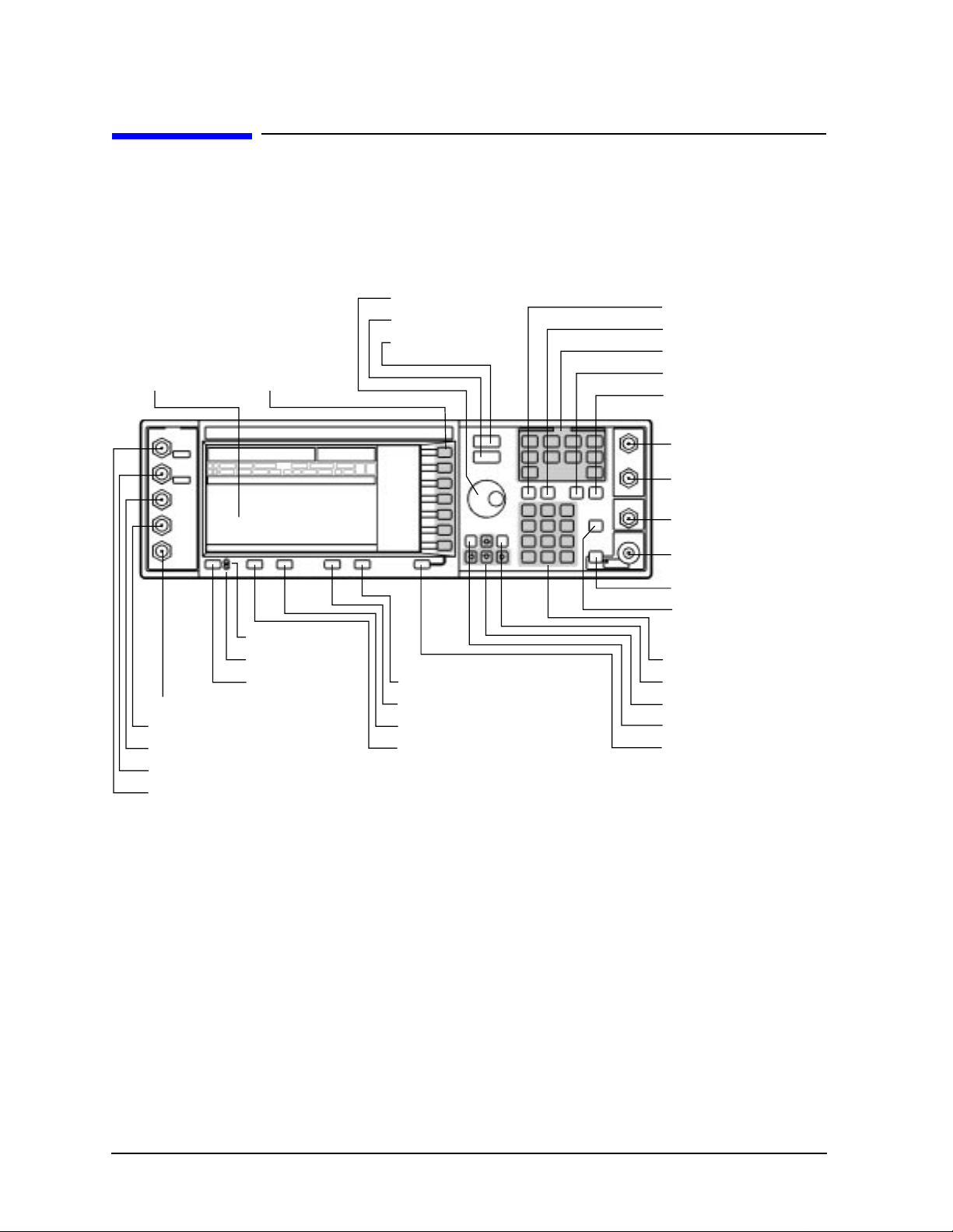
Front and Rear Panel HP ESG and HP ESG-D Series Signal Generators
r
r
Front Panel Overview
Front Panel Overview
21. Display
33. SYMBOL SYNC Input Connector
32. DATA CLOCK
31. DA T A Input Connector
19. Q INPUT Connector
20. I INPUT Connector
23. Softkeys
17. Line Power LED
16. Standby LED
18. Power Switch
24. Knob
25. Amplitude Key
26. Frequency Key
12. Display Contrast Decrease Key
13. Display Contrast Increase Key
14. Local Key
15. Preset Key
27. Save Key
30. Recall Key
28. Menu Keys
4. Trigger Key
3. Help Key
1. EXT 1 INPUT Connecto
2. EXT 2 INPUT Connecto
5. LF OUTPUT Connector
7. RF OUTPUT Connector
8. RF On/Off Key
6. Mod On/Off Key
9. Numeric Keypad
29. Incr Set Key
10. Arrow Keys
22. Hold Key
11. Return Key
4-2 User’s Guide
Page 95

HP ESG and HP ESG-D Series Signal Generators Front and Rear Panel
Front Panel Overview
1. EXT 1 INPUT Connector
This female BNC input connector accepts a 1-Vpk signal for FM, ΦM, and AM. For all these
modulations, ±1V
produces the indicated deviation or depth. When AC-coupled inputs
pk
are selected for FM, ΦM, or AM, HI/LO annunciators will light if the peak input voltage
differs from 1.0 V by more than 3%. The input impedance is 50Ω. The damage levels are
5V
and 10 Vpk. If you configure your signal generator with Option 1EM, this input is
rms
relocated to a rear panel, female BNC connector.
2. EXT 2 INPUT Connector
This female BNC input connector accepts a 1-Vpk signal for FM, ΦM, AM, and pulse
modulation. With FM, ΦM, or AM, ±1V
produces the indicated deviation or depth. With
pk
pulse modulation, +1 V is on and 0 V is off. When AC-coupled inputs are selected for FM,
ΦM, or AM, HI/LO annunciators will light if the peak input voltage differs from 1.0 V by
more than 3%. The input impedance is 50Ω. The damage levels are 5 V
and 10 Vpk. If
rms
you configure your signal generator with Option 1EM, this input is relocated to a rear
panel, female BNC connector.
3. Help Key
Press this hardkey for a short textual description of the function of the front panel
hardkeys and softkeys. Press this key again and you will be returned to normal
instrument operation.
4. Trigger Key
Press this hardkey to begin an event (such as a step or list sweep). This key must first be
selected as the method for activating an event by pressing the
T rigger Key softkey, located in
the softkey menus associated with the event
5. LF OUTPUT Connector
This female BNC connector is the output connector for modulation signals generated by
the LF (low frequency) source function generator. You can also output signals where the
frequency and shape are set by the internal source as it is being used by a modulation. F or
pulse modulation, however, the internal source is a sinewave that is later squared by the
modulator to generate the pulse squarewave.
This output is capable of driving 3.5 V
into a 50Ω load. If you configure your signal
pk
generator with Option 1EM, this input is relocated to a rear panel, female BNC connector.
6. Mod On/Off Key
This hardkey toggles all modulation signals on and off. Although you can set up and enable
various modulation states, the RF carrier is not modulated until
annunciator is always turned on in the display to indicate whether modulation is turned
on or off.
Mod On/Off is set to On. An
User’s Guide 4-3
Page 96

Front and Rear Panel HP ESG and HP ESG-D Series Signal Generators
Front Panel Overview
7. RF OUTPUT Connector
This female Type-N connector is the output connector for RF signals. The source
impedance is 50Ω. The damage levels are 50 Vdc, 50 W at ≤ 2 GHz, and 25 W at > 2 GHz
maximum. The reverse power protection circuit will trip, however, at nominally 1 watt. If
you configure your signal generator with Option 1EM, this output is relocated to a rear
panel, female Type-N connector.
8. RF On/Off Key
This hardkey toggles the RF signal on and off at the RF OUTPUT connector. An
annunciator is always turned on in the display to indicate whether RF is turned on or off.
9. Numeric Keypad
The numeric keypad consists of the digit keys (0 through 9), a decimal point key, and a
backspace key, . The backspace key has dual functions for both backspacing and for
changing the sign of a value between positive and negative. Use these keys whenever the
active function requires a value input.
10. Arrow Keys
The up and down arrow keys increase or decrease a numeric value. You can also use these
keys to scroll through displayed lists to select items. The left and right arrow keys choose
the highlighted digit in the active function display; that digit can be modified by the up
and down arrow keys or the knob. You can also use these keys in a list to select items in a
row.
11. Return Key
The Return key cancels the current active function and moves you from your current softkey
menu to the softkey menu that precedes it. It will back up through the menus of the
current hardkey until you reach the first menu of that key.
12. Display Contrast Decrease Key
Press this key and hold it down to cause the display background to darken in comparison
to the text on the display.
13. Display Contrast Increase Key
Press this key and hold it down to cause the display background to brighten in comparison
to the text on the display.
14. Local Key
Press this key to return the signal generator to local (front panel) control from remote
operation.
15. Preset Key
Press this key to set the signal generator to a known state (either the factory-defined state
or a user-defined state).
4-4 User’s Guide
Page 97

HP ESG and HP ESG-D Series Signal Generators Front and Rear Panel
Front Panel Overview
16. Standby LED
This yellow LED lights when the instrument is in standby condition. In standby, the power
switch is off but the instrument is still connected to the main power circuit by way of the
power cord.
17. Line Power LED
This green LED lights when power is cycled on to the signal generator.
18. Power Switch
Press this hardkey to turn power to the signal generator either on (green LED on) or to
standby (yellow LED on).
19. Q INPUT Connector
This connector accepts an externally supplied, analog, quadrature-phase component of I/Q
modulation. The signal level is = 0.5 V
impedance is 50Ω. The damage level is 1 V
on HP ESG-D Series Signal Generators. If you configure your instrument with
Option 1EM, this input is relocated to a rear panel, female BNC connector.
for a calibrated output level. The input
rms
. This female BNC connector is provided only
rms
20. I INPUT Connector
This connector accepts an externally supplied, analog, in-phase component of I/Q
modulation. The signal level is = 0.5 V
impedance is 50Ω. The damage level is 1 V
for a calibrated output level. The input
rms
. This female BNC connector is provided only
rms
on HP ESG-D Series Signal Generators. If you configure your instrument with
Option 1EM, this input is relocated to a rear panel, female BNC connector.
21. Display
The LCD display provides information on the current instrument state such as modulation
status, frequency and amplitude settings, status indicators, and error messages. Softkey
labels corresponding to their adjacent keys are located on the right-hand side of the
display. For details about the display, see “Display Annotation” on page 4-8.
22. Hold Key
Press this hardkey to deactivate the currently active function and blank the softkey menu.
Once
Hold is pressed, the front panel knob, the arrow keys, and the numeric keypad have
no effect. To return to normal operation, press a function or menu hardkey.
23. Softkeys
Press a softkey to activate the function indicated by the corresponding label on the display.
24. Knob
The knob increases or decreases a numeric value. Any of the values that can be set through
the numeric keypad or the step keys can also be set by the knob.
User’s Guide 4-5
Page 98

Front and Rear Panel HP ESG and HP ESG-D Series Signal Generators
Front Panel Overview
25. Amplitude Key
Press this hardkey to activate the power level amplitude function so that you can change
the amplitude of the RF output.
26. Frequency Key
Press this hardkey to activate the frequency function so that you can change the frequency
of the RF output.
27. Save Key
This hardkey lets you save up to 100 different instrument states in a combination of 100
memory registers and 10 register sequences. The number of states you can save, however,
is limited by the size of whatever else is stored in the file system.
28. Menu Keys
These hardkeys provide access to the signal generator’s primary functionality. Press these
keys for access to softkey menus where you can configure modulations, step and list
sweeps, and various frequency and power capabilities.
29. Incr Set Key
Press this hardkey to toggle between the current active function and the increment size for
that function. With increment size selected, you can change the current increment value.
30. Recall Key
This hardkey lets you restore any instrument state that you previously saved in a memory
register. You can save up to 100 different instrument states in a combination of 100
memory registers and 10 register sequences. The number of states you can save, however,
is limited by the size of whatever else is stored in the file system.
31. DATA Input Connector
The TTL/CMOS compatible DATA connector accepts an externally supplied data input for
digital modulation applications. The expected input is a TTL or CMOS signal where a
CMOS high is equivalent to a data 1 and a CMOS low is equivalent to a data 0.
The maximum input data rate is 1.152 Mb/s. The leading edges must be synchronous with
the DATA CLOCK rising edges. The data must be valid on the DATA CLOCK falling
edges. The damage levels are > +8 and < −4V.
This female BNC connector is provided on instruments with Option UN8. It is also present
but not functional on instruments with Option UND. On instruments with Option 1EM,
this input is relocated to a rear panel SMB connector.
32. DATA CLOCK Input Connector
The TTL/CMOS compatible DATA CLOCK connector accepts an externally supplied
data-clock input for digital modulation applications. The expected input is a TTL or CMOS
signal (either bit or symbol) where the rising edge is aligned with the beginning data bit.
The CMOS falling edge is used to clock the DATA and SYMBOL SYNC signals.
4-6 User’s Guide
Page 99

HP ESG and HP ESG-D Series Signal Generators Front and Rear Panel
Front Panel Overview
The maximum clock rate is 1.152 MHz. The damage levels are > +8 and < −4V.
This female BNC connector is provided on instruments with Option UN8. It is also present
but not functional on instruments with Option UND. On instruments with Option 1EM,
this input is relocated to a rear panel SMB connector.
33. SYMBOL SYNC Input Connector
The CMOS compatible SYMBOL SYNC connector accepts the digital-modulation symbol
synchronization signal from an external source. This signal synchronizes the serial
multi-bit symbol transmission. The expected signal may be continuous or a single, one-bit
wide pulse to synchronize the first bit of the first symbol. The CMOS rising edge must be
synchronous with the DATA CLOCK rising edges. The synchronization signal must be
valid on the DATA CLOCK falling edges.
The damage levels are > +8 and < −4V.
This female BNC connector is provided on instruments with Option UN8. It is also present
but not functional on instruments with Option UND. On instruments with Option 1EM,
this input is relocated to a rear panel SMB connector.
User’s Guide 4-7
Page 100

Front and Rear Panel HP ESG and HP ESG-D Series Signal Generators
Display Annotation
Display Annotation
7. Annunciators
6. Active Entry
Area
5. Text Area
1. Frequency Area
4. Error Message Area
7a. Digital Modulation
Annunciators
2. Amplitude Area
3. Softkey Labels
1. Frequency Area
The current CW frequency setting is shown in this portion of the display. Indicators are
also displayed in this area when a frequency offset or multiplier is set or if frequency
reference mode is turned on.
2. Amplitude Area
The current output power level setting is shown in this portion of the display. Indicators
are also displayed in this area when an amplitude offset is set or if amplitude reference
mode is turned on.
3. Softkey Labels
These labels define the function of the corresponding softkeys immediately to the right of
the label.
4. Error Message Area
Abbreviated error messages are reported in this space. When multiple error messages
occur, only the most recent message remains displayed. All of the reported error messages
with details can be viewed by pressing
Utility, Error Info, View Next Error Message.
4-8 User’s Guide
 Loading...