


User’s Guide
HP E4419B Power Meter
HP Part no. E4419-90006
December, 1998

© Copyright Hewlett-Packard Company
All rights reserved. Reproduction, adaptation, or translation without prior
written permission is prohibited, except as allowed under the copyright
laws.
Printed in the UK.
ii HP E4419B User’s Guide

Legal Information
Legal Information
Notice
Information contained in this document is subject to change without
notice. Hewlett-Packard makes no warranty of any kind with regard to
this material, including, but not limited to, the implied warranties of
merchantability and fitness for a particular purpose. Hewlett-Packard
shall not be liable for errors contained herein or for incidental or
consequential damages in connection with the furnishings, performance,
or use of this material. No part of this document may be photocopied,
reproduced, or translated to another language without the prior written
consent of HP.
Certification
Hewlett-Packard Company certifies that this product met its published
specifications at the time of shipment from the factory. Hewlett-Packard
further certifies that its calibration measurements are traceable to the
United States National Institute of Standards and Technology, to the
extent allowed by the Institute’s calibration facility, and to the calibration
facilities of other International Standards Organization members.
Warranty
This Hewlett-Packard instrument product is warranted against defects in
material and workmanship for a period of one year from date of shipment.
During the warranty period, Hewlett-Packard Company will at its option,
either repair or replace products which prove to be defective. For warranty
service or repair, this product must be returned to a service facility
designated by HP. Buyer shall prepay shipping charges to HP and HP
shall pay shipping charges, duties, and taxes for products returned to HP
from another country. HP warrants that its software and firmware
designated by HP for use with an instrument will execute its
programming instructions when properly installed on that instrument.
HP does not warrant that the operation of the instrument, or firmware
will be uninterrupted or error free.
HP E4419B User’s Guide iii

Legal Information
Limitation of Warranty
The foregoing warranty shall not apply to defects resulting from improper
or inadequate maintenance by Buyer, Buyer-supplied software or
interfacing, unauthorized modification or misuse, operation outside of the
environmental specifications for the product, or improper site preparation
or maintenance. NO OTHER WARRANTY IS EXPRESSED OR IMPLIED.
HP SPECIFICALLY DISCLAIMS THE IMPLIED WARRANTIES OF
MERCHANTABILITY AND FITNESS FOR A PARTICULAR PURPOSE.
Exclusive Remedies
THE REMEDIES PROVIDED HEREIN ARE BUYER’S SOLE AND
EXCLUSIVE REMEDIES. HP SHALL NOT BE LIABLE FOR ANY
DIRECT, INDIRECT, SPECIAL, INCIDENTAL, OR CONSEQUENTIAL
DAMAGES, WHETHER BASED ON CONTRACT, TORT, OR ANY
OTHER LEGAL THEORY.
iv HP E4419B User’s Guide

Equipment Operation
Equipment Operation
Warnings and Cautions
This guide uses warnings and cautions to denote hazards.
WARNING A warning calls attention to a procedure, practice or the
like, which, if not correctly performed or adhered to, could
result in injury or the loss of life. Do not proceed beyond a
warning until the indicated conditions are fully
understood and met.
Caution A caution calls attention to a procedure, practice or the like which,
if not correctly performed or adhered to, could result in damage to
or the destruction of part or all of the equipment. Do not proceed
beyond a caution until the indicated conditions are fully
understood and met.
Personal Safety Considerations
WARNING This is a Safety Class I product (provided with a protective
earthing ground incorporated in the power cord). The
mains plug shall only be inserted in a socket outlet
provided with a protective earth contact. Any interruption
of the protective conductor, inside or outside the
instrument, is likely to make the instrument dangerous.
Intentional interruption is prohibited.
If this instrument is not used as specified, the protection
provided by the equipment could be impaired. This
instrument must be used in a normal condition (in which
all means of protection are intact) only.
No operator serviceable parts inside. Refer servicing to
qualified personnel. To prevent electrical shock, do not
remove covers.
For continued protection against fire hazard, replace the
line fuse(s) only with fuses of the same type and rating (for
example, normal blow, time delay, etc.). The use of other
fuses or material is prohibited.
HP E4419B User’s Guide v

General Safety Considerations
General Safety Considerations
WARNING Before this instrument is switched on, make sure it has
been properly grounded through the protective conductor
of the ac power cable to a socket outlet provided with
protective earth contact.
Any interruption of the protective (grounding) conductor,
inside or outside the instrument, or disconnection of the
protective earth terminal can result in personal injury.
Caution Any adjustments or service procedures that require operation of
the instrument with protective covers removed should be
performed only by trained service personnel.
Markings
The CE mark shows that the product complies with
all the relevant European legal Directives (if
accompanied by a year, it signifies when the design
was proven.
GROUP 1
ISM
vi HP E4419B User’s Guide
CLASS A
This is the symbol of an Industrial Scientific and
Medical Group 1 Class A product.
The CSA mark is a registered trademark of the
Canadian Standards Association.
External Protective Earth Terminal.
While this is a Class I product, provided with a
protective earthing conductor in a power cord, an
external protective earthing terminal has also been
provided. This terminal is for use where the earthing
cannot be assured. At least an 18AWG earthing
conductor should be used in such an instance, to
ground the instrument to an assured earth terminal.

General Safety Considerations
IEC 1010-1 Compliance
This instrument has been designed and tested in accordance with IEC
Publication 61010-1 +A1:1992 Safety Requirements for Electrical
Equipment for Measurement, Control and Laboratory Use and has been
supplied in a safe condition. The instruction documentation contains
information and warnings which must be followed by the user to ensure
safe operation and to maintain the instrument in a safe condition.
Statement of Compliance
This product has been designed and tested for compliance with IEC 60529
(1989) Degrees of Protection Provided by Enclosures (IP Code). Level IPx4
is attained if, and only if, the carry case( part number HP 34141A) is
fitted.
User Environment
This product is designed for use in a sheltered environment (avoiding
extreme weather conditions) in accordance with Pollution Degree 3
defined in IEC 60664-1, with the carry case ( part number HP 34141A)
fitted over the instrument.
The product is suitable for indoor use only, when this carry case is not
fitted.
Installation Instructions
To avoid unnecessary over-temperature conditions, while this carry case is
fitted do not apply an ac mains supply voltage, only operate your
HP E4419B from the battery pack.
HP E4419B User’s Guide vii

Regulatory Information
Regulatory Information
Sound Emission
Herstellerbescheinigung
Diese Information steht im Zusammenhang mit den Anforderungen der
Maschinenlarminformationsverordnung vom 18 Januar 1991.
• Sound Pressure LpA < 70 dB.
• Am Arbeitsplatz.
• Normaler Betrieb.
• Nach DIN 45635 T. 19 (Typprufung).
Manufacturers Declaration
This statement is provided to comply with the requirements of the
German Sound DIN 45635 T. 19 (Typprufung).
• Sound Pressure LpA < 70 dB.
• At operator position.
• Normal operation.
• According to ISO 7779 (Type Test).
Australian EMC Regulations
The C-Tick mark is a registered trademark of the Spectrum Management
Agency of Australia. This signifies compliance with the Australian EMC
Framework Regulations under the terms of the Radiocommunications Act
of 1992.
viii HP E4419B User’s Guide

Regulatory Information
Declaration of Conformity
according to ISO/IEC Guide 22 and EN45014
Manufacturer’s Name: Hewlett Packard Ltd.
Manufacturer's Address:
Declares that the product
Product Name
:
Model Numbers:
Product Options:
Conforms with the protection requirements of European Council Directive 89/336/EEC on the approximation
of the laws of the member states relating to electromagnetic compatibility.
Against EMC test specifications EN 55011:1991 (Group 1, Class A) and EN 50082-1:1992
As Detailed in:
Assessed by:
Technical Report Number:6893/2200/CBR, dated 23 September 1997
Supplementary Information: The product conforms to the following safety standards
The product herewith complies with the requirements of the Low Voltage Directive 73/23/EEC, and carries the
CE-marking accordingly. This product is also designed to meet IPx4 in accordance with IEC 60529:1989 / EN
60529:1992.
South Queensferry, Scotland 22 October 1998
Queensferry Microwave Division
South Queensferry
West Lothian, EH30 9TG
Scotland, United Kingdom
Dual Channel Power Meter
HP E4419B
This declaration covers all options of the above products as detailed in
TCF A-5951-9852-02
Electromagnetic Compatibility (EMC)
Technical Construction File (TCF) No. A-5951-9852-01
Dti Appointed Competent Body
EMC Test Centre,
GEC-Marconi Avionics Ltd.,
Maxwell Building,
Donibristle Industrial Park,
KY11 5LB
Scotland, United Kingdom
EN61010-1 (1993) / IEC 1010-1 (1990) + A1 (1992)
CSA-C22.2 No. 1010.1-92
EN60825-1 (1994) / IEC 825-1 (1993)
Location Date
Europe Contact:
Your local Hewlett-Packard Sales and Service Office or Hewlett-Packard GmbH, Department 2Q /
Standards Europe, Herrenberger Strasse 130, D7030 Boblinger (Fax; +49-7031-143143).
R.M. Evans / Quality Manager
HP E4419B User’s Guide ix

List of Related Publications
List of Related Publications
The HP E4419B User’s Guide is also available in the following languages:
• English Language User’s Guide - Standard
• German Language User’s Guide - Option ABD
• Spanish Language User’s Guide - Option ABE
• French Language User’s Guide - Option ABF
• Italian Language User’s Guide - Option ABZ
• Japanese Language User’s Guide - Option ABJ
HP E4418B/E4419B Programming Guide is shipped as standard.
HP E4418B/E4419B Service Guide is available by ordering Option 915.
HP E4418B/E4419B CLIPs (Component Location and Information Pack)
is available by ordering E4418-90031.
Useful information on SCPI (Standard Commands for Programmable
Instruments) can be found in:
• A Beginner’s Guide to SCPI, which is available by ordering
HP Part Number 5010-7166.
• The SCPI reference manuals which are available from:
SCPI Consortium,
8380 Hercules Drive, Suite P3,
La Mesa, CA 91942, USA.
Telephone: 619-697-4301
Fax: 619-697-5955
x HP E4419B User’s Guide

HP E4419B Options
HP E4419B Options
The HP E4419B power meters have the following options available:
• Option 001, supplies an internal rechargeable battery providing
full instrument functionality when access to an ac power outlet is
not available.
• Option 002, supplies parallel rear panel sensor input(s). The
power reference oscillator output is on the front panel.
• Option 003, supplies parallel rear panel sensor input(s). The
power reference oscillator output is also on the rear panel.
• Option 004, deletes the HP 11730A sensor cable(s) provided.
• Option 0BO, deletes manual set.
• Option 908, provides rackmount kit for one instrument.
• Option 909, provides rackmount kit for two instruments.
• Option 915, provides the HP E4418B/E4419B Service Guide.
• Option 916, provides an additional HP E4419B User’s Guide and
HP E4418B/E4419B Programming Guide.
• Option 1BN, provides MIL-STD 45662A, Certificate of
Calibration.
• Option 1BP, provides MIL-STD-45662A, Certificate of Calibration
and data.
Available Accessories
• HP 34161A Accessory Pouch
• HP 34141A Yellow soft carry/operating case
• HP 34131A basic instrument transit case
• HP E9287A Spare battery pack - for instruments fitted with
option 001 only
• HP 34397A 12 Vdc to 115 Vac inverter (Option 0E3 230 V)
• The following HP power sensor cables are available:
■ HP 11730A 1.5 m (7.5 ft)
■ HP 11730B 3 m (10 ft)
■ HP 11730C 6.1 m (20 ft)
■ HP 11730D 15.2 m (50 ft)
■ HP 11730E 30.5 m (100 ft)
■ HP 11730F 61 m (200 ft)
HP E4419B User’s Guide xi

About this Guide
About this Guide
Chapter 1: Getting Started
This chapter prepares the power meter for use and helps you to get
familiar with a few of the front panel features.
Chapter 2: Power Meter Operation
This chapter gives a detailed description of the capabilities and operation
of the power meter. You will find this chapter useful when you are
operating the power meter from the front panel.
Chapter 3: Menu Map Reference
This chapter details diagrammatically the menu maps for the power
meter. It also gives a description of all the power meter’s keys.
Chapter 4: Error Messages
This chapter lists the error messages that may appear as you are working
with the power meter. Each description contains information to help you
diagnose and solve the problem.
Chapter 5: Specifications
This chapter lists the power meter’s specifications and describes how to
interpret these specifications.
xii HP E4419B User’s Guide

Table of Contents
Legal Information ........................................................................iii
Notice .....................................................................................iii
Certification ...........................................................................iii
Warranty................................................................................iii
Limitation of Warranty......................................................... iv
Exclusive Remedies............................................................... iv
Equipment Operation ................................................................... v
Personal Safety Considerations............................................. v
General Safety Considerations.................................................... vi
Markings................................................................................ vi
IEC 1010-1 Compliance........................................................ vii
Statement of Compliance ..................................................... vii
User Environment................................................................ vii
Installation Instructions ...................................................... vii
Regulatory Information ............................................................. viii
Sound Emission ................................................................... viii
Australian EMC Regulations.............................................. viii
List of Related Publications ......................................................... x
HP E4418B Options..................................................................... xi
Available Accessories ............................................................ xi
About this Guide ......................................................................... xii
Page
Getting Started .................................................................................... 1-1
Introduction................................................................................... 1-2
Turning On the Power Meter ....................................................... 1-3
The Front Panel at a Glance ........................................................ 1-4
The Display Layout....................................................................... 1-7
Selecting Your Display Layout .............................................. 1-11
Window Symbols........................................................................... 1-14
Warning Symbol ..................................................................... 1-14
Confirmation Window ............................................................ 1-14
Wait Symbol............................................................................ 1-14
1 of N Entry Window.............................................................. 1-15
Numeric or Alphanumeric Entry Window ............................ 1-15
HP E4419B User’s Guide Contents-1

The Rear Panel at a Glance.......................................................... 1-16
Adjusting the Carrying Handle.................................................... 1-18
Rack Mounting the Power Meter ................................................. 1-19
Power Meter Operation ..................................................................... 2-1
Introduction................................................................................... 2-2
Battery Operation (Option 001) ................................................... 2-3
General Information............................................................... 2-3
Running Time......................................................................... 2-3
Charging Times ...................................................................... 2-4
Backlight................................................................................. 2-4
Battery Removal/Replacement .............................................. 2-5
Zeroing and Calibrating the Power Meter................................... 2-7
Zeroing the Power Meter........................................................ 2-7
Zero/Cal Lockout..................................................................... 2-7
Calibrating the Power Meter ................................................. 2-8
Calibration Procedure Using HP E-Series
Power Sensors......................................................................... 2-8
Calibration Procedure using HP 8480 Series
Power Sensors......................................................................... 2-9
Zeroing and Calibrating Using TTL Inputs.......................... 2-12
Making Measurements with the HP E-Series
Power Sensors ............................................................................... 2-15
Procedure ................................................................................ 2-15
Making Measurements with the HP 8480 Series
Power Sensors ............................................................................... 2-17
Procedure ................................................................................ 2-17
Making Measurements using Sensor Calibration Tables........... 2-19
Selecting a Sensor Calibration Table .................................... 2-19
Making the Measurement...................................................... 2-20
Editing Sensor Calibration Tables ........................................ 2-21
Making Measurements using Frequency Dependent
Offset Tables ................................................................................. 2-27
Selecting a Frequency Dependent Offset Table.................... 2-27
Making the Measurement...................................................... 2-28
Editing Frequency Dependent Offset Tables........................ 2-29
Setting the Units of Measurement............................................... 2-32
Selecting Units of Measurement from the Softkeys ................... 2-33
Making Relative Measurements .................................................. 2-34
Procedure ................................................................................ 2-34
Setting the Resolution .................................................................. 2-35
Setting Offsets............................................................................... 2-36
Setting Channel Offsets......................................................... 2-36
Contents-2 HP E4419B User’s Guide

Setting Display Offsets .......................................................... 2-36
Setting Averaging ......................................................................... 2-38
Step Detection......................................................................... 2-39
Measuring Pulsed Signals............................................................ 2-41
Setting Measurement Limits ....................................................... 2-43
Setting Channel Limits.......................................................... 2-43
Setting Window Limits .......................................................... 2-44
Checking for Limit Failures................................................... 2-47
Selecting a Digital or Analog Display.......................................... 2-49
Setting the Range ......................................................................... 2-52
Configuring the Remote Interface................................................ 2-53
HP-IB ...................................................................................... 2-53
RS232/RS422 .......................................................................... 2-54
Remote Interface Overview.................................................... 2-56
Programming Language Selection ........................................ 2-58
Recorder Output............................................................................ 2-59
Leveling a Source Output ...................................................... 2-60
Saving and Recalling Power Meter Configurations .................... 2-61
How Measurements are Calculated............................................. 2-63
Presetting the Power Meter ......................................................... 2-64
Preset Conditions ................................................................... 2-64
Self Test......................................................................................... 2-66
Power On Self Test................................................................. 2-66
Front Panel Selection of Self Tests........................................ 2-67
Remote Testing....................................................................... 2-69
Test Descriptions.................................................................... 2-70
Operator Maintenance.................................................................. 2-73
Replacing the Power Line Fuse ............................................. 2-73
Contacting Hewlett-Packard........................................................ 2-74
Before calling Hewlett-Packard............................................. 2-74
Check the Basics..................................................................... 2-75
Instrument serial numbers.................................................... 2-75
Sales and Service Offices ....................................................... 2-77
Returning Your Power Meter for Service.............................. 2-80
Menu Reference................................................................................... 3-1
Introduction................................................................................... 3-2
The Front Panel Menu Maps ....................................................... 3-3
dBm/W Menu .......................................................................... 3-3
Frequency/Cal Fac Menu ....................................................... 3-4
Meas Setup Menu................................................................... 3-5
Rel/Offset Menu...................................................................... 3-6
Save/Recall Menu ................................................................... 3-6
HP E4419B User’s Guide Contents-3

System Inputs Menu (1 of 4).................................................. 3-7
System Inputs Menu (2 of 4).................................................. 3-8
System Inputs Menu (3 of 4).................................................. 3-9
System Inputs Menu (4 of 4).................................................. 3-10
Zero/Cal Menu ........................................................................ 3-11
Front Panel Menu Reference........................................................ 3-12
Diagrammatical Hardkeys..................................................... 3-36
Error Messages .................................................................................... 4-1
Introduction................................................................................... 4-2
Error Messages ............................................................................. 4-4
Specifications....................................................................................... 5-1
Introduction................................................................................... 5-2
Power Meter Specifications .......................................................... 5-3
Meter....................................................................................... 5-3
Accuracy.................................................................................. 5-4
Power Reference ..................................................................... 5-5
Power Meter Supplemental Characteristics ............................... 5-6
Power Reference ..................................................................... 5-6
Measurement Speed............................................................... 5-6
Zero Drift of Sensors .............................................................. 5-7
Measurement Noise................................................................ 5-7
Settling Time .......................................................................... 5-9
Power Sensor Specifications .................................................. 5-12
Battery Option 001 Operational Characteristics ........................ 5-13
General Characteristics................................................................ 5-14
Rear Panel Connectors........................................................... 5-14
Environmental Characteristics.................................................... 5-15
General Conditions................................................................. 5-15
Operating Environment......................................................... 5-15
Storage Conditions ................................................................. 5-15
General .......................................................................................... 5-16
Dimensions ............................................................................. 5-16
Weight..................................................................................... 5-16
Safety ...................................................................................... 5-16
Remote Programming ............................................................ 5-16
Non-Volatile Memory ............................................................. 5-17
Contents-4 HP E4419B User’s Guide

List of Figures
Page
2-1 Battery Status............................................................................ 2-4
2-2 Battery Removal/Replacement.................................................. 2-6
2-3 Rmt I/O Port TTL Inputs .......................................................... 2-12
2-4 “Sensor Tbls” Screen.................................................................. 2-20
2-5 “Edit Cal” Screen ....................................................................... 2-21
2-6 “Offset Tbls” Screen................................................................... 2-28
2-7 “Edit” Screen.............................................................................. 2-29
2-8 Effect of Offsets on a Channel Measurement........................... 2-37
2-9 Averaged Readings .................................................................... 2-39
2-10 Pulsed Signal ............................................................................. 2-41
2-11 Limits Checking Application..................................................... 2-44
2-12 Limits Checking Results ........................................................... 2-44
2-13 Remote I/O TTL Outputs........................................................... 2-46
2-14 Pass/Fail Limit Indicators......................................................... 2-48
2-15 Digital Display........................................................................... 2-49
2-16 Analog Display........................................................................... 2-49
2-17 Digital and Analog Display ....................................................... 2-49
2-18 RS232/422 Pin Assignment....................................................... 2-54
2-19 Interface Overview Examples ................................................... 2-57
2-20 Test Setup for Recording Swept Measurements...................... 2-59
2-21 “Save/Recall” Screen.................................................................. 2-62
2-22 How Measurements are Calculated.......................................... 2-63
2-23 Replacing the Fuse .................................................................... 2-73
4-1 Error Annunciator Position....................................................... 4-2
HP E4419B User’s Guide Contents-5

Contents-6 HP E4419B User’s Guide

List of Tables
Page
2-1 Connecting the HP 8480 Series Power Sensors
During Calibration .................................................................... 2-11
2-2 TTL Inputs Control Logic.......................................................... 2-12
2-3 TTL Input Timing Diagram 1 ................................................... 2-13
2-4 TTL Inputs Timing Diagram 2 ................................................. 2-14
2-5 Measurement Units................................................................... 2-32
2-6 Range of Values for Window Limits ......................................... 2-45
5-1 Zero Set Specifications .............................................................. 5-4
5-2 Noise Multiplier......................................................................... 5-7
5-3 Power Sensor Specifications...................................................... 5-8
5-4 Settling Time ............................................................................. 5-9
5-5 Settling Time ............................................................................. 5-10
HP E4419B User’s Guide Contents-7

Contents-8 HP E4419B User’s Guide

1
Getting Started

Getting Started
Introduction
Introduction
One of the first things you will want to do with your power meter is to
switch it on and become acquainted with its front panel. The sections in
this chapter prepare the power meter for use and help you get familiar
with some of the front panel operations.
The front panel consists of both hardkeys and softkeys which allow you to
select various functions and operations. When some hardkeys are selected
the corresponding softkey labels are displayed on the power meter display.
If you are using the power meter remotely refer to the HP E4418B/4419B
Programming Guide for remote operating details.
1-2 HP E4419B User’s Guide

Getting Started
Turning On the Power Meter
Turning On the Power Meter
The following steps show you how to turn on the power meter and verify
that it is operating correctly.
1. Connect the power cord and turn on the power meter.
The front panel display and the green power LED light up when
the power meter is switched on. The power meter performs it’s
power on self test. If the self test is not successful the error
annunciator turns on. If this occurs contact your Hewlett-Packard
Sales and Service office for instructions on returning the power
meter to Hewlett-Packard for service.
Caution This instrument is designed for use in Installation Category II and
Pollution Degree 2 per IEC 1010 and 664 respectively.
Caution This instrument has an autoranging line voltage input, be sure
the supply voltage is within the range of 85 to 264 Vac.
Note If the power meter has been stored at extremely low temperatures
outwith the operating range of the power meter, the display may
take a few minutes to operate.
2. Set the display contrast if required.
The display contrast is adjusted by pressing and . If
these softkeys are not displayed press repeatedly until they
Prev
appear.
3. Connect the power sensors.
Connect one end of each of the sensor cables to the power meter’s
channel inputs and the other ends to the power sensors.
4. Making a measurement.
A minimum warm up time of 30 minutes is recommended before
accurate measurements can be made.
Prior to making your first measurement you must zero and
calibrate the sensor and meter combination. Refer to Chapter 2 for
further information if you are not familiar with zeroing,
calibrating or making measurements with a power meter.
HP E4419B User’s Guide 1-3
Getting Started
The Front Panel at a Glance
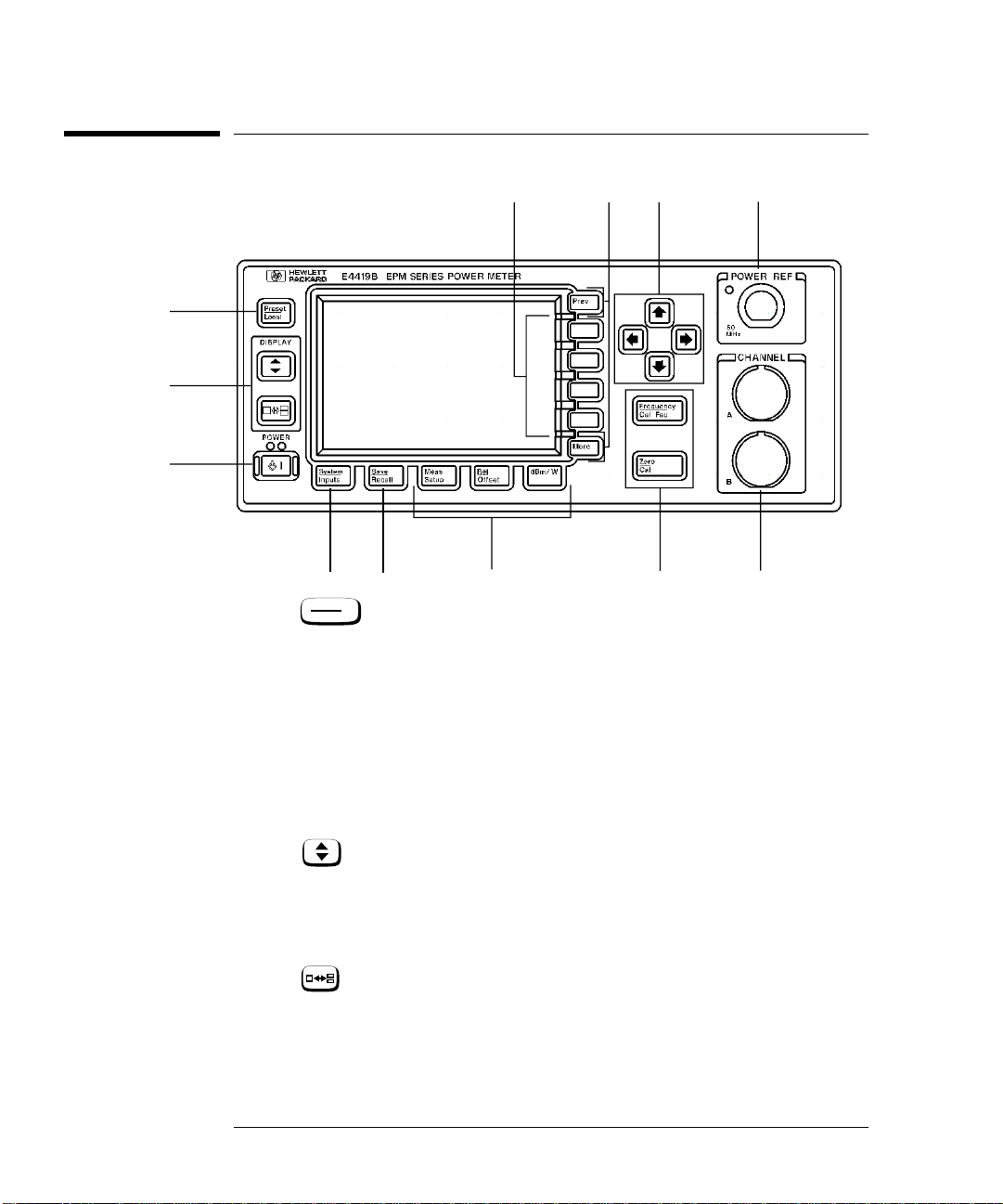
The Front Panel at a Glance
101112
1
2
3
9
8
1.
4
Preset
Local
5
6
7
This hardkey allows you to preset the power meter if you are
currently working in local mode (that is, front panel operation). In
local mode a confirmation pop up window is displayed prior to a
preset being carried out. However, if you are in remote mode (that
is, HP-IB, RS232 or RS422 operation), then pressing this hardkey
places the power meter in local mode provided local lock out (LLO)
is not enabled.
2. Hardkeys relating to the display layout.
This hardkey allows you to select the upper or lower
measurement window on the power meter’s display. The window
which is selected is highlighted by a shadowed box. Any
measurement setup you create is implemented in the selected
window.
This hardkey allows you to choose either a one or a two
window display.
1-4 HP E4419B User’s Guide

Getting Started
The Front Panel at a Glance
3.
This hardkey switches the power meter between on and standby.
When the power meter is switched to standby (that is, when this
hardkey has not been selected but the line power is connected to
the instrument) the red LED is lit. When the power meter is
switched on the green LED is lit.
Option 001 Battery: On standby with the battery installed and the
ac power source disconnected the red LED is off.
4. “System/Inputs” hardkey with softkey menu.
System
The hardkey allows access to softkey menus which affect
Inputs
the general power meter system setup, (for example the HP-IB
address) and also to softkey menus which effect the setup of the
channel inputs. Refer to Chapter 3 for further information about
this hardkey and it’s softkey menu.
Save
5.
Recall
This hardkey is the only one that is completely dedicated to the
control of the power meter as a system. The only other hardkey
which affects system parameters is the hardkey. Refer to
System
Inputs
Chapter 3 for further information about this hardkey and it’s
softkey menu.
6. Dedicated “Window” hardkeys with softkey menus.
Meas
Setup
Rel
,,
Offset
dBm/W
These hardkeys allow access to softkey menus which affect the
setup of the measurement windows. Refer to Chapter 3 for further
information about these hardkeys and their softkey menus.
7. Dedicated “Channel” hardkeys with softkey menus.
Frequency
Cal Fac
Zero
,
Cal
These hardkeys allow access to softkey menus which affect the
measurement channel. Refer to Chapter 3 for further information
about these hardkeys and their softkey menus.
8. Channel Inputs.
The HP E4419B has two sensor inputs. Power meters configured
with options 002 or 003 have the sensor inputs on the rear panel
and the front panel.
HP E4419B User’s Guide 1-5

Getting Started
The Front Panel at a Glance
9. POWER REF Output.
The power reference output is a 50 Ω type N connector. The output
signal of 1 mW at 50 MHz is used for calibrating the sensor and
meter combination. Power meters configured with option 003 have
the power reference on the rear panel.
10. Arrow hardkeys.
, , and hardkeys allow you to move the
position of the cursor, select fields for editing, and edit
alphanumeric characters. Refer to Chapter 3 for further
information.
11. Menu related hardkeys.
More
This hardkey allows you to move through all pages of a
menu. The bottom right of the power meter display indicates the
number of pages in the menu. For example, if “1 of 2” is
displayed, pressing moves you to “2 of 2”. Pressing
again moves you back to “1 of 2”.
Prev
This hardkey allows you to move back one level in the
softkey menu. Repeatedly pressing accesses a menu which
allows you to increase and decrease the display contrast.
More More
Prev
12. Softkeys.
These four keys are used to make a selection from the menus.
1-6 HP E4419B User’s Guide

Getting Started
The Display Layout
The Display Layout
The following figure details the display layout when two measurement
windows are displayed, one analog and one digital. However it is possible
using the key to display just one measurement window.
15
1
2
3
4
5
6
1. The status reporting line displays five fields, three associated with
either HP-IB, RS232 or RS422 status and two associated with
error and warning conditions. The first field displays either “RMT”
(remote, HP-IB, RS232 or RS422 operation) or “LCL” (local, front
panel operation).
For HP-IB operation, the second field displays “TLK” if the power
meter is addressed to talk or “LSN” if it is addressed to listen. The
third field indicates an “SRQ” (service request).
14
10111213
9
7
8
For RS232 and RS422 operation, the second field displays “RX”
when data is being received. The third field displays “TX” when the
power meter is transmitting data.
The fourth field indicates “ERR” for any error conditions. The last
field is used to report error and warning messages.
2. This field displays the channel setup being measured, either A, B,
A/B, B/A, A-B or B-A.
3. The measurement data is displayed in either one or two
rectangular windows depending on the setting of . Pressing
HP E4419B User’s Guide 1-7

Getting Started
The Display Layout
allows you to toggle between a one or two window display.
When two windows are displayed and this hardkey is pressed the
single window then displayed is the one which was previously
highlighted with the shadowed box. On the two window display
the measurement setup menus work on the window which is
shadowed.
4. This is the measurement result field.
5. This field displays the units of measurement, either dBm, dB,
Watts or %.
6. This window is configured to show an analog meter which displays
the measurement result and the meter scaling.
7. This field displays the number of pages in the current softkey
menu. For example, “1 of 2” indicates that there are two pages of
softkeys and you are on the first page. Pressing moves you
More
to page “2 of 2”.
8. Any softkeys available are displayed in these four fields.
9. This field displays the title of the menu. For example, when the
power meter is initially switched on the “Contrast” menu is
displayed, and, if you press “Zero/Cal” is displayed.
Zero
Cal
10. This field indicates if the measurement result is outwith the upper
or lower limits set. If the measurement is within the limits this
field is empty. If the measurement result is less than the minimum
limit set, “Undr Lmt” is displayed. If the measurement result is
more than the maximum limit set, “Over Lmt” is displayed. Refer
to “Setting Measurement Limits”, on page 2-43 for further
information.
11. This field displays “Rel” if relative mode is on. Refer to “Making
Relative Measurements”, on page 2-34 for further information.
12. This field displays “Ofs” if an offset is set. Refer to “Setting
Offsets”, on page 2-36 for further information.
13. This field displays “Rng Hld” if a range is selected. Refer to
“Setting the Range”, on page 2-52 for further information.
14. This field displays “Dty Cyc” if a duty cycle is set. This allows you
to measure the power of a pulsed signal. Refer to “Measuring
Pulsed Signals”, on page 2-41 for further information.
15. Theinformation in this field is displayed on two lines and depends
on thecombination of sensor type, sensor calibration table and
frequency dependent offset table currently selected. Table 1-1
shows all the possible combinations for the two lines of the display.
Find the table entry which matches your display and use the
1-8 HP E4419B User’s Guide

Getting Started
The Display Layout
reference number in the left-hand column to look up Table 1-2 for
the combination of sensor type and correction being applied to the
current measurement.
For example, the display shows:
50MHz
(10,C)
This is equivalent to reference number 4 in Table 1-1 and when
looked up in Table 1-2 shows that:
• the sensor type is 8480 series
• a sensor calibration table is selected (10)
• a frequency dependent offset table is selected(C).
Table 1-1
Reference
Number
1
2
3
4
5
6
Where “y” is the frequency multiplier (M or G), “nn” is the
sensor calibration table number and “a” is the frequency
dependent offset table letter.
Upper
Display Line
Lower
Display Line
CF:xxx.x%
CF:xxx.x% xxx.xyHz(a)
xxx.xyHz (nn)
xxx.xyHz (nn,a)
xxx.xyHz
xxx.xyHz (a)
HP E4419B User’s Guide 1-9

Getting Started
The Display Layout
Table 1-2
Reference
Number
1
2
3
4
5
6
Sensor
Series
8480
Series
Sensors
E-Series
Sensors
Sensor
Correction
Directly entered
Calibration Factor
Frequency dependent
- from selected sensor
calibration table
Frequency dependent
- downloaded directly
from sensor
Frequency Dependent
Offset Correction
None
From offset table
None
From offset table
None
From offset table
1-10 HP E4419B User’s Guide

Getting Started
The Display Layout
Selecting Your Display Layout
Your power meter display is extremely flexible. It can be used to display a
variety of different measurements and windows depending on your needs.
The following diagram details the various options available to you.
Display
Select using
One Window
Measurement Type
A, B, A/B, B/A,
A-B, B-A
Digital
Display
Select using
Meas
, Input Select
Setup
Select using
Meas
, Display Format
Setup
Analog
Display
Upper
Window
Measurement Type
A, B, A/B, B/A,
A-B, B-A
Meas
Setup
Digital
Display
Analog
Display
Two Windows
Select using
Select using
Meas
, Input Select
Setup
Select using
, Display Format
Lower
Window
Measurement Type
A, B, A/B, B/A,
A-B, B-A
Digital
Display
Analog
Display
HP E4419B User’s Guide 1-11

Getting Started
The Display Layout
Display Tutorial
If you wish to experiment with the display layout before you move on to
make measurements, the following procedure guides you through a few of
the display setups you can choose.
1.Press , .
Preset
Local
Notice that the upper window is the
one which is highlighted by the dark
box.
2.Press . The display remains the
same apart from the fact that it is now
the lower window that is highlighted
by the shadowed box.
Confirm
3.Press , ,
Meas
Setup
Meter Dgtl Anlg
Display Format
(Anlg should be
highlighted). The display now shows
one analog and one digital window.
4.Press . The display now only
shows one window. This is the analog
window which was selected in the
previous step.
5.Press . The display now shows
only the digital window.
1-12 HP E4419B User’s Guide

6. Press . The display now shows
A/B
both an analog and digital window.
Getting Started
The Display Layout
7. Press , , .
Meas
Setup
Input Select B/A
Notice that the upper window is now
set up to make a channel B over
channel A ratio measurement.
8. Press to select the lower window.
Press . Notice that the lower
window is now set up to make a
channel A over channel B ratio
measurement.
HP E4419B User’s Guide 1-13

Getting Started
Window Symbols
Window Symbols
There are a number of different graphic symbols and pop up windows that
can occur on the power meter display. These can occur for a variety of
reasons such as when:
• an error or warning occurs.
• a confirmation is required.
• you are required to wait while the power meter carries out a
procedure.
• you are required to select an entry from a list.
• you are required to enter an alphanumeric value.
Warning Symbol
The warning symbol is displayed either directly in the
measurement window or in a pop up window when such
an event occurs. A pop up window is displayed for
approximately two seconds. The text in the pop up
window gives details of the warning type. This symbol
may also appear on a measurement window, for example,
to indicate that a power sensor is not connected.
Confirmation Window
This pop up window is displayed when
you are required to press to
verify your previous selection. For
example, prior to a preset being
carried out.
Confirm
Wait Symbol
The wait symbol is displayed when the power meter is carrying
out a procedure but no action is required from you. The symbol
may appear directly in the measurement window or in a pop up
window. It may appear, for example, during, zeroing or
calibration.
1-14 HP E4419B User’s Guide

1 of N Entry Window
This pop up window is displayed when
you are required to select an entry using
and from the list.
Numeric or Alphanumeric Entry Window
This pop up window is displayed when
you are required to modify numeric or
alphanumeric data. The and
keys move the position of the cursor.
The and keys increment and
decrement the alphanumeric digit on
which the cursor is currently
positioned.
Getting Started
Window Symbols
HP E4419B User’s Guide 1-15

Getting Started
The Rear Panel at a Glance
The Rear Panel at a Glance
134
1. Channel A (Option 002 or 003 only)
2. Channel B (Option 002 or 003 only)
3. Power Ref (Option 003 only)
The power reference output is a 50 Ω type N connector. The output
signal is used for calibrating the sensor meter combination.
4. Recorder Outputs
These outputs produces a dc voltage that corresponds to the power
level of the channel input. Refer to “Recorder Output”, on
page 2-59 for further information.
10 9
2
78
11
5
6
5. Power socket
This power meter has an auto configuring power supply. This
allows it to operate over a range of voltages without manually
being set to a certain voltage.
6. Fuse
An F3.15AH fuse is installed for all voltage supplies.
7. HP-IB
This connector allows the power meter to be controlled remotely
using the Hewlett-Packard Interface Bus.
8. RS232/422
1-16 HP E4419B User’s Guide

Getting Started
The Rear Panel at a Glance
This connector allows the power meter to be controlled remotely
using either the RS232 or RS422 serial interface standards.
9. Serial Label
Each power meter has it’s own individual identification number.
Refer to “Instrument serial numbers”, on page 2-75 for further
information.
10. Rmt I/O
This connector is an RJ-45 series shielded modular jack assembly.
It provides a TTL logic level output when a measurement exceeds
a predetermined limit. TTL inputs are also provided to initiate
zero and calibration cycles.
11. Ground Connector
Binding post, accepts 4 mm plug or bare-wire connection.
HP E4419B User’s Guide 1-17

Getting Started
Adjusting the Carrying Handle
Adjusting the Carrying Handle
To adjust the position, grasp the handle by the sides and pull outward.
Rotate the handle to the desired position.
Bench top viewing positions Carrying position
1-18 HP E4419B User’s Guide

Getting Started
Rack Mounting the Power Meter
Rack Mounting the Power Meter
You can mount the power meter in a standard 19 inch rack cabinet using
one of three optional kits. Instructions and mounting hardware are
included with each rack mounting kit. Any HP System II instrument can
be rack mounted beside the HP E4419B power meter.
To rack mount the power meter:
1. Remove the handle by rotating it to the vertical position and
pulling the ends outward
2. Remove the rubber bumper by stretching a corner and sliding it
off.
Front
HP E4419B User’s Guide 1-19
Rear (bottom view)

Getting Started
Rack Mounting the Power Meter
To rack mount a single instrument, order option 908, or adapter kit
5063-9240.
To rack mount two instruments side by side, order option 909, or lock-link
kit 5061-9694 and flange kit 5063-9212.
To install one or two instruments in a sliding support shelf, order shelf
5063-9255, and slide kit 1494-0015 (for a single instrument, also order
filler panel 5002-3999).
1-20 HP E4419B User’s Guide

2
Power Meter Operation

Power Meter Operation
Introduction
Introduction
This chapter describes the parameters which configure the power meter to
make measurements and help you determine settings to optimize
performance. This chapter contains the following sections:
• “Battery Operation (Option 001)”, on page 2-3
• “Zeroing and Calibrating the Power Meter”, on page 2-7.
• “Calibrating the Power Meter”, on page 2-8.
• “Making Measurements with the HP E-Series Power Sensors”, on
page 2-15.
• “Making Measurements with the HP 8480 Series Power Sensors”,
on page 2-17.
• “Making Measurements using Sensor Calibration Tables”, on
page 2-19.
• “Making Measurements using Frequency Dependent Offset
Tables”, on page 2-27
• “Setting the Units of Measurement”, on page 2-32.
• “Selecting Units of Measurement from the Softkeys”, on page 2-33.
• “Making Relative Measurements”, on page 2-34.
• “Setting the Resolution”, on page 2-35.
• “Setting Offsets”, on page 2-36.
• “Setting Averaging”, on page 2-38.
• “Measuring Pulsed Signals”, on page 2-41.
• “Setting Measurement Limits”, on page 2-43.
• “Channel Measurements”, on page 2-52.
• “Making Difference Measurements”, on page 2-53.
• “Making Ratio Measurements”, on page 2-54.
• “Selecting a Digital or Analog Display”, on page 2-49.
• “Setting the Range”, on page 2-52.
• “Configuring the Remote Interface”, on page 2-53.
• “Recorder Output”, on page 2-59.
• “Saving and Recalling Power Meter Configurations”, on page 2-61.
• “How Measurements are Calculated”, on page 2-63
• “Presetting the Power Meter”, on page 2-64.
• “Self Test”, on page 2-66.
• “Operator Maintenance”, on page 2-73.
• “Contacting Hewlett-Packard”, on page 2-74.
2-2 HP E4419B User’s Guide

Power Meter Operation
Battery Operation (Option 001)
Battery Operation (Option 001)
The battery option (001) allows the power meter to be used in operating
environments where there is no convenient access to an ac power source.
General Information
With the battery option installed and the power meter connected to an ac
power source, the meter operates from the ac source and the battery runs
in a controlled charge mode.
If the meter is powered up under battery power, or if ac power is lost while
connected to an ac source, a pop up window displays the message
“Running Under Battery Power”. When this screen is visible the backlight
mode (see “Backlight”, on page 2-4) is over-ridden and the backlight is on
continuously. Pressing the softkey returns the display to the
previous screen.
Carry Case
Continue
A soft carry/operating case is available which makes it easy to transport
and operate your power meter in installation and maintenance
environments. To obtain a carry case order HP part number 34141A.
Caution Do not attempt to recharge the power meter or operate the power
meter from an ac power source while it is contained in the carry
case.
Running Time
A fully charged battery will typically allow the power meter to be used
continuously for up to 3 hours with the backlight off and 2 hours with the
backlight on.
Battery Status
You can check the status of the battery by pressing , ,
Service
More
, , . The Battery Status display (Figure 2-1 )
Battery
System
Inputs
shows the charge condition of the battery represented on an analog meter
scale. Below the analog scale is a message indicating the estimated power
meter running time under battery operation with the present charge level.
More
HP E4419B User’s Guide 2-3

Power Meter Operation
Battery Operation (Option 001)
Running time can be increased by operating the power meter with the
display backlight turned off (see “Backlight”, on page 2-4 ).
Figure 2-1: Battery Status
When the power meter is running on battery power and there are less
than 10 minutes of run-time remaining, the message “Battery Low”
appears at the top of the screen. In addition, a pop up window appears
every minute with the message “Battery Power Low”.
Charging Times
The battery charges automatically when the power meter is connected to
an ac source. From an empty state the battery is fully charged in less than
2 hours. After approximately 50 minutes the battery has enough charge to
enable 1 hour of operation with the backlight on. After approximately 35
minutes the battery has enough charge to enable 1 hour of operation with
the backlight off.
Backlight
When you are operating the power meter under battery power you can
turn the display backlight off or on, or set it to timed mode. In timed mode
the display backlight turns off 10 minutes after the last key press - the
display can be turned on again by pressing any key.
Working with the backlight off reduces the drain on the battery and
increases the operating time available by approximately 50%. The display
can be comfortably read in ambient daylight with the backlight off.
2-4 HP E4419B User’s Guide

Power Meter Operation
Battery Operation (Option 001)
To access the backlight menu press , , , .
System
Inputs
Use the softkeys on the menu to select either , , or .
More Service Battery
On Off Timed
Note If the power meter is connected to an ac power source the
backlight menu is greyed out and the backlight is permanently on.
Battery Removal/Replacement
The battery unit is easily removed and replaced. Follow the instructions
given in Figure 2-2. To obtain a replacement battery unit order HP part
number E9287A (this can only be used in power meters with option 001
installed).
WARNING This product uses a Nickel Metal Hydride battery.
Do not short circuit the battery terminals.
Do not subject the battery to excessive heat.
Do not dispose of by burning.
Refer to your local country regulatory requirements on the
disposal of Nickel Metal Hydride batteries.
Caution Observe static precautions while removing and replacing the
battery module.
HP E4419B User’s Guide 2-5

Power Meter Operation
Battery Operation (Option 001)
Figure 2-2: Battery Removal/Replacement
2
1. Using a flat headed screwdriver, turn the two spring-loaded catches one
quarter turn anticlockwise.
2. Holding the catches, pull the battery assembly clear of its slot in the power
meter.
3. Support the closure assembly on a flat surface.
4. Pinch the release tab between finger and thumb while -
5. lightly pressing down on the battery module.
Replacing the battery is basically a reversal of the removal procedure.
5
4
Release Tab
Battery
Module
1
Closure
Assembly
3
2-6 HP E4419B User’s Guide

Power Meter Operation
Zeroing and Calibrating the Power Meter
Zeroing and Calibrating the Power Meter
This section describes how to zero and calibrate the power meter. You
should always zero the power meter prior to calibrating it.
Zeroing the Power Meter
Zeroing adjusts the power meter for a zero power reading with no power
applied to the power sensor. During zeroing, which takes approximately
10 seconds, the wait symbol is displayed.
To zero the power meter:
1. Press .
2. To zero channel A or channel B use or
respectively. Alternatively, to zero both channel A and channel B
sequentially, use . During zeroing the wait symbol is
displayed.
Zero
Cal
Zero A Zero B
Zero Both
When to Zero?
Zeroing of the power meter is recommended:
• when a 50C change in temperature occurs.
• when you change the power sensor.
• every 24 hours.
• prior to measuring low level signals. For example, 10 dB above the
lowest specified power for your power sensor.
Zero/Cal Lockout
The Zero/Cal Lockout facilty provides a means of ensuring that a
measurement cannot be taken until the connected sensor has been zeroed
and calibrated. If the Zero/Cal Lockout facilty is enabled and a sensor is
connected which has not been zeroed and calibrated, then the display
window for the sensor will display the message “Please Zero + Cal ChA” or
“Please Zero + Cal ChB” depending on which channel the sensor is
connected to.
If you zero the sensor before calibrating it, the message changes to “Please
Cal ChA” or “Please Cal ChB” depending on which channel the sensor is
connected to.
HP E4419B User’s Guide 2-7

Power Meter Operation
Zeroing and Calibrating the Power Meter
If you calibrate the sensor before zeroing it, the message changes to
“Please Zero ChA” or “Please Zero ChB” depending on which channel the
sensor is connected to.
The Zero/Cal Lockout facility can be enabled/disabled through either the
System Inputs menu or the Zero Cal menu as follows:
Press , , , or .
Press , , or .
System
Inputs
Zero
Cal
More More
More
Must Cal Off On
Must Cal Off On
Calibrating the Power Meter
Calibration sets the gain of the power meter using a 50 MHz 1 mW
calibrator as a traceable power reference. The power meter’s POWER REF
output or a suitable external reference is used as the signal source for
calibration. An essential part of calibrating is setting the correct reference
calibration factor for the power sensor you are using. The HP 8480 series
power sensors require you to set the reference calibration factor. The
HP E-series power sensors set the reference calibration factor
automatically. During calibration the wait symbol is displayed. Offset,
relative and duty cycle settings are ignored during calibration.
Note During calibration the power meter automatically switches the
power reference calibrator on (if it is not already on), then after
calibration it switches it to the state it was in prior to the
calibration.
Calibration Procedure Using HP E-Series Power Sensors
The following procedure describes how you calibrate the power meter with
an HP E-series power sensor. Since the power meter automatically
downloads the HP E-series power sensor’s calibration table there is no
requirement to enter the reference calibration factor. The power meter
identifies that an HP E-series power sensor is connected and will not
allow you to select certain softkeys. The text on these softkeys appears
grayed out.
2-8 HP E4419B User’s Guide

Power Meter Operation
Zeroing and Calibrating the Power Meter
Note The following procedure details the calibration for channel A. To
calibrate channel B use the same procedure using the equivalent
channel B softkeys.
1. Press .
Zero
Cal
2. Connect the power sensor to the POWER REF output.
3. Press , to calibrate the power meter. During
Cal Cal A
calibration the wait symbol is displayed. (The power meter
automatically turns on the POWER REF output.)
Example
To calibrate both channels of the power meter with HP E-series power
sensors connected to both channels.
Zero
• Press , .
Cal
Cal
• Connect the channel A power sensor to the POWER REF output.
• Press then wait till the calibration is completed.
Cal A
• Remove the channel A power sensor from the POWER REF
output.
• Connect the channel B power sensor to the POWER REF output.
• Press then wait till the calibration is completed.
Cal B
Calibration Procedure using HP 8480 Series Power Sensors
The following procedure describes how you calibrate the power meter with
the HP 8480 series power sensors.
Note V8486A and W8486A sensors
For most 8480 series sensors the correct (A type or D type)
linearity correction table is automatically selected. However, for
the V8486A and W8486A sensors the automatic selection must be
overriden and the D type correction selected. Subsequent
connection of another A type sensor will result in a warning
message stating that “Linearity Override May be Required”.
To select the linearity type to be applied:
Press , , or , or
B Linearity ATyp DTyp
System
Inputs
Tables A Linearity ATyp DTyp
or .
HP E4419B User’s Guide 2-9

Power Meter Operation
Zeroing and Calibrating the Power Meter
There are a variety of methods to connect the power sensors to the power
meter depending on the model of power sensor you are using. Refer to
Table 2-1 on page 2-11 for details on connecting different power sensor
models.
Note The following procedure details the calibration for channel A. To
calibrate channel B use the same procedure using the equivalent
channel B softkeys. To calibrate both channels sequentially follow
this procedure for channel A then repeat step “2” through to step
“5” using the equivalent channel B softkeys.
Zero
1. Press , .
Cal
Cal
2. Verify the reference calibration factor of your power sensor with
that displayed under . The value shown is obtained
A Ref CF
from the sensor calibration table if one is selected, otherwise it is
the last value set or the default of 100%. If the value is not correct
A Ref CF
press . The power meter displays the reference
calibration factor in a pop up window. Modify this reference
calibration factor (see below) as desired.
■ Use or to modify the digit on which the cursor is
currently positioned.
■ Use or to move to other digits.
3. To confirm your choice press .
%
4. Connect the power sensor to the POWER REF output.
5. Press to calibrate the power meter. During calibration the
Cal A
wait symbol is displayed. (The power meter automatically turns
on the POWER REF output.)
Example
To calibrate both channels of the power meter. The reference calibration
factors for the power sensors being 98.8% and 99.4% for channel A and
channel B respectively:
Zero
• Press , .
• Press . Use the , , and hardkeys to
enter 98.8. Press .
• Press . Use the , , and hardkeys to
enter 99.4. Press .
Cal
Cal
A Ref CF
B Ref CF
%
%
• Connect the channel A power sensor to the POWER REF output.
• Press .
Cal A
2-10 HP E4419B User’s Guide

Power Meter Operation
Zeroing and Calibrating the Power Meter
• Remove the channel A power sensor from the POWER REF
output.
• Connect the channel B power sensor to the POWER REF output.
• Press .
Cal B
HP E4419B User’s Guide 2-11

Power Meter Operation
Zeroing and Calibrating the Power Meter
Table 2-1: Connecting the HP 8480 Series Power Sensors During Calibration
Sensor
Model
HP 8481A
HP 8481H
HP 8482A
HP 8482H
HP 8481D
HP 8484A
HP 8483A This power sensor requires a 75 Ω (f) to 50 Ω (m) N-Type adapter
HP R8486A
HP Q8486A
HP V8486A
HP W8486A
HP R8486D
HP Q8486D
HP 8481B
HP 8482B
HP 8485A This power sensor requires an APC 3.5 (f) to 50 Ω (m) N-Type
HP 8485D Prior to the power meter being zeroed and calibrated an
HP 8487A This power sensor requires an APC 2.4 (f) to 50 Ω (m) N-Type
HP 8487D Prior to the power meter being zeroed and calibrated an
These power sensors connect directly to the reference calibrator.
Prior to the power meter being calibrated an HP 11708A 30 dB
reference attenuator should be connected between the power
sensor and the reference calibrator. This attenuator must be
removed from the power sensor input prior to making
measurements.
(1250-0597) to connect to the reference calibrator. This adapter
must be removed from the power sensor input prior to making
measurements.
The waveguide power sensors have two connectors. The N-Type
connector is the one which is used to calibrate the power meter.
These power senors are configured with an attenuator. Prior to
the power meter being calibrated, this attenuator must be
removed. The attenuator must be reconnected prior to making
measurements.
adapter (08485-60005) to connect to the reference calibrator.
HP 11708A 30 dB reference attenuator and an APC 3.5 (f) to
50 Ω (m) N-Type adapter (08485-60005) should be connected
between the power sensor and the reference calibrator. This
attenuator must be removed from the power sensor input prior to
making measurements.
adapter (08487-60001) to connect to the power meter.
HP 11708A 30 dB reference attenuator and an APC 2.4 (f) to
50 Ω (m) N-Type adapter (08487-60001) should be connected
between the power sensor and the reference calibrator. This
attenuator must be removed from the power sensor input prior to
making measurements.
Connection Requirements
2-12 HP E4419B User’s Guide

Power Meter Operation
Zeroing and Calibrating the Power Meter
Zeroing and Calibrating Using TTL Inputs
You can use the TTL inputs on the rear panel Rmt I/O port to initiate zero
and calibration cycles on the power meter. The connector is an RJ-45
series shielded modular jack with the TTL input pins connected as shown
in Figure 2-3.
Figure 2-3: Rmt I/O Port TTL Inputs
Pin Number Connection
1 none
2 Ground
3 Upper Window TTL Output
4 Lower Window TTL Output
5 TTL Input 1
1 2 3 4 5 6 7 8
6 TTL Input 2
7 Ground
8 Ground
The TTL inputs are active low and control the zero and calibration
functions as shown in Table 2-2
Table 2-2: TTL Inputs Control Logic
Input 1 Input 2 Operation
1 1 None
1 0 CAL A
0 1 ZERO BOTH
0 0 CAL B
HP E4419B User’s Guide 2-13

Power Meter Operation
Zeroing and Calibrating the Power Meter
Effective control of the zero and calibration cycles using the TTL inputs
depends on correct timing of the input signals as shown in Table 2-3 and
Table 2-4.
Table 2-3: TTL Input Timing Diagram 1
Timing of zero/cal inputs for conditions “01” and “10”.
Input
Operation
T1
T2
T3
T4
Time Description Value
T1 Minimum width of input 300 ms
T2 Time between input detection and start of zero/cal
cycle. This is determined by the number of
averages x sample rate, or if there is an existing
zero/cal operation in progress, the time for this
current operation to complete. Note that the
worst case is 1024 averages x 50 ms = 51.2 s. For
front panel operation (in free run mode) the time
is 1 x 50 ms.
T3 Maximum width of input. Longer inputs may
cause a subsequent zero/cal operation some time
after the current one is complete.
T4 Time for zero/cal operation to complete. Zero Both: 10 s (each
All timings based on 100 ms firmware polling.
Max: 50 ms (typical)
Min: 0 ms
4 s
8480 series sensor), 12 s
(each E series sensor)
Cal: 6 s (8480 series)
7 s (E series)
2-14 HP E4419B User’s Guide

Power Meter Operation
Zeroing and Calibrating the Power Meter
Table 2-4: TTL Inputs Timing Diagram 2
Timing of zero/cal inputs for condition “00”.
Inputs
Operation
T5
T6
T7
T8
Time Description Value
T5 Maximum time between inputs going low. 100 ms
T6 Minimum overlap of low inputs. 200 ms
T7 Time between input detection and start of zero/cal
cycle. This is determined by the number of
averages x sample rate, or if there is an existing
zero/cal operation in progress, the time for this
current operation to complete. Note that the
worst case is 1024 averages x 50 ms = 51.2 s. For
front panel operation (in free run mode) the time
is 1 x 50 ms.
T8 Time for cal operation to complete. Cal: 6 s (8480 series)
All timings based on 100 ms firmware polling.
If both TTL inputs are simultaneously low under any circumstances other than those
shown above, the operation is undefined.
4 s
7 s (E series)
HP E4419B User’s Guide 2-15

Power Meter Operation
Making Measurements with the HP E-Series Power Sensors
Making Measurements with the HP E-Series Power
Sensors
This section describes how to make continuous wave measurements using
the HP E-series power sensors. The HP E-series power sensors have their
sensor calibration tables stored in EEPROM. This allows the frequency
and calibration data to be downloaded to the power meter automatically.
To make measurements, perform the following steps:
1. Zero and calibrate the power meter.
2. Set the frequency for the signal you want to measure.
3. Take a reading.
Procedure
The following procedure details how to make a measurement on channel A
of the power meter. To make a measurement on channel B use the same
procedure using the equivalent channel B softkeys.
1. Ensure that no power is applied to the power sensor.
2. Press .
3. Press . During zeroing, which takes approximately 10
Zero
Cal
Zero A
seconds, the wait symbol is displayed.
4. Connect the power sensor to the POWER REF output.
5. Press , to calibrate the power meter. During
Cal Cal A
calibration the wait symbol is displayed. (The power meter
automatically turns on the POWER REF output.)
6. Press . The current setting of the frequency is displayed
under the softkey.
7. To change this setting press . The power meter displays
Frequency
Cal Fac
A Freq
A Freq
the frequency in a pop up window. Modify this frequency (see
below) as desired.
■ Use or to modify the digit on which the cursor is
currently positioned.
■ Use or to move to other digits.
8. To confirm your choice press the appropriate frequency units.
9. Connect the power sensor to the signal to be measured.
10. You must set the display to the type of measurement you require.
This can either be a direct channel measurement, a ratio
2-16 HP E4419B User’s Guide

Power Meter Operation
Making Measurements with the HP E-Series Power Sensors
measurement of both channels, or a difference measurement
between both channels. Use the following key presses:
Press , . Select the appropriate softkey for
the measurement you require, either , , , , or ,
then , or .
Meas
Setup
Input Select
A-B B-A
A B A/B B/A
More
11. The measurement result is now displayed.
Example
To make a measurement on channel A using an HP E-series power sensor.
The frequency of the signal to be measured is 100 MHz.
• Disconnect the power sensor from any source.
• Press .
• Press .
Zero
Cal
Zero A
• Connect the power sensor to the POWER REF output.
• Press , .
• Press , . Use the , , and
Cal Cal A
Frequency
Cal Fac
hardkeys to enter 100. Press .
A Freq
MHz
• Connect the power sensor to the signal to be measured.
• The measurement result is now displayed.
HP E4419B User’s Guide 2-17

Power Meter Operation
Making Measurements with the HP 8480 Series Power Sensors
Making Measurements with the HP 8480 Series
Power Sensors
This section applies to all HP 8480 series power sensors. It does not apply
to the HP E-series power sensors.
For the HP 8480 series power sensors there are two methods of providing
correction data to the power meter:
A inputting the individual calibration factor for a frequency prior to
making the measurement, or
B using sensor calibration tables.
This section describes how to make measurements without using sensor
calibration tables, that is, inputting the individual calibration factor for a
frequency prior to making the measurement. This method is
advantageous if you are only measuring at one frequency, as entering all
the calibration data in this instance is not required.
To make measurements without sensor calibration tables perform the
following steps:
1. Zero and calibrate the power meter. Before carrying out the
calibration you must set the reference calibration factor of the
power sensor.
2. Set the calibration factor value for the frequency of the signal you
want to measure.
3. Take a reading.
Procedure
The following procedure details how to make a measurement on
channel A. To make a measurement on channel B use the same procedure
using the equivalent channel B softkeys.
1. Ensure that no power is applied to the power sensor.
2. Press .
3. Press . During zeroing, which takes approximately 10
seconds, the wait symbol is displayed.
4. Press .
5. Connect the power sensor to the POWER REF output.
2-18 HP E4419B User’s Guide
Zero
Cal
Zero A
Cal

Power Meter Operation
Making Measurements with the HP 8480 Series Power Sensors
6. The current setting of the reference calibration factor is displayed
under the softkey. To change this setting press
A Ref CF
A Ref CF
. The power meter displays the reference calibration
factor in a pop up window. Modify this reference calibration factor
(see below) as desired.
■ Use or to modify the digit on which the cursor is
currently positioned.
■ Use or to move to other digits.
7. To confirm your choice press .
8. Press , to calibrate the power meter. During
Cal Cal A
%
calibration the wait symbol is displayed. (The power meter
automatically turns on the POWER REF output.)
9. Press . The current setting of the calibration factor is
displayed under the softkey. To change this setting
press . The power meter displays the calibration
Frequency
Cal Fac
A Cal Fac
A Cal Fac
factor in a pop up window. Modify this calibration factor (see
below) as desired.
■ Use or to modify the digit on which the cursor is
currently positioned.
■ Use or to move to other digits.
10. To confirm your choice press .
%
11. Connect the power sensor to the signal to be measured.
12. You must set the display to the type of measurement you require.
This can either be a direct channel measurement, a ratio
measurement of both channels, or a difference measurement
between both channels. Use the following key presses:
Press , . Select the appropriate softkey for
the measurement you require, either , , , , or ,
then , or .
Meas
Setup
Input Select
A-B B-A
A B A/B B/A
More
13. The measurement result is now displayed.
Example
To make a measurement on channel A with a power sensor which has a
reference calibration factor of 99.8% and a calibration factor of 97.8% at
the measurement frequency.
• Disconnect the power sensor from any source.
• Press .
• Press .
• Press .
Zero
Cal
Zero A
Cal
HP E4419B User’s Guide 2-19

Power Meter Operation
Making Measurements with the HP 8480 Series Power Sensors
• Press . Use the,, and hardkeys to
A Ref CF
enter 99.8. Press .
%
• Connect the power sensor to the POWER REF output.
• Press .
• Press , . Use the , , and
Cal A
Frequency
Cal Fac
hardkeys to enter 97.8. Press .
A Cal Fac
%
• Connect the power sensor to the signal to be measured.
• The measurement result is now displayed.
2-20 HP E4419B User’s Guide

Power Meter Operation
Making Measurements using Sensor Calibration Tables
Making Measurements using Sensor Calibration
Tables
This section applies to all HP 8480 series power sensors. It does not apply
to the HP E-series power sensors.
For the HP 8480 series power sensors there are two methods of providing
correction data to the power meter:
A inputting the individual calibration factor for a frequency prior to
making the measurement, or
B using sensor calibration tables.
This section describes how to use sensor calibration tables. Sensor
calibration tables are used to store the measurement calibration factors,
supplied with each power sensor, in the power meter. These calibration
factors are used to correct measurement results.
Using sensor calibration tables provides you with a quick and convenient
method for making power measurements over a range of frequencies using
one or more power sensors. The power meter is capable of storing 20
sensor calibration tables of 80 frequency points each.
To use sensor calibration tables you:
1. Select the table to work on a channel. Refer to “Selecting a Sensor
Calibration Table”, on page 2-19 for further information. If you
require to edit the table refer to “Editing Sensor Calibration
Tables”, on page 2-21 for further information.
2. Zero and calibrate the power meter. The reference calibration
factor used during the calibration is automatically set by the
power meter from the sensor calibration table.
3. Specify the frequency of the signal you want to measure. The
calibration factor is automatically set by the power meter from the
sensor calibration table. Refer to “Making the Measurement”, on
page 2-20 for further information.
4. Make the measurement.
Selecting a Sensor Calibration Table
You can select a sensor calibration table for use by pressing ,
Tables Sensor Cal Tables A Table Off On
B Table Off On
HP E4419B User’s Guide 2-21
, , or
. The “State” field indicates if any sensor calibration
System
Inputs

Power Meter Operation
Making Measurements using Sensor Calibration Tables
tables are currently selected. The “Sensor Tbls” screen is displayed as
shown in Figure 2-4.
Figure 2-4: “Sensor Tbls” Screen
Making the Measurement
To make the power measurement, you zero and calibrate the power meter,
then set it for the frequency of the signal you want to measure. The power
meter automatically selects the calibration factor from the sensor
calibration table.
Note The following procedure details the calibration for channel A. To
calibrate channel B use the same procedure using the equivalent
channel B softkeys. To calibrate both channels, zero the power
meter using in step “2”, then follow this procedure for
Zero Both
channel A then repeat step “3” through to step “9” using the
equivalent channel B softkeys.
1. Press .
2. Press . During zeroing, which takes approximately 10
Zero
Cal
Zero A
seconds, the wait symbol is displayed.
3. Press . The setting of the reference calibration factor is
Cal
obtained from the sensor calibration table and displayed under the
A Ref CF
softkey.
4. Connect the power sensor to the POWER REF output.
5. Press to calibrate the power meter. During calibration the
Cal A
wait symbol is displayed. (The power meter automatically turns
on the POWER REF output.)
2-22 HP E4419B User’s Guide

Power Meter Operation
Making Measurements using Sensor Calibration Tables
6. Press . The current setting of the frequency is displayed
under the softkey.
7. To change this setting press . The power meter displays
Frequency
Cal Fac
A Freq
A Freq
the frequency in a pop up window. Modify this frequency (see
below) as desired.
■ Use or to modify the digit on which the cursor is
currently positioned.
■ Use or to move to other digits.
8. To confirm your choice press the appropriate frequency unit.
9. Connect the power sensor to the signal to be measured.
10. You must set the display to the type of measurement you require.
This can either be a direct channel measurement, a ratio
measurement of both channels, or a difference measurement
between both channels. Use the following key presses:
Press , . Select the appropriate softkey for
the measurement you require, either , , , , or ,
then , or .
Meas
Setup
Input Select
A-B B-A
A B A/B B/A
11. The measurement result is now displayed.
Note If the measurement frequency does not correspond directly to a
frequency in the sensor calibration table, the power meter
calculates the calibration factor using linear interpolation.
More
If you enter a frequency outside the frequency range defined in the
sensor calibration table, the power meter uses the highest or
lowest frequency point in the sensor calibration table to set the
calibration factor.
The value of the calibration factors being used by the power meter
to make a measurement is displayed under the or
B Cal Fac
softkeys.
A Cal Fac
Editing Sensor Calibration Tables
You can edit sensor calibration tables using the “Edit Cal” menu as shown
in Figure 2-5.
To view the sensor calibration tables currently stored in the power meter,
press , , . The “Sensr Tbls” screen is
displayed as shown in Figure 2-4.
HP E4419B User’s Guide 2-23
System
Inputs
Tables Sensor Cal Tables

Power Meter Operation
Making Measurements using Sensor Calibration Tables
Figure 2-5: “Edit Cal” Screen
The power meter is shipped with a set of predefined sensor calibration
tables. The data in these tables is based on statistical averages for a range
of Hewlett-Packard power sensors.
These power sensors are:
• DEFAULT
1
• HP 8481A
• HP 8482A
2
• HP 8483A
• HP 8481D
• HP 8485A
• R8486A
• Q8486A
• R8486D
• HP 8487A
1. DEFAULT is a sensor calibration table in which the reference calibration
factor and calibration factors are 100%. This sensor calibration table can be
used during the performance testing of the power meter.
2. The HP 8482B and HP 8482H power sensors use the same data as the
HP 8482A.
2-24 HP E4419B User’s Guide

Power Meter Operation
Making Measurements using Sensor Calibration Tables
There are also ten sensor calibration tables named CUSTOM_0 through
CUSTOM_9 which do not contain any data when the power meter is
shipped from the factory.
You cannot delete any of the 20 sensor calibration tables. Each sensor
calibration table can contain a maximum of 80 frequency points each. If
you want a new sensor calibration table you must edit an existing one.
To edit a table:
1. Select one using the and hardkeys to scroll through the
displayed tables. When the table you want to edit is highlighted
Edit Table
press . The “Edit Cal” screen is displayed as shown
in Figure 2-5 on page 2-21. In this screen you can modify, add and
remove frequency and calibration factors and also edit the table
name. Use the , , and hardkeys to move
between the table name and its frequency and calibration factors.
A frequency in the range of 0.001 MHz to 999.999 GHz can be
entered.
A calibration factor in the range of 1% to 150% can be entered.
The following rules apply to naming sensor calibration tables:
■ The name must consist of no more than 12 characters.
■ All characters must be upper or lower case alphabetic
characters, or numeric (0-9), or an underscore (_).
■ No other characters are allowed.
■ No spaces are allowed in the name.
2. To edit the parameter you currently have selected press .
Change
The power meter displays the data in a pop up window. Modify
this data (see below) as desired.
■ Use or to modify the character on which the cursor
is currently positioned.
■ Use or to move to other characters.
3. To confirm your choice press the appropriate softkey.
4. To add a new sensor calibration table entry press . You are
Insert
prompted for the frequency and calibration factor. The entry is
sorted by frequency.
5. To remove a sensor calibration table entry use the , ,
and hardkeys to select the entry, press . If you
Delete
delete the frequency the equivalent calibration factor is also
removed and vice versa.
HP E4419B User’s Guide 2-25

Power Meter Operation
Making Measurements using Sensor Calibration Tables
Note You can only edit the table name you cannot delete it.
6. When you have completed editing the sensor calibration table
Done
press to return to the “Sensor Tbles” screen.
Note Ensure that the frequency points you use cover the frequency
range of the signals you want to measure. If you measure a signal
with a frequency outside the frequency range defined in the sensor
calibration table, the power meter uses the highest or lowest
frequency point in the sensor calibration table to calculate the
calibration factor.
2-26 HP E4419B User’s Guide

Power Meter Operation
Making Measurements using Sensor Calibration Tables
The following lists detail the contents of the predefined sensor calibration
tables.
DEFAULT HP 8482A
RCF 100 RCF 98
0.1 MHz 100 0.1 MHz 98
110 GHz 100 0.3 MHz 99.5
HP 8481A 1 MHz 99.3
RCF 100 3 MHz 98.5
50 MHz 100 10 MHz 98.5
100 MHz 99.8 30 MHz 98.1
2 GHz 99 100 MHz 97.6
3 GHz 98.6 300 MHz 97.5
4 GHz 98 1 GHz 97
5 GHz 97.7 2 GHz 95
6 GHz 97.4 3 GHz 93
7 GHz 97.1 4.2 GHz 91
8 GHz 96.6 HP 8483A
9 GHz 96.2 RCF 94.6
10 GHz 95.4 0.1 MHz 94
11 GHz 94.9 0.3 MHz 97.9
12.4 GHz 94.3 1 MHz 98.4
13 GHz 94.3 3 MHz 98.4
14 GHz 93.2 10 MHz 99.3
15 GHz 93 30 MHz 98.7
16 GHz 93 100 MHz 97.8
17 GHz 92.7 300 MHz 97.5
18 GHz 91.8 1 GHz 97.2
2 GHz 96.4
HP E4419B User’s Guide 2-27

Power Meter Operation
Making Measurements using Sensor Calibration Tables
HP 8481D HP 8485A
RCF 99 RCF 100
50 MHz 99 50 MHz 100
500 MHz 99.5 2 GHz 99.5
1 GHz 99.4 4 GHz 98.9
2 GHz 99.5 6 GHz 98.5
3 GHz 98.6 8 GHz 98.3
4 GHz 98.6 10 GHz 98.1
5 GHz 98.5 11 GHz 97.8
6 GHz 98.5 12 GHz 97.6
7 GHz 98.6 12.4 GHz 97.6
8 GHz 98.7 14 GHz 97.4
9 GHz 99.5 16 GHz 97
10 GHz 98.6 17 GHz 96.7
11 GHz 98.7 18 GHz 96.6
12 GHz 99 19 GHz 96
12.4 GHz 99.1 20 GHz 96.1
13 GHz 98.9 21 GHz 96.2
14 GHz 99.4 22 GHz 95.3
15 GHz 98.9 23 GHz 94.9
16 GHz 99.1 24 GHz 94.3
17 GHz 98.4 25 GHz 92.4
18 GHz 100.1 26 GHz 92.2
R8486A 26.5 GHz 92.1
RCF 100 R8486D
50 MHz 100 RCF 97.6
26.5 GHz 94.9 50 MHz 97.6
27 GHz 94.9 26.5 GHz 97.1
28 GHz 95.4 27 GHz 95.3
29 GHz 94.3 28 GHz 94.2
30 GHz 94.1 29 GHz 94.5
31 GHz 93.5 30 GHz 96.6
32 GHz 93.7 31 GHz 97.6
33 GHz 93.7 32 GHz 98
34 GHz 94.9 33 GHz 98.9
34.5 GHz 94.5 34 GHz 99.5
35 GHz 94.4 34.5 GHz 99
36 GHz 93.7 35 GHz 97.6
37 GHz 94.9 36 GHz 99
38 GHz 93.5 37 GHz 98.2
39 GHz 93.9 38 GHz 97.4
40 GHz 92.3 39 GHz 97.6
40 GHz 100
2-28 HP E4419B User’s Guide

Power Meter Operation
Making Measurements using Sensor Calibration Tables
HP 8487A HP 8487A continued
RCF 100 37 GHz 92.4
50 MHz 100 38 GHz 90.9
100 MHz 99.9 39 GHz 91.3
500 MHz 98.6 40 GHz 91.4
1 GHz 99.8 41 GHz 90.6
2 GHz 99.5 42 GHz 89.9
3 GHz 98.9 43 GHz 89.1
4 GHz 98.8 44 GHz 88.1
5 GHz 98.6 45 GHz 86.9
6 GHz 98.5 46 GHz 85.8
7 GHz 98.4 47 GHz 85.4
8 GHz 98.3 48 GHz 83.2
9 GHz 98.3 49 GHz 81.6
10 GHz 98.3 50 GHz 80.2
11 GHz 98.1 Q8486A
12 GHz 97.9 RCF 100
13 GHz 98 50 MHz 100
14 GHz 98.2 33.5 GHz 91.3
15 GHz 97.7 34.5 GHz 92
16 GHz 96.8 35 GHz 91.7
17 GHz 97 36 GHz 91.5
18 GHz 96.3 37 GHz 92.1
19 GHz 95.9 38 GHz 91.7
20 GHz
21 GHz 95.6 40 GHz 90.7
22 GHz 95.5 41 GHz 90.3
23 GHz 95.4 42 GHz 89.5
24 GHz 95 43 GHz 88.5
25 GHz 95.4 44 GHz 88.7
26 GHz 95.2 45 GHz 88.2
27 GHz 95.1 46 GHz 87
28 GHz 95 47 GHz 86.4
29 GHz 94.4 48 GHz 85.3
30 GHz 94 49 GHz 84.7
31 GHz 93.7 50 GHz 82.9
32 GHz 93.8
33 GHz 93
34 GHz 93.2
34.5 GHz 93.5
35 GHz 93.1
36 GHz 92
95.2
39 GHz 91
HP E4419B User’s Guide 2-29

Power Meter Operation
Making Measurements using Frequency Dependent Offset Tables
Making Measurements using Frequency Dependent
Offset Tables
This section describes how to use frequency dependent offset tables.
Frequency dependent offset tables provide you with a quick and
convenient method of compensating for your external test setup over a
range of frequencies. Note that when selected, frequency dependent offset
correction is IN ADDITION to any correction applied for sensor frequency
response.
The power meter is capable of storing 10 frequency dependent offset tables
of 80 frequency points each.
To use frequency dependent offset tables you:
1. Select the table to work on a channel. Refer to “Selecting a
Frequency Dependent Offset Table”, on page 2-27 for further
information. If you require to edit the table refer to “Editing
Frequency Dependent Offset Tables”, on page 2-29 for further
information.
2. Zero and calibrate the power meter. The reference calibration
factor used during the calibration is automatically set by the
power meter from the sensor calibration table (if selected).
3. Specify the frequency of the signal you want to measure. The
calibration factor/offset is automatically set by the power meter
from the sensor calibration table (if selected) and the frequency
dependent offset table. Refer to “Making the Measurement”, on
page 2-28 for further information.
4. Make the measurement.
Selecting a Frequency Dependent Offset Table
You can select a frequency dependent offset table for use by pressing
System
Inputs
B Table Off On
dependent offset tables are currently selected. The “Offset Tbls” screen is
displayed as shown in Figure 2-6.
2-30 HP E4419B User’s Guide
Tables Freq Dep Offset A Table Off On
,, , or
. The “State” field indicates if any frequency

Power Meter Operation
Making Measurements using Frequency Dependent Offset Tables
Figure 2-6: “Offset Tbls” Screen
Making the Measurement
To make the power measurement, you zero and calibrate the power meter,
then set it for the frequency of the signal you want to measure. The power
meter automatically selects the calibration factor from the sensor
calibration table (if selected) and the offset from the frequency dependent
offset table.
Note The following procedure details the calibration for channel A. To
calibrate channel B use the same procedure using the equivalent
channel B softkeys. To calibrate both channels, zero the power
meter using in step “2”, then follow this procedure for
Zero Both
channel A then repeat step “3”through to step “9”using the
equivalent channel B softkeys.
1. Press .
2. Press . During zeroing, which takes approximately 10
Zero
Cal
Zero A
seconds, the wait symbol is displayed.
3. Press . The setting of the reference calibration factor is
Cal
obtained from the sensor calibration table (if selected) and
displayed under the softkey.
A Ref CF
4. Connect the power sensor to the POWER REF output.
5. Press to calibrate the power meter. During calibration the
Cal A
wait symbol is displayed. (The power meter automatically turns
on the POWER REF output.)
HP E4419B User’s Guide 2-31

Power Meter Operation
Making Measurements using Frequency Dependent Offset Tables
6. Press . The current setting of the frequency is displayed
under the softkey.
7. To change this setting press . The power meter displays
Frequency
Cal Fac
A Freq
A Freq
the frequency in a pop up window. Modify this frequency (see
below) as desired.
■ Use or to modify the digit on which the cursor is
currently positioned.
■ Use or to move to other digits.
8. To confirm your choice press the appropriate frequency unit.
9. Connect the power sensor to the signal to be measured.
10. You must set the display to the type of measurement you require.
This can either be a direct channel measurement, a ratio
measurement of both channels, or a difference measurement
between both channels. Use the following key presses:
Press , . Select the appropriate softkey for
the measurement you require, either , , , , or ,
then , or .
Meas
Setup
Input Select
A-B B-A
A B A/B B/A
11. The measurement result is now displayed.
Note If the measurement frequency does not correspond directly to a
frequency in the sensor calibration table (if selected) and the
frequency dependent offset table being used, the power meter
calculates the calibration factor and offset using linear
interpolation.
More
If you enter a frequency outside the frequency range defined in the
sensor calibration table or the frequency dependent offset table,
the power meter uses the highest or lowest frequency point in the
appropriate table to set the calibration factor and offset.
The value of the calibration factors being used by the power meter
to make a measurement is displayed under the or
B Cal Fac
softkeys.
A Cal Fac
Editing Frequency Dependent Offset Tables
You can edit frequency dependent offset tables using the “Edit” menu as
shown in Figure 2-7.
2-32 HP E4419B User’s Guide

Power Meter Operation
Making Measurements using Frequency Dependent Offset Tables
To view the frequency dependent offset tables currently stored in the
power meter, press , , . The “Offset
System
Inputs
Tables Freq Dep Offset
Tbls” screen is displayed as shown in Figure 2-6.
Figure 2-7: “Edit” Screen
There are ten frequency dependent offset tables named CUSTOM_A
through CUSTOM_J which do not contain any data when the power meter
is shiped from the factory.
You cannot delete any of the 10 existing frequency dependent offset tables
or create any additional tables. However, you can edit the 10 existing
tables. Each frequency dependent offset table can contain a maximum of
80 frequency points.
To edit a table:
1. Select one using the and hardkeys to scroll through the
displayed tables. When the table you want to edit is highlighted
Edit Table
press . The “Edit Offset” screen is displayed as
shown in Figure 2-7 on page 2-29. In this screen you can modify,
add and remove frequencies and offset and also edit the table
name. Use the , , and hardkeys to move
between the table name and its frequencies and offsets.
A frequency in the range of 0.001 MHz to 999.999 GHz can be
entered.
An offset in the range of 1% to 150% can be entered.
The following rules apply to naming frequency dependent offset
tables:
■ The name must consist of no more than 12 characters.
HP E4419B User’s Guide 2-33

Power Meter Operation
Making Measurements using Frequency Dependent Offset Tables
■ All characters must be upper or lower case alphabetic
characters, or numeric (0-9), or an underscore (_).
■ No other characters are allowed.
■ No spaces are allowed in the name.
2. To edit the parameter you currently have selected press .
The power meter displays the data in a pop up window. Modify
this data (see below) as desired.
■ Use or to modify the character on which the cursor
is currently positioned.
■ Use or to move to other characters.
3. To confirm your choice press the appropriate softkey.
4. To adda new frequency dependent offset table entry, press
Insert
. You are prompted for the frequency and offset. The entry
is sorted by frequency.
5. To remove a frequency dependent offset table entry, use the ,
, and hardkeys to select the entry, press . If
Delete
you delete the frequency the equivalent offset is also removed and
vice versa.
Change
Note You can only edit the table name you cannot delete it.
6. When you have completed editing the frequency dependent offset
table, press to return to the “Offset Tbls” screen.
Done
Note Ensure that the frequency points you use cover the frequency
range of the signals you want to measure. If you measure a signal
with a frequency outside the frequency range defined in the
frequency dependent offset table, the power meter uses the
highest or lowest frequency point in the frequency dependent
offset table to calculate the offset.
2-34 HP E4419B User’s Guide

Power Meter Operation
Setting the Units of Measurement
Setting the Units of Measurement
The “dBm/W” menu is used to select the measurement units on the
currently selected window. These can either be logarithmic (dBm or dB) or
linear (Watt or %) units. sets the measurement units to dBm
(logarithmic units). Table 2-5 shows which units are applicable to the
individual measurement modes.
Press , then select the unit of measurement from , , or
%
dBm/W
. Softkeys which cannot be selected in your particular mode of operation
appear with their text grayed out.
Note When the unit of measurement is set to Watt, it is possible that
negative power measurements may be displayed when measuring
low power levels.
Table 2-5: Measurement Units
Preset
Local
dBm W dB
Measurement
Mode
Relative Mode Off Relative Mode On
Linear Log Linear Log
Single Channel Watt dBm % dB
Ratio % dB % dB
Difference Watt dBm % dB
1. When relative mode is on (that is, , is “On”), the
measurement is compared to a reference value.
Rel
Offset
Rel Off On
1
HP E4419B User’s Guide 2-35

Power Meter Operation
Selecting Units of Measurement from the Softkeys
Selecting Units of Measurement from the Softkeys
In various softkey menu structures you are required to enter the units of
measurement for power. In some cases, due to the wide power range
available, the following menu is displayed:
mW
µW
nW
Cancel
W
Increment
More
Multiplier
Decrement
Multiplier
Cancel
Note Some softkeys may be grayed out so that an invalid value cannot
be entered.
Pressing or
increases or decreases the multiplier shown in front of . Pressing
Increment Multiplier Decrement Multiplier
W W
after the correct multiplier has been selected confirms the entry.
2-36 HP E4419B User’s Guide

Power Meter Operation
Making Relative Measurements
Making Relative Measurements
Relative mode allows you to compare any measurement result to a
reference value. The relative reading can be displayed in either dB or % by
pressing and selecting either or . When the measurement
result is displayed in % a prefix multiplier may be shown.
Relative mode is window dependent and when enabled displays “Rel” in
the window to which it’s applied.
Procedure
To set a reference value on the currently selected window:
dBm/W
1. Press .
2. Press to use the current reading as the reference value. This
Rel
Offset
Rel
dB %
allows you to compare any measurement result in dB or
percentage (%).
Rel Off On Rel
3. is automatically set to “On” when is pressed.
Successive measurements are now displayed relative to the reference
value. The relative mode can be disabled and re-enabled simply by
pressing .
Rel Off On
HP E4419B User’s Guide 2-37

Power Meter Operation
Setting the Resolution
Setting the Resolution
The resolution of each of the power meter’s windows can be set to four
different levels (1, 2, 3 or 4).
These four levels represent:
• 1, 0.1, 0.01, 0.001 dB respectively if the measurement suffix is
dBm or dB.
• 1, 2, 3 or 4 significant digits respectively if the measurement suffix
is W or %.
The default value is 0.01 dB (3 digits).
To set the resolution on the currently selected window:
1. Press . The current setting of the resolution is highlighted
on the softkey.
2. To change this setting press until the
required resolution setting is highlighted.
Meas
Setup
Resolution 1 2 3 4
Resolution 1 2 3 4
2-38 HP E4419B User’s Guide

Power Meter Operation
Setting Offsets
Setting Offsets
Setting Channel Offsets
The power meter can be configured to compensate for a signal loss or gain
in your test setup (for example, to compensate for the loss of a 10 dB
attenuator). This gain or loss, referred to as a channel offset, is added to
the measured power before the result is displayed.
Offsets are entered in dB. The allowable range of values is -100 dB to
+100 dB. A positive value compensates for a loss, and a negative value
compensates for a gain.
If either a channel or a display offset is set then “Ofs” is displayed.
To enter a channel offset which compensates for a loss or gain:
1. Press .
2. Press or depending on
the channel which you want to apply offsets to.
3. Press . The power meter displays the offset value in a pop
up window. Modify this offset (see below) as desired.
■ Use or to modify the digit on which the cursor is
■ Use or to move to other digits.
4. To confirm your choice press .
Offset Off On
5. is automatically set to “On” when a value is
entered using .
System
Inputs
A Input Settings B Input Settings
Offset
currently positioned.
dB
Offset
Channel offsets can be disabled and re-enabled simply by pressing
Offset Off On
.
Setting Display Offsets
The display offset function provides a method for entering display offset
values.
If either a channel or a display offset is set then “Ofs” is displayed.
To enter a display offset on the currently selected window:
1. Press , .
Rel
Offset
HP E4419B User’s Guide 2-39
Offset

Power Meter Operation
Setting Offsets
2. The power meter displays the offset value in a pop up window.
Modify this offset (see below) as desired.
■ Use or to modify the digit on which the cursor is
currently positioned.
■ Use or to move to other digits.
3. To confirm your choice press .
Offset Off On
4. is automatically set to “On” when a value is
entered using .
Offset
dB
Display offsets can be disabled and re-enabled simply by pressing
Offset Off On
.
The display offset is a function of the window. That is, if you have selected
a two window display each can have its own offset.
Figure 2-8 and Figure 2-9 display the effects of the channel and display
offsets on the power meter’s displayed reading.
Figure 2-8: Effect of Offsets on a Channel Measurement
ChA Input
ChB Input
ChA
Offset
ChB
Offset
ChA Input with Ch Offset
†
†
ChB Input with Ch Offset
† Channel Offset entered using , or
B Input Settings Offset
†† Display Offset entered using ,.
Ch Input
Ch
Offset
†
Ch Input with
Ch Offset
Display
Offset
Ch Input with Ch Offset and
Display Offset
††
Figure 2-9: Effect of Offsets on a Maths Measurement
Result with
Math, A, B, A-B,
B-A, A/B, B/A,
, .
Result
Display
Offset
System
Inputs
Rel
Offset
Display Offset Applied
††
A Input Settings
Offset
READING
ON POWER
METER
DISPLAY
READING
ON POWER
METER
DISPLAY
2-40 HP E4419B User’s Guide

Power Meter Operation
Setting Averaging
Setting Averaging
The power meter uses a digital filter to average power readings. The
number of readings averaged can range from 1 to 1024. This filter is used
to reduce noise, obtain the desired resolution and to reduce the jitter in
the measurement results. Increasing the value of the filter length reduces
measurement noise. However, the time to take the measurement is
increased. You can select the filter length or you can set the power meter
to auto filter mode. The default is “AUTO”.
When the auto filter mode is enabled, the power meter automatically sets
the number of readings averaged together to satisfy the filtering
requirements for most power measurements. The number of readings
averaged together depends on the resolution and the power level currently
being measured. Figure 2-9 lists the number of readings averaged for each
range and resolution when the power meter is in auto filter mode and is
set to normal speed mode (refer to the HP E4418B/E4419B Programming
Guide for details of the readings averaged in the other speed modes).
Resolution is a window function and not a channel function. In the case
where a channel is set up in both the upper and lower window and the
resolution settings are different, the highest resolution setting is taken to
calculate the averaging number. For example, if the upper window has a
resolution setting of 2 and is measuring channel A - channel B and the
lower window has a resolution of 4 and is measuring channel A. In this
instance channel A averaging is calculated with a resolution of 4 and
channel B with a resolution of 2.
HP E4419B User’s Guide 2-41

Power Meter Operation
Setting Averaging
Figure 2-10: Averaged Readings
Minimum Sensor Power
10 dB
10 dB
10 dB
Power Sensor
10 dB
Dynamic Range
1234
1 8 128 128
1 1 16 256
11232
11116
1118
Maximum Sensor Power
These four resolution levels represent:
• 1, 0.1, 0.01, 0.001 dB respectively if the measurement suffix is
dBm or dB.
• 1, 2, 3 or 4 significant digits respectively if the measurement suffix
is W or %.
Note The following procedure details how to set the averaging for
channel A. To set the averaging on channel B use the same
Resolution Setting
procedure using the softkey.
B Input Settings
Number of Averages
To set averaging:
1. Press , , . Press the
System
Inputs
ChA Filter
A Input Settings
softkey to access the filter menu.
2. The current setting of averaging is displayed under the
softkey. To change this setting press . A pop up window
More
Length
Length
appears. Use the , , or keys to set your filter
length.
3. To confirm your choice press .
Enter
The filter can be disabled and re-enabled simply by pressing
Filter Off On
.
2-42 HP E4419B User’s Guide

Power Meter Operation
Setting Averaging
Step Detection
To reduce the filter settling time after a significant step in the measured
power the filter can be set to re-initialise upon detection of a step
increase/decrease in the measured power. Step detection can be set in both
manual and automatic filter modes.
To set step detection for channel A:
1. Press , , .
System
Inputs
2. Press the softkey to access the filter menu.
3. Use the softkey to enable /disable step
Step Det Off On
A Input Settings
ChA Filter
detection.
More
For channel B use the steps above except use and
ChB Filter
.
B Input Settings
HP E4419B User’s Guide 2-43

Power Meter Operation
Measuring Pulsed Signals
Measuring Pulsed Signals
The power meter can be used to measure the power of a pulsed signal. The
measurement result is a mathematical representation of the pulse power
rather than an actual measurement (assumes constant peak power). The
power meter measures the average power of the pulsed input signal and
then divides the measurement result by the duty cycle value to obtain the
pulse power reading. The allowable range of values is 0.001 % to 100 %.
The default value is 1.000%.
If duty cycle is enabled then “Dty Cyc” is displayed.
Note Pulse measurements are not recommended using HP E4412A and
E4413A power sensors.
An example of a pulsed signal is shown in Figure 2-10.
Figure 2-11: Pulsed Signal
Power
B
Duty Cycle = A
B
Time
A
2-44 HP E4419B User’s Guide

Power Meter Operation
Measuring Pulsed Signals
To set the duty cycle:
1. Press , , . The current setting
System
Inputs
A Input Settings
of the duty cycle is displayed under the softkey.
2. To change this setting press . The power meter
Duty Cycle
More
Duty Cycle
displays the duty cycle in a pop up window. Modify this value (see
below) until the desired duty cycle is displayed.
■ Use or to modify the digit on which the cursor is
currently positioned.
■ Use or to move to other digits.
3. To confirm your choice press .
Duty Cycle Off On
4. is automatically set to “On” when a value
is entered using .
Duty Cycle
%
Duty cycle can be disabled and re-enabled simply by pressing
Duty Cycle Off On
.
Note Pulse power averages out any aberrations in the pulse such as
overshooting or ringing. For this reason it is called pulse power
and not peak power or peak pulse power.
In order to ensure accurate pulse power readings, the input signal
must be pulsed with a rectangular pulse. Other pulse shapes (such
as triangle, chirp or Gaussian) will cause erroneous results.
The pulse power on/off ratio must be much greater than the duty
cycle ratio.
HP E4419B User’s Guide 2-45

Power Meter Operation
Setting Measurement Limits
Setting Measurement Limits
You can configure the power meter to detect when a measurement is
outwith a predefined upper and/or lower limit value.
There are two types of measurement limits you can set:
• Channel Limits - are applied to the specified input channel and
are for power measurements only.
• Window Limits - are windows based (upper and lower) and can be
applied to power, ratio or difference measurements. In addition,
the window based limits can be set to output a TTL logic level at
the rear panel Rmt I/O port when the predefined limits are
exceeded.
Note Only one set of limits can be on at a time, that is, Channel OR
Window.
Setting Channel Limits
The power meter can be configured to verify the power being measured
against an upper and/or lower limit value. The range of values that can be
set for upper and lower limits is -150 dBm to 230 dBm. The default upper
limit is 90.00 dBm and the default lower limit is -90.00 dBm.
To set the limits:
1. Press , , . The current
System
Inputs
setting of the maximum and minimum limits are displayed under
Max Min
the and softkeys respectively.
2. To change either of these settings press the appropriate softkey.
The power meter displays the current value in a pop up window.
Modify this value (see below) until the desired value is displayed.
■ Use or to modify the digit on which the cursor is
currently positioned.
■ Use or to move to other digits.
3. To confirm your choice press the appropriate measurement units.
Limits can be disabled and re-enabled simply by pressing
Limits Off On
A typical application for this feature is shown in Figure 2-11.
A Input Settings Limits
.
2-46 HP E4419B User’s Guide

Power Meter Operation
Setting Measurement Limits
Figure 2-12: Limits Checking Application
Power Meter
Swept Source
Amplitude
+10 dBm
+4 dBm
Device
Under Test
OUT
IN
OUT
Figure 2-13: Limits Checking Results
Fail
o
o
o
o
o
o
o
Fail
Frequency
CHANNEL A
INPUT
In this application a swept frequency signal is applied to the input of the
Device Under Test. The power meter measures the output power. The
limits have been set at +4 dBm and +10 dBm. A fail occurs each time the
output power is outside these limits as shown in Figure 2-12.
Setting Window Limits
The power meter can be configured to verify the current measurement in
either window against predefined upper and/or lower limit values. The
range of values that can be set for the upper and lower limits and the
HP E4419B User’s Guide 2-47

Power Meter Operation
Setting Measurement Limits
default values depends on the measurement units in the currently
selected window - see Table 2-6.
Table 2-6: Range of Values for Window Limits
Window
Units
Max Min
Default
Max Min
dB +200 dB -180 dB 60 dB -120 dB
dBm +230 dBm -150 dBm 90 dBm -90 dBm
% 999.9 X% 100.0 a% 100.0 M% 100.0 p%
W 100.000 XW 1.000 aW 1.000 MW 1.000 pW
The window based limits can also be set to output a TTL logic level at the
rear panel Rmt I/O port when the predefined limits are exceeded. You can
switch the rear panel TTL outputs on or off; set the TTL output level to
active high or low; and determine whether the TTL output represents an
over limit condition, under limit condition or both.
The TTL connector is an RJ-45 series shielded modular jack assembly
with the TTL output pins connected as shown in Figure 2-13.
2-48 HP E4419B User’s Guide

1 2 3 4 5 6 7 8
Power Meter Operation
Setting Measurement Limits
Figure 2-14: Remote I/O TTL Outputs
Pin Number Connection
1 none
2 Ground
3 Upper Window TTL Output
4 Lower Window TTL Output
5 TTL Input 1
6 TTL Input 2
7 Ground
8 Ground
To set the limits:
1. Press , . The current setting of the maximum and
Meas
Setup
minimum limits are displayed under the and softkeys
Limits
Max Min
respectively.
2. To change either of these settings press the appropriate softkey.
The power meter displays the current value in a pop up window.
Modify this value (see below) until the desired value is displayed.
■ Use or to modify the digit on which the cursor is
currently positioned.
■ Use or to move to other digits.
3. To confirm your choice press the appropriate measurement units.
Limits can be disabled and re-enabled simply by pressing
Limits Off On
.
HP E4419B User’s Guide 2-49

Power Meter Operation
Setting Measurement Limits
To set the TTL Output:
1. Press , , . The current settings for the
Meas
Setup
TTL Output are displayed under the , and
Fail O/P
Limits TTL Output
TTL Output Limits
softkeys.
2. To select whether the TTL output reflects an overlimit condition,
under limit condition or both, press . Use any of the four
arrow keys to make a selection between , , and
EITHER
on the pop up menu that appears.
Limits
OVER UNDER
3. To select whether a high or low level TTL output represents a
limits failure, use the softkey to toggle between
Low
and
Fail O/P High
TTL Outputs can be disabled and re-enabled simply by pressing
TTL Output Off On
.
Checking for Limit Failures
Limit failures are displayed in the appropriate field in the measurement
window on the power meter’s display as shown in Figure 2-14.
Note The same limit fail field is used by both channel and window
limits.
2-50 HP E4419B User’s Guide

Power Meter Operation
Setting Measurement Limits
Figure 2-15: Pass/Fail Limit Indicators
measurement has
passed which is
indicated by the
limit field being
measurement has
failed as the result
is less than the
minimum limit
-60 dBm. This is
indicated with the
text “Undr Lmt”.
This
empty.
This
level set of
This
measurement has
failed as the
result is more
than the
maximum limit
level set of
-65 dBm. This is
indicated with the
text “Over Lmt”.
HP E4419B User’s Guide 2-51

Power Meter Operation
Channel Measurements
Channel Measurements
Single channel measurements can be made on the currently selected
window by pressing , and selecting or .
Meas
Setup
Input Select A B
Absolute power is displayed for the selected channel in either dBm or
Watts. The filter, range (where applicable), offset, duty cycle, calibration
factor and limits can be set for the selected channel.
Single channel measurements can be displayed relative to a stored
reference. In relative mode readings are displayed in either dB or %. Refer
to “Making Relative Measurements”, on page 2-37 for further information.
2-52 HP E4419B User’s Guide

Making Difference Measurements
Making Difference Measurements
Power Meter Operation
Dual channel difference measurements can be made on the currently
selected window by pressing , , and selecting
A-B B-A
or . The power meter always carries out “Maths” calculations in
Meas
Setup
Input Select
More
Watts. The power meter displays the numerical difference of the power
values of both channels in dBm or Watts. The power value for each
channel includes offsets, calibration factors and duty cycle in addition to
measured power. The filter, range (where applicable), offset, duty cycle
and calibration factor are set individually for each channel.
Logarithmic units (dBm) can be used in A-B difference measurements
where the channel A power level is less than the channel B power level.
Likewise, logarithmic units can be used in B-A difference measurements
where the channel B power level is less than the channel A power level.
However, the negative sign is ignored and a log error is displayed on the
status line and in the error queue.
Difference measurements can be displayed relative to a stored reference.
In relative mode readings are displayed in either dB or %. Refer to
“Making Relative Measurements”, on page 2-37 for further information.
HP E4419B User’s Guide 2-53

Power Meter Operation
Making Ratio Measurements
Making Ratio Measurements
Dual channel ratio measurements can be made on the currently selected
window by pressing , and selecting or .
Meas
Setup
Input Select A/B B/A
The power meter always carries out “Maths” calculations in Watts. The
power meter displays the ratio of the channels power values in either dB
or %. When the measurement result is displayed in % a prefix multiplier
may be shown. The power value of each channel includes offsets,
calibration factors and duty cycle in addition to measured power. The
filter, range, offset and calibration factor are set individually for each
channel.
Ratio measurements can be displayed relative to a stored reference. In
relative mode readings are displayed in either dB or %. Refer to “Making
Relative Measurements”, on page 2-37 for further information.
2-54 HP E4419B User’s Guide

Power Meter Operation
Selecting a Digital or Analog Display
Selecting a Digital or Analog Display
The measurement windows can display the result in either a digital or
analog format or both as shown in the following figures.
Figure 2-16: Digital Display
Figure 2-17: Analog Display
Figure 2-18: Digital and Analog Display
HP E4419B User’s Guide 2-55

Power Meter Operation
m
Selecting a Digital or Analog Display
To select the format of the display in the currently selected window:
1. Press , .
2. Press to highlight the type of format you
Meas
Setup
Meter Dgtl Anlg
Display Format
require. Pressing this key toggles between a digital and analog
display.
To select the range of the analog display in the currently selected window:
1. Press , , .
Meas
Setup
Display Format Anlg Mtr Scaling
2. The current setting of the maximum and minimum values
displayed on the analog meter are displayed under the and
Min
softkeys respectively.
Max
3. To change either of these settings press the appropriate softkey.
The power meter displays the current value in a pop up window.
Modify this value (see below) until the desired value is displayed.
■ Use or to modify the digit on which the cursor is
currently positioned.
■ Use or to move to other digits.
4. The choices available depend on the unit of measurement selected
and the current measurement mode. If the measurement unit
selected is logarithmic, then the choice will be or . If the
dB dB
measurement unit selected is linear, then choose the appropriate
softkeys from the following menus:
%
Cancel
%
Increment
More
Pressing or
Decrement Multiplier
Multiplier
Decrement
Multiplier
Cancel
Increment Multiplier
increases or decreases the multiplier
More
mW
µW
nW
Cancel
W
Increment
Multiplier
Decrement
Multiplier
Cancel
2-56 HP E4419B User’s Guide

Power Meter Operation
Selecting a Digital or Analog Display
shown in front of or . Pressing or after the correct
% W % W
multiplier has been selected confirms the entry.
To select both an analog and digital display press until two windows
are displayed. Select the format of one window to analog and the other to
digital as previously described.
To indicate if the measurement reading is outwith the minimum or
maximum values set for the analog meter, a warning message is
displayed. The analog meter also displays a digital reading. This digital
reading allows you to easily set the appropriate minimum and maximum
values for the analog display.
Note The analog display does not indicate as much measurement data
as the digital display. That is, it does not indicate when duty cycle,
range hold, offset or relative mode are enabled. In addition, it does
not indicate if the measurement is within the test limits if any are
set.
HP E4419B User’s Guide 2-57

Power Meter Operation
Setting the Range
Setting the Range
The power meter has no internal ranges which can be set. The only ranges
that can be set are those of the HP E-series power sensors. With an
HP E-series power sensor the range can be set either automatically or
manually. Use autoranging when you are not sure of the power level you
will be measuring. There are two manual settings either “LOWER” or
“UPPER”. The lower range is more sensitive than the higher range.
“LOWER” covers the range of -70 dBm to -13.5 dBm. “UPPER” covers the
range of -14.5 dBm to +20 dBm. The default is “AUTO”.
Note The following procedure details how to set the range for channel
A. To set the range on channel B use the same procedure using the
B Input Settings
To set the range:
1. Press , . The current setting of the
System
Inputs
range is displayed under the softkey.
2. To change this setting press . A pop up window appears.
Use or to highlight your choice.
3. To confirm your choice press .
softkey.
A Input Settings
Range
Range
Enter
2-58 HP E4419B User’s Guide

Power Meter Operation
Configuring the Remote Interface
Configuring the Remote Interface
This section explains how to configure the power meter for remote control
using either the HP-IB parallel interface or the RS232/422 serial
interface. For further information on using the power meter remotely,
refer to the HP E4418B/E4419B Programming Guide.
HP-IB
To select HP-IB as the remote interface press ,
Remote Interface Select Interface HPIB
,,(IEEE 488).
HP-IB Address
Each device on the HP-IB (IEEE-488) interface must have a unique
address. You can set the power meter’s address to any value between 0
and 30. The address is set to 13 when the power meter is shipped from the
factory.
System
Inputs
The address is stored in non-volatile memory, and does not change when
the power is switched off, or after a remote interface reset.
Your HP-IB bus controller has its own address. Avoid using the bus
controller’s address for any instrument on the interface bus.
Hewlett-Packard controllers generally use address 21.
To set the HP-IB address from the front panel:
1. Press , , ,
HPIB
System
Inputs
. The current setting of the HP-IB address is displayed
under the softkey.
2. To change this setting press . The power meter
Remote Interface Configure Interface
HP-IB Addr
HP-IB Addr
displays the address in a pop up window. Modify this address (see
below) as desired.
■ Use or to modify the digit on which the cursor is
currently positioned.
■ Use or to move to other digits.
3. To confirm your choice press .
Enter
To set the HP-IB address from the remote interface use the:
• SYSTem:COMMunicate:GPIB:ADDRess command.
HP E4419B User’s Guide 2-59

Power Meter Operation
Configuring the Remote Interface
RS232/RS422
With RS232 selected as the serial interface the power meter
communicates through the serial port with single ended drivers and
receivers. With RS422 selsected, the serial port uses balanced drivers and
receivers.
The power meter acts as a DTE device.
To select RS232 or RS422 as the remote interface press ,
Remote Interface Select Interface RS232 RS422
, , or .
RS232/422 Connector
The serial port connector is a 9 pin male D-type wired as shown in
Figure 2-18.
Figure 2-19: RS232/422 Pin Assignment
System
Inputs
12
6
34
7
8
Pin RS232 RS422
1 DCD CTS-
2 Rx Rx-
3 Tx Tx+
4 DTR Tx-
5
9
5 GND GND
6 DSR Rx+
7 RTS RTS+
8 CTS CTS+
9 RI RTS-
2-60 HP E4419B User’s Guide
 Loading...