

Page 1

Programmer’s Guide
Agilent Technologies E4406A VSA Series
Transmitter Tester
Manufacturing Part Number: E4406-90135
Printed in USA
February 2000
© Copyright 1999 - 2000 Agilent Technologies, Inc.
Page 2

The information contained in this document is subject to change
without notice.
Agilent Technologiesmakesnowarrantyofanykindwithregard to this
material, including but not limited to, the implied warranties of
merchantability and fitness for a particular purpose. Agilent
Technologies shall not be liable for errors contained herein or for
incidental or consequential damages in connection with the furnishing,
performance, or use of this material.
Safety Information
The following safety notes are used throughout this manual.
Familiarize yourself with each of the notes and its meaning before
operating this instrument.
WARNING Warning denotes a hazard. It calls attention to a procedure
which, if not correctly performed or adhered to, could result in
injury or loss of life. Do not proceed beyond a warning note
until the indicated conditions are fully understood and met.
CAUTION Caution denotes a hazard. It calls attention to a procedure that, if not
correctly performed or adhered to, could result in damage to or
destruction of the instrument. Do not proceed beyond a caution sign
until the indicated conditions are fully understood and met.
WARNING This is a Safety Class 1 Product (provided with a protective
earthing ground incorporated in the power cord). The mains
plug shall only be inserted in a socket outlet provided with a
protected earth contact. Any interruption of the protective
conductor inside or outside of the product is likely to make the
product dangerous. Intentional interruption is prohibited.
WARNING These servicing instructions are for use by qualified personnel
only. To avoid electrical shock, do not perform any servicing
unless you are qualified to do so.
WARNING The power cord is connected to internal capacitors that may
remain live for 5 seconds after disconnecting the plug from its
power supply.
2
Page 3

Warranty
This Agilent Technologies instrument product is warranted against
defects in material and workmanship for a period of one year from date
of shipment. During the warranty period, Agilent Technologies
Company will, at its option, either repair or replace products which
prove to be defective.
For warranty service or repair, this product must be returned to a
service facility designated by Agilent Technologies. Buyer shall prepay
shipping charges to Agilent Technologies and Agilent Technologies
shall pay shipping charges to return the product to Buyer. However,
Buyer shall pay all shipping charges, duties, and taxes for products
returned to Agilent Technologies from another country.
Agilent Technologies warrants that its software and firmware
designated by Agilent Technologies for use with an instrument will
execute its programming instructions when properly installed on that
instrument. Agilent Technologies does not warrant that the operation
of the instrument, or software, or firmware will be uninterrupted or
error-free.
LIMITATION OF WARRANTY
The foregoing warranty shall not apply to defects resulting from
improper or inadequate maintenance by Buyer, Buyer-supplied
software or interfacing, unauthorized modification or misuse, operation
outside of the environmental specifications for the product, or improper
site preparation or maintenance.
NO OTHER WARRANTY IS EXPRESSED OR IMPLIED. AGILENT
TECHNOLOGIES SPECIFICALLY DISCLAIMS THE IMPLIED
WARRANTIES OF MERCHANTABILITY AND FITNESS FOR A
PARTICULAR PURPOSE.
EXCLUSIVE REMEDIES
THE REMEDIES PROVIDED HEREIN ARE BUYER’S SOLE AND
EXCLUSIVE REMEDIES. AGILENT TECHNOLOGIES SHALL NOT
BE LIABLE FOR ANY DIRECT, INDIRECT, SPECIAL, INCIDENTAL,
OR CONSEQUENTIAL DAMAGES, WHETHER BASED ON
CONTRACT, TORT, OR ANY OTHER LEGAL THEORY.
3
Page 4

4
Page 5

Contents
1. Preparing for Use
What’s in This Chapter?. . . . . . . . . . . . . . . . . . . . . . . . . . . . . . . . . . . . . . . . . . . . . . . . . . . . . . . 14
www.agilent.com/find/vsa . . . . . . . . . . . . . . . . . . . . . . . . . . . . . . . . . . . . . . . . . . . . . . . . . . . . 14
Digital Communications Measurements Information . . . . . . . . . . . . . . . . . . . . . . . . . . . . . 14
Programming the Transmitter Tester. . . . . . . . . . . . . . . . . . . . . . . . . . . . . . . . . . . . . . . . . . . . 15
Installing Optional
Measurement Personalities. . . . . . . . . . . . . . . . . . . . . . . . . . . . . . . . . . . . . . . . . . . . . . . . . . . .17
Available Personality Options . . . . . . . . . . . . . . . . . . . . . . . . . . . . . . . . . . . . . . . . . . . . . . . . 17
License Key Numbers. . . . . . . . . . . . . . . . . . . . . . . . . . . . . . . . . . . . . . . . . . . . . . . . . . . . . . .18
Installing a License Key Number. . . . . . . . . . . . . . . . . . . . . . . . . . . . . . . . . . . . . . . . . . . . . . 19
Using the Uninstall Key. . . . . . . . . . . . . . . . . . . . . . . . . . . . . . . . . . . . . . . . . . . . . . . . . . . . .20
Writing Your First Program . . . . . . . . . . . . . . . . . . . . . . . . . . . . . . . . . . . . . . . . . . . . . . . . . . .21
Three Basic Steps in a Measurement . . . . . . . . . . . . . . . . . . . . . . . . . . . . . . . . . . . . . . . . . . 21
Programming a Measurement . . . . . . . . . . . . . . . . . . . . . . . . . . . . . . . . . . . . . . . . . . . . . . . . 21
File Naming Rules . . . . . . . . . . . . . . . . . . . . . . . . . . . . . . . . . . . . . . . . . . . . . . . . . . . . . . . . . 22
Cables for Connecting to RS-232. . . . . . . . . . . . . . . . . . . . . . . . . . . . . . . . . . . . . . . . . . . . . . . . 24
Connecting to a LAN Server . . . . . . . . . . . . . . . . . . . . . . . . . . . . . . . . . . . . . . . . . . . . . . . . . . .31
2. Programming Fundamentals
SCPI Language Basics. . . . . . . . . . . . . . . . . . . . . . . . . . . . . . . . . . . . . . . . . . . . . . . . . . . . . . . . 35
Creating Valid Commands . . . . . . . . . . . . . . . . . . . . . . . . . . . . . . . . . . . . . . . . . . . . . . . . . . . 35
Command Key Words and Syntax . . . . . . . . . . . . . . . . . . . . . . . . . . . . . . . . . . . . . . . . . . . . . 36
Special Characters in Commands . . . . . . . . . . . . . . . . . . . . . . . . . . . . . . . . . . . . . . . . . . . . . 37
Parameters in Commands . . . . . . . . . . . . . . . . . . . . . . . . . . . . . . . . . . . . . . . . . . . . . . . . . . . 37
Putting Multiple Commands on the Same Line . . . . . . . . . . . . . . . . . . . . . . . . . . . . . . . . . . 40
Using the Instrument Status Registers . . . . . . . . . . . . . . . . . . . . . . . . . . . . . . . . . . . . . . . . . . 42
What are the Status Registers? . . . . . . . . . . . . . . . . . . . . . . . . . . . . . . . . . . . . . . . . . . . . . . . 43
Why Would You Use the Status Registers? . . . . . . . . . . . . . . . . . . . . . . . . . . . . . . . . . . . . . . 45
Using a Status Register . . . . . . . . . . . . . . . . . . . . . . . . . . . . . . . . . . . . . . . . . . . . . . . . . . . . .47
Using the Service Request (SRQ) Method. . . . . . . . . . . . . . . . . . . . . . . . . . . . . . . . . . . . . . . 47
Overall Status Register System. . . . . . . . . . . . . . . . . . . . . . . . . . . . . . . . . . . . . . . . . . . . . . . 49
Status Byte Register. . . . . . . . . . . . . . . . . . . . . . . . . . . . . . . . . . . . . . . . . . . . . . . . . . . . . . . . 50
Standard Event Status Register . . . . . . . . . . . . . . . . . . . . . . . . . . . . . . . . . . . . . . . . . . . . . . 53
Operation and Questionable Status Registers . . . . . . . . . . . . . . . . . . . . . . . . . . . . . . . . . . . 56
C Programming Examples using VTL . . . . . . . . . . . . . . . . . . . . . . . . . . . . . . . . . . . . . . . . . . . 57
Typical Example Program Contents . . . . . . . . . . . . . . . . . . . . . . . . . . . . . . . . . . . . . . . . . . . 57
Linking to VTL Libraries . . . . . . . . . . . . . . . . . . . . . . . . . . . . . . . . . . . . . . . . . . . . . . . . . . . .58
Compiling and Linking a VTL Program . . . . . . . . . . . . . . . . . . . . . . . . . . . . . . . . . . . . . . . . 58
Example Program . . . . . . . . . . . . . . . . . . . . . . . . . . . . . . . . . . . . . . . . . . . . . . . . . . . . . . . . . . 59
Including the VISA Declarations File . . . . . . . . . . . . . . . . . . . . . . . . . . . . . . . . . . . . . . . . . . 60
Opening a Session. . . . . . . . . . . . . . . . . . . . . . . . . . . . . . . . . . . . . . . . . . . . . . . . . . . . . . . . . . 60
Device Sessions . . . . . . . . . . . . . . . . . . . . . . . . . . . . . . . . . . . . . . . . . . . . . . . . . . . . . . . . . . . . 61
Addressing a Session . . . . . . . . . . . . . . . . . . . . . . . . . . . . . . . . . . . . . . . . . . . . . . . . . . . . . . . 62
Closing a Session. . . . . . . . . . . . . . . . . . . . . . . . . . . . . . . . . . . . . . . . . . . . . . . . . . . . . . . . . . . 64
Overview of the GPIB Bus. . . . . . . . . . . . . . . . . . . . . . . . . . . . . . . . . . . . . . . . . . . . . . . . . . . . .65
GPIB Instrument Nomenclature . . . . . . . . . . . . . . . . . . . . . . . . . . . . . . . . . . . . . . . . . . . . . . 65
GPIB Command Statements . . . . . . . . . . . . . . . . . . . . . . . . . . . . . . . . . . . . . . . . . . . . . . . . . 65
Overview of the RS-232 Bus . . . . . . . . . . . . . . . . . . . . . . . . . . . . . . . . . . . . . . . . . . . . . . . . . . .67
Settings for the Serial Interface. . . . . . . . . . . . . . . . . . . . . . . . . . . . . . . . . . . . . . . . . . . . . . . 67
5
Page 6

Contents
Handshake and Baud Rate . . . . . . . . . . . . . . . . . . . . . . . . . . . . . . . . . . . . . . . . . . . . . . . . . . .67
Character Format Parameters. . . . . . . . . . . . . . . . . . . . . . . . . . . . . . . . . . . . . . . . . . . . . . . . .67
Modem Line Handshaking. . . . . . . . . . . . . . . . . . . . . . . . . . . . . . . . . . . . . . . . . . . . . . . . . . . .68
Data Transfer Errors . . . . . . . . . . . . . . . . . . . . . . . . . . . . . . . . . . . . . . . . . . . . . . . . . . . . . . . .68
Using the LAN to Control the Analyzer. . . . . . . . . . . . . . . . . . . . . . . . . . . . . . . . . . . . . . . . . . .69
Using ftp for File Transfers. . . . . . . . . . . . . . . . . . . . . . . . . . . . . . . . . . . . . . . . . . . . . . . . . . .69
Using Telnet to Send Commands . . . . . . . . . . . . . . . . . . . . . . . . . . . . . . . . . . . . . . . . . . . . . .72
Using Socket LAN to Send Commands. . . . . . . . . . . . . . . . . . . . . . . . . . . . . . . . . . . . . . . . . .76
Using SICL LAN to Control the Analyzer . . . . . . . . . . . . . . . . . . . . . . . . . . . . . . . . . . . . . . .77
Using HP/Agilent VEE Over Socket LAN. . . . . . . . . . . . . . . . . . . . . . . . . . . . . . . . . . . . . . . .84
Using a Java™ Applet Over Socket LAN . . . . . . . . . . . . . . . . . . . . . . . . . . . . . . . . . . . . . . . .85
Using a C Program Over Socket LAN. . . . . . . . . . . . . . . . . . . . . . . . . . . . . . . . . . . . . . . . . . .85
General LAN Troubleshooting . . . . . . . . . . . . . . . . . . . . . . . . . . . . . . . . . . . . . . . . . . . . . . . .86
3. Programming Examples
Types of Examples. . . . . . . . . . . . . . . . . . . . . . . . . . . . . . . . . . . . . . . . . . . . . . . . . . . . . . . . . . . .94
Using Markers. . . . . . . . . . . . . . . . . . . . . . . . . . . . . . . . . . . . . . . . . . . . . . . . . . . . . . . . . . . . . . .95
Example:. . . . . . . . . . . . . . . . . . . . . . . . . . . . . . . . . . . . . . . . . . . . . . . . . . . . . . . . . . . . . . . . . .96
Saving Binary Trace Data in an ASCII File . . . . . . . . . . . . . . . . . . . . . . . . . . . . . . . . . . . . . . .98
Example:. . . . . . . . . . . . . . . . . . . . . . . . . . . . . . . . . . . . . . . . . . . . . . . . . . . . . . . . . . . . . . . . . .98
Saving ASCII Trace Data in an ASCII File . . . . . . . . . . . . . . . . . . . . . . . . . . . . . . . . . . . . . . .101
Example:. . . . . . . . . . . . . . . . . . . . . . . . . . . . . . . . . . . . . . . . . . . . . . . . . . . . . . . . . . . . . . . . .101
Saving and Recalling Instrument State Data . . . . . . . . . . . . . . . . . . . . . . . . . . . . . . . . . . . . .104
Example:. . . . . . . . . . . . . . . . . . . . . . . . . . . . . . . . . . . . . . . . . . . . . . . . . . . . . . . . . . . . . . . . .104
Performing Alignments and Getting Pass/Fail Results. . . . . . . . . . . . . . . . . . . . . . . . . . . . . .107
Example:. . . . . . . . . . . . . . . . . . . . . . . . . . . . . . . . . . . . . . . . . . . . . . . . . . . . . . . . . . . . . . . . .107
Using C Programming Over Socket LAN. . . . . . . . . . . . . . . . . . . . . . . . . . . . . . . . . . . . . . . . .109
Example:. . . . . . . . . . . . . . . . . . . . . . . . . . . . . . . . . . . . . . . . . . . . . . . . . . . . . . . . . . . . . . . . .109
Using C Programming Over Socket LAN (Windows NT) . . . . . . . . . . . . . . . . . . . . . . . . . . . .123
Example:. . . . . . . . . . . . . . . . . . . . . . . . . . . . . . . . . . . . . . . . . . . . . . . . . . . . . . . . . . . . . . . . .123
Using Java Programming Over Socket LAN . . . . . . . . . . . . . . . . . . . . . . . . . . . . . . . . . . . . . .126
Example:. . . . . . . . . . . . . . . . . . . . . . . . . . . . . . . . . . . . . . . . . . . . . . . . . . . . . . . . . . . . . . . . .126
4. Programming Command Cross References
Functional Sort of SCPI Commands. . . . . . . . . . . . . . . . . . . . . . . . . . . . . . . . . . . . . . . . . . . . .134
5. Language Reference
SCPI Command Subsystems. . . . . . . . . . . . . . . . . . . . . . . . . . . . . . . . . . . . . . . . . . . . . . . . . . .138
IEEE Common Commands . . . . . . . . . . . . . . . . . . . . . . . . . . . . . . . . . . . . . . . . . . . . . . . . . . . .139
Calibration Query . . . . . . . . . . . . . . . . . . . . . . . . . . . . . . . . . . . . . . . . . . . . . . . . . . . . . . . . .139
Clear Status . . . . . . . . . . . . . . . . . . . . . . . . . . . . . . . . . . . . . . . . . . . . . . . . . . . . . . . . . . . . . .139
Standard Event Status Enable . . . . . . . . . . . . . . . . . . . . . . . . . . . . . . . . . . . . . . . . . . . . . . .139
Standard Event Status Register Query . . . . . . . . . . . . . . . . . . . . . . . . . . . . . . . . . . . . . . . .140
Identification Query . . . . . . . . . . . . . . . . . . . . . . . . . . . . . . . . . . . . . . . . . . . . . . . . . . . . . . .140
Instrument State Query . . . . . . . . . . . . . . . . . . . . . . . . . . . . . . . . . . . . . . . . . . . . . . . . . . . .141
Operation Complete . . . . . . . . . . . . . . . . . . . . . . . . . . . . . . . . . . . . . . . . . . . . . . . . . . . . . . .141
Query Instrument Options . . . . . . . . . . . . . . . . . . . . . . . . . . . . . . . . . . . . . . . . . . . . . . . . . .141
Recall. . . . . . . . . . . . . . . . . . . . . . . . . . . . . . . . . . . . . . . . . . . . . . . . . . . . . . . . . . . . . . . . . . . .142
6
Page 7

Contents
Reset . . . . . . . . . . . . . . . . . . . . . . . . . . . . . . . . . . . . . . . . . . . . . . . . . . . . . . . . . . . . . . . . . . . 142
Save . . . . . . . . . . . . . . . . . . . . . . . . . . . . . . . . . . . . . . . . . . . . . . . . . . . . . . . . . . . . . . . . . . . . 142
Service Request Enable . . . . . . . . . . . . . . . . . . . . . . . . . . . . . . . . . . . . . . . . . . . . . . . . . . . . 142
Read Status Byte Query . . . . . . . . . . . . . . . . . . . . . . . . . . . . . . . . . . . . . . . . . . . . . . . . . . . 143
Trigger . . . . . . . . . . . . . . . . . . . . . . . . . . . . . . . . . . . . . . . . . . . . . . . . . . . . . . . . . . . . . . . . . 143
Wait-to-Continue . . . . . . . . . . . . . . . . . . . . . . . . . . . . . . . . . . . . . . . . . . . . . . . . . . . . . . . . . 143
ABORt Subsystem . . . . . . . . . . . . . . . . . . . . . . . . . . . . . . . . . . . . . . . . . . . . . . . . . . . . . . . . . . 144
Abort . . . . . . . . . . . . . . . . . . . . . . . . . . . . . . . . . . . . . . . . . . . . . . . . . . . . . . . . . . . . . . . . . . . 144
CALCulate Subsystem. . . . . . . . . . . . . . . . . . . . . . . . . . . . . . . . . . . . . . . . . . . . . . . . . . . . . . . 145
Adjacent Channel Power—Limit Test . . . . . . . . . . . . . . . . . . . . . . . . . . . . . . . . . . . . . . . . . 145
Query the Current Measurement Status . . . . . . . . . . . . . . . . . . . . . . . . . . . . . . . . . . . . . . 145
Data Query . . . . . . . . . . . . . . . . . . . . . . . . . . . . . . . . . . . . . . . . . . . . . . . . . . . . . . . . . . . . . . 145
Calculate/Compress Trace Data Query . . . . . . . . . . . . . . . . . . . . . . . . . . . . . . . . . . . . . . . . 146
Calculate Peaks of Trace Data . . . . . . . . . . . . . . . . . . . . . . . . . . . . . . . . . . . . . . . . . . . . . . 149
CALCulate:MARKers Subsystem . . . . . . . . . . . . . . . . . . . . . . . . . . . . . . . . . . . . . . . . . . . . 150
CALibration Subsystem. . . . . . . . . . . . . . . . . . . . . . . . . . . . . . . . . . . . . . . . . . . . . . . . . . . . . . 159
Calibration Abort . . . . . . . . . . . . . . . . . . . . . . . . . . . . . . . . . . . . . . . . . . . . . . . . . . . . . . . . . 159
Align the ADC Auto-range Threshold . . . . . . . . . . . . . . . . . . . . . . . . . . . . . . . . . . . . . . . . . 159
Align the ADC Dither Center Frequency . . . . . . . . . . . . . . . . . . . . . . . . . . . . . . . . . . . . . . 159
Align the ADC Offset . . . . . . . . . . . . . . . . . . . . . . . . . . . . . . . . . . . . . . . . . . . . . . . . . . . . . . 160
Align the ADC RAM Gain . . . . . . . . . . . . . . . . . . . . . . . . . . . . . . . . . . . . . . . . . . . . . . . . . . 160
Align Everything . . . . . . . . . . . . . . . . . . . . . . . . . . . . . . . . . . . . . . . . . . . . . . . . . . . . . . . . . 160
Calibrate the Attenuator . . . . . . . . . . . . . . . . . . . . . . . . . . . . . . . . . . . . . . . . . . . . . . . . . . . 160
Automatic Alignment . . . . . . . . . . . . . . . . . . . . . . . . . . . . . . . . . . . . . . . . . . . . . . . . . . . . . . 161
Calibration Comb Alignment . . . . . . . . . . . . . . . . . . . . . . . . . . . . . . . . . . . . . . . . . . . . . . . . 161
Calibration Correction On/Off . . . . . . . . . . . . . . . . . . . . . . . . . . . . . . . . . . . . . . . . . . . . . . . 161
Calibration Display Detail . . . . . . . . . . . . . . . . . . . . . . . . . . . . . . . . . . . . . . . . . . . . . . . . . . 162
Align the IF Flatness . . . . . . . . . . . . . . . . . . . . . . . . . . . . . . . . . . . . . . . . . . . . . . . . . . . . . . 162
Auto Adjust the Internal 10 MHz Frequency Reference . . . . . . . . . . . . . . . . . . . . . . . . . . 163
Align the ADC . . . . . . . . . . . . . . . . . . . . . . . . . . . . . . . . . . . . . . . . . . . . . . . . . . . . . . . . . . . 163
Align the IF Gain . . . . . . . . . . . . . . . . . . . . . . . . . . . . . . . . . . . . . . . . . . . . . . . . . . . . . . . . . 163
Calibrate the Nominal System Gain . . . . . . . . . . . . . . . . . . . . . . . . . . . . . . . . . . . . . . . . . . 164
Align the IF . . . . . . . . . . . . . . . . . . . . . . . . . . . . . . . . . . . . . . . . . . . . . . . . . . . . . . . . . . . . . 164
Align the RF . . . . . . . . . . . . . . . . . . . . . . . . . . . . . . . . . . . . . . . . . . . . . . . . . . . . . . . . . . . . . 164
Align the Image Filter Circuitry . . . . . . . . . . . . . . . . . . . . . . . . . . . . . . . . . . . . . . . . . . . . . 164
Load the Factory Default Calibration Constants . . . . . . . . . . . . . . . . . . . . . . . . . . . . . . . . 165
Align the Wide LC Prefilter . . . . . . . . . . . . . . . . . . . . . . . . . . . . . . . . . . . . . . . . . . . . . . . . . 165
Align the Narrow LC Prefilter . . . . . . . . . . . . . . . . . . . . . . . . . . . . . . . . . . . . . . . . . . . . . . . 165
Align the Wide Crystal Prefilter . . . . . . . . . . . . . . . . . . . . . . . . . . . . . . . . . . . . . . . . . . . . . 165
Align the Narrow Crystal Prefilter . . . . . . . . . . . . . . . . . . . . . . . . . . . . . . . . . . . . . . . . . . . 166
Adjust the Level of the 321.4 MHz Alignment Signal . . . . . . . . . . . . . . . . . . . . . . . . . . . . 166
External Signal Power for Internal 50 MHz Amplitude Reference Alignment . . . . . . . . 166
Internal 50 MHz Amplitude Reference Alignment Control . . . . . . . . . . . . . . . . . . . . . . . . 167
Internal 50 MHz Amplitude Reference Alignment Control . . . . . . . . . . . . . . . . . . . . . . . . 167
Enter Interactive Mode for Internal 50 MHz Amplitude Reference Alignment . . . . . . . . 168
Exit Interactive Mode for Internal 50 MHz Amplitude Reference Alignment . . . . . . . . . 168
Query the Absolute Level for the 50 MHz Amplitude Reference . . . . . . . . . . . . . . . . . . . 168
Query the ALC DAC Value for the 50 MHz Amplitude Reference . . . . . . . . . . . . . . . . . . 169
Align the RF Circuitry . . . . . . . . . . . . . . . . . . . . . . . . . . . . . . . . . . . . . . . . . . . . . . . . . . . . . 169
7
Page 8

Contents
Select the Source for Calibration . . . . . . . . . . . . . . . . . . . . . . . . . . . . . . . . . . . . . . . . . . . . .170
Select the Source State for Calibration . . . . . . . . . . . . . . . . . . . . . . . . . . . . . . . . . . . . . . . .170
Align the Trigger Delay . . . . . . . . . . . . . . . . . . . . . . . . . . . . . . . . . . . . . . . . . . . . . . . . . . . . .170
Align the Trigger Interpolator . . . . . . . . . . . . . . . . . . . . . . . . . . . . . . . . . . . . . . . . . . . . . . .171
Calibration Wait . . . . . . . . . . . . . . . . . . . . . . . . . . . . . . . . . . . . . . . . . . . . . . . . . . . . . . . . . .171
CONFigure Subsystem . . . . . . . . . . . . . . . . . . . . . . . . . . . . . . . . . . . . . . . . . . . . . . . . . . . . . . .172
DISPlay Subsystem. . . . . . . . . . . . . . . . . . . . . . . . . . . . . . . . . . . . . . . . . . . . . . . . . . . . . . . . . .173
Display Annotation Title Data . . . . . . . . . . . . . . . . . . . . . . . . . . . . . . . . . . . . . . . . . . . . . . .173
Display Annotation Title On/Off . . . . . . . . . . . . . . . . . . . . . . . . . . . . . . . . . . . . . . . . . . . . .173
Turn the Whole Display On/Off . . . . . . . . . . . . . . . . . . . . . . . . . . . . . . . . . . . . . . . . . . . . . .173
Select Display Format . . . . . . . . . . . . . . . . . . . . . . . . . . . . . . . . . . . . . . . . . . . . . . . . . . . . . .173
Select Display Format . . . . . . . . . . . . . . . . . . . . . . . . . . . . . . . . . . . . . . . . . . . . . . . . . . . . . .174
Spectrum - Y-Axis Reference Level . . . . . . . . . . . . . . . . . . . . . . . . . . . . . . . . . . . . . . . . . . . .174
Turn a Trace Display On/Off . . . . . . . . . . . . . . . . . . . . . . . . . . . . . . . . . . . . . . . . . . . . . . . .174
Waveform - Y-Axis Reference Level . . . . . . . . . . . . . . . . . . . . . . . . . . . . . . . . . . . . . . . . . . .177
FETCh Subsystem. . . . . . . . . . . . . . . . . . . . . . . . . . . . . . . . . . . . . . . . . . . . . . . . . . . . . . . . . . .178
FORMat Subsystem . . . . . . . . . . . . . . . . . . . . . . . . . . . . . . . . . . . . . . . . . . . . . . . . . . . . . . . . .179
Byte Order . . . . . . . . . . . . . . . . . . . . . . . . . . . . . . . . . . . . . . . . . . . . . . . . . . . . . . . . . . . . . . .179
Numeric Data format . . . . . . . . . . . . . . . . . . . . . . . . . . . . . . . . . . . . . . . . . . . . . . . . . . . . . .179
HCOPy Subsystem . . . . . . . . . . . . . . . . . . . . . . . . . . . . . . . . . . . . . . . . . . . . . . . . . . . . . . . . . .181
Print a Hard Copy . . . . . . . . . . . . . . . . . . . . . . . . . . . . . . . . . . . . . . . . . . . . . . . . . . . . . . . . .181
Screen Dump Query. . . . . . . . . . . . . . . . . . . . . . . . . . . . . . . . . . . . . . . . . . . . . . . . . . . . . . . .181
INITiate Subsystem . . . . . . . . . . . . . . . . . . . . . . . . . . . . . . . . . . . . . . . . . . . . . . . . . . . . . . . . .182
Continuous or Single Measurements . . . . . . . . . . . . . . . . . . . . . . . . . . . . . . . . . . . . . . . . . .182
Take New Data Acquisitions . . . . . . . . . . . . . . . . . . . . . . . . . . . . . . . . . . . . . . . . . . . . . . . . .182
Restart the Measurement . . . . . . . . . . . . . . . . . . . . . . . . . . . . . . . . . . . . . . . . . . . . . . . . . . .183
INPut Subsystem. . . . . . . . . . . . . . . . . . . . . . . . . . . . . . . . . . . . . . . . . . . . . . . . . . . . . . . . . . . .184
Input Impedance for IQ Input . . . . . . . . . . . . . . . . . . . . . . . . . . . . . . . . . . . . . . . . . . . . . . .184
INSTrument Subsystem . . . . . . . . . . . . . . . . . . . . . . . . . . . . . . . . . . . . . . . . . . . . . . . . . . . . . .185
Catalog Query . . . . . . . . . . . . . . . . . . . . . . . . . . . . . . . . . . . . . . . . . . . . . . . . . . . . . . . . . . . .185
Select Application by Number . . . . . . . . . . . . . . . . . . . . . . . . . . . . . . . . . . . . . . . . . . . . . . .185
Select Application . . . . . . . . . . . . . . . . . . . . . . . . . . . . . . . . . . . . . . . . . . . . . . . . . . . . . . . . .186
MEASure Group of Commands. . . . . . . . . . . . . . . . . . . . . . . . . . . . . . . . . . . . . . . . . . . . . . . . .187
Measure Commands. . . . . . . . . . . . . . . . . . . . . . . . . . . . . . . . . . . . . . . . . . . . . . . . . . . . . . . .187
Configure Commands. . . . . . . . . . . . . . . . . . . . . . . . . . . . . . . . . . . . . . . . . . . . . . . . . . . . . . .188
Fetch Commands . . . . . . . . . . . . . . . . . . . . . . . . . . . . . . . . . . . . . . . . . . . . . . . . . . . . . . . . . .189
Read Commands. . . . . . . . . . . . . . . . . . . . . . . . . . . . . . . . . . . . . . . . . . . . . . . . . . . . . . . . . . .189
Adjacent Channel Power Ratio (ACP) Measurement . . . . . . . . . . . . . . . . . . . . . . . . . . . . .190
50 MHz Amplitude Reference Measurement . . . . . . . . . . . . . . . . . . . . . . . . . . . . . . . . . . . .197
Channel Power Measurement . . . . . . . . . . . . . . . . . . . . . . . . . . . . . . . . . . . . . . . . . . . . . . . .198
Power vs. Time Measurement [VSA-G,S ESA-G]. . . . . . . . . . . . . . . . . . . . . . . . . . . . . . . . .199
Sensor Measurement . . . . . . . . . . . . . . . . . . . . . . . . . . . . . . . . . . . . . . . . . . . . . . . . . . . . . . .201
Spectrum (Frequency Domain) Measurement . . . . . . . . . . . . . . . . . . . . . . . . . . . . . . . . . . .202
Timebase Frequency Measurement . . . . . . . . . . . . . . . . . . . . . . . . . . . . . . . . . . . . . . . . . . .204
Waveform (Time Domain) Measurement . . . . . . . . . . . . . . . . . . . . . . . . . . . . . . . . . . . . . . .205
MEMory Subsystem . . . . . . . . . . . . . . . . . . . . . . . . . . . . . . . . . . . . . . . . . . . . . . . . . . . . . . . . .207
Install Application . . . . . . . . . . . . . . . . . . . . . . . . . . . . . . . . . . . . . . . . . . . . . . . . . . . . . . . . .207
Un-install Application . . . . . . . . . . . . . . . . . . . . . . . . . . . . . . . . . . . . . . . . . . . . . . . . . . . . . .207
MMEMory Subsystem. . . . . . . . . . . . . . . . . . . . . . . . . . . . . . . . . . . . . . . . . . . . . . . . . . . . . . . .208
8
Page 9

Contents
Delete a File. . . . . . . . . . . . . . . . . . . . . . . . . . . . . . . . . . . . . . . . . . . . . . . . . . . . . . . . . . . . . . 208
READ Subsystem. . . . . . . . . . . . . . . . . . . . . . . . . . . . . . . . . . . . . . . . . . . . . . . . . . . . . . . . . . . 209
SENSe Subsystem . . . . . . . . . . . . . . . . . . . . . . . . . . . . . . . . . . . . . . . . . . . . . . . . . . . . . . . . . . 210
Adjacent Channel Power Measurement . . . . . . . . . . . . . . . . . . . . . . . . . . . . . . . . . . . . . . . 210
Channel Power Measurement . . . . . . . . . . . . . . . . . . . . . . . . . . . . . . . . . . . . . . . . . . . . . . 235
Correction for Base Station RF Port External Attenuation . . . . . . . . . . . . . . . . . . . . . . . . 240
Select the Input Port . . . . . . . . . . . . . . . . . . . . . . . . . . . . . . . . . . . . . . . . . . . . . . . . . . . . . . 240
Center Frequency . . . . . . . . . . . . . . . . . . . . . . . . . . . . . . . . . . . . . . . . . . . . . . . . . . . . . . . . . 240
Center Frequency Step Size Automatic . . . . . . . . . . . . . . . . . . . . . . . . . . . . . . . . . . . . . . . 241
Center Frequency Step Size . . . . . . . . . . . . . . . . . . . . . . . . . . . . . . . . . . . . . . . . . . . . . . . . 241
RF Port Input Attenuation . . . . . . . . . . . . . . . . . . . . . . . . . . . . . . . . . . . . . . . . . . . . . . . . . 242
RF Port Power Range Maximum Total Power . . . . . . . . . . . . . . . . . . . . . . . . . . . . . . . . . . 242
Power vs. Time (Burst Power) Measurement . . . . . . . . . . . . . . . . . . . . . . . . . . . . . . . . . . . 243
Reference Oscillator External Frequency . . . . . . . . . . . . . . . . . . . . . . . . . . . . . . . . . . . . . . 247
Reference Oscillator Rear Panel Output . . . . . . . . . . . . . . . . . . . . . . . . . . . . . . . . . . . . . . . 247
Reference Oscillator Source . . . . . . . . . . . . . . . . . . . . . . . . . . . . . . . . . . . . . . . . . . . . . . . . . 248
Spectrum (Frequency-Domain) Measurement . . . . . . . . . . . . . . . . . . . . . . . . . . . . . . . . . . 249
Waveform (Time-Domain) Measurement . . . . . . . . . . . . . . . . . . . . . . . . . . . . . . . . . . . . . . 261
STATus Subsystem . . . . . . . . . . . . . . . . . . . . . . . . . . . . . . . . . . . . . . . . . . . . . . . . . . . . . . . . . 267
Operation Condition Query . . . . . . . . . . . . . . . . . . . . . . . . . . . . . . . . . . . . . . . . . . . . . . . . . 267
Operation Enable . . . . . . . . . . . . . . . . . . . . . . . . . . . . . . . . . . . . . . . . . . . . . . . . . . . . . . . . . 267
Operation Event Query . . . . . . . . . . . . . . . . . . . . . . . . . . . . . . . . . . . . . . . . . . . . . . . . . . . . 268
Operation Negative Transition . . . . . . . . . . . . . . . . . . . . . . . . . . . . . . . . . . . . . . . . . . . . . . 268
Operation Positive Transition . . . . . . . . . . . . . . . . . . . . . . . . . . . . . . . . . . . . . . . . . . . . . . . 268
Preset the Status Byte . . . . . . . . . . . . . . . . . . . . . . . . . . . . . . . . . . . . . . . . . . . . . . . . . . . . . 268
Questionable Calibration Condition . . . . . . . . . . . . . . . . . . . . . . . . . . . . . . . . . . . . . . . . . . 269
Questionable Calibration Enable . . . . . . . . . . . . . . . . . . . . . . . . . . . . . . . . . . . . . . . . . . . . 269
Questionable Calibration Event Query . . . . . . . . . . . . . . . . . . . . . . . . . . . . . . . . . . . . . . . . 269
Questionable Calibration Negative Transition . . . . . . . . . . . . . . . . . . . . . . . . . . . . . . . . . 270
Questionable Calibration Positive Transition . . . . . . . . . . . . . . . . . . . . . . . . . . . . . . . . . . 270
Questionable Condition . . . . . . . . . . . . . . . . . . . . . . . . . . . . . . . . . . . . . . . . . . . . . . . . . . . . 270
Questionable Enable . . . . . . . . . . . . . . . . . . . . . . . . . . . . . . . . . . . . . . . . . . . . . . . . . . . . . . 271
Questionable Event Query . . . . . . . . . . . . . . . . . . . . . . . . . . . . . . . . . . . . . . . . . . . . . . . . . . 271
Questionable Frequency Condition . . . . . . . . . . . . . . . . . . . . . . . . . . . . . . . . . . . . . . . . . . . 271
Questionable Frequency Enable . . . . . . . . . . . . . . . . . . . . . . . . . . . . . . . . . . . . . . . . . . . . . 272
Questionable Frequency Event Query . . . . . . . . . . . . . . . . . . . . . . . . . . . . . . . . . . . . . . . . 272
Questionable Frequency Negative Transition . . . . . . . . . . . . . . . . . . . . . . . . . . . . . . . . . . 272
Questionable Frequency Positive Transition . . . . . . . . . . . . . . . . . . . . . . . . . . . . . . . . . . . 273
Questionable Integrity Condition . . . . . . . . . . . . . . . . . . . . . . . . . . . . . . . . . . . . . . . . . . . . 273
Questionable Integrity Enable . . . . . . . . . . . . . . . . . . . . . . . . . . . . . . . . . . . . . . . . . . . . . . 273
Questionable Integrity Event Query . . . . . . . . . . . . . . . . . . . . . . . . . . . . . . . . . . . . . . . . . . 274
Questionable Integrity Negative Transition . . . . . . . . . . . . . . . . . . . . . . . . . . . . . . . . . . . 274
Questionable Integrity Positive Transition . . . . . . . . . . . . . . . . . . . . . . . . . . . . . . . . . . . . 274
Questionable Integrity Signal Condition . . . . . . . . . . . . . . . . . . . . . . . . . . . . . . . . . . . . . . 275
Questionable Integrity Signal Enable . . . . . . . . . . . . . . . . . . . . . . . . . . . . . . . . . . . . . . . . . 275
Questionable Integrity Signal Event Query . . . . . . . . . . . . . . . . . . . . . . . . . . . . . . . . . . . . 275
Questionable Integrity Signal Negative Transition . . . . . . . . . . . . . . . . . . . . . . . . . . . . . . 275
Questionable Integrity Signal Positive Transition . . . . . . . . . . . . . . . . . . . . . . . . . . . . . . . 276
Questionable Negative Transition . . . . . . . . . . . . . . . . . . . . . . . . . . . . . . . . . . . . . . . . . . . 276
9
Page 10

Contents
Questionable Power Condition . . . . . . . . . . . . . . . . . . . . . . . . . . . . . . . . . . . . . . . . . . . . . . .276
Questionable Power Enable . . . . . . . . . . . . . . . . . . . . . . . . . . . . . . . . . . . . . . . . . . . . . . . . .277
Questionable Power Event Query . . . . . . . . . . . . . . . . . . . . . . . . . . . . . . . . . . . . . . . . . . . . .277
Questionable Power Negative Transition . . . . . . . . . . . . . . . . . . . . . . . . . . . . . . . . . . . . . .277
Questionable Power Positive Transition . . . . . . . . . . . . . . . . . . . . . . . . . . . . . . . . . . . . . . .278
Questionable Positive Transition . . . . . . . . . . . . . . . . . . . . . . . . . . . . . . . . . . . . . . . . . . . . .278
Questionable Temperature Condition . . . . . . . . . . . . . . . . . . . . . . . . . . . . . . . . . . . . . . . . .278
Questionable Temperature Enable . . . . . . . . . . . . . . . . . . . . . . . . . . . . . . . . . . . . . . . . . . . .279
Questionable Temperature Event Query . . . . . . . . . . . . . . . . . . . . . . . . . . . . . . . . . . . . . . .279
Questionable Temperature Negative Transition . . . . . . . . . . . . . . . . . . . . . . . . . . . . . . . . .279
Questionable Temperature Positive Transition . . . . . . . . . . . . . . . . . . . . . . . . . . . . . . . . . .280
SYSTem Subsystem. . . . . . . . . . . . . . . . . . . . . . . . . . . . . . . . . . . . . . . . . . . . . . . . . . . . . . . . . .281
GPIB Address . . . . . . . . . . . . . . . . . . . . . . . . . . . . . . . . . . . . . . . . . . . . . . . . . . . . . . . . . . . .281
LAN IP Address & Names . . . . . . . . . . . . . . . . . . . . . . . . . . . . . . . . . . . . . . . . . . . . . . . . . .281
Hardware Configuration Query . . . . . . . . . . . . . . . . . . . . . . . . . . . . . . . . . . . . . . . . . . . . . .282
Set Date . . . . . . . . . . . . . . . . . . . . . . . . . . . . . . . . . . . . . . . . . . . . . . . . . . . . . . . . . . . . . . . . .282
Error Information Query . . . . . . . . . . . . . . . . . . . . . . . . . . . . . . . . . . . . . . . . . . . . . . . . . . .283
Exit Main Firmware for Upgrade . . . . . . . . . . . . . . . . . . . . . . . . . . . . . . . . . . . . . . . . . . . . .283
SCPI Command Help Headers Query . . . . . . . . . . . . . . . . . . . . . . . . . . . . . . . . . . . . . . . . .283
Host Identification Query . . . . . . . . . . . . . . . . . . . . . . . . . . . . . . . . . . . . . . . . . . . . . . . . . . .283
License Key for Installing New Applications . . . . . . . . . . . . . . . . . . . . . . . . . . . . . . . . . . . .284
Delete a License Key . . . . . . . . . . . . . . . . . . . . . . . . . . . . . . . . . . . . . . . . . . . . . . . . . . . . . . .284
Service Password . . . . . . . . . . . . . . . . . . . . . . . . . . . . . . . . . . . . . . . . . . . . . . . . . . . . . . . . . .285
Preset . . . . . . . . . . . . . . . . . . . . . . . . . . . . . . . . . . . . . . . . . . . . . . . . . . . . . . . . . . . . . . . . . . .285
Set Time . . . . . . . . . . . . . . . . . . . . . . . . . . . . . . . . . . . . . . . . . . . . . . . . . . . . . . . . . . . . . . . . .285
Adjust Time . . . . . . . . . . . . . . . . . . . . . . . . . . . . . . . . . . . . . . . . . . . . . . . . . . . . . . . . . . . . . .286
SCPI Version Query . . . . . . . . . . . . . . . . . . . . . . . . . . . . . . . . . . . . . . . . . . . . . . . . . . . . . . .286
TRIGger Subsystem . . . . . . . . . . . . . . . . . . . . . . . . . . . . . . . . . . . . . . . . . . . . . . . . . . . . . . . . .287
Automatic Trigger Control . . . . . . . . . . . . . . . . . . . . . . . . . . . . . . . . . . . . . . . . . . . . . . . . . .287
Automatic Trigger Time . . . . . . . . . . . . . . . . . . . . . . . . . . . . . . . . . . . . . . . . . . . . . . . . . . . .288
Front Panel External Trigger Delay Value . . . . . . . . . . . . . . . . . . . . . . . . . . . . . . . . . . . . .288
Front Panel External Trigger Level . . . . . . . . . . . . . . . . . . . . . . . . . . . . . . . . . . . . . . . . . . .289
Front Panel External Trigger Slope . . . . . . . . . . . . . . . . . . . . . . . . . . . . . . . . . . . . . . . . . . .289
Rear Panel External Trigger Delay . . . . . . . . . . . . . . . . . . . . . . . . . . . . . . . . . . . . . . . . . . .289
Rear Panel External Trigger Level . . . . . . . . . . . . . . . . . . . . . . . . . . . . . . . . . . . . . . . . . . .290
Rear Panel External Trigger Slope . . . . . . . . . . . . . . . . . . . . . . . . . . . . . . . . . . . . . . . . . . .290
Frame Trigger Adjust . . . . . . . . . . . . . . . . . . . . . . . . . . . . . . . . . . . . . . . . . . . . . . . . . . . . . .290
Frame Trigger Period . . . . . . . . . . . . . . . . . . . . . . . . . . . . . . . . . . . . . . . . . . . . . . . . . . . . . .291
Frame Trigger Sync Mode . . . . . . . . . . . . . . . . . . . . . . . . . . . . . . . . . . . . . . . . . . . . . . . . . . .291
Frame Trigger Syncronization Offset . . . . . . . . . . . . . . . . . . . . . . . . . . . . . . . . . . . . . . . . . .292
Trigger Hold Off . . . . . . . . . . . . . . . . . . . . . . . . . . . . . . . . . . . . . . . . . . . . . . . . . . . . . . . . . . .292
Video (IF) Trigger Delay . . . . . . . . . . . . . . . . . . . . . . . . . . . . . . . . . . . . . . . . . . . . . . . . . . . .293
Video (IF) Trigger Level . . . . . . . . . . . . . . . . . . . . . . . . . . . . . . . . . . . . . . . . . . . . . . . . . . . .293
Video (IF) Trigger Slope . . . . . . . . . . . . . . . . . . . . . . . . . . . . . . . . . . . . . . . . . . . . . . . . . . . .294
RF Burst Trigger Delay . . . . . . . . . . . . . . . . . . . . . . . . . . . . . . . . . . . . . . . . . . . . . . . . . . . .294
RF Burst Trigger Level . . . . . . . . . . . . . . . . . . . . . . . . . . . . . . . . . . . . . . . . . . . . . . . . . . . . .295
RF Burst Trigger Slope . . . . . . . . . . . . . . . . . . . . . . . . . . . . . . . . . . . . . . . . . . . . . . . . . . . . .295
6. Error Messages
10
Page 11

Contents
Error Queues . . . . . . . . . . . . . . . . . . . . . . . . . . . . . . . . . . . . . . . . . . . . . . . . . . . . . . . . . . . . . . 298
Front Panel Error Messages. . . . . . . . . . . . . . . . . . . . . . . . . . . . . . . . . . . . . . . . . . . . . . . . . 298
SCPI Remote Interface Error Messages . . . . . . . . . . . . . . . . . . . . . . . . . . . . . . . . . . . . . . . 301
Clearing the Error Queue. . . . . . . . . . . . . . . . . . . . . . . . . . . . . . . . . . . . . . . . . . . . . . . . . . . 302
No Error. . . . . . . . . . . . . . . . . . . . . . . . . . . . . . . . . . . . . . . . . . . . . . . . . . . . . . . . . . . . . . . . . 302
Error Message Descriptions. . . . . . . . . . . . . . . . . . . . . . . . . . . . . . . . . . . . . . . . . . . . . . . . . . . 303
Messages with No Numbers. . . . . . . . . . . . . . . . . . . . . . . . . . . . . . . . . . . . . . . . . . . . . . . . . 303
Query Error Messages
[−499 to −400] . . . . . . . . . . . . . . . . . . . . . . . . . . . . . . . . . . . . . . . . . . . . . . . . . . . . . . . . . . . . 304
Device-Specific Error Messages
[−399 to −300] . . . . . . . . . . . . . . . . . . . . . . . . . . . . . . . . . . . . . . . . . . . . . . . . . . . . . . . . . . . . 306
Execution Error Messages
[−299 to −200] . . . . . . . . . . . . . . . . . . . . . . . . . . . . . . . . . . . . . . . . . . . . . . . . . . . . . . . . . . . . 308
Command Error Messages
[−199 to −100] . . . . . . . . . . . . . . . . . . . . . . . . . . . . . . . . . . . . . . . . . . . . . . . . . . . . . . . . . . . . 315
Instrument-Specific Error Messages
[positive numbers]. . . . . . . . . . . . . . . . . . . . . . . . . . . . . . . . . . . . . . . . . . . . . . . . . . . . . . . . . 320
Core-Specific Error Messages
[1 to 99] . . . . . . . . . . . . . . . . . . . . . . . . . . . . . . . . . . . . . . . . . . . . . . . . . . . . . . . . . . . . . . . . . 320
GSM-Specific Error Messages
[100 to 199] . . . . . . . . . . . . . . . . . . . . . . . . . . . . . . . . . . . . . . . . . . . . . . . . . . . . . . . . . . . . . . 324
CDMA-Specific Error Messages
[200 to 299] . . . . . . . . . . . . . . . . . . . . . . . . . . . . . . . . . . . . . . . . . . . . . . . . . . . . . . . . . . . . . . 326
NADC-Specific Error Messages
[300 to 399] . . . . . . . . . . . . . . . . . . . . . . . . . . . . . . . . . . . . . . . . . . . . . . . . . . . . . . . . . . . . . . 327
PDC-Specific Error Messages
[400 to 499] . . . . . . . . . . . . . . . . . . . . . . . . . . . . . . . . . . . . . . . . . . . . . . . . . . . . . . . . . . . . . . 328
11
Page 12

Contents
12
Page 13

1 Preparing for Use
This instrument uses the Standard Commands for Programmable
Instruments (SCPI) programming language. Forinformation on writing
SCPI commands see “SCPI Language Basics” on page 35.
13
Page 14

Preparing for Use
What’s in This Chapter?
What’s in This Chapter?
• “Programming the Transmitter Tester” on page 15
• “Installing Optional Measurement Personalities” on page 17
• “Writing Your First Program” on page 21
• “Cables for Connecting to RS-232” on page 24
• “Connecting to a LAN Server” on page 31
www.agilent.com/find/vsa
Get the latest listing of SCPI commands for this instrument at the
above web location. Look under technical support information.
Digital Communications Measurements Information
Additional measurement application information is available through
your local Agilent Technologies sales and service office. Some
application notes are listed below:
Description
Digital Modulation in Communications Systems - An
Introduction
Application Note 1298
Understanding CDMA Measurements for Base
Stations and Their Components
Application Note 1311
Understanding GSM Transmitter Measurements for
Base Transceiver Stations and Mobile Stations
Application Note 1312
Understanding PDC and NADC Transmitter
Measurements for Base Transceiver Stations and
Mobile Stations
Application Note 1324
Agilent Part
Number
5965-7160E
5968-0953E
5966-2833E
5968-5537E
14 Chapter1
Page 15

Programming the Transmitter Tester
The E4406A VSA Series Transmitter Tester has several different
measurement modes. The measurement commands that are available
to you change, depending on which mode is selected. Use
INSTrument:SELect to select the desired mode.
Most modes are optional and must be installed into instrument memory
before they can be used. See “Installing Optional Measurement
Personalities” on page 17, if your measurement mode is not installed.
The SYSTem:HELP:HEADers? command provides a list of all the
commands available in the mode you have currently selected. The
programming commands for each optional mode are documented
separately. The specific measurements available in a particular mode
are indicated below.
Table 1-1 Available Modes and Measurements
Preparing for Use
Programming the Transmitter Tester
Modes Measurement Keywords
Basic - standard • ACP - adjacent channel power measurement
• CHPower - channel power measurement
• SPECtrum - spectrum (frequency domain) measurement
• WAVeform - waveform (time domain) measurement
cdmaOne - Option BAC • ACP - adjacent channel power ratio measurement
• CDPower - code domain power measurement
• CHPower - channel power measurement
• CSPur - close spurs measurement
• RHO - rho (waveform quality) measurement
• SPECtrum - spectrum (frequency domain) measurement
• TSpur - transmit band spurs measurement
• WAVeform - waveform (time domain) measurement
cdma2000 - Option B78 • ACP - adjacent channel power ratio measurement
• CHPower - channel power measurement
• PSTATistic - power statistics (CCDF) measurement
• EVMQpsk - QPSK error vector magnitude measurement
• RHO - rho (waveform quality) measurement
• SPECtrum - spectrum (frequency domain) measurement
• WAVeform - waveform (time domain) measurement
Chapter 1 15
Page 16

Preparing for Use
Programming the Transmitter Tester
Table 1-1 Available Modes and Measurements
Modes Measurement Keywords
W-CDMA - Option BAF • ACP - adjacent channel power ratio measurement
• CDPower - code domain power measurement
• CHPower - channel power measurement
• PSTATistic - power statistics (CCDF) measurement
• EVMQpsk - QPSK error vector magnitude measurement
• RHO - rho (waveform quality) measurement
• SPECtrum - spectrum (frequency domain) measurement
• WAVeform - waveform (time domain) measurement
GSM - Option BAH • ORFSpectrum - output RF spectrum measurement
• PFERror - phase and frequency error measurement
• PVTime - power versus time measurement
• SPECtrum - spectrum (frequency domain) measurement
• TXPower - transmit power measurement
• WAVeform - waveform (time domain) measurement
PDC and NADC - Option BAE • ACP - adjacent channel power measurement
• EVM - error vector magnitude measurement
• OBWidth - occupied bandwidth measurement
• SPECtrum - spectrum (frequency domain) Measurement
• WAVeform - waveform (time domain) measurement
iDEN - Option HN1 • ACP - adjacent channel power measurement
• BER - bit error rate measurement
• OBWidth - occupied bandwidth measurement
• SPECtrum - spectrum (frequency domain) Measurement
• WAVeform - waveform (time domain) measurement
Service - standard • AREFerence - (internal) 50 MHz amplitude reference
measurement
• PVTime - power versus time measurement
• SENSors - (internal) temperature sensors measurement
• SPECtrum - spectrum (frequency domain) measurement
• TBFRequency - (internal) timebase frequency
measurement
• WAVeform - waveform (time domain) measurement
16 Chapter1
Page 17

Preparing for Use
Installing Optional Measurement Personalities
Installing Optional
Measurement Personalities
When you Install a measurement personality, you follow a two step
process.
1. The measurement personality firmware must be installed into the
instrument. (See the supplied installation instructions.)
2. A license key number must be entered which enables the
measurement personality to run. (Refer to the “License Key
Numbers” section below.)
Adding additional measurement personalities requires purchasing a
retrofit kit for the desired option. The retrofit kit includes the
measurement personality firmware, usually supplied on a zip disk. The
license key certificate, included in the kit, contains the license key
number. Every retrofit kit will have installation instructions.
The installation instructions require you to know three pieces of
information about your instrument: the amount of memory installed,
the Host ID, and the instrument serial number.
Required information: Key Path:
Instrument
Memory:
__________________
Host ID:
__________________
Instrument
Serial Number:
__________________
System, File System
(the amount of memory in your
instrument will be the sum of the
memory and the Free memory)
System, Show System, Host ID
System, Show System, Serial Number
Used
The Exit Main Firmware key is used during the firmware installation
process. This key is only for use when you want to update firmware
using a LAN connection. The
Exit Main Firmware key halts the operation
of the resident firmware code so you can install an updated version of
firmware using a LAN connection. Instructions for loading future
firmware updates are available at the following URL:
www.agilent.com/find/vsa/
Available Personality Options
The option designation consists of three characters, as shown in the
Chapter 1 17
Page 18

Preparing for Use
Installing Optional Measurement Personalities
Option column of the table below.
Available Personality Options
GSM with EDGE, measurement
personality
cdmaOne measurement personality BAC
NADC, PDC measurement personalities BAE
iDEN measurement personality HN1
W-CDMA measurement personality BAF
cdma2000 measurement personality B78
a
Option
BAH
a. As of the print date of this measurement guide.
License Key Numbers
The measurement personality you have purchased with your
instrument has been installed and enabled at the factory. With the
purchase of the measurement personality, and with any future
purchase of a new personality, you will receive a unique license key
number. The license key number is a hexadecimal number that is for
your specific measurement personality and instrument serial number.
The license key enables you to install, or reactivate any personality you
have purchased.
Follow these steps to locate the unique license key number for the
measurement personality that has come installed in your instrument:
1. Press
you press the
System, More (1 of 3), More (2 of 3), Install, Choose Option. When
Choose Option key the alpha editor will be activated.
Use the alpha editor to enter the letters (upper-case) and the
front-panel numeric keyboard to enter the numbers (if required) for
the personality option that has been installed in the instrument.
2. Press the
number for your instrument will now appear on the
Done key on the alpha editor menu. The unique license key
License Key
softkey.
18 Chapter1
Page 19

Preparing for Use
Installing Optional Measurement Personalities
You will want to keep a copy of your license key number in a secure
location. Please enter your license key numbers in the box provided
below for future reference. If you should lose your license key number,
call your nearest Agilent Technologies service or sales office for
assistance.
License Key Numbers for Instrument with Serial # ________
For Option______________ the license key number is _____________________
For Option______________ the license key number is _____________________
For Option______________ the license key number is _____________________
For Option______________ the license key number is _____________________
For Option______________ the license key number is _____________________
For Option______________ the license key number is _____________________
If you purchase an option later, you will receive a certificate which
displays the unique license key number that you will need to install
that option.
NOTE You will need to use a license key number only if you purchase an
additional measurement personality, or if you want to reactivate a
measurement personality that has been deactivated.
Installing a License Key Number
NOTE Follow this procedure to reinstall a license key number which has been
deleted during the uninstall process, or lost due to a memory failure.
Toinstall a license key number for the selected option, use the following
procedure:
1. Press
Pressing the
Use the alpha editor to enter the letters (upper-case) and the
front-panel numeric keyboard to enter the numbers (if required) for
the option designation, then press the
option, you will see your entry in the active function area of the
display.
2. Press License Key. Entering the license key number will require
entry of both letters and numbers. Use the alpha editor to enter
letters. Use the front-panel numeric keyboard to enter numbers. You
will see your entry in the active function area of the display. When
you have completed entering the license key number, press the
key.
System, More(1 of 3), More(2 of 3), Install, Choose Option.
Choose Option key will activate the alpha editor menu.
Done key. As you enter the
Done
Chapter 1 19
Page 20

Preparing for Use
Installing Optional Measurement Personalities
3. Press the Install Now key after you have entered the active license
key number and the personality option. When pressed, a message
may appear in the function area of the display which reads, “Insert
disk and power cycle the instrument”. Disregard this
message. Press the
No key only if you wish to cancel the installation
process. If you want to proceed with the installation, press the
key and cycle the instrument power off and then on.
Using the Uninstall Key
The following procedure removes the license key number for the
selected option. This will make the option unavailable for use, and the
message “Application Not Licensed” will appear in the Status/Info
bar at the bottom of the display. Please write down the 12-digit license
key number for the option before proceeding. If that measurement
personality is to be used at a later date you will need the license key
number to reactivate the personality firmware.
NOTE Using the Uninstall key does not remove the personality from the
instrument memory, and does not free memory to be available to install
another option. If you need to free memory to install another option,
refer to the instructions for loading firmware updates located at the
URL: www.agilent.com/find/vsa/
Yes
1. Press
Pressing the
System, More(1 of 3), More(2 of 3), Uninstall, Choose Option.
Choose Option key will activate the alpha editor menu.
Use the alpha editor to enter the letters (upper-case) and the
front-panel numeric keyboard to enter the numbers (if required) for
the option, then press the
Done key. As you enter the option, you will
see your entry in the active function area of the display.
2. Press the Uninstall Now key after you have entered the personality
option. Press the
process. Press the
No key only if you wish to cancel the uninstall
Yes key if you want to continue the uninstall
process.
3. Cycle the instrument power off and then on to complete the uninstall
process.
20 Chapter1
Page 21

Preparing for Use
Writing Your First Program
Writing Your First Program
When the instrument has been connected to a computer, the computer
can be used to send instrument instructions to make fast, repeatable
measurements. A variety of different programming languages,
computer types, and interface buses can be used for this process. The
following section describes some basic steps for making a measurement
program.
Three Basic Steps in a Measurement
Step Tasks (SCPI Command Subsystem)
1. Set system
parameters
2. Select mode & setup
mode
3. Select measurement
& setup measurement
• Printer setup (HCOPy)
• I/O & addressing (SYSTem)
• Display configuration (DISPlay)
• Data formatting (FORMat)
• Status and errors (IEEE/STATus)
• Mode selection (INSTrument:SELect)
• Standard selection (SENSe:RADio)
• RF channel (SENSe:CHANnel)
• Frequency (SENSe:FREQuency)
• Triggering (TRIGger)
• Input (INPut)
• Measurement selection (MEASure)
• Meas control/restart (INITiate)
• Markers (CALCulate:<meas>:MARKer)
• Averaging (SENSe:<meas>:AVER)
• Bandwidth (SENSe:<meas>:BWID)
• FFT & meas window (SENSe:<meas>:FFT)
Programming a Measurement
General recommendations for writing a measurement program:
• Include comment lines in your program to describe what is
happening at each point. The way you include comment lines is
dependent on the controller and the programming language that you
are using.
• Use variables for function values. List the variables at the beginning
of the program.
• Perform the measurement manually, keeping track of the key
functions used. Identify the programming commands equivalent to
these front panel keys.
• In the program, execute an instrument preset (*RST) and select
Chapter 1 21
Page 22

Preparing for Use
Writing Your First Program
single-sweep mode (INITiate:CONTinuous OFF) before setting other
instrument functions.
• Select the instrument mode with INST:SELect. Set the mode setup
for things like your desired communications standard, channel
frequency and triggering.
• Use the MEASure group of commands, described in Chapter 5 ,
“Language Reference”. MEASure commands make the measurement
using the standard procedure and limits. You can alter some of the
measurement defaults by using commands in the SENSe<meas>
subsystem. Once altered, use the CONFigure, FETCh, READ, and
INITiate commands to perform the measurements.
• The instrument can return different types of results for a particular
measurement. These results are described in the language reference
section on the MEASure group of commands.
• Execute the desired commands in logical order. Multiple SCPI
commands can be included on one line. See “SCPI Language Basics”
on page 35.
File Naming Rules
File names for storing states, traces, limit lines or amplitude correction
data files in the analyzer should follow the pc conventions as indicated
below:
• They can be up to eight characters long. In addition, they can have a
file extension up to three characters long. The analyzer can assign
the extension.
• They are not case sensitive. It does not matter whether you use
upper case or lower case letters when you type them.
• They can contain only the letters A through Z, the number 0 through
9, and the following special characters:
Character
a
_ underscore
ˆ carat
$ dollar sign
˜ tilde
Description
! exclamation point
# number sign
% percent sign
& ampersand
22 Chapter1
Page 23

Preparing for Use
Writing Your First Program
Character
a
- hyphen
{} braces
@ at sign
‘ single quotation mark
’ apostrophe
() parenthesis
Description
a. No other characters are valid.
• They cannot contain spaces,commas, backslashes, or periods (except
the period that separates the name from the extension).
• They cannot be identical to the name of another file in the same
directory.
Chapter 1 23
Page 24

Preparing for Use
Cables for Connecting to RS-232
Cables for Connecting to RS-232
There are a variety of cables and adapters available for connecting to
PCs, and printers. Several of these are documented in the following
wiring diagrams.Youneed to find out what connections your equipment
uses to identify the cables and/or adapters that you will need.
HP/Agilent 34398A
RS-232
Cable Kit This kit comes with an RS-232, 9-pin female to 9-pin
female null modem/printer cable and one adapter 9-pin
male to 25-pin female (part number 5181-6641). The
adapter is also included in 34399A RS-232 Adapter Kit.
HP/Agilent 34399A
RS-232
Adapter Kit This kit includes four adapters to go from DB9 female
cable (34398A) to PC/printer DB25 male or female, or to
modem DB9 female or DB25 female.
Figure 1-1 HP/Agilent 24542U Cable
Instrument PC
DCD
RX
TX
DTR
GND
DSR
RTS
CTS
RI
DB9
DB9
Female
Male
24542U
Cable
1
2
3
4
5
6
7
8
9
1
2
3
4
5
6
7
8
9
DB9
Female
DCD
RX
TX
DTR
GND
DSR
RTS
CTS
RI
DB9
Male
ca85a
24 Chapter1
Page 25

Figure 1-2 HP/Agilent F1047-80002 Cable
Preparing for Use
Cables for Connecting to RS-232
1
2
3
4
5
6
7
8
9
DB9
Female
F1047-80002
Cable
Female
Instrument PC
DCD
RX
TX
DTR
GND
DSR
RTS
CTS
RI
DB9
Male
Figure 1-3 HP/Agilent 24542G/H Cable
Instrument PC
DCD
RX
TX
DTR
GND
DSR
RTS
CTS
RI
DB9
24542H
24542G
DB9
Male
DB9
Male
Female
DB9
Female
24542G/H
Cable
1
2
3
4
5
6
7
8
9
1
2
3
4
5
6
7
8
9
DB9
20
DB25
Female
DB25
Male
2
3
4
5
6
7
8
DCD
RX
TX
DTR
GND
DSR
RTS
CTS
RI
DB9
Male
ca86a
TX
RX
RTS
CTS
DSR
GND
DCD
DTR
DB25
Male
DB25
Female
ca87a
Figure 1-4 HP/Agilent 92219J Cable
Instrument PC
1
TX
RX
RTS
CTS
DSR
GND
DTR
DB25
Female
2
3
4
5
6
7
20
DB25
Male
Chapter 1 25
92219J
Cable
1
2
3
4
5
6
7
20
DB25
Female
TX
RX
RTS
CTS
DSR
GND
DTR
DB25
Male
ca83a
Page 26

Preparing for Use
Cables for Connecting to RS-232
Figure 1-5 HP/Agilent 13242G Cable
Instrument
TX
RX
RTS
CTS
DSR
GND
CD
SCD
SRTS
DTR
DB25
Female
12
11
19
20
DB25
Male
13242G
Cable
1
2
3
4
5
6
7
8
1
2
3
8
20
7
4
19
11
12
5
6
DB25
Male
PC/Printer
DB25
Female
Figure 1-6 HP/Agilent 24542M Modem Cable
Instrument Modem
DCD
RX
TX
DTR
GND
DSR
RTS
CTS
RI
DB9
DB9
Female
Male
Modem Cable
1
2
3
4
5
6
7
8
9
24542M
8
3
2
20
7
6
4
5
22
DB25
Male
DB25
Female
Shield
TX
RX
CD
DTR
GND
RTS
SRTS
SCD
CTS
DSR
ca84a
DCD
RX
TX
DTR
GND
DSR
RTS
CTS
RI
ca88a
26 Chapter1
Page 27

Figure 1-7 HP/Agilent C2913A/C2914A Cable
Preparing for Use
Cables for Connecting to RS-232
Instrument PC
TX
RX
RTS
CTS
DSR
GND
DTR
DB25
Female
DB25
Female
C2913A/C2914A
1
2
3
4
5
6
7
20
DB25
Male
DB25
Male
Figure 1-8 Mouse Adapter (typical)
Instrument PC
DCD
RX
TX
DTR
GND
DSR
RTS
CTS
RI
DB9
Female
A mouse adapter works well as a
9 pin to 25 pin adapter with a PC.
Typical Mouse
Adapter
1
2
3
4
5
6
7
8
9
DB9
Male
1
2
3
4
5
6
7
20
DB25
Female
DB25
Male
2
3
4
5
6
7
8
20
22
DB25
Female
TX
RX
RTS
CTS
DSR
GND
DTR
DB25
Male
DB25
Female
ca89a
TX
RX
RTS
CTS
DSR
GND
DCD
DTR
RI
DB25
Male
ca810a
Chapter 1 27
Page 28

Preparing for Use
Cables for Connecting to RS-232
Figure 1-9 HP/Agilent 24542U Cable with 5181-6641 Adapter
Instrument
DCD
RX
TX
DTR
GND
DSR
RTS
CTS
RI
DB9
Male
1
2
3
4
5
6
7
8
9
DB9
Female
24542U
Cable
1
2
3
4
5
6
7
8
9
DB9
Female
DB9
Male
5181-6641
Adapter (Black)
1
2
3
4
5
6
7
8
9
2
3
4
5
6
7
8
20
DB25
Female
PC
TX
RX
RTS
CTS
DSR
GND
DCD
DTR
DB25
Male
Figure 1-10 HP/Agilent 24542U Cable with 5181-6640 Adapter
Instrument
DCD
RX
TX
DTR
GND
DSR
RTS
CTS
RI
DB9
Male
1
2
3
4
5
6
7
8
9
DB9
Female
24542U
Cable
1
2
3
4
5
6
7
8
9
DB9
Female
DB9
Male
5181-6640
Adapter (White)
1
2
3
4
5
6
7
8
9
2
3
4
5
6
7
8
20
DB25
Male
PC/Printer
TX
RX
RTS
CTS
DSR
GND
DCD
DTR
DB25
Female
ca811a
ca812a
Figure 1-11 HP/Agilent 24542U Cable with 5181-6642 Adapter
Instrument
DCD
RX
TX
DTR
GND
DSR
RTS
CTS
RI
DB9
Male
24542U
Cable
1
2
3
4
5
6
7
8
9
DB9
Female
1
2
3
4
5
6
7
8
9
DB9
Female
DB9
Male
28 Chapter1
5181-6642
Adapter (Gray)
1
2
3
4
5
6
7
8
9
2
3
4
5
6
7
8
20
22
DB25
Male
Modem
TX
RX
RTS
CTS
DSR
GND
DCD
DTR
RI
DB25
Female
ca813a
Page 29

Cables for Connecting to RS-232
Figure 1-12 HP/Agilent 24542U Cable with 5181-6639 Adapter
Preparing for Use
Instrument
DCD
RX
TX
DTR
GND
DSR
RTS
CTS
RI
DB9
Male
1
2
3
4
5
6
7
8
9
DB9
Female
24542U
Cable
1
2
3
4
5
6
7
8
9
DB9
Female
DB9
Male
5181-6639
Adapter (Black)
1
2
3
4
5
6
7
8
9
1
2
3
4
5
6
7
8
9
DB9
Male
Modem
DCD
RX
TX
DTR
GND
DSR
RTS
CTS
RI
DB9
Female
ca814a
Figure 1-13 HP/Agilent F1047-80002 Cable with 5181-6641 Adapter
Instrument
DCD
RX
TX
DTR
GND
DSR
RTS
CTS
RI
DB9
Male
1
2
3
4
5
6
7
8
9
DB9
Female
F1047-80002
Cable
1
2
3
4
5
6
7
8
9
DB9
Female
DB9
Male
5181-6641
Adapter (Black)
1
2
3
4
5
6
7
8
9
2
3
4
5
6
7
8
20
DB25
Female
PC
TX
RX
RTS
CTS
DSR
GND
DCD
DTR
DB25
Male
ca815a
Figure 1-14 HP/Agilent F1047-80002 Cable with 5181-6640 Adapter
Instrument
DCD
RX
TX
DTR
GND
DSR
RTS
CTS
RI
DB9
Male
F1047-80002
Cable
1
2
3
4
5
6
7
8
9
DB9
Female
1
2
3
4
5
6
7
8
9
DB9
Female
DB9
Male
Chapter 1 29
5181-6640
Adapter (White)
1
2
3
4
5
6
7
8
9
2
3
4
5
6
7
8
20
DB25
Male
PC/Printer
TX
RX
RTS
CTS
DSR
GND
DCD
DTR
DB25
Female
ca816a
Page 30

Preparing for Use
Cables for Connecting to RS-232
Figure 1-15 HP/Agilent F1047-80002 Cable with 5181-6642 Adapter
Instrument
DCD
RX
TX
DTR
GND
DSR
RTS
CTS
RI
DB9
Male
1
2
3
4
5
6
7
8
9
DB9
Female
F1047-80002
Cable
1
2
3
4
5
6
7
8
9
DB9
Female
DB9
Male
5181-6642
Adapter (Gray)
1
2
3
4
5
6
7
8
9
2
3
4
5
6
7
8
20
22
DB25
Male
Modem
TX
RX
RTS
CTS
DSR
GND
DCD
DTR
RI
DB25
Female
ca817a
Figure 1-16 HP/Agilent F1047-80002 Cable with 5181-6639 Adapter
Instrument
DCD
RX
TX
DTR
GND
DSR
RTS
CTS
RI
DB9
Male
1
2
3
4
5
6
7
8
9
DB9
Female
F1047-80002
Cable
1
2
3
4
5
6
7
8
9
DB9
Female
DB9
Male
5181-6639
Adapter (Black)
1
2
3
4
5
6
7
8
9
1
2
3
4
5
6
7
8
9
DB9
Male
Modem
DCD
RX
TX
DTR
GND
DSR
RTS
CTS
RI
DB9
Female
ca818a
30 Chapter1
Page 31

Preparing for Use
Connecting to a LAN Server
Connecting to a LAN Server
Connect a cable to the standard LAN connector on the rear panel of the
instrument. The LAN can then be used several different ways:
• To ftp files from the instrument
• To use telnet to send SCPI commands
• To use sockets to send SCPI commands
• To use as a SICL server emulating IEEE 488.2 GPIB
The various LAN settings can be queried and set from the front panel
key menus found by pressing
appropriate keys. Configuration of the LAN can only be done from the
front panel. There are no equivalent remote commands. The LAN
default configuration settings do not usually have to be changed for you
to use the functionality. More detailed LAN use and troubleshooting
information can be found in Chapter 2 , “Programming Fundamentals”.
System, Config I/O and then pressing the
The different types of LAN functionality can be turned on and off from
the front panel keys under
System, Config I/O. If you are running
programs on the analyzer, you might want to turn off the other types of
LAN access to make sure other users don’t accidentally send commands
to your analyzer in the middle of the program execution.
Pressing
Preset will not change the LAN configuration settings, since
they are persistent, they will stay at the last user setting. However, you
can return the instrument to it’s original factory defaults by pressing
System, Restore Sys Defaults. If you want to use the LAN after restoring
defaults, you will have to re-set the instrument IP address (and any
other appropriate configuration settings) found in
System, Config I/O.
Chapter 1 31
Page 32

Preparing for Use
Connecting to a LAN Server
32 Chapter1
Page 33

2 Programming Fundamentals
33
Page 34

Programming Fundamentals
• “SCPI Language Basics” on page 35
• “Using the Instrument Status Registers” on page 42
• “C Programming Examples using VTL” on page 57
• “Overview of the GPIB Bus” on page 65
• “Overview of the RS-232 Bus” on page 67
• “Using the LAN to Control the Analyzer” on page 69
34 Chapter2
Page 35

Programming Fundamentals
SCPI Language Basics
SCPI Language Basics
This section is not intended to teach you everything about the SCPI
(Standard Commands for Programmable Instruments) programming
language. The SCPI Consortium or IEEE can provide detailed
information.
Topics covered in this chapter include:
• “Creating Valid Commands” on page 35
• “Command Key Words and Syntax” on page 36
• “Special Characters in Commands” on page 37
• “Parameters in Commands” on page 37
• “Putting Multiple Commands on the Same Line” on page 40
For more information refer to:
IEEE Standard 488.1-1987, IEEE Standard Digital Interface for
Programmable Instrumentation. New York, NY, 1998.
IEEE Standard 488.2-1987, IEEE Standard Codes, Formats,
Protocols and Comment Commands for Use with ANSI/IEEE
Std488.1-1987. New York, NY, 1998.
There is also a book available from Agilent Technologies,
SCPI—Standard Commands for Programmable Instruments, 1998.
Creating Valid Commands
Commands are not case sensitive and there are often many different
ways of writing a particular command. These are examples of valid
commands for a given command syntax:
Command Syntax Sample Valid Commands
[SENSe:]BANDwidth[:RESolution] <freq> The following sample commands are all
identical. They will all cause the same result.
• Sense:Band:Res 1700
• BANDWIDTH:RESOLUTION 1.7e3
• sens:band 1.7KHZ
• SENS:band 1.7E3Hz
• band 1.7kHz
• bandwidth:RES 1.7e3Hz
Chapter 2 35
Page 36

Programming Fundamentals
SCPI Language Basics
Command Syntax Sample Valid Commands
MEASure:SPECtrum[n]?
[<freq>[,<level>[,<freq(span)>]]]
[SENSe:]CPOWer:AVERage:TCONtrol
EXPonential|NORMal|REPeat
INITiate:CONTinuous ON|OFF|1|0 The sample commands below are identical.
The last command below returns different
results then the command above it. The number
3, in the command, causes this. See the
command description for more information.
• MEAS:SPEC?
• Meas:spec?
• meas:spec3?
• CPOW:AVER:TCON EXP
• CPOWER:aver:tcon Normal
• INIT:CONT ON
• init:continuous 1
Command Key Words and Syntax
A typical command is made up of key words set off by colons. The key
words are followed by parameters that can be followed by optional
units.
Example: TRIGger:LEVel:EXT1 2.5V
The instrument does not distinguish between upper and lower case
letters. In the documentation, upper case letters indicate the short form
of the key word. The upper and lower case letters, together,indicate the
long form of the key word. Either form may be used in the command.
Example: Trig:LEVEL:EXT1 2 is the same as trigger:Lev:ext1 2v.
NOTE The command TRIGG:level:EXT1 is not valid because trigg is neither
the short, nor the long form of the command. Only the short and long
forms of the key words are allowed in valid commands.
36 Chapter2
Page 37

Special Characters in Commands
Programming Fundamentals
SCPI Language Basics
Special
Character
| A vertical stroke between
[ ] Key words in square
Meaning Example
parameters indicates
alternative choices. The
effect of the command is
different depending on
which parameter is
selected.
A vertical stroke between
key words indicates
identical effects exist for
several key words. Only one
of these key words is used at
a time. The command
functions the same for
either key word.
brackets are optional
when composing the
command. These implied
key words will be executed
even if they are omitted.
Command:
TRIG:SOURCE EXT|INT|LINE
The choices are ext, int, and
line.
TRIG:SOURCE INT
is one possible command
choice.
Command:
SENSe:BANDwidth|:BWIDth:
OFFSet
Two identical commands are:
SENSE:BWIDTH:OFFSET
SENSE:BAND:OFFSET
Command:
[SENSe:]BANDwidth[:RESolu
tion]:AUTO
The following commands are
all valid and have identical
effects: bandwidth:auto
bandwidth:resolution:auto
sense:bandwidth:auto
< > Angle brackets around a
word, or words, indicates
they are not to be used
literally in the command.
They represent the needed
item.
{ } Parameters in braces can
optionally be used in the
command either not at all,
once, or several times.
Command:
SENS:FREQ <freq>
In this command example the
word <freq> should be
replaced by an actual
frequency, SENS:FREQ
9.7MHz.
Command:
measure:bw {level}
A valid command might be
measure:bw 3dB 60dB
Parameters in Commands
There are four basic types of parameters: booleans, key words, variables
and arbitrary block program data.
ON|OFF|0|1 This is a two state boolean-type parameter. The
numeric value 0 is equivalent to OFF. Any numeric
value other than 0 is equivalent to ON. The numeric
Chapter 2 37
Page 38

Programming Fundamentals
SCPI Language Basics
values of 0 or 1 are commonly used in the command
instead of OFF or ON, and queries of the parameter
always return a numeric value of 0 or 1.
Key Word The parameter key words that are allowed for a
particular command are defined in the command
description and are separated with a vertical slash.
Units Numerical variables may include units. The valid units
for a command depends on the variable type being
used. See the following variable descriptions. If no units
are sent, the indicated default units will be used. Units
can follow the numerical value with, or without, a
space.
Variable A variable can be entered in exponential format as well
as standard numeric format. The appropriate range of
the variable and it’s optional units, are defined in the
command description.
In addition to these values, the following key words
may also be used in commands where they are
applicable.
DEFault - resets the parameter to its default value.
UP - increments the parameter.
DOWN - decrements the parameter.
The numeric value associated with DEFault can be
queried by adding the key word to the command in its
query form. The key word must be entered following
the question mark.
Example query: SENSE:FREQ:CENTER? DEFAULT
Variable Parameters
<freq>
<bandwidth> A frequency parameter is a positive rational number
followed by optional units. The default unit is Hz.
Acceptable units include: HZ, KHZ, MHZ, GHZ.
<time>
<seconds> A time parameter is a rational number followed by
optional units. The default units are seconds.
Acceptable units include: S, MS, US.
<voltage> A voltage parameter is a rational number followed by
optional units. The default units are V. Acceptable units
include: Volts, V, MV, UV.
<power>
<ampl> A power parameter is a rational number followed by
38 Chapter2
Page 39

Programming Fundamentals
SCPI Language Basics
optional units. The default units are dBm. Acceptable
units include: DBM, DBMV, W.
<rel_power>
<rel_ampl> A relative power parameter is a positive rational
number followed by optional units. The default units
are dB. Acceptable units include: DB.
<angle>
<degrees> An angle parameter is a rational number followed by
optional units. The default units are degrees.
Acceptable units include: DEG, RAD.
<integer> There are no units associated with an integer
parameter.
<percent> A percent parameter is a rational number between 0
and 100, with no units.
<string> A string parameter includes a series of alpha numeric
character.
Block Program Data
Some parameters consist of a block of data. There are a few standard
types of block data. Arbitrary blocks of program data can also be used.
<trace> A trace parameter is an array of rational numbers
corresponding to displayed trace data. The default uses
“display units” with 600 trace points with amplitudes
from 0 to 1024. See FORMat:DATA for information
about available data formats.
A SCPI command often refers to a block of current trace
data with a variable name such as: Trace1, TRACE2, or
trace3, depending on which trace is being accessed.
<bit_pattern> A bit pattern parameter is a series of bits. These can be
sent in binary format or as a single hexadecimal
number. There are no units.
<arbitrary block data> This parameter type consists of a series of
rational numbers. The first number sent in the block is
an integer indicating how many numbers are in the
series. There are no units.
For example, suppose the header is 512320.
• The first byte in the header (5) tells you how many
additional bytes there are in the header.
• The 12320 means 12 thousand, 3 hundred, 20 data
bytes follow the header.
• Divide this number of bytes by your current data
Chapter 2 39
Page 40

Programming Fundamentals
SCPI Language Basics
format (bytes/point), either 8 (for real 64), or 4 (for
real 32). If you’re using real 64, then there are 1540
points in the block.
Putting Multiple Commands on the Same Line
Multiple commands can be written on the same line, reducing your code
space requirement. To do this:
• Commands must be separated with a semicolon (;).
• If the commands are in different subsystems, the key word for the
new subsystem must be preceded by a colon(:).
• If the commands are in the same subsystem, the full hierarchy of the
command key words need not be included. The second command can
start at the same key word level as the command that was just
executed.
The following are some examples of good and bad commands. The
examples are created from a theoretical instrument with the simple set
of commands indicated below:
INPut
:ATTenuation
TRIGger
:AUTO
:HOLDoff
:LEVel
:ADC
[:EXTernal]
:BURSt
[SENSe]
:FREQuency
:POWer
:ATTenuation
[:LEVel]
[:IMMediate]
[:AMPLitude]
:OFFSet
:HIGH
:LOW
:TRIGgered
Bad Command Good Command
IN:ATT 30dB INP:ATT 30dB
The short form of INPUT is INP, not IN.
40 Chapter2
Page 41

Programming Fundamentals
SCPI Language Basics
Bad Command Good Command
FREQ 30MHz;ATT 20dBm FREQ 30MHz;POW:ATT 20dBm
The ATT command is in the same (SENSE) subsystem as FREQ, but
executing the FREQ command puts you back at the SENSE level. You must
specify POWER to get to the ATT command.
FREQ 30MHz;POW:ATT 20dB:LOW
3dBm
ATT and LOW are both in the same (SENSE) subsystem but they are two
separate commands and need a semicolon to separate them.
INP:ATT 6dB;:TRIG:POWER:ATT 6dBINP:ATT 6dB;:POWER:ATT 6 dB
POWER:ATT is in the SENSE subsystem, not the TRIGGER subsystem.
FREQ 10MHz;TRIG:HOLD 10ms FREQ 10MHz;:TRIG:HOLD 10ms
The FREQ command and the HOLDOFF command are not in the same
subsystem, so the command that follows must be preceded by a colon.
POW?:FREQ? POW?;FREQ?
POW and FREQ are within the same SENSE subsystem, but they are two
separate commands, so they should be separated with a semicolon, not a
colon.
INP:ATT -5dB;:FREQ 10MHz INP:ATT 5dB;:FREQ 10MHz
Attenuation should not be a negative value.
FREQ 30MHz;POW:ATT 20dB;LOW
3dBm
Chapter 2 41
Page 42

Programming Fundamentals
Using the Instrument Status Registers
Using the Instrument Status Registers
You can determine the state of certain instrument hardware and
firmware events and conditions by programming the status register
system. The Figure on page 49 shows all the instrument status
registers and their hierarchy. The IEEE common (*) commands access
the higher-level summary registers. To access the status information
from specific registers you would use the STATuscommands in Chapter
5 , “Language Reference.”
• “What are the Status Registers?” on page 43
• “Why Would You Use the Status Registers?” on page 45
• “Using a Status Register” on page 47
• “Using the Service Request (SRQ) Method” on page 47
• “Overall Status Register System” on page 49
• “Standard Event Status Register” on page 53
• “Operation and Questionable Status Registers” on page 56
42 Chapter2
Page 43

Programming Fundamentals
Using the Instrument Status Registers
What are the Status Registers?
The status system is comprised of multiple registers which are
arranged in a hierarchical order. The lower-level status registers
propagate their data to the higher-level registers in the data structures
by means of summary bits. The status byte register is at the top of the
hierarchy and contains general status information for the instrument’s
events and conditions. All other individual registers are used to
determine the specific events or conditions.
Most status registers are actually a family of five registers:
Condition A condition register continuously monitors the
hardwareand firmware status of the instrument. There
is no latching or buffering for a condition register. It is
updated in real time.
Negative
Transition A negative transition register specifies the bits in the
condition register that will set corresponding bits in the
event register when the condition bit changes from 1 to
0.
Positive
Transition A positive transition register specifies the bits in the
condition register that will set corresponding bits in the
event register when the condition bit changes from 0 to
1.
Event An event register latches transition events from the
condition register as specified by the positive and
negative transition filters. Bits in the event register are
latched, and once set, they remain set until cleared by
either querying the register contents or sending the
*CLS command.
Event
Enable An enable register specifies the bits in the event
register that can generate a summary bit. Summary
bits are, in turn, used by the next higher register.
What are the Status Register SCPI Commands
Most monitoring of the instrument conditions is done at the highest
level using the IEEE common commands indicated below. Complete
command descriptions are available in the IEEE commands section at
the beginning of the language reference. Individual status registers can
be set and queried using the commands in the STATussubsystem of the
language reference.
*CLS (clear status) clears the status byte by emptying the error
queue and clearing all the event registers.
Chapter 2 43
Page 44

Programming Fundamentals
Using the Instrument Status Registers
*ESE, *ESE? (event status enable) sets and queries the bits in the
enable register part of the standard event status register.
*ESR? (event status register) queries and clears the event register
part of the standard event status register.
*OPC, *OPC? (operation complete) sets the standard event status
register to monitor the completion of all commands. The query stops
any new commands from being processed until the current
processing is complete, then returns a ‘1’.
*SRE, *SRE? (service request enable) sets and queries the value of
the service request enable register.
*STB? (status byte) queries the value of the status byte register
without erasing its contents.
44 Chapter2
Page 45

Programming Fundamentals
Using the Instrument Status Registers
Why Would You Use the Status Registers?
Your program often needs to be able to detect and manage error
conditions or changes in instrument status. There are two methods you
can use to programmatically access the information in status registers:
• The polling method
• The service request (SRQ) method
In the polling method, the instrument has a passive role. It only tells
the controller that conditions have changed when the controller asks
the right question. In the SRQ method, the analyzer takes a more
active role. It tells the controller when there has been a condition
change without the controller asking. Either method allows you to
monitor one or more conditions.
The polling method works well if you do not need to know about
changes the moment they occur. The SRQ method should be used if you
must know immediately when a condition changes. To detect a change
using the polling method, the program must repeatedly read the
registers.
Use the SRQ method when:
— you need time-critical notification of changes
— you are monitoring more than one device which supports SRQs
— you need to have the controller do something else while waiting
— you can’t afford the performance penalty inherent to polling
Use polling when:
— your programming language/development environment does not
support SRQ interrupts
— you want to write a simple, single-purpose program and don’t want
the added complexity of setting up an SRQ handler
To monitor a condition:
1. Determine which register contains the bit that reports the condition.
2. Send the unique SCPI query that reads that register.
3. Examine the bit to see if the condition has changed.
You can monitor conditions in different ways.
• Check the current instrument hardware and firmware status.
Do this by querying the condition registers which continuously
monitor status. These registers represent the current state of the
instrument. Bits in a condition register are updated in real time.
When the condition monitored by a particular bit becomes true, the
bit is set to 1. When the condition becomes false, the bit is reset to 0.
• Monitor for the occurrence of a particular condition (bit).
Once you have enabled a bit, using the event enable register, the
Chapter 2 45
Page 46

Programming Fundamentals
Using the Instrument Status Registers
instrument will monitor that particular bit. If the bit becomes true
in the event register, it will stay set until the event register is
cleared. Querying the event register allows you to detect that this
condition occurred even if the condition no longer exists. The event
register can only be cleared by querying it or sending the *CLS
command, which clears all event registers.
• Monitor any changes in a particular condition (bit).
Once you have enabled a bit, the instrument will monitor it for a
change in its condition. The transition registers are preset to
register the conditions going from 0 to 1, positive transitions. This
can be changed so that the selected bit is detected if it goes from true
to false (negative transition), or if either transition occurs.
46 Chapter2
Page 47

Using a Status Register
Each bit in a register is represented by a numerical value based on its
location. See Figure 2-1 below. This number is sent with the command,
to enable a particular bit. If you want to enable more than one bit, you
would send the sum of all the bits that you are interested in.
For example, to enable bit 0 and bit 6 of standard event status register,
you would send the command *ESE 65 (1 + 64 = 65).
The results of a query are evaluated in a similar way. If the *STB?
command returns a decimal value of 140, (140 = 128 + 8 + 4) then the
bit 7 is true, bit 3 is true and bit 2 is true.
Figure 2-1 Status Register Bit Values
Programming Fundamentals
Using the Instrument Status Registers
NOTE Bit 15 is not used to report status.
Using the Service Request (SRQ) Method
Your language, bus and programming environment must be able to
support SRQ interrupts. (For example, BASIC used with the GPIB.)
When you monitor a condition with the SRQ method, you must:
1. Determine which bit monitors the condition.
2. Determine how that bit reports to the request service (RQS) bit of
the status byte.
3. Send GPIB commands to enable the bit that monitors the condition
and to enable the summary bits that report the condition to the RQS
bit.
4. Enable the controller to respond to service requests.
When the condition changes, the instrument sets its RQS bit and the
GPIB SRQ line. The controller is informed of the change as soon as it
occurs. The time the controller would otherwise have used to monitor
the condition can now be used to perform other tasks. Your program
determines how the controller responds to the SRQ.
Chapter 2 47
Page 48

Programming Fundamentals
Using the Instrument Status Registers
Generating a Service Request
Touse the SRQ method, you must understand how service requests are
generated. Bit 6 of the status byte register is the request service (RQS)
bit. The RQS bit is set whenever something (that it has been configured
to report using *SRE) changes. It is cleared when the status byte
register is queried using *SRE? (with a serial poll.) It can be queried
without erasing the contents with *STB?.
When a register set causes a summary bit in the status byte to change
from 0 to 1, the instrument can initiate the service request (SRQ)
process. However, the process is only initiated if both of the following
conditions are true:
• The corresponding bit of the service request enable register is also
set to 1.
• The instrument does not have a service request pending. (A service
request is considered to be pending between the time the
instrument’s SRQ process is initiated and the time the controller
reads the status byte register.)
The SRQ process sets the GPIB SRQ line true. It also sets the status
byte’s request service (RQS) bit to 1. Both actions are necessary to
inform the controller that the instrument requires service. Setting the
SRQ line only informs the controller that some device on the bus
requires service. Setting the RQS bit allows the controller to determine
which instrument requires service.
If your program enables the controller to detect and respond to service
requests, it should instruct the controller to perform a serial poll when
the GPIB SRQ line is set true. Each device on the bus returns the
contents of its status byte register in response to this poll. The device
whose RQS bit is set to 1 is the device that requested service.
NOTE When you read the instrument’s status byte register with a serial poll,
the RQS bit is reset to 0. Other bits in the register are not affected.
Restarting a measurement (INIT command) can cause the measuring
bit to pulse low, which causes an SRQ if the status register is configured
to SRQ on end-of-measurement. To avoid this:
1. Set INITiate:CONTinuous off.
2. Set/enable the status registers.
3. Restart the measurement (send INIT).
48 Chapter2
Page 49
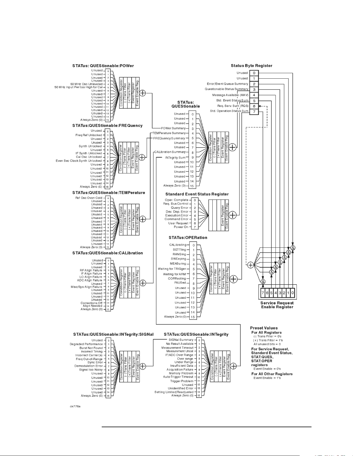
Overall Status Register System
Programming Fundamentals
Using the Instrument Status Registers
Chapter 2 49
Page 50
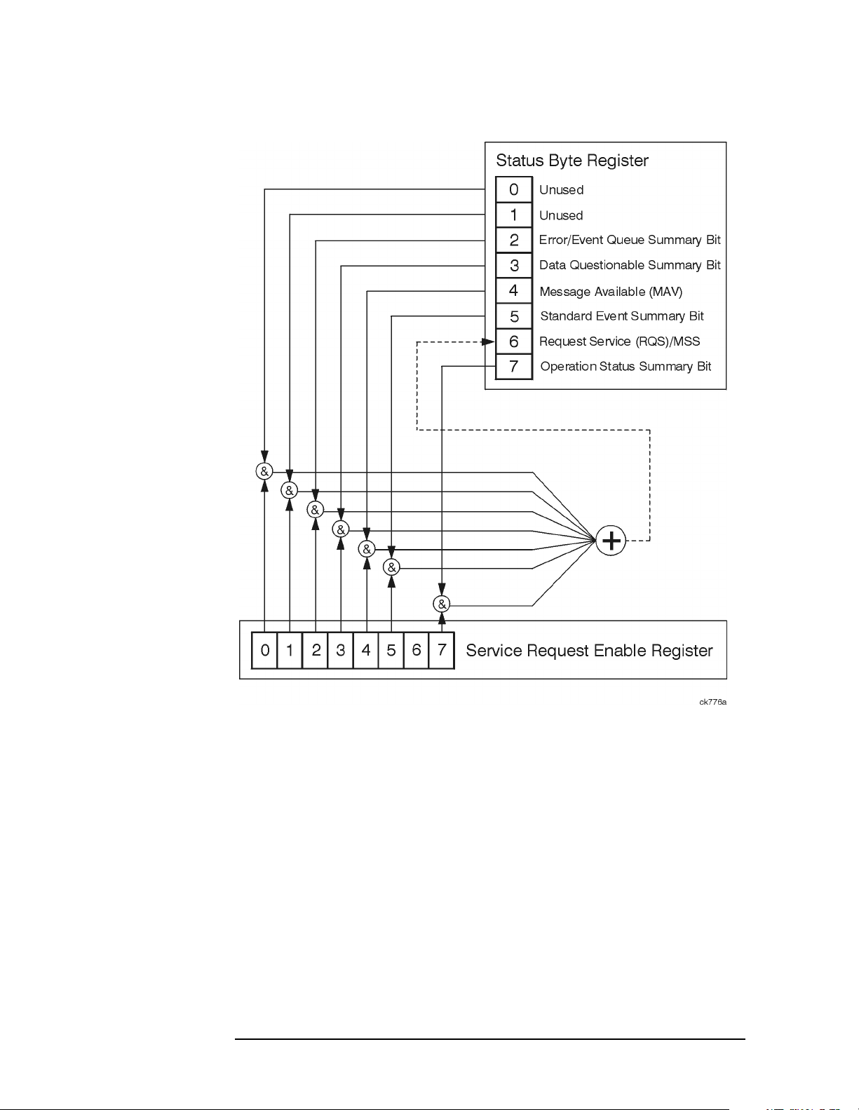
Programming Fundamentals
Using the Instrument Status Registers
Status Byte Register
The RQS bit is read and reset by a serial poll. MSS (the same bit
position) is read, non-destructively by the *STB? command. If you serial
poll bit 6 it is read as RQS, but if you send *STB it reads bit 6 as MSS.
For more information refer to IEEE 488.2 standards, section 11.
50 Chapter2
Page 51
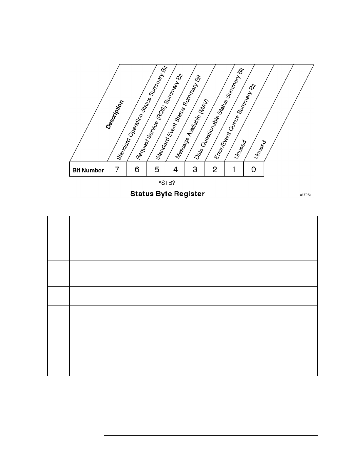
Programming Fundamentals
Using the Instrument Status Registers
Bit Description
0, 1 These bits are always set to 0.
2 A 1 in this bit position indicates that the SCPI error queue is not empty. The SCPI error
queue contains at least one error message.
3 A 1 in this bit position indicates that the data questionable summary bit has been set.
The data questionable event register can then be read to determine the specific condition
that caused this bit to be set.
4 A 1 in this bit position indicates that the instrument has data ready in the output queue.
There are no lower status groups that provide input to this bit.
5 A 1 in this bit position indicates that the standard event summary bit has been set. The
standard event status register can then be read to determine the specific event that
caused this bit to be set.
6 A 1 in this bit position indicates that the instrument has at least one reason to report a
status change. This bit is also called the master summary status bit (MSS).
7 A 1 in this bit position indicates that the standard operation summary bit has been set.
The standard operation event register can then be read to determine the specific
condition that caused this bit to be set.
To query the status byte register, send the command *STB? The
response will be the decimal sum of the bits which are set to 1. For
example, if bit number 7 and bit number 3 are set to 1, the decimal sum
of the 2 bits is 128 plus 8. So the decimal value 136 is returned.
Chapter 2 51
Page 52
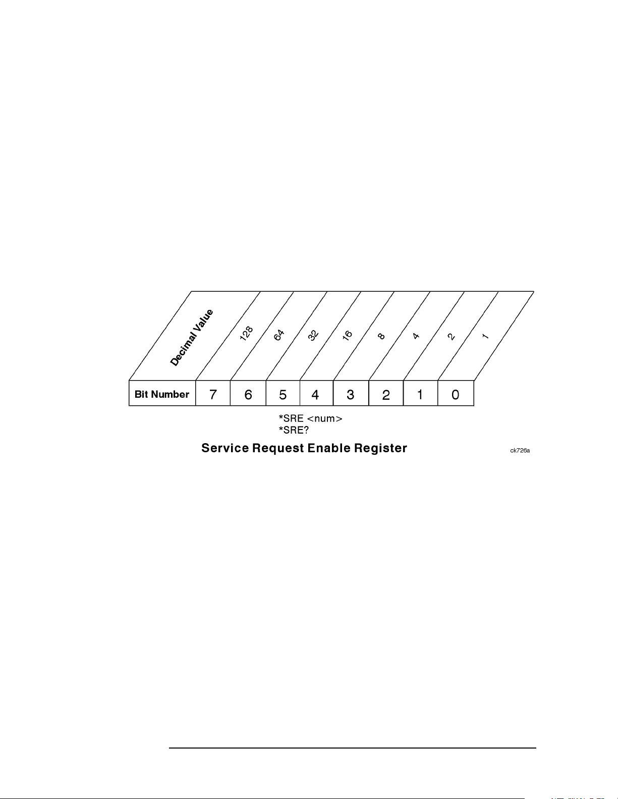
Programming Fundamentals
Using the Instrument Status Registers
In addition to the status byte register, the status byte group also
contains the service request enable register. This register lets you
choose which bits in the status byte register will trigger a service
request.
Send the *SRE <number> command where <number> is the sum of the
decimal values of the bits you want to enable plus the decimal value of
bit 6. For example, assume that you want to enable bit 7 so that
whenever the standard operation status register summary bit is set to 1
it will trigger a service request. Send the command *SRE 192 (128 +
64). You must always add 64 (the numeric value of RQS bit 6) to your
numeric sum when you enable any bits for a service request. The
command *SRE? returns the decimal value of the sum of the bits
previously enabled with the *SRE <number> command.
The service request enable register presets to zeros (0).
52 Chapter2
Page 53

Standard Event Status Register
Programming Fundamentals
Using the Instrument Status Registers
The standard event status register contains the following bits:
Chapter 2 53
Page 54
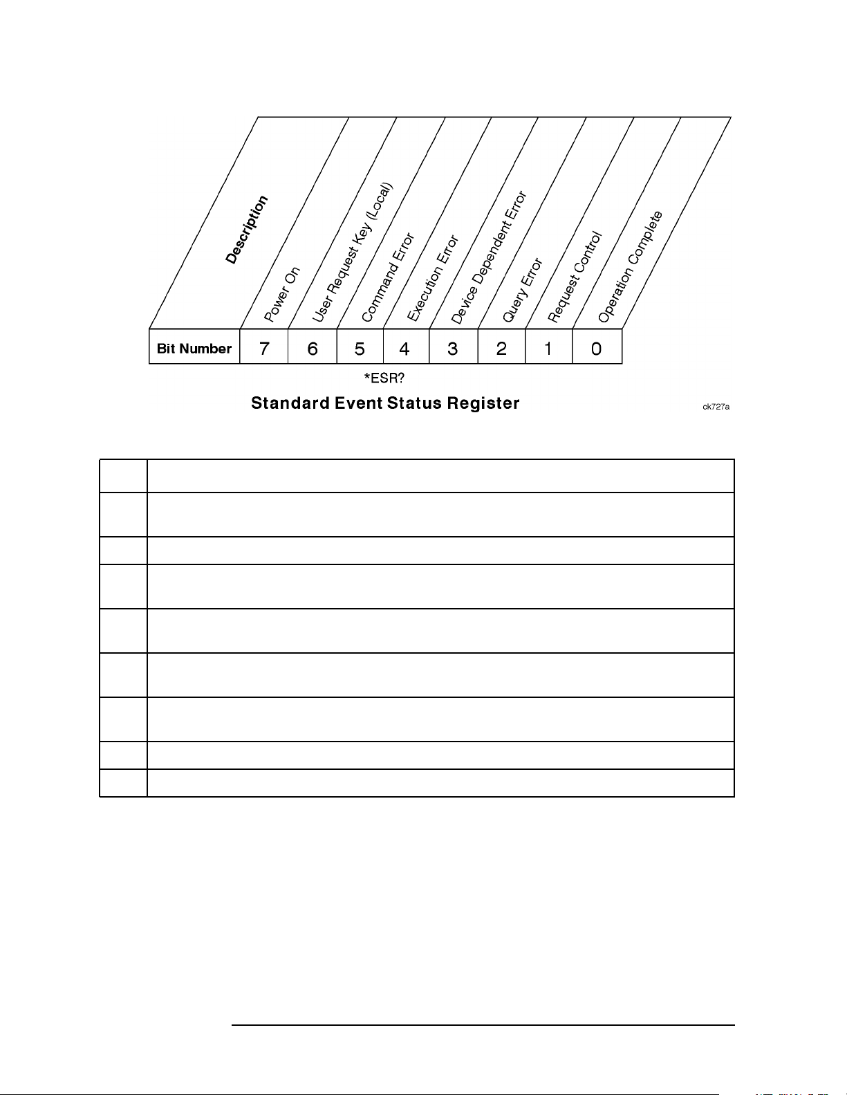
Programming Fundamentals
Using the Instrument Status Registers
Bit Description
0 A 1 in this bit position indicates that all pending operations were completed following
execution of the *OPC command.
1 This bit is always set to 0. (The instrument does not request control.)
2 A 1 in this bit position indicates that a query error has occurred. Query errors have SCPI
error numbers from −499 to −400.
3 A 1 in this bit position indicates that a device dependent error has occurred. Device
dependent errors have SCPI error numbers from −399 to −300 and 1 to 32767.
4 A 1 in this bit position indicates that an execution error has occurred. Execution errors
have SCPI error numbers from −299 to −200.
5 A 1 in this bit position indicates that a command error has occurred. Command errors
have SCPI error numbers from −199 to −100.
6 Currently not used.
7 A 1 in this bit position indicates that the instrument has been turned off and then on.
The standard event status register is used to determine the specific
event that set bit 5 in the status byte register. To query the standard
event status register, send the command *ESR?. The response will be
the decimal sum of the bits which are enabled (set to 1). For example, if
bit number 7 and bit number 3 are enabled, the decimal sum of the 2
bits is 128 plus 8. So the decimal value 136 is returned.
In addition to the standard event status register, the standard event
status group also contains a standard event status enable register. This
register lets you choose which bits in the standard event status register
54 Chapter2
Page 55
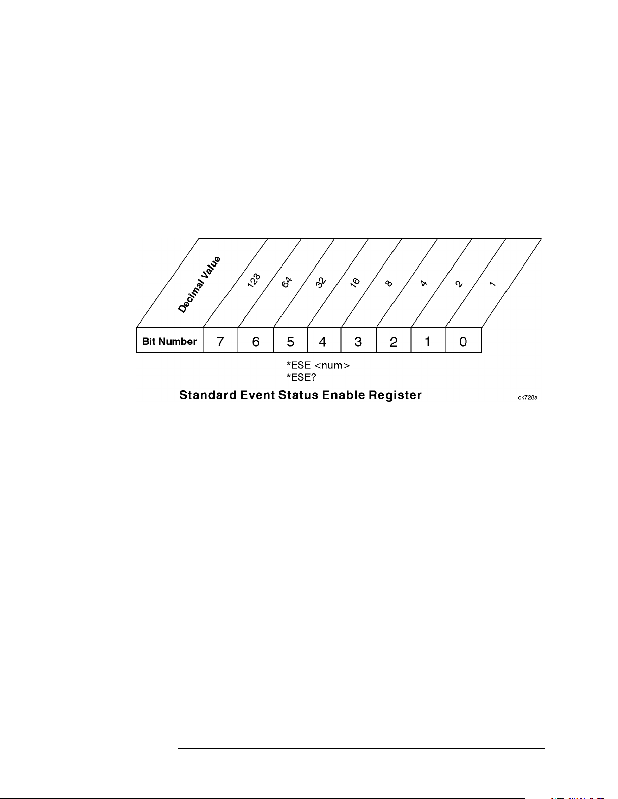
Programming Fundamentals
Using the Instrument Status Registers
will set the summary bit (bit 5 of the status byte register) to 1. Send the
*ESE <number> command where <number> is the sum of the decimal
values of the bits you want to enable. For example, to enable bit 7 and
bit 6 so that whenever either of those bits is set to 1, the standard event
status summary bit of the status byte register will be set to 1, send the
command *ESE 192 (128 + 64). The command *ESE? returns the
decimal value of the sum of the bits previously enabled with the *ESE
<number> command.
The standard event status enable register presets to zeros (0).
Chapter 2 55
Page 56

Programming Fundamentals
Using the Instrument Status Registers
Operation and Questionable Status Registers
The operation and questionable status registers are registers that
monitor the overall instrument condition. They are accessed with the
STATus:OPERation and STATus:QUEStionable commands in the
STATus command subsystem.
Operation Status Register
The operation status register monitors the current instrument
measurement state. It checks to see if the instrument is measuring,
calibrating, sweeping, waiting for a trigger, or what?
Questionable Status Register
The questionable status register monitors the instrument to see if
anything questionable has happened. It is looking for anything that
might cause an error or a bad measurement like a hardware problem,
an out of calibration situation, or a unusual signal. All the bits are
summary bits from lower-level event registers.
56 Chapter2
Page 57

Programming Fundamentals
C Programming Examples using VTL
C Programming Examples using VTL
The programming examples that are provided are written using the C
programming language and the HP/Agilent VTL (VISA transition
library). This section includes some basic information about
programming in the C language. Refer to your C programming
language documentation for more details. (This information is taken
from the manual “VISA Transition Library”, part number
E2090-90026.) The following topics are included:
“Typical Example Program Contents” on page 57
“Linking to VTL Libraries” on page 58
“Compiling and Linking a VTL Program” on page 58
“Example Program” on page 59
“Including the VISA Declarations File” on page 60
“Opening a Session” on page 60
“Device Sessions” on page 61
“Addressing a Session” on page 62
“Closing a Session” on page 64
Typical Example Program Contents
The following is a summary of the VTL function calls used in the
example programs.
visa.h This file is included at the beginning of the file to
provide the function prototypes and constants defined
by VTL.
ViSession The ViSession is a VTL data type. Each object that
will establish a communication channel must be
defined as ViSession.
viOpenDefaultRM You must first open a session with the default
resource manager with the viOpenDefaultRM
function. This function will initialize the default
resource manager and return a pointer to that resource
manager session.
viOpen This function establishes a communication channel
with the device specified. A session identifier that can
be used with other VTL functions is returned. This call
must be made for each device you will be using.
viPrintf
viScanf These are the VTL formatted I/O functions that are
patterned after those used in the C programming
language. The viPrintf call sends the IEEE 488.2
*RST command to the instrument and puts it in a
known state. The viPrintf call is used again to query
Chapter 2 57
Page 58

Programming Fundamentals
C Programming Examples using VTL
for the device identification (*IDN?). The viScanf call
is then used to read the results.
viClose This function must be used to close each session. When
you close a device session, all data structures that had
been allocated for the session will be de-allocated.
When you close the default manager session, all
sessions opened using the default manager session will
be closed.
Linking to VTL Libraries
Your application must link to one of the VTL import libraries:
32-bit Version:
C:\VXIPNP\WIN95\LIB\MSC\VISA32.LIB for Microsoft compilers
C:\VXIPNP\WIN95\LIB\BC\VISA32.LIB for Borland compilers
16-bit Version:
C:\VXIPNP\WIN\LIB\MSC\VISA.LIB for Microsoft compilers
C:\VXIPNP\WIN\LIB\BC\VISA.LIB for Borland compilers
See the following section, “Compiling and Linking a VTL Program” for
information on how to use the VTL run-time libraries.
Compiling and Linking a VTL Program
32-bit Applications
The following is a summary of important compiler-specific
considerations for several C/C++ compiler products when developing
WIN32 applications.
For Microsoft Visual C++ version 2.0 compilers:
• Select Project | Update All Dependencies from the menu.
• Select Project | Settings from the menu. Click on the C/C++
button. Select Code Generation from the Use Run-Time
Libraries list box. VTL requires these definitions for WIN32. Click
on OK to close the dialog boxes.
• Select Project | Settings from the menu. Click on the Link
button and add visa32.lib to the Object / Library Modules
list box. Optionally, you may add the library directly to your project
file. Click on OK to close the dialog boxes.
• You may wish to add the include file and library file search paths.
They are set by doing the following:
1. Select Tools | Options from the menu.
58 Chapter2
Page 59

Programming Fundamentals
C Programming Examples using VTL
2. Click on the Directories button to set the include file path.
3. Select Include Files from the Show Directories For list
box.
4. Click on the Add button and type in the following:
C:\VXIPNP\WIN95\INCLUDE
5. Select Library Files from the Show Directories For list
box.
6. Click on the Add button and type in the following:
C:\VXIPNP\WIN95\LIB\MSC
For Borland C++ version 4.0 compilers:
• You may wish to add the include file and library file search paths.
They are set under the Options | Project menu selection. Double
click on Directories from the Topics list box and add the
following:
C:\VXIPNP\WIN95\INCLUDE
C:\VXIPNP\WIN95\LIB\BC
16-bit Applications
The following is a summary of important compiler-specific
considerations for the Windows compiler.
For Microsoft Visual C++ version 1.5:
• To set the memory model, do the following:
1. Select Options | Project.
2. Click on the Compiler button, then select Memory Model from
the Category list.
3. Click on the Model list arrow to display the model options, and
select Large.
4. Click on OK to close the Compiler dialog box.
• You may wish to add the include file and library file search paths.
They are set under the Options | Directories menu selection:
C:\VXIPNP\WIN\INCLUDE
C:\VXIPNP\WIN\LIB\MSC
Otherwise, the library and include files should be explicitly specified
in the project file.
Example Program
This example program queries a GPIB device for an identification
string and prints the results. Note that you must change the address.
Chapter 2 59
Page 60

Programming Fundamentals
C Programming Examples using VTL
/*idn.c - program filename */
#include "visa.h"
#include <stdio.h>
void main ()
{
/*Open session to GPIB device at address 18 */
ViOpenDefaultRM (&defaultRM);
ViOpen (defaultRM, “GPIB0::18::INSTR”, VI_NULL,
VI_NULL, &vi);
/*Initialize device */
viPrintf (vi, “*RST\n”);
/*Send an *IDN? string to the device */
printf (vi, “*IDN?\n”);
/*Read results */
viScanf (vi, "%t", &buf);
/*Print results */
printf (“Instrument identification string: %s\n”, buf);
/* Close sessions */
viClose (vi);
viClose (defaultRM);
}
Including the VISA Declarations File
For C and C++ programs, you must include the visa.h header file at
the beginning of every file that contains VTL function calls:
#include “visa.h”
This header file contains the VISA function prototypes and the
definitions for all VISA constants and error codes. The visa.h header
file includes the visatype.h header file.
The visatype.h header file defines most of the VISA types. The VISA
types are used throughout VTL to specify data types used in the
functions. For example, the viOpenDefaultRM function requires a
pointer to a parameter of type ViSession. If you find ViSession in the
visatype.h header file, you will find that ViSession is eventually
typed as an unsigned long.
Opening a Session
A session is a channel of communication. Sessions must first be opened
on the default resource manager, and then for each device you will be
using. The following is a summary of sessions that can be opened:
•Aresource manager session is used to initialize the VISA system.
It is a parent session that knows about all the opened sessions. A
60 Chapter2
Page 61

Programming Fundamentals
C Programming Examples using VTL
resource manager session must be opened before any other session
can be opened.
•Adevice session is used to communicate with a device on an
interface. A device session must be opened for each device you will be
using. When you use a device session you can communicate without
worrying about the type of interface to which it si connected. This
insulation makes applications more robust and portable across
interfaces. Typically a device is an instrument, but could be a
computer, a plotter, or a printer.
NOTE All devices that you will be using need to be connected and in working
condition prior to the first VTL function call (viOpenDefaultRM). The
system is configured only on the first viOpenDefaultRM per process.
Therefore, if viOpenDefaultRM is called without devices connected and
then called again when devices are connected, the devices will not be
recognized. You must close ALL resource manager sessions and re-open
with all devices connected and in working condition.
Device Sessions
There are two parts to opening a communications session with a
specific device. First you must open a session to the default resource
manager with the viOpenDefaultRM function. The first call to this
function initializes the default resource manager and returns a session
to that resource manager session. You only need to open the default
manager session once. However, subsequent calls to viOpenDefaultRM
returns a session to a unique session to the same default resource
manager resource.
Next, you open a session with a specific device with the viOpen
function. This function uses the session returned from
viOpenDefaultRM and returns its own session to identify the device
session. The following shows the function syntax:
viOpenDefaultRM (sesn);
viOpen (sesn, rsrcName, accessMode, timeout, vi);
The session returned from viOpenDefaultRM must be used in the sesn
parameter of the viOpen function. The viOpen function then uses that
session and the device address specified in the rsrcName parameter to
open a device session. The vi parameter in viOpen returns a session
identifier that can be used with other VTL functions.
Your program may have several sessions open at the same time by
creating multiple session identifiers by calling the viOpen function
multiple times.
The following summarizes the parameters in the previous function
calls:
Chapter 2 61
Page 62

Programming Fundamentals
C Programming Examples using VTL
sesn This is a session returned from the viOpenDefaultRM
function that identifies the resource manager session.
rsrcName This is a unique symbolic name of the device (device
address).
accessMode This parameter is not used for VTL. Use VI_NULL.
timeout This parameter is not used for VTL. Use VI_NULL.
vi This is a pointer to the session identifier for this
particular device session. This pointer will be used to
identify this device session when using other VTL
functions.
The following is an example of opening sessions with a GPIB
multimeter and a GPIB-VXI scanner:
ViSession defaultRM, dmm, scanner;
.
.
viOpenDefaultRM(&defaultRM);
viOpen (defaultRM, “GPIB0::22::INSTR”, VI_NULL,
VI_NULL, &dmm);
viOpen (defaultRM, “GPIB-VXI0::24::INSTR”, VI_NULL,
VI_NULL, &scanner);
.
.
viClose (scanner);
viClose (dmm);
viClose(defaultRM);
The above function first opens a session with the default resource
manager. The session returned from the resource manager and a device
address is then used to open a session with the GPIB device at address
22. That session will now be identified as dmm when using other VTL
functions. The session returned from the resource manager is then used
again with another device address to open a session with the GPIB-VXI
device at primary address 9 and VXI logical address 24. That session
will now be identified as scanner when using other VTL functions. See
the following section for information on addressing particular devices.
Addressing a Session
As seen in the previous section, the rsrcName parameter in the viOpen
function is used to identify a specific device. This parameter is made up
of the VTL interface name and the device address. The interface name
is determined when you run the VTL Configuration Utility. This name
is usually the interface type followed by a number. The following table
62 Chapter2
Page 63

Programming Fundamentals
C Programming Examples using VTL
illustrates the format of the rsrcName for the different interface types:
Interface Syntax
VXI VXI [board]::VXI logical address[::INSTR]
GPIB-VXI GPIB-VXI [board]::VXI logical address[::INSTR]
GPIB GPIB [board]::primary address[::secondary address][::INSTR]
The following describes the parameters used above:
board This optional parameter is used if you have more than
one interface of the same type. The default value for
board is 0.
VSI logical
address This is the logical address of the VXI instrument.
primary
address This is the primary address of the GPIB device.
secondary
address This optional parameter is the secondary address of the
GPIB device. If no secondary address is specified, none
is assumed.
INSTR This is an optional parameter that indicates that you
are communicating with a resource that is of type
INSTR, meaning instrument.
NOTE If you want to be compatible with future releases of VTL and VISA, you
must include the INSTR parameter in the syntax.
The following are examples of valid symbolic names:
XI0::24::INSTR Device at VXI logical address 24 that is of VISA type
INSTR.
VXI2::128 Device at VXI logical address 128, in the third VXI
system (VXI2).
GPIB-VXI0::24 A VXI device at logical address 24. This VXI device is
connected via a GPIB-VXI command module.
GPIB0::7::0 A GPIB device at primary address 7 and secondary
address 0 on the GPIB interface.
The following is an example of opening a device session with the GPIB
device at primary address23.
ViSession defaultRM, vi;
.
.
Chapter 2 63
Page 64

Programming Fundamentals
C Programming Examples using VTL
viOpenDefaultRM (&defaultRM);
viOpen (defaultRM, “GPIB0::23::INSTR”, VI_NULL,VI_NULL,&vi);
.
.
viClose(vi);
viClose (defaultRM);
Closing a Session
The viClose function must be used to close each session. You can close
the specific device session, which will free all data structures that had
been allocated for the session. If you close the default resource manager
session, all sessions opened using that resource manager will be closed.
Since system resources are also used when searching for resources
(viFindRsrc) or waiting for events (viWaitOnEvent), the viClose
function needs to be called to free up find lists and event contexts.
64 Chapter2
Page 65

Programming Fundamentals
Overview of the GPIB Bus
Overview of the GPIB Bus
GPIB Instrument Nomenclature
An instrument that is part of an GPIB network is categorized as a
listener, talker, or controller, depending on its current function in the
network.
Listener A listener is a device capable of receiving data or
commands from other instruments. Any number of
instruments in the GPIB network can be listeners
simultaneously.
Talker A talker is a device capable of transmitting data or
commands to other instruments. To avoid confusion, an
GPIB system allows only one device at a time to be an
active talker.
Controller A controller is an instrument, typically a computer,
capable of managing the various GPIB activities. Only
one device at a time can be an active controller.
GPIB Command Statements
Command statements form the nucleus of GPIB programming. They
are understood by all instruments in the network. When combined with
the programming language codes, they provide all management and
data communication instructions for the system. Refer to the your
programming language manual and your computers I/O programming
manual for more information.
The seven fundamental command functions are as follows:
• An abort function that stops all listener/talker activity on the
interface bus, and prepares all instruments to receive a new
command from the controller. Typically, this is an initialization
command used to place the bus in a known starting condition
(sometimes called: abort, abortio, reset, halt).
• A remote function that causes an instrument to change from local
control to remote control. In remote control, the front panel keys are
disabled except for the Local key and the line power switch
(sometimes called: remote, resume).
• A local lockout function, that can be used with the remote function,
to disable the front panel Local key. With the Local key disabled,
only the controller (or a hard reset by the line power switch) can
restore local control (sometimes called: local).
• A local function that is the complement to the remote command,
Chapter 2 65
Page 66

Programming Fundamentals
Overview of the GPIB Bus
causing an instrument to return to local control with a fully enabled
front panel (sometimes called: local, resume).
• A clear function that causes all GPIB instruments, or addressed
instruments, to assume a cleared condition. The definition of clear is
unique for each instrument (sometimes called: clear, reset, control,
send).
• An output function that is used to send function commands and data
commands from the controller to the addressed instrument
(sometimes called: output, control, convert, image, iobuffer,
transfer).
• An enter function that is the complement of the output function and
is used to transfer data from the addressed instrument to the
controller (sometimes called: enter, convert, image, iobuffer, on
timeout, set timeout, transfer).
66 Chapter2
Page 67

Programming Fundamentals
Overview of the RS-232 Bus
Overview of the RS-232 Bus
This feature is not implemented.
Serial interface programming techniques are similar to most general
I/O applications. Refer to your programming language documentation
for information on how to initiate the card and verify the status.
Due to the asynchronous nature of serial I/O operations, special care
must be exercised to ensure that data is not lost by sending to another
device before the device is ready to receive. Modem line handshaking
can he used to help solve this problem. These and other topics are
discussed in greater detail in your programming language
documentation.
Settings for the Serial Interface
Please refer to the documentation on your computer and I/O to
configure the serial bus. Some common serial interface configuration
settings are:
Baud Rate to 9600
Bits per character to 8
Parity to Odd and disabled
Stop bits to 1
Handshake and Baud Rate
To determine hardware operating parameters, you need to know the
answer for each of the following questions about the peripheral device:
• Which of the following signal and control lines are actively used
during communication with the peripheral?
— Data Set Ready (DSR)
— Clear to Send (CTS)
• What baud rate is expected by the peripheral?
Character Format Parameters
To define the character format, you must know the requirements of the
peripheral device for the following parameters:
• Character Length: Eight data bits are used for each character,
excluding start, stop, and parity bits.
• Parity Enable: Parity is disabled (absent) for each character.
Chapter 2 67
Page 68

Programming Fundamentals
Overview of the RS-232 Bus
• Stop Bits: One stop bit is included with each character.
Modem Line Handshaking
To use modem line handshaking for data transfer you would consider
the following tasks:
1. Set Data Terminal Ready and Request-to-Send modem lines to
active state.
2. Check Data Set Ready and Clear-to-Send modem lines to be sure
they are active.
3. Send information to the interface and thence to the peripheral.
4. After data transfer is complete, clear Data Terminal Ready and
Request-to-Send signals.
For ENTER operations:
1. Set Data Terminal Ready line to active state. Leave Request-to-Send
inactive.
2. Check Data Set Ready and Data Carrier Detect modem lines to be
sure they are active.
3. Input information from the interface as it is received from the
peripheral.
4. After the input operation is complete, clear the Data TerminalReady
signal.
Data Transfer Errors
The serial interface can generate several types of errors when certain
conditions are encountered while receiving data from the peripheral
device. Errors can be generated by any of the following conditions:
• Parity error. The parity bit on an incoming character does not match
the parity expected by the receiver.This condition is most commonly
caused by line noise.
• Framing error. Start and stop bits do not match the timing
expectations of the receiver. This can occur when line noise causes
the receiver to miss the start bit or obscures the stop bits.
• Overrun error. Incoming data buffer overrun caused a loss of one or
more data characters. This is usually caused when data is received
by the interface, but no ENTER statement has been activated to
input the information.
• Break received. A BREAK was sent to the interface by the
peripheral device. The desktop computer program must be able to
properly interpret the meaning of a break and take appropriate
action.
68 Chapter2
Page 69

Programming Fundamentals
Using the LAN to Control the Analyzer
Using the LAN to Control the Analyzer
• “The Standard UNIX FTP Command:” on page 69
• “Using Telnet to Send Commands” on page 72
• “Using Socket LAN to Send Commands” on page 76
• “Using SICL LAN to Control the Analyzer” on page 77
• “Using HP/Agilent VEE Over Socket LAN” on page 84
• “Using a Java™ Applet Over Socket LAN” on page 85
• “Using a C Program Over Socket LAN” on page 85
• “General LAN Troubleshooting” on page 86
Using ftp for File Transfers
File transfers can be done using the instrument LAN connection. For
example, you can use the ftp functionality to download instrument
screen dumps to an external server.
A sample ftp session might be:
ftp 15.88.163.118 (<instrument IP address>)
At the name prompt enter:
vsa
At the password prompt enter:
service
You are now in the instrument /users directory and can get files from
the analyzer. Type in help at the prompt to see the ftp commands that
are available on your system. Typing quit will end your ftp session.
NOTE Do NOT delete files from this directory. Most of the files are required for
the instrument, and it’s optional personality modes, to operate.
The Standard UNIX FTP Command:
Synopsis ftp [-g] [-i] [-n] [-v] [server-host] [-B
DataSocketBufferSize]
Description The ftp command is used to transfer files using the File
Transfer Protocol. ftp transfers files over a network connection
between a local machine and the remote server-host.
Options and Parameters When ftp is invoked with a server-host
specified, a connection is opened immediately. Otherwise, ftp waits for
user commands.
Chapter 2 69
Page 70

Programming Fundamentals
Using the LAN to Control the Analyzer
The following options are supported:
-g disables expansion of shell metacharacters in file and
-i disables prompts during multiple-file operations
-n disables automatic log-in
-v enables verbose output
-B specifies a new DataSocketBufferSize
server-host the name or address of the remote host.
Table lists the available user commands.
Table 2-1 ftp Commands
Command Description
ascii Sets the file transfer type to ASCII.
binary Sets the file transfer type to binary.
directory names
bye Closes the connection to the host and exits ftp.
cd remote_directory Sets the working directory on the host to remote_directory.
delete remote_file Deletes remote_file or empty remote_directory.
dir
[remote_directory]
get remote_file
[local_file]
help Provides a list of ftp commands.
help command Provides a brief description of command.
image Sets the file transfer type to binary.
lcd [local_directory] Sets the local working directory to local_directory.
ls
[remote_directory]
mget remote_file
[local_file]
Lists the contents of the specified remote_directory. If
remote_directory is unspecified, the contents of the current
remote directory are listed.
Copies remote_file to local_file. If local_file is unspecified,
ftp uses the remote_file name as the local_file name.
Lists the contents of the specified remote_directory. If the
remote_directory is unspecified, the contents of the current
remote directory are listed.
Copy remote_file to the local system. If local_file is
unspecified, ftp uses the remote_file name as the local_file
name.
mput local_file
[remote_file]
put local_file
[remote_file]
70 Chapter2
Copies local_file to remote file. If remote_file is unspecified,
ftp uses the local_file name as the remote_file name.
Copies local_file to remote file. If remote_file is unspecified,
ftp uses the local_file name as the remote_file name.
Page 71

Table 2-1 ftp Commands
Command Description
quit Closes the connection to the host and exits ftp.
Programming Fundamentals
Using the LAN to Control the Analyzer
Chapter 2 71
Page 72

Programming Fundamentals
Using the LAN to Control the Analyzer
Using Telnet to Send Commands
Using telnet to send commands to your analyzer works in a similar way
to communicating over GPIB. You establish a connection with the
analyzer, and then send or receive information using SCPI commands.
NOTE If you need to control the GPIB using “device clear” or SRQ’s, you can
use SICL LAN. SICL LAN provides control of your analyzer via IEEE
488.2 GPIB over the LAN. See “Using SICL LAN to Control the
Analyzer” on page 77. in this chapter.
On unix:
The syntax of the telnet command is:
telnet <vsa hostname> 5023
or
telnet <IP address>
The initial telnet connection message will be displayed and then a
SCPI> prompt. At the SCPI prompt, simply enter the desired SCPI
commands.
On a PC:
You would type at the dos prompt
telnet
The telnet gui has the host/port setting menu.
Unix Telnet Example:
To connect to the instrument with host name my4406 and port number
5023, enter the following command:
telnet my4406 5023
NOTE You must have changed your instrument host name from the default
(for example, change E566DD69 to my4406) in order to specify your
instrument by name. Press
System, Config I/O, Host Name.
Alternately, you can enter the IP address directly in the telnet
command, in place of the analyzer name:
telnet 15.4.45.255 5023
The computer responds with the following messages:
Trying...
Connected to 15.4.45.255.
Escape character is '^]'.
When you connect to the instrument, it will display a welcome message
72 Chapter2
Page 73

Programming Fundamentals
Using the LAN to Control the Analyzer
and a command prompt.
The instrument is now ready to accept your SCPI commands. As you
type SCPI commands, query results appear on the next line. When you
are done, break the telnet connection using the escape character (in this
case Ctrl ]), and type quit.
The analyzer responds with the a welcome message and the SCPI
prompt. You can immediately enter programming (SCPI) commands.
Typical commands might be:
CONF:SPECTRUM
CALC:SPECTRUM:MARK:TRACE SPECTRUM
CALC:SPECTRUM:MARK:MAX
CALC:SPECTRUM:MARK:MAX?
The small program above sets the analyzer to measure a signal in the
frequency domain, places a marker on the maximum point, and then
queries the analyzer for the amplitude of the marker.
You need to press Enter after typing in each command. After pressing
Enter on the last line in the example above, the analyzer returns the
amplitude level of the marker to your computer and displays it on the
next line. For example, after typing CALC:SPECTRUM:MARK:MAX? and
pressing Enter, the computer would display:
+1.71000000000E+002
When you are done, close the telnet connection. Enter the escape
character to get the telnet prompt. The escape character (Ctrl and "]" in
this example) does not print.
At the telnet prompt, type quit or close.
The telnet connection closes and you see your regular prompt.
Connection closed.
Figure 2-2 shows a terminal screen using the example commands
above.
Chapter 2 73
Page 74

Programming Fundamentals
Using the LAN to Control the Analyzer
Figure 2-2 Example telnet Session
NOTE If your telnet connection is in a mode called "line-by-line," there is no
local echo. This means you will not be able to see the characters you are
typing on your computer's display until after you press the Enter key.
To remedy this, you need to change your telnet connection to
"character-by-character" mode. This can be accomplished in most
systems by escaping out of telnet to the telnet> prompt and then
typing mode char. If this does not work, consult your telnet program's
documentation for how to change to "character-by-character" mode.
The Standard UNIX TELNET Command:
Synopsis telnet [host [port]]
Description The telnet command is used to communicate with
another host using the TELNET protocol. When telnet is invoked with
host or port arguments, a connection is opened to host, and input is
sent from the user to host.
Options and Parameters telnet operates in line-by-line mode or in
character-at-a-time mode. In line-by-line mode, typed text is first
echoed on the screen. When the line is completed by pressing the
Enter
key, the text line is then sent to host. In character-at-a-time mode, text
is echoed to the screen and sent to host as it is typed.
In some cases, if your telnet connection is in “line-by-line” mode, there
74 Chapter2
Page 75

Programming Fundamentals
Using the LAN to Control the Analyzer
is no local echo. This means you will not be able to see the characters
you are typing on your computer's display until after you press the
Enter
key.
To remedy this, you need to change your telnet connection to
“character-by-character” mode. This can be accomplished in most
systems by escaping out of telnet to the telnet> prompt and then
typing mode char. Consult your telnet program's documentation for
how to change to “character-by-character” mode.
Chapter 2 75
Page 76

Programming Fundamentals
Using the LAN to Control the Analyzer
Using Socket LAN to Send Commands
Your analyzer implements a sockets Applications Programming
Interface (API) compatible with Berkeley sockets, Winsock, and other
standard sockets APIs. Youcan write programs using sockets to control
your analyzer by sending SCPI commands to a socket connection you
create in your program. Refer to Using a Java™ Applet Over Socket
LAN in this chapter for example programs using sockets to control the
analyzer.
Setting Up Your Analyzer for Socket Programming
Before you can use socket programming, you must identify your
analyzer’s socket port number. The default is 5025:
1. Press
System, Config I/O, SCPI LAN, Socket Port.
2. Notice that the port number you will use for your socket connection
to the analyzer is 5025.
76 Chapter2
Page 77

Programming Fundamentals
Using the LAN to Control the Analyzer
Using SICL LAN to Control the Analyzer
SICL LAN is a LAN protocol using the Standard Instrument Control
Library (SICL). It provides control of your analyzer over the LAN, using
a variety of computing platforms, I/O interfaces, and operating systems.
With SICL LAN, you control your remote analyzer over the LAN with
the same methods you use for a local analyzer connected directly to the
controller with the GPIB. More information about SICL LAN can be
found in the HP Standard Instrument Control Library user’s guide for
HP-UX, part number E2091-90004.
Your analyzer implements a SICL LAN server. To control the analyzer,
you need a SICL LAN client application running on a computer or
workstation that is connected to the analyzer over a LAN. Typical
applications implementing a SICL LAN client include
• HP/Agilent VEE
• HP/Agilent BASIC
• National Instrument’s LabView with HP/Agilent VISA/SICL client
drivers
NOTE The SICL LAN protocol is Agilent’s implementation of the VXI-11
Instrument Protocol, defined by the VXIbus Consortium working group.
At the time of the publication of this manual, National Instruments’
VISA does not support the VXI-11 Instrument Protocol. However,
future revisions of National Instruments VISA will support the VX-11
protocol. Contact National Instruments for their release date.
SICL LAN can be used with Windows 95, Windows 98, Windows NT,
and HP-UX.
Chapter 2 77
Page 78

Programming Fundamentals
Using the LAN to Control the Analyzer
Collecting SICL LAN Set-up Information
Before you set up your analyzer as a SICL LAN server,you will need to
collect some information about your VISA/SICL LAN client application.
The “value” of the following parameters can be found from the front
panel
System keys. They can then be used to set up your VISA/SICL
LAN client application:
Emulated GPIB
Name The GPIB name is the name given to a device used to
communicate with the analyzer. Your analyzer is
shipped with gpib7 as its GPIB name. The GPIB name
is the same as the remote SICL address.
Emulated GPIB
Logical Unit The logical unit number is a unique integer assigned to
the device to be controlled using SICL LAN. Your
analyzer is shipped with the logical unit number set to
8.
Emulated GPIB
Address The emulated GPIB address (bus address) is assigned
to the device to be controlled using SICL LAN. The
emulated GPIB address is automatically set to be the
same as the current GPIB address. The instrument is
shipped with the emulated GPIB address set to 18.
The SICL LAN server uses the GPIB name, GPIB logical unit number,
and GPIB address configuration on the SICL LAN client to
communicate with the client. You must match these parameters exactly
(including case) when you set up the SICL LAN client and server.
Configuring Your Analyzer as a SICL LAN Server
After you have collected the required information from the SICL LAN
client, perform the following steps to set up your analyzer as a SICL
LAN server:
1. Identify the GPIB name.
Press
System, Config I/O, SICL Server, Emulated GPIB Name, and notice
that it is gpib7.
2. Notice that the Emulated GPIB Logical Unit is set to 8.
3. Notice that the
Emulated GPIB Address is set the same as the GPIB
address.
Configuring Your PC as a SICL LAN Client
The descriptions here are based on Agilent’s VISA revision G.02.02,
model number 2094G. A copy of Agilent’s VISA can be found on
Agilent’s website:
http://www.tm.agilent.com/tmo/software/English/HP_IO_Libraries.html
78 Chapter2
Page 79

Programming Fundamentals
Using the LAN to Control the Analyzer
These descriptions assume a LAN connection between your computer
and network analyzer. They are not written for the GPIB to LAN
gateway.
1. Install VISA revision G.02.02 or higher.
2. Run I/O configuration.
3. Select LAN Client from the available interface types.
4. Press Configure.
5. Enter an interface name, such as lan1.
6. Enter a logical unit number, such as 7.
7. Select Okay.
8. Select VISA LAN Client from the available interface types.
9. Press Configure.
10.Enter a VISA interface name, such as GPIB1.
11.Enter the hostname or IP address of your analyzer in the hostname
field, such as my4406a.companyname.com
12.Enter a Remote SICL address, such as GPIB1.
13.Set the LAN interface to match the defined LAN client (lan1 in this
example).
14.Select OK.
15.Close I/O Configuration by selecting OK.
Controlling Your Analyzer with SICL LAN and HP/Agilent VEE
Before you can use SICL LAN with VEE, you need to set up VISA/SICL
LAN I/O drivers for use with your VEE application. Consult your VEE
documentation for information how to do this.
NOTE If you are using HP/Agilent VEE and SICL LAN, the logical unit
number is limited to the range of 0-8.
The logical unit number is the same as the interface select code (ISC).
VEE reserves ISC values 9-18, and does not allow you to use them for
SICL/LAN communications with your analyzer. VEE also does not
allow any ISC values higher than 18.
After you have the VISA/SICL LAN I/O drivers installed, perform the
steps below to set up VEE to control your analyzer:
1. On your computer or workstation, select I/O|Instrument Manager.
Chapter 2 79
Page 80

Programming Fundamentals
Using the LAN to Control the Analyzer
Figure 2-3 I/O|Instrument Manager Menu
2. Add a new GPIB device with an address of 7XX, where XX is the
GPIB device address from your analyzer.
Figure 2-4 Adding Your Analyzer as an VEE Device
80 Chapter2
Page 81
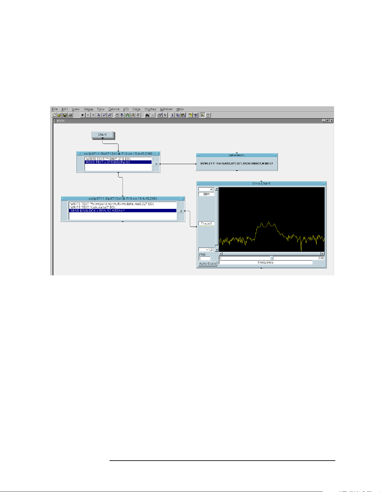
Programming Fundamentals
Using the LAN to Control the Analyzer
To send SCPI commands to the analyzer, select I/O|Instrument
Manager, and the GPIB device just added. Select Direct I/O. You can
now type SCPI commands in the command window, and they are sent
over the LAN to your analyzer.
Figure 2-5 Sending SCPI Commands Directly to your Analyzer
See the VEE example program for more details.
Chapter 2 81
Page 82

Programming Fundamentals
Using the LAN to Control the Analyzer
Controlling Your Analyzer with SICL LAN and HP/Agilent
BASIC for Windows
Before you can use HP/Agilent BASIC for Windows with SICL LAN,
you need to set up VISA/SICL LAN I/O drivers for use with your BASIC
applications. Consult your BASIC documentation for information how
to do this.
To set up SICL LAN for BASIC, add the following statement to your
AUTOST program (all on a single line):
LOAD BIN “GPIBS;DEV lan[analyzer IP address]:GPIB name TIME 30 ISC 7”
Replace analyzer IP address with the IP address of your analyzer,
GPIP name with the GPIB name given to your analyzer, and 7 with the
logical unit number.
For example, the following LOAD statement should be added to your
AUTOST program for the parameters listed below:
analyzer IP address 12.22.344.225
analyzer GPIB name inst0
logical unit number 7
timeout value (seconds) 30
LOAD statement (all on a single line)
LOAD BIN “GPIBS;DEV lan[12.22.344.225]:inst0 TIME 30 ISC 7”
82 Chapter2
Page 83

Programming Fundamentals
Using the LAN to Control the Analyzer
Consult your BASIC documentation to learn how to load the SICL
driver for BASIC.
After the SICL driver is loaded, you control your analyzer using
commands such as the following:
OUTPUT 718; “*IDN?”
ENTER 718; S$
where 18 is the device address for the analyzer.
See the BASIC example program in this chapter for more information.
Controlling Your Analyzer with SICL LAN and BASIC for UNIX
(Rocky Mountain BASIC)
Before you can use Rocky Mountain Basic (HPRMB) with SICL LAN,
you will need to set up the SICL LAN I/O drivers for HPRMB. Consult
your system administrator for details.
Create a .rmbrc file in your root directory of your UNIX workstation
with the following entries:
SELECTIVE_OPEN=ON
Interface 8= “lan[analyzer IP address]:GPIB name”;NORMAL
Replace analyzer IP address with the IP address of your analyzer,
and GPIB name with the GPIB name given to your analyzer. Also
replace the “8” of Interface 8 with the logical unit number. Consult
your HPRMB documentation for the exact syntax.
After your SICL driver is configured correctly on your UNIX
workstation, you control your analyzer using commands such as the
following:
OUTPUT 818; “*IDN?”
ENTER 818; S$
where 18 is the device address for the analyzer.
Chapter 2 83
Page 84
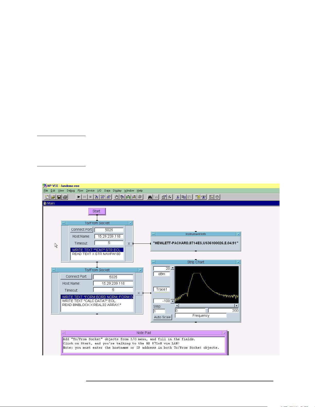
Programming Fundamentals
Using the LAN to Control the Analyzer
Using HP/Agilent VEE Over Socket LAN
To control your analyzer via socket LAN using VEE, click on the VEE
menu titled "I/O." Then select "To/From Socket" and position the I/O
object box on the screen. Fill in the following fields:
Connect Port: 5025
Host Name: <hostname>
Timeout: 15
Forfaster troubleshooting, you may want to set the timeout to a smaller
number. If the hostname you enter doesn't work, try using the IP
address of your analyzer (example: 15.4.43.5). Using the IP address
rather than the hostname may also be faster. See Figure 2-6 for an
example of an VEE screen.
NOTE If you need to control the GPIB using “device clear” or SRQ’s, you can
use SICL LAN. SICL LAN provides control of your analyzer via IEEE
488.2 GPIB. See See “Using SICL LAN to Control the Analyzer” on
page 77. in this chapter.
Figure 2-6 Sample VEE Screen
84 Chapter2
Page 85

Programming Fundamentals
Using the LAN to Control the Analyzer
Using a Java™ Applet Over Socket LAN
The example program “Using Java Programming Over Socket LAN” on
page 126 demonstrates simple socket programming with Java. It is
written in Java programming language, and will compile with Java
compilers versions 1.0 and above.
This program is on your documentation CD ROM that shipped with the
product.
Using a C Program Over Socket LAN
The example programs “Using C Programming Over Socket LAN” on
page 109 and “Using C Programming Over Socket LAN (Windows NT)”
on page 123demonstrate simple socket programming. They are written
in C, and compile in the HP-UX UNIX environment, or the WIN32
environment.
In UNIX, LAN communication via sockets is very similar to reading or
writing a file. The only difference is the openSocket() routine, which
uses a few network library routines to create the TCP/IP network
connection. Once this connection is created, the standard fread() and
fwrite() routines are used for network communication.
In Windows, the routines send() and recv() must be used, since
fread() and fwrite() may not work on sockets.
Chapter 2 85
Page 86

Programming Fundamentals
Using the LAN to Control the Analyzer
General LAN Troubleshooting
• “Troubleshooting the Initial Connection” on page 86
• “Common Problems After You’ve Made the Connection” on page 87
• “Pinging the Analyzer from Your Computer or Workstation” on page
89
• “EIA/TIA 568B Wiring Information” on page 91
Troubleshooting the Initial Connection
Getting the analyzer to work with your network often requires detailed
knowledge of your local network software.This section attempts to help
you with some common problems. Contact your network administrator
for additional assistance.
The analyzer LAN interface does not need or include any proprietary
driver software. It was designed to operate with common network
utilities and drivers.
Either a hardware problem or a software problem can prevent the
analyzer's remote file server from communicating over the LAN. The
following common problems may be encountered:
Communications Not Established If you have just installed and
configured the LAN interface and you have never been able to access
the analyzer via ftp or telnet, go directly to “Pinging the Analyzer
from Your Computer or Workstation” on page 89.
If you have previously been able to access the analyzer via ftp or
telnet and now cannot do so, check the following:
❏ Has any hardware been added or moved on your network? This
includes adding or removing any workstations or peripherals, or
changing any cabling.
❏ Have software applications been added to the network?
❏ Has the functionality been turned off from the front panel? Press
System, Config I/O, SCPI LAN.
❏ Have any configuration files been modified? Pressing
Restore Sys Defaults restores the original factory defaults and you
System,
will have to re-set the instrument IP address and hostname.
❏ Is the upper- and lower-case character usage in your hostname
consistent?
❏ Have any of the following files been deleted or overwritten?
UNIX:
— /etc/hosts
— /etc/inetd.conf
86 Chapter2
Page 87

Programming Fundamentals
Using the LAN to Control the Analyzer
— /etc/services
PCs:
— dependent network files
If you know or suspect that something has changed on your network,
consult with your network administrator.
Timeout Errors Timeout errors such as "Device Timeout," "File
Timeout," and "Operation Timeout," are symptoms of one or both of
the following problems:
— The currently configured timeout limits are too short compared to
the time it takes the LAN to complete some operations. This
problem may occur during periods of increased LAN traffic.
— The LAN connection has failed, or fails occasionally.
To increase your timeout period, refer to your computer
documentation for instructions. Contact your LAN administrator if
problems continue.
Packets Routinely Lost If packets are routinely lost, proceed to the
troubleshooting section in this chapter relating to your network.
Problems Transferring or Copying Files If you have problems
copying files out of or into the analyzer, you might be experiencing
timeout problems. See the previous section on "Timeout Errors."
Common Problems After You’ve Made the Connection
This section describes common problems you may encounter when
using the analyzer on a LAN. It assumes you have been able to connect
to the analyzer in the past. If this is not so, refer to the previous
sections first.
NOTE Pressing Preset does not affect LAN settings, but pressing System,
Restore Sys Defaults will reset to the original factory defaults. You will
then have to re-set the instrument IP address and other LAN settings
in System, Config I/O.
You cannot connect to the analyzer
• If you suspect a bad LAN connection between your computer and
analyzer, you can verify the network connection by using the ping
command described earlier in this chapter or another similar echo
request utility.
• If a bad connection is revealed, try the following solutions:
— Make sure the analyzer is turned on.
— Check the physical connection to the LAN.
Chapter 2 87
Page 88

Programming Fundamentals
Using the LAN to Control the Analyzer
— Make sure the internet (IP) Address of the analyzer is set up
correctly in the LAN port setup menu. (Press
Address.)
System, Config I/O, IP
— If the analyzer and the computer are on different networks or
subnets, make sure the gateway address and subnet mask values
are set correctly. See "Troubleshooting Subnet Problems" earlier
in this chapter.
You cannot access the file system via ftp
• If you get a "connection refused" message, try the following
solutions:
— If the power to the analyzer was just turned on, make sure that
you wait about 25 seconds before attempting the connection.
• If you get a "connection timed out" message
— Verify the LAN connection between your computer and the
analyzer. Refer to "If you cannot connect to the analyzer" earlier
in this section.
You cannot telnet to the command parser port
• If you get a "connection refused" message
— Check the telnet port number from the front panel keys.
• If you get a "connection timed out" or "no response from host"
message
— Verify the LAN connection between your computer and the
analyzer. Refer to "If you cannot connect to the analyzer" earlier
in this section.
• If you get a "connection refused" or "no response from host" message
— If the analyzer was just turned on, make sure that you wait about
25 seconds before attempting the connection.
You get an "operation timed-out" message
• Check the LAN connection between the computer and the analyzer.
Refer to "If you cannot connect to the analyzer" in this section.
• Increase the file time-out value on your PC or workstation.
You cannot access internal web pages or import graphic images
when using a point-to-point connection
• Disable the use of proxy servers. You may have to specify this in a
number of locations, depending on the operating system and
software you are using.
• Disable the use of cached copies of web pages to ensure that you
88 Chapter2
Page 89

Programming Fundamentals
Using the LAN to Control the Analyzer
always get a new copy of the analyzer’s screen image.
If all else fails
• Contact your network administrator.
• If you still cannot solve the problem, contact an Agilent Service
Center for repair information.
Pinging the Analyzer from Your Computer or Workstation
Verify the communications link between the computer and the analyzer
remote file server using the ping utility.
From a UNIX workstation, type:
ping hostname 64 10
where 64 is the packet size, and 10 is the number of packets
transmitted.
From a DOS or Windows environment, type:
ping hostname 10
where 10 is the number of echo requests.
Normal Response for UNIX
A normal response to the ping will be a total of 9, 10, or possibly 11
packets received with a minimal average round-trip time. The
minimal average will be different from network to network. LAN
traffic will cause the round-trip time to vary widely.
Because the number of packets received depends on your network
traffic and integrity, the normal number might be different for your
network.
Normal Response for DOS or Windows
A normal response to the ping will be a total of 9, 10, or possibly 11
packets received if 10 echo requests were specified.
Because the number of packets received depends on your network
traffic and integrity, the normal number might be different for your
network.
Error Messages
If error messages appear, then check the command syntax before
continuing with the troubleshooting. If the syntax is correct, then
resolve the error messages using your network documentation, or by
consulting your network administrator.
If an unknown host error message appears, then check that the host
name and IP address for your analyzer are correctly entered from
the front panel. Press
Chapter 2 89
System, Config I/O.
Page 90

Programming Fundamentals
Using the LAN to Control the Analyzer
No Response No packets received indicates no response from a ping.
If there is no response, try typing in the IP address with the ping
command, instead of using the hostname. Check that the typed
address matches the IP address assigned in the
System, Config I/O
menu, then check the other addresses in the menu.
Check that the hostname and IP address are correctly entered in the
node names database.
If you are using a UNIX environment, ping each node along the
route between your workstation and the analyzer, starting with the
your workstation. Ping each gateway, then attempt a ping of the
remote file server.
If the analyzer still does not respond to ping, then you should
suspect a hardware problem with the analyzer. To check the
analyzer performance, refer to "Verify the Analyzer Performance" in
this chapter.
Intermittent Response If you received 1 to 8 packets back, there is
probably a problem with the network. Because the number of
packets received depends on your network traffic and integrity, the
number might be different for your network.
Use a LAN analyzer or LAN management software to monitor
activity and determine where bottlenecks or other problems are
occurring. The analyzer will still function, but communications over
the LAN will be slower.
On a single-client/single-server network, the most likely cause of
intermittent response to an echo request is a hardware problem with
the LAN module installed in the PC, the cable, or the analyzer. To
check the analyzer, refer to "Verify the Analyzer Performance" later
in this chapter.
The Standard UNIX PING Command
host [packetsize] [count]
Description The ping command sends an echo request packet to the host
once per second. Each echo response packet that is returned is listed on the
screen, along with the round-trip time of the echo request and echo response.
Options and Parameters -r Bypasses the routing tables, and sends the
request directly to the host.
-v Reports all packets that are received, including the response
packets.
-o Requests information about the network paths taken by the
requests and responses.
Synopsis ping [-r] [-v] [-o]
host The host name or IP address.
packetsize The size of each packet (8 bytes - 4096 bytes).
90 Chapter2
Page 91

Programming Fundamentals
Using the LAN to Control the Analyzer
count The number of packets to send before ending ping (1-(231-1)).
If count is not specified, ping sends packets until
interrupted.
EIA/TIA 568B Wiring Information
Table 2-2 Straight-Through Cable (Unshielded-twisted-pair (UTP) cable
with RJ-45 connectors)
Standard, Straight-Through Wiring (each end)
Signal Name RJ-45 Pin # Wire Color Pair #
RX+ 1 white/orange 2
RX- 2 orange
TX+ 3 white/green 3
TX- 6 green
Not
Used
4 blue 1
5 white/blue
7 white/brown 4
8 brown
Table 2-3 Cross-Over Cable (Unshielded-twisted-pair (UTP) cable with
RJ-45 connectors)
Cross-Over Wiring
Connector A Connector B
Signal Name RJ-45 Pin # RJ-45 Pin # Signal Name
RX+ 1 3 TX+
RX- 2 6 TXTX+ 3 1 RX+
TX- 6 2 RXNot
Used
a
4 4 Not
Used
55
77
88
a. Either end of this cable can be used at the analyzer or
LAN device. The connector names are a convention useful during cable construction only.
Chapter 2 91
Page 92

Programming Fundamentals
Using the LAN to Control the Analyzer
This cable can be used to cascade hubs or to make point-to-point
connections without a LAN hub.
NOTE A convenient wayto make a cross-over adapter is to use two RJ-45 jacks
wired according to Table , above. Standard straight-through patch
cables can then be used from the analyzer to the adapter, and from the
adapter to other LAN devices. If you use a special-purpose adapter, you
will avoid having a cross-over cable mistaken for a standard,
straight-through patch cable.
NOTE Some commercially-available cross-over cables do not implement the
cross-over wiring required for your analyzer. Please refer to Table ,
above, and verify all connections before using cables not made by
Agilent Technologies.
Figure 2-7 Cross-Over Patch Cable Wiring (cross-over end)
92 Chapter2
Page 93

3 Programming Examples
93
Page 94

Programming Examples
Types of Examples
Types of Examples
This section includes examples of how to program the instrument using
the instrument SCPI programming commands. The most of the
examples are written for a PC, using GPIB. They are written in the C
programming language and use the HP/Agilent VISA transition library.
The VISA transition library must be installed and the GPIB card
configured.
These examples are available on the Agilent Technologies E4406A
documentation CD-ROM. They are also available at the URL
http://www.agilent.com/find/vsa
The section “C Programming Examples using VTL” on page 57,
includes some basic information about using the C programming
language. That information can be used with the examples in this
chapter to create your own measurement routines.
Examples are also available showing you how to program the
instrument using the VXIplug&play instrument driver that is provided.
The examples are included in the on-line documentation in the driver
itself. The driver allows you to use several different programming
languages including: VEE, LabView, C, C++, BASIC. The software
driver can be found at the URL http://www.agilent.com/find/vsa.
The programming examples include:
• “Using Markers” on page 95
• “Saving Binary Trace Data in an ASCII File” on page 98
• “Saving ASCII Trace Data in an ASCII File” on page 101
• “Saving and Recalling Instrument State Data” on page 104
• “Performing Alignments and Getting Pass/Fail Results” on page 107
• “Using C Programming Over Socket LAN” on page 109
• “Using C Programming Over Socket LAN (Windows NT)” on page
123
• “Using Java Programming Over Socket LAN” on page 126
94 Chapter3
Page 95

Programming Examples
Using Markers
Using Markers
This C programming example (HPE4406Markers.c):
• uses the VISA library for input/output, opens a session to a GP-IB
device at address 18 and presets the instrument.
• sets the input to the internal 50 MHz reference source and tunes the
instrument to the signal.
• turns off the active trace and put the instrument in single
measurement mode.
• initiates a spectrum measurement and waits for the operation to
complete.
• puts marker 1 on the peak signal of the average trace and measures
the amplitude.
• puts a noise type marker (marker 2) on the average trace and
measures the amplitude.
• calculates the difference between the peak and the noise floor.
• puts the instrument back in continuous measurement mode and
prints the results.
Chapter 3 95
Page 96

Programming Examples
Using Markers
Example:
#include <stdio.h>
#include <stdlib.h>
#include <stdmath.h>
#include "visa.h"
void main ()
{
/*program variables*/
ViSession defaultRM, viVSA;
ViStatus viStatus = 0;
double dPeakPower = 0;
double dNoiseMarker = 0;
double dResult= 0;
long lComplete = 0;
/*open session to GPIB device at address 18 */
viStatus=viOpenDefaultRM (&defaultRM);
viStatus=viOpen (defaultRM, "GPIB0::18::INSTR",
VI_NULL,VI_NULL, &viVSA);
/*check opening session sucess*/
if(viStatus)
{
printf("Could not open a session to GPIB device at
address 18!\n");
exit(0);
}
/*reset the instrument */
viPrintf(viVSA, "*RST\n");
/*set the input port to the internal 50Mhz reference
source*/
viPrintf(viVSA, "SENS:FEED AREF\n");
/*tune the instrument to 50MHZ*/
viPrintf(viVSA, "SENS:FREQ:CENT 50E6\n");
/*put the instrument in single measurement mode*/
viPrintf(viVSA, "INIT:CONT 0\n");
/*zoom the spectrum display*/
viPrintf(viVSA, "DISP:FORM:ZOOM1\n");
/*trigger a spectrum measurement*/
viPrintf(viVSA, "INIT:IMM;*OPC?\n");
/*poll the operation complete query*/
while (!lComplete)
viScanf (viVSA,"%d",&lComplete);
/*assign marker 1 to the average trace of the spectrum*/
viPrintf(viVSA, "CALC:SPEC:MARK1:TRAC ASP\n");
/*put the marker 1 on the signal peak*/
96 Chapter3
Page 97

Programming Examples
Using Markers
viPrintf(viVSA, "CALC:SPEC:MARK1:MAX\n");
/*query the 50 MHz signal amplitude*/
viPrintf(viVSA, "CALC:SPEC:MARK1:Y?\n");
/*get the 50 MHz signal amplitude*/
viScanf (viVSA,"%lf",&dPeakPower);
/*assign marker 2 to the average trace of the spectrum*/
viPrintf(viVSA, "CALC:SPEC:MARK2:TRAC ASP\n");
/*assign the marker function NOISE to marker 2 */
viPrintf(viVSA, "CALC:SPEC:MARK2:FUNC NOISE\n");
/*position marker 2 on the noise floor*/
viPrintf(viVSA, "CALC:SPEC:MARK2:X 50.2E6\n");
/*query NOISE marker*/
viPrintf(viVSA, "CALC:SPEC:MARK2:FUNC:RES?\n");
/*get the the NOISE marker reading*/
viPrintf (viVSA,"%lf",&dNoiseMarker);
/*put the instrument back to continuous mode*/
viScanf (viVSA,"INIT:CONT 1\n");
/*calculate the difference between the marker peak and
the NOISE marker*/
dResult = fabs(dNoiseMarker - dPeakPower);
/*print result to the standard output*/
printf("The Peak Marker measured = %.2lf
dBm\n",dPeakPower);
printf("The Noise Marker at 50.2 MHz measured = %.2lf
dBm/Hz\n",dNoiseMarker);
printf("The difference between the Peak and the Noise
Floor = %.2lf dBc/Hz\n\n",dResult);
/* close session */
viClose (viVSA);
viClose (defaultRM);
}
Chapter 3 97
Page 98

Programming Examples
Saving Binary Trace Data in an ASCII File
Saving Binary Trace Data in an ASCII File
This C programming example (HPE4406Trace.c):
• uses the VISA library for input/output, opens a session to a GP-IB
device at address 18 and presets the instrument.
• sets the input to the internal 50 MHz reference source and tunes the
instrument to the signal.
• sets the instrument to single measurement mode.
• selects binary data output format (causing the trace header to be 6
bytes) and sets the binary byte order to SWAP.
• initiates a spectrum measurement and waits for the operation to
complete.
• sets the instrument back to continuous measurement mode and
queries the trace data.
• calculates the number of points in the trace by:
1. getting the trace header data. (In this case we know it's the first 6
bytes.)
2. extracting the information on the number of bytes in the block of
data, from the trace header.
3. calculating the number of trace points given the number of bytes
in the trace. (REAL,64 binary format means each number is
represented by 8 bytes.)
• Gets and saves the trace in a buffer
• Copies the trace buffer to the array of real numbers
• Saves the trace data to an ASCII file
Example:
#include <stdio.h>
#include <stdlib.h>
#include <memory.h>
#include "visa.h"
void main ()
{
/*program variable*/
ViSession defaultRM, viVSA;
ViStatus viStatus = 0;
char sTraceBuffer[10240] = {0};
char sBufferInfo[4] = {0};
FILE *fTraceFile;
98 Chapter3
Page 99

Programming Examples
Saving Binary Trace Data in an ASCII File
long lNumberPoints = 0;
long lNumberBytes = 0;
long lComplete = 0;
unsigned long lBytesRetrieved;
ViReal64 adTraceArray[10240];
/*open session to GPIB device at address 18 */
viStatus=viOpenDefaultRM (&defaultRM);
viStatus=viOpen (defaultRM, "GPIB0::18::INSTR",
VI_NULL,VI_NULL, &viVSA);
/*check opening session sucess*/
if(viStatus)
{
printf("Could not open a session to GPIB device at
address 18!\n");
exit(0);
}
/* Reset device */
viPrintf(viVSA, "*RST\n");
/*set the input port to the internal 50MHz reference
source*/
viPrintf(viVSA, "SENS:FEED AREF\n");
/*zoom the spectrum display*/
viPrintf(viVSA, "DISP:FORM:ZOOM1\n");
/*tune the instrument to 50MHz*/
viPrintf(viVSA, "SENS:FREQ:CENT 50E6\n");
/*print message to the standard output*/
viPrintf(viVSA, "Getting the spectrum trace in binary
format...\nPlease wait...\n\n");
/*set the instrument in single mode*/
viPrintf(viVSA, "INIT:CONT 0\n");
/*Set the ouput format to a binary format.
This will cause the trace header to be 6 bytes*/
viPrintf(viVSA, "FORM REAL,64\n");
/*set the binary byte order to SWAP*/
viPrintf(viVSA, "FORM:BORD SWAP\n");
/*trigger a spectrum measurement*/
viPrintf(viVSA, "MEAS:SPEC?;*OPC?\n");
/*poll the operation complete query*/
while (!lComplete)
viScanf (viVSA,"%d",&lComplete);
/*query the spectrum trace data*/
viPrintf(viVSA, "FETCH:SPEC7?\n");
/*set the instrument back to continuous mode*/
viPrintf(viVSA, "INIT:CONT 1\n");
Chapter 3 99
Page 100

Programming Examples
Saving Binary Trace Data in an ASCII File
/*get trace header data, in this case we know it's 6
bytes*/
viRead (viVSA,(ViBuf)sTraceBuffer,6,&lBytesRetrieved);
/*Extract the number of bytes from the trace header*/
memcpy(sBufferInfo,sTraceBuffer+2,4);
lNumberBytes = atoi(sBufferInfo);
/*calculate the number of points given the number of
bytes in the trace - REAL 64 binary format means each
number is represented by 8 bytes*/
lNumberPoints = lNumberBytes/8;
/*get and save trace in a buffer*/
viRead (viVSA,(ViBuf)sTraceBuffer,lNumberBytes,
&lBytesRetrieved);
/*copy the trace buffer to the array of real*/
memcpy(adTraceArray,sTraceBuffer,(size_t)lNumberBytes);
/*save trace data to an ASCII file*/
fTraceFile=fopen("C:\\HPE4406ATrace.txt","w");
fprintf(fTraceFile,"HPE4406ATrace.exe Output\nAgilent
1998\n\n");
fprintf(fTraceFile,"List of %d points of the averaged
spectrum trace:\n\n",lNumberPoints);
for (long i=0;i<lNumberPoints;i++)
fprintf(fTraceFile,"\tAmplitude of point[%d] =
%.2lf dBm\n",i+1,adTraceArray[i]);
fclose(fTraceFile);
/*print message to the standard output*/
printf("The %d trace points were saved to
C:\\HPE4406ATrace.txt file\n\n",lNumberPoints);
/* close session */
viClose (viVSA);
viClose (defaultRM);
}
100 Chapter3
 Loading...