


iDEN Measurement Guide
Agilent Technologies E4406A VSA Series
Transmitter Tester Option HN1
Manufacturing Part Number: E4406-90129 Supersedes: E4406-90087
Printed in USA
February 2000
© Copyright 1999 - 2000 Agilent Technologies, Inc.

The information contained in this document is subject to change
without notice.
Agilent Technologiesmakesnowarrantyofanykindwithregard to this
material, including but not limited to, the implied warranties of
merchantability and fitness for a particular purpose. Agilent
Technologies shall not be liable for errors contained herein or for
incidental or consequential damages in connection with the furnishing,
performance, or use of this material.
2

Contents
1. Understanding iDEN
What is iDEN. . . . . . . . . . . . . . . . . . . . . . . . . . . . . . . . . . . . . . . . . . . . . . . .8
What Does the E4406A VSA Series Transmitter Tester Do? . . . . . . . . . .9
Other Sources of Measurement Information . . . . . . . . . . . . . . . . . . . . . .10
Instrument Updates at www.agilent.com/find/vsa . . . . . . . . . . . . . . . .10
2. Setting Up the iDEN Mode
iDEN Mode. . . . . . . . . . . . . . . . . . . . . . . . . . . . . . . . . . . . . . . . . . . . . . . . .12
How to Make a Measurement . . . . . . . . . . . . . . . . . . . . . . . . . . . . . . . .12
Changing the Mode Setup . . . . . . . . . . . . . . . . . . . . . . . . . . . . . . . . . . .12
Changing the Frequency Channel. . . . . . . . . . . . . . . . . . . . . . . . . . . . .16
Installing Optional
Measurement Personalities. . . . . . . . . . . . . . . . . . . . . . . . . . . . . . . . . . . .17
Available Personality Options . . . . . . . . . . . . . . . . . . . . . . . . . . . . . . . .18
License Key Numbers . . . . . . . . . . . . . . . . . . . . . . . . . . . . . . . . . . . . . .18
Installing a License Key Number . . . . . . . . . . . . . . . . . . . . . . . . . . . . .19
Using the Uninstall Key . . . . . . . . . . . . . . . . . . . . . . . . . . . . . . . . . . . .20
3. Making iDEN Measurements
iDEN Measurements. . . . . . . . . . . . . . . . . . . . . . . . . . . . . . . . . . . . . . . . .22
Preparing for Measurements . . . . . . . . . . . . . . . . . . . . . . . . . . . . . . . . . .23
Initial Setup . . . . . . . . . . . . . . . . . . . . . . . . . . . . . . . . . . . . . . . . . . . . . .23
Measure Control. . . . . . . . . . . . . . . . . . . . . . . . . . . . . . . . . . . . . . . . . . .24
Measurement Setup. . . . . . . . . . . . . . . . . . . . . . . . . . . . . . . . . . . . . . . .24
Making the Adjacent Channel Power Measurement. . . . . . . . . . . . . . . .27
Purpose . . . . . . . . . . . . . . . . . . . . . . . . . . . . . . . . . . . . . . . . . . . . . . . . . .27
Measurement Method . . . . . . . . . . . . . . . . . . . . . . . . . . . . . . . . . . . . . .27
Making the Measurement . . . . . . . . . . . . . . . . . . . . . . . . . . . . . . . . . . .27
Results. . . . . . . . . . . . . . . . . . . . . . . . . . . . . . . . . . . . . . . . . . . . . . . . . . .28
3

Contents
Changing the Measurement Setup . . . . . . . . . . . . . . . . . . . . . . . . . . . 28
Troubleshooting Hints . . . . . . . . . . . . . . . . . . . . . . . . . . . . . . . . . . . . . 30
Making the Bit Error Rate Measurement. . . . . . . . . . . . . . . . . . . . . . . . 31
Purpose . . . . . . . . . . . . . . . . . . . . . . . . . . . . . . . . . . . . . . . . . . . . . . . . . 31
Measurement Method. . . . . . . . . . . . . . . . . . . . . . . . . . . . . . . . . . . . . . 31
Making the Measurement . . . . . . . . . . . . . . . . . . . . . . . . . . . . . . . . . . 31
Results. . . . . . . . . . . . . . . . . . . . . . . . . . . . . . . . . . . . . . . . . . . . . . . . . . 32
Changing the Measurement Setup . . . . . . . . . . . . . . . . . . . . . . . . . . . 33
Making the Occupied Bandwidth Measurement . . . . . . . . . . . . . . . . . . 34
Purpose . . . . . . . . . . . . . . . . . . . . . . . . . . . . . . . . . . . . . . . . . . . . . . . . . 34
Measurement Method. . . . . . . . . . . . . . . . . . . . . . . . . . . . . . . . . . . . . . 34
Making the Measurement . . . . . . . . . . . . . . . . . . . . . . . . . . . . . . . . . . 34
Results. . . . . . . . . . . . . . . . . . . . . . . . . . . . . . . . . . . . . . . . . . . . . . . . . . 35
Changing the Measurement Setup . . . . . . . . . . . . . . . . . . . . . . . . . . . 35
Troubleshooting Hints . . . . . . . . . . . . . . . . . . . . . . . . . . . . . . . . . . . . . 36
Making the Spectrum (Frequency Domain) Measurement . . . . . . . . . . 37
Purpose . . . . . . . . . . . . . . . . . . . . . . . . . . . . . . . . . . . . . . . . . . . . . . . . . 37
Measurement Method. . . . . . . . . . . . . . . . . . . . . . . . . . . . . . . . . . . . . . 37
Making the Measurement . . . . . . . . . . . . . . . . . . . . . . . . . . . . . . . . . . 37
Results. . . . . . . . . . . . . . . . . . . . . . . . . . . . . . . . . . . . . . . . . . . . . . . . . . 37
Changing the Measurement Setup . . . . . . . . . . . . . . . . . . . . . . . . . . . 39
Changing the View . . . . . . . . . . . . . . . . . . . . . . . . . . . . . . . . . . . . . . . . 43
Using the Markers . . . . . . . . . . . . . . . . . . . . . . . . . . . . . . . . . . . . . . . . 43
Troubleshooting Hints . . . . . . . . . . . . . . . . . . . . . . . . . . . . . . . . . . . . . 44
Making the Waveform (Time Domain) Measurement . . . . . . . . . . . . . . 45
Purpose . . . . . . . . . . . . . . . . . . . . . . . . . . . . . . . . . . . . . . . . . . . . . . . . . 45
Measurement Method. . . . . . . . . . . . . . . . . . . . . . . . . . . . . . . . . . . . . . 45
Making the Measurement . . . . . . . . . . . . . . . . . . . . . . . . . . . . . . . . . . 45
Results. . . . . . . . . . . . . . . . . . . . . . . . . . . . . . . . . . . . . . . . . . . . . . . . . . 46
Changing the Measurement Setup . . . . . . . . . . . . . . . . . . . . . . . . . . . 47
4

Contents
Changing the View . . . . . . . . . . . . . . . . . . . . . . . . . . . . . . . . . . . . . . . .50
Using the Markers . . . . . . . . . . . . . . . . . . . . . . . . . . . . . . . . . . . . . . . . .50
Troubleshooting Hints . . . . . . . . . . . . . . . . . . . . . . . . . . . . . . . . . . . . . .51
4. iDEN Specifications
Measurements . . . . . . . . . . . . . . . . . . . . . . . . . . . . . . . . . . . . . . . . . . . . . .54
Frequency. . . . . . . . . . . . . . . . . . . . . . . . . . . . . . . . . . . . . . . . . . . . . . . . . .56
General. . . . . . . . . . . . . . . . . . . . . . . . . . . . . . . . . . . . . . . . . . . . . . . . . . . .57
5. iDEN Programming Commands
SCPI Command Subsystems. . . . . . . . . . . . . . . . . . . . . . . . . . . . . . . . . . .60
CALCulate Subsystem . . . . . . . . . . . . . . . . . . . . . . . . . . . . . . . . . . . . . . .61
Adjacent Channel Power—Limit Test . . . . . . . . . . . . . . . . . . . . . . . . .61
Bit Error Rate—Frame Count . . . . . . . . . . . . . . . . . . . . . . . . . . . . . . .61
Bit Error Rate—Error Limit . . . . . . . . . . . . . . . . . . . . . . . . . . . . . . . . .62
Bit Error Rate—Limit Testing. . . . . . . . . . . . . . . . . . . . . . . . . . . . . . . .62
Query the Current Measurement Status . . . . . . . . . . . . . . . . . . . . . . .62
Data Query . . . . . . . . . . . . . . . . . . . . . . . . . . . . . . . . . . . . . . . . . . . . . .63
Calculate/Compress Trace Data Query . . . . . . . . . . . . . . . . . . . . . . . .63
Calculate Peaks of Trace Data . . . . . . . . . . . . . . . . . . . . . . . . . . . . . . .66
CALCulate:MARKers Subsystem . . . . . . . . . . . . . . . . . . . . . . . . . . . . .68
Occupied Bandwidth—Frequency Band Limit . . . . . . . . . . . . . . . . . .77
Occupied Bandwidth—Limit Test . . . . . . . . . . . . . . . . . . . . . . . . . . . .77
CONFigure Subsystem . . . . . . . . . . . . . . . . . . . . . . . . . . . . . . . . . . . . . . .78
DISPlay Subsystem. . . . . . . . . . . . . . . . . . . . . . . . . . . . . . . . . . . . . . . . . .79
Spectrum - Y-Axis Reference Level . . . . . . . . . . . . . . . . . . . . . . . . . . . .79
Turn a Trace Display On/Off . . . . . . . . . . . . . . . . . . . . . . . . . . . . . . . .79
Waveform - Y-Axis Reference Level . . . . . . . . . . . . . . . . . . . . . . . . . . .82
FETCh Subsystem. . . . . . . . . . . . . . . . . . . . . . . . . . . . . . . . . . . . . . . . . . .83
5

Contents
MEASure Group of Commands. . . . . . . . . . . . . . . . . . . . . . . . . . . . . . . . 84
Measure Commands . . . . . . . . . . . . . . . . . . . . . . . . . . . . . . . . . . . . . . . 84
Configure Commands . . . . . . . . . . . . . . . . . . . . . . . . . . . . . . . . . . . . . . 85
Fetch Commands. . . . . . . . . . . . . . . . . . . . . . . . . . . . . . . . . . . . . . . . . . 86
Read Commands . . . . . . . . . . . . . . . . . . . . . . . . . . . . . . . . . . . . . . . . . . 86
Adjacent Channel Power Ratio (ACP) Measurement . . . . . . . . . . . . . 87
Bit Error Rate Measurement . . . . . . . . . . . . . . . . . . . . . . . . . . . . . . . 90
Occupied Bandwidth Measurement . . . . . . . . . . . . . . . . . . . . . . . . . . 91
Spectrum (Frequency Domain) Measurement . . . . . . . . . . . . . . . . . . 92
Waveform (Time Domain) Measurement . . . . . . . . . . . . . . . . . . . . . . 94
READ Subsystem. . . . . . . . . . . . . . . . . . . . . . . . . . . . . . . . . . . . . . . . . . . 96
SENSe Subsystem . . . . . . . . . . . . . . . . . . . . . . . . . . . . . . . . . . . . . . . . . . 97
Adjacent Channel Power Measurement . . . . . . . . . . . . . . . . . . . . . . . 97
Correction for Base Station RF Port External Attenuation . . . . . . 111
Correction for Mobile Station RF Port External Attenuation . . . . . 111
Occupied Bandwidth Measurement . . . . . . . . . . . . . . . . . . . . . . . . . 112
RF Port Input Attenuation . . . . . . . . . . . . . . . . . . . . . . . . . . . . . . . . 114
RF Port Power Range Maximum Total Power . . . . . . . . . . . . . . . . . 114
Radio Carrier Multiple . . . . . . . . . . . . . . . . . . . . . . . . . . . . . . . . . . . 115
Radio Device Under Test . . . . . . . . . . . . . . . . . . . . . . . . . . . . . . . . . . 115
Radio Format (Standard) . . . . . . . . . . . . . . . . . . . . . . . . . . . . . . . . . . 116
Spectrum (Frequency-Domain) Measurement . . . . . . . . . . . . . . . . . 117
Burst Sync Delay . . . . . . . . . . . . . . . . . . . . . . . . . . . . . . . . . . . . . . . . 128
Burst Search Threshold . . . . . . . . . . . . . . . . . . . . . . . . . . . . . . . . . . . 128
Waveform (Time-Domain) Measurement . . . . . . . . . . . . . . . . . . . . . 129
6

1 Understanding iDEN
7

Understanding iDEN
What is iDEN
What is iDEN
Option HN1 adds iDEN (Motorola’s Integrated Digital Enhanced
Network) capability to the Agilent Technologies E4406A. iDEN is a
trademark of the Motorola Company. This chapter introduces you to the
iDEN measurement personality. For instructions on how to install the
option, see “Installing Optional Measurement Personalities” on
page 17.
The iDEN standard combines four communication technologies into a
single network: radio, telephone, messaging, and data communications
capabilities. The system uses TDMA in a QAM modulation format with
multiple-carriers (M-QAM.) The modulated signal consists of four
frequency division multiplexed sub-channels, each carrying a 16-QAM
or 64-QAM signal. The sub-channel approach allows you to use a lower
symbol rate which provides resistance to time dispersion.
Option HN1 adds the following measurements:
• The
• The
• The
• The
ACP key measures adjacent channel power ratio.
BER key measures bit error rate.
OBW key measures occupied power bandwidth.
Spectrum key measures standard spectrum analyzer signals in
the frequency domain.
• The Waveform key measures standard spectrum analyzer signals in
the time domain.
Option HN1 operates the same as other analyzer options. This
documentation describes option specific information. Refer to the
standard instrument manuals for descriptions of other functionality.
8 Chapter1

Understanding iDEN
What Does the E4406A VSA Series Transmitter Tester Do?
What Does the E4406A VSA Series Transmitter
Tester Do?
The E4406A VSA Series Transmitter Tester makes measurements that
conform to the Motorola iDEN standards specifications.
This standards document defines complex multi-part measurements,
like occupied power bandwidth. The E4406A automatically makes
these measurements using the measurement methods and limits
defined in the standard. The detailed results displayed when the
measurements are made, allow you to analyze iDEN system
performance. You may alter the measurement parameters for
specialized analysis.
With Option HN1 installed, you can run measurements on an iDEN
signal. Selecting the iDEN
instrument to measure iDEN signals. For example, selecting iDEN sets
the default adjacent channel bandwidth (for the adjacent channel
power test) to 10 kHz.
Mode key automatically configures the
Base stations can be tested in a number of ways. One of the most
common is to take the signal from the antenna input or from the base
station power amp output. This can be done using a splitter or coupler
and external attenuator.
To measure iDEN signals you must first select the iDEN mode and
choose the mode setup parameters. Some of the modes setup choices
include measuring both inbound and outbound signals in M-16QAM,
M-64QAM, or D-JSMR. Mode settings will be used globally in all the
measurements. You can then select the desired measurement and
change any of the measurement setup parameters that you want
altered from the default settings. Refer to the following chapters for
information on the measurement process.
Chapter 1 9

Understanding iDEN
Other Sources of Measurement Information
Other Sources of Measurement Information
Additional measurement application information is available through
your local Agilent Technologies sales and service office. The following
application notes treat digital communications measurements in much
greater detail than discussed in this measurement guide.
• Application Note 1298
Digital Modulation in Communications Systems - An Introduction
Agilent Technologies part number 5965-7160E
• Application Note 1324
Understanding PDC and NADC Transmitter Measurements for
Base Transceiver Stations and Mobile Stations
Agilent Technologies part number 5968-5537E
• Application Note 1312
Understanding GSM Transmitter Measurements for Base
Transceiver Stations and Mobile Stations
Agilent Technologies part number 5966-2833E
• Application Note 1311
Understanding CDMA Measurements for Base Stations and Their
Components
Agilent Technologies part number 5968-0953E
Instrument Updates at www.agilent.com/find/vsa
This web location can be used to access the latest information about the
transmitter tester.
10 Chapter1

2 Setting Up the iDEN Mode
11

Setting Up the iDEN Mode
iDEN Mode
iDEN Mode
You may want to install a new personality or reinstall a personality
that you had previously. Instructions can be found in “Installing
Optional Measurement Personalities” on page 17.
At the initial power up, the transmitter tester will come up in the Basic
mode, with the Spectrum (Frequency Domain) measurement selected
and the Measure menu displayed.
To access the iDEN measurement personality press the
select the
iDEN softkey.
Mode key and
If you want to set the iDEN mode to a known, factory default state,
press Preset. This will preset the mode setup and all of the
measurements to the factory default parameters. These defaults are
based on iDEN’s M-16QAM, M-64QAM, or D-JSMR specifications.
NOTE Pressing the Preset key does not switch instrument modes.
How to Make a Measurement
Follow the three-step process shown in the table below:
Step Primary Key Setup Keys Related Keys
1. Select mode &
setup mode
2. Select measurement &
setup measurement
3. Select view &
setup view
Mode Mode Setup, Input,
Frequency Channel
Measure Meas Setup Meas Control,
View/Trace Span X Scale,
Amplitude Y Scale
Window
, Zoom
, Next
System
Restart
File
, Save,
Print, Print Setup,
Marker, Search
Changing the Mode Setup
Numerous settings can be changed at the mode level by pressing the
Mode Setup key. This will access the selection menu listed below. These
settings affect only the measurements in the iDEN mode.
Radio
The
Radio key accesses the menu as follows:
QAM format - Selects the modulation format of M-16QAM,
•
M-64QAM, or D-JSMR.
• Device - Sets the test device to inbound (mobile station) or outbound
12 Chapter2

Setting Up the iDEN Mode
iDEN Mode
(base station). The base station must be put in the test mode to
transmit known bit patterns, before testing.
Radio Default Settings
QAM format M16QAM
Device Inbound
Input
Input key accesses the menu as follows: (You can also access this
The
menu from the front-panel
RF Input Range - Allows you to toggle the RF input range between
•
Auto and Man (manual). Auto is not used for spectrum measurements.
If
Auto is chosen, the instrument automatically takes data to
Input key.)
determine the proper attenuator setting, based on the carrier power
level where it is tuned.Once you change the
Atten value with the RPG knob, for example, the RF Input Range key
is automatically set to
Man and enter the expected maximum total power by activating the
Max Total Pwr key. Man is also useful to hold the input attenuation
Man.You may need to set the RF Input Range to
Max Total Pwr or Input
constant for the best relative power accuracy. It is generally
recommended to set this to
Auto.
Max Total Pwr - Allows you to set the maximum mean carrier power
•
from the UUT (Unit Under Test). The range is −200.00 to +50.00
dBm with 0.01 dB resolution. This is the expected maximum value of
the mean carrier power referenced to the output of the UUT. The
Max Total Pwr setting is coupled together with the Input Atten and Ext
Atten settings. Once you change the Max Total Pwr value with the RPG
knob, for example, the RF Input Range key is automatically set to
Man.
Input Atten - Allows you to control the input attenuator setting. The
•
range is 0 to 40 dB with 1 dB resolution. The
Input Atten key reads
out the actual hardware value that is used for the current
measurement. If more than one input attenuator value is used in a
single measurement, the value used at the carrier frequency will be
displayed. The
Total Pwr setting. Once you change the Input Atten value with the RPG
Input Atten setting is coupled together with the Max
knob, for example, the RF Input Range key is automatically set to
Man.
NOTE The Max Total Pwr and Input Atten settings are coupled together, so for a
given measurement, changing the input
changes the
Input Atten setting by x dB, and vice-versa. When you
switch to a different measurement, the
constant, but the
Input Atten may change if the two measurements have
Max Total Pwr setting by x dB
Max Total Pwr setting is kept
different mixer margins. Thus, you can directly set the transmitter
Chapter 2 13

Setting Up the iDEN Mode
iDEN Mode
tester input attenuator, or you can set it indirectly by specifying the
expected maximum power from the UUT.
Input Default Settings
RF input range
Maximum total power
Input attenuation
External attenuation M.S. 0.00 dB
Auto
0 dBm
b
0 dB
a
b
a. Auto is not used for spectrum measurements.
b. In auto mode, the maximum total power and the input
attenuation will increase from the defaults,if the input
power is more than 0 dBm.
Ext Atten - Allows you to enter the external attenuation value for the
•
mobile station. The range is −50.00 to +50.00 dB with 0.01 dB
resolution. This will allow the instrument to display the
measurement results referred to the output of the UUT.
•
IF Align Signal - Allows you to modify the IF alignment signal.
Signal Rate - Changes the rate of the IF alignment signal. You
must enter a divider number from 1 to 12. Each divider number
increment halves the signal frequency. For example, at the
default DAC setting of 1 the signal is set to 234.375 kHz. If the
rate is set to 2 the signal is half that frequency, or 117.188 kHz.
Signal Amptd - Modifies the signal amplitude by entering a DAC
value between 0 - 4095. The amplitude range is approximately 50
dB. Incrementing the DAC value increases the amplitude of the
signal, and will be visible on screen.
Signal Type - Allows you to select a CW, comb, or pulse type signal
as the IF align signal.
Trigger
The
Trigger key allows you: (1) to access the RF Burst (Wideband), Video
(IF Envlp),Ext Front and Ext Rear trigger source selection menu to specify
the triggering conditions for each trigger source, (2) to modify the
default trigger holdoff time using the
auto trigger time and to activate or deactivate the
using the
using the
NOTE The actual trigger source is selected separately for each measurement
Auto Trig key, and (4) to modify the period of the frame timer
Frame Timer key.
Trig Holdoff key, (3) to modify the
Auto Trigger feature
under the Meas Setup key.
14 Chapter2

Setting Up the iDEN Mode
iDEN Mode
• RF Burst (Wideband), Video (IF Envlp), Ext Front and Ext Rear - Pressing
one of these trigger keys will access each triggering condition setup
menu. This menu is used to specify the
Delay, Level and Slope
settings for each trigger source as follows:.
Delay - Allows you to enter numerical values to modify the delay
time. The range is −500.000 to +500.000 ms with 1 ns resolution.
For trigger delay use a positive value, and for pre-trigger use a
negative value.
Level - Allows you to enter a numerical value to adjust the trigger
level depending on the trigger source selected.
—For
RF Burst selection, the RF level range is −200.00 to 0.00 dB
with 0.01 dB resolution, relative to the peak RF signal level.
The realistic range can be down to −20 dB.
—For
Video selection, the video level range is −200.00 to +50.00
dBm with 0.01 dB resolution at the RF input. The realistic
range can be down to around −40 dBm, depending on the noise
level of the signal.
—For
Ext Front or Ext Rear selection, the level range is −5.00 to
+5.00 V with 1 mV resolution.
Slope Pos Neg - Allows you to toggle the trigger slope between Pos
at the positive-going edge and Neg at the negative-going edge of
the burst signal.
Other keys accessed under the Trigger key:
Trig Holdoff - Allows you to set the period of time before the next
•
trigger can occur. The range is 0.000 to 1000 s with 1 µs resolution.
• Auto Trig - Allows you to specify a time for a trigger timeout. The
range is 0.000 to 1000 sec with 1 µs resolution. If no trigger occurs by
the specified time, a trigger is automatically generated.
•
Frame Timer - Allows you to access the Frame Timer menu to manually
control the frame timer:
Period - Allows you to set the period of the frame clock. The range
is 1.000 to 559.0 ms. Finest resolution is 1 ns.
Trigger Default Settings
RF burst:
Delay 0.000 sec
Peak level −6.0 dB
Slope Pos
Chapter 2 15

Setting Up the iDEN Mode
iDEN Mode
Trigger Default Settings
Video:
Delay 0.000 s
Level −20.00 dBm
Slope Pos
Ext Front & Ext Rear:
Delay 0.000 s
Level 2.00 V
Slope Pos
Trigger holdoff 20.00 ms
Auto trigger 200.0 ms, Off
Frame timer period 90.0 ms
Changing the Frequency Channel
After selecting the desired mode setup, you will need to select the
desired center frequency. Press the
following menu:
•
Center Freq - Enter a frequency value that corresponds to the desired
RF channel to be measured.This is the current instrument center
frequency for any measurement function.
When the iDEN mode is selected, the instrument will default to the
following setting.
Frequency Channel Default Settings
Center Frequency 806 MHz
Frequency Channel key to access the
16 Chapter2

Setting Up the iDEN Mode
Installing Optional Measurement Personalities
Installing Optional
Measurement Personalities
Installing a measurement personality is a two step process.
1. The measurement personality firmware must be installed into the
instrument.
2. A license key number must be entered which enables the
measurement personality to run. (Refer to the “License Key
Numbers” section.)
Adding additional measurement personalities requires purchasing a
retrofit kit for the desired option. The retrofit kit includes the
measurement personality firmware, usually supplied on a zip disk. The
license key certificate, included in the kit, contains the license key
number. Every retrofit kit will have installation instructions.
The installation instructions require you to know three pieces of
information about your instrument; the amount of memory installed,
the Host ID, and the instrument serial number.
To find: Key Path:
Instrument
Memory:
__________________
Host ID:
__________________
Instrument
Serial Number:
__________________
Exit Main Firmware key. This key is only for use when you want to update
firmware using a LAN connection. The
System, File System
(the amount of memory in your
instrument will be the sum of the
memory and the Free memory)
System, Show System, Host ID
System, Show System, Serial Number
Exit Main Firmware key halts the
Used
operation of the resident firmware code so you can install an updated
version of firmware using a LAN connection. Instructions for loading
future firmware updates are available at the following URL:
www.agilent.com/find/vsa/
Chapter 2 17

Setting Up the iDEN Mode
Installing Optional Measurement Personalities
Available Personality Options
The option designation consists of three characters, as shown in the
Option column of the table below.
Available Personality Options
GSM with EDGE, measurement
personality
cdmaOne measurement personality BAC
NADC, PDC measurement personalities BAE
iDEN measurement personality HN1
W-CDMA measurement personality BAF
cdma2000 measurement personality B78
a
Option
BAH
a. As of the print date of this measurement guide.
License Key Numbers
The measurement personality you have purchased with your
instrument has been installed and enabled at the factory. With the
purchase of the measurement personality, and with any future
purchase of a new personality, you will receive a unique license key
number. The license key number is a hexadecimal number that is for
your specific measurement personality and instrument serial number.
The license key enables you to install, or reactivate any personality you
have purchased.
Follow these steps to locate the unique license key number for the
measurement personality that has come installed in your instrument:
1. Press
you press the
System, More (1 of 3), More (2 of 3), Install, Choose Option. When
Choose Option key the alpha editor will be activated.
Use the alpha editor to enter the letters (upper-case) and the
front-panel numeric keyboard to enter the numbers (if required) for
the personality option that has been installed in the instrument.
2. Press the
number for your instrument will now appear on the
Done key on the alpha editor menu. The unique license key
License Key
softkey.
18 Chapter2

Setting Up the iDEN Mode
Installing Optional Measurement Personalities
You will want to keep a copy of your license key number in a
secure location. Please enter your license key numbers in the
box provided below for future reference. If you should lose your
license key number, call your nearest Agilent Technologies
service or sales office for assistance.
License Key Numbers for Instrument with Serial # ________
For Option______________ the license key number is _____________________
For Option______________ the license key number is _____________________
For Option______________ the license key number is _____________________
For Option______________ the license key number is _____________________
For Option______________ the license key number is _____________________
For Option______________ the license key number is _____________________
If you purchase an option later, you will receive a certificate which
displays the unique license key number that you will need to install
that option.
NOTE You will need to use a license key number only if you purchase an
additional measurement personality, or if you want to reactivate a
measurement personality that has been deactivated.
Installing a License Key Number
NOTE Follow this procedure to reinstall a license key number which has been
deleted during the uninstall process, or lost due to a memory failure.
Toinstall a license key number for the selected option, use the following
procedure:
1. Press
Pressing the
Use the alpha editor to enter the letters (upper-case) and the
front-panel numeric keyboard to enter the numbers (if required) for
the option designation, then press the
option, you will see your entry in the active function area of the
display.
2. Press
entry of both letters and numbers. Use the alpha editor to enter
letters. Use the front-panel numeric keyboard to enter numbers. You
will see your entry in the active function area of the display. When
you have completed entering the license key number, press the
key.
System, More(1 of 3), More(2 of 3), Install, Choose Option.
Choose Option key will activate the alpha editor menu.
Done key. As you enter the
License Key. Entering the license key number will require
Done
Chapter 2 19

Setting Up the iDEN Mode
Installing Optional Measurement Personalities
3. Press the Install Now key after you have entered the active license
key number and the personality option. When pressed, a message
may appearin the function area of the display which reads,“Insert
disk and power cycle the instrument”. Disregard this
message. Press the
No key only if you wish to cancel the installation
process. If you want to proceed with the installation, press the
key and cycle the instrument power off and then on.
Using the Uninstall Key
The following procedure removes the license key number for the
selected option. This will make the option unavailable for use, and the
message “Application Not Licensed” will appear in the Status/Info
bar at the bottom of the display. Please write down the 12-digit license
key number for the option before proceeding. If that measurement
personality is to be used at a later date you will need the license key
number to reactivate the personality firmware.
NOTE Using the Uninstall key does not remove the personality from the
instrument memory, and does not free memory to be available to install
another option. If you need to free memory to install another option,
refer to the instructions for loading firmware updates located at the
URL: www.agilent.com/find/vsa/
Yes
1. Press
Pressing the
System, More(1 of 3), More(2 of 3), Uninstall, Choose Option.
Choose Option key will activate the alpha editor menu.
Use the alpha editor to enter the letters (upper-case) and the
front-panel numeric keyboard to enter the numbers (if required) for
the option, then press the
Done key. As you enter the option, you will
see your entry in the active function area of the display.
2. Press the Uninstall Now key after you have entered the personality
option. Press the
process. Press the
No key only if you wish to cancel the uninstall
Yes key if you want to continue the uninstall
process.
3. Cyclethe instrument power off and then on to complete the uninstall
process.
20 Chapter2

3 Making iDEN Measurements
21

Making iDEN Measurements
iDEN Measurements
iDEN Measurements
Once you’ve selected the iDEN mode, the following measurements are
available by pressing the
Adjacent Channel Power (ACP)
Bit Error Rate (BER)
Occupied Bandwidth (OBW)
Spectrum (frequency domain) Measurements
Waveform (time domain) Measurements
This chapter includes information on:
•
Meas Control keys in “Measure Control” on page 24
Meas Setup keys to change parameters common to many iDEN
•
measurements in “Measurement Setup” on page 24
• ACP Meas Setup keys in “Making the Adjacent Channel Power
Measurement” on page 27
Measure key.
• BER Meas Setup keys in “Making the Bit Error Rate Measurement”
on page 31
• OBW Meas Setup keys in “Making the Occupied Bandwidth
Measurement” on page 34
• Spectrum Meas Setup keys in “Making the Spectrum (Frequency
Domain) Measurement” on page 37
• Waveform Meas Setup keys in “Making the Waveform (Time Domain)
Measurement” on page 45
These are referred to as one-button measurements. When you press the
key to select the measurement it will become the active measurement,
using settings and a display unique to that measurement. Data
acquisitions will automatically begin provided trigger requirements, if
any, are met.
22 Chapter3

Making iDEN Measurements
Preparing for Measurements
Preparing for Measurements
If you want to set the iDEN mode to a known, factory default state,
press
Preset. This will preset the mode setup and all of the
measurements to the factory default parameters.
NOTE Pressing the Preset key does not change the instrument mode.
To preset only the settings that are specific to the selected
measurement, press
set the measure setup parameters, for the currently selected
measurement only, to the factory defaults.
Initial Setup
Before making a measurement, make sure the mode setup and
frequency/channel parameters are set to the desired settings. Refer to
the sections “Changing the Mode Setup” and “Changing the Frequency
Channel” in the previous chapter.
Meas Setup, More, Restore Meas Defaults. This will
How to Make a Measurement
Follow the three-step process shown in the table below:
Step Primary
Key
1. Select mode &
setup mode
2. Select
measurement &
setup measurement
3. Select view &
setup view
Mode Mode Setup, Input,
Measure Meas Setup Meas Control,
View/Trace Span X Scale,
Setup Keys Related
Frequency Channel
Amplitude Y Scale
Next Window, Zoom
,
Keys
System
Restart
File
, Save,
Print, Print
Setup
,Marker,
Search
Chapter 3 23

Making iDEN Measurements
Preparing for Measurements
Measure Control
The Meas Control front panel menu key controls processes that affect
the running of the current measurement.
•
Measure softkey. Press Meas Control,Measure (not to be confused with
the front panel
between Single and Cont (for continuous) measurement states.
When set to Single, the measurement will continue until it has
reached the specified number of averages set by the average counter.
When set to Continuous, the measurement will run continuously,
and perform averaging according to the current average type (repeat
or exponential). The default setting is continuous.
•
Pause key. Press Meas Control, Pause to pause the current
measurement. Once toggled, the label of the
read
Resume. The Resume key, once pressed, continues the active
measurement from the point at which it was paused.
• Restart key. The Restart front panel key repeats the current
measurement from the beginning, while retaining the current
measurement settings.
Measure key which has a different function) to toggle
Pause key changes to
Measurement Setup
The Meas Setup key accesses features that enable you to adjust
parameters of the current measurement, such as resolution bandwidth.
You will also use the
Source, Offs & Limits, and Advanced measurement setup features.
The following measure setup features can be used with some or all
measurements.
Res BW key. Press Meas Setup, Res BW to change the resolution of a
•
given measurement. Selection of a narrower bandwidth will result in
a longer data acquisition time.
•
% Power key. Press Meas Setup, % Power to choose the percentage of
the total channel power that you want to measure. The bandwidth of
that amount of power will be measured. This selection is only for
occupied bandwidth measurements.
•
Frames key. Press Meas Setup, Frames to choose the number of frames
that you want to measure bit error rate for. This selection is only for
bit error rate measurements.
•
Meas Type key. Press Meas Setup, Meas Type to choose to measure the
total power or the power spectral density. This selection is only for
adjacent channel power measurements.
Meas Setup menu to access the Meas Type, Trig
24 Chapter3

Making iDEN Measurements
Preparing for Measurements
• Limit Test key. Press Meas Setup, Limit Test to turn limit testing on
and off. The limits that you want to test against can be selected.
• Restore Meas Defaults key. To preset only the settings that are
specific to the selected measurement, press
Restore Meas Defaults. This will set the measure setup parameters,
Meas Setup, More,
for the currently selected measurement only, to the factory defaults.
Averaging
Selecting one of the averaging keys in the
Meas Setup menu will allow
you to modify the number, averaging mode, and type of averaging you
use for the currently selected measurement.
•
Avg Number - will allow you to change the number of N averages to
be used when making the measurement.
• Avg Mode Exp Repeat - will allow you to choose either exponential or
repeat averaging. This selection only effects the averaging after the
number of N averages is reached (set using the
Avg Number key).
— Single measurements: Normal (linear) averaging is always
used until the specified number of N averages is reached. When
Measure is set at Single, data acquisitions are stopped when the
number of averages is reached for a single measurement. Thus
Avg Mode has no effect on single measurements.
— Exponential averaging: When
Measure is set at Cont, data
acquisitions will continue indefinitely. After N averages,
exponential averaging is used with a weighting factor of N (the
displayed average count stops at N). Exponential averaging
weights new data more than old data, which allows tracking of
slow-changing signals. The weighting factor N is set using the
Averages, Avg Bursts, or Avg Number key.
— Repeat averaging: When
Measure is set at Cont, data
acquisitions will continue indefinitely. After N averages is
reached, all previous result data is cleared and the average count
is set back to 1. This is equivalent to being in
pressing the
Restart key each time the Single measurement
Measure Single and
finishes.
Chapter 3 25

Making iDEN Measurements
Preparing for Measurements
Trig Source
Changing the selection in the
Trig Source menu alters the trigger source
for the selected measurement only. Not all of the selections are
available for all measurements. Note that the
Video (IF Envlp), Ext Front, and Ext Rear menu keys found in the Trigger
RF Burst (Wideband),
menu enable you to change settings to modify the delay, level, and slope
for each of these trigger sources. Choose one of the following trigger
sources:
•
Free Run (Immediate) - the trigger occurs at the time the data is
requested, completely asynchronous to the RF or IF signal.
• RF Burst (Wideband) - an internal wideband RF burst trigger that has
an automatic level control for burst signals. It triggers on a level
that is relative to the peak of the signal passed by the RF (12 MHz
bandwidth).
•
Video (IF Envlp) - an internal IF envelope trigger. It triggers on an
absolute threshold level of the signal passed by the IF.
• Ext Front - activates the front panel external trigger input (EXT
TRIGGER INPUT). The external trigger must be a signal between −5
and +5 volts.
• Ext Rear - activates the rear panel external trigger input (TRIGGER
IN). The external trigger must be a signal between −5 and +5 volts.
Frame - uses the internal frame clock to generate a trigger signal.
•
The clock parameters are controlled under the
Mode Setup key or the
measurement firmware, not both. See the specific measurement for
details.
•
Line - activates an internal line trigger. Sweep triggers occur at
intervals synchronized to the line frequency.
Rear panel TRIGGER 1 OUT and TRIGGER 2 OUT connectors are coupled
to the selected trigger source. These trigger outputs are always on the
rising edge with a pulse width of at least 1 µs.
26 Chapter3

Making iDEN Measurements
Making the Adjacent Channel Power Measurement
Making the Adjacent Channel Power
Measurement
Purpose
To maintain a quality call by avoiding channel interference, it is quite
important to measure and reduce an adjacent channel leakage power
transmitted from a mobile phone. The characteristics of adjacent
channel leakage power are mainly determined by the transmitter
design, particularly the low-pass filter.
Adjacent channel leakage power is defined by the iDEN standard as the
total power within the bandwidth of 10 kHz, centered at 25 kHz offset
from the carrier frequency.
Measurement Method
This measurement analyzes the total power levels within the defined
bandwidth of 10 kHz at given frequency offsets on both sides of the
carrier frequency using Fast Fourier Transform (FFT).
The total peak power is measured, using a resolution bandwidth
(automatically set) much narrower than the channel bandwidth,
through the entire iDEN bandwidth of 18 kHz. Both the absolute power
levels and the power levels relative to the center power band are
displayed.
The measurement functions, such as averaging, trigger source, limit
test, offsets and limits, need to be set up to make a measurement and
establish pass/fail testing.
Making the Measurement
NOTE The factory default settings provide an iDEN compliant measurement.
For special requirements, you may need to change some of the settings.
Press
return all parameters for the current measurement to their default
settings.
Select the desired center frequency as described in “Changing the
Frequency Channel” on page 16.
Meas Setup, More (1 of 2), Restore Meas Defaults at any time to
Press
measurement.
Tochange any of the measurement parameters from the factory default
values, refer to “Changing the Measurement Setup” on page 28 for this
measurement.
Chapter 3 27
Measure, ACPR to immediately make an adjacent channel power
Making iDEN Measurements
Making the Adjacent Channel Power Measurement
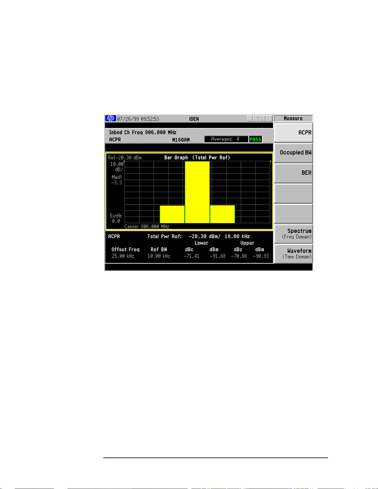
Results
The next figure shows an example result of adjacent channel power
measurements in the bar graph window. The power levels at both sides
of the carrier frequency are displayed in the graphic window and text
window.
Figure 3-1 Adjacent Channel Power Measurement Result - Bar Graph
Changing the Measurement Setup
The next table shows the factory default settings for adjacent channel
power measurements.
28 Chapter3

Making iDEN Measurements
Making the Adjacent Channel Power Measurement
Table 3-1 Adjacent Channel Power Measurement Defaults
Measurement Parameter Factory Default Condition
Average number 20, On
Average mode Exponential
Trigger source RF burst (inbound)
Limit Test On
Reference BW 18 kHz
Offset frequency 25.000 kHz
Offset bandwidth 10.000 kHz
Absolute limit 0.00 dBm
Fail Relative
Relative limit (carrier) −60 dB
Relative limit (PSD) −57.45 dB
Make sure the adjacent channel power measurement is selected under
the
Measure menu. The Meas Setup key accesses the menu which allows
you to modify the average number, average mode and trigger source for
this measurement as described in “Measurement Setup” earlier in this
chapter. However, the trigger source does not include
Video or Line. In
addition, the following parameters for adjacent channel power
measurements can be modified:
•
Limit Test - Allows you to toggle the limit test function between On
and Off. If set to On, Abs Lim and/or Rel Lim need to be specified to
execute pass/fail tests with the logical judgement under the
Fail key.
Pass/fail results are shown in the active display window with the
number of averages. In the text window, a red character F is shown
on the right side of each measurement result, either relative or
absolute, if it exceeds the limits with its logical judgement.
•
Ref BW - Allows you to enter a reference bandwidth ranging from 300
Hz to 20.0000 MHz with the best resolution of 1 Hz. When this
parameter is changed, the integration bandwidth Integ BW in the
summary data window changes to that value.
•
Offs & Limits - Allows you to access the menu to change the following
parameters for pass/fail tests:
Offset Freq - Allows you to store a frequency offset value. For
iDEN the offset for the measurement is specified as 25 kHz. The
offset selection is shown on the key label.
Offset BW - Allows you to select bandwidth of the carrier and
offset channels that you want to measure.
Chapter 3 29

Making iDEN Measurements
Making the Adjacent Channel Power Measurement
Abs Limit - Allows you to enter an absolute limit value ranging
from −200.00 to +50.00 dBm with 0.01 dB finest resolution.
Fail - Allows you to access the following menu to select one of the
logic keys for fail conditions between the measurement results
and the test limits:
AND - Fail is shown if one of the relative ACP measurement
results is larger than
Rel Lim AND the absolute ACP
measurement result is larger than
OR - Fail is shown if one of the relative ACP measurement
results is larger than
Rel Lim OR one of the absolute ACP
measurement results is larger than
Absolute - Fail is shown if one of the absolute ACP
measurement results is larger than
Relative - Failis shown if one of the relative ACP measurement
results is larger than
Rel Lim (Car)- Allows you to enter a limit value, relative to the
Rel Lim.
carrier, ranging from −200.00 to +50.00 dB with 0.01 dB finest
resolution.
Abs Limit.
Abs Limit.
Abs Limit.
Rel Lim (PSD)- Allows you to enter a limit value, relative to the
power spectral density, ranging from −200.00 to +50.00 dB with
0.01 dB finest resolution.
Troubleshooting Hints
This adjacent channel power ratio measurement can reveal degraded or
defective parts in the transmitter section of the UUT. The following
examples are those areas to be checked further.
• Some faults in the DC power supply control of the transmitter power
amplifier, RF power controller of the pre-power amplifier stage, or
I/Q control of the baseband stage
• Some degradation in the gain and output power level of the amplifier
due to the degraded gain control and/or increased distortion
• Some degradation of the amplifier linearity and other performance
characteristics
Power amplifiers are one of the final stage elements of a base or mobile
transmitter and are a critical part of meeting the important power and
spectral efficiency specifications. Since ACP measures the spectral
response of the amplifier to a complex wideband signal, it is a key
measurement linking amplifier linearity and other performance
characteristics to the stringent system specifications.
30 Chapter3

Making iDEN Measurements
Making the Bit Error Rate Measurement
Making the Bit Error Rate Measurement
Purpose
The BER test lets you test for bit errors in your iDEN signal. Prepare to
run the BER test by first reviewing the information in “Setting Up the
iDEN Mode” on page 11.
Measurement Method
The BER test takes data from the RF input and then performs analysis
on that data to find bit errors. It measures BER on all four channels.
The num frames softkey determines the number of 90 milli-second
frames that the BER test demodulates. Since each frame has multiple
slots, the BER test uses the 1st slot that contains data. If the data in
that slot matches one of the 16 transmission unit data words defined by
iDEN, the BER test displays the number of the WORD that it found.
The number of frames that were actually found is indicated.
Making the Measurement
NOTE The factory default settings provide an iDEN compliant measurement.
For special requirements, you may need to change some of the settings.
Press
return all parameters for the current measurement to their default
settings.
Press
The bit error rate will be measured on all four channels. To change any
of the measurement parameters from thefactory default values, refer to
the
for this measurement.
Meas Setup, More (1 of 2), Restore Meas Defaults at any time to
Measure, BER to immediately make a bit error rate measurement.
Meas Setup key and “Changing the Measurement Setup” on page 33
Chapter 3 31

Making iDEN Measurements
Making the Bit Error Rate Measurement
Results
By default, the BER test displays two traces. The BER test also
displays the following results at the bottom of the display:
• Bit error rate, shown as a percentage total for all frames
• Current frame BER, shown as a percentage
• Bits failed, which is the number of bits that failed
• Bits tested, which is the number of bits tested
• Frames found
• Frames tested
• Current identified word
The BER test computes the bit error rate as follows:
Equation 3-1 Bit Error Rate Calculation
Number of bits failed
BER (%)
--------------------------------------------------Number of bits tested
100%×=
The results, from all frames that were tested, are shown. It also shows
the number of frames successfully demodulated and the number of
frames tested.
The BER test changes the results as follows if it cannot demodulate a
frame:
Bits Failed is increased by half the number of bits in the frame.
Statistically, a pure noise signal should have a BER of 50%. Bits
Tested is increased by the number of bits in the frame. Found, shows
two numbers: the first number shows the number of frames
successfully demodulated; the second number shows the number of
frames tested. For example, Found: 4/15 frames means 15 frames
were tested. Of these frames, only 4 were successfully demodulated.
The other 11 frames could not be found. The sync, word, or pulse
were not found.
The results use some of the following terminology:
Word is the transmission data unit word that contained the symbol
with the bit errors.
Total is the total number of bit errors in the composite symbol.
32 Chapter3

Figure 3-2 Bit Error Rate Measurement Results
Making iDEN Measurements
Making the Bit Error Rate Measurement
Changing the Measurement Setup
Frames determines the number of frames used by each test. The
default is 16. The measurement requires n frames for demodulation
and BER measurement. One additional frame is acquired for a
preliminary carrier frequency estimation. For example, if
16, the BER test acquires 17 frames of data (n + 1), and then
searches for the first frame that it can demodulate. The
measurement demodulates the selected number of frames using the
specified trigger conditions.
Table 3-2 Bit Error Rate Measurement Defaults
Measurement Parameter Factory Default Condition
Frames 16
Trigger source Video (IF envelope)
Limit Test On
Bit error rate 5%
Frames is
Chapter 3 33

Making iDEN Measurements
Making the Occupied Bandwidth Measurement
Making the Occupied Bandwidth
Measurement
Purpose
To utilize the limited resource of radio frequency bands to provide as
many communication channels as possible, it is critical to measure and
control the occupied bandwidth transmitted from a mobile phone. This
occupied bandwidth is defined as the frequency bandwidth in which
99% of the total power is measured.
The occupied bandwidth of a mobile phone tends to be improved if its
adjacent channel power is reduced. To provide as many channels as
possible to meet the increasing number of subscribers, both of these
characteristics of a mobile phone need to be measured and analyzed for
further performance improvement.
Measurement Method
This is the frequency bandwidth in which 99% of the total power is
measured, based on Fast Fourier Transform (FFT) theory.
In the actual measuring process, first the total channel power is
measured using a sampling method. Then each power sample is
integrated up to 0.5% of the total power from the lowest and highest
frequency sides to determine the low and high limit frequencies. The
difference derived from these frequencies is the occupied bandwidth.
The measurement functions suchas averaging, trigger source,limit test
and limit need to be set up to make a measurement and pass/fail test.
The test results are displayed in the graphic window and in the text
window.
Making the Measurement
NOTE The factory default settings provide an iDEN compliant measurement.
For special requirements, you may need to change some of the settings.
Press
return all parameters for the current measurement to their default
settings.
Meas Setup, More (1 of 2), Restore Meas Defaults at any time to
Select the desired center frequency as described in “Changing the
Frequency Channel” on page 16.
Press
bandwidth measurement. To change any of the measurement
parameters from the factory default values, refer to “Changing the
Measurement Setup” on page 35 for this measurement.
34 Chapter3
Measure, Occupied BW to immediately make the occupied

Making the Occupied Bandwidth Measurement
Results
In the upper window the sampled power distribution is displayed with
0.5% frequency marker lines. The actual measured data of the occupied
bandwidth and the total channel power are shown in the lower window.
Figure 3-3 Occupied Bandwidth Measurement Results
Making iDEN Measurements
Changing the Measurement Setup
The next table shows the factory default settings for occupied
bandwidth measurements.
Chapter 3 35

Making iDEN Measurements
Making the Occupied Bandwidth Measurement
Table 3-3 Occupied Bandwidth Measurement Defaults
Measurement Parameter Factory Default Condition
Log Scale 10.00 dB/div
Avg Number 10, On
Avg Mode Repeat
Trigger Source Video (IF envelope)
% (percent) power 99%
Limit Test On
Limit 20.0 kHz
Make sure the occupied bandwidth measurement is selected under the
Measure menu. The Meas Setup key accesses the menu which allows you
to modify the averaging and trigger source for this measurement as
described in “Preparing for Measurements” earlier in this chapter. In
addition, the following occupied bandwidth measurement parameters
can be modified:
•
Limit Test - Allows you to toggle the limit test function between On
and Off. If set to On, the Limit key needs to be pressed to specify the
limit value. Pass/fail results are shown in the active display window
with the number of averages.
•
Limit - Allows you to specify the frequency limit value ranging from
10.000 to 60.000 kHz with 0.1 kHz resolution.
Troubleshooting Hints
36 Chapter3

Making iDEN Measurements
Making the Spectrum (Frequency Domain) Measurement
Making the Spectrum (Frequency Domain)
Measurement
Purpose
The spectrum measurement provides spectrum analysis capability for
the instrument. The control of the measurement was designed to be
familiar to those who are accustomed to using swept spectrum
analyzers.
This measurement is FFT (Fast Fourier Transform) based. The
FFT-specific parameters are located in the
available under basic mode spectrum measurements is an
I/Q window, which shows the I and Q signals in parameters of voltage
and time. The advantage of having an I/Q view available while in the
spectrum measurement is that it allows you to view complex
components of the same signal without changing settings or
measurements.
Advanced menu. Also
Measurement Method
The transmitter tester uses digital signal processing to sample the
input signal and convert it to the frequency domain. With the
instrument tuned to a fixed center frequency, samples are digitized at a
high rate, converted to I and Q components with DSP hardware, and
then converted to the frequency domain with FFT software.
Making the Measurement
NOTE The factory default parameters provide a good starting point.You will
likely want to change some of the settings. Press
2), Restore Meas Defaults at any time to return all parameters for the
current measurement to their default settings.
Press
Spectrum (Frequency Domain) the active measurement.
Tochange any of the measurement parameters from the factory default
values, refer to the “Changing the Measurement Setup” section for this
measurement.
Measure, Spectrum (Freq Domain) to immediately make
Meas Setup, More (1 of
Results
A display with both a spectrum window and an I/Q Waveform window
will appear when you activate a spectrum measurement. Use the
Window key to select a window, and the Zoom key to enlarge a window.
Chapter 3 37
Next

Making iDEN Measurements
Making the Spectrum (Frequency Domain) Measurement
Figure 1 Spectrum Measurement Result- Spectrum Window
38 Chapter3

Making iDEN Measurements
Making the Spectrum (Frequency Domain) Measurement
Changing the Measurement Setup
Table 1 Spectrum (Frequency Domain) Measurement Defaults
Measurement Parameter Factory Default Condition
Res BW 250.000 Hz
Averaging:
Avg Number
Avg Mode
Avg Type
Trigger Source RF Burst (Wideband)
25 On
Exp
Log-Pwr Avg (Video)
Measurement Time
(Service mode only)
Spectrum Window:
Span
Scale/Div - Amplitude Y Scale
I/Q Waveform Window:
Capture Time
Scale/Div - Amplitude Y Scale
Advanced
Pre-ADC BPF On
Pre-FFT Filter Flat
Pre-FFT BW 155.000 kHz (Auto)
FFT Window Flat Top (High AmptdAcc)
FFT Size:
Length Control
Min Points/RBW
Window Length
FFT Length
ADC Range Auto Peak
1.0 ms (Auto)
100.000 kHz
10.00 dB
15.06 ms
60 mV
Auto
1.300000
5648
32768
Data Packing Auto
ADC Dither Auto
Decimation 0 (Auto)
IF Flatness On
Chapter 3 39

Making iDEN Measurements
Making the Spectrum (Frequency Domain) Measurement
NOTE Parameters under the Advanced key seldom need to be changed. Any
changes from the default advanced values may result in invalid
measurement data.
Make sure the
the
Measure menu. Press the Meas Setup key to access a menu which
Spectrum (Freq Domain) measurement is selected under
allows you to modify the averaging, and trigger source for this
measurement (as described in the “Measurement Setup” section). In
addition, the following parameters can be modified:
•
Span - This key allows you to modify the frequency span. Changing
the span causes the bandwidth to change automatically, and will
affect data acquisition time.
•
Res BW - This feature sets the resolution bandwidth for the FFT, and
allows manual or automatic settings. A narrower bandwidth will
result in a longer data acquisition time. In Auto mode the resolution
bandwidth is set to Span/50 (2% of the span).
•
Advanced - The following FFT advanced features should be used only
if you are familiar with their operation. Changes from the default
values may result in invalid data.
Pre-ADC BPF - This key allows you to toggle the pre-ADC
bandpass filter to On or Off states. The pre-ADC bandpass filter
is useful for rejecting nearby signals, so that sensitivity within
the span range can be improved by increasing the ADC range
gain.
Pre-FFT Fltr - Allows you to toggle between
Gaussian. The pre-FFT filter defaults to a flat top filter which has
Flat (flat top) and
better amplitude accuracy. The Gaussian filter has better pulse
response.
Pre-FFT BW - The Pre-FFT bandwidth allows you to select
between a manual or an automatic setting. The pre FFTbandwidth filter can be set between 1 Hz and 10 MHz. In Auto
mode this bandwidth is nominally 50% wider than the span. This
bandwidth determines the ADC sampling rate.
40 Chapter3

Making iDEN Measurements
Making the Spectrum (Frequency Domain) Measurement
FFT Window - Allows you to access the following selection
menu. Unless you are familiar with FFT windows, use the flat top
filter (the default filter).
• Flat Top - Selects a filter for best amplitude accuracy, by
reducing scalloping error.
• Uniform - You can select to have no window active by using
the uniform setting.
• Hanning
• Hamming
• Gaussian - Selects a gaussian filter with an alpha of 3.5.
• Blackman
• Blackman Harris
• K-B 70dB / 90dB/ 110dB (Kaiser-Bessel) - Allows selection
of Kaiser-Bessel filters with sidelobes of −70, −90, or −110 dBc.
FFT Size - This menu contains the following features:
• Length Ctrl - This feature allows you to set the FFT and
window lengths either automatically or manually.
• Min Pts in RBW - This feature allows you to set the
minimum number of data points that will be used inside the
resolution bandwidth. This adjustment is only available if the
Length Ctrl key is set to Auto.
• Window Length - This feature allows you to enter the FFT
window length ranging from 8 to 1048576. This length
represents the actual quantity of I/Q samples that are
captured for processing by the FFT. This value can only be
entered if length control is set to Manual.
• FFT Length - This feature allows you to enter the FFT length
in the number of captured samples, ranging from 4096 to
1048576. The FFT length setting is automatically limited so
that it is equal or greater than the FFT window length setting.
Any amount greater than the window length is implemented
by zero-padding. This value can be entered only if length
control is set to Man (manual).
ADC Range - Allows you to access the following selection menu
to define one of the following ADC ranging functions:
• Auto - Select this to set the ADC range automatically. For
most FFT spectrum measurements, the auto feature should
not be selected. An exception is when measuring a signal
which is “bursty”, in which case auto can maximize the time
domain dynamic range, if FFT results are less important to
you than time domain results.
• Auto Peak - Select this to set the ADC range automatically to
the peak signal level. Auto peak is a compromise that works
well for both CW and burst signals.
Chapter 3 41

Making iDEN Measurements
Making the Spectrum (Frequency Domain) Measurement
• AutoPeakLock - Select this to hold the ADC range
automatically at the peak signal level. Auto peak lock is more
stable than auto peak for CW signals, but should not be used
for “bursty” signals.
• Manual - Allows you to access the selection menu:
+6 dB, +12 dB, +18 dB, +24 dB, to set the ADC range level. Also
−6dB, 0dB,
note that manual ranging is best for CW signals.
Data Packing - Allows you to access the following selection
menu to define one of the following data packing methods:
• Auto - Data is automatically packed. This is the default setting
and most recommended.
• Short (16 bit) - Data is packed by every 16 bits.
Medium (24 bit) - Data is packed by every 24 bits.
•
Long (32 bit) - Data is packed by every 32 bits.
•
ADC Dither - Allows you to toggle the ADC dither function between
Auto, On, and Off. When set to auto (the default), ADC dither will
be activated when a narrow bandwidth is being measured, and
deactivated when a wide bandwidth is being measured. “ADC
dither” refers to the introduction of noise to the digitized steps of
the analog-to-digital converter; the result is an improvement in
amplitude accuracy. Use of the ADC dither, however, reduces
dynamic range by approximately 3 dB.
Decimation - Allows you to toggle the decimation function between
Auto and Man, and to set the decimation value. Auto is the
preferred setting, and the only setting that guarantees alias-free
FFT spectrum measurements. If you are familiar with the
decimation feature, you can change the decimation value by
setting to
Man, but be aware that aliasing can result in higher
values.
IF Flatness - Allows you to toggle between On and Off. When
toggled to
On (the default), the IF flatness feature causes
background amplitude corrections to be performed on the FFT
spectrum. The
Off setting is used for adjustment and
troubleshooting the transmitter tester.
42 Chapter3

Making iDEN Measurements
Making the Spectrum (Frequency Domain) Measurement
Changing the View
View/Trace menu keys are used to activate a view of a measurement
with preset X and Y scale parameters, called a “window”. Using the X
and Y Scale keys you can then modify these parameter settings. You
can also activate specific traces, using the
Windows Available for Spectrum Measurements
The spectrum and the I/Q windows can be viewed at the same time, or
individually. You can use the
Next Window and Zoom keys to move
between these different views.
Spectrum window Select this window if you want to view frequency
and power. Changes to frequency span or power will sometimes affect
data acquisition.
I/Q Waveform window. Select this window to view the I and Q signal
characteristics of the current measurement in parameters of voltage
and time.
Trace Display menu key.
NOTE For the widest spans the I/Q window becomes just “ADC time domain
samples”, because the I/Q down-conversion is no longer in effect.
Using the Markers
The Marker front-panel key accesses the menu to configure the markers.
If you want to use the marker function in the I/Q window, press
View/Trace, I/Q Waveform, Marker, Trace, IQ Waveform.
Select 1 2 3 4 - Allows you to activate up to four markers with the
•
corresponding numbers, respectively. The selected number is
underlined and its function is defined by pressing the
The default is 1.
• Normal - Allows you to activate the selected marker to read the
frequency and amplitude of the marker position on the spectrum
trace, for example, which is controlled by the
Delta - Allows you to read the differences in frequencies and
•
RPG knob.
amplitudes between the selected marker and the next.
• Function Off - Allows you to define the selected marker function to be
Band Power, Noise,orOff. The default is Off. If set to Band Power,you
need to select
Delta.
Function key.
Trace Spectrum - Allows you to place the selected marker on the
•
Spectrum, Spectrum Avg, or I/Q Waveform trace. The default is
Spectrum.
Chapter 3 43

Making iDEN Measurements
Making the Spectrum (Frequency Domain) Measurement
• Off - Allows you to turn off the selected marker.
Shape Diamond - Allows you to access the menu to define the selected
•
marker shape to be a
a
Diamond.
Marker All Off - Allows you to turn off all of the markers.
•
Diamond, Line, Square, or Cross. The default is
The front panel
Search key performs a peak search when pressed. A
marker will automatically be activated at the highest peak.
Band Power
A band power measurement using the markers calculates the average
power between two adjustable markers. To make a band power
measurement:
Press the
Press
spectrum signal. Press the
Marker key.
Trace, Spectrum to activate a marker on the instantaneous
Spectrum Avg key to activate a marker on
the average spectrum trace.
Press Function, Band Power.
Two marker lines are activated at the extreme left side of the
horizontal scale. Press Normal and move marker 1 to the desired
place by rotating the
Press
Delta to bring marker 2 to the same place as marker 1.
Move marker 1 to the other desired position by rotating the
RPG knob.
RPG
knob. Band power measures the average power between the two
markers. When the band power markers are active, the results are
shown in the results window as Mean Pwr(Between Mks).When the
band power function is off the results window reads Mean Pwr
(Entire Trace).
Troubleshooting Hints
Changes made by the user to advanced spectrum settings, particularly
to ADC range settings, can inadvertently result in spectrum
measurements that are invalid and cause error messages to appear.
Care needs to be taken when using advanced features.
44 Chapter3

Making iDEN Measurements
Making the Waveform (Time Domain) Measurement
Making the Waveform (Time Domain)
Measurement
Purpose
The waveform measurement is a generic measurement for viewing
waveforms in the time domain. This measurement is how the
instrument performs the zero span functionality found in traditional
spectrum analyzers. Also available under basic mode waveform
measurements is an I/Q window, which shows the I and Q signal in
parameters of voltage and time. The advantage of having an I/Q view
available while in the waveform measurement is that it allows you to
view complex components of the same signal without changing settings
or measurements.
The waveform measurement can be used to perform general purpose
power measurements to a high degree of accuracy.
Measurement Method
The transmitter tester makes repeated power measurements at a set
frequency, similar to the way a swept-tuned spectrum analyzer makes
zero span measurements. The input analog signal is converted to a
digital signal, which then is processed into a representation of a
waveformmeasurement. The transmitter tester relies on a high rates of
sampling to create an accurate representation of a time domain signal.
Making the Measurement
NOTE The factory default parameters provide a good starting point.You will
likely want to change some of the settings. Press
2), Restore Meas Defaults at any time to return all parameters for the
current measurement to their default settings.
Press
Waveform (Time Domain) the active measurement.
Tochange any of the measurement parameters from the factory default
values, refer to the “Changing the Measurement Setup” section for this
measurement.
Measure, Waveform (Time Domain) to immediately make
Meas Setup, More (1 of
Chapter 3 45

Making iDEN Measurements
Making the Waveform (Time Domain) Measurement
Results
Figure 2 Waveform Measurement Results- RF Envelope Window
46 Chapter3

Making the Waveform (Time Domain) Measurement
Changing the Measurement Setup
Table 2 Waveform (Time Domain) Measurement Defaults
Measurement Parameter Factory Default Condition
View/Trace RF Envelope
Sweep Time 15.00 ms
Res BW 100.000 kHz
Averaging:
Avg Number
Avg Mode
Avg Type
Trigger Source RF Burst
RF Envelope Window:
Amplitude Y Scale
Scale/Div
Reference
10 Off
Exp
Pwr Avg (RMS)
10.00 dB
0.00 dBm (Top)
Making iDEN Measurements
I/Q Waveform Window:
Amplitude Y Scale
Scale/Div
Reference
Advanced
Pre-ADC BPF Off
RBW Filter Gaussian
ADC Range Auto
Data Packing Auto
ADC Dither Off
Decimation Off
NOTE Parameters that are under the Advanced key seldom need to be
100.0 mv
0.00 V (Ctr)
changed. Any changes from the default values may result in invalid
measurement data.
Chapter 3 47

Making iDEN Measurements
Making the Waveform (Time Domain) Measurement
Make sure the Waveform (Time Domain) measurement is selected under
the
Measure menu. Press the Meas Setup key to access a menu which
allows you to modify the averaging, and trigger source for this
measurement (as described in the “Measurement Setup” section). In
addition, the following parameters can be modified:
•
Sweep Time - This key allows you to select the measurement
acquisition time. It is used to specify the length of the time capture
record. Values between 10 µs and 50 s can be entered, depending
upon the resolution bandwidth setting.
•
Res BW - This key sets the measurement bandwidth. A larger
bandwidth results in a larger number of acquisition points and
reduces the maximum allowed for sweep time. You can enter values
between 10 Hz. and 7.5 MHz.
•
Advanced menu key. This key accesses the features listed below.
Pre-ADC BPF - This key allows you to toggle the pre-ADC
bandpass filter to On or Off states. The pre-ADC bandpass filter
is useful for rejecting nearby signals, so that sensitivity within
the span range can be improved by increasing the ADC range
gain
RBW Filter - This key toggles to select a flat top or a Gaussian
resolution bandwidth filter. A Gaussian filter provides more even
time domain response, particularly for bursts. A flat top filter
provides a flatter bandwidth but is less accurate for pulse
responses. A flat top filter also requires less memory and allows
longer data acquisition times. For most waveform applications,
the Gaussian filter is recommended, and it is the default filter for
waveform measurements.
ADC Range -.Allows you to access the following selection menu to
define one of the following ADC ranging functions:
•
Auto - This key causes the instrument to automatically adjust
the signal range for optimal measurement results.
•
AutoPeak - This key causes the instrument to continuously
seek the highest peak signal.
•
AutoPeakLock - This key causes the instrument to adjust the
range for the highest peak signal it identifies, and retains the
range settings determined by that peak signal, even when the
peak signal is no longer present.
•
Manual - Allows you to access the selection menu: −6 dB, 0 dB,
+6 dB, +12 dB, +18 dB, +24 dB, to set the ADC range level. Also
note that manual ranging is best for CW signals.
48 Chapter3

Making iDEN Measurements
Making the Waveform (Time Domain) Measurement
Data Packing - Allows you to access the following selection menu to
define one of the following data packing methods:
•
Auto - Data is automatically packed. This is the default setting
and most recommended.
• Short (16 bit) - Data is packed by every 16 bits.
• Medium (24 bit) - Data is packed by every 24 bits.
• Long (32 bit) - Data is packed by every 32 bits.
ADC Dither - Allows you to toggle the ADC dither function
between
On and Off. Activation of the ADC dither results in better
amplitude linearity and resolution in low level signals. However,
it also results in reduced dynamic range. ADC dither is set to Off
by default.
Decimation - Allows you to toggle the decimation function
between
On and Off and to set the decimation value. Decimation
allows longer acquisition times for a given bandwidth by
eliminating data points. Long time captures can be limited by the
transmitter tester data acquisition memory. Decimation numbers
1 to 4 describe the factor by which the number of points are
reduced. A decimation figure of 1, which results in no data point
reduction, is the default.
Chapter 3 49

Making iDEN Measurements
Making the Waveform (Time Domain) Measurement
Changing the View
The View/Trace menu keys are used to activate a view of a measurement
with preset X and Y scale parameters; this view is called a “window.”
Using the X and Y scale keys, you can then modify these parameters.
You can also activate traces, using the
Traces Display menu key.
Windows Available for Waveform Measurements
RF Envelope window. Select this window if you want to view
power (in dBm) vs. time. Remember that data acquisition will be
affected when you change the sweep time.
I/Q Waveform window. Select this window to view the I and Q signal
characteristics of the current measurement in parameters of voltage
and time.
Using the Markers
The Marker front-panel key accesses the menu to configure the markers.
If you want to use the marker function in the I/Q window, press
View/Trace, I/Q Waveform, Marker, Trace, IQ Waveform.
Select 1 2 3 4 - Allows you to activate up to four markers with the
•
corresponding numbers, respectively. The selected number is
underlined and its function is defined by pressing the
Function key.
The default is 1.
• Normal - Allows you to activate the selected marker to read the
frequency and amplitude of the marker position on the spectrum
trace, for example, which is controlled by the
Delta - Allows you to read the differences in frequencies and
•
RPG knob.
amplitudes between the selected marker and the next.
• Function Off - Allows you to define the selected marker function to be
Band Power, Noise,orOff. The default is Off. If set to Band Power,you
need to select
Trace Spectrum - Allows you to place the selected marker on the
•
Spectrum, Spectrum Avg, or I/Q Waveform trace. The default is
Spectrum.
Off - Allows you to turn off the selected marker.
•
Shape Diamond - Allows you to access the menu to define the selected
•
marker shape to be a
a
Diamond.
Delta.
Diamond, Line, Square, or Cross. The default is
Marker All Off - Allows you to turn off all of the markers.
•
The front panel
Search key performs a peak search when pressed. A
marker will automatically be activated at the highest peak.
50 Chapter3

Making iDEN Measurements
Making the Waveform (Time Domain) Measurement
NOTE In the Waveform measurement, the Mean Pwr (Entire Trace) value
plus the Pk-to-Mean value will sum to equal the current Max Pt. value
as shown in the data window below the RF Envelope display. If you do a
marker peak search (
Search) with averaging turned off, the marker will
find the same maximum point. However, if you turn averaging on, the
Pk-to-Mean value will use the highest peak found for any acquisition
during averaging, while the marker peak will look for the peak of the
display, which is the result of n-averages. This will usually result in
differing values for the maximum point.
Band Power
A band power measurement using the markers calculates the average
power between two adjustable markers. To make a band power
measurement:
Press the
Press Function,
Marker key.
Band Power.
Two marker lines are activated at the extreme left side of the
horizontal scale. Press Normal and move marker 1 to the desired
place by rotating the
Press
Delta to bring marker 2 to the same place as marker 1.
Move marker 1 to the other desired position by rotating the
RPG knob.
RPG
knob. Band power measures the average power between the two
markers. When the band power markers are active, the results are
shown in the results window as Mean Pwr(Between Mks).When the
band power function is off the results window reads Mean Pwr
(Entire Trace).
Troubleshooting Hints
Changes made by the user to advanced waveform settings can
inadvertently result in measurements that are invalid and cause error
messages to appear. Care needs to be taken when using advanced
features.
Chapter 3 51

Making iDEN Measurements
Making the Waveform (Time Domain) Measurement
52 Chapter3

4 iDEN Specifications
All specifications apply over 0 °C to +55 °C, except when otherwise
specified. The instrument will meet its specifications after 2 hours of
storage at a constant temperature, within the operating temperature
range, 1 hour after the instrument is turned on and within 24 hours
after “Align All Now” has been run. The specifications for each
measurement apply for the measurement’s factory default setup.
53

iDEN Specifications
Measurements
Measurements
Measurement Specifications Supplemental Information
Adjacent Channel Power Ratio
Carrier power range at UUT
Mobile station
Carrier power range at RF Input +26 to −40 dBm
Adjacent channel power ratio range
at 25 kHz offset 0 to −70 dBc, characteristic
Resolution 0.01 dB
a
+46 to −20 dBm With ≥20 dB external atten.
For 18 kHz reference BW and
10 kHz offset BW.
a. UUT = Unit Under Test
Measurement Specifications Supplemental Information
Occupied Bandwidth
Carrier power range at UUT
Mobile station +46 to −20 dBm With ≥20 dB external atten.
Carrier power range at RF Input +26 to −40 dBm
Frequency resolution of occupied
bandwidth 10 Hz
Frequency accuracy of occupied
bandwidth 300 Hz
Frequency resolution of carrier
frequency error 10 Hz
Frequency accuracy of carrier
frequency error
54 Chapter4
±50 Hz
Excludes frequency reference

iDEN Specifications
Measurements
Measurement Specifications Supplemental Information
M16QAM Bit Error Rate
Carrier power range at UUT +46 to −20 dBm With 20 dB external atten.
Carrier power range at RF Input +26 to −40 dBm
Minimum BER < 1%
Frequency error:
Input frequency error range
Frequency accuracy of carrier
frequency
Measurement Specifications Supplemental Information
±5 kHz, characteristic
±10 Hz, characteristic
Waveform (Time Domain) See“WaveformMeasurement”
under Transmitter Tester
Specifications
(Measurements)
Measurement Specifications Supplemental Information
Spectrum See “Spectrum Measurement”
under Transmitter Tester
Specifications
(Measurements)
Chapter 4 55

iDEN Specifications
Frequency
Frequency
Measurements Specifications Supplemental Information
In-Band Frequency Range 700 to 1600 MHz
56 Chapter4

iDEN Specifications
General
General
Measurements Specifications Supplemental Information
Trigger
Trigger source RF burst (wideband), Video (IF
envelope), Ext Front, Ext Rear,
Frame Timer. Actual available
choices are dependent on
measurement.
Default is video (IF envelope)
for Occupied BW and BER.
It is RF burst (wideband) for
ACPR.
Trigger delay
Range
Accuracy
Resolution
−500 to +500 ms
±33 ns
33 ns
External trigger input
Level
Impedance
−5 to +5V, characteristic
>10 kΩ, nominal
Chapter 4 57

iDEN Specifications
General
58 Chapter4

5 iDEN Programming Commands
These commands are only available when the iDEN mode has been
selected using INSTrument:SELect. If iDEN mode is selected,
commands that are unique to another mode are not available.
59

iDEN Programming Commands
SCPI Command Subsystems
SCPI Command Subsystems
CALCulate on page 61
CONFigure on page 78
DISPlay on page 79
FETCh on page 83
MEASure on page 84
READ on page 96
SENSe on page 97
60 Chapter5

iDEN Programming Commands
CALCulate Subsystem
CALCulate Subsystem
This subsystem is used to perform post-acquisition data processing. In
effect, the collection of new data triggers the CALCulate subsystem. In
this instrument, the primary functions in this subsystem are markers
and limits.
Adjacent Channel Power—Limit Test
:CALCulate:ACP:LIMit:STATe OFF|ON|0|1
:CALCulate:ACP:LIMit:STATe?
Turn limit test on or off.
Factory Preset
and *RST: On
Remarks: You must be in Basic, cdmaOne, iDEN mode to use this
command. Use INSTrument:SELect to set the mode.
Bit Error Rate—Frame Count
:CALCulate:BER:FRAMes <integer>
:CALCulate:BER:FRAMes?
Indicates the number of frames to be used for calculating the bit error
rate.
Factory Preset
and *RST: 16
Factory Preset
and *RST: 1 to 1024 frames
Remarks: You must be in the iDEN mode to use this command.
Use INSTrument:SELect to set the mode.
History: Version A.03.00 or later
Chapter 5 61

iDEN Programming Commands
CALCulate Subsystem
Bit Error Rate—Error Limit
:CALCulate:BER:LIMit:ERATe <percent>
:CALCulate:BER:LIMit:ERATe?
Set the percent error limit on the bit error rate.
Factory Preset
and *RST: 5%
Range: 0.1 to 20%
Default Unit: Hz
Remarks: You must be in the iDEN mode to use this command.
Use INSTrument:SELect to set the mode.
History: Version A.03.00 or later
Bit Error Rate—Limit Testing
:CALCulate:BER:LIMit:STATe OFF|ON|0|1
:CALCulate:BER:LIMit:STATe?
Turn limit testing on or off.
Factory Preset
and *RST: On
Remarks: You must be in the iDEN mode to use this command.
Use INSTrument:SELect to set the mode.
History: Version A.03.00 or later
Query the Current Measurement Status
:CALCulate:CLIMits:FAIL?
Checks if the current measurement is outside its limits. It returns a 0
(zero) if it is passing or a 1 (one) if it is failing.
Front Panel
Access: None
62 Chapter5

iDEN Programming Commands
CALCulate Subsystem
Data Query
:CALCulate:DATA[n]?
Returns the designated measurement data for the currently selected
measurement and sub-opcode.
n = any valid sub-opcode for the current measurement. See the
“MEASure Group of Commands” on page 84 for information on the data
that can be returned for each measurement.
Calculate/Compress Trace Data Query
:CALCulate:DATA[n]:COMPress?
MAXimum|MEAN|MINimum|RMS|SAMPle|SDEViation|CFIT
{,<soffset>}{,<length>}{,<roffset>}
Returns the designated trace data for the currently selected
measurement. The command can be used with sub-opcodes (n) for
measurement results that are trace data. See the following table.
This command is used to compress/decimate a long trace to extract the
desired data and only return to the computer the necessary data. A
typical example would be to acquire N bursts of GSM data and return
the mean power of each burst.
The command can also be used to identify the best curve fit for the data.
Curve Fit - applies curve fitting routines to the data. Where
<soffset> and <length> are required, and <roffset> is an optional
parameter for the desired order of the curve equation. The query will
return the following values: the x-offset (in points) and the curve
coefficients ((order + 1) values).
<Start offset> - is an optional integer. It specifies the amount of data,
at the beginning of the trace, that will be ignored before the
decimation process starts. It is an integer index (that starts counting
at zero) for all the elements in the trace. The default value is zero.
<Length> - is an optional integer that defines how many trace
elements will be compressed into one value. This parameter has a
default value equal to the current trace length.
<Repeat offset> - is an optional real number.It defines the beginning
of the next field of trace elements to be compressed. This is relative
to the beginning of the previous field. This parameter has a default
value equal to the <length> variable. Select a number such that
repeated additions will round to the correct starting index.
Chapter 5 63

iDEN Programming Commands
CALCulate Subsystem
Example: To query the mean power of a set of GSM bursts:
1. Set the waveform measurement sweep time to
acquire the required number of bursts.
2. Set the triggers such that acquisition happens at a
known position relative to a burst.
3. Then query the mean burst levels using,
CALC:DATA2:COMP? MEAN,62,1315,1442.3 (These
parameter values correspond to GSM signals.)
Remarks: The optional parameters must be entered in the
specified order. If you want to specify <length>, you
must also specify <soffset> or it’s default. (e.g.
CALC:DATA2:COMP? MEAN,62,1315
This command uses the data setting specified by the
FORMat:DATA command and can return binary or
ascii data.
History: Added in revision A.03.00 and later
Measurement Available Traces
ACP - adjacent channel power
(Basic, cdmaOne, cdma2000,
W-CDMA, iDEN, NADC, PDC modes)
BER - bit error rate
(iDEN mode)
CDPower - code domain power
(cdmaOne mode)
CDPower - code domain power
(W-CDMA mode)
CHPower - channel power
(Basic, cdmaOne, cdma2000,
W-CDMA mode)
Markers
Available?
no traces no markers
no traces no markers
POWer (n=2)
TIMing (n=3)
PHASe (n=4)
a
a
a
CDPower (n=2)
EVM (n=4)
MERRor (n=5)
PERRor (n=6)
SPOWer (n=8)
a
a
a
a
SPECtrum (n=2)
a
a
yes
yes
no markers
CSPur - spurs close
(cdmaOne mode)
SPECtrum (n=2)
ULIMit (n=3)
a
a
yes
64 Chapter5

iDEN Programming Commands
CALCulate Subsystem
Measurement Available Traces
EVM - error vector magnitude
(NADC, PDC modes)
EVMQpsk - QPSK error vector
magnitude
(cdma2000, W-CDMA modes)
OBW - occupied bandwidth
(iDEN, PDC modes)
ORFSpectrum - output RF spectrum
(GSM mode)
PFERror - phase and frequency error
(GSM mode)
EVM (n=2)
MERRor (n=3)
PERRor (n=4)
EVM (n=2)
MERRor (n=3)
PERRor (n=4)
a
a
a
a
a
a
no traces
RFEModulation
a
(n=2)
RFESwitching
a
(n=3)
PERRor (n=2)
PFERror (n=3)
RFENvelope (n=4)
a
a
Markers
Available?
yes
yes
no markers
no markers
yes
a
PSTatistic - power statistics CCDF
(cdma2000, W-CDMA modes)
PVTime - power versus time
(GSM, Service modes)
RHO - modulation quality
(cdmaOne, cdma2000, W-CDMA
mode)
TSPur - transmit band spurs
(GSM mode)
TXPower - transmit power
(GSM mode)
MEASured (n=2)
GAUSsian (n=3)
a
REFerence (n=4)
RFENvelope (n=2)
UMASK (n=3)
LMASK (n=4)
EVM (n=2)
MERRor (n=3)
PERRor (n=4)
a
a
a
a
a
SPECtrum (n=2)
ULIMit (n=3)
a
RFENvelope (n=2)
IQ (n=8)
a
a
yes
a
a
yes
yes
a
yes
a
yes
Chapter 5 65

iDEN Programming Commands
CALCulate Subsystem
Measurement Available Traces
SPECtrum - (frequency domain)
(all modes)
WAVEform - (time domain)
(all modes)
RFENvelope (n=2)
for Service mode
IQ (n=3)
SPECtrum (n=4)
ASPectrum (n=7)
RFENvelope (n=2)
IQ (n=8)
a
a
a
a
a
a
Markers
Available?
yes
yes
a. The n number indicates the sub-opcode that corresponds to this
trace. Detailed descriptions of the trace data can be found in the
MEASure subsystem documentation by looking up the
sub-opcode for the appropriate measurement.
Calculate Peaks of Trace Data
:CALCulate:DATA[n]:PEAKs?
<threshold>,<excursion>[,AMPLitude|FREQuency|TIME]
Returns a list of peaks for the designated trace data n for the currently
selected measurement. The peaks must meet the requirements of the
peak threshold and excursion values.
The command can be used with sub-opcodes (n) for any measurement
results that are trace data. See the table above. Subopcode n=0, raw
trace data cannot be searched for peaks. Both real and complex traces
can be searched, but complex traces are converted to magnitude in
dBm.
Threshold - is the level below which trace data peaks are ignored
Excursion - To be defined as a peak, the signal must rise above the
threshold by a minimum amplitude change. Excursion is measured
from the lowest point above the threshold (of the rising edge of the
peak), to the highest signal point that begins the falling edge.
Amplitude - lists the peaks in order of descending amplitude, so the
highest peak is listed first. This is the default peak order listing if
the optional parameter is not specified.
Frequency - lists the peaks in order of occurrence, left to right across
the x-axis
Time - lists the peaks in order of occurrence, left to right across the
x-axis
66 Chapter5

iDEN Programming Commands
CALCulate Subsystem
Example: Select the spectrum measurement.
Use CALC:DATA4:PEAK? -40,10,FREQ to identify the
peaks above -40 dBm, with excursions of at least 10 dB,
in order of increasing frequency.
Query Results: Returns a list of floating-point numbers. The first value
in the list is the number of peak points that follow. A
peak point consists of two values: a peak amplitude
followed by the its corresponding frequency (or time).
If no peaks are found the peak list will consist of only
the number of peaks, (0).
The peak list is limited to 100 peaks. Peaks in excess of
100 are ignored.
Remarks: This command uses the data setting specified by the
FORMat:DATA command and can return real 32-bit,
real 64-bit, or ASCII data. The default data format is
ASCII.
History: Added in revision A.03.00 and later
Chapter 5 67

iDEN Programming Commands
CALCulate Subsystem
CALCulate:MARKers Subsystem
Markers can be put on your displayed measurement data to supply
information about specific points on the data. Some of the things that
markers can be used to measure include: precise frequency at a point,
minimum or maximum amplitude, and the difference in amplitude or
frequency between two points.
When using the marker commands you must specify the measurement
in the SCPI command. We recommend that you use the marker
commands only on the current measurement. Many marker commands
will return invalid results, when used on a measurement that is not
current. (This is true for commands that do more than simply setting or
querying an instrument parameter.) No error is reported for these
invalid results.
You must make sure that the measurement is completed before trying
to query the marker value. Using the MEASure or READ command,
before the marker command, forces the measurement to complete
before allowing the next command to be executed.
Each measurement has its own instrument state for marker
parameters. Therefore, if you exit the measurement, the marker
settings in each measurement are saved and are then recalled when
you change back to that measurement.
iDEN Mode - <measurement> key words
• ACP - no markers
• BER - no markers
• OBW - no markers
• SPECtrum - markers available
• WAVeform - markers available
Example:
Suppose you are using the Spectrum measurement. Toposition marker
2 at the maximum peak value, of the trace that marker 2 is currently
on, the command is:
:CALCulate:SPECtrum:MARKer2:MAXimum
You must make sure that the measurement is completed before trying
to query the marker value. Using the MEASure or READ command,
before the marker command, forces the measurement to complete
before allowing the next command to be executed.
68 Chapter5

iDEN Programming Commands
CALCulate Subsystem
Markers All Off on All Traces
:CALCulate:<measurement>:MARKer:AOFF
Turns off all markers on all the traces.
Example: CALC:SPEC:MARK:AOFF
Remarks: The keyword for the current measurement must be
specified in the command. (Some examples include:
SPECtrum, WAVeform)
Front Panel
Access:
Marker, More, Marker All Off
Marker Function
:CALCulate:<measurement>:MARKer[1]|2|3|4:FUNCtion
BPOWer|NOISe|OFF
:CALCulate:<measurement>:MARKer[1]|2|3|4:FUNCtion?
Selects the type of marker for the specified marker. A particular
measurement may not have all the types of markers that are commonly
available.
The marker must have already been assigned to a trace. Use
:CALCulate:<measurement>:MARKer[1]|2|3|4:TRACe to assign a
marker to a particular trace.
Band Power − is the integrated power between the two markers for
traces in the frequency domain and is the mean power between the
two markers for traces in the time domain.
Noise − is the noise power spectral density in a 1 Hz bandwidth. It is
averaged over 32 horizontal trace points.
Off − turns off the marker functions
Example: CALC:SPEC:MARK3:FUNC Noise
Remarks: The keyword for the current measurement must be
specified in the command. (Some examples include:
SPECtrum, WAVeform)
Front Panel
Access:
Marker, Marker Function
Chapter 5 69

iDEN Programming Commands
CALCulate Subsystem
Marker Function Result
:CALCulate:<measurement>:MARKer[1]|2|3|4:FUNCtion:RESult?
Quires the result of the currently active marker function. The
measurement must be completed before querying the marker.A
particular measurement may not have all the types of markers
available.
The marker must have already been assigned to a trace. Use
:CALCulate:<measurement>:MARKer[1]|2|3|4:TRACe to assign a
marker to a particular trace.
Example: CALC:SPEC:MARK:FUNC:RES?
Remarks: The keyword for the current measurement must be
specified in the command. (Some examples include:
SPECtrum, WAVeform)
Front Panel
Access:
Marker, Marker Function
Marker Peak (Maximum) Search
:CALCulate:<measurement>:MARKer[1]|2|3|4:MAXimum
Places the selected marker on the highest point on the trace that is
assigned to that particular marker number.
The marker must have already been assigned to a trace. Use
:CALCulate:<measurement>:MARKer[1]|2|3|4:TRACe to assign a
marker to a particular trace.
Example: CALC:SPEC:MARK1:MAX
Remarks: The keyword for the current measurement must be
specified in the command. (Some examples include:
SPECtrum, WAVeform)
Front Panel
Access: Search
70 Chapter5

iDEN Programming Commands
CALCulate Subsystem
Marker Peak (Minimum) Search
:CALCulate:<measurement>:MARKer[1]|2|3|4:MINimum
Places the selected marker on the lowest point on the trace that is
assigned to that particular marker number.
The marker must have already been assigned to a trace. Use
:CALCulate:<measurement>:MARKer[1]|2|3|4:TRACe to assign a
marker to a particular trace.
Example: CALC:SPEC:MARK2:MIN
Remarks: The keyword for the current measurement must be
specified in the command. (Some examples include:
SPECtrum, WAVeform)
Front Panel
Access: None
Marker Mode
:CALCulate:<measurement>:MARKer[1]|2|3|4:MODE
POSition|DELTa
:CALCulate:<measurement>:MARKer[1]|2|3|4:MODE?
Selects the type of marker to be a normal position-type marker or a
delta marker.A specific measurement may not have both types of
markers. For example, several measurements only have position
markers.
The marker must have already been assigned to a trace. Use
:CALCulate:<measurement>:MARKer[1]|2|3|4:TRACe to assign a
marker to a particular trace.
Example: CALC:SPEC:MARK:MODE DELTA
Remarks: For the delta mode only markers 1 and 2 are valid.
The keyword for the current measurement must be
specified in the command. (Some examples include:
SPECtrum, WAVeform)
Front Panel
Access:
Marker, Marker [Delta]
Chapter 5 71

iDEN Programming Commands
CALCulate Subsystem
Marker On/Off
:CALCulate:<measurement>:MARKer[1]|2|3|4[:STATe] OFF|ON|0|1
:CALCulate:<measurement>:MARKer[1]|2|3|4[:STATe]?
Turns the selected marker on or off.
The marker must have already been assigned to a trace. Use
:CALCulate:<measurement>:MARKer[1]|2|3|4:TRACe to assign a
marker to a particular trace.
Example: CALC:SPEC:MARK2: on
Remarks: The keyword for the current measurement must be
specified in the command. (Some examples include:
SPECtrum, AREFerence, WAVeform)
The WAVeform measurement only has two markers
available.
Front Panel
Access: M
arker, Select then Marker Normal or Marker On Off
Marker to Trace
:CALCulate:<measurement>:MARKer[1]|2|3|4:TRACe <trace_name>
:CALCulate:<measurement>:MARKer[1]|2|3|4:TRACe?
Assigns the specified marker to the designated trace. Not all types of
measurement data can have markers assigned to them.
Example: With the WAVeform measurement selected, a valid
command is CALC:SPEC:MARK2:TRACE rfenvelope.
Range: The names of valid traces are dependent upon the
selected measurement. See the following table for the
available trace names. The trace name assignment is
independent of the marker number.
Remarks: The keyword for the current measurement must be
specified in the command. (Some examples include:
SPECtrum, WAVeform)
Front Panel
Access:
Measurement Available Traces
Marker, Marker Trace
Markers
Available?
ACP - adjacent channel power
(Basic, cdmaOne, cdma2000,
W-CDMA, iDEN, NADC, PDC modes)
72 Chapter5
no traces no markers

iDEN Programming Commands
CALCulate Subsystem
Measurement Available Traces
BER - bit error rate
(iDEN mode)
CDPower - code domain power
(cdmaOne mode)
CDPower - code domain power
(W-CDMA mode)
CHPower - channel power
(Basic, cdmaOne, cdma2000,
W-CDMA mode)
CSPur - spurs close
(cdmaOne mode)
Markers
Available?
no traces no markers
POWer (n=2)
TIMing (n=3)
PHASe (n=4)
a
a
a
CDPower (n=2)
EVM (n=4)
MERRor (n=5)
PERRor (n=6)
SPOWer (n=8)
a
a
a
a
SPECtrum (n=2)
SPECtrum (n=2)
ULIMit (n=3)
a
a
a
a
yes
yes
no markers
yes
EVM - error vector magnitude
(NADC, PDC modes)
EVMQpsk - QPSK error vector
magnitude
(cdma2000, W-CDMA modes)
OBW - occupied bandwidth
(iDEN, PDC modes)
ORFSpectrum - output RF spectrum
(GSM mode)
PFERror - phase and frequency error
(GSM mode)
EVM (n=2)
MERRor (n=3)
PERRor (n=4)
EVM (n=2)
MERRor (n=3)
PERRor (n=4)
a
a
a
a
a
a
no traces
RFEModulation
a
(n=2)
RFESwitching
a
(n=3)
PERRor (n=2)
PFERror (n=3)
RFENvelope (n=4)
a
a
yes
yes
no markers
no markers
yes
a
Chapter 5 73

iDEN Programming Commands
CALCulate Subsystem
Measurement Available Traces
PSTatistic - power statistics CCDF
(cdma2000, W-CDMA modes)
PVTime - power versus time
(GSM, Service modes)
RHO - modulation quality
(cdmaOne, cdma2000, W-CDMA
mode)
TSPur - transmit band spurs
(GSM mode)
TXPower - transmit power
(GSM mode)
MEASured (n=2)
GAUSian (n=3)
a
REFerence (n=4)
RFENvelope (n=2)
UMASK (n=3)
LMASK (n=4)
EVM (n=2)
MERRor (n=3)
PERRor (n=4)
a
a
a
a
a
SPECtrum (n=2)
ULIMit (n=3)
a
RFENvelope (n=2)
IQ (n=8)
a
Markers
Available?
a
yes
a
a
yes
yes
a
yes
a
yes
SPECtrum - (frequency domain)
(all modes)
WAVEform - (time domain)
(all modes)
RFENvelope (n=2)
for Service mode
IQ (n=3)
a
SPECtrum (n=4)
ASPectrum (n=7)
RFENvelope (n=2)
IQ (n=8)
a
a
yes
a
a
a
yes
a. The n number indicates the sub-opcode that corresponds to this
trace. Detailed descriptions of the trace data can be found in the
MEASure subsystem documentation by looking up the
sub-opcode for the appropriate measurement.
74 Chapter5

iDEN Programming Commands
CALCulate Subsystem
Marker X Value
:CALCulate:<measurement>:MARKer[1]|2|3|4:X <param>
:CALCulate:<measurement>:MARKer[1]|2|3|4:X?
Position the designated marker on its assigned trace at the specified X
value. The parameter value is in X-axis units (which is often frequency
or time).
The marker must have already been assigned to a trace. Use
:CALCulate:<measurement>:MARKer[1]|2|3|4:TRACe to assign a
marker to a particular trace.
The query returns the current X value of the designated marker. The
measurement must be completed before querying the marker.
Example: CALC:SPEC:MARK2:X 1.2e6 Hz
Default Unit: Matches the units of the trace on which the marker is
positioned
Remarks: The keyword for the current measurement must be
specified in the command. (Some examples include:
SPECtrum, WAVeform)
Front Panel
Access: Marker, <active marker>, RPG
Chapter 5 75

iDEN Programming Commands
CALCulate Subsystem
Marker X Position
:CALCulate:<measurement>:MARKer[1]|2|3|4:X:POSition
<integer>
:CALCulate:<measurement>:MARKer[1]|2|3|4:X:POSition?
Position the designated marker on its assigned trace at the specified X
position. A trace is composed of a variable number of measurement
points. This number changes depending on the current measurement
conditions. The current number of points must be identified before
using this command to place the marker at a specific location.
The marker must have already been assigned to a trace. Use
:CALCulate:<measurement>:MARKer[1]|2|3|4:TRACe to assign a
marker to a particular trace.
The query returns the current X position for the designated marker.
The measurement must be completed before querying the marker.
Example: CALC:SPEC:MARK:X:POS 500
Range: 0 to a maximum of (3 to 920,000)
Remarks: The keyword for the current measurement must be
specified in the command. (Some examples include:
SPECtrum, WAVeform)
Front Panel
Access:
Marker, <active marker>, RPG
Marker Readout Y Value
:CALCulate:<measurement>:MARKer[1]|2|3|4:Y?
Readout the current Y value for the designated marker on its assigned
trace. The value is in the Y-axis units for the trace (which is often dBm).
The marker must have already been assigned to a trace. Use
:CALCulate:<measurement>:MARKer[1]|2|3|4:TRACe to assign a
marker to a particular trace.
The measurement must be completed before querying the marker.
Example: CALC:SPEC:MARK1:Y -20 dB
Default Unit: Matches the units of the trace on which the marker is
positioned
Remarks: The keyword for the current measurement must be
specified in the command. (Some examples include:
SPECtrum, WAVeform)
76 Chapter5

iDEN Programming Commands
CALCulate Subsystem
Occupied Bandwidth—Frequency Band Limit
PDC mode
:CALCulate:OBW:LIMit:FBLimit <freq>
:CALCulate:OBW:LIMit:FBLimit?
iDEN mode
:CALCulate:OBWidth:LIMit:FBLimit?
:CALCulate:OBWidth:LIMit:FBLimit?
Set the frequency bandwidth limit in Hz.
Factory Preset
and *RST: PDC, 32 kHz
iDEN, 20 kHz
Range: 10 kHz to 60 kHz
Default Unit: Hz
Remarks: You must be in the iDEN or PDC mode to use this
command. Use INSTrument:SELect to set the mode.
History: Version A.02.00 or later
Occupied Bandwidth—Limit Test
iDEN mode
:CALCulate:OBWidth:LIMit:STATe OFF|ON|0|1
:CALCulate:OBWidth:LIMit:STATe?
PDC mode
:CALCulate:OBW:LIMit[:TEST] OFF|ON|0|1
:CALCulate:OBW:LIMit[:TEST]?
Turn limit testing on or off.
Factory Preset
and *RST: On
Remarks: You must be in the iDEN or PDC mode to use this
command. Use INSTrument:SELect to set the mode.
History: Version A.02.00 or later
Chapter 5 77

iDEN Programming Commands
CONFigure Subsystem
CONFigure Subsystem
:CONFigure:<measurement>
The CONFigure commands are used with several other commands and
are documented in the section on the “MEASure Group of Commands”
on page 84.
78 Chapter5

iDEN Programming Commands
DISPlay Subsystem
DISPlay Subsystem
The DISPlay controls the selection and presentation of textual,
graphical, and TRACe information. Within a DISPlay, information may
be separated into individual WINDows.
Spectrum - Y-Axis Reference Level
:DISPlay:SPECtrum[n]:WINDow[m]:TRACe:Y[:SCALe]:RLEVel
<power>
:DISPlay:SPECtrum[n]:WINDow[m]:TRACe:Y[:SCALe]:RLEVel?
Sets the amplitude reference level for the y-axis.
n − selects the view, the default is Spectrum.
— n=1, Spectrum
— n=2, I/Q Waveform
— n=3, numeric data (service mode)
— n=4, RF Envelope (service mode)
m − selects the window within the view. The default is 1.
Factory Preset
and *RST: 0 dBm, for Spectrum
Range: −250 to 250 dBm, for Spectrum
Default Unit: dBm, for Spectrum
Remarks: May affect input attenuator setting.
To use this command, the appropriate mode should be
selected with INSTrument:SELect.
Front Panel
Access: When in Spectrum measurement:
Level
Amplitude Y Scale, Ref
Turn a Trace Display On/Off
:DISPlay:TRACe[n][:STATe] OFF|ON|0|1
:DISPlay:TRACe[n][:STATe]?
Controls whether the specified trace is visible or not.
n is a sub-opcode that is valid for the current measurement. See the
“MEASure Group of Commands” on page 84 for more information about
sub-opcodes.
Chapter 5 79

iDEN Programming Commands
DISPlay Subsystem
Factory Preset
and *RST: On
Range: The valid traces and their sub-opcodes are dependent
upon the selected measurement. See the following
table.
The trace name assignment is independent of the
window number.
Remarks: To use this command, the appropriate mode should be
selected with INSTrument:SELect.
Front Panel
Access:
Display, Display Traces
Measurement Available Traces
ACP - adjacent channel power
(Basic, cdmaOne, cdma2000,
W-CDMA, iDEN, NADC, PDC modes)
BER - bit error rate
(iDEN mode)
CDPower - code domain power
(cdmaOne mode)
CDPower - code domain power
(W-CDMA mode)
CHPower - channel power
(Basic, cdmaOne, cdma2000, W-CDMA
mode)
Markers
Available?
no traces no markers
no traces no markers
POWer (n=2)
TIMing (n=3)
PHASe (n=4)
a
a
a
CDPower (n=2)
EVM (n=4)
MERRor (n=5)
PERRor (n=6)
SPOWer (n=8)
a
a
a
a
SPECtrum (n=2)
a
a
yes
yes
no markers
CSPur - spurs close
(cdmaOne mode)
EVM - error vector magnitude
(NADC, PDC modes)
SPECtrum (n=2)
ULIMit (n=3)
EVM (n=2)
MERRor (n=3)
PERRor (n=4)
a
a
a
a
a
yes
yes
80 Chapter5

iDEN Programming Commands
DISPlay Subsystem
Measurement Available Traces
EVMQpsk - QPSK error vector
magnitude
(cdma2000, W-CDMA modes)
OBW - occupied bandwidth
(iDEN, PDC modes)
ORFSpectrum - output RF spectrum
(GSM mode)
PFERror - phase and frequency error
(GSM mode)
PSTatistic - power statistics CCDF
(cdma2000, W-CDMA modes)
EVM (n=2)
MERRor (n=3)
PERRor (n=4)
a
a
a
no traces
RFEModulation
a
(n=2)
RFESwitching
a
(n=3)
PERRor (n=2)
PFERror (n=3)
RFENvelope (n=4)
MEASured (n=2)
GAUSian (n=3)
REFerence (n=4)
a
a
a
Markers
Available?
yes
no markers
no markers
yes
a
a
yes
a
PVTime - power versus time
(GSM, Service modes)
RHO - modulation quality
(cdmaOne, cdma2000, W-CDMA mode)
TSPur - transmit band spurs
(GSM mode)
TXPower - transmit power
(GSM mode)
RFENvelope (n=2)
UMASK (n=3)
LMASK (n=4)
EVM (n=2)
MERRor (n=3)
PERRor (n=4)
a
a
a
a
a
SPECtrum (n=2)
ULIMit (n=3)
a
RFENvelope (n=2)
IQ (n=8)
a
a
yes
yes
a
yes
a
yes
Chapter 5 81

iDEN Programming Commands
DISPlay Subsystem
Measurement Available Traces
SPECtrum - (frequency domain)
(all modes)
WAVEform - (time domain)
(all modes)
RFENvelope (n=2)
for Service mode
IQ (n=3)
SPECtrum (n=4)
ASPectrum (n=7)
RFENvelope (n=2)
IQ (n=8)
a
a
a
a
a
a
Markers
Available?
yes
yes
a. The n number indicates the sub-opcode that corresponds to this
trace. Detailed descriptions of the trace data can be found in the
MEASure subsystem documentation by looking up the
sub-opcode for the appropriate measurement.
Waveform - Y-Axis Reference Level
:DISPlay:WAVEform[n]:WINDow[m]:TRACe:Y[:SCALe]:RLEVel
<power>
:DISPlay:WAVEform[n]:WINDow[m]:TRACe:Y[:SCALe]:RLEVel?
Sets the amplitude reference level for the y-axis.
n, selects the view, the default is RF envelope.
n=1, RF envelope
n=2, I/Q waveform
m, selects the window within the view. The default is 1.
Factory Preset
and *RST: 0 dBm, for RF envelope
Range: −250 to 250 dBm, for RF envelope
Default Unit: dBm, for RF envelope
Remarks: May affect input attenuator setting.
To use this command, the appropriate mode should be
selected with INSTrument:SELect.
Front Panel
Access: When in Waveform measurement:
Ref Level
Amplitude Y Scale,
82 Chapter5

iDEN Programming Commands
FETCh Subsystem
FETCh Subsystem
:FETCh:<measurement>[n]?
The FETCh? commands are used with several other commands and are
documented in the section on the “MEASure Group of Commands” on
page 84.
Chapter 5 83

iDEN Programming Commands
MEASure Group of Commands
MEASure Group of Commands
This group includes commands used to make measurements and return
results. The different commands can be used to provide fine control of
the overall measurement process. Most measurements should be done
in single measurement mode, rather than doing the measurement
continuously.
Each measurement sets the instrument state that is appropriate for
that measurement. Other commands are available for each
allow changing settings, view, limits, etc. Refer to:
SENSe:<measurement>, SENSe:CHANnel, SENSe:CORRection,
SENSe:FREQuency, SENSe:POWer, SENSe:RADio, SENSe:SNYC
CALCulate:<measurement>, CALCulate:CLIMits/DATA
DISPlay:<measurement>
TRIGger
Mode to
Measure Commands
:MEASure:<measurement>[n]?
This is a fast single-command way to make a measurement using the
factory default instrument settings. These are the settings and units
that conform to the Standard.
• Stops the current measurement and sets up the instrument for the
specified measurement using the factory defaults
• Initiates the data acquisition for the measurement
• Blocks other SCPIcommunication, waiting until the measurement is
complete before returning results.
• After the data is valid it returns the scalar results, or the trace data,
for the specified measurement.
If the optional [n] value is not included, or is set to 1, the scalar
measurement results will be returned. If the [n] value is set to a
value other than 1, the selected trace data results will be returned.
See each command for details of what types of scalar results or trace
data results are available. The binary data formats should be used
for handling large blocks of data since they are smaller and faster
then the ASCII format.
84 Chapter5

If you need to change some of the measurement parameters from the
factory default settings you can set up the measurement with the
CONFigure command. Use the commands in the
SENSe:<measurement> and CALCulate:<measurement> subsystems
to change the settings. Then you can use the READ? command, or the
INITiate and FETCh? commands, to initiate the measurement and
query the results. See Figure 5-1.
If you need to repeatedly make a given measurement with settings
other than the factory defaults, you can use the commands in the
SENSe:<measurement> and CALCulate:<measurement> subsystems
to set up the measurement. Then use the READ? command or INITiate
and FETCh? commands, to initiate the measurement and query results.
Measurement settings persist if you initiate a different measurement
and then return to a previous one. Use READ:<measurement>? if you
want to use those persistent settings. If you want to go back to the
default settings, use MEASure:<measurement>?.
Figure 5-1 Measurement Group of Commands
iDEN Programming Commands
MEASure Group of Commands
Start from
Any Inst State
Configure Commands
:CONFigure:<measurement>
This command sets up the instrument for the specified measurement
using the factory default instrument settings and stops the current
measurement. It does not initiate the taking of measurement data.
The CONFigure? query returns the current measurement name.
CONFigure
ABORt
returns
to this
point
Sets default
state then
waits
SENSe & CALCulate
commands
change the
settings from
the defaults
MEASure
INITiate
INITiate:RESTart
READ
Initialize
taking of
data
FETch
Acquired data
is calculated
and returned
ca81a
Chapter 5 85

iDEN Programming Commands
MEASure Group of Commands
Fetch Commands
:FETCh:<measurement>[n]?
This command puts valid data into the output buffer, but does not
initiate data acquisition. Use the INITiate[:IMMediate] command to
acquire data before you use the FETCh command. You can only fetch
results from the measurement that is currently selected.
If the optional [n] value is not included, or is set to 1, the scalar
measurement results will be returned. If the [n] value is set to a value
other than 1, the selected trace data results will be returned. See each
command for details of what types of scalar results or trace data results
are available. The binary data formats should be used for handling
large blocks of data since they are smaller and faster then the ASCII
format.
Read Commands
:READ:<measurement>[n]?
• Does not preset the measurement to the factory defaults. (The
MEASure? command does preset.) It uses the settings from the last
measurement.
• Initiates the measurement and puts valid data into the output
buffer. If a measurement other than the current one is specified, the
instrument will switch to that measurement before it initiates the
measurement and returns results.
• Blocks other SCPIcommunication, waiting until the measurement is
complete before returning the results
If the optional [n] value is not included, or is set to 1, the scalar
measurement results will be returned. If the [n] value is set to a
value other than 1, the selected trace data results will be returned.
See each command for details of what types of scalar results or trace
data results are available. The binary data formats should be used
when handling large blocks of data since they are smaller and faster
then the ASCII format.
Measurement settings persist if you initiate a different measurement
and then return to a previous one. Use READ:<measurement>? if you
want to use those persistent settings. If you want to go back to the
default settings, use MEASure:<measurement>?.
86 Chapter5

iDEN Programming Commands
MEASure Group of Commands
Adjacent Channel Power Ratio (ACP) Measurement
This measures the total rms power in the specified channel and in 5
offset channels. You must be in Basic, cdmaOne, cdma2000, W-CDMA,
iDEN, NADC or PDC mode to use these commands. Use
INSTrument:SELect to set the mode.
The general functionality of CONFigure, FETCh, MEASure, and READ
are described at the beginning of this section. See the SENSe:ACP
commands for more measurement related commands.
:CONFigure:ACP
:FETCh:ACP[n]?
:READ:ACP[n]?
:MEASure:ACP[n]?
For Basic mode, a channel frequency and power level can be defined in
the command statement to override the default standard setting. A
comma must precede the power value as a place holder for the
frequency, when no frequency is sent.
Measurement
Type
History: Added to Basic mode, version A.03.00 or later
Front Panel
Access:
Measure, ACPR
After the measurement is selected, press Restore Meas
Defaults to restore factory defaults.
Measurement Results Available
n Results Returned
0 Returns unprocessed I/Q trace data, as a series of
comma-separated trace points, in volts. The I values are listed
first in each pair, using the 0 through even-indexed values. The
Q values are the odd-indexed values.
Chapter 5 87

iDEN Programming Commands
MEASure Group of Commands
Measurement
Type
n Results Returned
not
specified
or n=1
iDEN
mode
2
iDEN
mode
Returns 13 comma-separated scalar results, in the following
order:
Center freq – relative power (dB)
Center freq – absolute power (dBm)
Lower offset freq – relative power (dB)
Lower offset freq– absolute power (dBm)
Upper offset freq – relative power (dB)
Upper offset freq – absolute power (dBm)
Total power (dBm)
Offset frequency (Hz)
Reference BW (Hz)
Offset BW (Hz)
Carrier/center frequency (Hz)
Frequency span (Hz)
Average count
Returns 3 comma-separated scalar values of the histogram
absolute power trace:
Lower offset frequency − absolute power
Reference frequency − absolute power
Upper offset frequency − absolute power
3
iDEN
mode
4
iDEN
mode
5
iDEN
mode
Returns 3 comma-separated scalar values of the histogram
relative power trace:
Lower offset frequency − relative power
Reference frequency − relative power
Upper offset frequency − relative power
Returns 4 comma-separated absolute power results for the
reference and offset channels.
Reference channel − absolute power
Reference channel − absolute power (duplicate of above)
Lower offset channel − absolute power
Upper offset channel − absolute power
Returns 4 comma-separated relative power values for the
reference and offset channels:
Reference channel − relative power
Reference channel − relative power (duplicate of above)
Lower offset channel − relative power
Upper offset channel − relative power
88 Chapter5

iDEN Programming Commands
MEASure Group of Commands
Measurement
Type
n Results Returned
6
iDEN
mode
7
iDEN
mode
Returns 4 comma-separated pass/fail test results for the
absolute power of the reference and offset channels:
Reference channel absolute power pass/fail
Reference channel absolute power pass/fail (duplicate of
above)
Lower offset channel absolute power pass/fail
Upper offset channel absolute power pass/fail
Returns 4 comma-separated pass/fail test results for the
relative power of the reference and offset channels:
Reference channel relative power pass/fail
Reference channel relative power pass/fail (duplicate of
above)
Lower offset channel relative power pass/fail
Upper offset channel relative power pass/fail
Chapter 5 89

iDEN Programming Commands
MEASure Group of Commands
Bit Error Rate Measurement
This tests for bit errors in the demodulated signal. You must be in the
iDEN mode to use these commands.Use INSTrument:SELect to set the
mode.
The general functionality of CONFigure, FETCh, MEASure, and READ
are described at the beginning of this section. See the SENSe:BER
commands for more measurement related commands.
:CONFigure:BER
:FETCh:BER[n]?
:READ:BER[n]?
:MEASure:BER[n]?
History: Version A.03.00 or later
Front Panel
Access:
Measure, Bit Error Rate
After the measurement is selected, press Restore Meas
Defaults to restore factory defaults.
Measurement Results Available
n Results Returned
0 Returns unprocessed I/Q trace data, as a series of comma-separated trace
points, in volts. The I values are listed first in each pair, using the 0 through
even-indexed values. The Q values are the odd-indexed values.
not specified or
n=1
Returns these 15 comma-separated scalar results in the following order:
1. Total bit error rate (BER in %)
2. Total number of bits tested
3. Total number of bits failed
4. Total number of frames tested
5. Total number of frames attempted to find
6. Current frame word found
7. Bit error rate for current word
8. Measured carrier frequency
9. Calculated center frequency error
10.Frequency span
11.Average count
12.EVM for first sub-channel
13.EVM for second sub-channel
14.EVM for third sub-channel
15.EVM for fourth sub-channel
2 Returns unprocessed frame I/Q data, as a data array of comma-separated
trace points, in volts.
90 Chapter5

iDEN Programming Commands
MEASure Group of Commands
Occupied Bandwidth Measurement
This measures the bandwidth of the carrier signal in the occupied part
of the channel. You must be in the PDC or iDEN mode to use these
commands. Use INSTrument:SELect to set the mode.
This measures the bandwidth of the carrier signal. You must be in the
cdmaOne mode to use these commands. Use INSTrument:SELect to set
the mode.
The general functionality of CONFigure, FETCh, MEASure, and READ
are described at the beginning of this section. See the SENSe:OBW
commands for more measurement related commands.
:CONFigure:OBW
:FETCh:OBW[n]?
:READ:OBW[n]?
:MEASure:OBW[n]?
History: Version A.02.00 or later
Front Panel
Access:
Measure, Occupied BW
After the measurement is selected, press Restore Meas
Defaults to restore factory defaults.
Measurement results available
n Results Returned
0 Returns unprocessed I/Q trace data, as a data array of comma-separated
trace points, in volts.
1 (default)
iDEN mode
2,spectrum display
only
Returns the following 7 comma-separated scalar results, in order.
1. Absolute power of occupied bandwidth (dBm)
2. Relative power of occupied bandwidth (dB)
3. Bandwidth for specified power percentage
4. Power percentage
5. Measured carrier frequency
6. Frequency span
7. Average count
Returns the frequency-domain spectrum trace (data array) for the entire
frequency range (9003 points) being measured.
iDEN mode
Chapter 5 91

iDEN Programming Commands
MEASure Group of Commands
Spectrum (Frequency Domain) Measurement
This measures the amplitude of your input signal with respect to the
frequency. It provides spectrum analysis capability using FFT (fast
Fourier transform) measurement techniques. You must select the
appropriate mode using INSTrument:SELect, to use these commands.
The general functionality of CONFigure, FETCh, MEASure, and READ
are described at the beginning of this section. See the
SENSe:SPECtrum commands for more measurement related
commands.
:CONFigure:SPECtrum
:FETCh:SPECtrum[n]?
:READ:SPECtrum[n]?
:MEASure:SPECtrum[n]?
Front Panel
Access:
Measure, Spectrum (Freq Domain)
After the measurement is selected, press Restore Meas
Defaults to restore factory defaults.
Measurement Results Available
n Results Returned
0 Returns unprocessed I/Q trace data, as a series of comma-separated trace
points, in volts. The I values are listed first in each pair, using the 0
through even-indexed values. The Q values are the odd-indexed values.
92 Chapter5

n Results Returned
iDEN Programming Commands
MEASure Group of Commands
not specified or
n=1
Returns the following comma-separated scalar results:
1. FFT peak is the FFT peak amplitude.
2. FFT frequency is the FFT frequency of the peak amplitude.
3. FFT points is the Number of points in the FFT spectrum.
4. First FFT frequency is the frequency of the first FFT point of the
spectrum.
5. FFT spacing is the frequency spacing between the FFT points of the
spectrum.
6. Time domain points is the number of points in the time domain trace
used for the FFT.
7. First time point is the time of the first time domain point, where time
zero is the trigger event.
8. Time spacing is the time spacing between the time domain points.
9. Time domain returns a 1, if time domain is complex (I/Q), or 0 if it is
real. (raw ADC samples)
10. Scan time is the total scan time of the time domain trace used for the
FFT. The total scan time = (time spacing) Χ (time domain points − 1)
11.Current average count is the current number of data measurements
that have already been combined, in the averaging calculation.
2, Service mode
only
3 Returns the I and Q trace data. It is represented by I and Q pairs (in volts)
4 Returns spectrum trace data. That is, the trace of log-magnitude versus
5, Service mode
only
6 Not used.
7 Returns the averaged spectrum trace data. That is, the trace of the
8 Not used.
9, Service mode
only
10, Service mode
only
Returns the trace data of the log-magnitude versus time. (That is, the RF
envelope.)
versus time.
frequency. (The trace is computed using a FFT.)
Returns the averaged trace data of log-magnitude versus time. (That is, the
RF envelope.)
averaged log-magnitude versus frequency.
Returns a trace containing the shape of the FFT window.
Returns trace data of the phase of the FFT versus frequency.
Chapter 5 93

iDEN Programming Commands
MEASure Group of Commands
Waveform (Time Domain) Measurement
This measures the power in your input signal with respect to time and
is equivalent to zero-span operation in a traditional spectrum analyzer.
You must select the appropriate mode using INSTrument:SELect, to
use these commands.
The general functionality of CONFigure, FETCh, MEASure, and READ
are described at the beginning of this section. See the
SENSe:WAVeform commands for more measurement related
commands.
:CONFigure:WAVeform
:FETCh:WAVeform[n]?
:READ:WAVeform[n]?
:MEASure:WAVeform[n]?
Front Panel
Access:
Measure, Waveform (Time Domain)
After the measurement is selected, press Restore Meas
Defaults to restore factory defaults.
Measurement Results Available
n Results Returned
0 Returns unprocessed I/Q trace data, as a series of comma-separated trace
points,in volts. The I values are listed first in each pair, using the 0 through
even-indexed values. The Q values are the odd-indexed values.
94 Chapter5

n Results Returned
iDEN Programming Commands
MEASure Group of Commands
not specified or
n=1
Returns the following comma-separated scalar results:
1. Sample time is a floating point number representing the time between
samples when using the trace queries (n=0,2,etc).
2. Mean power is the mean power (in dBm). This is either the power
across the entire trace, or the power between markers if the markers are
enabled. If averaging is on, the power is for the latest acquisition.
3. Mean power averaged is the power (in dBm) for N averages, if
averaging is on. This is either the power across the entire trace, or the
power between markers if the markers are enabled. If averaging is on,
the power is for the latest acquisition. If averaging is off, the value of the
mean power averaged is the same as the value of the mean power.
4. Number of samples is the number of data points in the captured
signal. This number is useful when performing a query on the signal
(i.e. when n=0,2,etc.).
5. Peak-to-mean ratio has units of dB. This is the ratio of the maximum
signal level to the mean power. Valid values are only obtained with
averaging turned off. If averaging is on, the peak-to-mean ratio is
calculated using the highest peak value, rather than the displayed
average peak value.
6. Maximum value is the maximum of the most recently acquired data
(in dBm).
7. Minimum value is the minimum of the most recently acquired data (in
dBm).
2 Returns comma-separated trace points of the entire captured trace data.
These data points are floating point numbers representing the power of the
signal (in dBm). There are N data points, where N is the number of
samples. The period between the samples is defined by the sample time.
Chapter 5 95

iDEN Programming Commands
READ Subsystem
READ Subsystem
:READ:<measurement>[n]?
The READ? commands are used with several other commands and are
documented in the section on the “MEASure Group of Commands” on
page 84.
96 Chapter5

iDEN Programming Commands
SENSe Subsystem
SENSe Subsystem
Sets the instrument state parameters so that you can measure the
input signal.
Adjacent Channel Power Measurement
Commands for querying the adjacent channel power measurement
results and for setting to the default values are found in the “MEASure
Group of Commands” on page 84. The equivalent front panel keys for
the parameters described in the following commands, are found under
the
Meas Setup key, after the ACP measurement has been selected from
the
MEASURE key menu.
Adjacent Channel Power—Average Count
[:SENSe]:ACP:AVERage:COUNt <integer>
[:SENSe]:ACP:AVERage:COUNt?
Set the number of data acquisitions that will be averaged. After the
specified number of average counts, the average mode (termination
control) setting determines the average action.
Factory Preset
and *RST: 10, for cdma2000, W-CDMA mode
20, for Basic, cdmaOne, iDEN mode
Range: 1 to 10,000
Remarks: Use INSTrument:SELect to set the mode.
Adjacent Channel Power—Averaging State
[:SENSe]:ACP:AVERage[:STATe] OFF|ON|0|1
[:SENSe]:ACP:AVERage[:STATe]?
Turn average on or off.
Factory Preset
and *RST: On
Off, for iDEN mode
Remarks: Use INSTrument:SELect to set the mode.
Chapter 5 97

iDEN Programming Commands
SENSe Subsystem
Adjacent Channel Power—Averaging Termination Control
[:SENSe]:ACP:AVERage:TCONtrol EXPonential|REPeat
[:SENSe]:ACP:AVERage:TCONtrol?
Select the type of termination control used for averaging. This
determines the averaging action after the specified number of data
acquisitions (average count) is reached.
Exponential – Each successive data acquisition after the average
count is reached, is exponentially weighted and combined with the
existing average.
Repeat – After reaching the average count, the averaging is reset
and a new average is started.
Factory Preset
and *RST: Repeat, for basic, cdmaOne, cdma2000, W-CDMA mode
Exponential, for NADC, PDC, iDEN mode
Remarks: Use INSTrument:SELect to set the mode.
Adjacent Channel Power—Channel Integration BW
Basic, iDEN mode
[:SENSe]:ACP:BANDwidth|BWIDth:INTegration <freq>
[:SENSe]:ACP:BANDwidth|BWIDth:INTegration?
cdmaOne, cdma2000, W-CMDA mode
[:SENSe]:ACP:BANDwidth|BWIDth[n]:INTegration[n] <freq>
[:SENSe]:ACP:BANDwidth|BWIDth[n]:INTegration[n]?
Set the Integration bandwidth that will be used for the main (carrier)
channel.
Offset[n] n=1 is base station and 2 is mobiles. The default is base
station (1).
List[n]
cdmaOne mode n=1 is cellular bands and 2 is pcs bands. The default is
cellular.
cdma2000 mode n=1 is SR1, 2 is SR3 DS,and 3 is SR3 MC. The default
is SR1 (1).
W-CDMA mode n=1 is ARIB, 2 is 3GPP, and 3 is Trial. The default is
ARIB (1).
Factory Preset and *RST:
98 Chapter5

iDEN Programming Commands
SENSe Subsystem
Mode
Basic 1.23 MHz
cdmaOne 1.23 MHz
iDEN 18 kHz
cdma2000 SR1 (n=1) SR3 DC (n=2) SR3 MC (n=3)
1.23 MHz 3.69 MHz 3.69 MHz
W-CDMA ARIB (n=1) 3GPP (n=2) Trial (n=3)
4.069 MHz 3.84 MHz 4.096 MHz
(Modulation Standard)
Format
Range: 300 Hz to 20 MHz for Basic, cdmaOne, cdma2000,
W-CDMA mode
1 kHz to 5 MHz for iDEN
Default Unit: Hz
Remarks: With measurement type set at (TPR) total power
reference, 1.40 MHz is sometimes used. Using 1.23
MHz will give a power that is very nearly identical to
the 1.40 MHz value, and using 1.23 MHz will also yield
the correct power spectral density with measurement
type set at (PSD) reference. However, a setting of 1.40
MHz will not give the correct results with
measurement type set at PSD reference.
You must be in Basic, cdmaOne, cdma2000, W-CDMA,
iDEN mode to use this command. Use
INSTrument:SELect to set the mode.
Chapter 5 99

iDEN Programming Commands
SENSe Subsystem
Adjacent Channel Power—Absolute Amplitude Limits
iDEN mode
[:SENSe]:ACP:OFFSet:ABSolute <power>
[:SENSe]:ACP:OFFSet:ABSolute?
Basic mode
[:SENSe]:ACP:OFFSet:LIST:ABSolute
<power>,<power>,<power>,<power>,<power>
[:SENSe]:ACP:OFFSet:LIST:ABSolute?
cdmaOne, cdma2000, W-CDMA mode
[:SENSe]:ACP:OFFSet[n]:LIST[n]:ABSolute
<power>,<power>,<power>,<power>,<power>
[:SENSe]:ACP:OFFSet[n]:LIST[n]:ABSolute?
Sets the absolute amplitude levels to test against for each of the custom
offsets. The list must contain five (5) entries. If there is more than one
offset, the offset closest to the carrier channel is the first one in the list.
ACP:OFFS[n]:LIST[n]:TEST selects the type of testing to be done at
each offset.
You can turn off (not use) specific offsets with the
SENS:ACP:OFFSet:LIST:STATe command.
The query returns five (5) real numbers that are the current absolute
amplitude test limits.
Offset[n] n=1 is base station and 2 is mobiles. The default is base
station (1).
List[n]
cdmaOne mode n=1 is cellular bands and 2 is pcs bands. The default is
cellular.
cdma2000 mode n=1 is SR1, 2 is SR3 DS,and 3 is SR3 MC. The default
is SR1 (1).
W-CDMA mode n=1 is ARIB, 2 is 3GPP, and 3 is Trial. The default is
ARIB (1).
Factory Preset
and *RST:
100 Chapter5
 Loading...