


cdmaOne Measurement Guide
Agilent Technologies E4406A VSA Series
Transmitter Tester
Manufacturing Part Number: E4406-90100
Printed in USA
April 2000
© Copyright 1999-2000 Agilent Technologies, Inc.

The information contained in this document is subject to change
without notice.
Agilent Technologiesmakesnowarrantyofanykindwithregard to this
material, including but not limited to, the implied warranties of
merchantability and fitness for a particular purpose. Agilent
Technologies shall not be liable for errors contained herein or for
incidental or consequential damages in connection with the furnishing,
performance, or use of this material.
2

Contents
1. Understanding cdmaOne
What Is the cdmaOne (IS-95) Communication System? . . . . . . . . . . . . . . . . . . . . . . . . . . . . . . 6
What Does the E4406A VSA Series Transmitter Tester Do? . . . . . . . . . . . . . . . . . . . . . . . . . . 8
Other Sources of Measurement Information . . . . . . . . . . . . . . . . . . . . . . . . . . . . . . . . . . . . . . . 9
Instrument Updates at www.agilent.com/find/vsa . . . . . . . . . . . . . . . . . . . . . . . . . . . . . . . . . 9
2. Setting Up the cdmaOne Mode
cdmaOne Mode. . . . . . . . . . . . . . . . . . . . . . . . . . . . . . . . . . . . . . . . . . . . . . . . . . . . . . . . . . . . . . 12
How to Make a Measurement. . . . . . . . . . . . . . . . . . . . . . . . . . . . . . . . . . . . . . . . . . . . . . . . . 12
Changing the Mode Setup . . . . . . . . . . . . . . . . . . . . . . . . . . . . . . . . . . . . . . . . . . . . . . . . . . . 13
Changing the Frequency Channel . . . . . . . . . . . . . . . . . . . . . . . . . . . . . . . . . . . . . . . . . . . . . 17
cdmaOne Measurement Key Flow. . . . . . . . . . . . . . . . . . . . . . . . . . . . . . . . . . . . . . . . . . . . . . . 18
Installing Optional
Measurement Personalities. . . . . . . . . . . . . . . . . . . . . . . . . . . . . . . . . . . . . . . . . . . . . . . . . . . .31
Available Options . . . . . . . . . . . . . . . . . . . . . . . . . . . . . . . . . . . . . . . . . . . . . . . . . . . . . . . . . . 32
License Key Numbers. . . . . . . . . . . . . . . . . . . . . . . . . . . . . . . . . . . . . . . . . . . . . . . . . . . . . . .32
Installing a License Key Number. . . . . . . . . . . . . . . . . . . . . . . . . . . . . . . . . . . . . . . . . . . . . . 33
Using the Uninstall Key. . . . . . . . . . . . . . . . . . . . . . . . . . . . . . . . . . . . . . . . . . . . . . . . . . . . .34
3. Making cdmaOne Measurements
cdmaOne Measurements . . . . . . . . . . . . . . . . . . . . . . . . . . . . . . . . . . . . . . . . . . . . . . . . . . . . . .36
Preparing for Measurements. . . . . . . . . . . . . . . . . . . . . . . . . . . . . . . . . . . . . . . . . . . . . . . . . . . 37
Initial Setup. . . . . . . . . . . . . . . . . . . . . . . . . . . . . . . . . . . . . . . . . . . . . . . . . . . . . . . . . . . . . . . 37
Measure Control . . . . . . . . . . . . . . . . . . . . . . . . . . . . . . . . . . . . . . . . . . . . . . . . . . . . . . . . . . . 37
Measurement Setup . . . . . . . . . . . . . . . . . . . . . . . . . . . . . . . . . . . . . . . . . . . . . . . . . . . . . . . .38
Making the Channel Power Measurement. . . . . . . . . . . . . . . . . . . . . . . . . . . . . . . . . . . . . . . . 40
Purpose . . . . . . . . . . . . . . . . . . . . . . . . . . . . . . . . . . . . . . . . . . . . . . . . . . . . . . . . . . . . . . . . . . 40
Measurement Method. . . . . . . . . . . . . . . . . . . . . . . . . . . . . . . . . . . . . . . . . . . . . . . . . . . . . . . 40
Making the Measurement . . . . . . . . . . . . . . . . . . . . . . . . . . . . . . . . . . . . . . . . . . . . . . . . . . . 40
Results. . . . . . . . . . . . . . . . . . . . . . . . . . . . . . . . . . . . . . . . . . . . . . . . . . . . . . . . . . . . . . . . . . . 41
Changing the Measurement Setup . . . . . . . . . . . . . . . . . . . . . . . . . . . . . . . . . . . . . . . . . . . . 42
Changing the Display . . . . . . . . . . . . . . . . . . . . . . . . . . . . . . . . . . . . . . . . . . . . . . . . . . . . . . .43
Troubleshooting Hints . . . . . . . . . . . . . . . . . . . . . . . . . . . . . . . . . . . . . . . . . . . . . . . . . . . . . .44
Making the Modulation Accuracy (Rho) Measurement . . . . . . . . . . . . . . . . . . . . . . . . . . . . . . 45
Purpose . . . . . . . . . . . . . . . . . . . . . . . . . . . . . . . . . . . . . . . . . . . . . . . . . . . . . . . . . . . . . . . . . . 45
Measurement Method. . . . . . . . . . . . . . . . . . . . . . . . . . . . . . . . . . . . . . . . . . . . . . . . . . . . . . . 45
Making the Measurement . . . . . . . . . . . . . . . . . . . . . . . . . . . . . . . . . . . . . . . . . . . . . . . . . . . 46
Results. . . . . . . . . . . . . . . . . . . . . . . . . . . . . . . . . . . . . . . . . . . . . . . . . . . . . . . . . . . . . . . . . . . 47
Changing the Measurement Setup . . . . . . . . . . . . . . . . . . . . . . . . . . . . . . . . . . . . . . . . . . . . 49
Changing the View . . . . . . . . . . . . . . . . . . . . . . . . . . . . . . . . . . . . . . . . . . . . . . . . . . . . . . . . . 50
Changing the Display . . . . . . . . . . . . . . . . . . . . . . . . . . . . . . . . . . . . . . . . . . . . . . . . . . . . . . .50
Making the Code Domain Measurement
(Base Station Only) . . . . . . . . . . . . . . . . . . . . . . . . . . . . . . . . . . . . . . . . . . . . . . . . . . . . . . . . . . 51
Purpose . . . . . . . . . . . . . . . . . . . . . . . . . . . . . . . . . . . . . . . . . . . . . . . . . . . . . . . . . . . . . . . . . . 51
Measurement Method. . . . . . . . . . . . . . . . . . . . . . . . . . . . . . . . . . . . . . . . . . . . . . . . . . . . . . . 51
Making the Measurement . . . . . . . . . . . . . . . . . . . . . . . . . . . . . . . . . . . . . . . . . . . . . . . . . . . 52
Results. . . . . . . . . . . . . . . . . . . . . . . . . . . . . . . . . . . . . . . . . . . . . . . . . . . . . . . . . . . . . . . . . . . 53
Changing the Measurement Setup . . . . . . . . . . . . . . . . . . . . . . . . . . . . . . . . . . . . . . . . . . . . 54
3

Contents
Changing the View. . . . . . . . . . . . . . . . . . . . . . . . . . . . . . . . . . . . . . . . . . . . . . . . . . . . . . . . . .55
Changing the Display. . . . . . . . . . . . . . . . . . . . . . . . . . . . . . . . . . . . . . . . . . . . . . . . . . . . . . . .55
Making the Spur Close Measurement . . . . . . . . . . . . . . . . . . . . . . . . . . . . . . . . . . . . . . . . . . . .56
Purpose . . . . . . . . . . . . . . . . . . . . . . . . . . . . . . . . . . . . . . . . . . . . . . . . . . . . . . . . . . . . . . . . . .56
Measurement Method . . . . . . . . . . . . . . . . . . . . . . . . . . . . . . . . . . . . . . . . . . . . . . . . . . . . . . .56
Making the Measurement . . . . . . . . . . . . . . . . . . . . . . . . . . . . . . . . . . . . . . . . . . . . . . . . . . . .58
Results . . . . . . . . . . . . . . . . . . . . . . . . . . . . . . . . . . . . . . . . . . . . . . . . . . . . . . . . . . . . . . . . . . .59
Changing the Measurement Setup . . . . . . . . . . . . . . . . . . . . . . . . . . . . . . . . . . . . . . . . . . . . .61
Changing the View. . . . . . . . . . . . . . . . . . . . . . . . . . . . . . . . . . . . . . . . . . . . . . . . . . . . . . . . . .61
Making the Spectrum (Frequency Domain) Measurement. . . . . . . . . . . . . . . . . . . . . . . . . . . .62
Purpose . . . . . . . . . . . . . . . . . . . . . . . . . . . . . . . . . . . . . . . . . . . . . . . . . . . . . . . . . . . . . . . . . .62
Measurement Method . . . . . . . . . . . . . . . . . . . . . . . . . . . . . . . . . . . . . . . . . . . . . . . . . . . . . . .62
Making the Measurement . . . . . . . . . . . . . . . . . . . . . . . . . . . . . . . . . . . . . . . . . . . . . . . . . . . .62
Results . . . . . . . . . . . . . . . . . . . . . . . . . . . . . . . . . . . . . . . . . . . . . . . . . . . . . . . . . . . . . . . . . . .63
Changing the Measurement Setup . . . . . . . . . . . . . . . . . . . . . . . . . . . . . . . . . . . . . . . . . . . . .64
Changing the View . . . . . . . . . . . . . . . . . . . . . . . . . . . . . . . . . . . . . . . . . . . . . . . . . . . . . . . . .67
Using the Markers . . . . . . . . . . . . . . . . . . . . . . . . . . . . . . . . . . . . . . . . . . . . . . . . . . . . . . . . . .68
Troubleshooting Hints . . . . . . . . . . . . . . . . . . . . . . . . . . . . . . . . . . . . . . . . . . . . . . . . . . . . . . .69
Making the Waveform (Time Domain) Measurement . . . . . . . . . . . . . . . . . . . . . . . . . . . . . . . .70
Purpose . . . . . . . . . . . . . . . . . . . . . . . . . . . . . . . . . . . . . . . . . . . . . . . . . . . . . . . . . . . . . . . . . .70
Measurement Method . . . . . . . . . . . . . . . . . . . . . . . . . . . . . . . . . . . . . . . . . . . . . . . . . . . . . . .70
Making the Measurement . . . . . . . . . . . . . . . . . . . . . . . . . . . . . . . . . . . . . . . . . . . . . . . . . . . .70
Results . . . . . . . . . . . . . . . . . . . . . . . . . . . . . . . . . . . . . . . . . . . . . . . . . . . . . . . . . . . . . . . . . . .71
Changing the Measurement Setup . . . . . . . . . . . . . . . . . . . . . . . . . . . . . . . . . . . . . . . . . . . . .72
Changing the View . . . . . . . . . . . . . . . . . . . . . . . . . . . . . . . . . . . . . . . . . . . . . . . . . . . . . . . . .74
Using the Markers . . . . . . . . . . . . . . . . . . . . . . . . . . . . . . . . . . . . . . . . . . . . . . . . . . . . . . . . . .75
Troubleshooting Hints . . . . . . . . . . . . . . . . . . . . . . . . . . . . . . . . . . . . . . . . . . . . . . . . . . . . . . .76
Making the Adjacent Channel Power Ratio (ACPR) Measurement. . . . . . . . . . . . . . . . . . . . .77
Purpose . . . . . . . . . . . . . . . . . . . . . . . . . . . . . . . . . . . . . . . . . . . . . . . . . . . . . . . . . . . . . . . . . .77
Measurement Method . . . . . . . . . . . . . . . . . . . . . . . . . . . . . . . . . . . . . . . . . . . . . . . . . . . . . . .77
Making the Measurement . . . . . . . . . . . . . . . . . . . . . . . . . . . . . . . . . . . . . . . . . . . . . . . . . . . .78
Results . . . . . . . . . . . . . . . . . . . . . . . . . . . . . . . . . . . . . . . . . . . . . . . . . . . . . . . . . . . . . . . . . . .79
Changing the Measurement Setup . . . . . . . . . . . . . . . . . . . . . . . . . . . . . . . . . . . . . . . . . . . . .81
Changing the View. . . . . . . . . . . . . . . . . . . . . . . . . . . . . . . . . . . . . . . . . . . . . . . . . . . . . . . . . .83
Troubleshooting Hints . . . . . . . . . . . . . . . . . . . . . . . . . . . . . . . . . . . . . . . . . . . . . . . . . . . . . . .83
4

1 Understanding cdmaOne
5

Understanding cdmaOne
What Is the cdmaOne (IS-95) Communication System?
What Is the cdmaOne (IS-95) Communication
System?
Code Division Multiple Access (CDMA) is a direct sequence
spread-spectrum digital communications technique that was originally
designed for military applications. The main advantages of CDMA over
other types of communications schemes are:
• greater capacity than with other techniques
• immunity to signal loss and degradation in the presence of high
broadband interference
• immunity to signal loss and degradation due to multipath, scatter,
and fading
• power consumption of mobile stations is strictly minimized (by base
station control)
• supports full 9600 baud capability for voice and data
communications
• provides increased security
CDMA uses correlative codes to distinguish one user from another.
Frequency division is still used, as is done with Frequency Division
Multiple Access (FDMA) and Time Division Multiple Access (TDMA),
but in a much larger bandwidth (1.25 MHz). CDMA uses a direct
sequence spread spectrum technique that realizes increased capacity
from 1:1 frequency reuse and sectored cells. The capacity limit is soft.
That is, capacity can be increased with some degradation of the error
rate or voice quality.
In cdmaOne, a single user's channel consists of a specific frequency
combined with a unique code. Correlative codes allow each user to
operate in the presence of substantial interference. The interference is
the sum of all other users on the same cdmaOne frequency, both from
within and without the home cell, and from delayed versions of these
signals. It also includes the usual thermal noise and atmospheric
disturbances. Delayed signals caused by multipath are separately
received and combined in cdmaOne. One of the major differences in
access is that any cdmaOne frequency can be used in all sectors of all
cells. This is possible because cdmaOne is designed to decode the proper
signal in the presence of high interference.
6 Chapter1

Understanding cdmaOne
What Is the cdmaOne (IS-95) Communication System?
The cdmaOne communication system is defined in the following
Electronics Industry Association (EIA) and Telecommunications
Industry Association (TIA) documents:
TIA/EIA/
IS-95-A Mobile Station - Base Station Compatibility Standard
for Dual-Mode Wideband Spread Spectrum Cellular
System
TIA/EIA-97-B Recommended Minimum Performance Standards for
Base StationsSupportingDual-ModeWideband Spread
Spectrum Cellular Mobile Stations
TIA/EIA-98-B Recommended Minimum Performance Standards for
dual-Mode Wideband Spread Spectrum Cellular Mobile
Stations
And the following American National Standards Institute (ANSI)
documents:
J-STD-008 Personal Station-Base Station Compatibility
Requirements for 1.8to2.0GHzCode Division Multiple
Access (CDMA) Personal Communications Systems
J-STD-018 Recommended Minimum Performance Requirements
for 1.8 to 2.0 GHz Code Division Multiple Access
(CDMA) Personal Stations
J-STD-019 Recommended Minimum Performance Requirements
for Base Stations Supporting 1.8 to 2.0 GHz Code
Division Multiple Access (CDMA) Personal Stations
Chapter 1 7

Understanding cdmaOne
What Does the Agilent Technologies E4406A VSA Series Transmitter Tester Do?
What Does the Agilent Technologies E4406A
VSA Series Transmitter Tester Do?
This instrument can help determine if a cdmaOne transmitter is
working correctly. When configured for cdmaOne, the instrument can
be used for the testing of a cdmaOne transmitter, according to the
Electronics Industry Association and Telecommunications Industry
Association TIA/EIA/IS-95A, TIA/EIA-97B, and TIA/EIA-98B
documents and American National Standards Institute (ANSI)
documents: J-STD-008, J-STD-018 and J-STD-019. These documents
define complex, multi-part measurements used to maintain an
interference-free environment. For example, the documents include
measuring the power of a carrier. The E4406A automatically makes
these measurements using the measurement methods and limits
defined in the standards. The detailed results displayed by the
measurements allow you to analyze cdmaOne system performance. You
may alter the measurement parameters for specialized analysis.
For infrastructure test, the instrument will test base station
transmitters in a non-interfering manner by means of a coupler or
power splitter.
This instrument makes the following measurements:
❏ Channel Power
❏ Modulation Accuracy (Rho)
❏ Spurious Close
❏ ACPR (Adjacent Channel Power Ratio)
❏ Code Domain - power, timing, and phase
❏ Spectrum (Frequency Domain)
❏ Waveform (Time Domain)
8 Chapter1

Understanding cdmaOne
Other Sources of Measurement Information
Other Sources of Measurement Information
Additional measurement application information is available through
your local Agilent Technologies sales and service office. The following
application notes treat digital communications measurements in much
greater detail than discussed in this measurement guide.
• Application Note 1298
Digital Modulation in Communications Systems - An Introduction
part number 5965-7160E
• Application Note 1311
Understanding CDMA Measurements for Base Stations and Their
Components
part number 5968-0953E
Instrument Updates at www.agilent.com/find/vsa
This web location can be used to access the latest information about the
transmitter tester.
Chapter 1 9

Understanding cdmaOne
Other Sources of Measurement Information
10 Chapter1

2 Setting Up the cdmaOne Mode
11

Setting Up the cdmaOne Mode
cdmaOne Mode
cdmaOne Mode
At initial power up, the transmitter tester will come up in the Basic
mode, with the Spectrum (Frequency Domain) measurement selected
and the
Measure menu displayed.
To access the cdmaOne measurement personality, press the
and select the
cdmaOne key.
Mode key
If you want to set the cdmaOne mode to a known, factory default state,
press Preset. This will preset the mode setup and all of the
measurements to the factory default parameters.
NOTE Note that pressing the Preset key does not switch instrument modes.
You may want to install a new personality, reinstall a personality that
you have previously uninstalled, or uninstall a personality option.
Instructions can be found in “Installing and Uninstalling Optional
Measurement Personalities” later in this section.
How to Make a Measurement
Follow the three-step process shown in the table below:
Step Primary Key Setup Keys Related Keys
1. Select &
setup a mode
2. Select &
setup a measurement
Mode Mode Setup, Input,
Frequency Channel
Measure Meas Setup Meas Control,
System
Restart
3. Select &
setup view
View/Trace Span X Scale,
Amplitude Y Scale
Next Window, Zoom
12 Chapter2
, Display,
File
, Save,
Print, Print Setup,
Marker, Search

Setting Up the cdmaOne Mode
cdmaOne Mode
Changing the Mode Setup
Numerous settings can be changed at the mode level by pressing the
Mode Setup key. This will access a menu with the selections listed below.
These settings will affect all the measurements in the cdmaOne mode.
Radio
The
Radio key accesses a menu to select:
Band - Select IS-95A or J-STD-008.
•
Device - Select the device to test (base station or mobile station).
•
Radio Default Settings
Band IS-95A
Device Base
Input
Input key accesses a menu to select the following: (You can also
The
access this menu from the front-panel
Input Port - Choose between RF, I/Q, I Only, 50 MHz Ref, and IF Align.
•
RF Input Range - To set the RF input range, choose Auto or Manual. If
•
Auto is chosen, the instrument automatically sets the attenuator
Input key.)
based on the power level of the carrier (where it is tuned). If there
are multiple carriers present, the total power might overdrive the
front end. In this case you need to set the
RF Input Range to Manual
and enter the expected Max Total Pwr. Manual is also used if you want
to hold the input attenuation constant (for the best relative power
accuracy). For single carriers it is generally recommended to set the
RF Input Range to Auto.
Max Total Pwr - To set the maximum total power at the UUT (Unit
•
Under Test). This is the maximum expected value of the mean
carrier power referenced to the output of the UUT (may include
multiple carriers). The
Atten setting. If RF Input Range is set to Auto, and Max Total Pwr is
changed,
Input Atten - To set the input attenuator setting. The Input Atten
•
RF Input Range is switched to Manual.
Max Total Pwr setting is coupled to the Input
setting is coupled to the Max Total Pwr setting. The Input Atten key
reads out the actual hardware value that will be used for the current
measurement. If more than one input attenuator value is used in a
single measurement, the value used at the carrier frequency will be
displayed. If
RF Input Range is switched to Manual.
RF Input Range is set to Auto, and Input Atten is changed,
Chapter 2 13

Setting Up the cdmaOne Mode
cdmaOne Mode
NOTE The Max Total Pwr and Input Atten settings are coupled together. When
you switch to a different measurement, the
constant, but the
Input Atten may change if the two measurements have
Max Total Pwr is kept
different mixer margins. Thus, you can directly set the transmitter
tester input attenuation, or you can set it indirectly by specifying the
maximum expected power at the UUT (Max Total Pwr setting).
•
Ext Atten - To enter the external attenuator setting for either a base
station or mobile station. This will allow the instrument to display
the measurement results referred to the output of the UUT (Unit
Under Test).
•
IF Align Signal - This key has effect only when Input Port is set to
IF Align. When IF Align is activated, the RF path is switched to bring
in the same alignment signal that is automatically switched in to
perform many alignments. This selection will allow manual
adjustment of the alignment signal for diagnostic purposes:
—
Signal Rate - The signal is modulated by a digital sequence that
can be set to 1 of 13 positions (rate 0 through 12) to cause the
comb spacing (or pulse timing) to widen or narrow. The key
reports the comb spacing for a given rate (0 to 12) in “kHz”.
—
Signal Amptd - This is the DAC control that changes the
amplitude of the signal. It is a 12 bit (0 to 4095) DAC. A higher
DAC number will raise the signal amplitude.
—
Signal Type - This can be Comb, CW (a tone that appears in the
center of the IF), or
Input Port RF
RF Input Range Auto
Max Total Power −15 dBm
Input Atten 0 dBm
Ext Atten Mobile 0.0 dB
Ext Atten Base 0.0 dB
Pulse.
Input Default Settings
IF Align Signal Rate 0 (= 468.75 kHz)
IF Align Signal Amptd DAC 500
IF Align Signal Type CW
14 Chapter2

Setting Up the cdmaOne Mode
cdmaOne Mode
Trigger
Trigger key accesses the mode setup menu for the following trigger
The
source menus:
•
RF Burst
• Video (IF Envlp)
• Ext Front
• Ext Rear
Pressing one of the trigger source menu keys will access the trigger
mode setup menu. This menu is used to set the
Delay, Level, and Slope
for each trigger source. Note that the actual trigger source is selected
separately for each measurement (under the
Delay - For trigger delay use positive values. For pre-trigger use
Meas Setup key).
negative values.
Level - For the RF Burst selection, the level is relative to the peak
level of the RF signal. For the
in dBm at the RF input, that will cause the trigger. For the
Video selection, the level is the value,
Ext Front
and Ext Rear selections, the level range is −5 to +5 volts.
Slope Pos Neg - Choose to trigger off of the leading edge (Pos) or the
trailing edge (
Other keys accessed under the
Trig Holdoff - sets the period of time before the next trigger can occur.
•
Auto Trig - acts as a trigger timeout. If no trigger occurs by the
•
Neg) of the burst.
Trigger key:
specified time, a trigger is automatically generated.
• Frame Timer - accesses the menu to manually control the frame
timer:
Period - sets the period of the frame clock
Offset - sets a one-time phase adjustment of the frame clock
Reset Offset - resets the display of offset key to 0
Sync Source - selects the source used to sync the frame timer
Chapter 2 15

Setting Up the cdmaOne Mode
cdmaOne Mode
RF Burst
Delay
Peak Level
Slope
Video
Delay
Level
Slope
Ext Front
Delay
Peak Level
Slope
Ext Rear
Delay
Peak Level
Slope
Trigger Default Settings
0.000 s
−6.0 dB
Pos
0.000 s
−6.0 dBm
Pos
0.000 s
2.00 V
Pos
0.000 s
2.00 V
Pos
Trig Holdoff 0.000 s
Auto Trig 100 ms Off
Frame Timer Period 250.0000 µs
Frame Timer Offset 0.000 s
Frame Timer Sync Source Off
Demod
Sync Type - selects the type of synchronization used for the
•
demodulation.
—
Even Sec - synchronizes to the internal frame timer that has been
synchronized to an even second clock input. The frame timer has
a 26.6667 ms period. This input signal is connected to the
rear-panel TRIGGER IN connector.
—
Pilot Seq - synchronizes to the pilot sequence on the RF channel.
As this does not provide an absolute time reference, the measured
time offset value will not be valid.
—
Ext Front -directlysynchronizestoanexternalsignal connected to
the front-panel EXT TRIGGER INPUT connector.
— Ext Rear - directly synchronizes to an external signal connected to
the rear-panel TRIGGER IN connector.
— None
16 Chapter2

Setting Up the cdmaOne Mode
cdmaOne Mode
• PN Offset- Used to enter the PN offset of the base station being
tested. This allows correct time offset values to be determined. This
setting is not applicable when
RF Carrier - Select Single if there is a single RF carrier present at the
•
RF Input. Select
Multi if there is more than one carrier present at the
Sync Type is set to Pilot Seq.
RF Input; which rejects the upper and lower adjacent channels for
the modulation accuracy and code domain measurements.
Demod Default Settings
Sync Type Even Sec
PN Offset 0 × 64[chips]
RF Carrier Single
Changing the Frequency Channel
After selecting the desired mode setup, you will need to select the
desired center frequency and PN offset. The selections made here will
apply to all measurements in the mode. Press the
key to access the following softkeys:
Center Freq - This is the current instrument center frequency. Use
•
this key to input a frequency that corresponds to the desired RF
channel to be measured.
•
PN Offset - Used to enter the PN offset of the base station being
tested. This allows correct time offset values to be determined as
time offset is defined relative to the PN offset. The range is
0 to 511 × 64[chips]. This setting is not applicable when Sync Type
is set to Pilot Seq. It is duplicated in Demod under Mode Setup key, for
the modulation accuracy and code domain measurements.
Function Factory Default Setting
Center Frequency 1.00000 GHz
PN Offset 0 × 64[chips]
Frequency Channel
Chapter 2 17

Setting Up the cdmaOne Mode
cdmaOne Measurement Key Flow
cdmaOne Measurement Key Flow
The key flow diagrams, shown in a hierarchical manner on the
following pages, will help the user to grasp the overall functional
relationships for the front-panel keys and the softkeys displayed at the
extreme right side of the screen. The diagrams are:
“Mode Setup / Frequency Channel Key Flow (1 of 2)” on page 19
“Channel Power Measurement Key Flow” on page 21
“Modulation Accuracy (Rho) Measurement Key Flow” on page 22
“Code Domain Measurement Key Flow” on page 23
“Spur Close Measurement Key Flow” on page 24
“Spectrum (Freq Domain) Measurement Key Flow (1 of 3)” on
page 25
“Waveform (Time Domain) Measurement Key Flow (1 of 2)” on
page 28
Meas Setup
EVM
<for EVM>
Avg Number 10 On | Off
“ACPR Measurement Key Flow” on page 30
Use these flow diagrams as follows:
• There are some basic conventions:
An oval represents one of the front-panel keys.
This box represents one of the softkeys displayed.
This represents an explanatory description on its specific key.
This box represents one of the default condition softkeys displayed.
Default conditions are shown as much as possible with underlined
parameters or values displayed on those softkey labels.
• Follow the measurement diagram from left to right and top to
bottom.
• A single softkey may allow multiple choices. For example; the
softkey reveals two choices, BTS or MS. The underlined choice is the
current state of the instrument. To change choices, press the softkey
one time.
• When entering a numeric value of
Frequency, for example, use the
numeric keypad and terminate the entry with the appropriate unit
selection from the softkeys displayed.
Device
• When entering a numeric value of
numeric keypad and terminate with the
Slot (Std), for example, use the
Enter front-panel key.
• Instead of using the numeric keypad to enter a value, it may be
easier to use the RPG knob or Up/Down keys.
18 Chapter2

Setting Up the cdmaOne Mode
cdmaOne Measurement Key Flow
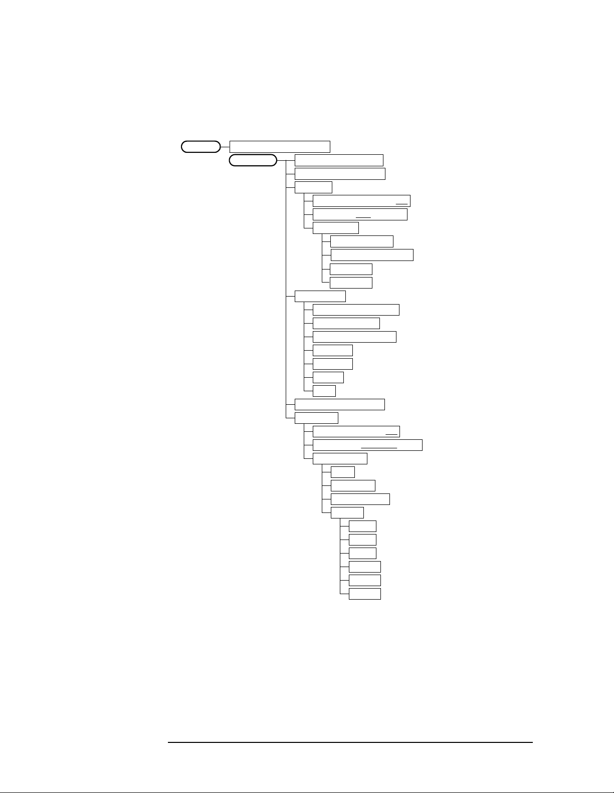
Figure 2-1 Mode Setup / Frequency Channel Key Flow (1 of 2)
cdmaOneMode
Mode Setup
Radio
Band
IS-95A
J-STD-008
Device Base | Mobile
Input
Input Port
RF
I/Q
I only
50 MHz Ref
IF Align
RF Input Range Auto|Man
Max Total Pwr -15.00 dBm
Input Atten 0.00 dB
Ext Atten
Mobile 0.00 dB
Base 0.00 dB
IF Align Signal
Signal Rate 0 =468.75kHz
Signal Amptd DAC 500
Signal Type CW, Comb, Pulse
Trigger
RF Burst
Delay 0.000 s
Peak Level -6.00 dB
Slope Pos|Neg
Video (IF Envlp)
Delay 0.000 s
Level -6.00 dBm
Slope Pos|Neg
Ext Front
Delay 0.000 s
Level 2.00 V
Slope Pos|Neg
Ext Rear
Delay 0.000 s
Level 2.00 V
Slope Pos|Neg
Trig Holdoff 0.000 s
Auto Trig 100.0 ms On|Off
Frame Timer
Period 250.0000 us
Offset 0.000 s
Reset Offset Display
Sync Source
Off
RF Burst (Wideband)
Ext Front
Ext Rear
(a)
<Auto not for Spectrum>
Chapter 2 19

Setting Up the cdmaOne Mode
cdmaOne Measurement Key Flow
Figure 2-2 Mode Setup / Frequency Channel Key Flow (2 of 2)
(a)
Demod
Sync Type
Even Sec
Pilot Sec
Ext Front
Ext Rear
None
PN Offset 0 X 64[chips]
RF Carrier Single | Multi
Frequency Channel
Center Freq 1.00000 GHz
PN Offset 0 X 64 [Chips]
20 Chapter2

Figure 2-3 Channel Power Measurement Key Flow
Setting Up the cdmaOne Mode
cdmaOne Measurement Key Flow
Measure
Channel Power
Meas Setup
Channel PowerMeasure
Amplitude Y Scale
Avg Number 20 On | Off
Avg Mode Exp | Repeat
Integ BW 1.23000 MHz
Chan Power Span 2.00000 MHz
Restore Meas Defaults
Advanced
Sweep Time 68.27 usAuto | Man
Data Points 512 Auto | Man
Trig Source
Free Run (Immediate)
Video (IF Envlp)
RF Burst (Wideband)
Ext Front
Ext Rear
Scale/Div 10.00 dB
Ref Value
Ref Position Top | Ctr | Bot
Scale CouplingOn | Off
Chapter 2 21

Setting Up the cdmaOne Mode
cdmaOne Measurement Key Flow
Figure 2-4 Modulation Accuracy (Rho) Measurement Key Flow
Measure
Mod Accuracy (Rho)
Meas Setup
Mod Accuracy (Rho)Measure
View/Trace
Avg Frames 10 On|Off
Avg Mode Exp|Repeat
Meas Intvl 1.250 ms
Spectrum Normal|Invert
Demod
Sync Type
Even Sec (Rear Trig In)
Pilot Seq
Ext Front
Ext Rear
None
PN Offset 0 X 64 [Chips]
RF Carrier Single | Multiple
Restore Meas Defaults
I/Q Measured
Compl Vector
Compl Constln
Polar Vector
Polar Constln
Measure
I/Q Error (Quad View)
Mod Accuracy (Rho)
Display
I/Q Points
Points / Chip
Chip Dots On | Off
Span X Scale
Scale/Div 1.225 chip
Ref Value 0.000 chip
Ref Position Left |Ctr|Right
Scale CouplingOn|Off
Amplitude Y Scale
Scale/Div
Ref Value
Ref Position Top |Ctr | Bot
Scale Coupling On | Off
22 Chapter2

Figure 2-5 Code Domain Measurement Key Flow
Setting Up the cdmaOne Mode
cdmaOne Measurement Key Flow
Measure
Code Domain
Meas Setup
Code DomainMeasure
View/Trace
Avg Frames 10 On | Off
Avg Mode Exp|Repeat
Meas Intvl 1.250 ms
Meas Method
Power
Timing Phase
Active Set Th -20.00 dB
Spectrum Normal | Invert
Demod
Sync Type
Even Sec (Rear Trig In)
Pilot Seq
Ext Front
Ext Rear
None
PN Offset 0 X 64 [chips]
RF Carrier Single | Multi
Restore Meas Defaults
Power Graph & Metrics
Power Graph & Markers
Power Timing & Phase
<Not available using Power Meas Method>
Measure
Code Domain
Display
Code DomainMeasure
Marker
Points / Chip 2 | 4 | 8
Select 1 | 2 | 3 | 4
Normal
Delta
Function
Band Power
Noise
Off
Trace
Power
Timing
Phase
Off
Shape
Diamond
Line
Square
Cross
Marker All Off
Chapter 2 23

Setting Up the cdmaOne Mode
cdmaOne Measurement Key Flow
Figure 2-6 Spur Close Measurement Key Flow
Measure
Spur Close
Meas Setup
Spur CloseMeasure
View/Trace
Spur CloseMeasure
Marker
Avg Number 15 On | Off
Avg Mode Exp| Repeat
Meas Type Examine |Full
Restore Meas Defaults
Lower Segment
Center Segment
Upper Segment
Select 1 | 2 | 3 | 4
Normal
Delta
Function
Band Power
Noise
Off
Trace
Spectrum
Upper Limit
Off
Shape
Diamond
Line
Square
Cross
Marker All Off
24 Chapter2

Setting Up the cdmaOne Mode
cdmaOne Measurement Key Flow
Figure 2-7 Spectrum (Freq Domain) Measurement Key Flow (1 of 3)
Measure
Spectrum (Freq Domain)
Meas Setup
Span 1.00000 MHz
Res BW 20.0000 kHz Auto|Man
Average
Trig Source
Restore Meas Defaults
Advanced
Avg Number 25 On | Off
Avg Mode Exp | Repeat
Avg Type
Pwr Avg (RMS)
Log-Pwr Avg (Video)
Voltage Avg
Maximum
Minimum
Free Run (Immediate)
Video (IF Envlp)
RF Burst (Wideband)
Ext Front
Ext Rear
Frame
Line
Pre-ADC BPF On | Off
Pre-FFT Fltr Gaussian | Flat
Pre-FFT BW 1.55000 MHz Auto | Man
FFT Window
Flat Top (High Amptd Acc)
Uniform
Hanning
Hamming
Gaussian (Alpha 3.5)
Blackman
Blackman-Harris
K-B 70 dB (Kaiser-Bessel)
K-B 90 dB (Kaiser-Bessel)
K-B 110 dB (Kaiser-Bessel)
FFT Size
Length Ctrl Auto | Man
Min Pnts/RBW 1.300000
Window Length 706
FFT Length 4096
<Not available in "Man">
<Not available in "Auto">
<Not available in "Auto">
(a)
Chapter 2 25

Setting Up the cdmaOne Mode
cdmaOne Measurement Key Flow
Figure 2-8 Spectrum (Freq Domain) Measurement Key Flow (2 of 3)
(a)
ADC Range
Auto
Auto Peak
AutoPeakLock
Manual
-6 dB
0 dB
+6 dB
+12 dB
+18 dB
+24 dB
Spectrum (Freq Domain)Measure
View/Trace
Spectrum
Span X Scale
Span 1.00000 MHz
Amplitude Y Scale
Scale/Div 10.00 dB
Ref Value 0.00 dBm
Ref Position Top | Ctr | Bot
Scale CouplingOn | Off
I/Q Waveform
Span X Scale
Scale/Div 18.8 us
Ref Value 0.00 s
Ref Position Left | Ctr | Right
Scale CouplingOn | Off
Amplitude Y Scale
Scale/Div 60.0 mV
Ref Value 0.00 V
Ref Position Top |Ctr | Bot
Scale Coupling On |Off
Trace Display
All
Average (or Max & Min)
Current
26 Chapter2

Setting Up the cdmaOne Mode
cdmaOne Measurement Key Flow
Figure 2-9 Spectrum (Freq Domain) Measurement Key Flow (3 of 3)
Spectrum (Freq Domain)Measure
Marker
Select 1|2|3|4
Normal
Delta
Function
Band Power
Noise
Off
Trace
Spectrum
Spectrum Avg
I/Q Waveform
Off
Shape
Diamond
Line
Square
Cross
Marker All Off
Chapter 2 27
Setting Up the cdmaOne Mode
cdmaOne Measurement Key Flow
Figure 2-10 Waveform (Time Domain) Measurement Key Flow (1 of 2)
Measure
Waveform (Time Domain)
Meas Setup
Sweep Time 2.000 ms
Res BW 2.00000 MHz
Average
Avg Number 10 On | Off
Avg Mode Exp | Repeat
Trig Source
Free Run (Immediate)
RF Burst (Wideband)
Ext Front
Frame
Line
Restore Meas Defaults
Advanced
Pre-ADC BPF On | Off
Avg Type
Pwr Avg (RMS)
Log-Pwr Avg (Video)
Maximum
Minimum
Video (IF Envlp)
Ext Rear
RBW Filter Gaussian | Flat
ADC Range
Auto
Auto Peak
AutoPeakLock
Manual
-6 dB
0 dB
+6 dB
+12 dB
+18 dB
+24 dB
28 Chapter2

Setting Up the cdmaOne Mode
cdmaOne Measurement Key Flow
Figure 2-11 Waveform (Time Domain) Measurement Key Flow (2 of 2)
Waveform (Time Domain)Measure
View/Trace
Waveform (Time Domain)Measure
Marker
RF Envelope
Span X Scale
Scale/Div 200.0 us
Ref Value 0.00 s
Ref Position Left | Ctr | Right
Scale CouplingOn | Off
Amplitude Y Scale
Scale/Div 10.00 dB
Ref Value 0.00 dBm
Ref Position Top | Ctr| Bot
Scale CouplingOn | Off
I/Q Waveform
Span X Scale
Scale/Div 200.0 us
Ref Value 0.00 s
Ref Position Left | Ctr | Right
Scale CouplingOn | Off
Amplitude Y Scale
Scale/Div 100.0 mV
Ref Value 0.00 V
Ref Position Top |Ctr | Bot
Scale CouplingOn | Off
Select 1|2|3|4
Normal
Delta
Function
Band Power
Noise
Off
Trace
RF Envelope
I/Q Waveform
Off
Shape
Diamond
Line
Square
Cross
Marker All Off
Chapter 2 29

Setting Up the cdmaOne Mode
cdmaOne Measurement Key Flow
Figure 2-12 ACPR Measurement Key Flow
Measure
Measure
ACPR
Meas Setup
ACPR
View/Trace
Avg Number 20 On|Off
Avg Mode Exp |Repeat
Chan Integ BW 1.23000 MHz
Meas Type
Total Pwr Ref
PSD Ref
Ofs & Limits
Offset A, B, C, D, E
Offset Freq 750.000 kHz On|Off
Ref BW 30.000 kHz
Abs Limit 0.00 dBm
Fail
AND
OR
Absolute
Relative
Rel Lim (Car)
Rel Lim (PSD)
Bar Graph
Spectrum
<default selection: A>
30 Chapter2

Setting Up the cdmaOne Mode
Installing Optional Measurement Personalities
Installing Optional
Measurement Personalities
Installing a measurement personality is a two step process.
1. The measurement personality firmware must be installed into the
instrument.
2. A license key number must be entered which enables the
measurement personality to run. (Refer to the “License Key
Numbers” section.)
Adding additional measurement personalities requires purchasing a
retrofit kit for the desired option. The retrofit kit includes the
measurement personality firmware, usually supplied on a zip disk. The
license key certificate, included in the kit, contains the license key
number. Every retrofit kit will have installation instructions.
The installation instructions require you to know three pieces of
information about your instrument; the amount of memory installed,
the Host ID, and the instrument serial number.
To find: Key Path:
Instrument
Memory:
__________________
Host ID:
__________________
Instrument
Serial Number:
__________________
Exit Main Firmware key. This key is only for use when you want to update
System, File System
(the amount of memory in your
instrument will be the sum of the
memory and the Free memory)
System, Show System, Host ID
System, Show System, Serial Number
Used
firmware using a LAN connection. The Exit Main Firmware key halts
the operation of the resident firmware code so you can install an
updated version of firmware using a LAN connection. Instructions for
loading future firmware updates are available at the following URL:
www.agilent.com/find/vsa/
Chapter 2 31

Setting Up the cdmaOne Mode
Installing Optional Measurement Personalities
Available Options
The option designation consists of three characters, as shown in the
Option column of the table below.
Available Personality Options
GSM measurement personality BAH
cdmaOne measurement personality BAC
NADC, PDC measurement personalities BAE
iDEN measurement personality HN1
W-CDMA measurement personality BAF
cdma2000 measurement personality B78
a
Option
a. As of the print date of this measurement guide.
License Key Numbers
The measurement personality you have purchased with your
instrument has been installed and enabled at the factory. With the
purchase of the measurement personality, and with any future
purchase of a new personality, you will receive a unique license key
number. The license key number is a hexadecimal number that is for
your specific measurement personality and instrument serial number.
The license key enables you to install, or reactivate any personality you
have purchased.
Follow these steps to locate the unique license key number for the
measurement personality that has come installed in your instrument:
1. Press
System, More (1 of 3), More (2 of 3), Install, Choose Option. When
you press the Choose Option key the alpha editor will be activated.
Use the alpha editor to enter the letters (upper-case) and the
front-panel numeric keyboard to enter the numbers (if required) for
the personality option that has been installed in the instrument.
2. Press the
number for your instrument will now appear on the
Done key on the alpha editor menu. The unique license key
License Key
softkey.
32 Chapter2

Setting Up the cdmaOne Mode
Installing Optional Measurement Personalities
You will want to keep a copy of your license key number in a
secure location. Please enter your license key numbers in the
box provided below for future reference. If you should lose your
license key number, call your nearest Agilent Technologies
service or sales office for assistance.
License Key Numbers for Instrument with Serial # ________
For Option______________ the license key number is _____________________
For Option______________ the license key number is _____________________
For Option______________ the license key number is _____________________
For Option______________ the license key number is _____________________
For Option______________ the license key number is _____________________
For Option______________ the license key number is _____________________
If you purchase an option later, you will receive a certificate which
displays the unique license key number that you will need to install
that option.
NOTE You will need to use a license key number only if you purchase an
additional measurement personality, or if you want to reactivate a
measurement personality that has been deactivated.
Installing a License Key Number
NOTE Follow this procedure to reinstall a license key number which has been
deleted during the uninstall process, or lost due to a memory failure.
Toinstall a license key number for the selected option, use the following
procedure:
1. Press
Pressing the
Use the alpha editor to enter the letters (upper-case) and the
front-panel numeric keyboard to enter the numbers (if required) for
the option designation, then press the
option, you will see your entry in the active function area of the
display.
2. Press License Key. Entering the license key number will require
entry of both letters and numbers. Use the alpha editor to enter
letters. Use the front-panel numeric keyboard to enter numbers. You
will see your entry in the active function area of the display. When
you have completed entering the license key number, press the
key.
System, More(1 of 3), More(2 of 3), Install, Choose Option.
Choose Option key will activate the alpha editor menu.
Done key. As you enter the
Done
Chapter 2 33

Setting Up the cdmaOne Mode
Installing Optional Measurement Personalities
3. Press the Install Now key after you have entered the active license
key number and the personality option. When pressed, a message
may appearinthefunctionareaofthe display which reads, “Insert
disk and power cycle the instrument”. Disregard this
message. Press the
No key only if you wish to cancel the installation
process. If you want to proceed with the installation, press the
key and cycle the instrument power off and then on.
Using the Uninstall Key
The following procedure removes the license key number for the
selected option. This will make the option unavailable for use, and the
message “Application Not Licensed” will appear in the Status/Info
bar at the bottom of the display. Please write down the 12-digit license
key number for the option before proceeding. If that measurement
personality is to be used at a later date you will need the license key
number to reactivate the personality firmware.
NOTE Using the Uninstall key does not remove the personality from the
instrument memory, and does not free memory to be available to install
another option. If you need to free memory to install another option,
refer to the instructions for loading firmware updates located at the
URL: www.agilent.com/find/vsa/
Yes
1. Press
Pressing the
System, More(1 of 3), More(2 of 3), Uninstall, Choose Option.
Choose Option key will activate the alpha editor menu.
Use the alpha editor to enter the letters (upper-case) and the
front-panel numeric keyboard to enter the numbers (if required) for
the option, then press the
Done key. As you enter the option, you will
see your entry in the active function area of the display.
2. Press the Uninstall Now key after you have entered the personality
option. Press the
process. Press the
No key only if you wish to cancel the uninstall
Yes key if you want to continue the uninstall
process.
3. Cycle the instrument power off and then on to complete the uninstall
process.
34 Chapter2

3 Making cdmaOne Measurements
35

Making cdmaOne Measurements
cdmaOne Measurements
cdmaOne Measurements
Once in the cdmaOne mode, the following measurements are available
by pressing the
❏ Channel Power on page 40
❏ Modulation Accuracy (Rho) on page 45
❏ Code Domain on page 51
❏ Spur Close on page 56
❏ Spectrum (Frequency Domain) on page 62
❏ Waveform (Time Domain) on page 70
❏ ACPR (Adjacent Channel Power Ratio) on page 77
These are referred to as one-button measurements. When you press the
key to select the measurement it will become the active measurement,
using settings and a display unique to that measurement. Data
acquisitions will automatically begin provided trigger requirements, if
any, are met.
Measure key:
36 Chapter3

Making cdmaOne Measurements
Preparing for Measurements
Preparing for Measurements
If you want to set the cdmaOne mode to a known, factory default state,
press
Preset. This will preset the mode setup and all of the
measurements to the factory default parameters. Note that
not switch modes.
To preset only the settings that are specific to the selected
measurement, press
Meas Setup, More, Restore Meas Defaults. This will
set the measurement setup parameters, for the currently selected
measurement only, to the factory defaults.
Initial Setup
Before making a measurement, make sure the mode setup and
frequency channel parameters are set to the desired settings. Refer to
the sections “Changing the Mode Setup” and “Changing the Frequency
Channel” in the previous chapter.
Preset does
How to Make a Measurement
Follow the three-step process shown in the table below:
Step Primary Key Setup Keys Related Keys
1. Select &
setup a mode
2. Select &
setup a measurement
3. Select &
setup view
Measure Control
The Meas Control front panel menu key controls processes that affect
the running of the current measurement.
•
Mode Mode Setup, Input,
Frequency Channel
Measure Meas Setup Meas Control,
View/Trace Span X Scale,
Amplitude Y Scale
Next Window, Zoom
Measure key. Press Meas Control, Measure (not to be confused with the
front panel
Measure key which has a different function) to toggle
, Display,
System
Restart
File
, Save,
Print, Print Setup,
Marker, Search
between Single and Cont (for continuous) measurement states.
When set to Single, the measurement will continue until it has
reached the specified number of averages set by the average counter.
When set to Cont, the measurement will run continuously, and
perform averaging according to the current average type (repeat or
exponential). The default setting is continuous.
•
Pause key. Press Meas Control, Pause to pause the current
Chapter 3 37

Making cdmaOne Measurements
Preparing for Measurements
measurement. Once toggled, the label of the Pause key changes to
read
Resume; the Resume key, once pressed, continues the active
measurement from the point at which it was paused.
• Restart key. Press Restart front panel key to repeat the current
measurement from the beginning, while retaining the current
measurement settings.
Measurement Setup
The Meas Setup key accesses features that enable you to adjust
parameters of the current measurement, such as resolution bandwidth.
You will also use the
and
Advanced measure setup feature menus.
The following measure setup features can be used with many or all
measurements:
Res BW key. Press Meas Setup, Res BW to change the resolution of a
•
given measurement. Selection of a narrower bandwidth will result in
a longer data acquisition time.
Meas Setup menu to access Average, Trig Source,
•
Restore Meas Defaults key. Press Meas Setup, More, Restore Meas
Defaults to preset only the settings that are specific to the selected
measurement. This will set the measure setup parameters, for the
currently selected measurement only, to the factory defaults.
Averaging
Selecting one of the averaging keys in the
Meas Setup menu will allow
you to modify the number, average mode, and type of averaging you use
for the currently selected measurement.
•
Avg Number - will allow you to change the number of N averages to
be made.
• Avg Mode - will allow you to choose either exponential or repeat
averaging.Thisselection only effects the averaging after the number
of N averages is reached (set using
Avg Number).
— Normal averaging: Normal (linear) averaging is always used
until the specified number of N averages is reached. When
Measure is set at Single, data acquisitions are stopped when the
number of averages is reached - thus
Avg Mode has no effect on
single measurements.
— Exponential averaging: When Measure is set at Cont, data
acquisitions will continue indefinitely. After N averages,
exponential averaging is used with a weighting factor of N (the
displayed average count stops at N). Exponential averaging
weights new data more than old data, which allows tracking of
slow-changing signals. The weighting factor N is set using
Avg Number.
38 Chapter3

Making cdmaOne Measurements
Preparing for Measurements
— Repeat averaging: When Measure is set at Cont, data
acquisitions will continue indefinitely. After N averages is
reached, all previous result data is cleared and the average count
is set back to 1. This is equivalent to being in
pressing the
Restart key each time the single measurement
Measure Single and
finishes.
Trigger Source
Changing the
Trig Source alters the trigger source for the selected
measurement only. Not all of the selections are available for all
measurements. Many CDMA measurements do not require a trigger.
These do not have a Trig Source key. Note that the
Envlp), Ext Front, and Ext Rear menu keys found in the Trigger menu
RF Burst, Video (IF
enable you to change settings to modify the delay, level, and slope for
each of these trigger sources. Choose one of the following trigger
sources:
•
Free Run (Immediate) - the trigger occurs at the time the data is
requested, completely asynchronous to the RF or IF signal.
• Video (IF Envlp) - an internal IF envelope trigger. It triggers on an
absolute threshold level of the signal passed by the IF.
• RF Burst (Wideband) - an internal wideband RF burst trigger that has
an automatic level control for burst signals. It triggers on a level
that is relative to the peak of the signal passed by the RF (12 MHz
bandwidth).
•
Ext Front - activates the front panel EXT TRIGGER INPUT. The
external trigger must be a signal between −5 and +5 volts.
• Ext Rear - activates the rear panel TRIGGER IN. The external trigger
must be a signal between −5 and +5 volts.
• Trig Holdoff - sets the minimum time after a trigger, before a
re-trigger can occur.
• Frame - uses the internal frame clock to generate a trigger signal.
The clock parameters are controlled under the
Mode Setup key or the
measurement firmware, not both. See the specific measurement for
details.
•
Line - activates an internal line trigger. Sweep triggers occur at
intervals synchronized to the line frequency.
Rear panel TRIGGER 1 OUT and TRIGGER 2 OUT connectors are coupled
to the selected trigger source. These trigger outputs are always on the
rising edge with a pulse width of at least 1 µs.
Chapter 3 39

Making cdmaOne Measurements
Making the Channel Power Measurement
Making the Channel Power Measurement
Purpose
The Channel Powermeasurementis a common test used in the wireless
industry to measure the total transmitted power of a radio within a
defined frequency channel. This procedure measures the total power
within the defined channel. This measurement is applied to design,
characterize, evaluate, and verify transmitters and its components or
devices for base stations and mobile stations.
Measurement Method
The Channel Power measurement reports the total power within the
channel bandwidth. The transmitter tester acquires a number of points
representing the input signal in the time domain. It transforms this
information into the frequency domain using FFT and then calculates
the channel power. The effective resolution bandwidth of the frequency
domain trace is proportional to the number of points acquired for FFT.
The fastest FFT process is achieved using a number of acquired points
that is a power of 2 (for example: 64, 128, 512). Since the measurement
is optimized for speed and accuracy, you are permitted to change only
the number of acquired data points in powers of 2, not the actual
resolution bandwidth. However, if absolute sweep time is required,
sweep time can be changed to the user’s specified time at the expense of
reduced speed. At no time will both sweep time and data points be set
to manual because of conflicting parameter settings. This flexibility is
available through the
measurement.
Advanced menu of the channel power
To improve repeatability, you can increase either the number of
averages or the number of data points with longer time record length.
The channel power graph is shown in the graph window and the
absolute channel power in dBm and the mean power spectral density in
dBm/Hz are shown in the text window.
Making the Measurement
NOTE The factory default settings provide a good starting point. You will
likely want to change some of the settings. Press
2), Restore Meas Defaults at any time to return all parameters for the
current measurement to their default settings.
Select the desired center frequency.
Press
the active measurement.
40 Chapter3
Measure, Channel Power to immediately make Channel Power
Meas Setup, More (1 of

Tochange any of the measurement parameters from the factory default
values, refer to the “Changing the Measurement Setup” section.
Results
The following figure shows an example result of channel power
measurements. The channel power graph is shown in the graph
window. The absolute channel power and its mean power spectral
density are shown in the text window.
Figure 3-1 Channel Power Measurement
Making cdmaOne Measurements
Making the Channel Power Measurement
Chapter 3 41

Making cdmaOne Measurements
Making the Channel Power Measurement
Changing the Measurement Setup
The next table shows the factory default settings for channel power
measurements.
Table 3-1 Channel Power Measurement Defaults
Measurement Parameter Factory Default Condition
Meas Setup:
Avg Number 20 On
Avg Mode Repeat
Integ BW 1.23000 MHz
Chan Power Span 2.00000 MHz
Advanced
Sweep Time 68.27 µs Auto
Data Points 512 Auto
Trig Source Free Run (Immediate)
NOTE Parameters under the Advanced key seldom need to be changed. Any
changes from the factory default values may result in invalid
measurement data.
Make sure the
Measure menu. The Meas Setup key accesses the menu which allows you
Channel Power measurement is selected under the
to modify the average number and average mode for this measurement.
The following parameters can be changed according to your
measurement requirement:
• Integ BW - Allows you to specify the integration bandwidth in
which the power is measured. The range is 1.000 kHz to 10.0000
MHz with 1 or 10 Hz resolution.
• Chan Pwr Span - Allows you to set the frequency span for the
channel power measurement. The range is 1.626 to 10 times the
integration bandwidth but limited up to 10 MHz with 1 or 10 Hz
resolution. This span is used for the current
Chan Pwr Span is coupled to Integ BW, if you change the integration
Integ BW setting. Since
bandwidth setting, the channel power span setting changes by a
proportional amount until a limit value is reached.
42 Chapter3

Making cdmaOne Measurements
Making the Channel Power Measurement
In addition, the following parameters for channel power measurements
can be modified by pressing the
Sweep Time - Allows you to manually change the sweep time and also
•
to toggle the sweep time control between
Advanced key:
Auto and Man (manual).
The range is 1.000 µs to 50.00 ms with 1 or 10 µs resolution. The
default setting is 68.27 µs and
Auto.
• Data Points - Allows you to select the number of data points. The
automatic mode chooses the optimum number of points for the
fastest measurement time with acceptable repeatability. The
minimum number of points that could be used is determined by the
sweep time and the sampling rate. You can increase the length of the
measured time record (capture more of the burst) by increasing the
number of points, but the measurement will take longer.
•
Res BW - Shows information on the resolution bandwidth derived
from the sweep time.
• Trig Source - Allows you to choose the trigger source from Free Run
(Immediate), Video (IF Envl), RF Burst (Wideband), Ext Front or Ext Rear.
Changing the Display
The Amplitude Y Scale key accesses the menu to set the desired vertical
scale and associated settings.
•
Scale/Div - Allows you to enter a numeric value to change the vertical
display sensitivity. The range is 0.10 to 20.00 dB with 0.01 dB
resolution. The default setting is 10.00 dB, however, since
Coupling is defaulted to On, this value is automatically determined
by the measurement result.
• Ref Value - Allows you to enter a numeric value to change the
absolute power value as the display reference. The range is 0.00 to
250.00 dBm with 0.01 dB resolution, however, since
defaulted to
On, this value is automatically determined by the
Scale Coupling is
measurement result.
• Ref Position - Allows you to set the display reference position to
either
Scale Coupling - Allows you to toggle the scale coupling function
•
between
Top, Ctr (center), or Bot (bottom). The default setting is Top.
On and Off. The default setting is On. This function
automatically determines the scale per division and reference values
by the measurement results.
Scale
Chapter 3 43

Making cdmaOne Measurements
Making the Channel Power Measurement
Troubleshooting Hints
If an external attenuator is used, be sure to include its attenuation in
the measurement of the channel power. Use the Ext Atten key.
The channel power measurement, very often along with the adjacent
channel power ratio measurement and/or spectrum measurement, can
reveal degraded or defective parts in the transmitter section of the
UUT. The following examples are those areas to be checked further.
• Some faults in the DC power supply control of the transmitter power
amplifier, RF power controller of the pre-power amplifier stage,
and/or I/Q control of the baseband stage.
• Some degradation in the gain and output power level of the amplifier
due to the degraded gain control and/or increased distortion.
• Some degradation of the amplifier linearity and other performance
characteristics.
44 Chapter3

Making cdmaOne Measurements
Making the Modulation Accuracy (Rho) Measurement
Making the Modulation Accuracy (Rho)
Measurement
Purpose
This procedure measures the performance of the transmitter’s
modulation circuitry.
Measurement Method
The E4406A can perform base station and mobile measurements. In
both cases the transmitter’s modulated signal is compared to an ideal
reference waveform. Rho values are in the range of 0 to 1. A value of 1
indicates perfect correlation to the reference (high modulation quality).
The cdmaOne base station standards require that transmitters have a
Rho performance of 0.912 or greater.
When performing mobile testing with the Rho measurement, the phone
must be placed in a test mode to modulate only the known short code
sequences in the reverse link. The measurement will not work with a
live phone call on which data is being modulated.
With the Rho measurement, the following data is provided:
• Rho - modulation quality
• Time Offset - how well your transmitter’s signal is time-aligned to
system time
• Frequency Error - the frequency difference between your
transmitter’s actual center frequency and the frequency (or channel)
that you entered
• Carrier Feedthrough - measures the performance of the I/Q
modulator of your transmitter
• EVM - rms Error Vector Magnitude
• Mag Error - rms Magnitude Error
• Phase Error - rms Phase Error
Chapter 3 45

Making cdmaOne Measurements
Making the Modulation Accuracy (Rho) Measurement
Making the Measurement
NOTE The factory default settings provide a cdmaOne compliant
measurement. For special requirements, you may need to change some
of the settings. Press
any time to return all parameters for the current measurement to their
default settings.
Select the desired center frequency and PN offset as described under
“Changing the Frequency Channel” on page 17.
Meas Setup, More (1 of 2), Restore Meas Defaults at
Press
Measure, Mod Accuracy (Rho) to immediately make Modulation
Accuracy the active measurement.
Tochange any of the measurement parameters from the factory default
values, refer to “Changing the Measurement Setup” on page 49.
46 Chapter3

Making cdmaOne Measurements
Making the Modulation Accuracy (Rho) Measurement
Results
Figure 3-2 Modulation Accuracy Result - Quad View (chip dots off)
Figure 3-3 Modulation Accuracy Result - Phase Error View
Chapter 3 47

Making cdmaOne Measurements
Making the Modulation Accuracy (Rho) Measurement
Figure 3-4 Modulation Accuracy Result - EVM View
Figure 3-5 Modulation Accuracy Result - Polar Vector View
48 Chapter3

Making cdmaOne Measurements
Making the Modulation Accuracy (Rho) Measurement
Changing the Measurement Setup
Table 3-2 Modulation Accuracy (Rho) Measurement Defaults
Measurement Parameter Factory Default Condition
Avg Frames 10 On
Avg Mode Repeat
Meas Intvl 1.25 ms
Spectrum Normal
Demod
Sync Type
PN Offset
RF Carrier
Even Sec (Ext Rear)
0 × 64[chips]
Single
Make sure the Mod Accuracy (Rho) measurement is selected under the
Measure menu. Press the Meas Setup key to access a menu which allows
you to modify the averaging, measurement interval, spectrum, and
demodulation (as described in the “Measurement Setup” on page 38).
•
Meas Interval - Sets the time interval over which the measurement is
made.
• Spectrum - This key, when set to Invert, conjugates the spectrum,
which equivalently negates the quadrature component in
demodulation. The correct setting (
Normal or Invert) depends on
whether the signal being given to the transmitter tester has a high
or low side mix.
Chapter 3 49

Making cdmaOne Measurements
Making the Modulation Accuracy (Rho) Measurement
Changing the View
The View/Trace key will allow you to select the desired view of the
measurement from the following:
•
I/Q Error (Quad-View) - See Figure 3-2 on page 47. Provides a
combination view including:
Window 1: Magnitude Error vs. chip
Window 2: Phase Error vs. chip
Window 3: EVM vs. chip
Window 4: Numeric results
Any of these windows can be selected (using the
and made full size (using the
I/Q Measured- Provides a combination view of numeric results and a
•
Zoom key).
Next Window key)
polar graph.
Window 1: Numeric Results
Window 2: Polar Graph
Four different graphic views can be chosen:
— Complimentary Vector
— Complimentary Constellation
— Polar Vector
— Polar Constellation
Changing the Display
The Display key will allow you to access the following keys:
• I/Q Points - Default is 750.
• Points/Chip - Default is 4. This is the number of sample points
displayed per chip.
• Chip Dots - Default is On. Set to Off if you do not want the chip dots
to be superimposed on the Result traces.
50 Chapter3

Making cdmaOne Measurements
Making the Code Domain Measurement (Base Station Only)
Making the Code Domain Measurement
(Base Station Only)
Purpose
The code domain measurement displays the power for each of the 64
Walsh channels, relative to the total power inside a 1.23 MHz
bandwidth centered at the Center Frequency. Each Walsh channel level
is displayed as an individual vertical bar. Because this is a relative
measurement, the unit of measure is dB (not dBm or watts). This
allows a comparison of signal levels between the Pilot, Sync, Paging,
and Traffic channels.
Measurement Method
This procedure measures the power, timing, and phase of the 64 Walsh
channels in a single RF channel. The measurement method can be
selected to either measure just code domain power, or to measure code
domain power, timing, and phase. The measurement runs faster when
measuring only code domain power.
Code Domain Phase
Code Domain Phase displays the phase error for each of the 64 Walsh
channels relative to thePilotchannel.Displaysabove the zero reference
in the center of the screen indicate that the Walsh channel leads the
Pilot channel; displays below the zero reference in the center of the
screen indicate that the Walsh channel lags the Pilot channel. Move the
marker (if we have markers!) to read the phase for each individual
channel.
Code Domain Timing
Code Domain Timing displays the time offset for each of the 64 Walsh
channels relative to the Pilot channel which is Walsh code zero.
Displays above the reference indicate that the Walsh channel leads the
Pilot channel; displays below the zero reference indicate that the Walsh
channel lags the Pilot channel. Move the marker to read the Timing for
each individual channel
Time Offset
Time Offset indicates how well your transmitter’s signal is time-aligned
to system time. The displayed value takes into account the PN
Sequence Offset Index of your transmitter that is entered using the
Offset key
PN
Chapter 3 51

Making cdmaOne Measurements
Making the Code Domain Measurement (Base Station Only)
Frequency Error
Frequency Error is the frequency difference between your transmitter’s
actual center frequency and the frequency (or channel) that you
entered.
Carrier Feedthrough
Carrier Feedthrough is used to measure the performance of the I/Q
modulator of your transmitter. Extremely low values indicate a very
good I/Q modulator.Higher values indicate potential problems with the
I/Q modulator. If Carrier Feedthrough measures higher than
approximately −20 dBc, there may be problems with the base station.
Avg AT Average Active Traffic Power (of all active Walsh
channels). A Walsh channel is considered active if its
power is above the value set by the
Max IT Maximum Inactive Traffic power (of all inactive Walsh
Active Set Th key.
channels).
Avg IT Average Inactive Traffic power (of any inactive Walsh
channel).
Making the Measurement
NOTE The factory default settings provide a cdmaOne compliant
measurement. For special requirements, you may need to change some
of the settings. Press
any time to return all parameters for the current measurement to their
default settings.
Select the desired center frequency and PN offset as described under
“Changing the Frequency Channel” on page 17.
Press
Measure, Code Domain to immediately make Code Domain Power
the active measurement.
Tochange any of the measurement parameters from the factory default
values, refer to “Changing the Measurement Setup” on page 54.
Meas Setup, More (1 of 2), Restore Meas Defaults at
52 Chapter3

Making cdmaOne Measurements
Making the Code Domain Measurement (Base Station Only)
Results
Figure 3-6 Code Domain Measurement - Power Graph and Metrics View
Figure 3-7 Code Domain Measurement - Power Graph and Markers View
Chapter 3 53

Making cdmaOne Measurements
Making the Code Domain Measurement (Base Station Only)
Figure 3-8 Code Domain Measurement - Power, Timing, and Phase View
Changing the Measurement Setup
Table 3-3 Code Domain Measurement Defaults
Measurement Parameter Factory Default Condition
Avg Frames 10 On
Avg Mode Repeat
Meas Interval 1.250 ms
Meas Method Power
Active Set Th −20.00 dB
Spectrum Normal
Demod
Sync Type
PN Offset
RF Carrier
Even Sec (Ext Rear)
0 × 64[chips]
Single
54 Chapter3

Making cdmaOne Measurements
Making the Code Domain Measurement (Base Station Only)
Make sure the Code Domain measurement is selected under the Measure
menu. Press the Meas Setup key to access a menu which allows you to
modify the measurement parameters.
Meas Invl Sets the time interval over which the measurement is
made.
Meas Method — Power - Only measures code domain power (fastest).
Timing Phase - Measures code domain power, timing,
—
and phase.
Active Set Th Active Set Threshold sets the relative power level used
to separate active from inactive traffic channels.
Changing the View
The View/Trace key will allow you to select the desired view of the
measurement from the following. Each of these views contains multiple
windows that can be selected (using the
size (using the
Zoom key).
Next Window key)and made full
Power Graph & Metrics Provides a combination view including:
• Window 1: Code Domain Power
• Window 2: Numeric Summary
Power Graph & Markers Provides a combination view including:
• Window 1: Code Domain Power
• Window 2: Numeric results for any 4 code channels
(user set by using Markers)
Power Timing & Phase Provides a combination view including:
• Window 1: Code Domain Power
• Window 2: Code Domain Timing
• Window 3: Code Domain Phase
Changing the Display
The Display key will allow you to access the Points/Chip - Default is 2
Chapter 3 55

Making cdmaOne Measurements
Making the Spur Close Measurement
Making the Spur Close Measurement
Purpose
This procedure measures the spurious emissions in the transmit band
relative to channel power in the selected channel. The unit under test is
typically set for maximum output power. The measurement can be used
when the unit under test is set for output power less than maximum,
however the limits used might not be correct.
Measurement Method
The transmit band spectrum is measured in several frequency
segments using resolution bandwidths as specified by the standard.
The channel power (integrated power in a 1.23 MHz bandwidth) is
measured first, and then used as a reference for the measurement limit
lines. The spectrum, centered around the carrier as well as above and
below the carrier, is then measured. For each spectrum segment, the
measurement looks for the spectrum peak closest to the limit and
reports it as the Worst Spur. The amplitude difference from peak to the
limit line (∆ from Limit), the frequency difference from the peak to the
center of the channel (Offset Freq), and the amplitude difference from
the peak to the channel power (∆ from Carrier) are displayed. If the
peak goes above the limit line, the display will indicate FAIL. If
is on, the active marker is placed at the worst spur of the displayed
segment.
Marker
56 Chapter3

Making cdmaOne Measurements
Making the Spur Close Measurement
Table 3-4 Spurious Emission Limits When Transmitting
Band Device Type Frequency Offset Limit
IS-95-A Base > 750 kHz −45 dBc/30 kHz
> 1.98 MHz −60 dBc/30 kHz
outside channel’s band
but inside Tx band
outside Tx band −13 dBm/100 kHz
Mobile > 885 kHz −42 dBc/30 kHz
> 1.98 MHz −54 dBc/30 kHz
outside channel’s band
but inside Tx band
outside Tx band −13 dBm/100 kHz
J-STD-008 Base > 885 kHz −45 dBc/30 kHz
≤ 1 MHz outside &
adjacent to the channel’s band
> 1 MHz outside channel’s band
but inside Tx band
outside Tx band -13 dBm/1 MHz
Mobile > 1.265 MHz -42 dBc/30 kHz
−13 dBm/30 kHz or
−60 dBc/30 kHz, whichever is
the smaller power
-54 dBm/30 kHz
−13 dBm/12.5 kHz or
−80 dBc/12.5 kHz, whichever is
the greater power
−13 dBm/1 MHz or
−80 dBc/1 MHz, whichever is
the greater power
≤ 1 MHz outside &
adjacent to the channel’s band
> 1 MHz outside channel’s band
but inside Tx band
outside Tx band -13 dBm/1 MHz
Chapter 3 57
-13 dBm/12.5 kHz
-13 dBm/1 MHz

Making cdmaOne Measurements
Making the Spur Close Measurement
Making the Measurement
NOTE The factory default settings provide a cdmaOne compliant
measurement. For special requirements, you may need to change some
of the settings. Press
any time to return all parameters for the current measurement to their
default settings.
Select the desired center frequency as described under “Changing the
Frequency Channel” on page 17.
Meas Setup, More (1 of 2), Restore Meas Defaults at
Press
Measure, Spur Close to immediately make Spur Close the active
measurement.
Tochange any of the measurement parameters from the factory default
values, refer to “Changing the Measurement Setup” on page 61.
58 Chapter3

Making cdmaOne Measurements
Making the Spur Close Measurement
Results
Figure 3-9 Spur Close Measurement, IS-95A - Center Segment View
Figure 3-10 Spur Close Measurement, IS-95A - Lower Segment View
Chapter 3 59

Making cdmaOne Measurements
Making the Spur Close Measurement
Figure 3-11 Spur Close Measurement, IS-95A - Upper Segment View
60 Chapter3

Changing the Measurement Setup
Table 3-5 Spur Close Measurement Defaults
Measurement Parameter Factory Default Condition
Avg Number 15 On
Avg Mode Repeat
Meas Type Full
Make sure the Spur Close measurement is selected under the Measure
menu. Press the Meas Setup key to access a menu which allows you to
modify the measurement parameters.
Changing the View
The View/Trace key will allow you to select the desired view of the
measurement from the following. Each of these choices selects a
different part of the frequency spectrum for viewing. The Center
Segment shows the spectrum centered on the carrier channel frequency.
Making cdmaOne Measurements
Making the Spur Close Measurement
When
•
•
Band is set to IS-95:
Lower Segment
Center Segment
• Upper Segment
When Band is set to J-STD-008:
Lower Segment
•
•
Lower 1 MHz Adj Segment
•
Center Segment
• Upper 1 MHz Adj Segment
• Upper Segment
Chapter 3 61

Making cdmaOne Measurements
Making the Spectrum (Frequency Domain) Measurement
Making the Spectrum (Frequency Domain)
Measurement
Purpose
The spectrum measurement provides spectrum analysis capability for
the instrument. The control of the measurement was designed to be
familiar to those who are accustomed to using swept spectrum
analyzers.
This measurement is FFT (Fast Fourier Transform) based. The
FFT-specific parameters are located in the
available under basic mode spectrum measurements is an
I/Q window, which shows the I and Q signals in parameters of voltage
and time. The advantage of having an I/Q view available while in the
spectrum measurement is that it allows you to view complex
components of the same signal without changing settings or
measurements.
Advanced menu. Also
Measurement Method
The transmitter tester uses digital signal processing to sample the
input signal and convert it to the frequency domain. With the
instrument tuned to a fixed center frequency, samples are digitized at a
high rate, converted to I and Q components with DSP hardware, and
then converted to the frequency domain with FFT software.
Making the Measurement
NOTE The factory default parameters provide a good starting point.You will
likely want to change some of the settings. Press
2), Restore Meas Defaults at any time to return all parameters for the
current measurement to their default settings.
Press
Spectrum (Frequency Domain) the active measurement.
Tochange any of the measurement parameters from the factory default
values, refer to the “Changing the Measurement Setup” section for this
measurement.
Measure, Spectrum (Freq Domain) to immediately make
Meas Setup, More (1 of
62 Chapter3

Making cdmaOne Measurements
Making the Spectrum (Frequency Domain) Measurement
Results
A display with both a spectrum window and an I/Q Waveform window
will appear when you activate a spectrum measurement. Use the
Window key to select a window, and the Zoom key to enlarge a window.
Figure 3-12 Spectrum Measurement Result- Spectrum Window
Next
Chapter 3 63

Making cdmaOne Measurements
Making the Spectrum (Frequency Domain) Measurement
Changing the Measurement Setup
Table 1 Spectrum (Frequency Domain) Measurement Defaults
Measurement Parameter Factory Default Condition
Res BW 20.0000 kHz (Auto)
Averaging:
Avg Number
Avg Mode
Avg Type
Trigger Source Free Run (Immediate)
25 On
Exp
Log-Pwr Avg (Video)
Meas Time
(Service mode only)
Spectrum Window:
Span
Scale/Div - Amplitude Y Scale
I/Q Waveform Window:
Capture Time
Scale/Div - Amplitude Y Scale
Advanced
Pre-ADC BPF On
Pre-FFT Fltr Flat
Pre-FFT BW 1.55000 MHz (Auto)
FFT Window Flat Top (High AmptdAcc)
FFT Size:
Length Control
Min Pnts/RBW
Window Length
FFT Length
ADC Range Auto Peak
1.0 ms (Auto)
1.00000 MHz
10.00 dB
188.00 µs
60 mV
Auto
1.300000
706
4096
Data Packing Auto
ADC Dither Auto
Decimation 0 (Auto)
IF Flatness On
64 Chapter3

Making cdmaOne Measurements
Making the Spectrum (Frequency Domain) Measurement
NOTE Parameters under the Advanced key seldom need to be changed. Any
changes from the default advanced values may result in invalid
measurement data.
Make sure the
the
Measure menu. Press the Meas Setup key to access a menu which
Spectrum (Freq Domain) measurement is selected under
allows you to modify the averaging, and trigger source for this
measurement (as described in the “Measurement Setup” section). In
addition, the following parameters can be modified:
•
Span - This key allows you to modify the frequency span. Changing
the span causes the bandwidth to change automatically, and will
affect data acquisition time.
•
Res BW - This feature sets the resolution bandwidth for the FFT, and
allows manual or automatic settings. A narrower bandwidth will
result in a longer data acquisition time. In Auto mode the resolution
bandwidth is set to Span/50 (2% of the span).
•
Advanced - The following FFT advanced features should be used only
if you are familiar with their operation. Changes from the default
values may result in invalid data.
Pre-ADC BPF - This key allows you to toggle the pre-ADC
bandpass filter to On or Off states. The pre-ADC bandpass filter
is useful for rejecting nearby signals, so that sensitivity within
the span range can be improved by increasing the ADC range
gain.
Pre-FFT Fltr - Allows you to toggle between
Gaussian. The pre-FFT filter defaults to a flat top filter which has
Flat (flat top) and
better amplitude accuracy. The Gaussian filter has better pulse
response.
Pre-FFT BW - The Pre-FFT bandwidth allows you to select
between a manual or an automatic setting. The pre FFTbandwidth filter can be set between 1 Hz and 10 MHz. In Auto
mode this bandwidth is nominally 50% wider than the span. This
bandwidth determines the ADC sampling rate.
FFT Window - Allows you to access the following selection
menu. Unless you are familiar with FFT windows, use the flat top
filter (the default filter).
• Flat Top - Selects a filter for best amplitude accuracy, by
reducing scalloping error.
• Uniform - You can select to have no window active by using
the uniform setting.
• Hanning
• Hamming
• Gaussian - Selects a gaussian filter with an alpha of 3.5.
Chapter 3 65

Making cdmaOne Measurements
Making the Spectrum (Frequency Domain) Measurement
• Blackman
• Blackman Harris
• K-B 70dB / 90dB/ 110dB (Kaiser-Bessel) - Allows selection
of Kaiser-Bessel filters with sidelobes of −70, −90, or −110 dBc.
FFT Size - This menu contains the following features:
• Length Ctrl - This feature allows you to set the FFT and
window lengths either automatically or manually.
• Min Pts in RBW - This feature allows you to set the
minimum number of data points that will be used inside the
resolution bandwidth. This adjustment is only available if the
Length Ctrl key is set to Auto.
• Window Length - This feature allows you to enter the FFT
window length ranging from 8 to 1048576. This length
represents the actual quantity of I/Q samples that are
captured for processing by the FFT. This value can only be
entered if length control is set to Manual.
• FFT Length - This feature allows you to enter the FFT length
in the number of captured samples, ranging from 4096 to
1048576. The FFT length setting is automatically limited so
that it is equal or greater than the FFT window length setting.
Any amount greater than the window length is implemented
by zero-padding. This value can be entered only if length
control is set to Man (manual).
ADC Range - Allows you to access the following selection menu
to define one of the following ADC ranging functions:
• Auto - Select this to set the ADC range automatically. For
most FFT spectrum measurements, the auto feature should
not be selected. An exception is when measuring a signal
which is “bursty”, in which case auto can maximize the time
domain dynamic range, if FFT results are less important to
you than time domain results.
• Auto Peak - Select this to set the ADC range automatically to
the peak signal level. Auto peak is a compromise that works
well for both CW and burst signals.
• AutoPeakLock - Select this to hold the ADC range
automatically at the peak signal level. Auto peak lock is more
stable than auto peak for CW signals, but should not be used
for “bursty” signals.
• Manual - Allows you to access the selection menu:
+6 dB, +12 dB, +18 dB, +24 dB, to set the ADC range level. Also
−6dB, 0dB,
note that manual ranging is best for CW signals.
Data Packing - Allows you to access the following selection
menu to define one of the following data packing methods:
66 Chapter3

Making cdmaOne Measurements
Making the Spectrum (Frequency Domain) Measurement
• Auto - Data is automatically packed. This is the default setting
and most recommended.
• Short (16 bit) - Data is packed by every 16 bits.
Medium (24 bit) - Data is packed by every 24 bits.
•
Long (32 bit) - Data is packed by every 32 bits.
•
ADC Dither -AllowsyoutotoggletheADCditherfunction between
Auto, On, and Off. When set to auto (the default), ADC dither will
be activated when a narrow bandwidth is being measured, and
deactivated when a wide bandwidth is being measured. “ADC
dither” refers to the introduction of noise to the digitized steps of
the analog-to-digital converter; the result is an improvement in
amplitude accuracy. Use of the ADC dither, however, reduces
dynamic range by approximately 3 dB.
Decimation - Allows you to toggle the decimation function between
Auto and Man, and to set the decimation value. Auto is the
preferred setting, and the only setting that guarantees alias-free
FFT spectrum measurements. If you are familiar with the
decimation feature, you can change the decimation value by
setting to
Man, but be aware that aliasing can result in higher
values.
IF Flatness - Allows you to toggle between On and Off. When
toggled to
On (the default), the IF flatness feature causes
background amplitude corrections to be performed on the FFT
spectrum. The
Off setting is used for adjustment and
troubleshooting the transmitter tester.
Changing the View
View/Trace menu keys are used to activate a view of a measurement
with preset X and Y scale parameters, called a “window”. Using the X
and Y Scale keys you can then modify these parameter settings. You
can also activate specific traces, using the
Windows Available for Spectrum Measurements
The spectrum and the I/Q windows can be viewed at the same time, or
individually. You can use the
Next Window and Zoom keys to move
between these different views.
Spectrum window Select this window if you want to view frequency
and power. Changes to frequency span or power will sometimes affect
data acquisition.
I/Q Waveform window. Select this window to view the I and Q signal
characteristics of the current measurement in parameters of voltage
and time.
Trace Display menu key.
Chapter 3 67

Making cdmaOne Measurements
Making the Spectrum (Frequency Domain) Measurement
NOTE For the widest spans the I/Q window becomes just “ADC time domain
samples”, because the I/Q down-conversion is no longer in effect.
Using the Markers
The Marker front-panel key accesses the menu to configure the markers.
If you want to use the marker function in the I/Q window, press
View/Trace, I/Q Waveform, Marker, Trace, IQ Waveform.
Select 1 2 3 4 - Allows you to activate up to four markers with the
•
corresponding numbers, respectively. The selected number is
underlined and its function is defined by pressing the
The default is 1.
• Normal - Allows you to activate the selected marker to read the
frequency and amplitude of the marker position on the spectrum
trace, for example, which is controlled by the
Delta - Allows you to read the differences in frequencies and
•
RPG knob.
amplitudes between the selected marker and the next.
Function key.
• Function Off - Allows you to define the selected marker function to be
Band Power, Noise,orOff. The default is Off. If set to Band Power, you
need to select
Trace Spectrum - Allows you to place the selected marker on the
•
Spectrum, Spectrum Avg, or I/Q Waveform trace. The default is
Spectrum.
Off - Allows you to turn off the selected marker.
•
Shape Diamond - Allows you to access the menu to define the selected
•
marker shape to be a
a
Diamond.
Marker All Off - Allows you to turn off all of the markers.
•
The front panel
Delta.
Diamond, Line, Square, or Cross. The default is
Search key performs a peak search when pressed. A
marker will automatically be activated at the highest peak.
68 Chapter3

Making cdmaOne Measurements
Making the Spectrum (Frequency Domain) Measurement
Band Power
A band power measurement using the markers calculates the average
power between two adjustable markers. To make a band power
measurement:
Press the
Press
spectrum signal. Press the
Marker key.
Trace, Spectrum to activate a marker on the instantaneous
Spectrum Avg key to activate a marker on
the average spectrum trace.
Press Function, Band Power.
Two marker lines are activated at the extreme left side of the
horizontal scale. Press Normal and move marker 1 to the desired
place by rotating the
Press
Delta to bring marker 2 to the same place as marker 1.
Move marker 1 to the other desired position by rotating the
RPG knob.
RPG
knob. Band power measures the average power between the two
markers. When the band power markers are active, the results are
shown in the results window as Mean Pwr(BetweenMks). Whenthe
band power function is off the results window reads Mean Pwr
(Entire Trace).
Troubleshooting Hints
Changes made by the user to advanced spectrum settings, particularly
to ADC range settings, can inadvertently result in spectrum
measurements that are invalid and cause error messages to appear.
Care needs to be taken when using advanced features.
Chapter 3 69

Making cdmaOne Measurements
Making the Waveform (Time Domain) Measurement
Making the Waveform (Time Domain)
Measurement
Purpose
The waveform measurement is a generic measurement for viewing
waveforms in the time domain. This measurement is how the
instrument performs the zero span functionality found in traditional
spectrum analyzers. Also available under basic mode waveform
measurements is an I/Q window, which shows the I and Q signal in
parameters of voltage and time. The advantage of having an I/Q view
available while in the waveform measurement is that it allows you to
view complex components of the same signal without changing settings
or measurements.
The waveform measurement can be used to perform general purpose
power measurements to a high degree of accuracy.
Measurement Method
The transmitter tester makes repeated power measurements at a set
frequency, similar to the way a swept-tuned spectrum analyzer makes
zero span measurements. The input analog signal is converted to a
digital signal, which then is processed into a representation of a
waveformmeasurement.Thetransmittertesterreliesonahighratesof
sampling to create an accurate representation of a time domain signal.
Making the Measurement
NOTE The factory default parameters provide a good starting point.You will
likely want to change some of the settings. Press
2), Restore Meas Defaults at any time to return all parameters for the
current measurement to their default settings.
Press
Waveform (Time Domain) the active measurement.
Tochange any of the measurement parameters from the factory default
values, refer to the “Changing the Measurement Setup” section for this
measurement.
Measure, Waveform (Time Domain) to immediately make
Meas Setup, More (1 of
70 Chapter3

Making cdmaOne Measurements
Making the Waveform (Time Domain) Measurement
Results
Figure 3-13 Waveform Measurement Results- RF Envelope Window
Chapter 3 71

Making cdmaOne Measurements
Making the Waveform (Time Domain) Measurement
Changing the Measurement Setup
Table 2 Waveform (Time Domain) Measurement Defaults
Measurement Parameter Factory Default Condition
View/Trace RF Envelope
Sweep Time 2.000 ms
Res BW 2.00000 MHz
Averaging:
Avg Number
Avg Mode
Avg Type
Trigger Source Free Run (Immediate)
RF Envelope Window:
Amplitude Y Scale
Scale/Div
Reference
10 Off
Exp
Pwr Avg (RMS)
10.00 dB
0.00 dBm (Top)
I/Q Waveform Window:
Amplitude Y Scale
Scale/Div
Reference
Advanced
Pre-ADC BPF Off
RBW Filter Gaussian
ADC Range Auto
Data Packing Auto
ADC Dither Off
Decimation Off
NOTE Parameters that are under the Advanced key seldom need to be
100.0 mv
0.00 V (Ctr)
changed. Any changes from the default values may result in invalid
measurement data.
72 Chapter3

Making cdmaOne Measurements
Making the Waveform (Time Domain) Measurement
Make sure the Waveform (Time Domain) measurement is selected under
the
Measure menu. Press the Meas Setup key to access a menu which
allows you to modify the averaging, and trigger source for this
measurement (as described in the “Measurement Setup” section). In
addition, the following parameters can be modified:
•
Sweep Time - This key allows you to select the measurement
acquisition time. It is used to specify the length of the time capture
record. Values between 10 µs and 50 s can be entered, depending
upon the resolution bandwidth setting.
•
Res BW - This key sets the measurement bandwidth. A larger
bandwidth results in a larger number of acquisition points and
reduces the maximum allowed for sweep time. You can enter values
between 10 Hz. and 7.5 MHz.
•
Advanced menu key. This key accesses the features listed below.
Pre-ADC BPF - This key allows you to toggle the pre-ADC
bandpass filter to On or Off states. The pre-ADC bandpass filter
is useful for rejecting nearby signals, so that sensitivity within
the span range can be improved by increasing the ADC range
gain
RBW Filter - This key toggles to select a flat top or a Gaussian
resolution bandwidth filter. A Gaussian filter provides more even
time domain response, particularly for bursts. A flat top filter
provides a flatter bandwidth but is less accurate for pulse
responses. A flat top filter also requires less memory and allows
longer data acquisition times. For most waveform applications,
the Gaussian filter is recommended, and it is the default filter for
waveform measurements.
ADC Range -.Allows you to access the following selection menu to
define one of the following ADC ranging functions:
•
Auto - This key causes the instrument to automatically adjust
the signal range for optimal measurement results.
•
AutoPeak - This key causes the instrument to continuously
seek the highest peak signal.
•
AutoPeakLock - This key causes the instrument to adjust the
range for the highest peak signal it identifies, and retains the
range settings determined by that peak signal, even when the
peak signal is no longer present.
•
Manual - Allows you to access the selection menu: −6 dB, 0 dB,
+6 dB, +12 dB, +18 dB, +24 dB, to set the ADC range level. Also
note that manual ranging is best for CW signals.
Data Packing - Allows you to access the following selection menu to
define one of the following data packing methods:
•
Auto - Data is automatically packed. This is the default setting
and most recommended.
Chapter 3 73

Making cdmaOne Measurements
Making the Waveform (Time Domain) Measurement
• Short (16 bit) - Data is packed by every 16 bits.
• Medium (24 bit) - Data is packed by every 24 bits.
• Long (32 bit) - Data is packed by every 32 bits.
ADC Dither - Allows you to toggle the ADC dither function
between
On and Off. Activation of the ADC dither results in better
amplitude linearity and resolution in low level signals. However,
it also results in reduced dynamic range. ADC dither is set to Off
by default.
Decimation - Allows you to toggle the decimation function
between
On and Off and to set the decimation value. Decimation
allows longer acquisition times for a given bandwidth by
eliminating data points. Long time captures can be limited by the
transmitter tester data acquisition memory. Decimation numbers
1 to 4 describe the factor by which the number of points are
reduced. A decimation figure of 1, which results in no data point
reduction, is the default.
Changing the View
The View/Trace menu keys are used to activate a view of a measurement
with preset X and Y scale parameters; this view is called a “window.”
Using the X and Y scale keys, you can then modify these parameters.
You can also activate traces, using the
Traces Display menu key.
Windows Available for Waveform Measurements
RF Envelope window. Select this window if you want to view
power (in dBm) vs. time. Remember that data acquisition will be
affected when you change the sweep time.
I/Q Waveform window. Select this window to view the I and Q signal
characteristics of the current measurement in parameters of voltage
and time.
74 Chapter3

Making cdmaOne Measurements
Making the Waveform (Time Domain) Measurement
Using the Markers
The Marker front-panel key accesses the menu to configure the markers.
If you want to use the marker function in the I/Q window, press
View/Trace, I/Q Waveform, Marker, Trace, IQ Waveform.
Select 1 2 3 4 - Allows you to activate up to four markers with the
•
corresponding numbers, respectively. The selected number is
underlined and its function is defined by pressing the
The default is 1.
• Normal - Allows you to activate the selected marker to read the
frequency and amplitude of the marker position on the spectrum
trace, for example, which is controlled by the
Delta - Allows you to read the differences in frequencies and
•
RPG knob.
amplitudes between the selected marker and the next.
• Function Off - Allows you to define the selected marker function to be
Band Power, Noise,orOff. The default is Off. If set to Band Power, you
need to select
Delta.
Function key.
Trace Spectrum - Allows you to place the selected marker on the
•
Spectrum, Spectrum Avg, or I/Q Waveform trace. The default is
Spectrum.
Off - Allows you to turn off the selected marker.
•
Shape Diamond - Allows you to access the menu to define the selected
•
marker shape to be a
a
Diamond.
Marker All Off - Allows you to turn off all of the markers.
•
The front panel
Search key performs a peak search when pressed. A
Diamond, Line, Square, or Cross. The default is
marker will automatically be activated at the highest peak.
NOTE In the Waveform measurement, the Mean Pwr (Entire Trace) value
plus the Pk-to-Mean value will sum to equal the current Max Pt. value
as shown in the data window below the RF Envelope display. If you do a
marker peak search (
Search) with averaging turned off, the marker will
find the same maximum point. However, if you turn averaging on, the
Pk-to-Mean value will use the highest peak found for any acquisition
during averaging, while the marker peak will look for the peak of the
display, which is the result of n-averages. This will usually result in
differing values for the maximum point.
Chapter 3 75

Making cdmaOne Measurements
Making the Waveform (Time Domain) Measurement
Band Power
A band power measurement using the markers calculates the average
power between two adjustable markers. To make a band power
measurement:
Press the
Press Function,
Marker key.
Band Power.
Two marker lines are activated at the extreme left side of the
horizontal scale. Press Normal and move marker 1 to the desired
place by rotating the
Press
Delta to bring marker 2 to the same place as marker 1.
Move marker 1 to the other desired position by rotating the
RPG knob.
RPG
knob. Band power measures the average power between the two
markers. When the band power markers are active, the results are
shown in the results window as Mean Pwr(BetweenMks). Whenthe
band power function is off the results window reads Mean Pwr
(Entire Trace).
Troubleshooting Hints
Changes made by the user to advanced waveform settings can
inadvertently result in measurements that are invalid and cause error
messages to appear. Care needs to be taken when using advanced
features.
76 Chapter3

Making cdmaOne Measurements
Making the Adjacent Channel Power Ratio (ACPR) Measurement
Making the Adjacent Channel Power Ratio
(ACPR) Measurement
Purpose
Adjacent Channel Power Ratio (ACPR) is the power contained in a
specified frequency channel bandwidth relative to the total carrier
power. It may also be expressed as a ratio of power spectral densities
between the carrier and the specified offset frequency. The absolute
power at the specified offset is also provided in dBm, or dBm/Hz.
As a composite measurement of out-of-channel emissions, ACPR
combines both in-band and out-of-band specifications to provide useful
figures-of-merit for spectral regrowth and emissions produced by
components and circuit blocks without the rigor of performing a full
spectrum emissions mask measurement.
Measurement Method
The ACPR measurement measures up to five pairs of offset channels
and relates them to the carrier power. An integration bandwidth (IBW)
method is used to measure the carrier channel power and offset powers.
The IBW method performs a time domain data acquisition and applies
FFT to get a frequency domain trace. In this process, the channel
integration bandwidth is analyzed using the automatically defined
resolution bandwidth (RBW), which is much narrower than the channel
bandwidth. The measurement computes an average power of the
channel over a specified number of data acquisitions, automatically
compensating for resolution bandwidth and noise bandwidth.
This measurement requires the user to specify measurement
bandwidths of the carrier channel and each of the offset frequency pairs
up to 5. Each pair may be defined with unique measurement
bandwidths. If
results are displayed as relative power in dBc and as absolute power in
dBm. If
are displayed as relative power in dB, and as absolute power in
dBm/Hz.
PSD (Power Spectral Density reference) is selected, the results
Total Pwr Ref is selected as the measurement type, the
Chapter 3 77

Making cdmaOne Measurements
Making the Adjacent Channel Power Ratio (ACPR) Measurement
Recommended Offset Frequencies and Reference Bandwidths
While the user sets the specific offsets and reference bandwidths, there
are some common setups. They are stated in the following table.
Table 3 ACPR Offsets
Band Unit Under
Test (UUT)
IS-95-A Mobile ±900 kHz 30 kHz Total power
Base 750 kHz 30 kHz PSD Ref
J-STD-008 Mobile/Base 885 kHz 30 kHz Total power
Offset
Frequency
1.98 MHz 30 kHz
1.98 MHz 30 kHz
1.25625 MHz 12.5 kHz
2.75 MHz 1 MHz
Reference
(Integration)
Bandwidth
Results
Referenced
to:
in 1.23 MHz
in 1.23 MHz
Making the Measurement
NOTE The factory default settings provide a good starting point. You will
likely want to change some of the settings. Press
2), Restore Meas Defaults at any time to return all parameters for the
current measurement to their default settings.
Meas Setup, More (1 of
Select the desired center frequency.
Press
Measure, ACPR to immediately make Adjacent Channel Power
Ratio (ACPR) the active measurement.
Tochange any of the measurement parameters from the factory default
values, refer to the “Changing the Measurement Setup” section.
78 Chapter3

Making cdmaOne Measurements
Making the Adjacent Channel Power Ratio (ACPR) Measurement
Results
The following figure shows an example result of ACPR Bar Graph
(Total Pwr Ref) measurements in the graph window. The absolute
and relative power levels on both sides of the carrier frequency are
displayed in the text window.
Figure 1 Adjacent Channel Power Ratio Measurement - Bar Graph View
Chapter 3 79

Making cdmaOne Measurements
Making the Adjacent Channel Power Ratio (ACPR) Measurement
Figure 2 Adjacent Channel Power Ratio Measurement - Spectrum View
80 Chapter3

Making cdmaOne Measurements
Making the Adjacent Channel Power Ratio (ACPR) Measurement
Changing the Measurement Setup
Table 3-6 Adjacent Channel Power Ratio Measurement Defaults
Measurement Parameter Factory Default Condition
View/Trace Bar Graph (Total Pwr Ref)
Avg Number 20 On
Avg Mode Repeat
Chan Integ BW 1.23000 MHz
Meas Type Total Pwr Ref
Ofs & Limits:
Offset
Offset Freq
Ref BW
Abs Limit
Fail
Rel Lim (Car)
Rel Lim (PSD)
A
750.000 kHz On (offset A)
30.000 kHz
0.00 dBm
Relative
−45.00 dBc (offset A)
−28.87 dB (offset A)
Make sure the ACPR measurement is selected under the Measure menu.
The
Meas Setup key accesses the menu which allows you to modify the
average number and average mode for this measurement. In addition,
the following parameters for adjacent channel power ratio
measurements can be modified.
•
Chan Integ BW - Allows you to specify the channel integration
bandwidth in which the carrier power is measured. The range is
300 Hz to 20.0000 MHz with the best resolution of 1 Hz.
•
Meas Type - Allows you to access the menu to select one of the
measurement reference types.
Total Pwr Ref - Sets the reference to the total carrier power.
PSD Ref - Sets the reference to the mean power spectral density of
the carrier.
• Ofs & Limits - Allows you to access the menu to change the following
parameters for offset frequency settings and pass/fail tests:
Offset - Allows you to select one of five offsets (
A through E). Only
one selection at a time (A, B, C, D, or E) is shown on this key
label. The remaining softkeys on the
Ofs & Limits menu then
apply to the selected offset.
Offset Freq- Allows you to enter an offset frequency value and
toggle the offset frequency function between
On and Off. The
range is 0.0 Hz to 45.000 MHz. While this key is activated, enter
an offset value from the numeric keypad by terminating with one
Chapter 3 81

Making cdmaOne Measurements
Making the Adjacent Channel Power Ratio (ACPR) Measurement
of the frequency unit keys shown. Offsets A and B are defaulted
as follows, while others are defaulted to 0.0 Hz:
Offset A 750.000 kHz
Offset B 1.98000 MHz
One offset frequency value corresponding to the Offset key
selection is shown on this key label.
Ref BW - Allows you to enter a reference bandwidth ranging from
300 Hz to 20.0000 MHz with the best resolution of 1 Hz. When
this parameter is changed, the integration bandwidth Integ BW
in the summary data window changes to that value.
Abs Limit - Allows you to enter an absolute limit value ranging
from −200.00 to +50.00 dBm with0.01 dB resolution.
Fail - Allows you to access the following menu to select one of the
logic keys for fail conditions between the measurement results
and the test limits:
AND - Fail is shown if one of the relative ACP measurement
results is larger than
Rel Lim (Car) or Rel Lim (PSD) AND one of
the absolute ACP measurement results is larger than
Limit.
Abs
OR - Fail is shown if one of the relative ACP measurement
results is larger than
the absolute ACP measurement results is larger than
Limit.
Absolute - Fail is shown if one of the absolute ACP
measurement results is larger than
Relative - Failis shown if one of the relative ACP measurement
results is larger than
Rel Lim (Car)- Allows you to enter a relative limit value of the
Rel Lim (Car) or Rel Lim (PSD) OR one of
Abs
Abs Limit.
Rel Lim (Car) or Rel (PSD).
carrier level ranging from −150.00 to +50.00 dBc with 0.01 dB
resolution. The default is −45.00 dBc for Offset A and −60.00 dBc
for offset B.
Rel Lim (PSD)- Allows you to enter a relative limit value of the
power spectral density level ranging from −150.00 to +50.00 dB
with 0.01 dB resolution. The default is −28.87 dB for Offset A and
−43.87 dB for offset B.
82 Chapter3

Making cdmaOne Measurements
Making the Adjacent Channel Power Ratio (ACPR) Measurement
Changing the View
The View/Trace key accesses the menu to select the desired view of the
measurement.
• Bar Graph - In the factory default condition, 5 of the total
integration power levels, centered at the carrier frequency and
±750.0 kHz and ±1.98 MHz offset frequencies, for example, are
shown in the graph window. The corresponding measured data is
shown in the text window. Depending on the
of the two following displays is obtained:
Bar Graph (Total Pwr Ref) - A histogram of powers referenced
to the total power
Bar Graph (PSD Ref) - A histogram of powers referenced to the
mean power spectral density of the carrier in dBm/Hz
• Spectrum - In the factory default condition, the frequency spectrum
with the FFT sweep type is displayed with the bandwidth marker
lines in the graph window. The corresponding measured data in the
text window is the total integration power levels, in dBc and dBm,
within the defined bandwidth as shown in the figure below.
Depending on the
Meas Type setting, one of the two following
displays is obtained:
Meas Type setting, one
Spectrum (Total Pwr Ref) - A spectrum display referenced to
the total power
Spectrum (PSD Ref) - A spectrum display referenced to the
mean power spectral density of the carrier in dBm/Hz
Troubleshooting Hints
This adjacent channel power ratio measurement can reveal degraded or
defective parts in the transmitter section of the UUT. The following
examples are those areas to be checked further.
• Some faults in the DC power supply control of the transmitter power
amplifier, RF power controller of the pre-power amplifier stage, or
I/Q control of the baseband stage
• Some degradation in the gain and output power level of the amplifier
due to the degraded gain control and/or increased distortion
• Some degradation of the amplifier linearity and other performance
characteristics
Power amplifiers are one of the final stage elements of a base or mobile
transmitter and are a critical part of meeting the important power and
spectral efficiency specifications. Since ACPR measures the spectral
response of the amplifier to a complex wideband signal, it is a key
measurement linking amplifier linearity and other performance
characteristics to the stringent system specifications.
Chapter 3 83
 Loading...