


User’s Guide
Agilent Technologies
ESA-E Series Spectrum Analyzers
cdmaOne Measurement Personality
This manual provides documentation for the following instruments:
ESA-E Series
E4402B (9 kHz - 3.0 GHz)
E4404B (9 kHz - 6.7 GHz)
E4405B (9 kHz - 13.2 GHz)
E4407B (9 kHz - 26.5 GHz)
Manufacturing Part Number: E4401-90134
Printed in USA
March 2000
© Copyright 2000 Agilent Technologies, Inc.

Notice
The information contained in this document is subject to change
without notice.
Agilent Technologies makesno warranty of any kind with regard to this
material, including but not limited to, the implied warranties of
merchantability and fitness for a particular purpose. Agilent
Technologies shall not be liable for errors contained herein or for
incidental or consequential damages in connection with the furnishing,
performance, or use of this material.
Warranty
This Agilent Technologies instrument product is warranted against
defects in material and workmanship for a period of three years from
date of shipment. During the warranty period, Agilent Technologies
Company will, at its option, either repair or replace products that prove
to be defective.
For warranty service or repair, this product must be returned to a
service facility designated by Agilent Technologies. Buyer shall prepay
shipping charges to Agilent Technologies and Agilent Technologies
shall pay shipping charges to return the product to Buyer. However,
Buyer shall pay all shipping charges, duties, and taxes for products
returned to Agilent Technologies from another country.
Agilent Technologies warrants that its software and firmware
designated by Agilent Technologies for use with an instrument will
execute its programming instructions when properly installed on that
instrument. Agilent Technologies does not warrant that the operation
of the instrument, or software, or firmware will be uninterrupted or
error-free.
LIMITATION OF WARRANTY
The foregoing warranty shall not apply to defects resulting from
improper or inadequate maintenance by Buyer, Buyer-supplied
software or interfacing, unauthorized modification or misuse, operation
outside of the environmental specifications for the product, or improper
site preparation or maintenance.
ii

NO OTHER WARRANTY IS EXPRESSED OR IMPLIED. AGILENT
TECHNOLOGIES SPECIFICALLY DISCLAIMS THE IMPLIED
WARRANTIES OF MERCHANTABILITY AND FITNESS FOR A
PARTICULAR PURPOSE.
EXCLUSIVE REMEDIES
THE REMEDIES PROVIDED HEREIN ARE BUYER’S SOLE AND
EXCLUSIVE REMEDIES. AGILENT TECHNOLOGIES SHALL NOT
BE LIABLE FOR ANY DIRECT,INDIRECT, SPECIAL, INCIDENTAL,
OR CONSEQUENTIAL DAMAGES, WHETHER BASED ON
CONTRACT, TORT, OR ANY OTHER LEGAL THEORY.
iii

Safety Information
The following safety notes are used throughout this manual.
Familiarize yourself with these notes before operating this instrument.
WARNING Warning denotes a hazard. It calls attention to a procedure
which, if not correctly performed or adhered to, could result in
injury or loss of life. Do not proceed beyond a warning note
until the indicated conditions are fully understood and met.
CAUTION Caution denotes a hazard. It calls attention to a procedure that, if not
correctly performed or adhered to, could result in damage to or
destruction of the instrument. Do not proceed beyond a caution sign
until the indicated conditions are fully understood and met.
WARNING This is a Safety Class 1 Product (provided with a protective
earth ground incorporated in the power cord). The mains plug
shall be inserted only in a socket outlet provided with a
protected earth contact. Any interruption of the protective
conductor inside or outside of the product is likely to make the
product dangerous. Intentional interruption is prohibited.
WARNING No operator serviceable parts inside. Refer servicing to
qualified personnel. To prevent electrical shock do not remove
covers.
CAUTION Always use the three-prong AC power cord supplied with this product.
Failure to ensure adequate grounding may cause product damage.
iv

Contents
1. Understanding cdmaOne
cdmaOne Standards . . . . . . . . . . . . . . . . . . . . . . . . . . . . . . . . . . . . . . . . . . . . . . . . . . . . . . . . .1-2
IS-95-A: . . . . . . . . . . . . . . . . . . . . . . . . . . . . . . . . . . . . . . . . . . . . . . . . . . . . . . . . . . . . . . . . . .1-2
TIA/EIA-95-B Cell and TIA/EIA-95-B PCS: . . . . . . . . . . . . . . . . . . . . . . . . . . . . . . . . . . . . .1-2
95-C Cell and 95-C PCS:. . . . . . . . . . . . . . . . . . . . . . . . . . . . . . . . . . . . . . . . . . . . . . . . . . . . .1-2
ANSI JSTD-008: . . . . . . . . . . . . . . . . . . . . . . . . . . . . . . . . . . . . . . . . . . . . . . . . . . . . . . . . . . .1-3
Korea Cell . . . . . . . . . . . . . . . . . . . . . . . . . . . . . . . . . . . . . . . . . . . . . . . . . . . . . . . . . . . . . . . .1-3
Korea PCS . . . . . . . . . . . . . . . . . . . . . . . . . . . . . . . . . . . . . . . . . . . . . . . . . . . . . . . . . . . . . . . .1-3
ARIB-T53 (Japan Cell) . . . . . . . . . . . . . . . . . . . . . . . . . . . . . . . . . . . . . . . . . . . . . . . . . . . . . .1-3
Tuning Plan Channel and Band Parameters . . . . . . . . . . . . . . . . . . . . . . . . . . . . . . . . . . . .1-4
What Does the cdmaOne Measurement Personality and Hardware Do? . . . . . . . . . . . . . . . .1-5
Other Sources of Measurement Information . . . . . . . . . . . . . . . . . . . . . . . . . . . . . . . . . . . . . .1-7
2. Getting Started
Instrument Overview. . . . . . . . . . . . . . . . . . . . . . . . . . . . . . . . . . . . . . . . . . . . . . . . . . . . . . . . .2-2
Front-Panel Features . . . . . . . . . . . . . . . . . . . . . . . . . . . . . . . . . . . . . . . . . . . . . . . . . . . . . . .2-2
Rear-Panel Features . . . . . . . . . . . . . . . . . . . . . . . . . . . . . . . . . . . . . . . . . . . . . . . . . . . . . . . .2-3
Display Annotation . . . . . . . . . . . . . . . . . . . . . . . . . . . . . . . . . . . . . . . . . . . . . . . . . . . . . . . .2-4
Options Required . . . . . . . . . . . . . . . . . . . . . . . . . . . . . . . . . . . . . . . . . . . . . . . . . . . . . . . . . . . .2-6
cdmaOne Documentation for the ESA-E Series Spectrum Analyzers . . . . . . . . . . . . . . . . . .2-9
Spectrum Analyzers with cdmaOne Installed. . . . . . . . . . . . . . . . . . . . . . . . . . . . . . . . . . . .2-9
Spectrum Analyzers without cdmaOne Installed . . . . . . . . . . . . . . . . . . . . . . . . . . . . . . . .2-10
Understanding Digital Communications Measurements. . . . . . . . . . . . . . . . . . . . . . . . . .2-10
ESA Spectrum Analyzers Update . . . . . . . . . . . . . . . . . . . . . . . . . . . . . . . . . . . . . . . . . . . .2-10
Installing Optional Measurement Personalities. . . . . . . . . . . . . . . . . . . . . . . . . . . . . . . . . . .2-11
Active License Key . . . . . . . . . . . . . . . . . . . . . . . . . . . . . . . . . . . . . . . . . . . . . . . . . . . . . . . .2-11
Installing the Licensing Key . . . . . . . . . . . . . . . . . . . . . . . . . . . . . . . . . . . . . . . . . . . . . . . .2-11
Using Install Key . . . . . . . . . . . . . . . . . . . . . . . . . . . . . . . . . . . . . . . . . . . . . . . . . . . . . . . . .2-12
Installer Screen and Menu. . . . . . . . . . . . . . . . . . . . . . . . . . . . . . . . . . . . . . . . . . . . . . . . . .2-15
3. Setting Up the cdmaOne Mode
Preparing to Make Measurements . . . . . . . . . . . . . . . . . . . . . . . . . . . . . . . . . . . . . . . . . . . . . .3-2
Initial Settings . . . . . . . . . . . . . . . . . . . . . . . . . . . . . . . . . . . . . . . . . . . . . . . . . . . . . . . . . . . .3-2
How to Make a Measurement. . . . . . . . . . . . . . . . . . . . . . . . . . . . . . . . . . . . . . . . . . . . . . . . .3-2
How to Save Measurement Results . . . . . . . . . . . . . . . . . . . . . . . . . . . . . . . . . . . . . . . . . . . .3-4
4. Menu Maps
What You Will Find in This Chapter. . . . . . . . . . . . . . . . . . . . . . . . . . . . . . . . . . . . . . . . . . . . .4-2
Menus . . . . . . . . . . . . . . . . . . . . . . . . . . . . . . . . . . . . . . . . . . . . . . . . . . . . . . . . . . . . . . . . . . . . .4-3
Amplitude Menu . . . . . . . . . . . . . . . . . . . . . . . . . . . . . . . . . . . . . . . . . . . . . . . . . . . . . . . . . . .4-3
Display Menus . . . . . . . . . . . . . . . . . . . . . . . . . . . . . . . . . . . . . . . . . . . . . . . . . . . . . . . . . . . .4-4
File Menus . . . . . . . . . . . . . . . . . . . . . . . . . . . . . . . . . . . . . . . . . . . . . . . . . . . . . . . . . . . . . . .4-5
Frequency/Channel Menu . . . . . . . . . . . . . . . . . . . . . . . . . . . . . . . . . . . . . . . . . . . . . . . . . . .4-6
Input/Output Menu . . . . . . . . . . . . . . . . . . . . . . . . . . . . . . . . . . . . . . . . . . . . . . . . . . . . . . . .4-7
Installer Menus . . . . . . . . . . . . . . . . . . . . . . . . . . . . . . . . . . . . . . . . . . . . . . . . . . . . . . . . . . .4-8
Measure Menu . . . . . . . . . . . . . . . . . . . . . . . . . . . . . . . . . . . . . . . . . . . . . . . . . . . . . . . . . . . .4-9
Measurement Setup Menus . . . . . . . . . . . . . . . . . . . . . . . . . . . . . . . . . . . . . . . . . . . . . . . . .4-10
Mode Menu . . . . . . . . . . . . . . . . . . . . . . . . . . . . . . . . . . . . . . . . . . . . . . . . . . . . . . . . . . . . . .4-20
v

Contents
Mode Setup Menus . . . . . . . . . . . . . . . . . . . . . . . . . . . . . . . . . . . . . . . . . . . . . . . . . . . . . . .4-21
Span (X Scale) Menu . . . . . . . . . . . . . . . . . . . . . . . . . . . . . . . . . . . . . . . . . . . . . . . . . . . . . . 4-22
Trigger Menu . . . . . . . . . . . . . . . . . . . . . . . . . . . . . . . . . . . . . . . . . . . . . . . . . . . . . . . . . . . .4-23
View and Trace Menus . . . . . . . . . . . . . . . . . . . . . . . . . . . . . . . . . . . . . . . . . . . . . . . . . . . . 4-24
5. Front-Panel Key Reference
Key Descriptions and Locations . . . . . . . . . . . . . . . . . . . . . . . . . . . . . . . . . . . . . . . . . . . . . . . . 5-2
AMPLITUDE Y Scale . . . . . . . . . . . . . . . . . . . . . . . . . . . . . . . . . . . . . . . . . . . . . . . . . . . . . . . .5-4
Det/Demod . . . . . . . . . . . . . . . . . . . . . . . . . . . . . . . . . . . . . . . . . . . . . . . . . . . . . . . . . . . . . . . . .5-6
Display . . . . . . . . . . . . . . . . . . . . . . . . . . . . . . . . . . . . . . . . . . . . . . . . . . . . . . . . . . . . . . . . . . . . 5-7
FREQUENCY Channel. . . . . . . . . . . . . . . . . . . . . . . . . . . . . . . . . . . . . . . . . . . . . . . . . . . . . . . 5-8
Input/Output . . . . . . . . . . . . . . . . . . . . . . . . . . . . . . . . . . . . . . . . . . . . . . . . . . . . . . . . . . . . . . .5-9
Installer . . . . . . . . . . . . . . . . . . . . . . . . . . . . . . . . . . . . . . . . . . . . . . . . . . . . . . . . . . . . . . . . . .5-11
Meas Setup . . . . . . . . . . . . . . . . . . . . . . . . . . . . . . . . . . . . . . . . . . . . . . . . . . . . . . . . . . . . . . .5-12
Channel Power Measurement Setup . . . . . . . . . . . . . . . . . . . . . . . . . . . . . . . . . . . . . . . . . . .5-13
Meas Setup . . . . . . . . . . . . . . . . . . . . . . . . . . . . . . . . . . . . . . . . . . . . . . . . . . . . . . . . . . . . .5-13
Code Domain Measurement Setup . . . . . . . . . . . . . . . . . . . . . . . . . . . . . . . . . . . . . . . . . . . . 5-16
Meas Setup . . . . . . . . . . . . . . . . . . . . . . . . . . . . . . . . . . . . . . . . . . . . . . . . . . . . . . . . . . . . .5-16
Modulation Accuracy (Rho) Measurement Setup . . . . . . . . . . . . . . . . . . . . . . . . . . . . . . . . . 5-19
Meas Setup . . . . . . . . . . . . . . . . . . . . . . . . . . . . . . . . . . . . . . . . . . . . . . . . . . . . . . . . . . . . .5-19
Monitor Band/Channel Measurement Setup . . . . . . . . . . . . . . . . . . . . . . . . . . . . . . . . . . . . 5-22
Meas Setup . . . . . . . . . . . . . . . . . . . . . . . . . . . . . . . . . . . . . . . . . . . . . . . . . . . . . . . . . . . . .5-22
Occupied Bandwidth Measurement Setup . . . . . . . . . . . . . . . . . . . . . . . . . . . . . . . . . . . . . . 5-26
Meas Setup . . . . . . . . . . . . . . . . . . . . . . . . . . . . . . . . . . . . . . . . . . . . . . . . . . . . . . . . . . . . .5-26
Out of Band Spurious Measurement Setup . . . . . . . . . . . . . . . . . . . . . . . . . . . . . . . . . . . . . 5-29
Meas Setup . . . . . . . . . . . . . . . . . . . . . . . . . . . . . . . . . . . . . . . . . . . . . . . . . . . . . . . . . . . . .5-29
Receive Channel Power Measurement Setup . . . . . . . . . . . . . . . . . . . . . . . . . . . . . . . . . . . . 5-32
Meas Setup . . . . . . . . . . . . . . . . . . . . . . . . . . . . . . . . . . . . . . . . . . . . . . . . . . . . . . . . . . . . .5-32
Receiver Spurious Measurement Setup . . . . . . . . . . . . . . . . . . . . . . . . . . . . . . . . . . . . . . . . 5-35
Meas Setup . . . . . . . . . . . . . . . . . . . . . . . . . . . . . . . . . . . . . . . . . . . . . . . . . . . . . . . . . . . . .5-35
Spur Close (In Band Spurs) Measurement Setup . . . . . . . . . . . . . . . . . . . . . . . . . . . . . . . . .5-38
Meas Setup . . . . . . . . . . . . . . . . . . . . . . . . . . . . . . . . . . . . . . . . . . . . . . . . . . . . . . . . . . . . .5-38
Spurs at Harmonics Measurement Setup . . . . . . . . . . . . . . . . . . . . . . . . . . . . . . . . . . . . . . . 5-41
Meas Setup . . . . . . . . . . . . . . . . . . . . . . . . . . . . . . . . . . . . . . . . . . . . . . . . . . . . . . . . . . . . .5-41
MEASURE. . . . . . . . . . . . . . . . . . . . . . . . . . . . . . . . . . . . . . . . . . . . . . . . . . . . . . . . . . . . . . . . 5-44
Channel Power . . . . . . . . . . . . . . . . . . . . . . . . . . . . . . . . . . . . . . . . . . . . . . . . . . . . . . . . . . .5-44
Code Domain. . . . . . . . . . . . . . . . . . . . . . . . . . . . . . . . . . . . . . . . . . . . . . . . . . . . . . . . . . . . . 5-45
Modulation Accuracy (Rho) . . . . . . . . . . . . . . . . . . . . . . . . . . . . . . . . . . . . . . . . . . . . . . . . . 5-46
Monitor Band/Channel. . . . . . . . . . . . . . . . . . . . . . . . . . . . . . . . . . . . . . . . . . . . . . . . . . . . . 5-47
Occupied Bandwidth . . . . . . . . . . . . . . . . . . . . . . . . . . . . . . . . . . . . . . . . . . . . . . . . . . . . . . 5-47
Out of Band Spurious . . . . . . . . . . . . . . . . . . . . . . . . . . . . . . . . . . . . . . . . . . . . . . . . . . . . . 5-49
Receive Channel Power . . . . . . . . . . . . . . . . . . . . . . . . . . . . . . . . . . . . . . . . . . . . . . . . . . . . 5-49
Receiver Spurious . . . . . . . . . . . . . . . . . . . . . . . . . . . . . . . . . . . . . . . . . . . . . . . . . . . . . . . . 5-50
Spur Close (In Band Spurs). . . . . . . . . . . . . . . . . . . . . . . . . . . . . . . . . . . . . . . . . . . . . . . . . 5-51
Spurs at Harmonics . . . . . . . . . . . . . . . . . . . . . . . . . . . . . . . . . . . . . . . . . . . . . . . . . . . . . . .5-54
MODE. . . . . . . . . . . . . . . . . . . . . . . . . . . . . . . . . . . . . . . . . . . . . . . . . . . . . . . . . . . . . . . . . . . . 5-55
Mode Setup . . . . . . . . . . . . . . . . . . . . . . . . . . . . . . . . . . . . . . . . . . . . . . . . . . . . . . . . . . . . . . .5-56
Preset . . . . . . . . . . . . . . . . . . . . . . . . . . . . . . . . . . . . . . . . . . . . . . . . . . . . . . . . . . . . . . . . . . . . 5-61
SPAN X Scale. . . . . . . . . . . . . . . . . . . . . . . . . . . . . . . . . . . . . . . . . . . . . . . . . . . . . . . . . . . . . . 5-62
vi

Contents
Channel Power, Receive Channel Power . . . . . . . . . . . . . . . . . . . . . . . . . . . . . . . . . . . . . . .5-62
Receiver Spurious . . . . . . . . . . . . . . . . . . . . . . . . . . . . . . . . . . . . . . . . . . . . . . . . . . . . . . . . .5-62
Monitor Band/Channel . . . . . . . . . . . . . . . . . . . . . . . . . . . . . . . . . . . . . . . . . . . . . . . . . . . .5-62
Trig . . . . . . . . . . . . . . . . . . . . . . . . . . . . . . . . . . . . . . . . . . . . . . . . . . . . . . . . . . . . . . . . . . . . . .5-63
View/Trace . . . . . . . . . . . . . . . . . . . . . . . . . . . . . . . . . . . . . . . . . . . . . . . . . . . . . . . . . . . . . . . .5-64
Channel Power, Receive Channel Power, Occupied Bandwidth. . . . . . . . . . . . . . . . . . . . .5-64
Modulation Accuracy (Rho) . . . . . . . . . . . . . . . . . . . . . . . . . . . . . . . . . . . . . . . . . . . . . . . . .5-64
Code Domain . . . . . . . . . . . . . . . . . . . . . . . . . . . . . . . . . . . . . . . . . . . . . . . . . . . . . . . . . . . .5-64
Spur Close . . . . . . . . . . . . . . . . . . . . . . . . . . . . . . . . . . . . . . . . . . . . . . . . . . . . . . . . . . . . . . .5-64
Receiver Spurious . . . . . . . . . . . . . . . . . . . . . . . . . . . . . . . . . . . . . . . . . . . . . . . . . . . . . . . . .5-65
Out of Band Spurious . . . . . . . . . . . . . . . . . . . . . . . . . . . . . . . . . . . . . . . . . . . . . . . . . . . . . .5-65
Monitor Band/Channel . . . . . . . . . . . . . . . . . . . . . . . . . . . . . . . . . . . . . . . . . . . . . . . . . . . . .5-65
6. If You Have a Problem
If you have a Problem . . . . . . . . . . . . . . . . . . . . . . . . . . . . . . . . . . . . . . . . . . . . . . . . . . . . . . . .6-2
Before You Call Agilent Technologies . . . . . . . . . . . . . . . . . . . . . . . . . . . . . . . . . . . . . . . . . . . .6-3
Check the Basics . . . . . . . . . . . . . . . . . . . . . . . . . . . . . . . . . . . . . . . . . . . . . . . . . . . . . . . . . .6-3
Read the Warranty . . . . . . . . . . . . . . . . . . . . . . . . . . . . . . . . . . . . . . . . . . . . . . . . . . . . . . . . .6-4
Service Options . . . . . . . . . . . . . . . . . . . . . . . . . . . . . . . . . . . . . . . . . . . . . . . . . . . . . . . . . . . .6-4
How to Contact Agilent Technologies . . . . . . . . . . . . . . . . . . . . . . . . . . . . . . . . . . . . . . . . . .6-4
How to Return Your Analyzer for Service . . . . . . . . . . . . . . . . . . . . . . . . . . . . . . . . . . . . . . . .6-6
Service Tag . . . . . . . . . . . . . . . . . . . . . . . . . . . . . . . . . . . . . . . . . . . . . . . . . . . . . . . . . . . . . . .6-6
Original Packaging . . . . . . . . . . . . . . . . . . . . . . . . . . . . . . . . . . . . . . . . . . . . . . . . . . . . . . . . .6-6
Other Packaging . . . . . . . . . . . . . . . . . . . . . . . . . . . . . . . . . . . . . . . . . . . . . . . . . . . . . . . . . . .6-8
Warranty Information . . . . . . . . . . . . . . . . . . . . . . . . . . . . . . . . . . . . . . . . . . . . . . . . . . . . . . . .6-9
vii

Contents
viii

1 Understanding cdmaOne
This chapter introduces you to basics of cdmaOne technology and the
general functionality of the ESA with the cdmaOne measurement
personality installed. Sources for additional information on digital
communications are also listed.
1-1

Understanding cdmaOne
cdmaOne Standards
cdmaOne Standards
The cdmaOne communication system personality is defined in the
following Electronics Industry Association (EIA), Telecommunications
Industry Association (TIA), American National Standards Institute
(ANSI), Association ofRadio Industries and Businesses (ARIB)(Japan),
and Korean standards documents:
IS-95-A:
TIA/EIA-IS-95-A Mobile Station-Base Station Compatibility Standard for
Dual-Mode Wideband Spread Spectrum Cellular System.
May 1995
TIA/EIA-IS-97-A Recommended Minimum Performance Standards for Base
Stations Supporting Dual-Mode WidebandSpread Spectrum
Cellular Mobile Stations. July 1996
TIA/EIA-IS-98-A Recommended Minimum Performance Standards for
Dual-Mode Wideband Spread Spectrum Cellular Mobile
Stations. July 1996
TIA/EIA-95-B Cell and TIA/EIA-95-B PCS:
TIA/EIA-95-B
TIA/EIA-97-B
TIA/EIA-98-B
Mobile Station-Base Station Compatibility Standard for
Dual-Mode Spread Spectrum Systems. (SP-3693-1)
July 17, 1998
Recommended Minimum PerformanceStandardsfor Base Stations
Supporting Dual-Mode Spread Spectrum Cellular Mobile Stations.
August 1998
Recommended Minimum Performance Standards for Dual-Mode
Spread Spectrum Cellular Mobile Stations. August 1998
95-C Cell and 95-C PCS:
TIA/EIA-95-B
Mobile Station-Base Station Compatibility Standard for
Dual-Mode Spread Spectrum Systems. (SP-3693-1)
July 17, 1998
TIA/EIA-97-C Recommended Minimum Performance Standards for Base
Stations Supporting Dual-Mode Spread Spectrum Mobile
Stations. (SP-4384) Ballot Version: Nov. 20, 1998
TIA/EIA-98-C
1-2 Chapter1
Recommended Minimum Performance Standards for Dual-Mode
Spread Spectrum Mobile Stations. (SP-4383) Ballot Version:
March. 19, 1999

Understanding cdmaOne
cdmaOne Standards
ANSI JSTD-008:
ANSI J-STD-008 Personal Station-Base Station Compatibility Requirements
for 1.8 to 2.0 GHz Code Division Multiple Access (CDMA)
Personal Communications Systems. August 29, 1995.
ANSI J-STD-018 Recommended Minimum Performance Requirements for 1.8
to 2.0 GHz Code Division Multiple Access (CDMA) Personal
Stations. (SP-3385) January 16, 1996
ANSI J-STD-019 Recommended Minimum Performance Requirements for
Base Stations Supporting 1.8 to 2.0 GHz Code Division
Multiple Access (CDMA) Personal Stations. (SP-3383)
January 12, 1996
Korea Cell
TTA.KO-06.0003
Air Interface for CDMA Cellular System in the band 800 MHz.
Edition 1.0 July 3, 1997.
Korea PCS
TTA.KO-06.0013 Air Interface between Personal Station and Base Station for
1.7 GHz to 1.9 GHz CDMA PCS System. Edition 1.0
July 30, 1997.
ARIB-T53 (Japan Cell)
ARIB STD-T53 Ver. 1.2 CDMA Cellular System Part I. Mobile Station-Base Station
Compatibility Standard. January 1998.
ARIB STD-T53 Ver. 1.2 CDMA Cellular System Part II. Minimum Performance
Standard for Base Stations. January 1998.
ARIB STD-T53 Ver. 1.2 CDMA Cellular System Part III. Minimum Performance
Standard for Mobile Stations. January 1998.
Chapter 1 1-3

Tuning Plan Channel and Band Parameters
The cdmaOne standards use various tuning plans. The channel and frequency parameters of the various tuning plans are
shown in the following table. To look at the entire frequency range for a standard and tuning plan, block can be set to “Full”.
For example, Block = Full for J-STD-008 would tune the analyzer from Block A 1930 MHZ (lower edge) to Block C 1990 MHz
(upper edge).
Table 1-1 Tuning Plan Channel and Band Parameters
Standard and Tuning Plan Block
ID
IS-95-A
TIA/EIA-95-B Cell
95-C Cell
TTA.KO-06.0003 (Korea Cell)
ANSI J-STD-008
TIA/EIA-95-B PCS
95-C PCS
ARIB-T53 A 860.000 - 870.000 1 - 799 860.0125 869.9875 0.0125 55.0
A 870.015 - 880.005 1 - 333 870.030 879.990 0.03 −45
B 880.005 - 889.995 334 - 666 880.020 889.980 0.03 −45
A’ 889.995 - 891.495 667 - 716 890.010 891.480 0.03 −45
B’ 891.495 - 893.985 717 - 799 891.510 893.970 0.03 −45
A” 869.025 - 870.015 991 - 1023 869.040 870.000 0.03 −45
A 1930.000 - 1945.000 0 - 299 1930.000 1944.950 0.050 −80.0
D 1945.000 - 1950.000 300 - 399 1945.000 1949.950 0.050 −80.0
B 1950.000 - 1965.000 400 - 699 1950.000 1964.950 0.050 −80.0
E 1965.000 - 1970.000 700 - 799 1965.000 1969.950 0.050 −80.0
F 1970.000 - 1975.000 800 - 899 1970.000 1974.950 0.050 −80.0
C 1975.000 - 1990.000 900 - 1199 1975.000 1989.950 0.050 −80.0
B 843.000 - 846.000 801 - 1039 843.0125 845.9875 0.0125 55.0
C 832.000 - 834.000 1041 - 1199 832.0125 833.9875 0.0125 55.0
BS Band
Frequency Range
(MHz)
Channel
Range
BS First
Channel CF
(MHz)
BS Last
Channel CF
(MHz)
Channel
Spacing
(MHz)
Duplex
Offset
(MHz)
TTA.KO-06.0013 (Korea PCS) A 1840.000 - 1850.000 0 - 199 1840.000 1849.950 0.050 −90.0
B 1850.000 - 1860.000 200 - 399 1850.000 1859.950 0.050 −90.0
C 1860.000 - 1870.000 400 - 599 1860.000 1869.950 0.050 −90.0

Understanding cdmaOne
What Does the cdmaOne Measurement Personality and Hardware Do?
What Does the cdmaOne Measurement
Personality and Hardware Do?
The Agilent ESA-E Series Spectrum Analyzer with cdmaOne
measurement personality and hardware can help determine if a
cdmaOne transmitter is working correctly. When configured for
cdmaOne, you can use the instrument to test a cdmaOne transmitter,
according to a variety of industry standards. These documents define
complex, multi-part measurements used to maintain an
interference-free environment. For example, the documents include
methods for measuring the power in a channel. Refer to “cdmaOne
Standards” on page 1-2, for more information on the standards
supported by the measurement personality.
When you select a standard format, the ESA-E Series Spectrum
Analyzer is configured for one-button measurements based on the
measurement methods and limits defined in the standards. The
instrument displays detailed results of the measurements allowing you
to analyze cdmaOne base station system transmitter performance.
The standards specify the test method and settings. However, you can
customize measurements for analyses by changing limits and
measurement parameters.
For cellular and PCS infrastructure tests, the instrument will test
base-station transmitters in a non-interfering manner with of a coupler
or power splitter.
This ESA with the cdmaOne personality includes these measurements:
❏ Channel Power
❏ Code Domain Power
❏ Modulation Accuracy (Rho)
❏ Monitor Channel/Band
❏ Occupied Bandwidth
❏ Out of Band Spurious
❏ Receive Channel Power
❏ Receiver Spurious
❏ Spur Close (In Band Spurious)
❏ Spurs at Harmonics
Chapter 1 1-5

Understanding cdmaOne
What Does the cdmaOne Measurement Personality and Hardware Do?
In addition to the measurements listed above, the cdmaOne mode
provides or uses the following supplemental functions:
❏ Selection between format specifications
❏ External attenuation and gain compensation
❏ Automatic frequency/channel determination based on user-entered
channel number or channel frequency
❏ Automatic signal level detection and analyzer setup
❏ External reference configuration and control
❏ Save and recall mode state (Mode is the operation mode of the
instrument. For example SA = Spectrum Analyzer or
cdmaOne = cdmaOne measurement personality.)
❏ Storing/printing of results internally or directly to a floppy disk in
spreadsheet (.csv) format
1-6 Chapter1

Understanding cdmaOne
Other Sources of Measurement Information
Other Sources of Measurement Information
Additional measurement application information is available through
your local Agilent Technologies sales and service office. The following
application notes provide more detail on digital communications and
measurements.
• Application Note 1298
Digital Modulation in Communications Systems - An Introduction
HP/Agilent part number 5965-7160E
• Application Note 1311
Understanding CDMA Measurements for Base Stations and Their
Components
HP/Agilent part number 5968-0953E
• Application Note 1313
Testing and Troubleshooting Digital RF Communications
Transmitter Designs
HP/Agilent part number 5968-3578E
• Application Note 1314
Testing and Troubleshooting Digital RF Communications Receiver
Designs
HP/Agilent part number 5968-3579E
• Application Note 150
Spectrum Analyzer Basics
HP/Agilent part number 5952-0292
Chapter 1 1-7

Understanding cdmaOne
Other Sources of Measurement Information
1-8 Chapter1

2 Getting Started
This chapter introduces you to basic features of the instrument,
including the front panel keys, rear panel connections, and display
annotation. You will also find equipment required for cdmaOne
functions, available documentation, and processes for installing and
uninstalling applications.
2-1

Getting Started
Instrument Overview
Instrument Overview
This section provides information on only cdmaOne mode features. For
those features not described here, refer to the Agilent ESA Spectrum
Analyzers User’s Guide.
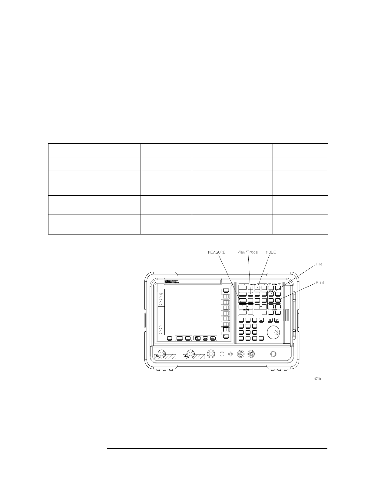
Front-Panel Features
For additional information on those features that are described here,
refer to Chapter 5 , “Front-Panel Key Reference.”
Figure 2-1 Front-Panel Feature Overview
1 Mode keys These keys allow you to select the measurement mode and mode
parameters such as input and trigger settings.
• MODE accesses menu keys to select the instrument mode. Each mode is
independent of all other modes.
• Mode Setup accesses menu keys that allow you to configure the parameters
specific to the current mode and affect all measurements within that mode.
2-2 Chapter2

Rear-Panel Features
This section provides information on only cdmaOne mode features. For
those features not described here, refer to the Agilent ESA Spectrum
Analyzers User’s Guide.
Figure 2-2 Rear-Panel Feature Overview
Getting Started
Instrument Overview
1 DSP and Fast
ADC
DSP and Fast ADC (Option B7D) provides digital signal processing
and fast ADC required for many of the digital demodulation
measurements in the GSM and cdmaOne measurement
personalities.It must beordered with Option B7E and Option 1D5.
2 RF Comms
Hardware
RF Communications Hardware (Option B7E) provides the RF down
convertor hardware required for digital demodulation
measurements. It must be ordered with Option B7D and
Option 1D5
3 Ext Ref In Accepts an external 1 MHz to 30 MHz reference frequency source.
4 10 MHz REF IN Accepts an external frequency source to provide the 10 MHz, −15 to +10
dBm frequency reference used by the analyzer.
Chapter 2 2-3
.

Getting Started
Instrument Overview
5 10 MHz Out Provides a 10 MHz, 0 dBm minimum, timebase reference signal phase
locked to the Ext Ref In.
6 10 MHz REF
OUT
7 Ext Frame
Sync
Provides a 10 MHz, 0 dBm minimum, timebase reference signal.
Accepts an external 0 to 5 V TTL Even Second Clock (ESEC) to provide
the synchronization signal for the frame timer.
Display Annotation
For the screen annotations not described here, refer to the Agilent ESA
Spectrum Analyzers User’s Guide.
Below is an example of the annotation that may appear on an analyzer
display. The display annotation is referenced by numbers which are
listed below.
For examples of particular measurement displays, refer to the results
section for that measurement in the cdmaOne measurement guide.
2-4 Chapter2

Getting Started
Instrument Overview
1
Active Function Area
2
Measurement Bar
3 Current
Measurement
4
Base/Mobile
5
CH Frequency
6
MaxP
7
Standard
8
Averaging Indicator
9
Ext Att/Ext Gain
Displays parameter entries. If you press a key which activates a
function, the parameter description and value will appear in the
active function area.
Displays information about measurements including some mode
setup parameters.
Displays the name of the current measurement.
Indicates which digital communications system platform you are
testing, base station systems or a mobile unit.
Indicates the frequency of the channel you have selected for
measurements.
Indicates the maximum RF input power you have indicated will
be applied to the analyzer.
Indicates which digital communications standard measurements
are being tested to.
Indicates the number of the current average (averagingprogress)
when averaging is turned on.
Indicates the user input value for external attenuation or
preamplifier gain at the RF input.
10
Pass/Fail Status
11
Trig
12
PN Offset
13 Sync ESEC Indicates you have set the Time Reference Sync to ESEC (even
Indicates the statusof the measurementlimit pass/fail test when
one or more limit test function is turned on.
Indicates external triggering mode you have selected for your
measurement: External, Free, RF Burst, or Frame Timer.
Indicates PN offset value you have set for demod measurements.
second clock) for demod measurements. If ESEC is displayed in
red, the even second clock signal has not been connected to the
Ext Frame Sync rear panel connector on the DSP and Fast ADC
module. If ESEC is displayed in black, the even second clock
signal is correctly connected.
Chapter 2 2-5

Getting Started
Options Required
Options Required
One of the following Agilent ESA-E Series Spectrum Analyzers with an
options combination is required to make specific measurements.
Table 2-1 lists the spectrum analyzer models that are compatible and
the upper frequency range of each. You must have one of these
instruments to use the cdmaOne option.
Table 2-1 Compatible Agilent ESA-E Series Spectrum Analyzers
Model Number Upper Frequency Range
E4402B 3 GHz
E4404B 6.7 GHz
E4405B 13.2 GHz
E4407B 26.5 GHz
The cdmaOne measurement personality will have partial functionality
in the ESA without the installation of all additional hardware options
listed. In addition, some measurements require certain options and
other measurements are enhanced by certain options.
Table 2-2 lists the measurements provided by the BAC option and the
options required or recommended for the measurements. For optimum
performance of cdmaOne measurements, Option B74 should be
installed in your Agilent ESA-E Series Spectrum Analyzer.
Not all of the options can be installed by the user. Some of the options
require that the instrument be returned to the factory or an Agilent
Technologies service center. In addition, some of the options require
Performance Verification and Adjustments to be performed after
installation. Refer to Table 2-2 for option specific information.
NOTE When transporting the instrument, use the original packaging or
comparable packaging. If theshipping container is damaged orany part
is missing, notify Agilent Technologies (refer to the ESA-E Series
Spectrum Analyzers cdmaOne Measurement Personality User’s Guide
for locations).
2-6 Chapter2

Table 2-2 cdmaOne Hardware and Software Options
Getting Started
Options Required
Measurements Required or Recommended
Options
Channel Power
Spurs at Harmonics
cdmaOne Measurement
Personality
Occupied Bandwidth
Receive Channel Power
Memory Extension B72
Monitor Band/Channel
Spur Close
Out of Band Spurious
Rx Spur
Channel Power
Spurs at Harmonics
RF and Digital Communication
Hardware Option bundle
Occupied Bandwidth
Modulation Quality (Rho)
Code Domain
Receive Channel Power
Monitor Band/Channel
Spur Close
Out of Band Spurious
Rx Spur
Includes the following options:
1D6
B72
1D5
B7D
B7E
1DS
1DR
Modulation Quality (Rho)
DSP and Fast ADC
a
Code Domain
RF Communications Hardware
High Stability Frequency
Reference
b
Option Remarks
BAC Required options for
any cdmaOne
measurements.
B74 This is the preferred
a
option to install with
Option BAC. It
containsallhardware
necessary to perform
all measurements
andbundle packaging
makes it easy to
order.
B7D These options enable
digital demodulation
a
B7E
measurements and
must be ordered
1D5
together.
Receive Channel Power
Preamplifier
b
Monitor Band/Channel
Spur Close
Out of Band Spurious
10 Hz Narrow Resolution
Bandwidth Option
b
Rx Spur
Distance to Fault
50 Ohm Tracking Generator
b
Distance to Fault HDF
a. Factory or Service Center installation, calibration required.
b. Factory installation only
Chapter 2 2-7
.
1DS These options
enhance the
1DR
sensitivity for these
measurements and
can be ordered
together with
Option 1D5 as the
Performance Option
Bundle B75.
1DN These options allow
Distance to Fault
measurement.
Option 1DNgivesyou
theabilityto measure
SWR and Flatness.

Getting Started
Options Required
When you select the cdmaOne mode, the spectrum analyzer performs a
hardware check. The available hardware is compared to the cdmaOne
measurement personality hardware requirements. For example, if
Option B7D and Option B7E hardware is not present, the
Mod Accuracy (Rho) and Code Domain Power keys will be grayed out on
the
MEASURE menu and will not be available for use.
2-8 Chapter2

cdmaOne Documentation for the ESA-E Series Spectrum Analyzers
cdmaOne Documentation for the ESA-E Series
Spectrum Analyzers
Spectrum Analyzers with cdmaOne Installed
When you purchase your instrument with the cdmaOne measurement
personality, you receive the following materials:
Table 2-3 Personality Documentation
Part Number Part Description Notes
Getting Started
Refer to the ESA
WEB site for the
current part
number.
User’s Guide
ESA-E Series Spectrum Analyzers
cdmaOne Measurement Personality
Quick Reference Card
ESA-E Series Spectrum Analyzers
cdmaOne Measurement Personality
Measurement Guide
ESA-E Series Spectrum Analyzers
cdmaOne Measurement Personality
Programming Commands
ESA-E Series Spectrum Analyzers
cdmaOne Measurement Personality
Agilent ESA Spectrum Analyzers
Specifications Guide
Agilent ESA Spectrum Analyzers
Documentation and Instrument
Driver CD-ROM
BAC Option manuals
BAC Option manuals
BAC Option manuals
BAC Option manuals
Includes specifications for
all optional measurement
personalities
Does not include service
documentation or software
Chapter 2 2-9

Getting Started
cdmaOne Documentation for the ESA-E Series Spectrum Analyzers
Spectrum Analyzers without cdmaOne Installed
If your instrument is ordered without measurement personalties
installed, you can order the cdmaOne measurement personality
Option BAC and Option B74
purchase of a personality option upgrade, you receive the documents
listed in Table 2-3 and the documents shown below in Table 2-4.
Table 2-4 Personality Documentation
Part Number Part Description Notes
1
instrument upgrade package. With the
Refer to the ESA
WEB site for the
current part
number
Understanding Digital Communications
Measurements
Additional measurement application information is available through
your local Agilent Technologies sales and service office. Refer to “Other
Sources of Measurement Information” on page 1-7 for application notes.
ESA Spectrum Analyzers Update
For the latest information about this instrument, including software
upgrades, application information, and product information, please
visit the URL listed below.
Updating the Firmware and Software
Updated versions of the AgilentESA Spectrum Analyzers firmware and
software will be available via several sources. Information on the latest
firmware and software revision can be accessed through the following
URL.
RF and Digital Communications
Hardware Installation Note
B74 Option manual
URL to Obtain Update Information
http://www.agilent.com/find/esa/
1. Refer to Table 2-2 for option details.
2-10 Chapter2

Getting Started
Installing Optional Measurement Personalities
Installing Optional Measurement
Personalities
Active License Key
The measurement personality software you have purchased with your
instrument has been installed and the license key has been enabled at
the factory. With any future purchase of a new personality software,
you will receive a certificate that displays the unique license key
number. The license key enables you to install, or reinstall, any
measurement personality you have purchased.
You will want to keep a copy of your license key number in a secure
location. Please enter your license key numbers in the box provided
below for future reference. If you should lose your license key number,
get in touch with your local Agilent Technologies service or sales office
for assistance. For the location of these offices, refer to Table 6-1 on
page 6-5.
Active License Key Numbers for Instrument with Serial # ________
For Option______________ the license number is ________________________
For Option______________ the license number is ________________________
For Option______________ the license number is ________________________
You will need to use a license key number only under the following
conditions:
• If you purchase an additional measurement software package.
• If the controller board is repaired or replaced.
Installing the Licensing Key
If you are installing a new option, follow these steps to install the
unique license key number for the measurement personality software
that you want to install in your instrument:
1. Press
When you press
instructions on using the alpha editor, refer to the ESA Spectrum
Analyzers User’s Guide.
System, More, Licensing, Option.
Option the alpha editor will be activated. For
2. Use the alpha editor to enter the three letter designation for the
software option that you wish to install in the instrument.
3. Press
Chapter 2 2-11
Done on the alpha editor menu.

Getting Started
Installing Optional Measurement Personalities
4. Press License Key.
When you press
Licensing Key the alpha editor will be activated. For
instructions on using the alpha editor, refer to the ESA Spectrum
Analyzers User’s Guide.
5. Use the alpha editor to enter the 12 character licensing key number
for the software option that you wish to install in the instrument.
6. Press
7. Press
Done on the alpha editor menu.
Activate to turn on the licensing key. You may now install the
measurement personality option software.
Using Install Key
You may want to install a software revision, install new measurement
software, reinstall measurement software that you have previously
uninstalled, or uninstall measurement software. Before you can install
software, you will need a set of installation diskettes.
If you have ordered a measurement personality, you will receive the
installation disk set in the option upgrade package. If you are updating
an existing, previously installed measurement option, you may order
the diskettes from Agilent Technologies or create a set from the Agilent
internet site shown in “ESA Spectrum Analyzers Update” on page 2-10.
When you order the updated software disk set, you will need to order
Option UE2 with an cdmaOne revision update. (Option UE2 is a
firmware update and is needed to ensure that the firmware and the
software are compatible.) To order a set of diskettes, get in touch with
your local Agilent Technologies service or sales office.Forthe locationof
these offices, refer to Table 6-1 on page 6-5. To create a disk set refer to
“Creating Software Installation Disks” below.
Creating Software Installation Disks
To create the installation disks on-line, visit the Agilent internet site
shown under “ESA Spectrum Analyzers Update” on page 2-10. Follow
the instructions provided on the internet site for downloading the
current measurement personalty software and creating the installation
disk set. The instructions for creating the disk set will step you through
the process to create a firmware disk set when you create the
measurement personalty software disk set. (A firmware update may be
needed to ensure that the firmware and the software are compatible.)
After you have created the disk set, follow the on-line instructions to
install the firmware. After successfully installing the firmware update,
proceed with the following instructions for installing the measurement
personalty software in your instrument.
2-12 Chapter2

Getting Started
Installing Optional Measurement Personalities
Installing Personality/Software Options
This procedure gives steps to install a new software option in an ESA-E
Series Spectrum Analyzer using the internal floppy drive of the
instrument. Screen messages display the update progress and give
directions. The instrument will not need to be re-calibrated after this
procedure since no changes are made to calibration or adjustment files.
If you have a problem with the installation process, refer to
“Troubleshooting the Installer” on page 2-14.
NOTE When the installer starts up, it examines the instrument to ensure that
all the required software and hardware options are present. If they are
not, the installer will generate and error and you will not be able to
install the personality.
1. If this is the installation of new personality option software, you
must enter the License Key for the new option. For instructions on
entering the License Key, refer to the “Installing the Licensing Key”
on page 2-11.
When you have completed entering the license key number, continue
with the next step.
2. Insert disk one of the installation disk set into the disk drive located
on the right side of the ESA front panel.
3. Press
System, More, Personalities, and Install. The instrument will
then load the installer off of the floppy drive. If there is no floppy in
the drive, the incorrect diskis inserted,or thereis no installer on the
disk, the error “No install disk present in disk drive” will be shown.
Once the instrument has loaded the installer, the screen will change
to the installer screen and the
Install Pers. menu will be shown. For
more information on the installer screen and menu, refer to
“Installer Screen and Menu” on page 2-15.
4. When the installer first starts up, it will show a popup message.
Select
NOTE Once the installer has begun installing a personality, any error will
Verify Disks.
cause the whole personality (including a previously installed version) to
be removed from the instrument. Because of this, it is very important
that you verify the disks prior to installing them. If any of the disks or
files are bad, you will not be able to use the personality until you obtain
a new installation disk set and run the install using them.
5. When prompted, insert the next disk and press
When Verify Disks is running, the
Install Now and Exit Install keys
Verify Disks again.
will be greyed out.
Chapter 2 2-13

Getting Started
Installing Optional Measurement Personalities
6. When the verification is complete, press Install Now and the
installation of the personality will begin. Some of the disks may take
only a short time to load or be skipped entirely, while others can take
up to about 30 minutes to load.
When installer is running, the
Verify Disks and Exit Install keys will
be greyed out.
7. When prompted, insert the next disk and press Install Now again.
8. Once the installation is complete, press
Exit Install.
Troubleshooting the Installer
If the installation process stalls or fails in another way, follow these
steps to resolve your problem.
1. If the instrument stops the update process before all the disks are
loaded proceed as follows:
a. Press
Exit Install to abort the process.
b. Return to step 2 on the previous page and start the installation
process again.
2. If the instrument fails after repeating the installation procedure, get
in touch with your nearest Agilent sales and service office listed in
Table 6-1 on page 6-5 for assistance. Please provide the following
information:
Model Number:
Serial Number:
State that you are having trouble installing a software option
update.
2-14 Chapter2

Getting Started
Installing Optional Measurement Personalities
Installer Screen and Menu
The top portion of the install screen is a table in which the files that are
about to be installed are listed. The bottom portion of the screen
contains information needed to track the progress of the install.
1 File Table displays the files to be installed and various file
information. If there are more then six files, Next Item and Prev Item
allow you to scroll the table to view additional items.
2 File Name displays the name of the files on the installation disk.
3 Current Version displays the version of the file that is currently
installed in the instrument. (This field will be blank if this file is not
currently installed in the instrument or if the file is a data file that has
no version.)
4 Upgrade Version shows the version of the file on the install disk.
This is the version of the file that will replace the currently installed
version.
5 Status is updated to reflect what the installer is doing to the current
file as the install progress. The valid messages seen in this column are
listed in Table 2-5 on page 2-16.
6 Data Field contains a status bar and various status information.
7 Processing disk shows the disk that is currently being read.
8 Processing item shows the file that is being processes by item
number.
9 Bytes free on C is the number of bytes currently free on the
instrument C: drive.
Chapter 2 2-15

Getting Started
Installing Optional Measurement Personalities
10 Status Bar contains a status bar that runs from 0 to 100% and tracks
the progress of the current step and a message line displays the step
that is currently being executed.
11 Bytes in package lists the number of bytes in the install package/ fill.
12 Bytes left in package lists the number of bytes left to be read.
13 Message and error popup window that displays over the status bar.
Information in this box will prompt you for action required to proceed
to the next phase of the installation.It may also inform you of errors in
the installation process and may prompt you for action required to
correct the problem.
Table 2-5 Installer Status Messages
Failed This means that something has gone wrong while processing
this item. It is a fatal error and the installation can not be
completed. The installer will try to get the system back to a
good state which may entailcompletely removing the currently
installed personality.
Loading The file is currently being copied from the install media to the
instrument’s file system.
Verifying This may mean one of two things:
1. If “Verify Disks” was pressed then Verifyingmeans that the
installer is currently reading the install media and
comparing the known checksums to ensure the data is good.
2. If “Install Now”was pressed, then Verifying means that the
installer is reading what was just loaded to ensure the
checksum is correct.
Loaded This means that the data has been placed on the instrument
disk but has not yet been registered with the firmware.
Installed This means that the data has been loaded into the instrument
and registered. The install for this file is complete.
Skipping This means that the installer has determined that this file
does not need to be loaded into the instrument.
2-16 Chapter2

3 Setting Up the cdmaOne Mode
This chapter introduces you to the basic measurement process.
3-1

Setting Up the cdmaOne Mode
Preparing to Make Measurements
Preparing to Make Measurements
At initial power up, the analyzer will be in spectrum analyzer (SA)
mode and the
cdmaOne measurement personality, press the
cdmaOne key.
Initial Settings
Before making a measurement, make sure the mode setup and
frequency channel parameters are set to the desired settings. Refer to
sections Chapter 4 , “Menu Maps,” and Chapter 5 , “Front-Panel Key
Reference,” for additional information to guide you in changing
parameter settings.
If you want to set the instrument (including the cdmaOne mode
settings) to a known, factory default state,press
the mode setup and all of the measurement setup parameters to the
factory default parameters. Note that
returning the ESA to the SA mode. You must re-access the cdmaOne
mode after the preset operation is completed.
FREQUENCY Channel menu displayed. To access the
Mode key and select the
Preset. This will preset
Preset will switch modes,
You can set the instrument to use User preset or Factory preset under
the
System front panel key. If you set the preset to User, the
instrument displays a Preset menu when you press
menu allows you to select the
User defaults or the Factory defaults. For
Preset. The Preset
more information on setting, saving, and using user defaults, refer to
the ESA Spectrum Analyzers User’s Guide.
If you want to set only the cdmaOne mode to a known, factory default
state, press
Mode Setup and Restore Mode Defaults. This will reset only
the cdmaOne parameters to the factory defaults without affecting the
SA mode, and the instrument will not exit the cdmaOne mode.
To preset only the settings that are specific to the selected
measurement, press
Restore Meas Defaults under Meas Setup. This will
set the measurement setups parameters, for the currently selected
measurement only, to the factory defaults.
How to Make a Measurement
The cdmaOne measurements are set up and are intended to be used as
“one-button” measurements. After you have properly connected the
instrument to the digital communications system equipment and
selected the measurement, the measurement is made using the default
parameters defined by the selected standard and the tuning plan.
3-2 Chapter3
Setting Up the cdmaOne Mode
Preparing to Make Measurements
Even though the measurements are designed as one-button
measurements, you may change the default settings using various
setup keys. However, changing the default settings may produce
measurement results that are outside of the parameters of the selected
standard and tuning plan requirements.
Most measurements can be performed using the simple four-step
procedure outlined in the table below. Most measurements are
performed using only the primary keys listed in conjunction with a
minimum of setup keys. Measurement setup keys (
Meas Setup) can be
used for non-standards compliant testing. For more information see
“Initial Settings” above.
Step Primary Key Setup Keys Related Keys
1. Select and setup mode MODE Mode Setup System
2. Select and setup
measurement
3. Select and setup view View/Trace Span X Scale,
4. Saving and printing
results
MEASURE Meas Setup,
Restore Meas Defaults,
FREQUENCY Channel
Amplitude Y Scale
File
Print
Print Setup Save
, Display
Meas Control
Restart
, Search
Marker
,
Chapter 3 3-3

Setting Up the cdmaOne Mode
Preparing to Make Measurements
How to Save Measurement Results
To save measurement results, follow the process shown below. For
additional information on file management in the spectrum analyzer,
refer to the ESA Spectrum Analyzers User’s Guide.
1. Press
2. If you want to change the file name, press
File, Save, Type, More, Measurement Results.
Return, Name, and use the
Alpha Editor the enter thenew name. For moreinformation on using
the Alpha Editor, refer to the ESA Spectrum Analyzers User’sGuide.
3. Press
Save Now to complete the file saving process.
4. If you have used the default file name and wish to save additional
measurement results, press Save. The current measurement result
will be saved with the next default file name.
5. If you have not used the default file name and wish to save
additional measurement results, repeat steps 1 through 3.
3-4 Chapter3

4 Menu Maps
This chapter provides a visual representation of the front-panel keys
and their associated menu keys. Refer to Chapter 5 , “Front-Panel Key
Reference,” for key function descriptions.
4-1

Menu Maps
What You Will Find in This Chapter
What You Will Find in This Chapter
This chapter provides menu maps for the front panel keys having
associated menus. The key menus appear in alphabetical order as
follows:
AMPLITUDE Y Scale Page 4-3
Display Page 4-4
File Page 4-5
FREQUENCY Channel Page 4-6
Input/Output Page 4-7
Installer Page 4-8
MEASURE Page 4-9
Measurement Setup—Channel Power Page 4-10
Measurement Setup—Code Domain Page 4-11
Measurement Setup—Mod Accuracy (Rho) Page 4-12
Measurement Setup—Monitor Band/Channel Page 4-13
Measurement Setup—Occupied Bandwidth Page 4-14
Measurement Setup—Out of Band Spurious Page 4-15
Measurement Setup—Receive Channel Power Page 4-16
Measurement Setup—Receiver Spurious Page 4-17
Measurement Setup—Spur Close (In Band Spurs) Page 4-18
Measurement Setup—Spurs at Harmonics Page 4-19
MODE Page 4-20
Mode Setup Page 4-21
SPAN X Scale Page 4-22
Trig Page 4-23
View/Trace Page 4-24
4-2 Chapter4

Menus
Amplitude Menu
Menu Maps
Menus
Chapter 4 4-3

Menu Maps
Menus
Display Menus
4-4 Chapter4

File Menus
Menu Maps
Menus
Chapter 4 4-5

Menu Maps
Menus
Frequency/Channel Menu
4-6 Chapter4

Input/Output Menu
Menu Maps
Menus
Chapter 4 4-7

Menu Maps
Menus
Installer Menus
For more information on the System and Personalities menus, refer to
the ESA Spectrum Analyzers User’s Guide.
4-8 Chapter4

Measure Menu
Menu Maps
Menus
Chapter 4 4-9

Menu Maps
Menus
Measurement Setup Menus
Channel Power Measurement Setup Menus
4-10 Chapter4

Code Domain Measurement Setup Menus
Menu Maps
Menus
Chapter 4 4-11

Menu Maps
Menus
Modulation Accuracy (Rho) Measurement Setup Menus
4-12 Chapter4

Monitor Band/Channel Measurement Setup Menus
Menu Maps
Menus
Chapter 4 4-13

Menu Maps
Menus
Occupied Bandwidth Measurement Setup Menus
4-14 Chapter4

Out of Band Spurious Measurement Setup Menus
Menu Maps
Menus
Chapter 4 4-15

Menu Maps
Menus
Receive Channel Power Measurement Setup Menus
4-16 Chapter4

Receiver Spurious Measurement Setup Menus
Menu Maps
Menus
Chapter 4 4-17

Menu Maps
Menus
Spur Close (In Band Spurious) Measurement Setup Menus
4-18 Chapter4

Spurs at Harmonics Measurement Setup Menus
Menu Maps
Menus
Chapter 4 4-19

Menu Maps
Menus
Mode Menu
4-20 Chapter4

Mode Setup Menus
Menu Maps
Menus
Chapter 4 4-21

Menu Maps
Menus
Span (X Scale) Menu
4-22 Chapter4

Trigger Menu
Menu Maps
Menus
Chapter 4 4-23

Menu Maps
Menus
View and Trace Menus
4-24 Chapter4

Menu Maps
Menus
Chapter 4 4-25

Menu Maps
Menus
4-26 Chapter4

5 Front-Panel Key Reference
This chapter details the front-panel keys and menu keys that appear on
the menu-maps presented in the previouschapter. The front-panel keys
are listed alphabetically and are described with their associated menu
keys. The menu keys are arranged as they appear in your analyzer
menus.
5-1

Front-Panel Key Reference
Key Descriptions and Locations
Key Descriptions and Locations
This chapter provides information on only cdmaOne mode functions.
The keys that are described are not available in the SA mode. In
addition, keys that provide functions in cdmaOne mode that differ from
the functions provided by that same key in the SA mode are described.
Some keys provide less functions in cdmaOne mode than in the SA
mode. However, the functions that are provided are identical to those
provided in the SA mode.For those keys not described here, refer to the
ESA Spectrum Analyzers User’s Guide.
AMPLITUDE Y Scale Page 5-4
Det/Demod Page 5-6
Display Page 5-7
FREQUENCY Channel Page 5-8
Input/Output Page 5-9
Installer Page 5-11
Meas Setup—Channel Power Page 5-13
Meas Setup—Code Domain Page 5-16
Meas Setup—Mod Accuracy (Rho) Page 5-19
Meas Setup—Monitor Band/Channel Page 5-22
Meas Setup—Occupied Bandwidth Page 5-26
Meas Setup—Out of Band Spurious Page 5-29
Meas Setup—Receive Channel Power Page 5-32
Meas Setup—Receiver Spurious Page 5-35
Meas Setup—Spur Close (In Band Spurs) Page 5-38
Meas Setup—Spurs at Harmonics Page 5-41
MEASURE Page 5-44
Measurement—Channel Power Page 5-44
Measurement—Code Domain Page 5-45
Measurement—Mod Accuracy (Rho) Page 5-46
Measurement—Monitor Band/Channel Page 5-47
Measurement—Occupied Bandwidth Page 5-47
Measurement—Out of Band Spurious Page 5-49
Measurement—Receive Channel Power Page 5-49
5-2 Chapter5

Key Descriptions and Locations
Measurement—Receiver Spurs (Rx Spur) Page 5-50
Measurement—Spur Close (In Band Spurs) Page 5-51
Measurement—Spurs at Harmonics Page 5-54
MODE Page 5-55
Mode Setup Page 5-56
Preset Page 5-61
SPAN X Scale Page 5-62
Trig Page 5-63
View/Trace Page 5-64
Front-Panel Key Reference
Chapter 5 5-3

Front-Panel Key Reference
AMPLITUDE Y Scale
AMPLITUDE Y Scale
Activates the reference level function, if it is available,and accesses the
amplitude menu keys. Amplitude menu keys are used for setting
functions that affect the way data on the vertical axis is displayed or
corrected.
Ref Level If RF Input Range is set to manual, this key allows the reference level
to be changed. This function is activated when
pressed. The reference level is the amplitude power or voltage
represented by the top graticule line on the display.Changing the value
of the reference level changes the absolute amplitude level (in the
selected amplitude units) of the top graticule line. The reference level
can be changed using the step keys, the knob, or the numeric keypad.
Pressing any digit, 0 through 9, on the numeric keypad brings up the
terminator menu.
AMPLITUDE Y Scale is
This key is grayed out and not available when
Auto on the Input form.
Attenuation Sets the input attenuation in 5 dB increments. The analyzer input
RF Input Range is set to
attenuator, which is normally coupled to the reference level control,
reduces the power level of the analyzer input signal at the input mixer.
Attenuation can be changed using the step keys, the knob, or the
numeric keypad.
This key is grayed out and not available when
Auto on the Input form.
NOTE Step keys and knob can not be used to set Atten = 0. To set the
RF Input Range is set to
attenuator to 0 dB you must use the keypad.
CAUTION To prevent damage to the input mixer, do not exceed a power level of
+30 dBm at the input. To prevent signal compression, keep the power
at the input mixer below 0 dBm. With the attenuator set to Auto, a
signal at or below the reference level will result in a mixer level at or
below –10 dBm.
Scale/Div Sets the logarithmic units per vertical graticule division on the display.
Scale/Div values may range from 0.1 to 20 dB per division.
Power Scale/Div When the Code Domain measurement has been selected, this key
allows you to set the logarithmic units per vertical graticule division on
the Power Graphic display. Scale/Div values may range from 0.1 to
20 dB per division.
5-4 Chapter5

Front-Panel Key Reference
AMPLITUDE Y Scale
Timing Scale/Div When the Code Domain measurement has been selected, this key
allows you to set the units per vertical graticule division on the Timing
Graphic display. Scale/Div values may range from 1 ns to 1 s per
division.
Phase Scale/Div When the Code Domain measurement has been selected, this key
allows you to set the logarithmic units per vertical graticule division on
the Phase Graphic display. Scale/Div values may range from 1 mrad to
62.8 rad per division.
Chapter 5 5-5

Front-Panel Key Reference
Det/Demod
Det/Demod
This front panel key accesses the Demod data form and a set of menu
keys controlling parameters to demodulation functions. For additional
information on the data form and menus, refer to
page 5-58.
Demod… on
5-6 Chapter5

Front-Panel Key Reference
Display
Display
This front panel key accesses the menu key that allows you to see and
setup different measurement displays. For cdmaOne, it is used for the
Modulation Accuracy (Rho) measurement.
I/Q Points Allows you to set the number of I/Q points used in the display.
Points/Chip Allows you to select the number of points for the trace to be
interpolated to 1, 2, or 4 points/chip.
1 = only the decision points
2 = the decision points with one point between them
4 = the decision points with three points between them
NOTE With Points/Chip set to 1, only chip dots are displayed; no transition
points are seen.
Chip Dots Allows you to set the chip dot function to On or Off.
On Enables the chip dots and they are shown on the
display.
Off Disables the chip dots and they are not shown on the
display.
NOTE With Points/Chip set to 1, chip dots are always displayed independent of
the Chip Dots setting.
Chapter 5 5-7

Front-Panel Key Reference
FREQUENCY Channel
FREQUENCY Channel
This front panel key activates the RF Channel Number function, and
accesses the menu of frequency functions. The center frequency values
appear below the graticule on the display.
NOTE When changing both the center frequency and the span, change the
frequency first since the span can be limited by the frequency value.
RF Channel Activates the RF channel number function allowing you to tune the
analyzer frequency by channel number.
Channel Freq Activates the channel frequency function allowing you to enter the
center frequency of the channel of interest.
Temp Ctr Freq Activates the temporary center frequency function allowing you to
enter a frequency to temporarily change the channel frequency. The
temporary center frequency will only be effective for the current
measurement when selected. If the measurement is restarted or
reselected, the centerfrequency is reset based onthe channel frequency.
The measurements affected by this key are Channel Power, Receive
Channel Power, Rho, Code Domain, Monitor Band/Channel, and
Occupied Bandwidth.
CF Step
Auto Man
Changes the step size for the Channel Frequency and Temp. Center
Freq. function. Once a step size has been selected and the channel
frequency or temporary frequency function is activated, the step keys
change the frequency by the step-size value. The step size function is
useful for finding harmonics and sidebands beyond the current
frequency span of the analyzer. When auto-coupled, the center
frequency step size is set to one channel width as defined by the
selected Standard and tuning plan.
PN Offset Activates the PN offset function allowing you to enter the PN Offset
(also called Time Offset) of the base station being tested. This enables
the instrument to determine the correct time offset values.
Time Offset indicates how well your transmitter signal is time-aligned
to system time. The displayed measurement results value takes into
account the PN Sequence Offset Index of your transmitter that you
entered using the
PN Offset key is duplicated in the Demod form under various
PN Offset key. The range is 0 to 511 × 64[chips]. The
measurements and under Mode Setup.
5-8 Chapter5

Front-Panel Key Reference
Input/Output
Input/Output
This front panel key accesses the Input form and menu keys that allow
you to set various input parameters affecting all measurements. These
settings will not change if you leave and return to the cdmaOne mode.
RF Input Range Accesses menu keys for you to select Auto or Manual function for the RF
input range. If
internal input attenuator and reference level based on the power level
of the tuned carrier. If there are multiple carriers present, the total
power might overdrive the front end. In this case you need to set the
RF Input Range to Manual and enter the expected Max Total Pwr. Manual is
also used if you want to hold the input attenuation constant (for the
best relative power accuracy). For single carriers it is generally
recommended to set the
Auto Allows auto ranging based on input signal power
Auto is chosen, the instrument automatically sets the
RF Input Range to Auto.
automatically setting the reference level and
attenuation.
Manual Sets the instrument to use the custom values for the
input range that you enter by accessing the
Max Total Pwr and Input Atten parameter fields described
below.
NOTE For Mod Accuracy (Rho) and Code Domain, Auto is always used and
any user entered parameters are ignored.
NOTE If Noise Correction and RF Input Range are both set to Auto, the internal
input attenuator and reference level will only be set one time and not
automatically update. Achange in the input signallevel may require an
update of the internal input attenuator and reference level. In that
case, you will need to press
Restart to take a new measurement and
reset the input attenuator and reference level. This will invalidate the
noise floor calibration. You will then be prompted to perform another
Noise Floor Calibration or to set
Noise Correction to Off before
proceeding with the measurement.
Max Total Pwr Allows you to set the maximum total power at the UUT (Unit Under
Test). This is the maximum expected value of the mean carrier power
referenced to the output of the UUT (may include multiple carriers).
The Max Total Pwr setting is coupled to the
Changing
Max Total Power will set the RF Input Range to Manual.
Input Atten setting.
Chapter 5 5-9

Front-Panel Key Reference
Input/Output
Input Atten Allows you to set the input attenuator setting. The Input Atten setting
is coupled to the Max Total Pwr setting.The
Input Atten key displays the
actual internal input attenuator value. Changing the input attenuation
will set the
NOTE The Max Total Pwr and Input Atten settings are coupled together, so for a
given measurement, changing the input
the
Input Atten by n dB, and vice-versa. Thus, you can directly set the
RF Input Range to Manual.
Max Total Pwr by n dB changes
analyzer input attenuation, or you can set it indirectly by specifying the
maximum expected power at the UUT (Max Total Pwr setting).
BS Ext Atten Allows you to enter the value for any attenuators used between the
UUT and the analyzer. This will allow the instrument to display the
measurement results referenced to the output of the UUT. This
attenuation value is used by all measurements except
Rx Channel Power.
Ext Gain Allows you to enter the external gain value of any amplifiers between
Rx Spur and
the UUT and the analyzer. This will allow the instrument to display the
measurement results referenced to the output of the UUT. This
amplification value is used by only the
Rx Spur and Rx Channel Power
measurements.
5-10 Chapter5

Front-Panel Key Reference
Installer
Installer
This menu key, under the System and Personalities keys, accesses the
Installer menu keys that allow you to install optional measurement
personality software.
Next Item This allows you to scroll down the table of files being installed. This key
will be grayed out if the last item is currently being shown.
Prev Item This allows you to scroll up the table of files being installed. This key
will be grayed out if the first item is currently being shown.
Verify Disks This initiates the disk validation process causing the installer to read
the install disks and validate the checksums for all the files. Once the
installer has read a complete disk, a prompt pop-up will be shown
which will request you to insert the next disk and press
again. When the disk verification is running, Install Now and Exit Install
will be grayed out.
Verify Disks
Install Now This initiates the installation process causing the installer to begin the
installation of the personality. It will begin reading the first disk. Its
progress can be tracked in the status bar and the file table Status field.
Once the current disk has been read, a popup will be shown requesting
you to insert the next disk and press
installation is running,
Verify Disks and Exit Installation will be grayed
Install Now again. When
out.
Abort Install This key is active when Install Now or Verify Disks has been pressed. It
allows you to interrupt the current install. When pressed, it will put up
a pop-up message which asks if the user really wants to abort.
Depending on how far the installer got, aborting the install may cause
the installer to completely remove the currently installed personality.
Before aborting the process and removing the installed personality, the
installer will display a warning message.
Exit Install This causes the installer to exit the installation program and returns
you to the SA mode.
Chapter 5 5-11

Front-Panel Key Reference
Meas Setup
Meas Setup
Displays a menu that allows the user to enter custom setup parameters
for a measurement. The setup menu displayed depends on the
measurement selected in the
measurements to see specific parameters that can be accessed.
MEASURE menu. Refer to individual
5-12 Chapter5

Front-Panel Key Reference
Channel Power Measurement Setup
Channel Power Measurement Setup
To access the following keys for setting up a Channel Power
measurement, press
Meas Setup key.
Meas Setup
Displays a menu that allows the user to enter custom setup parameters
for a measurement. The setup menu displayed depends on the
measurement selected in the
MEASURE, Channel Power and then the front panel
MEASURE menu.
Avg Number
On Off
Allows you to specify the number of measurements that will be
averaged. After the specified number of average counts, the
Avg Mode
setting determines the averaging action. You can also set the averaging
function to
On Enables the measurement averaging.
Off Disables the measurement averaging.
NOTE Trace values are not averaged. Measurement result values averaged.
Avg Mode Allows you to select the type of termination control used for the
On or Off.
averaging function. This determines the averaging action after the
specified number of measurements (average count) is reached.
Exp Each successive data acquisition after the average
count is reached, is exponentially weighted and
combined with the existing average.
Repeat After reaching the average count,the averaging is reset
and a new average is started.
Integ BW Allows you to specify the channel integration bandwidth used in
calculating the power in the channel. This bandwidth is normally
1.23 MHz.
Chan Pwr Span Allows you to set the analyzer span for the Channel Power
measurement.
Noise Correction Allows you to set the noise floor correction function to Auto or Off.
Noise floor correction removes the effects of analyzer noise, improving
accuracy when necessary. Thecorrection is applied when channelpower
is less than the noise correction threshold (set on the
under
Mode Setup) above the measured analyzer noise floor. Noise
Properties… form
Corrected appears in the lower left corner of the measurement results
area to indicate that noise correction is being applied.
Chapter 5 5-13

Front-Panel Key Reference
Channel Power Measurement Setup
When channel power is less than the analyzer noise floor, the error
message CH Power < SA Noise Pwr, Pwr Accuracy Degraded is
displayed. When channel power is below this level, the measurement
uncertainty is too large to makea reliable measurement. The minimum
displayable noise-corrected channel power is 6 dB below the analyzer
noise floor.
On Enables the measurement noise correction, when
needed.
Off Disables the measurement noise correction.
NOTE The current Noise Floor Calibration will be invalid if any of the
following are changed:resolution bandwidth (
Res BW), video bandwidth
(Video BW), Channel Freq, Ref Level, or Span.
NOTE If Noise Correction and RF Input Range are both set to Auto, the internal
input attenuator and reference level will only be set one time and not
automatically update. Achange in the input signallevel may require an
update of the internal input attenuator and reference level. In that
case, you will need to press
Restart to take a new measurement and
reset the input attenuator and reference level. This will invalidate the
noise floor calibration. You will then be prompted to perform another
Noise Floor Calibration or to set
Noise Correction to Off before
proceeding with the measurement.
Limits… Accesses the limits data form and associated limit menus allowing you
to set the upper and lower pass/fail limits for the Channel Power
measurement.
Chan Pow Allows you to set the value for the pass/fail limit test.
The upper and lower limits are set and enabled
separately.
On Enables the pass/fail test.
Off Disables the pass/fail test.
Restore Meas
Defaults
Sets up the instrument parameters for the measurement using the
factory default instrument settings. (This only affects measurement
parameters for this measurement and does not affect any mode
parameters.) If you have made any manual changes to the
measurement parameters, restoring the measurement defaults will
ensure standard compliant measurements.
5-14 Chapter5

Front-Panel Key Reference
Channel Power Measurement Setup
Advanced Accesses an advanced function menu allowing you to set Channel
Power measurement parameters for
Res BW Allowsyou to set the resolution bandwidth used for the
measurement and to set the function mode to
Man.
Auto Sets the resolution bandwidth mode to
Res BW, Trigger, and Max Mixer Lvl.
Auto or
automatic using the calculated default
bandwidth value.
Man Sets the resolution bandwidth mode to
manual using the user-defined
bandwidth.
Trigger Accesses the trigger source menu allowing you to set
the source that will be used for the measurement.
Free Run The next measurement is immediately
taken, capturing the signal
asynchronously (also called
immediate).
External Uses the rear panel external trigger
input signal to trigger the
measurement.
Max Mixer Lvl Allows you to set themaximum power level at the input
of the mixer for the measurement. The instrumentuses
this value to automatically set the required input
attenuation to maintain the mixer input power below
this level.
Chapter 5 5-15

Front-Panel Key Reference
Code Domain Measurement Setup
Code Domain Measurement Setup
To access the following keys for setting up a Code Domain
measurement, press
Meas Setup key.
Meas Setup
Displays a menu that allows the user to enter custom setup parameters
for a measurement. The setup menu displayed depends on the
measurement selected in the
MEASURE, Code Domain and then the front panel
MEASURE menu.
Avg Frames
On Off
Accesses the averaging function allowing you to specify the number of
measurements that will be averaged. After the specified number of
average counts, the averaging mode (termination control) setting
determines the averaging action. You can also set the averaging
function to
On Enables the measurement averaging.
Off Disables the measurement averaging.
NOTE The scalar results values are averaged–not trace values–when
Avg Frames is set to On.
Avg Mode Allows you to select the type of termination control used for the
On or Off.
averaging function. This determines the averaging action after the
specified number of measurements (average count) is reached.
Exp After the average count is reached, each successive
data acquisition is exponentially weighted and
combined with the existing average.
Repeat After the average count is reached, the averaging is
reset and a new average is started.
Meas Interval Allows you to set the length of the measurement interval.
Method Accesses menu keys allowing you to set the measurement method to
Power or Timing and Phase.
Power Measures the code domain power of all 64 Walsh
channels.
Timing
and Phase Measures the code domain power, code domain timing,
and code domain phase of all active Walsh channels.
5-16 Chapter5

Front-Panel Key Reference
Code Domain Measurement Setup
Act Set Th Allows you to set the active code channel threshold value. Walsh
channels with power less than this value, will be treated as Inactive
traffic channels.
Spectrum Allows you to set the measurement demodulationspectrum to Normal or
Invert.
Normal The normal spectrum is used
Invert Specifies phase inversion where the sign of ‘Q’ is
reversed.
Demod… Accesses the demod setup form and menu keys. Refer to Demod… on
page 5-58 for additional information.
Limits… Accesses the limits data form and associated menus allowing you to set
the upper or lower pass/fail limits for the measurement.
Est. Rho Estimated Rho allows you to set the value for the
pass/fail limit test.
Restore Meas
Defaults
On Enables the pass/fail test.
Off Disables the pass/fail test.
Relative Time Allows you to set the value for the pass/fail limit test
when method is set to Timing Phase. When this test is
enabled, each Walsh code channel is tested against this
limit.
On Enables the pass/fail test.
Off Disables the pass/fail test.
Relative Phase Allows you to set the value for the pass/fail limit test
when method is set to Timing Phase. When this test is
enabled, each Walsh code channel is tested against this
limit.
On Enables the pass/fail test.
Off Disables the pass/fail test.
Sets up the instrument parameters for the measurement using the
factory default instrument settings. (This only affects measurement
parameters for this measurement and does not affect any mode
parameters.) If you have made any manual changes to the
measurement parameters, restoring the measurement defaults will
ensure standard compliant measurements.
Advanced Accesses advanced function menus allowing you to set channel power
measurement parameters for
Chapter 5 5-17
Max Mixer Lvl.

Front-Panel Key Reference
Code Domain Measurement Setup
Max Mixer Lvl Allows you to set themaximum power level at the input
of the mixer for the measurement. The instrumentuses
this value to automatically set the required input
attenuation to maintain the mixer input power below
this level.
5-18 Chapter5

Front-Panel Key Reference
Modulation Accuracy (Rho) Measurement Setup
Modulation Accuracy (Rho) Measurement
Setup
To access the following keys for setting up a Modulation Accuracy
measurement, press
panel
Meas Setup key.
Meas Setup
Displays a menu that allows the user to enter custom setup parameters
for a measurement. The setup menu displayed depends on the
measurement selected in the
MEASURE, Mod Accuracy (Rho) and then the front
MEASURE menu.
Avg Frames
On Off
Accesses the averaging function allowing you to specify the number of
measurements that will be averaged. After the specified number of
average counts, the averaging mode (termination control) setting
determines the averaging action. You can also set the averaging
function to
On Enables the measurement averaging.
Off Disables the measurement averaging.
NOTE The scalar results values are averaged–not trace values–when Avg
Frames is set to On.
Avg Mode Allows you to select the type of termination control used for the
On or Off.
averaging function. This determines the averaging action after the
specified number of measurements (average count) is reached.
Exp After the average count is reached, each successive
data acquisition is exponentially weighted and
combined with the existing average.
Repeat After the average count is reached, the averaging is
reset and a new average is started.
Meas Interval Allows you to set the length of the measurement interval. This is the
length of the time record.
Spectrum Allows you to set the measurement demodulationspectrum to Normal or
Invert.
Normal The normal spectrum is used
Invert Specifies phase inversion where the sign of ‘Q’ is
reversed.
Chapter 5 5-19

Front-Panel Key Reference
Modulation Accuracy (Rho) Measurement Setup
Demod… Accesses the demod setup form and menu keys. Refer to Demod… on
page 5-58 for additional information.
Limits… Accesses the limits data form and associated limit menus allowing you
to set the upper or lower pass/fail limits for the measurement.
Rho Allows you to set the value for the pass/fail limit test.
On Enables the pass/fail test.
Off Disables the pass/fail test.
Time Offset Allows you to set the value for the pass/fail limit test.
On Enables the pass/fail test.
Off Disables the pass/fail test.
Freq Error Allows you to set the value for the pass/fail limit test.
On Enables the pass/fail test.
Off Disables the pass/fail test.
Restore Meas
Defaults
Carrier FT Allows you to set the value for the pass/fail limit test.
On Enables the pass/fail test.
Off Disables the pass/fail test.
EVM Allows you to set the value for the pass/fail limit test.
On Enables the pass/fail test.
Off Disables the pass/fail test.
Mag Error Allows you to set the value for the pass/fail limit test.
On Enables the pass/fail test.
Off Disables the pass/fail test.
Phase Error Allows you to set the value for the pass/fail limit test.
On Enables the pass/fail test.
Off Disables the pass/fail test.
Sets up the instrument parameters for the measurement using the
factory default instrument settings. (This only affects measurement
parameters for this measurement and does not affect any mode
parameters.) If you have made any manual changes to the
measurement parameters, restoring the measurement defaults will
ensure standard compliant measurements.
5-20 Chapter5

Front-Panel Key Reference
Modulation Accuracy (Rho) Measurement Setup
Advanced Accesses advanced function menus allowing you to adjust Max Mixer Lvl
for Modulation Accuracy measurement.
Max Mixer Lvl Allows you to set themaximum power level at the input
of the mixer for the measurement. The instrumentuses
this value to automatically set the required input
attenuation to maintain the mixer input power below
this level.
Chapter 5 5-21

Front-Panel Key Reference
Monitor Band/Channel Measurement Setup
Monitor Band/Channel Measurement Setup
To access the following keys for setting up a Monitor Band/Channel
measurement, press
panel
Meas Setup key.
Meas Setup
Displays a menu that allows the user to enter custom setup parameters
for a measurement. The setup menu displayed depends on the
measurement selected in the
MEASURE, Monitor Band/Channel and then thefront
MEASURE menu.
Avg Number
On Off
Allows you to specify the number of measurements that will be
averaged. After the specified number of average counts, the
Avg Mode
setting determines the averaging action. You can also set the averaging
function to
On Enables the measurement averaging.
Off Disables the measurement averaging.
NOTE Trace values are averaged. Measurement results values are taken from
On or Off.
the averaged trace values.
Avg Mode Allows you to select the type of termination control used for the
averaging function. This determines the averaging action after the
specified number of measurements (average count) is reached.
Exp After the average count is reached, each successive
data acquisition is exponentially weighted and
combined with the existing average.
Repeat After the average count is reached, the averaging is
reset and a new average is started.
Method Allows you to select the monitoring method, Band or Channel. This sets
the measurement to sweep the frequency-domain spectrum of the
transmit or receive channel or band. The frequency for the channels or
bands are standard and tuning plan specific. For more information on
the tuning plan frequencies, refer to Table 1-1 on page 1-4.
Band Sets the method to Band and displays the frequency
spectrum of the selected block.
Channel Sets the method to Channel and displays the frequency
spectrum of the selected channel.
Channel Setup Accesses menu keys allowing you to set the channel parameters of
Res BW, Video BW, Max Hold, and Detector for the measurement.
5-22 Chapter5

Front-Panel Key Reference
Monitor Band/Channel Measurement Setup
Res BW Allows you to enter the resolution bandwidth value
used for the measurement and to set the function mode
to
Auto or Man.
Auto Sets the resolution bandwidth mode to
automatic using the optimum
calculated default bandwidth value.
Man Sets the resolution bandwidth mode to
manual using the user-defined
bandwidth value.
Video BW Allows you to enter the video bandwidth value used for
the measurement and to set the function mode to
Auto
or Man.
Auto Sets the video bandwidth mode to
automatic using the optimum
calculated default bandwidth value.
Man Sets the video bandwidth mode to
manual using the user-defined
bandwidth value.
Max Hold Allows you to turn maximum hold trace average
feature
On or Off for the measurement. Maximum hold
displays and holds the maximum responses of a signal.
When max hold is turned on, trace averaging is turned
off.
On Enables the maximum hold function.
Off Disables the maximum hold function.
Detector Accesses menu keys allowing you to set the detector
mode type to
Peak Sets the detector mode to positive peak.
Sample Sets the detector mode to sample.
Neg Peak Sets the detector mode to negative
Peak, Sample, or Neg Peak.
peak.
Int Preamp Accesses menu keys allowing you to set the internal
preamplifier
On Enables the internal preamplifier.
Off Disables the internal preamplifier.
On or Off.
Chapter 5 5-23

Front-Panel Key Reference
Monitor Band/Channel Measurement Setup
Band Setup Accesses menu keys allowing you to set the band parameters Res BW,
Video BW, Max Hold, Detector, Band, and Block for the measurement.
Res BW Allows you to enter the resolution bandwidth value
used for the measurement and to set the function mode
to
Auto or Man.
Auto Sets the resolution bandwidth mode to
automatic using the optimum
calculated default bandwidth value.
Man Sets the resolution bandwidth mode to
manual using the user-defined
bandwidth value.
Video BW Allows you to enter the video bandwidth value used for
the measurement and to set the function mode to
Auto
or Man.
Auto Sets the video bandwidth mode to
automatic using the optimum
calculated default bandwidth value.
Man Sets the video bandwidth mode to
manual using the user-defined
bandwidth value.
Max Hold Allows you to turn maximum hold trace average
feature
On or Off for the measurement. Maximum hold
displays and holds the maximum responses of a signal.
When max hold is turned on, trace averaging is turned
off.
On Enables the maximum hold function.
Off Disables the maximum hold function.
Detector Accesses menu keys allowing you to set the detector
mode type to
Peak Sets the detector mode to positive peak.
Sample Sets the detector mode to sample.
Neg Peak Sets the detector mode to negative
Peak, Sample, or Neg Peak.
peak.
Band Allows you to select the band monitoring method to Tx
or Rx.
Tx Sets the instrument to monitor the
transmit band of the selected device
(mobile or base station).
5-24 Chapter5

Front-Panel Key Reference
Monitor Band/Channel Measurement Setup
Rx Sets the instrument to monitor the
receive band of the selected device
(mobile or base station).
Block Accesses the block options menu keys allowing you to
set the band monitor measurement to monitor all of the
tuning bands or one of the tuning plan frequency
blocks. The tuning plans allow the following block
options:
IS-95A—Full, A”, A, B, A’, or B’
J-STD-008—Full, A, B, C, D, E, or F
ARIB STD-T53—Full, A, B, or C
TTA.KO-06.0003 (Korea Cell)—Full, A”, A, B, A’, or B’
TTA.KO-06.0013 (Korea PCS)—Full, A, B, or C
Refer to Table 1-1 on page 1-4 for more information on
tuning plans and band parameters.
Restore Meas
Defaults
Int Preamp Accesses menu keys allowing you to set the internal
preamplifier
On Enables the internal preamplifier.
Off Disables the internal preamplifier.
On or Off.
Sets up the instrument parameters for the measurement using the
factory default instrument settings. (This only affects measurement
parameters for this measurement and does not affect any mode
parameters.) If you have made any manual changes to the
measurement parameters, restoring the measurement defaults will
ensure standard compliant measurements.
Chapter 5 5-25

Front-Panel Key Reference
Occupied Bandwidth Measurement Setup
Occupied Bandwidth Measurement Setup
To access the following keys for setting up an occupied bandwidth
measurement, press
Meas Setup key.
Meas Setup
Displays a menu that allows the user to enter custom setup parameters
for a measurement. The setup menu displayed depends on the
measurement selected in the
MEASURE, Occupied BW and then the front panel
MEASURE menu.
Avg Number
On Off
Allows you to specify the number of measurements that will be
averaged. After the specified number of average counts, the
Avg Mode
setting determines the averaging action. You can also set the averaging
function to
On Enables the measurement averaging.
Off Disables the measurement averaging.
NOTE Trace values are not averaged. Measurement result values averaged.
Avg Mode Allows you to select the type of termination control used for the
On or Off.
averaging function. This determines the averaging action after the
specified number of measurements (average count) is reached.
Exp After the average count is reached, each successive
data acquisition is exponentially weighted and
combined with the existing average.
Repeat After the average count is reached, the averaging is
reset and a new average is started.
Occ BW % Pwr Allows you to change the percentage of the total input signal power
used to determine the occupied bandwidth.
Emiss BW X dB X dB sets the number of decibels below the highest point in the signal
at which to measure the emission bandwidth.
Restore Meas
Defaults
Sets up the instrument parameters for the measurement using the
factory default instrument settings. (This only affects measurement
parameters for this measurement and does not affect any mode
parameters.) If you have made any manual changes to the
measurement parameters, restoring the measurement defaults will
ensure standard compliant measurements.
5-26 Chapter5

Front-Panel Key Reference
Occupied Bandwidth Measurement Setup
Limits… Accesses the limits data form and associated limit menus allowing you
to set the upper and lower pass/fail limits for the occupied bandwidth
measurement.
Occupied BW Allows you to set the value for the pass/fail limit test.
The upper and lower limits are set and enabled
separately.
On Enables the pass/fail test.
Off Disables the pass/fail test.
Emission BW Allows you to set the value for the pass/fail limit test.
The upper and lower limits are set and enabled
separately.
On Enables the pass/fail test.
Off Disables the pass/fail test.
Advanced Accesses advanced function menus allowing you to set occupied
bandwidth measurement parameters for
Detector, Max Mixer Lvl, and Trigger.
Max Hold, Res BW, Video BW,
Max Hold Allows you to turn maximum hold trace feature On or
Off for the measurement. Maximum hold displays and
holds the maximum responses of a signal.
On Enables the maximum hold function.
Off Disables the maximum hold function.
Res BW Allows you to enter the resolution bandwidth value
used for the measurement.
Video BW Allows you to enter the video bandwidth value used for
the measurement.
Detector Accesses menu keys allowing you to set the detector
mode type to
Peak Sets the detector mode to positive peak.
Sample Sets the detector mode to sample.
Neg Peak Sets the detector mode to negative
Peak, Sample, or Neg Peak.
peak.
Trigger Accesses the trigger source menu allowing you to set
the source that will be used for the measurement.
Free Run The next measurement is immediately
taken, capturing the signal
asynchronously (also called
immediate).
Chapter 5 5-27

Front-Panel Key Reference
Occupied Bandwidth Measurement Setup
External Uses the rear panel external trigger
input signal to trigger the
measurement.
Max Mixer Lvl Allows you to set themaximum power level at the input
of the mixer for the measurement. The instrumentuses
this value to automatically set the required input
attenuation to maintain the mixer input power below
this level.
5-28 Chapter5

Front-Panel Key Reference
Out of Band Spurious Measurement Setup
Out of Band Spurious Measurement Setup
To access the following keys for setting up an occupied bandwidth
measurement, press
panel
Meas Setup key.
Meas Setup
Displays a menu that allows the user to enter custom setup parameters
for a measurement. The setup menu displayed depends on the
measurement selected in the
MEASURE, Out of Band Spurs and then the front
MEASURE menu.
Avg Number
On Off
Allows you to specify the number of measurements that will be
averaged. After the specified number of average counts, the
Avg Mode
setting determines the averaging action. You can also set the averaging
function to
On Enables the measurement averaging.
Off Disables the measurement averaging.
NOTE Trace values are averaged. Measurement results values are taken from
On or Off.
the averaged trace values.
Avg Mode Allows you to select the type of termination control used for the
averaging function. This determines the averaging action after the
specified number of measurements (average count) is reached. This key
is only available when the view mode is set to
Exp After the average count is reached, each successive
Active Range.
data acquisition is exponentially weighted and
combined with the existing average.
Repeat After the average count is reached, the averaging is
reset and a new average is started.
Edit Table… Accessesthe edit table menu keys and thedata table allowing you to set
the
Range, CF, Span, RBW, VBW, ABS Limit, REL Limit, Fail Type, and
Detector.
Range Allows you to set the number of ranges to measure,
from 1 to 20.
Ctr Freq Allows you to enter the center frequency for the range
you will measure.
Span Allows you to enter the frequency span for the range
you will measure.
Res BW Allows you to enter the resolution bandwidth value
used for the measurement.
Chapter 5 5-29

Front-Panel Key Reference
Out of Band Spurious Measurement Setup
Video BW Allows you to enter the video bandwidth value used for
the measurement.
Rel Limit Allows you to enter the relative limit value for the
range you will measure.
Abs Limit Allows you to enter the absolute limit value for the
range you will measure.
Fail Type Accesses the limit test type menu allowing you to set
the test type to
ABS OR REL.
Off Disables the limits test.
Absolute Sets the limits test to use the absolute
Off, ABS, REL, ABS AND REL, or
limit.
Relative Sets the limits test to use the relative
limit.
OR Sets the limits test to use the absolute
or relative limit. If the test fails either
limit, the range fails the test.
AND Sets the limits test to use the absolute
and relative limit. The test must fail
both limits for the range to fail the test.
Detector Accesses menu keys allowing you to set the detector
mode type to
Peak Sets the detector mode to positive peak.
Sample Sets the detector mode to sample.
Neg Peak Sets the detector mode to negative
Peak, Sample, or Neg Peak.
peak.
Delete Row Allows you to delete the current row from the table.You
can not delete a row if it is the only row in the table.
Save Table Allows you to save the current spurs table to disk.
Load Table Allows you to load the last saved spurs table to disk.
Show Results Returns you to the results menu allowing you to view results data of
more than one page.
Oversweep Allows you to set the oversweep factor and set the oversweep function
On or Off. Oversweep allows you to sweep faster than normal auto
coupled time with degraded amplitude accuracy.
On Enables the oversweep function.
Off Disables the oversweep function.
5-30 Chapter5

Front-Panel Key Reference
Out of Band Spurious Measurement Setup
Spurs/Range Allows you to set the number of spurs that will be measured in each
range.
Advanced Accesses advanced function menus allowing you to set out of band
spurious measurement parameters for
Max Mixer Lvl Allowsyou to set the maximum power levelat the input
Trigger, and Max Mixer Lvl.
of the mixer for the measurement. The instrumentuses
this value to automatically set the required input
attenuation to maintain the mixer input power below
this level.
Trigger Accesses the trigger source menu allowing you to set
the source that will be used for the measurement.
Free Run The next measurement is immediately
taken, capturing the signal
asynchronously (also called
immediate).
External Uses the rear panel external trigger
input signal to trigger the
measurement.
Restore Meas
Defaults
Sets up the instrument parameters for the measurement using the
factory default instrument settings. (This only affects measurement
parameters for this measurement and does not affect any mode
parameters.) If you have made any manual changes to the
measurement parameters, restoring the measurement defaults will
ensure standard compliant measurements.
Chapter 5 5-31

Front-Panel Key Reference
Receive Channel Power Measurement Setup
Receive Channel Power Measurement Setup
To access the following keys for setting up a Receive Channel Power
measurement, press
panel
Meas Setup key.
Meas Setup
Displays a menu that allows the user to enter custom setup parameters
for a measurement. The setup menu displayed depends on the
measurement selected in the
MEASURE, Rx Channel Power and then the front
MEASURE menu.
Avg Number
On Off
Allows you to specify the number of measurements that will be
averaged. After the specified number of average counts, the
Avg Mode
setting determines the averaging action. You can also set the averaging
function to
On Enables the measurement averaging.
Off Disables the measurement averaging.
NOTE Trace values are not averaged. Measurement result values averaged.
Avg Mode Allows you to select the type of termination control used for the
On or Off.
averaging function. This determines the averaging action after the
specified number of measurements (average count) is reached.
Exp After the average count is reached, each successive
data acquisition is exponentially weighted and
combined with the existing average.
Repeat After the average count is reached, the averaging is
reset and a new average is started.
Integ BW Allows you to specify the range of integration used in calculating the
power in the receiver channel. This is the bandwidth where the power
is measured, normally 1.23 MHz.
Chan Pwr Span Allows you to set the analyzer span for the channel power
measurement.
Noise Correction Allows you to set the noise floor correction function to On or Off.
Noise floor correction removes the effects of analyzer noise, when
necessary. The correction is applied when channel power is less than
the noise correction threshold (set on the
Mode Setup)above the measured analyzer noise floor.Noise Corrected
Properties… form under
appears in the lower left corner of the measurement results area to
indicate that noise correction is being applied.
5-32 Chapter5

Front-Panel Key Reference
Receive Channel Power Measurement Setup
When channel power is less than the analyzer noise floor, the error
message CH Power < SA Noise Pwr, Pwr Accuracy Degraded is
displayed. When channel power is below this level, the measurement
uncertainty is too large to makea reliable measurement. The minimum
displayable noise-corrected channel power is 6 dB below the analyzer
noise floor.
On Enables the measurement noise correction, when
needed.
Off Disables the measurement noise correction.
NOTE The current Noise Floor Calibration will be invalid if any of the
following are changed:resolution bandwidth (
Res BW), video bandwidth
(Video BW), Channel Freq, Ref Level, or Span.
NOTE If Noise Correction and RF Input Range are both set to Auto, the internal
input attenuator and reference level will only be set one time and not
automatically update. Achange in the input signallevel may require an
update of the internal input attenuator and reference level. In that
case, you will need to press
Restart to take a new measurement and
reset the input attenuator and reference level. This will invalidate the
noise floor calibration. You will then be prompted to perform another
Noise Floor Calibration or to set
Noise Correction to Off before
proceeding with the measurement.
Int Preamp Allows you to set the internal preamplifier function to On or Off.
On Enables the preamplifier.
Off Disables the preamplifier.
Limits… Accesses the limits data form and associated limit menus allowing you
to set the upper and lower pass/fail limits for the channel power
measurement.
RX Chan Pow Allows you to set the value for the pass/fail limit test.
The upper and lower limits are set and enabled
separately.
On Enables the pass/fail test.
Off Disables the pass/fail test.
Restore Meas
Defaults
Sets up the instrument parameters for the measurement using the
factory default instrument settings. (This only affects measurement
parameters for this measurement and does not affect any mode
parameters.) If you have made any manual changes to the
measurement parameters, restoring the measurement defaults will
ensure standard compliant measurements.
Chapter 5 5-33

Front-Panel Key Reference
Receive Channel Power Measurement Setup
Advanced Accesses an advanced function menu allowing you to set Receive
Channel Power measurement parameters for
Max Mixer Lvl.
Res BW Allowsyou to set the resolution bandwidth used for the
measurement and to set the function mode to
Man.
Auto Sets the resolution bandwidth mode to
Res BW, Trig Source, and
Auto or
automatic using the calculated default
bandwidth value.
Man Sets the resolution bandwidth mode to
manual using the user-defined
bandwidth value.
Trig Source Accesses the trigger source menu allowing you to set
the source that will be used for the measurement.
Free Run The next measurement is immediately
taken, capturing the signal
asynchronously (also called
immediate).
External Uses the rear panel external trigger
input signal to trigger the
measurement.
Max Mixer Lvl Allows you to set themaximum power level at the input
of the mixer for the measurement. The instrumentuses
this value to automatically set the required input
attenuation to maintain the mixer input power below
this level.
5-34 Chapter5

Front-Panel Key Reference
Receiver Spurious Measurement Setup
Receiver Spurious Measurement Setup
To access the following keys for setting up a receiver spurious
measurement, press
Meas Setup key.
Meas Setup
Displays a menu that allows the user to enter custom setup parameters
for a measurement. The setup menu displayed depends on the
measurement selected in the
MEASURE, Rx Spur, and then the front panel
MEASURE menu.
Avg Number
On Off
Allows you to specify the number of measurements that will be
averaged. After the specified number of average counts, the
Avg Mode
setting determines the averaging action. You can also set the averaging
function to
On Enables the measurement averaging.
Off Disables the measurement averaging.
NOTE Trace values are averaged. Measurement results values are taken from
On or Off.
the averaged trace values.
Avg Mode This key is always grayed out and set to Repeat. After reaching the
average count, the trace is repeat averaged. This means that the
averaging is reset and a new average is started for each measurement.
Exp After the average count is reached, the trace is
exponentially averaged. This means that each
successive measurement is exponentially weighted and
combined with the existing average.
Repeat After reaching the average count, the trace is repeat
averaged. This means that the averaging is reset and a
new average is started for each measurement.
Band Select Accesses menu keys allowing you to set the Transmit or Receive band for
the measurement.
Tx Sets the instrument to measure spurs in the transmit
band of the input signal.
Rx Sets the instrument to measure spurs in the receive
band of the input signal.
Chapter 5 5-35

Front-Panel Key Reference
Receiver Spurious Measurement Setup
Block Accesses the block options menu keys allowing you to set the
instrument to measurement spurs in all of the tuning bands or one of
the tuning plan frequency blocks. The tuning plans allow the following
block options:
IS-95A—Full, A”, A, B, A’, or B’
J-STD-008—Full, A, B, C, D, E, or F
ARIB STD-T53—Full, A, B, or C
TTA.KO-06.0003 (Korea Cell)—Full, A”, A, B, A’, or B’
TTA.KO-06.0013 (Korea PCS)—Full, A, B, or C
Refer to Table1-1 on page 1-4 for more information on tuning plans and
band parameters.
Int Preamp Allows you to set the internal preamplifier function to On or Off.
On Enables the preamplifier.
Off Disables the preamplifier.
Limits… Accesses the limits data form and associated limit menus allowing you
to set the upper pass/fail limits for the transmit and receive band.
Tx Band Allows you to set the value for the transmit band
pass/fail limit test.
On Enables the pass/fail test.
Off Disables the pass/fail test.
Rx Band Allows you to set the value for the receive band
pass/fail limit test.
On Enables the pass/fail test.
Off Disables the pass/fail test.
Restore Meas
Defaults
Sets up the instrument parameters for the measurement using the
factory default instrument settings. (This only affects measurement
parameters for this measurement and does not affect any mode
parameters.) If you have made any manual changes to the
measurement parameters, restoring the measurement defaults will
ensure standard compliant measurements.
Advanced Accesses advanced function menusallowing you toset receiver spurious
measurement parameters for
and
Trigger.
Res BW, Video BW, Detector,Max Mixer Lvl,
Res BW Allows you to enter the resolution bandwidth value
used for the measurement.
Video BW Allows you to enter the video bandwidth value used for
the measurement.
5-36 Chapter5

Front-Panel Key Reference
Receiver Spurious Measurement Setup
Detector Accesses menu keys allowing you to set the detector
mode type to
Peak Sets the detector mode to positive peak.
Sample Sets the detector mode to sample.
Neg Peak Sets the detector mode to negative
Peak, Sample, or Neg Peak.
peak.
Trig Source Accesses the trigger source menu allowing you to set
the source that will be used for the measurement.
Free Run The next measurement is immediately
taken, capturing the signal
asynchronously (also called
immediate).
External Uses the rear panel external trigger
input signal to trigger the
measurement.
Max Mixer Lvl Allows you to set themaximum power level at the input
of the mixer for the measurement. The instrumentuses
this value to automatically set the required input
attenuation to maintain the mixer input power below
this level.
Chapter 5 5-37

Front-Panel Key Reference
Spur Close (In Band Spurs) Measurement Setup
Spur Close (In Band Spurs) Measurement
Setup
To access the following keys for setting up a Spur Close measurement,
press
MEASURE, Spur Close and then the front panel Meas Setup key.
Meas Setup
Displays a menu that allows the user to enter custom setup parameters
for a measurement. The setup menu displayed depends on the
measurement selected in the
MEASURE menu.
Avg Number
On Off
Allows you to specify the number of measurements that will be
averaged. After the specified number of average counts, the
Avg Mode
setting determines the averaging action. You can also set the averaging
function to
On Enables the measurement averaging.
Off Disables the measurement averaging.
NOTE Trace values are averaged. Measurement results values are taken from
On or Off.
the averaged trace values.
Avg Mode Allows you to select the type of termination control used for the
averaging function. This determines the averaging action after the
specified number of measurements (average count) is reached. This
menu key is only available when
Meas Type key.
Exp After the average count is reached, each successive
Examine is selected under the
data acquisition is exponentially weighted and
combined with the existing average.
Repeat After the average count is reached, the averaging is
reset and a new average is started.
Meas Type Allows you to select the type of in band spurs measurement you will
conduct. This determines which portion of the spectrum will be
measured and displayed on the screen.
Examine In single sweep mode—measures spurs in the upper,
lower, and center segments and then displays the
segment with the highest power spur. You can select
other segments for display using the
5-38 Chapter5
View key.
 Loading...