


User’s/Programmer’s Reference
Volume 1
Core Spectrum Analyzer Functions
ESA Series Spectrum Analyzers
Refer to Volume 2 for one-button power measurements information.
This manual provides documentation for the following instruments:
Agilent Technologies ESA-E Series
E4401B (9 kHz- 1.5 GHz)
E4402B (9 kHz - 3.0 GHz)
E4404B (9 kHz - 6.7 GHz)
E4405B (9 kHz - 13.2 GHz)
E4407B (9 kHz - 26.5 GHz)
Agilent Technologies ESA-L Series
E4411B (9 kHz- 1.5 GHz)
E4403B (9 kHz - 3.0 GHz)
E4408B (9 kHz - 26.5 GHz)
Manufacturing Part Number: E4401-90507
Supersedes: E4401-90448
Printed in USA
December 2006
© Copyright 1999-2006 Agilent Technologies

Notice
The information contained in this document is subject to change
without notice.
Agilent Technologies makes no warranty of any kind with regard to this
material, including but not limited to, the implied warranties of
merchantability and fitness for a particular purpose. Agilent
Technologies shall not be liable for errors contained herein or for
incidental or consequential damages in connection with the furnishing,
performance, or use of this material.
Safety Information
The following safety symbols are used throughout this manual.
Familiarize yourself with the symbols and their meaning before
operating this instrument.
WARNING Warn ing denotes a hazard. It calls attention to a procedure
which, if not correctly performed or adhered to, could result in
injury or loss of life. Do not proceed beyond a warning note
until the indicated conditions are fully understood and met.
CAUTION Caution denotes a hazard. It calls attention to a procedure that, if not
correctly performed or adhered to, could result in damage to or
destruction of the instrument. Do not proceed beyond a caution sign
until the indicated conditions are fully understood and met.
NOTE Note calls out special information for the user’s attention. It provides
operational information or additional instructions of which the user
should be aware.
The instruction documentation symbol. The product is
marked with this symbol when it is necessary for the
user to refer to the instructions in the documentation.
This symbol is used to mark the on position of the
power line switch.
This symbol is used to mark the standby position of the
power line switch.
This symbol indicates that the input power required is
AC.
2

WARNING This is a Safety Class 1 Product (provided with a protective
earth ground incorporated in the power cord). The mains plug
shall be inserted only in a socket outlet provided with a
protected earth contact. Any interruption of the protective
conductor inside or outside of the product is likely to make the
product dangerous. Intentional interruption is prohibited.
WARNING No operator serviceable parts inside. Refer servicing to
qualified personnel. To prevent electrical shock do not remove
covers.
WARNING If this product is not used as specified, the protection provided
by the equipment could be impaired. This product must be used
in a normal condition (in which all means for protection are
intact) only.
CAUTION Always use the three-prong AC power cord supplied with this product.
Failure to ensure adequate grounding may cause product damage.
Where to Find the Latest Information
Documentation is updated periodically. For the latest information about
Agilent Technologies ESA Spectrum Analyzers, including firmware
upgrades and application information, please visit the following
Internet URL:
http://www.agilent.com/find/esa
Microsoft® is a U.S. registered trademark of Microsoft Corp.
Bluetooth™ is a trademark owned by its proprietor and used under
license.
NOTE If the ESA Spectrum Analyzer experiences a rapid “power down / power
up” sequence, the analyzer may not have fully powered down. If this
occurs, Agilent recommends that you power down the analyzer (using
the front-panel power switch) for approximately 10 seconds, then turn
the power back on. This will allow the hardware to turn on in the
correct state.
3

4

Contents
1. Using This Document
What is in This Book . . . . . . . . . . . . . . . . . . . . . . . . . . . . . . . . . . . . . . . . . . . . . . . . . . . . 36
2. Front-Panel Key Reference
AMPLITUDE Y Scale. . . . . . . . . . . . . . . . . . . . . . . . . . . . . . . . . . . . . . . . . . . . . . . . . . . . 40
Auto Couple . . . . . . . . . . . . . . . . . . . . . . . . . . . . . . . . . . . . . . . . . . . . . . . . . . . . . . . . . . . 54
Bk Sp (Backspace) . . . . . . . . . . . . . . . . . . . . . . . . . . . . . . . . . . . . . . . . . . . . . . . . . . . . . . 61
BW/Avg . . . . . . . . . . . . . . . . . . . . . . . . . . . . . . . . . . . . . . . . . . . . . . . . . . . . . . . . . . . . . . . 62
Det/Demod . . . . . . . . . . . . . . . . . . . . . . . . . . . . . . . . . . . . . . . . . . . . . . . . . . . . . . . . . . . . 66
Display . . . . . . . . . . . . . . . . . . . . . . . . . . . . . . . . . . . . . . . . . . . . . . . . . . . . . . . . . . . . . . . 73
Enter . . . . . . . . . . . . . . . . . . . . . . . . . . . . . . . . . . . . . . . . . . . . . . . . . . . . . . . . . . . . . . . . . 81
ESC . . . . . . . . . . . . . . . . . . . . . . . . . . . . . . . . . . . . . . . . . . . . . . . . . . . . . . . . . . . . . . . . . . 82
File . . . . . . . . . . . . . . . . . . . . . . . . . . . . . . . . . . . . . . . . . . . . . . . . . . . . . . . . . . . . . . . . . . 83
Freq Count . . . . . . . . . . . . . . . . . . . . . . . . . . . . . . . . . . . . . . . . . . . . . . . . . . . . . . . . . . . . 97
FREQUENCY Channel . . . . . . . . . . . . . . . . . . . . . . . . . . . . . . . . . . . . . . . . . . . . . . . . . . 98
Help . . . . . . . . . . . . . . . . . . . . . . . . . . . . . . . . . . . . . . . . . . . . . . . . . . . . . . . . . . . . . . . . . 101
Input/Output. . . . . . . . . . . . . . . . . . . . . . . . . . . . . . . . . . . . . . . . . . . . . . . . . . . . . . . . . . 102
Marker . . . . . . . . . . . . . . . . . . . . . . . . . . . . . . . . . . . . . . . . . . . . . . . . . . . . . . . . . . . . . . 107
Marker → . . . . . . . . . . . . . . . . . . . . . . . . . . . . . . . . . . . . . . . . . . . . . . . . . . . . . . . . . . . . 112
MEASURE (Spectrum Analysis Mode) . . . . . . . . . . . . . . . . . . . . . . . . . . . . . . . . . . . . 113
Meas Control. . . . . . . . . . . . . . . . . . . . . . . . . . . . . . . . . . . . . . . . . . . . . . . . . . . . . . . . . . 114
MODE . . . . . . . . . . . . . . . . . . . . . . . . . . . . . . . . . . . . . . . . . . . . . . . . . . . . . . . . . . . . . . . 115
Next Window . . . . . . . . . . . . . . . . . . . . . . . . . . . . . . . . . . . . . . . . . . . . . . . . . . . . . . . . . 116
Peak Search . . . . . . . . . . . . . . . . . . . . . . . . . . . . . . . . . . . . . . . . . . . . . . . . . . . . . . . . . . 117
Preset . . . . . . . . . . . . . . . . . . . . . . . . . . . . . . . . . . . . . . . . . . . . . . . . . . . . . . . . . . . . . . . 122
Print . . . . . . . . . . . . . . . . . . . . . . . . . . . . . . . . . . . . . . . . . . . . . . . . . . . . . . . . . . . . . . . . 127
Print Setup . . . . . . . . . . . . . . . . . . . . . . . . . . . . . . . . . . . . . . . . . . . . . . . . . . . . . . . . . . . 128
Restart . . . . . . . . . . . . . . . . . . . . . . . . . . . . . . . . . . . . . . . . . . . . . . . . . . . . . . . . . . . . . . 130
Return . . . . . . . . . . . . . . . . . . . . . . . . . . . . . . . . . . . . . . . . . . . . . . . . . . . . . . . . . . . . . . . 131
Save . . . . . . . . . . . . . . . . . . . . . . . . . . . . . . . . . . . . . . . . . . . . . . . . . . . . . . . . . . . . . . . . . 132
Single . . . . . . . . . . . . . . . . . . . . . . . . . . . . . . . . . . . . . . . . . . . . . . . . . . . . . . . . . . . . . . . 133
Source . . . . . . . . . . . . . . . . . . . . . . . . . . . . . . . . . . . . . . . . . . . . . . . . . . . . . . . . . . . . . . . 134
SPAN X Scale . . . . . . . . . . . . . . . . . . . . . . . . . . . . . . . . . . . . . . . . . . . . . . . . . . . . . . . . . 139
Standby . . . . . . . . . . . . . . . . . . . . . . . . . . . . . . . . . . . . . . . . . . . . . . . . . . . . . . . . . . . . . . 144
Sweep . . . . . . . . . . . . . . . . . . . . . . . . . . . . . . . . . . . . . . . . . . . . . . . . . . . . . . . . . . . . . . . 145
System (Local) . . . . . . . . . . . . . . . . . . . . . . . . . . . . . . . . . . . . . . . . . . . . . . . . . . . . . . . . 155
Tab Keys . . . . . . . . . . . . . . . . . . . . . . . . . . . . . . . . . . . . . . . . . . . . . . . . . . . . . . . . . . . . . 166
Trace/View. . . . . . . . . . . . . . . . . . . . . . . . . . . . . . . . . . . . . . . . . . . . . . . . . . . . . . . . . . . . 167
Trig . . . . . . . . . . . . . . . . . . . . . . . . . . . . . . . . . . . . . . . . . . . . . . . . . . . . . . . . . . . . . . . . . 171
⇑ (UP) and ⇓ (DOWN) Arrow Keys . . . . . . . . . . . . . . . . . . . . . . . . . . . . . . . . . . . . . . . . 176
Viewing Angle. . . . . . . . . . . . . . . . . . . . . . . . . . . . . . . . . . . . . . . . . . . . . . . . . . . . . . . . . 177
Zoom . . . . . . . . . . . . . . . . . . . . . . . . . . . . . . . . . . . . . . . . . . . . . . . . . . . . . . . . . . . . . . . . 178
Table of Contents
5

Contents
Table of Contents
3. Programming Fundamentals
Creating Valid Commands . . . . . . . . . . . . . . . . . . . . . . . . . . . . . . . . . . . . . . . . . . . . . . .181
Command Notation Syntax. . . . . . . . . . . . . . . . . . . . . . . . . . . . . . . . . . . . . . . . . . . . . . . 182
Special Characters in Commands. . . . . . . . . . . . . . . . . . . . . . . . . . . . . . . . . . . . . . . . . .183
Parameters in Commands. . . . . . . . . . . . . . . . . . . . . . . . . . . . . . . . . . . . . . . . . . . . . . . . 184
Improving Measurement Speed . . . . . . . . . . . . . . . . . . . . . . . . . . . . . . . . . . . . . . . . . . . 187
Turn off the display updates . . . . . . . . . . . . . . . . . . . . . . . . . . . . . . . . . . . . . . . . . . . . 187
Disable auto alignment . . . . . . . . . . . . . . . . . . . . . . . . . . . . . . . . . . . . . . . . . . . . . . . . 187
Use a fixed IF Gain range . . . . . . . . . . . . . . . . . . . . . . . . . . . . . . . . . . . . . . . . . . . . . .187
Disable the IF/Video/Sweep output ports . . . . . . . . . . . . . . . . . . . . . . . . . . . . . . . . . . 188
Select phase noise performance. . . . . . . . . . . . . . . . . . . . . . . . . . . . . . . . . . . . . . . . . . 188
Use binary data format instead of ASCII . . . . . . . . . . . . . . . . . . . . . . . . . . . . . . . . . . 188
Minimize the number of GPIB transactions. . . . . . . . . . . . . . . . . . . . . . . . . . . . . . . . 188
Avoid unnecessary use of *RST.. . . . . . . . . . . . . . . . . . . . . . . . . . . . . . . . . . . . . . . . . . 189
Minimize DUT/instrument setup changes. . . . . . . . . . . . . . . . . . . . . . . . . . . . . . . . . . 189
Using an Option Mode: Minimize the number of GPIB transactions. . . . . . . . . . . .189
Putting Multiple Commands on the Same Line . . . . . . . . . . . . . . . . . . . . . . . . . . . . . .190
SCPI Termination and Separator Syntax . . . . . . . . . . . . . . . . . . . . . . . . . . . . . . . . . .190
Overview of GPIB (Option A4H) . . . . . . . . . . . . . . . . . . . . . . . . . . . . . . . . . . . . . . . . . . . 192
GPIB Instrument Nomenclature . . . . . . . . . . . . . . . . . . . . . . . . . . . . . . . . . . . . . . . . . 192
GPIB Command Statements . . . . . . . . . . . . . . . . . . . . . . . . . . . . . . . . . . . . . . . . . . . .192
Overview of RS-232 (Option 1AX) . . . . . . . . . . . . . . . . . . . . . . . . . . . . . . . . . . . . . . . . . 194
Settings for the Serial Interface . . . . . . . . . . . . . . . . . . . . . . . . . . . . . . . . . . . . . . . . . 194
Handshake and Baud Rate . . . . . . . . . . . . . . . . . . . . . . . . . . . . . . . . . . . . . . . . . . . . .194
Character Format Parameters . . . . . . . . . . . . . . . . . . . . . . . . . . . . . . . . . . . . . . . . . . 194
Modem Line Handshaking. . . . . . . . . . . . . . . . . . . . . . . . . . . . . . . . . . . . . . . . . . . . . . 195
Data Transfer Errors . . . . . . . . . . . . . . . . . . . . . . . . . . . . . . . . . . . . . . . . . . . . . . . . . .195
4. Status Registers
Use Status Registers to Determine the State of Analyzer Events and Conditions . . .198
What are the Status Registers? . . . . . . . . . . . . . . . . . . . . . . . . . . . . . . . . . . . . . . . . . .198
How Do You Access the Status Registers? . . . . . . . . . . . . . . . . . . . . . . . . . . . . . . . . . 201
Using the Service Request (SRQ) Method . . . . . . . . . . . . . . . . . . . . . . . . . . . . . . . . . 203
Generating a Service Request . . . . . . . . . . . . . . . . . . . . . . . . . . . . . . . . . . . . . . . . . . .203
Setting and Querying the Status Register . . . . . . . . . . . . . . . . . . . . . . . . . . . . . . . . .204
Details of Bits in All Registers . . . . . . . . . . . . . . . . . . . . . . . . . . . . . . . . . . . . . . . . . .205
Status Byte Register . . . . . . . . . . . . . . . . . . . . . . . . . . . . . . . . . . . . . . . . . . . . . . . . . . 205
Service Request Enable Register. . . . . . . . . . . . . . . . . . . . . . . . . . . . . . . . . . . . . . . . . 206
Standard Event Status Register . . . . . . . . . . . . . . . . . . . . . . . . . . . . . . . . . . . . . . . . .207
Standard Event Status Event Enable Register . . . . . . . . . . . . . . . . . . . . . . . . . . . . .209
STATus:OPERation Register . . . . . . . . . . . . . . . . . . . . . . . . . . . . . . . . . . . . . . . . . . . . 209
STATus:OPERation Condition and Event Enable Registers . . . . . . . . . . . . . . . . . . . 211
6

Contents
STATus:QUEStionable Registers . . . . . . . . . . . . . . . . . . . . . . . . . . . . . . . . . . . . . . . . 212
STATus:QUEStionable:POWer Register . . . . . . . . . . . . . . . . . . . . . . . . . . . . . . . . . . 215
Questionable Status Event Enable Register . . . . . . . . . . . . . . . . . . . . . . . . . . . . . . . 216
Questionable Status Power Condition and Event Registers . . . . . . . . . . . . . . . . . . 218
STATus:QUEStionable:FREQuency Register . . . . . . . . . . . . . . . . . . . . . . . . . . . . . . 219
Questionable Status Frequency Condition and Event Enable Registers . . . . . . . . 221
STATus:QUEStionable:CALibration Register . . . . . . . . . . . . . . . . . . . . . . . . . . . . . . 222
STATus:QUEStionable:INTegrity:UNCalibrated Register . . . . . . . . . . . . . . . . . . . . 225
Questionable Status Calibration Condition and Event Enable Registers . . . . . . . . 226
Questionable Status Integrity Uncalibrated Condition and Event Enable Registers227
STATus:QUEStionable:INTegrity Register . . . . . . . . . . . . . . . . . . . . . . . . . . . . . . . . 228
Questionable Status Integrity Event Condition and Enable Registers . . . . . . . . . . 230
5. Remote Command Reference
SCPI Sections and Subsections . . . . . . . . . . . . . . . . . . . . . . . . . . . . . . . . . . . . . . . . . . . 233
IEEE Common Commands . . . . . . . . . . . . . . . . . . . . . . . . . . . . . . . . . . . . . . . . . . . . . . 235
Calibration Query . . . . . . . . . . . . . . . . . . . . . . . . . . . . . . . . . . . . . . . . . . . . . . . . . . . 235
Clear Status. . . . . . . . . . . . . . . . . . . . . . . . . . . . . . . . . . . . . . . . . . . . . . . . . . . . . . . . . 235
Standard Event Status Enable . . . . . . . . . . . . . . . . . . . . . . . . . . . . . . . . . . . . . . . . . 235
Standard Event Status Register Query . . . . . . . . . . . . . . . . . . . . . . . . . . . . . . . . . . 236
Identification Query . . . . . . . . . . . . . . . . . . . . . . . . . . . . . . . . . . . . . . . . . . . . . . . . . . 236
Instrument State Query . . . . . . . . . . . . . . . . . . . . . . . . . . . . . . . . . . . . . . . . . . . . . . 236
Operation Complete . . . . . . . . . . . . . . . . . . . . . . . . . . . . . . . . . . . . . . . . . . . . . . . . . . 237
Query Instrument Options . . . . . . . . . . . . . . . . . . . . . . . . . . . . . . . . . . . . . . . . . . . . 237
Recall . . . . . . . . . . . . . . . . . . . . . . . . . . . . . . . . . . . . . . . . . . . . . . . . . . . . . . . . . . . . . . 237
Reset . . . . . . . . . . . . . . . . . . . . . . . . . . . . . . . . . . . . . . . . . . . . . . . . . . . . . . . . . . . . . . 238
Save . . . . . . . . . . . . . . . . . . . . . . . . . . . . . . . . . . . . . . . . . . . . . . . . . . . . . . . . . . . . . . . 238
Service Request Enable . . . . . . . . . . . . . . . . . . . . . . . . . . . . . . . . . . . . . . . . . . . . . . . 239
Read Status Byte Query . . . . . . . . . . . . . . . . . . . . . . . . . . . . . . . . . . . . . . . . . . . . . . . 239
Trigger . . . . . . . . . . . . . . . . . . . . . . . . . . . . . . . . . . . . . . . . . . . . . . . . . . . . . . . . . . . . . 239
Self Test Query . . . . . . . . . . . . . . . . . . . . . . . . . . . . . . . . . . . . . . . . . . . . . . . . . . . . . . 239
Wait-to-Continue . . . . . . . . . . . . . . . . . . . . . . . . . . . . . . . . . . . . . . . . . . . . . . . . . . . . . 239
ABORt Subsystem . . . . . . . . . . . . . . . . . . . . . . . . . . . . . . . . . . . . . . . . . . . . . . . . . . . . . 240
Abort . . . . . . . . . . . . . . . . . . . . . . . . . . . . . . . . . . . . . . . . . . . . . . . . . . . . . . . . . . . . . . 240
CALCulate Subsystem . . . . . . . . . . . . . . . . . . . . . . . . . . . . . . . . . . . . . . . . . . . . . . . . . . 241
NdBpoints . . . . . . . . . . . . . . . . . . . . . . . . . . . . . . . . . . . . . . . . . . . . . . . . . . . . . . . . . . 241
NdBresults . . . . . . . . . . . . . . . . . . . . . . . . . . . . . . . . . . . . . . . . . . . . . . . . . . . . . . . . . 241
NdBstate . . . . . . . . . . . . . . . . . . . . . . . . . . . . . . . . . . . . . . . . . . . . . . . . . . . . . . . . . . . 242
Test Current Trace Data Against all Limit Lines . . . . . . . . . . . . . . . . . . . . . . . . . . 242
CALCulate:LLINe Subsection . . . . . . . . . . . . . . . . . . . . . . . . . . . . . . . . . . . . . . . . . . . . 243
Delete All Limit Lines in Memory . . . . . . . . . . . . . . . . . . . . . . . . . . . . . . . . . . . . . . . 243
Control Limit Line Amplitude Interpolation . . . . . . . . . . . . . . . . . . . . . . . . . . . . . . . 243
Table of Contents
7

Contents
Table of Contents
Set Fixed or Relative Limit Lines . . . . . . . . . . . . . . . . . . . . . . . . . . . . . . . . . . . . . . . .243
Set Limit Line X-axis Units . . . . . . . . . . . . . . . . . . . . . . . . . . . . . . . . . . . . . . . . . . . . .244
Control Limit Line Frequency Interpolation . . . . . . . . . . . . . . . . . . . . . . . . . . . . . . . 245
Define Limit Line Values . . . . . . . . . . . . . . . . . . . . . . . . . . . . . . . . . . . . . . . . . . . . . .245
Merge Additional Values into the Existing Limit Line . . . . . . . . . . . . . . . . . . . . . . . 247
Delete Limit Line . . . . . . . . . . . . . . . . . . . . . . . . . . . . . . . . . . . . . . . . . . . . . . . . . . . . .247
Display the Limit Line . . . . . . . . . . . . . . . . . . . . . . . . . . . . . . . . . . . . . . . . . . . . . . . . 248
Test the Data Against the Limit Line . . . . . . . . . . . . . . . . . . . . . . . . . . . . . . . . . . . . 248
Set the Margin Size . . . . . . . . . . . . . . . . . . . . . . . . . . . . . . . . . . . . . . . . . . . . . . . . . . .248
Display the Limit Margin . . . . . . . . . . . . . . . . . . . . . . . . . . . . . . . . . . . . . . . . . . . . . . 248
Control Limit Line Testing . . . . . . . . . . . . . . . . . . . . . . . . . . . . . . . . . . . . . . . . . . . . . 249
Select the Type of Limit Line . . . . . . . . . . . . . . . . . . . . . . . . . . . . . . . . . . . . . . . . . . .249
CALCulate:MARKer Subsection. . . . . . . . . . . . . . . . . . . . . . . . . . . . . . . . . . . . . . . . . . .250
Markers All Off on All Traces . . . . . . . . . . . . . . . . . . . . . . . . . . . . . . . . . . . . . . . . . . . 250
Continuous Peaking Marker Function . . . . . . . . . . . . . . . . . . . . . . . . . . . . . . . . . . . . 250
Frequency Counter Marker Resolution. . . . . . . . . . . . . . . . . . . . . . . . . . . . . . . . . . . .250
Frequency Counter Marker Automatic Resolution . . . . . . . . . . . . . . . . . . . . . . . . . . 251
Frequency Counter Marker . . . . . . . . . . . . . . . . . . . . . . . . . . . . . . . . . . . . . . . . . . . .251
Frequency Counter Marker Query . . . . . . . . . . . . . . . . . . . . . . . . . . . . . . . . . . . . . . .251
Marker Function . . . . . . . . . . . . . . . . . . . . . . . . . . . . . . . . . . . . . . . . . . . . . . . . . . . . .252
Marker Peak (Maximum) Search . . . . . . . . . . . . . . . . . . . . . . . . . . . . . . . . . . . . . . . .252
Marker Peak (Maximum) Left Search . . . . . . . . . . . . . . . . . . . . . . . . . . . . . . . . . . . . 252
Marker Next Peak (Maximum) Search . . . . . . . . . . . . . . . . . . . . . . . . . . . . . . . . . . . . 253
Marker Peak (Maximum) Right Search . . . . . . . . . . . . . . . . . . . . . . . . . . . . . . . . . . . 253
Marker Peak (Minimum) Search . . . . . . . . . . . . . . . . . . . . . . . . . . . . . . . . . . . . . . . . 253
Marker Mode . . . . . . . . . . . . . . . . . . . . . . . . . . . . . . . . . . . . . . . . . . . . . . . . . . . . . . . .253
Define Peak Excursion . . . . . . . . . . . . . . . . . . . . . . . . . . . . . . . . . . . . . . . . . . . . . . . .254
Define Peak Search . . . . . . . . . . . . . . . . . . . . . . . . . . . . . . . . . . . . . . . . . . . . . . . . . . . 255
Define Peak Threshold . . . . . . . . . . . . . . . . . . . . . . . . . . . . . . . . . . . . . . . . . . . . . . . . .255
Peak to Peak Delta Markers . . . . . . . . . . . . . . . . . . . . . . . . . . . . . . . . . . . . . . . . . . . . 255
Set Center Frequency to the Marker Value . . . . . . . . . . . . . . . . . . . . . . . . . . . . . . . . 256
Set Reference Level to the Marker Value . . . . . . . . . . . . . . . . . . . . . . . . . . . . . . . . . .256
Set Span to the Marker Value . . . . . . . . . . . . . . . . . . . . . . . . . . . . . . . . . . . . . . . . . . . 256
Set Start Frequency to the Marker Value. . . . . . . . . . . . . . . . . . . . . . . . . . . . . . . . . . 256
Set Center Frequency Step Size to the Marker Value . . . . . . . . . . . . . . . . . . . . . . . . 257
Set Stop Frequency to the Marker Value . . . . . . . . . . . . . . . . . . . . . . . . . . . . . . . . . .257
Marker On/Off . . . . . . . . . . . . . . . . . . . . . . . . . . . . . . . . . . . . . . . . . . . . . . . . . . . . . . . 257
Marker Table On/Off . . . . . . . . . . . . . . . . . . . . . . . . . . . . . . . . . . . . . . . . . . . . . . . . . .257
Marker to Trace . . . . . . . . . . . . . . . . . . . . . . . . . . . . . . . . . . . . . . . . . . . . . . . . . . . . . .258
Marker to Trace Auto. . . . . . . . . . . . . . . . . . . . . . . . . . . . . . . . . . . . . . . . . . . . . . . . . . 258
Continuous Signal Tracking Function . . . . . . . . . . . . . . . . . . . . . . . . . . . . . . . . . . . .258
Marker X Value . . . . . . . . . . . . . . . . . . . . . . . . . . . . . . . . . . . . . . . . . . . . . . . . . . . . . . 259
8

Contents
Span Markers Center Frequency X Value . . . . . . . . . . . . . . . . . . . . . . . . . . . . . . . . 259
Marker X Position . . . . . . . . . . . . . . . . . . . . . . . . . . . . . . . . . . . . . . . . . . . . . . . . . . . 259
Span Markers Center Frequency X Position . . . . . . . . . . . . . . . . . . . . . . . . . . . . . . 260
Span Markers Span X Position . . . . . . . . . . . . . . . . . . . . . . . . . . . . . . . . . . . . . . . . . 260
Delta Pair Markers Start Frequency X Position . . . . . . . . . . . . . . . . . . . . . . . . . . . 260
Delta Pair Markers Stop Frequency X Position . . . . . . . . . . . . . . . . . . . . . . . . . . . . 261
Marker X-Axis Readout . . . . . . . . . . . . . . . . . . . . . . . . . . . . . . . . . . . . . . . . . . . . . . . 261
Span Markers Span X Value . . . . . . . . . . . . . . . . . . . . . . . . . . . . . . . . . . . . . . . . . . . 262
Delta Pair Markers Start Frequency X Value . . . . . . . . . . . . . . . . . . . . . . . . . . . . . 262
Delta Pair Markers Stop Frequency X Value . . . . . . . . . . . . . . . . . . . . . . . . . . . . . . 262
Marker Read Y Value . . . . . . . . . . . . . . . . . . . . . . . . . . . . . . . . . . . . . . . . . . . . . . . . . 263
CALCulate:NTData Subsection. . . . . . . . . . . . . . . . . . . . . . . . . . . . . . . . . . . . . . . . . . . 264
Normalize the Trace Data. . . . . . . . . . . . . . . . . . . . . . . . . . . . . . . . . . . . . . . . . . . . . . 264
CALibration Subsystem . . . . . . . . . . . . . . . . . . . . . . . . . . . . . . . . . . . . . . . . . . . . . . . . . 265
Align All Instrument Assemblies . . . . . . . . . . . . . . . . . . . . . . . . . . . . . . . . . . . . . . . . 265
Set Auto Align Mode All or Not RF . . . . . . . . . . . . . . . . . . . . . . . . . . . . . . . . . . . . . . 265
Automatic Alignment . . . . . . . . . . . . . . . . . . . . . . . . . . . . . . . . . . . . . . . . . . . . . . . . . 266
Return to the Default Alignment Data . . . . . . . . . . . . . . . . . . . . . . . . . . . . . . . . . . . 266
Align FM Demodulation . . . . . . . . . . . . . . . . . . . . . . . . . . . . . . . . . . . . . . . . . . . . . . . 266
Query the Internal or External Frequency Reference . . . . . . . . . . . . . . . . . . . . . . . 267
Coarse Adjust the Frequency Reference . . . . . . . . . . . . . . . . . . . . . . . . . . . . . . . . . . 267
Fine Adjust the Frequency Reference . . . . . . . . . . . . . . . . . . . . . . . . . . . . . . . . . . . . 267
Select the Frequency Corrections. . . . . . . . . . . . . . . . . . . . . . . . . . . . . . . . . . . . . . . . 267
Align the RF Circuitry . . . . . . . . . . . . . . . . . . . . . . . . . . . . . . . . . . . . . . . . . . . . . . . . 268
Select the Source State for Calibration . . . . . . . . . . . . . . . . . . . . . . . . . . . . . . . . . . . 268
Calibrate the Tracking Generator . . . . . . . . . . . . . . . . . . . . . . . . . . . . . . . . . . . . . . . 269
CONFigure Subsystem . . . . . . . . . . . . . . . . . . . . . . . . . . . . . . . . . . . . . . . . . . . . . . . . . 270
Configure the Basic Spectrum Analyzer State . . . . . . . . . . . . . . . . . . . . . . . . . . . . . 270
COUPle Subsystem . . . . . . . . . . . . . . . . . . . . . . . . . . . . . . . . . . . . . . . . . . . . . . . . . . . . 271
COUPle the Function to Other Settings . . . . . . . . . . . . . . . . . . . . . . . . . . . . . . . . . . 271
DISPlay Subsystem . . . . . . . . . . . . . . . . . . . . . . . . . . . . . . . . . . . . . . . . . . . . . . . . . . . . 273
Active Function Position . . . . . . . . . . . . . . . . . . . . . . . . . . . . . . . . . . . . . . . . . . . . . . 273
Display Viewing Angle . . . . . . . . . . . . . . . . . . . . . . . . . . . . . . . . . . . . . . . . . . . . . . . . 273
Date and Time Display Format . . . . . . . . . . . . . . . . . . . . . . . . . . . . . . . . . . . . . . . . . 273
Date and Time Display . . . . . . . . . . . . . . . . . . . . . . . . . . . . . . . . . . . . . . . . . . . . . . . 274
Display Annotation Title Data . . . . . . . . . . . . . . . . . . . . . . . . . . . . . . . . . . . . . . . . . 274
Turn the Entire Display On/Off . . . . . . . . . . . . . . . . . . . . . . . . . . . . . . . . . . . . . . . . 274
Turn the Full Screen Display On/Off . . . . . . . . . . . . . . . . . . . . . . . . . . . . . . . . . . . . 275
Window Annotation. . . . . . . . . . . . . . . . . . . . . . . . . . . . . . . . . . . . . . . . . . . . . . . . . . . 275
Trace Graticule Display . . . . . . . . . . . . . . . . . . . . . . . . . . . . . . . . . . . . . . . . . . . . . . . 275
Trace X-Axis Scale Offset . . . . . . . . . . . . . . . . . . . . . . . . . . . . . . . . . . . . . . . . . . . . . . 275
Display Line Amplitude . . . . . . . . . . . . . . . . . . . . . . . . . . . . . . . . . . . . . . . . . . . . . . . 276
Table of Contents
9

Contents
Table of Contents
Display Line On/Off . . . . . . . . . . . . . . . . . . . . . . . . . . . . . . . . . . . . . . . . . . . . . . . . . . .276
IF Gain Auto/Reference Level Auto Ranging . . . . . . . . . . . . . . . . . . . . . . . . . . . . . . . 277
Normalized Reference Level . . . . . . . . . . . . . . . . . . . . . . . . . . . . . . . . . . . . . . . . . . . .277
Normalized Reference Level Position . . . . . . . . . . . . . . . . . . . . . . . . . . . . . . . . . . . . .278
Trace Y-Axis Amplitude Scaling . . . . . . . . . . . . . . . . . . . . . . . . . . . . . . . . . . . . . . . . .278
Trace Y-Axis Frequency Scaling . . . . . . . . . . . . . . . . . . . . . . . . . . . . . . . . . . . . . . . . .278
Trace Y-Axis Reference Level . . . . . . . . . . . . . . . . . . . . . . . . . . . . . . . . . . . . . . . . . . .279
Trace Y-Axis Reference Level Offset . . . . . . . . . . . . . . . . . . . . . . . . . . . . . . . . . . . . . .280
Vertical Axis Scaling . . . . . . . . . . . . . . . . . . . . . . . . . . . . . . . . . . . . . . . . . . . . . . . . . . 281
FORMat Subsystem . . . . . . . . . . . . . . . . . . . . . . . . . . . . . . . . . . . . . . . . . . . . . . . . . . . .282
Byte Order . . . . . . . . . . . . . . . . . . . . . . . . . . . . . . . . . . . . . . . . . . . . . . . . . . . . . . . . . .282
Numeric Data format . . . . . . . . . . . . . . . . . . . . . . . . . . . . . . . . . . . . . . . . . . . . . . . . .282
HCOPy Subsystem . . . . . . . . . . . . . . . . . . . . . . . . . . . . . . . . . . . . . . . . . . . . . . . . . . . . .285
Abort the Print . . . . . . . . . . . . . . . . . . . . . . . . . . . . . . . . . . . . . . . . . . . . . . . . . . . . . . .285
Printer Type . . . . . . . . . . . . . . . . . . . . . . . . . . . . . . . . . . . . . . . . . . . . . . . . . . . . . . . . . 285
Color Hard Copy . . . . . . . . . . . . . . . . . . . . . . . . . . . . . . . . . . . . . . . . . . . . . . . . . . . . . . 285
Print a Hard Copy . . . . . . . . . . . . . . . . . . . . . . . . . . . . . . . . . . . . . . . . . . . . . . . . . . . . 286
Form Feed the Print Item . . . . . . . . . . . . . . . . . . . . . . . . . . . . . . . . . . . . . . . . . . . . . .286
Page Orientation . . . . . . . . . . . . . . . . . . . . . . . . . . . . . . . . . . . . . . . . . . . . . . . . . . . . . 286
Number of Items Printed on a Page . . . . . . . . . . . . . . . . . . . . . . . . . . . . . . . . . . . . . .286
Printed Page Size . . . . . . . . . . . . . . . . . . . . . . . . . . . . . . . . . . . . . . . . . . . . . . . . . . . . . 287
INITiate Subsystem. . . . . . . . . . . . . . . . . . . . . . . . . . . . . . . . . . . . . . . . . . . . . . . . . . . . .288
Continuous or Single Measurements . . . . . . . . . . . . . . . . . . . . . . . . . . . . . . . . . . . . .288
Take New Data Acquisitions . . . . . . . . . . . . . . . . . . . . . . . . . . . . . . . . . . . . . . . . . . . . 289
Pause the Measurement . . . . . . . . . . . . . . . . . . . . . . . . . . . . . . . . . . . . . . . . . . . . . . . 289
Restart the Measurement . . . . . . . . . . . . . . . . . . . . . . . . . . . . . . . . . . . . . . . . . . . . . .290
Resume the Measurement . . . . . . . . . . . . . . . . . . . . . . . . . . . . . . . . . . . . . . . . . . . . .290
INPut Subsystem. . . . . . . . . . . . . . . . . . . . . . . . . . . . . . . . . . . . . . . . . . . . . . . . . . . . . . . 291
Input Port Coupling . . . . . . . . . . . . . . . . . . . . . . . . . . . . . . . . . . . . . . . . . . . . . . . . . . 291
Select Internal or External Mixer . . . . . . . . . . . . . . . . . . . . . . . . . . . . . . . . . . . . . . . .292
Select Mixer Type . . . . . . . . . . . . . . . . . . . . . . . . . . . . . . . . . . . . . . . . . . . . . . . . . . . . .292
Clear the Input Overload . . . . . . . . . . . . . . . . . . . . . . . . . . . . . . . . . . . . . . . . . . . . . .293
INSTrument Subsystem . . . . . . . . . . . . . . . . . . . . . . . . . . . . . . . . . . . . . . . . . . . . . . . . .294
Catalog Query . . . . . . . . . . . . . . . . . . . . . . . . . . . . . . . . . . . . . . . . . . . . . . . . . . . . . . .294
Select Application by Number . . . . . . . . . . . . . . . . . . . . . . . . . . . . . . . . . . . . . . . . . .294
Select Application . . . . . . . . . . . . . . . . . . . . . . . . . . . . . . . . . . . . . . . . . . . . . . . . . . . .295
MMEMory Subsystem . . . . . . . . . . . . . . . . . . . . . . . . . . . . . . . . . . . . . . . . . . . . . . . . . . .297
Catalog the Selected Memory Location . . . . . . . . . . . . . . . . . . . . . . . . . . . . . . . . . . . 297
Copy a File . . . . . . . . . . . . . . . . . . . . . . . . . . . . . . . . . . . . . . . . . . . . . . . . . . . . . . . . . .297
Move Data to File . . . . . . . . . . . . . . . . . . . . . . . . . . . . . . . . . . . . . . . . . . . . . . . . . . . .298
Delete a File . . . . . . . . . . . . . . . . . . . . . . . . . . . . . . . . . . . . . . . . . . . . . . . . . . . . . . . . .298
Load a Corrections Table from a File . . . . . . . . . . . . . . . . . . . . . . . . . . . . . . . . . . . . .298
10

Contents
Load a Limit Line from Memory to the Instrument . . . . . . . . . . . . . . . . . . . . . . . . 298
Load an Instrument State from a File . . . . . . . . . . . . . . . . . . . . . . . . . . . . . . . . . . . 299
Load a Trace From a File to the Instrument . . . . . . . . . . . . . . . . . . . . . . . . . . . . . . 299
Make a Directory . . . . . . . . . . . . . . . . . . . . . . . . . . . . . . . . . . . . . . . . . . . . . . . . . . . . 300
Delete a Directory . . . . . . . . . . . . . . . . . . . . . . . . . . . . . . . . . . . . . . . . . . . . . . . . . . . . 300
Set the Save Screen Image File Type. . . . . . . . . . . . . . . . . . . . . . . . . . . . . . . . . . . . . 300
Set the Save Screen Image Background . . . . . . . . . . . . . . . . . . . . . . . . . . . . . . . . . . 301
Reverse the Colors of the Display . . . . . . . . . . . . . . . . . . . . . . . . . . . . . . . . . . . . . . . 301
Store a Corrections Table to a File. . . . . . . . . . . . . . . . . . . . . . . . . . . . . . . . . . . . . . . 301
Store a Limit Line in a File . . . . . . . . . . . . . . . . . . . . . . . . . . . . . . . . . . . . . . . . . . . . 301
Store Measurement Results in a File . . . . . . . . . . . . . . . . . . . . . . . . . . . . . . . . . . . . 302
Store a Screen Image in a Graphic File . . . . . . . . . . . . . . . . . . . . . . . . . . . . . . . . . . 302
Store an Instrument State in a File . . . . . . . . . . . . . . . . . . . . . . . . . . . . . . . . . . . . . 302
Store a Trace in a File . . . . . . . . . . . . . . . . . . . . . . . . . . . . . . . . . . . . . . . . . . . . . . . . 303
OUTPut Subsystem . . . . . . . . . . . . . . . . . . . . . . . . . . . . . . . . . . . . . . . . . . . . . . . . . . . . 304
Turn Output On/Off . . . . . . . . . . . . . . . . . . . . . . . . . . . . . . . . . . . . . . . . . . . . . . . . . . 304
SENSe Subsystem . . . . . . . . . . . . . . . . . . . . . . . . . . . . . . . . . . . . . . . . . . . . . . . . . . . . . 305
Auto-range Dwell Time. . . . . . . . . . . . . . . . . . . . . . . . . . . . . . . . . . . . . . . . . . . . . . . . 305
[:SENSe]:AVERage Subsection . . . . . . . . . . . . . . . . . . . . . . . . . . . . . . . . . . . . . . . . . . . 306
Clear the Current Average . . . . . . . . . . . . . . . . . . . . . . . . . . . . . . . . . . . . . . . . . . . . . 306
Set the Average Count . . . . . . . . . . . . . . . . . . . . . . . . . . . . . . . . . . . . . . . . . . . . . . . . 306
Turn Averaging On/Off . . . . . . . . . . . . . . . . . . . . . . . . . . . . . . . . . . . . . . . . . . . . . . . 306
Turn Automatic Averaging On/Off . . . . . . . . . . . . . . . . . . . . . . . . . . . . . . . . . . . . . . 307
Type of Averaging for Measurements. . . . . . . . . . . . . . . . . . . . . . . . . . . . . . . . . . . . . 308
[:SENSe]:BANDwidth Subsection . . . . . . . . . . . . . . . . . . . . . . . . . . . . . . . . . . . . . . . . . 310
Resolution Bandwidth . . . . . . . . . . . . . . . . . . . . . . . . . . . . . . . . . . . . . . . . . . . . . . . . 310
Resolution Bandwidth Automatic . . . . . . . . . . . . . . . . . . . . . . . . . . . . . . . . . . . . . . . 310
Video Bandwidth . . . . . . . . . . . . . . . . . . . . . . . . . . . . . . . . . . . . . . . . . . . . . . . . . . . . 310
Video Bandwidth Automatic . . . . . . . . . . . . . . . . . . . . . . . . . . . . . . . . . . . . . . . . . . . 311
Video to Resolution Bandwidth Ratio . . . . . . . . . . . . . . . . . . . . . . . . . . . . . . . . . . . . 311
Video to Resolution Bandwidth Ratio Mode Select . . . . . . . . . . . . . . . . . . . . . . . . . . 311
[:SENSe]:CORRection Subsection . . . . . . . . . . . . . . . . . . . . . . . . . . . . . . . . . . . . . . . . . 313
Delete All Corrections . . . . . . . . . . . . . . . . . . . . . . . . . . . . . . . . . . . . . . . . . . . . . . . . . 313
Perform Amplitude Correction . . . . . . . . . . . . . . . . . . . . . . . . . . . . . . . . . . . . . . . . . . 313
Set Amplitude Correction Data . . . . . . . . . . . . . . . . . . . . . . . . . . . . . . . . . . . . . . . . . 313
Merge Additional Values into the Existing Amplitude Correction Data . . . . . . . . 314
Delete Amplitude Correction . . . . . . . . . . . . . . . . . . . . . . . . . . . . . . . . . . . . . . . . . . . 315
Set Amplitude Correction Frequency Interpolation . . . . . . . . . . . . . . . . . . . . . . . . . 315
Perform Amplitude Correction . . . . . . . . . . . . . . . . . . . . . . . . . . . . . . . . . . . . . . . . . 315
Input Impedance Correction . . . . . . . . . . . . . . . . . . . . . . . . . . . . . . . . . . . . . . . . . . . 316
External Amplifier Correction . . . . . . . . . . . . . . . . . . . . . . . . . . . . . . . . . . . . . . . . . . 316
[:SENSe]:DEMod Subsection . . . . . . . . . . . . . . . . . . . . . . . . . . . . . . . . . . . . . . . . . . . . . 317
Table of Contents
11

Contents
Table of Contents
Type of Demodulation . . . . . . . . . . . . . . . . . . . . . . . . . . . . . . . . . . . . . . . . . . . . . . . . . 317
FM Deviation . . . . . . . . . . . . . . . . . . . . . . . . . . . . . . . . . . . . . . . . . . . . . . . . . . . . . . . . 317
FM Demodulation Squelch . . . . . . . . . . . . . . . . . . . . . . . . . . . . . . . . . . . . . . . . . . . . .318
Demodulation Control . . . . . . . . . . . . . . . . . . . . . . . . . . . . . . . . . . . . . . . . . . . . . . . . .318
Demod Time . . . . . . . . . . . . . . . . . . . . . . . . . . . . . . . . . . . . . . . . . . . . . . . . . . . . . . . . .319
Demod View . . . . . . . . . . . . . . . . . . . . . . . . . . . . . . . . . . . . . . . . . . . . . . . . . . . . . . . . . 319
[:SENSe]:DETector Subsection . . . . . . . . . . . . . . . . . . . . . . . . . . . . . . . . . . . . . . . . . . . .320
Automatic Detection Type Selected. . . . . . . . . . . . . . . . . . . . . . . . . . . . . . . . . . . . . . .320
Type of Detection . . . . . . . . . . . . . . . . . . . . . . . . . . . . . . . . . . . . . . . . . . . . . . . . . . . . .320
Type of EMI Detection . . . . . . . . . . . . . . . . . . . . . . . . . . . . . . . . . . . . . . . . . . . . . . . . . 321
View of EMI Detection . . . . . . . . . . . . . . . . . . . . . . . . . . . . . . . . . . . . . . . . . . . . . . . . . 322
Immediate Auto-Range EMI Detector . . . . . . . . . . . . . . . . . . . . . . . . . . . . . . . . . . . .323
Auto-Range EMI Detector . . . . . . . . . . . . . . . . . . . . . . . . . . . . . . . . . . . . . . . . . . . . . .323
Remove EMI Auto-Range. . . . . . . . . . . . . . . . . . . . . . . . . . . . . . . . . . . . . . . . . . . . . . . 323
[:SENSe]:FREQuency Subsection. . . . . . . . . . . . . . . . . . . . . . . . . . . . . . . . . . . . . . . . . . 325
Center Frequency . . . . . . . . . . . . . . . . . . . . . . . . . . . . . . . . . . . . . . . . . . . . . . . . . . . . 325
Center Frequency Step Size Automatic . . . . . . . . . . . . . . . . . . . . . . . . . . . . . . . . . . .325
Center Frequency Step Size . . . . . . . . . . . . . . . . . . . . . . . . . . . . . . . . . . . . . . . . . . . .326
Frequency Span . . . . . . . . . . . . . . . . . . . . . . . . . . . . . . . . . . . . . . . . . . . . . . . . . . . . . .326
Full Frequency Span . . . . . . . . . . . . . . . . . . . . . . . . . . . . . . . . . . . . . . . . . . . . . . . . . . 327
Last Frequency Span . . . . . . . . . . . . . . . . . . . . . . . . . . . . . . . . . . . . . . . . . . . . . . . . . . 327
Start Frequency . . . . . . . . . . . . . . . . . . . . . . . . . . . . . . . . . . . . . . . . . . . . . . . . . . . . . . 327
Stop Frequency . . . . . . . . . . . . . . . . . . . . . . . . . . . . . . . . . . . . . . . . . . . . . . . . . . . . . .328
Frequency Synthesis Mode . . . . . . . . . . . . . . . . . . . . . . . . . . . . . . . . . . . . . . . . . . . . . 329
Frequency Synthesis State . . . . . . . . . . . . . . . . . . . . . . . . . . . . . . . . . . . . . . . . . . . . . 329
[SENSe]:MIXer Subsection . . . . . . . . . . . . . . . . . . . . . . . . . . . . . . . . . . . . . . . . . . . . . . . 330
Select External Mixer Band. . . . . . . . . . . . . . . . . . . . . . . . . . . . . . . . . . . . . . . . . . . . .330
External Mixer Bias Adjust . . . . . . . . . . . . . . . . . . . . . . . . . . . . . . . . . . . . . . . . . . . . . 330
Set External Mixer Bias On/Off . . . . . . . . . . . . . . . . . . . . . . . . . . . . . . . . . . . . . . . . . 331
Set External Mixer LO Harmonic Value . . . . . . . . . . . . . . . . . . . . . . . . . . . . . . . . . . 331
Set External Mixer LO Harmonic Mode . . . . . . . . . . . . . . . . . . . . . . . . . . . . . . . . . . .332
[:SENSe]:POWer Subsection. . . . . . . . . . . . . . . . . . . . . . . . . . . . . . . . . . . . . . . . . . . . . . 333
Quasi-peak Detector Gain . . . . . . . . . . . . . . . . . . . . . . . . . . . . . . . . . . . . . . . . . . . . . . 333
Input Attenuation . . . . . . . . . . . . . . . . . . . . . . . . . . . . . . . . . . . . . . . . . . . . . . . . . . . .333
Input Port Attenuator Auto . . . . . . . . . . . . . . . . . . . . . . . . . . . . . . . . . . . . . . . . . . . .333
Input Port Power Gain . . . . . . . . . . . . . . . . . . . . . . . . . . . . . . . . . . . . . . . . . . . . . . . . .334
Input Port Maximum Mixer Power . . . . . . . . . . . . . . . . . . . . . . . . . . . . . . . . . . . . . . . 334
Optimize Preselector Frequency . . . . . . . . . . . . . . . . . . . . . . . . . . . . . . . . . . . . . . . . .334
Preselector Center . . . . . . . . . . . . . . . . . . . . . . . . . . . . . . . . . . . . . . . . . . . . . . . . . . . . 335
[:SENSe]:SIDentify Subsection. . . . . . . . . . . . . . . . . . . . . . . . . . . . . . . . . . . . . . . . . . . . 336
Set Mixer Signal Identification Mode . . . . . . . . . . . . . . . . . . . . . . . . . . . . . . . . . . . . . 336
Set Mixer Signal Identification State . . . . . . . . . . . . . . . . . . . . . . . . . . . . . . . . . . . . .336
12

Contents
[:SENSe]:SWEep Subsection . . . . . . . . . . . . . . . . . . . . . . . . . . . . . . . . . . . . . . . . . . . . . 338
Sweep Points . . . . . . . . . . . . . . . . . . . . . . . . . . . . . . . . . . . . . . . . . . . . . . . . . . . . . . . . 338
Query Number of Segments . . . . . . . . . . . . . . . . . . . . . . . . . . . . . . . . . . . . . . . . . . . 339
Set All Segment Data . . . . . . . . . . . . . . . . . . . . . . . . . . . . . . . . . . . . . . . . . . . . . . . . . 339
Merge Data With Segmented Sweep Data . . . . . . . . . . . . . . . . . . . . . . . . . . . . . . . . 340
Delete All Segmented Sweep Data . . . . . . . . . . . . . . . . . . . . . . . . . . . . . . . . . . . . . . 341
Delete Some Segmented Sweep Data . . . . . . . . . . . . . . . . . . . . . . . . . . . . . . . . . . . . 341
Turn On/Off Segmented Sweep . . . . . . . . . . . . . . . . . . . . . . . . . . . . . . . . . . . . . . . . . 341
Set Frequency Domain Scale Type . . . . . . . . . . . . . . . . . . . . . . . . . . . . . . . . . . . . . . 342
Sweep Time . . . . . . . . . . . . . . . . . . . . . . . . . . . . . . . . . . . . . . . . . . . . . . . . . . . . . . . . . 343
Automatic Sweep Time . . . . . . . . . . . . . . . . . . . . . . . . . . . . . . . . . . . . . . . . . . . . . . . 343
Sweep Time Mode . . . . . . . . . . . . . . . . . . . . . . . . . . . . . . . . . . . . . . . . . . . . . . . . . . . 344
Time Gating Delay (Option 1D6 Only) . . . . . . . . . . . . . . . . . . . . . . . . . . . . . . . . . . . 344
Time Gate Length (Option 1D6 Only) . . . . . . . . . . . . . . . . . . . . . . . . . . . . . . . . . . . . 344
Time Gate Level (Option 1D6 Only). . . . . . . . . . . . . . . . . . . . . . . . . . . . . . . . . . . . . . 345
Time Gate Polarity (Option 1D6 Only) . . . . . . . . . . . . . . . . . . . . . . . . . . . . . . . . . . . 345
Preset Time Gate (Option 1D6 Only) . . . . . . . . . . . . . . . . . . . . . . . . . . . . . . . . . . . . . 345
Control Time Gate (Option 1D6 Only) . . . . . . . . . . . . . . . . . . . . . . . . . . . . . . . . . . . 346
Time Gate Trigger Type (Option 1D6 Only) . . . . . . . . . . . . . . . . . . . . . . . . . . . . . . . 346
SOURce Subsystem . . . . . . . . . . . . . . . . . . . . . . . . . . . . . . . . . . . . . . . . . . . . . . . . . . . . 347
Sets the Output Power Offset Correction . . . . . . . . . . . . . . . . . . . . . . . . . . . . . . . . . 347
Source Attenuation . . . . . . . . . . . . . . . . . . . . . . . . . . . . . . . . . . . . . . . . . . . . . . . . . . 347
Automatic Source Attenuation . . . . . . . . . . . . . . . . . . . . . . . . . . . . . . . . . . . . . . . . . 348
Sets the Output Power . . . . . . . . . . . . . . . . . . . . . . . . . . . . . . . . . . . . . . . . . . . . . . . . 348
Sets the Source Output Power Mode . . . . . . . . . . . . . . . . . . . . . . . . . . . . . . . . . . . . 349
Set the Source Sweep Power Range . . . . . . . . . . . . . . . . . . . . . . . . . . . . . . . . . . . . . 349
Set the Output Power at the Start of the Sweep . . . . . . . . . . . . . . . . . . . . . . . . . . . 350
Set the Output Power to Step Automatically . . . . . . . . . . . . . . . . . . . . . . . . . . . . . . 350
Set the Output Power Step Size . . . . . . . . . . . . . . . . . . . . . . . . . . . . . . . . . . . . . . . . 350
Set the Source Sweep Power Range . . . . . . . . . . . . . . . . . . . . . . . . . . . . . . . . . . . . . . 351
Output Power Tracking . . . . . . . . . . . . . . . . . . . . . . . . . . . . . . . . . . . . . . . . . . . . . . . 351
Output Power Tracking Peak . . . . . . . . . . . . . . . . . . . . . . . . . . . . . . . . . . . . . . . . . . . 351
STATus Subsystem. . . . . . . . . . . . . . . . . . . . . . . . . . . . . . . . . . . . . . . . . . . . . . . . . . . . . 353
Operation Condition Query . . . . . . . . . . . . . . . . . . . . . . . . . . . . . . . . . . . . . . . . . . . . 353
Operation Enable . . . . . . . . . . . . . . . . . . . . . . . . . . . . . . . . . . . . . . . . . . . . . . . . . . . . 353
Operation Event Query . . . . . . . . . . . . . . . . . . . . . . . . . . . . . . . . . . . . . . . . . . . . . . . 353
Operation Negative Transition . . . . . . . . . . . . . . . . . . . . . . . . . . . . . . . . . . . . . . . . . 354
Operation Positive Transition . . . . . . . . . . . . . . . . . . . . . . . . . . . . . . . . . . . . . . . . . . 354
Preset the Status Byte . . . . . . . . . . . . . . . . . . . . . . . . . . . . . . . . . . . . . . . . . . . . . . . . 354
STATus:QUEStionable Subsection . . . . . . . . . . . . . . . . . . . . . . . . . . . . . . . . . . . . . . . . 355
Questionable Calibration Condition . . . . . . . . . . . . . . . . . . . . . . . . . . . . . . . . . . . . . 355
Questionable Calibration Enable . . . . . . . . . . . . . . . . . . . . . . . . . . . . . . . . . . . . . . . 355
Table of Contents
13

Contents
Table of Contents
Questionable Calibration Event Query . . . . . . . . . . . . . . . . . . . . . . . . . . . . . . . . . . . . 355
Questionable Calibration Negative Transition . . . . . . . . . . . . . . . . . . . . . . . . . . . . . 356
Questionable Calibration Positive Transition . . . . . . . . . . . . . . . . . . . . . . . . . . . . . .356
Questionable Condition . . . . . . . . . . . . . . . . . . . . . . . . . . . . . . . . . . . . . . . . . . . . . . . . 356
Questionable Enable . . . . . . . . . . . . . . . . . . . . . . . . . . . . . . . . . . . . . . . . . . . . . . . . . . 357
Questionable Event Query . . . . . . . . . . . . . . . . . . . . . . . . . . . . . . . . . . . . . . . . . . . . . 357
Questionable Frequency Condition . . . . . . . . . . . . . . . . . . . . . . . . . . . . . . . . . . . . . .357
Questionable Frequency Enable . . . . . . . . . . . . . . . . . . . . . . . . . . . . . . . . . . . . . . . . . 358
Questionable Frequency Event Query . . . . . . . . . . . . . . . . . . . . . . . . . . . . . . . . . . . .358
Questionable Frequency Negative Transition . . . . . . . . . . . . . . . . . . . . . . . . . . . . . . 358
Questionable Frequency Positive Transition . . . . . . . . . . . . . . . . . . . . . . . . . . . . . . . 359
Questionable Integrity Condition . . . . . . . . . . . . . . . . . . . . . . . . . . . . . . . . . . . . . . . . 359
Questionable Integrity Enable . . . . . . . . . . . . . . . . . . . . . . . . . . . . . . . . . . . . . . . . . .359
Questionable Integrity Event Query . . . . . . . . . . . . . . . . . . . . . . . . . . . . . . . . . . . . . .359
Questionable Integrity Negative Transition . . . . . . . . . . . . . . . . . . . . . . . . . . . . . . . 360
Questionable Integrity Positive Transition . . . . . . . . . . . . . . . . . . . . . . . . . . . . . . . . 360
Questionable Integrity Uncalibrated Enable . . . . . . . . . . . . . . . . . . . . . . . . . . . . . . .360
Questionable Integrity Uncalibrated Event Query . . . . . . . . . . . . . . . . . . . . . . . . . .361
Questionable Integrity Uncalibrated Negative Transition . . . . . . . . . . . . . . . . . . . .361
Questionable Integrity Uncalibrated Positive Transition . . . . . . . . . . . . . . . . . . . . .361
Questionable Negative Transition . . . . . . . . . . . . . . . . . . . . . . . . . . . . . . . . . . . . . . .362
Questionable Power Condition . . . . . . . . . . . . . . . . . . . . . . . . . . . . . . . . . . . . . . . . . . 362
Questionable Power Enable . . . . . . . . . . . . . . . . . . . . . . . . . . . . . . . . . . . . . . . . . . . .362
Questionable Power Event Query . . . . . . . . . . . . . . . . . . . . . . . . . . . . . . . . . . . . . . . 363
Questionable Power Negative Transition . . . . . . . . . . . . . . . . . . . . . . . . . . . . . . . . .363
Questionable Power Positive Transition . . . . . . . . . . . . . . . . . . . . . . . . . . . . . . . . . . 363
Questionable Positive Transition . . . . . . . . . . . . . . . . . . . . . . . . . . . . . . . . . . . . . . . . 364
SYSTem Subsystem. . . . . . . . . . . . . . . . . . . . . . . . . . . . . . . . . . . . . . . . . . . . . . . . . . . . . 365
GPIB Address . . . . . . . . . . . . . . . . . . . . . . . . . . . . . . . . . . . . . . . . . . . . . . . . . . . . . . . 365
Serial Port DTR Setup . . . . . . . . . . . . . . . . . . . . . . . . . . . . . . . . . . . . . . . . . . . . . . . . 365
Serial Port RTS Setup . . . . . . . . . . . . . . . . . . . . . . . . . . . . . . . . . . . . . . . . . . . . . . . . .366
Serial Port Baud Rate Setup . . . . . . . . . . . . . . . . . . . . . . . . . . . . . . . . . . . . . . . . . . .366
Serial Port Receive Pace Setup . . . . . . . . . . . . . . . . . . . . . . . . . . . . . . . . . . . . . . . . . . 367
Serial Port Transmit Pace Setup. . . . . . . . . . . . . . . . . . . . . . . . . . . . . . . . . . . . . . . . . 367
Hardware Configuration Query . . . . . . . . . . . . . . . . . . . . . . . . . . . . . . . . . . . . . . . . .367
Display the Hardware Configuration . . . . . . . . . . . . . . . . . . . . . . . . . . . . . . . . . . . . . 367
Query License Key Information . . . . . . . . . . . . . . . . . . . . . . . . . . . . . . . . . . . . . . . . .368
Display License Key Information . . . . . . . . . . . . . . . . . . . . . . . . . . . . . . . . . . . . . . . .368
System Configuration Query . . . . . . . . . . . . . . . . . . . . . . . . . . . . . . . . . . . . . . . . . . .368
Display System Configuration . . . . . . . . . . . . . . . . . . . . . . . . . . . . . . . . . . . . . . . . . . 369
Set Date . . . . . . . . . . . . . . . . . . . . . . . . . . . . . . . . . . . . . . . . . . . . . . . . . . . . . . . . . . . .369
Error Information Query . . . . . . . . . . . . . . . . . . . . . . . . . . . . . . . . . . . . . . . . . . . . . .369
14

Contents
Locate SCPI Command Errors . . . . . . . . . . . . . . . . . . . . . . . . . . . . . . . . . . . . . . . . . . 369
Host Identification Query . . . . . . . . . . . . . . . . . . . . . . . . . . . . . . . . . . . . . . . . . . . . . . 370
License Key – Install Application/Option . . . . . . . . . . . . . . . . . . . . . . . . . . . . . . . . . 370
Delete a License Key . . . . . . . . . . . . . . . . . . . . . . . . . . . . . . . . . . . . . . . . . . . . . . . . . . 371
Query Instrument Options . . . . . . . . . . . . . . . . . . . . . . . . . . . . . . . . . . . . . . . . . . . . 371
Power On Elapsed Time . . . . . . . . . . . . . . . . . . . . . . . . . . . . . . . . . . . . . . . . . . . . . . . 371
Power On Time . . . . . . . . . . . . . . . . . . . . . . . . . . . . . . . . . . . . . . . . . . . . . . . . . . . . . . 372
Power On Type . . . . . . . . . . . . . . . . . . . . . . . . . . . . . . . . . . . . . . . . . . . . . . . . . . . . . . 372
Enable IF/Video/Sweep Output Ports . . . . . . . . . . . . . . . . . . . . . . . . . . . . . . . . . . . . 372
Preset . . . . . . . . . . . . . . . . . . . . . . . . . . . . . . . . . . . . . . . . . . . . . . . . . . . . . . . . . . . . . 373
Persistent State Reset . . . . . . . . . . . . . . . . . . . . . . . . . . . . . . . . . . . . . . . . . . . . . . . . 373
Preset Type . . . . . . . . . . . . . . . . . . . . . . . . . . . . . . . . . . . . . . . . . . . . . . . . . . . . . . . . . 373
Save User Preset . . . . . . . . . . . . . . . . . . . . . . . . . . . . . . . . . . . . . . . . . . . . . . . . . . . . 374
Speaker Control . . . . . . . . . . . . . . . . . . . . . . . . . . . . . . . . . . . . . . . . . . . . . . . . . . . . . 374
Set Time . . . . . . . . . . . . . . . . . . . . . . . . . . . . . . . . . . . . . . . . . . . . . . . . . . . . . . . . . . . 374
SCPI Version Query . . . . . . . . . . . . . . . . . . . . . . . . . . . . . . . . . . . . . . . . . . . . . . . . . . 374
TRACe Subsystem . . . . . . . . . . . . . . . . . . . . . . . . . . . . . . . . . . . . . . . . . . . . . . . . . . . . . 375
Copy Trace . . . . . . . . . . . . . . . . . . . . . . . . . . . . . . . . . . . . . . . . . . . . . . . . . . . . . . . . . 375
Transfer Trace Data . . . . . . . . . . . . . . . . . . . . . . . . . . . . . . . . . . . . . . . . . . . . . . . . . . 375
Exchange Traces . . . . . . . . . . . . . . . . . . . . . . . . . . . . . . . . . . . . . . . . . . . . . . . . . . . . . 376
Trace Math Add . . . . . . . . . . . . . . . . . . . . . . . . . . . . . . . . . . . . . . . . . . . . . . . . . . . . . 377
Mean Trace Data . . . . . . . . . . . . . . . . . . . . . . . . . . . . . . . . . . . . . . . . . . . . . . . . . . . . 377
Query the Signal Peaks . . . . . . . . . . . . . . . . . . . . . . . . . . . . . . . . . . . . . . . . . . . . . . . 377
Query Number of Peaks Found . . . . . . . . . . . . . . . . . . . . . . . . . . . . . . . . . . . . . . . . . 377
Peak Sorting . . . . . . . . . . . . . . . . . . . . . . . . . . . . . . . . . . . . . . . . . . . . . . . . . . . . . . . . 378
Smooth Trace Data . . . . . . . . . . . . . . . . . . . . . . . . . . . . . . . . . . . . . . . . . . . . . . . . . . . 378
Number of Points for Smoothing . . . . . . . . . . . . . . . . . . . . . . . . . . . . . . . . . . . . . . . . 380
Trace Math Subtract . . . . . . . . . . . . . . . . . . . . . . . . . . . . . . . . . . . . . . . . . . . . . . . . . 380
Trace Math Subtract From Display Line . . . . . . . . . . . . . . . . . . . . . . . . . . . . . . . . . 380
Select Trace Display Mode . . . . . . . . . . . . . . . . . . . . . . . . . . . . . . . . . . . . . . . . . . . . . 381
TRIGger Subsystem . . . . . . . . . . . . . . . . . . . . . . . . . . . . . . . . . . . . . . . . . . . . . . . . . . . 382
External Trigger, Line, and TV Trigger Delay Value . . . . . . . . . . . . . . . . . . . . . . . . 382
External Trigger, Line, and TV Trigger Delay Enable . . . . . . . . . . . . . . . . . . . . . . . 382
External Trigger Slope . . . . . . . . . . . . . . . . . . . . . . . . . . . . . . . . . . . . . . . . . . . . . . . . 382
Trigger Offset . . . . . . . . . . . . . . . . . . . . . . . . . . . . . . . . . . . . . . . . . . . . . . . . . . . . . . . 383
Trigger Offset . . . . . . . . . . . . . . . . . . . . . . . . . . . . . . . . . . . . . . . . . . . . . . . . . . . . . . . 384
RF Burst Frequency Selectivity . . . . . . . . . . . . . . . . . . . . . . . . . . . . . . . . . . . . . . . . . 384
RF Burst Absolute Mode Setting . . . . . . . . . . . . . . . . . . . . . . . . . . . . . . . . . . . . . . . . 384
RF Burst Relative Mode Setting . . . . . . . . . . . . . . . . . . . . . . . . . . . . . . . . . . . . . . . . 385
RF Burst Mode Setting . . . . . . . . . . . . . . . . . . . . . . . . . . . . . . . . . . . . . . . . . . . . . . . . 385
RF Burst Narrow Pulse Discriminator . . . . . . . . . . . . . . . . . . . . . . . . . . . . . . . . . . . 386
Trigger Source . . . . . . . . . . . . . . . . . . . . . . . . . . . . . . . . . . . . . . . . . . . . . . . . . . . . . . 386
Table of Contents
15

Contents
Table of Contents
Set TV Field Mode . . . . . . . . . . . . . . . . . . . . . . . . . . . . . . . . . . . . . . . . . . . . . . . . . . . .387
Set TV Line Number for Synchronization . . . . . . . . . . . . . . . . . . . . . . . . . . . . . . . . . 388
Set Analyzer for TV Picture Monitoring . . . . . . . . . . . . . . . . . . . . . . . . . . . . . . . . . . .388
Set the Video Waveform Sync. Pulse Direction . . . . . . . . . . . . . . . . . . . . . . . . . . . . . 389
Select TV Signal Path . . . . . . . . . . . . . . . . . . . . . . . . . . . . . . . . . . . . . . . . . . . . . . . . . 389
Select TV Standard . . . . . . . . . . . . . . . . . . . . . . . . . . . . . . . . . . . . . . . . . . . . . . . . . . . 389
Video Trigger Level Amplitude . . . . . . . . . . . . . . . . . . . . . . . . . . . . . . . . . . . . . . . . . . 390
Video Trigger Level Frequency . . . . . . . . . . . . . . . . . . . . . . . . . . . . . . . . . . . . . . . . . . 391
UNIT Subsystem . . . . . . . . . . . . . . . . . . . . . . . . . . . . . . . . . . . . . . . . . . . . . . . . . . . . . . . 392
Select Power Units of Measure . . . . . . . . . . . . . . . . . . . . . . . . . . . . . . . . . . . . . . . . . . 392
6. Menu Maps
What You Will Find in This Chapter . . . . . . . . . . . . . . . . . . . . . . . . . . . . . . . . . . . . . . .394
Alpha Editor Menu . . . . . . . . . . . . . . . . . . . . . . . . . . . . . . . . . . . . . . . . . . . . . . . . . . . . . 395
AMPLITUDE Y Scale Menu . . . . . . . . . . . . . . . . . . . . . . . . . . . . . . . . . . . . . . . . . . . . . 396
Amplitude Y Scale: Corrections Menu . . . . . . . . . . . . . . . . . . . . . . . . . . . . . . . . . . . . . .397
Auto Couple Menu . . . . . . . . . . . . . . . . . . . . . . . . . . . . . . . . . . . . . . . . . . . . . . . . . . . . . . 398
BW/Avg Menu . . . . . . . . . . . . . . . . . . . . . . . . . . . . . . . . . . . . . . . . . . . . . . . . . . . . . . . . . 399
Det/Demod Menu . . . . . . . . . . . . . . . . . . . . . . . . . . . . . . . . . . . . . . . . . . . . . . . . . . . . . . .400
Display Menu. . . . . . . . . . . . . . . . . . . . . . . . . . . . . . . . . . . . . . . . . . . . . . . . . . . . . . . . . .401
File Menus (1 of 3) . . . . . . . . . . . . . . . . . . . . . . . . . . . . . . . . . . . . . . . . . . . . . . . . . . . . . .402
File Menus (2 of 3) . . . . . . . . . . . . . . . . . . . . . . . . . . . . . . . . . . . . . . . . . . . . . . . . . . . . . .403
File Menus (3 of 3) . . . . . . . . . . . . . . . . . . . . . . . . . . . . . . . . . . . . . . . . . . . . . . . . . . . . . .404
Freq Count (Marker) Menu. . . . . . . . . . . . . . . . . . . . . . . . . . . . . . . . . . . . . . . . . . . . . . . 405
FREQUENCY Channel Menu . . . . . . . . . . . . . . . . . . . . . . . . . . . . . . . . . . . . . . . . . . . .406
Input/Output Menu . . . . . . . . . . . . . . . . . . . . . . . . . . . . . . . . . . . . . . . . . . . . . . . . . . . . .407
Marker Menu . . . . . . . . . . . . . . . . . . . . . . . . . . . . . . . . . . . . . . . . . . . . . . . . . . . . . . . . . . 408
Marker → Menu . . . . . . . . . . . . . . . . . . . . . . . . . . . . . . . . . . . . . . . . . . . . . . . . . . . . . . .409
Peak Search Menu. . . . . . . . . . . . . . . . . . . . . . . . . . . . . . . . . . . . . . . . . . . . . . . . . . . . . .410
Preset Menu . . . . . . . . . . . . . . . . . . . . . . . . . . . . . . . . . . . . . . . . . . . . . . . . . . . . . . . . . . .411
Print Setup Menu . . . . . . . . . . . . . . . . . . . . . . . . . . . . . . . . . . . . . . . . . . . . . . . . . . . . . .412
Source Menu . . . . . . . . . . . . . . . . . . . . . . . . . . . . . . . . . . . . . . . . . . . . . . . . . . . . . . . . . . 413
SPAN (X Scale) Menu . . . . . . . . . . . . . . . . . . . . . . . . . . . . . . . . . . . . . . . . . . . . . . . . . . .414
Sweep Menu. . . . . . . . . . . . . . . . . . . . . . . . . . . . . . . . . . . . . . . . . . . . . . . . . . . . . . . . . . .415
System Menu . . . . . . . . . . . . . . . . . . . . . . . . . . . . . . . . . . . . . . . . . . . . . . . . . . . . . . . . . .416
Trace/View Menu . . . . . . . . . . . . . . . . . . . . . . . . . . . . . . . . . . . . . . . . . . . . . . . . . . . . . . .417
Trig Menu. . . . . . . . . . . . . . . . . . . . . . . . . . . . . . . . . . . . . . . . . . . . . . . . . . . . . . . . . . . . . 418
16

List of Commands
:SOURce:POWer:ATTenuation <ampl> . . . . . . . . . . . . . . . . . . . . . . . . . . . . . . . . . . . . . . . . . . . . . . . . . . . . . . . . 347
*CAL? . . . . . . . . . . . . . . . . . . . . . . . . . . . . . . . . . . . . . . . . . . . . . . . . . . . . . . . . . . . . . . . . . . . . . . . . . . . . . . . . . . 235
*CLS. . . . . . . . . . . . . . . . . . . . . . . . . . . . . . . . . . . . . . . . . . . . . . . . . . . . . . . . . . . . . . . . . . . . . . . . . . . . . . . . . . . . 235
*CLS. . . . . . . . . . . . . . . . . . . . . . . . . . . . . . . . . . . . . . . . . . . . . . . . . . . . . . . . . . . . . . . . . . . . . . . . . . . . . . . . . . . . 238
*ESE <number> . . . . . . . . . . . . . . . . . . . . . . . . . . . . . . . . . . . . . . . . . . . . . . . . . . . . . . . . . . . . . . . . . . . . . . . . . . . 235
*ESE? . . . . . . . . . . . . . . . . . . . . . . . . . . . . . . . . . . . . . . . . . . . . . . . . . . . . . . . . . . . . . . . . . . . . . . . . . . . . . . . . . . . 235
*ESR?. . . . . . . . . . . . . . . . . . . . . . . . . . . . . . . . . . . . . . . . . . . . . . . . . . . . . . . . . . . . . . . . . . . . . . . . . . . . . . . . . . . 236
*IDN? . . . . . . . . . . . . . . . . . . . . . . . . . . . . . . . . . . . . . . . . . . . . . . . . . . . . . . . . . . . . . . . . . . . . . . . . . . . . . . . . . . . 236
*LRN? . . . . . . . . . . . . . . . . . . . . . . . . . . . . . . . . . . . . . . . . . . . . . . . . . . . . . . . . . . . . . . . . . . . . . . . . . . . . . . . . . . 236
*OPC . . . . . . . . . . . . . . . . . . . . . . . . . . . . . . . . . . . . . . . . . . . . . . . . . . . . . . . . . . . . . . . . . . . . . . . . . . . . . . . . . . . 237
List of Commands
*OPC?. . . . . . . . . . . . . . . . . . . . . . . . . . . . . . . . . . . . . . . . . . . . . . . . . . . . . . . . . . . . . . . . . . . . . . . . . . . . . . . . . . . 237
*RCL <register>. . . . . . . . . . . . . . . . . . . . . . . . . . . . . . . . . . . . . . . . . . . . . . . . . . . . . . . . . . . . . . . . . . . . . . . . . . . 237
*RST. . . . . . . . . . . . . . . . . . . . . . . . . . . . . . . . . . . . . . . . . . . . . . . . . . . . . . . . . . . . . . . . . . . . . . . . . . . . . . . . . . . . 238
*RST. . . . . . . . . . . . . . . . . . . . . . . . . . . . . . . . . . . . . . . . . . . . . . . . . . . . . . . . . . . . . . . . . . . . . . . . . . . . . . . . . . . . 238
*RST. . . . . . . . . . . . . . . . . . . . . . . . . . . . . . . . . . . . . . . . . . . . . . . . . . . . . . . . . . . . . . . . . . . . . . . . . . . . . . . . . . . . 238
*SAV <register> . . . . . . . . . . . . . . . . . . . . . . . . . . . . . . . . . . . . . . . . . . . . . . . . . . . . . . . . . . . . . . . . . . . . . . . . . . . 238
*SRE <integer> . . . . . . . . . . . . . . . . . . . . . . . . . . . . . . . . . . . . . . . . . . . . . . . . . . . . . . . . . . . . . . . . . . . . . . . . . . . 239
*SRE?. . . . . . . . . . . . . . . . . . . . . . . . . . . . . . . . . . . . . . . . . . . . . . . . . . . . . . . . . . . . . . . . . . . . . . . . . . . . . . . . . . . 239
*STB?. . . . . . . . . . . . . . . . . . . . . . . . . . . . . . . . . . . . . . . . . . . . . . . . . . . . . . . . . . . . . . . . . . . . . . . . . . . . . . . . . . . 239
*TRG . . . . . . . . . . . . . . . . . . . . . . . . . . . . . . . . . . . . . . . . . . . . . . . . . . . . . . . . . . . . . . . . . . . . . . . . . . . . . . . . . . . 239
*TST? . . . . . . . . . . . . . . . . . . . . . . . . . . . . . . . . . . . . . . . . . . . . . . . . . . . . . . . . . . . . . . . . . . . . . . . . . . . . . . . . . . . 239
*WAI. . . . . . . . . . . . . . . . . . . . . . . . . . . . . . . . . . . . . . . . . . . . . . . . . . . . . . . . . . . . . . . . . . . . . . . . . . . . . . . . . . . . 239
:ABORt. . . . . . . . . . . . . . . . . . . . . . . . . . . . . . . . . . . . . . . . . . . . . . . . . . . . . . . . . . . . . . . . . . . . . . . . . . . . . . . . . . 240
:CALCulate:BWIDth|BANDwidth:NDB <rel_ampl> . . . . . . . . . . . . . . . . . . . . . . . . . . . . . . . . . . . . . . . . . . . . . . 241
:CALCulate:BWIDth|BANDwidth:NDB? . . . . . . . . . . . . . . . . . . . . . . . . . . . . . . . . . . . . . . . . . . . . . . . . . . . . . . . 241
:CALCulate:BWIDth|BANDwidth:RESult? . . . . . . . . . . . . . . . . . . . . . . . . . . . . . . . . . . . . . . . . . . . . . . . . . . . . . 241
:CALCulate:BWIDth|BANDwidth:RESult? . . . . . . . . . . . . . . . . . . . . . . . . . . . . . . . . . . . . . . . . . . . . . . . . . . . . . 241
:CALCulate:BWIDth|BANDwidth[:STATe] OFF|ON|0|1 . . . . . . . . . . . . . . . . . . . . . . . . . . . . . . . . . . . . . . . . . . . 242
:CALCulate:BWIDth|BANDwidth[:STATe]? . . . . . . . . . . . . . . . . . . . . . . . . . . . . . . . . . . . . . . . . . . . . . . . . . . . . 242
:CALCulate:CLIMits:FAIL? . . . . . . . . . . . . . . . . . . . . . . . . . . . . . . . . . . . . . . . . . . . . . . . . . . . . . . . . . . . . . . . . . 242
:CALCulate:LLINe:ALL:DELete . . . . . . . . . . . . . . . . . . . . . . . . . . . . . . . . . . . . . . . . . . . . . . . . . . . . . . . . . . . . . 243
17

List of Commands
:CALCulate:LLINe:CMODe FIXed|RELative . . . . . . . . . . . . . . . . . . . . . . . . . . . . . . . . . . . . . . . . . . . . . . . . . . . 243
:CALCulate:LLINe:CMODe? . . . . . . . . . . . . . . . . . . . . . . . . . . . . . . . . . . . . . . . . . . . . . . . . . . . . . . . . . . . . . . . . 243
:CALCulate:LLINe:CONTrol:DOMain FREQuency|TIME. . . . . . . . . . . . . . . . . . . . . . . . . . . . . . . . . . . . . . . . . 244
:CALCulate:LLINe:CONTrol:DOMain TIME . . . . . . . . . . . . . . . . . . . . . . . . . . . . . . . . . . . . . . . . . . . . . . . . . . . 245
:CALCulate:LLINe:CONTrol:DOMain?. . . . . . . . . . . . . . . . . . . . . . . . . . . . . . . . . . . . . . . . . . . . . . . . . . . . . . . . 244
:CALCulate:LLINe[1]|2:AMPLitude:INTerpolate:TYPE LOGarithmic|LINear . . . . . . . . . . . . . . . . . . . . . . . . . 243
:CALCulate:LLINe[1]|2:AMPLitude:INTerpolate:TYPE? . . . . . . . . . . . . . . . . . . . . . . . . . . . . . . . . . . . . . . . . . . 243
:CALCulate:LLINe[1]|2:CONTrol:INTerpolate:TYPE LOGarithmic . . . . . . . . . . . . . . . . . . . . . . . . . . . . . . . . . 245
:CALCulate:LLINe[1]|2:CONTrol:INTerpolate:TYPE LOGarithmic|LINear . . . . . . . . . . . . . . . . . . . . . . . . . . . 245
:CALCulate:LLINe[1]|2:CONTrol:INTerpolate:TYPE? . . . . . . . . . . . . . . . . . . . . . . . . . . . . . . . . . . . . . . . . . . . . 245
List of Commands
:CALCulate:LLINe[1]|2:DATA <x-axis>,<ampl>,<connected>{,<x-axis>,<ampl>,<connected>}. . . . . . . . . . . 245
:CALCulate:LLINe[1]|2:DATA:MERGe <x-axis>,<ampl>,<connected>{,<x-axis>,<ampl>,<connected>} . . . 247
:CALCulate:LLINe[1]|2:DATA? . . . . . . . . . . . . . . . . . . . . . . . . . . . . . . . . . . . . . . . . . . . . . . . . . . . . . . . . . . . . . . 245
:CALCulate:LLINe[1]|2:DELete . . . . . . . . . . . . . . . . . . . . . . . . . . . . . . . . . . . . . . . . . . . . . . . . . . . . . . . . . . . . . . 247
:CALCulate:LLINe[1]|2:DISPlay OFF|ON|0|1 . . . . . . . . . . . . . . . . . . . . . . . . . . . . . . . . . . . . . . . . . . . . . . . . . . . 248
:CALCulate:LLINe[1]|2:DISPlay? . . . . . . . . . . . . . . . . . . . . . . . . . . . . . . . . . . . . . . . . . . . . . . . . . . . . . . . . . . . . 248
:CALCulate:LLINe[1]|2:FAIL? . . . . . . . . . . . . . . . . . . . . . . . . . . . . . . . . . . . . . . . . . . . . . . . . . . . . . . . . . . . . . . . 248
:CALCulate:LLINe[1]|2:MARGin <rel_ampl>. . . . . . . . . . . . . . . . . . . . . . . . . . . . . . . . . . . . . . . . . . . . . . . . . . . 248
:CALCulate:LLINe[1]|2:MARGin:STATe OFF|ON|0|1 . . . . . . . . . . . . . . . . . . . . . . . . . . . . . . . . . . . . . . . . . . . . 248
:CALCulate:LLINe[1]|2:MARGin:STATe?. . . . . . . . . . . . . . . . . . . . . . . . . . . . . . . . . . . . . . . . . . . . . . . . . . . . . . 248
:CALCulate:LLINe[1]|2:MARGin?. . . . . . . . . . . . . . . . . . . . . . . . . . . . . . . . . . . . . . . . . . . . . . . . . . . . . . . . . . . . 248
:CALCulate:LLINe[1]|2:STATe OFF|ON|0|1 . . . . . . . . . . . . . . . . . . . . . . . . . . . . . . . . . . . . . . . . . . . . . . . . . . . . 249
:CALCulate:LLINe[1]|2:STATe?. . . . . . . . . . . . . . . . . . . . . . . . . . . . . . . . . . . . . . . . . . . . . . . . . . . . . . . . . . . . . . 249
:CALCulate:LLINe[1]|2:TYPE UPPer|LOWer . . . . . . . . . . . . . . . . . . . . . . . . . . . . . . . . . . . . . . . . . . . . . . . . . . . 249
:CALCulate:LLINe[1]|2:TYPE? . . . . . . . . . . . . . . . . . . . . . . . . . . . . . . . . . . . . . . . . . . . . . . . . . . . . . . . . . . . . . . 249
:CALCulate:MARKer:AOFF . . . . . . . . . . . . . . . . . . . . . . . . . . . . . . . . . . . . . . . . . . . . . . . . . . . . . . . . . . . . . . . . . 250
:CALCulate:MARKer:FCOunt:RESolution <real>. . . . . . . . . . . . . . . . . . . . . . . . . . . . . . . . . . . . . . . . . . . . . . . . 250
:CALCulate:MARKer:FCOunt:RESolution:AUTO OFF|ON|0|1 . . . . . . . . . . . . . . . . . . . . . . . . . . . . . . . . . . . . . 251
:CALCulate:MARKer:FCOunt:RESolution:AUTO?. . . . . . . . . . . . . . . . . . . . . . . . . . . . . . . . . . . . . . . . . . . . . . . 251
:CALCulate:MARKer:FCOunt:RESolution? . . . . . . . . . . . . . . . . . . . . . . . . . . . . . . . . . . . . . . . . . . . . . . . . . . . . 250
:CALCulate:MARKer:MODE SPAN . . . . . . . . . . . . . . . . . . . . . . . . . . . . . . . . . . . . . . . . . . . . . . . . . . . . . . . . . . 262
18

List of Commands
:CALCulate:MARKer:PEAK: . . . . . . . . . . . . . . . . . . . . . . . . . . . . . . . . . . . . . . . . . . . . . . . . . . . . . . . . . . . . . . . . 255
:CALCulate:MARKer:PEAK:EXCursion <rel_ampl> . . . . . . . . . . . . . . . . . . . . . . . . . . . . . . . . . . . . . . . . . . . . . 254
:CALCulate:MARKer:PEAK:EXCursion? . . . . . . . . . . . . . . . . . . . . . . . . . . . . . . . . . . . . . . . . . . . . . . . . . . . . . . 254
:CALCulate:MARKer:PEAK:SEARch:MODE PARameter|MAXimum . . . . . . . . . . . . . . . . . . . . . . . . . . . . . . . 255
:CALCulate:MARKer:PEAK:THReshold <ampl> . . . . . . . . . . . . . . . . . . . . . . . . . . . . . . . . . . . . . . . . . . . . . . . . 255
:CALCulate:MARKer:PEAK:THReshold? . . . . . . . . . . . . . . . . . . . . . . . . . . . . . . . . . . . . . . . . . . . . . . . . . . . . . . 255
:CALCulate:MARKer:TABLe:STATe OFF|ON|0|1 . . . . . . . . . . . . . . . . . . . . . . . . . . . . . . . . . . . . . . . . . . . . . . . . 257
:CALCulate:MARKer:TABLe:STATe? . . . . . . . . . . . . . . . . . . . . . . . . . . . . . . . . . . . . . . . . . . . . . . . . . . . . . . . . . 257
:CALCulate:MARKer[1]:FCOunt:X? . . . . . . . . . . . . . . . . . . . . . . . . . . . . . . . . . . . . . . . . . . . . . . . . . . . . . . . . . . 251
:CALCulate:MARKer[1]|2|3|4:CPEak[:STATe] OFF|ON|0|1 . . . . . . . . . . . . . . . . . . . . . . . . . . . . . . . . . . . . . . . . 250
List of Commands
:CALCulate:MARKer[1]|2|3|4:CPEak[:STATe]?. . . . . . . . . . . . . . . . . . . . . . . . . . . . . . . . . . . . . . . . . . . . . . . . . . 250
:CALCulate:MARKer[1]|2|3|4:FCOunt:X? . . . . . . . . . . . . . . . . . . . . . . . . . . . . . . . . . . . . . . . . . . . . . . . . . . . . . . 251
:CALCulate:MARKer[1]|2|3|4:FCOunt[:STATe] OFF|ON|0|1 . . . . . . . . . . . . . . . . . . . . . . . . . . . . . . . . . . . . . . . 251
:CALCulate:MARKer[1]|2|3|4:FCOunt[:STATe]? . . . . . . . . . . . . . . . . . . . . . . . . . . . . . . . . . . . . . . . . . . . . . . . . . 251
:CALCulate:MARKer[1]|2|3|4:FUNCtion BPOWer|NOISe|OFF . . . . . . . . . . . . . . . . . . . . . . . . . . . . . . . . . . . . . 252
:CALCulate:MARKer[1]|2|3|4:FUNCtion? . . . . . . . . . . . . . . . . . . . . . . . . . . . . . . . . . . . . . . . . . . . . . . . . . . . . . . 252
:CALCulate:MARKer[1]|2|3|4:MAXimum . . . . . . . . . . . . . . . . . . . . . . . . . . . . . . . . . . . . . . . . . . . . . . . . . . . . . . 252
:CALCulate:MARKer[1]|2|3|4:MAXimum:LEFT. . . . . . . . . . . . . . . . . . . . . . . . . . . . . . . . . . . . . . . . . . . . . . . . . 252
:CALCulate:MARKer[1]|2|3|4:MAXimum:NEXT . . . . . . . . . . . . . . . . . . . . . . . . . . . . . . . . . . . . . . . . . . . . . . . . 253
:CALCulate:MARKer[1]|2|3|4:MAXimum:RIGHt . . . . . . . . . . . . . . . . . . . . . . . . . . . . . . . . . . . . . . . . . . . . . . . . 253
:CALCulate:MARKer[1]|2|3|4:MINimum . . . . . . . . . . . . . . . . . . . . . . . . . . . . . . . . . . . . . . . . . . . . . . . . . . . . . . . 253
:CALCulate:MARKer[1]|2|3|4:MODE POSition|DELTa|BAND|SPAN . . . . . . . . . . . . . . . . . . . . . . . . . . . . . . . . 253
:CALCulate:MARKer[1]|2|3|4:MODE?. . . . . . . . . . . . . . . . . . . . . . . . . . . . . . . . . . . . . . . . . . . . . . . . . . . . . . . . . 253
:CALCulate:MARKer[1]|2|3|4:PTPeak . . . . . . . . . . . . . . . . . . . . . . . . . . . . . . . . . . . . . . . . . . . . . . . . . . . . . . . . . 255
:CALCulate:MARKer[1]|2|3|4:STATe OFF|ON|0|1. . . . . . . . . . . . . . . . . . . . . . . . . . . . . . . . . . . . . . . . . . . . . . . . 257
:CALCulate:MARKer[1]|2|3|4:STATe? . . . . . . . . . . . . . . . . . . . . . . . . . . . . . . . . . . . . . . . . . . . . . . . . . . . . . . . . . 257
:CALCulate:MARKer[1]|2|3|4:TRACe <integer> . . . . . . . . . . . . . . . . . . . . . . . . . . . . . . . . . . . . . . . . . . . . . . . . . 258
:CALCulate:MARKer[1]|2|3|4:TRACe:AUTO OFF|ON|0|1 . . . . . . . . . . . . . . . . . . . . . . . . . . . . . . . . . . . . . . . . . 258
:CALCulate:MARKer[1]|2|3|4:TRACe:AUTO? . . . . . . . . . . . . . . . . . . . . . . . . . . . . . . . . . . . . . . . . . . . . . . . . . . 258
:CALCulate:MARKer[1]|2|3|4:TRACe? . . . . . . . . . . . . . . . . . . . . . . . . . . . . . . . . . . . . . . . . . . . . . . . . . . . . . . . . 258
:CALCulate:MARKer[1]|2|3|4:TRCKing[:STATe] OFF|ON|0|1 . . . . . . . . . . . . . . . . . . . . . . . . . . . . . . . . . . . . . . 258
19

List of Commands
:CALCulate:MARKer[1]|2|3|4:TRCKing[:STATe]? . . . . . . . . . . . . . . . . . . . . . . . . . . . . . . . . . . . . . . . . . . . . . . . 258
:CALCulate:MARKer[1]|2|3|4:X <param> . . . . . . . . . . . . . . . . . . . . . . . . . . . . . . . . . . . . . . . . . . . . . . . . . . . . . . 259
:CALCulate:MARKer[1]|2|3|4:X:CENTer <param> . . . . . . . . . . . . . . . . . . . . . . . . . . . . . . . . . . . . . . . . . . . . . . . 259
:CALCulate:MARKer[1]|2|3|4:X:CENTer?. . . . . . . . . . . . . . . . . . . . . . . . . . . . . . . . . . . . . . . . . . . . . . . . . . . . . . 259
:CALCulate:MARKer[1]|2|3|4:X:POSition <integer>. . . . . . . . . . . . . . . . . . . . . . . . . . . . . . . . . . . . . . . . . . . . . . 259
:CALCulate:MARKer[1]|2|3|4:X:POSition:CENTer <param> . . . . . . . . . . . . . . . . . . . . . . . . . . . . . . . . . . . . . . . 260
:CALCulate:MARKer[1]|2|3|4:X:POSition:CENTer? . . . . . . . . . . . . . . . . . . . . . . . . . . . . . . . . . . . . . . . . . . . . . . 260
:CALCulate:MARKer[1]|2|3|4:X:POSition:SPAN <param>. . . . . . . . . . . . . . . . . . . . . . . . . . . . . . . . . . . . . . . . . 260
:CALCulate:MARKer[1]|2|3|4:X:POSition:SPAN? . . . . . . . . . . . . . . . . . . . . . . . . . . . . . . . . . . . . . . . . . . . . . . . 260
:CALCulate:MARKer[1]|2|3|4:X:POSition:STARt <param> . . . . . . . . . . . . . . . . . . . . . . . . . . . . . . . . . . . . . . . . 260
List of Commands
:CALCulate:MARKer[1]|2|3|4:X:POSition:STARt? . . . . . . . . . . . . . . . . . . . . . . . . . . . . . . . . . . . . . . . . . . . . . . . 260
:CALCulate:MARKer[1]|2|3|4:X:POSition:STOP <param>. . . . . . . . . . . . . . . . . . . . . . . . . . . . . . . . . . . . . . . . . 261
:CALCulate:MARKer[1]|2|3|4:X:POSition:STOP?. . . . . . . . . . . . . . . . . . . . . . . . . . . . . . . . . . . . . . . . . . . . . . . . 261
:CALCulate:MARKer[1]|2|3|4:X:POSition? . . . . . . . . . . . . . . . . . . . . . . . . . . . . . . . . . . . . . . . . . . . . . . . . . . . . . 259
:CALCulate:MARKer[1]|2|3|4:X:READout FREQuency|TIME|ITIMe|PERiod . . . . . . . . . . . . . . . . . . . . . . . . . 261
:CALCulate:MARKer[1]|2|3|4:X:READout? . . . . . . . . . . . . . . . . . . . . . . . . . . . . . . . . . . . . . . . . . . . . . . . . . . . . 261
:CALCulate:MARKer[1]|2|3|4:X:SPAN <param> . . . . . . . . . . . . . . . . . . . . . . . . . . . . . . . . . . . . . . . . . . . . . . . . 262
:CALCulate:MARKer[1]|2|3|4:X:SPAN? . . . . . . . . . . . . . . . . . . . . . . . . . . . . . . . . . . . . . . . . . . . . . . . . . . . . . . . 262
:CALCulate:MARKer[1]|2|3|4:X:STARt <param> . . . . . . . . . . . . . . . . . . . . . . . . . . . . . . . . . . . . . . . . . . . . . . . . 262
:CALCulate:MARKer[1]|2|3|4:X:STARt? . . . . . . . . . . . . . . . . . . . . . . . . . . . . . . . . . . . . . . . . . . . . . . . . . . . . . . . 262
:CALCulate:MARKer[1]|2|3|4:X:STOP <param>. . . . . . . . . . . . . . . . . . . . . . . . . . . . . . . . . . . . . . . . . . . . . . . . . 262
:CALCulate:MARKer[1]|2|3|4:X:STOP? . . . . . . . . . . . . . . . . . . . . . . . . . . . . . . . . . . . . . . . . . . . . . . . . . . . . . . . 262
:CALCulate:MARKer[1]|2|3|4:X? . . . . . . . . . . . . . . . . . . . . . . . . . . . . . . . . . . . . . . . . . . . . . . . . . . . . . . . . . . . . . 259
:CALCulate:MARKer[1]|2|3|4:Y? . . . . . . . . . . . . . . . . . . . . . . . . . . . . . . . . . . . . . . . . . . . . . . . . . . . . . . . . . . . . . 263
:CALCulate:MARKer[1]|2|3|4[:SET]:CENTer . . . . . . . . . . . . . . . . . . . . . . . . . . . . . . . . . . . . . . . . . . . . . . . . . . . 256
:CALCulate:MARKer[1]|2|3|4[:SET]:RLEVel . . . . . . . . . . . . . . . . . . . . . . . . . . . . . . . . . . . . . . . . . . . . . . . . . . . 256
:CALCulate:MARKer[1]|2|3|4[:SET]:SPAN . . . . . . . . . . . . . . . . . . . . . . . . . . . . . . . . . . . . . . . . . . . . . . . . . . . . . 256
:CALCulate:MARKer[1]|2|3|4[:SET]:STARt . . . . . . . . . . . . . . . . . . . . . . . . . . . . . . . . . . . . . . . . . . . . . . . . . . . . 256
:CALCulate:MARKer[1]|2|3|4[:SET]:STEP . . . . . . . . . . . . . . . . . . . . . . . . . . . . . . . . . . . . . . . . . . . . . . . . . . . . . 257
:CALCulate:MARKer[1]|2|3|4[:SET]:STOP . . . . . . . . . . . . . . . . . . . . . . . . . . . . . . . . . . . . . . . . . . . . . . . . . . . . . 257
:CALCulate:NTData[:STATe] OFF|ON|0|1 . . . . . . . . . . . . . . . . . . . . . . . . . . . . . . . . . . . . . . . . . . . . . . . . . . . . . . 264
20

List of Commands
:CALCulate:NTData[:STATe]? . . . . . . . . . . . . . . . . . . . . . . . . . . . . . . . . . . . . . . . . . . . . . . . . . . . . . . . . . . . . . . . 264
:CALibration:AUTO OFF|ON|0|1 . . . . . . . . . . . . . . . . . . . . . . . . . . . . . . . . . . . . . . . . . . . . . . . . . . . . . . . . . . . . . 266
:CALibration:AUTO:MODE ALL|NRF . . . . . . . . . . . . . . . . . . . . . . . . . . . . . . . . . . . . . . . . . . . . . . . . . . . . . . . . 265
:CALibration:AUTO:MODE? . . . . . . . . . . . . . . . . . . . . . . . . . . . . . . . . . . . . . . . . . . . . . . . . . . . . . . . . . . . . . . . . 265
:CALibration:AUTO?. . . . . . . . . . . . . . . . . . . . . . . . . . . . . . . . . . . . . . . . . . . . . . . . . . . . . . . . . . . . . . . . . . . . . . . 266
:CALibration:DATA:DEFault. . . . . . . . . . . . . . . . . . . . . . . . . . . . . . . . . . . . . . . . . . . . . . . . . . . . . . . . . . . . . . . . . 266
:CALibration:FMDemod . . . . . . . . . . . . . . . . . . . . . . . . . . . . . . . . . . . . . . . . . . . . . . . . . . . . . . . . . . . . . . . . . . . . 266
:CALibration:FMDemod? . . . . . . . . . . . . . . . . . . . . . . . . . . . . . . . . . . . . . . . . . . . . . . . . . . . . . . . . . . . . . . . . . . . 266
:CALibration:FREQuency:REFerence:COARse <setting> . . . . . . . . . . . . . . . . . . . . . . . . . . . . . . . . . . . . . . . . . . 267
:CALibration:FREQuency:REFerence:COARse? . . . . . . . . . . . . . . . . . . . . . . . . . . . . . . . . . . . . . . . . . . . . . . . . . 267
List of Commands
:CALibration:FREQuency:REFerence:FINE <setting>. . . . . . . . . . . . . . . . . . . . . . . . . . . . . . . . . . . . . . . . . . . . . 267
:CALibration:FREQuency:REFerence:FINE? . . . . . . . . . . . . . . . . . . . . . . . . . . . . . . . . . . . . . . . . . . . . . . . . . . . . 267
:CALibration:FREQuency:REFerence? . . . . . . . . . . . . . . . . . . . . . . . . . . . . . . . . . . . . . . . . . . . . . . . . . . . . . . . . . 267
:CALibration:FREQuency[:STATe] OFF|ON|0|1. . . . . . . . . . . . . . . . . . . . . . . . . . . . . . . . . . . . . . . . . . . . . . . . . . 267
:CALibration:FREQuency[:STATe]? . . . . . . . . . . . . . . . . . . . . . . . . . . . . . . . . . . . . . . . . . . . . . . . . . . . . . . . . . . . 267
:CALibration:RF. . . . . . . . . . . . . . . . . . . . . . . . . . . . . . . . . . . . . . . . . . . . . . . . . . . . . . . . . . . . . . . . . . . . . . . . . . . 268
:CALibration:RF?. . . . . . . . . . . . . . . . . . . . . . . . . . . . . . . . . . . . . . . . . . . . . . . . . . . . . . . . . . . . . . . . . . . . . . . . . . 268
:CALibration:SOURce:STATe OFF|ON|0|1 . . . . . . . . . . . . . . . . . . . . . . . . . . . . . . . . . . . . . . . . . . . . . . . . . . . . . . 268
:CALibration:SOURce:STATe? . . . . . . . . . . . . . . . . . . . . . . . . . . . . . . . . . . . . . . . . . . . . . . . . . . . . . . . . . . . . . . . 268
:CALibration:TG . . . . . . . . . . . . . . . . . . . . . . . . . . . . . . . . . . . . . . . . . . . . . . . . . . . . . . . . . . . . . . . . . . . . . . . . . . 269
:CALibration:TG? . . . . . . . . . . . . . . . . . . . . . . . . . . . . . . . . . . . . . . . . . . . . . . . . . . . . . . . . . . . . . . . . . . . . . . . . . 269
:CALibration[:ALL]. . . . . . . . . . . . . . . . . . . . . . . . . . . . . . . . . . . . . . . . . . . . . . . . . . . . . . . . . . . . . . . . . . . . . . . . 265
:CALibration[:ALL]? . . . . . . . . . . . . . . . . . . . . . . . . . . . . . . . . . . . . . . . . . . . . . . . . . . . . . . . . . . . . . . . . . . . . . . . 265
:COUPle ALL|NONE. . . . . . . . . . . . . . . . . . . . . . . . . . . . . . . . . . . . . . . . . . . . . . . . . . . . . . . . . . . . . . . . . . . . . . . 271
:COUPle? . . . . . . . . . . . . . . . . . . . . . . . . . . . . . . . . . . . . . . . . . . . . . . . . . . . . . . . . . . . . . . . . . . . . . . . . . . . . . . . . 271
:DISPlay:AFUNction:POSition BOTTom|CENTer|TOP . . . . . . . . . . . . . . . . . . . . . . . . . . . . . . . . . . . . . . . . . . . . 273
:DISPlay:AFUNction:POSition? . . . . . . . . . . . . . . . . . . . . . . . . . . . . . . . . . . . . . . . . . . . . . . . . . . . . . . . . . . . . . . 273
:DISPlay:ANGLe <integer>. . . . . . . . . . . . . . . . . . . . . . . . . . . . . . . . . . . . . . . . . . . . . . . . . . . . . . . . . . . . . . . . . . 273
:DISPlay:ANGLe? . . . . . . . . . . . . . . . . . . . . . . . . . . . . . . . . . . . . . . . . . . . . . . . . . . . . . . . . . . . . . . . . . . . . . . . . . 273
:DISPlay:ANNotation:CLOCk:DATE:FORMat MDY|DMY . . . . . . . . . . . . . . . . . . . . . . . . . . . . . . . . . . . . . . . . 273
:DISPlay:ANNotation:CLOCk:DATE:FORMat? . . . . . . . . . . . . . . . . . . . . . . . . . . . . . . . . . . . . . . . . . . . . . . . . . 273
21

List of Commands
:DISPlay:ANNotation:CLOCk[:STATe] OFF|ON|0|1 . . . . . . . . . . . . . . . . . . . . . . . . . . . . . . . . . . . . . . . . . . . . . . 274
:DISPlay:ANNotation:CLOCk[:STATe]? . . . . . . . . . . . . . . . . . . . . . . . . . . . . . . . . . . . . . . . . . . . . . . . . . . . . . . . 274
:DISPlay:ANNotation:TITLe:DATA <string>. . . . . . . . . . . . . . . . . . . . . . . . . . . . . . . . . . . . . . . . . . . . . . . . . . . . 274
:DISPlay:ANNotation:TITLe:DATA? . . . . . . . . . . . . . . . . . . . . . . . . . . . . . . . . . . . . . . . . . . . . . . . . . . . . . . . . . . 274
:DISPlay:ENABle OFF|ON|0|1 . . . . . . . . . . . . . . . . . . . . . . . . . . . . . . . . . . . . . . . . . . . . . . . . . . . . . . . . . . . . . . . 274
:DISPlay:MENU:STATe OFF|ON|0|1 . . . . . . . . . . . . . . . . . . . . . . . . . . . . . . . . . . . . . . . . . . . . . . . . . . . . . . . . . . 275
:DISPlay:MENU:STATe?. . . . . . . . . . . . . . . . . . . . . . . . . . . . . . . . . . . . . . . . . . . . . . . . . . . . . . . . . . . . . . . . . . . . 275
:DISPlay:WINDow:ANNotation[:ALL] OFF|ON|0|1 . . . . . . . . . . . . . . . . . . . . . . . . . . . . . . . . . . . . . . . . . . . . . . 275
:DISPlay:WINDow:ANNotation[:ALL]? . . . . . . . . . . . . . . . . . . . . . . . . . . . . . . . . . . . . . . . . . . . . . . . . . . . . . . . 275
:DISPlay:WINDow:TRACe:GRATicule:GRID[:STATe] OFF|ON|0|1 . . . . . . . . . . . . . . . . . . . . . . . . . . . . . . . . . 275
List of Commands
:DISPlay:WINDow:TRACe:GRATicule:GRID[:STATe]?. . . . . . . . . . . . . . . . . . . . . . . . . . . . . . . . . . . . . . . . . . . 275
:DISPlay:WINDow:TRACe:X[:SCALe]:OFFSet <freq> . . . . . . . . . . . . . . . . . . . . . . . . . . . . . . . . . . . . . . . . . . . 275
:DISPlay:WINDow:TRACe:X[:SCALe]:OFFSet? . . . . . . . . . . . . . . . . . . . . . . . . . . . . . . . . . . . . . . . . . . . . . . . . 276
:DISPlay:WINDow:TRACe:Y:DLINe <ampl> . . . . . . . . . . . . . . . . . . . . . . . . . . . . . . . . . . . . . . . . . . . . . . . . . . . 276
:DISPlay:WINDow:TRACe:Y:DLINe:STATe OFF|ON|0|1 . . . . . . . . . . . . . . . . . . . . . . . . . . . . . . . . . . . . . . . . . 276
:DISPlay:WINDow:TRACe:Y:DLINe:STATe? . . . . . . . . . . . . . . . . . . . . . . . . . . . . . . . . . . . . . . . . . . . . . . . . . . . 276
:DISPlay:WINDow:TRACe:Y:DLINe? . . . . . . . . . . . . . . . . . . . . . . . . . . . . . . . . . . . . . . . . . . . . . . . . . . . . . . . . . 276
:DISPlay:WINDow:TRACe:Y[:SCALe]:NRLevel <rel_ampl> . . . . . . . . . . . . . . . . . . . . . . . . . . . . . . . . . . . . . . 277
:DISPlay:WINDow:TRACe:Y[:SCALe]:NRLevel? . . . . . . . . . . . . . . . . . . . . . . . . . . . . . . . . . . . . . . . . . . . . . . . 277
:DISPlay:WINDow:TRACe:Y[:SCALe]:NRPosition <integer>. . . . . . . . . . . . . . . . . . . . . . . . . . . . . . . . . . . . . . 278
:DISPlay:WINDow:TRACe:Y[:SCALe]:NRPosition? . . . . . . . . . . . . . . . . . . . . . . . . . . . . . . . . . . . . . . . . . . . . . 278
:DISPlay:WINDow:TRACe:Y[:SCALe]:PDIVision <rel_ampl> . . . . . . . . . . . . . . . . . . . . . . . . . . . . . . . . . . . . . 278
:DISPlay:WINDow:TRACe:Y[:SCALe]:PDIVision:FREQuency . . . . . . . . . . . . . . . . . . . . . . . . . . . . . . . . . . . . 278
:DISPlay:WINDow:TRACe:Y[:SCALe]:PDIVision:FREQuency? . . . . . . . . . . . . . . . . . . . . . . . . . . . . . . . . . . . 278
:DISPlay:WINDow:TRACe:Y[:SCALe]:PDIVision? . . . . . . . . . . . . . . . . . . . . . . . . . . . . . . . . . . . . . . . . . . . . . . 278
:DISPlay:WINDow:TRACe:Y[:SCALe]:RLEVel <ampl> . . . . . . . . . . . . . . . . . . . . . . . . . . . . . . . . . . . . . . . . . . 279
:DISPlay:WINDow:TRACe:Y[:SCALe]:RLEVel:OFFSet <rel_ampl> . . . . . . . . . . . . . . . . . . . . . . . . . . . . . . . . 280
:DISPlay:WINDow:TRACe:Y[:SCALe]:RLEVel:OFFSet? . . . . . . . . . . . . . . . . . . . . . . . . . . . . . . . . . . . . . . . . . 280
:DISPlay:WINDow:TRACe:Y[:SCALe]:RLEVel? . . . . . . . . . . . . . . . . . . . . . . . . . . . . . . . . . . . . . . . . . . . . . . . . 279
:DISPlay:WINDow:TRACe:Y[:SCALe]:SPACing LINear|LOGarithmic . . . . . . . . . . . . . . . . . . . . . . . . . . . . . . 281
:DISPlay:WINDow:TRACe:Y[:SCALe]:SPACing? . . . . . . . . . . . . . . . . . . . . . . . . . . . . . . . . . . . . . . . . . . . . . . . 281
22

List of Commands
:FORMat:BORDer NORMal|SWAPped . . . . . . . . . . . . . . . . . . . . . . . . . . . . . . . . . . . . . . . . . . . . . . . . . . . . . . . . 282
:FORMat:BORDer? . . . . . . . . . . . . . . . . . . . . . . . . . . . . . . . . . . . . . . . . . . . . . . . . . . . . . . . . . . . . . . . . . . . . . . . . 282
:FORMat[:TRACe][:DATA]? . . . . . . . . . . . . . . . . . . . . . . . . . . . . . . . . . . . . . . . . . . . . . . . . . . . . . . . . . . . . . . . . . 282
:FORMat[:TRACe][:DATA]ASCii|INTeger,32|REAL,32|
REAL,64|UINTeger,16. . . . . . . . . . . . . . . . . . . . . . . . . . . . . . . . . . . . . . . . . . . . . . . . . . . . . . . . . . . . . . . . . . . . . . 282
:HCOPy:ABORt. . . . . . . . . . . . . . . . . . . . . . . . . . . . . . . . . . . . . . . . . . . . . . . . . . . . . . . . . . . . . . . . . . . . . . . . . . . 285
:HCOPy:DEVice:TYPE AUTO|CUSTom|NONE . . . . . . . . . . . . . . . . . . . . . . . . . . . . . . . . . . . . . . . . . . . . . . . . . 285
:HCOPy:DEVice:TYPE? . . . . . . . . . . . . . . . . . . . . . . . . . . . . . . . . . . . . . . . . . . . . . . . . . . . . . . . . . . . . . . . . . . . . 285
:HCOPy:IMAGe:COLor[:STATe] OFF|ON|0|1 . . . . . . . . . . . . . . . . . . . . . . . . . . . . . . . . . . . . . . . . . . . . . . . . . . . 285
:HCOPy:IMAGe:COLor[:STATe]? . . . . . . . . . . . . . . . . . . . . . . . . . . . . . . . . . . . . . . . . . . . . . . . . . . . . . . . . . . . . 285
:HCOPy:ITEM:FFEed[:IMMediate] . . . . . . . . . . . . . . . . . . . . . . . . . . . . . . . . . . . . . . . . . . . . . . . . . . . . . . . . . . . 286
:HCOPy:PAGE:ORIentation LANDscape|PORTrait . . . . . . . . . . . . . . . . . . . . . . . . . . . . . . . . . . . . . . . . . . . . . . . 286
:HCOPy:PAGE:ORIentation?. . . . . . . . . . . . . . . . . . . . . . . . . . . . . . . . . . . . . . . . . . . . . . . . . . . . . . . . . . . . . . . . . 286
:HCOPy:PAGE:PRINts <integer> . . . . . . . . . . . . . . . . . . . . . . . . . . . . . . . . . . . . . . . . . . . . . . . . . . . . . . . . . . . . . 286
:HCOPy:PAGE:PRINts?. . . . . . . . . . . . . . . . . . . . . . . . . . . . . . . . . . . . . . . . . . . . . . . . . . . . . . . . . . . . . . . . . . . . . 286
:HCOPy:PAGE:SIZE A|B|A3|A4|LETTer|LEGal|EXECutive|LEDGer . . . . . . . . . . . . . . . . . . . . . . . . . . . . . . . . 287
:HCOPy:PAGE:SIZE? . . . . . . . . . . . . . . . . . . . . . . . . . . . . . . . . . . . . . . . . . . . . . . . . . . . . . . . . . . . . . . . . . . . . . . 287
:HCOPy[:IMMediate]. . . . . . . . . . . . . . . . . . . . . . . . . . . . . . . . . . . . . . . . . . . . . . . . . . . . . . . . . . . . . . . . . . . . . . . 286
:INITiate:CONTinuous OFF|ON|0|1 . . . . . . . . . . . . . . . . . . . . . . . . . . . . . . . . . . . . . . . . . . . . . . . . . . . . . . . . . . . 288
:INITiate:CONTinuous? . . . . . . . . . . . . . . . . . . . . . . . . . . . . . . . . . . . . . . . . . . . . . . . . . . . . . . . . . . . . . . . . . . . . . 288
:INITiate:PAUSe. . . . . . . . . . . . . . . . . . . . . . . . . . . . . . . . . . . . . . . . . . . . . . . . . . . . . . . . . . . . . . . . . . . . . . . . . . . 289
:INITiate:RESTart. . . . . . . . . . . . . . . . . . . . . . . . . . . . . . . . . . . . . . . . . . . . . . . . . . . . . . . . . . . . . . . . . . . . . . . . . . 290
List of Commands
:INITiate:RESume . . . . . . . . . . . . . . . . . . . . . . . . . . . . . . . . . . . . . . . . . . . . . . . . . . . . . . . . . . . . . . . . . . . . . . . . . 290
:INITiate[:IMMediate] . . . . . . . . . . . . . . . . . . . . . . . . . . . . . . . . . . . . . . . . . . . . . . . . . . . . . . . . . . . . . . . . . . . . . . 289
:INPut:COUPling AC|DC. . . . . . . . . . . . . . . . . . . . . . . . . . . . . . . . . . . . . . . . . . . . . . . . . . . . . . . . . . . . . . . . . . . . 291
:INPut:COUPling? . . . . . . . . . . . . . . . . . . . . . . . . . . . . . . . . . . . . . . . . . . . . . . . . . . . . . . . . . . . . . . . . . . . . . . . . . 291
:INPut:PROTection:CLEar . . . . . . . . . . . . . . . . . . . . . . . . . . . . . . . . . . . . . . . . . . . . . . . . . . . . . . . . . . . . . . . . . . . 293
:INSTrument:CATalog? . . . . . . . . . . . . . . . . . . . . . . . . . . . . . . . . . . . . . . . . . . . . . . . . . . . . . . . . . . . . . . . . . . . . . 294
:INSTrument:NSELect <integer>. . . . . . . . . . . . . . . . . . . . . . . . . . . . . . . . . . . . . . . . . . . . . . . . . . . . . . . . . . . . . . 294
:INSTrument:NSELect? . . . . . . . . . . . . . . . . . . . . . . . . . . . . . . . . . . . . . . . . . . . . . . . . . . . . . . . . . . . . . . . . . . . . . 294
:INSTrument[:SELect] ‘SA’|‘GSM’|‘CDMA’|‘PNOISE’|‘BLUETOOTH’|‘EDGE’|‘MAN’|‘LINK’|‘CATV’|‘NFIG
URE’. . . . . . . . . . . . . . . . . . . . . . . . . . . . . . . . . . . . . . . . . . . . . . . . . . . . . . . . . . . . . . . . . . . . . . . . . . . . . . . . . . . . 295
23

List of Commands
:INSTrument[:SELect]? . . . . . . . . . . . . . . . . . . . . . . . . . . . . . . . . . . . . . . . . . . . . . . . . . . . . . . . . . . . . . . . . . . . . . 295
:MMEMory:CATalog? <drive> . . . . . . . . . . . . . . . . . . . . . . . . . . . . . . . . . . . . . . . . . . . . . . . . . . . . . . . . . . . . . . . 297
:MMEMory:COPY <file_name1>,<file_name2> . . . . . . . . . . . . . . . . . . . . . . . . . . . . . . . . . . . . . . . . . . . . . . . . . 297
:MMEMory:DATA <file_name>,<definite_length_block> . . . . . . . . . . . . . . . . . . . . . . . . . . . . . . . . . . . . . . . . . . 298
:MMEMory:DATA? <file_name> . . . . . . . . . . . . . . . . . . . . . . . . . . . . . . . . . . . . . . . . . . . . . . . . . . . . . . . . . . . . . 298
:MMEMory:DELete <file_name> . . . . . . . . . . . . . . . . . . . . . . . . . . . . . . . . . . . . . . . . . . . . . . . . . . . . . . . . . . . . . 298
:MMEMory:LOAD:CORRection ANTenna|CABLe|OTHer|USER,<file_name> . . . . . . . . . . . . . . . . . . . . . . . . 298
:MMEMory:LOAD:LIMit LLINE1|LLINE2,<file_name>. . . . . . . . . . . . . . . . . . . . . . . . . . . . . . . . . . . . . . . . . . 298
:MMEMory:LOAD:STATe 1,<file_name> . . . . . . . . . . . . . . . . . . . . . . . . . . . . . . . . . . . . . . . . . . . . . . . . . . . . . . 299
:MMEMory:LOAD:TRACe <file_name> . . . . . . . . . . . . . . . . . . . . . . . . . . . . . . . . . . . . . . . . . . . . . . . . . . . . . . . 299
List of Commands
:MMEMory:MDIRectory <dir_path> . . . . . . . . . . . . . . . . . . . . . . . . . . . . . . . . . . . . . . . . . . . . . . . . . . . . . . . . . . 300
:MMEMory:RDIRectory <dir_name>. . . . . . . . . . . . . . . . . . . . . . . . . . . . . . . . . . . . . . . . . . . . . . . . . . . . . . . . . . 300
:MMEMory:SCReen:BACKground NORMal|REVerse . . . . . . . . . . . . . . . . . . . . . . . . . . . . . . . . . . . . . . . . . . . . 301
:MMEMory:SCReen:BACKground NORMal|REVerse . . . . . . . . . . . . . . . . . . . . . . . . . . . . . . . . . . . . . . . . . . . . 301
:MMEMory:SCReen:BACKground?. . . . . . . . . . . . . . . . . . . . . . . . . . . . . . . . . . . . . . . . . . . . . . . . . . . . . . . . . . . 301
:MMEMory:SCReen:FORMat BITMap|METafile . . . . . . . . . . . . . . . . . . . . . . . . . . . . . . . . . . . . . . . . . . . . . . . . 300
:MMEMory:STORe:CORRection ANTenna|CABLe|OTHer|USER,<file_name> . . . . . . . . . . . . . . . . . . . . . . . . 301
:MMEMory:STORe:LIMit LLINE1|LLINE2,<file_name> . . . . . . . . . . . . . . . . . . . . . . . . . . . . . . . . . . . . . . . . . 301
:MMEMory:STORe:RESults <file_name> . . . . . . . . . . . . . . . . . . . . . . . . . . . . . . . . . . . . . . . . . . . . . . . . . . . . . . 302
:MMEMory:STORe:SCReen <file_name> . . . . . . . . . . . . . . . . . . . . . . . . . . . . . . . . . . . . . . . . . . . . . . . . . . . . . . 302
:MMEMory:STORe:STATe 1,<file_name>. . . . . . . . . . . . . . . . . . . . . . . . . . . . . . . . . . . . . . . . . . . . . . . . . . . . . . 302
:MMEMory:STORe:TRACe <label>,<file_name> . . . . . . . . . . . . . . . . . . . . . . . . . . . . . . . . . . . . . . . . . . . . . . . . 303
:OUTPut[:STATe] OFF|ON|0|1 . . . . . . . . . . . . . . . . . . . . . . . . . . . . . . . . . . . . . . . . . . . . . . . . . . . . . . . . . . . . . . . 304
:OUTPut[:STATe]?. . . . . . . . . . . . . . . . . . . . . . . . . . . . . . . . . . . . . . . . . . . . . . . . . . . . . . . . . . . . . . . . . . . . . . . . . 304
:SOURce:CORRection:OFFSet <rel_ampl> . . . . . . . . . . . . . . . . . . . . . . . . . . . . . . . . . . . . . . . . . . . . . . . . . . . . . 347
:SOURce:CORRection:OFFSet? . . . . . . . . . . . . . . . . . . . . . . . . . . . . . . . . . . . . . . . . . . . . . . . . . . . . . . . . . . . . . . 347
:SOURce:POWer:ATTenuation <ampl> . . . . . . . . . . . . . . . . . . . . . . . . . . . . . . . . . . . . . . . . . . . . . . . . . . . . . . . . 347
:SOURce:POWer:ATTenuation:AUTO OFF|ON|0|1 . . . . . . . . . . . . . . . . . . . . . . . . . . . . . . . . . . . . . . . . . . . . . . . 348
:SOURce:POWer:ATTenuation:AUTO? . . . . . . . . . . . . . . . . . . . . . . . . . . . . . . . . . . . . . . . . . . . . . . . . . . . . . . . . 348
:SOURce:POWer:ATTenuation? . . . . . . . . . . . . . . . . . . . . . . . . . . . . . . . . . . . . . . . . . . . . . . . . . . . . . . . . . . . . . . 347
:SOURce:POWer:MODE FIXed|SWEep. . . . . . . . . . . . . . . . . . . . . . . . . . . . . . . . . . . . . . . . . . . . . . . . . . . . . . . . 349
24

List of Commands
:SOURce:POWer:MODE? . . . . . . . . . . . . . . . . . . . . . . . . . . . . . . . . . . . . . . . . . . . . . . . . . . . . . . . . . . . . . . . . . . . 349
:SOURce:POWer:SPAN <rel_ampl> . . . . . . . . . . . . . . . . . . . . . . . . . . . . . . . . . . . . . . . . . . . . . . . . . . . . . . . . . . . 349
:SOURce:POWer:SPAN? . . . . . . . . . . . . . . . . . . . . . . . . . . . . . . . . . . . . . . . . . . . . . . . . . . . . . . . . . . . . . . . . . . . . 349
:SOURce:POWer:STARt <ampl>. . . . . . . . . . . . . . . . . . . . . . . . . . . . . . . . . . . . . . . . . . . . . . . . . . . . . . . . . . . . . . 350
:SOURce:POWer:STARt? . . . . . . . . . . . . . . . . . . . . . . . . . . . . . . . . . . . . . . . . . . . . . . . . . . . . . . . . . . . . . . . . . . . 350
:SOURce:POWer:STEP:AUTO OFF|ON|0|1 . . . . . . . . . . . . . . . . . . . . . . . . . . . . . . . . . . . . . . . . . . . . . . . . . . . . . 350
:SOURce:POWer:STEP:AUTO? . . . . . . . . . . . . . . . . . . . . . . . . . . . . . . . . . . . . . . . . . . . . . . . . . . . . . . . . . . . . . . 350
:SOURce:POWer:STEP[:INCRement] <ampl> . . . . . . . . . . . . . . . . . . . . . . . . . . . . . . . . . . . . . . . . . . . . . . . . . . . 350
:SOURce:POWer:STEP[:INCRement]?. . . . . . . . . . . . . . . . . . . . . . . . . . . . . . . . . . . . . . . . . . . . . . . . . . . . . . . . . 350
:SOURce:POWer:SWEep <rel_ampl> . . . . . . . . . . . . . . . . . . . . . . . . . . . . . . . . . . . . . . . . . . . . . . . . . . . . . . . . . . 351
List of Commands
:SOURce:POWer:SWEep? . . . . . . . . . . . . . . . . . . . . . . . . . . . . . . . . . . . . . . . . . . . . . . . . . . . . . . . . . . . . . . . . . . . 351
:SOURce:POWer:TRCKing <integer>. . . . . . . . . . . . . . . . . . . . . . . . . . . . . . . . . . . . . . . . . . . . . . . . . . . . . . . . . . 351
:SOURce:POWer:TRCKing:PEAK . . . . . . . . . . . . . . . . . . . . . . . . . . . . . . . . . . . . . . . . . . . . . . . . . . . . . . . . . . . . 351
:SOURce:POWer:TRCKing? . . . . . . . . . . . . . . . . . . . . . . . . . . . . . . . . . . . . . . . . . . . . . . . . . . . . . . . . . . . . . . . . . 351
:SOURce:POWer[:LEVel][:IMMediate][:AMPLitude] <ampl> . . . . . . . . . . . . . . . . . . . . . . . . . . . . . . . . . . . . . . 348
:SOURce:POWer[:LEVel][:IMMediate][:AMPLitude] UP|DOWN . . . . . . . . . . . . . . . . . . . . . . . . . . . . . . . . . . . 348
:SOURce:POWer[:LEVel][:IMMediate][:AMPLitude]? . . . . . . . . . . . . . . . . . . . . . . . . . . . . . . . . . . . . . . . . . . . . 348
:STATus:OPERation:CONDition? . . . . . . . . . . . . . . . . . . . . . . . . . . . . . . . . . . . . . . . . . . . . . . . . . . . . . . . . . . . . . 353
:STATus:OPERation:ENABle<integer>. . . . . . . . . . . . . . . . . . . . . . . . . . . . . . . . . . . . . . . . . . . . . . . . . . . . . . . . . 353
:STATus:OPERation:ENABle?. . . . . . . . . . . . . . . . . . . . . . . . . . . . . . . . . . . . . . . . . . . . . . . . . . . . . . . . . . . . . . . . 353
:STATus:OPERation:NTRansition <integer>. . . . . . . . . . . . . . . . . . . . . . . . . . . . . . . . . . . . . . . . . . . . . . . . . . . . . 354
:STATus:OPERation:NTRansition? . . . . . . . . . . . . . . . . . . . . . . . . . . . . . . . . . . . . . . . . . . . . . . . . . . . . . . . . . . . . 354
:STATus:OPERation:PTRansition <integer> . . . . . . . . . . . . . . . . . . . . . . . . . . . . . . . . . . . . . . . . . . . . . . . . . . . . . 354
:STATus:OPERation:PTRansition? . . . . . . . . . . . . . . . . . . . . . . . . . . . . . . . . . . . . . . . . . . . . . . . . . . . . . . . . . . . . 354
:STATus:OPERation[:EVENt]? . . . . . . . . . . . . . . . . . . . . . . . . . . . . . . . . . . . . . . . . . . . . . . . . . . . . . . . . . . . . . . . 353
:STATus:PRESet. . . . . . . . . . . . . . . . . . . . . . . . . . . . . . . . . . . . . . . . . . . . . . . . . . . . . . . . . . . . . . . . . . . . . . . . . . . 354
:STATus:QUEStionable:CALibration:CONDition? . . . . . . . . . . . . . . . . . . . . . . . . . . . . . . . . . . . . . . . . . . . . . . . . 355
:STATus:QUEStionable:CALibration:ENABle <integer> . . . . . . . . . . . . . . . . . . . . . . . . . . . . . . . . . . . . . . . . . . . 355
:STATus:QUEStionable:CALibration:ENABle? . . . . . . . . . . . . . . . . . . . . . . . . . . . . . . . . . . . . . . . . . . . . . . . . . . 355
:STATus:QUEStionable:CALibration:NTRansition <integer> . . . . . . . . . . . . . . . . . . . . . . . . . . . . . . . . . . . . . . . 356
:STATus:QUEStionable:CALibration:NTRansition? . . . . . . . . . . . . . . . . . . . . . . . . . . . . . . . . . . . . . . . . . . . . . . . 356
25

List of Commands
:STATus:QUEStionable:CALibration:PTRansition <integer> . . . . . . . . . . . . . . . . . . . . . . . . . . . . . . . . . . . . . . . 356
:STATus:QUEStionable:CALibration:PTRansition? . . . . . . . . . . . . . . . . . . . . . . . . . . . . . . . . . . . . . . . . . . . . . . . 356
:STATus:QUEStionable:CALibration[:EVENt]?. . . . . . . . . . . . . . . . . . . . . . . . . . . . . . . . . . . . . . . . . . . . . . . . . . 355
:STATus:QUEStionable:CONDition? . . . . . . . . . . . . . . . . . . . . . . . . . . . . . . . . . . . . . . . . . . . . . . . . . . . . . . . . . . 356
:STATus:QUEStionable:ENABle <integer> . . . . . . . . . . . . . . . . . . . . . . . . . . . . . . . . . . . . . . . . . . . . . . . . . . . . . 357
:STATus:QUEStionable:ENABle? . . . . . . . . . . . . . . . . . . . . . . . . . . . . . . . . . . . . . . . . . . . . . . . . . . . . . . . . . . . . . 357
:STATus:QUEStionable:FREQuency:CONDition? . . . . . . . . . . . . . . . . . . . . . . . . . . . . . . . . . . . . . . . . . . . . . . . . 357
:STATus:QUEStionable:FREQuency:ENABle <integer> . . . . . . . . . . . . . . . . . . . . . . . . . . . . . . . . . . . . . . . . . . . 358
:STATus:QUEStionable:FREQuency:ENABle? . . . . . . . . . . . . . . . . . . . . . . . . . . . . . . . . . . . . . . . . . . . . . . . . . . 358
:STATus:QUEStionable:FREQuency:NTRansition <integer> . . . . . . . . . . . . . . . . . . . . . . . . . . . . . . . . . . . . . . . 358
List of Commands
:STATus:QUEStionable:FREQuency:NTRansition? . . . . . . . . . . . . . . . . . . . . . . . . . . . . . . . . . . . . . . . . . . . . . . . 358
:STATus:QUEStionable:FREQuency:PTRansition <integer> . . . . . . . . . . . . . . . . . . . . . . . . . . . . . . . . . . . . . . . . 359
:STATus:QUEStionable:FREQuency:PTRansition? . . . . . . . . . . . . . . . . . . . . . . . . . . . . . . . . . . . . . . . . . . . . . . . 359
:STATus:QUEStionable:FREQuency[:EVENt]? . . . . . . . . . . . . . . . . . . . . . . . . . . . . . . . . . . . . . . . . . . . . . . . . . . 358
:STATus:QUEStionable:INTegrity:CONDition? . . . . . . . . . . . . . . . . . . . . . . . . . . . . . . . . . . . . . . . . . . . . . . . . . . 359
:STATus:QUEStionable:INTegrity:ENABle <integer> . . . . . . . . . . . . . . . . . . . . . . . . . . . . . . . . . . . . . . . . . . . . . 359
:STATus:QUEStionable:INTegrity:ENABle? . . . . . . . . . . . . . . . . . . . . . . . . . . . . . . . . . . . . . . . . . . . . . . . . . . . . 359
:STATus:QUEStionable:INTegrity:NTRansition <integer>. . . . . . . . . . . . . . . . . . . . . . . . . . . . . . . . . . . . . . . . . . 360
:STATus:QUEStionable:INTegrity:NTRansition? . . . . . . . . . . . . . . . . . . . . . . . . . . . . . . . . . . . . . . . . . . . . . . . . . 360
:STATus:QUEStionable:INTegrity:PTRansition <integer> . . . . . . . . . . . . . . . . . . . . . . . . . . . . . . . . . . . . . . . . . . 360
:STATus:QUEStionable:INTegrity:PTRansition? . . . . . . . . . . . . . . . . . . . . . . . . . . . . . . . . . . . . . . . . . . . . . . . . . 360
:STATus:QUEStionable:INTegrity[:EVENt]? . . . . . . . . . . . . . . . . . . . . . . . . . . . . . . . . . . . . . . . . . . . . . . . . . . . . 359
:STATus:QUEStionable:NTRansition <integer> . . . . . . . . . . . . . . . . . . . . . . . . . . . . . . . . . . . . . . . . . . . . . . . . . . 362
:STATus:QUEStionable:NTRansition? . . . . . . . . . . . . . . . . . . . . . . . . . . . . . . . . . . . . . . . . . . . . . . . . . . . . . . . . . 362
:STATus:QUEStionable:POWer:CONDition? . . . . . . . . . . . . . . . . . . . . . . . . . . . . . . . . . . . . . . . . . . . . . . . . . . . . 362
:STATus:QUEStionable:POWer:ENABle <integer> . . . . . . . . . . . . . . . . . . . . . . . . . . . . . . . . . . . . . . . . . . . . . . . 362
:STATus:QUEStionable:POWer:ENABle?> . . . . . . . . . . . . . . . . . . . . . . . . . . . . . . . . . . . . . . . . . . . . . . . . . . . . . 362
:STATus:QUEStionable:POWer:NTRansition <integer>. . . . . . . . . . . . . . . . . . . . . . . . . . . . . . . . . . . . . . . . . . . . 363
:STATus:QUEStionable:POWer:NTRansition? . . . . . . . . . . . . . . . . . . . . . . . . . . . . . . . . . . . . . . . . . . . . . . . . . . . 363
:STATus:QUEStionable:POWer:PTRansition <integer> . . . . . . . . . . . . . . . . . . . . . . . . . . . . . . . . . . . . . . . . . . . . 363
:STATus:QUEStionable:POWer:PTRansition? . . . . . . . . . . . . . . . . . . . . . . . . . . . . . . . . . . . . . . . . . . . . . . . . . . . 363
26

List of Commands
:STATus:QUEStionable:POWer[:EVENt]? . . . . . . . . . . . . . . . . . . . . . . . . . . . . . . . . . . . . . . . . . . . . . . . . . . . . . . 363
:STATus:QUEStionable:PTRansition <integer> . . . . . . . . . . . . . . . . . . . . . . . . . . . . . . . . . . . . . . . . . . . . . . . . . . 364
:STATus:QUEStionable:PTRansition? . . . . . . . . . . . . . . . . . . . . . . . . . . . . . . . . . . . . . . . . . . . . . . . . . . . . . . . . . . 364
:STATus:QUEStionable[:EVENt]?. . . . . . . . . . . . . . . . . . . . . . . . . . . . . . . . . . . . . . . . . . . . . . . . . . . . . . . . . . . . . 357
:SYSTem:COMMunicate:GPIB[1][:SELF]:ADDRess <integer> . . . . . . . . . . . . . . . . . . . . . . . . . . . . . . . . . . . . . 365
:SYSTem:COMMunicate:GPIB[1][:SELF]:ADDRess? . . . . . . . . . . . . . . . . . . . . . . . . . . . . . . . . . . . . . . . . . . . . 365
:SYSTem:COMMunicate:SERial[1]:CONTrol:DTR OFF|ON|IBFull. . . . . . . . . . . . . . . . . . . . . . . . . . . . . . . . . . 365
:SYSTem:COMMunicate:SERial[1]:CONTrol:DTR?. . . . . . . . . . . . . . . . . . . . . . . . . . . . . . . . . . . . . . . . . . . . . . 365
:SYSTem:COMMunicate:SERial[1]:CONTrol:RTS OFF|ON|IBFull . . . . . . . . . . . . . . . . . . . . . . . . . . . . . . . . . . 366
:SYSTem:COMMunicate:SERial[1]:CONTrol:RTS? . . . . . . . . . . . . . . . . . . . . . . . . . . . . . . . . . . . . . . . . . . . . . . 366
List of Commands
:SYSTem:COMMunicate:SERial[1]:TRANsmit:PACE XON|NONE. . . . . . . . . . . . . . . . . . . . . . . . . . . . . . . . . . 367
:SYSTem:COMMunicate:SERial[1]:TRANsmit:PACE?. . . . . . . . . . . . . . . . . . . . . . . . . . . . . . . . . . . . . . . . . . . . 367
:SYSTem:COMMunicate:SERial[1][:RECeive]:BAUD <baud_rate>. . . . . . . . . . . . . . . . . . . . . . . . . . . . . . . . . . 366
:SYSTem:COMMunicate:SERial[1][:RECeive]:BAUD? . . . . . . . . . . . . . . . . . . . . . . . . . . . . . . . . . . . . . . . . . . . 366
:SYSTem:COMMunicate:SERial[1][:RECeive]:PACE XON|NONE . . . . . . . . . . . . . . . . . . . . . . . . . . . . . . . . . . 367
:SYSTem:COMMunicate:SERial[1][:RECeive]:PACE? . . . . . . . . . . . . . . . . . . . . . . . . . . . . . . . . . . . . . . . . . . . . 367
:SYSTem:CONFigure:HARDware:STATe OFF|ON|0|1 . . . . . . . . . . . . . . . . . . . . . . . . . . . . . . . . . . . . . . . . . . . . 367
:SYSTem:CONFigure:HARDware:STATe?. . . . . . . . . . . . . . . . . . . . . . . . . . . . . . . . . . . . . . . . . . . . . . . . . . . . . . 367
:SYSTem:CONFigure:HARDware?. . . . . . . . . . . . . . . . . . . . . . . . . . . . . . . . . . . . . . . . . . . . . . . . . . . . . . . . . . . . 367
:SYSTem:CONFigure:LKEY:STATe OFF|ON|0|1 . . . . . . . . . . . . . . . . . . . . . . . . . . . . . . . . . . . . . . . . . . . . . . . . . 368
:SYSTem:CONFigure:LKEY:STATe? . . . . . . . . . . . . . . . . . . . . . . . . . . . . . . . . . . . . . . . . . . . . . . . . . . . . . . . . . . 368
:SYSTem:CONFigure:LKEY? . . . . . . . . . . . . . . . . . . . . . . . . . . . . . . . . . . . . . . . . . . . . . . . . . . . . . . . . . . . . . . . . 368
:SYSTem:CONFigure[:SYSTem]:STATe OFF|ON|0|1 . . . . . . . . . . . . . . . . . . . . . . . . . . . . . . . . . . . . . . . . . . . . . 369
:SYSTem:CONFigure[:SYSTem]:STATe?. . . . . . . . . . . . . . . . . . . . . . . . . . . . . . . . . . . . . . . . . . . . . . . . . . . . . . . 369
:SYSTem:CONFigure[:SYSTem]?. . . . . . . . . . . . . . . . . . . . . . . . . . . . . . . . . . . . . . . . . . . . . . . . . . . . . . . . . . . . . 368
:SYSTem:DATE <year>,<month>,<day> . . . . . . . . . . . . . . . . . . . . . . . . . . . . . . . . . . . . . . . . . . . . . . . . . . . . . . . 369
:SYSTem:DATE? . . . . . . . . . . . . . . . . . . . . . . . . . . . . . . . . . . . . . . . . . . . . . . . . . . . . . . . . . . . . . . . . . . . . . . . . . . 369
:SYSTem:ERRor:VERBose OFF|ON|0|1. . . . . . . . . . . . . . . . . . . . . . . . . . . . . . . . . . . . . . . . . . . . . . . . . . . . . . . . 369
:SYSTem:ERRor:VERBose? . . . . . . . . . . . . . . . . . . . . . . . . . . . . . . . . . . . . . . . . . . . . . . . . . . . . . . . . . . . . . . . . . 369
:SYSTem:ERRor[:NEXT]? . . . . . . . . . . . . . . . . . . . . . . . . . . . . . . . . . . . . . . . . . . . . . . . . . . . . . . . . . . . . . . . . . . 369
:SYSTem:HID?. . . . . . . . . . . . . . . . . . . . . . . . . . . . . . . . . . . . . . . . . . . . . . . . . . . . . . . . . . . . . . . . . . . . . . . . . . . . 370
27

List of Commands
:SYSTem:LKEY <“option”>, <“license key”> . . . . . . . . . . . . . . . . . . . . . . . . . . . . . . . . . . . . . . . . . . . . . . . . . . . 370
:SYSTem:LKEY:DELete <“option”> . . . . . . . . . . . . . . . . . . . . . . . . . . . . . . . . . . . . . . . . . . . . . . . . . . . . . . . . . . 371
:SYSTem:LKEY? <“option”> . . . . . . . . . . . . . . . . . . . . . . . . . . . . . . . . . . . . . . . . . . . . . . . . . . . . . . . . . . . . . . . . 370
:SYSTem:OPTions? . . . . . . . . . . . . . . . . . . . . . . . . . . . . . . . . . . . . . . . . . . . . . . . . . . . . . . . . . . . . . . . . . . . . . . . . 371
:SYSTem:PON:ETIMe?. . . . . . . . . . . . . . . . . . . . . . . . . . . . . . . . . . . . . . . . . . . . . . . . . . . . . . . . . . . . . . . . . . . . . 371
:SYSTem:PON:TIME? . . . . . . . . . . . . . . . . . . . . . . . . . . . . . . . . . . . . . . . . . . . . . . . . . . . . . . . . . . . . . . . . . . . . . 372
:SYSTem:PON:TYPE PRESet|LAST . . . . . . . . . . . . . . . . . . . . . . . . . . . . . . . . . . . . . . . . . . . . . . . . . . . . . . . . . . 372
:SYSTem:PON:TYPE? . . . . . . . . . . . . . . . . . . . . . . . . . . . . . . . . . . . . . . . . . . . . . . . . . . . . . . . . . . . . . . . . . . . . . 372
:SYSTem:PRESet. . . . . . . . . . . . . . . . . . . . . . . . . . . . . . . . . . . . . . . . . . . . . . . . . . . . . . . . . . . . . . . . . . . . . . . . . . 373
:SYSTem:PRESet:PERSistent . . . . . . . . . . . . . . . . . . . . . . . . . . . . . . . . . . . . . . . . . . . . . . . . . . . . . . . . . . . . . . . . 365
List of Commands
:SYSTem:PRESet:PERSistent . . . . . . . . . . . . . . . . . . . . . . . . . . . . . . . . . . . . . . . . . . . . . . . . . . . . . . . . . . . . . . . . 373
:SYSTem:PRESet:TYPE FACTory|USER. . . . . . . . . . . . . . . . . . . . . . . . . . . . . . . . . . . . . . . . . . . . . . . . . . . . . . . 372
:SYSTem:PRESet:TYPE FACTory|USER|MODE . . . . . . . . . . . . . . . . . . . . . . . . . . . . . . . . . . . . . . . . . . . . . . . . 373
:SYSTem:PRESet[:USER]:SAVE . . . . . . . . . . . . . . . . . . . . . . . . . . . . . . . . . . . . . . . . . . . . . . . . . . . . . . . . . . . . . 374
:SYSTem:SPEaker[:STATe] OFF|ON|0|1 . . . . . . . . . . . . . . . . . . . . . . . . . . . . . . . . . . . . . . . . . . . . . . . . . . . . . . . 374
:SYSTem:SPEaker[:STATe]? . . . . . . . . . . . . . . . . . . . . . . . . . . . . . . . . . . . . . . . . . . . . . . . . . . . . . . . . . . . . . . . . . 374
:SYSTem:TIME <hour>,<minute>,<second> . . . . . . . . . . . . . . . . . . . . . . . . . . . . . . . . . . . . . . . . . . . . . . . . . . . . 374
:SYSTem:TIME? . . . . . . . . . . . . . . . . . . . . . . . . . . . . . . . . . . . . . . . . . . . . . . . . . . . . . . . . . . . . . . . . . . . . . . . . . . 374
:SYSTem:VERSion? . . . . . . . . . . . . . . . . . . . . . . . . . . . . . . . . . . . . . . . . . . . . . . . . . . . . . . . . . . . . . . . . . . . . . . . 374
:TRACe:COPY <source_trace>,<dest_trace>. . . . . . . . . . . . . . . . . . . . . . . . . . . . . . . . . . . . . . . . . . . . . . . . . . . . 375
:TRACe:EXCHange <trace_1>,<trace_2> . . . . . . . . . . . . . . . . . . . . . . . . . . . . . . . . . . . . . . . . . . . . . . . . . . . . . . 376
:TRACe:MATH:ADD <destination_trace>,<source_trace1>,<source_trace2> . . . . . . . . . . . . . . . . . . . . . . . . . . 377
:TRACe:MATH:MEAN? <trace> . . . . . . . . . . . . . . . . . . . . . . . . . . . . . . . . . . . . . . . . . . . . . . . . . . . . . . . . . . . . . 377
:TRACe:MATH:PEAK:POINts? . . . . . . . . . . . . . . . . . . . . . . . . . . . . . . . . . . . . . . . . . . . . . . . . . . . . . . . . . . . . . . 377
:TRACe:MATH:PEAK:SORT AMPLitude|FREQuency. . . . . . . . . . . . . . . . . . . . . . . . . . . . . . . . . . . . . . . . . . . . 378
:TRACe:MATH:PEAK:SORT? . . . . . . . . . . . . . . . . . . . . . . . . . . . . . . . . . . . . . . . . . . . . . . . . . . . . . . . . . . . . . . . 378
:TRACe:MATH:PEAK[:DATA]?. . . . . . . . . . . . . . . . . . . . . . . . . . . . . . . . . . . . . . . . . . . . . . . . . . . . . . . . . . . . . . 377
:TRACe:MATH:SMOoth <trace> . . . . . . . . . . . . . . . . . . . . . . . . . . . . . . . . . . . . . . . . . . . . . . . . . . . . . . . . . . . . . 378
:TRACe:MATH:SMOoth:POINts <integer> . . . . . . . . . . . . . . . . . . . . . . . . . . . . . . . . . . . . . . . . . . . . . . . . . . . . . 380
:TRACe:MATH:SMOoth:POINts? . . . . . . . . . . . . . . . . . . . . . . . . . . . . . . . . . . . . . . . . . . . . . . . . . . . . . . . . . . . . 380
:TRACe:MATH:SUBTract <destination_trace>,<source_trace1>,<source_trace2> . . . . . . . . . . . . . . . . . . . . . . 380
28

List of Commands
:TRACe:MATH:SUBTract:DLINe <trace> . . . . . . . . . . . . . . . . . . . . . . . . . . . . . . . . . . . . . . . . . . . . . . . . . . . . . . 380
:TRACe[:DATA] <trace_name>|RAWTRACE,<definite_length_
block>|<comma_separated_ASCII_data> . . . . . . . . . . . . . . . . . . . . . . . . . . . . . . . . . . . . . . . . . . . . . . . . . . . . . . . 375
:TRACe[:DATA]? <trace_name>. . . . . . . . . . . . . . . . . . . . . . . . . . . . . . . . . . . . . . . . . . . . . . . . . . . . . . . . . . . . . . 375
:TRACe1|2|3:MODE WRITe|MAXHold|MINHold|VIEW|BLANk . . . . . . . . . . . . . . . . . . . . . . . . . . . . . . . . . . . 381
:TRACe1|2|3:MODE? . . . . . . . . . . . . . . . . . . . . . . . . . . . . . . . . . . . . . . . . . . . . . . . . . . . . . . . . . . . . . . . . . . . . . . 381
:TRIG:OFFS:STAT ON . . . . . . . . . . . . . . . . . . . . . . . . . . . . . . . . . . . . . . . . . . . . . . . . . . . . . . . . . . . . . . . . . . . . . 384
:TRIG:SEQ:OFFS 1.0s. . . . . . . . . . . . . . . . . . . . . . . . . . . . . . . . . . . . . . . . . . . . . . . . . . . . . . . . . . . . . . . . . . . . . . 383
:TRIGger[:SEQuence]:DELay . . . . . . . . . . . . . . . . . . . . . . . . . . . . . . . . . . . . . . . . . . . . . . . . . . . . . . . . . . . . . . . . 382
:TRIGger[:SEQuence]:DELay:STATe OFF|ON|0|1. . . . . . . . . . . . . . . . . . . . . . . . . . . . . . . . . . . . . . . . . . . . . . . . 382
:TRIGger[:SEQuence]:DELay:STATe? . . . . . . . . . . . . . . . . . . . . . . . . . . . . . . . . . . . . . . . . . . . . . . . . . . . . . . . . . 382
:TRIGger[:SEQuence]:DELay? . . . . . . . . . . . . . . . . . . . . . . . . . . . . . . . . . . . . . . . . . . . . . . . . . . . . . . . . . . . . . . . 382
:TRIGger[:SEQuence]:EXTernal[1]:SLOPe POSitive|NEGative . . . . . . . . . . . . . . . . . . . . . . . . . . . . . . . . . . . . . 382
:TRIGger[:SEQuence]:EXTernal[1]:SLOPe? . . . . . . . . . . . . . . . . . . . . . . . . . . . . . . . . . . . . . . . . . . . . . . . . . . . . 382
:TRIGger[:SEQuence]:OFFSet <time> . . . . . . . . . . . . . . . . . . . . . . . . . . . . . . . . . . . . . . . . . . . . . . . . . . . . . . . . . 383
:TRIGger[:SEQuence]:OFFSet:STATe OFF|ON|0|1 . . . . . . . . . . . . . . . . . . . . . . . . . . . . . . . . . . . . . . . . . . . . . . . 384
:TRIGger[:SEQuence]:OFFSet:STATe?. . . . . . . . . . . . . . . . . . . . . . . . . . . . . . . . . . . . . . . . . . . . . . . . . . . . . . . . . 384
:TRIGger[:SEQuence]:OFFSet?. . . . . . . . . . . . . . . . . . . . . . . . . . . . . . . . . . . . . . . . . . . . . . . . . . . . . . . . . . . . . . . 383
:TRIGger[:SEQuence]:RFBurst:FSELectivity? . . . . . . . . . . . . . . . . . . . . . . . . . . . . . . . . . . . . . . . . . . . . . . . . . . . 384
:TRIGger[:SEQuence]:RFBurst:FSELectivity[:STATe] OFF|ON|0|1 . . . . . . . . . . . . . . . . . . . . . . . . . . . . . . . . . . 384
:TRIGger[:SEQuence]:RFBurst:LEVel:ABSolute <ampl> . . . . . . . . . . . . . . . . . . . . . . . . . . . . . . . . . . . . . . . . . . 384
:TRIGger[:SEQuence]:RFBurst:LEVel:ABSolute? . . . . . . . . . . . . . . . . . . . . . . . . . . . . . . . . . . . . . . . . . . . . . . . . 384
List of Commands
:TRIGger[:SEQuence]:RFBurst:LEVel:RELative <rel_ampl> . . . . . . . . . . . . . . . . . . . . . . . . . . . . . . . . . . . . . . . 385
:TRIGger[:SEQuence]:RFBurst:LEVel:RELative? . . . . . . . . . . . . . . . . . . . . . . . . . . . . . . . . . . . . . . . . . . . . . . . . 385
:TRIGger[:SEQuence]:RFBurst:LEVel:TYPE ABSolute|RELative . . . . . . . . . . . . . . . . . . . . . . . . . . . . . . . . . . . 385
:TRIGger[:SEQuence]:RFBurst:LEVel:TYPE? . . . . . . . . . . . . . . . . . . . . . . . . . . . . . . . . . . . . . . . . . . . . . . . . . . . 385
:TRIGger[:SEQuence]:RFBurst:NPDiscrim? . . . . . . . . . . . . . . . . . . . . . . . . . . . . . . . . . . . . . . . . . . . . . . . . . . . . 386
:TRIGger[:SEQuence]:RFBurst:NPDiscrim[:STATe] OFF|ON|0|1 . . . . . . . . . . . . . . . . . . . . . . . . . . . . . . . . . . . . 386
:TRIGger[:SEQuence]:SOURce IMMediate|VIDeo|LINE|EXTernal|RFBurst|TV. . . . . . . . . . . . . . . . . . . . . . . . 386
:TRIGger[:SEQuence]:SOURce?. . . . . . . . . . . . . . . . . . . . . . . . . . . . . . . . . . . . . . . . . . . . . . . . . . . . . . . . . . . . . . 386
:TRIGger[:SEQuence]:VIDeo:LEVel <ampl> . . . . . . . . . . . . . . . . . . . . . . . . . . . . . . . . . . . . . . . . . . . . . . . . . . . . 390
29

List of Commands
:TRIGger[:SEQuence]:VIDeo:LEVel:FREQuency . . . . . . . . . . . . . . . . . . . . . . . . . . . . . . . . . . . . . . . . . . . . . . . . 391
:TRIGger[:SEQuence]:VIDeo:LEVel:FREQuency? . . . . . . . . . . . . . . . . . . . . . . . . . . . . . . . . . . . . . . . . . . . . . . . 391
:TRIGger[:SEQuence]:VIDeo:LEVel? . . . . . . . . . . . . . . . . . . . . . . . . . . . . . . . . . . . . . . . . . . . . . . . . . . . . . . . . . 390
:UNIT:POWer DBM|DBMV|DBUV|DBUA|V|W|A . . . . . . . . . . . . . . . . . . . . . . . . . . . . . . . . . . . . . . . . . . . . . . . 392
:UNIT:POWer?. . . . . . . . . . . . . . . . . . . . . . . . . . . . . . . . . . . . . . . . . . . . . . . . . . . . . . . . . . . . . . . . . . . . . . . . . . . . 392
[:SENSe]:ARDTime <time> . . . . . . . . . . . . . . . . . . . . . . . . . . . . . . . . . . . . . . . . . . . . . . . . . . . . . . . . . . . . . . . . . 305
[:SENSe]:ARDTime?. . . . . . . . . . . . . . . . . . . . . . . . . . . . . . . . . . . . . . . . . . . . . . . . . . . . . . . . . . . . . . . . . . . . . . . 305
[:SENSe]:AVERage:CLEar . . . . . . . . . . . . . . . . . . . . . . . . . . . . . . . . . . . . . . . . . . . . . . . . . . . . . . . . . . . . . . . . . . 306
[:SENSe]:AVERage:COUNt <integer> . . . . . . . . . . . . . . . . . . . . . . . . . . . . . . . . . . . . . . . . . . . . . . . . . . . . . . . . . 306
[:SENSe]:AVERage:COUNt? . . . . . . . . . . . . . . . . . . . . . . . . . . . . . . . . . . . . . . . . . . . . . . . . . . . . . . . . . . . . . . . . 306
List of Commands
[:SENSe]:AVERage:TYPE VIDeo|RMS . . . . . . . . . . . . . . . . . . . . . . . . . . . . . . . . . . . . . . . . . . . . . . . . . . . . . . . . 308
[:SENSe]:AVERage:TYPE:AUTO OFF|ON|0|1 . . . . . . . . . . . . . . . . . . . . . . . . . . . . . . . . . . . . . . . . . . . . . . . . . . 307
[:SENSe]:AVERage:TYPE:AUTO?. . . . . . . . . . . . . . . . . . . . . . . . . . . . . . . . . . . . . . . . . . . . . . . . . . . . . . . . . . . . 307
[:SENSe]:AVERage:TYPE? . . . . . . . . . . . . . . . . . . . . . . . . . . . . . . . . . . . . . . . . . . . . . . . . . . . . . . . . . . . . . . . . . 308
[:SENSe]:AVERage:TYPE? . . . . . . . . . . . . . . . . . . . . . . . . . . . . . . . . . . . . . . . . . . . . . . . . . . . . . . . . . . . . . . . . . 308
[:SENSe]:AVERage[:STATe] OFF|ON|0|1 . . . . . . . . . . . . . . . . . . . . . . . . . . . . . . . . . . . . . . . . . . . . . . . . . . . . . . 306
[:SENSe]:AVERage[:STATe]?. . . . . . . . . . . . . . . . . . . . . . . . . . . . . . . . . . . . . . . . . . . . . . . . . . . . . . . . . . . . . . . . 306
[:SENSe]:BANDwidth|BWIDth:VIDeo <freq> . . . . . . . . . . . . . . . . . . . . . . . . . . . . . . . . . . . . . . . . . . . . . . . . . . 310
[:SENSe]:BANDwidth|BWIDth:VIDeo:AUTO OFF|ON|0|1 . . . . . . . . . . . . . . . . . . . . . . . . . . . . . . . . . . . . . . . . 311
[:SENSe]:BANDwidth|BWIDth:VIDeo:AUTO?. . . . . . . . . . . . . . . . . . . . . . . . . . . . . . . . . . . . . . . . . . . . . . . . . . 311
[:SENSe]:BANDwidth|BWIDth:VIDeo:RATio <number> . . . . . . . . . . . . . . . . . . . . . . . . . . . . . . . . . . . . . . . . . . 311
[:SENSe]:BANDwidth|BWIDth:VIDeo:RATio:AUTO OFF|ON|0|1 . . . . . . . . . . . . . . . . . . . . . . . . . . . . . . . . . . 311
[:SENSe]:BANDwidth|BWIDth:VIDeo:RATio:AUTO? . . . . . . . . . . . . . . . . . . . . . . . . . . . . . . . . . . . . . . . . . . . . 311
[:SENSe]:BANDwidth|BWIDth:VIDeo:RATio?. . . . . . . . . . . . . . . . . . . . . . . . . . . . . . . . . . . . . . . . . . . . . . . . . . 311
[:SENSe]:BANDwidth|BWIDth:VIDeo?. . . . . . . . . . . . . . . . . . . . . . . . . . . . . . . . . . . . . . . . . . . . . . . . . . . . . . . . 310
[:SENSe]:BANDwidth|BWIDth[:RESolution] <freq> . . . . . . . . . . . . . . . . . . . . . . . . . . . . . . . . . . . . . . . . . . . . . 310
[:SENSe]:BANDwidth|BWIDth[:RESolution]:AUTO OFF|ON|0|1 . . . . . . . . . . . . . . . . . . . . . . . . . . . . . . . . . . . 310
[:SENSe]:BANDwidth|BWIDth[:RESolution]:AUTO? . . . . . . . . . . . . . . . . . . . . . . . . . . . . . . . . . . . . . . . . . . . . 310
[:SENSe]:BANDwidth|BWIDth[:RESolution]? . . . . . . . . . . . . . . . . . . . . . . . . . . . . . . . . . . . . . . . . . . . . . . . . . . 310
[:SENSe]:CORRection:CSET:ALL:DELete . . . . . . . . . . . . . . . . . . . . . . . . . . . . . . . . . . . . . . . . . . . . . . . . . . . . . 313
[:SENSe]:CORRection:CSET:ALL[:STATe] OFF|ON|0|1 . . . . . . . . . . . . . . . . . . . . . . . . . . . . . . . . . . . . . . . . . . 313
30

List of Commands
[:SENSe]:CORRection:CSET:ALL[:STATe]? . . . . . . . . . . . . . . . . . . . . . . . . . . . . . . . . . . . . . . . . . . . . . . . . . . . . 313
[:SENSe]:CORRection:CSET[1]|2|3|4:DATA <freq>,<rel_ampl>{,<freq>,<rel_ampl>}. . . . . . . . . . . . . . . . . . . 313
[:SENSe]:CORRection:CSET[1]|2|3|4:DATA:MERGe <freq>,<rel_ampl>{,<freq>,<rel_ampl>} . . . . . . . . . . . 314
[:SENSe]:CORRection:CSET[1]|2|3|4:DATA? . . . . . . . . . . . . . . . . . . . . . . . . . . . . . . . . . . . . . . . . . . . . . . . . . . . 313
[:SENSe]:CORRection:CSET[1]|2|3|4:DELete . . . . . . . . . . . . . . . . . . . . . . . . . . . . . . . . . . . . . . . . . . . . . . . . . . . 315
[:SENSe]:CORRection:CSET[1]|2|3|4:X:SPACing LINear|LOGarithmic . . . . . . . . . . . . . . . . . . . . . . . . . . . . . . 315
[:SENSe]:CORRection:CSET[1]|2|3|4[:STATe] OFF|ON|0|1 . . . . . . . . . . . . . . . . . . . . . . . . . . . . . . . . . . . . . . . . 315
[:SENSe]:CORRection:CSET[1]|2|3|4[:STATe]?. . . . . . . . . . . . . . . . . . . . . . . . . . . . . . . . . . . . . . . . . . . . . . . . . . 315
[:SENSe]:CORRection:IMPedance[:INPut][:MAGNitude] <number>. . . . . . . . . . . . . . . . . . . . . . . . . . . . . . . . . 316
[:SENSe]:CORRection:IMPedance[:INPut][:MAGNitude]?. . . . . . . . . . . . . . . . . . . . . . . . . . . . . . . . . . . . . . . . . 316
List of Commands
[:SENSe]:CORRection:OFFSet[:MAGNitude] . . . . . . . . . . . . . . . . . . . . . . . . . . . . . . . . . . . . . . . . . . . . . . . . . . . 316
[:SENSe]:CORRection:OFFSet[:MAGNitude]? . . . . . . . . . . . . . . . . . . . . . . . . . . . . . . . . . . . . . . . . . . . . . . . . . . 316
[:SENSe]:DEMod AM|FM. . . . . . . . . . . . . . . . . . . . . . . . . . . . . . . . . . . . . . . . . . . . . . . . . . . . . . . . . . . . . . . . . . . 317
[:SENSe]:DEMod:FMDeviation <freq> . . . . . . . . . . . . . . . . . . . . . . . . . . . . . . . . . . . . . . . . . . . . . . . . . . . . . . . . 317
[:SENSe]:DEMod:FMDeviation? . . . . . . . . . . . . . . . . . . . . . . . . . . . . . . . . . . . . . . . . . . . . . . . . . . . . . . . . . . . . . 317
[:SENSe]:DEMod:SQUelch <integer> . . . . . . . . . . . . . . . . . . . . . . . . . . . . . . . . . . . . . . . . . . . . . . . . . . . . . . . . . 318
[:SENSe]:DEMod:SQUelch? . . . . . . . . . . . . . . . . . . . . . . . . . . . . . . . . . . . . . . . . . . . . . . . . . . . . . . . . . . . . . . . . . 318
[:SENSe]:DEMod:STATe OFF|ON|0|1 . . . . . . . . . . . . . . . . . . . . . . . . . . . . . . . . . . . . . . . . . . . . . . . . . . . . . . . . . 318
[:SENSe]:DEMod:STATe? . . . . . . . . . . . . . . . . . . . . . . . . . . . . . . . . . . . . . . . . . . . . . . . . . . . . . . . . . . . . . . . . . . . 318
[:SENSe]:DEMod:TIME <time> . . . . . . . . . . . . . . . . . . . . . . . . . . . . . . . . . . . . . . . . . . . . . . . . . . . . . . . . . . . . . . 319
[:SENSe]:DEMod:TIME? . . . . . . . . . . . . . . . . . . . . . . . . . . . . . . . . . . . . . . . . . . . . . . . . . . . . . . . . . . . . . . . . . . . 319
[:SENSe]:DEMod:VIEW[:STATe] OFF|ON|0|1 . . . . . . . . . . . . . . . . . . . . . . . . . . . . . . . . . . . . . . . . . . . . . . . . . . 319
[:SENSe]:DEMod:VIEW[:STATe]? . . . . . . . . . . . . . . . . . . . . . . . . . . . . . . . . . . . . . . . . . . . . . . . . . . . . . . . . . . . . 319
[:SENSe]:DEMod? . . . . . . . . . . . . . . . . . . . . . . . . . . . . . . . . . . . . . . . . . . . . . . . . . . . . . . . . . . . . . . . . . . . . . . . . . 317
[:SENSe]:DETector:AUTO OFF|ON|0|1 . . . . . . . . . . . . . . . . . . . . . . . . . . . . . . . . . . . . . . . . . . . . . . . . . . . . . . . . 320
[:SENSe]:DETector:AUTO? . . . . . . . . . . . . . . . . . . . . . . . . . . . . . . . . . . . . . . . . . . . . . . . . . . . . . . . . . . . . . . . . . 320
[:SENSe]:DETector:RANGe:IMMediate. . . . . . . . . . . . . . . . . . . . . . . . . . . . . . . . . . . . . . . . . . . . . . . . . . . . . . . . 323
[:SENSe]:DETector:RANGe[:STATe] OFF|N|0|1 . . . . . . . . . . . . . . . . . . . . . . . . . . . . . . . . . . . . . . . . . . . . . . . . . 323
[:SENSe]:DETector:RANGe[:STATe]? . . . . . . . . . . . . . . . . . . . . . . . . . . . . . . . . . . . . . . . . . . . . . . . . . . . . . . . . . 323
[:SENSe]:DETector:UNRange . . . . . . . . . . . . . . . . . . . . . . . . . . . . . . . . . . . . . . . . . . . . . . . . . . . . . . . . . . . . . . . . 323
[:SENSe]:DETector[:FUNCtion] NEGative|POSitive|SAMPle|AVERage|RMS. . . . . . . . . . . . . . . . . . . . . . . . . . 320
31

List of Commands
[:SENSe]:DETector[:FUNCtion]:EMI QPEak|AVERage|OFF . . . . . . . . . . . . . . . . . . . . . . . . . . . . . . . . . . . . . . . 321
[:SENSe]:DETector[:FUNCtion]:EMI:VIEW POSitive|EMI . . . . . . . . . . . . . . . . . . . . . . . . . . . . . . . . . . . . . . . . 322
[:SENSe]:DETector[:FUNCtion]:EMI:VIEW? . . . . . . . . . . . . . . . . . . . . . . . . . . . . . . . . . . . . . . . . . . . . . . . . . . . 322
[:SENSe]:DETector[:FUNCtion]:EMI?. . . . . . . . . . . . . . . . . . . . . . . . . . . . . . . . . . . . . . . . . . . . . . . . . . . . . . . . . 321
[:SENSe]:DETector[:FUNCtion]? . . . . . . . . . . . . . . . . . . . . . . . . . . . . . . . . . . . . . . . . . . . . . . . . . . . . . . . . . . . . . 320
[:SENSe]:FREQuency:CENTer <freq> . . . . . . . . . . . . . . . . . . . . . . . . . . . . . . . . . . . . . . . . . . . . . . . . . . . . . . . . . 325
[:SENSe]:FREQuency:CENTer UP|DOWN . . . . . . . . . . . . . . . . . . . . . . . . . . . . . . . . . . . . . . . . . . . . . . . . . . . . . 325
[:SENSe]:FREQuency:CENTer:STEP:AUTO OFF|ON|0|1 . . . . . . . . . . . . . . . . . . . . . . . . . . . . . . . . . . . . . . . . . 325
[:SENSe]:FREQuency:CENTer:STEP:AUTO?. . . . . . . . . . . . . . . . . . . . . . . . . . . . . . . . . . . . . . . . . . . . . . . . . . . 325
[:SENSe]:FREQuency:CENTer:STEP[:INCRement] <freq> . . . . . . . . . . . . . . . . . . . . . . . . . . . . . . . . . . . . . . . . 326
List of Commands
[:SENSe]:FREQuency:CENTer:STEP[:INCRement]? . . . . . . . . . . . . . . . . . . . . . . . . . . . . . . . . . . . . . . . . . . . . . 326
[:SENSe]:FREQuency:CENTer? . . . . . . . . . . . . . . . . . . . . . . . . . . . . . . . . . . . . . . . . . . . . . . . . . . . . . . . . . . . . . . 325
[:SENSe]:FREQuency:SPAN <freq>. . . . . . . . . . . . . . . . . . . . . . . . . . . . . . . . . . . . . . . . . . . . . . . . . . . . . . . . . . . 326
[:SENSe]:FREQuency:SPAN:FULL . . . . . . . . . . . . . . . . . . . . . . . . . . . . . . . . . . . . . . . . . . . . . . . . . . . . . . . . . . . 327
[:SENSe]:FREQuency:SPAN:PREVious. . . . . . . . . . . . . . . . . . . . . . . . . . . . . . . . . . . . . . . . . . . . . . . . . . . . . . . . 327
[:SENSe]:FREQuency:SPAN?. . . . . . . . . . . . . . . . . . . . . . . . . . . . . . . . . . . . . . . . . . . . . . . . . . . . . . . . . . . . . . . . 326
[:SENSe]:FREQuency:STARt <freq> . . . . . . . . . . . . . . . . . . . . . . . . . . . . . . . . . . . . . . . . . . . . . . . . . . . . . . . . . . 327
[:SENSe]:FREQuency:STARt? . . . . . . . . . . . . . . . . . . . . . . . . . . . . . . . . . . . . . . . . . . . . . . . . . . . . . . . . . . . . . . . 327
[:SENSe]:FREQuency:STOP <freq>. . . . . . . . . . . . . . . . . . . . . . . . . . . . . . . . . . . . . . . . . . . . . . . . . . . . . . . . . . . 328
[:SENSe]:FREQuency:STOP?. . . . . . . . . . . . . . . . . . . . . . . . . . . . . . . . . . . . . . . . . . . . . . . . . . . . . . . . . . . . . . . . 328
[:SENSe]:FREQuency:SYNThesis 1|2|3 . . . . . . . . . . . . . . . . . . . . . . . . . . . . . . . . . . . . . . . . . . . . . . . . . . . . . . . . 329
[:SENSe]:FREQuency:SYNThesis:AUTO OFF|ON|0|1 . . . . . . . . . . . . . . . . . . . . . . . . . . . . . . . . . . . . . . . . . . . . 329
[:SENSe]:FREQuency:SYNThesis:AUTO? . . . . . . . . . . . . . . . . . . . . . . . . . . . . . . . . . . . . . . . . . . . . . . . . . . . . . 329
[:SENSe]:FREQuency:SYNThesis? . . . . . . . . . . . . . . . . . . . . . . . . . . . . . . . . . . . . . . . . . . . . . . . . . . . . . . . . . . . 329
[:SENSe]:MIXer:BAND K|A|Q|U|V|E|W|F|D|G|Y|J|USER . . . . . . . . . . . . . . . . . . . . . . . . . . . . . . . . . . . . . . . . . 330
[:SENSe]:MIXer:BAND? . . . . . . . . . . . . . . . . . . . . . . . . . . . . . . . . . . . . . . . . . . . . . . . . . . . . . . . . . . . . . . . . . . . 330
[:SENSe]:POWer:QPGain[:STATe] OFF|ON|0|1. . . . . . . . . . . . . . . . . . . . . . . . . . . . . . . . . . . . . . . . . . . . . . . . . . 333
[:SENSe]:POWer:QPGain[:STATe]? . . . . . . . . . . . . . . . . . . . . . . . . . . . . . . . . . . . . . . . . . . . . . . . . . . . . . . . . . . . 333
[:SENSe]:POWer[:RF]:ATTenuation <rel_ampl> . . . . . . . . . . . . . . . . . . . . . . . . . . . . . . . . . . . . . . . . . . . . . . . . . 333
[:SENSe]:POWer[:RF]:ATTenuation:AUTO OFF|ON|0|1. . . . . . . . . . . . . . . . . . . . . . . . . . . . . . . . . . . . . . . . . . . 333
[:SENSe]:POWer[:RF]:ATTenuation:AUTO? . . . . . . . . . . . . . . . . . . . . . . . . . . . . . . . . . . . . . . . . . . . . . . . . . . . . 333
32

List of Commands
[:SENSe]:POWer[:RF]:ATTenuation? . . . . . . . . . . . . . . . . . . . . . . . . . . . . . . . . . . . . . . . . . . . . . . . . . . . . . . . . . . 333
[:SENSe]:POWer[:RF]:GAIN[:STATe] OFF|ON|0|1 . . . . . . . . . . . . . . . . . . . . . . . . . . . . . . . . . . . . . . . . . . . . . . . 334
[:SENSe]:POWer[:RF]:GAIN[:STATe]? . . . . . . . . . . . . . . . . . . . . . . . . . . . . . . . . . . . . . . . . . . . . . . . . . . . . . . . . 334
[:SENSe]:POWer[:RF]:MIXer:RANGe[:UPPer] <ampl> . . . . . . . . . . . . . . . . . . . . . . . . . . . . . . . . . . . . . . . . . . . 334
[:SENSe]:POWer[:RF]:MIXer:RANGe[:UPPer]? . . . . . . . . . . . . . . . . . . . . . . . . . . . . . . . . . . . . . . . . . . . . . . . . . 334
[:SENSe]:POWer[:RF]:PADJust <freq>. . . . . . . . . . . . . . . . . . . . . . . . . . . . . . . . . . . . . . . . . . . . . . . . . . . . . . . . . 334
[:SENSe]:POWer[:RF]:PADJust?. . . . . . . . . . . . . . . . . . . . . . . . . . . . . . . . . . . . . . . . . . . . . . . . . . . . . . . . . . . . . . 334
[:SENSe]:POWer[:RF]:PCENter . . . . . . . . . . . . . . . . . . . . . . . . . . . . . . . . . . . . . . . . . . . . . . . . . . . . . . . . . . . . . . 335
[:SENSe]:SIDentify:MODE ISUPpress|ISHift . . . . . . . . . . . . . . . . . . . . . . . . . . . . . . . . . . . . . . . . . . . . . . . . . . . 336
[:SENSe]:SIDentify:MODE? . . . . . . . . . . . . . . . . . . . . . . . . . . . . . . . . . . . . . . . . . . . . . . . . . . . . . . . . . . . . . . . . . 336
List of Commands
[:SENSe]:SIDentify[:STATe] OFF|ON|0|1. . . . . . . . . . . . . . . . . . . . . . . . . . . . . . . . . . . . . . . . . . . . . . . . . . . . . . . 336
[:SENSe]:SIDentify[:STATe]? . . . . . . . . . . . . . . . . . . . . . . . . . . . . . . . . . . . . . . . . . . . . . . . . . . . . . . . . . . . . . . . . 336
[:SENSe]:SWEep:POINts <number of points> . . . . . . . . . . . . . . . . . . . . . . . . . . . . . . . . . . . . . . . . . . . . . . . . . . . 338
[:SENSe]:SWEep:POINts?. . . . . . . . . . . . . . . . . . . . . . . . . . . . . . . . . . . . . . . . . . . . . . . . . . . . . . . . . . . . . . . . . . . 338
[:SENSe]:SWEep:SEGMent:COUNt? . . . . . . . . . . . . . . . . . . . . . . . . . . . . . . . . . . . . . . . . . . . . . . . . . . . . . . . . . . 339
[:SENSe]:SWEep:SEGMent:DATA:MERGe <SSTop|CSPan>,<string> . . . . . . . . . . . . . . . . . . . . . . . . . . . . . . . 340
[:SENSe]:SWEep:SEGMent:DATA[:ALL] <SSTop|CSPan>,<string> . . . . . . . . . . . . . . . . . . . . . . . . . . . . . . . . . 339
[:SENSe]:SWEep:SEGMent:DATA[:ALL]? <SSTop|CSPan> . . . . . . . . . . . . . . . . . . . . . . . . . . . . . . . . . . . . . . . 339
[:SENSe]:SWEep:SEGMent:DELete. . . . . . . . . . . . . . . . . . . . . . . . . . . . . . . . . . . . . . . . . . . . . . . . . . . . . . . . . . . 341
[:SENSe]:SWEep:SEGMent:DELete:ROW <integer> . . . . . . . . . . . . . . . . . . . . . . . . . . . . . . . . . . . . . . . . . . . . . 341
[:SENSe]:SWEep:SEGMent[:STATe] OFF|ON|0|1 . . . . . . . . . . . . . . . . . . . . . . . . . . . . . . . . . . . . . . . . . . . . . . . . 341
[:SENSe]:SWEep:SEGMent[:STATe]? . . . . . . . . . . . . . . . . . . . . . . . . . . . . . . . . . . . . . . . . . . . . . . . . . . . . . . . . . 341
[:SENSe]:SWEep:SPACing LINear|LOGarithmic. . . . . . . . . . . . . . . . . . . . . . . . . . . . . . . . . . . . . . . . . . . . . . . . . 276
[:SENSe]:SWEep:SPACing LINear|LOGarithmic. . . . . . . . . . . . . . . . . . . . . . . . . . . . . . . . . . . . . . . . . . . . . . . . . 292
[:SENSe]:SWEep:SPACing LINear|LOGarithmic. . . . . . . . . . . . . . . . . . . . . . . . . . . . . . . . . . . . . . . . . . . . . . . . . 342
[:SENSe]:SWEep:SPACing? . . . . . . . . . . . . . . . . . . . . . . . . . . . . . . . . . . . . . . . . . . . . . . . . . . . . . . . . . . . . . . . . . 342
[:SENSe]:SWEep:TIME <time> . . . . . . . . . . . . . . . . . . . . . . . . . . . . . . . . . . . . . . . . . . . . . . . . . . . . . . . . . . . . . . 343
[:SENSe]:SWEep:TIME:AUTO OFF|ON|0|1 . . . . . . . . . . . . . . . . . . . . . . . . . . . . . . . . . . . . . . . . . . . . . . . . . . . . 343
[:SENSe]:SWEep:TIME:AUTO:MODE SRESponse|SANalyzer . . . . . . . . . . . . . . . . . . . . . . . . . . . . . . . . . . . . . 344
[:SENSe]:SWEep:TIME:AUTO:MODE? . . . . . . . . . . . . . . . . . . . . . . . . . . . . . . . . . . . . . . . . . . . . . . . . . . . . . . . 344
[:SENSe]:SWEep:TIME:AUTO?. . . . . . . . . . . . . . . . . . . . . . . . . . . . . . . . . . . . . . . . . . . . . . . . . . . . . . . . . . . . . . 343
33

List of Commands
[:SENSe]:SWEep:TIME:GATE:DELay <time> . . . . . . . . . . . . . . . . . . . . . . . . . . . . . . . . . . . . . . . . . . . . . . . . . . 344
[:SENSe]:SWEep:TIME:GATE:DELay? . . . . . . . . . . . . . . . . . . . . . . . . . . . . . . . . . . . . . . . . . . . . . . . . . . . . . . . 344
[:SENSe]:SWEep:TIME:GATE:LENGth <time> . . . . . . . . . . . . . . . . . . . . . . . . . . . . . . . . . . . . . . . . . . . . . . . . . 344
[:SENSe]:SWEep:TIME:GATE:LENGth? . . . . . . . . . . . . . . . . . . . . . . . . . . . . . . . . . . . . . . . . . . . . . . . . . . . . . . 344
[:SENSe]:SWEep:TIME:GATE:LEVel HIGH|LOW. . . . . . . . . . . . . . . . . . . . . . . . . . . . . . . . . . . . . . . . . . . . . . . 345
[:SENSe]:SWEep:TIME:GATE:LEVel? . . . . . . . . . . . . . . . . . . . . . . . . . . . . . . . . . . . . . . . . . . . . . . . . . . . . . . . . 345
[:SENSe]:SWEep:TIME:GATE:POLarity NEGative|POSitive. . . . . . . . . . . . . . . . . . . . . . . . . . . . . . . . . . . . . . . 345
[:SENSe]:SWEep:TIME:GATE:POLarity? . . . . . . . . . . . . . . . . . . . . . . . . . . . . . . . . . . . . . . . . . . . . . . . . . . . . . . 345
[:SENSe]:SWEep:TIME:GATE:PRESet . . . . . . . . . . . . . . . . . . . . . . . . . . . . . . . . . . . . . . . . . . . . . . . . . . . . . . . . 345
[:SENSe]:SWEep:TIME:GATE:TYPE LEVel|EDGE . . . . . . . . . . . . . . . . . . . . . . . . . . . . . . . . . . . . . . . . . . . . . . 346
List of Commands
[:SENSe]:SWEep:TIME:GATE:TYPE? . . . . . . . . . . . . . . . . . . . . . . . . . . . . . . . . . . . . . . . . . . . . . . . . . . . . . . . . 346
[:SENSe]:SWEep:TIME:GATE[:STATe] OFF|ON|0|1 . . . . . . . . . . . . . . . . . . . . . . . . . . . . . . . . . . . . . . . . . . . . . 346
[:SENSe]:SWEep:TIME:GATE[:STATe]?. . . . . . . . . . . . . . . . . . . . . . . . . . . . . . . . . . . . . . . . . . . . . . . . . . . . . . . 346
[:SENSe]:SWEep:TIME? . . . . . . . . . . . . . . . . . . . . . . . . . . . . . . . . . . . . . . . . . . . . . . . . . . . . . . . . . . . . . . . . . . . 343
34

1 Using This Document
Using This Document
35

Using This Document
What is in This Book
What is in This Book
There are many terms used throughout this book, for example “active
function block,” that are explained in detail in the Getting Started
guide. It is recommended that you review the Getting Started guide
first.
NOTE The front- and rear-panel features, along with the numeric
keypad and alpha-numeric softkey fundamentals are
described in your Getting Started guide.
Book Organization:
“Front-Panel Key Reference” - provides information about the
front-panel and lower-level key functions of your analyzer. This
information is organized alphabetically by the front-panel key name.
Volume 2 includes the front panel key reference information for all
the functions associated with the one-button measurements
available when you press the front-panel
describes all the setup keys associated with each measurement.
MEASURE key. It also
“Programming Fundamentals” - provides information on SCPI,
C programming language basics, and on using GPIB and RS-232.
“Status Registers” - contains a comprehensive description of status
registers explaining what status registers are and how to use them
to programatically monitor instrument operation.
“Remote Command Reference” - contains SCPI (Standard
Commands for Programmable Instruments) programming
commands for the spectrum analyzer. Volume 2 includes the SCPI
Using This Document
command information for all the functions associated with the
one-button measurements available when you press the front-panel
MEASURE key. It also describes all the setup commands associated
with each measurement.
“Menu Maps” - illustrates the menu structure of the front-panel
and lower-level keys. Refer to this chapter to identify the lower-level
softkeys associated with the front-panel keys. Volume 2 includes the
front panel key reference information for all the functions associated
with the one-button measurements available when you press the
front-panel
MEASURE key and It also describes all the setup keys
associated with each measurement.
“One-Button Measurement Functions”- are described in Volume
2 of the user/programmer guide. These measurements are selected
from those available when you press the front-panel
with the default
Spectrum Analysis Mode selected. Volume 2 provides
MEASURE key,
36 Chapter 1

Using This Document
What is in This Book
menu maps, key descriptions, and programming commands for the
one-button measurements and all of their associated setup keys and
commands.
Using This Document
Chapter 1 37

Using This Document
What is in This Book
Using This Document
38 Chapter 1

2 Front-Panel Key Reference
The front-panel keys in this chapter are listed alphabetically. The
lower-level menu keys are arranged as they appear in your analyzer
menus. Volume 2 describes all the front-panel key information for the
measurements that are available when you press the
all their associated setup keys.
MEASURE key and
Front-Panel Key Reference
39

Front-Panel Key Reference
AMPLITUDE Y Scale
AMPLITUDE Y Scale
Activates the reference level function and accesses the amplitude menu
keys. Amplitude menu keys allow you to set functions that affect the
way data on the vertical axis is displayed or corrected.
Ref Level Allows the reference level to be changed. This function is activated
when
amplitude power or voltage represented by the top graticule on the
display. Changing the value of the reference level changes the absolute
amplitude level (in the selected amplitude units) of the top graticule
line. The reference level can be changed using the step keys, the knob,
or the numeric keypad. Pressing any digit (0 through 9) on the numeric
keypad brings up the terminator menu.
AMPLITUDE Y Scale is pressed. The reference level is the
AMPLITUDE / Y Scale
Attenuation (Man) is
Attenuation
Auto Man
Key Access:
Sets the input attenuation to manual or automatic and allows you to set
the attenuation level in 5 dB increments when
selected. The analyzer input attenuator, which is normally coupled to
the reference level control, reduces the power level of the analyzer input
signal at the input mixer. The attenuator is recoupled when
(Auto) is selected. Attenuation can be changed using the step keys, the
Attenuation
knob, or the numeric keypad. To select 0 dB, the numeric keypad must
be used (except for E4401B or E4411B.)
Key Access:
CAUTION To prevent damage to the input mixer, do not exceed a power level of
AMPLITUDE / Y Scale
+30 dBm at the input. To prevent signal compression, keep the power at
the input mixer below 0 dBm. With the attenuator set to Auto, a signal
at or below the reference level will result in a mixer level at or below
the Max Mixer Lvl.
Scale/Div Sets the logarithmic units per vertical graticule division on the display.
Scale/Div function is only available when the Scale Type key is set to
The
Log. Scale/Div values may range from 0.1 to 20 dB per division With
FM Demod (Option BAA) installed and
Demod View (On) selected, the
range is 1 kHz to 240 kHz/div. With Bluetooth™ FM Demodulation
(Option 106) installed and
Demod View (On) selected, the scale/division
is fixed at approximately 40 kHz/division.
Front-Panel Key Reference
Key Access:
40 Chapter 2
AMPLITUDE / Y Scale

Front-Panel Key Reference
AMPLITUDE Y Scale
Scale Type
Log Lin
Presel Center
Scales the vertical graticule divisions in logarithmic units when Log is
underlined. Logarithmic units may range from 0.1 to 20 dB per
division. When
Lin is underlined, the vertical divisions are linearly
scaled and the default amplitude units are volts. The top of the display
is set to the reference-level value and the bottom graticule becomes zero
volts. (Each division of the graticule is one-tenth of the reference level
in volts.) Pressing
current amplitude scale. When
is set to
Factory, pressing Preset or powering on the analyzer sets the
default units. The fastest sweep time available when
the detector is set to average (
Scale Type always sets the units specified for the
Power On is set to Preset and Preset Type
Lin is selected and
Det/Demod, Detector, Average) is 8
milliseconds.
Key Access:
AMPLITUDE / Y Scale
Agilent E4404B, E4405B, E4407B and E4408B only. Adjusts the
frequency of the preselector filter (above 2.85 GHz) to optimize the
amplitude accuracy at the active marker frequency. With
(Ext) selected and the Mixer Type set to Presel (preselected), Presel
Center
adjusts the frequency of the external preselector filter to
Input Mixer
maximize the amplitude at the active marker frequency. If activated in
a non-preselected band,
Presel Center does nothing.
Preselector center should be used to improve amplitude accuracy for
signals which fall into any one of the harmonic mixing bands. The
harmonic mixing bands Frequency Ranges are:
Presel Adjust
Y Axis Units
Band Frequency Range
1 2.85 - 6.7 GHz
2 6.2 - 13.2 GHz
3 12.8 - 19.2 GHz
4 18.7 - 26.5 GHz
Key Access:
AMPLITUDE / Y Scale
Agilent E4404B, E4405B, E4407B and E4408B only. Allows manual
adjustment of the preselector frequency to optimize its response on the
signal of interest.
By changing the
Presel Adjust, the center of the preselector filter can be
moved in frequency. The signal of interest will appear to change in
amplitude with the frequency response of the preselector filter.
Key Access:
AMPLITUDE / Y Scale
Accesses the menu keys that change the amplitude units. Amplitude
units are maintained for both logarithmic and linear modes. The
amplitude units can be changed by pressing
Watts
, Volt s, and Amps. This key is unavailable when FM Demod and
dBm, dBmV, dBµV, dBµA,
Front-Panel Key Reference
Chapter 2 41

Front-Panel Key Reference
AMPLITUDE Y Scale
Demod View are on.
Ref Lvl Offst
Int Preamp
On Off
Key Access:
AMPLITUDE Y Scale, More
Adds an offset value to the displayed reference level. Reference-level
offsets are only entered by using the numeric keypad. Entering an
offset does not affect the trace or the attenuation value. Reference-level
offsets are used when gain or loss occurs between a device under test
and the analyzer input. Thus, the signal level measured by the analyzer
may be referred to as the level at the input of an external
amplitude-conversion device. When an amplitude offset is entered, its
value appears on the left side of the display under Offst (as opposed to
frequency offsets which appear at the bottom of the display). To
eliminate an offset, press
Factory, pressing Preset also sets the offset to zero. See also the Ext Amp
Gain
key description.
Key Access:
AMPLITUDE Y Scale, More
Ref Lvl Offst, 0, dB. When Preset Type is set to
Agilent ESA-E Series only (E4401B, E4402B, E4404B, E4405B and
E4407B) with Option 1DS. Turns the internal preamp on and off.
Pressing
Int Preamp (On) results in a correction being applied to
compensate for the gain of the preamp so that amplitude readings show
the value at the input connector. When the preamp is on, a PA
indication appears on the left side of the display. The preamp is
switched off in frequency bands above 3 GHz and the correction is not
applied. In this case, the PA indication will still appear even though the
preamp is not activated.
Front-Panel Key Reference
The preamp is specified to operate over a 1 MHz to 3 GHz range for the
E4402B, E4404B, E4405B and E4407B. The preamp range for the
E4401B is 100 kHz to 1.5 GHz, except for Option 1DP, which is 1 MHz
to 1.5 GHz.
Key Access:
Corrections Accesses the Corrections menu keys which allow you to enable the
AMPLITUDE Y Scale, More
corrections function and to select which set of correction factors you
wish to modify.
Key Access:
Apply Corrections
Yes N o
AMPLITUDE Y Scale, More
Pressing Apply Corrections (Yes) turns on the
amplitude-correction factors. Corrections will only be
applied to the sets of correction factors whose correction
state is set to On. To turn a set of correction factors on,
use the
Other, or User menus. When
Correction On Off key in the Antenna, Cable,
Apply Corrections (Yes) is
selected, an A will appear on the screen annotation
whether or not a correction set has been turned on
using the
Correction (On) key in the Antenna, Cable,
42 Chapter 2

Other, or User menus.
Front-Panel Key Reference
AMPLITUDE Y Scale
AMPLITUDE / Y Scale, More, Corrections
Antenna
Key Access:
Accesses the Antenna menu of keys which allow you to
correct for antenna loss, but may be used for any kind
of correction.
Key Access:
Correction On Off
AMPLITUDE / Y Scale, More, Corrections
Turns the amplitude correction
function on or off for the selected set.
The corrections state must be set to On
for the correction to be applied.
Key Access:
Corrections, Antenna
NOTE Antenna, Cable, and Other correction factors are generally entered as
AMPLITUDE / Y Scale, More,
positive values. This indicates a loss in the external device. User
correction factors are typically entered as negative values which
indicate a gain in the external device.
Edit Accesses menu keys that allow you to
create and edit an amplitude-correction
factor set. It puts the analyzer into a
split-screen mode where the correction
data is displayed in a table under the
trace data. Pressing
ESC while in this
menu will exit the menu and remove
the table from the screen. New points
will be applied only after the editor is
closed. The Tab keys are very useful for
navigation between rows in the
corrections table.
Key Access:
Corrections
Point
AMPLITUDE Y Scale, More,
, Antenna
Allows you to create or edit an
amplitude-correction factor data point.
Up to 200 points may be defined for
each set. Enter the point number to be
created or edited by using the numeric
keypad, then press
Enter, or use the
knob, tab, or step keys to move to an
existing point. Press
Bk Sp to correct
errors. After selecting a point,
Frequency becomes active.
Key Access:
Chapter 2 43
AMPLITUDE Y Scale, More,
Front-Panel Key Reference

Front-Panel Key Reference
AMPLITUDE Y Scale
Corrections, Antenna, Edit
Frequency
Allows you to enter the frequency value
for an amplitude-correction point.
Enter the frequency value by using the
numeric keypad. Change the frequency
value by using the step keys or the
knob. Press
After selecting a point,
Bk Sp to correct errors.
Amplitude
becomes active.
A frequency coordinate must always be
specified for amplitude-correction
factors.
Key Access:
Corrections
NOTE The amplitude correction entered for the lowest frequency will be
AMPLITUDE Y Scale, More,
, Antenna, Edit
applied to all frequencies less than the lowest frequency entered.
Similarly, the amplitude correction for the highest frequency entered
will be applied to all frequencies greater than the highest frequency
entered.
NOTE For amplitude-correction factors, a maximum of two entries with the
same frequency are valid. Only the first and last points of a series with
the same frequency values are used; any middle points are ignored.
NOTE Amplitude-correction data is sorted in the table by frequency. The
sorting occurs immediately after you have entered the frequency value
via the front-panel.
Amplitude
Allows you to enter the amplitude
value for the current
amplitude-correction point. After
selecting a point, the point number
automatically increments and
Frequency becomes active to allow entry
of the frequency of the next point. Press
Bk Sp to correct errors.
Front-Panel Key Reference
Key Access:
Corrections
Delete Point
AMPLITUDE Y Scale, More,
, Antenna, Edit
Allows you to delete the
44 Chapter 2

Front-Panel Key Reference
AMPLITUDE Y Scale
amplitude-correction data for the
currently selected point. The prompt If
you are sure, press key again to
delete will appear on the display.
Pressing
Delete Point again will delete
the point and adjust all of the point
numbers as appropriate.
AMPLITUDE Y Scale, More,
, Antenna, Edit
Delete Correction
Key Access:
Corrections
Allows you to clear all data from the
selected amplitude-correction set. The
prompt If you are sure, press key
again to delete will appear on the
display. Pressing
Delete again will
delete the correction set.
Key Access:
Corrections, Antenna
Cable
Allows you to correct for cable loss, but may be used for
AMPLITUDE Y Scale, More,
any kind of correction.
Key Access:
Correction On Off
AMPLITUDE / Y Scale, More, Corrections
Turns the amplitude correction
function on or off for the selected set.
The corrections state must be set to On
for the correction to be applied.
Key Access:
Corrections, Cable
AMPLITUDE / Y Scale, More,
NOTE Antenna, Cable, and Other correction factors are generally entered as
positive values. This indicates a loss in the external device. User
correction factors are typically entered as negative values which
indicate a gain in the external device.
Edit Accesses menu keys that allow you to
create and edit an amplitude-correction
factor set. It puts the analyzer into a
split-screen mode where the correction
data is displayed in a table under the
trace data. Pressing
ESC while in this
menu will exit the menu and remove
the table from the screen. New points
will be applied only after the editor is
closed. The Tab keys are very useful for
navigation between rows in the
corrections table.
Chapter 2 45
Front-Panel Key Reference

Front-Panel Key Reference
AMPLITUDE Y Scale
Key Access: AMPLITUDE Y Scale, More,
Corrections
Point
, Cable
Allows you to create or edit an
amplitude-correction factor data point.
Up to 200 points may be defined for
each set. Enter the point number to be
created or edited by using the numeric
keypad, then press
Enter, or use the
knob, tab, or step keys to move to an
existing point. Press
Bk Sp to correct
errors. After selecting a point,
Frequency becomes active.
Key Access:
Corrections
Frequency
AMPLITUDE Y Scale, More,
, Cable, Edit
Allows you to enter the frequency value
for an amplitude-correction point.
Enter the frequency value by using the
numeric keypad. Change the frequency
value by using the step keys or the
knob. Press
After selecting a point,
Bk Sp to correct errors.
Amplitude
becomes active.
A frequency coordinate must always be
specified for amplitude-correction
factors.
Key Access:
Corrections
NOTE The amplitude correction entered for the lowest frequency will be
AMPLITUDE Y Scale, More,
, Cable, Edit
applied to all frequencies less than the lowest frequency entered.
Similarly, the amplitude correction for the highest frequency entered
will be applied to all frequencies greater than the highest frequency
entered.
Front-Panel Key Reference
NOTE For amplitude-correction factors, a maximum of two entries with the
same frequency are valid. Only the first and last points of a series with
the same frequency values are used; any middle points are ignored.
NOTE Amplitude-correction data is sorted in the table by frequency. The
sorting occurs immediately after you have entered the frequency value
via the front-panel.
46 Chapter 2

Front-Panel Key Reference
AMPLITUDE Y Scale
Amplitude
Allows you to enter the amplitude
value for the current
amplitude-correction point. After
selecting a point, the point number
automatically increments and
Frequency becomes active to allow entry
of the frequency of the next point. Press
Bk Sp to correct errors.
Delete Correction
Key Access:
Corrections
Delete Point
AMPLITUDE Y Scale, More,
, Cable, Edit
Allows you to delete the
amplitude-correction data for the
currently selected point. The prompt If
you are sure, press key again to
delete will appear on the display.
Pressing
Delete Point again will delete
the point and adjust all of the point
numbers as appropriate.
Key Access:
Corrections
AMPLITUDE Y Scale, More,
, Cable, Edit
Allows you to clear all data from the
selected amplitude-correction set. The
prompt If you are sure, press key
again to delete will appear on the
display. Pressing
Delete again will
delete the correction set.
Key Access:
Corrections, Cable
AMPLITUDE Y Scale, More,
Allows you to correct for gain or loss other than for
Other
antenna, cable, or user.
Key Access:
Correction On Off
AMPLITUDE / Y Scale, More, Corrections
Turns the amplitude correction
function on or off for the selected set.
The corrections state must be set to On
for the correction to be applied.
Key Access: Amplitude Y Scale, More,
Corrections, Other
Chapter 2 47
Front-Panel Key Reference

Front-Panel Key Reference
AMPLITUDE Y Scale
NOTE Antenna, Cable, and Other correction factors are generally entered as
positive values. This indicates a loss in the external device. User
correction factors are typically entered as negative values which
indicate a gain in the external device.
Edit Accesses menu keys that allow you to
create and edit an amplitude-correction
factor set. It puts the analyzer into a
split-screen mode where the correction
data is displayed in a table under the
trace data. Pressing
ESC while in this
menu will exit the menu and remove
the table from the screen. New points
will be applied only after the editor is
closed. The Tab keys are very useful for
navigation between rows in the
corrections table.
Key Access:
Corrections
Point
AMPLITUDE Y Scale, More,
, Other
Allows you to create or edit an
amplitude-correction factor data point.
Up to 200 points may be defined for
each set. Enter the point number to be
created or edited by using the numeric
keypad, then press
Enter, or use the
knob, tab, or step keys to move to an
existing point. Press
Bk Sp to correct
errors. After selecting a point,
Frequency becomes active.
Key Access:
Corrections
Frequency
AMPLITUDE Y Scale, More,
, Other, Edit
Allows you to enter the frequency value
for an amplitude-correction point.
Enter the frequency value by using the
numeric keypad. Change the frequency
value by using the step keys or the
knob. Press
After selecting a point,
Bk Sp to correct errors.
Amplitude
becomes active.
Front-Panel Key Reference
A frequency coordinate must always be
specified for amplitude-correction
factors.
48 Chapter 2

Front-Panel Key Reference
AMPLITUDE Y Scale
Key Access: AMPLITUDE Y Scale, More,
Corrections
NOTE The amplitude correction entered for the lowest frequency will be
, Other, Edit
applied to all frequencies less than the lowest frequency entered.
Similarly, the amplitude correction for the highest frequency entered
will be applied to all frequencies greater than the highest frequency
entered.
NOTE For amplitude-correction factors, a maximum of two entries with the
same frequency are valid. Only the first and last points of a series with
the same frequency values are used; any middle points are ignored.
NOTE Amplitude-correction data is sorted in the table by frequency. The
sorting occurs immediately after you have entered the frequency value
via the front-panel.
Amplitude
Allows you to enter the amplitude
value for the current
amplitude-correction point. After
selecting a point, the point number
automatically increments and
Frequency becomes active to allow entry
of the frequency of the next point. Press
Bk Sp to correct errors.
Key Access:
Corrections
Delete Point
AMPLITUDE Y Scale, More,
, Other, Edit
Allows you to delete the
amplitude-correction data for the
currently selected point. The prompt If
you are sure, press key again to
delete will appear on the display.
Pressing
Delete Point again will delete
the point and adjust all of the point
numbers as appropriate.
Key Access:
Corrections
AMPLITUDE Y Scale, More,
, Other, Edit
Front-Panel Key Reference
Delete Correction
Allows you to clear all data from the
selected amplitude-correction set. The
prompt If you are sure, press key
again to delete will appear on the
display. Pressing
Delete again will
delete the correction set.
Chapter 2 49

Front-Panel Key Reference
AMPLITUDE Y Scale
Key Access: AMPLITUDE Y Scale, More,
Corrections, Other
User
Allows you to correct for gain or loss and may be used
for any type of correction.
Key Access:
Correction On Off
AMPLITUDE / Y Scale, More, Corrections
Turns the amplitude correction
function on or off for the selected set.
The corrections state must be set to On
for the correction to be applied.
Key Access:
Corrections, User
NOTE Antenna, Cable, and Other correction factors are generally entered as
AMPLITUDE / Y Scale, More,
positive values. This indicates a loss in the external device. User
correction factors are typically entered as negative values which
indicate a gain in the external device.
Edit Accesses menu keys that allow you to
create and edit an amplitude-correction
factor set. It puts the analyzer into a
split-screen mode where the correction
data is displayed in a table under the
trace data. Pressing
ESC while in this
menu will exit the menu and remove
the table from the screen. New points
will be applied only after the editor is
closed. The Tab keys are very useful for
navigation between rows in the
corrections table.
Front-Panel Key Reference
Key Access:
Corrections
Point
AMPLITUDE Y Scale, More,
, User
Allows you to create or edit an
amplitude-correction factor data point.
Up to 200 points may be defined for
each set. Enter the point number to be
created or edited by using the numeric
keypad, then press
Enter, or use the
knob, tab, or step keys to move to an
existing point. Press
Bk Sp to correct
errors. After selecting a point,
Frequency becomes active.
Key Access:
Corrections
50 Chapter 2
AMPLITUDE Y Scale, More,
, User, Edit

Front-Panel Key Reference
AMPLITUDE Y Scale
Frequency
Allows you to enter the frequency value
for an amplitude-correction point.
Enter the frequency value by using the
numeric keypad. Change the frequency
value by using the step keys or the
knob. Press
After selecting a point,
Bk Sp to correct errors.
Amplitude
becomes active.
A frequency coordinate must always be
specified for amplitude-correction
factors.
Key Access:
Corrections
NOTE The amplitude correction entered for the lowest frequency will be
AMPLITUDE Y Scale, More,
, User, Edit
applied to all frequencies less than the lowest frequency entered.
Similarly, the amplitude correction for the highest frequency entered
will be applied to all frequencies greater than the highest frequency
entered.
NOTE For amplitude-correction factors, a maximum of two entries with the
same frequency are valid. Only the first and last points of a series with
the same frequency values are used; any middle points are ignored.
NOTE Amplitude-correction data is sorted in the table by frequency. The
sorting occurs immediately after you have entered the frequency value
via the front-panel.
Amplitude
Allows you to enter the amplitude
value for the current
amplitude-correction point. After
selecting a point, the point number
automatically increments and
Frequency becomes active to allow entry
of the frequency of the next point. Press
Bk Sp to correct errors.
Front-Panel Key Reference
Key Access:
Corrections
Chapter 2 51
AMPLITUDE Y Scale, More,
, User, Edit

Front-Panel Key Reference
AMPLITUDE Y Scale
Delete Point
Allows you to delete the
amplitude-correction data for the
currently selected point. The prompt If
you are sure, press key again to
delete will appear on the display.
Pressing
Delete Point again will delete
the point and adjust all of the point
numbers as appropriate.
Delete Correction
Freq Interp
Log Lin
Allows you to determine how trace values are computed
between points in a correction table. If the linear mode
is selected, a straight line is used between points in a
correction table. If the logarithmic mode is selected,
frequency values between points are computed by first
taking the logarithm of both table values and the
intermediate value.
Key Access:
Delete all Corrections
Key Access:
Corrections
AMPLITUDE Y Scale, More,
, User, Edit
Allows you to clear all data from the
selected amplitude-correction set. The
prompt If you are sure, press key
again to delete will appear on the
display. Pressing
Delete again will
delete the correction set.
Key Access:
Corrections, User
AMPLITUDE Y Scale, More, Corrections, More
AMPLITUDE Y Scale, More,
Allows you to delete all amplitude-correction sets.
Front-Panel Key Reference
Ext Amp Gain
Key Access:
AMPLITUDE Y Scale, More, Corrections, More
Adds a positive or negative preamplifier gain value, which is subtracted
from the displayed signal. (Use negative values for gain and positive
values for loss.) The function is similar to the
With the
Ext Amp Gain function, the attenuation may be changed
Ref Lvl Offset function.
depending on the preamplifier gain entered. A preamplifier gain offset
is used for measurements that require an external preamplifier or long
cables. The offset is subtracted from the amplitude readout so that the
displayed signal level represents the signal level at the input of the
preamplifier. The preamplifier gain offset is displayed at the top of the
screen and is removed by entering zero. The preamplifier gain offset
can only be entered using the numeric keypad. The preamplifier gain
value is not affected by an instrument preset or a power cycle.
Key Access:
52 Chapter 2
AMPLITUDE Y Scale, More

Front-Panel Key Reference
AMPLITUDE Y Scale
Max Mixer Lvl Allows you to change the maximum input mixer level from 10 dBm to
−100 dBm in 10 dB steps using the step keys, and 1 dB steps using the
knob. In addition, you may use the keypad to specify a value. The mixer
level is equal to the reference level minus the attenuator setting. As the
reference level changes, the input attenuator setting is changed to keep
the power levels of on-screen signals less than the selected level at the
input mixer. When
Preset Type is set to Factory, pressing Preset resets
the maximum input mixer level to −10 dBm.
IF Gain
Auto Fixed
Key Access:
AMPLITUDE Y Scale, More
When using digital resolution bandwidths (RBW < 1 kHz), the analyzer
uses IF Gain autoranging to set the optimum signal gain for digital
processing. This technique produces the maximum measurement range
without overloading the digital system. To increase measurement
speed, select
IF Gain (Fixed). This setting decreases the display range to
70 dB, so you may have to adjust the reference level to ensure complete
view of the signal.
Key Access:
Amplitude, More, More
Chapter 2 53
Front-Panel Key Reference

Front-Panel Key Reference
Auto Couple
Auto Couple
Accesses the menus to couple functions in your analyzer. Coupled
functions are functions that are linked.
Auto All Auto-couples all coupled functions. If Auto All is pressed all coupled
functions are set to
NOTE This function is not available when the segmented sweep function is set
to On, (Segmented (On)).
Coupled functions are functions that are linked. If one function is
changed, the coupled function is changed. During normal operation, the
sweep time, resolution bandwidth, video bandwidth, and center
frequency step are coupled to span; the input attenuation is coupled to
the reference level.
If any of these functions become uncoupled (is set to manual), a # sign
appears next to the screen annotation representing the function on the
screen. If one or more functions are manually set so that the amplitude
or frequency becomes uncalibrated “Meas Uncal” appears on the top
right side of the graticule.
Auto.
To recouple the analyzer functions, the uncoupled function(s) must be
individually set back to Auto. Or, you can press
the functions to their default auto state. Pressing
Auto All to return all of
Auto All will couple
the following functions:
• Sweep time will couple to the span, detector mode, resolution
bandwidth, and video bandwidth.
Detector (Auto) is set.
•
Avg Type (Auto) is set.
•
•
PHNoise Opt (Auto) is set.
• RF attenuation couples to reference level.
• Center frequency step size will couple to 10% of span.
• Sweep coupling (SR/SA) will couple back to SA mode.
• Source attenuation couples to source amplitude.
• Source power step couples to one vertical scale division.
Key Access:
NOTE Although Marker Count, Gate Time, and Marker Trace have Auto settings,
Auto Couple
they are not affected by Auto All.
Front-Panel Key Reference
54 Chapter 2

Front-Panel Key Reference
Auto Couple
PhNoise Opt
Auto Man
Detector Auto Man
Chooses the LO (local oscillator) phase noise behavior that is optimum
for measurement accuracy.
Key Access: Auto Couple
Auto Allows the analyzer to automatically select an LO
phase noise behavior that is optimum for the selected
span and RBW. The
whenever the span is >10 MHz otherwise the
choose
Optimize £(f).
Key Access:
Optimize £(f)
Optimizes for LO phase noise.
Key Access:
Optimize LO for Fast Tuning
Auto Couple, PhNoise Opt Auto Man
Auto Couple, PhNoise Opt Auto Man
The LO behavior compromises phase noise
Auto rules choose Fast Tuning
Auto rules
within approximately 10 MHz of the carrier. This
allows rapid measurement throughput when changing
the center frequency or span.
Key Access:
Auto Couple, PhNoise Opt Auto Man
Selects a specific detector, or in Auto, picks the appropriate detector for
a particular measurement.
When discussing detectors, it is important to understand the concept of
a trace “bucket.” For every trace point displayed, there is a finite time
during which the data for that point is collected. The analyzer has the
ability to look at all of the data collected during that time and present a
single point of trace data based on the detector mode. We call the
interval during which the data for that trace point is being collected,
the “bucket.” Thus a trace is more than a series of single points. It is
actually a series of trace “buckets.” The data may be sampled many
times within each bucket.
Selecting
The
Detector (Auto) and BW/Avg, Average (On) changes the detector.
Auto choice depends on marker functions, trace functions, and the
trace averaging function. If a marker function or measurement is
running, the
one of the detectors (such as
Auto, that detector is used regardless of other analyzer settings.
Average detector displays the average of the signal within the
The
bucket. The averaging method depends upon
or RMS). When the
Auto choice of detector is either Average or Sample. When
Average) is manually selected instead of
Avg Type selection (Video
Average detector is selected and the amplitude scale
is linear, the fastest sweet time is 8 milliseconds.
Peak detector displays the maximum of the signal within the
The
bucket.
Front-Panel Key Reference
Sample detector displays the instantaneous level of the signal at
The
the time of the sampling.
Chapter 2 55

Front-Panel Key Reference
Auto Couple
The Negative Peak detector displays the minimum of the signal within
the bucket.
Neither average nor sample detectors measure amplitudes of CW
signals as accurately as peak, because they may not find a spectral
component’s true peak, but they do measure noise without the biases of
peak detection.
The detector in use is indicated on the left side of the display. A # will
appear next to it if the detector has been manually selected.
Key Access:
Auto
The system selects peak detection as the default, but if
Auto Couple
a condition arises where a different type of detection
scheme provides greater accuracy, the system will use
the alternate scheme. For example, when using the
Marker Noise function, Auto mode selects Average
detection for Res BWs > 300 Hz and Sample for Res
BWs ≤ 300 Hz as shown in Figure 2-1.
Key Access:
Auto Couple, Detector Auto Man
Front-Panel Key Reference
56 Chapter 2

Figure 2-1 Detector (Auto) Selection Flowchart
Front-Panel Key Reference
Auto Couple
Average Allows you to select between video and power (RMS)
averaging, via the
Chapter 2 57
Average Type key.
Front-Panel Key Reference

Front-Panel Key Reference
Auto Couple
Average detection is used when measuring the average
value of the amplitude across each trace interval
(bucket). The averaging method used by the Average
detector will be set to either Video or Power as
appropriate when the Average Type is Auto coupled or
may be set explicitly through the
Man
Video Average detection computes the averaged trace
interval as appropriate to the Y-axis scale:
• Log-power average when in log scale.
• Voltage average when in linear scale.
• Frequency deviation when Demod View is enabled
Power Average (“root mean square” or RMS) detection
computes the RMS of the samples collected across the
trace interval. The number of samples included in the
RMS average for each trace interval depends on the
sweep time, the resolution bandwidth, and whether or
not option B7D is installed. With option B7D installed,
more samples are available as appropriate for wider
resolution bandwidths and faster sweep times. Slower
sweep times also increase the number of samples
averaged for each trace interval.
BW/Avg, Avg Type Auto
key.
for FM Demod.
Front-Panel Key Reference
When
Average is selected, Avg appears on the left side
of the display.
NOTE When the Average detector is selected in linear amplitude scale mode,
the fastest sweet time is 8 milliseconds.
Key Access:
Peak detection is used primarily when measuring
Peak
Auto Couple, Detector Auto Man
sinusoidal (spectral) components. Peak detection
obtains the maximum video signal value between the
last display point and the present display point and
stores this value in memory. When
Factory, peak detection is selected at power on and by
pressing
Preset. When Peak detection is selected, Peak
Preset Type is set to
appears in the upper-left corner of the display.
Sample
Key Access:
Sample detection is used primarily to display noise or
Auto Couple, Detector Auto Man
noise-like signals. This detection should not be used to
make the most accurate amplitude measurement of non
noise-like signals. In sample mode, the instantaneous
signal value at the present display point is placed in
memory. When
Sample detection is selected, Samp
58 Chapter 2

Front-Panel Key Reference
appears in the upper-left corner of the display.
Auto Couple
Auto Couple, Detector Auto Man
Negative Peak
Key Access:
Negative peak detection functions the same as peak
detection, but selects the minimum video signal value.
This detection should not be used to make the most
accurate amplitude measurements of signals. When
Negative Peak is selected, NPeak appears in the
upper-left corner of the screen.
Key Access:
Avg Type
Auto Man
NOTE If video averaging is selected, the measurement results are the average
Accesses the functions to automatically or manually choose from one of
the following averaging scales: Video or Power (RMS).
Auto Couple, Detector Auto Man
of the signal level in the y-axis scale. If the power average (RMS) is
selected, all measured results are converted into power units before
averaging and filtering operations, and converted back to decibels for
displaying. The main point to remember is that there can be significant
differences between the average of the log of power and the log of the
average power.
There are actually four types of averaging processes within a spectrum
analyzer. All, except VBW filtering, are affected by this setting. They
are:
• Trace averaging (see
BW/Avg, Average (On)).
Averages signal amplitudes on a trace-to-trace basis. (The type of
averaging (Video or Power (RMS)) is selected by pressing
Avg Type.)
• Average detector (see
Det/Demod, Detector, Average (Video/RMS)).
BW/Avg,
Averages signal amplitudes during the time or frequency interval
represented by a particular measurement point. The method is
determined by selection of either Video or RMS.
• Noise Marker (see
Marker, Noise)
Averages signal amplitudes across measurement points to reduce
variations for noisy signals.
• VBW filtering.
Filtering the video is a form of averaging the video signal.
When trace average is on (
shown on the left side of the display. When
BW/Avg, Average (On), the Average Type is
Avg Type (Auto) is selected,
the analyzer chooses the type of averaging to be used as shown in
Figure 2-2. When one of the average types is selected manually, the
Front-Panel Key Reference
Chapter 2 59

Front-Panel Key Reference
Auto Couple
analyzer uses that type without regard to the other analyzer settings
and sets
Avg Type to Man.
Figure 2-2 Auto Rules for Average Type
Front-Panel Key Reference
Key Access:
Video Avg
Auto Couple
Video averaging averages the data as appropriate for
the y-axis scale. When
Avg Type, Video Avg is selected,
VAvg appears on the left side of the analyzer display if
Average is On.
Auto Couple, Avg Type
Pwr Avg
Key Access:
Power averaging is performed by converting the trace
data from logarithmic to linear power units, and then
averaging the power trace data. When
Avg
is selected, PAvg appears on the left side of the
analyzer display if
Key Access:
60 Chapter 2
Auto Couple, Avg Type
Average is On.
Avg Type, Pwr

Front-Panel Key Reference
Bk Sp (Backspace)
Bk Sp (Backspace)
The backspace key is located on the front panel and is used to change or
correct an active function entry or a text entry before you save to a file.
Chapter 2 61
Front-Panel Key Reference

Front-Panel Key Reference
BW/Avg
BW/Avg
Activates the resolution bandwidth function and accesses the menu
keys that control the bandwidth functions and averaging.
Res BW
Auto Man
Changes the 3 dB resolution bandwidth on the analyzer from 1 kHz to
5 MHz in a 1, 3, 10 sequence using the knob or step keys. If an
unavailable bandwidth is entered using the numeric keypad, the closest
available bandwidth in the 1, 3, 10 sequence is used. (For ESA-E Series
analyses, Option 1DR provides additional 300 Hz, 200 Hz, 100 Hz,
30 Hz and 10 Hz bandwidths. For firmware revision A.08.00 and later,
the bandwidth range is from 1 Hz to 5 MHz if you have both Options
1D5 and 1DR.) (For ESA-L Series analyses, Option 1DR provides
additional 300 Hz, 200 Hz, and 100 Hz bandwidths.) As the resolution
bandwidth is decreased, the sweep time is modified to maintain
amplitude calibration. Resolution bandwidth is also related to span. As
span is decreased, the resolution bandwidth is decreased. As the
resolution bandwidth changes, the video bandwidth, if in auto couple
mode, changes to maintain the VBW/RBW ratio.
NOTE With firmware A.08.00 and greater, in zero span, the auto/manual
function of this key is not applicable. When
Res BW (Auto) is selected in
non-zero span, any changes to Res BW while in zero span will revert to
the Auto value when you return to non-zero span. When
Res BW (Man) is
selected in non-zero span, any changes to Res BW while in zero span
will be maintained when you return to non-zero span.
A “#” mark appears next to Res BW on the display when it is not
coupled. To recouple the resolution bandwidth, press
Auto Couple, Auto All). The resolution bandwidth can be changed
press
Res BW (Auto) (or
using the step keys, the knob, or the numeric keypad.
Front-Panel Key Reference
Video BW
Auto Man
Key Access:
BW/Avg
Changes the analyzer post-detection filter from 30 Hz to 3 MHz in a 1,
3, 10 sequence using the knob, step keys, or the numeric keypad. If an
unavailable bandwidth is entered using the numeric keypad, the closest
available bandwidth in the 1, 3, 10 sequence is used. (Option 1DR
provides additional 1 Hz, 3 Hz and 10 Hz video bandwidths when the
resolution bandwidth is ≤ 300 Hz.)
As the video bandwidth is decreased, the sweep time is increased to
maintain amplitude calibration. A “#” mark appears next to VBW on
the bottom of the analyzer display when it is not coupled. To couple the
video bandwidth, press
Key Access:
62 Chapter 2
BW/Avg
Video BW (Auto) (or press Auto All).

Front-Panel Key Reference
BW/Avg
VBW/RBW
Auto Man
Selects the ratio between the video and resolution bandwidths. If signal
responses near the noise level are visually masked by the noise, the
ratio can be set to less than 1 to lower the noise. The knob and step keys
change the ratio in a 1, 3, 10 sequence. When
Factory and Preset is pressed or Auto Couple, Auto All have been selected,
the ratio is set to 1.000 X. The ratio can be changed using the step keys,
knob, or numeric keypad. When
determined by the rules in Figure 2-3.
Figure 2-3 VBW/RBW Ratio Auto Rules
Preset Type is set to
VBW/RBW (Auto) is selected, the ratio is
Key Access:
Chapter 2 63
BW/Avg
Front-Panel Key Reference

Front-Panel Key Reference
BW/Avg
Average
On Off
Initiates a digital averaging routine that averages the trace points in a
number of successive sweeps resulting in trace “smoothing”. The
number of sweeps (average number) can be selected. Increasing the
average number will further smooth the trace. The type of averaging
used is selected by pressing
BW/Avg, Avg Type.
The average is restarted when any of the following occurs:
• a new average number is entered.
• any measurement related parameter (e.g., Center Frequency) is
changed.
Restart is pressed.
•
Single Sweep is pressed.
•
When in Single Sweep, the specified number of averages is taken, then
the sweep stops. When in continuous sweep, the specified number of
averages is taken, then the averaging continues with each new sweep
1
averaged in with a weight of and the old average reduced
⎛⎞
by multiplying it by .
Average Number
⎝⎠
To turn off averaging, press
-----------------------------------------
Average Number
1
-----------------------------------------–
Average Number
Average (Off). The number of sweeps can
only be entered using the numeric keypad, not the knob or step keys.
Key Access:
Avg Type
Auto Man
NOTE If video averaging is selected, the measurement results are the average
Accesses the functions to automatically or manually choose from one of
the following averaging scales: Video or Power (RMS).
BW/Avg
of the signal level in the y-axis scale. If the power average (RMS) is
selected, all measured results are converted into power units before
averaging and filtering operations, and converted back to decibels for
displaying. The main point to remember is that there can be significant
differences between the average of the log of power and the log of the
average power.
There are actually four types of averaging processes within a spectrum
analyzer. All, except VBW filtering, are affected by this setting. They
are:
• Trace averaging (see
BW/Avg).
Averages signal amplitudes on a trace-to-trace basis. (Press Video or
Power (RMS) when
• Average detector (see
Avg Type (Man) is selected.)
Detector, Average).
Averages signal amplitudes during the time or frequency interval
represented by a particular measurement point.
Front-Panel Key Reference
• Noise Marker (see
64 Chapter 2
Marker, Noise)

Front-Panel Key Reference
Averages signal amplitudes across measurement points to reduce
variations for noisy signals.
• VBW filtering.
Filtering the video is a form of averaging the video signal.
BW/Avg
EMI Res BW
When trace average is on (
shown on the left side of the display. When
BW/Avg, Average (On), the Average Type is
Avg Type (Auto) is selected,
the analyzer chooses the type of averaging to be used as shown in
Figure 2-2 on page 60. When one of the average types is selected
manually, the analyzer uses that type without regard to the other
analyzer settings and sets
Key Access:
Video Avg
BW/Avg
Video averaging averages the data as appropriate for
the y-axis scale. When
Avg Type to Man.
Avg Type, Video Avg is selected,
VAvg appears on the left side of the analyzer display if
Average is On.
Pwr Avg
Key Access:
Power averaging is performed by converting the trace
BW/Avg, Avg Type
data from logarithmic to linear power units, and then
averaging the power trace data. When
Avg
is selected, PAvg appears on the left side of the
analyzer display if
Key Access:
BW/Avg, Avg Type
Average is On.
Avg Type, Pwr
Accesses the EMI Res BW menu keys and allows you to choose between
6 dB bandwidths of
120 kHz, 9 kHz and 200 Hz. The 200 Hz bandwidth is
only available if Option 1DR (narrow resolution bandwidth) is installed
and the span is less than 5 MHz.
This function is set to
other value using the
Key Access:
Chapter 2 65
BW/Avg
None when the resolution bandwidth is set to any
Resolution BW key.
Front-Panel Key Reference

Front-Panel Key Reference
Det/Demod
Det/Demod
Accesses the menu keys controlling detector functions, demodulation
functions, and the speaker. FM demod is available with options 106,
BAA or AYQ installed.
NOTE The FM Demod internal circuitry must be aligned before use. Press
System, Alignments, Align Now, FM Demod.
Detector Auto Man Selects a specific detector, or uses the system to pick the appropriate
detector (through
When discussing detectors, it is important to understand the concept of
a trace “bucket.” For every trace point displayed, there is a finite time
during which the data for that point is collected. The analyzer has the
ability to look at all of the data collected during that time and present a
single point of trace data based on the detector mode. We call the
interval during which the data for that trace point is being collected,
the “bucket.” Thus a trace is more than a series of single points. It is
actually a series of trace “buckets.” The data may be sampled many
times within each bucket.
Auto) for a particular measurement.
When the detector choice is
Average (On)) changes the detector. The Auto choice depends on marker
Auto, selecting trace averaging (BW/Avg,
functions, trace functions, and the trace averaging function. If a marker
function or measurement is running, the
either
manually selected instead of
Average or Sample. When one of the detectors (such as Average) is
Auto, that detector is used without regard
Auto choice of detector is
to other analyzer settings.
• Average - displays the average of the signal within the display
bucket. Set the averaging method with
Avg Type (Video or RMS).
• Sample - displays the instantaneous level of the signal at the center
of the bucket represented by each display point.
• Peak - displays the maximum of the signal within the bucket.
• Negative Peak - displays the minimum of the signal within the
bucket.
Neither average nor sample detectors measure amplitudes of CW
signals as accurately as peak, because they may not find a spectral
component’s true peak. However, they both measure noise better
without the positive bias of peak detection.
The detector in use is indicated on the left side of the display. A # will
appear next to it if the detector has been manually selected.
Front-Panel Key Reference
Key Access:
66 Chapter 2
Det/Demod

Front-Panel Key Reference
Det/Demod
Auto The system selects peak detection as the default. If a
measurement condition arises where a different type of
detection scheme would be better utilized, the system
will use the alternate scheme. For example, the Marker
Noise function uses Average detection when in Auto
mode because the system determines that the data will
be more accurate for noise-type signals. Refer to Figure
2-1 on page 57 for more information.
Average
Key Access:
Det/Demod, Detector Auto Man
Average detection measures the average value of the
amplitude across each trace interval (bucket). The
averaging method will be set to either Video or Power
as appropriate when the Average Type is Auto coupled,
or it may be set explicitly with the
Auto Man
key.
BW/Avg, Avg Type
Video Average detection computes the averaged trace
interval as appropriate to the Y-axis scale:
• Log-power average when in log scale.
• Voltage average when in linear scale.
• Frequency deviation when Demod View is enabled
for FM Demod.
Power Average (“root mean square” or RMS) detection
computes the RMS of the samples collected across the
trace interval. The number of samples included in the
RMS average for each trace interval depends on the
sweep time, the resolution bandwidth, and whether or
not option B7D is installed. With option B7D installed,
more samples are available as appropriate for wider
resolution bandwidths and faster sweep times. Slower
sweep times also increase the number of samples
averaged for each trace interval.
When
Average is selected, Avg appears on the left side
of the display.
NOTE When the Average detector is selected and the amplitude scale is linear,
the fastest sweet time is 8 milliseconds.
Key Access:
Peak detection is used primarily when measuring
Peak
Det/Demod, Detector Auto Man
sinusoidal (spectral) components. Peak detection
obtains the maximum video signal value between the
last display point and the present display point and
Chapter 2 67
Front-Panel Key Reference

Front-Panel Key Reference
Det/Demod
stores this value in memory. Peak detection is selected
at power on and by pressing
set to
detection is selected, Peak appears in the upper-left
corner of the display.
Preset when Preset Type is
Factory and Power On is set to Preset. When Peak
EMI Detector
Det/Demod, Detector Auto Man
Sample
Key Access:
Sample detection is used primarily to display noise or
noise-like signals. This detection should not be used to
make the most accurate amplitude measurement of non
noise-like signals. In sample mode, the instantaneous
signal value at the present display point is placed in
memory. When
Sample detection is selected, Samp
appears in the upper-left corner of the display.
Negative Peak
Key Access:
Negative peak detection functions the same as peak
Det/Demod, Detector Auto Man
detection, but selects the minimum video signal value.
This detection should not be used to make the most
accurate amplitude measurements of signals. When
Negative Peak is selected, NPk appears in the upper-left
corner of the screen.
Key Access:
Det/Demod, Detector Auto Man
Selects and configures the specified type of EMI detection. Selecting
either quasi-peak or EMI average runs an amplitude ranging process
that affects the reference level and attenuation settings. This optimizes
the available dynamic range for the measurement. It also gives you
access to the View and QP/Avg Gain functions.
Front-Panel Key Reference
Key Access:
NOTE The EMI Detector menu key only appears when the Option AYQ is
Det/Demod
installed.
Quasi Peak The quasi-peak EMI detector weights the peak detected
amplitude using specific charge, discharge, and meter
time constants. The effect of this detector depends on
the characteristics and repetition rate of the input
signal. When the quasi-peak detector is selected, the
analyzer is forced to linear amplitude display using
sample detection.
EMI Average
Key Access:
The EMI average detector averages the peak detected
Det/Demod, EMI Detector
amplitude. When EMI average detection is selected, the
analyzer is forced to linear amplitude display using
68 Chapter 2

sample detection.
Front-Panel Key Reference
Det/Demod
Key Access:
Turning EMI detectors off restores the amplitude
Off
Det/Demod, EMI Detector
reference level and scale type (logarithmic or linear)
that was used prior to the selection of either the
quasi-peak or average detector. It also turns off any
special ranging and grays out the
View and QP/Avg Gain
keys.
Key Access:
View
Selects between peak detection and quasi-peak/EMI
Det/Demod, EMI Detector
average detection, without changing the ranging which
adjusts the reference level. This allows you to use peak
detection while maintaining the current EMI
measurement view/settings. This function is not
available unless you have selected either
EMI Average.
Quasi Peak or
When Pk is selected, the peak detector is used and the
quasi peak and EMI average detectors are bypassed.
When QP/Avg is selected the quasi peak or EMI average
detector is used and the analyzer is forced to linear
amplitude detection mode using sample detection.
Demod
QP/Avg Gain
Key Access:
Turns on or off the linear ×10 gain stage in the
Det/Demod, EMI Detector
quasi-peak and average detector signal path. This stage
may be enabled/disabled whenever the quasi-peak or
EMI average detector is first selected.
Det/Demod, EMI Detector
Range Dwell
Key Access:
Sets the auto-range dwell time for the EMI Detectors.
The amplitude ranging process optimizes the available
dynamic range for the measurement. The dwell time is
the time spent auto-ranging. You may need to set this
value if you have a signal with a very low PRF (< 5Hz).
Dwell time must be > 1/PRF.
Key Access:
Det/Demod, EMI Detector
Accesses the menu keys to select AM demodulation, FM demodulation or
demodulation
Off,
and Demod Time menu keys described below.
Key Access:
Off. It also accesses the Demod View On Off, Speaker On
Det/Demod
Front-Panel Key Reference
Chapter 2 69

Front-Panel Key Reference
Det/Demod
NOTE The FM menu key only appears when the optional FM demodulation
hardware is installed (options 106, AYQ or BAA). If you have multiple
FM demodulation hardware options, the hardware that will be used is
automatically selected in order of priority (with firmware revision
A.14.00 or later.)
1. Option 106 - Bluetooth™
2. Option AYQ - Quasi-peak detection and FM demodulation
3. Option BAA - FM Demodulation
NOTE Segmented sweep is not available with the demodulation functions in
this section.
Off Turns demodulation off.
Front-Panel Key Reference
Key Access:
AM Activating AM demodulation turns off FM
Det/Demod, Demod
demodulation (if it is on). For non-zero spans, a 10 kHz
resolution bandwidth is used during demodulation,
regardless of the screen annotation. When the span is
set to zero span, the displayed bandwidth is used.
Key Access:
FM
Turning FM demodulation on turns off AM
Det/Demod, Demod
demodulation (if it is on). For non-zero spans, a
100 kHz resolution bandwidth is used during the
demodulation, regardless of the screen annotation.
When the span is set to zero span, the displayed
bandwidth is used. For best results, move the signal to
be demodulated to within 3 divisions of the top of the
display.
Follow these steps to use this key:
1. Turn auto align off. (
Off)
2. Calibrate the demodulator. (
Align Now, FM Demod)
System, Alignments, Auto Align,
System, Alignments,
3. Set the center frequency. (FREQUENCY)
4. Go to zero span. (SPAN, Zero Span)
5. Set the resolution bandwidth. (BW/Avg,
Res BW)
6. Set the detector to sample. (
Sample)
7. View the FM demodulation. (
Demod View(On))
Det/Demod, Detector,
Det/Demod, Demod, FM,
8. Use the Markers to measure the FM demodulation
and the modulation rate. (
Marker)
70 Chapter 2

Front-Panel Key Reference
Det/Demod
9. Adjust the sweep time as necessary.
Figure 2-4 1 GHz, -10 dBm, 5 kHz deviation, 5 kHz Modulation Rate
Demod View
On Off
Speaker
On Off
When Demod View (On) is pressed, the vertical scaling of
Turns the internal speaker on and off. The volume from
Key Access:
Det/Demod, Demod
the display is in frequency, and marker will read out
the FM deviation in kHz. When Demod View is On, the
following functions are not available: Log/Lin (the
display is always linear and calibrated in Hz),
Y Axis Units, Normalize, Display Line, Peak Excursion,
and Peak Threshold. In AM demod, pressing
Demod View (On) has no effect. FM demod must be
selected. The Bluetooth™ FM Demod (Option 106) has
a fixed vertical scale of approximately 40 kHz/Div. The
exact value is determined by the auto alignment
process and is displayed in the upper-left corner of the
display.
Key Access:
Det/Demod, Demod
the speaker is controlled by the front-panel volume
control knob. Selecting AM or FM turns the speaker on.
Turning AM or FM off, pressing
is set to
Factory, or cycling the power sets the speaker
Preset when Preset Type
function to off.
Front-Panel Key Reference
Chapter 2 71

Front-Panel Key Reference
Det/Demod
Key Access: Det/Demod, Demod
Demod Time
Allows you to set the time, in non-zero spans, to pause
and demodulate the signal after each sweep. The
demodulated signal can be heard during demodulation
when in
Speaker (On) mode. In zero span, demodulation
is performed (and can be heard) throughout the sweep.
With non-zero spans, in AM the Video BW is set to 3
kHz and the Resolution BW is set to 10 kHz. In FM, the
Video BW is set to 30 kHz and the Resolution BW is set
to 100 kHz.
When AM or FM demod is enabled, the instrument will
tune to the marker frequency and wait for the Demod to
take place.
Demod Time is not available unless AM or
FM demod is selected, and span is >0 Hz. For long
demodulation times, pressing
is set to
Factory will abort the Demod function. The
Preset when Preset Type
default value is 500 ms.
Key Access:
NOTE It is normal to hear clicking sounds when the Auto Alignment function
Det/Demod, Demod
is On. During retrace, a small portion of the analyzer circuitry is
realigned. Some of the switching of the analyzer circuitry is done using
relays. It is the rapid switching of these relays during retrace that
causes the clicking sounds. To eliminate the clicking sounds, turn the
auto alignment off by pressing
When this is done, the
Align Now, All function should be performed
System, Alignments, Auto Align, Off.
periodically. Refer to the Specifications Guide for your instrument to
learn more information on how often to perform
Align Now, All when the
auto alignment is off.
Front-Panel Key Reference
Squelch Allows you to adjust the squelch level. The squelch level
mutes weak signals and passes strong signals. Only the
audio level is affected. If the internal speaker is On,
audio signals are not output unless the signal strength
exceeds the squelch threshold.
The squelch level does not affect the rear panel AUX
VIDEO OUT signal. Squelch level is indicated on screen
by the numbers 0 to 100, with 0 being the minimum
threshold (all signals are passed) and 100 being the
maximum threshold (no signals are passed). The
default squelch value is 0. Squelch is active only when
FM demod is selected and it is only available when the
Option AYQ hardware is used as the instrument’s FM
demod hardware.
Key Access:
72 Chapter 2
Det/Demod, Demod

Front-Panel Key Reference
Display
Display
Accesses menu keys that allow you to control what is displayed on the
analyzer, including titles, the display line
well as the testing of trace data against user entered limits.
Full Screen Allows the measurement window to expand horizontally over the entire
instrument display. Pressing a key that brings up a new menu will
cancel the full screen function.
, graticule and annotation, as
Display Line
On Off
Key Access:
Activates an adjustable horizontal line that is used as a visual reference
line. The line, which can be used for trace arithmetic, has amplitude
Display
values that correspond to its vertical position when compared to the
reference level. The value of the display line appears in the active
function block and on the left side of the display. The display line can be
adjusted using the step keys, knob, or numeric keypad. Pressing any
digit, 0 through 9, on the numeric keypad brings up the selected
terminator menu. To deactivate the display line, press
Key Access:
Limits Accesses menu keys that allow you to create and define the parameters
Display
Display Line (Off).
of limit lines.
Key Access:
Limit 1
Limit 2
Allows you to select either of the two available limits.
Display
The
Limit 1 and Limit 2 keys access menu keys that allow
you to set parameters for the selected limit.
Key Access:
Display, Limits
Type
Upper Lower
Allows you to define the limit you are
editing as either an upper or lower
limit. An upper limit fails if trace 1
exceeds the limit. A lower limit fails if
trace 1 falls below the limit.
Display, Limits, Limit 1 or
Limit or Margin, as well as Test,
Limit On Off
Key Access:
Limit 2
Turns the limit line display on and off.
Either
must be turned on for a limit test to
work.
Key Access:
Limit 2
Chapter 2 73
Display, Limits, Limit 1 or
Front-Panel Key Reference

Front-Panel Key Reference
Display
Test
On Off
Turns the testing of the limit lines on
and off. If trace 1 is at or within the
bounds of the set limit or margin, PASS
LIMIT # or PASS MARGIN # is displayed
in green in the upper left corner of the
measurement area where # is the
number of the selected limit line.
(Colored annotation appears only with
a color display.) Only positive margins
are allowed for lower limits and only
negative margins are allowed for upper
limits. If the trace is out of the limit or
margin boundaries, FAIL LIMIT # or
FAIL MARGIN # is displayed in red. The
results for Limit 2 are displayed below
those for Limit 1. Either
must be turned on for
Limit or Margin
Test to work.
Margin
On Off
Key Access:
Limit 2
Margin (Off) turns the margin off.
Margin (On) allows you to set a limit line
Display, Limits, Limit 1 or
offset for the selected limit line. Either
Limit or Margin as well as Test, must be
turned on for a limit test to work.
Key Access:
Limit 2
Edit
Accesses the Edit menu keys which
include
Display, Limits, X Axis Units (Time) has
been selected),
Previous Pt
Display, Limits, Limit 1 or
Point, Frequency (or Time if
Amplitude, Connected to
, and Delete Point. Edit also
accesses the limits table. The Tab keys
allow you to move between the rows in
the limits table. New limit segments
will only be applied after the editor is
closed. Pressing
Return, or any key not
associated with the editor, will close the
editor.
Front-Panel Key Reference
Key Access:
Limit 2
74 Chapter 2
Display, Limits, Limit 1 or

Front-Panel Key Reference
Display
Point
Allows you to create or edit a limit
point. Up to 200 points may be defined
for each limit line. Enter the point
number to be created or edited using
the numeric keypad, then Press
Enter,
or use the knob, Tab or step keys to
move to an existing point. After
selecting a point,
Frequency (or Time)
becomes active.
Key Access:
Limit 2, Edit
Frequency
X Axis Units (Time) has been selected.)
Display, Limits, Limit 1 or
(The key label is Time if
Allows you to enter the frequency
value for a limit point. After entering a
value, the limit table is sorted to place
the frequency or time in the correct
order. For a new point,
defaults to 0 dBm and
Previous Pt
defaults to Yes. Amplitude
Amplitude
Connected to
then becomes active.
Key Access:
Limit 2, Edit
Amplitude
Display, Limits, Limit 1 or
Allows you to enter the amplitude
value for the current limit point. After
entering a value,
Pt
becomes active. If a Tab key is
Connected to Previous
pressed without entering a value, the
current
Previous Pt
Amplitude and Connected to
values of the point are
selected. If Tab ⇑ is pressed, the point
number automatically increments to
allow entry of the amplitude of the next
point, or if a new point, to allow
Frequency to be entered for the new
point.
Front-Panel Key Reference
Key Access:
Limit 2, Edit
Chapter 2 75
Display, Limits, Limit 1 or

Front-Panel Key Reference
Display
Connected to Previous Pt
Yes N o
Allows you to determine whether the
current point will be connected to the
previous point. No limit testing is
performed between disconnected
points. Pressing this key when the
Connected field is selected toggles the
Connected value of the current point
and increments the Point number to
allow entry or editing of the Frequency
of the next point. If a Tab key is pressed
without entering a value, the current
Connected value of the point is
selected. If Tab ⇑ is pressed, the Point
number automatically increments to
allow entry of the Connected value of
the next point, or if a new point, to
allow
Frequency to be entered for the
new point.
Front-Panel Key Reference
Delete Limit
Freq Interp
Log Lin
Allows you to determine how limit
Key Access:
Limit 2, Edit
Delete Point
Display, Limits, Limit 1 or
Allows you to delete the current point
in the limit line. You will be prompted
with the message If you are sure,
press key again to delete.
Pressing
Delete Point again will delete
the point.
Key Access:
Limit 2, Edit
Display, Limits, Limit 1 or
Allows you to delete the current limit
set. You will be prompted with the
message If you are sure, press
key again to delete. Pressing
Delete
again will delete the limit set.
Key Access:
Limit 2
Display, Limits, Limit 1 or
trace values are computed between
points in a limit table. The available
interpolation modes are linear and
logarithmic. If the linear mode is used
for both frequency and amplitude, a
76 Chapter 2

Front-Panel Key Reference
Display
straight line is used when interpolating
between points in a limit table. If
frequency interpolation is logarithmic,
frequency values between limit points
are computed by first taking the
logarithm of both the table values and
the intermediate value. A linear
interpolation is then performed in this
logarithmic frequency space. An exactly
analogous manipulation is done for
logarithmic amplitude interpolation.
Amptd Interp
Log Lin
Allows you to determine how limit
Key Access:
Limit 2, More
Display, Limits, Limit 1 or
trace values are computed between
points in a limit table. The available
interpolation modes are linear and
logarithmic. If the linear mode is used
for both frequency and amplitude, a
straight line is used when interpolating
between points in a limit table.
Key Access:
Limit 2, More
NOTE Interpolation modes determine how limit values are computed between
Display, Limits, Limit 1 or
points in the limit table. The appearance of a limit trace is also affected
by the amplitude scale, which may be linear or logarithmic.
X Axis Units
Freq Time
Selects whether limit lines will be entered using frequency or sweep
time to define the segments. They can be specified as a table of limit
line segments of amplitude versus frequency, or of amplitude versus
time. Time values are evaluated with respect to the analyzer sweep
time. A time value of zero corresponds to the start of the sweep, which
is at the left edge of the graticule.
Switching the limit line definition between frequency and time will
erase both of the current limit lines. The message Changing X axis
units will delete all limits. If you are sure, press key
again to change units will appear. Press
X Axis Units Freq Time again
to purge both limit lines and switch between frequency and time.
Key Access:
Chapter 2 77
Display, Limits
Front-Panel Key Reference

Front-Panel Key Reference
Display
Limits Fixed Rel Allows you to choose fixed or relative limit lines. The fixed (Fixed) type
uses the current limit line as a reference with fixed frequency and
amplitude values. The relative (
Rel) setting causes the current limit
line value to be relative to the displayed center frequency and reference
level amplitude values. When limit lines are specified with time, rather
than frequency, the
Rel setting only affects the amplitude values. The
current amplitude values will be relative to the displayed reference
level amplitude, but the time values will always start at the left edge of
the graticule.
As an example, assume you have a frequency limit line. If the limit line
is specified as fixed, entering a limit line segment with a frequency
coordinate of 300 MHz displays the limit line segment at 300 MHz. If
the same limit line table is specified as relative, it is displayed relative
to the analyzer center frequency and reference level. If the center
frequency is at 1.0 GHz, a relative limit line segment with a frequency
coordinate of 300 MHz will display the limit line segment at 1.3 GHz. If
the amplitude component of the relative limit line segment is –10 dB,
then −10 dB is added to the reference level value to obtain the
amplitude of the given segment (reference level offset included).
Delete
All Limits
Active Fctn
Position
A limit line entered as fixed may be changed to relative, and one
entered as relative may be changed to fixed. When changing between
fixed and relative limit lines, the frequency and amplitude values in the
limit line table change so that the limit line remains in the same
position for the current frequency and amplitude settings of the
analyzer. If a time and amplitude limit line is used, the amplitude
values change but the time values remain the same.
Key Access:
Display, Limits
Allows you to purge data from the limit-line tables. Pressing Delete
Limits
after the prompt, If you are sure, press key again to
delete, will delete the limits.
Key Access:
Display, Limits
Selects the screen position for the Active Function Display. Depending
on the type of trace data being viewed, you can move the Active
Function Display position for less visual interference with your screen
data.
Key Access:
Top Displays the active function in the top-left corner of the
Display
display.
Front-Panel Key Reference
78 Chapter 2
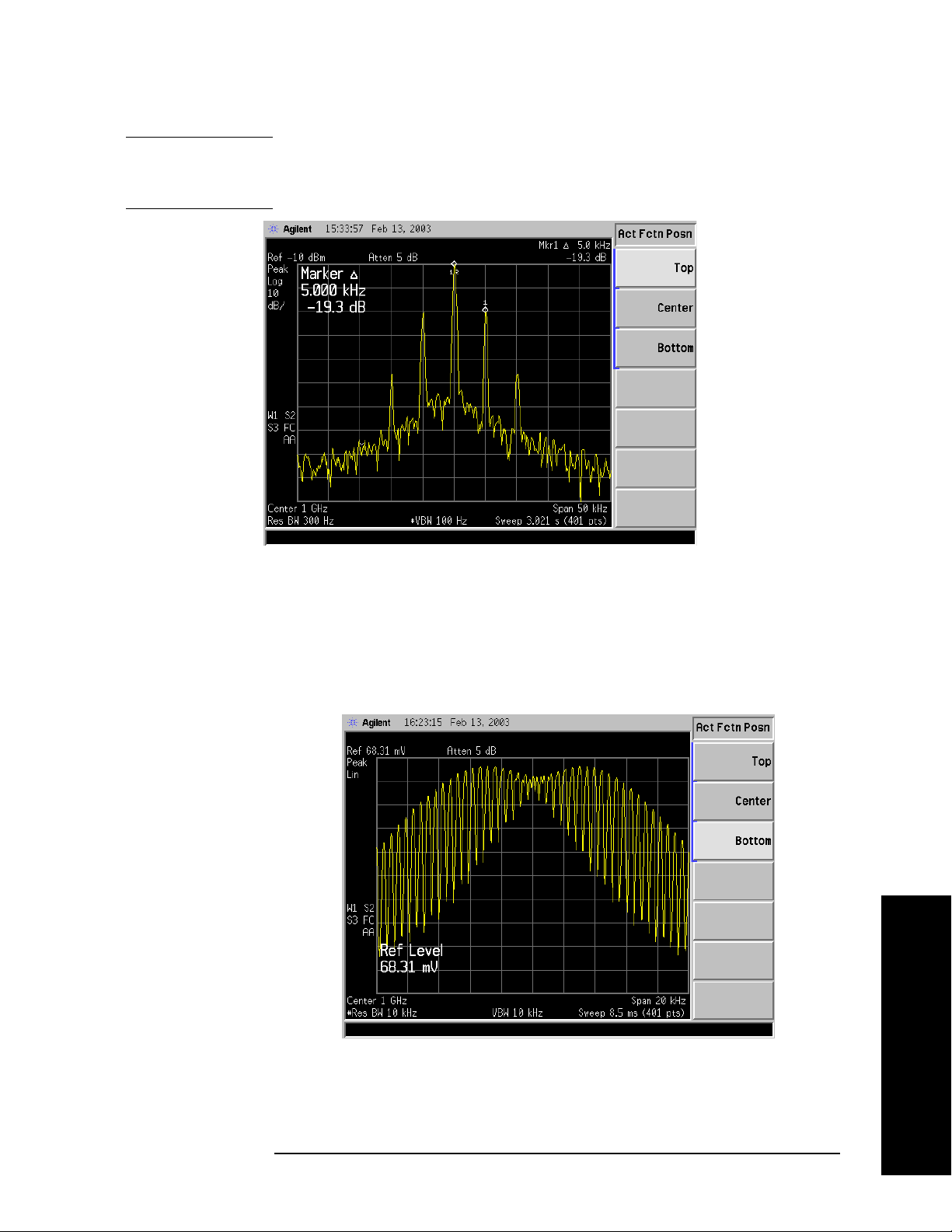
Front-Panel Key Reference
Display
NOTE Do not select Active Fctn Position, Top when performing limit or margin
tests as the pass/fail messages for these functions will be overwritten by
the active function information.
Center
Bottom
Key Access:
Display, Active Fctn Position
Displays the active function in the center-left side of the
display.
Key Access:
Display, Active Fctn Position
Displays the active function in the bottom-left corner of
the display
Front-Panel Key Reference
Title
Key Access:
Display, Active Fctn Position
Accesses the following Title menu keys which allows you to change or
Chapter 2 79

Front-Panel Key Reference
Display
clear a title on your display.
Key Access:
Change Title Allows you to write a title across the top of the display.
Display
The marker readout may interfere with the last
characters. The markers can be turned off by pressing
Marker, More, Marker All Off. Pressing Change Title
accesses the Alpha Editor Menus that contain available
characters and symbols.
NOTE Pressing ESC before exiting the Alpha Editor menus will retain the
previous title.
The display title will remain until either
Change Title is
pressed again, or a trace is recalled that was previously
saved with a title. A display title can also be cleared by
Clear Title
using the clear function. Press
Key Access:
Display, Title
Allows you to clear a title from the front-panel display.
Display, Title, Clear Title.
Once cleared, the title cannot be retrieved.
Preferences
Key Access:
Accesses a menu of the following display functions which allow you to
Display, Title
turn the graticule and annotation on or off.
Key Access:
Graticule
On Off
Annotation
On Off
Turns the display graticule on and off.
Turns the screen annotation on or off, however, menu
Display
Key Access:
Display, Preferences
key annotation will remain on the screen. The screen
annotation may not be required for prints or during
remote operation.
Key Access:
Display, Preferences
Front-Panel Key Reference
80 Chapter 2

Front-Panel Key Reference
Enter
Enter
Terminates and enters into the analyzer a numerical value that has
been entered from the front panel using the numeric keypad. (For most
applications, it is better to use the units menu keys.)
When using the
filename entries. When entering titles (
Enter key is used to terminate title entries.
File key menus, the Enter key is used to terminate
Display, Title, Change Title), the
Chapter 2 81
Front-Panel Key Reference

Front-Panel Key Reference
ESC
ESC
Use the escape key to exit any function without modifying current
parameters. Pressing the
• Clear any numeric entry that you have begun to enter and cancels
the active function (see the section on display annotation, active
function area, and other display features in the Getting Started
Guide for your instrument).
• Clear any title entry that you have begun to enter and cause the title
to revert to the previous name.
• Clear input or output overloads.
• Clear error messages from the status line along the bottom of the
display.
• Clear peak threshold from the display (turn it off) if the peak
threshold line is on.
ESC key will:
• Cancels a print, if one is in progress.
Front-Panel Key Reference
82 Chapter 2

Front-Panel Key Reference
File
Accesses the menu keys used to view, save, load, and manage data on a
floppy disk or the internal analyzer drive. Refer to the Getting Started
Guide for your instrument for more information on file menu functions.
Catalog Displays all directories and files located on the selected drive,
depending upon the preferences set under the
defined below.
Typ e and Sort keys
File
Key Access:
Type
Allows you to select all types or one type of file(s) for
File
viewing.
Key Access:
Displays all files located on the selected
All
File, Catalog
drive.
Key Access:
Setup
Displays all setup files (.SET) in the
File, Catalog, Type
selected directory. Setups are a
complete set of instrument parameters
including traces, states, limits, and
corrections.
Key Access:
State
Displays all state files (.STA) in the
File, Catalog, Type
selected directory. State files contain
most instrument settings.
Key Access:
Trac e
Displays all trace files (.TRC and .CSV)
File, Catalog, Type
in the selected directory.
Key Access:
Limits
Displays all limits files (.LIM) in the
File, Catalog, Type
selected directory.
File, Catalog, Type
Screen
Key Access:
Displays all screen (.GIF and .WMF)
files in the selected directory.
Corrections
Key Access:
Displays all correction files (.ANT,
File, Catalog, Type
.CBL, .OTH, .AMP) in the selected
directory.
Key Access:
Chapter 2 83
File, Catalog, Type, More
Front-Panel Key Reference

Front-Panel Key Reference
File
Measurement Results Displays all measurement results
files in the selected directory.
Measurement results files are saved in
.CSV format (for importing into
spreadsheets).
Save
Key Access:
Sort
Accesses the Sort menu keys that allow you to sort your
File, Catalog, Type, More
files according to a selected file attribute.The selections
include,
Order Up Down. Order (Up) allows you to sort files in
ascending order (for instance, A,B,C).
By Date, By Name, By Extension, By Size, and
Order (Down)
allows you to sort files in descending order (for
instance, C,B,A).
Key Access:
Dir Up
Allows you to move up one directory level. If at the top
Dir Up moves to the drive level, displaying the
level,
File, Catalog
available disk drives.
Dir Select
Key Access:
Accesses the highlighted directory on your display.
Key Access:
File, Catalog
File, Catalog
Accesses menu keys that allow you to save analyzer setups, states,
traces, limits, corrections and screen data to a floppy (A:) drive or
internal flash (C:) drive.
Front-Panel Key Reference
NOTE If you intend to save trace files for use with a personal computer, save
them as .CSV (comma separated values). However, files fomatted in
this way cannot be loaded back into the analyzer.
NOTE Never remove the floppy disk during a save operation. To do so could
corrupt all data on the floppy disk.
Key Access:
Save Now
File
Executes the save function. When the save is complete,
the message XXXXXX file saved (where XXXXXX is
the filename) will appear in the status line on your
display.
Note that once you have used the
keys to setup and save a file, the
perform an immediate
Save Now of your file in the same
File, Save, Save Now
Save hardkey will
format and to the same location.
Key Access:
File, Save
84 Chapter 2

Front-Panel Key Reference
File
NOTE If the Path: field above the directory box is empty when pressing Save
Now
, the status line will display the error message: Unable to save
file, invalid path. In this case, please select a drive.
Type Allows you to select the type of data you want to save.
Setup Displays all previously saved setup
files and detects the current setup
parameters in preparation to save them
in a file for retrieval at a future date.
Setup files include all instrument
settings including traces, states, limits,
and corrections.
NOTE When viewing a floppy disc with saved Setup files (filename.set) on a
personal computer, notice there are also many similarly named files
with extensions like .s01, .s02, etc. Do not delete these files as they are
necessary to allow complete restoration of originally saved Setup.
Key Access:
State
Displays all previously saved state files
File, Save, Type
and detects the current state
parameters in preparation to save them
in a file for retrieval at a future date.
State files include all instrument
settings but not traces, limits, and
corrections. (This is the default setting
when power is applied to the analyzer.)
Key Access:
Trac e
Displays all previously saved trace files
File, Save, Type
(.TRC) and detects the current trace in
preparation to save it in a file for
retrieval at a future date. A trace can
be saved individually or as a group of
traces. It can also be saved in .CSV
(comma separated values) format (for
importing into spreadsheets) or in .TRC
format, accompanied by the analyzer
state (for later recalling into the
analyzer). (Note that CSV formatted
data cannot be reloaded into the
analyzer and TRC formatted data
cannot be loaded into most personal
computer programs.) Refer to the
Format key description.
Front-Panel Key Reference
Key Access:
Chapter 2 85
File, Save, Type

Front-Panel Key Reference
File
Limits Displays all previously saved limits
files and detects the current limits in
preparation to save them in a file for
retrieval at a future date. Limits
provide data sets to determine whether
a trace has exceeded preset
specifications. Limit sets can hold up to
200 points and can only be saved
individually. Refer to the
File, Source
key description.
File, Save, Type
Screen
Key Access:
Displays all previously saved screen
files and captures the current screen
displayed in preparation to save it in a
file for retrieval at a future date.
Screen files can be saved in any of the
following formats: Bitmap, Metafile,
Reverse Bitmap, and Reverse Metafile.
Refer to the
Key Access:
NOTE Screen files saved in WMF format can only be loaded into Microsoft®
Format key description.
File, Save, Type
applications such as Microsoft Word.
NOTE The screen saved is that which was displayed before pressing File. For
this reason, the screens seen while in the file menus cannot be saved.
Corrections Displays all previously saved correction
files and detects the current corrections
in preparation to save them in a file for
retrieval at a future date. Corrections
provide a way to adjust the trace
display for preset gain factors (such as
for cable loss). A correction set may
hold up to 200 points. Pressing
Corrections activates the Source key.
Refer to the
Source key description.
1
Front-Panel Key Reference
Key Access:
Measurement Results
Displays all previously saved
measurement results files and detects
the current measurement results in
preparation to save them in a file for
retrieval at a future date.
1. Microsoft® is a U.S. registered trademark of Microsoft Corporation.
86 Chapter 2
File, Save, Type, More

Front-Panel Key Reference
File
Measurement results files are saved in
.CSV format (for importing into
spreadsheets).
Format
Source
Key Access:
File, Save, Type, More
When Type is set to Trace, Format allows you to save a
trace accompanied by the analyzer state. The
CSV
format is readable by a spreadsheet on your PC, but
cannot be loaded back into the analyzer. The TRC
format cannot be loaded into a PC, but can be loaded
back into the analyzer. TRC files include the state of
the analyzer and restore all settings when loaded.
When
between bitmap and metafile formats.
Typ e is set to Screen, Format allows you to choose
Bitmap saves the
screen image in Graphics Interchange Format (GIF)
and
Metafile saves the screen image in Windows
Metafile Format (WMF).
Metafile
turn black backgrounds to white and yellow
Reverse Bitmap and Reverse
traces to green so they can be printed visibly and with
less use of black ink. Screen images cannot be loaded
back into the analyzer.
Key Access:
File, Save
When Type is set to Trace, Source allows you to save
trace
1, 2, or 3 along with state. Saving trace All saves
all traces in a single .trc file, along with the state.
When
Antenna, Cable, Other and User menu keys, which allow
Typ e is set to Corrections, Source accesses the
you to select the type of correction to be saved.
When
and
Typ e is set to Limits, Source accesses the Limit 1
Limit 2 menu keys. Limit 1 and Limit 2 provide data
sets to determine whether a trace has exceeded preset
specifications. Limit sets can hold up to 200 points and
can only be saved individually.
Key Access:
Name
Accesses the Alpha Editor and allows you to enter a
File, Save
filename. The external keyboard can also be used to
enter a filename while the alpha editor is accessed.
Key Access:
NOTE Only capital letters (A-Z) and digits (0-9) may appear in file names (8
File, Save
characters, maximum). Additionally, file names include a 3 character
extension which is automatically set by the instrument.
Front-Panel Key Reference
Chapter 2 87

Front-Panel Key Reference
File
Dir Up Allows you to move up one directory level. If at the top
Dir Up moves to the drive level, displaying the
level,
available disk drives.
Load
Dir Select
Key Access:
Accesses the highlighted directory on your display.
Key Access:
File, Save
File, Save
Accesses menu keys that allow you to load analyzer setups, states,
traces, limits and corrections into the analyzer from a floppy (A:) drive
or internal flash (C:) drive.
Key Access:
Load Now
File
Executes the load function. When the load is complete,
the message XXXXXX file loaded (where XXXXXX is
the filename) will appear in the status line on your
display.
Key Access:
Type
Allows you to select the type of file you want to load.
Setup Displays all setup files you may wish to
File, Load
load (.SET). Setup files include a
complete set of instrument parameters
including traces, states, limits, and
corrections. Loading a setup restores
the analyzer (as closely as possible) to
all previous instrument settings at the
time of the save.
Front-Panel Key Reference
Key Access:
State
Displays all state files you may wish to
File, Load, Type
load (.STA). Loading a state restores
most settings to the previously saved
values.
Key Access:
Trac e
Displays all trace files (.TRC) you may
File, Load, Type
wish to load. Traces can be loaded
individually or as a group. When a
trace is loaded, the state that existed
when that trace was saved is loaded
along with the trace. Also, the loaded
trace is placed in view mode.
Key Access:
88 Chapter 2
File, Load, Type

Front-Panel Key Reference
NOTE If you wish to compare two saved traces, place traces in view mode
before saving them. This prevents the trace from being rewritten based
on a state change from subsequent loads.
Limits Displays all limits files you may wish to
load to determine whether a trace has
exceeded preset specifications (.LIM).
Limit sets can hold up to 200 points.
Limits can only be loaded individually.
File
Key Access:
NOTE When loading Limits files, be sure you have selected the appropriate
X Axis Units: frequency or time (
Display, Limits, X Axis Units). If you are
File, Load, Type
in time X-Axis Units, and you load frequency limits, all current limit
line data will be erased and the analyzer will switch to frequency units.
The reverse of the this situation also holds true.
Corrections Displays all corrections files you may
wish to load (.CBL, .ANT, .OTH, .AMP).
Corrections provide a way to adjust the
trace display for preset gain factors
(such as for cable loss). A correction set
may hold up to 200 points.
Key Access:
Measurement Results
Displays all previously saved
File, Load, Type, More
measurement results files you may
wish to load. Measurement results files
are saved in .CSV format (for importing
into spreadsheets).
Key Access:
File, Load, Type, More
Sort
Accesses the Sort menu key.
Sort accesses a menu of keys that allow you to view
your saved files according to a selected file attribute.
The selections include,
By Size, and Order Up Down. Order (Up) allows you to
By Date, By Name, By Extension,
view files in ascending order (for instance, A,B,C).
Order (Down) allows you to view files in descending
order (for instance, C,B,A).
Destination
Key Access:
When Type is set to Trace, Destination allows you to
direct your data to
is for all three traces (for instance,
File, Load
Trace 1, Trace 2, or Trace 3. If the data
Source was All when
they were saved), the data will be returned to the
original trace registers.
Chapter 2 89
Front-Panel Key Reference

Front-Panel Key Reference
File
When Typ e is set to Limits, Destination allows you to
direct your data to
Limit 1 or Limit 2.
Delete
Key Access:
Dir Up
Allows you to move up one directory level. If at the top
Dir Up moves to the drive level, displaying the
level,
File, Load
available disk drives.
File, Load
Dir Select
Key Access:
Accesses the highlighted directory on your display. If
[..] is highlighted, this key acts in the same manner as
Dir Up.
Key Access:
File, Load
Allows you to delete files and directories.
Key Access:
Delete Now
File
Executes the delete function. If a directory is selected to
be deleted, the message WARNING: You are about to
delete the contents of directory XXXXXX (where
XXXXXX is the full path and directory name) will
appear on your display. After a successful delete, the
message XXXXXX file deleted (where XXXXXX is the
filename) will appear in the status line on your display.
Key Access:
Type
Allows you to select the type of file you want to delete.
Key Access:
All
Displays all files you may wish to
File, Delete
File, Delete
delete.
Key Access:
Setup
Displays all setup files you may wish to
File, Delete, Type
delete (.SET). A Setup file is a complete
state of instrument parameters
including traces, states, limits and
corrections.
Key Access:
State
Displays all state files you may wish to
File, Delete, Type
delete (.STA).
Key Access:
Trac e
Displays all trace files you may wish to
File, Delete, Type
delete (.TRC and .CSV).
Front-Panel Key Reference
Key Access:
90 Chapter 2
File, Delete, Type

Front-Panel Key Reference
File
Limits Displays all limits files you may wish to
delete (.LIM).
File, Delete, Type
Screen
Key Access:
Displays all screen files you may wish
to delete (.GIF and .WMF).
File, Delete, Type
Corrections
Key Access:
Displays all corrections files you may
wish to delete (.CBL, .ANT, .OTH,
.AMP).
Key Access:
Measurement Results
Displays all previously saved
File, Delete, Type, More
measurement results files you may
wish to delete. Measurement results
files are saved in (.CSV) format (for
importing into spreadsheets).
Key Access:
Sort
Sort accesses a menu of keys that allow you view the
File, Delete, Type, More
files you wish to delete, according to a selected file
attribute. The selections include,
Extension
, By Size, and Order Up Down. Order (Up) allows
By Date, By Name, By
you to view files you may wish to delete in ascending
order (for instance, A,B,C).
Order (Down) allows you to
view files you may wish to delete in descending order
(for instance, C,B,A).
Copy
File, Delete
Dir Up
Key Access:
Allows you to move up one directory level. If at the top
level,
Dir Up moves to the drive level, displaying the
available disk drives.
File, Delete
Dir Select
Key Access:
Accesses the highlighted directory on your display. If
[..] is highlighted, this key acts in the same manner as
Dir Up.
Key Access:
File, Delete
Allows you to copy files from one directory to another or to one or more
mass storage devices.
Key Access:
Copy Now
File
. Executes the copy function. If the copy is successful, the
message xxxxx file copied (where xxxxx is the
filename) will appear on the display.
Key Access:
File, Copy
Front-Panel Key Reference
Chapter 2 91

Front-Panel Key Reference
File
Type. Allows you to select the type of file you want to copy.
Key Access:
All
. Displays all files you may wish to copy.
File, Copy
Key Access:
File, Copy, Typ e
Setup. Displays all setup (.SET) files you may
wish to copy. A Setup file is a complete
state of instrument parameters
including traces, states, limits and
corrections.
NOTE When using a personal computer to copy Setup files, ensure the
similarly named files with extensions like .s01, .so2, etc. are also copied.
These files are necessary to allow complete restoration of originally
saved Setup.
Key Access:
State
. Displays all state (.STA) files you may
File, Copy, Typ e
wish to copy.
Key Access:
Trac e
. Displays all trace (.TRC and .CSV) files
File, Copy, Typ e
you may wish to copy.
Front-Panel Key Reference
Key Access:
Limits
. Displays all limit (.LIM) files you may
File, Copy, Typ e
wish to rename.
File, Copy, Typ e
Screen
Key Access:
. Displays all screen (.GIF and .WMF)
files you may wish to rename.
File, Copy, Typ e
Corrections
Key Access:
. Displays all corrections (.CBL, .ANT,
.OTH, .AMP) files you may wish to
rename.
Key Access:
Measurement Results
. Displays all previously saved
File, Copy, Typ e, More
measurement results files you may
wish to delete. Measurement results
files are saved in (.CSV) format (for
importing into spreadsheets).
Key Access:
Sort
. Sort accesses a menu of keys that allow you to view the
File, Copy, Type, More
files you wish to copy according to a selected file
92 Chapter 2

Front-Panel Key Reference
File
attribute. The selection includes, By Date, By Name, By
Extension
, By Size, and Order Up Down. Order (Up) allows
you to view files you may wish to copy in ascending
order (for instance, A,B,C).
Order (Down) allows you to
view files you may wish to copy in descending order (for
instance, C,B,A).
Rename
Key Access:
Dir
From To
. Allows you to select the source and destination
directories for your copy on one or more drives.
Key Access:
Dir Up
. Allows you to move up one directory level. If at the top
Dir Up moves to the drive level, displaying the
level,
available disk drives.
Key Access:
Dir Select
. Accesses the highlighted directory on your display.
Key Access:
Allows you to rename a file.
Key Access:
Rename Now
File
Executes the rename function. When the rename is
complete, the message XXXXXX file renamed to
YYYYYY (where XXXXXX and YYYYYY are the
filenames) will appear in the status line on your
display.
File, Copy
File, Copy
File, Copy
File, Copy
Key Access:
Allows you to select the type of file you want to rename.
Type
Key Access:
All
Displays all files you may wish to
File, Rename
File, Rename
rename.
Key Access:
Setup
Displays all setup (.SET) files you may
File, Rename, Type
wish to rename. A Setup file is a
complete state of instrument
parameters including traces, states,
limits and corrections.
Key Access:
State
Displays all state (.STA) files you may
File, Rename, Type
wish to rename.
Key Access:
Chapter 2 93
File, Rename, Type
Front-Panel Key Reference

Front-Panel Key Reference
File
Trac e Displays all trace (.TRC and .CSV) files
you may wish to rename.
Key Access:
Limits
Displays all limit (.LIM) files you may
File, Rename, Type
wish to rename.
File, Rename, Type
Screen
Key Access:
Displays all screen (.GIF and .WMF)
files you may wish to rename.
Corrections
Key Access:
Displays all corrections (.CBL, .ANT,
File, Rename, Type
.OTH, .AMP) files you may wish to
rename.
Key Access:
Measurement Results
Displays all previously saved
File, Rename, Type, More
measurement results files you may
wish to rename. Measurement results
files are saved in (.CSV) format (for
importing into spreadsheets).
Key Access:
Sort accesses a menu of keys that allow you to view the
Sort
File, Rename, Type, More
files you wish to rename according to a selected file
attribute. The selections include,
Extension
, By Size, and Order Up Down. Order (UP) allows
By Date, By Name, By
you to view files you may wish to rename in ascending
order (for instance, A,B,C).
Order (Down) allows you to
view files you may wish to rename in descending order
(for instance, C,B,A).
Front-Panel Key Reference
Key Access:
Name
Accesses the Alpha Editor and allows you to enter a
File, Rename
filename. The external keyboard can also be used to
enter a filename while the alpha editor is accessed.
Complete your entry by pressing
NOTE Only capital letters (A-Z) and digits (0-9) may appear in file names
Return or Enter.
(8 characters, maximum). Additionally, file names include a 3 character
extension which is automatically set by the instrument.
Key Access:
Dir Up
Allows you to move up one directory level. If at the top
Dir Up moves to the drive level, displaying the
level,
File, Rename
available disk drives.
Key Access:
94 Chapter 2
File, Rename

Front-Panel Key Reference
Dir Select Accesses the highlighted directory on your display.
File
File, Rename
Create Dir
Key Access:
Allows you to create subdirectories.
Key Access:
Create Dir
Now
Executes the create directory function. When the
File, More
directory has been created, the message Directory
XXXXXX created (where XXXXXX is the directory
name) will appear in the status line on your display.
Key Access:
Name
Accesses the Alpha Editor and allows you to enter a
File, More, Create Dir
filename. The external keyboard can also be used to
enter a filename while the alpha editor is accessed.
Complete your entry by pressing
Key Access:
NOTE Only capital letters (A-Z) and digits (0-9) may appear in file names
File, More, Create Dir
Return or Enter.
(8 characters, maximum). Additionally, file names include a 3 digit
extension which is automatically set by the instrument.
Format
Dir Up Allows you to move up one directory level. If at the top
Dir Up moves to the drive level, displaying the
level,
available disk drives.
Dir Select
Key Access:
Accesses the highlighted directory on your display.
Key Access:
File, More, Create Dir
File, More, Create Dir
Formats a double-density floppy disk to 1.44 MB format. 720 kB disks
are not supported.
Key Access:
Format Now
File, More
Executes the format function. After pressing
Format Now, the following message will appear on the
display: WARNING: You are about to destroy ALL
data on volume A: Press Format Now again to
proceed or any other key to abort. During the
formatting, Formatting Disk will appear on the display.
Once formatted, Volume A: formatted will appear in the
status line on the display.
Front-Panel Key Reference
Chapter 2 95

Front-Panel Key Reference
File
NOTE When using a personal computer to manipulate Setup files
(filename.set) saved to a floppy, ensure the similarly named files with
extensions like .s01, .s02, etc. are handled in a like manner. For
example, if you rename of the .set file, you must rename all the .s0x
files, as well. These files are necessary to allow complete restoration of
the originally saved Setup.
Key Access:
File, More, Format
Front-Panel Key Reference
96 Chapter 2

Front-Panel Key Reference
Freq Count
Freq Count
Activates the Marker Normal function if there are no markers, and then
turns the marker count function on.
Marker Count
On Off
Marker Count (On) turns on the marker counter. If no marker is active
before
of the display. Press
Press
Marker Count (On) is pressed, a marker is activated at the center
Marker Count (Off) to turn the marker counter off.
Resolution (Man) to change the marker counter resolution to an
uncoupled value.
NOTE Marker Count frequency readings are not affected by the frequency
offset function.
An asterisk (*) may appear in the upper-right area of the display along
with the message Cntr 1 (the number in the message depends on the
active marker). The ratio of the resolution bandwidth to span must be
greater than 0.002 for the marker count function to work properly.
Marker Count: Widen Res BW appears on the display if the bandwidth
to span ratio is less than 0.002. Widen RES BW indicates that the
resolution bandwidth must be increased or the span decreased.
Freq Count
Resolution
Auto Man
Key Access:
Allows the resolution of the marker counter to be selected manually or
auto-coupled. The marker counter has a resolution range of 1 Hz to
100 kHz. The available resolution values are 1 Hz, 10 Hz, 100 Hz,
1 kHz, 10 kHz, and 100 kHz. The resolution can be changed by using
the step keys or by entering the resolution using the numeric keypad or
knob. The marker counter resolution can be auto coupled to the span by
pressing
Resolution (Auto).
Key Access:
Chapter 2 97
Freq Count
Front-Panel Key Reference

Front-Panel Key Reference
FREQUENCY Channel
FREQUENCY Channel
Activates the center frequency function, and accesses the menu of
frequency functions. The center frequency, or start and stop frequency
values appear below the graticule on the display.
Although the analyzer allows entry of frequencies greater than the
specified frequency range, using frequencies greater than the frequency
range of the analyzer is not recommended
NOTE When changing both the center frequency and the span, change the
frequency first since the span can be limited by the frequency value.
CAUTION When operating in dc coupled mode, take care to protect the input
mixer by limiting the input level to 0 Vdc and +30 dBm.
Center Freq Activates the center frequency function (when Scale Type is set to Lin)
which allows you to set the horizontal center of the display to a specific
frequency. When
center frequency function which allows you to move the average of the
start and stop frequencies. In this scale type the center frequency value
will not necessarily represent the horizontal center of the display.
Scale Type is set to Log, Center Freq activates the
Start Freq
Stop Freq
CF Step
Auto Man
Key Access:
FREQUENCY Channel
Sets the frequency at the left side of the graticule. The left and right
sides of the graticule correspond to the start and stop frequencies.
When these frequencies are activated, their values are displayed below
the graticule in place of center frequency and span.
Key Access:
FREQUENCY Channel
Sets the frequency at the right side of the graticule. The left and right
sides of the graticule correspond to the start and stop frequencies.
When these frequencies are activated, their values are displayed below
the graticule in place of center frequency and span.
Key Access:
FREQUENCY Channel
Changes the step size for the center frequency function. Once a step
size has been selected and the center frequency function is activated,
the step keys change center frequency by the step-size value. The step
size function is useful for finding harmonics and sidebands beyond the
current frequency span of the analyzer. When auto-coupled, the center
frequency step size is set to one division (10 percent of the span).
Key Access:
FREQUENCY Channel
Front-Panel Key Reference
98 Chapter 2

Front-Panel Key Reference
FREQUENCY Channel
Freq Offset Allows you to input a frequency offset value that is added to the
frequency readout of the marker, to account for frequency conversions
external to the analyzer. Offset entries are added to all frequency
readouts including marker, start frequency, and stop frequency. Offsets
may only be entered using the numeric keypad. Offsets are not added to
the span or frequency count readouts. Entering an offset does not affect
the trace display. When a frequency offset is entered, its value appears
on the bottom of the display. To eliminate an offset, perform a
Preset, or press Freq Offset, 0, Hz.
Factory
When a frequency offset is entered, its value appears on the bottom of
the display (as opposed to reference level offsets, which appear on the
left side of the display). To eliminate an offset, press
Enter. Pressing Preset also sets the offset to zero.
NOTE This function is not available when FREQUENCY, Scale Type (Log) is
Freq Offset, 0, and
selected.
NOTE Frequency, Scale Type (Log) is not available when utilizing the frequency
offset function.
FREQUENCY Channel
Signal Track
On Off
Key Access:
Moves the signal that is nearest to the active marker to the center of
the display and keeps the signal there. ST appears in the lower-left
corner of the display. An (*) may appear in the upper-right corner of the
display while the analyzer is verifying that it has the correct signal.
Pressing
Marker, More, Marker All Off turns off the signal track function.
Signal Track (Off); Preset (with Preset Type set to Factory); or
When signal track is on and the span is reduced, an automatic zoom is
performed and the span is reduced in steps so that the signal remains
at the center of the display. If the span is zero, signal track cannot be
activated.
Key Access:
NOTE If no marker is active, pressing Signal Track (On) will activate a marker,
FREQUENCY Channel
perform a peak search, and center the marker on the display.
NOTE Switching to zero span sets Signal Track (Off).
NOTE FREQUENCY, Scale Type (Log) and Segmented (On) are not available
when Signal Track (On) is selected.
Front-Panel Key Reference
Chapter 2 99

Front-Panel Key Reference
FREQUENCY Channel
Scale Type
Log Lin
Agilent ESA-E Series only (E4401B, E4402B, E4404B, E4405B and
E4407B). Scales the horizontal (x-axis or frequency) graticule divisions
logarithmically when
Scale Type (Log) is selected. When Scale Type (Lin)
is selected, the horizontal divisions are linearly scaled.
Scale Type (Log), the number of sweep points is limited to a multiple
In
of the number of sweep segments. For example, if you select 308 points
when 3 segments are required to create a logarithmic display, the
points will be set at 306 points. The span determines the minimum
number of sweep points. Pressing
Factory) sets Scale Type to Lin.
NOTE Sweep time is auto-coupled when Scale Type (Log) is selected.
NOTE Marker Span Pair, Frequency Offset, Input Mixer (Ext), Segmented (On),
Signal Track (On), and Demod View (On), are not available when Scale
Type (Log) is selected.
NOTE FREQUENCY, Scale Type (Log) is not available when Frequency Offset,
Segmented (On), Input Mixer (Ext), Zero Span, Signal Track (On) is selected.
Key Access:
FREQUENCY Channel
Preset (when Preset Type is set to
Front-Panel Key Reference
100 Chapter 2
 Loading...