

Page 1

User’s Guide
Agilent Technologies
ESA-E Series Spectrum Analyzers
Option 227
Cable TV Measurement Personality
This manual applies to Cable TV Measurement Personality version A.02.00.
This manual provides documentation for the following instruments:
ESA-E Series
E4401B (9 kHz - 1.5 GHz)
E4402B (9 kHz - 3.0 GHz)
E4404B (9 kHz - 6.7 GHz)
E4405B (9 kHz - 13.2 GHz)
E4407B (9 kHz - 26.5 GHz)
Manufacturing Part Number: E4401-90228
Printed in USA
July 2000
© Copyright 2000 Agilent Technologies
Page 2

Notice
The information contained in this document is subject to change without notice.
Agilent Technologies makes no warranty of any kind with regard to this material,
including but not limited to, the implied warranties of merchantability and fitness
for a particular purpose. Agilent Technologies shall not be liable for errors
contained herein or for inc idental or con sequentia l damages in conn ection with the
furnishing, performance, or use of this material.
Agilent Technologies assumes no responsibility for the use or reliability of its
software on equipment that is not furnished by
Agilent Technologies.
Restricted Rights Legend
Use, duplication, or disclosure by the U.S. Government is subj ec t to restrictions as
set forth in subparagra ph (c)(1)(ii) of the Righ t s in Technical Data and Co mputer
Software clause at DFARS 252.227-7013 for DOD agencies, and subparagraphs
(c)(1) and (c)( 2) of t he Commercia l Computer Software Res tricte d Rights clause at
FAR 52.227-19 for other agencies.
Agilent Technologies
1400 Fountaingrove Parkway
Santa Rosa, CA 95403, U.S.A.
ii
Page 3

Warranty Information
IMPORTANT Certification
Agilent Technologies certifies that this product met its published specifications at
the time of shipment from the factory. Agilent Technologies further certifies that
its calibration mea surements are tracea ble to the United St ates Nati onal Instit ute of
Standards and Technology (NIST, formerly NBS), to the extent allowed by the
Institute’s calibration facility, and to the calibration facil it ie s of other International
Standards Organization members.
NOTE The actual warran ty on your instrument dep ends on the date it was ordered as well
as whether or not any warranty options were purchased at that time. To determine
the exact warranty on your instrument, contact the nearest Agilent Technologies
sales or service office with the model and serial number of your instrument. See
the list of sales and service offices in this document.
This Agilent Technologies instrument produc t is warranted against de fects in
material and workmanship for the warranty period. During the warranty period,
Agilent Technologies will, at its option, either repair or replace products which
prove to be defective.
If the warranty covers repair or service to be performed at the Buyer’s facility, then
the service or repair will be performed at the Buyer’s facility at no charge within
Agilent Technologies service travel areas. Outside Agilent Technologies service
travel areas, warranty service will be performed at Buyer’s facility only upon
Agilent Technologies prior agreement, and Buyer shall pay Agilent Technologies
round-trip trave l expenses. In al l other areas , products must be r eturned to a ser vice
facility designated by Agilent Technologies.
If the product is to be retu rned t o Agilent Technologies for service or repa ir , it must
be returned to a service facility designated by Agilent Technologies. Buyer shall
prepay shipping charges to Agilent Technologies and Agilent Technologies shall
pay shipping charges to return the product to Buyer. However, Buyer shall pay all
shipping charges, duties, and taxes for products returned to Agilent Technologies
from another country.
Agilent Technologies warrants that its software and firmware designated by
Agilent Technologies for use with an instrument will execute its programming
instructions when p roperl y ins tall ed on t hat instr ument. Agi lent Technologies does
not warrant that the operation of the instrument, or software, or firmware will be
uninterrupted or error-free.
iii
Page 4

Limitation of Warranty . The fore going warra nty shall not apply to defects r esulti ng
from improper or inadequate maintenance by Buyer, Buyer-supplied software or
interfacing, unauthorized modification or misuse, operation outside of the
environmental specifications for the product, or improper site preparation or
maintenance.
NO OTHER WARRANTY IS EXPRESSED OR IMPLIED. AGILENT
TECHNOLOGIES SPECIFICALLY DISCLAIMS THE IMPLIED
WARRANTIES OF MERCHANTABILITY AND FITNESS FOR A
PARTICULAR PURPOSE.
EXCLUSIVE REMEDIES
THE REMEDIES PROVIDED HEREIN ARE BUYER’S SOLE AND
EXCLUSIVE REMEDIES. AGILENT TECHNOLOGIES SHALL NOT BE
LIABLE FOR ANY DIRECT, INDIRECT, SPECIA L, INCIDENTAL, OR
CONSEQUENTIAL DAMAGES, WHETHER BASED ON CONTRACT, TORT,
OR ANY OTHER LEGAL THEORY.
iv
Page 5

Getting Started
What You Will Find in This Chapter . . . . . . . . . . . . . . . . . . . . . . . . . . . . . . . . . . . . . . . . . . . . . . . . . . . . . 1-2
Introduction. . . . . . . . . . . . . . . . . . . . . . . . . . . . . . . . . . . . . . . . . . . . . . . . . . . . . . . . . . . . . . . . . . . . . . . . . 1-3
Checking the Shipment. . . . . . . . . . . . . . . . . . . . . . . . . . . . . . . . . . . . . . . . . . . . . . . . . . . . . . . . . . . . . . . . 1-4
Supported Spectrum Analyzer Requirements . . . . . . . . . . . . . . . . . . . . . . . . . . . . . . . . . . . . . . . . . . . . . . 1-5
Licensing the Cable TV Measurement Personality . . . . . . . . . . . . . . . . . . . . . . . . . . . . . . . . . . . . . . . . . . 1-6
Installing the Cable TV Measurement Personality. . . . . . . . . . . . . . . . . . . . . . . . . . . . . . . . . . . . . . . . . . . 1-7
Uninstalling the Cable TV Measurement Personality . . . . . . . . . . . . . . . . . . . . . . . . . . . . . . . . . . . . . . . . 1-8
Measurements
What You Will Find in This Chapter . . . . . . . . . . . . . . . . . . . . . . . . . . . . . . . . . . . . . . . . . . . . . . . . . . . . . 2-2
Making Channel Measurements . . . . . . . . . . . . . . . . . . . . . . . . . . . . . . . . . . . . . . . . . . . . . . . . . . . . . . . . 2-3
Step 1. Configure the test system . . . . . . . . . . . . . . . . . . . . . . . . . . . . . . . . . . . . . . . . . . . . . . . . . . . . . . 2-4
Configuration Procedures . . . . . . . . . . . . . . . . . . . . . . . . . . . . . . . . . . . . . . . . . . . . . . . . . . . . . . . . . . 2-4
User Defined Channel. . . . . . . . . . . . . . . . . . . . . . . . . . . . . . . . . . . . . . . . . . . . . . . . . . . . . . . . . . . . . 2-6
Measurement Bandwidth. . . . . . . . . . . . . . . . . . . . . . . . . . . . . . . . . . . . . . . . . . . . . . . . . . . . . . . . . . . 2-6
External Preamplifier . . . . . . . . . . . . . . . . . . . . . . . . . . . . . . . . . . . . . . . . . . . . . . . . . . . . . . . . . . . . . 2-7
External Pad Compensation . . . . . . . . . . . . . . . . . . . . . . . . . . . . . . . . . . . . . . . . . . . . . . . . . . . . . . . . 2-7
Step 2. Connect the signal to the analyzer . . . . . . . . . . . . . . . . . . . . . . . . . . . . . . . . . . . . . . . . . . . . . . . 2-8
Step 3. Make the measurements . . . . . . . . . . . . . . . . . . . . . . . . . . . . . . . . . . . . . . . . . . . . . . . . . . . . . . . 2-9
Optimizing the Dynamic Range . . . . . . . . . . . . . . . . . . . . . . . . . . . . . . . . . . . . . . . . . . . . . . . . . . . . 2-14
Optimizing the Total Power at the Input. . . . . . . . . . . . . . . . . . . . . . . . . . . . . . . . . . . . . . . . . . . . . . 2-14
Access the TV Picture Mode (Optional). . . . . . . . . . . . . . . . . . . . . . . . . . . . . . . . . . . . . . . . . . . . . . 2-23
Modifying the Channel Plan . . . . . . . . . . . . . . . . . . . . . . . . . . . . . . . . . . . . . . . . . . . . . . . . . . . . . . . . . 2-24
If You Have a Problem
What You Will Find in This Chapter . . . . . . . . . . . . . . . . . . . . . . . . . . . . . . . . . . . . . . . . . . . . . . . . . . . . . 3-2
Error Messages . . . . . . . . . . . . . . . . . . . . . . . . . . . . . . . . . . . . . . . . . . . . . . . . . . . . . . . . . . . . . . . . . . . . . 3-3
If the Test Results Are Not What You Expected . . . . . . . . . . . . . . . . . . . . . . . . . . . . . . . . . . . . . . . . . . . . 3-4
How to Contact Agilent Technologies . . . . . . . . . . . . . . . . . . . . . . . . . . . . . . . . . . . . . . . . . . . . . . . . . . . . 3-5
Channel Measurements Menu Map
What You Will Find in This Chapter . . . . . . . . . . . . . . . . . . . . . . . . . . . . . . . . . . . . . . . . . . . . . . . . . . . . . 4-2
Channel Measurements Menu Map . . . . . . . . . . . . . . . . . . . . . . . . . . . . . . . . . . . . . . . . . . . . . . . . . . . . . . 4-3
SCPI Commands
SCPI Commands . . . . . . . . . . . . . . . . . . . . . . . . . . . . . . . . . . . . . . . . . . . . . . . . . . . . . . . . . . . . . . . . . . . . 5-2
Test Descriptions
What You Will Find in This Chapter . . . . . . . . . . . . . . . . . . . . . . . . . . . . . . . . . . . . . . . . . . . . . . . . . . . . . 6-2
Visual Carrier Level and Visual-to-Aural Level and Frequency Difference Test Description. . . . . . . . . . 6-3
Carrier-to-Noise Ratio Test Description . . . . . . . . . . . . . . . . . . . . . . . . . . . . . . . . . . . . . . . . . . . . . . . . . . 6-6
Composite Second Order (CSO) Test Description . . . . . . . . . . . . . . . . . . . . . . . . . . . . . . . . . . . . . . . . . 6-11
Composite Triple Beat (CTB) Test Description . . . . . . . . . . . . . . . . . . . . . . . . . . . . . . . . . . . . . . . . . . . 6-14
Hum Test Description . . . . . . . . . . . . . . . . . . . . . . . . . . . . . . . . . . . . . . . . . . . . . . . . . . . . . . . . . . . . . . . 6-16
Depth of Modulation Test Description . . . . . . . . . . . . . . . . . . . . . . . . . . . . . . . . . . . . . . . . . . . . . . . . . . . 6-19
v
Page 6

Specifications and Test Aids
What You Will Find in This Chapter . . . . . . . . . . . . . . . . . . . . . . . . . . . . . . . . . . . . . . . . . . . . . . . . . . . . . .7-2
Cable TV Measurement Specifications and Characteristics . . . . . . . . . . . . . . . . . . . . . . . . . . . . . . . . . . . .7-3
C/N, CSO, and CTB Measurements . . . . . . . . . . . . . . . . . . . . . . . . . . . . . . . . . . . . . . . . . . . . . . . . . . . .7-6
Channel Identification Plans . . . . . . . . . . . . . . . . . . . . . . . . . . . . . . . . . . . . . . . . . . . . . . . . . . . . . . . . . . . .7-8
Safety and Regulatory Information
Introduction . . . . . . . . . . . . . . . . . . . . . . . . . . . . . . . . . . . . . . . . . . . . . . . . . . . . . . . . . . . . . . . . . . . . . . . . .8-2
Cleaning Instructions . . . . . . . . . . . . . . . . . . . . . . . . . . . . . . . . . . . . . . . . . . . . . . . . . . . . . . . . . . . . . . . .8-2
Shipping Instructions . . . . . . . . . . . . . . . . . . . . . . . . . . . . . . . . . . . . . . . . . . . . . . . . . . . . . . . . . . . . . . . .8-2
Before Applying Power . . . . . . . . . . . . . . . . . . . . . . . . . . . . . . . . . . . . . . . . . . . . . . . . . . . . . . . . . . . . . .8-2
Safety Information . . . . . . . . . . . . . . . . . . . . . . . . . . . . . . . . . . . . . . . . . . . . . . . . . . . . . . . . . . . . . . . . . . . .8-3
Warnings. . . . . . . . . . . . . . . . . . . . . . . . . . . . . . . . . . . . . . . . . . . . . . . . . . . . . . . . . . . . . . . . . . . . . . . . . .8-3
Cautions . . . . . . . . . . . . . . . . . . . . . . . . . . . . . . . . . . . . . . . . . . . . . . . . . . . . . . . . . . . . . . . . . . . . . . . . . .8-4
Instrument Markings. . . . . . . . . . . . . . . . . . . . . . . . . . . . . . . . . . . . . . . . . . . . . . . . . . . . . . . . . . . . . . . . .8-5
Safety, Earth, Ground . . . . . . . . . . . . . . . . . . . . . . . . . . . . . . . . . . . . . . . . . . . . . . . . . . . . . . . . . . . . . . . .8-5
Agilent Technologies Sales and Service Offices . . . . . . . . . . . . . . . . . . . . . . . . . . . . . . . . . . . . . . . . . . .8-6
vi
Page 7

1 Getting Started
Page 8

Getting Started
What You Will Find in This Chapter
What You Will Find in This Chapter
This chapter provi des step-by- step procedur es for setti ng up a spectru m analyzer t o
perform cable TV measurements. This chapter contains the following sections:
• Introduction
• Checking the Shipment
• Supported Spectrum Analyzer Requirements
• Licensing the Cable TV Measurement Personality
• Installing the Cable TV Measurement Personality
• Uninstalling the Cable TV Measurement Personality
1-2 Cable TV Measurement Personality User’s Guide
Page 9

Getting Started
Introduction
Introduction
With the Agilent Technologies ESA E-Series with Option 227 your spectrum
analyzer is both a full-featured spectrum analyzer and a cable TV service and
installation analyzer.
The cable TV mode is used to perform channel-by-channel measurements. This
allows execution of a single measurement on a single channel.
Cable TV Measurement Personality User’s Guide 1-3
Page 10

Getting Started
Checking the Shipment
Checking the Shipment
Verify that the following items are in this shipment. Contact your nearest Agilent
Technologies sales or service office. (Refer to the Agilent Technologies Sales and
Service Offices” on page 8-6) if any items are missing or damaged.
Table 1-1 ESA Option 227 Materials Supplied
Description Agilent Technologies
Part Number
ESA Option 227
Cable TV Measurement Personality User’s
Guide
Personality (Version A.02.00)
(provided on 3.5-inch floppy disks)
E4401-90228 1
E4401-10006 1
Quantity
1-4 Cable TV Measurement Personality User’s Guide
Page 11

Getting Started
Supported Spectrum Analyzer Requirements
Supported Spectrum Analyzer Requirements
The ESA Option 227 is designed to operate with 75 Ω and 50 Ω ESA-E Series
spectrum analyzers.
Cable TV Measurement Personality User’s Guide 1-5
Page 12

Getting Started
Licensing the Cable TV Measurement Personality
Licensing the Cab le TV Measureme nt Personality
In order to start using the features of the Cable TV Measurement Personality, it
must be licensed. To license your Cable TV Measurement Personality:
NOTE If you ordered the Cable TV Measurement Personality with a new spectrum
analyzer proceed to st ep 5 of the Installing the Cable TV Measurement
Personality” on page 1-7, and verify that the program is already installed.
1. Turn the spectrum analyzer on. After the analyzer has completed its power on
sequence. Press
System, Licensing.
2. Press
Option and use the alpha editor keys to enter the name of the option . For
the Cable TV Measurement Personality the option name is 227.
3. Press
Return to go back to the licensing menu and select License Key . Use
the numeric keypad and the alpha editor keys to enter the appropr ia te licensing
key for your spectrum analyzer.
4. Press
Return to return to the licen sing menu and p ress Activate to license your
installed personality.
1-6 Cable TV Measurement Personality User’s Guide
Page 13

Getting Started
Installing the Cable TV Measurement Personality
Installing the Cable TV Measurement Personality
The Cable TV Measurement Personality is supplied on a floppy di sk. To install the
program into your spectrum analyzer:
1. Press
System, Personalities.
The screen will list the personalities currently installed in your analyzer.
2. Insert the Cable TV Measurement Personality floppy disk into the analyzer
disk drive and press
now or verify the disk. Press
3. After the installation has been completed press
Install. The installer utility will ask if you wish to install
Install Now to install the personality.
Exit Installer to go back to the
analyzer mode and cycle the power to the analyzer.
4. To verify that the Cable TV Measurement Personality has been properly
installed, press
MEASURE and ch eck that the last key is lab eled CATV.
Cable TV Measurement Personality User’s Guide 1-7
Page 14

Getting Started
Uninstalling the Cable TV Measurement Personality
Uninstalling the Cable TV Measur ement Personality
To uninstall the Cable TV Measurement Personality from the spectrum analyzer
follow these steps:
1. Press
2. Press
System, Personalities.
Uninstall and using the up
Meas. Pers
3. Press
Uninstall Now. The analyzer will ask you to confirm the command by
pressing
Uninstall Now again. After t he confir mation the Ca ble TV per sonality
will be uninstalled.
.” field.
and down ⇓ arrows select the “
⇑
Cable TV
1-8 Cable TV Measurement Personality User’s Guide
Page 15

2 Measurements
Page 16

Measurements
What You Will Find in This Chapter
What You Will Find in This Chapter
This chapter contain s informatio n describing how to make cable TV measurements
and how to modify channel plans.
The tests are listed on the following pages along with the keys that activate them.
2-2 Cable TV Measurement Personality User’s Guide
Page 17

Measurements
Making Channel Measurements
Making Channel Measurements
This section explains the steps that are necessary to make channel measurements.
The steps are as follows:
1. Configure the test system
2. Connect the signal to the analyzer
3. Make the measurements
NOTE Early versions (before personality version A.01) required that each measurement
must be turned off prior to changing the channel. Press
measurement.
To speed up the testing process the newer personality version allows changing the
channels after the measurement has produced a result.
Meas Off to turn off the
Table 2-1 Channel Measurements
To activate Press
Carrier Level and Frequency
Carrier to Noise C/N Ratio
Composite Second Order/Composite Triple Beat CSO/CTB
Hum Hum
Depth of Modulation Depth Mod
Carrier Lvl
Cable TV Measurement Personality User’s Guide 2-3
Page 18

Measurements
Making Channel Measurements
Step 1. Configure the test system
Use MEASURE, CATV, Setup, TVSTD to set up TV standard, channel tu ning, a
user defined channel, and an external preamplifier.
NOTE An additional way to set the TV standa rd i s prov ide d if TV Trigger (Option B7B)
is installed. This method is by pressing keys
two methods of setting the TV standard work independently of each other.
However, wh en a CATV measurement is started, wha tever standard i s set under t he
Trig menu is changed to match the standard that was set under MEASURE.
Therefore , it is important that
MEASURE, CATV, Setup, TVSTD is used to set the
TV standard before starting CATV measurements.
NOTE The information is stored in nonvolatile analyzer memory. This means that the
analyzer retains the information, even when the power is turned off, until you
access the setup menu again and change it.
Configuration Procedures
Trig, TV Trig Setup, Standard. The
1. Press
NOTE The default TV standard is set to NTSC-M.
2. Press
MEASURE, CATV, Setup.
TVSTD and choose the appropriate TV standard: NTSC-M, NTSC-J,
PAL-M, PAL-B/G, PAL-D/K, or PAL-I (the default TV standard is set to
NTSC-M).
3. Press
NOTE The channel plan that i s shown in th e menu will de pend on which TV standard wa s
Plan and the appropriate channel plan key.
enabled in step 2. For example, if the TV standard NTSC-M was enabl ed i n st ep 2
then the channel plan menu would display the following selections: STD, AIR,
IRC, HRC, and T, but would not show the CBL, VHF, or other channel plans.
The default configuration menu allows you to select one of the following
channel formats:
• NTSC-M and PAL-M channel plans
— STD Standard Cable
— AIR Broadcast Channels
— HRC HRC Cable
— IRC IRC Cable
— T Upstream Channels
2-4 Cable TV Measurement Personality User’s Guide
Page 19

Making Channel Measurements
• NTSC-J
— CBL Japan Standard Cable
— AIR Japan Broadcast channels
•PAL-B/G
— HRC HRC Cable
— VHF VHF Channels
— UHF UHF Channels
— S S Channels PAL-B/G Standard
— S-Cable S Channels PAL-B/G Cable
— CENELEC CENELEC Channels
•PAL-D/K
— DS China Broadcast Channels
Measurements
— Z China Standard Cable
•PAL-I
— HRC HRC Cable
— VHF VHF Channels
— UHF UHV Channels
Cable TV Measurement Personality User’s Guide 2-5
Page 20

Measurements
Making Channel Measurements
User Defined Channel
The following keys in the set up menu allow you to de fine the cente r frequenc y and
span for a user def ine d chan nel. This channe l is t hen ac cesse d b y sel ectin g c hannel
0 (zero). Refer to Figure 2-1.
Chan 0 Freq Channel 0 center frequency
•
Chan 0 Span Channel 0 span
•
One convenient use for Channel 0 is for testing at 44 MHz IF.
Figure 2-1 Channel Tuning Menu
Measurement Bandwidth
Measuremen t Bandwidth carrier to noise, bandwidth default is
4 MHz for NTSC-M, NTSC-J and PAL-M.
NOTE Bandwidth default for PAL-I, PAL-B/G and PAL-D/K is 5 MHz.
2-6 Cable TV Measurement Personality User’s Guide
Page 21

Measurements
Making Channel Measurements
External Preamplifier
1. Using an external preamplifier, for analyzers without an internal preamplifier:
An external p reamplifier ma y be required for the carrier-to-noise test. Se e
Chapter 6, “Test Descriptions,” which contains more i nformat ion abou t when a
preamplifier is required for the carrier-to-noise test. The carrier-to-noise test
calculates the noise contribution of the external preamplifier, and reports the
correction on the
More Info screen of the carrier-to-noise test. If an external
preamplifier is used, enter the preamplifier gain and noise figure using
Ext Amp Gain and Ext Amp NZ Fig in the Setup menu.
NOTE Inaccurate values used for Ext Amp Gain and Ext Amp NZ Fig can result in
significant measurement errors. Use Agilent 85905A preamplifier with measured
data for accurate results.
NOTE If an external preamplifier is not used, Ext Amp Gain and Ext Amp NZ Fig values
must be set to zero or carrier-to-noise ratio calculation errors may occur.
2. Connect the cable TV signal as described in “Step 2. Connect the signal to the
analyzer” on page 2-8.
External Pad Compensation
EXT P AD Yes No key can be used to compensate for the amplitude loss caused
1.
by using a 50 Ω to 75 Ω external matching pad. (A 50 Ω to 75 Ω external
matching pad is used to match the signal from a 75Ω impedance system to a
spectrum analyzer with a 50 Ω impedance input.) The external pad function
compensates for the 5.8 dB amplitude loss of the external pad by setting the
spectrum analyzer's reference level offset to 5.8 dB.
2. If you are using a spectrum analyzer with 50 Ω input impedance but are not
using an external matching pad, the cable TV analyzer mode will compensate
for most of the impedance mis mat ch, but ampl itude measure ments ca n have up
to ±0.2 dB error caused by the uncompensated mismatch over the frequency
range.
This function is set to
No when the ESA Option 227 personality is loaded into
analyzer memory.
The setting of the external pad function is stored in nonvolatile spectrum
analyzer memory. Storing the setting in nonvolatile memory means that once
the external pad function is set to
Yes, it will remain set to Yes until you
change the setting or delete the ESA Option 227 personality program from
analyzer memory.
MEASURE, CATV, Setup to access Ext Pad Yes No.
Press
Cable TV Measurement Personality User’s Guide 2-7
Page 22

Measurements
Making Channel Measurements
Step 2. Connect the signal to the analyzer
CAUTION To prevent the analyzer input circuits from being damaged, the total power at the
analyzer input must be less than +75 dBmV.
To optimize the analyzer input mixer for the best measurement range without
being overloaded, the tota l power at the analyzer input mixe r must be l ess t han +47
dBmV for C/N and less than +37 dBm for CSO/CTB. Total power greater than
these will add anal yzer atte nuation. The se values a re 10dB great er tha n the Agilen t
8591C Spectrum Analyzer, resulting in more measurement dynamic range using
the Agilent ESA analyzer. Compare the accuracy and characteristics graphs of
Figure 7-1 on page 7-7 with those of the Agilent 8591C analyzer.
For systems with unequal carrier levels (system tilt), the total power must be
calculated by summing the individual carriers. The
accounts for system tilt.
Total Power key function
You can measure the input power by pressing
Power
. The total power is displayed at the bottom of the screen.
MEASURE, CATV, Setup, Total
Total power at the input mixer can be reduced by increasing input attenuation.
Amplitude, Attenuation and make the adjustment. The analyzer retains a
Press
manually selected attenuation until you either select a new value, or reset the
analyzer power-on default conditions. For all tests provided by the cable TV
measurement personality, the analyzer automatically selects the attenuator setting
to meet the above requirements.
2-8 Cable TV Measurement Personality User’s Guide
Page 23

Measurements
Making Channel Measurements
Step 3. Make the measurements
Most measurements updat e the result at the end of a sweep or at the en d of multiple
sweeps. Refer to each measurement type.
NOTE
Carrier Level and
Frequency Test
1. If you accidentally use the wrong key sequence, re-enter the channel. Press
MEASURE, CATV, Channel, enter the channel number, and press Enter.
2. If you want to set the analyzer to the power-on default conditions after using
the cable TV functions, you can either cycle the power or press
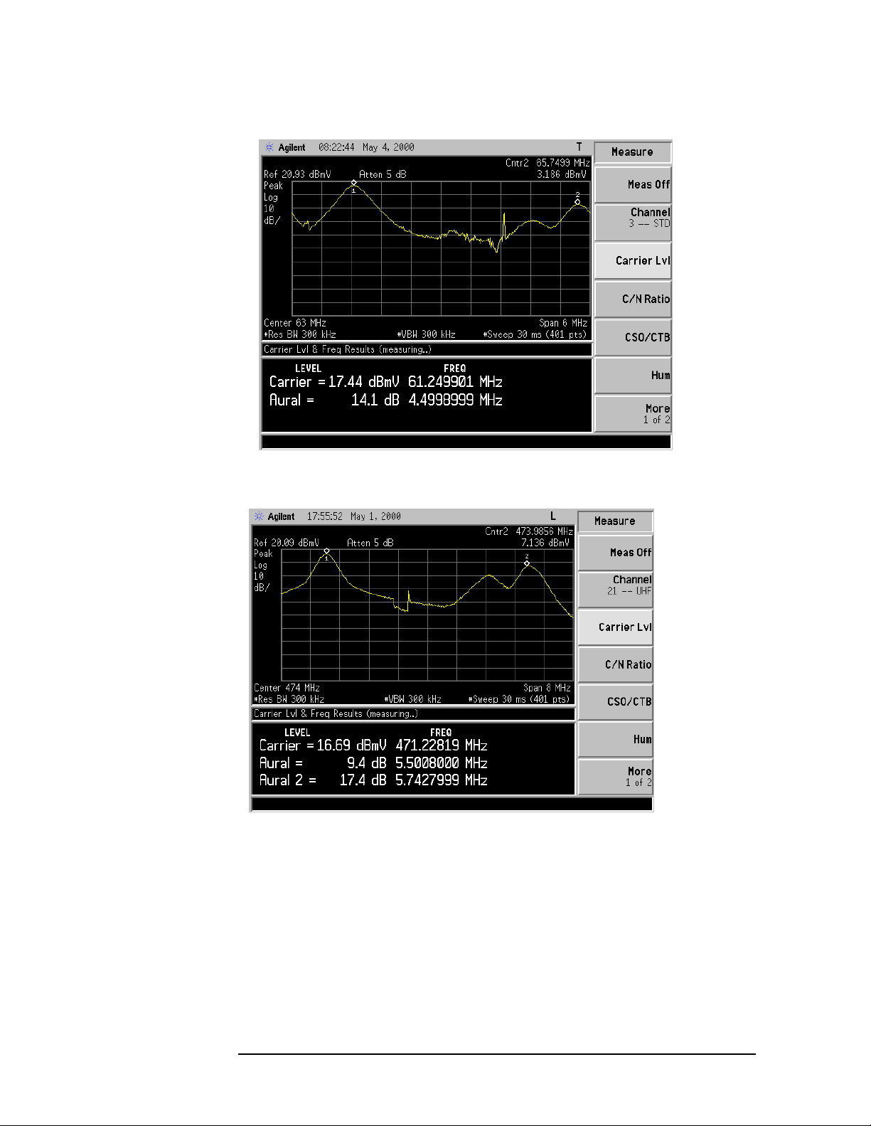
1. Select a channel and press
MEASURE, CATV, Carrier Lvl. The peak visual
Preset.
carrier level and visual-to-aural carrier difference appear on the screen. See
Figure 2-2.
Frequencies and power ratios for both sound carriers are displayed when the
following TV standards (and associated sound carriers) are used:
• PAL-I with NICAM
•PAL-B/G
• PAL-B/G with NICAM
See Figure 2-3 on page 2-10 and Figure 2-4 on page 2-11.
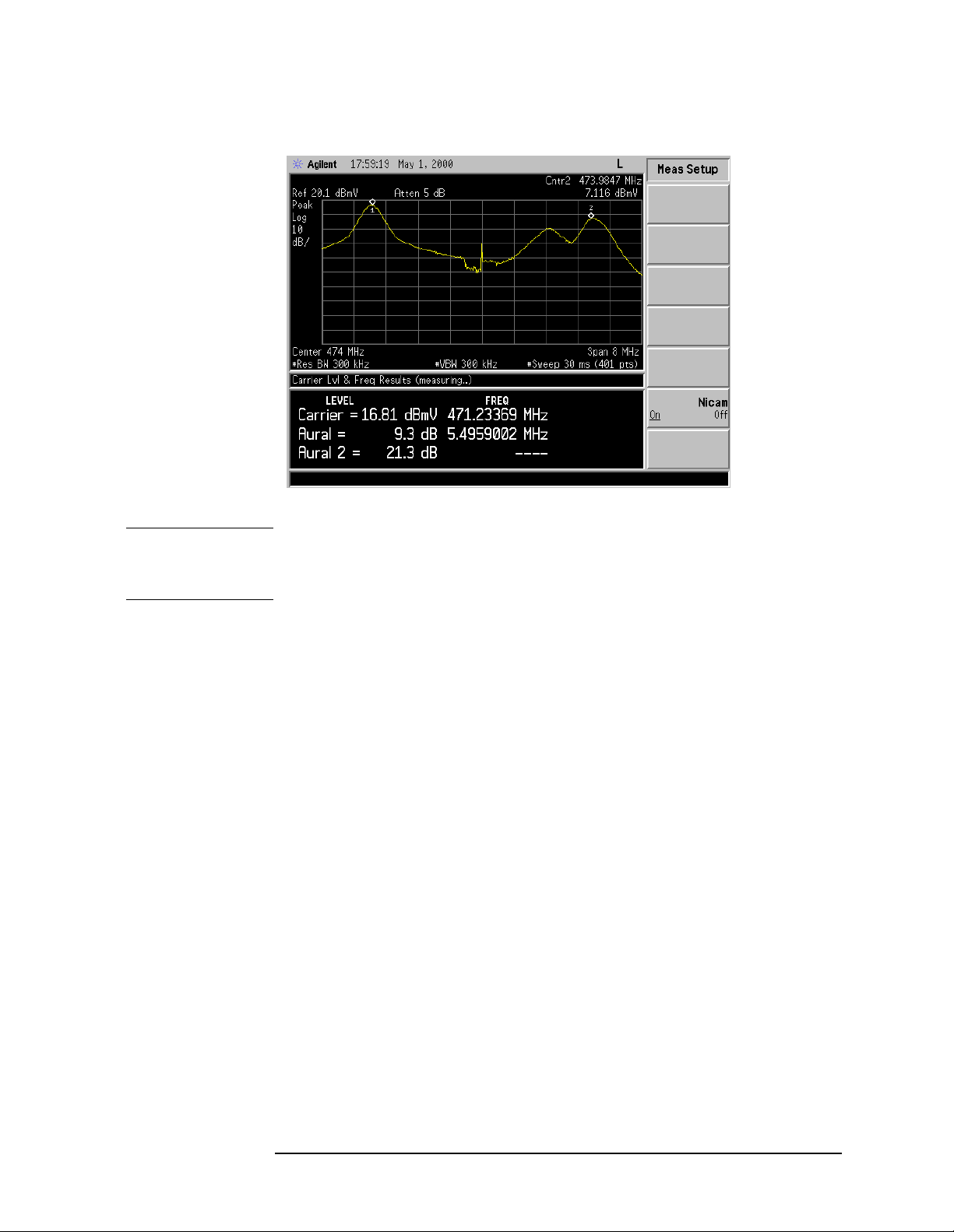
2. If it is available, press
Nicam On Off (On). A true RMS power measurement is
made across the NICAM band and the visual-to-sound power ratios are
displayed.
NOTE The Nicam key is availabl e onl y whe n PAL-I or PAL-B/G has been selected in the
TVSTD menu. It is not an indication that a NICAM carrier is present in the
channel.
3. Press
Cable TV Measurement Personality User’s Guide 2-9
MEASURE, CATV, Meas Off to exit th e test.
Meas Control to control single sweep, pause, and restart.
Press
Page 24
Measurements
Making Channel Measurements
Figure 2-2 Carrier Level Measurement (NTSC-M)
Figure 2-3 Carrier Level Measurement (PAL-B/G with Nicam Off)
2-10 Cable TV Measurement Personality User’s Guide
Page 25
Making Channel Measurements
Figure 2-4 Carrier Level Measurement (PAL-B/G with Nicam On)
Measurements
NOTE For best results, the carrier-to-noise ratio (in 4 MHz BW or 5 MHz BW) of the
system should be 40 dB or greater, and the measured signal level should be 30 dB
or greater above the displayed noise during the test.
For sync suppressed scrambled signals the results will be inconsistent. To stabilize
the result press
the max hold function then
View/Trace, Max Hold. To exit the test, press Clear Write to exit
MEASURE, CATV, Measure Off. To speed level
measurements on a number of channels, a new channel can be tuned during the
measurement. Press
Channel, enter the channel number, and press Enter or use the
up arrow ⇑ or down arrow ⇓ to move to adjacent channels.
Carrier-to-Noise
Test
1. Select a channel, then press
2. Perform th e following steps:
MEASURE, CATV, C/N Ratio.
a. The marker defaults to the minimum system noise near the lower channel
boundary. Wait for the analyzer to return an answer.
b. Remove the carrier and modulation to perform the carrier-to-noise test.
c. Press
Marker, then using the knob, move the marker to the desired position
in the indic ated “FCC MEASUREMENT RANGE.” Refer to Figure 2-5 on
page 2-12.
Cable TV Measurement Personality User’s Guide 2-11
Page 26

Measurements
Making Channel Measurements
NOTE “FCC Measurement Range” is onl y applied fo r NTSC-M, NTSC-J and PAL-M TV
standards . The messag e “Measurement Range” will be di sp layed for the other TV
standards. See Figure 2-6 on page 2-13.
The FCC measurement range ba ndwi dth is defined as 4 MHz. Mea sur ement r ange
bandwidths other than the FCC measurement range bandwidth are defined as 5
MHz.
Change the measurement bandwidth by pressing
Meas BW, and enter the desired bandwidth.
d. Use averaging to stabilize the result. Press
MEASURE, CATV, Setup,
BW/Avg, Averaging On. Check
that the average type is set to video.
The carrier-to-noise test compares the system noise level at the analyzer input
to that of the analyzer itself. If these levels are within 3 dB of each other, the
analyzer will display the message “
See More Info
” (under
the measurement result. If the difference is less than 2.2 dB, the message is in
inverse video. Refer to Chapter 6, “Test Descriptions,” for more detailed
information about the carrier-to-noise measurement.
3. Press
More Info to display the carrier-to-noise calculation. See Figure 2-7 on
page 2-13. To exit the test, press
MEASURE, CATV, Meas Off.
Figure 2-5 Carrier-to-Noise — FCC Measurement Range (NTSC-M)
Meas Setup) next to
2-12 Cable TV Measurement Personality User’s Guide
Page 27

Figure 2-6 Carrier-to-Noise (PAL-B/G)
Measurements
Making Channel Measurements
Figure 2-7 Carrier-to-Noise, More Information (NTSC-M)
Cable TV Measurement Personality User’s Guide 2-13
Page 28

Measurements
Making Channel Measurements
Carrier to Noise
with an External
Preamplifier
Preamplifier noise is calculated and corrected when an external preamplifier is
used. External preamplifier gain and noise figure are used for this calculation.
External preamplifier keys
Ext Amp Gain and Ext Amp NZ Fig are used only for
this purpose. Refer to the notes under “External Preamplifier” on page 2-7 for
proper usage.
1. When using a tunable bandpass filter, first peak the filter using the
Carrier Lvl key. Press Meas Off, C/N Ratio. Place the marker to measure the
carrier- to-noise clos e enough to the car rier to minimi ze any roll-of f ef fect of the
bandpass filter.
2. Carrier-to-noise measurement accuracy is degraded as the cable TV system
noise approaches the analyzer noise. This is reflected in the magnitude of the
analyzer noise correction value.
3. Note the analyzer noise correction value by pressing
More Info.
• if less than 0.5 dB, then C/N accuracy is ±1 dB
• if equal to 0.5 dB, then C/N accuracy is ±1.25 dB
• if equal to 3 dB, then C/N accuracy is ±2 dB
• if equal to 7 dB, then C/N accuracy is ±3.5 dB
• if greater than 7 dB, C/N is out of measurement range
4. The analyzer input a ttenuator se ts the noise f loor of th e analyzer. The attenuator
is set to not overload the first mixer. For carrier to no ise, the attenu ator switch
point from 0 to 5 dB is at +47 dBmV to tal power at the input. (This r ange is 10
dB more than the Agilent 8591C spectrum analyzer.)
Optimizing the Dynamic Range
Limiting the number of carriers input to the analyzer allows the measurement
routine to select a lower attenuator value, providing the analyzer a lower noise
floor . This ca n be done with individ ual channel filters, a high pass filt er , a low pass
filter or an adjustable bandpass filter.
When the attenuator switches to the next higher value, the noise floor raises 5 dB
which degrades the signal to noise ratio by 5 dB. For C/N, the attenuator switches
from 0 dB to 5 dB at +47 dBmV. Keeping the total power just below that will
obtain the best signal to noise ratio.
A 1 dB (or smalle r than 5 dB) step attenuator used in conjuncti on with a filter will
provide the best coverage of signal range for optimizing the total power at the
input.
Optimizing the Total Power at the Input
If the analyzer correc tion value dict ates that it is nece ssary to optimize the analyzer
noise floor for a particular configuration, press
Power
.
MEASURE, CATV, Setup, Total
2-14 Cable TV Measurement Personality User’s Guide
Page 29

Measurements
Making Channel Measurements
For carrier to nois e, th e attenuator switch point from 0 dB to 5 dB attenuatio n is at
+47 dBmV. The attenuator switch point from 5 dB to
10 dB is at +52 dBmV and increments proportionately with each 5 dB step in
attenuation.
Measuring C/N with modulation on is limited to a maximum range of 55 dB.
Measuring C/N with modulation off within 2 MHz of the carrier is limited to a
maximum range of 55 dB. For a higher maximum C/N range, measure noise
farther than 2 MHz from the carrier when th e carrier is on , o r turn the carrier off.
Refer to the g raphs shown in
Figure 7-1 on page 7-7.
Composite
Second
Order/Composite
Triple Beat
1. Select a channel, then press
2. Perform th e following steps:
a. The marker de faults to the lower beat.
MEASURE, CATV, CSO/CTB.
(CSO/CTB) Test
b. To perform the carrier-to-beats test remove the carrier and modulation by
turning the modulator off.
NOTE The carrier-to-b eats test for NTSC-M, NTSC-J, and PAL-M is done according to
FCC requirements.
c. Using the knob, move the marker to the desired beat. See
Figure 2-8 on page 2-17. Note that if the mar ker i s not a ct ive , yo u wi ll need
to press the
NOTE For NTSC-J, please refer to Figure 2-9 on page 2-17 and for PAL-B/G, PAL-D/K
Marker key. Alternatively, press Meas Setup, Next Beat.
and PAL-I refer to Figure 2-10 on page 2-18.
d. Turn averaging on by pressing
averaging type is video. Press
BW/Avg, Average On. Check that the
Return to get back to the cable measure
menu.
3. Move the marker to the nex t beat by pressing
Next Beat. Using the front-panel
knob will also allow measuring beats other than at the standard CSO/CTB
offsets.
The results of the measurement are displayed at the bottom of the analyzer
display.
4. Press
Meas Setup, and then Atten Down or Atten Up, to make the attenuator
check for analyzer gene rate d beats when no t usin g a bandpa ss fil ter. Switch the
attenuator up and down to check for changes in the beat level.
If the beat level does not change, then the beat is not generated in the analyzer.
If the beat level changes with attenuator changes, then raise the attenuator
setting until the bea t l ev el no longer changes. The di spl ayed noise may prevent
accurate measurement results.
Cable TV Measurement Personality User’s Guide 2-15
Page 30

Measurements
Making Channel Measurements
NOTE The measurement automatically sets the attenuator to prevent analyzer generated
beats upon entering the test. The analyzer switches from 0 dB attenuation to 5 dB
attenuation at +37 dBmV of total power at the input.
5. Remove the carrier, or press
or below the carri er (i f an op en sp ace ex ists) . Eac h time
CTB Up or CTB Down to measure the CTB ab ove
CTB Up is pressed, the
marker is automatically positioned at the next CTB above the carrier (+6 MHz
increments). Each time
CTB Down is pressed, the marker is automatically
positioned at the next CTB below the carrier (−6 MHz increments).
NOTE ±6 MHz increments only are applied for NTSC-M, NTSC-J and PAL-M TV
standards. PAL-B/G, P AL-D/K and PAL-I will have ±7 MHz or ±8 MHz, ±8 MHz
and ±8 MHz increments respectively.
6. Press the
test, press
NOTE When using a tunable bandpass filter, first peak the filter using Carrier Lvl. Make
More Info key to display the carrier-to-beat calculation. To exit the
MEASURE, CATV, Meas Off.
sure the filter band width is suf fici ent that the beats are not rolled off. See Table 2-2
below .
Table 2-2 Boundary Beats
TV Standard Lowest
Beat (MHz)
Highest
Beat (MHz)
NTSC-M –1.25 +1.25
NTSC-J –1.25 +4.00
PA L-M –1.25 +1.25
PAL-B/G
(7 MHz span)
PAL-B/G
(8 MHz span)
PAL-D/K CTB +6.25
PAL-I CTB +6.25
CTB +5.25
CTB +6.25
2-16 Cable TV Measurement Personality User’s Guide
Page 31

Figure 2-8 CSO/CTB Measurement (NTSC-M)
Measurements
Making Channel Measurements
Figure 2-9 CSO/CTB Measurement (NTSC-J)
Cable TV Measurement Personality User’s Guide 2-17
Page 32

Measurements
Making Channel Measurements
Figure 2-10 CSO/CTB Measurement (PAL-B/G)
NOTE See the graphs, Figu re 7-1 on page 7-7, for measurement range versus visual
carrier level.
Hum Test
1. Select a channel or tune directly to the carrier to be measured. Make sure that
the desired carri er is the highest on t he screen by adjus ting the ce nter fre quency
or span as needed. Turn off modulation (optional), then press
CATV, Hum. See Figure 2-11 on page 2-19.
NOTE After pressing Hum, the analyzer determines if video modula tion is presen t or not.
MEASURE,
If the video modulation is on and the test result is greater than 3 percent, an
additional message appears advising the operator to retest using a CW signal only.
2. Press
More Info to perform a single sweep and a Fast Fourier Transform (FF T)
to separate power line related components. See Figure 2-12 on page 2-20.
60 Hz, 120 Hz, 180 Hz, and 240 Hz are displayed. This is intended to be used
as a troubleshooting aid. A relatively high 60 Hz level implies inadequate
grounding or stray power util ity neutral cur rents. A relativel y high 120 Hz level
implies poor filtering of a full-wave rectifier in a power supply.
NOTE For TV standards PAL-B/G, PAL-D/K and PAL-I, 50 Hz, 100 Hz, 15 0 Hz and 200
Hz are displayed instead. These values also are intended to be used as a
troubleshooting aid. A high 50 Hz level inplies inadequate grounding or stray
power utility neutral currents. A high 100 Hz level inplies poor filtering of a
full-wave rectifier in a power supply. See Figure 2-13 on page 2-20.
3. To exit the test, press
2-18 Cable TV Measurement Personality User’s Guide
MEASURE, CATV, Meas Off.
Page 33

Measurements
Making Channel Measurements
NOTE For best result s, the c hannel carrier -t o-noise ratio s hould be 4 0 dB or greater (in a 4
MHz or 5 MHz noise bandwidth).
The hum test requires a carrier wave. It cannot give meaningful results when a
channel uses sync suppression scrambling (unless the measurement is made at the
subscriber terminal output of a descrambler). Measuring hum with video
modulation present requires that all sync tips have the same general level in order
to measure their variation.
Invalid information is given when the hu m test is perf ormed on channe ls with sync
suppression scrambling.
Figure 2-11 Hum Measurement (NTSC-M)
Cable TV Measurement Personality User’s Guide 2-19
Page 34

Measurements
Making Channel Measurements
Figure 2-12 Hum, More Information (NTSC-M)
Figure 2-13 HUM, More Information (PAL-B/G)
Depth of Video
Modulation Test
1. Select the channel and press
updated every 50 analyzer sweeps (approximately every 6 seconds). Refer to
Measure, CATV, Depth Mod. The result is
Figure 2-14.
2. To exit the test, press
3. Press the
2-20 Cable TV Measurement Personality User’s Guide
Meas Control key to control single sweep, pause, and restart.
MEASURE, CATV, Meas Off.
Page 35

Measurements
Making Channel Measurements
NOTE Large amounts of hum and low frequency disturbances may affect the
measurement result. If so use the TV Line optional test.
NOTE This test must have a white level present during the vertical interval because
program video may not always have white level available.
4. For spectrum analyzers with TV Trigger (Option B7B) and Fast Time-Domain
Sweeps (Option AYX), the test can also be performed on an indiv idual TV li ne:
a. Press
Meas Setup, TV Line.
Results are returned approximately every second. This helps when making
modulator adjustments.
Figure 2-14 Depth of Video Modulation Measurement (NTSC-M)
Cable TV Measurement Personality User’s Guide 2-21
Page 36

Measurements
Making Channel Measurements
Figure 2-15 TV Line Number (NTSC-M)
b. To change the TV line number, either enter the new number and press the
Enter key, or use the up and down arrow keys
(⇑ and
to increment and dec remen t, re spect ively, the current line number
⇓)
by one. Refer to Figure 2-15.
c. To view multiple horizontal lines, change the sweep time by pressing
Sweep, Sweeptime. Enter the new number then press ks, s, ms, or µs.
Return to return to the cable TV menu.
Press
NOTE The displayed video is i nvert ed from ho w it would appear on a wavef orm anal yzer
(that is, sync is displayed at the top in this test and would be displayed at the
bottom with a waveform analyzer).
NOTE If no white reference is available the test can be changed to a Quiet Line. Ideally, it
should read 25%.
1. Press
Meas Setup, More Info to display the ideal value, and other
measurement considerations. Refer to Figure 2-16 on page 2-23.
2-22 Cable TV Measurement Personality User’s Guide
Page 37

Making Channel Measurements
Figure 2-16 Depth of Video Modulation, More Information (NTSC-M)
Measurements
Access the TV Picture Mode (Optional)
1. Select a channel, then press
2. Press the
Tab keys to select the desired channel to view. Press the Tab |
to increment the channel and the
MEASURE, CATV, Picture.
Tab
key to decrement the channel.
←|
Pressing almost any other key will exit the TV picture display.
3. To select and view any desired channel press
4. To exit the mode, press
NOTE Option B7B is required to access the TV Picture mode.
MEASURE, CATV, Meas Off.
MEASURE, CATV, Channel.
TV Picture Mode is useful for channel identification. Picture quality is
compromised by using the spectrum analyzer resolution bandwidth filters, which
are not shaped to reject adjacent channel carriers. This results in herringbone
patterns superimposed on the picture.
→
key
Cable TV Measurement Personality User’s Guide 2-23
Page 38

Measurements
Making Channel Measurements
Modifying the Channel Plan
This section explains the steps that are necessary to change the default channel
plan. The steps are as follows:
1. Copy the CTNTSCM.PLN file onto a floppy disk.
2. Edit the CTNTSCM.PLN file
3. Install the CTNTSCM.PLN file
The CTNTSCM.PLN file contains the information necessary to define up to five
channel plans. Each channel plan defines the center and span for each of the
channels.
NOTE For TV standards other than NTSC-M, different channel plane files are used. To
change these channel plan s, follo w the abov e three st eps with the chann el plan fi le
corresponding to the desired TV standard. See Table 2-3 .
Table 2-3 Channel Plan Files
Step 1. Copy the
CTNTSCM.PLN
file onto a floppy
disk
Channel Plan File TV Standard Max Allowed Channel Plan
CTNTSCJ.PLN NTSC-J 2
CTPALM.PLN PAL-M 5
CTPALBG.PLN PAL-B/G 6
CTPALDK.PLN PAL-D/K 2
CTPALI.PLN PAL-I 3
1. Insert a formatted (PC environment) floppy disk into the analyzer floppy disk
drive.
2. Press
3. Select
File, Copy.
Type, All and use th e up and down arrow keys (
⇑
and
to highlight the
⇓)
CTNTSCM.PLN file in the [-C -] directory.
4. Select
Dir To, Dir Select. Use the up and down arrow keys (⇑ and ⇓) to
highlight the [-A-] drive.
5. Press
Dir Select, Copy Now. You should now have a copy of the
CTNCSTM.PLN file on your floppy disk.
6. Using your PC verify that the floppy disk contains the CTNTSCM.PLN file.
2-24 Cable TV Measurement Personality User’s Guide
Page 39

Measurements
Making Channel Measurements
Step 2. Edit the
CTNTSCM.PLN
File
To edit the CTNTSCM.PLN file, you will need an ASCII text editor and a PC.
Refer to the “CTNTSCM.PLN file below. The following notations are used within
the file:
! – Name of plan
@ – Start channel
# – End channel
$ x, y – Where x is the center frequency and y is the span
;– Comment
NOTE (“...” denotes a break in the file)
NOTE The same notations are used throughout every channel plan file
CTNTSCM.PLN File
; This file is the channel pla n for NTSC-M
; Use the following symbols
; ! = Name plan
; @ = Start channel
; # = End channel
; $ x, y = where x is center frequency, y is span
; ; = comment
Cable TV Measurement Personality User’s Guide 2-25
Page 40

Measurements
Making Channel Measurements
! STD
@ –13
# 158
$ 45250000 , 6000000.000000 ;Channel #–13
$ 39250000 , 6000000.000000 ;Channel #–12
$ 33250000 , 6000000.000000 ;Channel #–11
$ 27250000 , 6000000.000000 ;Channel #–10
$ 21250000 , 6000000.000000 ;Channel #–9
$ 15250000 , 6000000.000000 ;Channel #–8
$ 9250000 , 6000000.000000 ;Channel #–7
$ 0.0000 , 6000000.000000 ;Channel #–6
$ 0.0000 , 6000000.000000 ;Channel #–5
$ 0.0000 , 6000000.000000 ;Channel #–4
$ 0.0000 , 6000000.000000 ;Channel #–3
$ 0.0000 , 6000000.000000 ;Channel #–2
$ 0.0000 , 6000000.000000 ;Channel #–1
$ 45500000.0000 , 6000000.000000 ;Channel #0
$ 51500000.0000 , 6000000.000000 ;Channel #1
$ 57500000.0000 , 6000000.000000 ;Channel #2
$ 63500000.0000 , 6000000.000000 ;Channel #3
.
.
.
! AIR
@ –13
# 158
$ 45250000 , 6000000.000000 ;Channel #–13
$ 39250000 , 6000000.000000 ;Channel #–12
$ 33250000 , 6000000.000000 ;Channel #–11
$ 27250000 , 6000000.000000 ;Channel #–10
$ 21250000 , 6000000.000000 ;Channel #–9
$ 15250000 , 6000000.000000 ;Channel #–8
$ 9250000 , 6000000.000000 ;Channel #–7
$ 0.0000 , 6000000.000000 ;Channel #–6
$ 0.0000 , 6000000.000000 ;Channel #–5
$ 0.0000 , 6000000.000000 ;Channel #–4
$ 0.0000 , 6000000.000000 ;Channel #–3
$ 0.0000 , 6000000.000000 ;Channel #–2
$ 0.0000 , 6000000.000000 ;Channel #–1
$ 45500000.0000 , 6000000.000000 ;Channel #0
.
.
.
2-26 Cable TV Measurement Personality User’s Guide
Page 41

Measurements
Making Channel Measurements
Step 3.
Installing the
CTNTSCM.PLN
file
1. Copy the edited CTNTSCM.PLN file to a floppy disk.
2. Insert the disk into the analyzer.
3. Press the
File key, then follow Step 1. Copy the CTNTSCM.PLN file onto a
floppy disk on page 2-24, but use the [-A-] drive as your “from” directory (
From
key), and the [-C-] drive as your “to” directory (Dir To key).
The channel plan is now installed. Cycle the power on the analyzer.
MEASURE, Setup, Plan and select the appropriate new channel plan.
Press
Dir
Cable TV Measurement Personality User’s Guide 2-27
Page 42

3 If You Have a Problem
Page 43

If You Have a Problem
What You Will Find in This Chapter
What You Will Find in This Chapter
The purpose of this chapter is to help you if you have a problem. If the problem is
related to the spectrum analyzer mode of operation, consult the documentation for
the analyzer.
This chapter is divided into the following sections:
• Problems that are indicated by error messages that appear on the analyzer
display.
• Other types of problems (problems that are not indicated by error messages).
• How to contact Agilent Technologies.
3-2 Cable TV Measurement Personality User’s Guide
Page 44

If You Have a Problem
Error Messages
Error Messages
A Parameter has changed. Results may be invalid
(press ESC to clear).
This message indicate s that a change was made (such as to th e span parameter) that
may affect t he vali dity of the meas ureme nt re sults . To clear this message, pr ess th e
Esc key.
To solve the problem:
• Return the changed parameter to the original value, or press
C/N Ratio (for
example), to restart the measurement.
Option Not Installed
This message appears when the internal preamplifier is not installed. This is
normal for instruments without a preamplifier.
TV Standard not Supported, Set to Previous Setting
This message appears only if TV Trigger (Option B7B) is installed. It appears
when trying to set the TV standard under the
Trig key to a standard other than one
of the following when a CATV measurement is active:
• NTSC-M
• NTSC-JAPAN
•PAL-M
• PAL-B/D/G/H/I
If this occu rs, then the TV standard un der the
Trig key will be reset to its previous
setting.
TV Standard Under Standard is Set to the one Under Setup
This message appears only if TV Trigger (Option B7B) is installed. It appears at
the beginning of the measurement when the TV standard under the
TV standard under the
measurement is started, what ever standa rd is set under the
match the standard that was set under
MEASURE key are not the same. When a CATV
Trig menu is changed to
MEASURE, CATV, Setup, TVSTD. This
Trig key and
message is shown to let you know that this change has been made.
Cable TV Measurement Personality User’s Guide 3-3
Page 45

If You Have a Problem
If the Test Results Are Not What You Expected
If the Test Results Are Not What You Expected
If the test results are not what you expected, it could be because of one of the
following:
CAUTION Do not exceed the specified power input limit for the analyzer.
• The input signal was not connected.
— Ensure that the signal is present at the analyzer input.
• The input signal is too low to be measured.
— If the input signal is too low, use a preamplifier to boost the input signal
(ensure that the voltage and power of the input signal does not exceed the
specified input limits for the analyzer). See Chapter 7, “Specifications and
Test Aids,” for more information about the minimum carrier level needed.
3-4 Cable TV Measurement Personality User’s Guide
Page 46

If You Have a Problem
How to Contact Agilent Technologies
How to Contac t Agilent Technologies
In the unlikely event that s omething goes w rong with your analyzer, refer to th e
documentation that came with the analyzer about returning the component for
service. If you need to contact Agilent Technologies for a problem with the ESA
Option 227 Cable TV Measurement Personality, you can call your nearest Agilent
Technologies Sales and Service office listed on “Agilent Technologies Sales and
Service Offices” on page 8-6.
Cable TV Measurement Personality User’s Guide 3-5
Page 47

4 Channel Measurements Menu Map
Page 48

Channel Measurements Menu Map
What You Will Find in This Chapter
What You Will Find in This Chapter
This chapter contains the channel measurements menu map.
4-2 Cable TV Measurement Personality User’s Guide
Page 49

Channel Measurements Menu Map
The following menu map shows all channel measurement mode keys and how t hey
are accessed. The words wit hin the o vals d esignate the fron t pane l key that must be
pressed to access the given menu.
Figure 4-1 Channel Measurements Main Menu
Channel Measurements Menu Map
Channel Measurements Menu Map
Cable TV Measurement Personality User’s Guide 4-3
Page 50

5 SCPI Commands
Page 51

SCPI Commands
SCPI Commands
SCPI Commands
This chapter contains the SCPI commands used with the
ESA Option 227 Cable TV Measurement Personality.
NOTE Some familiarity with the SCPI language is necessary to run these commands
properly. A copy of all four volumes of the SCPI Standard can be obtain ed through
the SCPI Consortium. For more information, visit their web site at
www.scpiconsortium.org/scpistandard.htm.
Table 5-1 on page 5-3 contains the SCPI commands used with the Cable TV
Measurement Personality (ESA Option 227). A French brace notation { } is used
in some cases to show the allowed set of values. The square brace notation [ ] is
used for default SCPI nodes.
Before any measurement is performed, it is important to use the SETup command
to set the desired TV standard and other necessary configuration parameters, as
well as the CHANnel command to set the desired channel.
NOTE An additional way to set the TV standard is provided if TV Trigger (Option B7B)
is installed. This method is by pressing keys Trig, TV Trig Setup, Standard. The
two methods of setting the TV standard work independently of each other.
However, when a CATV measurement is started, whatever standard was set using
the TRIG command is c hanged to mat ch the stand ard th at was set us ing th e SETup
command.. Therefore, it is important that the SETup command is used to set the
TV standard before starti ng CATV measurements.
NOTE TV standard information is stored in nonvolatile analyzer memory. The analyzer
will retain the information even when the power has been turned off. You do not
need to set the TV standard every time the instrument is powered up.
To set the TV standard PAL-I using the SETup command, type:
SETup: TVSTandard IPAL;
5-2 Cable TV Measurement Personality User’s Guide
Page 52

SCPI Commands
SCPI Commands
To set the channel plan to the first channel plan of the desired TV standard in the
CTNTSCM.PLN (TV standard NTSC-M for instance) and channel number to 3,
you would type:
CHANnel:MNTSc:0;
CHANnel:NUMBer:3;
For each measurement there is a MEASure group of commands that allows the
user to control the measurement process i n varying degrees. MEASure:<MEAS> ?
(where <MEAS> is the SCPI command for the desired measurement) performs the
complete process where the analyzer is configured, a measurement is performed
and all the results the measurement produces are returned.
When more control of the measurement is required, combining the
CONFigure:<MEAS>? and READ:<MEAS>? commands is equivalent to the
MEASure:<MEAS>? command, but with more flexibility. The analyzer
configuration is performed with the CONFigure:<MEAS>? command, and the
READ:<MEAS>? command runs the measurement and returns the requested
value.
Furthermore, the same effects of the RE AD:<MEAS>? command can be obtained
by combining the INITiate:[IMMediate] and FETCh:<MEAS>? commands.
INITiate:[IMMediate] takes care of the data acquisition while FETCh:<MEAS>?
functions on a single set of acquired data. An example of equivalent of command
sets for the Composite Second Order (CSO)/Composite Triple Beat (CTB)
measurement is presented in Table 5-2 on page 5-9.
NOTE It is important to make sure that the SCPI commands allow enough time for the
measurement to produce a result, otherwise you might experience time-out errors.
Also, the [SENse] set of commands should be performed only when their
corresponding measurements are running.
Table 5-1 SCPI Commands
Command Description
:CHANnel:BPAL{0 to 5} Set/Query the PAL-B/G Channel Plan
(6 plan Maximum)
:CHANnel:DPAL{0 to 1} Set/Query the PAL-D/K Channel Plan
(2 Plan Maximum)
:CHANnel:IPAL{0 to2 } Set/Query the PAL-I Channel Plan
(3 Plan Maximum)
:CHANnel:JNTSc{0 to 1} Set/Query the NTSC-J Channel Plan
(2 Plan Maximum)
:CHANnel:MNTSc{0 to 4} Set/Query the NTSC-M Channel Plan
(5 Plan Maximum)
Cable TV Measurement Personality User’s Guide 5-3
Page 53

SCPI Commands
SCPI Commands
Table 5-1 SCPI Commands
Command Description
:CHANnel:MPAL{0 to 4} Set/Query the PAL-M Channel Plan
:CHANnel:NUMBer Set/Query the Channel
:CHANnel:UFRequency Set/Query the User 0 Frequency
:CHANnel:USPan Set/Query the User 0 Span
:CONFigure:CARLvl Configure Carrier Level Measurement
:CONFigure:CARNois Configure Carrier to Noise Measurement
:CONFigure:CSOCTB Configure CSO/CTB Measurement
:CONFigure:DMODulation Configure Depth of Modulation Measurement
:CONFigure:HUM Configure Hum Measurement
:CONFigure:TPOWer Configure Total Power Measurement
(5 Plan Maximum)
:FETCh:CARLvl?
Return Carrier Level
a
, Aural Level, Aural 2 Level,
Carrier Frequency, Aural, Frequency, and Aural 2
Frequency
b
:FETCh:CARLvl:AUR? Return Aural Level
:FETCh:CARLvl:AURFREQ? Return Aural Frequency
:FETCh:CARLvl:AUURFREQ?
Return Aural 2 Frequency
b
:FETCh:CARLvl:AURS? Return Aural 2 Level
:FETCh:CARLvl:CAR?
Return Carrier Level
a
:FETCh:CARLvl:CARFREQ? Return Carrier Frequency
:FETCh:CARNois? Return Carrier to Noise Ratio
:FETCh:CARNois:ANFCorrection? Return External Amp Noise Correction Factor
:FETCh:CARNois:BWCOrrection? Return Measurement Bandwidth Correction
:FETCh:CARNois:CAR?
Return Carrier Level
a
:FETCh:CARNois:CNR? Return Carrier to Noise Ratio
:FETCh:CARNois:LDCorrect? Return Log Detection Correction Factor
:FETCh:CARNois:MEASBW? Retu rn Measu r emen t Bandwidth
:FETCh:CARNois:NCORrected?
Return Corrected Noise Level
a
:FETCh:CARNois:NEPBW? Return Noise Equivalent Power Bandwidth
:FETCh:CARNois:NNNCorr? Return Near Noise Correction Factor
5-4 Cable TV Measurement Personality User’s Guide
Page 54

Table 5-1 SCPI Commands
Command Description
SCPI Commands
SCPI Commands
:FETCh:CARNois:TPOWer?
:FETCh:CARNois:UCNoise?
Return Total Power
Return Uncorrected Noise Level at Marker
a
:FETCh:CSOCTB? Return Beat Level and Offset Frequency
:FETCh:CSOCTB:CBEAt? Return Beat Level
:FETCh:CSOCTB:COFFset? Return Offset Frequency
:FETCh:DMODulation? Measure Depth of Modulation
:FETCh:HUM?
:FETCh:HUM:HUMJapan?
:FETCh:HUM:HUMpercent?
:FETCh:HUM:MKRDb?
Return Hum Percent
(FFT), Marker Percent
Return Hum dB
Return Hum Percent
Return Marker dB
c
, Hum dBd, Marker Frequency
c
(FFT) and Marker dBd(FFT)
d
c
d
(FFT)
:FETCh:HUM:MKRFreq? Return Marker Frequency (FFT)
a
c
(FFT)
:FETCh:HUM:MKRPercent?
:FETCh:TPOWer?
Return Marker Percent
Return Total Power
a
:FETCh:TPOWer:POWer?
:MEASure:CARLvl?
Return Total Power
Measure Carrier Level
a
a
, Aural Level, Aural 2 Level,
Carrier Frequency, Aural Frequency and Aural 2
Frequency
b
:MEASure:CARLvl:AUR? Measure Aural Level
:MEASure:CARLvl:AURFREQ? Measure Aural Frequency
:MEASURE:CARLvl:AURFREQS?
Measure Aural 2 Frequency
b
:MEASURE:CARLvl:AURS? Measure Aural 2 Level
:MEASure:CARLvl:CAR?
Measure Carrier Level
a
:MEASure:CARLvl:CARFREQ? Measure Carrier Frequency
:MEASure:CARNois? Measure Carrier to Noise Ratio
:MEASure:CARNois:ANFCorrection? Measure External Amp Noise Correction Factor
:MEASure:CARNois:BWCOrrection? Measure Measurement Bandwidth Correction
:MEASure:CARNois:CAR?
Measure Carrier Level
a
:MEASure:CARNois:CNR? Measure Carrier to Noise Ratio
Cable TV Measurement Personality User’s Guide 5-5
Page 55

SCPI Commands
SCPI Commands
Table 5-1 SCPI Commands
Command Description
:MEASure:CARNois:LDCorrect? Measure Log Detection Correction Factor
:MEASure:CARNois:MEASBW? Measure Measurement Bandwidth
:MEASure:CARNois:NCORrected?
Measure Corrected Noise Level
a
:MEASure:CARNois:NEPBW? Measure Noise Equivalent Power Bandwidth
:MEASure:CARNois:NNNCorr? Measure Near Noise Correction Factor
:MEASure:CARNois:TPOWer?
:MEASure:CARNois:UCNoise?
Measure Total Power
Measure Uncorrected Noise Level at Marker
a
:MEASure:CSOCTB? Measure Beat Level and Offset Frequency
:MEASure:CSOCTB:CBEAt? Measure Beat Level
:MEASure:CSOCTB:COFFset? Measure Offset Frequency
:MEASure:DMODulation? Measure Depth of Modulation
:MEASure:HUM?
:MEASure:HUM:HUMJapan?
:MEASure:HUM:HUMpercent?
:MEASure:HUM:MKRDb?
Measure Hum Percent
(FFT), Marker Percent
Measure Hum dB
Measure Hum Percent
Measure Marker dB
c
, Hum dBd, Marker Frequency
c
(FFT) and Marker dBd (FFT)
d
c
d
(FFT)
a
:MEASure:HUM:MKRFreq? Measure Marker Frequency (FFT)
:MEASure:HUM:MKRPercent?
:MEASure:TPOWer?
:MEASure:TPOWer:POWer?
:READ:CARLvl?
Measure Marker Percent
Measure Total Power
Measure Total Power
Measure Carrier Level
c
(FFT)
a
a
a
, Aural Level, Aural 2 Level,
Carrier Frequency, Aural Frequency and Aural 2
Frequency
b
:READ:CARLvl:AUR? Measure Aural Level
:READ:CARLvl:AURFREQ? Measure Aural Frequency
:READ:CARLvl:AURFREQS?
Measure Aural 2 Frequency
b
:READ:CARLvl:AURS? Measure Aural 2 Level
:READ:CARLvl:CAR?
Measure Carrier Level
a
:READ:CARLvl:CARFREQ? Measure Carrier Frequency
5-6 Cable TV Measurement Personality User’s Guide
Page 56

Table 5-1 SCPI Commands
Command Description
:READ:CARNois? Measure Carrier to Noise Ratio
:READ:CARNois:ANFCorrection? Measure External Amp Noise Correction Factor
:READ:CARNois:BWCOrrection? Measure Measurement Bandwidth Correction
SCPI Commands
SCPI Commands
:READ:CARNois:CAR?
Measure Carrier Level
a
:READ:CARNois:CNR? Measure Carrier to Noise Ratio
:READ:CARNois:LDCorrect? Measure Log Detection Correction Factor
:READ:CARNois:MEASBW? Measure Measurement Bandwidth
:READ:CARNois:NCORrected?
Measure Corrected Noise Level
a
:READ:CARNois:NEPBW? Measure Noise Equivalent Power Bandwidth
:READ:CARNois:NNNCorr? Measure Near Noise Correction Factor
:READ:CARNois:TPOWer?
:READ:CARNois:UCNoise?
Measure Total Power
Measure Uncorrected Noise Level at Marker
a
:READ:CSOCTB? Measure Beat Level and Offset Frequency
:READ:CSOCTB:CBEAt? Measure Beat Level
:READ:CSOCTB:COFFset? Measure Offset Frequency
:READ:DMODulation? Measure of Modulation
:READ:HUM?
Measure Hum Percent
(FFT), Marker Percent
c
, Hum dBd, Marker Frequency
c
(FFT) and Marker dBd (FFT)
a
:READ:HUM:HUMJapan?
:READ:HUM:HUMpercent?
:READ:HUM:MKRDb?
Measure Hum dB
Measure Hum Percent
Measure Marker dB
d
c
d
(FFT)
:READ:HUM:MKRFreq? Measure Marker Frequency (FFT)
a
a
c
(FFT)
:READ:HUM:MKRPercent?
:READ:TPOWer?
:READ:TPOWer:POWer?
Measure Marker Percent
Measure Total Power
Measure Total Power
[:SENSe]:CARLvl:NICam{ON/OFF} Set NICAM Carrier for Carrier Level and Frequency
Measurement
[:SENSe]:CARNois:MINFo {ON/OFF} Set/Query More info for Carrier to Noise Measurement
[:SENSe]:CSOCTB:ATTDown Decrease Attenuation by 5 dB
Cable TV Measurement Personality User’s Guide 5-7
Page 57

SCPI Commands
SCPI Commands
Table 5-1 SCPI Commands
Command Description
[:SENSe]:CSOCTB:ATTUp Increase Attenuation by 5 dB
[:SENSe]:CSOCTB:CTBDown Set marker to next CTB below carrier
[:SENSe]:CSOCTB:CTBUp Set marker to next CTB above carrier
[:SENSe]:CSOCTB:MINFo {ON/OFF} Set/Query More info for CSO/CTB Measurement
[:SENSe]:CSOCTB:NEXTbeat Set marker to next beat
[:SENSe]:DMODulation:MINFo
{ON/OFF}
[:SENSe]:DMODulation:TVLine
e
{1 to 525}
[:SENSe]:HUM:MINFo {ON/OFF} Set/Query More info for Hum Measurement
:SETup:EXTGain
:SETup:EXTNZ
:SETup:MEASbw Set /Query Measurement Bandwidth for Carrier to Noise
:SETup:EXTPad {ON/OFF} Set/Query the External Pad Feature
:SETup:TVSTandard
{MNTSc/JNTSc/MPAL/BPAL/DPAL/
IPAL}
Set/Query More info for Depth of Mod. Measurement
Set/Query TV Line number
Set/Query External Amp Gain
Set/Query Amp Noise Figure
Set/Query the TV Standard
f
f
a. Result displayed in dBm unit.
b. Result resets to zero for NICAM carrier
c. Initialized to zero NTSC-J
d. Initialized to zero except NTSC-J
e. Range changes to {1 to 625} for PAL-B/G, PAL-D/K, PAL-I
f. See the notes on page 7 in Chapter 7 for proper usage.
5-8 Cable TV Measurement Personality User’s Guide
Page 58

Table 5-2 Examples of SCPI Usage in the CSOCTB Measurement
Command Result
MEASure:CSOCTB?; Returns beat level and offset frequency results.
CONFigure:CSOCTB;
INITiate;
FETCH:CSOCTB?;
CSOCTB:NEXTbeat;
INITiate;
FETCH:CSOCTB?;
Returns beat level and offset frequency results.
Returns next beat level and offset frequency results.
SCPI Commands
SCPI Commands
CONFigure:CSOCTB;
READ:CSOCTB:COFFset?;
CONFigure:CSOCTB;
INITiate;
FETCH:CSOCTB:COFFset?;
Returns offset frequency results.
Returns offset frequency results.
Cable TV Measurement Personality User’s Guide 5-9
Page 59

6 Test Descriptions
Page 60

Test Descriptions
What You Will Find in This Chapter
What You Will Find in This Chapter
This chapter describes the cable TV tests found in the Channel and System modes
of operation. The test descriptions are as follows:
• Visual Carrier Level and Visual-to-Aural Level and Frequency Difference Test
Description
• Carrier-to-Noise Test Description
• Composite Second Order (CSO) Test Description
• Composite Triple Beat (CTB) Test Description
• Hum Test Description
• Depth of Modulation Test Description
6-2 Cable TV Measurement Personality User’s Guide
Page 61

Test Descriptions
Visual Carrier Level and Visual-to-Aural Level and Frequency Difference Test
Description
V isual Carrier Level an d Visual-to-Aural Level and Frequency Difference Test Description
The visual carrier level test measures the peaks an d frequ ency of the vi sual c ar rier,
as well as the visual-to-aural level and frequency difference.
To perform the visual carrier level and visual-to-aural level difference test, the
analyzer does the following:
1. Changes the resolution bandwidth, video bandwidth, and sweep time of the
analyzer to capture the levels accurately, and it turns on the frequency counter
as well.
2. Measures the visual amplitude level and aural carrier difference.
Figure 6-1 on page 6-3 shows the analyzer measuring the visual carrier level and
aural carrier difference.
NOTE Figure 6-2 on page 6-4 and Figure 6-3 on page 6-4 show the analyzer measuring
the PAL-B/G visual and sound carriers with Nicam Off and Nicam On.
Figure 6-1 Measuring the Visual Level and Aural Carrier Difference (NTSC-M)
Cable TV Measurement Personality User’s Guide 6-3
Page 62

Test Descriptions
Visual Carrier Level and Visual-to-Aural Level and Frequency Difference Test
Description
Figure 6-2 Measuring the Visual Level and Aural Carrier Difference (PAL-B/G with
Nicam Off)
Figure 6-3 Measuring the Visual Level and Aural Carrier Difference (PAL-B/G with
Nicam On)
The test runs continually, and test results are updated after each test cycle (after
each sweep). To exit the test press
Meas Off.
Nicam On Off selected (On), a true RMS measurement is made of the
With
NICAM band.
6-4 Cable TV Measurement Personality User’s Guide
Page 63

Test Descriptions
Visual Carrier Level and Visual-to-Aural Level and Frequency Difference Test
Description
The aural carrier must be within 4.1 MHz to 4.9 MHz of the visual carrier to be
detected as the aural carrier. If the aural carrier cannot be detected, the
visual-to-aural frequency difference measurement cannot be done, and a notice
will be displayed.
NOTE The aural carrier rang e must be wit hin 5.0 t o 6.5 M Hz for PAL-B/G, PAL-D/K and
PAL-I.
NOTE Due to the nature of the NICAM signal, detecting and measuring its center
frequency is not possible.
Cable TV Measurement Personality User’s Guide 6-5
Page 64

Test Descriptions
Carrier-to-Noise Ratio Test Description
Carrier-to-Noise Ratio Test Description
The result of the ca rrier -to- noise mea surement i s the ra tio of the peak visua l carrie r
level (modulated or unmodulated) to the noise measured in one of the manners
described below (see Figure 6-4 on page 6-7). This ratio is normalized to a 4 MHz
noise-power bandwidth.
NOTE For PAL-B/G, PAL-D/K and PAL-I the ratio is normalized to 5 MHz noise-power
bandwidth. See Figure 6-5 on page 6-8.
This bandwidth can be changed by the user.
There are two methods of measuring carrier-to-noise:
1. In-between channels
2. Disable modulation and measure over measur ement range
In-Between
Channels
In the first method, the peak carrier level is measured first, then it continuously
updates and reports the carrier-to-noise ratio for the marker position. The marker
can be moved as desired and the result is updated to reflect the most current test
result. At the end of each sweep, the marker does a local minimum search as well
as a local trace average.
Before executing the test, the analyzer initially measures the total power of the
entire cable syst em. This is done to set the attenu ator to avo id overloa d of the inpu t
mixer and noise floor lift due to internally generated distortion. The analyzer then
measures its own noise figure and uses this for calculating the final carrier-to-noise
value. The analyzer input attenuation is set to both prevent input mixer
compression and minimize the noise level of the analyzer.
Initially, the marker is placed at the lower channel boundary. This provides an
indication of the distribution system noise level without having to remove
modulation. The minimum noise level is measured and compared with the noise
level of the analyzer. If the difference between the minimum noise level and the
noise floor is less than 10 dB, and the minimum noise value cannot be measured
directly, it is calculated using the following formula:
DN
System Noise = 10LOG[10
- 10AN]
where:
DN = displayed noise ÷ 10
AN = analyzer noise ÷ 10
6-6 Cable TV Measurement Personality User’s Guide
Page 65

Test Descriptions
Carrier-to-Noise Ratio Test Description
To find the ratio of the visual carrier level to the noise level, the minimum noise
level value is s ubtract ed from the carr ier peak level. The rati o is then normali zed to
a noise-power bandwidth value selected by pressing
Meas BW.
MEASURE, CATV, Setup,
The message “
See MORE INFO
” is displayed if the system noise is within 3 dB of
the analyzer noise. This can be the case when carrier-to-noise is greater than 50
dB, and carrier levels a re les s than 2 0 dBmV (80 dBµV). Refer to the gra phs in t he
specifications section located in your spectrum analyzer calibration guide.
NOTE External preamplifier usage can be enhanced by entering amplifier gain and noise
figure values in the setup menu. By selecting an external preamplifier in the setup
menu, errors caused by the preamplifier can be accounted for in the
carrier-to-noise calculation. See the notes on page 7 in Chapter 7 for proper usage.
When the internal preamplifier automatically turns on, its gain and noise figure
area is automatically accounted for and requires no operator attention.
Averaging minimizes the measurement-to-measurement variation of the system
noise determination. Press
Video for this measure ment.
set to
BW/Avg, Average On. Average Type type should be
Figure 6-4 Carrier-to-Noise Measurement (NTSC-M)
Cable TV Measurement Personality User’s Guide 6-7
Page 66

Test Descriptions
Carrier-to-Noise Ratio Test Description
Figure 6-5 Carrier-to-Noise Measurement (NTSC-M)
Pressing the
More Info softkey shows the raw data and al l corr ecti ons used fo r thi s
measurement. See Figure 6-6 on page 6-8.
Figure 6-6 M ore Info Screen (NTSC-M)
With the modulation on, the measurement range is limited to 55 dB. Use the
following method of carrier and modulation off for >55 dB dynamic range.
6-8 Cable TV Measurement Personality User’s Guide
Page 67

Test Descriptions
Carrier-to-Noise Ratio Test Description
Disable Carrier,
Modulation and
Measure over
Measurement
Range
More Discussion
about the
Carrier-to-Noise
Test
The second method is an interfering measurement of carrier-to-noise in which the
carrier and modulatio n are removed . The marker is position ed within t he display ed
measurement range. Averaging can be selected to st abil ize t he nois e measur ement.
For best results turn the modulator off.
Before returning to the main menu, the modulator must be turned on.
The carrier-to-noise test is very flexible and can handle a wide variety of testing
conditions. It provides feedback messages to assist you in achieving the optimum
test setup.
Like any cable TV active device, a spectrum analyzer has an ideal operating point
which balances carrier-to-noise and carrier beats. When a spectrum analyzer is
operating at its optimum point, it has its greatest testing dynamic range. However,
to achieve acceptable results, it is not always necessary to operate the spectrum
analyzer exactly at its optimum point. To achieve acceptable results, only two
conditions are needed:
1. The total power at the analyzer input is below the overload level of the
analyzer.
2. The noise floor being measured i s equal to or great er t h an t he noise floor of the
analyzer. The attenuator switch point for C/N is
+47 dBmV
Channel loading forces down the highest acceptable level of each individual
channel carrier creating the need to preselect the channel of interest. This is
necessary when t he no is e fl oor b eing measu re d is less tha n the a nalyze r noi se f lo or
and when the total input power is near overload. The only way to raise the noise
floor without overloading the analyzer is to reduce channel loading through
preselection.
When
C/N Ratio is pressed the analyzer measures the total power at the input, the
level of the channel to be measured, and the analyzer noise floor. Based on this
information , it decides wh ether to turn on the internal p reamp if this option is
available, and what the analyzer attenuator setting should be. In addition, it alerts
you when it thin ks additional atte nti on is needed. This is indicated by the presence
of the message
“See MORE INFO”
in the lower part of the screen. This message
occurs when the cable noise floor is within 3 dB of the analyzer noise floor. It is
intended to alert the operator that the analyzer noise-near-noise correction is
working. In addition, the message is presented in inverse video when the cable
noise floor is within 2. 2 dB of the anal yzer n oise. This indicat es that the anal yzer is
correcting the r esul t by more than 3 dB, and measurement uncertainty of the result
is rising. It is intended that you raise the input level and preselect if necessary.
Cable TV Measurement Personality User’s Guide 6-9
Page 68

Test Descriptions
Carrier-to-Noise Ratio Test Description
In a flat system, once the optimum input power level is achieved, it does not need
to be readjusted for each channel. All channels can be measured without further
adjustments to the input level.
If the internal preamplifie r option is available, it is controlled auto matically. It is
only turned on at levels low enough to prevent overload. When the internal
preamplifier is turned on, a message to that effect is displayed on the screen.
See “Carrier-to-Noise Test” on page 2-11 for information on how to make a
measurement. See the tables and figure on page 6 and page 7 in Chapter 7 for
measurement range based on c ar ri er level, as well as measu remen t a cc ura cy based
on measurement result.
6-10 Cable TV Measurement Personality User’s Guide
Page 69

Test Descriptions
Composite Second Order (CSO) Test Description
Composite Second Order (CSO) Test Description
In the CSO measurement, the analyzer measures the total cable TV system power
and adjusts its input attenuation for optimum performance (refer to the graphs in
Chapter 7, “Specifications and Test Aids.”)
Distortion near noise corrections are used to more accurately measure distortion
products less than 10 dB above the analyzer noise.
The composite second orde r (CSO) test meas ures the re lative le vel of secon d order
intermodulation products that are offset from the carrier under test.
NOTE The second order intermodulation products offset from the carrier under test vary
from TV standard to TV standard. See Table 6-1 below.
Table 6-1 Beats Offset
TV Standard Offset
PAL-M –1.25 MHz, –0.75 MHz, +0.75 MHz and
+1.25 MHz
NTSC-J –1.25 MHz, +1.25 MHz, +2.0 MHz,
+2.75 MHz, +3.25 MHz and +4.0 MHz
NTSC-M –1.25 MHz, –0.75 MHz, +0.75 MHz and
+1.25 MHz
PAL-B/G (7 MHz) +0.75 MHz, +4.5 MHz and +5.25 MHz
PAL-B/G (8 MHz), PAL-D/K, PAL-I +0.75 MHz, +5.5 MHz and +6.25 MHz
The trace is a time averaged display appropriate for measuring beats. The marker
does a local peak search to assure it is measuring the peak of the beat. See Figure
6-7 on page 6-12.
NOTE For NTSC-J, please refer to Figure 6-8 on page 6-1 2 . Fo r PAL-B/G, PAL-D/ K and
PAL-I see Figure 6-9 on page 6-13.
Cable TV Measurement Personality User’s Guide 6-11
Page 70

Test Descriptions
Composite Second Order (CSO) Test Description
Figure 6-7 Determining the Level of the Beat Product and Offset Frequency (NTSC-M)
Figure 6-8 Determining the Level of the Beat Product and Offset Frequency (NTSC-J)
6-12 Cable TV Measurement Personality User’s Guide
Page 71

Test Descriptions
Composite Second Order (CSO) Test Description
Figure 6-9 Determining the Level of the Beat Product and Offset Frequency (PAL-B/G)
Cable TV Measurement Personality User’s Guide 6-13
Page 72

Test Descriptions
Composite Triple Beat (CTB) Test Description
Composite Triple Beat (CTB) Test Description
In the CTB measurement, the analyzer measures the total cable TV system power
and adjusts its input attenuation for optimum performance (refer to the graphs in
Figure 7-1 on page 7-7).
Distortion near the noise correction is used to more accurately measure distortion
products less than 10 dB above the analyzer noise.
The CTB appears directly under the visual carrier. Therefore, turning the carrier
off during the channe l CSO/CTB test is the only method of testing the CTB of each
channel.
The marker does a local peak search to assure it is measuring the peak of the time
averaged b eat.
The Beat Level is
Measured
The Beat Level is
Subtracted from
the Visual
Carrier Peak
Level
To accurately determine beat amplitude, the beat level is measured and compared
with the level of the an alyzer noi se. If the di ffe rence betwe en the bea t level and t he
analyzer noise is less than 10 dB, the beat value cannot be measured directly;
instead, it is calculated by using the formula:
BP
Beat Level = 10LOG[10
- 10NL]
where:
BP = Beat product ÷ 10
NL = Analyzer noise level ÷ 10
With this method of measuring CTB, a preamplifier is not generally needed for
accurate testing.
To find the value for CTB, the beat level is subtracted from the visual carrier peak
level.
6-14 Cable TV Measurement Personality User’s Guide
Page 73

Test Descriptions
Composite Triple Beat (CTB) Test Description
More Discussion
about the
CSO/CTB Tests
The carrier-to-beats test is very flexible and can handle a wide variety of testing
conditions. It provides feedback messages to assist you in achieving the optimum
test setup.
Like any cable TV active device, a spectrum analyzer has an ideal operating point
which balances C/N and C/Beats. When a spectrum analyzer is operating at its
optimum point, it has its greatest testing dynamic range. However, to achieve
acceptable results, it is not always necessary to operate the spectrum analyzer
exactly at its optimum point. To achieve acceptable results, only 2 conditions are
needed:
1. The total power at the analyzer input is below the overload level of the
analyzer.
2. The beat being measured is equal to or greater than 3 dB above the noise floor
of the analyzer.
Channel loading forces down the highest acceptable level of each individual
channel carrier creating the need to preselect the channel of interest. This is
necessary when the cable system noise floor is less than the analyzer noise floor
and when the total input power is near overload. The only way to raise the noise
floor without overloading the analyzer is to reduce channel loading through
preselection.
When
CSO/CTB is pressed, the an al yzer measures the total po we r a t the input, the
level of the channel to be measured, and the analyzer noise floor. Based on this
information, it decides what the analyzer attenuator should be set to.
Once the optimum input power level is achieved, it does not need to be readjusted
for each channel. All channel s can be measur ed wit hout fur th er adjustments to the
input level.
Cable TV Measurement Personality User’s Guide 6-15
Page 74

Test Descriptions
Hum Test Description
Hum Test Description
The hum test measures the percentage of amplitude modulation for low frequency
disturbances (hum) by measuring the peak-to-peak variation for total hum. Using
“more info” under the measure setup, the Fast Fourier Transform (FFT) is used to
display the low frequency spectrum around the carrier. This information can be
used to identify the source of hum.
Total hum is measured by reading the peak-to-peak variation in the visual signal
level caused by low frequency disturbances (hum or repetitive transients).
NOTE The hum test automatically configures the analyzer for measuring with or without
video modulation on the carrier. For NTSC-M, NTSC-J, and PAL-M this is
necessary. This is because analyzer settings used to conform to NCTA
recommended practices cannot be used when video modulation is present.
Other analyzer settings can be used to compensate for the presence of video
modulation, then the measurement can be made.
When video modulation is on, the video bandwidth is set to 1 MHz to allow the
analyzer to measure only the val ues of the sync ti ps. When the video bandwidth is
set to 1 MHz, significant noise is also present. This noise is digitally minimized,
then several peak-to-peak measurements are taken and averaged. Using the
average of these mea sur ement s gives the best co nsi st enc y wi th visual oscilloscope
measurements. However, the effe ct s of nois e cannot be completely eliminated and
the results reported have slightly more uncertainty (u sually less than 1 percent
larger) than when video modulation is off. The reverse, however, is not true. That
is, when adding modulation to a carrier wave signal, results will increase, not
decrease. For NTSC-M, NTSC-J and PAL-M, if the results are less than 3 percent
with modulation on, t hen sec tion 7 6.605(a) (10) of the FCC regul ations is sa tisf ied.
If a channel does exceed 3 perce nt, it may still pass by testing again wit hou t video
modulation.
When video modulation is not present, a setting of zero span with a sweep time of
5 ms/div acts as a signal level meter and oscilloscope display. With these settings
for NTSC-M, NTSC-J, and PAL-M formats, the analyzer conforms to the
conditions set forth in the NCTA recommended practices. A video bandwidth of
1 kHz functions as a 1 kHz low pass f ilt er. Several peak-to-peak measurements are
taken, then the average measurement is reported.
6-16 Cable TV Measurement Personality User’s Guide
Page 75

Test Descriptions
Hum Test Description
Selecting More Info displays the low frequency spe ct rum around the visual carrier
(see Figure 6-11 on page 6-18).
NOTE For PAL-B/G, PAL-D/K and PAL-I refer to Figure 6-12 on page 6-18.
The marker can be used to i dent ify the frequency and le vel of interference rela tive
to the carrier. Obtaining meaningful results even in the presence of video
modulation is a great benefit. No one needs to be present at the headend to
temporarily insert a carrier wave signal, and subscribers are not deprived of
service. On a properly o perating sys tem, results wi th video modulatio n present wil l
usually be under the 3 percent limit. Low frequency disturbances on channels
above the limit are often a combination of video field time distortion on the
received signal and ca ble syste m hum. The dominan t contribut or may be ident ified
by removing the signal input to the headend, inserting a clean carrier wave signal
on that input, and retesting.
More than 3 percent field time distortion on off-air signals has been observed, but
it also has been seen to be caused by multi-path interference between the
transmitter and the headend ant enna. Field ti me distortion on t he signal can al so be
qualitatively separated from cable hum by observing whether the distortions vary
with time or picture level, since cable hum won’t change with picture level.
Figure 6-10 HUM (NTSC-M)
Cable TV Measurement Personality User’s Guide 6-17
Page 76

Test Descriptions
Hum Test Description
Figure 6-11 HUM, More Information (NTSC-M)
Figure 6-12 HUM, More Information (PAL-B/G)
6-18 Cable TV Measurement Personality User’s Guide
Page 77

Test Descriptions
Depth of Modulation Test Description
Depth of Modulation Test Description
The depth of modulation test measures the percentage (50 to 93 percent
measurement range) of amplitude modulation(AM) on the visual carrier. The
analyzer measures the horizontal synchronization-pulse level and vertical interval
test signal (VITS) white level from which it calculates the percentage of AM.
NOTE The visual carrier AM modulation depth test may not be valid for scrambled
channel signals depending on the method used to scramble the signals. So, when
testing a scram bled channel, you may want to momentarily turn off scramble for
the channel while the channel is being tested for AM modulation depth.
T o per form th e depth o f modulat ion meas ureme nt, the analyz er does the fol lowing :
1. Changes the center frequency and reference level of the analyzer.
2. Changes the amplitude scale and span of the analyzer.
3. Measures the minimum level and the maximum level and calculates the
percentage of AM modulation depth.
Changes the
center frequency
and reference
level of the
analyzer
Changes the
amplitude scale
and span of the
analyzer
The visual carrier is centered on the analyzer screen and a 1 MHz resolution
bandwidth is used to capt ure t he enti re mo dulat ion sig nal. For bet ter a ccurac y , the
reference level of the analyzer is changed to the level the visual carrier.
The amplitude scale i s changed from loga rithmic (dB) to linear (v olts) and the sp an
is set to 0 Hertz to demodulate the signal and display time domain characteristics.
Cable TV Measurement Personality User’s Guide 6-19
Page 78

Test Descriptions
Depth of Modulation Test Description
Measures the
minimum level
and the
maximum level
and calculates
the percentage
of AM
modulation
depth
The analyzer measures the minimum level and the maximum level. The minimum
level corresponds to the vertical interval test signal (VITS) white level and the
maximum level corresponds to the H-sync pulse. This ratio of minimum over
maximum, subtracted from a value of 1 and mult iplied b y 100 gives the perc entage
of modulation:
minimum
-------------------------
1
–
100 %
×
maximum
Figure 6-13 shows the analyzer measuring the minimum and maximum levels.
Figure 6-13 Measuring the Depth of Modulation (NTSC-M)
AM=
6-20 Cable TV Measurement Personality User’s Guide
Page 79

7 Specifications and Test Aids
Page 80

Specifications and Test Aids
What You Will Find in This Chapter
What You Will Find in This Chapter
This chapter outlines the specifications and characteristics of the ESA Option 227
Cable TV Measurement Personality with supported analyzers. In addition, test aids
are provided. This chapter contains the following sections:
• Cable TV Measurement Specifications and Characteristics
• Channel Identification Plans
7-2 Cable TV Measurement Personality User’s Guide
Page 81

Specifications and Test Aids
Cable TV Measurement Specifications and Characteristics
Cable TV Measurement Specifications and
Characteristics
Specifications describe the warranted performance of the ESA Option 227
Cable TV Measurement Per sonalit y with supp orted ana lyzers ov er the temper ature
range of 0 °C to 55 °C.
Characteristics provide useful, but non-warranted, information in the form of
typical, nominal, or approximate values for analyzer performance.
NOTE These measurement specifications and characteristics are based on specifications
and characteristics given for the following Agilent Technologies ESA spectrum
analyzers:
E4401B
E4402B
E4404B
E4405B
E4407B
Input Configuration
Select input conditions of spectrum analyzer.
75 Ω Spectrum Analyzer No selection required
50 Ω Spectrum Analyzer Measurements converted to 75 Ω values
50 Ω Spectrum Analyzer Selections
ESA-E Series Option 1D7 Ext Pad Amplitude offset set to 5.8 dB
NO Ext Pad Amplitude offset set to zero
Channel Selection Analyzer tunes to specified channels based upon selected
tune configuration.
Tune Configuration Standard, Off-the Air, HRC, IRC, T (NTSC-M)
CBL, Off-the Air (NTSC-J)
Standard, Off-the Air, HRC, IRC, T (PAL-M)
HRC, VHF, UHF, S, S-CABLE,
CENELEC (PAL-B/G)
DS, Z (PAL-D/K)
HRC, VHF , UHF (PAL-I)
Cable TV Measurement Personality User’s Guide 7-3
Page 82

Specifications and Test Aids
Cable TV Measurement Specifications and Characteristics
Channel Range NTSC-M:1 to 158
NTSC-J: 1 to 63 (CBL), 1 to 62 (AIR)
PAL-M: 1 to 158
PAL-B/G: 2 to 199 (HRC), 2 to 12 (VHF),
21 to 69 (UHF), 1 to 41 (S), 1 to 44 (S-CABLE),
1 to 42 (CENELEC)
PAL-D/K:1 to 68 (DS), 1 to 37 (Z)
PAL-I: 1 to 199 (HRC), 1 to 13 (VHF),
21 to 69 (UHF)
Frequency Range 5 to 1600 MHz
Amplitude Range +75 dBmV
Visual-Carrier Frequency Visual-carrier frequency is counted
Frequency Reference
(Standard)
Resolution 100 Hz
Accuracy
@55.25 MHz (Ch. 2)
@325.25 MHz (Ch. 41)
@643.25 MHz (Ch. 94)
Visual-to-Aural Carrier Frequency
Difference
±
±
±
±
Frequency difference between visual and aural carriers is
counted
(7 x 10
500 Hz
3.4 kHz
4.6 kHz
−6
× carrier frequency + 100 Hz)
Difference Range 4.1 to 4.9 MHz (NTSC-M, NTSC-J, PAL-M)
5.0 to 6.5 MHz (PAL-B/G, PAL-D/K, PAL-I)
Resolution 100 Hz
Accuracy ±254 Hz
7-4 Cable TV Measurement Personality User’s Guide
Page 83

Specifications and Test Aids
Cable TV Measurement Specifications and Characteristics
Visual-Carrier Level The peak amplitude of the visual carrier is measured to an
absolute standard traceable to the National Institute of
Standards and Technology.
Amplitude Range
15 to +70 dBmV
−
Resolution 0.1 dB
Absolute Accuracy
Relative Accuracy
1.0 dB for S/N >30 dB
±
0.5 dB relative to adjacent channels in frequency
±
0.7 dB relative to all other channels
±
Visual-to-Aural Carrier Level Difference The difference between peak amplitudes of the visual and
aural carrier is measured.
Difference Range 0 to 25 dB
Resolution 0.1 dB
Accuracy
0.5 dB for S/N >30 dB
±
Depth of Modulation (characteristic) Percent AM is measured from horizontal sync tip to
maximum video level; measurement requires a
white-reference VITS and may not be valid for scrambled
channels.
AM Range 50 to 93%
Resolution 0.1%
Accuracy
2.0% for C /N >40 dB
±
Hum/Low-Frequency Disturbance Power-line frequency and low-frequency disturbance
measured on modulated or unmodulated carriers. May not
be valid for scrambled channels.
AM Range 0.5 to 10%
Resolution 0.1%
Accuracy ±0.4% for hum ≤3%
±0.7% for hum ≤5%
±1.3% for hum ≤10%
Visual Carrier-to-Noise Ratio (C/N)* The C/N is calculated from the visual-carrier peak level and
#
the minimum noise level, normalized to 4 MHz
noise
bandwidth.
Cable TV Measurement Personality User’s Guide 7-5
Page 84

Specifications and Test Aids
Cable TV Measurement Specifications and Characteristics
Optimum Input Range
Maximum C/N Range
See Graphs
Input level dependent - See graphs
†
†
C/N Resolution 0.1 dB
C/N Accuracy Input level and measured C/N dependent ±1.0 to ±3.5 dB
over optimum input range
*A preamplifier and preselector filter may be required to achieve specifications.
†
Optimum input range is determined at the time of measurement since a total input power measurement is
first done to automatically set the attenuator.
#
For PAL-B/G, PAL-D/K and PAL-I the C/N is normalized to 5 MHz noise bandwidth.
If the modulation or carrier is turned on and noise is measured within ±2 MHz of the carrier, the maximum
C/N range is 55 dB. The following graph (see Figure 7-1 on page 7-7) shows the range and accuracy for a
single channel inputed or bandpass filter and the noise measured with the carrier and modulation off.
CSO and CTB Distortion* Manual composite second order (CSO) and composite
triple beat (CTB) distortions are measured relative to the
visual carrier peak and require momentary disabling of the
carrier. Automatic measurements are made in the channel
above the channel selected and assumes that it is unused.
Optimum Input Range
Maximum CSO/CTB Range
See Graphs
Input level dependent - See Graphs
†
†
70 to 75 dB over
optimum input range
Manual CSO/CTB Resolution 0.1 dB
System CSO/CTB Resolution 1 dB
CSO/CTB Accuracy Input level and measured CSO/CTB dependent - See
graphs ±1.5 dB to ±4.0 dB over optimum input range
*A preamplifier and preselector filter may be required to achieve specifications.
†
Optimum input range is determined at the time of measurement since a total input power measurement is
first done to automatically set the attenuator.
C/N, CSO, and CTB Measurements
The following graphs summarize the ESA Option 227 characteristics for C/N,
CSO, and CTB testing on cable TV systems with up to 99 channels and no
amplitude tilt. C/N, CSO, and CTB measurement accuracies and ranges can be
read from the relevant graphs. They depend upon the visual carrier peak level, the
measurement reading, and the total power input to the analyzer. See Chapter 6 ,
“Test Descriptions,” for test descriptions for each test.
7-6 Cable TV Measurement Personality User’s Guide
Page 85

Cable TV Measurement Specifications and Characteristics
Figure 7-1 Accuracy and Characteristics
Specifications and Test Aids
Cable TV Measurement Personality User’s Guide 7-7
Page 86

Specifications and Test Aids
Channel Identification Plans
Channel Identification Plans
Table 7-1 FCC Numerical Designation of Television Channels
(Section 73.603)
Channel Number Frequency Band (MHz)
254-60
360-66
466-72
576-82
682-88
7174-180
8180-186
9186-192
10 192-198
11 198-204
12 204-210
13 210-216
14 470-476
15 476-482
16 482-488
17 488-494
18 494-500
19 500-506
20 506-512
21 512-518
22 518-524
23 524-530
24 530-536
25 536-542
26 542-548
27 548-554
28 554-560
7-8 Cable TV Measurement Personality User’s Guide
Page 87

Channel Identification Plans
Table 7-1 FCC Numerical Designation of Television Channels
(Section 73.603)
Channel Number Frequency Band (MHz)
29 560-566
30 566-572
31 572-578
32 578-584
33 584-590
34 590-596
35 596-602
36 602-608
37 608-614
38 614-620
Specifications and Test Aids
39 620-626
40 626-632
41 632-638
42 638-644
43 644-650
44 650-656
45 656-662
46 662-668
47 668-674
48 674-680
49 680-686
50 686-692
51 692-698
52 698-704
53 704-710
54 710-716
55 716-722
56 722-728
57 728-734
Cable TV Measurement Personality User’s Guide 7-9
Page 88

Specifications and Test Aids
Channel Identification Plans
Table 7-1 FCC Numerical Designation of Television Channels
(Section 73.603)
Channel Number Frequency Band (MHz)
58 734-740
59 740-746
60 746-752
61 752-758
62 758-764
63 764-770
64 770-776
65 776-782
66 782-788
67 788-794
68 794-800
69 800-806
7-10 Cable TV Measurement Personality User’s Guide
Page 89

Specifications and Test Aids
Channel Identification Plans
Table 7-2 Channel Identification Plan EIA Interim Standard No. 6 (CP) and FCC Part
76.612
Channel
Designation
1 N/A 72.0036 73.2625 4+, A-8
2 55.25 54.0027 55.2625
3 61.25 60.0030 61.2625
4 67.25 66.0033 67.2625
5 77.25 78.0039 79.2625 A-7(HRC,IRC)
6 83.25 84.0042 85.2625 A-6(HRC,IRC)
7 175.25 174.0087 175.2625
8 181.25 180.0090 181.2625
9 187.25 186.0093 187.2625
10 193.25 192.0096 193.2625
11 199.25 198.0099 199.2625
12 205.25 204.0102 205.2625
Picture Carrier Frequency (MHz) Historical
STD HRC IRC
Reference
13 211.25 210.0105 211.2625
14 121.2625 120.0060 121.2625 A
15 127.2625 126.0063 127.2625 B
16 133.2625 132.0066 133.2625 C
17 139.25 138.0069 139.2625 D
18 145.25 144.0072 145.2625 E
19 151.25 150.0075 151.2625 F
20 157.25 156.0078 157.2625 G
21 163.25 162.0081 163.2625 H
22 169.25 168.0084 169.2625 I
23 217.25 216.0108 217.2625 J
24 223.25 222.0111 223.2625 K
25 229.2625 228.0114 229.2625 L
26 235.2625 234.0117 235.2625 M
27 241.2625 240.0120 241.2625 N
Cable TV Measurement Personality User’s Guide 7-11
Page 90

Specifications and Test Aids
Channel Identification Plans
Table 7-2 Channel Identification Plan EIA Interim Standard No. 6 (CP) and FCC Part
76.612
Channel
Designation
28 247.2625 246.0123 247.2625 O
29 253.2625 252.0126 253.2625 P
30 259.2625 258.0129 259.2625 Q
31 265.2625 264.0132 265.2625 R
32 271.2625 270.0135 271.2625 S
33 277.2625 276.0138 277.2625 T
34 283.2625 282.0141 283.2625 U
35 289.2625 288.0144 289.2625 V
36 295.2625 294.0147 295.2625 W
37 301.2625 300.0150 301.2625 X
38 307.2625 306.0153 307.2625 Y
39 313.2625 312.0156 313.2625 Z
Picture Carrier Frequency (MHz) Historical
STD HRC IRC
Reference
40 319.2625 318.0159 319.2625 DD
41 325.2625 324.0162 325.2625 EE
42 331.2750a 330.0165 331.2750a FF
43 337.2625 336.0168 337.2625 GG
44 343.2625 342.0171 343.2625 HH
45 349.2625 348.0174 349.2625 II
46 355.2625 354.0177 355.2625 JJ
47 361.2625 360.0180 361.2625 KK
48 367.2625 366.0183 367.2625 LL
49 373.2625 372.0186 373.2625 MM
50 379.2625 378.0189 379.2625 NN
51 385.2625 384.0192 385.2625 OO
52 391.2625 390.0195 391.2625 PP
53 397.2625 396.0198 397.2625 QQ
54 403.25 402.0201 403.2625 RR
7-12 Cable TV Measurement Personality User’s Guide
Page 91

Specifications and Test Aids
Channel Identification Plans
Table 7-2 Channel Identification Plan EIA Interim Standard No. 6 (CP) and FCC Part
76.612
Channel
Designation
55 409.25 408.0204 409.2625 SS
56 415.25 414.0207 415.2625 TT
57 421.25 420.0210 421.2625 UU
58 427.25 426.0213 427.2625 VV
59 433.25 432.0216 433.2625 WW
60 439.25 438.0219 439.2625 XX
61 445.25 444.0222 445.2625 YY
62 451.25 450.0225 451.2625 ZZ
63 457.25 456.0228 457.2625
64 463.25 462.0231 463.2625
65 469.25 468.0234 469.2625
66 475.25 474.0237 475.2625
Picture Carrier Frequency (MHz) Historical
STD HRC IRC
Reference
67 481.25 480.0240 481.2625
68 487.25 486.0243 487.2625
69 493.25 492.0246 493.2625
70 499.25 498.0249 499.2625
71 505.25 504.0252 505.2625
72 511.25 510.0255 511.2625
73 517.25 516.0258 517.2625
74 523.25 522.0261 523.2625
75 529.25 528.0264 529.2625
76 535.25 534.0267 535.2625
77 541.25 540.0270 541.2625
78 547.25 546.0273 547.2625
79 553.25 552.0276 553.2625
80 559.25 558.0279 559.2625
81 565.25 564.0282 565.2625
Cable TV Measurement Personality User’s Guide 7-13
Page 92

Specifications and Test Aids
Channel Identification Plans
Table 7-2 Channel Identification Plan EIA Interim Standard No. 6 (CP) and FCC Part
76.612
Channel
Designation
82 571.25 570.0285 571.2625
83 577.25 576.0288 577.2625
84 583.25 582.0291 583.2625
85 589.25 588.0294 589.2625
86 595.25 594.0297 595.2625
87 601.25 600.0300 601.2625
88 607.25 606.0303 607.2625
89 613.25 612.0306 613.2625
90 619.25 618.0309 619.2625
91 625.25 624.0312 625.2625
92 631.25 630.0315 631.2625
93 637.25 636.0318 637.2625
Picture Carrier Frequency (MHz) Historical
STD HRC IRC
Reference
94 643.25 642.0321 643.2625
95 91.25 90.0045 91.2625 A-5
96 97.25 96.0048 97.2625 A-4
97 103.25 102.0051 103.2625 A-3
98 109.2750a 108.0250 109.2750a A-2
99 115.2750a 114.0250 115.2750a A-1
100 649.2500 648.0324 649.2625
101 655.2500 654.0327 655.2625
102 661.2500 660.0330 661.2625
103 667.2500 666.0333 667.2625
104 673.2500 672.0336 673.2625
105 679.2500 678.0339 679.2625
106 685.2500 684.0342 685.2625
107 691.2500 690.0345 691.2625
108 697.2500 696.0348 697.2625
7-14 Cable TV Measurement Personality User’s Guide
Page 93

Specifications and Test Aids
Channel Identification Plans
Table 7-2 Channel Identification Plan EIA Interim Standard No. 6 (CP) and FCC Part
76.612
Channel
Designation
109 703.2500 702.0351 703.2625
110 709.2500 708.0354 709.2625
111 715.2500 714.0357 715.2625
112 721.2500 720.0360 721.2625
113 727.2500 726.0363 727.2625
114 733.2500 732.0366 733.2625
115 739.2500 738.0369 739.2625
116 745.2500 744.0372 745.2625
117 751.2500 750.0375 751.2625
118 757.2500 756.0378 757.2625
119 763.2500 762.0381 763.2625
120 769.2500 768.0384 769.2625
Picture Carrier Frequency (MHz) Historical
STD HRC IRC
Reference
121 775.2500 774.0387 775.2625
122 781.2500 780.0390 781.2625
123 787.2500 786.0393 787.2625
124 793.2500 792.0396 793.2625
125 799.2500 798.0399 799.2625
126 805.2500 804.0402 805.2625
127 811.2500 810.0405 811.2625
128 817.2500 816.0408 817.2625
129 823.2500 822.0411 823.2625
130 829.2500 828.0414 829.2625
131 835.2500 834.0417 835.2625
132 841.2500 840.0420 841.2625
133 847.2500 846.0423 847.2625
134 853.2500 852.0426 853.2625
135 859.2500 858.0429 859.2625
Cable TV Measurement Personality User’s Guide 7-15
Page 94

Specifications and Test Aids
Channel Identification Plans
Table 7-2 Channel Identification Plan EIA Interim Standard No. 6 (CP) and FCC Part
76.612
Channel
Designation
136 865.2500 864.0432 856.2625
137 871.2500 870.0435 871.2625
138 877.2500 876.0438 877.2625
139 883.2500 882.0441 883.2625
140 889.2500 888.0444 889.2625
141 895.2500 894.0447 895.2625
142 901.2500 900.0450 901.2625
143 907.2500 906.0453 907.2625
144 913.2500 912.0456 913.2625
145 919.2500 918.0459 919.2625
146 925.2500 924.0462 925.2625
147 931.2500 930.0465 931.2625
Picture Carrier Frequency (MHz) Historical
STD HRC IRC
Reference
148 937.2500 936.0468 937.2625
149 943.2500 942.0471 943.2625
150 949.2500 948.0474 949.2625
151 955.2500 954.0477 955.2625
152 961.2500 960.0480 961.2625
153 967.2500 966.0483 967.2625
154 973.2500 972.0486 973.2625
155 979.2500 978.0489 979.2625
156 985.2500 984.0492 985.2625
157 991.2500 990.0495 991.2625
158 997.2500 996.0498 997.2625
a. This frequency deviates from the pattern.
7-16 Cable TV Measurement Personality User’s Guide
Page 95

Table 7-3 T-Channels (NTSC-M)
Channel Video Color Sound
T7 7.00 10.58 11.50
T8 13.00 16.58 17.50
T9 19.00 22.58 23.50
T10 25.00 28.58 29.50
T11 31.00 34.58 35.50
T12 37.00 40.58 41.50
T13 43.00 46.58 47.50
Specifications and Test Aids
Channel Identification Plans
Standard
Cable TV Measurement Personality User’s Guide 7-17
Page 96

Specifications and Test Aids
Channel Identification Plans
Table 7-4 Air Channels (NTSC-J)
Channel
Number
Frequency
Band
(MHz)
Picture
Carrier
(MHz)
1 90-96 91.25 95.75
2 96-102 97.25 101.75
3 102-108 103.25 107.75
4 170-176 171.25 175.75
5 176-182 177.25 181.75
6 182-188 183.25 187.75
7 188-194 189.25 193.75
8
192-198
a
193.25 197.75
9 198-204 199.25 203.75
10 204-210 205.25 209.75
11 210-216 211.25 215.75
12 216-222 217.25 221.75
13 470-476 471.25 475.75
Audio
Carrier
(MHz)
14 476-482 477.25 481.75
15 482-488 483.25 487.75
16 488-494 489.25 493.75
17 494-500 495.25 499.75
18 500-506 501.25 505.75
19 506-512 507.25 511.75
20 512-518 513.25 517.75
21 518-524 519.25 523.75
22 524-530 515.25 529.75
23 530-536 531.25 535.75
24 536-542 537.25 541.75
25 542-548 543.25 547.75
26 548-554 549.25 553.75
27 554-560 555.25 559.75
28 560-566 561.25 565.75
7-18 Cable TV Measurement Personality User’s Guide
Page 97

Table 7-4 Air Channels (NTSC-J)
Specifications and Test Aids
Channel Identification Plans
Channel
Number
29 566-572 567.25 571.75
30 572-578 573.25 577.75
31 578-584 579.25 583.75
32 584-590 585.25 589.75
33 590-596 591.25 595.75
34 596-602 597.25 601.75
35 602-608 603.25 607.75
36 608-614 609.25 613.75
37 614-620 615.25 619.75
38 620-626 621.25 625.75
39 626-632 627.25 631.75
40 632-638 633.25 637.75
41 638-644 639.25 643.75
Frequency
Band
(MHz)
Picture
Carrier
(MHz)
Audio
Carrier
(MHz)
42 644-650 645.25 649.75
43 650-656 651.25 655.75
44 656-662 657.25 661.75
45 662-668 663.25 667.75
46 668-674 669.25 673.75
47 674-680 675.25 679.75
48 680-686 681.25 685.75
49 686-692 687.25 691.75
50 692-698 693.25 697.75
51 698-704 699.25 703.75
52 704-710 705.25 709.75
53 710-716 711.25 715.75
54 716-722 717.25 721.75
55 722-728 723.25 728.75
56 728-734 729.25 733.75
Cable TV Measurement Personality User’s Guide 7-19
Page 98

Specifications and Test Aids
Channel Identification Plans
Table 7-4 Air Channels (NTSC-J)
Channel
Number
57 734-740 735.25 739.75
58 740-746 741.25 745.75
59 746-752 747.25 751.75
60 752-758 753.25 757.75
61 758-764 759.25 763.75
62 764-770 765.25 769.75
Frequency
Band
(MHz)
Picture
Carrier
(MHz)
a. This frequency deviates from the pattern.
Audio
Carrier
(MHz)
7-20 Cable TV Measurement Personality User’s Guide
Page 99

Table 7-5 CBL Channels NTSC-J
Specifications and Test Aids
Channel Identification Plans
Band Channel
Number
Mid Band
Super High
Band
Frequency
Band
(MHz)
13 108–114 109.25 113.75
14 114–120 115.25 119.75
15 120–126 121.25 125.75
16 126–132 127.25 131.75
17 132–138 133.25 137.75
18 138–144 139.25 143.75
19 144–150 145.25 149.75
20 150–156 151.25 155.75
21 156–162 157.25 161.75
22 164–170 165.25 169.75
23 222–228 223.25 227.75
24 230–236 231.25 235.75
25 236–242 237.25 241.75
Picture
Carrier
(MHz)
Audio
Carrier
(MHz)
26 242–248 243.25 247.75
27 248–254 249.25 253.75
28 252–258 253.25 257.75
29 258–264 259.25 263.75
30 264–270 265.25 269.75
Cable TV Measurement Personality User’s Guide 7-21
Page 100

Specifications and Test Aids
Channel Identification Plans
Table 7-5 CBL Channels NTSC-J
Band Channel
Number
Super High
Band
Frequency
Band
(MHz)
31 270–276 271.25 275.75
32 276–282 277.25 281.75
33 282–288 283.25 287.75
34 288–294 289.25 293.75
35 294–300 295.25 299.75
36 300–306 301.25 305.75
37 306–313 307.25 311.75
38 312–318 313.25 317.75
39 318–324 319.25 323.75
40 324–330 325.25 329.75
41 330–336 331.25 335.75
42 336–342 337.25 341.75
43 342–348 343.25 347.75
Picture
Carrier
(MHz)
Audio
Carrier
(MHz)
44 348–354 349.25 353.75
45 354–360 355.25 359.75
46 360–366 361.25 365.75
47 366–372 367.25 371.75
48 372–378 373.25 377.75
49 378–384 379.25 383.75
50 384–390 385.25 389.75
51 390–396 391.25 395.75
52 396–402 397.25 401.75
53 402–408 403.25 407.75
7-22 Cable TV Measurement Personality User’s Guide
 Loading...