

Page 1

User’s Guide
Part Number: E3631-90002
October 2007.
For Safety information, Warranties, and Regulatory information,
see the pages behind the Index.
© Copyright Agilent Technologies, Inc. 2000-2007
All Rights Reserved.
Agilent E3631A
Triple Output
DC Power Supply
Page 2

The Agilent E3631A is a high performance 80 watt-triple output DC power
supply with GPIB and RS- 232 interfaces. The combinatio n of bench-top and
system features in this power supply provides versatile solutions for your
design and test requirements.
Convenient bench-top features
•
Triple output
•
Easy-to-us e knob control for voltage and current settings
•
Highly visible vacuum-fluorescent display for voltage and current meters
•
Tracking operation for ±25V outputs
•
Excellent load and line regulation and low rip ple and noise
•
Operating states storage
•
Portable, ruggedized case with non-sk id feet
Flexible system features
•
GPIB (IEEE-488) and RS-232 interfaces are standard
•
SCPI (Standard Commands for Programmable Instruments) compatibility
•
I/O setup easily done from front-panel
Agilent E3631A
Triple Output
DC Power Supply
Page 3
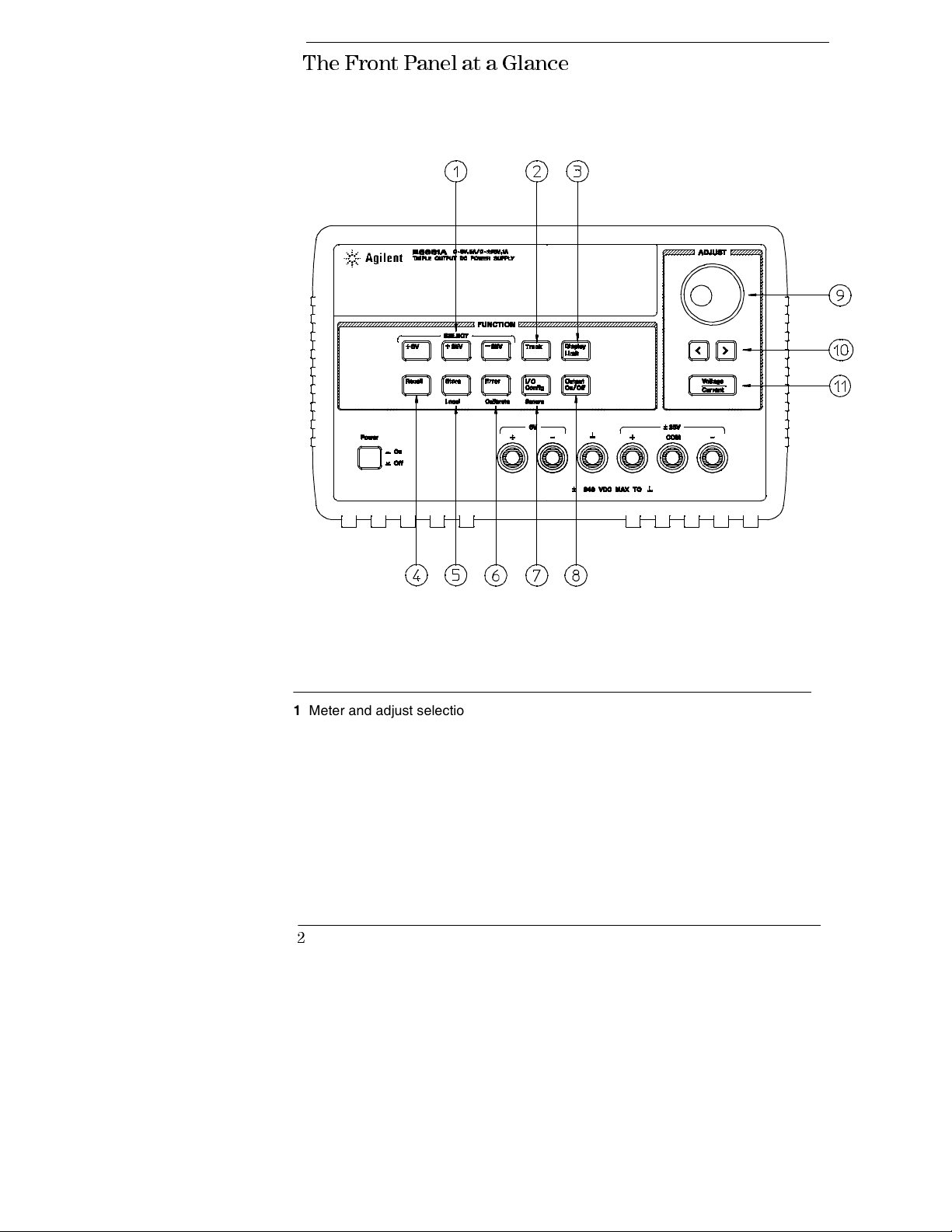
The Front Panel at a Glanc e
1 Meter and adjust selection keys
2 Tracking enable/disable key
3 Display limit key
4 Recall operating state key
5 Store operating state/Local key
6 Error/Calibrate key
2
7 I/O Configuration / Secure key
8 Output On/Off key
9 Control knob
10 Resolution selection keys
11 Voltage/current adjust selection key
Page 4
1 Meter and adjust selection keys Select the output voltage and current of any one
supply (+6V, +25V, or -25V output) to be monitored on the display and allow knob
adjustment of that supply.
2 Tracking enable / disable key Enables / disables the track mode of ±25V supplies.
3 Display limit key Shows the voltage and current limit values on the display and
allows knob adjustment for setting limit values.
4 Recall operating state key Recalls a previously stored operating state from
location “1”, “2”, or “3”.
5 Store operating state / Local key
or “3” / or returns the power supply to local mode from remote interface mode.
6 Error / Calibrate key
and calibration / or enables calibration mode (the power supply must be unsecured
before performing calibration).
2
Displays error codes generated during operations, self-test
7 I/O Configuration / Secure key
interfaces / or secure and unsecure the power supply for calibration.
1
Stores an operating state in location “1”, “2”,
3
Configures the power supply for remote
8 Output On/Off key Enables or disables all three power supply outputs. This key
toggles between two states.
9 Control knob Increases or decreases the value of the blinking digit by turning
clockwise or counter clockwise.
10 Resolution selection keys Move the flashing digit to the right or left.
11 Voltage/current adjust selection key Selects the knob function to voltage control or
current control.
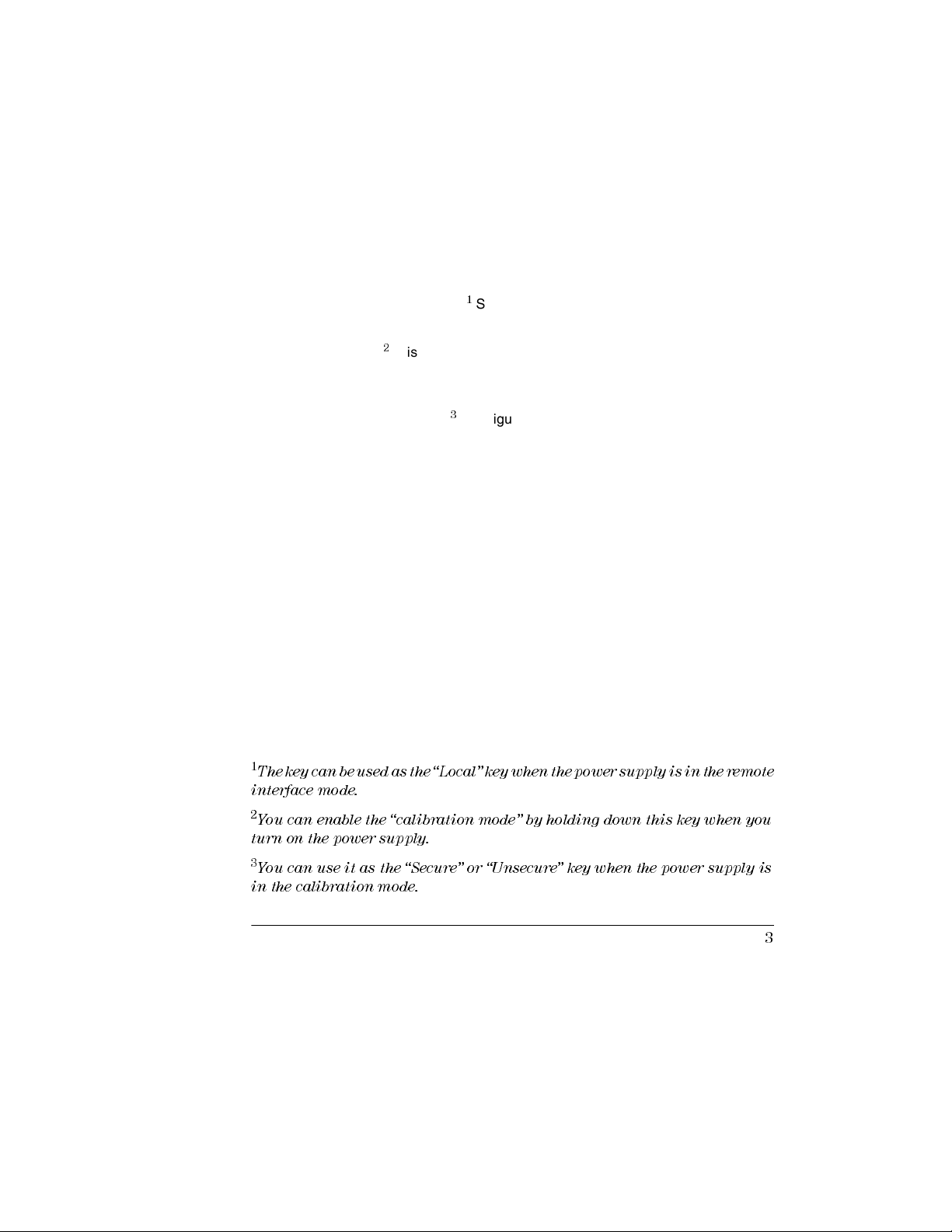
1
The key can be used as the “Local” key when the power supply is in the remote
interface m ode.
2
You can enable the “calibration mode” by holding down this key when you
turn on the power supply.
3
You can use it as the “Secure” or “Unsecure” key when the power supply is
in the calibration mode.
3
Page 5
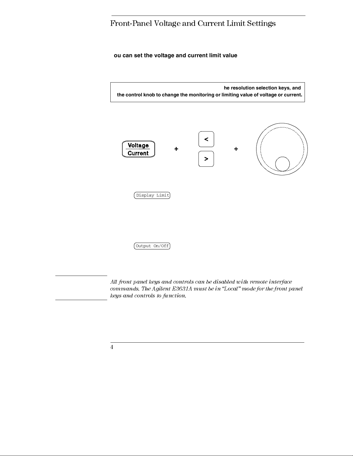
Front-Pan el Vo ltag e and Current Limi t Set tin gs
You can set the voltage and current limit values from the front panel
using the following method.
Use the voltage/current adjust selection key, the resolution selection keys, and
the control knob to change the monitoring or limiting value of voltage or current
.
Note
1 Press the key after turning on the power supply.
Display Limit
2 Set the knob to the voltage control mode or current control mode using the
voltage/current adjust selection key.
3 Move the blinking digit to the appropriate position using the resolution selection keys.
4 Change the blinking digit to the desired value using the control knob.
5 Press the key to enable the output. After about 5 seconds, the
display will go to the output monitor mode automatically to display the voltage
and current at the output.
Output On/Off
All front panel keys and controls can be disabled with remote interface
commands. The Agilent E3631A must be in “Local” mode for the front panel
keys and controls to function.
4
Page 6
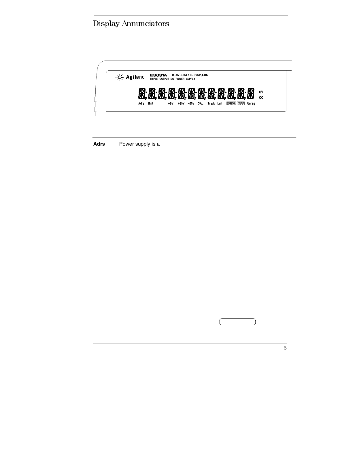
Display Annunciators
Adrs Power supply is addressed to listen or talk over a remote interface.
Rmt Power supply is in remote interface mode.
+6V Displays the output voltage and current for +6V supply. Knob is active for
+6V supply.
+25V Displays the output voltage and current for +25V supply. Knob is active for
+25V supply.
-25V Displays the output voltage and current for -25V supply. Knob is active for
-25V supply.
CAL power supply is in calibration mode.
Track The outputs of +25V and -25V supplies are in track mode.
Limit The display shows the voltage and current limit value of a selected supply.
ERROR Hardware or remote interface command errors are detected and also the
error bit has not been.
OFF The three ouputs of the power supply are disabled.
Unreg The displayed output is unregulated (output is neither CV nor CC).
CV The displayed output is in constant-voltage mode.
CC The displayed output is in constant-current mode.
To review the display annunciators, hold down key as you
Display Limit
turn on the power supply.
5
Page 7
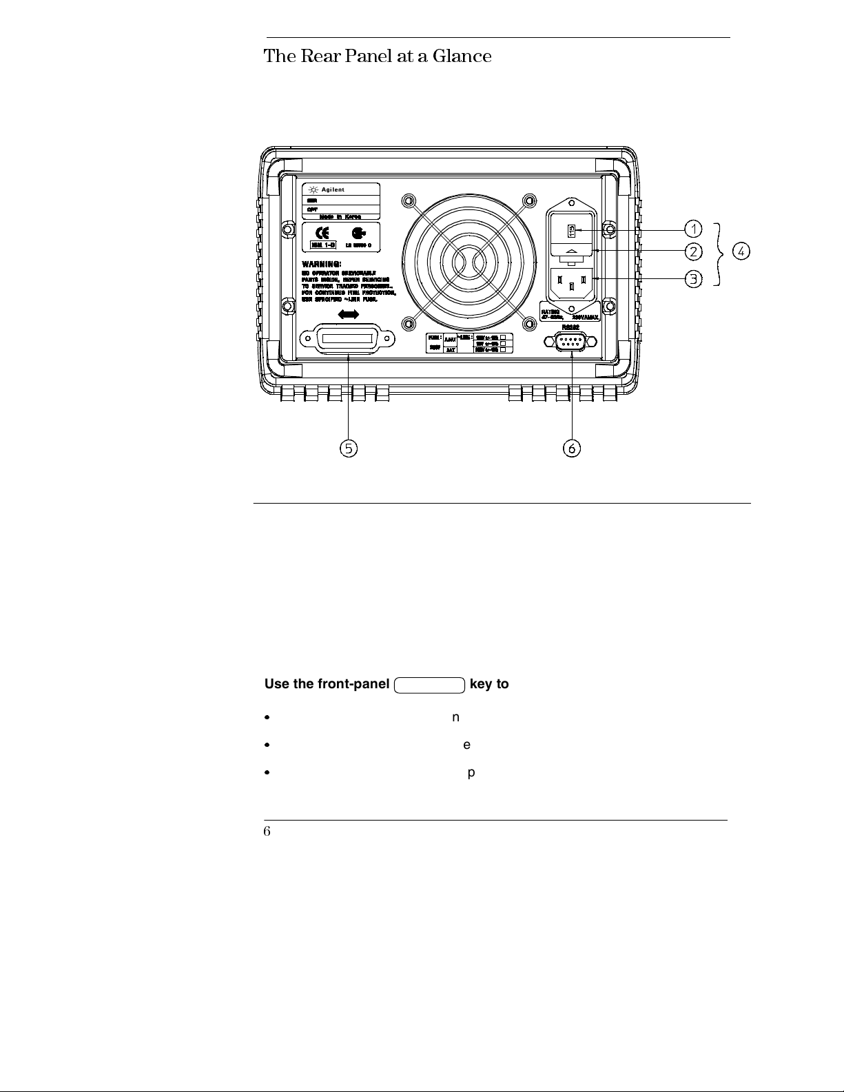
The Rear Panel at a Glance
1 Power-line voltage setting
2 Power-line fuse-holder assembly
3 AC inlet
Use the front-panel key to:
•
Select the GPIB or RS-232 interface (see chapter 3).
•
Set the GPIB bus address (see chapter 3).
•
Set the RS-232 baud rate and parity (see chapter 3).
I/O Config
4 Power-line module
5 GPIB (IEEE-488) interface connector
6 RS-232 interface connector
6
Page 8
In This Book
General Information
power supply. This chapter also provides instructions for checking your
power supply, connecting to ac power, and selecting power-line voltage.
Initial Operation
rated outputs and properly responds to operation from the front panel.
Front-Panel Operation
front-panel keys and how they are used to operate the power supply from
the front panel. This chapter also shows how to configure the power supply
for the remote interface and gives a brief introduction to the calibration
features.
Remote Interface Reference
to help you program the power supply over the remote interface. This
chapter also explains how to program for status reporting.
Error Messages
are working with the power supply. Each listing contains i n formation to help
you diagnose and solve the problem.
Application Programs
applications to help you develop programs for your application.
Tutorial
gives specific details on the operation and use of the Agilent E3631A power
supplies.
Chapter 7 describes basic operation of linear power supplies and
Chapter 1 contains a general description of your
Chapter 2 ensures that the power supply develops its
Chapter 3 describes in detail the use of
Chapter 4 contains reference information
Chapter 5 lists the error messages that may appear as you
Chapter 6 contains some remote interface
Specifications
If you have questions re la ting to the operation of the power suppl y, call
1-800-829-4444
Technologies Sales Office.
Chapter 8 lists the power supply’s specifications .
in the United States, or contac t your ne are st A gile nt
7
Page 9

8
Page 10
Contents
Chapter 1 General Information
Safety Considerations- - - - - - - - - - - - - - - - - - - - - - - - - - - - - - - - - - 15
Safety and EMC Requirements - - - - - - - - - - - - - - - - - - - - - - - - - 15
Options and Accessories - - - - - - - - - - - - - - - - - - - - - - - - - - - - - - - 16
Options - - - - - - - - - - - - - - - - - - - - - - - - - - - - - - - - - - - - - - - - - - - - 16
Accessories- - - - - - - - - - - - - - - - - - - - - - - - - - - - - - - - - - - - - - - - - 16
Description - - - - - - - - - - - - - - - - - - - - - - - - - - - - - - - - - - - - - - - - - - 17
Installation - - - - - - - - - - - - - - - - - - - - - - - - - - - - - - - - - - - - - - - - - - 19
Initial Inspection - - - - - - - - - - - - - - - - - - - - - - - - - - - - - - - - - - - - 19
Cooling and Location- - - - - - - - - - - - - - - - - - - - - - - - - - - - - - - - - 19
Input Power Requirements- - - - - - - - - - - - - - - - - - - - - - - - - - - - - - 22
Power-Line Cord - - - - - - - - - - - - - - - - - - - - - - - - - - - - - - - - - - - - 22
Power-Line Voltage Selection - - - - - - - - - - - - - - - - - - - - - - - - - - 22
Chapter 2 Initial Operation
Preliminary Checkout- - - - - - - - - - - - - - - - - - - - - - - - - - - - - - - - - - 27
Power-On Checkout - - - - - - - - - - - - - - - - - - - - - - - - - - - - - - - - - - - 28
Output Checkout- - - - - - - - - - - - - - - - - - - - - - - - - - - - - - - - - - - - - - 29
Voltage Output Checkout - - - - - - - - - - - - - - - - - - - - - - - - - - - - - 29
Current Output Checkout - - - - - - - - - - - - - - - - - - - - - - - - - - - - - 31
Contents
Chapter 3 Front-Panel Operation
Front-Panel Operation Overview- - - - - - - - - - - - - - - - - - - - - - - - - 35
Constant Voltage Operation - - - - - - - - - - - - - - - - - - - - - - - - - - - - - 36
Constant Current Operation- - - - - - - - - - - - - - - - - - - - - - - - - - - - - 38
Tracking Operation- - - - - - - - - - - - - - - - - - - - - - - - - - - - - - - - - - - - 40
Storing and Recalling Operating States - - - - - - - - - - - - - - - - - - - - 41
Disabling the Outputs- - - - - - - - - - - - - - - - - - - - - - - - - - - - - - - - - - 43
Knob Locking - - - - - - - - - - - - - - - - - - - - - - - - - - - - - - - - - - - - - - - - 43
System-Related Operations - - - - - - - - - - - - - - - - - - - - - - - - - - - - - 44
Self-Test - - - - - - - - - - - - - - - - - - - - - - - - - - - - - - - - - - - - - - - - - - - 44
Error Conditions - - - - - - - - - - - - - - - - - - - - - - - - - - - - - - - - - - - - 45
Display Control - - - - - - - - - - - - - - - - - - - - - - - - - - - - - - - - - - - - - 46
Firmware Revision Query - - - - - - - - - - - - - - - - - - - - - - - - - - - - - 47
SCPI Language Version - - - - - - - - - - - - - - - - - - - - - - - - - - - - - - - 47
9
Page 11
Contents
Chapter 3 Front-Panel Operation (continued)
Remote Interface Configuration - - - - - - - - - - - - - - - - - - - - - - - - - - 48
Remote Interface Selection - - - - - - - - - - - - - - - - - - - - - - - - - - - - 48
GPIB Address - - - - - - - - - - - - - - - - - - - - - - - - - - - - - - - - - - - - - - - 49
Baud Rate Selection (RS-232) - - - - - - - - - - - - - - - - - - - - - - - - - - 49
Parity Selection (RS-232) - - - - - - - - - - - - - - - - - - - - - - - - - - - - - - 49
To Set the GPIB Address - - - - - - - - - - - - - - - - - - - - - - - - - - - - - - 50
To Set the Baud Rate and Parity (RS-232)- - - - - - - - - - - - - - - - - 51
GPIB Interface Configuration - - - - - - - - - - - - - - - - - - - - - - - - - - - - 53
RS-232 Interface Configuration- - - - - - - - - - - - - - - - - - - - - - - - - - - 54
RS-232 Configuration Overview - - - - - - - - - - - - - - - - - - - - - - - - - 54
RS-232 Data Frame Format - - - - - - - - - - - - - - - - - - - - - - - - - - - - 54
Connection to a Computer or Terminal- - - - - - - - - - - - - - - - - - - 55
DTR/DSR Handshake Protocol - - - - - - - - - - - - - - - - - - - - - - - - - 56
RS-232 Troubleshooting - - - - - - - - - - - - - - - - - - - - - - - - - - - - - - - 57
Calibration Overview - - - - - - - - - - - - - - - - - - - - - - - - - - - - - - - - - - 58
Calibration Security - - - - - - - - - - - - - - - - - - - - - - - - - - - - - - - - - - 58
Calibration Count - - - - - - - - - - - - - - - - - - - - - - - - - - - - - - - - - - - - 62
Calibration Message - - - - - - - - - - - - - - - - - - - - - - - - - - - - - - - - - - 62
Chapter 4 Remote Interface Reference
SCPI Command Summary- - - - - - - - - - - - - - - - - - - - - - - - - - - - - - - 65
Simplifi ed Program mi ng Overview- - - - - - - - - - - - - - - - - - - - - - - - 70
Using the
Using the Low-Level Comm ands - - - - - - - - - - - - - - - - - - - - - - - - 70
Reading a Query Response- - - - - - - - - - - - - - - - - - - - - - - - - - - - - 71
Selecting a Trigger Source - - - - - - - - - - - - - - - - - - - - - - - - - - - - - 71
Programming Ranges and Output Identifiers - - - - - - - - - - - - - - 72
Using the APPLy Command - - - - - - - - - - - - - - - - - - - - - - - - - - - - - 73
Output Setting and Operation Commands - - - - - - - - - - - - - - - - - - 74
Output Selection Commands - - - - - - - - - - - - - - - - - - - - - - - - - - - 74
Measurement Commands- - - - - - - - - - - - - - - - - - - - - - - - - - - - - - 76
Output On/Off and Tracking Operation Commands - - - - - - - - - 77
Output Setting Commands - - - - - - - - - - - - - - - - - - - - - - - - - - - - - 77
Triggering Commands- - - - - - - - - - - - - - - - - - - - - - - - - - - - - - - - - - 79
Trigger Source Choices - - - - - - - - - - - - - - - - - - - - - - - - - - - - - - - 79
Triggering Commands - - - - - - - - - - - - - - - - - - - - - - - - - - - - - - - - 81
10
APPLy
Command - - - - - - - - - - - - - - - - - - - - - - - - - - - 70
Page 12
Contents
Chapter
System-Related Commands - - - - - - - - - - - - - - - - - - - - - - - - - - - - - 82
Calibration Commands- - - - - - - - - - - - - - - - - - - - - - - - - - - - - - - - - 85
RS-232 Interface Commands - - - - - - - - - - - - - - - - - - - - - - - - - - - - 87
The SCPI Status Registers - - - - - - - - - - - - - - - - - - - - - - - - - - - - - - 88
What is an
What is an
What is a
SCPI Status System - - - - - - - - - - - - - - - - - - - - - - - - - - - - - - - - - - 90
The Questionable Status Register - - - - - - - - - - - - - - - - - - - - - - - 91
The Standard Event Register- - - - - - - - - - - - - - - - - - - - - - - - - - - 93
The Status Byte Register - - - - - - - - - - - - - - - - - - - - - - - - - - - - - - 94
Using Service Request (SRQ) and Serial POLL - - - - - - - - - - - - - 95
Using *STB? to Read the Status Byte - - - - - - - - - - - - - - - - - - - - 96
Using the Message Available Bit (MAV) - - - - - - - - - - - - - - - - - - 96
To Interrupt Your Bus Controll er Usi ng SRQ - - - - - - - - - - - - - - 96
To Determine When a Command Sequence is Com pl eted- - - - 97
Using *OPC to Signal When Data is in the Output Buffer - - - - 97
Status Reporting Commands - - - - - - - - - - - - - - - - - - - - - - - - - - - - 98
An Introduction to the SCPI Language - - - - - - - - - - - - - - - - - - - 102
Command Format Used in This Manual - - - - - - - - - - - - - - - - - 103
Command Separators - - - - - - - - - - - - - - - - - - - - - - - - - - - - - - - 104
Using the
Querying Parameter Settings- - - - - - - - - - - - - - - - - - - - - - - - - - 105
SCPI Command Terminators- - - - - - - - - - - - - - - - - - - - - - - - - - 105
IEEE-488.2 Common Commands - - - - - - - - - - - - - - - - - - - - - - 105
SCPI Parameter Types- - - - - - - - - - - - - - - - - - - - - - - - - - - - - - - 106
Halting an Output in Progress - - - - - - - - - - - - - - - - - - - - - - - - - - 107
SCPI Conformance Information- - - - - - - - - - - - - - - - - - - - - - - - - 108
IEEE-488 Conformance information - - - - - - - - - - - - - - - - - - - - - 111
4
Remote Interface Reference (continued)
Event
Register? - - - - - - - - - - - - - - - - - - - - - - - - - - - - 88
Enable
Multiple
MIN
Register? - - - - - - - - - - - - - - - - - - - - - - - - - - - 88
Logical Output?- - - - - - - - - - - - - - - - - - - - - - 88
and MAX parameters- - - - - - - - - - - - - - - - - - - - 104
Contents
Chapter 5 Error Messages
Execution Errors - - - - - - - - - - - - - - - - - - - - - - - - - - - - - - - - - - - - 115
Self-Test Errors- - - - - - - - - - - - - - - - - - - - - - - - - - - - - - - - - - - - - - 120
Calibration Errors- - - - - - - - - - - - - - - - - - - - - - - - - - - - - - - - - - - - 121
11
Page 13
Contents
Chapter 6 Application Programs
Agilent BASIC Programs- - - - - - - - - - - - - - - - - - - - - - - - - - - - - - - 124
C and QuickBASIC Language Programs- - - - - - - - - - - - - - - - - - - 124
Using the APPLy Command - - - - - - - - - - - - - - - - - - - - - - - - - - - - 125
Using the Low-Level Commands - - - - - - - - - - - - - - - - - - - - - - - - 129
Using the Status Registers - - - - - - - - - - - - - - - - - - - - - - - - - - - - - 133
RS-232 Operation Using QuickBA SIC- - - - - - - - - - - - - - - - - - - - - 135
Chapter 7 Tutorial
Overview of Agilent E3631A Operation - - - - - - - - - - - - - - - - - - - 139
Output Characteristics - - - - - - - - - - - - - - - - - - - - - - - - - - - - - - - - 141
Unregulated State- - - - - - - - - - - - - - - - - - - - - - - - - - - - - - - - - - - 143
Unwanted Signals- - - - - - - - - - - - - - - - - - - - - - - - - - - - - - - - - - - 143
Connecting the Load - - - - - - - - - - - - - - - - - - - - - - - - - - - - - - - - - - 145
Output Isolation - - - - - - - - - - - - - - - - - - - - - - - - - - - - - - - - - - - - 145
Multiple Loads - - - - - - - - - - - - - - - - - - - - - - - - - - - - - - - - - - - - - 145
Load Consideration - - - - - - - - - - - - - - - - - - - - - - - - - - - - - - - - - 146
Extending the Voltage- - - - - - - - - - - - - - - - - - - - - - - - - - - - - - - - - 148
Series Connections- - - - - - - - - - - - - - - - - - - - - - - - - - - - - - - - - - 148
Remote Programming- - - - - - - - - - - - - - - - - - - - - - - - - - - - - - - - - 149
Reliability- - - - - - - - - - - - - - - - - - - - - - - - - - - - - - - - - - - - - - - - - - - 151
Chapter 8 Specifications
Performance Specifications - - - - - - - - - - - - - - - - - - - - - - - - - - - - 155
Supplemental Characteristics - - - - - - - - - - - - - - - - - - - - - - - - - - - 157
Index - - - - - - - - - - - - - - - - - - - - - - - - - - - - - - - - - - - - - - -161
12
Page 14

1
1
General Information
Page 15

General Information
This chapter provides a general description of your power supply. This
chapter also contains instructions for initial inspection, location and cooling
for bench and rack operation, selecting the power-line voltage, and
connecting your power supply to ac power.
14
Page 16
Chapter 1 General Information
Safety Considerations
Safety Considerat ion s
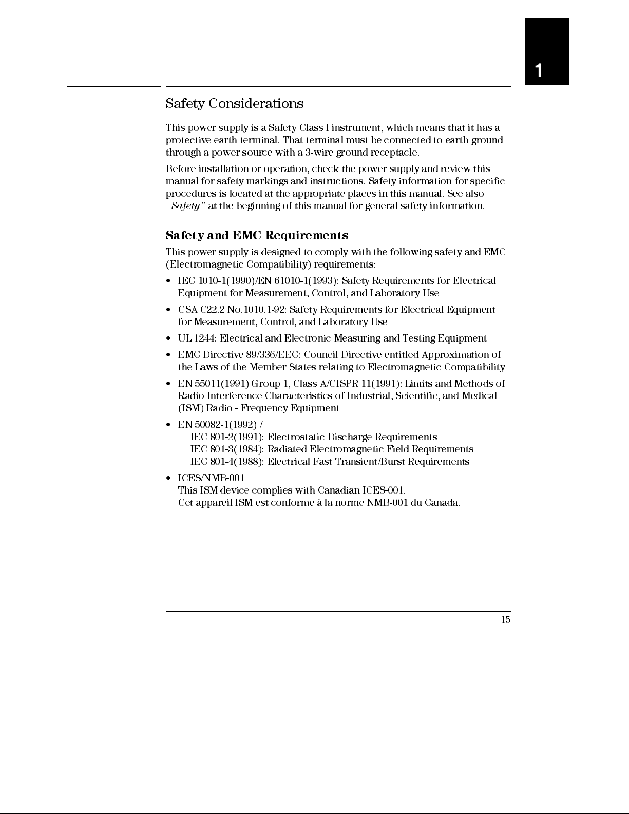
This power supply is a Safety Class I instrument, which means that it has a
protective earth terminal. That terminal must be connected to earth ground
through a power source with a 3-wire ground receptacle.
Before installation or operation , check the power supply and review this
manual for safety markings and instructions. Safety information for specific
procedures is located at the appropriate places in this manual. See also
“
Safety” at the beginning of this manual for general safety information.
Safety and EMC Requirements
This power supply is designed to comply with the following safety and EMC
(Electromagnetic Compatibility) requirements:
• IEC 1010-1(1990)/EN 61010-1(1993): Safety Requirements for Electrical
Equipment for Measurement, Control, and Laboratory Use
• CSA C22.2 No.1010.1-92: Safety Requirements for Electrical Equipment
for Measurement, Control, and Laboratory Use
• UL 1244: Electrical and Electronic Measuring and Testin g Equipm ent
• EMC Directive 89/336/EEC: Council Directive entitled Approximation of
the Laws of the Member States relating to Electromagnetic Compatibility
• EN 55011(1991) Group 1, Class A/CISPR 11(1991): Limits and Methods of
Radio Interference Characteristics of Industrial, Scientific, and Medical
(ISM) Radio - Frequency Equipment
• EN 50082-1(1992) /
IEC 801-2(1991): Electrostatic Discharge Requirements
IEC 801-3(1984): Radiated Electromagnetic Fi eld Requi rements
IEC 801-4(1988): Electrical Fast Transient/Burst Requirements
• ICES/NMB-001
This ISM device complies with Canadian ICES-001.
Cet appareil ISM est conforme à la norme NMB-001 du Canada.
1
15
Page 17
Chapter 1 General Information
Options and Accessories
Options and Accessories
Options
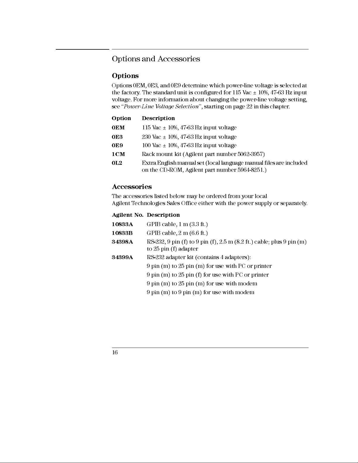
Options 0EM, 0E3, and 0E9 determine which power-line voltage is selected at
the factory. The standard unit is configured for 115 Vac ± 10%, 47-63 Hz input
voltage. For more information about changing the power-line voltage setting,
see ‘‘
Power-Line Voltage Selection
Option Description
0EM
0E3
0E9
100 Vac ± 10%, 47-63 Hz input voltage
1CM
0L2
115 Vac ± 10%, 47-63 Hz input voltage
230 Vac ± 10%, 47-63 Hz input voltage
Rack mount kit (Agilent part number 5062-3957)
Extra English manual set (local language manual files are included
on the CD-ROM, A gilent part number 5964-8251.)
’’, starting on page 22 in this c h a pt e r.
Accessories
The accessories listed below may be ordered from your local
Agilent Technologies Sales Office either with the power supply or separately.
Agilent No. Description
10833A
10833B
34398A
34399A
16
GPIB cable, 1 m (3.3 ft.)
GPIB cable, 2 m (6.6 ft.)
RS-232, 9 pin (f) to 9 pin (f), 2.5 m (8.2 ft.) cable; plus 9 pin (m)
to 25 pin (f) adapter
RS-232 adapter kit (contains 4 adapters):
9 pin (m) to 25 pin (m) for use with PC or printer
9 pin (m) to 25 pin (f) for use with PC or printer
9 pin (m) to 25 pin (m) for use with modem
9 pin (m) to 9 pin (m) for use with modem
Page 18
Chapter 1 General Information
Description
Description
The Agilent E3631A power supply features a combination of programming
capabilities and linear power supply performance that makes it ideal for
power systems applications. The triple power supply delivers 0 to ± 25 V
outputs rated at 0 to 1 A and 0 to +6 V output rated at 0 to 5 A. The ± 25V
supplies also provide 0 to ± 25 V tracking output to power operational
amplifiers and circuits requiring symmetrically balanced voltages. The 0 to
± 25V outputs track each other within ±(0.2% output + 20 mV) in the track
mode. The ± 25V outputs can also be used in series as a single 0 to 50 V/1 A
supply.
The voltage and current of each supply can be adjusted independently from
the front panel or programmed over the GPIB or RS-232 interface. Using the
front panel keys and the control knob, you can adjust the voltage and
current of a selected output; enable or disable track mode; store and recall
operating states; enable or disable three outputs; calibrate the power supply
including changing the calibration security; return the power supply to local
operating mode; and configure the power supply for remote interface
operation.
From the front-panel VFD (vacuum-fl uores cent displ ay), you can monitor
actual values of output voltage and current (
current limit values (
supply from the annunciators, and check the type of error from the
displayed error codes (messages).
When operated over the remote interface, the power supply can be both a
listener and a talker. Using an external controller, you can instruct the
power supply to set outputs and to send the status data back over the GPIB or
RS-232. Readback capabilities includ e reading back output voltage and
current; present and stored status; and error messages. The following
functions are implemented over the GPIB or RS-232:
limit mode
), check the operating status of the power
meter mode
) or voltage and
1
• Voltage and current programming
• Voltage and current readback
• Enable or disable track mode
• Present and stored status readback
• Programming syntax error detection
• Voltage and current calibration
• Output on or off
• Self-test
17
Page 19
Chapter 1 General Information
Description
The front panel includes a VFD for displaying the output voltage and
current. Two 4-digit voltage and current meters accurately show the actual
or limit values of a selected supply simultaneously. Three meter selection
keys choose the voltage and current of any one output to be monitored on
the display.
Connections to the power supply's output and to chassis ground are made to
binding posts on the front panel. The +25V and -25V supply's outputs share a
common output terminal which is isolated from chassis ground. The positive
and negative terminals of each output can be grounded, or each output can
be kept within ±240 Vdc from the chassis ground. The power supply is
shipped with a detachable, 3-wire grounding type power cord. The ac line
fuse is an extractor type on the rear panel.
The power supply can be calibrated from the front panel directly or with a
controller over the GPIB or RS-232 interface using calibration commands.
Co r r e c t io n fact o rs are st o red i n
output programming. Calibration from the front panel or a controller
eliminates the need to remove the top cover or even the need to remove the
power supply from your system cabinet. You can guard against unauthorized
calibration by using the “Secured” calibration protection function.
non-volatile
memory and are used during
18
Page 20
Chapter 1 General Information
Installation
Installation
Initial Inspection
When you receive your power supply, inspect it for any obvious damage that
may have occurred during shipment. If any damage is found, notify the
carrier and the nearest Agilent Sales Office immediately. Warranty information
is shown in the front of this manual.
Keep the original packing materials in case the power supply has to be
returned to Agilent Technologies in the future. If you return the power supply
for service, attach a tag identifying the owner and model number. Also include
a brief description of the problem.
Mechanical Check
This check confirms that there are no broken keys or knob, that the cabinet
and panel surfaces are free of dents and scratches, and that the display is not
scratched or cracked.
Electrical Check
Chapter 2 describes an initial operation procedure which, when successfully
completed, verifies to a high level of confidence that the power supply is
operating in accordance with its specifications. Detailed electrical
verification procedures are included in the
Service Gu ide
.
1
Cooling and Location
Cooling
The power supply can operate without loss of performance within the
temperature range of 0 °C to 40 °C, and with derated output current from
40 °C to 55 °C. A fan cools the power supply by drawing air through the rear
panel and exhausting it out the sides. Using an Agilent rack mount will not
impede the flow of air.
Bench Operation
Your power supply must be installed in a location that allows sufficient
space at the sides and rear of the power supply for adequate air circulation.
The rubber bumpers must be removed for rack mounting.
19
Page 21
Chapter 1 General Information
Installation
Rack Mounting
The power supply can be mounted in a standard 19-inch rack cabinet using
one of three optional kits available. A rack-mounting kit for a single
instrument is availabl e as Option 1CM (P /N 5063-9243). Installatio n
instructions and hardware are included with each rack-mounting kit. Any
Agilent System II instrument of the same size can be rack-mounted beside the
Agilent E3631A power supply.
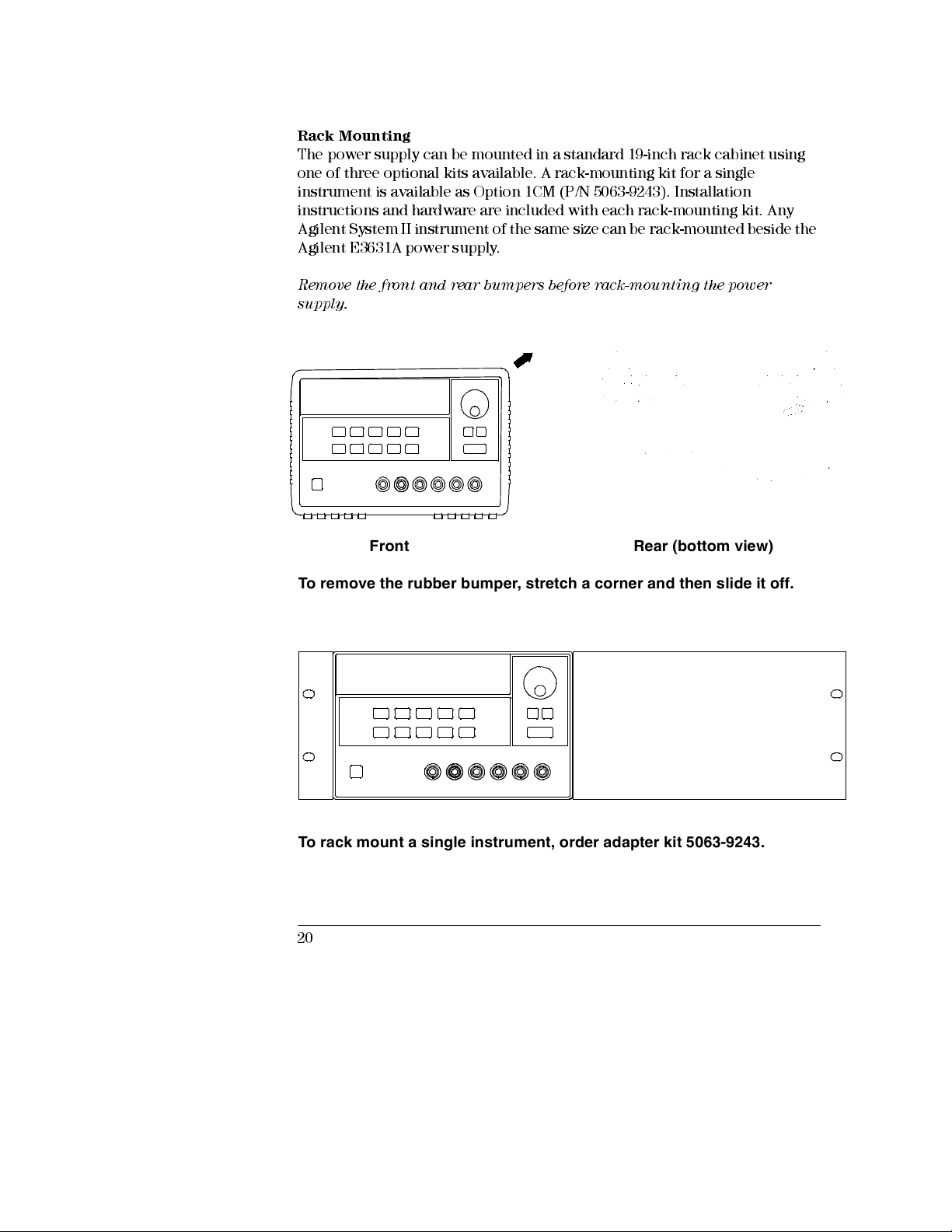
Remove the fron t and rear bum per s before rac k-mou ntin g the power
supply.
Front Rear (bottom view)
To remove the rubber bumper, stretch a corner and then slide it off.
To rack mount a single instrument, order adapter kit 5063-9243.
20
Page 22
Chapter 1 General Information
Installation
To rack mount two instruments of the same depth side-by-side, order
lock-link kit 5061-9694 and flange kit 5063-9214.
1
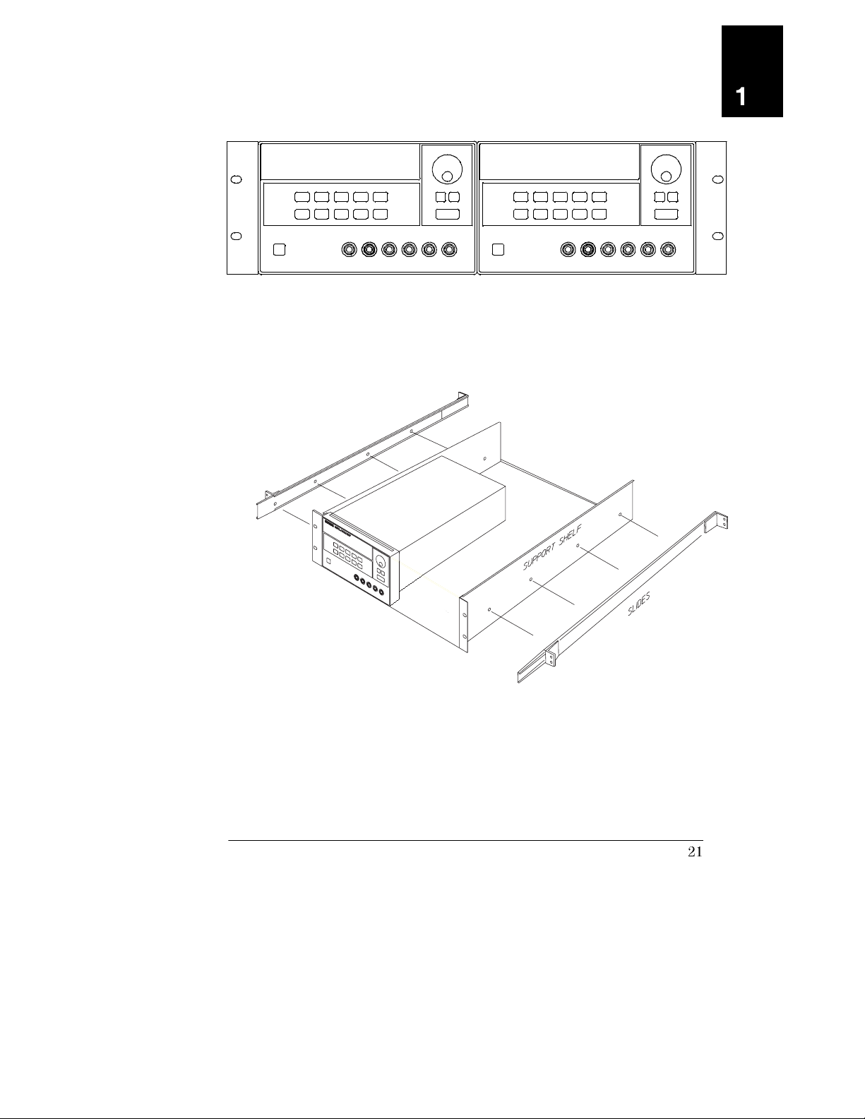
To install two instruments in a sliding support shelf, order support shelf
5063-9256, and slide kit 1494-0015.
21
Page 23
Chapter 1 General Information
Input Power Requirements
Input Power Requirements
You can operate your power supply from a nominal 100 V, 115 V, or 230 V
single phase ac power source at 47 to 63 Hz. An indication on the rear panel
shows the nominal inp ut voltage set for the power supply at the factory. If
necessary, you can change the power-line voltage setting according to the
instructions on the next page.
Power-Line Cord
The power supply is shipped from the factory with a power-line cord that
has a plug appropriate for your location. Contact the nearest Agilent Sales and
Service Office if the wrong power-line cord is included with your power
supply. Your power supply is equipped with a 3-wire grounding type power
cord; the third conductor being the ground. The power supply is grounded
only when the power-line cord is plugged into an appropriate receptacle. Do
not operate your power supply without adequate cabinet ground connection.
Power-Line Voltage Selection
Power-line voltage selection is accomplished by adjusting two components:
power-line voltage selector and power-line fuse on the power-line module of
the rear panel. To change the power-line voltage, proceed as follows:
22
Page 24
Chapter 1 General Information
Input Power Requirements
1
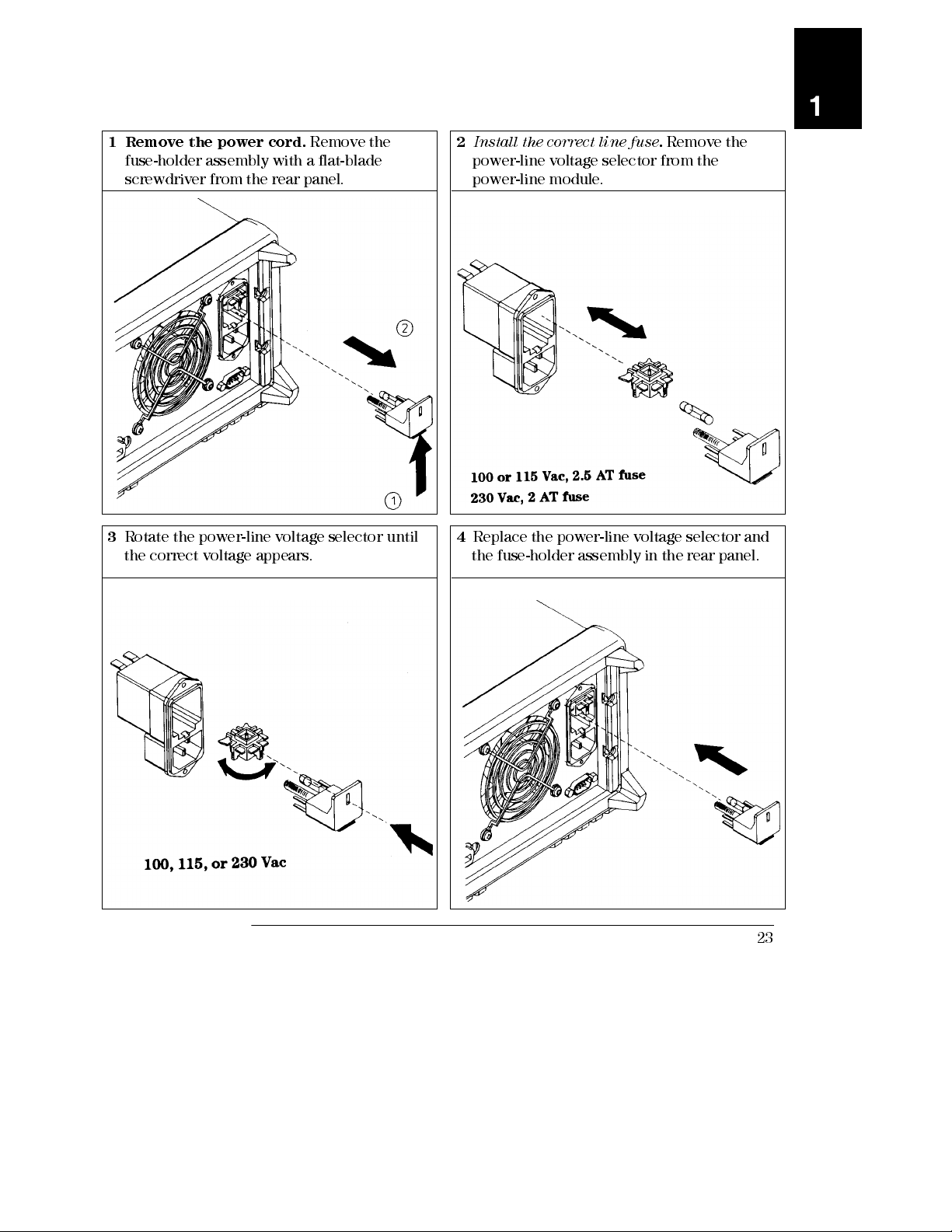
1 Remove the power cord.
fuse-holder assembly with a flat-blade
screwdriver from the rear panel.
3
Rotate the power-line voltage selector until
the correct voltage appears.
Remove the
2 Install the correct line fuse. Remove the
power-line voltage selector from the
power-line module.
4
Replace the power-line voltage selector and
the fuse-holder assemb ly in the rear panel.
23
Page 25

24
Page 26
2
2
Initial Operation
Page 27
Initial Operation
There are three basic tests in this chapter. The automatic power-on test
includes a self-test that checks the internal microprocessors and allows the
user visually to check the display. The output check ensures that the power
supply develops its rated outputs and properly responds to operation from
the front panel. For complete performance and/or verification tests, refer to
the
Service Guid e
This chapter is intended for both the experienced and the inexperienced
user because it calls attention to certain checks that should be made prior to
operation.
Throughout this chapter the key to be pressed is shown in the left margin.
.
26
Page 28
Chapter 2 Initial Operation
Preliminary Checkout
Preliminary Checkout
The following steps help you verify that the power supply is ready for use.
1 Verify the power-line voltage setting on the rear panel.
The power-line voltage is set to the proper value for your country when the
power supply is shipped from the factory. Change the voltage setting if it is
not correct. The settings are: 100, 115, or 230 Vac.
2 Verify that the correct power-line fuse is installed.
The correct fuse is installed for your country when the power supply is
shipped from the factory. For 100 or 115 Vac operation, you must use a
2.5 AT fuse. For 230 Vac operation, you must use a 2.0 AT fuse.
3 Connect the power-line cord and turn on your power supply.
The front-panel display will light up and a power-on self-test occurs
automatically when you turn on the power supply.
See “Power-Line Voltage Selection ”, star ting on page 22 in ch apter 1 if you
need to change the power-line voltage or the powe r-line fuse .
To replace the 2.5 AT fuse, order A gile nt part nu m ber 2110-0913.
To replace the 2 AT fuse, order Agilent part number 2110-0982.
2
27
Page 29
Chapter 2 Initial Operation
Power-On Checkout
Power-On Checkout
The power-on test includes an automatic self-test that checks the internal
microprocesso rs and allow s the user visuall y to check the display. You will
observe the following sequence on the display after pressing the front panel
power switch to on.
Output On/Off
1 All segments of the display including all annunciators will turn on
for about one second.
To review the annunciators , hold down the key as you
Display Limit
turn on the power supply.
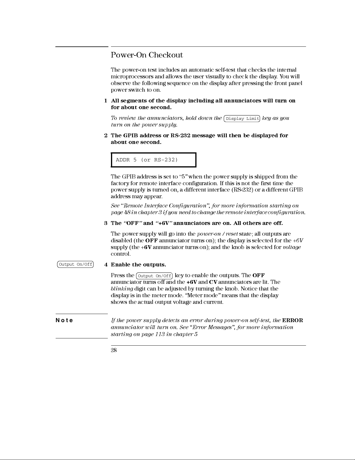
2 The GPIB address or RS-232 message will then be displayed for
about one second.
ADDR 5 (or RS-232)
The GPIB address is set to “5” when the power supply is shipped from the
factory for remote interface configuration. If this is not the first time the
power supply is turned on, a different interface (RS-232) or a different GPIB
address may appear.
See ‘‘Remote Interface Configuration’’, for more information starting on
page 48 in chapter 3 if you ne ed to ch ange t he remot e inte rface co nfig urati on.
3The “OFF” and “+6V” annunciators are on. All others are off.
The power supply will go into the
disabled (the
supply (the +
OFF
annunciator turns on); the display is selected for the +6V
6V
annunciator turns on); and the knob is selected for
power-on / reset
state; all outputs are
voltage
control.
4 Enable th e outputs.
Note
Press the
Output On/Off
annunciator turns off and the
blinking
digit can be adjusted by turning the knob. Notice that the
key to enable the outputs. The
+6V
and CV annunciators are lit. The
OFF
display is in the meter mode. “Meter mode” means that the display
shows the actual output voltage and current.
If the power supply detects an error during power-on self-test, the
annunciator will turn on.
See “Err or Me ss ages ”, for m ore inform ation
starting on page 113 in chapter 5
28
ERROR
Page 30
Chapter 2 Initial Operation
Output Checkout
Output Check out
Power
Output On/Off
The following procedures check to ensure that the power supply develops
its rated outputs and properly responds to operation from the front panel.
For complete performance and verification tests, refer to the
For each step, use the keys shown on the left margins.
Service Guid e
Voltage Output Checkout
The following steps verify basic voltage functions with no load.
1 Turn on the power supply.
The power supply will go into the
disabled (the
supply (the
control.
2 Enable th e outputs.
The
OFF
blinking
in the meter mode. “Meter mode” means that the display shows the actual
output voltage and current.
3 Check that the front-panel voltmeter properly responds to knob
control for the +6V supply.
Turn the knob clockwise or counter clockwise to check that the voltmeter
responds to knob control and the ammeter indicates nearly zero.
OFF
annunciator turns on); the display is selected for the +6V
+6V
annunciator turns on); and the knob is selected for
annunciator turns off and the
digit can be adjusted by turning the knob. Notice that the display is
power-on / reset
+6V
and
CV
state; all outputs are
voltage
annunciators are lit. The
2
.
4 Ensure that the voltage can be adjusted from zero to the maximum
rated value.
Adjust the knob until the voltmeter indicates 0 volts and then adjust the
knob until the voltmeter indicates 6.0 volts.
1
You can use the resolution selection keys to move the blinking digit to the right or
left when setting the voltage.
1
29
Page 31

Chapter 2 Initial Operation
Output Checkout
+25V
-25V
5 Check the voltage function for the +25V supply.
Select the meter and adjust selection key for the +25V supply. The CV
annunciator is still lit and the
+25V
annunciator will turn on. Repeat steps
(3) and (4) to check the voltage function for the +25V supply.
6 Check the voltage function for the -25V supply.
Select the meter and adjust selection key for the -25V supply. The CV
annunciator is still lit and the
-25V
annunciator will turn on. Repeat steps
(3) and (4) to check the voltage function for the -25V supply.
30
Page 32

Chapter 2 Initial Operation
Output Checkout
Current Output Checkout
The following steps check basic current functions with a short across the
appropriate supply’s output.
Power
Output On/Off
Display Limit
Vol/Cur
1 Turn on the power supply.
The power supply will go into the
disabled (the
supply (the
control.
2 Connect a short across (+) and (-) output terminals of the +6V
supply with an insulated test lead.
3 Enable th e outputs.
The
OFF
CC
annunciator is lit depending on the resistance of the test lead. T he
blinking
in the meter mode. “Meter mode” means that the display shows the actual
output voltage and current.
4 Adjust the vo ltage limit value to 1.0 volt.
Set the display to the
Adjust the voltage limit to 1.0 volt to assure CC operation. The CC
annunciator will light.
5 Check that the front-panel ammeter properly responds to knob control
for the +6V supply.
Set the knob to the
clockwise when the display is in the meter mode (the
off). Check that the ammeter responds to knob control and the voltmeter
indicates nearly zero (actually, the voltmeter will show the voltage
drop caused by the test lead).
OFF
annunciator turns on); the display is selected for the
+6V
annunciator turns on); and the knob is selected for
annunciator turns off and the
digit can be adjusted by turning the knob. Notice that the display is
limit
mode (the
current
power-on / reset
+6V
Lmt
annunciator will be
control, and turn the knob clockwise or counter
state; all outputs are
annunciator turns on. The CV or
blinking
Lmt
annunciator is
+6V
voltage
).
2
31
Page 33

Chapter 2 Initial Operation
Output Checkout
6 Ensure that the current can be adjusted from zero to the maximum
rated value.
1
Adjust the knob until the ammeter indicates 0 amps and then until the ammeter
indicates 5.0 amps.
+25V
-25V
Note
7 Check the current function for the +25V supply.
Disable the outputs by pressing the key and connect a
Output On/Off
short across (+) and (COM) output terminals of the ±25V supply with an
insulated test lead. Repeat steps (3) through (6) after selecting the meter and
adjust selection key for the +25V supply.
8 Check the current function for the -25V supply.
Disable the outputs by pressing the key and connect a
Output On/Off
short across (-) and (COM) output terminals of +25V supply with an insulated
test lead. Repeat steps (3) through (6) after selecting the meter and adjust
selection key for the -25V supply.
If an error has been detected during the output checkout procedures, the
ERROR
annunciator will turn on. See “Error Mess ages ”, for m ore
information star ting on page 113 in ch apter 5
1
You can use the resolution selection keys to move the blinking digit to the right or
left when setting the current.
32
Page 34

3
3
Front-Panel Operation
Page 35

Front-Panel Operation
So far you have learned how to install your power supply and perform
initial operation. During the initial operation, you were briefly introduced to
operating from the front panel as you learned how to check basic voltage
and current functions. This chapter will describe in detail the use of these
front-panel keys and show how they are used to accomplish power supply
operation.
• Front-Panel Operation Overview, page 35
• Constant Voltage Operation, page 36
• Constant Current Operation, page 38
• Tracking Operation, page 40
• Storing and Recalling Operating States, page 41
• Disabling the Outputs, page 43
• Knob Locking, page 43
• System-Related Operations, page 44
• Remote Interface Configuration, page 48
• GPIB Interface Configuration, page 53
• RS-232 Interface Configuration, page 54
• Calibration Overview, page 58
Note
Throughout this chapter the key to be pressed is shown in the left margin.
See “Error Me ss ages” , star ting on page 113 cha pter 5 if you encoun ter any
errors dur ing front-pan el opera tion
34
Page 36

Chapter 3 Front-Panel Operation
Front-Panel Operation Overview
Front-Pan el Operat ion Overview
The following section describes an overview of the front-panel keys before
operating your power supply.
• The power supply is shipp ed from the factory configured in the
front-panel
automatically set to operate in the front-panel operation mode. When in
this mode, the front-panel keys can be used. When the power supply is in
remote
any time by pressing the
front-panel lockout command. A change between front-panel and remote
operation modes will
• When you press the key (the
blinks), the display of the power supply goes to the
the present limit values of the selected supply will be displayed. In
this mode, you can also observe the change of the limit values when
adjusting the knob. If you press the
display time-ou t after several seconds, the power supply wil l return the
display to the
the actual output voltage and current will be displayed.
• All outputs of the power supply can be enabled or disabled from the front
panel using the
is off, the
• The display provides the present operating status of the power supply
with annunciators and also inform s the user of error codes. For example,
the +6V supply is operating in CV mode and controlled from the front
panel, then the CV and
power supply is remotely controll ed, the
on, and when the power supply is being addressed over GPIB interface,
the
Adrs
for more information.
operation mode. At power-on, the power supply is
operation mode, you can return to front-panel operation mode at
key if you did not previously send the
Local
not
result in a change in the output parameters.
Lmt
Display Limit
Display Limit
meter
mode (the
Output On/Off
OFF
annunciator turns on and the three outputs are disabled.
+6V
annunciator will turn on. See ‘‘
Lmt
annunciator turns off). In this mode,
key. When the output of the power supply
annunciators will turn on. If, however, the
Rmt
Display Annunciators
annunciator
limit
key again or let the
annunciator will also turn
mode and
’’ on page 5
3
35
Page 37

Chapter 3 Front-Panel Operation
Constant Voltage Operation
Constant Voltage Operation
To set up the power supply for constant voltage (CV) operation, proceed as
follows.
1 Connect a load to the desired output terminals.
With power-off, connect a load to the desired output terminals.
Power
Output
Display
On/Off
Limit
2 Turn on the power supply.
The power supply will go into the
disabled (the
supply (the
OFF
annunciator turns on); the display is selected for the +6V
+6V
annunciator turns on); and the knob is selected for
power-on / reset
state; all outputs are
control.
3 Enable th e outputs.
The
OFF
blinking
annunciator turns off and the
digit can be adjusted by turning the knob. Notice that the display is
+6V
and CV annunciators are lit. The
in the meter mode. “Meter mode” means that the display shows the actual
output voltage and current.
To set up the power supply for +25V supply or -25V supply operation,
you should press the or key to select the display and adjust
+25V -25V
for +25V supply or -25V supply before proceeding to the next step.
4 Set the display for the limit mode.
Not i c e that the
limit mode. When the display is in the
Lmt
annunciator blinks, indicating that the display is in the
limit
mode, you can see the voltage
and current limit values of the selected supply.
In constant voltage mode, the voltage values between the meter mode and
limit m ode ar e the sam e , but the cu rr en t value s are not. Fu rthe r if the
display is in the meter mode, you cannot see the change of current limit
value when adjusting the knob. We recommend that you should set the
display to “lim it” m ode to see the chan ge of curr en t lim it valu e in the
constant voltage mode whenever adjusting the knob.
voltage
36
Page 38

Chapter 3 Front-Panel Operation
Constant Voltage Operation
Vol
/
Cur
Vol
/
Cur
Display
Limit
5 Adjust the kn ob for the desired cu rrent limit.
Check that the
control. The second digit of ammeter will be
Lmt
annunciator still blinks. Set the knob for
blinking
1
current
. Adjust the knob to
the desired current limit.
6 Adjust the knob for the desired output voltage.
Set the knob for
blinking
. Adjust the knob to the desired output voltage.
voltage
control. The second digit of the voltmeter will be
1
7 Return to the meter mode.
Press the key or let the display time-out after several
seconds to return to the meter mode. Notice that the
turns off and the display returns to the meter mode. In the
Display Limit
Lmt
annunciator
meter
mode,
the display shows the actual output voltage and current of the selected
supply.
8 Verify that the po wer supp ly is in the constant vo ltage mod e.
If you operate the +6V supply in the constant voltage (CV) mode, verify that
CV
and
+6V
annunciators are lit. If you operate the power supply for the
+25V supply or the -25V supply, the
If the CC annunciator is lit, choose a
+25V
higher
or
-25V
annunciator will turn on.
current limit.
3
Note
During actual CV operation, if a load change causes the current limit to be
exceeded, the power supply will automatically crossover to the constant
curren t mode at the prese t cur re nt lim i t and the output voltage wil l drop
proportionately.
1
You can use the resolution selection keys to move the blinking digit to the right or
left when setting the voltage and current.
37
Page 39

Chapter 3 Front-Panel Operation
Constant Current Operation
Constant Current Operation
To set up the power supply for constant current (CC) operation, proceed as
follows.
1 Connect a load to the output terminals of the desired supply.
With power-off, connect a load to the desired output terminals.
Power
Output On/Off
Display Limit
2 Turn on the power supply.
The power supply will go into the
(the
OFF
annunciator turns on); the display is selected for the
(the
+6V
annunciator turns on); and the knob is selected for
pow er- on / re set
state; all outputs are disabled
+6V
supply
voltage
3 Enable th e outputs.
The
OFF
blinking
annunciator turns off and the
digit can be adjusted by turning the knob. Notice that the display is
+6V
and CV annunciators are lit. The
in the meter mode. “Meter mode” means that the display shows the actual
output voltage and current.
To set up the power supply for +25V supply or -25V supply operation, you
should press the
or key to select the display and adjust for +25V
+25V -25V
supply or -25V supply before proceeding to the next step.
4 Set the display for the limit mode.
Not i c e that the
limit mode. When the display is in the
Lmt
annunciator blinks, indicating that the display is in the
limit
mode, you can see the voltage and
current limit values of the selected supply.
In constant current mode, the current values between the meter mode and
limit m ode ar e the sam e , but the voltage valu es are not. Fur ther if the
display is in the meter mode, you cannot see the change of voltage limit
value when adjusting the knob. We recommend that you should set the
display to “limit” mode to see the change of voltage limit value in the
constant current mode whenever adjusting the knob.
control.
38
Page 40

Chapter 3 Front-Panel Operation
Constant Current Operation
Vol/Cur
Display Limit
Note
5 Adjust the knob for the desired voltage limit.
Check that the knob is still selected for voltage control and the
1
Lmt
annunciator blinks. Adjust the knob for the desired voltage limit.
6 Adjust the knob for the desired output current.
Set the knob for
blinking
. Adjust the knob to the desired current output.
current
control. The second digit of the ammeter will be
1
7 Return t o the meter mode.
Press the key or let the display time-out after several seconds
to return the meter mode. Notice that the
display returns to the meter mode. In the
Display Limit
Lmt
annunciator turns off and the
meter
mode, the display shows the
actual output voltage and current of the selected supply.
8 Verify that the power supply is in the constant current mode.
If you operate the +6V supply in the constant current (CC) mode, verify that
CC
and
+6V
annunciators are lit. If you operate the power supply for the +25V
supply or the -25V supply, the
If the CV annunciator is lit, choose a
+25V
or
higher
-25V
annunciator will turn on.
voltage limit.
During actual CC operation , if a load chan ge cau se s the voltage l im it to be
exce ed ed , t he power su p p ly wi ll au t o ma t i ca lly cro s s o v e r t o const a nt v o l t a g e
mode at the preset voltage limit and the output current will drop
proportionately.
3
1
You can use the resolution selection keys to move the blinking digit to the
right or left when setting the voltage and current.
39
Page 41

Chapter 3 Front-Panel Operation
Tracking Operation
Tracking Operation
Track
The ±25V supplies provide 0 to ±25 V tracking outputs. In the track mode,
two voltages of the ±25V supplies track each other within ±(0.2% output +20
mV) for convenience in varying the symmetrical voltages needed by
operational amplifi ers and other circuits usi ng balanced posi tive and
negative inputs. The state of track mode is stored in
track is always off state when power has been off or after a remote interface
reset.
To operate the power supply in the track mode, proceed as follows:
1 Set the +25V supply to the desired voltage as described in previous
section “Constant Voltage Operation”(see
information).
2 Enable th e track mod e.
The key must be depressed for
Track
track mode. When the track mode is first enabled, the -25V supply will
be set to the same voltage level as the +25V supply. Once enabled, any
change of the voltage level in either the +25V supply or the -25V supply
will be reflected in other supply. The current limit is independently set
for each of the +25V or the -25V supply and is not affected by the track
mode.
3 Verify that the ±25V supplies track each other properly.
You can verify that the voltage of the -25V supply tracks that of the +25V
supply within ±(0.2% of output + 20 mV) from the front-panel display by
comparing the voltage values of the +25V supply and the -25V supply.
at least 1 second
volatile
page 36 for detailed
memory; the
to enable the
In the track mode, if the
for the +25V supply, choos e a higher cur re nt lim i t for the +25V suppl y.
If the CC annunciator is lit when the disp lay is sel ec ted for the -25V
supply, choose a higher current limit for the -25V supply.
40
CC
annunciator is lit when the display is selected
Page 42

Chapter 3 Front-Panel Operation
Storing and Recalling Operating States
Storing and Recalli ng Operat ing St ate s
Store
You can store up to three different operating states in
This also enables you to recall the entire instrument configuration with just
a few key presses from the front panel.
The memory locations are supplied from the factory for front panel
operation with the following states:
output
;
*RST
val ues of vo ltag e and curren t limi ts fo r th ree ou tput s; output
disabled
and 0 V and 1 A for the ±25V supplies.
The following steps show you how to store and recall an operating state.
1 Set up the power supply for the desired operating state.
The storage feature “remembers” the display and knob selection state, the
limit values of voltage and current for three outputs, output on/off state, and
track on/off state.
2 Turn on the storage mode.
Three memory locations (numbered 1, 2 and 3) are available to store the
operating states. The operating states are stored in
are remembered when being recalled.
This mes sage appear s on the dis pla y for approxim ate ly 3 se cond s.
; and
STORE 1
track off state
.
*RST
display and knob selection for +6V
values for +6V supply are 0 V and 5 A
non-volatile
non-volatile
memory.
memory and
3
3 Store the operating state in memory location “3”.
Turn the knob to the right to specify the memory location 3.
STORE 3
To cancel the store operation, let the dis pla y time -out after about 3
seconds or pre ss any other fun ction key exce pt the key. The
power suppl y retu rns to the norm al oper atin g mode and to the
function pres se d.
Store
41
Page 43

Chapter 3 Front-Panel Operation
Storing and Recalling Operating States
Store
Recall
4 Save the operating state.
The operating state is now stored. To recall the stored state, go to the
following steps.
DONE
This mes sage appear s on the dis pla y for approxim ate ly 1 se cond .
5 Turn on the recall mode.
Memory location “1” will be displ ayed in the recall mode.
RECALL 1
This mes sage appear s on the dis pla y for approxim ate ly 3 se cond s.
6 Recall the stored operating state.
Turn the knob to the right to change the displayed storage location to “3”.
RECALL 3
If this setting is not followed within 3 seconds with a key
Recall
stroke, the power su ppl y retu rn s to norm al operatin g mode and wil l
not recall the instrument state 3 from memory.
Recall
7 Restore the operating state.
The power supply should now be configured in the same state as when you
stored the state on the previous steps.
DONE
This mes sage appear s on the dis pla y for approxim ate ly 1 se cond .
42
Page 44

Chapter 3 Front-Panel Operation
Disabling the Outputs
Disabling the Outputs
The outputs of the power supply can be disabled or enabled from the
front panel using the
• When the power supply is in the “Off” state, the OFF
and the three outputs are disabled. The OFF
power supply returns to the “On”
voltage value is 0 volts and the current value is 0.05 amps.
• The output state is stored in
when power has been off or after a remote interface reset.
While the outputs are disabled, the control knob and resolution selection
keys are still working. If the display is in the meter mode, you cannot see
the changes of output voltage and cu rr en t settin gs on the displ ay whe n
turning the knob. To see or check the chan ges when the outputs are
disabled, the display should be in the limit mode.
• Front-panel operation:
You can disable the outputs by pressing the
key toggles between the output Off and On states.
• Remote inte rfac e oper ation:
OUTPut {ON|OFF}
The outputs are disabled when the “OFF” parameter is selected and enabled
when the “ON” is selected.
Output On/Off
volatile
key.
annunciator turns on
annunciator turns off when the
state. When the outputs are disabled, the
memory; the output is always disabled
Output On/Off
key. This
3
Knob Locking
The knob locking function can be used to disable the knob, thereby
preventing any unwanted changes during an experiment, or when you leave
the power supply unattended.
To disable the knob, press the resolution selection key until the blink ing
digit disappears.
43
Page 45

Chapter 3 Front-Panel Operation
System-Related Operations
System-Relate d Operati ons
This section gives information on topics such as self-test, error conditions,
and front-panel display control. This information is not directly related to
setting up the power supply but is an important part of operating the power
supply.
Self-Test
A power-on
supply. This test assures you that the power supply is operational. This test
does not perform the extensive set of tests that are included as part of the
complete self-test described below. If the power-on self-test fails, the
ERROR
•A
complete
seconds to execute. If all tests pass, you can have a high confidence that the
power supply is operational.
• If the
If the self-test fails, “FAIL”
on. See the
Agilent Technologies for service.
• Front-panel operation:
The complete
any front panel keys except the key) and the power-line switch
simultaneous ly and then continuing to press the key for 5
seconds. The complete self-test wi ll be finished in 2 more seconds .
self- t e s t oc curs auto m a t ically w h e n you tu r n on t h e p o wer
annunciator turns on.
self-test performs a series of tests and takes approximately 2
complet
e self-test is successful, “PASS” is displayed on the front panel.
is displayed and the
Service Guide for instructions on returning the power supply to
self-test is enabled by pressing the key (actually
Error
ERROR
Recall
Recall
annunciator turns
• Remote inte rfac e oper ation:
*TST?
Returns “0” if the complete self-test passes or “1” if it fails.
44
Page 46

Chapter 3 Front-Panel Operation
System-Related Operations
Error Conditions
When the front-panel
syntax or hardware errors have been detected. A record of up to 20 errors
can be stored in the power supply's error queue.
Messages”, starting on page 113 for a complete listing of the errors.
• Errors are retrieved in first-in-first-out (FIFO) order. The first error returned
is the first error that was stored. When you have read all errors from the
queue, the
each time an error is generated.
ERROR
ERROR
annunciator turns off. The power supply beeps once
annunciator turns on, one or more command
See chapter 5 “Er ror
• If more than 20 errors have occurred when you operate the power supply
over the remote interface, the last error stored in the queue (the most recent
error) is replaced with
stored until you remove errors from the queue. If no errors have occurred
when you read the error queue, the power supply responds wi th +0, “
error
” over the remote interface or “NO ERROR S” from the front panel.
• The error queue is cleared when power has been off or after a
status) command has been executed. The
clear the error queue.
• Front-panel operation:
If the
ERROR
the errors stored in the queue. All errors are cleared when you read all
errors.
•
Remote inte rfac e oper ation:
SYSTem:ERRor?
Errors have the following format (the error string may contain up to 80
characters).
annunciator is on, press the key repeatedly to read
ERROR -113
-350, “Too many errors”.
*RST
Error
Reads one err or from the er ror queue
No additional errors are
No
*CLS
(reset) command
(clear
does not
3
-113,"Undefined header"
45
Page 47

Chapter 3 Front-Panel Operation
System-Related Operations
Display Control
For security reasons, you may want to turn off the front-panel display. From
the remote interface, you can display a 12-character message on the front
panel.
The display ca n be ena bled / disabl ed from the re m ote inte rfac e only.
• When the display is turned off, outputs are not sent to the display and all
annunciators are disabled except the
operation is otherwise unaffected by turning off the display.
ERROR
annunciator. Front-panel
• The display state is stored in
volatile
memory; the display is always enabled
when power has been off, after a remote interface reset, or after returning to
local from remote.
• You can display a message on the front panel by sending a command from
the remote interface. The power supply can display up to 12 characters of
the message on the front panel; any additional characters are truncated.
Commas, periods , and semi colon s share a displ ay space with the preceding
character, and
are not
considered individual characters. W hen a message is
displayed, outputs are not sent to the display.
• Sending a message to the display from the remote interface overrides the
display state; this means that you can display a message even if the display is
turned off.
The display state is automatically turned on when you return to the local
(front panel) operation. Press the key to return to the local state
Local
from the remote interface
• Remote inte rfac e oper ation:
DISPlay {OFF|ON}
DISPlay:TEXT
<quoted string>
DISPlay:TEXT:CLEar
Disable / e nabl e the dis play
Display the string enclosed in quotes
Clear the displayed message
The following statement shows how to display a message on the front panel
from a Agilent Technologies controller.
"DISP:TEXT ’HELLO’"
46
Page 48

Chapter 3 Front-Panel Operation
System-Related Operations
Firmware Revision Query
The power supply has three microprocessor s for control of various internal
systems. You can query the power supply to determine which revision of
firmware is installed for each microprocessor.
You can query the firm w ar e re vision from the re m ote inte rfac e onl y.
• The power supply returns four fields separated by commas and the fourth
field is a revision code which contains three numbers. The first number is
the firmware revision number for the main processor; the second is for the
input/output processor ; and the third is for the front-panel processor.
• Remote inte rfac e oper ation
*IDN?
Be sure to dimension a string variable with at least 40 characters.
Returns
“
HEWLETT-PACKARD,E3631A,0,X.X-X.X-X.X
”
SCPI Language Version
The power supply compli es with the rules and regulations of the present
version of SCPI (Standard Commands for Programmable Instruments). You
can determine the SCPI version with which the power supply is in
compliance by sending a command from the remote interface.
You can query the SCPI version from the remote interface only.
• Remote inte rfac e oper ation:
SYSTem:VERSion?
Returns a string in the form “YYYY.V” where the “Y’s” represent the year of
the version, and the “V” represents a version number for that year (for
example, 1995.0).
3
47
Page 49

Chapter 3 Front-Panel Operation
Remote Interface Configuration
Remote Interfa ce Conf igurat ion
Before you can operate the power supply over the remote interface, you
must configure the power supply for the remote interface. This section gives
information on configuring the remote interface. For additional information
on programming the power supply over the remote interface,
“Remote In ter face Refe re nc e”,
starting on page 63.
See chapter
4
Remote Interface Selection
The power supply is shipped with both an GPIB (IEEE-488) interface and an
RS-232 interface on the rear panel. Only one interface can be enabled at a
time. The
GPIB interface
is selected when the power supply is shipped
from the factory.
The remote interface can be selected from the front-panel only.
• The interface selection is stored in
non-volatile
memory, and
does not
change when power has been off or after a remote interface reset.
• If you select the GPIB interface, you must select a unique address for the
power supply. The current address is displayed momentarily on the front
panel when you turn on the power supply.
1
• Your GPIB bus controller has its own address. Be sure to avoid using the
bus controller’s address for any instrument on the interface bus.
Agilent Technologies controll ers generally use address
“21”
.
• If you enable the RS-232 interface, you must select the baud rate and
parity to be used. “RS-232” is displayed momentarily on the front panel
when you turn on the power supply if you have selected this interface.
2
1
Refer to "GPIB Interface Configuration" starting on page 53 for more
information on connecting the power supply to a computer over the GPIB
interface.
2
Refer to "RS-232 Interface Configurat ion" st art ing on page 54 for more
information on connecting the power supply to a computer over the RS-232
interface.
48
Page 50

Chapter 3 Front-Panel Operation
Remote Interface Configuration
GPIB Address
Each device on the GPIB (IEEE-488) interface must have a unique address.
You can set the power supply’s address to any value between 0 and 30. The
current address is displayed momentarily on the front panel when you turn
on the power supply. The address is set to “05” when the power supply is
shipped from the factory.
The GPIB address can be set from the front-panel only.
• The address is stored in
power has been off or after a remote interface reset.
• Your GPIB bus controller has its own address. Be sure to avoid the bus
controller’s address for any instrument on the interface bus.
Agilent Technologies controll ers generally use address “21”.
non-volatile
memor y, an d
does not
change when
Baud Rate Selection (RS-232)
You can select one of six baud rates for RS-232 operation. The rate is set to
9600 baud
The baud rate can be se t from the fron t-pane l onl y.
• Select one of the following: 300, 600, 1200, 2400, 4800,
factory setting is 9600 baud
• The baud rate selection is stored in
change when power has been off or after a remote interface reset.
when the power supply is shipped from the factory.
9600
.
non-volatile
memory, and
baud.
does not
The
Parity Selection (RS-232)
You can select the parity for RS-232 operation. The power suppl y is
configured for
The parity can be se t from the fron t-pane l onl y.
• Select one of the following:
Odd (
number of data bits.
no parity and 8 data bits
7 data bits
). When you set the parity, you are indirectly setting the
when shipped from the factory.
None (8 data bits
), Even (
7 data bits
), or
3
• The parity selection is stored in
change when power has been off or after a remote interface reset.
non-volatile
memory, and
does not
49
Page 51

Chapter 3 Front-Panel Operation
Remote Interface Configuration
To Set the GPIB Address
To configure the power supply for the GPIB interface, proceed as follows:
I/O Config
I/O Config
I/O Config
1 Turn on the remote configur ation mode.
GPIB / 488
You will see the above message on the front-panel display if the power
supply has not been changed from the default setting. If “RS-232” appears,
choose “GPIB / 488” by turning the knob to the right.
2 Select the GPIB address.
ADDR 05
The address is set to “05” when the power supply is shipped from the
factory. Notice that a different GPIB address may appear if the power
supply has been changed from the default setting.
3 Turn the knob to change the GPIB address.
The displayed address is changed when turning the knob to the right or left.
4 Save the change and turn off the I/O configuration mode.
CHANGE SAVED
Note
The address is stored in
power has been off or after a remote interface reset. The power supply
non-volatile
memory, and
does not
change when
displays a message to show that the change is now in effect. If the GPIB address
is not changed, “NO CHANGE” will be displayed for one second.
To cancel the I/ O configur ation m ode without any cha nges during the
GPIB addres s se le ction , pr es s the “I/O Config” key un til the “NO
CHANGE” message is displayed.
50
Page 52

Chapter 3 Front-Panel Operation
Remote Interface Configuration
To Set the Baud Rate and Parity (RS-232)
To configure the power supply for the RS-232 interface, proceed as follows:
I/O Config
I/O Config
1 Turn on the remote configur ation mode.
GPIB / 488
You will see the above message on the display if the power supply has not
been changed from the default setting.
Notice that if you changed the remote interface selection to RS-232 before,
“RS-232” me ss age wil l be dis pla yed.
2 Choose the RS-232 interface.
RS-232
You can choose the RS-232 interface by turning the knob to the left.
3 Select the RS-232 interface and choose the baud rate.
9600 BAUD
The rate is set to
factory. Choose from one of the following by turning the knob to the right or
left: 300, 600, 1200, 2400, 4800, or
9600
baud when the power supply is shipped from the
9600
baud.
3
I/O Config
4 Save the change and choose the parity.
NONE 8 BITS
The power supply is configured for 8 data bits with no parity when shipped
from the factory. Choose from one of the following by turning the knob to
the right or left:
parity, you are indirectly setting the number of the data bits.
None 8 Bits
, Odd 7 Bits, or Even 7 Bits. When you set
51
Page 53
Chapter 3 Front-Panel Operation
Remote Interface Configuration
I/O Config
Note
5 Save the change and turn off the I/O configuration mode.
CHANGE SAVED
The RS-232 baud rate and parity selections are stored in
memory, and
does not
change when power has been off or after a remote
non-volatile
interface reset. The power supply displays a message to show that the
change is now in effect. If the baud rate and the parity are not changed,
“NO CHANGE” wi ll be displ ayed for one second.
To cancel the I/ O configur ation m ode without any cha nges during the
baud rate and parity sel e ction, pre ss the “I/O Config” key un til the “NO
CHANGE” message is displayed.
52
Page 54

Chapter 3 Front-Panel Operation
GPIB Interface Configuration
GPIB Interface Configuration
The GPIB connector on the rear panel connects your power supply to the
computer and other GPIB devices. Chapter 1 lists the cables that are
available from Agilent Technologies. An GPIB system can be connected
together in any configuration (star, linear, or both) as long as the following
rules are observed:
• The total number of devices including the computer is no more than 15.
• The total length of all the cables used is no more than 2 meter times the
number of devices connected together, up to a maximum of 20 meters.
3
Note
IEEE-488 states that you should ex er cis e ca ution if your in dividu al ca ble
lengths exce ed 4 m ete rs
Do not stack more than three connector blocks together on any GPIB
connector. Make sure that all connectors are fully seated and that the lock
screws are firmly finger tightened.
53
Page 55

Chapter 3 Front-Panel Operation
RS-232 Interface Configuration
RS-232 Interface Configuration
You connect the power supply to the RS-232 interface using the 9-pin (DB-9)
serial connector on the rear panel. The power supply is configured as a DTE
(Data Terminal Equipment) device. For all communications over the RS-232
interface, the power supply uses two handshake lines: DTR (Data Terminal
Ready, on pin 4) and DSR (
The following sections contain information to help you use the power supply
over the RS-232 interface. The programming commands for RS-232 are
explained on
page 87.
RS-232 Configuration Overview
Configure the RS-232 interface using the parameters shown below. Use
the front-panel key to select the baud rate, parity, and
number of data bits (see page 51 for more information to configure from
the front panel).
I/O Config
Data Set Ready
, on pin 6).
• Baud Rate: 300, 600, 1200, 2400, 4800, or
• Parity and Data Bits:
• Number of Start Bits:
• Number of Stop Bits:
None / 8 data bits (factory setting
Even / 7 data bits, or
Odd / 7 data bits
1 bit (fixed
2 bits (fixed
)
)
9600
baud (
factory setting
)
)
RS-232 Data Frame Format
A character
character. The frame is defined as the characters from the
last
stop bit
number of data bits, and parity type. The power supply uses the following
frame formats for seven and eight data bits.
54
frame
consists of all the transmitted bits that make up a single
start bit
, inclusively. Within the frame, you can select the baud rate,
to the
Page 56

Chapter 3 Front-Panel Operation
RS-232 Interface Configuration
Connection to a Computer or Terminal
To connect the power supply to a computer or terminal, you must have the
proper interface cable. Most computers and terminals are DTE (
Terminal Equipment
) devices. Since the power supply is also a DTE device,
you must use a DTE-to-DTE interface cable. These cables are also called
null-modem, modem-eliminator
, or
crossover
cables.
The interface cable must also have the proper connector on each end and
the internal wiring must be correct. Connectors typically have 9 pins (DB-9
connector) or 25 pins (DB-25 connector) with a “male” or “female” pin
configuration. A male connector has pins inside the connector shell and a
female connector has holes inside the connector shell.
If you cannot find the correct cable for your configuration, you may have to
use a
wiring adapter
. If you are using a DTE-to-DTE cable, make sure the
adapter is a “straight-through” type. Typical adapters include gender
changers, null-m odem adapters, and DB-9 to DB-25 adapters.
The cable and adap ter diagr am s sh own bel ow can be use d to connec t the
power supply to most computers or terminals.
If your configuration is
different than those described, order the Agilent 34399A, 34399A
This kit contains adapters for connection to other computers, terminal s, and
modems. Instructi ons and pin diagram s are included wi th the adapter kit.
DB-9 Serial Connection
If your computer or terminal has a 9-pin
serial port with a male connector, use the null-modem cable included with
the
Agilent 34398A Cable Kit
. This cable has a 9-pin female connector on each
end. The cable pin diagram is shown below.
Data
Adapter Kit
3
.
Instrument
DCD
RX
TX
DTR
GND
DSR
RTS
CTS
RI
DB9
Male
1
2
3
4
5
6
7
8
9
DB9
Female
5182-4794
Cable
1
2
3
4
5
6
7
8
9
DB9
Female
PC
DCD
RX
TX
DTR
GND
DSR
RTS
CTS
RI
DB9
Male
55
Page 57

Chapter 3 Front-Panel Operation
RS-232 Interface Configuration
DB-25 Serial Connection
If your computer or terminal has a 25-pin seri al
port with a male connector, use the null-modem cable and 25-pin adapter
included with the
Agilen t 34398A Cabl e Kit
. The cable and adapter pin
diagram are shown below.
5182-4794
Instrument PC
DCD
1
RX
2
TX
3
DTR
4
5
GND
6
DSR
7
RTS
8
CTS
9
RI
DB9
DB9
Female
Male
Cable
1
2
3
4
5
6
7
8
9
DB9
Femal e
1
2
3
4
5
6
7
8
9
DB9
Male
5181-6641
Adapter
2
3
4
5
6
7
8
20
DB25
Female
TX
RX
RTS
CTS
DSR
GND
DCD
DTR
DB25
Male
DTR/DSR Handshake Protocol
The power supply is configured as a DTE (
device and uses the DTR (
Data Terminal Ready
lines of the RS-232 interface to handshake. The power supply uses the DTR
line to send a hold-off signal. The DTR line must be TRUE before the power
supply will accept data from the interface. When the power supply sets the
DTR line FALSE, the data must cease within 10 characters.
To disable the DTR/DSR handshake,
DSR line to logic TRUE. If you disable the DTR/DSR handshake, also select a
slower baud rate to ensure that the data is transmitted correctly.
The power supp ly se ts the DTR li ne FALSE in the following case s:
Data Terminal Equipment
) and DSR (
do not
connect the DTR line and tie the
Data Set Ready
)
)
1
When the power supply’s input buffer is full (when approximately 100
characters have been received), it sets the DTR line FAL SE (pi n 4 on the
RS-232 connector). When enough characters have been removed to make
space in the input buffer, the power supply sets the DTR line TRUE, unless
the second case (see next) prevents this.
56
Page 58

Chapter 3 Front-Panel Operation
RS-232 Interface Configuration
2
When the power supply wants to “talk” over the interface (which means that
it has processed a query) and has received a <
terminator, it will set the DTR line FALSE. This implies that once a query has
been sent to the power supply, the bus controller should read the response
before attempting to send more data. It also means that a <
terminate the command string. After the response has been output, the
power supply sets the DTR line TRU E again, unl ess the first case (see
above) prevents this.
The power supply monitors the DSR line to determine when the bus
controller is ready to accept data over the interface. The power supply
monitors the DSR line (pin 6 on the RS-232 connector) before each
character is sent. The output is suspended if the DSR line is FALSE. When
the DSR line goes TRUE, transmission will resume.
The power supply holds the DTR line FALSE while output is suspended. A
form of interface
line TRUE to allow the power supply to complete the transmission. You can
break the interface deadlock by sending the <
clears the operation in progress and discards pending output (this is
equivalent to the IEEE-488 device clear action).
deadlock
exists until the bus controller asserts the DSR
new line>
Ctrl-C>
character, which
message
new line>
must
3
For the <Ctrl-C> character to be recognized reliably by the power supply
while it holds DTR FALSE, the bus controll er m us t first set DSR FALSE.
RS-232 Troubleshooting
Here are a few things to check if you are having problems communicating
over the RS-232 interface. If you need additional help, refer to the
documentation that came with your computer.
• Verify that the power supply and your computer are configured for the
same baud rate, parity, and number of data bits. Make sure that your
computer is set up for
on the power supply).
• Make sure to execute the
power supply in the remote mode.
• Verify that you have connected the correct interface cable and adapters.
Even if the cable has the proper connectors for your system, the internal
wiring may be incorrect. The
connect the power supply to most computers or terminals.
• Verify that you have connected the interface cable to the correct serial
port on your computer (COM1, COM2, etc.).
1 start bit
and
2 stop bits
SYSTem:REMote
Agilent 34398A Cabl e Kit
(these values are fixed
command to place the
can be used to
57
Page 59

Chapter 3 Front-Panel Operation
Calibration Overview
Calibration Overview
This section gives an overview of the calibration features of the power
supply. For more detailed discussion of the calibration procedures, see the
Service Guide
.
Calibration Security
This feature allows you to enter a security code to prevent accidental or
unauthorized calibrations of the power supply. When you first receive your
power supply, it is secured. Before you can calibrate the power supply, you
must unsecure it by entering the correct security code.
•
The security code is set to “HP003631” when the power supply is shipped
from the factory
does not
• To secure the power supply from the
may contain up to 12 alphanumeric characters as shown below. The first
character
numbers. You do not have to use all 12 characters but the first character
must always be a
• To secure the power supply from the
unsecured from the front panel, use the eight-character format shown
below. The first two characters must be “H P” and the remaining
characters must be numbers. Only the last six characters are recognized
from the front panel, but all eight characters are required.
the power suppl y from the front pane l, omit the “H P” and en ter the
remaining numbers as shown on the following
change when power has been off or after a remote interface reset.
A _ _ _ _ _ _ _ _ _ _ _
. The security code is stored in
must be a letter
letter
, but the remaining characters can be letters or
.
(12 characte rs )
non-volatile
remote interface
remote interface
memory, and
, the security code
so that it can be
To unsecure
H P _ _ _ _ _ _ (
If you forget your securi ty code, you can disabl e the se cu rity featu re by
adding a jumper inside the power supply, and then entering a new code.
See the Servic e Gui de for m ore in form ation.
58
8 characters
)
Page 60

Chapter 3 Front-Panel Operation
Calibration Overview
To Unsecure for Calibration
calibration either from the front panel or over the remote interface.
power supply is secured when shipped from the factory, and the security
code is set to “HP003631”
• Front-Panel Operation
You can unsecure the power supply for
.
The
SECURED
If the power supply is secured, you will see the above message for one
second by holding the
the power supply. To unsecure the power supply, press the key
after the “CAL MODE” message is displayed in the calibration mode,
enter the security code using the knob and resolution selection keys,
and then press the key.
Secure
Calibrate
key for 5 seconds when you turn on
Secure
000000 CODE
When you press the key to save the change, you will see the
message below for one second if the security code is correct. The
unsecured setting is stored in
when power has been off or after a remote interface reset.
calibration mode, turn the power off and on.
Notice that if the security is incor re ct, the power suppl y re turn s to the
code entering mode for you to enter the correct code.
Secure
non-volatile
memory, and
does not
To exit the
change
3
UNSECURED
• Remote Inte rfac e Ope ration :
CALibrate:SECure:STATe, {OFF|ON},
To unsecure the power supply, send the above command with the same
code used to secure. For example,
<code>
"CAL:SEC:STAT OFF, HP003631"
59
Page 61

Chapter 3 Front-Panel Operation
Calibration Overview
To Secure Against Calibration
calibration either from the front panel or over the remote interface.
You can secure the power supply against
The
power supply is secured when shipped from the factory, and the security
code is set to “HP003631”.
Be sure to read the security code rules on page 58 before attempting to
secure the power supply.
• Front-Panel Operation:
UNSECURED
If the power supply is unsecured, you will see the above message for one
second by holding the
Calibrate
the power supply. To secure the power supply, press the key
after the “CAL MODE” message is displayed in the calibration mode,
enter the security code using the knob and resolution selection keys,
and then press key.
Secure
key for 5 seconds when you turn on
Secure
Notice that you should omit the “H P” and ente r the re m ain ing nu m bers
as shown below.
000000 CODE
When you press the key to save the change, you will see the
message below. The secured setting is stored in
and
does not
change when power has been off or after a remote
Secure
non-volatile
memory,
interface reset. To exit the calibration mode, turn the power off and on.
SECURED
• Remote Inte rfac e Ope ration :
CALibrate:SECure:STATe {OFF|ON},
<code>
To secure the power supply, send the above command with the same code
as used to unsecure. For example,
"CAL:SEC:STAT ON, HP003631"
60
Page 62

Chapter 3 Front-Panel Operation
Calibration Overview
To Change the Security Code
first unsecure the power supply, and then enter a new code.
Be sure to read the security code rules on page 58 before attempting to
secure the power supply.
• Front-Panel Operation:
To change the security code, first make sure that the power supply is
unsecured
displayed in the calibration mode, enter the new security code using the
knob and resolution selection keys, then press the key.
Changing the code from the front pan el also cha nges the code r equir ed
from the rem ote inter face .
• Remote Inte rfac e Ope ration :
CALibrate:SECure:CODE
To change the security code, first unsecure the power supply using the old
security code. Then, enter the new code. For example,
"CAL:SEC:STAT OFF, HP003631"
"CAL:SEC:STAT ON, ZZ00143"
. Press the
"CAL:SEC:CODE ZZ001443"
Secure
To change the security code, you must
key after the “CAL MODE” message is
Secure
<new code>
Unsecu re with old code
Enter ne w code
Secure with ne w code
3
61
Page 63

Chapter 3 Front-Panel Operation
Calibration Overview
Calibration Count
You can determine the number of times that your power supply has been
calibrated. Your power supply was calibrated before it left the factory. When
you receive your power supply, read the count to determine its initial value.
The calibration count feature can be performed from the remote interface
only.
• The calibration count is stored in
change when power has been off or after a remote interface reset.
• The calibration count increments up to a maximum of 32,767 after which
it wraps-around to 0. Since the value increments by one for each
calibration point, a complete calibration will increase the value by 6
counts.
• Remote Inte rfac e Ope ration :
CALibrate:COUNt?
non-volatile
memory, and
does not
Calibration Message
You can use the calibration message feature to record calibration
information about your power supply. For example, you can store such
information as the last calibration date, the next calibration due date, the
power supply's serial number, or even the name and phone number of the
person to contact for a new calibration.
You can recor d and re ad inform a tion in the cal ibr ation m es sage from the
remote inte rfac e only.
• The power supply should be unsecured before sending a calibration
message.
• The calibration message may contain up to 40 characters.
• The calibration message is stored in
change when power has been off or after a remote interface reset.
• Remote Inte rfac e Ope ration :
CALibrate:STRing
The following command string shows how to store a calibration message.
"CAL:STR 'CAL 05-1-95'"
62
<quoted string>
non-volatile
Store the cal m ess age
memory, and
does not
Page 64

4
4
Remote Interface Reference
Page 65

Remote Interface Reference
• SCPI Command Summary, page 65
• Simplified Programming Overview, page 70
• Using the APPLy Comm and, page 73
• Output Setting and Operation Commands, page 74
• Triggering Commands, page 79
• System-Related Commands, page 82
• Calibration C om mands , page 85
• RS-232 Interface Commands, page 87
• The SCPI Status Registers, page 88
• Status Reporting Commands, page 98
• An Introduction to the SCPI Language, page 102
• Halting an Output in Progress, page 107
• SCPI Conformance Information, page 108
• IEEE-488 Conformance Information, page 111
If you are a first-time us er of the SCPI la nguage , you m ay wan t to refer to
these section s to becom e fam il iar wi th the langu age before attem pting to
program the power supply.
64
Page 66

Chapter 4 Remote Interface Reference
SCPI Command Summary
SCPI Comman d Summary
This section summarizes the SCPI (
Instruments
remote interface. Refer to the later sections in this chapter for more
complete details on each command.
Throughout this manual, the following conventions are used for SCPI
command syntax.
• Square brackets ([ ]) indicate optional keywords or parameters.
• Braces ({ }) enclose parameters within a command string.
• Triangle brackets (< >) indicate that you must substitute a value or a code
for the enclosed parameter.
• A vertical bar ( | ) separates one of two or more alternative parameters.
First-time SCPI users, see
) commands available to program the power supply over the
page 102
Standard Commands for Programmable
4
65
Page 67

Chapter 4 Remote Interface Reference
SCPI Command Summary
Output Setting and Operation Commands
APPLy
{P6V|P25V|N25V}[,{<
APPLy? [{P6V|P25V|N25V}]
INSTrument
[:SELect] {P6V|P25V|N25V}
[:SELect]?
:NSELect {1|2|3}
:NSELect?
:COUPle[:TRIGger] {ALL|NONE|
:COUPle[:TRIGger]?
MEASure
:CURRent[:DC]? [{P6V|P25V|N25V}]
[:VOLTage][:DC]? [{P6V|P25V|N25V}]
OUTPut
[:STATe] {OFF|ON}
[:STATe]?
:TRACk[:STATe] {OFF|ON}
:TRACk[:STATe]?
[SOURce:]
CURRent[:LEVel][:IMMediate][:AMPLitude] {
CURRent[:LEVel][:IMMediate][:AMPLitude]?[MIN|MAX]
CURRent[:LEVel]:TRIGgered[:AMPLitude] {
CURRent[:LEVel]:TRIGgered[:AMPLitude]? [MIN|MAX]
VOLTage[:LEVel][:IMMediate][:AMPLitude] {
VOLTage[:LEVel][:IMMediate][:AMPLitude]?[MIN|MAX]
VOLTage[:LEVel]:TRIGgered[:AMPLitude] {
VOLTage[:LEVel]:TRIGgered[:AMPLitude]? [MIN|MAX]
voltage
>|DEF|MIN|MAX}[,{<
<list>
current
>|DEF|MIN|MAX}]]
}
<
current>
<
current>
<
voltage>
<
voltage
>
[MIN|MAX}
[MIN|MAX}
|MIN|MAX}
[MIN|MAX}
Triggering Commands
INITiate [:IMMediate]
TRIGger[:SEQuence]
:DELay {
<seconds>
:DELay?
:SOURce {BUS|IMM}
:SOURce?
*TRG
66
|MIN|MAX}
Page 68

Chapter 4 Remote Interface Reference
SCPI Command Summary
System-Related Commands
DISPlay[:WINDow]
[:STATe] {OFF|ON}
[:STATe]?
:TEXT[:DATA] <
:TEXT[:DATA]?
:TEXT:CLEar
SYSTem
:BEEPer[:IMMediate]
:ERRor?
:VERSion?
*IDN?
*RST
*TST?
*SAV {1|2|3}
*RCL {1|2|3}
quoted string
>
4
Calibration Commands
CALibration
:COUNt?
:CURRent[:DATA] <
:CURRent:LEVel {MIN|MAX}
:SECure:CODE <
:SECure:STATe {OFF|ON},
:SECure:STATe?
:STRing <
:STRing?
:VOLTage[:DATA] <
:VOLTage:LEVel {MIN|MAX}
quoted string
numeric value
new code
>
numeric value
>
<code>
>
>
67
Page 69

Chapter 4 Remote Interface Reference
SCPI Command Summary
Status Reporting Commands
STATus:QUEStionable
[:EVENt]?
:ENABle <
:ENABle?
:INSTrument[:EVENt]?
:INSTrument:ENABle <
:INSTrument:ENABle?
:INSTrument:ISUMmary<n>[:EVENt]?
:INSTrument:ISUMmary<n>:CONDition?
:INSTrument:ISUMmary<n>:ENABle <
:INSTrument:ISUMmary<n>:ENABle?
SYSTem:ERRor?
*CLS
*ESE <
*ESE?
*ESR?
*OPC
*OPC?
*PSC {0|1}
*PSC?
*SRE <
*SRE?
*STB?
*WAI
enable value
enable value
enable value
>
>
>
enable value
>
enable value
>
RS-232 Interface Commands
SYSTem
:LOCal
:REMote
:RWLock
68
Page 70

Chapter 4 Remote Interface Reference
SCPI Command Summary
IEEE-488.2 Common Commands
*CLS
*ESE <
*ESE?
*ESR?
*IDN?
*OPC
*OPC?
*PSC {0|1}
*PSC?
*RST
*SAV {1|2|3}
*RCL {1|2|3}
*SRE <
*SRE?
*STB?
*TRG
*TST?
*WAI
enable value
enable value
>
>
4
69
Page 71

Chapter 4 Remote Interface Reference
Simplified Programming Overview
Simplifie d Program mi ng Overview
First-time
SCPI users,
see page 102
This section gives an overview of the basic techniques used to program the
power supply over the remote interface. This section is only an overview
and does not give all of the details you will need to write your own
application programs. Refer to the remainder of this chapter and also
chapter 6, Application Programs, for more details and examples. Also refer
to the programming reference manual that came with your computer for
details on outputting command strings and entering data.
Using the APPLy Command
The
APPLy
command provides the most straightforward method to
program the power supply over the remote interface. For example, the
following statement executed from your computer will set the +6V supply to
an output of 3 V rated at 1 A:
"APPL P6V, 3.0, 1.0"
Using the Low-Level Commands
Although the
program the power supply, the low-level commands give you more flexibility
to change individual parameters. For example, the following statements
executed from your computer will set the +6V supply to an output of 3 V
rated at 1 A:
APPLy
command provides the most straightforward method to
"INST P6V"
"VOLT 3.0"
"CURR 1.0"
70
Select +6V output
Set output voltage to 3.0 V
Set output curren t to 1.0 A
Page 72

Chapter 4 Remote Interface Reference
Simplified Programming Overview
Reading a Query Response
Only the query commands (commands that end with “?”) will instruct the
power supply to send a response message. Queries return either output
values or internal instrument settings. For example, the following statements
executed from your computer will read the power supply's error queue and
print the most recent error:
dimension statement
"SYST:ERR?"
bus enter statement
print statement
Dimension string array (80 elements)
Read error que u
Enter error string into computer
Print error str ing
Selecting a Trigger Source
The power supply will accept a “bus” (software) trigger or an immediate
internal trigger as a trigger source. By default, the “
selected. If you want the power supply to use an immediate internal trigger,
you must select “
executed from your computer will set the +6V supply to an output of 3 V/1 A
immediately:
"INST P6V"
"VOLT:TRIG 3.0" S
"CURR:TRIG 1.0"
"TRIG:SOUR IMM"
"INIT"
IMMediate
”. For example, the following statements
Select the +6V output
et the triggered voltage l evel to 3.0 V
Set the triggered c urr en t leve l to 1.0 A
Select the immediate trigger as a source
Cause the trigger system to initiate
BUS
” trigger source is
4
71
Page 73

Chapter 4 Remote Interface Reference
Simplified Programming Overview
Programming Ranges and Output Identifiers
Output setting commands require a parameter for programming ranges and
an output name or an output number as the identifier of each output and
most queries will return a parameter. The programming range for a
parameter varies according to the selected output of the power supply. The
following table lis ts the programm ing ranges, output names, and output
numbers for each output.
Refer to this table to identify parameters when programming the power
supply.
Table 4-1. Agilent E3631A Programming Ranges and Output Identifiers
Output
+6V output +25V output -25V output
Voltage Programming
Current Programming
Output identifier P6V P25V N25V
Output number 1 2 3
Range
MAX value 6.18 V 25.75 V -25.75 V
MIN value 0 V 0 V 0 V
*RST value
(DEFault value)
Range
MAX value 5.15 A 1.03 A 1.03 A
MIN value 0 A 0 A 0 A
*RST value
(DEFault value)
0 to 6.18 V 0 to +25.75 V 0 to -25.75 V
0 V 0 V 0 V
0 to 5.15 A 0 to 1.03 A 0 to 1.03 A
5 A 1 A 1 A
72
Page 74

Chapter 4 Remote Interface Reference
Using the APPLy Command
Using the APPLy Com ma nd
The
APPLy
command provides the most straightforward method to program
the power supply over the remote interface. You can select the specific
output, output voltage, and output current all in one command.
APPLy
{P6V | P25V | N25V}[,{<
This command is combi nation of
VOLTage
the current of the specified output are changed as soon as the command is
executed.
You can identify each output by the output name (P6V, P25V or N25V) as
described in Table 4-1. For the
command, the ranges depend on the output currently selected. You can
substitute “MINim um ”, “MA X i mum ”, or “DEFaul t” in place of a specific
value for the
and current values allowed for the selected output. MAX selects the highest
voltage and current values allowed. The
for all outputs. The
±25V outputs. The default voltage and current values are exactly the same as
the
If you specify only one value for the parameter, the power supply regards it
as voltage setting value. If you do not specify any value for the parameter,
the
INSTrument
, and
[SOURce:]CURRent
voltage
*RST
values.
APPLy
command only selects the output specified and acts as the
command.
voltage
>| DEF | MIN | MAX}[,{<
INSTrument:SELect
commands. The values of voltage and
voltage
and
current
default current
See Table 4 -1 for detail s of param e ters.
and
current
parameters. MIN selects the lowest voltage
default voltage
values are 5 A for +6V output and 1 A for
current
parameters of the
values are 0 volts
>| DEF | MIN | MAX}]]
, [
SOURce:
]
APPLy
4
APPLy? [{P6V | P25V | N25V}]
This command queries the power supply's present
values for each output and returns a quoted string. The voltage and current
are returned in sequence as shown in the sample string below (the quotation
marks are returned as part of the string). If any output identifier is not
specified, the voltage and the current of the currently selected output are
returned.
"5.000000,1.000000"
In the above string, the first number 5.000000 is the voltage limit value and
the second number 1.000000 is the current limit value for the specified
output.
voltage
and
current
73
Page 75

Chapter 4 Remote Interface Reference
Output Setting and Operation Commands
Output Set tin g and Ope ration Comm and s
This section describes the low-level commands used to program the power
supply. Although the
method to program the power supply, the low-level commands give you
more flexibility to change individual parameters.
See page 102 for programmi ng ran ges, output ide ntifie rs , and MIN / M AX
values in the follow ing com m an ds.
Output Selection Commands
INSTrument[:SELect] {P6V | P25V | N25V}
This command selects the output to be programmed among three outputs by
the output identifier. The outputs of the power supply are considered three
logical instrum ents. The
identify and select an output. When one output is selected, the other outputs
are unavailable for programming until selected. Th e commands which are
affected by the
(
SOURce
(
CALibration
output and “N25V” is for -25V output.
), measurement commands (
APPLy
INSTrument
). “P6V” is the identifier for +6V output, “P25V” is for +25V
command provides the most straightforward
INSTrument
command are output setting commands
command provides a mechanism to
MEASure
), and calibration commands
INSTrument[:SELect]?
This query returns the currently selected output by the
[
:SELect
parameter is “P6V”, “P25V”, or “N25V”.
INSTrument:NSELect {1 | 2 | 3}
This command selects the output to be programmed among three outputs by
a
numeric value
[
:SELect
“3” selects -25V output.
INSTrument:NSELect?
This query returns the currently selected output by the
:NSELect
is “1” for +6V output, “2” for +25V output or “3” for -25V output.
74
] or
INSTrument:NSELect
instead of the output identifier used in the
] command. “1” selects +6V output, “2” selects +25V output, and
or
INSTrument[:SELect
command. The returned
] command. The returned parameter
INSTrument
INSTrument
INSTrument
Page 76

Chapter 4 Remote Interface Reference
Output Setting and Operation Commands
INST:COUP
Example (1)
INSTrument:COUPle[:TRIGger] {ALL | NONE |<
This command defines a coupling between various logical outputs of the
power supply. The couple command consists of an optional subsystem node
followed by a single parameter. The
subsystem node is
command,
The parameter indicates to which logical outputs the specified coupling is
to apply. “ALL” indicates that specified coupling is to apply to all outputs.
“NONE” indicates that specified coupling is to be removed. A list of outputs
specifies a particular set of logical outputs to be coupled. At
outputs are uncoupled.
supplies can be cou ple d.
The following program segm ent shows how to use the
COUPle
outputs with voltage and current triggered levels. The power supply is set
to the newly programmed values as set by the
CURRent:TRIGgered
"INST:SEL P6V"
"VOLT:TRIG 5"
"CURR:TRIG 3"
"INST:SEL P25V"
"VOLT:TRIG 20"
"CURR:TRIG 0.5"
"INST:COUP P6V,P25V"
"TRIG:SOUR IMM"
"INIT"
TRIGger
command to couple two outputs between the +6V and the +25V
TRIGger
subsystem is assumed to be coupled.
subsystem. If no node follows the couple
Notice that
commands.
only
TRACk
list
>}
valid parameter for the optional
*RST
, all
must be off before the ±25V
INSTrument:
VOLTage:TRIGgered
Selec t the +6V output
Set triggered level to 5 V
Set triggered level to 3 A
Selec t the +25V output
Set triggered le vel to 20 V
Set triggered level to 0.5 A
Couple the +6V and +25V supply
Set trigger to immediate
Trigger the power supply to
output the trigger values for
the +6V and the +25V supp lie s
and
4
Note If you select the bus trigger source in the above program (see page 79 for
the detailed information), you must send the *TRG or Group Execute
Trigger (GET) command to start the trigger action after sending the
INITiate command.
75
Page 77

Chapter 4 Remote Interface Reference
Output Setting and Operation Commands
INSTrument:COUPle[:TRIGger]?
This query returns the currently coupled output. Returns “ALL”, “NONE”, or
a list. If any output is not coupled, “NONE” is returned. If all of three
outputs are coupled, “ALL” is returned. If a list of outputs is coupled, the list
is returned.
Measurement Commands
MEASure:CURRent[:DC]? [{P6V | P25V | N25V}]
This command queries the current measured at the
power supply. The physical outputs of measurement are specified by the
output identifier. If any output identifier is not specified, the current of the
currently selected output is returned.
MEASure[:VOLTage][:DC]? [{P6V | P25V | N25V}]
This command queries the voltage measured at the
power supply. If any output identifier is not specified, the voltage of the
currently selected output is returned.
output termin als
output terminal s
of the
of the
76
Page 78

Chapter 4 Remote Interface Reference
Output Setting and Operation Commands
Output On/Off and Tracking Operation Commands
OUTPut[:STATe] {OFF | ON}
This command enables or disables all
state of the disabled outputs is a condition of less than 0.6 volts of opposite
polarity with no load and less than 60 mA of opposite direction with a short
circuit. At
OUTPut[:STATe]?
This command queries the output state of the power supply. The returned
value is “0” (OFF) or “1” (ON).
OUTPut:TRACk[:STATe] {OFF | ON}
This command enables or disables the power supply to operate in the track
mode. When the track mode is first enabled, the -25V supply will be set to
the same voltage level as the +25V supply. Once enabled, any change of the
programmed voltage level in either +25V supply or -25V supply will be
reflected in the other supply. The
supply to the non-track mode. The ±25V supplies must not be coupled to
enable “Track”. At
*RST
, the output state is off.
*RST
, the track mode is disabled.
three
outputs of the power supply. The
TRACk OFF
command returns the power
4
OUTPut:TRACk[:STATe]?
This command queries the track mode state of the power supply. The
returned value is “0” (OFF) or “1” (ON).
Output Setting Commands
[SOURce:]CURRent[:LEVel][:IMMediate][:AMPLitude]
{
<current>
This command directly programs the immediate current level of the power
supply. The immediate level is the current limit value of the output selected
with the
[SOURce:]CURRent[:LEVel][:IMMediate][:AMPLitude]?
[MINimum | MAXimum]
This query returns the presently programmed current limit level of the
selected output.
the maximum and minimum
output.
|MINimum | MAXimum}
INSTrument
command.
CURRent? MAXimum
programmable
and
CURRent? MINimum
current levels of the selected
return
77
Page 79

Chapter 4 Remote Interface Reference
Output Setting and Operation Commands
[SOURce:]CURRent[:LEVel]:TRIGgered[:AMPLitude]
{
<current>
| MINimum | MAXimum}
This command program s the pending triggered current level of the power
supply. The pending triggered current level is a
transferred to the output terminals when a trigger occurs. A pending
triggered level is not affected by subsequent
[SOURce:]CURRent[:LEVel]:TRIGgered[:AMPLitude]?
[MINimum | MAXimum]
stored
CURRent
value that is
commands.
This query returns the presently programmed triggered current level. If no
triggered level is programmed, the
:TRIGgered? MAXimum
and
CURRent
level is returned.
CURRent
CURRent:TRIGgered? MINimum
return the
maximum and minimum programmable triggered current levels.
VOLTage[:LEVel][:IMMediate][:AMPLitude]
{
<voltage>
| MINimum | MAXimum}
This command directly programs the immediate voltage level of the power
supply. The immediate level is the voltage limit value of the selected output
with the
INSTrument
command.
[SOURce:]VOLTage[:LEVel][:IMMediate][:AMPLitude]?
[MINimum | MAXimum]
This query returns the presently programmed voltage limit level of the
selected output.
the maximum and minimum
VOLTage? MAXimum
programmable
and
VOLTage? MINimum
voltage levels of the selected
return
output.
[SOURce:]VOLTage[:LEVel]:TRIGgered[:AMPLitude]
{
<voltage>
| MINimum | MAXimum}
This command programs the pending triggered voltage level of the power
supply. The pending triggered voltage level is a
transferred to the output terminals when a trigger occurs. A pending
triggered level is not affected by subsequent
[SOURce:]VOLTage[:LEVel]:TRIGgered[:AMPLitude]?
[MINimum | MAXimum]
stored
VOLTage
value that is
commands.
This query returns the presently programmed triggered voltage level. If no
triggered level is programmed, the
:TRIGgered? MAXimum
and
VOLTage
level is returned.
VOLTage
VOLTage:TRIGgered? MINimum
return
the maximum and minimum programmable triggered voltage levels.
78
Page 80

Chapter 4 Remote Interface Reference
Triggering Commands
Triggering Comman ds
The power supply's triggering system allows a change in voltage and current
when receiving a trigger, to select a trigger source, and to insert a trigger.
Triggering the power supply is a multi-step process.
• First, you must select an output with the
command and then configure the power supply for the triggered output
level by using
commands.
• Then, you must specify the source from which the power supply will
accept the trigger. The power supply will accept a bus (software) trigger
or an immediate trigger from the remote interface.
• Then, you can set the time delay between the detection of the trigger on
the specified trigger source and the start of any corresponding output
change.
source
.
• Finally, you must provide an
IMMediate
level immediately. But if the trigger source is the bus, the power supply is
set to the triggered level after receiving the Group Execute Trigger (GET)
or
*TRG
CURRent:TRIGgered
Notice that the time del ay is val id for only the bus trigger
INITiate[:IMMediate]
source is selected, the selected output is set to the triggered
command.
INSTrument:SELect
and
VOLTage:TRIGgered
command. If the
Trigger Source Choices
You must specify the source from which the power supply will accept a
trigger. The trigger is stored in
when the power supply has been off or after a remote interface reset.
volatile
memory; the source is set to bus
4
Bus (Software) Triggering
• To select the bus trigger source, send the following command.
TRIGger:SOURce BUS
• To trigger the power supply from the remote interface (GPIB or RS-232)
after selecting the bus source, send the
the
*TRG
is sent, the trigger action starts after the specified time delay if
any delay is given.
*TRG
(trigger) command. When
79
Page 81

Chapter 4 Remote Interface Reference
Triggering Commands
• You can also trigger the power supply from the GPIB interface by
sending the IEEE-488 Group Execute Trigger (GET) message. The
following statement shows how to send a GET from a Agilent Technologies
controller.
TRIGGER 705 (group execute trigger)
• To ensure synchronization when the bus source is sel ected, send the
*WAI
(wait) command. When the
supply waits for all pending operations to complete before executing any
additional commands. For example, the following command string
guarantees that the first trigger is accepted and is executed before the
second trigger is recognized.
*WAI
command is executed, the power
TRIG:SOUR BUS;*TRG;*WAI;*TRG;*WAI
• You can use the
*OPC
(operation complete) command to signal when the operation is
complete. The
operation is complete. The
the Standard Event register when the operation is complete.
Immediate Triggering
• To select the immediate trigger source, send the following comm and.
*OPC?
*OPC?
(operation complete query) command or the
command returns “1” to the output buffer when the
*OPC
command sets the “OPC” bit (bit 0) in
TRIGger:SOURce IMM
• When the
command imm ediately transfers the
[:AMPLitude]
IMMediate
and
is selected as a trigger source, an
VOLTage:TRIGgered
CURRent:TRIGgered[:AMPLitude]
VOLTage[:LEVel][:IMMediate][:AMPLitude]
[:LEVel][:IMMediate][:AMPLitude]
80
values. Any delay is ignored.
INITiate
and
CURRent
values to
Page 82

Chapter 4 Remote Interface Reference
Triggering Commands
Triggering Commands
INITiate[:IMMediate]
This command causes the trigger system to initiate. This command
completes one full trigger cycle when the trigger source is an immediate and
initiates the trigger subsystem when the trigger source is bus.
TRIGger[:SEQuence]:DELay{
This command sets the time delay between the detection of an event on the
specified trigger source and the start of any corresponding trigger action on
the power supply output. Select from 0 to 3600 seconds. MIN = 0 seconds.
MAX = 3600 seconds. At
TRIGger[:SEQuence]:DELay?
This command queries the trigger delay.
TRIGger[:SEQuence]:SOURce {BUS | IMMediate}
This command selects the source from which the power supply will accept
a trigger. The power supply will accept a bus (software) trigger or an internal
immediate trigger. At
TRIGger[:SEQuence]:SOURce?
This command queries the present trigger source. Returns “BUS” or “IMM”.
*TRG
This command generates a trigger to the trigger subsy stem that has selected a
bus (software) trigger as its source (
command has the same effect as the Group Execute Trigger (GET)
command. For RS-232 operation, make sure the power supply is in the
remote interface mode by sending the
<seconds>
*RST
*RST
, the bus trigger source is selected.
| MINimum | MAXimum}
, this value is set to 0 seconds.
TRIGger:SOURce BUS
SYSTem:REMote
). The
command first.
4
81
Page 83

Chapter 4 Remote Interface Reference
System-Related Commands
System-Relate d Comm an ds
DISPlay[:WINDow][:STATe] {OFF | ON}
This command turns the front-panel display off or on. When the display is
turned off, outputs are not sent to the display and all annunciators are disabled
except the
The display state is automatically turned on when you return to the local
mode. Press the key to return to the local state from the remote
interface.
DISPlay[:WINDow][:STATe]?
This command queries the front-panel display setting. Returns “0” (OFF) or
“1” (ON).
ERROR
annunciator.
Local
DISPlay[:WINDow]:TEXT[:DATA]
<quoted string>
This command displays a message on the front panel. The power supply will
display up to 12 characters in a message; any additional characters are
truncated. Commas, periods, and semicolons share a display space with the
preceding character, and are not considered individual characters.
DISPlay[:WINDow]:TEXT[:DATA]?
This command queries the message sent to the front panel and returns a
quoted string.
DISPlay[:WINDow]:TEXT:CLEar
This command clears the mess age displayed on the front panel.
SYSTem:BEEPer[:IMMediate]
This command issues a single beep immediately.
82
Page 84

Chapter 4 Remote Interface Reference
System-Related Commands
SYSTem:ERRor?
This command queries the power supply's error queue. When the front-panel
ERROR
errors have been detected. Up to 20 errors can be stored in the error queue.
See “Error Messages” in chapter 5.
annunciator turns on, one or more command syntax or hardware
• Errors are retrieved in first-in-first-out (FIFO) order. The first error
returned is the first error that was stored. When you have read all errors
from the queue, the
beeps once each time an error is generated.
• If more than 20 errors have occurred, the last error stored in the queue
(the most recent error) is replaced with
additional errors are stored until you remove errors from the queue. If no
errors have occurred when you read the error queue, the power supply
responds with
• The error queue is cleared when power has been off or after a
(clear status) command has been executed. The
does not
SYSTem:VERSion?
This command queries the power supply to determine the present SCPI
version. The returned value is of a string in the form YYYY.V where the “Y’s”
represent the year of the version, and the “V” represents a version number for
that year (for example, 1995.0).
*IDN?
This query command reads the power supply's identification string. The
power supply returns four fields separated by commas. The
manufacturer's name, the
not used (always “0”), and the
three numbers. The first number is the firmware revision number for the
main
and the third is for the
The command returns a string with the followi ng format (be sure to
dimension a string variable with at least
clear the error queue.
power supply processor; the second is for the
ERROR
+0, “No error”
second
front-panel
annunciator turns off. The power supply
-350, “Too many errors”
.
*RST
(reset) command
first
field is the model number, the
fourth
field is a revision code which contains
input/output
processor.
40 characters
):
. No
*CLS
field is the
third
field is
processor;
4
HEWLETT-PACKARD,E3631A,0,X.X-X.X-X.X
83
Page 85

Chapter 4 Remote Interface Reference
System-Related Commands
*RST
This command resets the power suppl y to its power-on state as follow s:
Command State
CURR[:LEV][:IMM] Output dependent value*
CURR[:LEV]:TRIG Output dependent value*
DISP[:STAT] ON
INST[:SEL] P6V
INST:COUP NONE
OUTP[:STAT] OFF
OUTP:TRAC OFF
TRIG:DEL 0
TRIG:SOUR BUS
VOLT[:LEV][:IMM] 0
VOLT[:LEV]:TRIG 0
*
The reset operation sets the current of +6V output to 5 A and the current of
+25V and -25V outputs to 1 A
.
*TST?
This query performs a
complete
self-test of the power supply. Returns “0” if
the self-test passes or “1” or any non-zero value if it fails. If the self-test fails,
an error message is also generated with additional information on why the
test failed.
*SAV { 1 | 2 | 3 }
This command stores the present state of the power supply to the specified
location in
non-volatile
memory. Three memory locations (numbered 1, 2
and 3) are available to store operating states of the power supply. The state
storage feature “remembers” the states or values of
VOLT[:IMM], CURR[:IMM], OUTP[:STAT], OUTP:TRAC, TRIG:SOUR
TRIG:DEL
. To recall a stored state, you must use the same memory location
INST[:SEL],
, and
used previously to store the state.
*RCL {1 | 2 | 3 }
This command recalls a previously stored state. To recall a stored state, you
must use the same memory location used previously to store the state. You
recall
*RST
states or values of the power supply from a memory location
that was not previously specified as a storage location.
84
Page 86
Chapter 4 Remote Interface Reference
Calibration Commands
Calibration Comm an ds
See chapter 3 “C ali bration Over view ”, s tartin g on page 58 for an overview
of th e ca lib ra ti on fe at ures of t he po wer sup p ly . Fo r mo re det ai led di scus sio n
of the calibration procedures, see the Service Guide.
CALibration:COUNt?
This command queries the power supply to determine the number of times it
has been calibrated. Your power supply was calibrated before it left the
factory. When you receive your power supply, read the count to determine its
initial value. Since the value increments by one for each calibration point,
a complete calibration for three outputs will increase the value by six counts.
CALibration:CURRent[:DATA]
This command can only be used after calibration is unsecured. It enters a
current value of a selected output that you obtained by reading an external
meter. You mus t first sel ect a calibration level (
value being entered. Two successive values (one for each end of the
calibration range) must be selected and entered. The power supply then
computes new calibration constants. These constants are then stored in
non-volatile
CALibration:CURRent:LEVel {MINimum | MAXimum}
Before using this command, you must select the output which is to be
calibrated by using
used after calibration is unsecured. It sets the power supply to a calibration
point that is entered with
During calibration, two points must be entered and the low-end point (MIN)
must be selected and entered first.
CALibration:SECure:CODE
This command enters a new security code. To change the security code, first
unsecure the power supply using the old security code. Then, enter the new
code. The calibration code may contain up to 12 characters over the remote
interface but the first character must always be a
memory.
INSTrument
<numeric value>
CAL:CURR:LEV
command. This comm and can only be
CALibration:CURRent[:DATA
<new code>
letter
.
) for the
] command.
4
85
Page 87

Chapter 4 Remote Interface Reference
Calibration Commands
CALibration:SECure:STATe {OFF | ON>},
<code>
This command unsecures or secures the power supply for calibration. The
calibration code may contain up to 12 characters over the remote interface.
CALibration:SECure:STATe?
This command queries the secured state for calibration of the power supply.
The returned parameter is “0” (OFF) or “1” (ON).
CALibration:STRing
This command records calibration information about your power supply.
<quoted string>
For example, you can store such information as the last calibration date, the
next calibration due date, or the power supply’s serial number. The
calibration message may contain up to 40 characters. The power supply
should be unsecured before sending a calibration message.
CALibration:STRing?
This command queries the calibration message and returns a quoted string.
CALibration:VOLTage[:DATA]
<numeric value>
This command can only be used after calibration is unsecured. It enters a
voltage value of a selected output that you obtained by reading an external
meter. You mus t first sel ect a calibration level (
value being entered. Two successive values (one for each end of the
CAL:VOLT:LEV
) for the
calibration range) must be selected and entered. The power supply then
computes new voltage calibration constants. These constants are then
stored in
non-volatile
memory.
CALibration:VOLTage:LEVel {MINimum | MAXimum}
Before using this command, you must select the output which is to be
calibrated by using
INSTrument
command. This comm and can only be
used after calibration is unsecured. It sets the power supply to a calibration
point that is entered with
CALibration:VOLTage[:DATA]
command.
During calibration, two points must be entered and the low-end point (MIN)
must be selected
86
Page 88

Chapter 4 Remote Interface Reference
RS-232 Interface Commands
RS-232 Interface Commands
Use the front-panel “I/O configuration” key to select the baud rate, parity,
and the number of data bits (See chapter 3 “Remote Interface Configuration”,
starting on page 48).
SYSTem:LOCal
This command places the power supply in the
operation. All keys on the front panel are fully functional.
SYSTem:REMote
This command places the power supply in the remote mode for RS-232
operation. All keys on the front panel, except the “Local” key, are disabled.
It is very importa nt that you send the
place the power supply in the remote mode. Sending or receiving data
over the RS-232 interface when not configured for remote operation can
cause unpredictable results.
SYSTem:RWLock
This command places the power supply in the remote mode for RS-232
operation. This command is the same as the
except that all keys on the front panel are disabled, including the “Local”
key.
Ctrl-C
This command clears the operation in progress over the RS-232 interface
and discard any pending output data.
device cle ar action over the GPIB inte rfac e.
This is equivalent to the IEEE-488
local
mode during RS-232
SYSTem:REMote
SYSTem:REMote
command to
command
4
87
Page 89

Chapter 4 Remote Interface Reference
The SCPI Status Registers
The SCPI Stat us Registe rs
All SCPI instruments implement status registers in the same way. The status
system records various instrument conditions in three register groups: the
Status Byte register, the Standard Event register, and the Questionable Status
register group. The status byte register records high-level summary
information reported in the other register groups. The diagrams on the
subsequent pages illustrate the SCPI status system used by the power supply.
An example program is included in chapter 6, “Application Programs,”
which shows the use of the status registers. You may find it useful to refer
to the program after readi ng the follow ing se ction in this chap ter.
What is an
An
event register
within the power supply. Bits in an event register
bit is set, subsequent state changes are ignored. Bits in an event register are
automatically cleared by a query of that register (such as
STAT:QUES:EVEN?
reset (
*RST
an event register returns a decimal value which corresponds to the
binary-weighted sum of all bits set in the register.
What is an
An
enable register
logically ORed together to form a single summary bit. Enable registers are both
readable and writable. Querying an enable register
(clear status) command does not clear enable registers but it does clear the
bits in the event registers. To enable bits in an enable register, you must write
a decimal value which corresponds to the binary-weighted sum of the bits you
wish to enable in the register.
What is a
The three-logical outputs of the power supply include an INSTrument
summary status register and an individual instrument ISUMmary register for
each logical output. The ISUMmary registers report to the INSTrument
register, which in turn reports to bit 13 of the Questionable status register.
This is shown pictorially on the next page.
Event
) or device clear will not clear bits in event registers. Querying
Enable
Multiple
Register?
is a read-only register that reports defined conditions
) or by sending the
are latched
*CLS
(clear status) command. A
. Once an event
*ESR?
or
Register?
defines which bits in the corresponding event register are
will not
clear it. The
*CLS
Logical Output?
88
Page 90

Chapter 4 Remote Interface Reference
The SCPI Status Registers
Using such a status register configuration allows a status event to be cross-
referenced by output and type of event. The INSTrument register indicates
which output(s) have generated an event. The ISUMmary register is a pseudo-
questionable status register for a particular logical output.
4
89
Page 91

Chapter 4 Remote Interface Reference
The SCPI Status Registers
SCPI Status System
90
Binary Weights
20 = 1
1
= 2
2
2
2
= 4
3
= 8
2
4
2
= 16
5
= 32
2
6
2
= 64
7
= 128
2
8
2
= 256
9
= 512
2
10
2
= 1024
11
= 2048
2
12
2
= 4096
13
= 8192
2
14
2
= 16384
15
= 32768
2
Page 92

Chapter 4 Remote Interface Reference
The SCPI Status Registers
The Questionable Status Register
The Questionable Status register provides inform atio n about unexpected
operation of the power supply. Bit 4 reports a fault with the fan, and bit 13
summariz es questio nable outputs for any of the three supplies. For example
if one of the three supplies is in constant voltage mode and due to an
overload looses regulation, bit 13 is set (latched). Send the command
STAT:QUES?
enable registers you wish to summari ze wi th bit 13. Send
:INST:ENAB 14
STAT:QUES:INST:ISUM<n>:ENAB 3
to read the register. To make use of bit 13 you must first
STAT:QUES
to enable the Questionable Instrument register. Then send
for each supply to enable the
Questionable Instrument Sum mary register, where n is 1, 2, or 3.
Table 4-2. Bit Definitions - Questionable Status Register
Bit
0-3 Not used 0 Always set to 0.
4 FAN 16 The fan has a fault condition.
5-12 Not Used 0 Always set to 0.
13 ISUM 8192 Summary of QUES:INST and QUES:INST:ISUM registers.
14-15 Not Used 0 Always set to 0.
Decimal
Value
Definition
4
The Questionable Instrument Status Register
The Questionable Instrument register provi des inform ation about
unexpected operations for each of the three supplies. For example if the +6V
supply is in the constant voltage mode and looses regulation, then bit 1 set
indicating a possible overload in the +6V supply. The +25V supply is
reported as bit 2, and the -25V supply as bit 3. Send the command
QUES:INST?
to read the register. The
STAT:QUES:INST:ISUM<n>
registers must be enabled to make use of the Questionable Instrument
register. Send
STAT:QUES:INST:ISUM<n>:ENAB 3
to enable output n.
STAT
The Questionable Instrument Summary Register
There are three Questionable Instrument Summary registers, one for each
supply output. These registers provid e inform ation about voltage and
current regulation. Bit 0 is set when the voltage becomes unregulated, and
bit 1 is set if the current becomes unregulated. For example if a supply
which is operating as a voltage source (constant voltage mode) momentarily
goes to constant current mode, bit 0 is set to indicate that the voltage output
is not regulated. To read the register for each supply, send
:INST:ISUM<n>?
, where n is 1, 2, or 3.
STAT:QUES
91
Page 93

Chapter 4 Remote Interface Reference
The SCPI Status Registers
To determine the operating mode (CV or CC) for the power supply send
STAT:QUES:INST:ISUM<n>:COND?
the output. Bit 1 true indicates the output is in constant voltage mode, bit 0
true indicates constant current mode, both bits true indicates neither the
voltage nor the current is regulated, and both bits false indicates the outputs
of the power supply are off.
The Questionable Status Event register is cleared when:
, where n is 1, 2, or 3 depending on
• You execute the
• You query the event register using
[:EVENt]?
For example, 16 is returned when you have queried the status of the
questionable event register, the FA N conditi on is questionable.
The Questionable Status Enable register is cleared when:
• You execute
For example, you must send the
*CLS
(clear status) command.
STATus:QUEStionable
(Status Questionable Event register) command.
STATus:QUEStionable:ENABle 0
STAT:QUES:ENAB 16
command.
to enable the FAN bit.
92
Page 94

Chapter 4 Remote Interface Reference
The SCPI Status Registers
The Standard Event Register
The Standard Event register reports the following types of instrument
events: power-on detected, command syntax errors, comm and execution
errors, self-test or calibration errors, query errors, or when an
*OPC
command is executed. Any or all of these conditions can be reported in the
Standard Event Summary bit (ESB, bit 5) of Status Byte register through the
enable register. To set the enable register mask, you write a decimal value to
the register using the
*ESE
(Event Status Enable) command.
An error condition (Standard Event register bits 2, 3, 4, or 5) will
always record one or more errors in the power supply's error queue. Read
the error queue using the
Table 4-3. Bit Definitions - Standard Event Register
Bit
0 OPC 1
1 Not Used 0 Always set to 0.
2 QYE 4
3 DDE 8
4 EXE 16
5 CME 32
6 Not Used 0 Always set to 0.
7 PON 128
Decimal
Value
SYSTem:ERRor?
Definition
Operation Complete. All commands prior to and including an
*OPC command have been executed.
Query Error. The power supply tried to read the output buffer
but it was empty. Or, new command line was received before
a previous query had been read. Or, both the input and output
buffers are full.
Device Error. A self-test or calibration error occurred (see error
numbers 601 through 748 in
Execution Error. An execution error occurred (se e error numbers
-211 through -224 in
Command Error. A command syntax error occurred (see error
number -101 through -178 in
Power On. Power has been turned off and on since the last
time the event register was read or cleared
command.
chapter 5).
chapter 5).
chapter 5).
4
93
Page 95

Chapter 4 Remote Interface Reference
The SCPI Status Registers
The Standard Event register is cleared when:
• You execute the
• You query the event register using the
*CLS
(clear status) command.
*ESR?
(Event Status register)
command.
For example, 28 (4 + 8 + 16) is returned when you have queried the status of
the Standard Event register, QYE, DDE, and EXE conditions have occurred.
The Standard Event Enable register is cleared when:
• You execute the
*ESE 0
command.
• You turn on the power and have previously configured the power supply
using the
• The enable register
configured the power supply using the
For example, you must send the
*PSC 1
command.
will not
be cleared at power-on if you have previously
*PSC 0
*ESE 24
command.
(8 + 16) to enable DDE and EXE
bits.
The Status Byte Register
The Status Byte summary register reports conditions from the other status
registers. Query data that is waiting in the power supply's output buffer is
immediately reported through the “Message Available” bit (bit 4) of Status
Byte register. Bits in the summary register are not latched. Clearing an event
register will clear the corresponding bits in the Status Byte summary
register. Reading all messages in the output buffer, including any pending
queries, will clear the message available bit.
Table 4-4. Bit Definitions - Status Byte Summary Register
Bit
0-2 Not Used 0 Always set to 0.
3 QUES 8
4 MAV 16 Data is available in the pow er supply output buffer.
5 ESB 32
6 RQS 64 The power supply is requesting service (serial poll).
7 Not Used 0 Always set to 0.
Decimal
Value
Definition
One or more bits are set in the questionable status
register (bits must be “enabled” in the enable register).
One or more bits are set in the standard event register
(bits must be “enabled” in the enable register).
94
Page 96

Chapter 4 Remote Interface Reference
The SCPI Status Registers
The Status Byte Summary register is cleared when:
• You execute the
• Querying the Standard Event register (
bit 5 in the Status Byte summary register.
For example, 24 (8 + 16) is returned when you have queried the status of the
Status Byte register, QUES and MAV conditi ons have occurred.
The Status Byte Enable register (Request Service) is cleared when:
• You execute the
• You turn on the power and have previously configured the power supply
using the
• The enable register
configured the power supply using
For example, you must send the
bits.
*PSC 1
*CLS
(clear status) command.
*SRE 0
command.
command.
will not
be cleared at power-on if you have previously
*SRE 96
*ESR?
*PSC 0
(32 + 64) to enable ESB and RQS
command) will clear only
.
Using Service Request (SRQ) and Serial POLL
You must configure your bus controller to respond to the IEEE-488 service
request (SRQ) interrupt to use this capability. Use the Status Byte enable
register (
low-level IEEE-488 service request signal. When bit 6 (request service) is set
in the Status Byte, an IEEE-488 service request interrupt message is
automatically sent to the bus controller. The bus controller may then poll
the instruments on the bus to identify which one requested service (the
instrument with bit 6 set in its Status Byte).
*SRE
command) to select which summary bits wil l set the
4
The request service bit is cleared only by reading the Status Byte using an
IEEE-488 serial poll or by reading the event register whose summary bit
is causing the se rvic e re que st.
To read the Status Byte summary register, send the IEEE-488 serial poll
message. Querying the summary register wil l return a decimal value whi ch
corresponds to the binary-weighted sum of the bits set in the register. Serial
poll will automatically clear the “request service” bit in the Status Byte
summary register. No other bits are affected. Performing a serial poll will
not affect instrument throughput.
95
Page 97

Chapter 4 Remote Interface Reference
The SCPI Status Registers
Caution The IEEE-488 standard does not ensure synchronization between your
bus controller program and the instrument. Use the *OPC? command to
guarantee that commands previously sent to the instrument have
completed. Executing a serial poll before a *RST,*CLS, or other
commands have completed can cause previous conditions to be reported.
Using *STB? to Read the Status Byte
The
*STB?
(Status Byte query) command is similar to a serial poll but it is
processed like any other instrument command. The
returns the same result as a serial poll but the “request service” bit (bit 6)
not
cleared.
The
*STB?
command is not handled automatically by the IEEE-488 bus
interface hardware and will be executed
completed. Polling is not possible using the
*STB?
command does not clear the Status Byte summary register.
only
*STB?
*STB?
after previous commands have
command. Executing the
command
Using the Message Available Bit (MAV)
You can use the Status Byte “message available” bit (bi t 4) to determine
when data is available to read into your bus controller. The power supply
subsequently clears bit 4
output buffer.
only
after all messages have been read from the
To Interrupt Your Bus Controller Using SRQ
is
1
Send a device clear message to clear the power supply's output buffer (e.g.,
CLEAR 705
2
Clear the event registers with the
3
Set up the enable register masks. Execute the
Standard Event register and the
4
Send the
to ensure synchronization.
5
Enable your bus controller's IEEE-488 SRQ interrupt.
96
).
*CLS
(clear status) command.
*ESE
command to set up the
*SRE
command for the Status Byte.
*OPC?
(operation complete query) command and enter the result
Page 98

Chapter 4 Remote Interface Reference
The SCPI Status Registers
To Determine When a Command Sequence is Completed
1
Send a device clear message to clear the power supply's output buffer (e.g.,
CLEAR 705
2
Clear the event registers with the
3
Enable the “operation complete” bit (bit 0) in the Standard Event register by
executing the
4
Send the
to ensure synchronization.
5
Execute your command string to program the desired configuration,
and then execute the
command. When the command sequence is compl eted, the “operation
complete” bit (bit 0) is set in the Standard Event register.
6
Use a serial poll to check to see when bit 5 (standard event) is set in the
Status Byte summary register. You could also configure the power supply
for an SRQ interrupt by sending
).
*ESE 1
*OPC?
*CLS
(clear status) command.
command.
(operation complete query) command and enter the result
*OPC
(operation complete) command as the last
*SRE 32
(Status Byte enable register, bit 5).
4
Using *OPC to Signal When Data is in the Output Buffer
Generally, it is best to use the “operation complete” bit (bit 0) in the
Standard Event register to signal when a command sequence is completed.
This bit is set in the register after an
you send
supply's output buffer (query data), you can use the “operation complete” bit
to determine when the message is available. However, if too many messages
are generated before the
buffer will fill and the power supply wi ll stop processing com m ands.
*OPC
after a command which loads a message in the power
*OPC
*OPC
command has been executed. If
command executes (sequentially), the output
97
Page 99

Chapter 4 Remote Interface Reference
Status Reporting Commands
Status Reportin g Comm and s
See diagram “SC P I Status System ”, on page 90 in this chapte r for detail ed
information of the status re giste r str uc ture of the power su pply.
SYSTem:ERRor?
This query command reads one error from the error queue. When the
front-panel
ERROR
annunciator turns on, one or more command syntax or
hardware errors have been detected. A record of up to 20 errors can be
stored in the power supply’s error queue.
See “Err or Me ss ages ” in chapte r 5
• Errors are retrieved in first-in-first-out (FIFO) order. The first error
returned is the first error that was stored. When you have read all errors
from the queue, the
ERROR
annunciator turns off. The power supply
beeps once each time an error is generated.
• If more than 20 errors have occurred, the last error stored in the queue
(the most recent error) is replaced with
-350, “Too many errors”
. No
additional errors are stored until you remove errors from the queue. If no
errors have occurred when you read the error queue, the power supply
responds with
• The error queue is cleared when power has been off or after a
(clear status) command has been executed. The
does not
STATus:QUEStionable[:EVENt]?
+0, “No error”
clear the error queue.
.
*CLS
*RST
(reset) command
This command queries the Questionable Status event register. The power
supply returns a decimal value which corresponds to the binary-weighted
sum of all bits in the register.
STATus:QUEStionable:ENABle
<enable value>
This command enables bits in the Questionabl e Status enable register. The
selected bits are then reported to the Status Byte.
STATus:QUEStionable:ENABle?
This command queries the Questionable Status enable register. The power
supply returns a binary-weighted decimal representing the bits set in the
enable register.
98
Page 100

Chapter 4 Remote Interface Reference
Status Reporting Commands
STATus:QUEStionable:INSTrument[:EVENt]?
This command queries the Questionable Instrument event register. The
power supply returns a decimal value which corresponds to the
binary-weighted sum of all bits in the register and clears the register.
STATus:QUEStionable:INSTrument:ENABle
<enable value>
This command sets the value of the Questionable Instrument enable register.
This register is a mask for enabling specific bits from the Questionable
Instrument event register to set the Instrument Summary bit (ISUM, bit 13)
of the Questionable Status register. The “ISUM” bit of the Questionable
Status register is the logical OR of all the Questionable Instrument event
register bits that are enabled by the Questionable Instrument enable register.
STATus:QUEStionable:INSTrument:ENABle?
This query returns the value of the Questionable Instrument enable register.
STATus:QUEStionable:INSTrument:ISUMmary<n>[:EVENt]?
This query returns the value of the Questionable Instrument Isummary event
register for a specific output of the three-output power supply. The
particular output must be specified by a numeric value. n is 1, 2, or 3. See
Table 4-1 on page 72 for the output number. The event register is a read-only
register which holds (latches) all events. Reading the Questionable
Instrument Isummary event register clears it.
STATus:QUEStionable:INSTrument:ISUMmary<n>:CONDition?
This query returns the CV or CC condition of the specified instrument. If “2” is
returned, the queried instrument is in the CV operating mode. If “1” is returned,
the queried instrument is in the CC operating mode. If “0” is returned, the
outputs of the instrument are off or unregulated. If ‘3” is returned, the
instrument is in the hardware failure. n is 1, 2, or 3.
4
STATus:QUEStionable:INSTrument:ISUMmary<n>:ENABle
This command sets the value of the Questionable Instrument Isummary
<enable value>
enable register for a specific output of the three-output power supply. The
particular output must be specified by a numeric value. n is 1, 2, or 3. See
Table 4-1 on page 72 for the output number. This register is a mask for
enabling specific bits from the Questionabl e Instrument Isum m ary event
register to set the Instrument Summary bit (bit 1, 2, and 3) of the
Questionable Instrument register. These bits 1, 2, and bit 3 are the logical OR
of all the Questionable Instrument Isumm ary event register bits that are
enabled by the Questionable Instrument Isummary enable register.
99
 Loading...