

Page 1

User’s Guide
HP E1779A Battery Pack
This manual provides documentation for the following instruments:
HP ESA-E Series
HP E4401B
HP E4402B
HP E4404B
HP E4405B
HP E4407B
and
HP ESA-L Series
HP E4403B
HP E4408B
HP E4411A
HP E4411B
HP Part No. E1779-90013 Supersedes E1779-90001
Printed in USA
March 1999
© Copyright 1997-1999 Hewlett-Packard Company.
Page 2

The information contained in this document is subject to change
without notice.
Hewlett-Packard makes no warranty of any kind with regard to this
material, including but not limited to, the implied warranties of
merchantability and fitness for a particular purpose. Hewlett-Packard
shall not be liable for errors contained herein or for incidental or
consequential damages in connection with the furnishing, performance,
or use of this material.
2
Page 3

Safety Word Definitions
The following safety notes are used throughout this manual.
Familiarize yourself with each note before operating this instrument.
WARNING Warning denotes a hazard. It calls attention to a procedure
which, if not correctly performed or adhered to, could result in
injury or loss of life. Do not proceed beyond a warning note
until the indicated conditions are fully understood and met.
CAUTION Caution denotes a hazard. It calls attention to a procedure that, if not
correctly performed or adhered to, could result in damage to or
destruction of the instrument. Do not proceed beyond a caution sign
until the indicated conditions are fully understood and met.
NOTE Note denotes special information. It calls attention to a procedure that,
if not correctly performed or adhered to, could result in errors to that
procedure. Do not proceed beyond a note until the indicated conditions
are fully understood and met.
General Safety Considerations
WARNING No serviceable parts inside. To prevent electrical shock, do not
remove covers.
CAUTION Always use the three-prong ac power cord supplied with the battery
pack charger power supply. Failure to ensure adequate earth grounding
by not using this cord may cause product damage.
Statement of Compliance
This product has been designed and tested in accordance with IEC
Publication 1010, Safety Requirements for Electronic Measuring
Apparatus, and has been supplied in a safe condition. These
instructions contain information and warnings which must be followed
by the user to ensure safe operation and to maintain the product in a
safe condition.
3
Page 4

Warranty
This Hewlett-Packard instrument product is w arranted against defects
in material and workmanship for a period of one year from date of
shipment. During the warranty period, Hewlett-Pac kard Company will,
at its option, either repair or replace products which prove to be
defective.
For warranty service or repair, this product must be returned to a
service facility designated by Hewlett-Packard. Buyer shall prepay
shipping charges to Hewlett-Packard and Hewlett-Packard shall pay
shipping charges to return the product to Buyer. However, Buyer shall
pay all shipping charges, duties, and taxes for products returned to
Hewlett-Packard from another country.
Hewlett-Packard warrants that its software and firmware designated
by Hewlett-Packard for use with an instrument will execute its
programming instructions when properly installed on that instrument.
Hewlett-Packard does not warrant that the operation of the
instrument, or software, or firmware will be uninterrupted or
error-free.
LIMITATION OF WARRANTY
The foregoing warranty shall not apply to defects resulting from
improper or inadequate maintenance by Buyer, Buyer-supplied
software or interfacing, unauthorized modification or misuse , operation
outside of the environmental specifications for the product, or improper
site preparation or maintenance.
NO OTHER WARRANTY IS EXPRESSED OR IMPLIED.
HEWLETT-PACKARD SPECIFICALLY DISCLAIMS THE IMPLIED
WARRANTIES OF MERCHANTABILITY AND FITNESS FOR A
PARTICULAR PURPOSE.
EXCLUSIVE REMEDIES
THE REMEDIES PROVIDED HEREIN ARE BUYER’S SOLE AND
EXCLUSIVE REMEDIES. HEWLETT-PACKARD SHALL NOT BE
LIABLE FOR ANY DIRECT, INDIRECT , SPECIAL, INCIDENTAL, OR
CONSEQUENTIAL DAMAGES, WHETHER BASED ON CONTRACT,
TORT, OR ANY OTHER LEGAL THEORY.
4
Page 5

Contents
1. Preparing for Use
Description. . . . . . . . . . . . . . . . . . . . . . . . . . . . . . . . . . . . . . . . . . . . . . . . 8
Panel Description . . . . . . . . . . . . . . . . . . . . . . . . . . . . . . . . . . . . . . . . . 8
Initial Inspection . . . . . . . . . . . . . . . . . . . . . . . . . . . . . . . . . . . . . . . . . . . 9
Power Cable . . . . . . . . . . . . . . . . . . . . . . . . . . . . . . . . . . . . . . . . . . . . 10
2. Installation and Operation
Battery Charging Procedure. . . . . . . . . . . . . . . . . . . . . . . . . . . . . . . . . 14
Installing the Battery Pack. . . . . . . . . . . . . . . . . . . . . . . . . . . . . . . . . . 16
Installation Procedure . . . . . . . . . . . . . . . . . . . . . . . . . . . . . . . . . . . . 17
Operation . . . . . . . . . . . . . . . . . . . . . . . . . . . . . . . . . . . . . . . . . . . . . . . . 18
Basic Operation Check. . . . . . . . . . . . . . . . . . . . . . . . . . . . . . . . . . . . 18
3. Troubleshooting
Troubleshooting . . . . . . . . . . . . . . . . . . . . . . . . . . . . . . . . . . . . . . . . . . . 20
Basic Troubleshooting . . . . . . . . . . . . . . . . . . . . . . . . . . . . . . . . . . . . 20
Troubleshooting the Battery Pack and the 24 Vdc Charger Power
Supply . . . . . . . . . . . . . . . . . . . . . . . . . . . . . . . . . . . . . . . . . . . . . . . . . 20
Cleaning . . . . . . . . . . . . . . . . . . . . . . . . . . . . . . . . . . . . . . . . . . . . . . . 23
Replacement . . . . . . . . . . . . . . . . . . . . . . . . . . . . . . . . . . . . . . . . . . . . 24
Latch Replacement . . . . . . . . . . . . . . . . . . . . . . . . . . . . . . . . . . . . . 24
Safety Boot Replacement . . . . . . . . . . . . . . . . . . . . . . . . . . . . . . . . 24
4. Characteristics
Characteristics. . . . . . . . . . . . . . . . . . . . . . . . . . . . . . . . . . . . . . . . . . . . 26
Typical Runtime . . . . . . . . . . . . . . . . . . . . . . . . . . . . . . . . . . . . . . . . . 26
Regulatory Information. . . . . . . . . . . . . . . . . . . . . . . . . . . . . . . . . . . . . 30
5. Disposal and Service
Disposal . . . . . . . . . . . . . . . . . . . . . . . . . . . . . . . . . . . . . . . . . . . . . . . . . 34
Battery Disposal. . . . . . . . . . . . . . . . . . . . . . . . . . . . . . . . . . . . . . . . . 34
RBRC. . . . . . . . . . . . . . . . . . . . . . . . . . . . . . . . . . . . . . . . . . . . . . . . . . 35
Contacting Hewlett-Packard. . . . . . . . . . . . . . . . . . . . . . . . . . . . . . . . . 36
Battery Pack Serial Numbers . . . . . . . . . . . . . . . . . . . . . . . . . . . . . . 36
Calling HP Sales and Service Offices . . . . . . . . . . . . . . . . . . . . . . . . 37
How to Order Parts. . . . . . . . . . . . . . . . . . . . . . . . . . . . . . . . . . . . . . . 37
Direct Phone-Order System. . . . . . . . . . . . . . . . . . . . . . . . . . . . . . . . 37
Direct Phone-Order System. . . . . . . . . . . . . . . . . . . . . . . . . . . . . . . . 38
Regular and Hotline Orders. . . . . . . . . . . . . . . . . . . . . . . . . . . . . . 38
5
Page 6

Contents
6
Page 7

1 Preparing for Use
This chapter describes the battery pack and provides initial inspection
information.
7
Page 8
Preparing for Use
Description
Description
The HP E1779A is a battery pack that will typically power an HP ESA
spectrum analyzer from 60 to 90 minutes, depending on the model
number and the options installed in the analyzer. (See Chapter 4,
“Characteristics,” for more information about run time.)
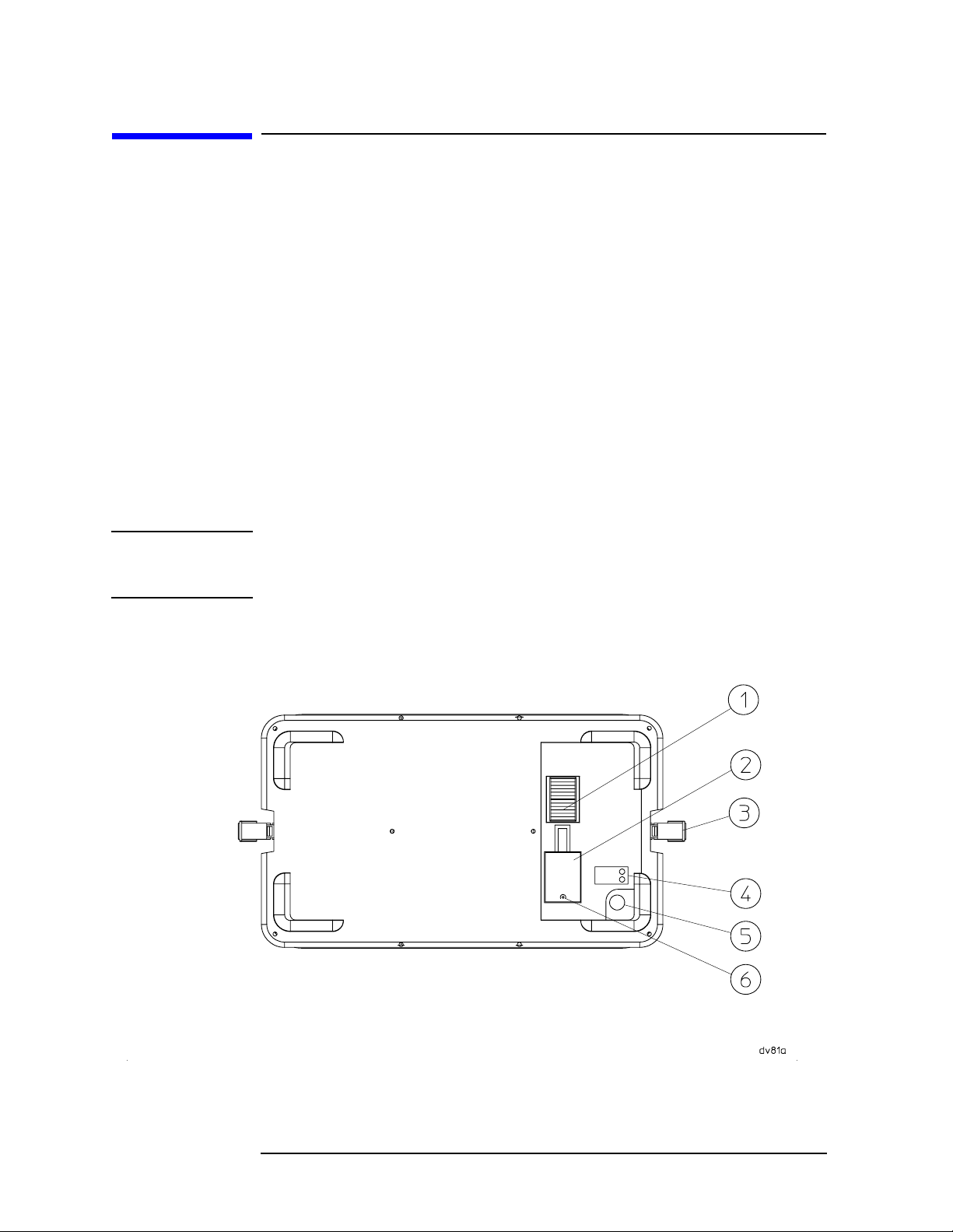
Panel Description
The battery pack has gold plated electrical contacts (1). A protective
rubber safety boot (2) is attached to protect the contacts when the
battery pack is not installed. A charging connector (5) is provided for
attachment of the charger power supply. Adjacent to the charging
connector are two LED indicator lights (4) to give visual information of
the charging status. The latches (3) on each side of the battery pack are
for attaching the battery pack to the spectrum analyzer. There is a hole
(6) provided for the rubber safety boot plug to hold the boot in place
when the battery pack is attached to the spectrum analyzer.
CAUTION The battery pack is NOT water resistant. It must be protected from
liquids and other contaminants which could be spilled on the connector
face.
Figure 1-1 Battery Pack Description
8 Chapter 1
Page 9
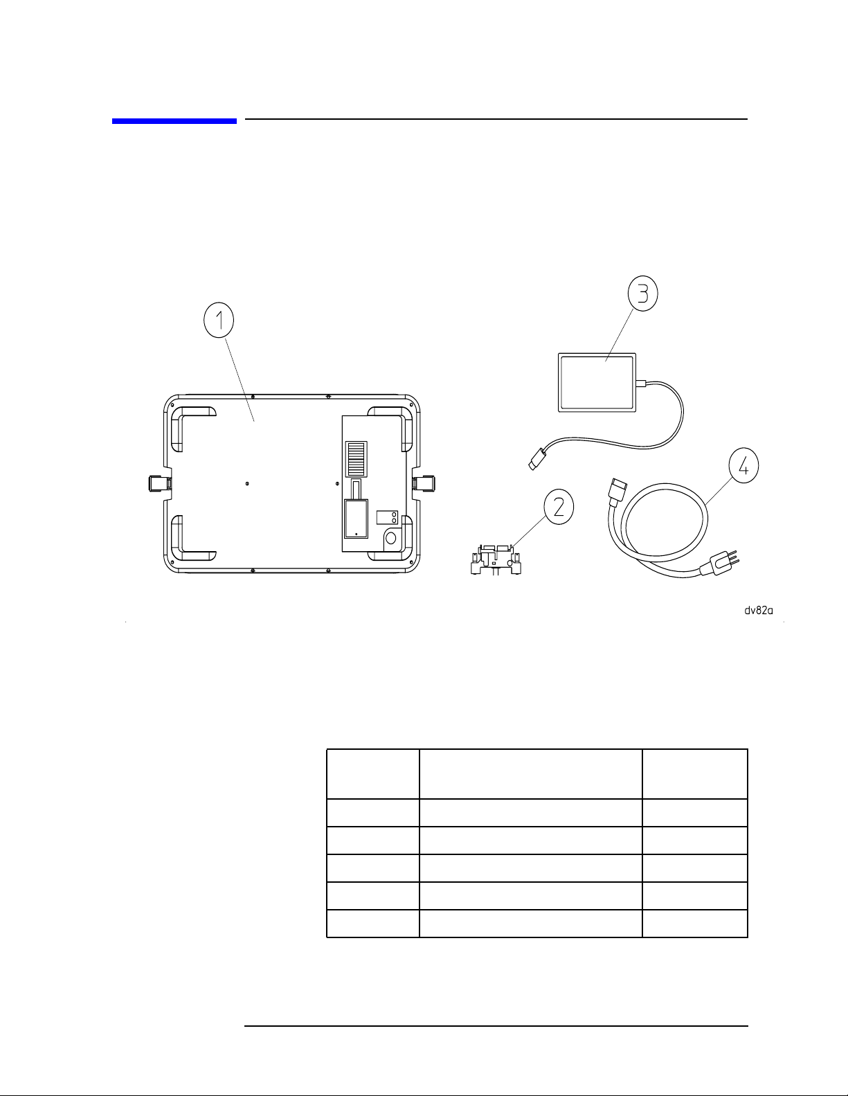
Initial Inspection
You should receive the following:
Figure 1-2 HP E1779A Battery Pack Components
Preparing for Use
Initial Inspection
Number Description
1 Battery Pack None
2 dc Adapter E4401-60025
3 Charger Power Supply E1779-60002
4 ac Line Cord See Table 1-1
User’s Guide E1779-90013
Chapter 1 9
HP Part
Number
Page 10

Preparing for Use
Initial Inspection
Power Cable
The battery pack charger power supply is equipped with a three-wire
power cable, in accordance with international safety standards. When
connected to an appropriate power line outlet, this cable grounds the
charger power supply case.
WARNING F ailure to ground the charger power supply properly can result
in personal injury. Insert the main power cable plug only into a
socket outlet that has a protective earth contact. DO NOT
defeat the earth-grounding protection by using an extension
cable, power cable, or autotransformer without a protective
ground conductor.
If you are using an autotransformer, make sure its common
terminal is connected to the protective earth contact of the
power source outlet socket.
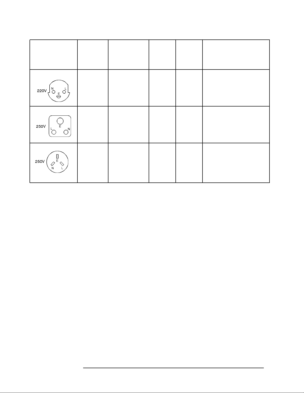
Various power cables are available to connect the charger power supply
to the types of ac power outlets unique to specific geographic areas. You
will receive the cable appropriate for the area to which the charger
power supply is originally shipped. You can order additional ac power
cables for use in different areas. The following table lists the available
ac power cables, illustrates the plug configurations, and identifies the
geographic area in which each cable is appropriate.
10 Chapter 1
Page 11
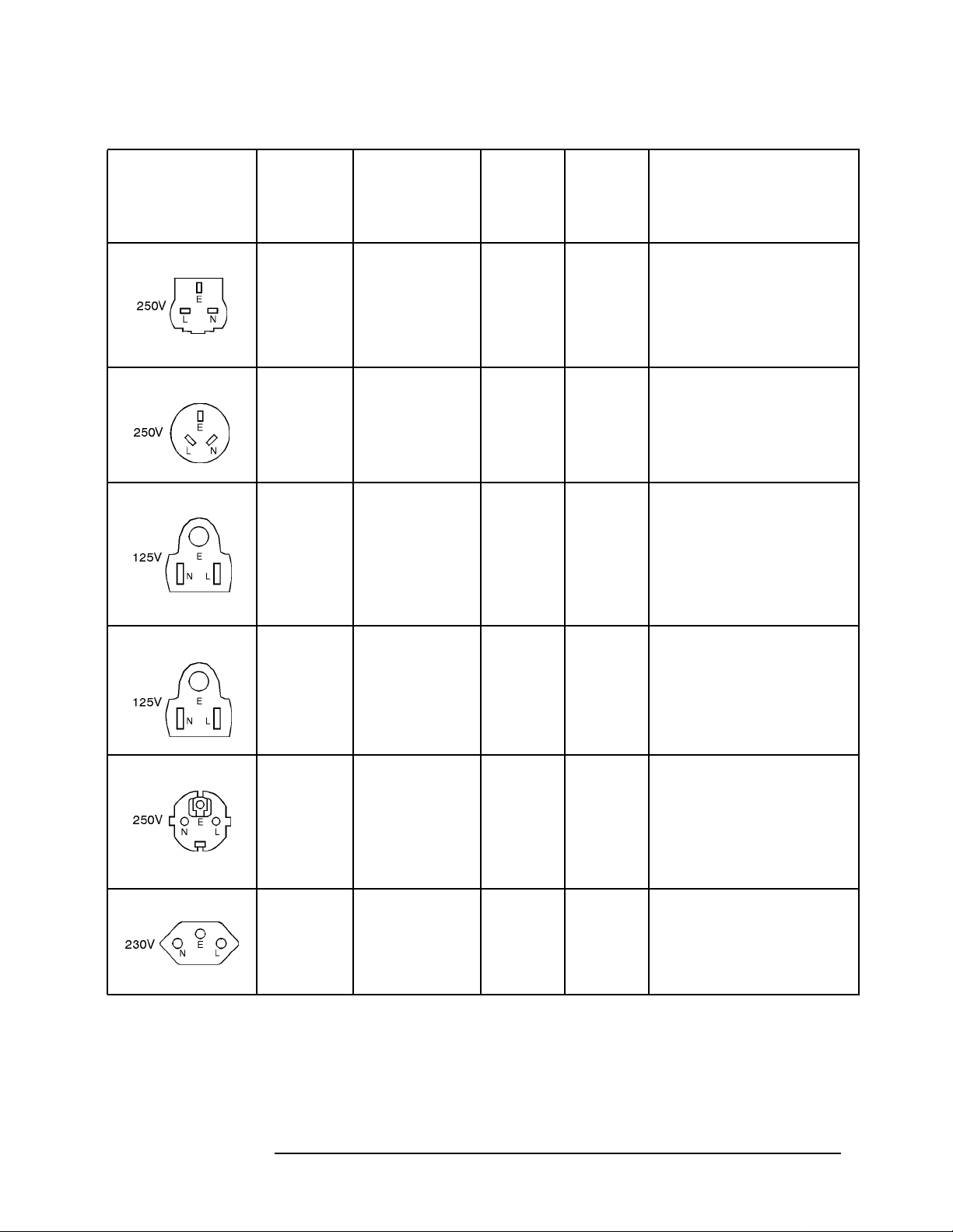
Table 1-1 Power Cables
Preparing for Use
Initial Inspection
Plug Type
a
HP
Cable
Part
Number
8120-1351
8120-1703
8120-1369
8120-0696
8120-1378
8120-1521
b
Plug
Description
Straight
BS 1363A
90˚
Straight
AS 3112
90˚
Straight
NEMA 5-15P
90˚
Length
cm (in.)
229 (90)
229 (90)
210 (79)
200 (78)
203 (80)
203 (80)
Cable
Color
Mint
Gray
Mint
Gray
Gray
Gray
Jade
Gray
Jade
Gray
For Use in Country
Option 900
United Kingdom, Hong
Kong, Cyprus, Nigeria,
Singapore, Zimbabwe
Option 901
Argentina, Australia, New
Zealand, Mainland China
Option 903
United States, Canada,
Brazil, Colombia, Mexico,
Philippines, Saudi
Arabia, Taiwan
8120-4753
8120-4754
8120-1689
8120-1692
8120-2104
8120-2296
Straight
NEMA 5-15P
90˚
Straight
CEE 7/VII
90˚
Straight
SEV Type 12
90˚
229 (90)
229 (90)
200 (78)
200 (78)
200 (78)
200 (78)
Gray
Gray
Mint
Gray
Mint
Gray
Gray
Gray
Option 918
Japan
Option 902
Continental Europe,
Central African Republic,
United Arab Republic
Option 906
Switzerland
Chapter 1 11
Page 12
Preparing for Use
Initial Inspection
HP
Plug Type
a
Cable
Part
Description
Plug
b
Length
cm (in.)
Cable
Color
For Use in Country
Number
8120-2956
8120-2957
8120-4211
8120-4600
Straight
SR 107-2-D
90˚
Straight
IEC 83-B1
90˚
200 (78)
200 (78)
200 (78)
200 (78)
Gray
Gray
Mint
Gray
Mint
Option 912
Denmark
Option 917
South Africa, India
Gray
8120-5182
8120-5181
Straight
SI 32
90˚
200 (78)
200 (78)
Jade
Gray
Jade
Option 919
Israel
Gray
a. E = earth ground, L = line, and N = neutral.
b. Plug identifier numbers describe the plug only. The HP part number is for the com-
plete cable assembly.
12 Chapter 1
Page 13

2 Installation and Operation
This chapter provides the information needed to charge, install, and
operate the HP E1779A battery pack.
13
Page 14

Installation and Operation
Battery Charging Procedure
Battery Charging Procedure
WARNING This is a Safety Class 1 Product when the battery is being
charged and is provided with a protective earthing ground
incorporated in the power cord. The mains plug shall only be
inserted in a socket outlet provided with a protective earth
contact. Any interruption of the protective conductor inside or
outside of the product is likely to make the product dangerous.
Intentional interruption is prohibited.
CAUTION This product is designed for use in Installation Category II and
Pollution Degree 2 per IEC 1010 and 664 respectively when being
charged with the approved ac to dc supply.
Connect the ac line to the charger power supply so that the detachable
power cord is readily identifiable and is easily reached by the operator.
The detachable power cord is the disconnection device. It disconnects
the charger power supply from the ac line. Alternatively, an externally
installed switch or circuit breaker (which is readily identifiable and is
easily reached by the operator) may be used as a disconnecting device.
Refer to Figure 2-1.
1. Remove the battery pack (1) from the instrument.
2. Plug the charger power supply (2) into the battery pack.
3. Connect the ac line cord (3) to the charger power supply and to the ac
line.
When the battery pack begins its charging cycle the red LED (5) will
start flashing. The red LED will then become a solid red light. When
the battery pack is fully charged, the green LED (4) will be lit.
NOTE Both LEDs will be lit if the internal temperature of the battery pack is
above 55 °C or below 10 °C.
Continuing to charge the battery pack after the green LED is lit will not
damage the unit. It will continue to charge in the trickle charge mode.
CAUTION Do not use any charger power supply other than that supplied with the
battery pack.
14 Chapter 2
Page 15

Installation and Operation
Battery Charging Procedure
NOTE There is a 6 hour charge time for the initial battery charge, and for
charging a fully depleted battery at room temperature. Charging the
battery at elevated temperatures will increase the charge time.
Occasionally the battery should be fully discharged prior to charging.
This will prevent degradation of battery capacity due to the memory
effects exhibited by nickel cadmium batteries.
Figure 2-1 Charging the Battery
Chapter 2 15
Page 16

Installation and Operation
Installing the Battery Pack
Installing the Battery Pack
WARNING This battery pack cannot be plugged into HP E4411A analyzers
with a serial number of US3736xxxx or below. The mating
screws are keyed to ensure that this is not possible. Overriding
the keyed safety feature could be dangerous.
NOTE Analyzers with a serial number of US3736xxxx or below require the
installation of Option R12 before the battery pack will operate.
NOTE Remove the spectrum analyzers ac connector (power cord) prior to
installing the battery.
CAUTION V entilation Requirements: When installing the product in a cabinet, the
convection into and out of the product must not be restricted. The
ambient temperature (outside the cabinet) must be less than the
maximum operating temperature of the product by 4 °C for every
100 watts dissipated in the cabinet.
There is no need to make a wire connection when installing the battery
pack. The dc contacts on the battery pack press against the contacts of a
dc adapter which plugs into the 12 Vdc input connector on the analyzer.
The battery pack is installed by attaching the latches on each side of
the battery pack to the analyzer.
Install the product according to the enclosure protection code IP 32.
There is protection against the entrance of solid foreign objects that are
greater than 2.5 mm in diameter and water that is dripping at an angle
of less than 15 degrees.
NOTE The dc connector system is designed to ensure very little power loss so
that all necessary power is supplied to the analyzer. Right angle
connectors are required for rear panel connections when the battery
pack is attached.
16 Chapter 2
Page 17

Installation Procedure
Use the following procedure to install the battery pack to your
spectrum analyzer:
1. Remove the power cord from the analyzer.
2. Attach the dc adapter (2) to the rear panel of the analyzer. The
adapter has no polarity. Tighten the two screws.
3. Uncover the battery dc contacts by securing the safety boot in its
open position.
4. Attach the battery pack (3) to the back of the analyzer. Battery pack
contacts should align with the dc adapter.
5. Fasten the latches (4) on each side of the battery pack to the
spectrum analyzer. Turn the analyzer on and begin dc operation.
Figure 2-2 Battery Pack Installation
Installation and Operation
Installing the Battery Pack
Chapter 2 17
Page 18

Installation and Operation
Operation
Operation
WARNING Shorting the battery pack contacts will result is unrepairable
damage to the contacts and internal circuit. There is also the
danger of burns. Use the safety boot to cover the contacts any
time the battery pack is removed from the instrument.
WARNING The power cord must not be installed with the battery pack in
place.
WARNING The charger power supply must not be connected to the battery
pack when the battery pack is attached to the analyzer.
An HP ESA spectrum analyzer will operate with the same functionality
on dc power as it will on ac power except that the line trigger will not
function.
Basic Operation Check
The only basic operation checks for the battery pack are whether or not
it takes a charge, and whether or not the instrument powers on when
the battery pack is installed.
The battery pack has no operational specifications and is therefore not
subject to periodic calibration.
WARNING No serviceable parts inside. Do not disassemble.
18 Chapter 2
Page 19

3 Troubleshooting
This chapter provides information on how to troubleshoot your battery
pack.
19
Page 20

T roubleshooting
Tr oubleshooting
Troubleshooting
Your battery pack is built to provide dependable service during the
service life of the ni-cad batteries. However, if you experience a
problem, desire additional information, or wish to order parts,
Hewlett-Packard’ s worldwide sales and service organization is ready to
provide the support you need.
Basic Troubleshooting
If the battery pack does not work, follow these steps to determine the
cause and resolve the problem:
1. Make sure the analyzer works with ac power. If it does not, follow
the troubleshooting procedures in the spectrum analyzer user’s
guide.
2. If the spectrum analyzer operates on ac power, but not on dc power:
a. Check all of your connections. Is the dc adapter firmly in place?
Are the battery contacts aligned with the dc adapter?
b. Check the 30 A 32 Vdc fuse on the spectrum analyzer. Replace it
if it is blown. (Refer to Figure 3-2.)
3. Make sure that the battery pack is taking a charge from the charger
power supply. Follow the recharging procedure. Usually batteries
near the end of their life will still take a partial charge. If there is no
charge at all, you may need to replace the charger power supply or
the battery pack.
If you are not sure whether the cause of failure is the battery pack or
the charger power supply, follow the troubleshooting procedures
below, or send your battery pack and charger power supply to a
service center for diagnosis. Sending both the battery pack and the
charger power supply will ensure a complete analysis.
Troubleshooting the Battery Pack and the 24 Vdc
Charger Power Supply
Follow these steps to determine whether the battery pack or the
charger power supply is defective:
1. Check the charger power supply for 24 Vdc ±10 % by measuring its
voltage under load with an autoranging multimeter.
Refer to Figure 3-1 when performing the following steps:
20 Chapter 3
Page 21

Figure 3-1 Charger Supply Load Test Fixture
Troubleshooting
Troubleshooting
a. Strip the ends of two four-inch pieces of 16 AWG wire, one white
and one black.
b. Solder one end of the black wire to the negative terminal (center
solder lug) of a 2.5 mm male barrel jack (HP part number
1252-5866), and one end of the white wire to the positive terminal
(refer to Figure 3-1). Leave the third terminal of the male barrel
connector unconnected.
c. Plug the two wires from the barrel jack into the terminals of a
dual banana plug (HP part number 1251-0005) and plug this into
the multimeter.
d. Solder together 3 pairs of 20 Ω 20 W resistors (HP part number
0811-1656) in parallel to create the 13.3 Ω 120 W equivalent
circuit shown in Figure 3-1.
e. Connect this 13.3 Ω circuit to the lead terminals of a second dual
banana plug and plug this into the first dual banana plug.
f. Plug the charger power supply’s barrel plug into the barrel jack.
Chapter 3 21
Page 22

T roubleshooting
Tr oubleshooting
• If a voltage of 24 Vdc ±10 % is not present, it indicates that the
charger power supply is defective. Avoid leaving the charger
power supply connected for more than 1 or 2 minutes since the
resistors get very hot.
WARNING The resistors will get very hot. Handle with care.
2. If the correct charger power supply voltage (24 Vdc ±10 %) is
present, plug the charger power supply into the battery pack and
ensure that the red LED flashes, then remains on.
NOTE The red LED should turn on and the battery should charge initially
even if the battery pack is fully charged.
If the green LED turns on immediately, this indicates a defective
battery pack. If the red LED continues blinking, this indicates that
the battery pack voltage is below 16 Vdc. The battery will charge in
trickle mode until this condition no longer exists. If this condition
continues indefinitely, this also indicates a defective battery pack.
3. If the red LED flashed and then remained on, as expected, confirm
that the battery charges correctly by probing the battery pack
contacts with the multimeter. The charger power supply will start
charging the battery initially even if the battery is fully charged. The
voltage should gradually increase, indicating that the battery is
charging. If the voltage does not increase by several hundredths of a
volt over a period of 1 to 2 minutes, this indicates that the battery is
not charging properly. Y ou may wish to retry the test by unplugging
and then plugging in the charger power supply again. If the battery
still does not charge, unplug the charger power supply and replace it
with a known good charger power supply and repeat the test. If the
battery charges, this indicates that the original charger power
supply is defective. If the battery does not charge with a new
charger power supply, this indicates that the battery pack is
defective.
NOTE Both LEDs will be lit if the internal temperature of the battery pack is
above 55 °C or below 10 °C.
4. If all three of these tests pass, it indicates that the charger power
supply and the battery pack are both working.
NOTE Defective battery packs should be discarded according to individual
country’s requirements.
22 Chapter 3
Page 23

Figure 3-2 DC Adapter Plug and Fuse
Troubleshooting
Troubleshooting
Cleaning
The battery pack contacts will provide good service over the life of the
assembly. Should they become contaminated, clean by wiping gently
with a clean dry cloth.
Chapter 3 23
Page 24

T roubleshooting
Tr oubleshooting
Replacement
When run time is unacceptable, replace the battery pack. The battery
pack cannot be opened for repair. The only replaceable parts are the
charger power supply, the dc adapter, the power cord, and the safety
boot.
Latch Replacement
If the latch (1) to the battery pack needs to be replaced, order HP part
number 1390-1061. Remove the two screws (HP part number
0515-0433) holding the latch in place, and attach the new latch.
Safety Boot Replacement
To replace the safety boot (2), order part number E4401-40022 from
Hewlett-Packard. Cut the remaining parts of the old safety boot from
the battery pack. Insert the feet of the new safety boot into the holes
provided.
Figure 3-3 Replaceable Parts
24 Chapter 3
Page 25

4 Characteristics
This chapter contains information about the characteristic operating
parameters of the HP E1779A battery source. Characteristics provide
useful but non-warranted information about the functions and
performance of the battery pack.
25
Page 26

Characteristics
Characteristics
Characteristics
NOTE All characteristics are at 25 °C and at the beginning of battery life.
Output Voltage 19.2 volts
Capacity 105 watt hours
Service Life 500 Cycles to 80% Initial Capacity
(at 25 °C)
Typical Runtime
Runtime is typically between 60 minutes and 90 minutes depending
upon options installed.
Table 4-1
Chemistry Nickel Cadmium
Charge Time
Charging Temperature
Discharging Temperature
Storage Temperature
Maximum Relative Humidity
1 Charge time may exceed 6 hours at temperatures above 25 °C.
2 Refer to the following graphs for temperature impact on battery performance and service
life.
3 For temperatures up to 31°C. Maximum relative humidity will decrease linearly to 50% at
40 °C.
CAUTION Battery service life degrades rapidly at temperatures above 40 °C. This
6 Hours
10° to 40 °C
0° to 55 °C
−30° to 55 °C
80%
1
2
2
2
3
effect can be minimized if it is held for only a short period of time at the
high temperature, such as during discharge. Prolonged storage at only
40 °C could reduce the service life to 45% of its room temperature life.
The service life is reduced to 20% at 50 °C.
26 Chapter 4
Page 27

Figure 4-1 Battery Charge Capacity vs Temperature
Characteristics
Characteristics
Figure 4-2 Battery Cycle Life vs Temperature
Chapter 4 27
Page 28

Characteristics
Characteristics
Figure 4-3 Battery Charge Acceptance versus Temperature
Table 4-2
Physical Characteristics
Weight 4.8-kg (10.6-lbs)
Height 217-mm (8.54-in)
Width 373-mm (14.69-in)
Depth 68-mm (2.68-in), 44-mm (1.73-in) added
to instrument depth
Table 4-3
Supply Requirements
Nominal Input Voltage 100/115/230/240 Volts
Input Voltage Range 90-254 Volts
Nominal Input Frequency 50/60 Hz
Input Frequency Range 47-66 Hz
Input Power 60 Watts Maximum
Output Voltage 24 Vdc
28 Chapter 4
Page 29

Environmental Conditions
Portable
Altitude up to 4,572 meters (15,000 feet)
This product, when being recharged with the approved ac to dc supply, is designed
for use in INSTALLATION CATEGORY II and POLLUTION DEGREE 2, per IEC
1010 and 664 respectively.
Characteristics
Characteristics
Chapter 4 29
Page 30

Characteristics
Regulatory Information
Regulatory Information
CAUTION This product is designed for use in Installation Category II and
Pollution Degree 2 per IEC 1010 and 664 respectively.
NOTE This product has been designed and tested in accordance with IEC
Publication 1010, Safety Requirements for Electronic Measuring
Apparatus, and has been supplied in a safe condition. The instruction
documentation contains information and warnings which must be
followed by the user to ensure safe operation and to maintain the
product in a safe condition.
The CE mark is a registered trademark of the European Community.
The CSA mark is the Canadian Standards Association safety mark.
ISM 1-A This is a symbol of an Industrial Scientific and Medical Group 1 Class A
product. (CISPR Pub. 11, Clause 4)
This is a symbol to alert you that you must dispose of a material properly
according to your country’s requirements and not just throw it into the
trash.
RBRC is a trademark of the Rechargeable Battery Recycling Corporation.
30 Chapter 4
Page 31

Figure 4-4
Characteristics
Regulatory Information
Chapter 4 31
Page 32

Characteristics
Regulatory Information
32 Chapter 4
Page 33

5 Disposal and Service
This chapter provides information on disposing of your battery pack
when its service life is gone, and on contacting Hewlett-Packard for
service.
33
Page 34

Disposal and Service
Disposal
Disposal
Battery Disposal
When the batteries are exhausted and/or ready for disposal, dispose of
them according to your country’s requirements. W ithin the US, you ma y
contact RBRC for disposal.
34 Chapter 5
Page 35

Disposal and Service
Disposal
RBRC
The RBRC Seal on the nickel-cadmium battery pack indicates that
Hewlett-Packard is voluntarily participating in an industry program to
collect and recycle these battery packs at the end of their useful life,
when taken out of service within the United States. The RBRC program
provides a convenient alternative to placing spent nickel-cadmium
battery packs into the trash or municipal waste stream, which is illegal
in some areas.
Hewlett-Packard’s arrangement with RBRC makes it easy for you to
drop off your spent battery pack at local retailers of replacement
nickel-cadmium batteries, or authorized Hewlett-Packard product
service centers. You may contact your local recycling center for
information on where to return the spent battery pack. Please call
1-800-BATTERY for information on NiCD battery recycling in your
area. Hewlett-Packard’s involvement in this program is part of its
commitment to protecting our environment and conserving natural
resources.
RBRC is a trademark of the Rechargeable Battery Recycling
Corporation.
Chapter 5 35
Page 36

Disposal and Service
Contacting Hewlett-Packard
Contacting Hewlett-Packard
If you have a problem with your battery pack, check the troubleshooting
steps earlier in Chapter 3, or return the battery pack to
Hewlett-Packard.
Battery Pack Serial Numbers
Hewlett-Packard makes frequent improvements to its products to
enhance performance, usability, or reliability. Hewlett-Packard service
personnel have access to complete records of design changes to each
type of product, based on the serial number and option designation.
Whenever you contact Hewlett-Packard about your battery pack, have
the complete serial number available. This will ensure that you obtain
accurate service information.
The serial number label is attached near the dc output connector on the
battery pack.
The serial number has two parts: the prefix (two letters and the first
four numbers), and the suffix (the last four numbers). Refer to Figure
5-1.
Figure 5-1 Example Serial Number
The two letters identify the country in which the battery pack was
manufactured. The four numbers of the prefix are a code identifying the
date of the last major design change incorporated into the battery pack.
The four digit suffix is a sequential number, and coupled with the
prefix, provides a unique identification for each battery pack produced.
Whenever you list the serial number or refer to it in obtaining
information about the battery pack, be sure to use the complete
number, including the full prefix and suffix.
36 Chapter 5
Page 37

Disposal and Service
Contacting Hewlett-Packard
Calling HP Sales and Service Offices
Hewlett-Packard’ s sales and service offices are located around the world
to provide complete support for your battery pack. To obtain servicing
information or to order replacement parts, contact the nearest
Hewlett-Packard Sales and Service office listed in Table 5-1. In any
correspondence or telephone conversations, refer to the battery pack by
its model number and full serial number. With this information, the HP
representative can quickly determine whether your battery pack is still
within its warranty period.
How to Order Parts
To order an assembly or part, quote the Hewlett-Packard part number
and indicate the quantity required.
If you do not have the part number, include the following information
with the order:
• Model number
• Serial number
• Description of where the part is located, what it looks like, and its
function (if known).
• Quantity
Parts can be ordered by addressing the order to the nearest
Hewlett-Packard office. Customers within the USA can also use either
the direct mail-order system, or the direct phone-order system
described below. The direct phone-order system has a toll-free phone
number available.
Direct Phone-Order System
Within the USA, Hewlett-Packard can supply parts through a direct
mail-order system. Advantages of using the system are as follows:
• Direct ordering and shipment from Hewlett-Packard.
• No maximum or minimum on any mail order. (There is a minimum
order amount for parts ordered through a local HP office when the
orders require billing and invoicing.)
• Prepaid transportation. (There is a small handling charge for each
order.)
• No invoices.
Chapter 5 37
Page 38

Disposal and Service
Contacting Hewlett-Packard
To provide these advantages, a check or money order must accompany
each order. Mail-order forms and specific ordering information are
available through your local HP office.
Direct Phone-Order System
Within the USA, a phone order system is available for regular and
hotline replacement parts service. A toll-free phone number is
available, and Mastercard and Visa are accepted. Outside the USA,
contact your local sales and service office.
Regular and Hotline Orders
The toll-free phone number, (800) 227-8164, is available Monday
through Friday, 6 a.m. to 5 p.m. (Pacific time). Regular orders have a
four-day delivery time. After hours, a fax number is available, (800)
329-4470.
38 Chapter 5
Page 39

Table 5-1 Hewlett-Packard Sales and Service Offices
UNITED STATES
Instrument Support Center
Hewlett-Packard Company
(800) 403-0801
EUROPEAN FIELD OPERATIONS
Headquarters
Hewlett-Packard S.A.
150, Route du Nant-d’Avril
1217 Meyrin 2/ Geneva
Switzerland
(41 22) 780.8111
Great Britain
Hewlett-Packard Ltd.
Eskdale Road, Winnersh Triangle
Wokingham, Berkshire RG41 5DZ
England
(44 734) 696622
France
Hewlett-Packard France
1 Avenue Du Canada
Zone D’Activite De Courtaboeuf
F-91947 Les Ulis Cedex
France
(33 1) 69 82 60 60
INTERCON FIELD OPERATIONS
Headquarters
Hewlett-Packard Company
3495 Deer Creek Rd.
Palo Alto, CA 94304-1316
USA
(415) 857-5027
Australia
Hewlett-Packard Australia Ltd.
31-41 Joseph Street
Blackburn, Victoria 3130
(61 3) 895-2895
Disposal and Service
Contacting Hewlett-Packard
Germany
Hewlett-Packard GmbH
Hewlett-Packard Strasse
61352 Bad Homburg v.d.H
Germany
(49 6172) 16-0
Canada
Hewlett-Packard (Canada) Ltd.
17500 South Service Road
Trans-Canada Highway
Kirkland, Quebec H9J 2X8
Canada
(514) 697-4232
Japan
Hewlett-Packard Japan, Ltd.
9-1 Takakura-Cho, Hachioji
Tokyo 192, Japan
(81 426) 60-2111
China
China Hewlett-Packard Co.
38 Bei San Huan X1 Road
Shuang Yu Shu
Hai Dian District
Beijing, China
(86 1) 256-6888
Singapore
Hewlett-Packard Singapore (Pte.) Ltd.
150 Beach Road
#29-00 Gateway West
Singapore 0718
(65) 291-9088
Taiwan
Hewlett-Packard Taiwan
8th Floor, H-P Building
337 Fu Hsing North Road
Taipei, Taiwan
(886 2) 712-0404
Chapter 5 39
 Loading...