

Agilent 75000 SERIES C
E1472A 50 Ohm RF Multiplexer
E1473A 50 Ohm RF Multiplexer Expander
E1474A 75 Ohm RF Multiplexer
E1475A 75 Ohm RF Multiplexer Expander
Service Manual
Copyright© Agilent Technologies, Inc., 1996 - 2006
*E1472-90011*
E1472-90011
Manual Part Number: E1472 -90011 Printe d: Augus t 2006 Edition 2 Rev 2
Printed in Malaysia E0806


Certification
Agilent Technologies certifies that this product met its published specifications a t the time o f shipment from the factory. Agilent
Technologie s further certifies tha t its calibr ation measure ments are tracea ble to the Unit ed States Nati onal Institu te of Stand ards and
Technology (formerly Nati onal Bureau of Standards), to the ex tent allowed by that organizat ion’s calibrat ion facility , and to the calibration
facilities of other International Standards Organization members.
Warranty
This Agilent Technologies product is warranted against defects in materials and workmanship for a period of one (1) year from date of
shipment. Duration and conditions of warranty for this product may be superseded when the product is integrated into (becomes a part
of) other Agilent products. During the warranty period, Agilent Technologies will, at its option, eithe r repair or r ep la ce p ro d uc ts wh ich
prove to be def ec t ive.
For warrant y service or repair, t hi s product m ust be retu rned to a service facility designated by Agilent Technologies. Buyer shall prepay
shipping charges to Agilent and Agil ent shall pay shipping charge s to return the product to B uyer. However, Buye r sha l l pay all shipping
charges, duties, and taxes for product s re t urned to Agil ent fr om another cou nt ry.
Agilent warrants that its software and firmware designated by Agilent for use with a product will execute its programming instruc tions
when properly installed on that product. Agilent does not warrant that the operation of the product, or software, or firmware will be
uninterrupt ed or error free .
Limitation Of Warranty
The foregoi ng warranty shall not apply to defects res ul ting from improper or in adequate maintenanc e by Buyer, Buyer-supplied products
or interfacing, unauthori zed modific ation or mis use, operat ion outsid e of the envi ronmenta l specific ations for the prod uct, or improper site
preparation or maintenance.
The design and implementation of any circuit on this product is the sole responsibility of the Buyer. Agilent does not warrant the Bu yer ’s
circuitry or malfunctions of Agilent products that result from the Buyer’s circuitry. In addition, Agilent does not warrant any damage that
occurs as a r es ul t of th e B uyer’s circuit or any defects tha t res ul t fro m Bu yer -s upplied products.
NO OTHER WARRANTY IS EXPRESSED OR IMPLIED. Agilen t SPECIFICALLY DISCL AIMS THE IMPLIED WARRANTI ES
OF MERCHANTABILITY AND FITNESS FOR A PARTICULAR PURPOSE.
Exclusive Remedies
THE REMEDIES PROVIDED HEREIN ARE BUYER’S SOLE AND EXCLUS IVE REMEDIES. Agilent SHALL NOT BE LIABLE
FOR ANY DIRECT, INDIRECT, SPECIAL, INCIDENTAL, OR CONSEQUENTIAL DAMAGES, WHETHER BASED ON CONTRACT, TORT, OR ANY OTHER LEGAL THEORY.
Notice
The information contained in this document is subject to change without notice. Agilent Technologies MAKES NO WARRANTY OF
ANY KIND WITH REGARD TO THIS MATERIAL, INCL UDING, BUT NOT LIMITED TO, THE IMPLIED WARRANTIES OF
MERCHANTABILITY AND FITNESS FOR A PARTICULAR PURPOSE. Agilent shall not be liable for errors contained herein or for
incidental or consequential damages in connection with the furnishing, performance or use of this material. This document contains
proprietar y information whi ch is protected by copy right. All rights are reserved. No part of this docume nt may be phot ocopied, rep roduced,
or translat ed t o anot her l anguag e wi thout the prior w ritten consent of Agilent Technologies, Inc. Agilent assumes no responsibility f or the
use or reliability of its software on equipment that is not furnished by Agilent.
U.S. Government Restricted Rights
The Software and Documentation have been developed entirely at private expense. They are delivered and licensed as "commercial
computer software" as defined in DFARS 252.227- 7013 (Oct 1988), DFARS 252.211-7015 (May 1991) or DFARS 252.227-7014 (Jun
1995), as a "com mercial item " as defined in FAR 2.101(a), or as "Restric ted computer software" as define d in FAR 52.227-19 (Jun 1987)(or
any equival ent age ncy reg ulati on or contra ct cl ause ), which eve r is appl icab le. You hav e only t hose r ight s provide d for suc h Software and
Documen ta t io n by t he applicabl e FA R or DF A R S cl ause or the Agilent standa rd sof tw a re agreement for the product i nvolved.
Agilent E1472A/73A/74A/75A 50W/75W RF Multiplexers/Expanders Module Service Manual
Copyright © 1996-2006 Agi l ent T e chnologies, Inc. All Righ ts R es er ved.
Edition 2 Rev 2
Agilent E1472A/73A/74A/75A 50W/75W RF Multiplexers /Ex panders Module Service Manual 1
Printing H is tory
The Printing History shown below lists all Editions and Updates of this manual and the printing date(s). The first printing of the manual
is Edition 1. The Editi on number incremen ts by 1 whenever the manua l is r ev is ed . Up dates, which are issue d bet wee n Ed itio n s, contain
replacement pages to correct the current Edition of the manual. Updates are numbered sequentially starting with Update 1. When a new
Edition is crea ted, it cont ains all the Upda te i nfor mat ion for the p revious Ed ition. E ach ne w E dition or U pdat e a lso incl udes a re vised copy
of this prin ti ng history p age. Man y pr oduct updat es or revis i ons do not require manual chan ges and, con versely, m anual corrections may
be done without accompanying product changes. Therefore, do not expect a one-to-one correspondence between product updates and
manual updates.
Edition 1 (P ar t Num ber E1472-90010). . . . . . . . . . . . . . . . . . . . . . . August 1992
Edition 2 (P ar t Num ber E1472-90011). . . . . . . . . . . . . . . . . . . . . . . . . May 1996
Edition 2 Rev 2 (Pa rt N um ber E1472-9001 1) . . . . . . . . . . . . . . . . . August 2006
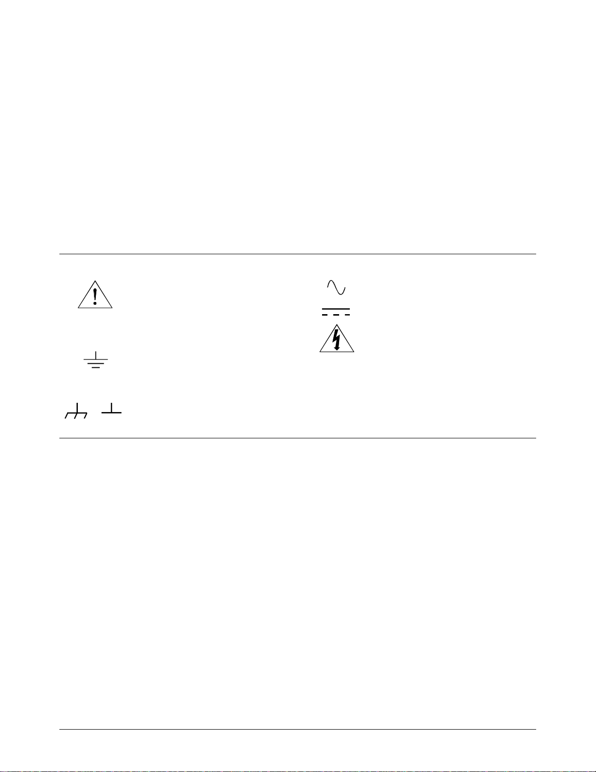
Safety Symbols
Instructi on manual sy mbol affixed to product.
Indic ates th a t the user must refer to th e manual for specific WARNING or CAUTION
informatio n to avoi d personal injury or damage to the pr oduct.
Alternating current (AC).
Direct current (DC).
Indicates t he field wir ing termina l that must
be connec ted to earth gr ound before op erating
the equipment—protects against electrical
shock in case of fault.
or
Frame or chassis ground terminal—typically
connects to the equipment’s metal frame.
WARNING
CAUTION
Indicate s ha zardous volta g e s.
Calls a tt e ntion to a procedur e, practice , or condition that could cause bodi l y i njury or death.
Calls attention to a proce dur e, pra ct i ce, or condition that could possibly cause damage to
equipme nt or pe rm anent loss of dat a.
WARNINGS
The following general safety precautions must be observed during all phases of operation, service, and repair of this product.
Failure to comply with these prec autions or w ith speci fic warnings elsewh er e in this manual vi ol at es safety stand ar d s of desig n ,
manufacture, and intended use of the product. Agilent Technologies assumes no liability for the customer’s failure to comply with
these re qu i rements.
Ground the equipment: For Safety Class 1 equipment (equipment having a protective earth terminal), an uninterruptible safety earth
ground must be provided from t he m ains power sour ce to the product i nput w iring termi nal s o r su ppl i ed power cable.
DO NOT operate the product in an explosiv e at mospher e or in the presence of flammable g ases or fume s.
For continued protection against fire, replace the line fuse(s) only with fuse(s) of the same voltage and current rating and type.
DO NOT use re pai r ed fuses or short -c i rc uited fuse hol der s.
Keep away fr om live circuit s: Ope ra t in g per sonnel must not remove equipment covers or shi el ds. Procedure s involving the re m oval of
covers or shields are for use by service-trained personnel only. Under certain conditions, dangerous voltages may exist even with the
equipmen t switch ed off. To avoid da ngerou s elec trica l shoc k, DO NOT perform proced ures invo lvin g cover or shield re mova l unless you
are qualified to do so.
DO NOT operate damaged equipment: Whenever it is pos sible that the safety protection feat ures built into this pro duct have been
impaired, either through physical damage, excessive moisture, or any other reason, REMOVE POWER and do not use the product until
safe oper at i on can be verified by service-tra ined pers onnel. If ne cessary, r et urn the product to an Agilent Technologies Sale s and Servi ce
Office for service and repair to ensure that safety features are maintained.
DO NOT serv ice or adjust al one: Do not at tempt inte rnal ser vice or adjus tment unles s anot her per son, ca pabl e of renderi ng first aid and
resuscitation, is present.
DO NOT substitute parts or modify equipm ent: Because of the danger of introducing additional hazards, do not install substitute parts
or perform any unauthorized modification to the product. Return the product to an Agilent Technologies Sales and Service Office for
service and repair to ensure that safety features are maintained.
2 Agilent E1472A/73A/74A/75A 50W/75W RF Multiplexers/Expanders Module Service Manual

DECLARATION OF CONFORMITY
According to ISO/IEC Guide 22 and CEN/CENELEC EN 45014
Manufacturer’s Name:
Agilent Technologies, Incorporated
Manufacturer’s Address: Measurement Product Generation Unit
815 14th ST. S.W.
Loveland, CO 80537 USA
Declares, that the product
Product Name:
Model Number:
50 Ohm RF Multiplexer and Expander
E1472A/E1473A
Product Options: This declaration covers all options of the above product(s).
Conforms with the following European Directives:
The product herewith complies with the requirements of the Low Voltage Directive 73/23/EEC and the EMC Directive 89/336/EEC
and carries the CE Marking accordingly
Conforms with the following product standards:
EMC Standard
IEC 61326-1:1997+A1:1998 / EN 61326-1:1997+A1:1998
CISPR 11:1997 +A1:1997 / EN 55011:1998
IEC 61000-4-2:1995+A1:1998 / EN 61000-4-2:1995
IEC 61000-4-3:1995 / EN 61000-4-3:1995
IEC 61000-4-4:1995 / EN 61000-4-4:1995
IEC 61000-4-5:1995 / EN 61000-4-5:1995
IEC 61000-4-6:1996 / EN 61000-4-6:1996
IEC 61000-4-11:1994 / EN 61000-4-11:1994
Limit
Group 1 Class A
4kV CD, 8kV AD
3 V/m, 80-1000 MHz
0.5kV signal lines, 1kV power lines
0.5 kV line-line, 1 kV line-ground
3V, 0.15-80 MHz
I cycle, 100%
[1]
Canada: ICES-001:1998
Australia/New Zealand: AS/NZS 2064.1
Safety
IEC 61010-1:1990+A1:1992+A2:1995 / EN 61010-1:1993+A2:1995
Canada: CSA C22.2 No. 1010.1:1992
UL 3111-1:1994
Supplemental Information:
[1]
The product was tested in a typical configuration with Agilent Technologies test systems.
September 5, 2000
Date Name
Quality Manager
Title
Authorized EU-representative: Agilent Technologies Deutschland GmbH, Herrenberger Straβe 130, D 71034 Böblingen, Germany
For further information, please contact your local Agilent Technologies sales office, agent or distributor.
Agilent E1472A/73A/74A/75A 50W/75W RF Multiplexers/Expanders Module Service Manual 3

DECLARATION OF CONFORMITY
According to ISO/IEC Guide 22 and CEN/CENELEC EN 45014
Manufacturer’s Name:
Agilent Technologies, Incorporated
Manufacturer’s Address: Measurement Product Generation Unit
815 14th ST. S.W.
Loveland, CO 80537 USA
Declares, that the product
Product Name:
Model Number:
75 Ohm RF Multiplexer and Expander
E1474A/E1475A
Product Options: This declaration covers all options of the above product(s).
Conforms with the following European Directives:
The product herewith complies with the requirements of the Low Voltage Directive 73/23/EEC and the EMC Directive 89/336/EEC
and carries the CE Marking accordingly
Conforms with the following product standards:
EMC Standard
IEC 61326-1:1997+A1:1998 / EN 61326-1:1997+A1:1998
CISPR 11:1997 +A1:1997 / EN 55011:1998
IEC 61000-4-2:1995+A1:1998 / EN 61000-4-2:1995
IEC 61000-4-3:1995 / EN 61000-4-3:1995
IEC 61000-4-4:1995 / EN 61000-4-4:1995
IEC 61000-4-5:1995 / EN 61000-4-5:1995
IEC 61000-4-6:1996 / EN 61000-4-6:1996
IEC 61000-4-11:1994 / EN 61000-4-11:1994
Limit
Group 1 Class A
4kV CD, 8kV AD
3 V/m, 80-1000 MHz
0.5kV signal lines, 1kV power lines
0.5 kV line-line, 1 kV line-ground
3V, 0.15-80 MHz
I cycle, 100%
[1]
Canada: ICES-001:1998
Australia/New Zealand: AS/NZS 2064.1
Safety
IEC 61010-1:1990+A1:1992+A2:1995 / EN 61010-1:1993+A2:1995
Canada: CSA C22.2 No. 1010.1:1992
UL 3111-1:1994
Supplemental Information:
[1]
The product was tested in a typical configuration with Agilent Technologies test systems.
September 5, 2000
Date Name
Quality Manager
Title
Authorized EU-representative: Agilent Technologies Deutschland GmbH, Herrenberger Straβe 130, D 71034 Böblingen, Germany
For further information, please contact your local Agilent Technologies sales office, agent or distributor.
4 Agilent E1472A/73A/74A/75A 50W/75W RF Multiplexers/Expanders Module Service Manual
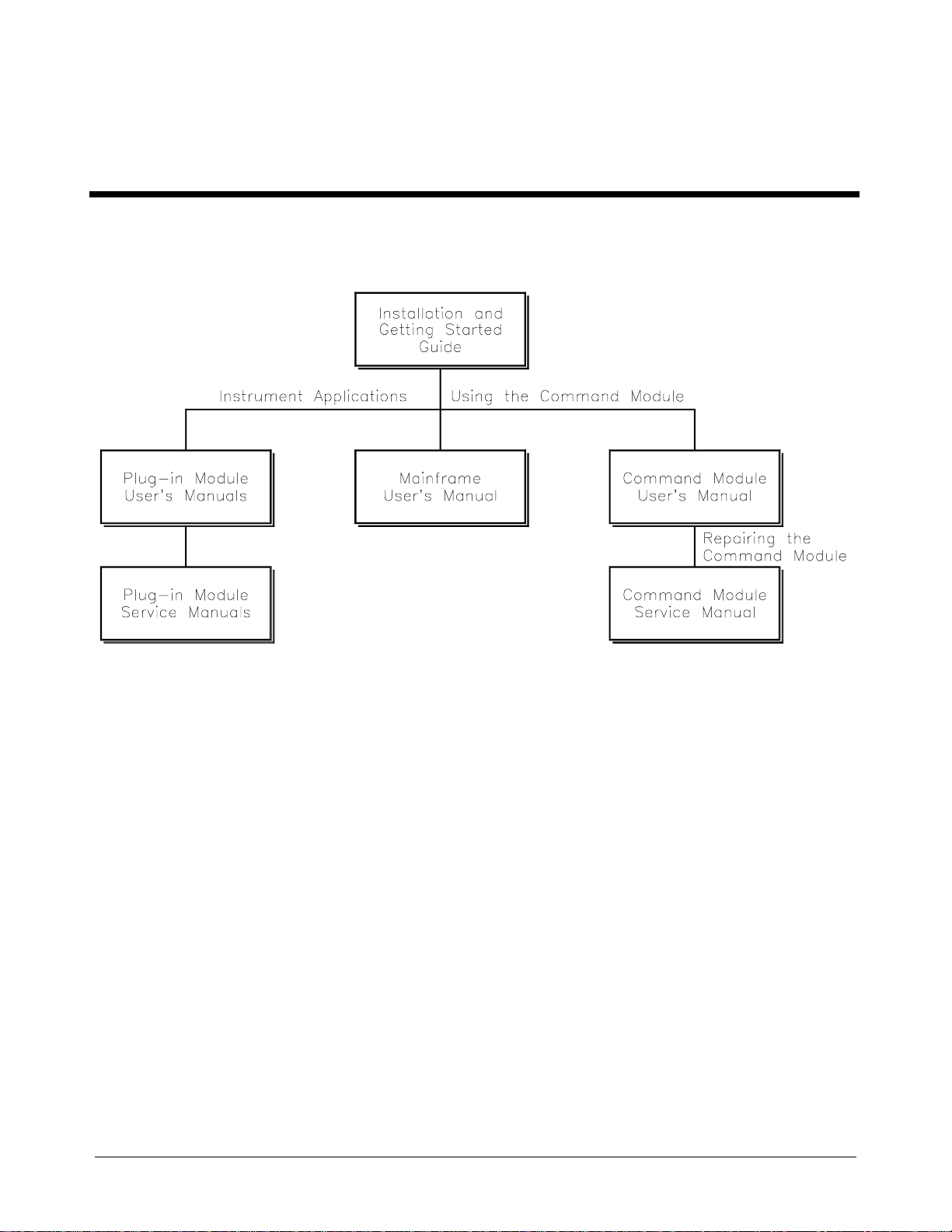
Agilent 75000 Series C Service Documentation
Suggested Sequence to Use Manuals
Manual Descriptions
Series C Installation and Getting Started Guide. This manual contains step -by-step instructions for all aspects of
plug-in module, mainframe , an d co mm a nd m odule installat ion . T hi s gu ide also contains introductory prog ra mm i ng
information and examples.
Command Module User’s Manual. This manual conta i ns programming information for the Command Module , a nd
general programming info rm at io n for instruments ins talled in the mainframe.
Mainframe User’s Manual. This manual contains installation information to prepare the mainframe for use and shows
how to install plug-in modules.
Plug-In Module User’s Manuals. These manuals con ta in plug-in module pro gramming and configuration in form ation.
Each manua l c ont a ins programming e xa mples and a complete SCPI comm a nd reference for t he plug-in module.
Plug-In Module Service Manuals. These manuals contain plug-in module service information. Each manual contains
information for exchangin g the m odul e and/or orderi ng re placeable parts. Depending on the module, information and
procedure s fo r func t ional verifica ti on, ope ra ti on ve rification, pe rformance veri fication, adj us tment, troublesh oot ing , a nd
repair are also provided.
Agilent E1472A/73A/74A/75A Service Manual 5

What’s in this Manual
Manual Overview
This manual shows how to service th e Agile nt E1472A/E1474A RF Multiple xe rs and the Agilent
E1473A/E147 5A RF Multiplexer E xpa nde rs. Consult the Agile nt E1472A/73A User’s Manual or the Agilent
E1474A/75A User’s Manual for additional information on in sta lling, configuring, and oper a ting the module s.
Consult the app ro pr ia te ma inframe or comm a nd module user’s manual for information on configuring and
operating the mainframe .
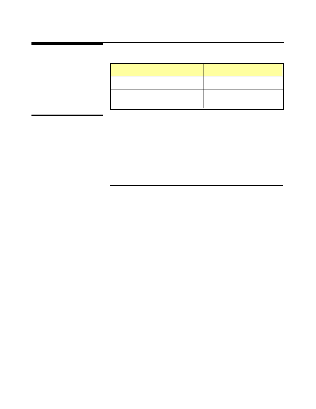
Manual Content
Chap Title Content
1
2
3
4
General
Information
Verification
Tests
Replaceable
Parts
Service Procedures to aid in fault isolation and repair.
Provides a basic description and lists the test equipment required for
service.
Functional verification, operation verific ation, and performance
verification tests.
Replaceable parts lists and illustrations.
6 Agilent E1472A/73A/74A/75A Service Manual

Notes
Agilent E1472A/73A/74A/75A Service Manual 7

Notes
8 Agilent E1472A/73A/74A/75A Service Manual

Table of Contents
Chapter 1 — General In f or mation
Introduction . . . . . . . . . . . . . . . . . . . . . . . . . . . . . . . . . . . . . . . 11
Relay Life . . . . . . . . . . . . . . . . . . . . . . . . . . . . . . . . . . . . . . . . 12
End-of-Life Detection . . . . . . . . . . . . . . . . . . . . . . . . . . . . . . . 13
Replacement Strategy . . . . . . . . . . . . . . . . . . . . . . . . . . . . . . . . 13
Safety Considerations . . . . . . . . . . . . . . . . . . . . . . . . . . . . . . . . . . 14
Warnings and Cautions . . . . . . . . . . . . . . . . . . . . . . . . . . . . . . . 14
Inspection/Shipping . . . . . . . . . . . . . . . . . . . . . . . . . . . . . . . . . . . 16
Initial Inspection . . . . . . . . . . . . . . . . . . . . . . . . . . . . . . . . . . 16
Shipping Guidelines . . . . . . . . . . . . . . . . . . . . . . . . . . . . . . . . 17
Environment . . . . . . . . . . . . . . . . . . . . . . . . . . . . . . . . . . . . . . 18
RF Multiplexer/Expander Description . . . . . . . . . . . . . . . . . . . . . . . . . 18
Agilent E1472A / E1473A Descript io n . . . . . . . . . . . . . . . . . . . . . . . 18
Agilent E1474A / E1475A Descript io n . . . . . . . . . . . . . . . . . . . . . . . 19
Multiplexer/Expander Specifications . . . . . . . . . . . . . . . . . . . . . . . . 19
Multiplexer/Expander Serial Numbers . . . . . . . . . . . . . . . . . . . . . . . 19
Multiplexer/Expander Options . . . . . . . . . . . . . . . . . . . . . . . . . . . 20
Test Kit . . . . . . . . . . . . . . . . . . . . . . . . . . . . . . . . . . . . . . . 20
CLIP . . . . . . . . . . . . . . . . . . . . . . . . . . . . . . . . . . . . . . . . . 20
Recommended Test Equipment . . . . . . . . . . . . . . . . . . . . . . . . . . . . 21
Chapter 2 — Verification Tes t s
Introduction . . . . . . . . . . . . . . . . . . . . . . . . . . . . . . . . . . . . . . . 23
Test Conditions/Procedures . . . . . . . . . . . . . . . . . . . . . . . . . . . . . 23
Performance Test Record . . . . . . . . . . . . . . . . . . . . . . . . . . . . . . 23
Verification Test Examples . . . . . . . . . . . . . . . . . . . . . . . . . . . . . 23
Multiplexer Functional Verification . . . . . . . . . . . . . . . . . . . . . . . . . . 24
Procedure . . . . . . . . . . . . . . . . . . . . . . . . . . . . . . . . . . . . . . 24
Example . . . . . . . . . . . . . . . . . . . . . . . . . . . . . . . . . . . . . . . 24
Expander Functional Verification . . . . . . . . . . . . . . . . . . . . . . . . . . . 24
Procedure . . . . . . . . . . . . . . . . . . . . . . . . . . . . . . . . . . . . . . 24
Example . . . . . . . . . . . . . . . . . . . . . . . . . . . . . . . . . . . . . . . 25
Operation Verification . . . . . . . . . . . . . . . . . . . . . . . . . . . . . . . . . 25
Performance Verification . . . . . . . . . . . . . . . . . . . . . . . . . . . . . . . . 25
Making Test Connections . . . . . . . . . . . . . . . . . . . . . . . . . . . . . . 25
Test 2-1: VSWR Test . . . . . . . . . . . . . . . . . . . . . . . . . . . . . . . . 27
Agilent E1472A/73A/74A/75A Service Manual 9

Performance Test Record . . . . . . . . . . . . . . . . . . . . . . . . . . . . . . . . 33
Test Limits . . . . . . . . . . . . . . . . . . . . . . . . . . . . . . . . . . . . . 33
Measurement Uncertainty . . . . . . . . . . . . . . . . . . . . . . . . . . . . . . 34
Test Accuracy Ratio (TAR) . . . . . . . . . . . . . . . . . . . . . . . . . . . . . 36
Chapter 3 — Replaceable Parts
Introduction . . . . . . . . . . . . . . . . . . . . . . . . . . . . . . . . . . . . . . . 41
Replaceable Parts List . . . . . . . . . . . . . . . . . . . . . . . . . . . . . . . . 41
Exchange Assemblies . . . . . . . . . . . . . . . . . . . . . . . . . . . . . . . . 41
Ordering Information . . . . . . . . . . . . . . . . . . . . . . . . . . . . . . . . 41
Chapter 4 — S e rvic e
Introduction . . . . . . . . . . . . . . . . . . . . . . . . . . . . . . . . . . . . . . . 49
Repair Strategy . . . . . . . . . . . . . . . . . . . . . . . . . . . . . . . . . . . . . 49
Equipment Required . . . . . . . . . . . . . . . . . . . . . . . . . . . . . . . . . 49
Service Aids . . . . . . . . . . . . . . . . . . . . . . . . . . . . . . . . . . . . . 50
Troubleshoot in g . . . . . . . . . . . . . . . . . . . . . . . . . . . . . . . . . . . . . 50
Identifying the Problem . . . . . . . . . . . . . . . . . . . . . . . . . . . . . . . 50
Testing the Assembly . . . . . . . . . . . . . . . . . . . . . . . . . . . . . . . . 51
Isolating to an Assembly . . . . . . . . . . . . . . . . . . . . . . . . . . . . . . . 52
Self-test Error Codes . . . . . . . . . . . . . . . . . . . . . . . . . . . . . . . . . 53
Disassembly . . . . . . . . . . . . . . . . . . . . . . . . . . . . . . . . . . . . . 54
Repair/Maintenance Guidelines . . . . . . . . . . . . . . . . . . . . . . . . . . . . . 57
ESD Precautions . . . . . . . . . . . . . . . . . . . . . . . . . . . . . . . . . . 57
Soldering Printed Circuit Boards . . . . . . . . . . . . . . . . . . . . . . . . . . 57
Post-Repair Safety Checks . . . . . . . . . . . . . . . . . . . . . . . . . . . . . . 57
Appendix A — Verification Tests - C Programs
Functional Verification Tests . . . . . . . . . . . . . . . . . . . . . . . . . . . . . . 59
Example: Multiplexer Self Test . . . . . . . . . . . . . . . . . . . . . . . . . . . 59
Example: Expander Self Test . . . . . . . . . . . . . . . . . . . . . . . . . . . . 60
Performance Verification Test . . . . . . . . . . . . . . . . . . . . . . . . . . . . . . 61
Example: VSWR Test . . . . . . . . . . . . . . . . . . . . . . . . . . . . . . . . 61
10 Agilent E1472A/73A/74A/75A Service Manual

Chapter 1
General Information
Introduction This manual contains information requ ir e d to test, troub le shoot, and rep ai r
the Agilent E1472 A 50 Ohm R F Mul ti pl ex er, the Agilent 1473A 50 Ohm
RF Multiplexe r Expa nde r , the Agilent E1474A 75 Ohm RF Mul tiplexer,
and the Agilent E1475A 75 Ohm RF Multipl ex er Exp an de r (see Fig ur es 1-1
and 1-2).
Figure 1-1. Agilent E1472A/E1474A RF Multiplexers
Agilent E1472A/73A/74A/75A Service Manual General Information 11

Figure 1-2. Agilent E1473A/E1475A RF Multiplexer Expanders
Relay Life Electromechanical relays are subject to normal wear-out. Relay life depends
on several factors . Th e ef fects of loading and switching frequenc y a r e
briefly discuss ed bel ow:
Relay Load. In general, highe r powe r switching reduces relay life. In
addition, capa c it ive /inductive loads a nd high inrush curr en ts (e .g ., whe n
turning on a lam p or motor) reduce relay l if e . Exceeding the specified
maximum inputs can cause c atastrophic failure.
Switching Frequency. Relay contacts heat up when switched. As the
switching frequency increases, the contacts have less time to dissipate heat.
The resulting increase in contact temperature reduces relay life.
12 General Information Agilent E1472A/73A/74A/75A Service Manual

End-of-Life
Detection
A preventive maintenance routine can prevent problems caused by
unexpected rela y f ai lu re. The en d of the li fe of a rela y c an be determined
using one or more of the thr e e methods described below. The best met hod
(or combination of methods), as well as the failure criteria, depends on the
applicatio n in which the relay is used.
Contact Resistance. As the relay begins to wear out , i ts contact resistan ce
will increase. When the resistance exceeds a pre-determined value, the relay
should be replaced. Typically, a relay should be replaced when the contact
resistance exce eds 1.0 Ohm.
Stability of C ontact Resistance. The stability of the contact resistance
decreases with age. Using this method, the contact resistance is
measured several (5-10) times, and the variance of the measurements is
determined. An increase in the variance indicates deteriorating
performance.
Number of Operations. Alternatively, relays can be replaced after a
predetermined number of contact closures. How ever, this method
requires knowledge of the applied load and life specifications for the
applied load. For the Agilent E1472A/73A/74A/75A, maximum relay
life is specified at 5 X 10
at the maximum rated load.
6
operations with no load and 105 operations
Replacement
Strategy
CAUTION
NOTE
The replacement strategy also depends on the application. If all of the relays
see similar loads and switching frequencies, the entire circuit board can be
replaced when the end of life approaches. The sensitivity of the application
should be weighed against the c ost of r eplacing rel ays with some useful life
remaining. In general, individual r elay r epl acement is not recommended for
the Agilent E1472A or Agilent E1474A RF Multiplexers.
The RF relays in these multiplexers are high-mass, high-pin-count
devices. A solder pot is recommended for removal or replacement. If a
solder pot is not available, a RF surface mount soldering iron should be
used. Use of standard soldering equipment will damage the relay and
PC board. Damage to the PC board or relays cause d by improper
soldering techniques is not covered by the product’s warranty.
Relays that wear out normally or fai l due to misuse should not be
considered defective and are not covered by the product’s warranty.
Agilent E1472A/73A/74A/75A Service Manual General Information 13

Safety
Considerations
This product is a Safet y Class I instrument that is provide d wit h a protective
earth terminal when instal le d in the main f r a me. The in strum e n t, ma in f r ame,
and all relate d document at ion should be rev ie w e d fo r fa miliarizat ion with
safety markings and instruc tions before ope r a tion or service.
Refer to the WARNINGS page (page 2) in this manual for a summary of
safety inform at ion. Safety infor mation for t esting and service fo llows and is
also found throughout this manual.
Warnings and
Cautions
WARNING
This section co nta i ns W A RNINGS which must be followed for your
protection and C AUTIONS whi ch must be follo w ed to avoid damage to the
equipment when performing instrument maintenance or repair.
SERVICE-TRAINED PERSONNEL ONLY. The information in this
manual is for service-trained personnel who are familiar
with electronic circuitry and are aware of the hazards involved.
To avoid personal injury or damage to the instrument, do not
perform procedures in this manual or do any servicing unless
you are qualified to do so.
CHECK MAINFRAME POWER SETTINGS. Before applying
power, verif y th at the mainf rame setting ma tch e s the line
voltage and that the correct fuse is installed. An uninterruptible
safety earth ground must be provided from the main power
source to t he suppl ie d po we r co rd set.
GROUNDING REQUIREMENTS. Interruption of the protective
(grounding) conductor (inside or outside the mainframe) or
disconnecting the protective earth terminal will cause a
potential shock hazard that could result in personal injury.
(Grounding one conductor of a two-conductor outlet is not
sufficient protection.)
IMPAIRED PROTECTION. Whenever it is likely that instrument
protection has been impaired, the mainframe must be made
inoperative and be secured against any unintended operation.
REMOVE POWER IF POSSIBLE. Some procedures in this
manual may be performed with power supplied to the
mainfr a me while pr ot e ct iv e covers ar e r em o ve d . Ener gy
available at many points may, if contacted, result in personal
injury. (If maintenance can be performed without power applied,
the power should be removed.)
14 General Information Agilent E1472A/73A/74A/75A Service Manual

WARNING
USING AUTOTRANSFORMERS. If the mainframe is to be
energized via an aut otransf or mer (for voltage reduction) ma ke
sure the common terminal is connected to neutral (that is, the
grounded side of the main’s supply).
CAPACITOR VOLTAGES. Capacitors inside the mainframe may
remain charged even when the mainframe has been
disconnected from its source of supply.
USE PROPER FUSES. For continued protection against fire
hazard, replace t he line fuses only with fuses of th e same
current rating and type (such as normal blow, time delay, etc.).
Do not use repaired fuses or short-circuited fuseholders.
SHOCK HAZARD. Only service-trained personnel who are
aware o f th e ha z ar d s involve d should in stall, rem o ve , o r
confi gu re the mu l ti p lexer or ex p a nd e r . B ef ore you rem ove any
installed module, disconnect AC power from the mainframe and
from other modules that may be connected to the multiplexer or
expander.
CHANNEL WIRING INSULATION. All channels that have a
common connection must be insulated so that the user is
protected from electrical shock. This means wiring for all
channels must be insulated as though each channel carries the
voltage of the highest voltage chann el.
CAUTION
MAXIMUM INPUTS. The maxi m um voltage that can be applied to
any terminal is 42 V Pe ak (an y cen ter or chassis to any other center of
chassis). The maximum current per channel or common is 1 A DC or
AC RMS. The maximum power that can be applied to any channel or
common is 24 W or 24 VA.
STATIC ELECTRICITY. Static electricity is a major cause of
component failure. To prevent damage to the electrical components in
the multiplexer or expander, observe anti-static techniques whenever
working on the device.
RELAY REMOVAL. The RF relays used in these multiplexers are
high-mass, high-pin-count devices. Individual relay removal is not
recommended. A solder pot is required for removal or replacement. Use of
standard soldering equipment will cause damage to the relay and PC board.
Agilent E1472A/73A/74A/75A Service Manual General Information 15
Inspection/
Shipping
This section contains initial (inco mi ng) inspection an d shipping guidelines
for the multiple xe r /e xpander module s.
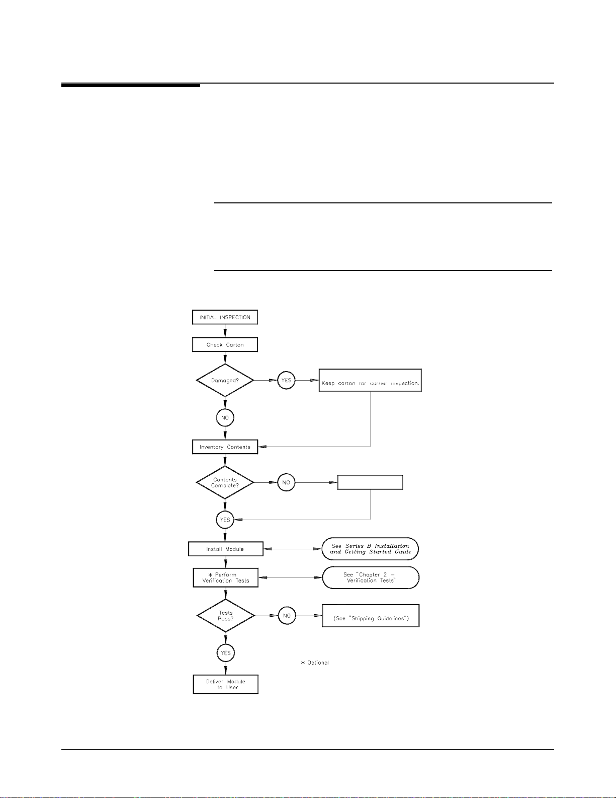
Inspection
WARNING
Initial
Use the steps in Fi gure 1- 3 as guidelines to pe r fo rm initial inspe c tion of one
of the modules. Ve ri fic a ti on Te sts are optional .
To avoid possible hazardous electrical shock, do not perform
electrical tests if there are signs of shipping damage to the
shipping container or to the instrument.
Notify Agilent and carrier.
Notify Agilent
Return to Agilent
Figure 1-3. Initial (Incoming) Inspection Guidelines
16 General Information Agilent E1472A/73A/74A/75A Service Manual

Shipping
Guidelines
Follow the step s in Figure 1-4 to re tur n one of the mult iplexer/expander
modules to a Agile nt Technologi es Sale s a nd Su ppor t Office or Serv ic e
Center.
1 Prepare the Multiplexer
• Remove user wiring from terminal block
• Attach tag to module/pod that identifies
- Owner
- Model Number/Serial Number
- Service Required
• Place tagged device in approved anti-static bag
2 Package the Multiplexer
• Place packaged multiplexer in shipping carton*
• Place 75 to 100 mm (3 to 4 inches) of shock-
absorbing material around the multiplexer.
• Seal the shipping carton securely.
• Mark the shipping carton FRAGILE.
3 Ship the Multiplexer to Agilent Technologies
• Place address label on shipping carton
• Send carton to Agilent Technologies
Figure 1-4. Packaging/Shipping Guidelines
* We reco m m end that you use t he same shippi ng materials as those use d i n factory packaging (avail a b l e from A g i l ent Technologi es ).
For other (com m ercially-available ) sh ipping mate rial s, use a double wall-carton with mini m u m 2. 4 MPa (350 psi) test .
Agilent E1472A/73A/74A/75A Service Manual General Information 17
Environment The recommended operating environment for the multiplexers/ expanders is:
Environment Temperature Humidity
o
Operating 0
C to +55oC <95% relative (0oC to +40oC)
RF Multiplexer/
Expander
Description
NOTE
Agilent
E1472A/E1473A
Description
Storage and
Shipment
The Agilent E1472A a nd E1474A RF Multipl ex er modules are
"instruments" in the slots of a VXIbus mainframe. Each module is assigned
an error queue, input an d output buffers, an d a sta tus register.
Instruments a re base d on the logical ad dre sse s of the plug-in modules. See
the Agilent 75000 Series C Instal lation and Getti ng Started Guide to set the
addresses to create an instrument .
The Agilent E1472A 50 Ohm RF Multiplexe r an d the Agi le nt E1473A 50
Ohm RF Multiplexer Expander are VXI bus C-Size register-based products.
The Agilent E1472A RF Multiplexer and the Agilent E147 3A RF
Multiplexer Expa nder each provide six banks of 4:1 swit c hing. Inputs and
outputs for eithe r module use 50 Ohm SMB con ne cto rs.
o
-40
C to +75oC <95% relative (0oC to +40oC)
The multiplexer and each multiplexer expander consists of six banks of
channels (bank 0 through bank 5) to fo rm six 4:1 multiplexers. Each
channel in a bank is connected to COM when the channel is CLOSed.
Following power-on, power off, or a card reset, the first channel in each
bank is connect e d to C O M.
Channel numberi ng i s in the form bc, where b is the bank numbe r (from 0 to
5) and c is the channel number (from 0 to 3). For example, following a card
reset, channel 20 is closed (that is, channel 0 in bank 2 is connected to COM
20).
The Agilent E1472A RF Multiplex er can con trol up to two addit ional
expander module s f or up to e ighteen banks o f 4:1 swi tc hing. The expander
modules can be eithe r the Agilent E1473A 50 Ohm RF Multiplex er
Expander modul e or the Agilent E1475A 75 Ohm RF Multiplexe r Ex pa nde r
module.
18 General Information Agilent E1472A/73A/74A/75A Service Manual

The Agilent E1473A RF Multiplexer Expander Module ca n be inser ted in a
C-Size VXI bus mainframe next to the multiplexer, or can be located up to
eight meters away from the multiplexer using remote expander cables.
Locating the expander module close to the external device keeps connecting
cable lengths to a minimum, thereby reduci ng the possibility of cross-ta l k
and insertion loss of high frequency signals.
Agilent
E1474A/E1475A
Description
Multiplexer/
Expander
Specifica tio n s
Multiplexer/
Expander
Serial Numbers
The Agilent E1474A 75 Ohm RF Multiplexe r an d the Agi le nt E1475A 75
Ohm RF Multiplexer Expander are identical in operation to the Agilent
E1472A/E1473 A des cri be d ear li e r in this chapter wit h the exc ep tion of the
characteristic impedance of the RF channels.
Inputs and outputs for either modu le use spe c ia l 75 Oh m SM B conne c to rs .
The special connectors and their mating connectors are listed in the Agilent
E1474A/E1475A RF M ul ti plexer/Expander User’s Manual .
Specification s are listed in Appendi x A of the Agilent E1472A/E1473A RF
Multiple x er/RF Multipl e xer Expander User’s Manual and the Agilent
E1474A/E1475A RF Mul ti pl exer/RF Multiplexer Expander User’s Manual.
These specifications are the performance standards or limits against which
the modules may be te ste d.
Devices covered by this manual are identified by a serial number prefix
listed on the title page. Agilent Technologies uses a two-part serial number
in the form XXXXAYYYYY, where XXXX is the serial prefix, A is the
country of origin (A=USA), and YYYYY is the serial suffix. The serial
number prefix identifies a series of identical instruments. The serial number
suffix is assig ne d se que ntially to each instrument . The serial number pla te
is located on the right-hand sh ie l d ne ar the backplane connectors.
Agilent E1472A/73A/74A/75A Service Manual General Information 19

Multiplexer/
Expander
Options
The following cables are availabl e from Agilent Technol ogi e s fo r use wi th
the multipl e xe r/ e xpa nde r. For other cable lengt hs a nd c onfigurations,
contact your Agilent Technol ogi e s sa le s of f ice .
Agilent PN Cable
E1473-80002 Remote Exp ande r Cabl e Ki t to rem ot e mo unt eith er the Agi lent
E1473A or Agilen t E14 75A next to the DUT. Cables ar e 0. 8 Me te rs
long and can be dai sy ch ai ned up to 8 Meters
E1472-61601
8120-5629 Right-angle to righ t-angle female SMB conn ect or (125 mm)
8120-5091 Straight to strai ght fe ma le SMB connector (125 mm)
8120-5609 Right-angle fem ale t o bul khead mount male SMB co nnector (175 mm)
8120-5614 Right-angle fem ale S M B to BNC f em ale connector (175 mm)
8120-5591 Right-angle to righ t-angle female SMB conn ect or (125 mm)
8120-5584 Straight to strai ght fe ma le SMB connector (125 mm)
8120-5580 Right-angle fem ale t o bul khead mount male SMB co nnector (175 mm)
8120-5619 Right-angle fem ale S M B to BNC connector (175 mm)
RMD Cable (3-to-1 C abl e) . Two cables ar e re qui red to oper at e one or
more expander mo dul es.
50 Ω Cables
75 Ω Cables
Test Kit A test kit is availa ble from Agilen t Te c hnol ogies for use in the Per for ma nc e
Verification tests of the Agilent E1474A/E1475A 75 Ω RF
Multiplexer/Expander. Order Agil e nt pa r t nu mbe r E1474-80000. See Tabl e
1-1 for kit parts.
CLIP A CLIP (Component Level Information Packet) is available for the Agilent
E1472A/E1473 A/E1474A/E1475A RF Mul ti ple xe r s/ Expa nders (order
Agilent part nu mbe r E1472-90033). Th is C LI P contains component
loca tors, schematic diagra ms, and detailed part s lists.
20 General Information Agilent E1472A/73A/74A/75A Service Manual

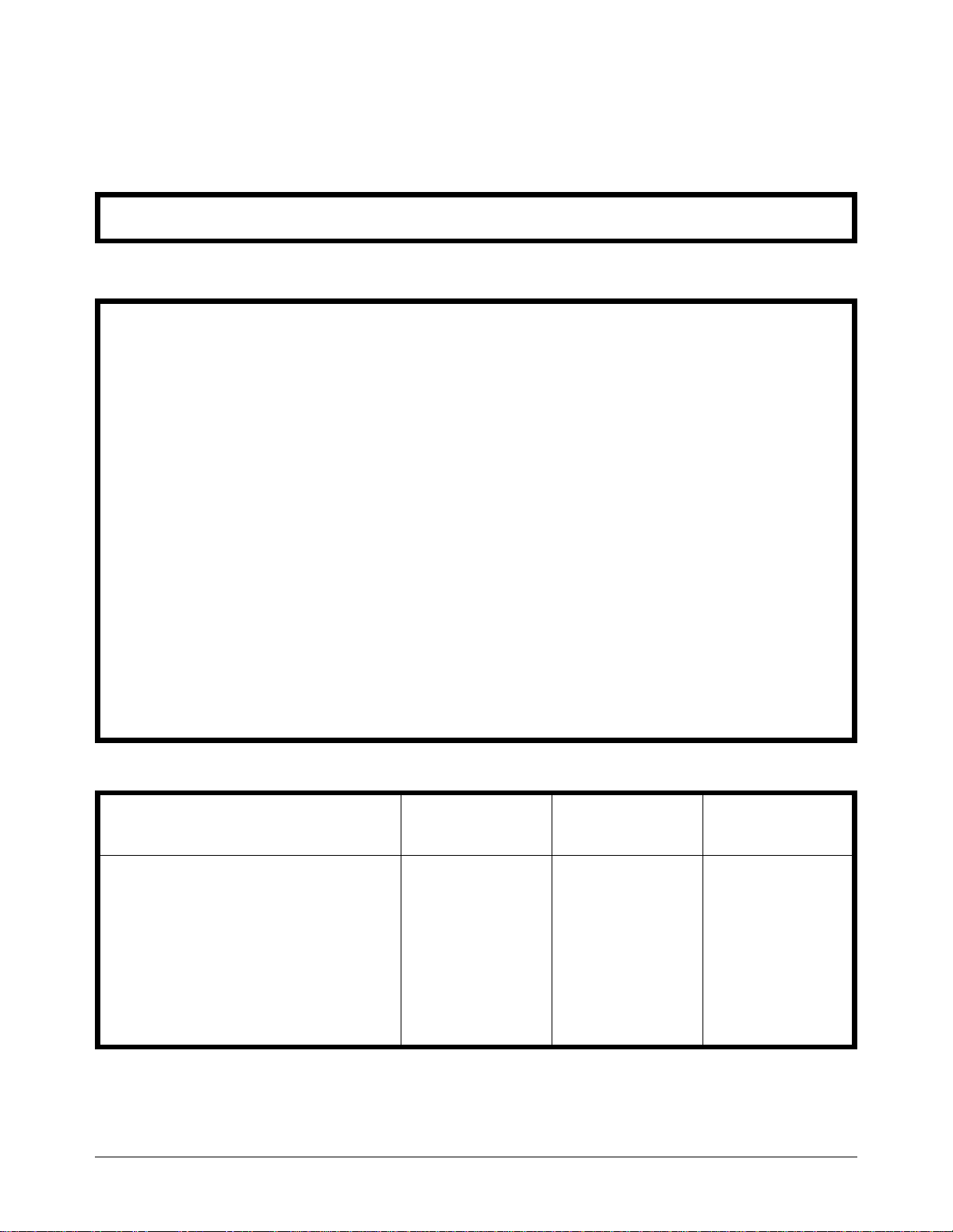
Recommended
Test Equipment
Table 1-1 list s the te st equipment recommended f or testing and servi cing the
module. Essential requirements for each piece of test equipment are
described in the Requirements column. Other equipment may be substituted
as long as it meets the requirements shown in the Requirements column.
Table 1-1. Recommended Test Equipment
Instrument Requirements Recommended
Model
Controller, GPIB GPIB compatibility as defined by IEEE Standard
488-1988 and the identical ANSI Standard
MC1.1: SH1, AH1, T2, TE0, L2, LE0, SR0,
RL0, PP0, DC0, DT0, and C1 , 2, 3,
4, 5.
Mainf rame Compatible with multiplexer/expander E1401B/T or E142 1B
Command Module Compatible with mu ltiplexer/expander E1405A/B or
HP 9000 Series 300
or
IBM Compatible PC with
BASIC
(requires E 1405A/B or
E1406A)
E1406A
Network Analyzer VSWR from 10 MHZ to 3 GHz. Agilent 8753C
S-Parameter Test Set Compatible with Agilent 8753C , single port
50 Ω for Agilent E1472A/E1473A
75 Ω for Agilent E1474A/E1475A
Adapters and Cables
E1472A/E1473A 50 Ω
APC-7-to-SMA (female)
SMA-to-SMA cable (male-male)
SMA -to- SMB (female-female)
SMB LOAD(female)
SMB SHORT (male)
SMB Feedthrough (male-male)
Agilent 85046A for Agilent
E1472A/E1473A
or
Agilent 85046B for Agilent
E1474A/1475A
50 Ω impedance
Agilent PN 11534A
—————
—————
Agilent PN 1250-0676
—————
—————
Use*
F,O,
P,T
F,O,
P,T
F,O,
P,T
O, P,T
O, P,T
O, P,T
E1474A/E1475A 75 Ω
Test Kit (contains the following parts)**
N-to-SMB cable (male-female)
SMB OPEN (male)
SMB LOAD (female)
SMB SHORT (male)
SMB Feedthrough (male-male)
Digital Multimeter 4-wire ohms
2-wire ohms (up to 1 GΩ )
75 Ω impedance
Agilent PN E1474-80000**
Agilent PN 8120-4482
Agilent PN 1250-2354
Agilent PN 1250-2343
Agilent PN 1250-2358
Agilent PN 1250-2337
Agilent 3458A or
Agilent 34401A
T
* F = Functional Verificati on Tests, O = Oper at i on V er i fi cation Test s, P = Per for m ance Verific ation Tests, T = T r oubl eshooting
** Test Kit must be ordere d as a separate par t f rom A gi lent Tech nol ogi es
Agilent E1472A/73A/74A/75A Service Manual General Information 21

22 General Information Agilent E1472A/73A/74A/75A Service Manual

Chapter 2
Verification Tests
Introduction The three levels of te st procedures des cri be d in this chapte r are us ed to
verify that the multiplexer or multiplexer expander:
• is fully function al (Functional Verification)
• meets selected testable specifications (Operation Verification)
• meets all testable specifications (Performance Verification)
Test Conditions/
Procedures
Performance
Test Record
Verification Test
Examples
See Table 1-1 for test e quipment requir e ments. You should complete the
Performance Verificati on tests at least once a year. Fo r heavy use or severe
operating e nviro nments , perfo r m the tests more often.
The verification tests assume that the person performing the tests
understands how t o ope r at e the ma inframe, the mu ltiplexer/e xpa nde r , and
specified test e quipment. The test pr oc e dure s do not specify equi pment
settings for test equipment, except in general terms. It is assumed that a
qualified, service-trained technician will select and connect the cables,
adapters, and probes required for the test.
o
It is assumed that the temperature is no greater than 25
humidity is no gre a ter than 40% .
The results of each Performance Verification test may be recorded in the
Performance Test Re c ord (T ab le 2- 3) .
Each verification test procedure includes an example program that performs
the test. All example programs assume the following:
C and the rela tive
• Controller is an HP 900 0 Serie s 200 /300 computer
• Programming la nguage is BASIC
• Switch address is 70915
• Switch card number is 1
Agilent E1472A/73A/74A/75A Service Manual Verification Tests 23

Multiplexer
Functional
Verification
Procedure 1. Verify that the multiplexer is installed in the mainframe and that the
Example An example follows which uses an HP 9000 Ser ies 300 computer with
The Functional Verif ica ti on Te st for the Agilent E1472A/E1474A
multiplex ers consists of sendi ng the *TST? comm a nd a nd c he ck ing the
response. This test can be used to verify that the device is connected
properly and is resp onding to basic commands.
mainframe has passed its power-on test.
2. Send the *TST? command to the device (see example following).
3. The device will return an error code. Any non-zero error code indic ates
a self-test failure. See Table 4- 3 f or a descript ion of se lf -test error c odes.
BASIC and an multi ple xe r ad dres s of 70915.
10 OUTPUT 70915;"*TST?" Send the self-test command
20 ENTER 70915;A Get response
30 PRINT A
40 END
Expander
Functional
Verification
Procedure 1. Verify that the multiplexer is installed in the mainframe and that both
The Functional Verific ation Test for the Agilent E1473A/E1475A RF
Multiplexer Expanders consist s of se nding the :COPTio n? que ry comma nd
and checking t he respo n se . This test can be use d to ve r ify that the devi ce i s
connected properly and is responding to basic commands.
the mainframe and multiplexer have passed the power-on test. This
test assumes the conditions l ist e d in Test Conditions/Procedures in
this chapter.
2. Sen d the SYSTem :COPT i on? query command to the device (see
example following) .
3. The multiplexer wi ll retur n a string in dicating if a ny expan de r
modules are connected. The string is in the form:
E1474A,E1475A,0 if only a single expander module (in this ca se
an Agilen t E 14 75A) is connected to th e multiplexer .
The first parameter of the returned string indicates the type of multiplexer
installed in the mainframe (Agilent E1472A or E1474A). The second
parameter in the string is the model number of the first installed expander
module, and the last parameter in the string is the model number of a
second ins tal l ed ex pan der mo du le. I f n o ex pan der modules are installed,
the string returned will be E1474A,0,0 and indicates a failure.
24 Verification Tests Agilent E1472A/73A/74A/75A Service Manual

Example An example follows which uses an HP 9000 Ser ies 300 computer with
BASIC and an multiplexer addr ess of 70915. The multiplexer is assum e d to
be switch card 1.
10 DIM A$[50]
20 OUTPUT 70915;"SYST:COPT? 1" Send identify opt ion s command
30 ENTER 70915;A$ Get response
40 PRINT A$
50 END
Operation
Verification
Performance
Verification
The procedures in th is se c ti on a r e us ed to provide a high degree of
confidence tha t the multiplexer/ ex pa nde r is mee ti ng published
specifications. The Operation Verification tests are usually a subset of the
Performance Verifica ti on tests and are suitable for checkout after
performing repairs.
For the Agilent E147 2A/E1474A RF Mult ipl e xe r modules, Operation
Verification is per f or med by c ompleting the VSW R Tes t as de sc ribe d in the
performance verif ica tion test procedur e s (T es t 2-1) . T his test is usually
sufficient to verify that the instrument is meeting its specifications.
The procedures in this section a r e us ed to te st the mult iplexer’s electr i ca l
performance using t he speci fic a ti ons i n Appe ndix A of the Agilent E1472A
/E1473A User’s Manual or Agilent E1474A /E1475A User’s Manual as t h e
performance stan da rd s.
The performance verification test is a test of the VSWR for each channel of
the multiplexer. This test is sufficient to determine that the multiplexer is
operating within specifications. This test is suitable for incoming inspection,
troublesho oting, and preve n ti ve ma intenance .
Making Test
Connections
Figure 2-1 shows typi cal te st c onnections, cabl es , and a da pt ers re quired to
test the Agile nt E1472A/E1473A 50 Ohm RF Multiplexer/Expander.
Figure 2-2 shows typi cal te st c onnections, cabl es , and a da pt ers re quired to
test the Agile nt E1474A/E1475A 75 Ohm RF Multiplexer/Expander.
Figure 2-3 shows the RMD cable connections needed to test either the
Agilent E1473A or Agilent E1475A RF Mu lt iplexer Expander . Refe r to the
list of mult iplexer/expande r options in Chapte r 1 fo r RMD cable part
numbers.
Agilent E1472A/73A/74A/75A Service Manual Verification Tests 25

Figure 2-1. 50 Ohm Test Cables and Adapters
Figure 2-2. 75 Ohm Test Cables and Adap t ers
26 Verification Tests Agilent E1472A/73A/74A/75A Service Manual
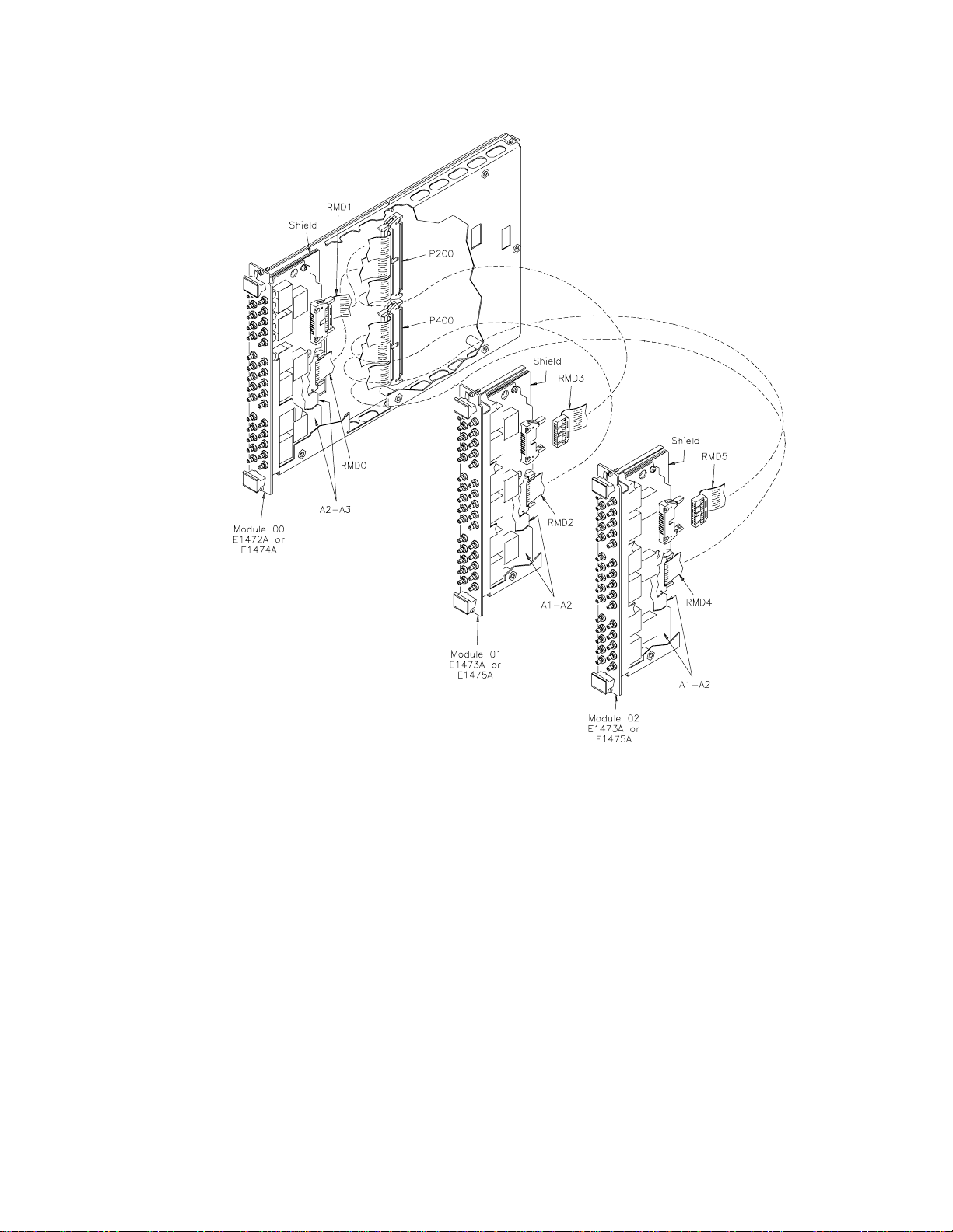
Figure 2-3. RF Multiplexer Expander Connections
Test 2-1: VSWR
Test
This test checks to see if all channels meet the VSWR specification for the
multiplexer.
100 MHz to 500 MHz
Measurements 1. Setup and Calibrate the Network Analyzer
• Turn on the test set an d allow at least a one-h our warm up period.
• Press the PRESET button.
• Select the SWR measurement type from the FORMAT menu.
• Set the START frequency to 100 MHz and the STOP frequency to
500 MHz.
• Select the CAL menu. Select the 3.5 mm cal kit.
Agilent E1472A/73A/74A/75A Service Manual Verification Tests 27

• From the CAL menu, select a single port measurement (typically
port S11).
• Calibrate the port for OPEN, SHORT, and LOAD using the
appropriate test connectors on the cable that will be used for the
test (refer to Table 1-1). Press DONE when the Network Analyzer
indicates it is calibrated and ready for a measurement.
• Set an appropriate scale per division to measure the VSWR
(typically 100 mV/DIV).
NOTE
The connectors, cables, adapters, loads, and shorts used to calibrate the
Network Analyzer must be the same connectors, cables, adapters, and loads
used in the VSWR tests.
2. Measure Bank 0 VSWR
• Turn mainframe power ON
• Send *RST to multip le xe r
• Connect th e Por t 1 te st cable to the COM 00 por t on the
multiple xe r /e xpa nder as shown in Figure 2- 4.
• Install the appropriate load on Channel 00 as shown in Figure 2-4.
• Send CLOS (@ccmm00) to close chan 00, where cc = card
number and mm = module numbe r .
• Observe the Network Analyzer response. Select ma rker se arch for
MAX (or, manually locate the maximum value indicated) and
record the measurement VSWR in Table 2-3 for Channel 00.
• Send OPEN (@ccmm00) to open chan 00, where cc = card
number and mm = module numbe r .
28 Verification Tests Agilent E1472A/73A/74A/75A Service Manual
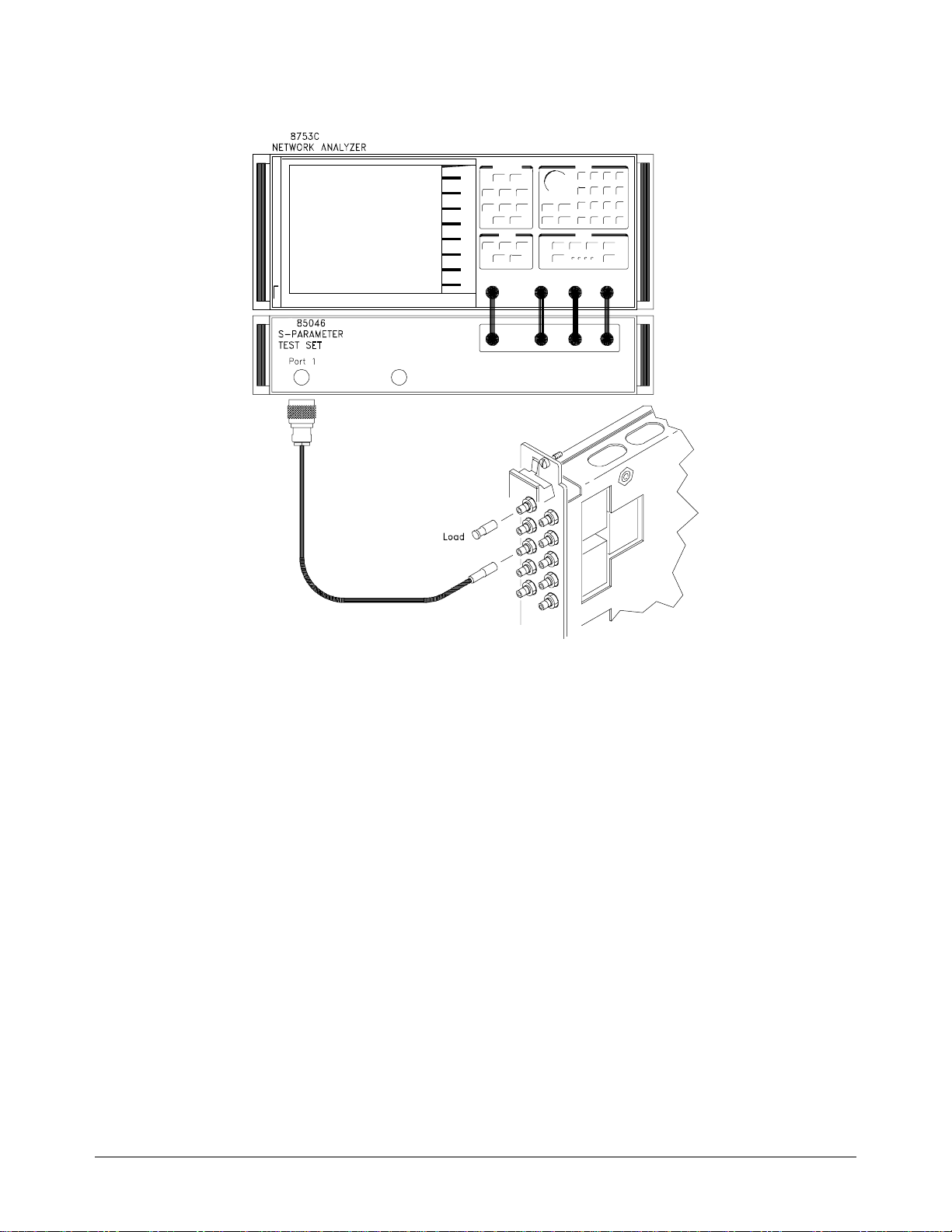
Figure 2-4. Channel 00 VSWR Test Con nections
3. Repeat for Channels 01, 02, an d 03
• Repeat step 2 for channe ls 01, 02 and 03.
• Move the load to the channel under test.
• Use CLOS (@ccmmnn) and OPEN (@ccmmnn), where cc = card
number, mm = mod ule number, and nn = channe l number.
4. Repeat for Banks 1, 2, 3, 4, an d 5
• Repeat steps 2 and 3 f or the rem ai ni ng ba nks and channels.
• Connect the P or t 1 test cable to th e CO M por t on the Bank being
tested.
• Install the appropriate load on each channel as shown in Figure
2-4.
500 MHz to 1.3 GHz
Repeat Test 2-1, 100 M Hz to 500 MHz Test with th e fol lowi ng c ha nge s:
Measurements
• In Step 1, set the START frequency to 500 MHz and the stop
frequency to 1.3 GHz.
Agilent E1472A/73A/74A/75A Service Manual Verification Tests 29

Example This example performs the VSWR Test fo r the Agil en t E1472A/E1474A
and Agilent E1473A/E1475A. If a channel fai ls t he VSWR t est, a mes sage
indicating the failing chan nel number is printed and the progra m pa us es .
10 ! RE-SAVE "VSWR_72"
20 DIM Result1(3,5),Result2(3,5)
30 Cc$="01" ! Card Number
40 Mm$ = "00" ! Module Number
50 ASSIGN @Mux TO 70915
60 DISP CHR$(129)
70 CLEAR SCREEN
80 PRINT "Select the test to run"
90 PRINT "Test 1. RF Multiplexer (Agilent E1472A or E1474A)"
100 PRINT "Test 2. RF Multiplexer Expander (Agilent E1473A or E1475A)"
110 INPUT "Enter the test number (1 or 2)",Tst
120 IF Tst = 2 THEN
130 Mm$ = "01"
140 END IF
150 CLEAR SCREEN
160 PRINT "Equipment Setup"
170 PRINT
180 PRINT " 1. Turn Network Analyzer ON, allow a 1 hour warm-up"
190 PRINT " 2. Install Agilent E1472A or E1474A RF Multiplexer in
mainframe"
200 IF Tst = 2 THEN
210 PRINT " 2a. Install Agilent E1473A or E1475A Expander"
220 END IF
230 PRINT " 3. Turn mainframe power ON"
240 DISP "Press Continue when ready to begin testing"
250 PAUSE
260 CLEAR SCREEN
270 PRINT "Calibrate the Network Analyzer"
280 PRINT
290 PRINT " 1. Press PRESET"
300 PRINT " 2. Select SWR measurement type from the FORMAT menu"
310 PRINT " 3. Set the START frequency to 100 MHz"
320 PRINT " 4. Set the STOP frequency to 500 MHz"
330 PRINT " 5. Select the 3.5 mm CAL kit"
340 PRINT " 6. Calibrate the test port and cable for OPEN, SHORT, and
LOAD"
350 PRINT " 7. Set the scale to 100 mV/DIV"
360 DISP "Press Continue when ready to begin testing"
370 PAUSE
380 CLEAR SCREEN
30 Verification Tests Agilent E1472A/73A/74A/75A Service Manual

390 OUTPUT @Mux;"*RST"
400 FOR K = 0 TO 5
410 PRINT TABXY(1,1),"VSWR from 100 MHz to 500 MHz"
420 FOR I = 0 TO 3
430 CLEAR SCREEN
440 PRINT TABXY(1,3),"1. Connect test port cable to COM ";VAL$(K);"0"
450 PRINT TABXY(1,4),"2. Connect LOAD to Channel ";VAL$(K);VAL$(I)
460 DISP "Press Continue when test connections are complete"
470 PAUSE
480 OUTPUT @Mux;"CLOS (@"&Cc$&Mm$&VAL$(K)&VAL$(I)&")"
490 PRINT
500 PRINT "Observe the Network Analyzer display"
510 PRINT "Note the highest measured VSWR reading"
520 INPUT "Enter measured value",Result1(I,K)
530 IF Result1(I,K)>1.25 THEN
540 PRINT
550 PRINT "Channel "&VAL$(K)&VAL$(I)&" FAILED -- VSWR > 1.25"
560 PRINT "Press Continue to test the next channel"
570 PAUSE
580 CLEAR SCREEN
590 END IF
600 NEXT I
610 NEXT K
620 OUTPUT @Mux;"*RST"
630 CLEAR SCREEN
640 PRINT "100 MHz to 500 MHz VSWR test complete"
650 DISP "Press Continue for 500 MHz to 1.3 GHz VSWR Test"
660 PAUSE
670 CLEAR SCREEN
680 PRINT "Equipment Setup"
690 PRINT
700 PRINT " 1. Turn network Analyzer ON, allow a 1 hour warm-up"
710 PRINT " 2. Install Agilent E1472A or E1474A RF Multiplexer in
mainframe"
720 IF Tst = 2 THEN
730 PRINT " 2a. Install Agilent E1473A or E1475A Expander"
740 END IF
750 PRINT " 3. Turn mainframe power ON"
760 DISP "Press Continue when ready to begin testing"
770 PAUSE
780 CLEAR SCREEN
790 PRINT "Calibrate the Network Analyzer"
Agilent E1472A/73A/74A/75A Service Manual Verification Tests 31

800 PRINT
810 PRINT " 1. Press PRESET"
820 PRINT " 2. Select SWR measurement type from the FORMAT menu"
830 PRINT " 3. Set the START frequency to 500 MHz"
840 PRINT " 4. Set the STOP frequency to 1.3 GHz"
850 PRINT " 5. Select the 3.5 mm CAL kit"
860 PRINT " 6. Calibrate the test port and cable for OPEN, SHORT, and
LOAD"
870 PRINT " 7. Set the scale to 100 mV/DIV"
880 DISP "Press Continue when ready to begin testing"
890 PAUSE
900 CLEAR SCREEN
910 OUTPUT @Mux;"*RST"
920 FOR K = 0 TO 5
930 PRINT TABXY(1,1),"VSWR from 500 MHz to 1.3 GHz"
940 FOR I = 0 TO 3
950 CLEAR SCREEN
960 PRINT TABXY(1,3),"1. Connect test port cable to COM
";VAL$(K);"0"
970 PRINT TABXY(1,4),"2. Connect LOAD to Channel
";VAL$(K);VAL$(I)
980 DISP "Press Continue when test connections are complete"
990 PAUSE
1000 OUTPUT @Mux;"CLOS (@"&Cc$&Mm$&VAL$(K)&V AL$(I )&") "
1010 PRINT
1020 PRINT "Observe the Network Analyzer display"
1030 PRINT "Note the highest measured VSWR reading"
1040 INPUT "Enter measured value",Result1(I,K)
1050 IF Result1(I,K)>1.35 THEN
1060 PRINT
1070 PRINT "Channel "&VAL$(K)&VAL$(I)&" FAILED -- VSWR >1.35"
1080 PRINT "Press Continue to test the next channel"
1090 PAUSE
1100 CLEAR SCREEN
1110 END IF
1120 NEXT I
1130 NEXT K
1140 OUTPUT @Mux;"*RST"
1150 CLEAR SCREEN
1160 PRINT "500 MHz to 1.3 GHz VSWR test complete"
1170 DISP "Press Continue to display measurement results"
1180 PAUSE
1190 CLEAR SCREEN
32 Verification Tests Agilent E1472A/73A/74A/75A Service Manual

1200 !
1210 ! Print Measurement Results
1220 !
1230 PRINT " 100 MHz to 500 MHz "
1240 PRINT
1250 Format: IMAGE 2("Channel ",D,D," VSWR = ",D.DDD,5X)
1260 FOR K = 0 TO 2
1270 FOR I = 0 TO 3
1280 PRINT USING Format;K,I,Result1(I,K),K+3,I ,Result1(I,K+3)
1290 NEXT I
1300 NEXT K
1310 PRINT
1320 PRINT " 500 MHz to 1.3 GHz "
1330 PRINT
1340 FOR K = 0 TO 2
1350 FOR I = 0 TO 3
1360 PRINT USING Format;K,I,Result2(I,K),K+3,I ,Result2(I,K+3)
1370 NEXT I
1380 NEXT K
1390 END
Performance
Test Record
Test Limits Test limits are define d f or VSWR us ing the specificati ons in Appe ndix A of
Table 2-3 is a form you can c opy a nd us e t o recor d pe r forma nc e ver ifi cation
test results for the multip le xe r /e xpa nder. Information concerning test limits,
measurement uncertainty, and test accuracy ratio (TAR) is provided below.
the Agilent E1472A User’s Manual or the Agilent E1474A User’s Manual.
The VSWR specifications are single-sided, (i.e., there is an upper limit but
no lower limit). In the Pe r formance Test Record, th e Minimum column is
blank.
Agilent E1472A/73A/74A/75A Service Manual Verification Tests 33

Measurement
Uncertainty
For the performance verification tests in this manual, measurement
uncertainties a re ca lculated based on an Agilent 8753C Netw ork Ana lyz e r
used with an Agile nt 85046A 50 Ohm S-Para meter Test Set for the Agil e nt
E1472A/E1473 A VSWR Test and an Agilent 85046B 75 Ohm S-Paramete r
Test Set for the Agilent E1474A/E1475A VSWR Test. The measurement
uncertainty shown in Table 2-3 is c omputed using the 50 a nd 75 Ohm 3.5
mm connectors and the 3.5 mm CAL kit. The calculations follow.
VSWR Test
Assumptions:
• no change of temperature during the measurements
• all calculations are for a one-port test, all parameters related to port-2 are
set to 0.00
• calculations use typi c al pa ram ete rs for th e 3.5 mm CAL kit as prov ide d
in the Agile nt 85046C System Perf or manc e Ma nua l a nd shown in Table
2-2
34 Verification Tests Agilent E1472A/73A/74A/75A Service Manual

Table 2-2. Parameters used in Measurement Uncertainty Equations
Symbol Error Term Linear Value
@ 500 MHz
Linear Value
@ 1.3 GHz
D Directivity 0.010 0.010
T
r
M
s
A
M
Reflection Tracking 0.016 0.016
Source Match 0.015 0.015
Dynamic Accurac y (Magnit ude) * 0.035 0.035
S11 S11** 1.250 1.350
N
l
N
h
R
r
R
t
T
rd
S
r1
Connector Reflection Repeatability 0.00032 0.00032
Connector Transmissi on Repeatability 0.00032 0.00032
Magnitude drift due to temperature 0.000 0.000
Noise Floor 0.000 0.000
High Level Noise 0.00046 0.00046
Cable Reflection Stability 0.00032 0.00032
* Worst case Re fe re nce Power Level = 0 dbm
** S11 is a measured value, not an error term. The measurement uncertainty is calculated using the
maximum VSWR specification as the S11 term.
Measurement Uncertainty Equations Used
Yr = random port 1 repeatability = Rr1 + 2 ∗ Rt1 ∗ S11 + Rr1 ∗ S11
Xr = random high−level noise = 3 ∗ Nh ∗ S11
= random low −level noise = 3 ∗ N
W
r
l
Sr = systematic error = D + Sr1 + Tr ∗ S11 + (Ms + Sr1 ) ∗ S112 + Am ∗ S11
2
2
= S
+ √ W
V
r
r
+ X
r
+ Y
r
2
r
Er (linear) = reflection uncertainty magnitude = Vr + S11 ∗ Trd (magnitude)
2
Agilent E1472A/73A/74A/75A Service Manual Verification Tests 35

Measurement Uncertainty @ 500 MHz
Measurement Uncertainty is calculated using the values in Table 2-2 as
follows:
Yr = 0.00032 + 2 ∗ 0.00032∗1.250 + 0.00032 ∗ 1.2502 = 0.0016
= 3 ∗ 0.00046 ∗ 1.250 = 0.0017
X
r
= 3 ∗ 0.000 = 0.000
W
r
S
= 0.010 + 0.00032 + 0.016 ∗ 1.250 + (0.015 + 0.00032) ∗ 1.2502 + 0.035 ∗ 1.250 = 0.0980
r
= 0.0980 + √ 0.0016
V
r
M.U. = E
(linear) = 0.1003 + 1.250 ∗ 0.000 = 0.1003
r
2
+ 0.00172 = 0.1003
Measurement Uncertainty @ 1.3 GH z
Measurement Uncertainty is calculated using the values in Table 2-2 as
follows:
Yr = 0.00032 + 2 ∗ 0.00032∗1.350 + 0.00032 ∗ 1.3502 = 0.0018
X
= 3 ∗ 0.00046 ∗ 1.350 = 0.0019
r
= 3 ∗ 0.000 = 0.000
W
r
S
= 0.010 + 0.00032 + 0.016 ∗ 1.350 + (0.015 + 0.00032) ∗ 1.3502 + 0.035 ∗ 1.350 = 0.1071
r
= 0.1071 + √ 0.0019
V
r
M.U. = E
(linear) = 0.1097 + 1.350 ∗ 0.000 = 0.1097
r
2
+ 0.00182 = 0.1097
Test Accuracy
Ratio (TAR)
Test Accuracy Ratios are not defined for single-sided measurements, so all
VSWR measurements have ’NA’ (Not Applicable) in the TAR column.
36 Verification Tests Agilent E1472A/73A/74A/75A Service Manual
Model _______________________ Report No. ________________________ Date _________
General Informati on
Test Facility:
Table 2-3. Performance Test Recor d (P age 1 of 3)
Name ________ ____ _________________________
Address
_____________________________________
City/State ___________________________________
Phone _____________________________________
Special Note s :
_____________________________________________________________________________________________
_____________________________________________________________________________________________
____________________________________________________________________________________________
____________________________________________________________________________________________
____________________________________________________________________________________________
_____________________________________________________________________________________________
Report No. _________________________________
Date _____________________________________
Customer ___________________________________
Tested by __________________________________
Test Equipment Used
Test Equipment Used:
Description
1. _______________________________
2. _______________________________
3. _______________________________
4. _______________________________
5. _______________________________
Model No. Trace No. Cal Due Date
_______________
_______________
_______________
_______________
_______________
_______________
_______________
______________
_______________
_______________
_______________
_______________
_______________
_______________
_______________
Agilent E1472A/73A/74A/75A Service Manual Verification Tests 37
Table 2-3. Performance Test Recor d (P age 2 of 3)
Model _______________________ Report No. ________________________ Date _____ ____
Test No/Descri ption Minimum*
Value
2-1. VSWR Test
VSWR 100 MHz to
500 MHz
Channel 00
Channel 01
Channel 02
Channel 03
Channel 10
Channel 11
Channel 12
Channel 13
Channel 20
Channel 21
Channel 22
Channel 23
Channel 30
Channel 31
Channel 32
Channel 33
Measured Value Maximum
___________________
___________________
___________________
___________________
___________________
___________________
___________________
___________________
___________________
___________________
___________________
___________________
___________________
___________________
___________________
___________________
Value
1.25
1.25
1.25
1.25
1.25
1.25
1.25
1.25
1.25
1.25
1.25
1.25
1.25
1.25
1.25
1.25
Meas
Uncert
1.003E-1
1.003E-1
1.003E-1
1.003E-1
1.003E-1
1.003E-1
1.003E-1
1.003E-1
1.003E-1
1.003E-1
1.003E-1
1.003E-1
1.003E-1
1.003E-1
1.003E-1
1.003E-1
Test Acc
Ratio (TAR)
NA
NA
NA
NA
NA
NA
NA
NA
NA
NA
NA
NA
NA
NA
NA
NA
Channel 40
Channel 41
Channel 42
Channel 43
Channel 50
Channel 51
Channel 52
Channel 53
___________________
___________________
___________________
___________________
___________________
___________________
___________________
___________________
1.25
1.25
1.25
1.25
1.25
1.25
1.25
1.25
1.003E-1
1.003E-1
1.003E-1
1.003E-1
1.003E-1
1.003E-1
1.003E-1
1.003E-1
NA
NA
NA
NA
NA
NA
NA
NA
*Single-sided specification - Minimum value does not app ly
38 Verification Tests Agilent E1472A/73A/74A/75A Service Manual
Table 2-3. Performance Test Recor d (P age 3 of 3)
Model _______________________ Report No. ________________________ Date _________
Test No/Descri ption Minimum*
Value
2-1. VSWR Test
VSWR 500 MHz to
1.3 GHz
Channel 00
Channel 01
Channel 02
Channel 03
Channel 10
Channel 11
Channel 12
Channel 13
Channel 20
Channel 21
Channel 22
Channel 23
Channel 30
Channel 31
Channel 32
Channel 33
Measured Value Maximum
___________________
___________________
___________________
___________________
___________________
___________________
___________________
___________________
___________________
___________________
___________________
___________________
___________________
___________________
___________________
___________________
Value
1.35
1.35
1.35
1.35
1.35
1.35
1.35
1.35
1.35
1.35
1.35
1.35
1.35
1.35
1.35
1.35
Meas
Uncert
1.097E-1
1.097E-1
1.097E-1
1.097E-1
1.097E-1
1.097E-1
1.097E-1
1.097E-1
1.097E-1
1.097E-1
1.097E-1
1.097E-1
1.097E-1
1.097E-1
1.097E-1
1.097E-1
Test Acc
Ratio (TAR)
NA
NA
NA
NA
NA
NA
NA
NA
NA
NA
NA
NA
NA
NA
NA
NA
Channel 40
Channel 41
Channel 42
Channel 43
Channel 50
Channel 51
Channel 52
Channel 53
___________________
___________________
___________________
___________________
___________________
___________________
___________________
___________________
1.35
1.35
1.35
1.35
1.35
1.35
1.35
1.35
1.097E-1
1.097E-1
1.097E-1
1.097E-1
1.097E-1
1.097E-1
1.097E-1
1.097E-1
NA
NA
NA
NA
NA
NA
NA
NA
*Single-sided specification - Minimum value does not app ly
Agilent E1472A/73A/74A/75A Service Manual Verification Tests 39

40 Verification Tests Agilent E1472A/73A/74A/75A Service Manual

Chapter 3
Replaceable Parts
Introduction This chapter contains information for ordering replaceable parts for the
Agilent E1472A/ 74A R F Mul ti plexers and Agilent E1473A/75A RF
Multiplexer Expa nder modules.
Replaceable
Parts List
Exchange
Assemblies
Ordering
Information
Table 3-2 thro ugh 3-5 list replacea ble parts for the m ultiplexer s an d
expanders. Table 3-6 shows reference design ator s for these pa rts, an d Ta ble
3-7 shows the manufacturer code list for these parts.
Table 3-1 lists assemblies that may be replaced on an exchange basis.
Exchange assemblies are available only on a trade-in basis. Defective
assemblies must be returned for credit. Order assemblies for spare parts
stock by the new as sembly part number .
To order a part listed in this chapter, specify the Agilent Technologies part
number and the qua ntity required . Sen d the or de r to your ne a rest
Agilent Technologies Sales and Support Office.
Agilent E1472A/73A/74A/75A Service Manual Replaceable Parts 41

Table 3-1. Exchange/Replaceable Assemblies
Model Assembly Exchange PN Replaceable PN
Agilent E1472A
Agilent E1473A
Agilent E1474A
Agilent E1475A
RMD Cable
A1
A2-A3
A1-A2 —————— E1472-66502
A1
A2-A3
A1-A2 —————— E1474-66502
3-to-1 Cable E1472-61601
E1472-69501
——————
E1472-69501
——————
E1472-66501
E1472-66502
E1472-66501
E1474-66502
Table 3-2. Agilent E1472A Replaceable Parts
Reference
Designator
A1 E1472-66501 1 PC ASSEMBLY RF COAX MUX 28480 E1472-66501
F500-F503 2110-0712 4 FUSE-S UBMINIA TURE 4A 125V NTD AX 75915 R2510 04T1
A2-A3 E1472-66502 2 RELAY PRINTED CIRCUIT ASSEMBLY 28480 E1472-66502
CBL1 E1472-61601 1 CABLE-INTERCONNECT 28480 E1472-61601
Agil e n t P ar t
Qty Part Description Mfr.
Number
50 OHM RF MULTIPLEXER ASSEMBLY
(See Figure 3-1)
1251-7584 3 CONNECTOR-POST TYPE .100-PIN-SPCG
1252-1371 1 CONNECTOR-POST TYPE .100-PIN-SPCG
8120-2981 1 CABLE-FLAT-RIBBON 28AWG 60-CNDCT
20-CONTACT
60-CONTACT
GRA-JKT
Mfr. Part
Code
18873 66900-220
18873 66900-260
76381 3365-60
Number
HDW1-HDW30 2950-0078 30 NUT-HEX-DBL-CHAM 10-32-THD .067-IN-THK 74163 500220
MNL1 E1472- 90001 1 E1472A/E1473 A USER’S MANUAL 28480 E1472-900 01
MP1 E1300 - 45 10 2 1 HA ND LE K IT- B O TTO M , VXI 28480 E1300- 45 10 2
MP2 E1300 - 45 10 1 1 HA ND LE K IT-TOP, Agil ent 28480 E1300- 45 10 1
MP3 8160-0686 1 RFI STRIP-FINGERS BE-CU TIN-PLATED 30817 00786-185
MP4 1400-0482 1 CABLE TIE .062-3-DIA .14-WD NYLON 59730 TY-26M-8
PNL1 E1472-00201 1 FRONT PANEL 28480 E1472-00201
SCR1-SCR2 0515-0368 2 SCREW-MACHINE M2.5 X 0.45 12MM-LG PAN-HD 28480 0515-0368
SCR3-SCR5 0515-0664 3 SCREW-MACHINE M3 X 0.5 12MM-LG PAN-HD 28480 0515-0664
SCR6-SCR13 0515-1135 8 SCREW-MACHINE M3 X 0.5 25MM-LG FLAT-HD 28480 0515-1135
SCR14-SCR17 0515-1375 4 SCREW-MACHINE M2.5 X 0.45 6MM-LG FLAT-HD 83486 343-300-02506
SCR18-S CR19 0515-1968 2 SCREW PH M2.5 X 11 TX 28480 0515 -1968
42 Replaceable Parts Agilent E1472A/73A/74A/75A Service Manual

Table 3-2. Agilent E1472A Replaceable Part s (Continued)
Reference
Designator
SHD1 E1472-00601 1 SHIELD-TOP 28480 E1472-00601
SHD2 E1472-00602 1 SHIELD 28480 E1472-00602
SHD3 E1472-00603 1 SHIELD-BOTTOM 28480 E1472-00603
WSH1-WSH30 2190-0124 30 WASHER-LOCK INTL T NO. 10 .195-IN-ID 98291 30 02-26
Agil e n t P ar t
Number
0590-1893 8 THREADED INSERT -C’SINK-SPCR-NO THD 28480 0590-1893
0590-1459 8 THREADED INSERT -STDF M3 X 0.5 6-MM-LG 4 6384 SOS-3.5M3-6
Qty Part Description Mfr.
Code
Mfr. Part
Number
Table 3-3. Agilent E1473A Replaceable Parts
Reference
Designator
A1-A2 E1472-66502 2 RELAY PRINTED CIRCUIT ASSEMBLY 28480 E1472-66502
CBL1 E1472-61601 1 CABLE-INTERCONNECT 28480 E1472-61601
HDW1-HDW30 2950-0078 30 NUT-HEX-DBL-CHAM 10-32-THD .067-IN-THK 74163 500220
Agil e n t P ar t
Qty Part Description Mfr.
Number
50 OHM RF MULTIPLEXER EXPANDER
ASSEMBLY (See Figure 3-2)
1251-7584 3 CONNECTOR-POST TYPE .100-PIN-SPCG
1252-1371 1 CONNECTOR-POST TYPE .100-PIN-SPCG
8120-2981 1 CABLE-FLAT-RIBBON 28AWG 60-CNDCT
20-CONTACT
60-CONTACT
GRA-JKT
Mfr. Part
Code
18873 66900-220
18873 66900-260
76381 3365-60
Number
MP1 E1300 - 45 10 2 1 HA ND LE K IT- B O TTO M , VXI 28480 E1300- 45 10 2
MP2 E1300 - 45 10 1 1 HA ND LE K IT-TOP, Agil ent 28480 E1300- 45 10 1
MP3 8160-0686 1 RFI STRIP-FINGERS BE-CU TIN-PLATED 30817 00786-185
PNL1 E1473-00201 1 FRONT PANEL 28480 E1473-00201
SCR1-SCR2 0515-0368 2 SCREW-MACHINE M2.5 X 0.45 12MM-LG PAN-HD 28480 0515-0368
SCR3-SCR7 0515-0375 5 SCREW-MACHINE M3 X 0.5 16MM-LG PAN-HD 28480 0515-0375
SCR8-SCR10 0515-1135 3 SCREW-MACHINE M3 X 0.5 25MM-LG FLAT-HD 28480 0515-1135
SCR11-SCR12 0515-1375 2 SCREW-MACHINE M2.5 X 0.45 6MM-LG FLAT-HD 83486 343-300-02506
SCR13-S CR14 0515-1968 2 SCREW PH M2.5 X 11 TX 28480 0515 -1968
SHD1 E1472-00602 1 SHIELD 28480 E1472-00602
SHD2 E1472-00601 1 SHIELD-TOP 28480 E1472-00601
0590-1893 8 THREADED INSERT -C’SINK-SPCR-NO THD 28480 0590-1893
SHD3 E1472-00603 1 SHIELD-BOTTOM 28480 E1472-00603
0590-1459 8 THREADED INSERT -STDF M3 X 0.5 6-MM-LG 4 6384 SOS-3.5M3-6
WSH1-WSH30 2190-0124 30 WASHER-LOCK INTL T NO. 10 .195-IN-ID 98291 30 02-26
Agilent E1472A/73A/74A/75A Service Manual Replaceable Parts 43

Table 3-4. Agilent E1474A Replaceable Parts
Reference
Designator
A1 E1472-66501 1 PC ASSEMBLY RF COAX MUX 28480 E1472-66501
F500-F503 2110-0712 4 FUSE-S UBMINIA TURE 4A 125V NTD AX 75915 R2510 04T1
A2-A3 E1474-66502 2 PC ASSEMBLY 75 OHM MULTIPLEXER 28480 E1474-66502
CBL1 E1472-61601 1 CABLE-INTERCONNECT 28480 E1472-61601
HDW1-HDW30 2950-0078 30 NUT-HEX-DBL-CHAM 10-32-THD .067-IN-THK 74163 500220
MNL1 E1474- 90001 1 E1474A/E1475 A USER’S MANUAL 28480 E1474-900 01
MP1 E1300 - 45 10 2 1 HA ND LE K IT- B O TTO M , VXI 28480 E1300- 45 10 2
MP2 E1300 - 45 10 1 1 HA ND LE K IT-TOP, Agil ent 28480 E1300- 45 10 1
MP3 8160-0686 1 RFI STRIP-FINGERS BE-CU TIN-PLATED 30817 00786-185
MP4 1400-0482 1 CABLE TIE .062-3-DIA .14-WD NYLON 59730 TY-26M-8
PNL1 E1474-00201 1 FRONT PANEL 28480 E1474-00201
SCR1-SCR2 0515-0368 2 SCREW-MACHINE M2.5 X 0.45 12MM-LG PAN-HD 28480 0515-0368
SCR3-SCR5 0515-0664 3 SCREW-MACHINE M3 X 0.5 12MM-LG PAN-HD 28480 0515-0664
SCR6-SCR13 0515-1135 8 SCREW-MACHINE M3 X 0.5 25MM-LG FLAT-HD 28480 0515-1135
SCR14-SCR17 0515-1375 4 SCREW-MACHINE M2.5 X 0.45 6MM-LG FLAT-HD 83486 343-300-02506
SCR18-S CR19 0515-1968 2 SCREW PH M2.5 X 11 TX 28480 0515 -1968
Agil e n t P ar t
Qty Part Description Mfr.
Number
75 OHM RF MULTIPLEXER ASSEMBLY
(See Figure 3-1)
1251-7584 3 CONNECTOR-POST TYPE .100-PIN-SPCG
1252-1371 1 CONNECTOR-POST TYPE .100-PIN-SPCG
8120-2981 1 CABLE-FLAT-RIBBON 28AWG 60-CNDCT
20-CONTACT
60-CONTACT
GRA-JKT
Mfr. Part
Code
18873 66900-220
18873 66900-260
76381 3365-60
Number
SHD1 E1474-00601 1 SHIELD-TOP 28480 E1474-00601
0590-1893 8 THREADED INSERT -C’SINK-SPCR-NO THD 28480 0590-1893
SHD2 E1472-00602 1 SHIELD 28480 E1472-00602
SHD3 E1472-00603 1 SHIELD-BOTTOM 28480 E1472-00603
0590-1459 8 THREADED INSERT -STDF M3 X 0.5 6-MM-LG 4 6384 SOS-3.5M3-6
WSH1-WSH30 2190-0124 30 WASHER-LOCK INTL T NO. 10 .195-IN-ID 98291 30 02-26
44 Replaceable Parts Agilent E1472A/73A/74A/75A Service Manual

Table 3-5. Agilent E1475A Replaceable Parts
Reference
Designator
A1-A2 E1474-66502 2 PC ASSEMBLY 75 OHM MULTIPLEXER 28480 E1474-66502
CBL1 E1472-61601 1 CABLE-INTERCONNECT 28480 E1472-61601
HDW1-HDW30 2950-0078 30 NUT-HEX-DBL-CHAM 10-32-THD .067-IN-THK 74163 500220
MP1 E1300 - 45 10 2 1 HA ND LE K IT- B O TTO M , VXI 28480 E1300- 45 10 2
MP2 E1300 - 45 10 1 1 HA ND LE K IT-TOP, Agil ent 28480 E1300- 45 10 1
MP3 8160-0686 1 RFI STRIP-FINGERS BE-CU TIN-PLATED 30817 00786-185
PNL1 E1475-00201 1 FRONT PANEL 28480 E1475-00201
SCR1-SCR2 0515-0368 2 SCREW-MACHINE M2.5 X 0.45 12MM-LG PAN-HD 28480 0515-0368
SCR3-SCR7 0515-0375 5 SCREW-MACHINE M3 X 0.5 16MM-LG PAN-HD 28480 0515-0375
SCR8-SCR10 0515-1135 3 SCREW-MACHINE M3 X 0.5 25MM-LG FLAT-HD 28480 0515-1135
SCR11-SCR12 0515-1375 2 SCREW-MACHINE M2.5 X 0.45 6MM-LG FLAT-HD 83486 343-300-02506
SCR13-S CR14 0515-1968 2 SCREW PH M2.5 X 11 TX 28480 0515 -1968
Agil e n t P ar t
Qty Part Description Mfr.
Number
75 OHM RF MULTIPLEXER EXPANDER
ASSEMBLY (See Figure 3-2)
1251-7584 3 CONNECTOR-POST TYPE .100-PIN-SPCG
1252-1371 1 CONNECTOR-POST TYPE .100-PIN-SPCG
8120-2981 1 CABLE-FLAT-RIBBON 28AWG 60-CNDCT
20-CONTACT
60-CONTACT
GRA-JKT
Mfr. Part
Code
18873 66900-220
18873 66900-260
76381 3365-60
Number
SHD1 E1472-00602 1 SHIELD 28480 E1472-00602
SHD2 E1475-00601 1 SHIELD-TOP 28480 E1475-00601
0590-1893 3 THREADED INSERT -C’SINK-SPCR-NO THD 28480 0590-1893
SHD3 E1473-00603 1 SHIELD-BOTTOM 28480 E1473-00603
0590-1367 5 THREADED INSERT -STDF M3 X 0.5 10-MM-LG 463 84 S O S-3. 5M3-10
0590-1459 3 THREADED INSERT -STDF M3 X 0.5 6-MM-LG 4 6384 SOS-3.5M3-6
WSH1-WSH30 2190-0124 30 WASHER-LOCK INTL T NO. 10 .195-IN-ID 98291 30 02-26
Agilent E1472A/73A/74A/75A Service Manual Replaceable Parts 45
Table 3-6. Agilen t E1 472A/73A/74A/75A Ref erence Designators
Referenc e D esignators
A .................. assembly PCB ............ printed circu it boa rd
BRK.............. br a c k et PNL ... .......... panel
C .................. cap a c i tor Q .................trans i s tor
CR................ diode R .................resistor
CS................case RP ............... resistor pack
CVR ............. cover RT ...............thermistor probe
F................... fuse SCR.............screw
J................... electrical connector (jack) SHD ............ shield
JM................ jumper SW .............. switch
K ..................relay TB ............... terminal block
MP................mechanical part U ................. integrated circuit
P .................. elect ri c al conn e c tor (p l u g )
Table 3-7. Agilen t E1 372A/73A/74A/75A Code List of Manufactu rers
Mfr.
Code
18873 DUPONT E I DE NEMOURS & CO WILMINGTON DE US 19801
28480 AGILENT TECHNOLOGIES -
CORPORATE
30817 INSTRUMENT SPECIALTIES CO INC DEL WATER GAP PA US 18327
46384 PENN ENGINEERING & MFG CORP DOYLESTOWN PA US 18901
59730 T HOMAS & BETTS CORP RA RITAN NJ US 08869
74163 PHELPS DODGE CORP NEW YORK NY US 10022
75915 LITTELFUSE INC DES PLAINES IL US 60016
76381 3M CO ST PAUL MN US 55144
83486 ELCO INDUSTRIES INC ROCKFORD IL US 61125
98291 ITT SEALECTRO CORP TRUMBULL CT US 06611
Manufacturer’s
Name
Manufacturer’s
Address
PALO ALTO CA US 94304
Code
Zip
46 Replaceable Parts Agilent E1472A/73A/74A/75A Service Manual

Figure 3-1. Agilent E1472A & E1474A Replacea bl e Pa rt s
Agilent E1472A/73A/74A/75A Service Manual Replaceable Parts 47

Figure 3-2. Agilent E1473A & E1475A Replaceable Parts
48 Replaceable Parts Agilent E1472A/73A/74A/75A Service Manual

Chapter 4
Introduction This chapter contains service information for the Agilent
E1472A/73A/74A/75A RF Mult iplexer/Ex pa nde r modules, incl uding repair
strategy, t roubleshootin g te c hni que s a nd r ep ai r /m ai ntenance guidelines.
Service
WARNING
Do not perform any of the service procedures shown unless
you are a qualified, service-trained technic ian, and have read
the WARNINGS and CAUTIONS in Chapter 1.
Repair Strategy Procedures in this chapte r desc ribe troubleshooting techniques for the
Agilent E1472A/ E1474A RF Multiplexe r s and Agilent E1473A/E1475A RF
Multiplexer Expa nders. The VXI interfa ce, rel ay decoders and relay driv ers
are all contained on a single PC board in the Agilent E1472A or Agi lent
E1474A RF Multiplexer. This PC board should be replaced as an exchange
assembly. Exc ha nge a sse mbly part number s a re c ontained in Chapter 3 -
Replaceable Parts.
The multiplexer relays, tree relays, and their associated RF connectors are
contained on separate PC boards. The Relay Assembly PC board (Agilent PN
E1472-66502 or E1474-66502) is available only as a replaceable part (not an
exchange assembly). Each Relay Assembly PC Board contains three banks of
channels. Two complete Relay Assembly PC Boards are contained in each
Agilent E1472A/E1473A/E1474A/E1475A module.
Equipment
Required
Agilent E1472A/73A/74A/75A Service Manual Service 49
Equipment req uir e d f or mul tiplexer/exp an de r t ro ubl es hooting and repai r i s
listed in Ta ble 1- 1, Recommended Test Equipment. Any equipm en t that
satisfies the requiremen ts given in the ta ble may be subst ituted.
To avoid damage to the screw head slots, use a T8 Tor x drive r to r e move
the front panel handles and a T10 Torx driver to rem ove the shield s.

Service Aids See Chapter 3 for descriptions and locations of Agilent
E1472A/73A/74A/75A mechanical replaceable parts. Service notes, manual
updates, and ser vice literatur e fo r t he modules may be ava il able through
Agilent Technologies. For information, contact your nearest Agilent
Technologies Sales and Support Office.
Troubleshooting The troubleshooting information and procedure s in t his section will he lp
isolate a problem to an assembly.
Identifying
the Problem
Table 4-1 list s som e common problem s, al ong with symptom s an d possible
solutions.
Table 4-1. Agilent E1 472A/73A/74A/75A Common Problems
Problem
Type Symptom
Self-test Errors Non-zero error code in response to
the *TST? comman d.
Incorrect response to SYST:COPT?
command.
Operator Errors Non-zero error code in response to
the SYST:ERR? command.
Catastrophic
Failures
Performance Out
of Specification
Not responding to commands. Check logical address setting.
Failing Functional Verificat io n Test
(Chapter 2)
Failing VSWR Test (see Test 2-1 in
Chapter 2).
Possible
Solutions
See Table 4-3 for information on
self-test errors.
See "Isolating to an Assembly " in this
chapter.
See Appendix C of the the Agilent
E1472A/E1473A User ’s Manu al or
Agilent E1474A/E1475A U ser’ s
Manual for RF multiplexer errors and
causes.
See Appendix B of the
Agilent E1405 User’s Manua l fo r
additional information on ope rator
errors.
Check GPIB cables and connections.
Check RMD cables and connectors.
Check user wiring and test
connections.
If channels are near or above the test
limit, replace the printed circuit board
(Agilent PN E1472-66502 or
E1474-66502).
50 Service Agilent E1472A/73A/74A/75A Service Manual

Testing the
Assembly
Table 4-2. Agilent E1472A/73A/74A/75A Tests/Checks
You can use the test s an d checks in Table 4-2 t o isolate the problem. See
Figures 3-1 and 3-2 in C ha pte r 3 fo r loc at ions of mechanica l pa r ts .
Test/Check Reference Design ator Check:
Heat Damage - - - - - - - - - - Discolored PC boards
Damaged insulation
Evidence of arcing
Switch/Jumper
Settings
RF Multiplexer
PCA
Relay Assembly
PCA
J100, J101
SP1
J200
F501, F502, F503, F504
P200, P400, P500, P501
P1
A2 - A3
IRQ Level setting
LADDR setting
Relay Drive Level
Fuse continuity
Connector contacts
Connector Contacts
Test 2-1, VSWR Test
Checking for Heat Damage
Inspect the asse mbly for signs of a bnormal intern ally generated he a t such as
discolored pr inted circuit boa r ds or co mponents, dam aged insulati on, or
evidence of arcing.
Checking Switches/Jumpers
Verify that the logical address switch is set corre ct ly (factory set at 12 0) .
Verify that the interrupt priority jumpers are set correctly (factory set at
level 1). Verify the Relay D rive Level is se t c or r ectly (factor y se t a t +12
Vdc). Refer to the Agilent E1472A/E1473A User’s Manual or Agilent
E1474A/E1475A User’s Manual for procedures to set or check these
switches/jumpers.
Checking the RF Multiplexer PCA
Check the followi ng:
• Verify that fuses F501, F502, F503, and F504 are good.
• Check connectors P200 , P400, P5 00, an d P50 1 fo r dam ag e.
• Perform Test 2-1 in Chapter 2. Replace Relay Assembly PC for failing
channels.
Checking the Relay Assembly PCA
Check the followi ng:
• Check connector contacts P1.
• Perform Test 2-1 in Chapter 2. Replace Relay Assembly PC for failing
channels.
Agilent E1472A/73A/74A/75A Service Manual Service 51

Isolating to an
Assembly
Figure 4-1 is a simplified diagram of the multiplexer and two multiplexer
expanders. For this configurat ion, up to six rela y as se mblies can be drive n
by a single contr ol assembly. The rel ay assemblies must be driven in pa ir s
and both RMD cable s m u st be c onnected to th e re la y a sse mblies for the
assembly to be reco gnized using the SYS T :C OPT? command (See
Expander Functional Verification - Chapter 2).
Figure 4-1. Multiple xer/Expander Simpl ified Diagram
52 Service Agilent E1472A/73A/74A/75A Service Manual
Self-test
Error Codes
Table 4-3 shows the se lf - te st err or co de s fo r the multiplexer modules. The
meaning of each code is given in the right-hand column. If a self-test failure
occurs, cycle power and repeat the test. If the problem reoccurs, the device
may need repair.
Table 4-3. Self-test Error Codes
Error* D escrip tion
+0
+ss01
+ss02
+ss03
+ss10
+ss11
Self-test passes
Firmware er ro r
Bus error (communica tions problem with car d)
Bad ID information in ID register
Interrupt expected but not recei ved
Busy bit was not held ≈10.5 to 18.5 msec
*ss = card number (with leading zero deleted)
Procedure 1. Verify that the multiplexer is installed in the mainframe and that the
mainframe has passed its power-on test.
2. Send the *TST? command to the device (see example following).
3. The device will return an error code . Any non-z e ro error cod e
indicates a self - te st failure. See Table 4-3 f or a desc ription of self- test
error codes.
Example An example follows which uses an HP 9000 Series 300 computer with
BASIC and an multi ple xe r ad dres s of 70915.
10 OUTPUT 70915;"*TST?" Send the self-test command
20 ENTER 70915;A Get response
30 PRINT A
40 END
Agilent E1472A/73A/74A/75A Service Manual Service 53

Disassembly Use the following pr oc ed ur es to di sa sse mble the Agilent E1472A/E1474A
RF Multiplexe r or Agile nt E1473A/E1475A RF Multiple xe r Ex pande r
module. For di sa sse mbly refer to Figures 4-2 and 4-3.
RF Multiplexer
Disassembly 1. To remove the covers:
• Remove all 30 nuts and washers from th e RF conn ectors as shown.
• Remove the eigh t T10 Torx screws from t he top c ove r as shown.
• Lift the top co ve r off the module. The cove r ma y be a tight fit
around the RF Connectors.
• Turn the assembly over and lift off the bottom cover. The cover
may be a tight fi t a round the RF Connecto rs .
2. To remove the A2 and A3 Assemblies:
• Remove the 3- to-1 cable fro m t h e A1 , A2, a nd A 3 a sse mblies.
• Remove the three T10 To rx scre ws f ro m the relay asse mbly PC
board as shown.
• Lift the top Rela y Assembly out.
• Lift the shie ld out as shown.
• Lift the bot tom Relay As se mbly out.
3. To remove the front panel:
• Remove the two T8 Tor x sc r ews from han dle s MP1 and MP2 as
shown.
• Remove the tw o T8 Torx scr ews holding th e pa ne l to the A1 PC
Assembly as shown.
• Lift the front panel from the A1 assembly.
54 Service Agilent E1472A/73A/74A/75A Service Manual

Figure 4-2. Agilent E 1472A/E1474A Disassembly
Agilent E1472A/73A/74A/75A Service Manual Service 55

RF Multiplexer
Expander Disassembly 1. To remove the covers:
• Remove all 30 nuts and washers from th e RF conn ectors as shown.
• Remove the th ree T10 Torx screws from the t op c ove r as sh own.
• Lift the top co ve r off of the module. The cove r m ay be a ti ght fit
around the RF Connectors.
• Turn the assembly over and lift off the bottom cover. The cover
may be a tight fi t a round the RF Connecto rs .
2. To remove the A1 and A2 Assemblies:
• Remove the three T10 To rx scre ws f ro m the relay asse mbly PC
board as shown.
• Lift the top Rela y Assembly out.
• Lift the shie ld out as shown.
• Lift the bot tom Relay As se mbly out.
Figure 4-3. Agilent E1473A/E1475A Disas sembly
56 Service Agilent E1472A/73A/74A/75A Service Manual

Repair/
Maintenance
Guidelines
This sectio n provides guidelines for repairing and mainta ining the Agil e n t
E1472A/7 3A/74A/75A RF Multiple xer/Expander modules, including:
• ESD precautions
• Sold e r ing pr inted circuit boards
• Post-repair safet y check s
ESD
Precautions
Sold e rin g Pr i n t ed
Circuit Boards
Electrostatic discharge (ESD) ma y da ma ge stat ic-sensi tive de vices in the
multiplexer/expander modules. This dam age can range from sl ight parameter
degradation to catastrophic fail ure. When ha ndling multiplexer/expander
assemblies, follow these guideline s to avoid damaging components:
• Always use a static -fre e work stati on with a pad of conductive rubber or
similar ma te r ial whe n ha ndling elec tronic componen ts.
• Do not use pliers to remove a MOS or CMOS dev ic e from a high- gr ip
socket. Inste ad , us e a sma ll screwdriver to pr y the device up from one
end. Slowly lift the device up, one pa ir of pins at a time.
• After you remove a MOS or CMOS device from a mo dul e, pl ace the
device onto a pad of conductive foam or othe r suitable holdi ng ma terial.
• If a device requires soldering, be sure the assem bly is placed on a pad of
conductiv e mat e ria l. Also, be sure that y ou, the pa d, an d the sol de r ing
iron tip are grounded to the assembly.
The etched circuit boards in the multiplexer/expander modules have plated-through
holes that allow a solder path to both sides of the insulating material. Soldering can
be done from either side of the board with equally good results. When soldering to
any circuit board, keep in mind the following guidelines:
• The relays used on these printed circuit boards require special soldering
techniques and e quipment. The use of a sold er -p ot is recommended for
relay removal and replacement.
• Do not use a high power sol de ring i ro n on e tche d c irc uit boards, as
excessive heat m ay lift a conductor or dama ge the boa rd.
• Use a suction devi ce or wooden toothpick to remov e solder from
component mounting holes. When using a suct ion device, be su re that the
equipment is pr operly grounded .
Post-Repair
Safety Checks
After making repa irs to the modul e, inspect the device for any signs of
abnormal int erna lly generated he a t, suc h a s discolored printed circuit boa r ds
or components, dama ge d insulation, or evi de nc e of arci ng. De te rmine and
correct the cause of the condition. The n pe r fo rm the Fu nc tional Verification
Test described in Chapter 2 to verify that the device is functional.
Agilent E1472A/73A/74A/75A Service Manual Service 57

58 Service Agilent E1472A/73A/74A/75A Service Manual

Chapter A
Verification Tests - C Programs
Functional
Verification
Tests
Example:
Multiplexer Self
NOTE
These programs are desi gne d to do the Functi onal Verification Tes ts found
in Chapter 2 - Verification Tests.
The Functional Verifica ti on Te st for th e Agi lent E1472A and E1474A RF
Multiplexer s c onsi sts of sending the *TS T? co mmand and checki ng t he
Test
#include <stdio.h>
#include <sicl.h>
response. This test can be used to verify that the multiplexer is connected
properly and is resp ondi ng to a basic command .
This program assumes a primary address of 09 and a secondary address of
15. If your Multiplexer address does not match this, you must either
change the Multiplexers address setti ng or change the program line
#define ADDR "hpib7,9,15" to match your Multiplexers address setting.
#define ADDR "hpib7,9,15" /* Address of device */
main ()
{
INST id; /* Define id as an instrument */
char a[256] = {0}; /* Result vari able * /
id = iopen (ADDR); /* Open instrument session */
ipromptf(id, "*TST?\n", "%t", a); /* Self test command */
printf("\n %s", a); /* Print res u l t */
getchar(); /* Pause */
iclose (id); /* Close instrument session */
}
Agilent E1472A/73A/74A/75A Service Manual Example C Programs 59

Example:
Expander Self Test
#include <stdio.h>
#include <sicl.h>
#define ADDR "hpib7,9,15" /* Address of device */
main ()
{
INST id; /* Define id as an instrument */
char a[256] = {0}; /* Result vari able * /
id = iopen (ADDR); /* Open instrument session */
ipromptf(id, "SYST:COPT? 1\n", "%t", a); /* Self test command */
printf("\n %s", a); /* Print res u l t */
getchar(); /* Pause */
iclose (id); /* Close instrument session */
}
The Functional Verifica ti on Te st for th e Agi lent E1473A and E1475A RF
Multiplexer Expanders consist s of se nding the :COPTio n? que ry comma nd
and checking the response. This tes t can be used to verify that the device is
connected properly and is responding to basic commands.
60 Example C Programs Agilent E1472A/73A/74A/75A Service Manual

Performance
Verification
Test
This program is des ign ed to do t he Performance Verificati on Test found in
Chapter 2 - Verification Tests.
NOTE
Example: VSWR
Test
/* VSWR Test E1366A */
#include <stdio.h>
#include <sicl.h>
#define ADDR "hpib7,9,15" /* Address of device */
void main (void)
{
INST id, dm; /* Define id and dm as an instrument */
double result[4][12];
int i, k, Mm, tst;
This program assumes a primary address of 09 and a secondary address of
15. If your Multiplexer address does not match this, you must either
change the Multiplexers address setti ng or change the program lines
#define ADDR "hpib7,9,15" to match your Multiplexers address setting.
This example perf orms a VSWR Test on all channe ls in the RF Multiple xe r .
If a channel is out of specification, the program prints a message and pauses.
#if defined(__BORLANDC__) && !defined(__WIN32__)
_InitEasyWin();
#endif
ionerror(I_ERROR_EXIT);
id = iopen (ADDR); /* Open instrum ent session */
RETRY:
printf (" \n \ n S e l e ct th e te st to run ") ;
printf ("\n\n Test 1. RF Multiplexer (Agilent E1472A or E1474A)");
printf ("\n Test 2. RF Multiplexer Expander (Agilent E1473A or E1475A)");
printf ("\nEnter the test number (1 or 2) ");
scanf ("%u", tst);
if (tst == 1) Mm = 0;
if (tst == 2) Mm = 1;
if (!(tst==1) && !(tst==2)) goto RETRY;
printf ("\n\nEquipment Setup");
Agilent E1472A/73A/74A/75A Service Manual Example C Programs 61

printf ("\n\n 1. Turn Network Analyzer power ON, allow a one hour warm-up");
printf ("\n 2. Install Agilent E1472A or E1474A Component Assembly into
Mainframe.");
if (tst == 2)
printf ("\n 2a. Install Agilent E1473A or E1475A Expander");
printf ("\n 3. Turn Mainframe power ON");
printf ("\n 4. Press ENTER when ready to begin testing.");
getchar ();
printf ("\n\nCalibrat e the Net wo rk Ana lyze r "); printf ("\n\n 1. Pres s PR ESET ");
printf ("\n 2. Select SWR measurement type from FORMAT menu");
printf ("\n 3. Set the START frequency to 100 MHz");
printf ("\n 4. Set the STOP frequency to 500 MHz");
printf ("\n 5. Select the 3.5 mm CAL kit");
printf ("\n 6. Calibrate the test port and cable for OPEN, SHORT, and LOAD");
printf ("\n 7. Set the scale to 100 mV/DIV");
printf ("\n 8. Press ENTER when ready to begin testing");
getchar ();
/*--------------------100 - 500 MHz Test----------------------------*/
iprintf (id, "*RST\n");
for (k = 0; k <= 5; k++)
{
printf ("\n\nVSWR from 100 MHz to 500 MHz");
for (i = 0; i < = 3 ; i ++ )
{
printf ("\n\n 1. Connect test port cable to COM %u0", k);
printf ("\n 2. Connect LOAD to channel %u%u", k, i);
printf ("\n 3. Press ENTER when connections are complete");
getchar ();
iprintf (id, "CLOS (@10%u%u%u)\n", Mm, k, i);
printf ("\n\nObserve the Network Analyzer display");
printf ("\n Enter the highest measured VSWR reading: ");
scanf ("%lf", &result[i][k]);
iprintf (id, "OPEN (@10%u%u%u)\n", Mm, k, i);
if (result[i][k] > 1.25)
{
printf ("\n\n*** Channel %u%u FAILED - VSWR 1.25", k, i);
printf ("\n Press ENTER to test next channel");
getchar ();
}
}
}
printf ("\n\n100 MHz to 500 MHz VSWR Test complete");
printf ("\n Press ENTER for 500 MHz to 1.3 GHz test");
getchar ();
62 Example C Programs Agilent E1472A/73A/74A/75A Service Manual

/*--------------------500 MHz - 1.3 GHz Test------------------------*/
printf ("\n\nEquipment Setup");
printf ("\n\n 1. Turn Network Analyzer power ON, allow a one hour warm-up");
printf ("\n 2. Install Agilent E1472A or E1474A Component Assembly into
Mainframe.");
if (tst == 2)
printf ("\n 2a. Install Agilent E1473A or E1475A Expander");
printf ("\n 3. Turn Mainframe power ON");
printf ("\n 4. Press ENTER when ready to begin testing.");
getchar ();
printf ("\n\nCalibrate the Network Analyzer");
printf ("\n\n 1. Press PRESET");
printf ("\n 2. Select SWR measurement type from FORMAT menu");
printf ("\n 3. Set the START frequency to 500 MHz");
printf ("\n 4. Set the STOP frequency to 1.3 GHz");
printf ("\n 5. Select the 3.5 mm CAL kit");
printf ("\n 6. Calibrate the test port and cable for OPEN, SHORT, and LOAD");
printf ("\n 7. Set the scale to 100 mV/DIV");
printf ("\n 8. Press ENTER when ready to begin testing");
getchar ();
iprintf (id, "*RST\n");
for (k = 0; k <= 5; k++)
{
printf ("\n\nVSWR from 500 MHz to 1.3 GHz");
for (i = 0; i <= 3; i++)
{
printf ("\n\n 1. Connect test port cable to COM %u0", k);
printf ("\n 2. Connect LOAD to channel %u%u", k, i);
printf ("\n 3. Press ENTER when connections are complete");
getchar ();
iprintf (id, "CLOS (@10%u%u%u)\n", Mm, k, i);
printf ("\n\nObserve the Network Analyzer display");
printf ("\n Enter the highest measured VSWR reading: ");
scanf ("% lf", &res u l t[i][ k+6]);
iprintf (id, "OPEN (@10%u%u%u)\n", Mm, k, i);
if (result[i][k+2] > 1.35)
{
printf ("\n\n*** Channel %u%u FAILED - VSWR 1.35", k, i);
printf ("\n Press ENTER to test next channel");
getchar ();
}
}
}
Agilent E1472A/73A/74A/75A Service Manual Example C Programs 63

printf ("\n\n500 MHz to 1.3 GHz VSWR Test complete");
printf ("\n Press ENTER to display measurement results");
getchar ();
/*--------------------Display Measurement Results-------------------*/
printf ("\n\n-----------------------------------------------------------");
printf ("\n 100 MHz to 500 MHz 500 MHz to 1.3 GHz\n");
for (k = 0; k <= 5; k++)
for (i = 0; i <= 3; i++)
printf ("\nChannel %u%u VSWR = %18lf %18lf", k, i, result[i][k], result[i][k+6]);
iclose (id);iclose (dm); /* Close instrument session */
}
64 Example C Programs Agilent E1472A/73A/74A/75A Service Manual
 Loading...