


Agilent 75000 SERIES C
Agilent E1463A
32-Channel, 5-Amp, Form C Switch
Service Manual
Copyright© Agilent Technologies, Inc., 1997 - 20 06
*E1463-90011*
E1463-90011
E0606
Manual Part Number: E1463- 90011 Printed: June 2006 Edition 2 Rev 2
Printed in Malaysia E0606


Agilent E1463A Form C Switch Service Manual
Warranty . . . . . . . . . . . . . . . . . . . . . . . . . . . . . . . . . . . . . . . . . . 3
Safety Symbols . . . . . . . . . . . . . . . . . . . . . . . . . . . . . . . . . . . . . . 4
WARNINGS . . . . . . . . . . . . . . . . . . . . . . . . . . . . . . . . . . . . . . . . 4
Declaration of Conformity . . . . . . . . . . . . . . . . . . . . . . . . . . . . . . . . . 5
User Notes . . . . . . . . . . . . . . . . . . . . . . . . . . . . . . . . . . . . . . . . . 6
Chapter 1. General Information . . . . . . . . . . . . . . . . . . . . . . . . . . . . . . . . . . 9
Introduction . . . . . . . . . . . . . . . . . . . . . . . . . . . . . . . . . . . . . . . . 9
Relay Life . . . . . . . . . . . . . . . . . . . . . . . . . . . . . . . . . . . . . . . . . 10
End-of-Life Detection . . . . . . . . . . . . . . . . . . . . . . . . . . . . . . . . . 10
Replacement Strategy . . . . . . . . . . . . . . . . . . . . . . . . . . . . . . . . . 11
Safety Considerations . . . . . . . . . . . . . . . . . . . . . . . . . . . . . . . . . . . 11
WARNINGS and CAUTIONS . . . . . . . . . . . . . . . . . . . . . . . . . . . . . 11
Inspection/Shipping . . . . . . . . . . . . . . . . . . . . . . . . . . . . . . . . . . . . 13
Initial Inspection . . . . . . . . . . . . . . . . . . . . . . . . . . . . . . . . . . . . 13
Shipping Guidelines . . . . . . . . . . . . . . . . . . . . . . . . . . . . . . . . . . 15
Environment . . . . . . . . . . . . . . . . . . . . . . . . . . . . . . . . . . . . . . . . 16
Switch Module Description . . . . . . . . . . . . . . . . . . . . . . . . . . . . . . . . 16
Agilent E1463A Description . . . . . . . . . . . . . . . . . . . . . . . . . . . . . . 16
Switch Module Specifications . . . . . . . . . . . . . . . . . . . . . . . . . . . . . 17
Switch Module Serial Numbers . . . . . . . . . . . . . . . . . . . . . . . . . . . . 17
Switch Module Options . . . . . . . . . . . . . . . . . . . . . . . . . . . . . . . . 17
Schematic s and Com ponent Locators . . . . . . . . . . . . . . . . . . . . . . . . . 17
Recommended Test Equipment . . . . . . . . . . . . . . . . . . . . . . . . . . . . . . 17
Contents
Chapter 2. Verification Tests . . . . . . . . . . . . . . . . . . . . . . . . . . . . . . . . . . . 19
Introduction . . . . . . . . . . . . . . . . . . . . . . . . . . . . . . . . . . . . . . . . 19
Test Conditions and Procedures . . . . . . . . . . . . . . . . . . . . . . . . . . . . 19
Performance Test Record . . . . . . . . . . . . . . . . . . . . . . . . . . . . . . . . 19
Verification Test Examples . . . . . . . . . . . . . . . . . . . . . . . . . . . . . . 19
Switch Module Functional Verification . . . . . . . . . . . . . . . . . . . . . . . . . . 20
Procedure . . . . . . . . . . . . . . . . . . . . . . . . . . . . . . . . . . . . . . . . 20
Example . . . . . . . . . . . . . . . . . . . . . . . . . . . . . . . . . . . . . . . . 20
Operation Verification . . . . . . . . . . . . . . . . . . . . . . . . . . . . . . . . . . . 20
Performance Verification . . . . . . . . . . . . . . . . . . . . . . . . . . . . . . . . . 20
Wiring the Test Fixture . . . . . . . . . . . . . . . . . . . . . . . . . . . . . . . . . 21
Test 2-1: Closed Channel Resistance Test . . . . . . . . . . . . . . . . . . . . . . . 21
Test 2-2: DC Isolation Test . . . . . . . . . . . . . . . . . . . . . . . . . . . . . . . 28
Performance Test Record . . . . . . . . . . . . . . . . . . . . . . . . . . . . . . . . . 31
Test Limits . . . . . . . . . . . . . . . . . . . . . . . . . . . . . . . . . . . . . . . 31
Measurement Uncertainty . . . . . . . . . . . . . . . . . . . . . . . . . . . . . . . 32
Test Accuracy Ratio (TAR) . . . . . . . . . . . . . . . . . . . . . . . . . . . . . . 32
Table of Contents 1

Chapter 3. Replaceable Parts . . . . . . . . . . . . . . . . . . . . . . . . . . . . . . . . . . . 37
Ordering Information . . . . . . . . . . . . . . . . . . . . . . . . . . . . . . . . . . 37
Replaceable Parts List . . . . . . . . . . . . . . . . . . . . . . . . . . . . . . . . . . . 37
Chapter 4. Service . . . . . . . . . . . . . . . . . . . . . . . . . . . . . . . . . . . . . . . . . 45
Introduction . . . . . . . . . . . . . . . . . . . . . . . . . . . . . . . . . . . . . . . . 45
Repair Strategy . . . . . . . . . . . . . . . . . . . . . . . . . . . . . . . . . . . . . . 45
Equipment Required . . . . . . . . . . . . . . . . . . . . . . . . . . . . . . . . . . 45
Service Aids . . . . . . . . . . . . . . . . . . . . . . . . . . . . . . . . . . . . . . 45
Troubleshoot in g . . . . . . . . . . . . . . . . . . . . . . . . . . . . . . . . . . . . . . 46
Identifying the Problem . . . . . . . . . . . . . . . . . . . . . . . . . . . . . . . . 46
Testing the Assembly . . . . . . . . . . . . . . . . . . . . . . . . . . . . . . . . . 47
Self-Test Error Codes . . . . . . . . . . . . . . . . . . . . . . . . . . . . . . . . . 49
Disassembly . . . . . . . . . . . . . . . . . . . . . . . . . . . . . . . . . . . . . . 49
Repair/Maintenance Guidelines . . . . . . . . . . . . . . . . . . . . . . . . . . . . . . 51
ESD Precautions . . . . . . . . . . . . . . . . . . . . . . . . . . . . . . . . . . . . 51
Soldering Printed Circuit Boards . . . . . . . . . . . . . . . . . . . . . . . . . . . . 51
Post-Repair Safety Checks . . . . . . . . . . . . . . . . . . . . . . . . . . . . . . . 52
Component Locators and Schematic Diagrams . . . . . . . . . . . . . . . . . . . . . . 52
2 Table of Contents

Certification
Agilent Technologies certifies that this product met its pub lished specificat ions at the time of shipment from the factory. Agilent
Technologie s further certifies tha t its calibr ation measure ments are trac eable to the Unit ed States Nati onal Ins titute of Stan dards and
Technology (formerly Nati onal Bureau of S tandards), to the ex tent allowed by that organizat ion’s calibrat ion facility , and to the calibration
facilities of other International Standards Organization members.
Warranty
This Agilent Technologies product is warranted against defects in materials and workmanship for a period of one (1) year from date of
shipment. Duration and conditions of warranty for this product may be superseded when the product is integrated into (becomes a part
of) other Agilent products. During the warranty period, Agilent Technologies will, at its option , e ith er repair or r ep la ce p ro d ucts which
prove to be def ec tive.
For warrant y service or repair, t hi s product m us t be returne d t o a servic e facility designated by Agilent Technologies. Buyer shall prepay
shipping charges to A gi le nt and Agil ent shall pa y s hi ppi ng charge s to return the product to Buyer. H ow ever, Buyer shall pay all shipping
charges, duties, and taxes for products re t urned to Agilent fr om another count ry.
Agilent warrants that its software and firmware designated by Agilent for use with a product will execute its programming instructions
when properly installed on that product. Agilent does not warrant that the operation of the product, or software, or firmware will be
uninterrupt ed or error free.
Limitation Of Warranty
The foregoi ng warranty s hall not apply to defec ts r es ul ti ng from improper or inade quate maint enance by Buye r, Buyer-supplied products
or interfacing, unauthori zed modific ation or mis use, operat ion outs ide of the envi ronmenta l specific ations for the prod uct, or improper site
preparation or maintena nce.
The design and implementation of any circuit on this product is the sole responsibility of the Buyer. Agilent does not warrant the Buyer’s
circuitry or malfunctions of Agilent products that result from the Buyer’s circuitry. In addition, Agilent does not warrant any damage th at
occurs as a r es ul t of th e B uyer’s circuit or any defects tha t res ul t fro m Bu yer -s upplied produc ts .
NO OTHER WARRANTY IS EXPRESSED OR I MPLIED. Agilen t SPECIFICALLY DISCLAIM S THE IMPLIED WARRANTIES
OF MERCHANTABILITY AND FITNESS FOR A PARTICULAR PURPOSE.
Exclusive Remedies
THE REMEDIES PROVIDED HEREIN ARE BUYER’S SOLE AND EXCLUSIVE RE MEDIES. Agilent SHALL NOT BE LIABLE
FOR ANY DIRECT, INDIRECT, SPECIAL, INCIDENTAL, OR CONSEQUENTIAL DAMAGES, WHETHER BASED ON CONTRACT, TORT, OR ANY OTHER LEGAL THEORY.
Notice
The information contained in this document is subject to change without notice. Agilent Technologies MAKES NO WARRANTY OF
ANY KIND WITH REGARD TO THIS MATERIAL, INCL UDING, BUT NOT LIMITED TO, THE IMPLIED WARRANTIES OF
MERCHANTABILITY AND FITNESS FOR A PARTICULAR PURPOSE. Agilent shall not be liable for errors contained herein or for
incidental or consequential damages in connection with the furnishing, performance or use of this material. This document contains
proprietar y information whi ch is protected by copy right. All rights are reserved. No part of this docume nt may be phot ocopied, rep roduced,
or translat ed t o anot her l anguag e wi thout the prior w ritten consent of Agilent Technologies, Inc. Agilent assumes no responsibility for the
use or reliability of its software on equipment that is not furnished by Agilent.
U.S. Government Restricted Rights
The Software and Documentation have been developed entirely at private expense. They are delivered and licensed as "commercial
computer software" as defined in DFARS 252.227- 7013 (Oct 1988), DFARS 252.211-7015 (May 1991) or DFARS 252.227-7014 (Jun
1995), as a "com mercial ite m" as defined in FAR 2.101(a), or as "Restri cted comput er software" as defi ned in FAR 52.227-19 (Jun 1987)(or
any equival ent agen cy reg ulati on or contra ct cla use ), which ever i s appli cabl e. You hav e only t hose r ight s provide d for suc h Software and
Documen ta t io n by t h e a pplicable FAR or DFARS clau se or the Agilen t s ta ndard software agreement fo r the product involved.
Agilent E1463A 32-Channel, 5-Amp, Form C Switch Module Service Manual
Copyright © 1997-2006 Agilent Technologies, Inc. Al l Rights Reserved.
Edition 2 Rev 2
Agilent E1463A 32-Channel, 5-Amp, Form C Switch Module Service Manual 3
Printing H is tory
The Printing History shown below lists all Editions and Updates of this manual and the printing date(s). The first printing of the manual
is Edition 1. The Edition number increme n ts b y 1 whenev e r th e ma nua l is r ev is ed. Up date s, wh ich are issued between Ed itio n s, contain
replacement pages to correct the current Edition of the manual. Updates are numbered sequentially starting with Update 1. When a new
Edition is crea ted, it cont ains all the Upda te i nfor mat ion for the p revious Ed ition. E ach ne w E dition or U pdat e a lso incl udes a re vised copy
of this prin ti ng history p age. Many pr oduct updates or revisions do not r equire manu al changes and, converse l y, manual corr ections may
be done without accompanying product changes. Therefore, do not expect a one-to-one correspondence between product updates and
manual updates.
Edition 1 (Part Number E1463-90010). . . . . . . . . . . . . . . . . . . . . . October 1992
Edition 2 (P ar t Number E1463 -90 011). . . . . . . . . . . . . . . . . . . . . . January 1997
Edition 2 Rev 2 (Part Number E14 63- 90011) . . . . . . . . . . . . . . . . . . . June 2006
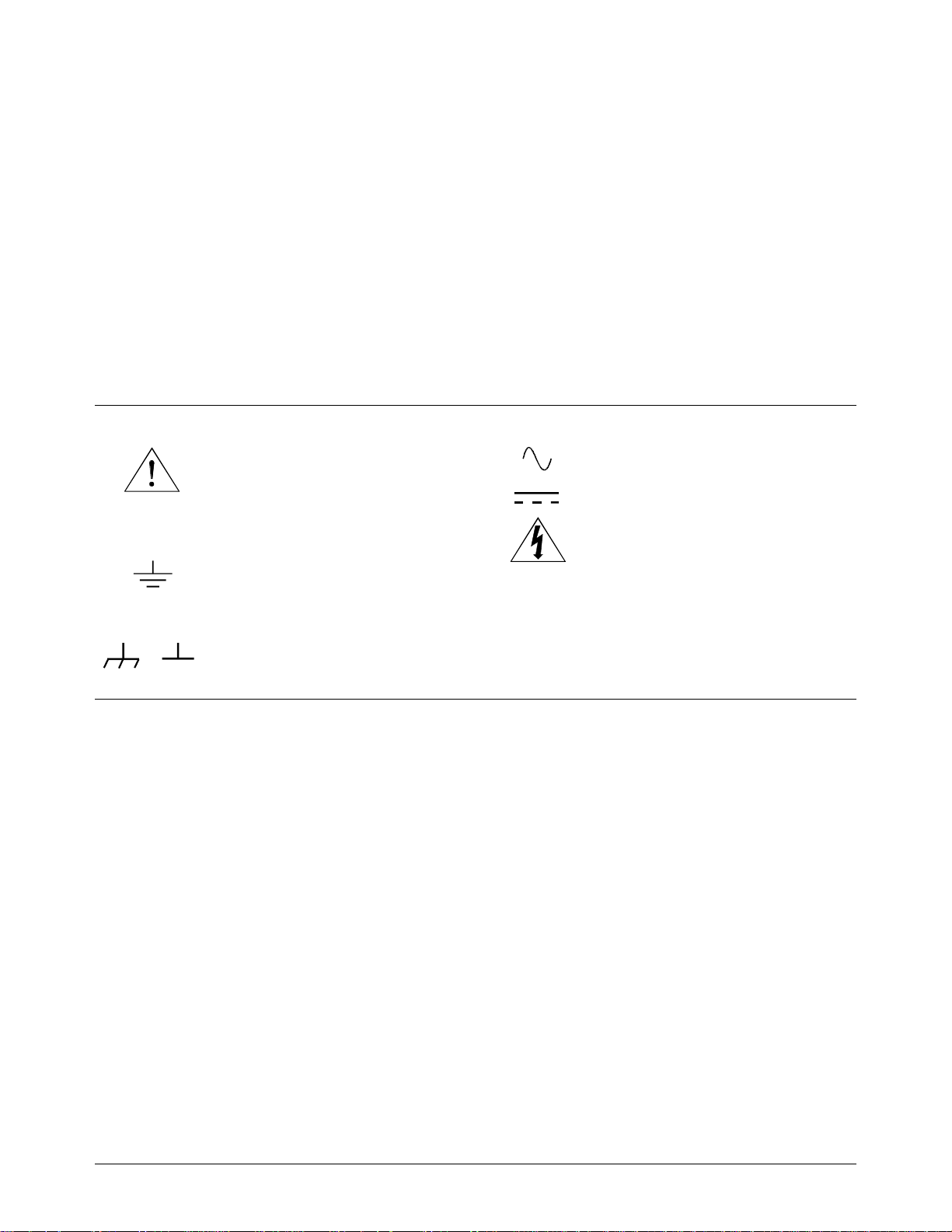
Safety Symbols
Instructi on manual sy mbol affixed to product.
Indic ates th at the user must refer to the manual for specific WARNING or CAUTION
informatio n to avoi d personal injury or damage to the pr oduct.
Alternating current (AC).
Direct current (DC).
Indicates t he field wir ing termina l that must
be connec ted to earth gr ound before op erating
the equipment—protects against electrical
shock in cas e of fa ul t.
or
Frame or chassis ground terminal—typically
connects to the equipment’s metal frame.
WARNING
CAUTION
Indicate s ha zardous volta ges.
Calls a tt ention to a procedure, practice, or condition that could cause bodi l y injury or death.
Calls attention to a procedur e, practice, or con dition that could possibly cause damage to
equipme nt or pe rm anent loss of dat a.
WARNINGS
The following general safety precautions must be observed during all phases of operation, service, and repair of this product.
Failure to comply w ith these precautions o r with spe cific warni ngs elsewher e in this ma nu a l violates safety s ta n d ar d s of desig n,
manufacture, and intended use of the product. Agilent Technologies assumes no liability for the customer’s failure to comply with
these re qu i rements .
Ground the equipment: For Safety Class 1 equipment (equipment having a protective earth terminal), an uninterruptible safety earth
ground must be provided from t he m ains power sour ce to the product i nput wiring term i nal s or supplied pow er cable.
DO NOT operate the pr od uct in an expl osive atmosp here or in th e presence of flammabl e gases or fum es.
For continued protection against fire, replace the line fuse(s) only with fuse(s) of the same voltage and current rating and type.
DO NOT use re pai red fuses or sho rt-c ircuited fuse holders.
Keep away fr om live circuits: Ope ra t in g personnel must not rem ove equipme nt cove rs or s hi el ds. Procedures i nvol vi ng the removal of
covers or shields are for use by service-trained personnel only. Under certain conditions, dangerous voltages may exist even with the
equipmen t switch ed off. To avoid da ngerou s elec trica l shoc k, DO NO T perform proced ures i nvolv ing cove r or shield re mova l unle ss you
are qualified to do so.
DO NOT operate damaged equipment: Whenever it is possible that th e safety protectio n features built into this product have been
impaired, either through physical damage, excessive moisture, or any other reason, REMOVE POWER and do not use the product until
safe oper at i on can be ve ri fied by serv i ce -t ra i ned personn el . If necess ar y, return th e product to an Agilent Technologies Sales a nd Service
Office for service and repair to ensure that safety features are maintained.
DO NOT serv ice or adjust al one: Do not at tempt inte rnal ser vice or adjus tment unles s anot her per son, ca pabl e of renderi ng first aid and
resuscitation, is present.
DO NOT substitute parts or modify equipm ent: Because of the danger of introducing additional hazards, do not install substitute parts
or perform any unauthorized modification to the product. Return the product to an Agilent Technologies Sales and Service Office for
service and repair to ensure that safety features are maintained.
4 Agilent E1463A 32-Channel, 5-Amp, Form C Switch Module Service Manual

DECLARATION OF CONFORMITY
According to ISO/IEC Guide 22 and CEN/CENELEC EN 45014
Manufacturer’s Name:
Agilent Technologies, Incorporated
Manufacturer’s Address: Measurement Product Generation Unit
815 14th ST. S.W.
Loveland, CO 80537 USA
Declares, that the product
Product Name:
Model Number:
32 Channel Form C VXI Switch
E1463A
Product Options: This declaration covers all options of the above product(s).
Conforms with the following European Directives:
The product herewith complies with the requirements of the Low Voltage Directive 73/23/EEC and the EMC Directive 89/336/EEC
and carries the CE Marking accordingly
Conforms with the following product standards:
EMC Standard
IEC 61326-1:1997+A1:1998 / EN 61326-1:1997+A1:1998
CISPR 11:1997 +A1:1997 / EN 55011:1998
IEC 61000-4-2:1995+A1:1998 / EN 61000-4-2:1995
IEC 61000-4-3:1995 / EN 61000-4-3:1995
IEC 61000-4-4:1995 / EN 61000-4-4:1995
IEC 61000-4-5:1995 / EN 61000-4-5:1995
IEC 61000-4-6:1996 / EN 61000-4-6:1996
IEC 61000-4-11:1994 / EN 61000-4-11:1994
Limit
Group 1 Class A
4kV CD, 8kV AD
3 V/m, 80-1000 MHz
0.5kV signal lines, 1kV power lines
0.5 kV line-line, 1 kV line-ground
3V, 0.15-80 MHz
I cycle, 100%
[1]
Canada: ICES-001:1998
Australia/New Zealand: AS/NZS 2064.1
Safety
IEC 61010-1:1990+A1:1992+A2:1995 / EN 61010-1:1993+A2:1995
Canada: CSA C22.2 No. 1010.1:1992
UL 3111-1:1994
Supplemental Information:
[1]
The product was tested in a typical configuration with Agilent Technologies test systems.
September 5, 2000
Date Name
Quality Manager
Title
Authorized EU-representative: Agilent Technologies Deutschland GmbH, Herrenberger Straβe 130, D 71034 Böblingen, Germany
For further information, please contact your local Agilent Technologies sales office, agent or distributor.
Agilent E1463A 32-Channel, 5-Amp, Form C Switch Module Service Manual 5

Notes
6 Agilent E1463A 32-Channel, 5-Amp, Form C Switch Module Service Manual

Notes
Agilent E1463A 32-Channel, 5-Amp, Form C Swit ch Module Service Manual 7

Notes
8 Agi lent E1463A 32- Channel, 5-Amp, Form C Sw itch Module Ser vice Manual
Introduction
Chapter 1
General Info rmation
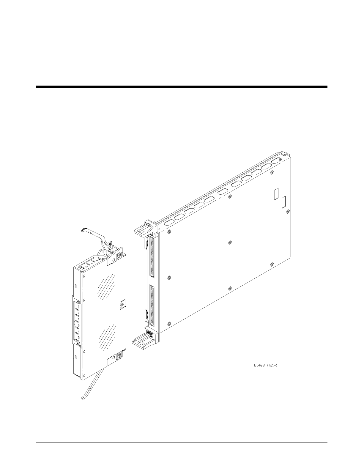
This manual contains inform at ion required to test, trouble shoot, and repai r
the Agilent E1463A 32-Channel Form C Switc h Module (see Figure 1-1).
Figure 1-1. Agilent E1463A Form C Switch
Chapter 1 General Information 9

Relay Life
Electromechanical relays are subject to normal wear-out. Relay life
depends on several factors. The effects of loading and switching
frequency are briefly discussed below:
Relay Load. In gen eral, hi ghe r powe r switching reduces relay life . In
addition, capa c it ive /inductive loa ds a nd hi gh inrush currents (e .g ., whe n
turning on a lam p or motor) reduce relay l ife . Exceeding the specified
maximum inputs can cause catastrophic failure.
Switching Frequency. Relay contacts he at up whe n switched. As the
switching frequency increases, the contacts have less time to dissipate heat.
The resulting increase in contact temperature reduces relay life.
End-of-Life
Detection
A preventive maintenance routine can prevent problems caused by
unexpected rela y f ai lu re. The en d of the li fe of a rela y c an be determined
using one or more of the thr e e methods described bel ow. T he best me thod
(or combination of methods), as well as the failure criteria, depends on the
applicatio n in which the relay is used.
Contact Resistance. As the relay begins to wear out, its c ont act resistance
will increase. When the resistance exceeds a pre-determined value, the relay
should be replaced. Typically, a relay should be replaced when the contact
resistance exce eds 2.0 Ohm.
Stability of Co nt ac t Resistance. The stability o f the co ntac t res ista nce
decreases with age. Using this method, the contact resistance is
measured several (5-10) times, and the variance of the measurements is
determined. An increase in the variance indicates deteriorating
performance.
Number of Operations. Alternatively, relays can be replaced after a
predetermined number of contact closures. How ever, this method
requires knowledge of the applied load and life specifications for the
applied load. For the Agilent E1463A, maximum relay life is specified
at 5 X 10
worst-case rated load.
7
operations with no load and 3.5 X 10⁴ operations at the
10 General Information Chapter 1

Replacement
Strategy
The replacement strategy also depends on the a pplication. If some
relays are used more often, or a t higher load, tha n the others, the relays
can be individually replaced as needed. If all of the relays see similar
loads and switching frequencies, the entire circuit boar d can be
replaced when the end of life a pproaches. The sensitivity of the
application should be weighed against the cost of replacing relays with
some useful life remaining.
NOTE
Relays that wear out normally or fail due to misuse should not be
considered defective and are not covered by the product’s warranty.
Safety Considerations
This pr oduct is a Saf e ty Class I instrument tha t is provided with a
prote ctive earth t e r minal when installed in th e ma inframe. Th e
instrument, mainf rame, a nd a ll r e la ted docu me ntation sho uld be revie wed
for familiarization with safety markings and instructions before operation
or service.
Refer to the WARNI NGS on pag e 4 i n thi s ma nual for a summary of safe ty
informatio n. Safety informat ion for testing a nd se rvice follows and is al so
found throughout this manual.
WARNINGS and
CAUTIONS
This section co nta i ns W A RNINGS which must be foll owe d f or your
protection and C AUTIONS whi ch must be follo w ed to a voi d da ma ge to t he
equipment when performing instrument maintenance or repair.
WARNING
SERVICE-TRAINED PERSONNEL ONLY. The information in this
manual is for service-trained personnel who are familiar with
electroni c circ u it ry and are aware of th e haz ards involved. To
avoid personal injury or damage to the instrument, do not
perform procedures in this manual or do any servic ing unless
you are qualified to do so.
CHECK MAINFRAME POWER SETTINGS. Before applying
power, verify that the main frame setting matches the line
voltage and that the correct fuse is installed. An uninterruptible
safety earth ground must be provide d from the main power
source to the supplied power cord set.
Chapter 1 General Information 11

WARNING
GROUNDING REQUIREMENTS . Interruption of the protective
(grounding) conductor (inside or outside the mainframe) or
disconnecting th e protective earth terminal will cause a
potential shock hazard that coul d result in personal injury.
(Grounding one conductor of a two-conductor outlet is not
sufficient protection.)
IMPAIRED PROTECTION. Whene ve r it is likely tha t inst ru ment
protection has been impaired, the mainframe must be made
inoperative and b e secured against any un intended operation.
REMOVE POWER IF POSSIBLE. Some procedures in this
manual may be performed with power supplied to the
mainframe while p rotective covers ar e removed. Energy
available at many points may, if contacted, result in personal
injury. (If maintenance can be performed without power
applied, the power should be removed.)
USING AUTOTRANSFORMERS. If the mainframe is to be
energized via an autotransformer (for voltage reduction) make
sure the common terminal is connected to neutra l (tha t is, the
grounded sid e of the main’s supply).
CAPACITOR VOLTAGES. Capacitors inside the mainframe
may remain charged even when the mainframe has been
disconnected from its source of supply.
USE PROPER FUSES. For continued protection ag ainst fire
hazard, rep lace th e line fuses only with fuses of the same
current rating and type (such as normal blow, time delay, etc.).
Do not use repaired fuses or short -circui ted fuseholders.
SHOCK HAZARD. Only service-trained personnel who are
aware of the hazards involved should install, remove, or
configure the Agilent E1463A 32-Cha nnel Form C Switch
Module . Before you remove any installed modul e, disconnect
AC power from the mainframe and from other modules that
may be connecte d to the Switch Module.
CHANNEL WIRING INSULATION. All channels that have a
common connection must be insulated so that the user is
protected from electrical shock. This means wiring for all
channels must be insulated as thoug h each channel carries
the voltage of the highest voltag e chann el.
12 General Information Chapter 1

CAUTION
MAXIMUM INPUTS. The maximum voltage that can be applied to
any terminal is 125 V dc (250 Vac rms). The maximum current per
channel or common is 5 A DC or ac rms. The maximum power that
can be applied to any channel or common is 150 W or 1250 VA.
STATIC ELECTRICITY. Static electricity is a major cause of
component failure. To prevent damage to the electrical components
in the Switch Module, observe anti-static techniques whenever
working on the device.
Inspection/Shipping
This section contains init ia l ( incoming) ins pe ct io n an d shi pping guideline s
for the switch module.
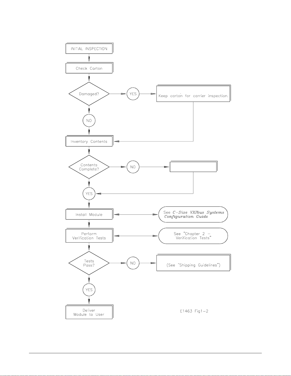
Initial Inspection Use the steps in Fi gure 1- 2 as guidelines to per fo rm initial inspe c ti on of one
of the modules. Ve ri fic a ti on Te sts are optional.
WARNING
To avoid possible hazardous electri cal shoc k, do not perform
elec t rical tests if there are signs of shipping d amage t o the
shipping container or to the instrument.
Chapter 1 General Information 13
Notify Agilent and Carrier.
Notify Agilent
Return Module to Agilent
Figure 1-2. Initial (Incoming) Inspection Guidelines
14 General Information Chapter 1
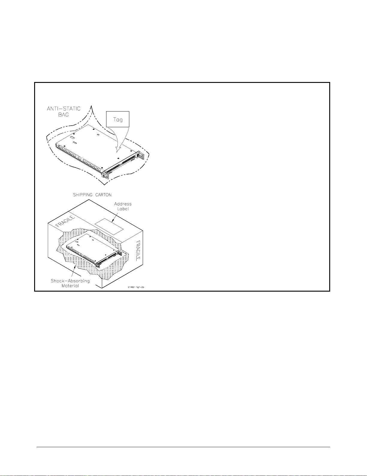
Shipping
Guidelines
Follow the steps in Figure 1-3 to retur n t he Module to an Agilent
Technologies Sales and Support Office or Service Center.
1 Prepare the Module
• Remove user wiring from terminal module
• Attach tag to module/pod that identifies
- Owner
- Model Number/Serial Number
- Service Required
• Place tagged device in approved anti-static bag
2 Package the Module
• Place packaged Module in shipping carton*
• Place 75 to 100 mm (3 to 4 inches) of shock-
absorbing material around the Module
• Seal the shipping carton securely
• Mark the shipping carton FRAGILE
3 Ship the Module to Agilent Technologies
• Place address label on shipping carton
• Send carton to Agilent Technologies
Figure 1-3. Packaging/Shipping Guidelines
* We reco m m end that you use t he s am e shipping ma t er ia l s as those used in factory packa gi ng (available fr om A gi l ent T echnologies ).
For other (com m ercially-av ailable) ship pi ng materials , us e a d oubl e wa l l- carton with mi ni mum 2.4 MPa (3 50 ps i) te st .
Chapter 1 General Information 15
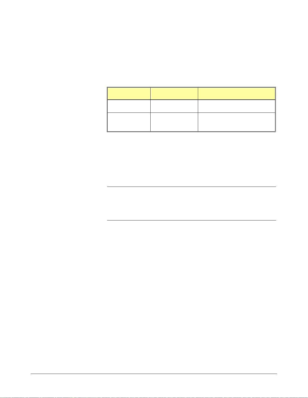
Environment
The recommended operating environmen t for the Agilent E1463A 32-Channel
Form C Switch Module is:
Environment Temperature Humidity
Operating 0oC to +55oC <65% relative (0oC to +40oC)
Storage and
Shipment
Switch Module Description
The Agilent E1 463A 32-Channel Form C Switch Module is an "instrument "
in the slots of a VXIbus mainf r ame . E ach m odule is assigned an error
queue, input and output buffers, and a sta tu s regi ster.
NOTE
Agilent E1463A
Description
Instruments are based on the logical addresses of the plug-in modules. See
the C-Size VXIbus Systems Configuration Guide to set the addresses to
create an instrument.
The Agilent E1463A 32-Channel Form C Swit c h Module is a VXI-bus
C-Size register bas ed produc t. The Form C Switch Modul e prov ide s 32
channels of Form C rel a y swit c hing. Each channel includes a Comm on ( C),
a Normally Open (NO) an d a Normally Clos ed (NC) term i nal. E ach rel ay
can switch up to 5 amps.
o
-40
C to +75oC <65% relative (0oC to +40oC)
The channels ca n be indi vi dua lly controlled or ca n be scann ed . Eac h
channel uses a non- latching rel ay and al l c ha nne l Commons (C) are
connected to the Normally Closed (NC) terminals following a power
ON or a reset command.
Pads are provide d on the compo ne nt a sse mbly for the i nstallation of us er
provided protec ti on c irc uitry. The termi na l mo dule contains screw ter mi na ls
for user wiring connecti ons.
16 General Information Chapter 1

Switch Module
Specifications
Specification s are listed in Appendix A of the Agilent E1463A 32-Channel
Form C Switch Module User’s Manual. These specifications are the
performance standards or limits against which the modules may be tested.
Switch Module
Serial Numbers
Devices covered by this manual are identified by a serial number prefix
listed on the title page. Agilent Technologies uses a two-part serial number
in the form XXXXAYYYYY, where XXXX is the serial prefix, A is the
country of origin (A=USA), and YYYYY is the serial suffix. The serial
number prefix identifies a series of identical instruments. The serial number
suffix is assigned sequentially to each instrument. The serial number plate is
located on the right-hand shield near the backplane connectors.
Switch Module
Options
The Agilent E1 463A c om es sta ndar d with a terminal module consisting of
screw terminals. In addition , a ter mi na l module with solder eye termin al s is
available (Option A3G).
Sche mati cs an d
Component
Component locators and schematics for the modules are packaged with this
manual. Clear plastic sleeves are included for storage.
Locators
Recommended Test Equipment
Table 1-1 list s the te st equipment rec omm e nde d f or te sti ng a nd se r vicing the
module. Essential requirements for each piece of test equipment are
described in the Re qui r em e nts col umn.
Table 1-1. Reco mmended Test Equipment
Instrument Requirements Recommended Model Use*
Controller, GPIB GPIB compatibility as defined by IEEE
Standard 488-1988 and the iden tical
ANSI Standard MC1.1: SH1, AH1, T2,
TE0, L2, LE0, SR0, RL0, PP0, DC0,
DT0, and C1, 2, 3, 4, 5.
Mainframe Compatible with switch module Agilent E1401B/T or
Command Module Compatible with switch module Agilent E1405A/B or
Digital Multimeter 4-wire ohms
2-wire ohms (up to 1 GΩ )
HP 9000 Series 300
or
IBM Compatible PC with
BASIC
Agilent E1421B
Agilent E1406A
Agilent 3458A or
Agilent 34401A
F,O,
P,T
F,O,
P,T
F,O,
P,T
O,P, T
* F = Functiona l Verification Tests, O = Operat i on V er ification Tes t s, P = Per formance Verific at i on T e st s, T = Troublesho oting
Chapter 1 General Information 17

Notes
18 General Information Chapter 1

Introduction
Chapter 2
Verification Tests
The three levels of te st procedures described in this chapt e r ar e us ed to
verify that the Agilent E1463A 32 -Cha nne l Form C Switch Module:
• is fully functional (Functional Verification)
• meets selected testable specifications (Operation Verification)
• meets all testable specifications (Performance Verification)
Test Conditions
and Procedures
Performance Test
Record
Verification Test
Examples
See Table 1-1 for test e quipment require me nt s. You should complet e th e
Performance Verificati on tests at least once a year. Fo r hea vy us e or se ver e
operating e nv ironm e nts, pe r f orm the tests mor e often.
The verification tests assume that the person performing the tests
understands how t o ope r ate the ma inframe, the switc h module, and specified
test equipme nt. The te st procedures do not specify equip ment settings for
test equipment, except in general terms. It is assumed that a qualified,
service-trained technician will select and connect the cables, adapters, and
probes required for the test.
o
It is assumed that the temperature is no greater than 25
humidity is no gre a ter than 40% .
The results of each Performance Verification test may be recorded in the
Performance Test Re c ord (T ab le 2- 1) .
Each verification test procedure includes an example program that performs
the test. All example programs assume the following:
C and the rela tive
• Controller is an HP 9000 Series 200/300 computer
• Programming languag e is BAS IC
• Switch address is 70915
• Switch card number is 1
Chapter 2 Verification Tests 19

Switch Module Functional Verification
The Functional Verification Test for the Agilent E1 463A 32-Channel Form C
Switch Module consists of sending the
This test can be used at any time to verify that the device is connected properly and
is responding to ba sic com m ands.
Procedure 1. Verify that the Switch Module is installed in the mainframe and that
the mainframe has passed its power-on test.
2. Send the *TST? command to the device (see example following).
3. The device will return an error code . Any non-z e ro error cod e
indicates a self - te st failure. See Table 4-4 for a desc r ip tion of self-test
error codes.
Example An example follow s w hic h uses an HP 9000 Serie s 300 computer with BA S IC a nd
a Switch Module ad dre s s of 70915.
10 OUTPUT 70915;"*TST?" Send the self-test command
20 ENTER 70915;A Get response
30 PRINT A
40 END
*TST? command and checking the resp o nse.
Operation Verification
The procedure s in th is sec ti on a re used to provide a high degree of confi dence that
the Switch Modul e is me e ti ng published specific a ti ons . The O pe ration Verifica tion
tests are usually a su bset of th e Performance V e rification tests and a re suitable for
checkout aft er per forming repairs.
For the Agilent E1463A Switch Module, Operatio n Verification is performed by
completing the Closed Channel Resistance Test as described in the Performance
Verificatio n te st procedures (Tes t 2-1 ). Thi s te st is usually sufficient t o ve rif y tha t
the instr ument is meeting its specifications.
Performance Verification
The procedures in this section are used to test the module’s electrical performance
using the specific a ti ons in Ap pe ndi x A of the Agilent E1463A 32-Channel Form C
Switch Module User’s Manual as the performance standards.
20 Verification Tests Chapter 2

The performance verification tests have two parts: a closed channel resistance te st of all
relay contacts (Test 2-1) and a DC isolation test (Test 2-2). T hese tests a re sufficient t o
determine that the module is ope rat ing within sp ecificat ions. These te sts are sui table for
incoming inspection, troubleshooting, and preventive maintenance.
Wiring the Test
Fixture
A test fixture is required for the performance veri fic a ti on t ests. Figure 2-1 shows
typical connections using an Agil en t E 1463A terminal mod ule for the test fixture .
You may want to or de r an extra terminal mo dule to use as a test fixture , so yo u
don’t have to re-wire each time t he te sts are pe rformed. The A gilent E1463A
terminal module part number is E 1463-80011 (for mo dul es w ith s er ia l nu mbers
prior to 3126A01817, the terminal module part numbe r is E1 463-80001).
Figure 2-1. Agilent E1463A Test Fixture
Test 2-1:
Closed Channel
Resistance Test
This test verifies that all relay contacts meet the closed-channel resistance speci- fication
for the module. When making the Closed Channel Resistance Test, the NO and NC paths
relay contacts are tested independently. This test uses the test fixture (see Figure 2-1).
The Closed Channel resistance specification for each relay contact is 2.0 W
.
Common to NO
Measurements
1. Make Hardware Connections
• Turn mainframe power OFF
• Connect DMM le ad s as sho w n in Fi gure 2-2
Chapter 2 Verification Tests 21

• Set DMM to measure 4-wire Ohms
• Turn mainframe power ON
2. Measure Channel 0 C to NO Resistance
• Send *RST to Module
• Send CLOS (@nn00) to close channel 0, where nn = card #
(typically 01)
• Trigger the DMM with TRIG SGL and note reading
• Send OPEN (@nn00) to open channel 0, where nn = card #
(typically 01)
• Enter the result in Table 2-1 for channel 0 C to NO
3. Repeat for Channels 1 through 31 C to NO
• Repeat step 2 for channe ls 1 through 31
• Use OPEN (@nncc) and CLOS (@nncc), where nn = card # and
cc = channel # (omit leading zeroes in nn)
Figure 2-2. Common to NO Test Connections
Channel 0 C to NC
Measurements 1. Make Hardware Connections
• Turn mainframe power OFF
22 Verification Tests Chapter 2

• Set DMM to measure 4-wire Ohms
• Connect DMM leads as sh own in Figure 2-3
• Turn mainframe power ON
2. Measure Channel 0 C to NC Resistance
• Send *RST to Module
• Send CLOS (@nn00:nn31) to close all channels, where nn = card
# (typicall y 01)
• Send OPEN (@nn00) to open channel 0, where nn = card #
(typically 01)
• Trigger the DMM with TRIG SGL and note reading
• Enter the result in Table 2-1 for Channel 0 C to NC
• Send CLOS (@nn00) to close channel 0, where nn = card #
(typically 01)
3. Repeat for Channels 1 through 31
• Repeat step 2 for channel 1 through 31 C to NC
• Use OPEN (@nncc) and CLOS (@nncc), where nn = card # and
cc = channel # (omit leading zeroes in nn)
Figure 2 -3. Common to NC Test Connections
Chapter 2 Verification Tests 23

Example: Closed
Channel Resistance
Test
This example per forms a Closed Ch annel Resistance Test t o measur e
Channels 0 th rough 31 relay contact resistances. If the rela y c ontact
resistance for a channel is >2.0
Ω the program prints a message indicating
which channe l h as failed the test. Use this list in Chapter 4 whe n
troublesho oting a failing rel a y.
NOTE
This test assumes that the module is configured without protection
varistors, fuses, or resistors and that jumpers JM1 through JM8 are
installed on the Agilent E1463A Component Assembly (factory setting).
Refer to the Agilent E1463A Use r’s Manual for details and locations of
user installed protection circuits
10! RE-SAVE "CLOS_TEST"
20 ASSIGN @Dmm TO 722
30 ASSIGN @Sw TO 70915
40 DISP CHR$(129)
50 DIM Result(1,31),Path$(1)[2]
60 DATA NO,NC
70 READ Path$(*)
80 Cc$="01" ! Card number
90 Ph$="0" ! Place holder
100 !
110 !Start test
120 !
130 CLEAR SCREEN
140 PRINT "Install Component Assembly and Test Fixture "
150 PRINT
160 PRINT " 1. Turn Mainframe and Agilent 3458A DMM power OFF"
170 PRINT " 2. Connect GPIB Cable between mainframe and DMM"
180 PRINT " 3. Install E1463A Component Assembly into Mainframe"
190 PRINT " 4. Attach Test Fixture to Component Assembly"
200 PRINT " 5. Turn Mainframe and DMM power ON "
210 PRINT " 5. Press Continue when ready to begin testing "
220 PAUSE
230 CLEAR SCREEN
240 !
250 ! Start the measurements
260 !
270 FOR J = 0 TO 1
280 OUTPUT @Dmm;"PRESET NORM;FUNC OHMF"
(Continued on Next Page)
24 Verification Tests Chapter 2

290 OUTPUT @Sw;"*RST"
300 OUTPUT @Sw;"*OPC?"
310 ENTER @Sw;Opc
320 IF Opc<>1 TH EN GOTO 300
330 IF J=1 THEN
340 OUTPUT @Sw;"CLOS (@"&Cc$&"00:"&Cc$&"31)"
350 END IF
360 PRINT TABXY(1,1), "Channels 00-31 "&Path$(J)&
" measurements"
370 PRINT TABXY(1,3), "1. Connect DMM Sense and Input HI leads
to test fixture "&Path$(J)
380 PRINT TABXY(1,4), "2. Connect DMM Sense and Input LO leads
to test fi x t u r e C"
390 DISP "Press Continue when connections are complete"
400 PAUSE
410 CLEAR SCREEN
420 OUTPUT @D mm;"TRIG SGL"
430 ENTER @Dmm;Meas
440 IF Meas <1.E+6 THEN
450 PRINT "Stuck relay found"
460 PRINT "Repair problem and re-run test"
470 STOP
480 END IF
490 FOR I=0 TO 31
500 IF J<1 THEN
510 IF I <10 THEN
520 OUTPUT @Sw;"CLOS (@"&Cc$&Ph$&VAL$(I)&")"
530 ELSE
540 OUTPUT @Sw;"CLOS (@"&Cc$&VAL$(I)&")"
550 END IF
560 ELSE
570 IF I <10 THEN
580 OUTPUT @Sw;"OPEN (@"&Cc$&Ph$&VAL$(I)&")"
590 ELSE
600 OUTPUT @Sw;"OPEN (@"&Cc$&VAL$(I)&")"
610 END IF
620 END IF
630 OUTPUT @Sw;"*OPC?"
640 ENTER @Sw;Opc
650 IF Opc<>1 THEN GOTO 630
660 OUTPUT @Dmm;"TRIG SGL"
670 ENTER @Dmm;Result(J,I)
(Continued on Next Page)
! Check for stuck relays
Chapter 2 Verification Tests 25

680 IF J<1 THEN
690 IF I <10 THEN
700 OUTPUT @Sw;"OPEN (@"&Cc$&Ph$&VAL$(I)&")"
710 ELSE
720 OUTPUT @Sw;"OPEN (@"&Cc$&VAL$(I)&")"
730 END IF
740 ELSE
750 IF I <10 THEN
760 OUTPUT @Sw;"CLOS (@"&Cc$&Ph$&VAL$(I)&")"
770 ELSE
780 OUTPUT @Sw;"CLOS (@"&Cc$&VAL$(I)&")"
790 END IF
800 END IF
810 OUTPUT @Sw;"*OPC?"
820 ENTER @Sw;Opc
830 IF Opc<>1 T H EN GOTO 8 1 0
840 IF Result(J,I)<0 THEN Result(J,I)=0
850 IF Result(J,I)>2.0 THEN
860 PRINT "Resistance for Channel ";I;" "&Path$ (J)&" conta cts
is >2.0 Ohms"
870 END IF
880 NEXT I
890 PRINT "Measurements complete for Channel 00-31 "&Path$(J)&" contacts"
900 IF J<1 THEN
910 DISP "Press Continue for cha nnels 00- 31 N or ma lly Closed
measurements"
920 PAUSE
930 END IF
940 NEXT J
950 PRINT "Closed Contact Resistance measurements complete"
960 DISP "Press continue to print measu rement results"
970 PAUSE
980 CLEAR SCREEN
990 !
1000 ! Print measurement results
1010 !
1020 Format:IMAGE "CH ",DD,3X,DD.DDDD," Ohms",3X,DD.DDDD," Ohms"
1030 PRINT TABXY(1,3)," NO Contacts NC Contacts"
1040 PRINT
1050 FOR I=0 TO 31
1060 PRINT USING Format;I,Result(0,I),Result(1,I)
1070 NEXT I
1080 END
26 Verification Tests Chapter 2

Typical Result
NO Contacts NC Contacts
CH 0 .1453 Ohms .1453 Ohms
CH 1 .1616 Ohms .1661 Ohms
CH 2 .1914 Ohms .1948 Ohms
CH 3 .3491 Ohms .2657 Ohms
CH 4 .4644 Ohms .2628 Ohms
CH 5 .1226 Ohms .1389 Ohms
CH 6 .1499 Ohms .1678 Ohms
CH 7 .1547 Ohms .1817 Ohms
CH 8 .3347 Ohms .2257 Ohms
CH 9 .4932 Ohms .3096 Ohms
CH 10 .157 2 O hms .1849 O hms
CH 11 .183 6 O hms .2106 O hms
CH 12 .154 3 O hms .1317 O hms
CH 13 .286 1 O hms .2144 O hms
CH 14 .450 0 O hms .2722 O hms
CH 15 .136 6 O hms .1771 O hms
CH 16 .169 4 O hms .1639 O hms
CH 17 .184 8 O hms .1569 O hms
CH 18 .375 3 O hms .2373 O hms
CH 19 .550 8 O hms .2952 O hms
CH 20 .129 5 O hms .1257 O hms
CH 21 .164 8 O hms .1328 O hms
CH 22 .183 9 O hms .1438 O hms
CH 23 .360 9 O hms .2349 O hms
CH 24 .450 0 O hms .2808 O hms
CH 25 .173 3 O hms .1507 O hms
CH 26 .211 5 O hms .1723 O hms
CH 27 .236 2 O hms .1876 O hms
CH 28 .280 8 O hms .1874 O hms
CH 29 .414 0 O hms .2340 O hms
CH 30 .169 2 O hms .1412 O hms
CH 31 .182 2 O hms .1833 O hms
Chapter 2 Verification Tests 27

Test 2-2:
DC Isolation Test
This test veri fie s tha t sufficient DC iso la ti on e x i sts at various point s on the
Module. DC Isolation is checked from NO to NC, NO to Chassis, and NC to
Chassis. This test uses the test fixture (see Figure 2-1).
NOTE
The DMM used should be capable of measuring at least 1 G
DMM indicates an overload, record the reading as >Rmax, where Rmax is
the highest resistance that the DMM can measure. For example, if the
DMM is an Agilent 3458A, a typical return for an overload is 1.E+38 and
the entry in Table 2-1 should be >1.2 G
Ω..
NC (&C) to NO Isolation 1. Make hardware connections as sho wn in F igure 2-4
2. Set DMM to 2-wire ohms, 1 G Ω range
3. Send *RST to Module
4. Trigger the DMM with TRIG SGL
5.
Record the DMM reading in Table 2-1 (NC to NO)
Ω.. If the
Figure 2-4. NC to NO Isolation
28 Verification Tests Chapter 2

NC (&C) to Chassis
Isolation 1. Make hardware connections a s shown in Figure 2-5
2. Set DMM to 2-wire ohms, 1 G Ω range
3. Send *RST to Module
4. Trigger the DMM with TRIG SGL
5.
Record the DMM reading in Table 2-1 (NC to Chassis)
Figure 2-5. NO and NC to Chassis Isolation
NO (&C) to Chassis
Isolation 1. Make hardware connections a s shown in Figure 2-5
2. Set DMM to 2-wire ohms, 1 G Ω range
3. Send *RST to Module
4. Send CLOS (@100:131) to Module to close all channels
5. Trigger the DMM with TRIG SGL
6.
Record the DMM reading in Table 2-1 (NO to Chassis)
Chapter 2 Verification Tests 29

Example: DC Isolation
Test
This example performs DC Isolation Tests for C to chassis and NO to NC.
10! RE-SAVE "DC_ISOL"
20 ASSIGN @Dmm TO 722
30 ASSIGN @Sw TO 70915
40 DISP CHR$(129)
50 Cc$="01" ! Card number
60 DIM Result(2)
70 PRINT "Equipment Connections "
80 PRINT
90 PRINT " 1. Turn Mainframe and Agilent 3458A DMM power OFF"
100 PRINT " 2. Connect GPIB Cable between mainframe and DMM"
110 PRINT " 3. Install E1463A Component Assembly into Mainframe "
120 PRINT " 4. Attach Test Fixture to Component Assembly"
130 PRINT " 5. Turn Mainframe and Agilent 3458A power ON"
140 DISP "Press Continue when ready to begin testing "
150 PAUSE
160 OUTPUT @Dmm;"OHM 1E9"
170 CLEAR SCREEN
180 !
190 ! Measure DC isolation (NC to NO)
200 !
210 OUTPUT @Sw;"*RST"
220 OUTPUT @Sw;"*OPC?"
230 ENTER @Sw;Opc
240 IF Opc <>1 THEN GOTO 220
250 PRINT TABXY(1,1),"NC (&C) to NO DC Isolation "
260 PRINT TABXY(1,3),"1. Connect DMM Input HI lead to test fixture NO"
270 PRINT TABXY(1,4),"2. Connect DMM Input LO lead to test fixture C"
280 DISP " Press Continue when connections are complete"
290 PAUSE
300 OUTPUT @Dmm:"TRIG SGL"
310 ENTER @Dmm;Result(0)
320 CLEAR SCREEN
330 PRINT TABXY(1,1),"NC (&C) to Chassis DC Isolation"
340 PRINT TABXY(1,3),"1. Connect DMM Input HI lead to Chassis"
350 PRINT TABXY(1,4),"2. Connect DMM Input LO lead to test fixture C"
360 DISP " Press Continue when connections are complete"
370 PAUSE
380 OUTPUT @Dmm;"TRIG SGL"
390 ENTER @Dmm;Result(1)
(Continued on Next Page)
30 Verification Tests Chapter 2

400 CLEAR SCREEN
410 PRINT TABXY(1,1),"NO (&C) to Chassis DC Isolation"
420 DISP " Press Continue to make measurement"
430 PAUSE
440 OUTPUT @Sw;"CLOS (@"&Cc$&"00:"&Cc$&"31)"
450 OUTPUT @Sw;"*OPC?"
460 ENTER @Sw;Opc
470 IF Opc <>1 THEN GOTO 450
480 OUTPUT @Dmm;"TRIG SGL"
490 ENTER @Dmm;Result(2)
500 OUTPUT @Sw;"*RST"
510 PRINT "DC Isolation tests complete"
520 DISP "Press Continue to print measurement results"
530 PAUSE
540 CLEAR SCREEN
550 PRINT TABXY(1,1),"DC Isolation Tests"
560 PRINT TABXY(1,3),"NC to NO (Ohms) ";Result(0)
570 PRINT TABXY(1,4),"NC to Chassis (Ohms) ";Result(1)
580 PRINT TABXY(1,5),"NO to Chassis (Ohms) ";Result(2)
590 END
!Close all channels
Typical Result
DC Isolation Tests
NC to NO (Ohms) 1E+38
NC to Chassis (Ohm s) 1E+38
NO to Chassis (Ohm s) 1E +38
Performance Test Record
Table 2-1 is a form you can copy and use to record performance
verification test results for the Switch Module. Information
concerning test limits, measurement uncertainty, and test accuracy
ratio (TAR) is provided below.
Test Limits Test limits a r e d e f i n e d f or Closed Cha n ne l Resistan c e Test and DC
Isola tion Test using the spe c ificatio ns in Appen dix A of the Agilent
E1463A 32-Channel Form C Switch Module User’s Manual. The
speci f ic a tions are single-sided, (i.e . , there is an upper limit or a lower
limit, bu t not both). I n the Perfor ma n c e Test Record, the Minimum o r
Maximum column wi ll be blank.
Chapter 2 Verification Tests 31

Measurement
Uncertainty
For the performance verification tests in this manual, measurement
uncertainties a r e ca lculated based on th e Agile nt 3458A Digital Mu ltimeter.
The measurement uncertainty shown in Table 2-1 is the accuracy of the
Agilent 3458A usi ng 90-day specific a ti ons. The c alc ula tions follow.
Closed Channel
Resistance Test
Conditions:
• 4-wire ohms fu nction , 10 Ω range
• 90-day specifications
• Worst-case reading = 2.0 Ω
M.U. = (15 ppm of Reading + 5 ppm of Range)
= (15x10
= 8.0x10
DC Isolation Test Conditions:
• 2-wire ohms fu nction , 1 G Ω range
• 90-day specifications
• Worst-case reading = 1.2 G Ω (highest resistance that can be measured
with the Agilent 3458A)
M.U. = (0.5% of Reading + 10ppm of Range)
= (0.005 * 1.2x10
= 6.1x10
Test Accuracy
Ratio (TAR)
Test Accuracy Ratios are not defined for single-sided measurements, so all
measurements ha ve "NA" (N ot Applicable) in the TAR co lum n.
-6
* 2.0) + ( 5x10-6 * 10) Ω
-5
Ω
6
Ω
9
) + ( 10x10
-6
* 1x109) Ω
32 Verification Tests Chapter 2

Table 2-1. Performance Test Record (P age 1 of 3)
Model _______________________ Report No. __________________________ Date __________
General Informati on
Test Facility:
Name ________ ____ _________________________
Address
_____________________________________
City/State _______________________ ____________
Phone _____________________________________
Special Notes:
___________________________________________________________________________________________ __
___________________________________________________________________________________________ __
___________________________________________________________________________________________ _
___________________________________________________________________________________________ _
___________________________________________________________________________________________ _
___________________________________________________________________________________________ __
Report No. _________________________________
Date _____________________________________
Customer ___________________________________
Tested by _______________________ ___________
Test Eq uipment R e c ord
Test Equipment Used:
Description
Model No. Trace No. Cal Due Date
1. _______________________________
2. _______________________________
3. _______________________________
4. _______________________________
5. _______________________________
_______________
_______________
_______________
_______________
_______________
_______________
_______________
______________
_______________
_______________
_______________
_______________
_______________
_______________
_______________
Chapter 2 Verification Tests 33

Table 2-1. Performance Test Record (P age 2 of 3)
Model _______________________ Report No. __________________________ Date __________
Test No/Descri ption Minimum*
Value
2-1. Contact Resistance Test (values in Ohms)
NO to C Resistance
Channel 00
Channel 01
Channel 02
Channel 03
Channel 04
Channel 05
Channel 06
Channel 07
Channel 08
Channel 09
Channel 10
Channel 11
Channel 12
Channel 13
Channel 14
Channel 15
Channel 16
Channel 17
Channel 18
Channel 19
Channel 20
Channel 21
Channel 22
Channel 23
Channel 24
___________________
___________________
___________________
___________________
___________________
___________________
___________________
___________________
___________________
___________________
___________________
___________________
___________________
___________________
___________________
___________________
___________________
___________________
___________________
___________________
___________________
___________________
___________________
___________________
___________________
Measured V alue Maximum
Value
2.0
2.0
2.0
2.0
2.0
2.0
2.0
2.0
2.0
2.0
2.0
2.0
2.0
2.0
2.0
2.0
2.0
2.0
2.0
2.0
2.0
2.0
2.0
2.0
2.0
Meas
Uncert
8.000E-5
8.000E-5
8.000E-5
8.000E-5
8.000E-5
8.000E-5
8.000E-5
8.000E-5
8.000E-5
8.000E-5
8.000E-5
8.000E-5
8.000E-5
8.000E-5
8.000E-5
8.000E-5
8.000E-5
8.000E-5
8.000E-5
8.000E-5
8.000E-5
8.000E-5
8.000E-5
8.000E-5
8.000E-5
Test Acc
Ratio (TAR)
NA
NA
NA
NA
NA
NA
NA
NA
NA
NA
NA
NA
NA
NA
NA
NA
NA
NA
NA
NA
NA
NA
NA
NA
NA
Channel 25
Channel 26
Channel 27
Channel 28
Channel 29
Channel 30
Channel 31
___________________
___________________
___________________
___________________
___________________
___________________
___________________
2.0
2.0
2.0
2.0
2.0
2.0
2.0
8.000E-5
8.000E-5
8.000E-5
8.000E-5
8.000E-5
8.000E-5
8.000E-5
NA
NA
NA
NA
NA
NA
NA
*Single-sided specification - Minimum value does not app ly
34 Verification Tests Chapter 2

Table 2-1. Performance Test Record (P age 3 of 3)
Model _______________________ Report No. ____________ ______________ Date __________
Test No/Descri ption Minimum*
Value
2-1. Contact Resistance Test (values in Ohms)
NC to C Resistance
Channel 00
Channel 01
Channel 02
Channel 03
Channel 04
Channel 05
Channel 06
Channel 07
Channel 08
Channel 09
Channel 10
Channel 11
Channel 12
Channel 13
Channel 14
Channel 15
Channel 16
Channel 17
Channel 18
Channel 19
Channel 20
Channel 21
Channel 22
Channel 23
Channel 24
___________________
___________________
___________________
___________________
___________________
___________________
___________________
___________________
___________________
___________________
___________________
___________________
___________________
___________________
___________________
___________________
___________________
___________________
___________________
___________________
___________________
___________________
___________________
___________________
___________________
Measured V alue Maximum
Value
2.0
2.0
2.0
2.0
2.0
2.0
2.0
2.0
2.0
2.0
2.0
2.0
2.0
2.0
2.0
2.0
2.0
2.0
2.0
2.0
2.0
2.0
2.0
2.0
2.0
Meas
Uncert
8.000E-5
8.000E-5
8.000E-5
8.000E-5
8.000E-5
8.000E-5
8.000E-5
8.000E-5
8.000E-5
8.000E-5
8.000E-5
8.000E-5
8.000E-5
8.000E-5
8.000E-5
8.000E-5
8.000E-5
8.000E-5
8.000E-5
8.000E-5
8.000E-5
8.000E-5
8.000E-5
8.000E-5
8.000E-5
Test Acc
Ratio (TAR)
NA
NA
NA
NA
NA
NA
NA
NA
NA
NA
NA
NA
NA
NA
NA
NA
NA
NA
NA
NA
NA
NA
NA
NA
NA
Channel 25
Channel 26
Channel 27
Channel 28
Channel 29
Channel 30
Channel 31
Test 2-2 DC Isolation (values in Ohms)
NO to NC
NC to Chassis
NO to Chassis
1.2E9
1.2E9
1.2E9
___________________
___________________
___________________
___________________
___________________
___________________
___________________
___________________
___________________
___________________
2.0
2.0
2.0
2.0
2.0
2.0
2.0
*6.1E6
8.000E-5
8.000E-5
8.000E-5
8.000E-5
8.000E-5
8.000E-5
8.000E-5
6.1E6
6.1E6
NA
NA
NA
NA
NA
NA
NA
NA
NA
NA
* Single-sided specification - Minimum/Maximum value does not apply
Chapter 2 Verification Tests 35

Notes
36 Verification Tests Chapter 2

Chapter 3
Replaceable Parts
Introduction This chapter contains information for ordering replaceable parts for the
Agilent E1463A 32-Channel Form C Swit c h Module.
Ordering
Information
To order a part list ed in this chapter, spe cif y the Agilent Technologies part
number and the qua ntity required. S en d the orde r to your nearest Agilent
Technologies Sales a nd Su ppor t Office.
Replaceable Parts List
Table 3-1. Agilent E1463A Replaceable Parts
Reference
Designator
A2 E1463A† 1 GP RELAY ASSEMBLY
MP1 E1400-45101† 1 HANDLE - TOP METAL INJECTION
MP2 E1400-45102† 1 HANDLE - BOTTOM METAL INJECTION
MP3 8160-0686 1 RFI STRIP-FINGERS BE-CU TIN-PLATED
PNL1 E1463-00202† 1 FRONT PANEL
SCR1-SCR2 E1400-00610† 2 SHOULDER SCREW ASSEMBLY
SCR3-SCR8 0515-1135 9 SCREW-MACHINE M3 X 0.5 25MM-LG FLAT-HD
SCR13 0515-1375 SCREW MACHINE M2.5X0.45 6MM-LG FLAT-HD
SCR14-SCR16 0515-1135 SCREW-MACHINE M3 X 0.5 25MM-LG FLAT-HD
SHD1 E1463-00601 1 SHIELD-TOP
SHD2 E1463-00602 1 SHIELD-BOTTOM
A2A1 E1463-66501 1 PC ASSEMBLY-GP RLY BOARD
C201 0160-4835 18 CAPACITOR-FXD 0.1uF +-10% 50 V
C202 0160-4801 5 CAPACI TO R-FXD 100pF +-5% 100 V
C203-C215 0160-4835 CAP ACITOR-FXD 0.1uF +-10% 50 V
C301 0160-4822 4 CAPACITOR-FXD 1000pF +-5% 100 V
Agil e n t P ar t
Number
Qty Part Description
(See Figure 3-1)
C302 0160-4801 CAPACITOR-FXD 10 0pF +-5% 100 V
C303 0160-4822 CAPACITOR -FXD 1000pF +-5% 100 V
C304 0160-4801 CAPACITOR-FXD 10 0pF +-5% 100 V
C305-C306 0160-4835 CAP ACITOR-FXD 0.1uF +-10% 50 V
C307-C308 0160-4844 4 CAPACITOR-FXD 1uF +80% -20% 50 V
Chapter 3 Replaceable Parts 37

Table 3-1. Agilent E1463A Replaceable Parts (Continued)
Reference
Designator
C401 0160-4822 CAPACITOR -FXD 1000pF +-5% 100 V
C402 0160-4801 CAPACITOR-FXD 10 0pF +-5% 100 V
C403 0160-4822 CAPACITOR -FXD 1000pF +-5% 100 V
C404 0160-4801 CAPACITOR-FXD 10 0pF +-5% 100 V
C405-C406 0160-4835 CAP ACITOR-FXD 0.1uF +-10% 50 V
C407-C408 0160-4844 CAPACITOR-FXD 1uF +80% -20% 50 V
C601-C604 0180-1746 4 CAPACITOR-FXD 15uF +-10% 20 V
CR300-CR316 1902-0964 36 DIODE-ZENER 18V 5% PD=.4W TC=+ .09% IR=5UA
CR318-CR320 1902-0964 DIODE-ZENER 18V 5% PD=.4 W TC=+.09% IR=5UA
CR416-CR431 1902-0964 DIODE-ZENER 18V 5% PD=.4 W TC=+.09% IR=5UA
F601-F602 2110-0712 2 FUSE-SUBMINIATURE 4A 125V NTD AX
J1-J2 1252-1575 2 CONNECTOR-POST TYPE 5.08-PIN-SPCG
J101 1251-4927 2 CONNECTOR-POST TYPE .100-PIN-SPCG
J201 1251-4927 CONNECTOR-POST TYPE .100-PIN-SPCG
JM0-JM23 8159-0005 RESISTOR 0 MFS
JM25-JM31 8159-0005 33 RESISTOR 0 MFS
JM424 8159-0005 RESISTOR 0 MFS
K0-K31 0490-1773 32 RELAY 1AB 12VDC-COIL 5A 380VAC
L601-L602 9140-1354 2 INDUCTOR-FIXED 47UH +-15% .453D-INX.9LG-IN
L603 9100-1623 1 INDUCTOR-FIXED RF-CHOKE-MOLDED 27UH +-5%
Agil e n t P ar t
Number
Qty Part Description
48-CONTACT
16-CONTACT
16-CONTACT
MP1 0050-2183 1 CASTING-ZINC P.C. BOARD HOLDER
P1 1252-1596 1 CONNECTOR-POST TYPE 2.54-PIN-SPCG
P2 1252-4743 1 CONNECTOR-POST TYPE 2.54-PIN-SPCG
P101 1258-024 7 1 JUMPER-4 POSITI ONS HOUSING MATERIAL
R101 0757-0421 1 RESISTOR 825 +-1% .125W TF TC=0+-100
R201 0757-0469 1 RESISTOR 150K +-1% .125W TF TC=0+-100
R203 0757-0453 1 RESISTOR 30.1K +-1% .125W TF TC=0+-100
R204 0757-0417 1 RESISTOR 562 +-1% .125W TF TC=0+-100
R301-R302 0757-0442 4 RESISTOR 10K +-1% .125W TF TC=0+-100
R303-R304 0757-0407 4 RESISTOR 200 +-1% .125W TF TC=0+-100
R305-R306 0757-0346 4 RESISTOR 10 +-1% .125W TF TC=0+-100
R401-R402 0757-0407 RESISTOR 200 +-1% .125W TF TC=0+-100
R403-R404 0757-0442 RESISTOR 10K +-1% .125W TF TC=0+-100
96-CONTACT
64-CONTACT
38 Replaceable Parts Chapter 3
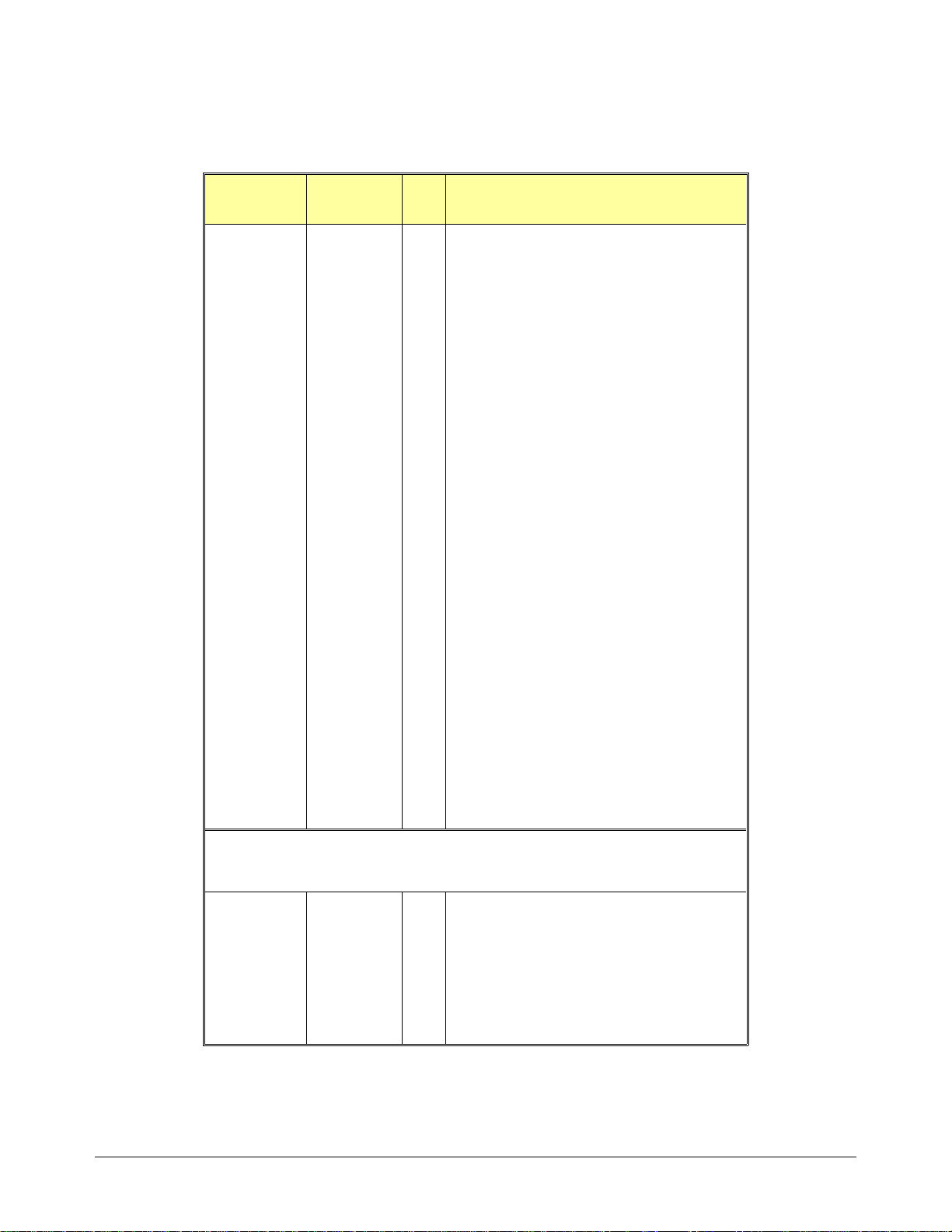
Table 3-1. Agilent E1463A Replaceable Parts (Continued)
Reference
Designator
R405-R406 0757-0346 RESISTOR 10 +-1% .125W TF TC=0+-100
RP101-RP103 1810-0279 3 NETWOR K- RES 10-SIP 4.7K OHM X 9
RP301- RP302 1810-0265 4 NETWORK-RES 16 -DIP 680. 0 OHM X 8
RP401- RP402 1810-0265 NETWORK-RES 16-DIP 680.0 OHM X 8
SP101 3101-2094 1 SWITCH-DIP ROCKER 8-1A 0.15A 30VDC
U101 1820-3631 2 IC COMPARATOR CMOS/HCT MAGNITUDE 8-BIT
U102 1820-3975 3 IC DRIVER CMOS/HC LINE OCTL
U103 1820-4586 1 IC DRIVER/RECEIVER CMOS/HCT BUS OCTL
U104-U105 1820-3975 IC DRIVER CMOS/HC LINE OCTL
U106 1820-3631 IC COMPARATOR CMOS/HCT MAGNITUDE 8-BIT
U107 1820-4147 1 IC LATCH CMOS/HCT TRANSPARENT OCTL
U108-U109 1820-3714 2 IC TRANSCEIVER TTL/ALS BUS OCTL
U110-U111 1820-3079 2 IC DECODER CMOS/HC BIN 3-TO-8-LINE
U112 1820-4643 2 IC GATE CMOS/HCT NOR QUAD 2-INP
U201 1820-4643 IC GATE CMOS/HCT NOR QUAD 2-INP
U203 1820-4242 1 IC SCHMITT-TRIG CMOS/HCT INV HEX
U204 1820-3081 2 IC FF CMOS/HC D-TYPE POS-EDGE-TRIG
U205 1820-4590 1 IC MV CMOS/HC MONOSTBL RETRIG DUAL
U206 1820-6731 1 IC-ASIC GATE-ARRAY CMOS
U207 1820-4057 1 IC BUFFER TTL/F NAND QUAD 2-INP
Agil e n t P ar t
Number
Qty Part Description
U208 1820-3097 1 IC GATE CMOS/HC AND QUAD 2-INP
U209 1820-3081 IC FF CMOS/HC D-TYPE POS-EDGE-TRIG
U301-U302 1820-4086 4 IC FF CMOS/HCT D-TYPE POS-EDGE-TRIG
U303-U304 1858-0069 4 TRANSISTOR ARRAY 18-PIN PLASTIC DIP
U401-U402 1820-4086 IC FF CMOS/HCT D-TYPE POS-EDGE-TRIG
U403-U404 1858-0069 TRANSISTOR ARRAY 18-PIN PLASTIC DIP
† NOTE: For modules with serial numbers prior to 3126A01817, the following
parts must be used for replacement (see inset in figure 3-1).
*A1 E1463-66201 1 GP RELAY ASSEMBLY
*MP1 E1400-84105 1 EXT HANDLE KIT-BOTTOM
*MP2 E1400-84106 1 EXT HANDLE KIT-TOP
*PNL1 E1463-00201 1 FRONT PANEL
*SCR1-*SCR2 0515-0368 2 SCREW-MACHINE ASSY M2.5 X 12MM-LG
*SCR9-*SCR10 0515-1375 3 SCREW-MACHINE M2.5 X 0.45 6MM-LG FLAT-HD
*SCR11-*SCR12 0515-1968 2 SCREW PH M2.5 X 11TX
PAN-HD
Chapter 3 Replaceable Parts 39

Figure 3-1. E1463A Mechanical Replaceable Parts
40 Replaceable Parts Chapter 3
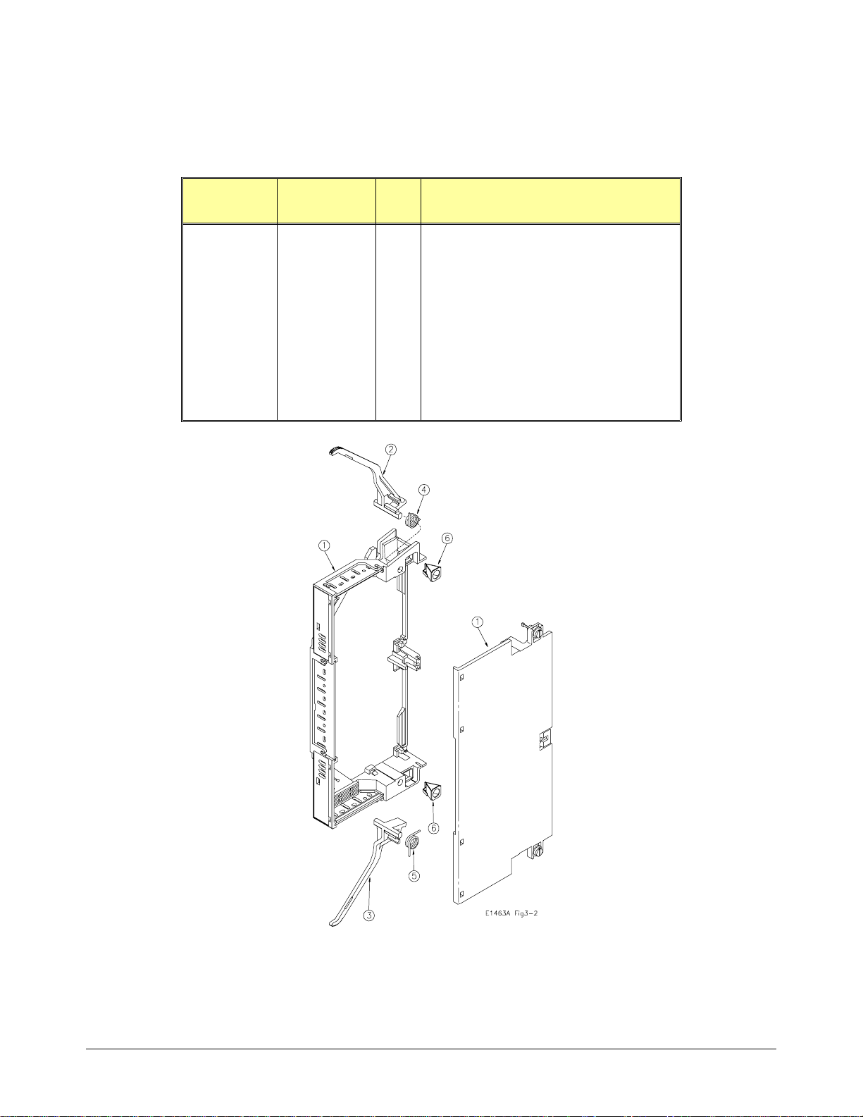
Table 3-2. Agilent E1463A Terminal Case Replaceable Parts
(for modules wit h serial numbers after 312 6A01818)
Reference
Designator
1 E1400-84405 1 Case Assembly - Terminal
2
3 E1400-45104 1 Bottom Lever
4
5 1460-2553 1 Torsion Spring - Right Hand Wound
6
PCA
Agil e n t P ar t
Number
E1400-45103
1460-2552
1390-1027
E1463-66510
1252-1574
0515-0905
E1400-21204
Qty Part Description
Top Leve r
1
Torsion Spring - Left Hand Wound
1
Receptical Quic k Fas tener
2
PC Assembly:
Screw Terminal (Standard)
1
Connector - Rcpt, 48 Pin (Option A3G)
2
Screw Pan Head 2.5 x 06 (Option A3G)
4
Crimp & Insert Connector Support (Option A3G)
4
Figure 3-2. E1463A Terminal Case Replaceable Parts
Chapter 3 Replaceable Parts 41

Table 3-3. Agilent E1463A Terminal Case Replaceable Parts
(for modules wit h serial numbers prior to 3126A01817)
Reference
Designator
A1 E1400-84401 1 TERMINAL MODULE CASE ASSY
MP1 03852-01201 1 CLAMP
MP2 03852-86701 1 PAD-CLAMP
MP3 0515-2109 1 SCREW-MACHINE 10-24 .625-IN-LG
MP4 1390-0846 2 FASTENER-CAPTIVE SCREW M2.5 X 0.45
MP5 E1300-01 20 2 1 CLAMP ST RA I N REL IE F
MP6 E1400- 44104 1 TERMINAL HOUSING-BOTTOM
MP7 E1400- 44105 1 TERMINAL HOUSING-TOP
Agilent Part
Number
Qty Part Description
(See Figure 3-1)
PAN-HD-SLT
Figure 3-3. E1463A Terminal Case Replaceable Parts
42 Replaceable Parts Chapter 3

Table 3-4. Agilent E1463A Terminal Module PCA Rep laceable Parts
Reference
Designator
A3 E1463-66510 1 TERMINAL MODULE PC ASSEMBLY
P1-P2 1252-1577 2 CONNECTOR-POST TYPE 5.08-PIN-SPCG
TB1-TB8 0360-2391 8 TERMINAL MODU LE 12 P. POLYAMIDE
Agilent Part
Number
Qty Part Description
(See Figure 3-3)
48-CONTACT
NOTE: For option A3G re placeable parts, see Table 3-2 .
Figure 3-4. E1463A Termin al Board
Chapter 3 Replaceable Parts 43

Table 3-5. Agilent E1463A Reference Designators
Reference Designators
A .................. assembly P.................. electrical connector (plug)
BRK... ........ .. bra c ket PCB ............ printed circu it board
C.................. capacitor PNL ............ panel
CR................ diode Q ...... ........ ...t ransis t o r
CS................case R .................resistor
CVR............. cover RP.......... ..... resistor pa c k
F................... fuse RT ...............thermistor probe
J............... .... electric al con n e c tor (ja c k ) SC R............ .screw
JM................ jumper SHD ............ shield
K ..................relay SW .............. switch
MNL.............manual TB ............... termina l b lock (mo d ule)
MP ...............mechanical part U ................. integrated circuit
44 Replaceable Parts Chapter 3

Introduction
Chapter 4
Service
This chapter contains service information for the Agilent E1463A
Form C Switch Mod ule , inc luding trouble shooting tech niques
and repair and maintenance guideli ne s.
WARNING
Repair Strategy
Equipment
Required
Do not perform any of the service procedures shown unless
you are a qualified, service-trained technic ian, and have read
the WARNINGS and CAUTIONS in Cha pter 1.
Agilent Technologies recommends component replacement for the
Agilent E1463A. Proc e dure s in this chapter describe troubleshoo ting
techniques. Schematics and Component Locators are located at the back of
this manual. Component- level replaceable parts lists are contained in
Chapter 3, "Replaceable Parts." See Chapter 1, "General Information," for a
description o f rela y life factors.
Equipment req uir e d f or the Agilent E1463A Form C S witch Module
troublesho oting and repair is l isted in Table 1-1 , "Re c ommended Test
Equipment. " Any equipment t ha t sa ti sf ie s the requirements given in the
table may be su bstituted.
To avoid damage to the screw head slots, use a T8 Tor x dr ive r to r e move
the front panel handles and a T10 To rx d rive r to r emove the shields.
Service Aids See Chapter 3, "Replaceable Parts," for descriptions and locations of
Agilent E1463A replaceable parts. Service notes, manual updates, and
service lite rat ur e for the swi tc h module may be available through Agilent
Technologies . For infor mation, contact your ne a rest Agil e nt Te c hnologies
Sales and Support Offi ce.
Chapter 4 Service 45

Troubleshooting
To troublesh oot a switch module problem you must f irst identify th e
problem and then isolate the cause of the problem to a replaceable part. See
Chapter 3, "Replaceable Parts," and the component locators at the back of
this manual for descriptions and locations of Agilent E1463A replaceable
parts.
Identifying the
Problem
Problem
Type Symptom
Self-test Errors Non-zero error code in response to
Operator Errors Non-zero error code in response to
Catastrophic
Failures
Performance Out
of Specification
Table 4-1 list s som e common problem s, along with symptom s and possible
solutions. If the problem persists, pe rform component-le ve l troubleshooting
using the compone nt locator and schematics.
Table 4-1. Agilent E1463A Common Problems
Possible
Solutions
See Table 4-4 for information on
the *TST? comman d.
the SYST:ERR? command.
Not responding to commands. Check logical address setting.
Failing Closed Channel R esist ance
Test (see Test 2-1 in Chapter 2).
Failing DC Isolation test (See Test
2-2 in Chapter 2)
self-test errors.
See Appendix C of the the Agilent
E1463A User’s Manual for Switch
Module errors and causes.
See Appendix B of the
Agilent E1405 User’s Manual for
additional information on ope rator
errors.
Check GPIB cables and connections.
See "Testing the Assembly" in this
chapter.
Check user wiring, test connections,
and installed protection devices.
Replace relays that corre spon d to the
channels that are failing (see Table
4-3).
If most of the channels are near or
above the test limit (2.0 Ohms),
replace entire printed circuit board
(Agilent part number E1463-66501)
Check user wiring, test connections,
and installed protection devices.
Remove dust from relay module and
terminal module printed circuit board.
46 Service Chapter 4

Testing the
Assembly
You can use the test s an d checks in Table 4-2 t o isolate the proble m. Se e
Figures 3-1, 3-2, and 3- 3 in Chapter 3 for locati ons of me c ha ni cal parts.
See the component locator included with this manual for locations of
electrical components.
Table 4-2. Agilent E1463A Tests/Checks
Test/Check Reference Designator Check:
Heat Damage - - - - - - - - - - Discolored PC boards
Damaged insulation
Evidence of arcing
Switch/Jumper
Settings
Switch Module
PCA
J101, J201
SP101
F601, F602
P1, P2, J1, J2
K0-K31
IRQ Level setting
LADDR setting
Fuse continuity
Connector contacts
Test 2-1, Closed Channel
Resistance Test
Checking for Heat Damage
Inspect the asse mbly for signs of a bnor m al internally generated heat su ch as
discolored pr inted circuit boa r ds or co mponents, dam ag ed insulation, or
evidence of arcing.
Checking Switches/Jumpers
Verify that the logical address swit c h is se t correctly (factor y se t a t 120).
Verify that the interrupt priority jumpers are set correctly (factory set at
level 1).
Checking the Switch Module PCA
Check the followi ng:
• Verify that fuses F601 and F602 are good.
• Check connectors J1, J2, P1, an d P2 for da ma ge .
• Perform Test 2-1 in Chapter 2.
Chapter 4 Service 47

Matching Relays to Channels
Use Table 4-3 to help match channel numbers to relay and drive circuit
reference designators.
Table 4-3. Channel Relays/Referen ce Designators
Channel Relay Driver Driver Register
00 K00
01 K01
02 K02
03 K03
04 K04
05 K05
06 K06
07 K07
08 K08
09 K09
10 K10
11 K11
12 K12
13 K13
14 K14
15 K15
16 K16
17 K17
18 K18
19 K19
20 K20
21 K21
22 K22
23 K23
24 K24
25 K25
26 K26
27 K27
28 K28
29 K29
30 K30
31 K31
U303 U301
U304 U302
U403 U401
U404 U402
48 Service Chapter 4

Self-Test
Error Codes
Table 4-4 shows the se lf - te st err or co de s fo r th e Swit c h Module. The
meaning of each code is given in the right-hand column. If a self-test failure
occurs, cycle power and repeat the test. If the problem reoccurs, the device
may need repair.
Table 4-4. Self-test E rror Codes
Error* Description
+0
+ss01
+ss02
+ss03
+ss10
+ss11
Self-test passes
Firmware er ro r
Bus error (communica tions problem with car d)
Bad ID information in ID register
Interrupt expected but not recei ved
Busy bit was not held ≈10.5 to 18.5 msec
*ss = card number (with leading zero deleted)
Disassembly Use the following procedures to disassemble the Agi le nt E1463A Switch
Module. For dis as sembly refer to Figure 4-1.
Switch Module
Disassembly 1. To remove the covers:
• Remove the nine T10 Tor x sc r e ws from the top cover as shown.
• Lift the to p co ve r off of the module.
• Turn the assembly over and lift off the bottom cover.
2. To remove the front panel:
• Remove the two T8 Tor x sc r ews from the fron t pa ne l ha ndles as
shown.
• Remove the T8 To rx screw holding the panel t o the A1 PC
Assembly as shown.
• Lift the front panel from the A1 assembly.
Chapter 4 Service 49

Figure 4-1. Agilent E1463A Disassembly
50 Service Chapter 4

Repair/Maintenance Guidelines
This sectio n provides guideli ne s fo r re pa iring and mainta ining the
Agilent E1463A S witch Module, including:
• ESD precautions
• S oldering printed circuit boards
• Po st-repair safety checks
ESD Precautions Electrostatic disc ha r ge (E SD) ma y da ma ge static-sensi tive devices in the
switch mod ule s. T his damage can range f ro m slight parame te r deg rada tion
to catastrophic failure. When handling the switch module assemblies, follow
these guideli ne s to avoid damaging components:
• Always use a static-free work stati on wi th a pa d of con ductive rubber or
similar ma te r ial whe n ha ndling electr oni c com ponents.
• Do not use pliers to remove a MOS or CMOS device from a hi gh-gr ip
socket. Instead, use a small sc rewdr i ve r to pr y the de vice up from one
end. Slowly lift the device up, one pair of pins at a time.
Sold e rin g Pr i n t ed
Circuit Boards
• After you remove a MOS or CMOS device from a module, place the
device onto a pad of conductive foam or ot he r suitable holdi ng ma t eri al .
• If a device requires soldering, be sur e the ass embly is placed on a pad of
conductiv e mat e ria l. Also, be sure that you, the pa d, an d the soldering
iron tip are grounded to the assembly.
The etched circu it boards in the switch module have pla ted- through holes
that allow a solder path to bo th si de s of the insulating ma te r ial. Soldering
can be done from eit he r side of the boa rd with equally goo d results. When
soldering to an y ci rcu it board, keep in mind the following guidelines:
• The relays used on these printed circuit boards require special soldering
techniques and e quipment. The use of a sol de r-p ot is recommended for
relay removal and replacement.
• Do not use a high power soldering iron on e tc he d cir c uit boa r ds, as
excessive heat m ay lift a conductor or damage the boa r d.
• Use a suc t ion de vice or wooden t oothpick to re move so lder from
component mounting holes. Wh en using a suction de vic e , be su re the
equipment is pr operly grounded.
Chapter 4 Service 51

Post-Repair
Safety Checks
After making repa irs to the module, inspect the devi c e for an y signs of
abnormal int erna lly generated he a t, suc h a s dis colored printed c ir c uit boa r ds
or components, dama ge d insulation, or evi de nc e of arci ng. De te r mi ne and
correct the cause of the condition. Then pe r fo rm the Functional Verific a ti o n
Test described in Chapter 2 to verify that the device is functional.
Component Locators and Schematic Diagrams
Table 4-5 list s Com ponent Locator Di ag ram s an d Sche ma t ic Dia gr a ms f or
the Agilent E1463A Switch Module.
Table 4-5. Compone nt Lo cat ors and Schematics Diag rams
Part Number Drawing Number Drawing Title
Component
Locator
Diagram
Schematic
Diagrams
E1463-66501 L-E1463-66501 E1463A Form C Switch Component Assembly
E1463-66501
E1463-66501
E1463-66501
E1463-66501
E1463-66501
S-E1463-66501 (1 of 5)
S-E1463-66501 (2 of 5)
S-E1463-66501 (3 of 5)
S-E1463-66501 (4 of 5)
S-E1463-66501 (5 of 5)
E1463A Form C Switch - VXI Interface #1
E1463A Form C Switch - VXI Interface #2
E1463A Form C Switch - Relay Drive rs/R el ays 0-15
E1463A Form C Switch - Relay Drive rs/R el ays 16 -31
E1463A Form C Switch - VXI P1 and P2 Conn
52 Service Chapter 4
 Loading...