

Page 1
General
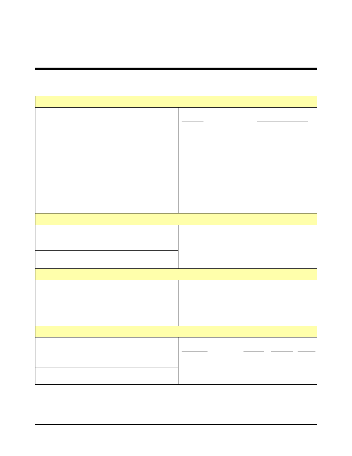
Appendix A
Form C Switch Specifications
Module Size / Device Type:
C-size VXIbus, Register based, A16/D16, Interrupter
(levels 1-7, jumper selectable
Power Requirements:
Voltage: +5 V
Peak Module Current (A) 0.10 0.60**
Dynamic Module Current (A) 0.10 0.01
Watts/slot: 10 W
Cooling/slot: 0.08 mm H
Operating Temperature: 0° - 55°C
Operating Humidity: 65% RH, 0° - 40°C
Terminals:
Screw type, maximum wire size 16 AWG
0 @ 0.42 Liter/sec for 10oC rise
2
+12 V
Input Characteristics
Maximum Input Voltage:
220 Vdc or 250 Vac
220 Vdc or 250 Vac
Maximum Current per Channel (non-inductive):
5 Adc or ac
rms
Terminal to Terminal
rms
Terminal to Chassis
rms
DC Performance
Relay Life (Typical):*
Condition
No Load 5 x 10
250 Vac, 2A, Resistive 10
250 Vac, 5A, Resistive 10
250 Vac, 2A, p.f. = 0.4 10
250 Vac, 5A, p.f. = 0.4 10
30 Vdc, 1A, Resistive >10
30 Vdc, 5A, Resistive 10
30 Vdc, 1A, L/R = 7 msec >10
30 Vdc, 5A, L/R = 7 msec 10
Maximum Switchable Power per Channel:
150 W dc; 1250 VA per switch
1500 W dc; 12,500 VA per module
Number of Operations
6
5
6
5
6
5
6
5
7
Insulation Resistance (between any two points):
6
>5x10
W at 40°C, 95% RH
8
>5x10
W at 25°C, 40% RH
Maximum Thermal Offset per Channel:
<7
mV (<3 mV typical)
Closed Channel Resistance:
>100 mA: <0.250 W (<2 W at end of relay life)
<100 mA: <20
AC Performance
Capacitance:
<30 pF (Channel to Channel)
<40 pF (Channel to Common)
<25 pF (Common to Guard)
Bandwidth (-3 dB):
>10 MHz (typical)
* Relays are subject to normal wearout based on the number of operations.
** Absolute worst case when all relays are closed simultaneously.
Crosstalk (db) (for Z1 = Zs =50 W):
Frequency
Channel to Channel <-83 <-63 <-43
Common to NO or NC <-80 <-60 <-40
Module to Module <-100 <-100 <-90
Form C Switch Specifications 77Appendix A
W
<10 kHz <100 kHz <1 MHz
 Loading...