

Page 1

Contents
HP E1460A Relay Multiplexer User’s Manual
Warranty . . . . . . . . . . . . . . . . . . . . . . . . . . . . . . . . . . . . . . . . . . 5
WARNINGS . . . . . . . . . . . . . . . . . . . . . . . . . . . . . . . . . . . . . . . . 6
Safety Symbols . . . . . . . . . . . . . . . . . . . . . . . . . . . . . . . . . . . . . . 6
Declarati on of Conformity . . . . . . . . . . . . . . . . . . . . . . . . . . . . . . . . . 7
Reader Comment Sheet . . . . . . . . . . . . . . . . . . . . . . . . . . . . . . . . . . 9
Chapter 1. Getting Started wi th the HP E1460A M ultiplexer . . . . . . . . . . . . . . . . 11
Using This Chapter . . . . . . . . . . . . . . . . . . . . . . . . . . . . . . . . . . . . 11
Multiplexer Description . . . . . . . . . . . . . . . . . . . . . . . . . . . . . . . . . . 11
Channel Re la y Switches . . . . . . . . . . . . . . . . . . . . . . . . . . . . . . . 12
Control Relays . . . . . . . . . . . . . . . . . . . . . . . . . . . . . . . . . . . . 14
Basic Operating Modes . . . . . . . . . . . . . . . . . . . . . . . . . . . . . . . . 15
Typical C onfiguratio n s . . . . . . . . . . . . . . . . . . . . . . . . . . . . . . . . 15
Warnings and Cautions . . . . . . . . . . . . . . . . . . . . . . . . . . . . . . . . . . 16
WARNING . . . . . . . . . . . . . . . . . . . . . . . . . . . . . . . . . . . . . . 16
CAUTION . . . . . . . . . . . . . . . . . . . . . . . . . . . . . . . . . . . . . . 16
Configuring the Multiplexer . . . . . . . . . . . . . . . . . . . . . . . . . . . . . . . . 16
Setting the Logical Address Switch . . . . . . . . . . . . . . . . . . . . . . . . . 17
Setting the Status Register Switch . . . . . . . . . . . . . . . . . . . . . . . . . . 18
Setting the Interrupt Priority . . . . . . . . . . . . . . . . . . . . . . . . . . . . . 19
Configuring the Switch Card Wire Jumpers . . . . . . . . . . . . . . . . . . . . . . . 20
Connecting the Analog Bus . . . . . . . . . . . . . . . . . . . . . . . . . . . . . . . . 22
Installing the Multiple xer in a Mainf rame . . . . . . . . . . . . . . . . . . . . . . . . . 23
Available Terminal Modules . . . . . . . . . . . . . . . . . . . . . . . . . . . . . . . 24
Screw-type Terminal Modul e . . . . . . . . . . . . . . . . . . . . . . . . . . . . . 24
Terminal Module Option A3E . . . . . . . . . . . . . . . . . . . . . . . . . . . . 25
Connecting User Inputs . . . . . . . . . . . . . . . . . . . . . . . . . . . . . . . . . . 27
Attach ing a Termina l Mo dule to the Multiplexe r . . . . . . . . . . . . . . . . . . . . . 28
Wiring a Terminal Modu le . . . . . . . . . . . . . . . . . . . . . . . . . . . . . . . . 29
Programming th e Mul ti pl ex er . . . . . . . . . . . . . . . . . . . . . . . . . . . . . . . 31
Specifying SCPI Commands . . . . . . . . . . . . . . . . . . . . . . . . . . . . . 31
Multiplexer Ch an ne l Addr esses . . . . . . . . . . . . . . . . . . . . . . . . . . . 31
Multiplexer Card Numbers . . . . . . . . . . . . . . . . . . . . . . . . . . . . . . 31
Low or High Terminal . . . . . . . . . . . . . . . . . . . . . . . . . . . . . . . . 33
Bank Number . . . . . . . . . . . . . . . . . . . . . . . . . . . . . . . . . . . . . 33
Channel Number . . . . . . . . . . . . . . . . . . . . . . . . . . . . . . . . . . . 33
SCPI Command Format Used in Th is Manual . . . . . . . . . . . . . . . . . . . . 34
Initial Operation . . . . . . . . . . . . . . . . . . . . . . . . . . . . . . . . . . . . . . 35
Chapter 2. Using the HP E1460A Multiplexer . . . . . . . . . . . . . . . . . . . . . . . . 37
Using This Chapter . . . . . . . . . . . . . . . . . . . . . . . . . . . . . . . . . . . . 37
Multiplexer Commands . . . . . . . . . . . . . . . . . . . . . . . . . . . . . . . . . . 37
Reset Conditions . . . . . . . . . . . . . . . . . . . . . . . . . . . . . . . . . . . . . . 38
HP E1460A Relay Multiplexer User’s Manual Contents 1
Page 2

Switchin g Channels . . . . . . . . . . . . . . . . . . . . . . . . . . . . . . . . . . . . 38
Scanning Channels . . . . . . . . . . . . . . . . . . . . . . . . . . . . . . . . . . . . . 44
Measure me nt and Test Configurat ions . . . . . . . . . . . . . . . . . . . . . . . . . . 55
Connecting the Analog Bus . . . . . . . . . . . . . . . . . . . . . . . . . . . . . . 55
Recalling and Saving States . . . . . . . . . . . . . . . . . . . . . . . . . . . . . . . . 60
Storing States . . . . . . . . . . . . . . . . . . . . . . . . . . . . . . . . . . . . . 60
Recalling States . . . . . . . . . . . . . . . . . . . . . . . . . . . . . . . . . . . . 60
Detecti ng E rror Conditions . . . . . . . . . . . . . . . . . . . . . . . . . . . . . . . . 60
Synchroni zi ng the Multiple xe r . . . . . . . . . . . . . . . . . . . . . . . . . . . . . . 62
Synchroni zi ng Instruments . . . . . . . . . . . . . . . . . . . . . . . . . . . . . . 62
Querying the Multiplexer . . . . . . . . . . . . . . . . . . . . . . . . . . . . . . . . . 63
Chapter 3. HP E1460A Multiplex er Com mand Re fer enc e . . . . . . . . . . . . . . . . . . 65
Using This Chapter . . . . . . . . . . . . . . . . . . . . . . . . . . . . . . . . . . . . 65
Command Types . . . . . . . . . . . . . . . . . . . . . . . . . . . . . . . . . . . . . . 65
Common Command Format . . . . . . . . . . . . . . . . . . . . . . . . . . . . . 65
SCPI Command For ma t . . . . . . . . . . . . . . . . . . . . . . . . . . . . . . . 65
Linking Commands . . . . . . . . . . . . . . . . . . . . . . . . . . . . . . . . . . 67
SCPI Command Re fe re nc e . . . . . . . . . . . . . . . . . . . . . . . . . . . . . . . . 68
ABORt . . . . . . . . . . . . . . . . . . . . . . . . . . . . . . . . . . . . . . . . . . . 68
ARM . . . . . . . . . . . . . . . . . . . . . . . . . . . . . . . . . . . . . . . . . . . . 69
:COUNt . . . . . . . . . . . . . . . . . . . . . . . . . . . . . . . . . . . . . . . . 69
:COUNt? . . . . . . . . . . . . . . . . . . . . . . . . . . . . . . . . . . . . . . . 70
INITiate . . . . . . . . . . . . . . . . . . . . . . . . . . . . . . . . . . . . . . . . . . 71
:CONTinuou s . . . . . . . . . . . . . . . . . . . . . . . . . . . . . . . . . . . . . 71
:CONTinuous? . . . . . . . . . . . . . . . . . . . . . . . . . . . . . . . . . . . . 72
[:IMMediate] . . . . . . . . . . . . . . . . . . . . . . . . . . . . . . . . . . . . . 72
OUTPut . . . . . . . . . . . . . . . . . . . . . . . . . . . . . . . . . . . . . . . . . . 73
:ECLTrgn[:STATe] . . . . . . . . . . . . . . . . . . . . . . . . . . . . . . . . . . 73
:ECLTrgn[:STATe]? . . . . . . . . . . . . . . . . . . . . . . . . . . . . . . . . . 74
[:EXTernal][:STATe] . . . . . . . . . . . . . . . . . . . . . . . . . . . . . . . . . 74
[:EXTernal][:STATe]? . . . . . . . . . . . . . . . . . . . . . . . . . . . . . . . . 75
:TTLTrgn[:STATe ] . . . . . . . . . . . . . . . . . . . . . . . . . . . . . . . . . . 75
:TTLTrgn[:STATe ]? . . . . . . . . . . . . . . . . . . . . . . . . . . . . . . . . . 76
[ROUTe:] . . . . . . . . . . . . . . . . . . . . . . . . . . . . . . . . . . . . . . . . . 77
CLOSe . . . . . . . . . . . . . . . . . . . . . . . . . . . . . . . . . . . . . . . . 77
CLOSe? . . . . . . . . . . . . . . . . . . . . . . . . . . . . . . . . . . . . . . . . 79
FUNCtion . . . . . . . . . . . . . . . . . . . . . . . . . . . . . . . . . . . . . . . 79
FUNCtion? . . . . . . . . . . . . . . . . . . . . . . . . . . . . . . . . . . . . . . 81
OPEN . . . . . . . . . . . . . . . . . . . . . . . . . . . . . . . . . . . . . . . . . 81
OPEN? . . . . . . . . . . . . . . . . . . . . . . . . . . . . . . . . . . . . . . . . 83
SCAN . . . . . . . . . . . . . . . . . . . . . . . . . . . . . . . . . . . . . . . . . 84
SCAN:MODE . . . . . . . . . . . . . . . . . . . . . . . . . . . . . . . . . . . . . 85
SCAN:MODE? . . . . . . . . . . . . . . . . . . . . . . . . . . . . . . . . . . . . 86
SCAN:PORT . . . . . . . . . . . . . . . . . . . . . . . . . . . . . . . . . . . . . 87
SCAN:PORT? . . . . . . . . . . . . . . . . . . . . . . . . . . . . . . . . . . . . 87
STATus . . . . . . . . . . . . . . . . . . . . . . . . . . . . . . . . . . . . . . . . . . 88
:OPERation :CONDi tion? . . . . . . . . . . . . . . . . . . . . . . . . . . . . . . 90
2 HP E1460A Relay Multiplexer User’s Manual Contents
Page 3

:OPERation:E NABle . . . . . . . . . . . . . . . . . . . . . . . . . . . . . . . . . 90
:OPERation:E NABle? . . . . . . . . . . . . . . . . . . . . . . . . . . . . . . . . 90
:OPERation[:EVENt] ? . . . . . . . . . . . . . . . . . . . . . . . . . . . . . . . . 90
:PRESet . . . . . . . . . . . . . . . . . . . . . . . . . . . . . . . . . . . . . . . . 91
SYSTem . . . . . . . . . . . . . . . . . . . . . . . . . . . . . . . . . . . . . . . . . . 92
:CDEScription? . . . . . . . . . . . . . . . . . . . . . . . . . . . . . . . . . . . . 92
:CPON . . . . . . . . . . . . . . . . . . . . . . . . . . . . . . . . . . . . . . . . 92
:CTYPe? . . . . . . . . . . . . . . . . . . . . . . . . . . . . . . . . . . . . . . . 93
:ERRor? . . . . . . . . . . . . . . . . . . . . . . . . . . . . . . . . . . . . . . . . 93
TRIGger . . . . . . . . . . . . . . . . . . . . . . . . . . . . . . . . . . . . . . . . . . 94
[:IMMediate] . . . . . . . . . . . . . . . . . . . . . . . . . . . . . . . . . . . . . 94
:SLOPe . . . . . . . . . . . . . . . . . . . . . . . . . . . . . . . . . . . . . . . . 95
:SLOPe? . . . . . . . . . . . . . . . . . . . . . . . . . . . . . . . . . . . . . . . . 95
:SOURce . . . . . . . . . . . . . . . . . . . . . . . . . . . . . . . . . . . . . . . 95
:SOURce? . . . . . . . . . . . . . . . . . . . . . . . . . . . . . . . . . . . . . . . 97
IEEE 488.2 Common Command Reference . . . . . . . . . . . . . . . . . . . . . . . . 98
SCPI Command Quick Refere nc e . . . . . . . . . . . . . . . . . . . . . . . . . . . . . 99
Appendix A. HP E1460A Specificati ons . . . . . . . . . . . . . . . . . . . . . . . . . . . . 101
Relay Life . . . . . . . . . . . . . . . . . . . . . . . . . . . . . . . . . . . . . . . . . 102
Appendix B. Register-Based Pro gr amming . . . . . . . . . . . . . . . . . . . . . . . . . . 103
About This App en dix . . . . . . . . . . . . . . . . . . . . . . . . . . . . . . . . . . . 103
Register Addressing . . . . . . . . . . . . . . . . . . . . . . . . . . . . . . . . . . . . 103
The Base Address . . . . . . . . . . . . . . . . . . . . . . . . . . . . . . . . . . . 104
Register Offset . . . . . . . . . . . . . . . . . . . . . . . . . . . . . . . . . . . . 105
Register Descriptions . . . . . . . . . . . . . . . . . . . . . . . . . . . . . . . . . . . 106
The WRITE Registers . . . . . . . . . . . . . . . . . . . . . . . . . . . . . . . . 106
The READ Re gisters . . . . . . . . . . . . . . . . . . . . . . . . . . . . . . . . . 106
Status/C ontrol Register . . . . . . . . . . . . . . . . . . . . . . . . . . . . . . . . 107
ID and Device Type Registers . . . . . . . . . . . . . . . . . . . . . . . . . . . . 108
Relay Control Registers . . . . . . . . . . . . . . . . . . . . . . . . . . . . . . . . 108
Program Timing and E xe cu ti on . . . . . . . . . . . . . . . . . . . . . . . . . . . . . . 110
Using a Multimete r wit h the Multiplexer . . . . . . . . . . . . . . . . . . . . . . . 111
Programming Exa mp les . . . . . . . . . . . . . . . . . . . . . . . . . . . . . . . . . . 112
System Configura ti on . . . . . . . . . . . . . . . . . . . . . . . . . . . . . . . . . 112
Closing/Op en ing a Channel . . . . . . . . . . . . . . . . . . . . . . . . . . . . . 113
Reading the ID,
Devic e Type ,
and Stat us Registers . . . . . . . . . . . . . . . . . . . . . . . . . . . . . . . . . 114
Scanning Channels . . . . . . . . . . . . . . . . . . . . . . . . . . . . . . . . . . 115
Appendix C. Multiplexer Error Message s . . . . . . . . . . . . . . . . . . . . . . . . . . . 119
HP E1460A Relay Multiplexer User’s Manual Contents 3
Page 4

Notes
4 HP E1460A Relay Multiplexer User’s Manual Contents
Page 5

Certification
Hewlett- Packard Company certifies that this product met i ts published s pecifications at the tim e of shipment fr om the factory. HewlettPackard further certifies that its calibration measurements are traceable to the United States National Institute of Standards and Te ch nol ogy (formerly National Bureau of Standards), to the extent allowed by that organization’s calibration facility, and to the calibration
facilities of other International Standards Organization members.
Warranty
This Hewlett-Packard product is warranted against defects in materials and workmanship for a period of three years from date of shipment. Duratio n and conditi ons of warr ant y for thi s produ ct m ay be sup erse ded when t he product is int egrat e d into (becom e s a part of)
other HP produc ts. During the warran ty perio d, Hewl ett -Pa ck ar d Com pa ny will , at its optio n, either repai r or repl ac e produc t s whi ch
prove to be defective.
For warrant y servic e or repai r, thi s produc t must be retur ned to a service faci lity de sign at ed by Hewlet t-P ac kard (HP ). Buyer sha l l prepay shipping cha rges to HP and HP shall pay shipping c harge s to retu rn the product to Buyer. However, Buye r shall pay all shi ppi n g
charges , dut ies, and ta xe s for produc t s ret urn ed to HP fr om an ot her count ry.
HP warrants that its software and firmware designated by HP for use with a product will execute its programming instructions when
properly insta lle d on that produc t. HP does not wa rrant that the oper ati on of the pro duc t, or softwa re , or firm war e will be uninterrupted
or er ror free .
Limitation Of Warranty
The foregoing war ra nty sh all not apply to de fect s resul ting from imprope r or inadequate maint e nan ce by Buyer, Buye r-sup pl ied pr oducts or int`erfacing, unauthorized modification or misuse, operation outside of the environmental specifications for the product, or improper site pr ep ar at ion or ma int ena nce.
The design and imple men ta tio n of any circui t on this produc t is the sole respon sibi l ity of the Buyer. HP does not war rant the Buye r’s
circuitry or malf unc tion s of HP products that result from the Buyer’ s circui try . In addition, HP does not warra nt any dama ge tha t occurs as a result of the Buyer’s circ ui t or any defects that re sul t fr om Buyer-supplied pr oducts.
NO OTHER WARRANTY IS EXPRESSED OR IMPLIE D. HP SPECIFICALLY DI SCLAI MS THE IMPLI ED W ARRANTIE S OF
MERCHANTABILITY AND FITNESS FOR A PARTICULAR PURPOSE.
Exclusive Remedie s
THE REMEDIES PROVIDED HEREIN ARE BUYER’S SOLE AND EXCLUSIVE REM EDI ES. HP SHALL NOT BE LIABLE
FOR ANY DIRECT, INDIRECT, SPECIAL, INCIDENTAL, OR CONSEQUENTIAL DAMAGES, WHETHER BASED ON CONTRACT, TORT, OR ANY OTHER LEGAL THEORY.
Notice
The inform at i on c ont ained in this doc ument is subjec t to chan ge wi t hout noti ce . HEWLETT-PA CKARD (HP) MAKES NO WARRANTY OF ANY KIND WITH REGARD TO THIS MATERIAL, INCLUDING, BUT NOT LIM ITE D TO, THE IMPLI ED WARRANTIES OF MERCHANTABILITY AND FITNES S FOR A PARTICULAR PURPOSE. HP shall not be liable for errors contained
herein or for inci de nt al or consequentia l dam ag es in conne cti on wi th th e furni s hing, per fo rma nce or use of this mater i al . This doc ument contains proprietary information which is protected by copyright. All rights are reserved. No part of this document may be photocopied, repr oduc ed , or transl ate d to anothe r lan gua ge wi thout t he prior wr itten cons en t of Hewlet t-P ac kar d Compa ny. HP assume s no
respons ibilit y for th e us e or reli ab il i t y of i t s soft w ar e on equi pment th at is not fur ni sh ed b y HP .
Restricted Rights Legen d
Use, duplication or disclosure by the U.S. Government is subject to restrictions as set forth in subparagraph (c)(1)(ii) of the Rights in
Technical Data and Comp uter Softwa re clause in DFARS 252. 227- 701 3.
Hewlett-Pac kard Com pa ny
3000 Hanover Street
Palo Alto, California 94304 U.S.A.
Rights for non-DOD U.S. Governme nt Departm ent s and Agencies are as set forth in FAR 52.227-19 (c) (1,2).
HP E1460A 64-Channel Relay Multiplexer User’s Manual
Copyrigh t © 1995 He wlett-Pa cka rd Com pan y. All Rig hts Res er ve d.
Edition 5
HP E1460A 64-Channel Relay Multiplexer User’s Manual 5
Page 6

Documentatio n History
All Editions and Updates of this manual and their creation date are listed below. The first Edition of the manual is Edition 1. The Edition number increm ents by 1 whenever the manua l is revised . Updates, whic h are issued betwee n Edit ions , contain repl a cem ent pa ges
to correct or add additional information to the current Edition of the manual. Whenever a new Edition is created, it will contain all of
the Update inf orma t io n for the previ ou s Edi ti on. Each new Ed iti on or Upda te also incl ude s a revis ed c opy of this doc um en tat io n hi story page.
Edition 1 . . . . . . . . . . . . . . . . . . . . . . . . . . . . . . . . . . . . . . . . . . . . . January 1990
Edition 2 . . . . . . . . . . . . . . . . . . . . . . . . . . . . . . . . . . . . . . . . . . . . . . . . July 1992
Edition 3 . . . . . . . . . . . . . . . . . . . . . . . . . . . . . . . . . . . . . . . . . . . . . . August 1993
Edition 4 . . . . . . . . . . . . . . . . . . . . . . . . . . . . . . . . . . . . . . . . . . . . . October 1994
Edition 5 . . . . . . . . . . . . . . . . . . . . . . . . . . . . . . . . . . . . . . . . . . . November 1995
Safety Symbols
Instruction m a nual sy m bol affixed to product. Indicates that the user must refer to the
manual for specific WARNING or CAUTION information to avoid personal injury
or dama ge t o t he pr o du ct .
Indicates the field wiring terminal that must
be connec ted t o eart h groun d bef or e opera t ing the equipment—protects against electrical sho ck in ca se of fault .
Fram e or cha ss is gro und t er m i nal — ty pi -
or
cally connects to the equipment’s metal
frame.
WARNING
CAUTION
Alternating curre nt (AC) .
Direct curr en t (DC).
Indicates hazardous voltages.
Calls at te nt i on t o a pr oce dure, practice, or
condit ion t hat co ul d ca use bodi l y inj ury or
death.
Calls at te nt i on t o a pr oce dur e, pr ac ti c e, or c on dition t hat co ul d pos sibl y ca us e da m age to
equipment or permanent loss of data.
WARNINGS
The following ge ner al safet y prec aut io ns mus t be obse rv ed du ring al l phas es of operati on , servi ce , and repai r of this prod uct .
Failure to compl y with thes e pr ecaut i ons or with spec i fic warni ngs elsewhe re in this manua l violat es safety stand ard s of desig n,
manufactur e, and inten ded use of the produc t. Hewl ett- Pac kar d Com pan y assum es no lia bi lit y for the custo mer’ s fai lure to
comply with these requirements.
Ground the e qui pm en t: For Saf ety Clas s 1 equipm ent (equ ip m ent havi ng a pr ot ectiv e ea rt h t er m i nal ) , a n uni nterru pt ible sa fe ty earth
ground must be provide d from the ma in s power sour ce to the prod uct input wi ring ter m inal s or suppli ed power cable .
DO NOT operat e the pr oduc t in an expl os ive atmo sph er e or in the pres en ce of flammabl e gase s or fume s.
For continued protection against fire, replace the line fuse(s) only with fuse(s) of the same voltage and current rating and type.
DO NOT use repaired fuses or short-circuited fuse holders.
Keep away from live circuits: Operati ng pers onne l must not re move equi pm e nt cover s or shiel ds . Proc ed ure s invo lv in g the rem ova l
of covers or shi el ds are for use by se rv ic e- t ra ined personnel onl y. Under certain cond it i ons , dangerous voltages may exist ev en wi t h the
equipment switc hed off. To avoid dange rous e lectr ical shock , DO NOT perform proc edu res involvi ng cover or shield removal unless
you are qualified to do so.
DO NOT operate damaged equipment: Whenever it i s possi bl e that the sa fe ty prot e ct ion fe at ur es buil t int o thi s product have been i mpaired, eithe r through phys ical da m age , exces sive mois ture , or any other reas on, REMOVE POW E R and do not use the produc t unt il
safe operation can be verifie d by serv ice-t ra ined pers onn el. If necessary, return the produ ct to a Hewlett -Pac kar d Sales a nd Se rvice Office for service and repair to ensure that safety features are maintained.
DO NOT service or adjust alone: Do not attempt internal service or adjustment unless another person, capable of rendering first aid
and resus ci t at i on, is pr esent.
DO NOT substitute parts or modify equipment: Becaus e of the da nge r of introduc i ng ad diti on al haz ar ds , do not inst all subs titut e
parts or perform any unaut hor ized modi ficat io n to the produc t. Retur n the produ ct to a Hewlet t-P ac kard Sa les and Se rvic e Offi ce for
service and repair to ensure that safety features are maintained.
6 HP E1460A 64-Channel Relay Multiplexer User’s Manual
Page 7

Declaration of Conformity
according to ISO/IEC Guide 22 and EN 45014
Manufacture r ’s Name : Hewlett-Pa ck ard Com pa ny
Lovela nd M a nufacturing Cent er
Manufacture r’s Addre s s: 815 14th Stre et S.W .
Loveland, Colorado 80537
declares, that the produc t:
Product Name: 64-Channe l Rel ay Mult ipl exe r
Model Number: E1460A
Product Options: All
conforms to the followi ng Produc t Spe cific ati ons:
Safety: IEC 1010-1 (1990) Incl . Amend 1 (1992) /E N610 10-1 (1993)
CSA C22.2 #1010.1 (1 992)
UL 1244
EMC: CISPR 11:1990/ EN5 5011 (1991 ): Group1 Cl a ss A
IEC 801-2:1991/ E N5008 2-1 (1 992) : 4kVCD, 8k VA D
IEC 801-3:1984/ E N5008 2-1 (1 992) : 3 V/m
IEC 801-4:1988/ E N5008 2-1 (1 992) : 1kV Power Lin e
Supplementar y Informa tio n: The pr oduc t her ewi th compl ie s wit h th e requ ire m e nts of the Low Volt ag e Di re ctive
73/23/E EC and the EMC Direc ti ve 89/3 36/ EE C (inclusive 93/68/EEC) an d carr ie s the "CE " mark ac cordingly.
Tested in a typic al confi gur at ion in an HP C-Size VXI mainfr am e .
August 20, 1995 Jim White, QA Manager
European c ont act : You r loca l He wle tt-Packard Sa le s and Service Offi ce or Hewl ett- Pac ka rd GmbH, De pa rtm ent
HQ-TRE, Herren be rge r Straß e 130, D-71034 Böbl in gen, Germa ny (FAX +49- 7031 -14- 3143 ).
HP E1460A 64-Channel Relay Multiplexer User’s Manual 7
Page 8

Notes
8 HP E1460A 64-Channel Relay Multiplexer User’s Manual
Page 9

Please fold and t ap e for mailing
Reader Comment Shee t
HP E1460A 64-Channel Relay Multiplexer User’s Manual
Edition 5
You can help us improve our manual s by sharin g your comm e nts and s ug ge sti ons. In appreciat ion of your tim e, we will
enter you in a quarterly drawing for a Hewlett -Pac kar d Palmtop Per sonal Computer (U.S. gove rnment employees
cann ot part icipate in the drawing).
Your Name
Company Name
Job Title
Address
City, State/Province
Country
Zip/Postal Code
Telephone Number with Area Code
Please list the system controller, ope rating system, pro gra m ming language, and plug -in modules you are usi ng.
fold here
BUSIN ES S R EP LY MAIL
FIRST CLASS PERMIT NO. 37 LOVELAND, CO
HEWLETT-PACKARD COMPANY
cut along this line
Measurement Systems Division
Learning Products Department
P.O. Box 301
Loveland, C O 80539-9984
NO POSTAGE
NECESSARY
IF MAILED
IN THE
UNITED STATES
fold here
Please pen cil- in on e cir cl e for eac h st ate me nt below: Disagree Agree
• The documentation is well organized. OOOOO
•Instructions are easy to understand. OOOOO
•The documentation is clearly written. OOOOO
•Examples are clear and useful. OOOOO
•Illustrati ons are cle ar and helpfu l. OOOOO
•The documentation meets my overall expectations. OOOOO
Please write any com m ents or sugge sti ons be lo w--be spec ific .
Page 10

10 HP E1460A 64-Channel Relay Multiplexer User’s Manual
Page 11

Getting Started with the HP E1460A
Using This Chapter
This chapter describes the multiplexer module, shows how to connect
external wiring, and contains informati on on how to program it using SCPI
(Standard Commands for Program mabl e Instrument s) co mman ds. This
chapter contains the following sections :
Chapter 1
Multiplexer
• Multiplexer Description. . . . . . . . . . . . . . . . . . . . . . . . . . . . . Page 11
• Warnings and Caution s . . . . . . . . . . . . . . . . . . . . . . . . . . . . . Page 16
• Configuring the Multiplexer . . . . . . . . . . . . . . . . . . . . . . . . . Page 16
• Configuring the Switch Card Wire Jump ers . . . . . . . . . . . . . Page 20
• Connecting the Analog Bus. . . . . . . . . . . . . . . . . . . . . . . . . . Page 22
• Installing the Multiplexer in a Mainframe. . . . . . . . . . . . . . . Page 23
• Available Terminal Modules. . . . . . . . . . . . . . . . . . . . . . . . . Page 24
• Connecting User Inputs . . . . . . . . . . . . . . . . . . . . . . . . . . . . . Page 27
• Attaching a Terminal Mod ule to the Mul tiplexer . . . . . . . . . Page 28
• Wiring a Terminal Module . . . . . . . . . . . . . . . . . . . . . . . . . . Page 29
• Programming the Multiplexer . . . . . . . . . . . . . . . . . . . . . . . . Page 31
• Initial Operation. . . . . . . . . . . . . . . . . . . . . . . . . . . . . . . . . . . Page 35
Multiplexer Description
The HP E1460A is a VXIbus C-Size register-based product whi ch provid es
switching (multi pl exing ) of up to 64 two-wire channels. Switching consis ts
of connecting a channel’s HI and/or LO line to COM in that bank. The
multiplexer can operate in a C-Size VXIbus mainframe using an
HP command module (for example, HP E1406A).
The 64-Channel Relay Multiplexer Modul e is c ompr ised of a rela y switc h card
(HP part number E1460-66502) and a standard screw-type terminal module
(HP part number E1460-80011). The HP E1460A is also available with
Option A3E that provides a c rimp-and-insert terminal housing and connectors.
If the crimp-and-insert terminal module without the HP E1460A r elay swit ch
card is desired, order HP part number E1460-80012. S ee page 25 for
information about the crimp-and-insert option.
The various configuration s are obtained by prog rammi ng (closi ng) c ertain
switch card relays, and/or sel ectio n of wir e jumpers on both the relay switch
card and terminal module.
Chapter 1 Getting Started with the HP E1460A Multip lexer 11
Page 12

The HP E1460A is used whe n high switch densities such as wire harness/
cable testing, semiconduct or testing, and/or printed-circuit board testing is
required. Primarily a dual 32-channel two-wire multiplexer, it can be easily
configured to perform one-wire, two-wire, three-wire, and four-wire functions.
Through the use of switch c ard wire jumpers, the banks can be changed
from 1x32, to groups of 1x16 or 1x8. See “Configuring the Switch Card
Wire Jumpers” on page 20 for more information .
Channel Relay
Switches
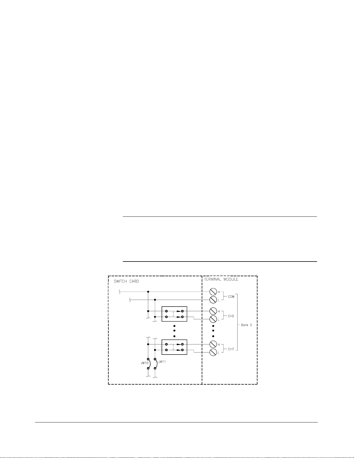
The channel relay switches are separated into eight banks. Each bank has
eight switchable channels and a COM channel. Each channel has a separate
HI (H) and LO (L) line. See figure 1-1 for a simpli fied schemati c diagram.
Banks are arranged as follows:
– Bank 0 includes channels 00 through 07 and COM.
– Bank 1 includes channels 10 through 17 and COM.
– Bank 2 includes channels 20 through 27 and COM.
– Bank 3 includes channels 30 through 37 and COM.
– Bank 4 includes channels 40 through 47 and COM.
– Bank 5 includes channels 50 through 57 and COM.
– Bank 6 includes channels 60 through 67 and COM.
– Bank 7 includes channels 70 through 77 and COM.
Each channel is switched (conn ected to its common) by closin g the
appropriate (latching) relays. Channels 0 through 7 can be switched to
COM for all banks. Any number of channels in each bank can be connected
to common at a time (except for one-wire mode).
User inputs/output s to each channel are via wire terminals . When a channel
is closed, it is internally connected to the COM terminal . When a channel is
opened, it is internally di sconnected. Open channels ar e not termi nated.
At power-on or reset, all channels are switched open (non-terminated) for
all banks only when using t he SCPI or C-SCPI driver. At pow er-off, all
relays remain in their present state.
12 Getting Started with the HP E1460A Multiplexer Chapter 1
Page 13

Figure 1-1. HP E1460A Multiplexer Block Diagram
Chapter 1 Getting Started with the HP E1460A Multip lexer 13
Page 14

Control Relays In addition to the channel switching relays, the switch card contains seven
control relays (numb ered 0990 to 0996). These relays switch the COM lines
of banks dependent on the mode selected. All relays are automatically
selected when the module is configured for the desired mod e, when using
[ROUTe:]FUNCtion <card_number> , <funct ion> command. For t h e
the
stand-alone swi tchbo x configu rat ion , this command must be used in
conjunction with the follo wing command s:
[ROUTe:]SCAN: MODE <mo de>
[ROUTe:]SCAN: PORT <
[ROUTe:]SCAN <
channel_list>
port>
If only using [RO UTe:]OPEN and [ROUTe:]CLOSe commands , t he
appropriate control relays must also be closed with the
For the scanning multimeter configu rat ion , the
card_number> , <function> in conjunction with the CONF igure and
<
INITiate or M EASure multimeter commands closes the appropriate control
[ROUTe:]FUNCt ion
CLOSe command.
relays. Refer to chapter 3 in this manual and chapte r 5 in the HP E1326B/
E1411B User’s Manual for more inform ati on about these commands. A
description of the relay’s functio n is provided bel ow:
Control
Relay Function
0990 Selects HI or LO terminal for one-wir e switchi ng.
0991 Connects Cable Tes t or one-wire LO REF terminal to the
one-wire LO COM terminal.
0992 Connects lower 32 channels (banks 0 - 3) to analog bus.
0993 Connects upper 32 channels (banks 4 - 7) to analog bus.
0994 Connects low er and upper analog buses together.
0995 Conne cts low er and upper comm on bu ses tog eth er
(64-channel, two-wi re operati on).
0996 Connects analog bus Guard to the LO line, on the upper
32 channels (banks 4 to 7).
14 Getting Started with the HP E1460A Multiplexer Chapter 1
Page 15

Basic Operating
Modes
The HP E1460A uses the channel and contro l relays on the swit ch card to
perform four basic operating modes:
• One-wire: switches either the HI or LO terminal of a channel in
banks 0 through 7, to the one-wire HI COM terminal. One-wire LO
COM is switched to the one-wire LO REF terminal. Only one
channel can be switched (closed) at a time. A maximum of 128
one-wire channels can be switched.
relay lows, then control relay 0990 switches and i t goes through all
channel relay highs.
SCAN goes through all channel
• Two-wire: switches both the HI and LO terminals of a channel in
banks 0 through 7, to the HI COM and LO COM terminals. A
maximum of 64 two-wire channels can be switched.
• Three-wire: switches both the HI and LO terminals of a channel in
banks 0 through 3, to the HI COM and LO COM terminals. This
mode also switches the LO terminal of the pair channel in banks 4
through 7, to the LO COM terminal. In addition, the low term inal of
the pair channel in banks 4 through 7 can be connected to the analog
bus Guard terminal. Banks are paired 0/4, 1/5, 2/6, and 3/7. A
maximum of 32 three-wire channels can be switched.
• Four-wire: swit ches bot h the HI and LO terminals of a channel in
banks 0 through 3, to the HI COM and LO COM terminals. Also
switches the HI and LO terminals of the pair channel in banks 4
through 7, to the HI COM and LO COM term inal s. Banks are paired
0/4, 1/5, 2/6, and 3/7. A maxim um of 32 four-wire channels can be
switched.
Typical
Configurations
Connections to the analog bus (for multimeter con nectio n) are provided on
both the relay switch card and term inal module.
For a SCPI environment, one or more multiplexer modules can be defined
as a switchbox or scanning multimeter. For a switchbox configuratio n, al l
multiplexer channels within the instrument can be addressed using a single
interface address. For a scanning multimeter configuration, both the
multimet e r and all multi pl exer mo dul es with in t he inst rument can be
addressed using a single interface address.
Chapter 1 Getting Started with the HP E1460A Multip lexer 15
Page 16

Warnings and Cautions
WARNING SHOCK HAZARD. Only service-trained person nel who are aware of
the hazards involved shoul d instal l, r emove, or confi gure the
multiplexer. Before you remove any install ed module, disconn e ct AC
power from the mainframe and from other modules that may be
connected to the multipl exer.
CHANNEL WIRING INSULAT ION. All channels tha t have a
common connection must be insulated so that the user is protected
from electrical shock in the event that two or more channels are
connected together. This means wiring for all channels must be
insulated as though each channel carries the vol tage of the highes t
voltage channel.
CAUTION MAXIMUM INPUTS. The maximum voltage that can be applied to any
terminal is 220 Vdc/250 V
any terminal is 1 A at 30 Vdc/V
maximum power that can be applied to any terminal i s 40 VA.
. The maximum current that can be applied to
rms
, or 0.3 A at 250 Vdc/V
rms
rms
. The
STATIC ELECTRICITY. Static electricity is a major cause of comp onent
failure. To prevent damage to the electrical components in the multiplexer,
observe anti-static techniq ues whenever removing a module from the
mainframe or whenever working on a module.
Configuring the Multiplexer
HP plug-in modules i nst alled i n an HP mainframe or used with an HP
command module are treated as independent inst rument s each having a
unique secondary HP-IB address. Each instrument is also assig ned a
dedicated error queue, input and output buffers, stat us registe rs and, if
applicable, dedicated mainframe/com mand modul e memory sp ace for
readings or data. An instrumen t may be composed of a singl e plug -in
module (such as a counter) or multip le plu g-in m odul es (for a switch box
or scanning mul timeter instrum ent).
16 Getting Started with the HP E1460A Multiplexer Chapter 1
Page 17

Setting th e Logical
Address Switch
Note The address switch selected valu e must be a multi pl e of 8 if the module is
The logical address switch (LADDR ) factory settin g for the HP E1460A
is 112. You may have changed the sett in g during mod ule in stal lati on.
Valid address values are from 1 to 255. If the multip lexer is used wi th
an HP E1406A Command Modu le in a C-size mai nframe, r efer to the
HP C-Size VXIbus Systems Inst all at ion and Getting Star ted Gui de for
addressing information. Otherwise, use figure 1-2 to change the setting.
the first module in a switchbox used wit h a VXIbus command module, and
being instructed by SCPI commands.
Figure 1-2. Setting the Logical Address Swi tch
Chapter 1 Getting Started with the HP E1460A Multip lexer 17
Page 18

Setting th e S tatus
Register Switch
Four bits of the S tatus Re giste r (bits 10- 13) define whet her the multiplexer
module is set for one- , two- , three- , or f our-wire switching. To ensure proper
operation, set the status register switch a s shown in figure 1-3.
Figure 1-3. Setting the Status Register Switch
18 Getting Started with the HP E1460A Multiplexer Chapter 1
Page 19

Setting th e
Interrupt Priority
Note The interrupt priority jumper MUST be installed in position 1 when using the
The multiplexer module generates an interrupt after a channel has been
closed. These interrupts are sent to, and acknowledgments are received
from, the command modul e (for example, HP E1406A) via th e VXIbus
backplane interrupt lines.
For most application s where the multiplexer modu le is instal led in an
HP 75000 Series C mainframe, the interrupt priorit y jumpe r does not have
to be moved. This is because the VXIbus interrupt lines have the same
priority, and interrupt priorit y is establi shed by install ing modules in slot s
numerically closest to the command m odul e. Thus, slot 1 has a higher
priority than slot 2, slot 2 has a high er priorit y than slot 3, and so on.
Refer to figure 1-4 to change the interrupt priority. You can select eight
different interrupt priority levels. Le vel 1 is the lowest priority and Level 7 is
the highest priority. Level X disables the interrupt. The module’s factory
setting is Level 1. To change, remove the 4- pin jumper (HP P/N 1258-0247)
from the old priority location and reinstall in the new priority location. If the
4-pin jumper is not used, the t wo jumpe r loc ations must have the same inte rrupt
priority level selected.
HP E1405/06 command module. Le vel X interrupt priority should not be used
under normal operating conditions. C hanging the pr iority level jumper is not
recommended. Do not change unless speci fically i nstructe d to do so.
Figure 1-4. Setting the Interrupt Priorit y
Chapter 1 Getting Started with the HP E1460A Multip lexer 19
Page 20

Configuring the Switch Card Wire Jumpers
The relay switch card has t hirt een factory insta lle d wir e jumpe rs (refer t o
figures 1-1 and 1-5) that connect C OM line s of ba nks together to form dual
1x32 channel configurations. These wir e jumpe rs can be c hanged t o
reconfigure the switch card to various 8-channel or 16-channel configurations.
Note It is only necessary to change the wire jumpers when reconfiguring the
switch card for groups of eight or 16 channels (from 32). DO NOT
CHANGE the wire jumper positions unless instructed to do so in the
desired operating procedures.
With the exception of JM1, wire jumpers are changed in pairs. Functions of
the wire jumpers are as foll ows:
JM1: Used during cable test (discuss ed in Chapter 2)
JM2/JM3: Used to connect the COM lines of bank pairs 0/1 and 2/3
JM4/JM5: Used to connect the COM lines of bank pairs 4/5 and 6/7
JM10/JM11: Used to connect the COM lines of banks 0 and 1
JM12/JM13: Used to connect the COM lines of banks 2 and 3
JM14/JM15: Used to connect the COM lines of banks 4 and 5
JM16/JM17: Used to connect the COM lines of banks 6 and 7
Figure 1-5. Switch C a rd Wire Jumper Settings
20 Getting Started with the HP E1460A Multiplexer Chapter 1
Page 21

To reconfigure the relay switch card, proceed as follows:
1. Positio n the switch c ard on a flat surface.
2. Using a TORX T-10 drive r, remove th e six screws (HP part number
0515-1135).
3. Carefully lift shield to expose the printed circuit board.
4. Configure the wire jumpers as required usi ng tabl es 1-1 an d 1-2.
Table 1-1 lists the jumper posit ion s for banks 0 to 3, and table 1-2
lists the jumper posi ti ons for banks 4 to 7. If installin g new jump ers,
use “zero-ohm resistors” or No. 22 AWG copper wire.
For example, to configure banks 0, 1, 2, and 3 as 1x8 multiplexers
and banks 4, 5, 6, and 7 as 1x16 multiplexers, the correct jumper
position s would be as follows :
Jumpers = JM14,15,16,17 No Jumpers = JM2,3,4,5,10,11,12,13
5. Replace shield and re -install the six screws.
Table 1-1. Bank 0 to 3 Jumper Configurations
BANK NUMBER =
JUMPER CONFI GURATI O N JM NUMBER (0 = Jumper, 1 = No Jumper)
Bank 0 Bank 1 Bank 2 Bank 3 1 2 3 4 5 10 11 12 13 14 15 16 17
1x32* 1x32* 1x32* 1x32* - 0 0 - - 0 0 0 0 - - - -
1x16 1x16 1x16 1x16 - 1 1 - - 0 0 0 0 - - - -
1x8 1x8 1x8 1x8 - 1 1 - - 1 1 1 1 - - - 1x8 1x8 1x16 1x16 - 1 1 - - 1 1 0 0 - - - -
1x16 1x16 1x8 1x8 - 1 1 - - 0 0 1 1 - - - -
* factory setting
Table 1-2. Bank 4 to 7 Jumper Configurations
BANK NUMBER =
JUMPER CONFI GURATI O N JM NUMBER (0 = Jumper, 1 = No Jumper)
Bank 4 Bank 5 Bank 6 Bank 7 1 2 3 4 5 10 11 12 13 14 15 16 17
1x32* 1x32* 1x32* 1x32* - - - 0 0 - - - - 0 0 0 0
1x16 1x16 1x16 1x16 - - - 1 1 - - - - 0 0 0 0
1x8 1x8 1x8 1x8 - - - 1 1 - - - 1 1 1 1
1x8 1x8 1x16 1x16 - - - 1 1 - - - - 1 1 0 0
1x16 1x16 1x8 1x8 - - - 1 1 - - - - 0 0 1 1
* factory setting
Chapter 1 Getting Started with the HP E1460A Multip lexer 21
Page 22

Note When wire jumpers JM10 through JM17 ar e removed, the odd-num bered
banks can no longer be connected to the analog bus. For example, if JM10
and JM11 are removed, then bank 1 can no longer be connected to the
analog bus terminals (except through user wiring).
When wire jumpers JM2 through JM 5 are removed, then banks 2/3 and 4/5,
respectively, can no longer be connected to the analog bus. For example, if
JM2 and JM3 are removed, then banks 2 and 3 can no longer be connected
to the analog bus terminals (except through user wiring).
Connecting the Analog Bus
Figure 1-6 shows how to connect the analog bus between multiple
multiplexer modules and to the HP E1411B Multim eter. Use cable
(HP part number E1400-61605 ) to connect th e analog bus of all the modules.
Note The analog bus can also be wired to the terminal module. See “Screw-type
Terminal Module” on page 24 for more information.
Figure 1-6. Analog Bus Cable Connecti ons
22 Getting Started with the HP E1460A Multiplexer Chapter 1
Page 23

Installing the Multiplexer in a Mainframe
The HP E1460A may be installed i n any slo t (except slo t 0) in a C-size
VXIbus mainframe. Refer to figure 1-7 to install the multiplexer in a
mainframe.
NOT E: The extraction le vers will
not seat the backplane co nnec to rs
on older VXIbus mainfram es. You
must manual ly seat the conn ector s
by pushing in the mod ule unt il the
front panel is flush with the front of
the mainfram e. The extractio n
levers may be used to guide or
remove the multiplexer.
Figure 1-7. Installing the Mu ltip l exer in a VXIbus Mainframe
Chapter 1 Getting Started with the HP E1460A Multip lexer 23
Page 24
Available Terminal Modules
The HP E1460A 64-Channel Relay Multi pl exer is compris ed of a relay
switch card and a screw-type standard terminal m odul e. If the screw-type
terminal module is not desired, a crimp-and-insert terminal module
(Option A3E) is available (see page 25). If the crimp-and-insert terminal
module without the HP E146 0A relay switch card is desired, order HP part
number E1460-80012 . See figure 1-10 on page 27 for the multiplexer’s
connector pin-out which mates to the termin al mod ule.
Screw-type
Terminal Module
Wirin g Gui delines
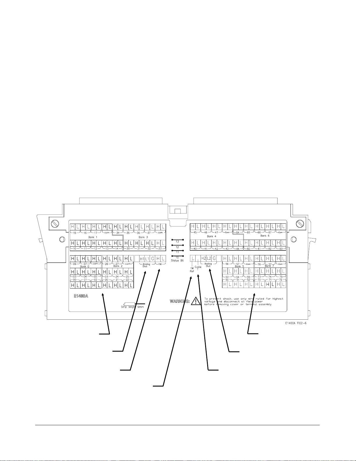
Figure 1-8 shows the multiplexer’s stand ard screw-type terminal module
connectors and associated bank numbers, channel nu mbers, and line
designations . Use the following gui deli nes for wir e connection s.
• Be sure that wires make good connections on screw terminals.
• Maximum terminal wire size is No. 16 AWG. When wiring all
64-channels, a smaller gauge wire (20-22 AWG) is recommended.
Wire ends should be stripped 6mm (
single strands from shorting to adjacent terminals.
≈ 0.25 in .) and tinned t o prevent
Bank 0 - 3 Terminals Bank 4 - 7 Terminals
Analog Bus Terminals Analog Bus Terminals
1-Wire Terminals Cable Test Termina l
1-Wire Low Ref Termina l
Figure 1-8. HP E1460A Standard Screw-type T ermin al Module
24 Getting Started with the HP E1460A Multiplexer Chapter 1
Page 25

Terminal Module
Option A3E
Option A3E can be ordered if a crimp-and-insert terminal module is desired.
This allows you to crimp conne ctors ont o wires which are then inserte d
directly into the mul tiplexer’s mating connector. Refer to the pin-out
diagram (figure 1-10) on pag e 27 to make th e conn ect ions.
Figure 1-9. Crimp-and-Insert Connecto r
Crimp-and- Insert
Termina l Module
Accessories
Single-Conductor and
Contact
Shielded -Twisted-Pair
and Contacts
The following accessories are necessary for use with crimp-and-i nsert
Option A3E:
A crimp-and-insert contact is crimped onto one end of a wire. The other
end is not terminated. Order HP 91510A.
Length: 2 meters
Wire Gau ge: 24 AW G
Quantity: 50 each
Insulation Rating: 105°C ma x
Voltage: 300 V
A crimp-and-insert contact is crimped onto each conductor at one e nd of a
shielded-twisted-pair cable. The ot her end is not terminated. Order HP 91511A.
Leng th: 2 meters
Wire Gauge: 24 AWG
Outside Diameter: 0.1 inches
Quantity: 25 each
Insulation Rating: 250 °C max
Voltage: 600 V
Chapter 1 Getting Started with the HP E1460A Multip lexer 25
Page 26

Jumper Wire and
Contacts
A crimp-and-insert contact is crimped onto each end of a single conductor
jumper wire. This jumper is typi cally us ed to tie two pi ns together in a
single crimp-and-ins ert connector. Order HP 91512A.
Length: 10 cm
Wire Gau ge: 24 AW G
Quantity: 10 each
Insulation Rating: 105°C ma x
Voltage: 300 V
Crimp-and- Ins e rt
Contacts
These contacts may be crimped on to a conduct or and then inse rted int o a
crimp-and-insert conn ect or. The crimp tool kit is required to crimp t he
contacts onto a conductor and remove the contact from the connector. Order
HP 91515A
Quantity: 250 each
Wire Gauge Rang e: 20 - 26 AWG
Plating: Gold Plate d Contact
Maximum Current: 2A at 70°C
Crimp-and-Insert Tools The hand crimp tool (part number HP 91518A) is used for crimping
contacts onto a conductor. The pin extractor tool (part number HP 91519A)
is required for removing cont a cts from the crimp -and-ins ert conne ctor.
These products are not inclu ded with Option A3E or with the termi nal
option accessories l iste d earlier.
Extra Crimp-and-Insert
Connect ors
The crimp-and-insert connect or is normal ly suppl ied wi th Optio n A3E.
Contact Hewlett-Packard Company if additi onal connectors a re needed.
Order HP 91484B.
26 Getting Started with the HP E1460A Multiplexer Chapter 1
Page 27
Connecting User Inputs
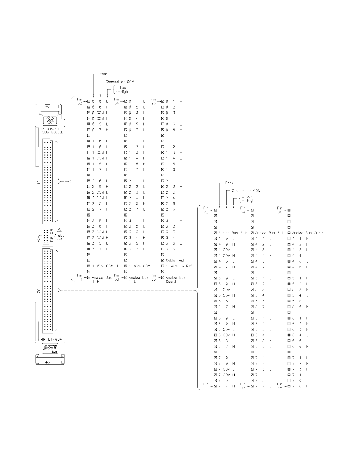
Figure 1-10 shows the front panel of the HP E1460A and the multiplexer’s
connector pin-out which mates to the termin al mod ule.
Figure 1-10. HP E1460A Multiplexer Pin-out
Chapter 1 Getting Started with the HP E1460A Multip lexer 27
Page 28

Attaching a Terminal Module to the Multiplexer
28 Getting Started with the HP E1460A Multiplexer Chapter 1
Page 29

Wiring a Terminal Module
The following il lu strati ons show how to connect field wiring to the terminal
module.
Continued on next page
Chapter 1 Getting Started with the HP E1460A Multip lexer 29
Page 30

30 Getting Started with the HP E1460A Multiplexer Chapter 1
Page 31

Programming the Multiplexer
The multiplexer modules are programmed either in a switchbox or scanning
multimete r configurati on. To program the multip lexer m odu les usi ng SCP I
commands, you must choose the controll er language, interface address, and
SCPI commands to be used. Guidelines to choose SCPI comm ands for the
multiplexer follow. See the C-Si ze VXIbus Syst ems In sta ll ati on an d Getti ng
Started Guide for interface addressing and controller language information .
Note This discussi on appl ies to SCPI prog rammi ng. See Appendix B,
“Register-Based Programming” for details on multiplexer mod ule r egiste rs.
Specifying SCPI
Commands
Multiplexer
Channel Addresses
Multiplexer Card
Numbers
To address specific channels withi n a multip lexer modu le in a switchbox or
scanning multimeter configurati on, you must:
• Send the appropriate SCPI command stri ng to the swi tchbo x or
scanning multimeter (for example,
CLOSe, O PEN, and so on).
• Specify the channel address.
For the HP E1460A, the channel address ( channel _list ) has t he form :
– (@ssbc) for the two-wire, three-wire, and four-wire modes.
– (@ss0hbc) for the one-wire mode.
– (@ss099c) for the control relays.
where
ss = card number (01-99)
0h = LO or HI terminal (0-1)
b = bank number (0-7)
c = number 0-7 for switching relays, and 0-6 for control relays
The card number identifi es the mod ule wit hi n a switchbox or s cannin g
multimeter configurati on. The card number assigned depends on the
configuration. Leading zeroes can be ignored for the card number.
• Single-mo du le Swi tch box . In a sing le-mod ule swi tchbo x
configuration, the card number is always 01.
• Multiple -modu le Swi tch box . In a m ultiple-module swi tchbox
configuration, multiplexer mod ules a re set to successive logi cal
addresses. The multiplexer module wit h th e lowest logi cal address is
always card number 01. The card number with the next successi ve
logical address is 02, and so on. Figure 1-11 illustrates the card
numbers and logical addresses of a typical multi ple-mo dul e
switchbox configu ration .
Chapter 1 Getting Started with the HP E1460A Multip lexer 31
Page 32

Figure 1-11. Card Numbers in a Multiple-modul e Switch box
• Multiple-module Scanni ng Multimeter. In a multiple-module
scanning multimeter configuration, mod ules a r e assigned successive
logical addresses beginning with the multimeter. The multimeter
module is always card number 00, the mult ipl exer module with the
next lowest logical address is always card number 01, the next
successive logical add ress is card number 02, and so on. Figure 1-12
illustrates the card numbe rs and logic al addresses of a typical
multiple-modu le s cannin g multi met er configuratio n.
Figure 1-12. Card Numbers in a Multiple-module Scanning Multimeter
The logical addresses noted in figures 1-11 and 1-12 appl y to modules
installed in an HP 75000 Series C Mainframe wit h an HP E1406A
Command Modu le. See the C-Size VXIbus Systems Inst al lat io n and Gett in g
Started Guide for more information on switchbox es, scanning m ult im eters,
and logical addressing. For uses in other sys tems or mainframes, see the
appropriate manuals.
32 Getting Started with the HP E1460A Multiplexer Chapter 1
Page 33

Low or High
Terminal
The LO or HI terminal number is specified in one -wire mode onl y, and
identifies what termi nal wi ll be used during one-wir e switching.
• 00 is specified to use the LO (L) terminal of the bank and channel
selected. Defaults to LO terminal if not entered.
• 01 is specified to use the HI (H) terminal of the bank and channel
selected.
The LO or HI terminal number is only used when in the one-wir e mode, and
can be omitted when the low termi nal i s the desired select ion . Only valid
terminals can be accessed in a channel list.
Bank Number The bank number ident ifi es what bank of eight chan nels wi ll be affected
during switching. The bank numbe rs are 0 to 7 for one- and two-wire
modes, and 0 to 3 for three- and four-wire modes. Only valid banks can be
accessed in a channel list.
Closing, opening, or querying banks 4 to 7 when operating in three- and
four-wire modes will generate an error.
Channel Number The channel number identifies what channel wil l be switched to its COM
terminal. Channel numbe rs are 0 to 7. Only valid channels can be accessed
in a channel list.
Chann el Address
Examples
When switching the control relays, the channel number (0 to 6) identifie s
what control relay will be switched ( refer to figure 1-1).
The channel address can be specified in the following forms:
One-wire mode only:
– (@ss0hbc) for a single chan nel;
– (@ss0hbc,ss0hbc) for multiple channels;
– (@ss0hbc:ss0hbc) for sequential channels;
– (@ss0hbc:ss0hbc,ss0hbc:ss0hbc) for groups of sequential channels;
– or any combination of th e above.
Two-, three-, or four-wire modes
(and control relays whe re b = 099):
– (@ssbc) for a single channel;
– (@ssbc,ssbc) for multiple channels;
– (@ssbc:ssbc) for sequential channels;
– (@ssbc:ssbc,ssbc:ssbc) for groups of sequenti al ch an nels;
– or any combination of the above.
Note The leading zero in the card number can be ignored.
Chapter 1 Getting Started with the HP E1460A Multip lexer 33
Page 34

Example Multiplexer
Module Channel List
In one-wire mo de:
CLOSe (@10173) Connect card 01, bank 7, channel
3 HI terminal to the one-wire HI
COM terminal.
In two-wire mode:
CLOSe (@173,176) Connect card 01, bank 7, channels
3 and 6 HI and LO terminals, to
bank 7 HI and LO COM terminals.
In three-wire mode:
CLOSe (@133:136) Connect card 01, bank 3, channels
3 through 6 HI and LO termi nal s,
to bank 3 HI and LO COM
terminals. Al so con nect bank 7,
channels 3 through 6 LO terminal ,
to bank 7 LO COM terminal.
In four-wi re mode:
CLOSe (@133:136,233:236) Connect card s 01 and 02, bank 3,
channels 3 through 6 HI and LO
terminals, t o bank 3 HI and LO
COM terminals. Also, connect
bank 7, channels 3 through 6 HI
and LO termi nals, to bank 7 HI
and LO COM terminals.
Control relays:
CLOSe (@10995) Connect s the upper and l owe r 32
channels together for a 64-channel
two-wire mul ti pl ex e r.
SCPI Command
Format Used in
This Manual
You can send SCPI commands in either short or long form. A long form
example is:
CLOSe (@123)
The same command shown wit hout the low er case letters is the short form.
The command then becomes:
CLOS (@123)
Some commands in this manual are shown with brackets ([ ]). These are
implied th at you do not need to execut e. Note that the brackets are not part
of the command, and are not sent to the instrum en t. For exampl e, th e
ROUTe command is an impli ed command and is shown h ere as:
[ROUTe:]CLOS (@123)
Thus, to execute these commands, simply enter:
CLOS (@123)
See chapter 3 for more explanatio n about SCPI command s and how to send
them.
34 Getting Started with the HP E1460A Multiplexer Chapter 1
Page 35

Initial Operation
Example Reset the switchbox and close card 01 bank 0 channel 2 (to COM).
Use the following program example to verify init ial multi plexer mod ule
operation by closing a channel and querying channel closure. The example
first resets the switchbox and then closes bank 0, channel 2 of a single
multiplexer module (card number 1) in the switchbox. The program next
queries the channel closure state. A returned "1" shows that the command
to close the channel has been sent to the switchbox. A returned "0" shows
that the command to close the channel has no t been sent to the switchbo x.
The computer used in the example is an HP Series 200/300 compu ter with
HP BASIC as the program language. The computer interfaces to the
mainframe using the Hewlett-Packard Interface Bus (HP-IB).
1
The HP-IB
interface select code is 7, the HP-IB primary address is 09, and the HP-IB
secondary address is 14. Refer to the C-Size VXIbus Systems Inst al lat io n
and Getting Started Guide for addressing information.
10 OUTPUT 70914;"*RST" !Resets the module; sets all relays
to open
20 OUTPUT 70914;"CLOS (@102)" !Connect ban k 0 channe l 2 HI and
LO terminals of bank 0 to COM HI
and LO terminals
30 OUTPUT 70914;"CLOS? (@102)" !Query channel 02
40 ENTER 70914;Value !Enter results into Value
50 PRINT Value !Display results (shou ld return " 1")
60 END !Terminate program
1 HP-IB is Hewlett-Packard’s implementat ion of IEEE St d 488. 1-1 987
Chapter 1 Getting Started with the HP E1460A Multip lexer 35
Page 36

Notes
36 Getting Started with the HP E1460A Multiplexer Chapter 1
Page 37

Using the HP E1460A Multiplexer
Using This Chapter
This chapter uses typical examples to show how t o use the mult ipl exer
module. This chapter contains the following sections:
• Multiplex er Comm an ds . . . . . . . . . . . . . . . . . . . . . . . . . . . . . Page 37
• Reset Conditions . . . . . . . . . . . . . . . . . . . . . . . . . . . . . . . . . . Page 38
• Switching Channels . . . . . . . . . . . . . . . . . . . . . . . . . . . . . . . . Page 38
• Scanning Channels. . . . . . . . . . . . . . . . . . . . . . . . . . . . . . . . . Page 44
• Measurement and Test Configurations . . . . . . . . . . . . . . . . . Page 55
• Recalling and Saving States. . . . . . . . . . . . . . . . . . . . . . . . . . Page 60
• Detecting Error Conditions . . . . . . . . . . . . . . . . . . . . . . . . . . Page 60
• Synchronizing the Multiplexer . . . . . . . . . . . . . . . . . . . . . . . Page 62
• Querying the Multiplex er. . . . . . . . . . . . . . . . . . . . . . . . . . . . Page 63
Multiplexer Commands
Chapter 2
Table 2-1 explains some of the commands us ed in this chapter. Refer to
chapter 3 for additional information about the command s listed below.
Table 2-1. Multiplexer Commands Used in Chapter 2
Command Description
INITiate[:I MMediate]
OUTPut:TTLTrg
OUTPut[:EXTer nal][:STAT e] ON Enables the selected outpu t to trigger pulses from the command m odule ’s
[ROUTe:]CLO Se <
[ROUTe:]CLO Se? <
[ROUTe:]FUNCtion <
[ROUTe:]OPEN <
[ROUTe:]SCAN <
[ROUTe:]SCAN:PO RT Closes bank COM terminals to the analog bus during a scan.
[ROUTe:]SCAN:M O D E Sets the scan mode to volts, 2-wire ohms, or 4-wire ohms.
TRIGger: SOURce <
*CLS Clears all switchbox status registers and error queue.
*ESE En ables ev ent stat us regist er.
*RST Re sets the hardwar e and softwa re to a known state.
*SRE Enables status register .
n[:STATe] ON
chan ne l_list> Closes the channels in the channel_l ist.
channel_list> Queries the state of the closed cha nnels in the chann el _list .
card_number> , <functio n>
channel_list> Opens the ch anne ls in the c ha n nel_list.
channel_list>
source> Selects the trigger so urce to adva nce t he sc an.
NOTE: SCPI comma nds wit hin the squa re bracket s ([ ]) are implied and are, ther efore , not requir ed.
Starts the scan seque nce an d closes the firsat channel in the
Enables the sele cted out pu t to trigge r pulses from the TTL Trigger bus
line specified.
"Trig Out" port.
Sets the oper at ing mo de to one- , two- , three- , or four-wire .
Defines the channels t o be scanned . Channels specified in the
channel_list are closed one at a time.
channel_l ist.
Chapter 2 Using the HP E1460A Multiplexer 37
Page 38

Reset Conditions
Parameter Default Description
ARM:COUNt 1 Number of scanning cycles is one.
INITiate:CO NTinuou s OFF Number of scanning cycles is set by ARM:COUNt.
When the multiplexer is switched on or *RST (reset), all bank channels are
set to open, and the current channel_list for scanning is invalidat ed .
Table 2-2 lists the parameters and default values for the functions described
in chapter 2.
Table 2-2. *RST (Reset) Default Cond ition s and Valu es
OUTPut:ECLTrg
OUTPut[:EXTernal] [ :ST ATe] OFF Trigger output from external sources is disabled.
OUTPut:TTLTrg
[ROUTe:]SCAN: MOD E NONE Channel list volts/ohms measureme nts disabled .
[ROUTe:]SCAN: POR T NONE Analog bus port connection disabled .
TRIGger:SOURce IMM Will advance scanning cycles auto ma tically.
n[:STATe]
n[:STATe]
*RCL, *RST, and *SAV do not affect the operating mode as set by the
FUNCtion comm and.
Switching Channels
For general purpose switching, connect or disconnect signals in either the
one-, two-, three-, or four-wire modes by opening or closing specific
channel(s).
OFF Trigger output from ECLT sources is disabled.
OFF Trigger output from TTLT sources is disab le d.
• Use FUNCtion <card_number> , < fu ncti on> to confi gure th e
multiplexer switch with these modes:
WIRE1 | WIRE2 | WIRE2X 6 4 | WIRE3 | WIRE4 replaces <function>.
Note For more information, see the [ROUTe:]FUNCtion command on pag e 79 .
There is no need to send the
register switch (see “Setting the Status Register Switch” on page 18) is set
to the correct operating mode.
[ROUTe:]FUNCt io n command if the status
• Use CLOSe <channel_list> to close bank channel(s), and
OPEN <channel_list> to open bank channel(s).
Channel_list has the form (@ss0hbc) where ss = card number
(00-99), 0h = one-wire mode only HI/LO switching (00 or 01),
b = bank number (0-7), and c = channel number (0-7).
38 Using the HP E1460A Multiplexer Chapter 2
Page 39

Example: One-Wire
Mode Channe l
Switching
Note If the status register switch is set to one-wire operating mode, then the
This example illustr ates operating in one-wire mode. For the example, the
HI terminal is used. Bank 2 channel 1 is closed, conne ctin g the HI termin al
to the one-wire HI COM terminal. Figure 2-1 shows how th e mult ip lexer is
configured. For one-wire operation, the cont rol relays are set as follows:
• 0990 depends on HI or LO terminal selection.
• 0991/0995 are set closed.
• 0992 will close when SCAN:PORT ABUS is selected during a scan
(see “Scanning Channels” on page 44).
• 0993/0994/0996 remain in current state (open if not changed after
*RST).
To connect the HI terminals of bank 2 channel 1 to the one-wire HI COM
terminal, execute:
FUNC 1,WIRE1 Configures the mu lt iple xe r (c ard
01) for one-wire operation.
CLOS (@10121) Connects the HI termina l of bank 2
channel 1 to the one-wire HI COM
terminal.
FUNC 1,WIRE1 command is not required. When operating in the one-wire
mode, only one channel at a time can be closed .
Figure 2-1. Example: One-W ire Mod e Chan n el Sw itch ing
Chapter 2 Using the HP E1460A Multiplexer 39
Page 40
Example: Two-Wire
Mode Channe l
Switching
This example illustrates operating in two-wire mode. The HI and LO
terminals of bank 0 channels 0 and 7 are closed, connecting them to the
bank 0 HI and LO COM terminals. Figure 2-2 shows how th e mult ip lexer is
configured. For two-wire operation, the control relays are set as follows:
• 0990/0991 are opened if using the SCAN <channel_li st> comm and
SCAN:PORT ABUS and SCAN:MODE <mode>. Mode can be
with
RES, VOLT, or NONE. 0990/0991 are left in their presen t state if
mode is
FRES.
• 0992/0993 will clo se when SCAN:PORT ABUS is selected during a
scan (see “Scanning Channels ” on page 44).
• 0994/0995/0996 remain in their pr esent state with the followin g
exceptions. 0994 is closed in
WIRE2X64 (2x64 config ur atio n), 09 94 is closed in the RES and
NONE modes . In the F RES mode, 09 94 and 099 5 are opened.
0996 closes and connects COM to LO for voltage measurements with
MEASure or INITiate SCPI commands in a sc anni ng multimeter.
the
To connect the HI and LO terminals of bank 0 channels 0 and 7 to the bank 0
COM terminals, execute:
FUNC 1,WIRE2 Configures the multiplexer (card #1)
CLOS (@100,107) Connects the HI and LO te rminals of
RES mode. If FUNC <card_number>,
for two-wire operation.
bank 0 channels 0 and 7 to bank 0
COM terminals.
Note If the status register switch is set to the two-wire operating mode, then t he
FUNC 1,WIRE2 command is not requir ed. The WIRE2X64 command can
be used instead of closing contro l relay 0995 to configu re the card to a
single 64-channel multiplexer.
Figure 2-2. Example: Two-W ire Mo de Chan nel Switch in g
1
1 Available only with HP E1405B ROM Rev. A.08. 00 or later and HP E1406A (Swit chbo x rev. A.06. 00 or later).
40 Using the HP E1460A Multiplexer Chapter 2
Page 41

Example: Three-Wire
Mode Channe l
Switching
This example illust rates the th ree-wire mode. The HI and LO terminals of
bank 0 channel 0 are closed, connecting them to the bank 0 COM terminal s.
The LO terminal of bank 4 channel 0 is closed, connecting it to the bank 4
LO COM terminal. Figure 2-3 shows how th e mult ip lexer i s configu red.
For three-wire operation, the control relays are set as follows:
• 0990/0991 are set open when SCAN <channel_list> is executed.
• 0992/0993/0996 will close when SCAN:PORT ABUS i s selected
during a scan. 0992 and 0993 a r e op en ed wh en not
ABUS
(see “Scanning Channels” on page 44).
SCAN:PORT
• 0994/0995 are set open when SCAN <channel_list> is executed.
To connect the HI and LO terminals of bank 0 channel 0, and the LO
terminal of bank 4 channel 0 to their COM terminals, execute:
FUNC 1,WIRE3 Configures the mu lt iple xe r (c ard
CLOS (@100) Connects the HI and LO termin als
01) for three-wire operation.
of bank 0 channe l 0 to the ba nk 0
COM te rmi nal s, a n d the L O
terminal of bank 4, channel 0 to
the bank 4 LO COM terminal.
Note If the status register switch is set to three-wire operating mode, then the
FUNC 1,WIRE3 command is not required. In three-wire mode, banks are
paired 0/4, 1/5, 2/6, and 3/7. Do not connect user wiring to the HI terminal
in the upper bank pair (4-7), as this terminal is switched during three-wire
operation. Upper bank pair (4-7) channels cannot be switched or queried
while in this mode.
Figure 2-3. Example: Three-W ire Mode Chann el Switchin g
Chapter 2 Using the HP E1460A Multiplexer 41
Page 42

Example: Four-Wire
Mode Channe l
Switching
Note If the status register switch is set to four-wire operating mode, then t he
This example illustrates operating in four-wire mode. The HI and LO
terminals of bank 0 channel 0 are closed, connecting them to the bank 0
COM terminals. At the same time, the HI and LO termin als of bank 4
channel 0 are closed, connecting them to the bank 4 COM terminals.
Figure 2-4 shows how the multiplexer is configured. For four-wire
operation, the contro l relays a re set as follows:
• 0990/0991 are set op en when SCAN <channel_list> is executed.
• 0992/099 3 w ill clos e when SCAN:PORT ABUS is selected during a scan.
They are opened otherwise (see “Scanning Channels” on page 44).
• 0994/0995/0996 are set open when SCAN <ch annel _list > is executed.
To connect the HI and LO terminals of bank 0 channel 0, and the HI and LO
terminals of bank 4 channel 0 to their COM terminals, execute:
FUNC 1,WIRE4 Configures the multiplexer (card #1)
for four-wire operation.
CLOS (@100) Connects the HI and LO termin als
of bank 4 channe l 0 to the ba nk 4
COM terminals.
FUNC 1,WIRE4 command i s not requir ed. In four-wire mode, banks are
paired 0/4, 1/5, 2/6, and 3/7. Upper bank pair (4-7) channels cannot be
switched or queried whil e in this mode.
Figure 2-4. Example: Four-W ire Mo de Ch ann el Switch in g
42 Using the HP E1460A Multiplexer Chapter 2
Page 43

Comments Opening Channels. Use the previous exampl es to open channels by
substitu ting the
channel_list> command. For example, in the previo us two-wir e example,
<
the command would be:
Closing/ Op enin g Mul tip le Chan nels. To close or open multiple channels,
place a comma (,) between the channel numbers. To close or open a range
of channels, pl ace a colon (:) between the channel numbers. You can do
this for both single or mul ti pl e modul e swit ch boxes. See
on page 81 and [ROUTe:]CLOS e on page 77 for addit io nal in fo rmati on.
CLOSe <channel_list> comm and wit h th e OPEN
OPEN (@100,107).
[ROUTe:]O PE N
Query Open/Closed Channels. The
OPEN? <channel_list> comm ands det ermine if th e channel in the
CLOS? <channel_list> and
channel_list is open or closed, respectively . (The query command does
not determine if, in the event of a hardware failure, the channel remains
open/closed.) See
[ROUTe:]O PE N ? on page 83 and [ROUTe:]CLOSe ?
on page 79 for additio nal in formati on.
Control Relays. The control relays 099 0 to 0996 can also be switched
using the
is executed first. See
OPEN and CLOSe commands, provided the FUNCt ion command
[ROUTe:]OPEN on page 81 and [ROUTe:]CLOSe
on page 77 for additio nal in formati on.
FRES: When operating in one-wire mode, 4-wire resistance measurement
FRES) is not supported. See the [RO UTe:]SCAN:MO D E command on
(
page 85 for additional information.
Analog Bus Connection when Scanning. In all four modes of operation,
the analog bus can be connected during a scan using the
SCAN:PORT
command. In three-wire mode, the paired bank (4-7) channel LO terminal
can be connected to the analog bus Guard terminal. See the
[ROUTe:]SCAN: PORT command on page 87 for additional information .
Analog Bus Connection when Not Scanning. When opening and closing
individu al chan nels in all four mo des of ope ration , the analog bus can be
connected by switching the control relay s (0992-0994, 0996 ) using the
OPEN and CLOSe co mmands. Se e [ROUT e: ]OPEN on page 81 and
[ROUTe:]CLOSe on page 77 for addition al informatio n.
Relay Switch Card Configuration. In all modes of operation the relay
switch card wire jumpers can be c hanged to 1x8 or 1x16 configurations as
required. Refer to “Configuring the Switch Card Wire Jum pers” on page 20
for additional information.
Chapter 2 Using the HP E1460A Multiplexer 43
Page 44

Scanning Channels
Scanning the multiplexer mod ule channels consis ts of closing bank
channel(s) to the respective bank COM termi nal(s) one chan nel at a time.
Single scan, mu ltipl e scans (2 to 32767), or cont inuous scanning modes are
available.
The
The
Module’s "Trig Out" port , TTL Trigger bus lin es (0-7), or ECL Trigger bus
lines (0-1). Figure 2-5 illustrates th e scanning sequence.
TRIGger:SOURce command specifies the source to advance the scan.
OUTPut command c an be used to enable the HP E1406A Command
Figure 2-5. Sequence of Scanning Chann els
44 Using the HP E1460A Multiplexer Chapter 2
Page 45

Example: Scanning
Channels wit h System
Multimete r Using TTL
Trigger
This example uses the command mo dul e’s TT L Trigg er Bus lines to
synchronize multiplexer bank 0 channel 0, to bank 7 channel 7 closures to a
system mult imeter (HP E1411 B). For the example, a two-wire ohm s
measurement is performed. For measurement synchroni z atio n:
• HP E1406A TTL Trigger Bus line 0 is used by the multi plexer to
trigger the multimet er to perform a measurement.
• HP E1406A TTL Trigger Bus line 1 is used by the multi meter to
advance the multiplexer scan.
Figure 2-6 shows how to connect the multipl exer modul e to the mult imete r
module. For the example, use:
• an HP-IB select code of 7, primary address of 09, and secondary
address of 03 for the multimeter;
• an HP-IB select code of 7, primary address of 09, and secondary
address of 14 for the multiplexer;
• an HP Series 200/300 Comput e r with HP BASIC.
Figure 2-6. Scanning with System Multimeter using TTL Trigger Bus
Chapter 2 Using the HP E1460A Multiplexer 45
Page 46

10 !Dimension computer to store readings.
20 DIM Readings(1:64)
30 !
40 OUTPUT 70903;"*RST"
50 !
60 !the least accurate resolution (the largest value ) .
70 OUTPUT 70903;"CONF:RES AUTO,MAX"
80 !
90 !TTL Trigger bus line 0.
100 OUTPUT 70903;"TRIG:SOUR TTLT0"
110 !
120 !complete.
130 OUTPUT 70903;"OUTP:TTLT1:STAT 1"
140 !
150 OUTPUT 70903;"TRIG:COUN 64"
160 !
170 OUTPUT 70903;"*OPC?"
180 !
190 ENTER 70903;Opc
200 !
210 OUTPUT 70914;"*RST"
220 !
230 OUTPUT 70914;"FUNC 1,WIRE2X64"
Resets multimeter module to known state.
Configures the multimeter to measure resista nce using autorange at
Multimeter to perform measurement when trigger received on
Multimeter to cause trigger on TTL trigger bus line 1 when measurement
Multimeter to receive 64 triggers.
Multimeter operations complete.
Enters a "1" when complete.
Resets the multiplexer module to known state.
Configures multiplexer for 64 channel; closes control relay 0995.
240 !
250 !close complete.
260 OUTPUT 70914;"OUTP:TTLT0:STAT 1"
270 !
280 OUTPUT 70914;"TRIG:SOUR TTLT1"
290 !
300 !measurement on multimeter’s HI/LO terminals).
310 OUTPUT 70914;"SCAN:MODE VOLT"
320 !
330 !upper and lower four bank commons.
340 OUTPUT 70914;"SCAN:PORT ABUS"
350 !
360 OUTPUT 70914;"SCAN (@100:177)"
370 !
380 OUTPUT 70914;"*OPC?"
390 !
400 ENTER 70914;Opc
410 !
420 !results to output buffer when triggered.
Multiplexer to cause trigger on TTL trigger bus line 0 when channel
Multiplexer to advance scan when trigger received in TTL trigger bus line 1.
Sets switchbox measurement to volt (used to make 2-wire resistance
Closes contro l relays 992 and 993 connecting t he anal og bus to the
Defines channe l list to scan bank 0 chann el 0 to bank 7 chann el 7.
Multiplexer operations complete.
Enters a "1" when complete.
Places multim eter in wait-for- trigge r state. Will send measure me nt
Contin ued on next pag e
46 Using the HP E1460A Multiplexer Chapter 2
Page 47

430 OUTPUT 70903;"READ?"
440 !
450 !TTL Trigger bus line 0 which initiates the multim eter to make a
455 !measurement.
460 OUTPUT 70914;"INIT"
Closes bank 0 channel 0 and enables the scan; causes a trigger output on
Example: One-Wire
Scanning of E1460A
with Two-Wire Ohms
Function of E1412A
470 !
480 ENTER 70903;Readings(*)
490 !
500 PRINT Readings(*)
510 !
520 END
Enters measurement results.
Displays measurement result.
Terminate progra m.
The following exampl e prog ram, using a HP BASIC workstat ion and the
SCPI driver for the E1460A in the HP E1406A slo t 0 command mo dul e,
illustrates one-wi re scanning of the HP E1460A wi th the two-wire ohm s
function of the HP E1412 A (or HP E1410A). The TTL trigger bus lines a re
used to do the DVM triggering and the multiplexer channel advance.
10 !Program to illustrate one wire scanning of E1460A with two-wire ohms
20 !function of E1412A . This uses the stand alone switch box mode. The TTL
30 !trigger bus lines are used to do the DVM triggering and the MUX
40 !channel advance.
50 !
60 ASSIGN @Dvm TO 70903
70 ASSIGN @Mux TO 70914
80 DIM A$[80],Rdgs(1:64)
90 !
100 CLEAR @Dvm
110 CLEAR @Mux
120 OUTPUT @Dvm;"*RST;*CLS"
130 OUTPUT @Mux;"*RST;*CLS"
140 !
150 OUTPUT @Dvm;"FUNC:RES"
160 OUTPUT @Dvm;"TRIG:SOUR TTLT0"
170 OUTPUT @Dvm;"TRIG:COUN 64"
180 OUTPUT @Dvm;"OUTP:TTLT1:STAT ON"
190 OUTPUT @Dvm;"*OPC?"
200 ENTER @Dvm;Cp
210 OUTPUT @Dvm;"SYST:ERR?"
220 ENTER @Dvm;A$
230 PRINT A$
240 !
250 OUTPUT @Mux;"FUNC 1,WIRE1"
260 OUTPUT @Mux;"OUTP:TTLT0:STAT 1"
Contin ued on next pag e
Chapter 2 Using the HP E1460A Multiplexer 47
Page 48

270 OUTPUT @Mux;"TRIG:SOUR TTLT1"
280 OUTPUT @Mux;"SCAN:MODE RES"
290 OUTPUT @Mux;"SCAN:PORT ABUS"
300 OUTPUT @Mux;"SCAN (@100:177)"
310 OUTPUT @Mux;"*OPC?"
320 ENTER @Mux;Cp
330 OUTPUT @Mux;"SYST:ERR?"
340 ENTER @Mux;A$
350 PRINT A$
360 !
370 OUTPUT @Dvm;"INIT"
380 OUTPUT @Mux;"INIT"
390 OUTPUT @Dvm;"FETCh?"
400 ENTER @Dvm;Rdgs(*)
410 PRINT Rdgs(*)
420 END
For this example the followi ng resis tor valu es were connected to the
channels indicated, and the one-wire COM terminal.
1 KΩ on channel 0 0 HI
Ω on channel 00 LO
1.5 K
Ω on channel 01 HI
1.2 K
Ω on channel 01 LO
1.8 K
The remaining channels are open. The results are printed below.
+0, "No error"
+0, "No error"
1489.102 1786.67 9.9E+37 9.9E+37 9.9E+37 9.9E+37 9.9E+37 9.9E+37
9.9E+37 9.9E+37 9 .9E+37 9.9E+37 9.9E+3 7 9.9E+ 37 9.9E+37 9.9E+37
9.9E+37 9.9E+37 9 .9E+37 9.9E+37 9.9E+3 7 9.9E+ 37 9.9E+37 9.9E+37
9.9E+37 9.9E+37 9 .9E+37 9.9E+37 9.9E+3 7 9.9E+ 37 9.9E+37 9.9E+37
9.9E+37 9.9E+37 9 .9E+37 9.9E+37 9.9E+3 7 9.9E+ 37 9.9E+37 9.9E+37
9.9E+37 9.9E+37 9 .9E+37 9.9E+37 9.9E+3 7 9.9E+ 37 9.9E+37 9.9E+37
9.9E+37 9.9E+37 9 .9E+37 9.9E+37 9.9E+3 7 9.9E+ 37 9.9E+37 9.9E+37
9.9E+37 9.9E+37 9 .9E+37 9.9E+37 9.9E+3 7 9.9E+ 37 9.9E+37 9.9E+37
1003.129 1198.643 9.9E+37 9.9E+37 9.9E+37 9.9E+37 9.9E+37 9.9E+37
9.9E+37 9.9E+37 9 .9E+37 9.9E+37 9.9E+3 7 9.9E+ 37 9.9E+37 9.9E+37
9.9E+37 9.9E+37 9 .9E+37 9.9E+37 9.9E+3 7 9.9E+ 37 9.9E+37 9.9E+37
9.9E+37 9.9E+37 9 .9E+37 9.9E+37 9.9E+3 7 9.9E+ 37 9.9E+37 9.9E+37
9.9E+37 9.9E+37 9 .9E+37 9.9E+37 9.9E+3 7 9.9E+ 37 9.9E+37 9.9E+37
9.9E+37 9.9E+37 9 .9E+37 9.9E+37 9.9E+3 7 9.9E+ 37 9.9E+37 9.9E+37
9.9E+37 9.9E+37 9 .9E+37 9.9E+37 9.9E+3 7 9.9E+ 37 9.9E+37 9.9E+37
9.9E+37 9.9E+37 9 .9E+37 9.9E+37 9.9E+3 7 9.9E+ 37 9.9E+37 9.9E+37
48 Using the HP E1460A Multiplexer Chapter 2
Page 49

Example: Scanning
Channels with External
Device Using “Trig In”
and “Trig Out”
This example uses the command mo dul e’s " Trig In" and "Trig Out" ports to
synchronize the mult iplexer modul e bank 0 channel 0 to 2 closures to an
external multimeter. The multimeter’s reading storage capacity is used to
store measurement results. For measurement synchroni zation:
• HP E1406A "Trig Out" port is connected to the e xte rnal m ultimeter’s
"Ext Trig" port. This trigger signals the multi met er to make the
measurement.
• HP E1406A "Trig Out" port is connected to the external multimeter’s
"Voltmeter Complete" port. This tri gger c auses the multiplexer to
advance the scan.
Figure 2-7 shows how to connect the multipl exer modul e to the mult imete r.
For the example, use:
• an HP-IB select code of 7, primary address of 09, and secondary
address of 14 for the multiplexer;
• an HP-IB select code of 7, primary address of 22 for the digital
mult imeter;
• an HP Series 200/300 Comput e r with HP BASIC .
Figure 2-7. Scanning with External Devices Using
“Trig In ” an d “ T rig Out” Ports
Chapter 2 Using the HP E1460A Multiplexer 49
Page 50

10 !Configures the external multimeter to external trigger to measure DC
20 !volts and store readings.
30 OUTPUT 722;"TRIG EXT;DCV;MEM FIFO"
40 !
50 OUTPUT 70914;"*RST;*CLS"
60 !
70 OUTPUT 70914;"OUTP ON"
80 !
90 OUTPUT 70914;"TRIG:SOUR EXT"
100 !
110 OUTPUT 70914;"SCAN:MODE VOLT"
120 !
130 OUTPUT 70914;"SCAN (@10000:10015)"
140 !
150 !from E1406A "Trig Out" port which initiates the external multimeter to
160 !make a measurement. When the me asure ment is comp lete , the
170 !multimeter’s "Voltm eter Co mple te" port sen ds a trigger to the
175 !multiplexer to advance the scan.
180 OUTPUT 70914;"INIT"
190 Wait 1
200 !
210 FOR Channels = 1 to 16
220 !
230 ENTER 722;Results
Resets the multiplexer module to a known state.
Enable E1406A "Trig Out" port.
Sets switchbox trigger source to external triggering.
Sets switchbox measurement mode.
Define channel list.
Closes bank 0 channel 0 and enable s the sca n. Causes a trigger output
Start counting loop (16 channels).
Enter measurement result.
Example: Scanning
Multimeter
Configuration
240 !
250 NEXT Channels
260 !
270 END
Increment count and repeat measurement process for 16 measurements.
Terminate progra m.
This example uses the command mo dul e (HP E1406A), syst em mu lt imet er
(HP E1411B), and mu ltipl exer (HP E1460A) modul es to perform a DC
voltage measurement on all 64 channels in a scanning multimeter
configuration. In the scanning multimeter configuration, the multiplexer
module’s logi cal address must be set one numbe r higher than the mul timeter
module. Refer to figure 1-12 for more information.
Figure 2-8 shows how to connect the multipl exer modul e to the mult imete r
module. For the example, use:
• an HP-IB select code of 7, primary address of 09, and secondary
address of 03 for the scanning multi met er (multi met er/ mul ti pl exer);
• an HP Series 200/300 Comput e r with HP BASIC.
50 Using the HP E1460A Multiplexer Chapter 2
Page 51

Figure 2-8. Scanning Multimeter
10 !Dimension computer to store readings.
20 DIM Rdgs(1:64)
30 !
40 OUTPUT 70903;"*RST"
50 !
60 OUTPUT 70903;"ROUT:FUNC1,WIRE2X64"
70 !
75 !channels 0 to 2.
80 OUTPUT 70903;"MEAS:VOLT:DC? (@100:177)"
90 !
100 ENTER 70903;Rdgs(*)
110 !
120 FOR I = 1 TO 64
130 !
140 PRINT Rdgs(I)
150 !
160 !measurements.
170 NEXT I
180 !Terminate program.
190 END
Resets the scanning multime te r module to a known state.
Required to close co ntrol relay 0995 to acc ess upper 4 bank s.
Configures the scanning multimeter to measure voltage on bank 0
Enters measurement result.
Start counting loop (3 channels).
Displays measurement result.
Increment the count and repeats measurement process for a total of 3
Chapter 2 Using the HP E1460A Multiplexer 51
Page 52

Example: One-Wire
Mode When
Configured as
Scanning Multimeter
The following example pro gram, using an HP BASIC workstatio n and the
HP E1406A Command Mod ule, verifies th at the E1460A wil l work in
one-wire mode for resistance measurements with the E1411B when the two
are configured as a scanning multimet er.
10 !Program to verify that the E1460A will work in one-wire mode for
20 !resistance measurements with the E1411B, when the two are config ured
30 !as a scanning multimeter.
40 !
50 !
60 !must externally connect the HI current source banana jack to the HI
70 !input banana jack; and the LO current Source/COM to the LO input
80 !banana jack on the front panel of the E1411 B.
90 !
100 DIM A$[40],Rdgs(1:66)
110 ASSIGN @Dvm TO 70903
120 OUTPUT @Dvm;"*RST;*CLS"
130 WAIT 2
140 OUTPUT @Dvm;"*IDN?"
150 ENTER @Dvm;A$
160 PRINT A$
170 !
180 OUTPUT @Dvm;"ROUT:FUNC? 1"
190 ENTER @Dvm;A$
200 PRINT "If E1460A terminal module jumper 10 is cut, and jumpers 11,"
210 PRINT "12, and 13 are in place, ROUT:FUNC? will return ’WIRE1’."
220 PRINT A$
230 !
240 OUTPUT @Dvm;"MEAS:RES? (@10000:10101)"
250 ENTER @Dvm;Rdgs(*)
260 PRINT Rdgs(*)
270 END
NOTE: For this to work in either switchbox or scanning DVM mod e, you
HEWLETT-PACKARD,E1411B,0,A.04.02
If E1460A terminal modu le jum per 10 is cut, and jump ers 11, 12, and 13
are in place,
ROUT:FUNC? will return "WIRE1".
52 Using the HP E1460A Multiplexer Chapter 2
Page 53

1489.191 1786.768 9.9E+37 9.9E+37 9.9E+37 9.9E+37 9.9E+37 9.9E+37
9.9E+37 9.9E+37 9.9E+37 9.9E+37 9.9E+37 9.9E+37 9.9E+37 9.9E+37
9.9E+37 9.9E+37 9.9E+37 9.9E+37 9.9E+37 9.9E+37 9.9E+37 9.9E+37
9.9E+37 9.9E+37 9.9E+37 9.9E+37 9.9E+37 9.9E+37 9.9E+37 9.9E+37
9.9E+37 9.9E+37 9.9E+37 9.9E+37 9.9E+37 9.9E+37 9.9E+37 9.9E+37
9.9E+37 9.9E+37 9.9E+37 9.9E+37 9.9E+37 9.9E+37 9.9E+37 9.9E+37
9.9E+37 9.9E+37 9.9E+37 9.9E+37 9.9E+37 9.9E+37 9.9E+37 9.9E+37
9.9E+37 9.9E+37 9.9E+37 9.9E+37 9.9E+37 9.9E+37 9.9E+37 9.9E+37
1003.211 1198.744
All of the resistor values below were
connected to 1-W ire CO M:
1 K
Ω on channel 00 HI
Ω on channel 00 LO
1.5 K
Ω on channel 01 HI
1.2 K
Ω on channel 01 LO
1.8 K
Example: Using the
Scan Complete Bit
The scan complete bit (bit 8) can be used in the Operation Status Register of
a switchbox to determi ne when a scanning cycle co mpl etes (no ot her bits in
the register apply to the switchbo x). Bit 8 has a decimal value of 256 and
you can read it directly with the
STATus:OPERation[:EVENt]? command on page 90, for an example).
When enabled by the
STAT:OPER:ENAB 256 command, the scan complete
STAT:OPER? command (refer to the
bit will be reported as bit 7 of the Status Byte Regi st er. Use the HP-IB
Serial Poll or the IEEE 488.2 Common Command
*STB? to read the Status
Byte Register.
When bit 7 of the Status Byte Registe r is enabled by the
*SRE 128 common
command to assert an HP-IB Service Request , you can interrupt the
computer when the scan complete bit is set, after the scannin g cycle
completes. This allo ws the cont roll er to do other operati ons whi le th e
scanning cycle is in progress.
The following example moni to rs bit 7 in the Status Byte Register to
determine when the scanning cycle compl etes. For the example, use:
• an HP-IB select code of 7, primary address of 09, and secondary
address of 14 for the multiplexer;
• an HP Series 200/300 Comput e r with HP BASIC.
Chapter 2 Using the HP E1460A Multiplexer 53
Page 54

10 !Clear all switchbox status structure.
20 OUTPUT 70914;"*CLS"
30 !
40 OUTPUT 70914;"STAT:OPER:ENAB 256"
50 !
60 OUTPUT 70914;"*SRE 128"
70 !
80 OUTPUT 70914;"TRIG:SOUR EXT"
90 !
100 OUTPUT 70914;"SCAN (@100:102)"
110 !
120 OUTPUT 70914;"INIT"
130 !
140 WHILE NOT BIT(SPOLL(70914),7)
150 !
160 PRINT “DO OTHER OPERATION HERE”
170 END WHILE
180 !
190 !scanning cycle.
200 PRINT “INTERRUPT GENERAT ED”
Enable scan complete bit to set bit 7 in Status Byte Register.
Enable bit 7 of Status Byte Register to assert RQS.
Set to external trigger mode.
Defines channe l list to scan bank 0 chann els 0 through 2.
Start scanning cycle.
Waiting for scan complete.
Enter program lines for computer to do other operations.
Program goes to this line after interrupt is generated by a completed
210 !
220 END
Terminate progra m.
Comments Scanning Requirements of a Switchbo x (in an HP mainframe with an
HP command module ). To scan modules i n a switchb ox, you must :
• Know the card numbers (see chapter 1) of all the modules to be
scanned.
• Sequentially address the modules ( for example, logic al address 112,
113, 114, and so on).
• Set the lowest addressed module to a log ical address th at is a
multiple of 8 (see the C-Size VXIbus Syst ems In sta ll ati on an d Getti ng
Started Guide or other appropriate manuals for more informati on).
Channel List Can Be Exten ded Across Boun da ries. For multiple-module
switchbox instrum en ts, the channels to be scanned can extend across swit ch
modules. For example, for a two modul e switchb ox instrument,
SCAN (@100:277) will scan all channels of bot h multipl exer modul es .
Setting Multiple Contin uo us Scans. Use
from 1 to 32767 scans. Use
INITiate:CONTinuous ON to set continuous
scanning.
ARM:COUNt <number> to set
54 Using the HP E1460A Multiplexer Chapter 2
Page 55

Control Relay S witching. Control relays (0990 to 0996) are not affected
by opening and closi ng of the channel relays (banks 0 to 7). They are
switched when configuring a mode (refer to One-, Two-, Three-, and
Four-Wire Mode Channel Switchin g earlier in this chapter), and during
scanning when
[ROUTe:]SCAN: PO RT command on page 87 for more information).
Two-Wire Ohms Measurements. When making two-wire ohms scannin g
measurements using mult im eters wit h SOURCE/SENSE leads, use
SCAN:MODE RES. When making two-wire ohms scanning measurements
using multim eters wit h HI/LO leads, use
[ROUTe:]SCAN:MODE command on page 85 for more in form ati on.
SCAN:PORT ABUS is selected (see the
Measurement and Test Configurations
The multiplexer can easily be configured to perform voltage, two-wire ohm,
or four-wire ohm measurements using the analog bus. These measurements
can be performed by switching or scanning channels (refer to the previous
examples). By switching the control relay s (0990 to 0996 ), the COM li nes
can be connected to the analog bus connection for measurement using a
VXI multimeter (such as the HP E1411B) or external multim eter (such as
the HP 3457A). A special terminal enables the mul tiplexer to perform cabl e
or harness testing .
SCAN:MODE VOLT. See the
Connecting the
Analog Bus
You can connect the multiplexer analog bus to other measurement or
switching devices to perform measur ements. See “Connecting the Analog
Bus” on page 22 for information on connecting wiring.
Channel Scan ning. During a scan, the control relays (0992 to 0994 , and
0996) are automatically swi tched when config ured usin g the
command. See [ROUTe:]SCAN:PORT on page 87 for more information.
Channel Switching. When switching channels using the
CLOSe commands, the analog bus must be manually conne cted. When the
FUNCtion command is executed, all analog bus control relays are opened.
If an analog bus connection is required, you must close the appropriate
control relay. Once switched, the relay remains closed unless specificall y
opened (
and functions are provided below:
OPEN command, power-up, or *RST). The contro l relay numb ers
SCAN:PORT
OPEN and
• 0992 - Connects lower 32 channels (banks 0 to 3) to the analog bus
H1 terminals.
• 0993 - Connects upper 32 channels (banks 4 to 7) to the analog bus
H2 terminals.
• 0994 - Connects lower and upper analog buses together (64 channel).
• 0996 - Connects analog bus Guard (G) to the LO line on the upper
32 channels (banks 4 to 7).
Chapter 2 Using the HP E1460A Multiplexer 55
Page 56

As an example, in the previous three-wire example, the HI and LO terminals
of bank 0 channel 0 are closed, and at the same time the LO terminal of
bank 4 channel 0 is closed connecting them to their COM terminals.
Control relays 0990 and 0991 ar e automaticall y set open when confi gured
for three-wire mode. To connect bank 0 (both termin al s) and bank 4 (LO
terminal to Guard) to the analog bus, control relays 0992 and 0996 must be
closed. Figure 2-9 shows the multiplexer configur ation.
To connect bank 0 and bank 4 to the analog bus, execute:
CLOS (@10992,10996) Close cont rol re lay 099 2 to
connect ba nk 0-3 to the anal og
bus. Close co ntrol relay 0996 t o
connect bank 4-7 LO terminal to
the analog bus Guard terminal.
Figure 2-9. Example of Connectin g the Analo g Bus
56 Using the HP E1460A Multiplexer Chapter 2
Page 57

Example: Cable Test You can connect and test multi-conductor cables or wiring harness
conductors (for contin uit y) and ins ulat ors (for short circuit ) using a single
multiplexer module and system multi meter module.
For the example, the mu ltipl exer modul e is configured to test a 4-conductor
cable. Jumper JM1 must be removed to isolat e the cable test terminal.
Jumpers JM2 and JM3 must be removed to isolate bank 0 from bank 2.
Refer to “Configuring the Switch Card Wire Jumpers” on page 20 for more
information. Figure 2-10 shows how to connect the cable und e r test, an d the
multimeter to the multiplexer. For the example, use:
• an HP-IB select code of 7, primary address of 09, and secondary
address of 03 for the multimeter;
• an HP-IB select code of 7, primary address of 09, and secondary
address of 14 for the multiplexer;
• an HP Series 200/300 computer with HP BASIC.
10 OUTPUT 70903;"*RST"
20 OUTPUT 70903;"CONF:RES;*OPC?"
30 ENTER 70903;Opc_
40 OUTPUT 70914;"*RST"
50 OUTPUT 70914;"CLOS (@10992)"
60 FOR
70 OUTPUT 70914;"CLOS (@101,121);*OPC?"
80 ENTER 70914;Opc_
90 OUTPUT 70903;"READ?"
100 ENTER 70903;A(
110 OUTPUT 70914;"OPEN (@101,121)"
120 OUTPUT 70914;"CLOS (@102,122);*OPC?"
130 ENTER 70914;Opc_
140 OUTPUT 70903;"READ?"
150 ENTER 70903;B(
160 OUTPUT 70914;"OPEN (@102,122)"
170 OUTPUT 70914;"CLOS (@10990,10991)"
180 NEXT
190 OUTPUT 70914;"OPEN (@10990,10991)"
200 OUTPUT 70914;"CLOS (@122)"
210 FOR
220 J =
230 OUTPUT 70914;"CLOS (@";J;")"
240 OUTPUT 70903;"READ?"
I =1 TO 2
I)
I)
I
I = 1 TO 2
I + 100
250 ENTER 70903;C(
260 OUTPUT 70914;"CLOS (@10990)"
I)
Continued on next page
Chapter 2 Using the HP E1460A Multiplexer 57
Page 58

270 OUTPUT 70903;"READ?"
280 ENTER 70903;D(
290 OUTPUT 70914;"CLOS (@10991)"
300 OUTPUT 70903;"READ?"
310 ENTER 70903;E(
320 OUTPUT 70914;"OPEN (@10990)"
330 OUTPUT 70903;"READ?"
340 ENTER 70903;F(
350 OUTPUT 70914;"OPEN (@121,122)"
360 K =
370 OUTPUT 70914;"CLOS (@";K;")"
380 OUTPUT 70903;"READ?"
390 ENTER 70903;G(
400 OUTPUT 70914;"OPEN (@10990,10991)"
410 OUTPUT 70914;"OPEN (@":J;")"
420 NEXT
430 PRINT “Continuity Wire # 1/2/3/4= ”;A(1),A(2),B (1), B(2)
440 PRINT “Insulation Wire # 1 to 2/3/4=”;G(1),C(1),F(1)
450 PRINT “Insulation Wire # 2 to 1/3/4=”;G(1),D(1),E(1)
460 PRINT “Insulation Wire # 3 to 1/2/4=”;C(2),F(2),G(2)
470 PRINT “Insulation Wire # 4 to 1/2/3=”;D(2),E(2),G(2)
480 END
I + 120
I
I)
I)
I)
I)
Lines 10-30 : Set up multimeter for resistance measurement.
Lines 40-50 : Reset multiplexer and switch bank s 0-3 to analog bus.
Lines 60-180 : Measu re contin uit y of cable. First l oop pass
measures wires 1 and 3; second loop pass measures wires 2 and 4.
Lines 190-420: Measure insul ation ( short-circuit) of c able. F irst loop
pass measures wires 1 to 3, 2 to 3, 2 to 4, 1 to 4, and 1 to 2; second
loop pass measures wires 3 to 1, 4 to 1, 4 to 2, 3 to 2, and 3 to 4.
Comments Switching the Control Relays. Use t he OP EN/CLO S <channel _list >
commands to switch the cont ro l relays. For example, to close control relay
0992 (connect banks 0-3 to anal og bu s), execute:
CLOS (@10992)
58 Using the HP E1460A Multiplexer Chapter 2
Page 59

Measuring with the HP E1411B 51⁄2-Digit Multimeter. The HP E1411B
can directly measure channels of single or multiple mu ltiplexer modules in a
scanning multimete r configurati on. The mul ti meter, when correctly
programmed, automaticall y clos es the appropriate control relays
(0990-0996). For more information, see the HP E1326B /E1 411B User’s
Manual.
Expanding Cable Test. The cable test example shown previous ly can be
expanded to test cables with more than 4 conductors.
• Continuity is checked by closi ng addi tional channel relays to test the
odd numbered wires on the first loop pass, and the even numbered
wires on the second loop pass (li nes 60-180 ).
• Insulators are checked in groups of four wires by adding another
loop (simil a r to lines 210 t o 420).
Figure 2-10. Cable Test Config uratio n
Chapter 2 Using the HP E1460A Multiplexer 59
Page 60

Recalling and Saving States
This section contains information about saving and recallin g current
multiplexer module states.
Storing States The *SAV <numeric_state> command saves the current instrument state.
The state number (0-9) is specified in the numeric_stat e parameter. The
following settin gs are saved:
Channel Relay States (bank 0-7 relays open or closed)
Control Relay States (bank 9 relays open or closed)
ARM:COUNt
TRIGger:SOURce
OUTP ut[:STATe]
INITiate:CONTinuous
[ROUTe:]SCAN: MOD E
[ROUTe:]SCAN: PORT
Recalling States The *RCL <numeric_st ate> command recalls a previously saved st ate.
Enter the number (0-9) in the numeric_st at e parameter of the desired saved
state. If
multiplexer module will configu re to the reset values (refer to table 2-2).
*SAV was not previously execut ed usi ng th e selected number, the
Note *RCL, *RST, and *SAV do not affect the operating mode as set by the
FUNCtion command or status register swit ch posi tions . If using the
FUNCtion command to set the op erating mode, the *SAV/*RCL command
must be executed AFTER the
Detecting Error Conditions
There are two general approaches to error checking. The simplest, but most
time consuming, is to ask the instrum ent whet he r there are errors at every
step of the switching process . This is called “polling” and is illustrated in
the example shown bel ow.
10 DIM Err_num$[256]
20 OUTPUT 70914;"CLOS (@101)"
30 OUTPUT 70914;"SYST:ERR?"
40 ENTER 70914;Err_num$
50 IF VAL (Err_num$) 0 THEN
60 PRINT “Error”;Err_num$
70 STOP
80 END IF
90 ...(program continues)
FUNCtion comm and.
60 Using the HP E1460A Multiplexer Chapter 2
Page 61

The second approach involves the use of interrupts. The followin g program
is a method of checking for errors using interrupts as you program the
multiplexer. The program monitors the multiplexer’s Standard Event Status
Register for an error condit ion. If no errors occur, the multiplexer fun ctio ns
as programmed. If errors do occur, the m ultiplexer interrupts th e computer,
and the error codes and messages are read from the error queue.
For the example, use:
• an HP-IB select code of 7, primary address of 09, and secondary
address of 14 for the multiplexer;
• an HP Series 200/300 Comput e r with HP BASIC.
10 !Call computer subprogram "Errmsg" if a multiplexer program ming error
20 !occurs. Enable the computer to respond to an interrupt from the multiplexer.
30 !
40 ON INTR 7 CALL Errmsg
50 ENABLE INTR 7:2
60 !
70 !
80 !the multiple xer error cond itions in its Standard Event Status Register.
90 !
100 OUTPUT 70914;"*SRE 32"
110 OUTPUT 70914;"*ESE 64"
120 !
130 !
140 !
.
.
.
190 END
200 !
210 !
220 !a serial poll to clear the service request bit in the Status Register. Read
230 !all error messages in the multiplexer error queue. Clear all bits in the
240 !multiplexer’s Standard Event Status Register.
250 SUB Errmsg
260 DIM Message$[256]
270 CLEAR 70914
280 B = SPOLL (70914)
290 REPEAT
300 OUTPUT 70914;"SYST:ERR?"
310 ENTER 70914:Code,Message$
320 PRINT Code,Message$
330 UNTIL Code = 0
340 OUTPUT 70914;"*CLS"
350 STOP
360 SUBEND
Unmask the event status bit in the multiplexer’s Status Register. Unmask
At this point, the multiplexer is programmed for the intended application.
When an error occurs, clear the multiplexer to regain control. Execute
Chapter 2 Using the HP E1460A Multiplexer 61
Page 62

Comments The HP E1406A Command Modul e User’s Manual contains detailed
information on the Stand ard Event Status Registers.
Synchronizing the Multiplexer
This section discusses synchroni zing the mul tiplexer mod ule to other
instruments when making measurements.
Synchronizing
Instru ments
The following exampl e shows ho w to synch ronize ins trum en ts. In this
example, the multiplexer swit ches a signal to be measured by a multimeter.
This program verifies that the switching is complete before the multimeter
begins a measur ement. For the example, use:
• an HP-IB select code of 7, primary address of 09, and secondary
address of 03 for the multimeter;
• an HP-IB select code of 7, primary address of 09, and secondary
address of 14 for the multiplexer;
• an HP Series 200/300 Comput e r with HP BASIC.
10 !Close bank 1, channel 1 and request confirmation that the channel is closed.
20 OUTPUT 70914;"CLOS (@101);*OPC?"
30 ENTER 70914;Opc_value
40 !
50 OUTPUT 70914;"CLOS? (@101)"
60 ENTER 70914;A
70 !
80 OUTPUT 70903;"MEAS:VOLT:DC?"
90 ENTER 70903;Meas_value
100 PRINT Meas_value
110 END
Read confirmation.
At this point (channel is close d) the measurem ent can be made .
62 Using the HP E1460A Multiplexer Chapter 2
Page 63

Querying the Multiplexer
This section summarizes the query commands you can use to determine the
configuration or state of the multiplexer. All commands end with the "?"
which puts the data into the output buffer where you can retrieve it to your
computer. See chapter 3 for more information about these query commands.
Number of Scanning Cycles:
Channel Closed:
Operating Mode Selected:
Channel Open:
Scanning State:
ARM:COUN?
CLOS?
FUNC?
OPEN?
INIT:CO NT ?
ECL Trigger Output State: OUTP:ECLTrgn?
External Trigg er Out put State:
OUTP:EX T?
TTL Trigger Output State: OUTP:TTLTrgn?
Scanning Mode Selected:
Scanning Port Sel ect ed:
Status Operation Enable:
Status Operation Event:
SCAN:MODE?
SCAN:PORT?
STAT:OPER:ENAB?
STAT:OPER:EVEN?
Module Description: SYST:CDES? <number>
Module Type: SYST:CTYP? <number>
System Error:
Trigger Slope:
SYST:ERR?
TRIG:SLOP?
Trigger Source:
TRIG:SOUR?
Chapter 2 Using the HP E1460A Multiplexer 63
Page 64

Notes
64 Using the HP E1460A Multiplexer Chapter 2
Page 65

Chapter 3
HP E1460A Multiplexer Command Reference
Using This Chapter
This chapter describes SCPI (Standard Commands for Programmabl e
Instruments) command s and summarizes IE EE 488 .2 Common (*)
Commands applicable to the 64-Ch annel Rel ay Multip lexer modu le.
See the HP E1406A Command Modul e User’s Manual for additional
information on SCPI and common command s. This chapter contains the
following secti ons:
• Command Types . . . . . . . . . . . . . . . . . . . . . . . . . . . . . . . . . . Page 65
• SCPI Command Reference . . . . . . . . . . . . . . . . . . . . . . . . . . Page 68
• IEEE 488.2 Common Command Reference . . . . . . . . . . . . . Page 98
• SCPI Command Quick Reference . . . . . . . . . . . . . . . . . . . . . Page 99
Command Types
Common
Command Format
SCPI Command
Format
Commands are separated into two types: IEEE 488.2 Common Commands
and SCPI Commands.
The IEEE 488.2 standard defines the common comm ands that perform
functions like reset, self-test, status byte query, and so on. Common
commands are four or five characters in length, always begin with the
asterisk character (*), and may include one or more parameters. The
command keyword is separated from the first parameter by a space
character. Some examples of common commands are shown below:
*RST *ESE <mask> *STB?
The SCPI commands perform functions like closin g swit ches, opening
switches, scannin g chan nels, querying in strument states, or retrieving data.
A subsystem command structu re is a hierarchical structure that usually
consists of a top level (or root) command, one or more lower level sub
commands, and their paramet ers. The foll owin g exampl e shows part of a
typical subsys tem:
[ROUTe:]
CLOSe <chan nel_list>
SCAN <channel _list>
:MODE?
[ROUTe:]
commands with
command.
Chapter 3 HP E1460A Multiplexer Command Reference 65
is the root command, CLOSe and S CAN are the second level sub
<channel_list> as a param ete r, and :MODE? is a third level
[ROUTe:] is also an impl ied comm and and is , the refore, opti onal.
Page 66

Note There is a space between the second level command (for example, CLOSe)
and the
<channel_list >.
Command Separator A colon (:) always separates one command from the next lower level
command as shown below:
ROUTe:SCAN:MODE ?
Colons separate the root command from the second level command
[ROUTe:]SCAN), and the second level from the third level (SCAN: MOD E?).
(
Abbreviated
Commands
The command syntax shows most c omma nds a s a mixture of upper and lower
case letters. The upper case le tte rs indic at e the abbreviated spe lling for the
command. For shorter program lines, send only the abbreviated form. For
better program readability, you may send the enti re c omma nd. The instrument
will accept either the abbreviated form or the entire command.
For example, if the comm and syntax shows
DIAGNOSTIC are both acceptable form s. Othe r forms of DIAGnostic, such as
DIAGN or DI AGNOS will generate an error. You ma y use uppe r or lower c ase
letters. Therefore,
DIAGNOSTIC, diagnostic, and DiAgNoStIc are all acceptable.
DIAGnostic, then DIAG and
Implied Commands Implied commands a re those whic h a ppear in square brackets ([ ]) in the
command syntax. (Note that the br acket s are not part of the command and are
not sent to the instrument.) Suppose you send a second level command but do
not send the preceding implied command. In this case, the instrument assumes
you intend to use the implied command and it responds as if you had sent it.
Examine the portion of the
[ROUTe:]
CLOSe? <
The root command [ROUTe: ] is an implied command . To make a query
about a channel’s present stat us, you can send either of the following
command statement s:
[ROUTe: ] subsystem shown be low:
channel_list>
ROUT:CLOSe? <channel_list> or CLOSe? <channel_list>
Variable Command
Some commands have what appears to be a variable syntax. For example:
Syntax
OUTPut:ECLTr gn and OUTPut:TT LTrgn
In these commands, the "n" is repla ced by a number. No space is left
between the command and the number because the number is not a
parameter. The number is part of the command syntax. In the case of
OUTPut:ECLTrgn, "n" can range from 0 to 1. In OUTPut:T T LTr gn, "n" can
range from 0 through 7.
66 HP E1460A Multiplexer Command Reference Chapter 3
Page 67

Parameter Types The following list contain s explanation s and exampl es of parameter types
you will see later in this chapter.
• Boolean Parameters represent a single binary condi ti on th at is
either true or false (for example, ON, OFF, 1, 0). Any non-zero
value is considered true.
• Discrete Parameters selects from a finite nu mber of v al ues.
These parameters use mnemonics to represent each valid setting.
An example is the
source can be
TTLTrgn.
TRIGger:SOURce <source> command where
BUS, EXTernal, HOLD, IMMediate, ECLTrgn, or
• Numeric Parameters are commonly used decimal representations
of numbers inclu ding optional signs, de cimal p oints, and scientifi c
notation (for examp le, 123, 123E2, -12 3, -1.23 E2, .1 23, 1. 23E-2,
1.23000E- 01). Special cases include
DEFault, and INFinity.
MINim u m , MAXimum ,
• Optional Parameters are shown within squ are brackets ([ ]). The
brackets are not part of the command, and are not sent to the
instrument. If you do not specify a value for an option al param ete r,
the instrument chooses a default value. For example, cons ider the
ARM:COUNt? [<MIN | MAX>] command. If you send the command
without specifying a paramete r, the present
returned. If you send the
MIN parameter, the command r eturns t he
minimum co unt available. If you sen d the
command returns the maxim um count available. Be sure to place a
space between the command and the parameter.
ARM:COUNt value is
MAX parameter, the
Linking Commands Linking IEEE 488.2 Common Commands with SCPI Commands. Use
a semicolon between the commands. For example:
*RST;*RCL 1 or CLOS (@101);*SAV 1
Linking Multip le SCPI Command s. Use both a semicolon and a colon
between the commands. For examp le:
CLOS (@101);:CLOS? (@101)
SCPI also allows several commands with in the same subsy stem to be linked
with a semicol on. For example:
ROUT:CLOS (@101);:ROUT:CLOS? (@101)
or
ROUT:CLOS (@101);CLOS? (@101)
Chapter 3 HP E1460A Multiplexer Command Reference 67
Page 68

SCPI Command Reference
This section describes the Standard Commands for Programm able
Instruments (SCPI) reference commands for the multip lexer. Comm an ds
are listed alphabeti c ally by subsyst em an d also withi n e ach subsys tem.
ABORt
The ABORt command stops a scan in progress when the scan is enabled via
the interface and the trigger source is
TRIGger:SOURce HOLD.
Subsystem Syntax ABORt
Comments • ABORt Actions: The ABO Rt com mand term inat es a scan in
progress by causing the switchbox t o no longer wait for a trigger.
When the
during the scan remains in the position.
• Stopping Scan Enabled Via Interface: When a scan is enabled via
an interface, an interface clear command (
stop the scan. When the scan is enabled via the interface and
TRIG:SOUR BUS or HOLD is set, you can use ABORt to stop the
scan.
TRIGger:SOURce BUS or
ABORt command is executed, the last channel switched
CLEAR 7) can be used to
• Restarting a Scan: Use the INITiate com mand to resta rt the scan.
• Related Commands: ARM, INITiate:CONTinuous, [ROUTe:]SCAN,
TRIGger
Example Stopping a Scan with ABORt
This example stops a (continuous) two -wi re scan in progress in a
single-module switchbox.
TRIG:SOUR BUS Trigger command will be via
INIT:CONT ON Set continuous scanning.
SCAN (@100:107) Scan chan ne ls 0 to 7 in bank 0.
INIT Starts scan, clo ses channel 0.
.
.
.
ABOR Abort scan in progress.
backplane (bus) interface (*TRG
command generates trigger).
68 HP E1460A Multiplexer Command Reference Chapter 3
Page 69

ARM
Subsystem Syntax ARM
The ARM subsystem selects th e number of scanning cycles (1 to 32767) for
INITiate command.
each
:COUNt <
:COUNt? [MIN | MAX]
number> MIN | MAX
:COUNt ARM:COUNt <number> MIN | MAX Allows scanning cycles to occur a
multiple of times (1 to 32,767) with one
INITiate:CONTinuous OFF | 0 is set. MIN sets 1 cycl e and MAX sets 32,767
cycles.
Parameters
INITiate command when
Comments
Param eter
Name
number
• Number of Scans: Use only numeric values between 1 and 32767,
MIN, or MAX for the number of scanning cycles.
Paramete r
numeric 1 thru 32,767 | MIN | MAX 1
• Related Commands: ABORt, INITiate:IMMediate
• *RST Conditi on: ARM :CO UNt 1
Example Setting Ten Scanning Cycles
This example sets a multiplexer module for 10 sc ans of channels 0 through 7 in
bank 1 in a single-module switc hbox.
ARM:COUN 10 10 sc ans per INIT co mmand.
SCAN (@110:117) Scan chan ne ls 0 to 7 in bank 1.
INIT Start scan, close c han ne l 0.
Type Range of Values
Default
Value
Chapter 3 HP E1460A Multiplexer Command Reference 69
Page 70

:COUNt? ARM:COUNt? [MIN | MAX] Returns the current number of scanning cycles
ARM:COUNt . The current number of scan cycles is returned when
set by
MIN or MAX is not specified. With MIN or MAX as a parameter, MIN returns
MAX returns 32,767.
1 and
Parameters
Param eter
Name
MIN | MAX numeric MIN = 1, MAX = 32,767 current
Comments
• Related Commands: INITiate[:IMM ed iate]
Example Query Number of Scans
This example sets a multiplexer mod ule for 10 scannin g cycles an d queries
the number of scan cycles set. The
ARM:COUN 10 Se t 10 scans per INIT c ommand .
ARM:COUN? Query numbe r of scans.
Paramete r
Type Range of Values
ARM:COUN? comman d ret urns 10.
Default
Value
cycles
70 HP E1460A Multiplexer Command Reference Chapter 3
Page 71

INITiate
Subsystem Syntax INITiate
:CONTinuous INITiate:CONTinuous <mode> Enables or disabl es conti nuo us scanning
Parameters
The INITiate command subs ystem selects continuous scanning cycles and
starts the scanning cycle.
:CONTinuous <
:CONTinuous?
[:IMMediate]
mode>
cycles for the switchbox .
Comments
Param eter
Name
mode
Paramete r
Type Range of Values
boolean 0 | 1 | OFF | ON OFF | 0
Default
Value
• Continuous Scanning Operation: Continuous scanning is enabl e d
with the
command. Sending the INITiate:IMMediate command clo ses the first
channel in the channel list. Each trigger from the source specified by
the
channel list. A trigger at the end of the channel list closes the first
channel in the channel list and the scan cycle repeats.
INITiate:CONTinuous ON or INITiate:CONTinuous 1
TRIGger:SOURce command advances the scan through the
• Non-Continuous Scanning Operation: Non-continuous scanning is
enabled with the
0
command. Sending the INITiate:IMMediate command closes th e
first channel in the channel li st. E a ch trigg er f rom the so u rce
specified by the
through t he chann el list. At the end of the scanning cycle, the last
channel in the channel list is closed and the scanning cycle sto ps.
INITiate:CONTinuous OFF or INITiate:CONTinuous
TRIGger:SOURce command advances the scan
• Stopping Contin uous Scan : See the ABORt command on page 68.
• Related Commands: ABORt, ARM:COUNt, TRIGger
• *RST Conditi on: INITiate:CONTinuous OFF | 0
Example Enabli ng Continuous Scanni ng
This example enables conti nuo us scanning of bank 3, channels 0 through 7
of a switchbox. Sin ce
example uses an interface clear command (
INIT:CONT ON Enable continuous scanning.
SCAN (@130:137) Scan chan ne ls 0 to 7 in bank 3.
INIT Start scan, close c han ne l 0.
.
CLEAR 7 Stop sca n cy cle .
TRIGger:SOURce IMMediate (default) is set, the
CLEAR 7) to stop the scan.
Chapter 3 HP E1460A Multiplexer Command Reference 71
Page 72

:CONTinuous? INITiate:CONTinuous? Queries the scanning state. With contin uous
scanning enabled, the command returns "1" (ON). With continuous
scanning disabled, th e com mand returns "0" (OFF).
Example Query Contin uo us Scannin g State
This example enables continuo us scanning of a switchbox and queries th e
state. Since continuous scanning is enabled,
INIT:CONT ON Enable continuous scanning.
INIT:CONT? Query cont in uous sca nni ng stat e .
INIT:CO NT ? returns "1".
[:IMMediate] INITiate[:IM Medi ate] Starts the scanning process and clos es the first
channel in the channel list. Successive triggers from the source specified by
TRIGger:SOURce command advance the scan through the channel list.
the
Comments • Starting the Scanning Cycle: The INITiate:IMMediate command
starts scanning by clos ing the first channel in the channel list. Each
trigger received advances the scan to the next channel in the channel
list. An invalid channel list definition causes an error (see
[ROUTe:]SCAN on page 84).
• Stopping Scanning Cycles: See the ABORt command on page 68.
Example Enabli ng a Single Scan
This example enables a single scan of channels 0 through 7 in bank 5 of a
single-module swit ch box. The trigger source to advan ce the scan is
immediate (internal) triggerin g set with
(default).
SCAN (@150:157) Scan chan ne ls 0 to 7 in bank 5.
INIT Begin scan, close cha nne l 0 (use
TRIGger:SOURce IMMediate
immediate trigge rin g).
72 HP E1460A Multiplexer Command Reference Chapter 3
Page 73

OUTPut
The OUTPut comm and sub syst em selects the source of the output trigger
generated when a channel is closed during a scan. The selected output can
be enabled, disabled, a nd que ried. The three available outputs are the E CLTrg,
TTLTrg trigger buses as we ll as the command mod ule’s (HP E1406A) front
panel "T ri g Out " por t.
Subsystem Syntax OUTPut
:ECLTrg
[:EXTernal]
:TTLTrg
:ECLTrgn[:STATe] OUTPut:ECLTrgn[:ST AT e] <mode> Selects and enabl es which ECL
Trigger bus line (0 or 1) will output a trigger when a channel is closed
during a scan. This is also used to disable a selected ECL Trigger bus line.
"n" specifies the ECL Trigger bus line (0 or 1) and " mode" enables
ON or 1) or disables (OFF or 0) the specified ECLTrg bus line.
(
n (:ECLTrg0 o r :ECLTrg1)
[:STAT e] <
[:STATe]?
[:STAT e] <
[:STATe]?
mode>
mode>
n (:TTLTrg0 through :TTLTrg7)
[:STAT e] <
[:STATe]?
mode>
Parameters
Comments
Param eter
Name
n
mode
Paramete r
Type Range of Values
numeric 0 or 1 N/A
boolean 0 | 1 | OFF | ON OFF | 0
Default
Value
• Enabling ECL Trigger Bus: When enabled, a pulse is output from
the selected ECL Trigger bus line (0 or 1) after each channel is
closed during a scan. If disabled, a pulse is not output. The output is
a negative-going pulse.
• ECL Trigger Bus Line Shared by Switchboxes: Only on e
switchbox configurat ion can use the selected trigger at a time. When
enabled, the selected ECL Trigger bus line (0 or 1) is pulsed by the
switchbox each time a scanned channel is closed. To disable the
output for a specific switchbox, send the
OUTPut:ECLTrgn OF F or 0
command for that switchb ox.
• One Outpu t S elected at a Time: Only one output (ECLTrg0 or 1;
TTLTrg0, 1, 2, 3, 4, 5, 6, or 7 ; or EXTernal) can be enabled at one
time. Enabling a different output source will autom atically disable
the active outp ut. For example, if
TTLTrg 4 is enabled, TTLTrg1 will become disabled and TTLTrg4 will
become the active output.
TTLTrg 1 is th e active o utput, and
• Related Commands: [ROUTe:]SCA N , TRIGger:SOURce,
OUTPut:ECLTrgn[ :STATe]?
Chapter 3 HP E1460A Multiplexer Command Reference 73
Page 74

• *RST Conditi on: O UTP ut: ECLT rgn[:STATe] OFF (disabled)
Example Enabling ECL Trigger Bus Line 0
OUTP:ECLT0:STAT 1 Enable ECL Trigger bus line 0 to
output pulse afte r e ach scanned
channel is closed.
:ECLTrgn[:STATe]? OUTPut:ECLT rgn [:STATe]? Queries the present state of the specified
ECL Trigger bus line. The comman d returns "1 " if the sp ecifi ed bus l ine is
enabled or "0" if the specifi ed bus line is disabl ed.
Example Query ECL Trigger Bus Enable State
This example enables ECL Trigger bus l ine 0 and queries the enable state.
OUTPut:ECLTrgn? comm and r eturns "1" since the port i s enab led.
The
OUTP:ECLT0:STAT 1 Enable ECL Trigger bus line 0.
OUTP:ECLT0? Query bu s enable state.
[:EXTernal][:STATe] OUTPut[:EX Tern al] [:ST AT e] <m ode> Enables or disables the "Trig Out"
port on the HP E1406A Command Mod ule to output a trig ger when a
channel is closed during a scan.
disables the port.
ON | 1 en ab les the port and OFF | 0
Parameters
Comments
Param et er
Name
mode
Paramete r
Type Range of Values
boolean 0 | 1 | OFF | ON OFF | 0
Default
Value
• Enabling "T rig O ut" Po rt : When enabled, a pulse is output from
the "Trig Out" port after each scanned switchb ox channel i s closed.
If disabled, a pulse is not output from the port after channel closures.
The output is a negative-g oin g pulse.
• "Trig Out" Port Shared by Switchboxes: Only one swi tchbox
configuration can use the sele cted trigg er at a time. When enabled,
the "Trig Out" port is pulsed by the swit chbox each time a scanned
channel is closed. To disable the outpu t for a specific switchbox,
send the
OUTP OFF or 0 command for that switchbox.
• One Outpu t S elected at a Time: Only one output (ECLTrg0 or 1;
TTLTrg0, 1, 2, 3, 4, 5, 6, or 7 ; or EXTernal) can be enabled at one
time. Enabling a different output source will autom atically disable
the active outp ut. For example, if
TTLTrg 4 is enabled, TTLTrg1 wil l becom e disabled and TTLTrg4 will
TTLTrg 1 is the active output and
become the active output.
• Related Commands: [ROUTe:]SCA N , TRIGger:SOURce,
OUTPut[ :EX Ter n a l][:ST AT e ]?
• *RST Conditi on: OUTPut[:EXTernal][:STATe] OFF (disabled)
74 HP E1460A Multiplexer Command Reference Chapter 3
Page 75

Example Enabli ng "Trig Out" Port
OUTP:EXT 1 Enable "Trig Out " port to outpu t
pulse aft er each scanned channel is
closed.
[:EXTernal][:STATe]? OUTPut[:EXTernal][:STATe]? Queries the presen t st at e o f the " Trig Out"
port. The command returns "1" if the port is enabl ed or "0" if disabl ed.
Example Query "Trig Ou t" Port E na bl e State
This example enables the "Trig Out " port and queries the enable st ate. The
OUTPut? command returns " 1" since the port i s enabled.
OUTP:EXT ON Enable "Trig Out" port.
OUTP:EX T? Que ry port enabl e sta te .
:TTLTrgn[:STATe] OUTPut:TTLTrgn[:STATe] <mod e> Selects and enables which TTL
Trigger bus line (0 to 7) will output a trigger when a channel is closed
during a scan. This is also used to disable a selected TTL Trigger bus line.
"n" specifies the TTL Trigger bus line (0 to 7) and "mode" enables
ON or 1) or disables (OFF or 0) the specified TTL Trigger bus line.
(
Parameters
Param et er
Name
n
mode
Paramete r
Type Range of Values
numeric 0 to 7 N/A
boolean 0 | 1 | OFF | ON OFF | 0
Default
Value
Comments • Enabling TTL Trigger Bus: When enabled, a pulse is output from
the selected TTL Trigger bus line (0 to 7) after each channel in the
switchbox is closed durin g a scan. If disabled, a pulse is not outpu t.
The output is a negative-g oin g pulse.
• TTL Trigger Bus Line Shared by Switchboxes: Only one
switchbox configu rat ion can use the selected TTL Trigg er at a time.
When enabled, the selected TTL Trig ger bus line (0 to 7) is pulsed
by the switchbox e ach time a scanned channel is closed. To d i s a b l e
the output for a specific switchbox, se nd t he
0 command for that switchbox.
OUTPut:TTLTrgn OFF or
• One Outpu t S elected at a Time: Only one output (ECLTrg0 or 1;
TTLTrg0, 1, 2, 3, 4, 5, 6, or 7 ; or EXTernal) can be enabled at one
time. Enabling a different output source will autom atically disable
the active outp ut. For example, if
TTLTrg 4 is enabled, TTLTrg1 wil l becom e disabled and TTLTrg4 will
become the active output.
TTLTrg 1 is the active output and
• Related Commands: [ROUTe:]SCA N , TRIGger:SOURce,
OUTPut: TTLTrgn[:STATe]?
• *RST Condition: OUTPut:TTLTrgn[:STATe] OFF (disabled)
Chapter 3 HP E1460A Multiplexer Command Reference 75
Page 76

Example Enabling TTL Trigger Bus Line 7
OUTP:TTLT7:STAT 1 Enable TTL Trigger bus line 7 to
output pulse afte r e ach scanned
channel is closed.
:TTLTrgn[:STATe]? OUTPut:TTLTrgn[:STATe]? Queries the present state of the specified TTL
Trigger bus line. The command r eturns "1" i f the specified TTL Trg bus l ine
is enabled or "0" if disabled.
Example Query TTL Trig g e r Bus Enable State
This example enables TTL Trigger bus line 7 and queries the enable state.
OUTPut: TTLTrgn? command returns "1" since the port is enabled.
The
OUTP:TTLT7:STAT 1 Enable TTL Trigger bus line 7.
OUTP:TTLT7? Query bus enable state.
76 HP E1460A Multiplexer Command Reference Chapter 3
Page 77

[ROUTe:]
Subsystem Syntax [ROUTe:]
The [ROUTe:] command subsy stem control s switchin g and sc annin g
operations for multi pl exer mo dul es in a switchbox.
Note This command opens all previou sly closed r elays, therefore, it should be the
first relay configuration command.
CLOSe <
CLOSe? <
FUNCtion <
FUNCtion? <
OPEN <
OPEN? <
SCAN <
channel_list>
channel_list>
channel_list>
channel_list>
channel_list>
:MODE <
:MODE?
:PORT <
:PORT?
card_number>, <function>
card_number>
mode>
port>
CLOSe [ROUTe:]CLOSe <channel_list> Closes the multiplexer channels specified
by channel_lis t. Channel_list has the form (@ss0hbc) wh ere
ss = card number (01-99), 0h = one-wire mode only high/low switch ing
(00 or 01), b = bank number (0-7), and c = channel number (0-7).
Parameters
Comments
Param et er
Name
channel_list
• One-Wire Mode (WIRE1): When closing a chann el in on e-wire
mode, the HI or LO line must be sele cted usi ng chann el_l ist.
01 selects HI, and 00 select s LO. If one-wire mode is selected , and a
four-digit channel numbe r is used, the LO line is selected .
• Two-Wire Mode (WIRE2): Switches the HI and LO terminals of a
channel in banks 0 through 3 or banks 4 through 7 to that bank’s
HI COM and LO COM terminals.
– WIRE2: Configures the E1460A as two independent 2x32
multiplexers.
Paramete r
Type Range of Values Mode
numeric s s[ 00] 00 t o ss0 177
ss00 to ss77
ss00 to ss037
ss00 to ss037
1-wire
2-wire
3-wire
4-wire
– WIRE2X64: Switches the HI and LO terminals of a channel in
banks 0 thro ugh 7 to that ban k’s HI COM and LO COM
terminals. A maximum of 64 two-wire channels can be
switched. This mode is avail ab le via HP E1405B ROM Rev.
Chapter 3 HP E1460A Multiplexer Command Reference 77
Page 78

A.08.00 or later and HP E1406A (Switchbox Rev. A06.00 or
later). Prior to this revisi on, closi ng cont rol relay 099 5 in
two-wire mode will change the card configuration to a single
64-channel two -wi re mult ip lexer.
• Three/Four-Wire Modes (WIRE3/ WIRE 4): When closing a
channel in three-wire or four-wire modes, only the lower bank (0-3)
is specified. The upper bank pair (4-7) will automaticall y clos e the
specified channel. If an attempt is made to close the upper bank pair
(4-7) channels, an error will be generated.
• Closing Channel s: To close:
– a single channel use ROUT:CLOS (@ssbc) or (@ss0hbc);
– multiple channels us e ROUT :CLO S (@ssbc, ssbc ,...) or
(@ss0hbc,ss0hbc, .. .);
– sequential channels use RO UT :CLO S (@ssbc: ssbc ) or
(@ss0hbc:ss0hbc);
– groups of sequential channels use ROUT:CLOS (@ssbc:ssbc,
ssbc:ssbc)
– or any combination of the above.
Closure order for multiple channels with a single command is not
guaranteed.
or (@ss0hbc:ss0hbc, ss0hbc:ss0hbc);
Note Channel numbers can be in the channel_ list in any random order.
• Closing the Control Relays: The control relays (0990 to 0996) can
be closed to perform special functions (for example, connecti ng
channels to the analog bus). Channels must be changed after the
multiplexer has been configured using the
[ROUTe:]FUNCtion
command. Close:
– 0990 to select the LO terminal for one-wire switching.
– 0991 to connect one-wire LO REF terminal to the one-wire
LO COM terminal.
– 0992 to connect lower 32 channels (banks 0 to 3) to the analog bus.
– 0993 to connect upper 32 channels (banks 4 to 7) to the analog bus.
– 0994 to connect lower and upper anal og bu ses tog ether.
– 0995 to connect lower and upper common buses together
(64-channel two-wire operation).
– 0996 to connect analog bus Guard to the LO line on the upper
32 channels (banks 4 to 7).
• *OPC? Command: Using the *OPC? command after the CLOSe
command in your programs will ensure that the channel CLOSe
command has executed prior to performing the next function (measure,
read, and so on). This programming practice is highly recommended.
• Related Commands: [ROUTe:]OPEN, CLOSe?, SCAN
• *RST Condition: All multiplex er channels are open.
78 HP E1460A Multiplexer Command Reference Chapter 3
Page 79

Example Closing Multiplexer Channels
This example closes channel 0, bank 0, in card 01, and channel 7, bank 6, in
card 02 of a two-module swit chbox. Both mo dul es are in two-wir e mode.
CLOS (@100,267) 100 closes channel 0, bank 0 of
card #1, and 267 close s chan ne l 7,
bank 6 of ca rd #2.
CLOSe? [ROUTe:]CLOSe? <channel_list> Returns th e current state of the
channel(s) queried. Channel_list has t he form (@ss bc) or (@ss0hbc) (see
[ROUTe:]CLOSe on page 77 for definition). The command r eturns " 1" if
channel(s) are closed o r returns "0" if channel(s) are open.
Comments • Query is Software Readback: The ROUTe:CLOSe? command
returns the current software state of the channel(s) spe cified. It does
not account for relay hardware failures. A maximum of 128
channels at a time can be queried for a multiple-modul e switchb ox.
• Three/Four-Wire Modes (WIRE3/ WIRE 4): When configured for
three- or four-wire modes, the upper bank pair (4-7) channels cannot
be queried. If an attempt is made to query the upper bank pair (4-7)
channels, an error will be generated.
Example Q uery Channel Closur e
This example closes channel 0, bank 0, in card 01, and channel 7, bank 6, in
card 02 of a two-module switch box and qu eries channel closu re. Since the
channels are programmed to be closed "1,1" is returned.
CLOS (@100,267) 100 closes channel 0, bank 0, card
#1, and 267 close s cha nne l 7, ban k
6, card #2.
CLOS? (@100,267) Query state of channe l 0, bank 0,
card #1; and channe l 7, bank 6, #2.
FUNCtion [ROUTe:]FUNCtion <card_number>, <function > Sel ects the operating
mode of the multiplexer channels. All channel s on the card specified by
card_number operate in the specified mode.
ROUT:FUNC is used with a scanning multim e ter config uratio n.
when
Parameters
Param et er
Name
card_number
function
Paramete r
Type Range of Values
numeric 01 to 99 N/A
discrete WIRE1 | WIRE2 | WIRE2X64 |
Comments • ROUTe is Not Always Optional: If used with a scanning
multimeter configurati on,
ROUTe:FUNCt i o n must be used.
ROUTe is NOT optional
Default
Value
WIRE2
WIRE3 | WIRE4
Chapter 3 HP E1460A Multiplexer Command Reference 79
Page 80

• Command Not Always Used: This command is not required if the
status register switch is configured to the desired mode.
• Using the FUNCtion Command: When using the FUNCti on
command to reconfigure the multiplexer to a different operating
mode than the status register swit ch is set to, the command must
be sent AFTER the card is powered up.
• One-Wire Mode (WIRE1): Switches either the HI or LO terminal
of a channel in banks 0 through 7, to the one-wire HI COM or
one-wire LO COM terminal. When closing a channel in one-wire
mode, the HI or LO line must be sele cted usi ng chann el_l ist. Only
one of the 128 one-wire channels can be switched at a time.
• Two-Wire Mode (WIRE2): Switches both the HI and LO termin als
of a channel in banks 0 through 3 or banks 4 through 7 to that bank’s
HI COM and LO COM terminals.
– WIRE2X64: Switches the HI and LO terminals of a channel in
banks 0 thro ugh 7 to that ban k’s HI COM and LO COM
terminals. A maximum of 64 two-wire channels can be
switched. This mode is avail ab le via HP E1405B ROM Rev.
A.08.00 or later and HP E1406A (Switchbox Rev. A06.00 or
later). Prior to this revisi on, closi ng cont rol relay 099 5 in
two-wire mode will change the card configuration to a single
64-channel two -wi re mult ip lexer.
• Three-Wire Mode (WIRE3): Banks are paired 0/4, 1/5, 2/6, and
3/7. Switches both the HI and LO terminal of a channel in bank 0-3,
to that bank’s HI and LO COM terminals. Also switches the LO
terminal of the channel in pair bank 4-7, to that bank’s LO COM
terminal. When closing a channel in three-wire mode, on ly the l ower
bank (0-3) is specified, and the upper bank pair (4-7) will
automatically close. A maximum of 32 three-wire channels can be
switched. Selecting an upper bank (4-7) channel causes an error.
Note When in three-wire mode, do not connect user wiring to the HI terminal in
the upper bank pair (4-7). This terminal is switched during three-wire
operation, and dependent on relay configurati ons, coul d be switched to the
HI COM terminal.
• Four-Wire Mode (WIRE4): Banks a r e paired 0/4, 1/5 , 2/ 6, and
3/7. Switches both the HI and LO terminal of a channel in bank 0-3,
to that bank’s HI COM and LO COM terminals. Also switches the
HI and LO terminal of the channel in pair bank 4-7, to that bank’s HI
and LO COM terminals. When closi ng a channel in four-wire mode,
only the lower bank (0-3) is specified, and the upper bank pair (4-7)
will automaticall y close. A maximum of 32 four-wire channels can
be switched. Selecting an upper bank (4-7) channel causes an error.
• Related Commands: [ROUTe:]OPEN, [ROUT e:]CLOSe,
[ROUTe:]SCAN
• *RST: *RST does not change the selected mode.
80 HP E1460A Multiplexer Command Reference Chapter 3
Page 81

Example Configuring Multiplexer Mode
This example configures card 01 of a single-modul e switchb ox to four-wire
mode.
FUNC 1,WIRE4 Configures card #1 t o four- wire
mode.
FUNCtion? [ROUTe:]FUNCtion? <card_number> Returns the current operating mo de
of the card(s) queried. See
definition. The command returns "WIRE1" if in the one-wire mode,
"WIRE2" if in the two-wir e mode, "WIRE3" if in the three-wire mode, or
"WIRE4" if in the four-wire mode.
Example Q uery Operating Mode
This example sets card #1 in a single-module swi tchbo x to one-wire mo de
and queries the operating state. Since the one-wire mode is selected,
"WIRE1" is returned.
FUNC 1,WIRE1 Configures card #1 to one -wi re
FUNC? 1 Query mod e of ca rd #1.
[ROUTe:]FUNCt ion on pag e 79 for card_number
mode.
OPEN [ROUTe:]OPEN < chan nel_list> Opens the multiplexer channels specifi ed
by channel_list. Channel_list has th e form (@ss0hbc) where
ss = card number (00-99), 0h = one-wire mode only high/low switch ing
(00 or 01), b = bank number (0-7), and c = channel number (0-7).
Parameters
Comments
Param et er
Name
channel_list
Paramete r
Type Range of Values Mode
numeric s s[ 00] 00 t o ss0 177
ss00 to ss77
ss00 to ss037
ss00 to ss037
1-wire
2-wire
3-wire
4-wire
• One-Wire Mode (WIRE1): When opening a channel in one-wire
mode, the HI or LO line must be sele cted usi ng chann el_l ist.
01 selects HI and 00 selects LO. If one-wire mode is selected,
and a four-digit channel number is used, the LO line is selected.
• Two-Wire Mode (WIRE2): Switches both the HI and LO termin als
of a channel in banks 0 through 3 or banks 4 through 7 to that bank’s
HI COM and LO COM terminals.
Chapter 3 HP E1460A Multiplexer Command Reference 81
Page 82

– WIRE2X64: Switches the HI and LO terminals of a channel in
banks 0 thro ugh 7 to that ban k’s HI COM and LO COM
terminals. A maximum of 64 two-wire channels can be
switched. This mode is avail ab le via HP E1405B ROM Rev.
A.08.00 or later and HP E1406A (Switchbox Rev. A06.00 or
later). Prior to this revisi on, closi ng cont rol relay 099 5 in
two-wire mode will change the card configuration to a single
64-channel two -wi re mult ip lexer.
• Three/Four-Wire Modes (WIRE3/ WIRE 4): When opening a
channel in three-wire or four-wire modes, only the lower bank (0-3)
is specified. The upper bank pair (4-7) will automaticall y open t he
specified channel. If an attempt is made to open the upper bank pair
(4-7) channels, an error will be generated.
• Opening Channel s : To open:
– a single channel use ROUT:OPEN (@ssbc) or (@ss0hbc);
– multiple channels us e ROUT :OPEN (@ ssbc ,ss bc,. ..) or
(@ss0hbc,ss0hbc, .. .);
– sequential channels use RO UT :OPEN (@ssbc :ss bc) or
(@ss0hbc:ss0hbc);
– groups of sequential channels use ROUT:OPEN (@ssbc:ssbc,
ssbc:ssbc)
or (@ss0hbc:ss0hbc, ss0hbc:ss0hbc);
– or any combination of the above.
Opening order for multiple channels with a single command is not
guaranteed.
Note Channel numbers can be in the channel_ list in any random order.
• Opening the Control Relays: The control relays (0990 t o 0996)
can be opened to perform special functions (for example, isolating
channels from the analog bus). Channels m ust be changed after the
multiplexer has been configured using the
command. Open:
– 0990 to select the HI te rminal for one-wire switching.
– 0991 to connect Cable Test terminal to the one-wire L O COM
terminal.
– 0992 to discon ne ct lower 32 channels (banks 0 to 3) from the
analog bus.
– 0993 to disconn ect upper 32 channels (banks 4 to 7) from the
analog bus.
– 0994 to disconnect lower and upper analog buses.
[ROUTe:]FUNCtion
– 0995 to disconnect lower and upper common buses (dual
32-channel two -wir e operation).
– 0996 to disconnect analog bus Guard from the LO line on the
upper 32 channels (banks 4 to 7).
82 HP E1460A Multiplexer Command Reference Chapter 3
Page 83

• *OPC? Command: Using the *OPC? command after the O PEN
command in your programs will ensure that the channel OPEN
command has executed prior to performing the next function
(measure, read, and so on). This programmin g pract ice is highl y
recommended.
• Related Commands: [ROUTe:]CLO S e, [ROUT e:]OPEN?,
[ROUTe:]SCAN
• *RST Conditi on: All multiplexer channels are open.
Example Opening Mu ltip lexer Chan nel s
This example opens channel 0, bank 0, in card #1; and channel 7, bank 6, in
card #2 of a two-module swit chbox. Both mo dul es are in two-wir e mode.
OPEN (@100,267) 100 opens cha nne l 0, ban k 0
of card #1, and 267 opens chan nel
7, bank 6 of card #2.
OPEN? [ROUTe:]OPEN? <ch annel_list> Returns the current state of the
channel(s) queried. Channel_list has the form
[ROUTe:]OPEN on page 81 for definiti on). The command retu rn s "1"
(see
if channel(s) are open or returns "0" if channel(s) are closed.
(@ssbc) or (@ss0hbc)
Comments
• Query is Software Readback: The ROUTe:OPEN? command
returns the current softw a re stat e of t he chann el(s) s p e cified. It does
not account for relay hardware failures. A maximum of 128 channels
at a time can be queried for a multiple-modu le swit chbox .
• Three/Four-Wire Modes (WIRE3/ WIRE 4): When configured for
three- or four-wire modes, the upper bank pair (4-7) channels cannot
be queried. If an attempt is made to query the upper bank pair (4-7)
channels, an error will be generated.
Example Query Chan nel O pen S ta te
This example opens channel 0, bank 0, in card #1; and channel 7, bank 6,
in card #2 of a two-module switchbox and queries the channels open state.
Since the channels are programmed to be opened "1,1" is returned.
OPEN (@100,267) 100 opens channel 0, bank 0, card
OPEN? (@100,267) Query state of channe l 0,
#1, and 267 opens chann el 7, bank
6, card #2.
bank 0, card #1; and channel 7,
bank 6, card #2.
Chapter 3 HP E1460A Multiplexer Command Reference 83
Page 84

SCAN [ROUTe:]SCAN <chan nel_list> Defines the channels to be scanned.
Channel_list has the form
0h = one-wire mode only high /low switching (00 or 01), b = bank number
(0-7), and c = channel number (0-7).
Parameters
(@ss0hbc) where ss = card number (00-99),
Param et er
Name
channel_list
Paramete r
Type Range of Values Mode
numeric s s[ 00] 00 t o ss0 177
ss00 to ss77
ss00 to ss037
ss00 to ss037
1-wire
2-wire
3-wire
4-wire
Comments • Defining Scan Lis t: When ROUTe:SCAN is executed, the channel
list is checked for valid card, terminal, bank, and channel nu mbers.
An error is generated for an invalid channel list.
• 64 Channel Limit: Individual channel numbers ar e limited to 64
due to the maximum length of comman d in the current driver. This
limit has been increased from 30 channels, which was the limit on
previous releases of the HP E1460A.
• Scanning Channels: To scan:
– a single channel use ROUT:SCAN (@ssbc) or (@ss0hbc);
– multiple channels us e ROUT:SCAN (@ssbc,ssbc,...) or
(@ss0hbc,ss0hbc, .. .);
– sequential channels use ROUT:SCAN (@ssbc:ssbc) or
(@ss0hbc:ss0hbc);
– groups of sequential channels use ROUT:SCAN (@ssbc:ssbc ,
ssbc:ssbc)
– or any combination of the above.
or (@ss0hbc:ss0hbc, ss0hbc:ss0hbc);
Note Channel numbers can be in the channel_ list in any random order.
• Scanning Operation: When a valid channel list is defined,
INITiate[:IMMediate] begi ns the scan and closes the first channel in
the channel_lis t. Successive triggers from the source specified by
TRIGger:SOURce advance the scan through the channel list.
• Stopping Scan: See the ABORt command on page 68.
• Related Commands: OUTPut, TRIGg e r
• *RST Conditi on: All channels open.
84 HP E1460A Multiplexer Command Reference Chapter 3
Page 85

Example Scanning Using External Device
See “Scanning Channels” on page 44 for examples of scanning programs
using external instruments.
SCAN:MODE [ROUTe:]SCAN:MODE <mode> Sets the multiplexer chan nels defin ed by
[ROUTe:]SCAN <channel_list> command for none, volts, two-wire
the
ohms, or four-wire ohms measurements.
Parameters
Param eter
Name
mode
Paramete r
Type Range of Values
discrete NONE | VOLT | RES | FRES NONE
Default
Value
Comments • Order of Command Execution: The [ROUTe:]SCAN:MODE and
[ROUTe:]FUNCtion commands must be executed before the
[ROUTe:]SCAN <ch annel _list > command.
• [ROUTe:]SCAN:MO DE versus [ROUTe:]FUNCtion:FRES:
Measurement mode is not supported when
(one-wire mode).
FUNCtion is set to WIRE1
• NONE and VOLT Mode: When selected, channel_list is setup for
volts measurements.
two-wire ohms measuremen ts using two-wire multimet ers.
VOLT mode is also used when making
• RES Mode: When selected, channel_li st is setup for two-wire ohms
measurements. Control relay 0994 is closed when
ABUS
is selected. When selected, the multimeter SENSE /S OURCE
leads are used to make the measurement. When using the HI/LO
leads on a multimeter to make the measurement, use the
SCAN:PORT
VOLT mode.
• FRES Mode: When selected, channel_list is setup for four-wire
ohms measurements. When using four-wire ohms measurement
mode, only the lower bank (0-3) is specified with th e
[ROUTe:]SCAN <ch annel _list > command. The upper bank pair
(4-7) will automatically select the specified channel. Selecting an
upper bank (4-7) channel causes an error.
• *RST Conditi on: [ROUTe:]SCAN:MODE NONE
Chapter 3 HP E1460A Multiplexer Command Reference 85
Page 86

Example Selecting the Four-Wire Ohms Measurement
This example selects the four-wire ohms measurement mode (
FRES) on
card #1 of a single-module switchb ox.
FUNC 1,WIRE4 Set mode to fou r- wire .
TRIG:SOUR EXT Selects ext ern al t rigge r so urce .
SCAN:MODE FRES
SCAN (@130:137) Scan chan ne ls 0 to 7 in bank 3
INIT Starts scannin g cyc le.
Selects four-wi re Ω scan mode.
(paired with chann els 0 to 7 in
bank 7).
SCAN:MODE? [ROUTe:]SCAN:MODE? Returns the current state of the scan mode. The
command returns
none, volts, two-wire ohms , or four-wire ohms measur ement mode,
respectively.
Example Query the Scanning Mode
This example selects the four-wire ohms measurement mode (
card #1 of a single-module switchb ox, then qu eries the measurement state.
Because four-wire ohms mode is selected, the que ry command return s
"FRES".
NONE, VOLT, RES, or FRE S if the scan mod e is in the
FRES) on
SCAN:MODE FRES Selects the four-wire oh m s
scanning mode.
SCAN:MODE? Query the scanning mode.
86 HP E1460A Multiplexer Command Reference Chapter 3
Page 87

SCAN:PORT [ROUTe:]SCAN:PORT <port> Enables or dis ab les th e closin g of the analog
bus connectio n control relays 0992 , 09 93, and 0996 during scanning.
SCAN:PORT ABUS clo ses the appropriat e control relay for analog bus
connections. The
the control relays.
Parameters
ROUTe:SCAN:PORT NONE command prevents closing
Comments
Param eter
Name
port
• Order of Command Execution: Measurement modes are selected
by the
Then the
[ROUTe:]SCAN <ch annel _list > command.
Paramete r
Type Range of Values
discrete ABUS | NONE NONE
[ROUTe:]FUNCt ion and [ROUTe:]SCAN:MODE commands.
[ROUTe:]S CAN:P ORT command, followed by the
• Analog Bus Connection : The SCAN:PORT ABUS command only
connects/disconnects the analog bus during scans. To connect/
disconnect the analog bus when not scanning channels, it is necessary
to switch the appropriate control relays (099 2, 0993, and 099 6).
Refer to
[ROUTe:]CLOSe or [ROUTe:]OPEN for more information.
• *RST Conditi on: [ROUTe:]SCAN:PORT NONE
Example Selecting the Analog Bus Port
This example selects the four-wire ohms measurement mode (
card #1 of a single-module switchb ox, then enabl es the analog bu s
connection. Control relays 0992/0993 will close, and 0990/0991/0994/0995
will open.
Default
Value
FRES) on
FUNC 1,WIRE4 Set mode to fou r- wire .
TRIG:SOUR EXT Selects ext ern al t rigge r so urce .
SCAN:MODE FRES Selects the four-wire ohm s mode.
SCAN:PORT ABUS Sele c ts th e analo g bus port.
SCAN (@130:137) Scan chan ne ls 0-7 i n bank 3
(paired with c hann els 0-7, bank 7).
INIT Start scanni ng c yc l e.
SCAN:PORT? [ROUTe:]SCAN:PORT? Return s the current stat e of th e analo g bus port.
The command returns
disabled or
ABUS if the control relays are enabled.
Example Query the Scan Port
This example selects the analog bus po rt, then queries the state. Because the
analog bus port is selected, the query command returns "AB US".
SCAN:PORT ABUS Sele c ts th e analo g bus port.
SCAN:PORT? Query the port sel ect io n.
Chapter 3 HP E1460A Multiplexer Command Reference 87
NONE if the analog bus connect ion control relays are
Page 88

STATus
Subsystem Syntax STATus
The STATus subsystem reports the bit values of the Operatio n Status
Register. It also allows you to unmask th e bits you want reported from the
Standard Event Register and to read the summa ry bits from the Status Byte
Register.
:OPERation
:CONDition?
:ENABle <
:ENABle?
[:EVENt?]
:PRESet
number
>
The STATus system contains four registers, two of which are under IEEE
488.2 control; th e Standard Event Status Register (*ESE?) and the Status
Byte Register (*STB? ). The operational status bit (OPR), service request bi t
(RQS), standard event summary bit (ESB), message available bit (MAV)
and questionable data bit (QUE) in the Status Byte Register (bits 7, 6, 5, 4
and 3 respectively) can be queried with the
*ESE? command to query the "unmask" value for the Standard Event Status
*STB? command. Use the
Register (the bits you wan t logicall y OR’d into the sum mary bit ). The
registers are queried using decimal weighted bit values. The decimal
equivalents for bits 0 through 15 are included in figure 3-1.
A numeric value of 256 executed in a
STAT:OPER:ENAB le <number>
command allows onl y bit 8 to generate a summ a ry bit. The decimal value
for bit 8 is 256.
The decimal values are also used in the inverse manner to dete rmine which
bits are set from the total value returned by an
EVENt or CONDition query.
The multiplexer driver exploits only bit 8 of Operation Status Register. This
bit is called the scan complete bit which is set whenever a scan operation
completes. Since completion of a scan operation is an event in time, you
will find that bit 8 will never appear set when
queried. However, you can find bit 8 set with the
STAT:OPER:COND? is
STAT:OPER:EVEN?
query command.
88 HP E1460A Multiplexer Command Reference Chapter 3
Page 89

Figure 3-1. HP E1460A Status System Register Diagram
Chapter 3 HP E1460A Multiplexer Command Reference 89
Page 90

:OPERation
:CONDition?
STATus:OPERation:CONDition? Returns the state of the Condi tion
Register in the Operation Status Group. The state represents conditions
which are part of the instrument’s operation. The multiplexer driver does
not set bit 8 in this register (see
STATus:OPERat ion[:E VENt ]?).
:OPERation:ENABle STATus:OPERation:E NABle <number> Sets an enab le ma sk to allow
events recorded in t h e Event Register to send a summary bit to the S tat us Byte
Register (bit 7). For multiplexer modules, when bi t 8 in the Operation Status
Register is set to 1 and that bi t i s e nable d by the
command, bit 7 in the Status Register is set to 1.
Parameters
STATus:OPERation:ENABle
Comments
Parameter
Name
number
• Setting Bit 7 of the Status Register: STATus:OPE Ration:E NABle
256
sets bit 7 of the Status Register to 1 after bit 8 of the Operation
Status Register is set to 1.
Parameter
Type Range of Values
numeric 1 thro ugh 65 ,5 35 N/A
Default
Value
• Related Commands: [ROUTe:]SCA N
Example Enabling the Status Register
STAT:OPER:ENAB 256 Enables bit 8 of the Operation
Status Regist er to be reporte d t o
bit 7 (OP R ) in the Statu s Re gi ste r.
:OPERation:ENABle? STATus:OPERation:E NABle? Returns which bi ts in the Event Regi ster
(Operation Status Group) are unmasked.
:OPERation[:EVENt]? STATus: OP ERati on [: EVENt ]? Returns which bit s in the Event Registe r
(Operation Status Group) are set. The Event Register indicates when there
has been a time-related instrument event.
Comments • Setting Bit 8 of the Operation Status Register: Bit 8 (scan
complete) is set to 1 after a scanning cycle completes. Bit 8 returns
to 0 (zero) after sending the
STATus:OPERation[:EVENt]? comm and.
• Returned Data after sending the STATu s:O PE Ratio n [:E VENt] ?
Command: The command returns " +256" if bit 8 of the Operation
Status Register is set to 1. The command returns "+0 " i f bit 8 of the
Operation Status Register is set to 0.
• Event Register Cleared: Reading the Event Register with the
STATus:OPERation: EVENt ? command cl ears it.
• Aborting a scan: Aborting a scan will leave bit 8 set to 0.
• Related Commands: [ROUTe:]SCA N
90 HP E1460A Multiplexer Command Reference Chapter 3
Page 91

Example Reading the Operation Status Register After a Scanning Cycle
STAT:OPER? Returns the bit valu es of the
Standard Operation Status
Register.
read the register value +256 shows bit 8 is set to 1;
+0 shows bit 8 is set to 0.
:PRESet STATus:PRESet Affects only the Enable Register by sett ing all Enable
Register bits to 0. It does not affect either the "status byte" or the "stand ard
event status".
PRESet does not clear any of the Event Registers.
Chapter 3 HP E1460A Multiplexer Command Reference 91
Page 92

SYSTem
Subsystem Syntax SYSTem
:CDEScription? SYSTem:CDEScription? <number> Returns the module description.
Parameters
The SYSTem subsystem returns th e numbers and mess ag es in the er ror
queue of a switchbox, and returns th e switchb ox mo dul e descripti ons.
:CDEScription? <
:CPON <
:CTYPe? <
:ERRor?
number> | ALL
number>
number>
Comments
Parameter
Name
number
• Multiplexer Module Description: The SYSTem:CDEScription?
Parameter
Type Range of Values
numeric 1 through 99 N/A
command returns, depending on mode currently configured, the
following HP E1460A descrip tions:
One-Wire Mode: “128 Channel S.E. Relay Mux”
Two-Wire Mode: “Dual 32 Channel 2-Wire Relay Mux”
Two-Wire 64 Mode: “64 Channel 2-Wire Relay Mux”
Three-Wire Mode: “32 Channel 3-Wire Relay Mux”
Four-Wire Mode: “32 Channel 4-Wire Relay Mux”
Example Reading the Description of a Card #1 Module
This example selects the one-wi re mode, t hen queries th e description.
Because one-wire mode is selected, the query command returns "WIRE1".
FUNC 1,WIRE1 Sets mode to one-wi re.
SYST:CDES? Return th e desc ript ion .
Default
Value
:CPON SYSTem:CPON <number> | ALL Sets the selected module (card) in a
switchbox to its power-on state, with the exceptio n of the mode select ed.
Parameters
Param et er
Name
number
Comments
• Multiplexer Module Power-on State: The power-on state is all
channels (relays) open. Note that
opens all channels of all modules in a switchbox, while SYSTe m:CPON
<
number> opens the channels in only the module (card) specified i n the
92 HP E1460A Multiplexer Command Reference Chapter 3
Paramete r
Type Range of Values
numeric 1 through 99 N/A
SYSTem:CPON ALL and *RST
Default
Value
Page 93

command. Current operating mode (as set by FUNCtion comman d)
will not be affected by execution of the
*RST commands.
SYSTem:CPON <number> or
Example Setting Card #1 Module to its Power-on State
SYST:CPON 1 Sets card #1 to powe r-on sta te .
:CTYPe? SYSTem:CTYPe? <number> Returns the module ( card) type of a selected
module in a switchbox.
Parameters
Comments
Param eter
Name
number
• 64-Channel Multiplexer Module Model Number: The
SYSTem:CTYPe? <number> command r eturns:
Paramete r
Type Range of Values
numeric 1 through 99 N/A
HEWLETT-PACKARD,El460A,0,A.02.00
where the 0 after E1460A is the module serial number (always 0)
and A.02.00 is an example of the module revision code number.
Example Reading the Model Number of a Card #1 Module
SYST:CTYP? 1 Returns the model numbe r.
:ERRor? SYSTem:ERRor? Returns the error numbers and corresponding e rror
messages in th e er ror qu eu e of a s witchbox. See Ap pendix C for a listing o f
switchbox error numbers and messages.
Comments
• Error Numbers/Messages in the Error Queue: Each error
generated by a switchbox stores an error number and corresponding
error message in the error queue. The error message can be up to
255 characters long.
Default
Value
• Clearing the Error Queue: An error number/message is removed
from the queue each time the
The errors are cleared first-in, first-out. When the queu e is empty,
each following
error
”. To clear all error numbers/messages in the queue, execute
*CLS command.
the
SYSTem:ERRor? command r eturns +0 , “No
SYSTem:ERRor? command is sent.
• Maximum Error Numbers/Messag es in the Error Queue: The
queue holds a maximum of 30 error numbers/messages for each
switchbox. If the queue ove rflows, the la st error number/message in the
queue is replaced by -35 0, “Too many er rors”. The least recent
error numbers/messages remain in the queue a nd the most recent are
discarded.
• *RST Condition: *RST does not clear the error queue.
Chapter 3 HP E1460A Multiplexer Command Reference 93
Page 94

TRIGger
Subsystem Syntax TRIGger
[:IMMediate] TRIGge r[:IMMedi ate] Causes a trigge r event to occur when the defined
The TRIGger command subsyst em cont ro ls the trigg ering operation of
multiplexer modules in a switchbox .
[:IMMediate]
:SLOPe <
:SLOPe?
:SOURce <
:SOURce?
trigger source is
slope>
source>
TRIGger:SOURce BUS or TRIGger:SOURce HOLD.
Comments
• Executing the TRIGger[:IMMedi ate] Command: Fir s t, the
measurement modes must be selected using the
[ROUTe:]SCAN:MODE command s. Then [R OUTe :]SCAN :PO RT is
selected, followed by the
INITiate[:IMMediate] command. All must be executed (unless
an
defaults are used) before
[ROUTe: ]SCAN <channel_list> command and
TRIGger[:IMMediate] will execute.
• BUS or HOLD Source: If selected, the TRIGger:SOURce BUS or
TRIGger:SOURce HOLD commands remain in effect after triggering
a switchbox wi th t he
TRIGger[:IMMediate] co mmand.
• Related Commands: INITiate, [ROUTe:]SCAN
Example Advancing Scan Using TRIGger Command
This example uses the
single-modul e switch box from bank 0, channels 0 through 7. Since
TRIGger:SOURce HOLD is set, the scan is advanced one channel each time
TRIGge r is execut ed . For the exam ple, ROUTe:SCAN:MODE and
ROUTe:SCAN: PORT default values of NONE are used.
TRIG:SOUR HOLD Sets trigger source to HOLD.
SCAN (@100:107) Scan chan ne ls 0 to 7 in bank 0.
INIT Begin scan, close cha nne l 00.
loop statement Start count loop.
TRIG Advanc e scan t o next ch anne l .
increment loop Increment loop count .
TRIGge r comm and to advance th e scan of a
[ROUTe: ]FUN Ctio n and
94 HP E1460A Multiplexer Command Reference Chapter 3
Page 95

:SLOPe TRIGger:S LOPe <slope> Is used to select the polarity of the output trigger.
For the HP E1460A, this comm and is not used.
Parameters
Param et er
Name
slope
Paramete r
Type Range of Values
discrete NEG NEG
Default
Value
Comments Command Not Supported. Attempting to change the TRIGger:SLO Pe to
anything other than
NEG will generate an error.
:SLOPe? TRIGger:SLOPe? Is used to query the polarity of the output tri gger. For
the HP E1460A, this qu ery alw ays ret urns NEG.
Example Q uery Trigger Slope
TRIG:SLOP? Alwa ys returns NE G.
:SOURce TRIGger:SO URce <source> Specifies the trigger source to advance the
channel list during scanning.
Parameters
Param et er
Name
Paramete r
Type Parameter Description
Default
Value
Comments
BUS discrete *TRG or GET comman d IMM
n
ECLTrg
EXTernal discrete "Trig In" port IMM
HOLD discrete Hold Triggering IMM
IMMediate discrete Immediate Triggering IMM
n
TTLTrg
numeric ECL Trigger bus line 0 or 1 IMM
numeric TTL Trigger bus line 0 - 7 IMM
• Enabling the Trigger Source: The TRIGger:SOURce command
only selects the trigger source. The
enables the trigger source.
INITiate[:IMMediate] command
• Using the TRIGge r Command: You can use TRIGger[:IMMediate]
to advance the scan when TRIGger:SOURce BUS or
TRIGger:SOURce HOLD is selected.
• One Trigger Input Selected at a Time: Only one input (ECLT rg0
or 1; T TLTrg0, 1, 2, 3, 4, 5, 6, or 7; or EXTernal) can be selected at
one time. Enabling a different trigger source will aut omat icall y
disable the active i nput. For example, if
TTLTrg 4 i s enabled, TTLTrg1 will becom e disabled and TTLTrg4
and
will become the active input.
TTLTrg 1 i s the activ e input ,
Chapter 3 HP E1460A Multiplexer Command Reference 95
Page 96

• Using External Trigger Inputs: With TRIGger:SOURce EXTernal
selected, only one switchbo x at a time can use the external trigger
input at the HP E1406A "T rig In" port . The trigger input is assig ne d
to the first switchbox th at requested th e external trigger source (with
TRIGger:SOURce EXTernal command).
an
• Using TTL or ECL Trigge r Bus Inputs : With TRIGger:SOURce
TTLTrg
the trigger bus select ed on the HP E1406A Comm and Mod ule bus.
The trigger input is a ssigned to the first switchbox tha t requested the
trigger source (with a
command). Only one of the te n a vai lable trigger bus lines (
TTL0 to 7) can be specif ied at one time.
n or ECLTrgn selected, only one swit chbox at a ti me can us e
TRIGger:SOURce TTLTrgn or ECLTrgn
ECL0 to 1 or
• Assigning EXTerna l | TTLTrg | ECLTrg Trigger Source: A
switchbox assig ned wit h
remains assigned to that source unti l the swit ch box tri gger source is
changed to
BUS, HOLD, or IMMediate. When the source is changed,
the trigger source is available to the next switchbo x that requests it
(with a
TRIGger:SOURce ECLTn command). If a switchb ox
requests a trigger already assigned to anoth er switchbo x, an error is
generated.
TRIGger:SOURc e EXT | TTLT | ECLT
• Using Bus Triggers: To trigger the switchbox with
TRIGger:SOURce BUS selected, use the IEEE 488.2 c ommon
command
*TRG or the HP-IB Group Execute Trigger (GET) command.
• "Trig Out" Port Shared by Switchboxes: See the OUTPut
command on page 73.
• Related Commands: ABORt, [ROUTe:]SCAN, OUTPut
• *RST Conditi on: TRIGger:SOURce IMMediate
Example Scanning Using External Triggers
This example uses external tri ggering (
channels 0 through 7 of a single-module swit ch box. The trigge r source to
advance the scan is the input to the "Trig In" on an HP E1406A Command
Module. When
closed. Then each trigger received at the "Trig In" port advances the scan to
the next channel. For the example,
ROUTe:SCAN:PORT default values of NONE are used.
TRIG:SOUR EXT Select external triggeri ng.
SCAN (@100:107) Scan chan ne ls 0 to 7 in bank 0.
INIT Begin scan, close bank 0, channel 0.
trigger externally Advance scan t o ne xt channel.
INIT is executed, the scan is started and bank 0, channel 0 is
TRIG:SOUR EXT) to scan bank 0,
ROUTe:SCA N:M ODE and
96 HP E1460A Multiplexer Command Reference Chapter 3
Page 97

Example Scanning Using Bus Triggers
This example uses bus triggerin g (
TRIG:SOUR BUS) to scan bank 0,
channels 0 through 7 of a single-module s witchbox. The trigger source to
advance the scan is the
INIT is executed, the scan is started and bank 0, channel 0 is closed.
When
Then, each
example,
NONE are used.
TRIG:SOUR BUS Trigger command will be via
SCAN (@100:107) Scan chan ne ls 0 to 7 in bank 0.
INIT Begin scan, close bank 0, channel 0.
loop statement Loop to scan all channels.
*TRG Advance scan usi ng bus trigge ring .
Increment loop Incre men t loop c ount .
*TRG command advances the scan to the next channel. For the
ROUTe:SCA N:M ODE and ROUTe:SCAN:PORT default values of
*TRG command (as set with TRIGger:SOURce BUS).
backplane (bus) interface (*TRG
command generates trigger).
:SOURce? TRIGger:SOURce? Returns the current trigger source for the switchbox.
Command ret urns BUS, ECLT, EXT, HOLD, IMM, or TTLT for sources
BUS, ECLTrgn, EXTernal, HOLD, IMMediate, or TTLTrgn , respectively.
Example Querying the Trigger Source
This example sets external triggering and queries the trigger source. Since
external triggering is set,
TRIG:SOUR EXT Set external trigger source.
TRIG:SOUR? Query tri gge r source .
TRIG: SO U R ? returns "EXT".
Chapter 3 HP E1460A Multiplexer Command Reference 97
Page 98

IEEE 488.2 Common Command Reference
The following tabl e lis ts the IEEE 488.2 C omm on (*) Com mand s that apply
to the HP E1460A module. The operation of some of these commands i s
described in earlier in this manual. For more information on Common
Commands, refer to the HP E1406A Command Modul e User’s Manual or
the ANSI/IEEE Standard 488 .2-1 987.
Command Title Description
*IDN?
*RST
*TST?
*OP C
*OPC?
*WAI
*CLS
*ESE<mask>
*ESE?
*ESR?
*SRE<mask>
Identific atio n Quer y
Reset
Self-Test Query (cc = card number
with leading 0 deleted)
Operation Com plete
Operation Com plet e Quer y
Wait to Continue
Clear Status Register
Event Status Enable
Event Status Enable Query
Event Status Register Query
Service Request Enable
Returns Ident ificat ion St ring of the swit chbox.
Opens all channels, and invalidates current channel list f or scanning.
Sets ARM:COUN 1, TRIG:SOUR IMM, INIT:CONT OFF,
OUTP:STAT OFF, SCAN:MODE NONE, and SCAN:PORT NONE.
Returns + 0 if self test passe s.
Returns +cc01 for f i rmware error.
Returns +cc02 for bus erro r (com municat ion pr oblem with card) .
Returns +cc03 for bad ID in form ation (ID Regist er on car d).
Returns +cc10 if an interrupt was expected but not received.
Returns +cc11 if the busy bit was not held ~9 to 17 msec.
Sets the Request for OPC flag when all pending operations have
completed. Also sets OPC bit in the Standar d Even t Status
Register.
Returns a "1" to the output queue when all pending operations have
completed. Used to ensu re synchr oniza tion between m ult iple
instruments.
Halts execut ion of com mand s and qu eries until the No O per ati on
Pending mess age is true .
Clears all Status Registers, the Request for OPC flag, and al l
Queues (exc ept output queue).
Used to set the bits in the Stand ard Event Sta tu s Enable Reg iste r.
Queries the current con tent s in the Standard Event Stat us Enable
Register.
Queries and clears curre nt contents in the St anda rd Event Status
Register.
Used to set the Service Request Enable Regist er bits, and
corresponding Serial Poll Status Register bits, to generate a service
request. Enable an event by specifying its decimal weight for mask.
*SRE?
*STB?
*TRG Trigger When scan is enable and trigger source is TRI G:SOUR BUS, use
*RCL<n>
*SAV <n>
Service Request Enable Que ry
Status Byt e Quer y
Recall Saved State
Save Current State
Queries the current cont ents in the Service Request Enable
Register.
Queries the current cont ents in the Status Byte Register.
the *TRG comm and to trigger the swit chb ox to adva nce the sc an.
Recalls previously stor ed m ultip lexer configur at ion. <n> (0 to 9) is
the locatio n in memory wher e the des ired (pre viously st or ed) set-up
is located.
Stores the current multiplexer configu ration in memory . Stores
current sett ings of the cha nnel st ates. <n> (0 to 9) is the location in
memory wher e the cur re nt set-up is to be stored.
98 HP E1460A Multiplexer Command Reference Chapter 3
Page 99

SCPI Command Quick Reference
The following tabl e summa riz es the SCPI Commands for the HP E1460A.
Comman d Descrip tion
ABORt Abort a scan in progress.
ARM :COUNt <number> MIN | M AX
INITiate :CONTinuous ON | OFF | 1 | 0
OUTPut
[ROUTe:] CLOSe <ch anne l _l ist >
STATus :OPERation:CONDition?
:COUNT? [MIN | MAX]
:CONTinuous?
[:IMMediate]
:ECLTrg
:ECLTrg
[:EXTernal][:STATe] ON | OFF | 1 | 0
[:EXTernal][:STATe] ?
:TTLTrg
:TTLTrg
CLOSe? <chann el _li st>
FUNCtion <card_numbe r> ,<function>
FUNCtion? <card_numbe r>
OPEN <channel_li st>
OPEN? <channe l_ lis t>
SCAN <channel_li st>
SCAN:MODE <mode>
SCAN:MODE?
SCAN:PORT <port >
SCAN:PORT?
:OPERation:ENABle <number >
:OPERation:ENABle?
:OPERation[: EVENt] ?
:PRESet
n[:STATe] ON | OFF | 1 | 0
n[:STATe]?
n[:STATe] ON | OFF | 1 | 0
n[:STATe]?
Multiple scans per INIT comma nd.
Query numbe r of scans.
Enables/Disables co ntinuous scann ing.
Query continu ous sc an stat e.
Starts a scanning cycle.
Enables/Disables ECL Tr igger bus line pulse.
Query ECL Trigger bus line stat e.
Enables/Disables "Trig Out" pulse.
Query port enable stat e.
Enables/Disables TT L Trigger bus line pulse.
Query TTL Trigger bus line state.
Close channel(s).
Query channel(s) closed.
Set operating m ode.
Query operating mode .
Open channel(s).
Query channel(s) opened .
Define channels for scanning.
Set scan mode.
Query scan mo de.
Select Analog Bus.
Query Analog Bus state.
Returns status of Condition regist er.
Enables events in the Event register to be reported.
Returns which bits in the Event regist er are unm as ked.
Returns which bits in the Event regist er are set.
Sets Enable register bits to 0.
SYSTem :CDEScription? <number>
TRIGger [:IMMediate]
:CPON <number
:CTYPe? <number>
:ERRor?
:SLOPe <slope>
:SLOPe?
:SOURce BUS
:SOURce ECLTrg
:SOURce EXTernal
:SOURce HOLD
:SOURce IMMediate
:SOURce TTLTrg
:SOURce?
> | ALL
n
n
Returns descript ion of module in swit chbo x.
Sets specified module in a switchbox to its power-on state .
Returns the module type .
Returns error number / me ssag e to error qu eue.
Causes a trigger to occur.
Select negative polarity of the out pu t trigg er.
Query polarity of the output trigger .
Trigger sour ce is *TRG .
Trigger source is ECL Trigger bus line 0 or 1.
Trigger sour ce is "T rig In" p ort.
Hold off triggering.
Continuous (inter nal) triggerin g.
Trigger sour ce is TTL Trigger bus line (0 - 7).
Query curre nt trig ger sour ce.
Chapter 3 HP E1460A Multiplexer Command Reference 99
Page 100

Notes
100 HP E1460A Multiplexer Command Reference Chapter 3
 Loading...