

Page 1

Agilent Technologies
E1460A 64-Channel
Relay Multiplexer Module
User’s Manual
*E1460-90006*
Manual Part Number: E1460-90006
Printed in U.S.A. E0101
Page 2

Page 3

Contents
E1460A Relay Multiplexer User’s Manual
AGILENT TECHNOLOGIES WARRANTY STATEMENT ............................................7
Safety Symbols............................................................................................................8
WARNINGS.................................................................................................................8
Chapter 1
Getting Started ............................................................................................................11
Using This Chapter ....................................................................................................11
Multiplexer Description...............................................................................................11
Multiplexer Components .....................................................................................11
Channel Relay Sw itches .....................................................................................12
Control Relays ....................................................................................................13
Basic Operating Modes ......................................................................................14
Configuring the Multiplexer........................................................................................15
Warnings and Cautions ......................................................................................15
Setting the Logical Address Switch ....................................................................16
Setting the Status Register Switch .....................................................................17
Setting the Interrupt Priority ................................................................................ 17
Configuring the Switch Card Wire Jumpers ........................................................18
Installing the Multiplexer in a M ainframe ............................................................21
Connecting the A nalog Bus ................................................................................22
Configuring Terminal Modules....................................................................................23
Standard Terminal Mo dule Desc r iption ...............................................................23
Terminal Module Option A3E Description ...........................................................23
Connecting User I nputs ......................................................................................25
Wiring Terminal Modules ....................................................................................26
Attaching Terminal Modules to the Multiplexer ...................................................28
Programming the Multiplexer.....................................................................................29
Checking SCPI Drivers .......................................................................................29
Multiplexer Addressing .......................................................................................30
Initial Operation ...................................................................................................34
Chapter 2
Using the Relay Multiplexer .......................................................................................35
Using This Chapter ....................................................................................................35
Multiplexer Commands/States................................................................................... 35
Switching Channels ...................................................................................................37
Switching Channels Comments .......................................................................... 37
Switching Channels Examples ...........................................................................38
Scanning Channels ....................................................................................................43
Scanning Channels Comments ..........................................................................43
Scanning Channels Examples ............................................................................44
Miscellaneous Multiplexer Functions .........................................................................51
Using the Scan Complete Bit ..............................................................................51
Using the Analog Bus .........................................................................................52
Saving and Recalling States ...............................................................................56
Detecting Error Conditions .................................................................................56
Synchronizing the M ultiplexer ............................................................................. 58
3
Page 4

Chapter 3
Relay Multiplexer Command Refer ence ...................................................................59
About This Chapter ...................................................................................................59
Command Types ....................................................................................................... 59
Common Commands Format .............................................................................59
SCPI Commands Format ................................................................................... 59
Linking Commands .............................................................................................61
SCPI Commands Reference .....................................................................................61
ABORt ........................................................................................................................62
ARM...........................................................................................................................63
ARM:COUNt .......................................................................................................63
ARM:COUNt? .....................................................................................................64
INITiate.......................................................................................................................65
INITiate:CONTinous ........................................................................................... 65
INITiate:CONTinuous? .......................................................................................66
INITiate[:IMMediate] ...........................................................................................66
OUTPut...................................................................................................................... 68
OUTPut:ECLTrgn[:STATe] ..................................................................................68
OUTPut:ECLTrgn[:STATe]? ................................................................................ 69
OUTPut[:EXTernal][:STATe] ................................................................................69
OUTPut[:EXTernal][:STATe]? ..............................................................................70
OUTPut:TTLTrgn[:STATe] ...................................................................................70
OUTPut:TTLTrgn[:STATe]? .................................................................................71
[ROUTe:] .................................................................................................................... 72
[ROUTe:]CLOSe .................................................................................................72
[ROUTe:]CLOSe? ............................................................................................... 74
[ROUTe:]FUNCtion .............................................................................................75
[ROUTe:]FUNCtion? ...........................................................................................76
[ROUTe:]OPEN ...................................................................................................77
[ROUTe:]OPEN? .................................................................................................79
[ROUTe:]SCAN ...................................................................................................79
[ROUTe:]SCAN:MODE ....................................................................................... 80
[ROUTe:]SCAN:MODE? .....................................................................................82
[ROUTe:]SCAN:PORT ........................................................................................ 82
[ROUTe:]SCAN:PORT? ......................................................................................83
STATus....................................................................................................................... 84
STATus:OPERation:CONDition? ........................................................................86
STATus:OPERation:ENABle ...............................................................................86
STATus:OPERation:ENABle? ............................................................................. 86
STATus:OPERation[:EVENt]? ............................................................................ 87
STATus:PRESet .................................................................................................87
SYSTem .....................................................................................................................88
SYSTem:CDEScription? .....................................................................................88
SYSTem:CPON .................................................................................................. 89
SYSTem:CTYPe? ............................................................................................... 89
SYSTem:ERRor? ................................................................................................90
TRIGger.....................................................................................................................91
TRIGger[:IMMediate] ..........................................................................................91
TRIGger:SLOPe .................................................................................................92
TRIGger:SLOPe? ...............................................................................................92
TRIGger:SOURce ............................................................................................... 92
TRIGger:SOURce? .............................................................................................94
4
Page 5

IEEE 488.2 Common Commands Reference ...........................................................95
SCPI Commands Qu ick Reference............................................................................96
Appendix A
Relay Multiplexer Specific ations ...............................................................................97
Appendix B
Register-Based Programming ...................................................................................99
About This Appendix..................................................................................................99
Register Addressing...................................................................................................99
The Base Address ..............................................................................................99
Register De scriptions...............................................................................................102
The WRITE Registers .......................................................................................102
The READ Registers ........................................................................................102
Status/Control Register .....................................................................................103
ID and Device Type Registers ..........................................................................104
Relay Control Registers ....................................................................................104
Programming Examples........................................................................................... 1 07
Appendix C
Relay M ultiplexer Error M essages ..........................................................................1 15
Index .............................................................................................................................117
5
Page 6

Notes:
6
Page 7

AGILENT TECHNOLOGIES WARRANTY STATEMENT
AGILENT PRODUCT: E1460A 64-ChannelRelay MultiplexerModule DURATION OF WARRANTY: 3years
1. AgilentTechnologiesw arrants Agilenthardware, accessoriesand supplies againstdefects in materials and workmanshipfor the period
specified above. If Agilent receives notice of such defects during the warranty period, Agilent will, at its option, either repair or replace
products which prove to be defective. Replacement products may be either new or like-new.
2. Agilent warrants that Agilent software will not fail to execute its programming instructions, for the period specified above, due to
defects in material and workmanship when properly installed and used. If Agilent receives notice of such defects during the warranty
period, Agilent will replacesoftwaremedia which does not execute its programming instructions due to such defects.
3.Agilentdoesnotwarrantthat the operationof Agilentproductswillbe interruptedor errorfree. IfAgilentis unable, withina reasonable
time,to repair or replace any product to a conditionas warranted,customer will be entitledto a refund of the purchase price upon prompt
return of the product.
4. Agilent products may contain remanufactured parts equivalent to new in performance or may have been subject to incidental use.
5. The warrantyperiodbeginson the date of deliveryor on the date of installation if installedby Agilent. Ifcustomer schedules or delays
Agilentinstallation more than 30 days after delivery, warranty begins on the 31st day from delivery.
6.Warranty doesnot apply to defectsresultingfrom(a) improperor inadequatemaintenanceor calibration, (b) software,interfacing,parts
or supplies not supplied by Agilent, (c) unauthorizedmodification or misuse, (d) operation outside of the publishedenvironmental
specifications for the product, or (e) impropersite preparation or maintenance.
7. TO THE EXTENT ALLOWED BY LOCAL LAW, THE ABOVE WARRANTIES ARE EXCLUSIVE AND NO OTHER
WARRANTY OR CONDITION, WHETHER WRITTEN OR ORAL, IS EXPRESSED OR IMPLIED AND AGILENT
SPECIFICALLY DISCLAIMS ANY IMPLIED WARRANTY OR CONDITIONS OF MERCHANTABILITY, SATISFACTORY
QUALITY, AND FITNESS FOR A PARTICULAR PURPOSE.
8.Agilentwill be liablefor damaget o tangiblepropertyper incidentup to the greaterof $300,000 or the actualamount paidfor theproduct
that is the subjectof the claim, and for damages for bodily injury or death, to the extent that all such damages are determined by a court
of competent jurisdiction to have been directly caused by a defective Agilent product.
9. TO THE EXTENT ALLOWED BY LOCAL LAW, THE REMEDIES IN THIS WARRANTY STATEMENT ARE CUSTOMER’S
SOLE AND EXLUSIVE REMEDIES. EXCEPTAS INDICATED ABOVE, IN NO EVENT WILL AGI LENT OR ITS SUPPLIERS BE
LIABLE FOR LOSS OF DATA OR FOR DIRECT, SPECIAL, INCIDENTAL, CONSEQUENTIAL (INCLUDING LOST PROFIT OR
DATA), OR OTHER DAMAGE, WHETHER BASED I N CONTRACT, TORT, OR OTHERWISE.
FOR CONSUMER TRANSACTIONS I N AUSTRALIA AND NEW ZEALAND: THE WARRANTY TERMS CONTAINED IN THIS
STATEMENT, EXCEPT TO THE EXTENT LAWFULLY PERMITTED, DO NOT EXCLUDE, RESTRICT OR MODIFY AND ARE
IN ADDITION TO THE M ANDATORY STATUTORY RI GHTS APPLICABLE TO THE SALE OF THIS PRODUCT TO YOU.
U.S. G overnment Restricted Right s
The Software and Documentationhave been developedentirelyat private expense.They are delivered and licensed as "commercial
computersoftware" as defined in DFARS 252.227- 7013 (Oct 1988), DFARS 252.211-7015 (May 1991) or DFARS 252.227-7014 (Jun
1995), as a " commercial item" as definedin FAR 2.101(a), or as "Restricted computer software" as defined in FAR 52.227-19 (Jun
1987)(or any equivalent agency regulationor contract clause), whichever is applicable. You have only those rights provided for such
Software and Documentation by the applicable FAR or DFARS clause or the Agilent standard software agreement for the product
involved.
E1460A 64-Channel Relay MultiplexerModule User’s M anual
Copyright © 1990, 1992-1995, 2001 Agilent Technologies, Inc. All rights reserved.
Edition 6
7
Page 8

Documentation History
All Editions and Updates of this manual and their creation date are listed below. The first Editionof the m anual is Edition 1. The Edition
number incrementsby 1 whenever the manual is revised. Updates,which are issued between Editions, contain replacement pages to
correct or add additional information to the current Edition of the manual. Whenever a new Edition is created, it will contain all of the
Update information for the previous Edition. Each new Edition or Update also includes a revised copy of this documentation history page.
Edition1 ............................................January, 1990
Edition2 ...............................................July,1992
Edition3 .............................................August,1993
Edition4 ............................................October,1994
Edition5 ..........................................November,1995
Edition6 ............................................January,2001
Safety Symbols
Instruction manual symbol affixed to
Instruction manual symbol affixed to
product. Indicatesthatthe user must refer to
product. Indicatesthatthe user must refer to
the manual for specific WARNING or
the manual for specific WARNING or
CAUTION information to avoid personal
CAUTION information to avoid personal
injury or damage to the product.
injury or damage to the product.
Indicates the field wiring terminalthat must
be connected to earth ground before
operating the equipment— protectsagainst
electrical shock in case of fault.
WARNING
Alternating current(AC)
Direct current (DC).
Warning. Risk of electrical shock.
Calls attention to a procedure, practice, or
conditionthat could cause bodily injury or
death.
or
Frameorchassisgroundterminal—typically
connects to the equipment's metal frame.
CAUTION
Calls attention to a procedure, practice, or
conditiont hat couldpossiblycausedamageto
equipmentor permanent loss of data.
WARNINGS
The following general safety precautions must be observed during all phases of operation, service, and repair of this product. Failure to
complywith these precautionsor with specific warnings elsewhere in this manual violates safety standards of design, manufacture, and
intendeduse of the product. Agilent Technologies assumes no liability for the c ustomer's failure to comply with these requirements.
Ground the equipment: For Safety Class 1 equipment (equipment having a protective earth terminal), an uninterruptible safety earth
ground must be provided from the mains power source to the product input wiring terminalsor suppliedpower cable.
DO NOT operate the product in an explosive atmosphere or in the presence of flammablegases or fumes.
For continued protectionagainstfire,replacethe line fuse(s)only with fuse(s) of the same voltage and current rating and type. DO NOT
use repaired fuses or short-circuited fuse holders.
Keep away from live circuits: Operating personnel must not remove equipment covers or shields. Proceduresinvolving the removal of
covers or shields are for use by service-trained personnel only. Under certain conditions, dangerousvoltages may exist even with the
equipment switchedoff. To avoid dangerouselectricalshock, DO NOTperformprocedures involvingcover or shield removal unlessyou
are qualified to do so.
DO NOT operate damaged equipment: Whenever it is possiblethat the safety protection features built into this product have been
impaired,either through physical damage, excessive moisture,or any other reason, REMOVE POWER and do not use the product until
safeoperation can be verified by service-trained personnel.If necessary, return the productto Agilentfor serviceand repairto ensurethat
safety features are maintained.
DO NOT serviceor adjustalone: Do not attempt internalservice or adjustment unlessanother person,capableof rendering first aid and
resuscitation, is present.
DO NOT substitute parts or modify equipment: Becauseof the danger of introducingadditional hazards,do not install substituteparts
orperform any unauthorizedmodificationto the product.Return the product to Agilentfor service and repairtoensurethat safety features
are maintained.
8
Page 9

DECLARATION OF CONFORMITY
According to ISO/IEC Guide 22 and CEN/CENELEC EN 45014
Manufacturer’s Name: Agilent Technologies, Inc.
Manufacturer’s Address: Basic, Emerging and Systems Technologies Product Generat ion Unit
815 14
Loveland, CO 80537 USA
Declares, that the product
Product Name: 64-Channel Relay Multiplexer Module
Model Number: E1460A
Product Options: This dec laration includes all options of the above product(s).
Conforms with the fol l owing European Directives:
The product herewithcomplieswith the requirementsof the Low Voltage Directive 73/23/EECand the EMC Directive 89/336/EEC
and carries the CE Marking accordingly.
Conforms with the following product standards:
EMC Standard Limit
IEC 61326-1:1997 + A1:1998 / EN 61326-1:1997 + A1:1998
CISPR11:1997 + A1:1997 / EN 55011-1991 Group 1, Class A
IEC 61000-4-2:1995+A1998 / EN 61000-4-2:1995 4 kV CD, 8 kV AD
IEC 61000-4-3:1995 / EN 61000-4-3:1995 3 V/m, 80-1000 MHz
IEC 61000-4-4:1995/ EN 61000-4-4:1995 0.5 kV signallines,1 kV power lines
IEC 61000-4-5:1995 / EN 61000-4-5:1995 0.5 kV line-line, 1 kV line-ground
IEC 61000-4-6:1996/ EN 61000-4-6:1996 3 V, 0.15-80 MHz
IEC 61000-4-11:1994/ EN 61000-4-11:1994 1 cycle, 100%
th
Street S.W.
[1]
Canada:ICES-001:1998
Australia/New Zealand: AS/NZS 2064.1
Safety IEC 61010-1:1990+A1:1992+A2:1995 / EN 61010-1:1993+A2:1995
Canada: CSA C22.2 No. 1010.1:1992
UL 3111-1
Supplemental Information:
[1] The product was tested in a typical configuration with Agilent Technologies test systems.
September 5, 2000
Date Name
Quality Manager
Title
AuthorizedEU-representative: AgilentTechnologiesDeutschlandGmbH, Herrenberger Straβe 130, D 71034 Böblingen, Germany
For further information, pleasecontactyour local Agilent Technologiessales office,agentor distributor.
Revision: A.03 Issue Date: 09/05/00
9
Page 10

Notes:
10
Page 11

Using This Chapter
This c hapt er des cribes the E1460A 6 4-Channel Relay Multiplexer module,
shows how to connect external wiring, and shows how to get started
programming the module using Standard Commands for Programmable
Instruments (SCPI). This chapter includes:
• MultiplexerDescription...............................11
• ConfiguringtheMultiplexer............................15
• Configurin g Terminal Modules . . .......................23
• ProgrammingtheMultiplexer..........................29
Multiplexer Description
The E 1460A is a VXIbus C-Size register-based product that provides
switching (multiplexing) of up to 64 two-wire channels. Switching consists
of connecting a channel’s HI and/or LO line to COM in that bank. The
multiplexer can operate in a C-Size VXIbus mainfram e using a comm and
module (such as an E1406A Command M odule).
Chapter 1
Getting Started
Multiplexer
Components
The E 1460A 64-Channel Relay Multiplexer module cons ists of a relay
switch card and a sta ndard screw-typeterminalmodule. The E1460A is also
available with Option A3E that provides a crim p-and-insert terminal housing
andconne ctors. Various configurations canbe set byprogramming (closing)
certain switch card relays, and/or selection of wire jumpers on the relay
switch card and termina l module.
The E1460A is used when high switch densities such as wire harness/cable
testing, semiconductor testing, and/or printed-circuit board t es ting is
required. Although it is primarily a dual 32-channel two-wire multiplexer,
themodulecan be configured to perform one-wire, two-wire, three-wire, and
four-wire func tions.
By us ing switch card wire jumpers, the banks can be changed from 1x32
to groups of 1x16 or 1x8. See "Configuring the Switch Card Wire J umpers"
for m ore informat ion.
For a SCPI en vironment, one or more multiplexer mod ules ca n be defined
as a switchbox or as a scanning multimeter. For a switchbo x configuration,
all m ultiplexer channels within the instrument ca n be addres sed usin g a
single interface addres s . For a scanning multimeter configuration, both the
multimeter and all multiplexer modules within the instrument can be
addressed using a single interf ace address.
Chapter 1
Getting Started 11
Page 12

Channel Relay
Switches
The c hannel relay switches are separated into eight banks. Each bank has
eight switchable channels and a COM channel. Each channel has a
separate HI (H) and LO (L) line. See Figure 1-1 for a block diagram.
SWITCHCARD TERMINAL CARD
CH 0992
CH 0994
OPEN
CLOSED
CH 0990
OPEN
CLOSED
CH 0991
JM1
CH 0995
JM2 JM3
JM10
JM11
H
COM
L
H
CH 0
L
BANK 0
H
CH 7
L
H
COM
L
H
CH 0
L
BANK 1
H
CH 7
L
H
COM
L
H
CH 0
L
BANK 2
H
CH 7
JM13JM12
L
H
COM
L
H
CH 0
L
H
CH 7
L
CABLE T
1W LO REF
H1(1W HI COM)
L1(1W LO COM)
H1
L1
G
ANALOG BUS
BANK 3
H2
L2
G
H
COM
L
H
CH 0
L
H
CH 7
L
H
COM
L
H
CH 0
L
H
CH 7
L
H
COM
L
H
CH 0
L
H
CH 7
L
H
COM
L
H
CH 0
L
H
CH 7
L
CH0996
CH0993
JM4
JM5
JM14
JM15
JM16 JM17
Figure 1-1. E1460A Multiplexer Block Diagram
BANK 4
BANK 5
BANK 6
BANK 7
12 Getting Started
Chapter 1
Page 13

Banks are arranged as follows:
• Bank 0 includes channels 00 throug h 07 and COM
• Bank 1 includes channels 10 throug h 17 and COM
• Bank 2 includes channels 20 throug h 27 and COM
• Bank 3 includes channels 30 throug h 37 and COM
• Bank 4 includes channels 40 throug h 47 and COM
• Bank 5 includes channels 50 throug h 57 and COM
• Bank 6 includes channels 60 throug h 67 and COM
• Bank 7 includes channels 70 throug h 77 and COM
Each c hannel is switched (connec ted to its common) by closing the
appropriate (latching) relays . Chan nels 0 through 7 can be switched to
COM for all banks. Any number of channels in each bank can be connec ted
to com mon at a time (except for one-wire mode).
User inputs/outputs to ea ch channel are via wire terminal s. When a channel
is closed, it is internally c onnected to the COM terminal. When a chan nel is
opened, it i s internally disconnected. Open channels are not terminated.
At power-on or reset , all channels are switched open (non-te rmina ted ) for all
banks only when using the SCPI or C-SCPI driver. At power-off, all relays
remain in their present state.
Control Relays In addition to the channel switching relays, the switch card contains seven
control relays (numbered 0990 to 0996). These relays switch the COM lines
of banks dependent on the mode selected. All relays are automatically
selected when the m odule is conf igured for the desired mode, when using
the
[ROUTe:]FUNCtion <
card_number>
, <
function>
command.
For the s tand -a lone switchbox configuration, this command must be used in
conjunction with the following comm ands. If you only use
and
[ROUTe:]CLOSe
be closed with the
[ROUTe:]SCAN:MODE mode
[ROUTe:]SCAN:PORT
[ROUTe:]SCAN channel_list
For the scanning multimeter configuration,
<
card_number
INITiate or MEASure multimeter commands closes t he appropriate control
relays. See Chapter 3 in this manual and Chapter 5 in the E1326B/E1411B
User’s Manual for more informat ion about these commands. Table 1-1
shows t he c ont ro l relay functions.
commands, the appropriate control relays must also
CLOSe
>, <
function
command.
[ROUTe:]FUNCtion
in c onjunct ion with the CON Figure and
>
[ROUTe:]OPEN
Chapter 1
Getting Started 13
Page 14

Table 1-1. Control Relay Functions
Basic Operating
Modes
Control
Relay
0990 Selects H I or LO terminal for one-wire switching.
0991 Connects Cable Test or one-wire LO REF terminal to the
one-wire LO COM terminal.
0992 Connects lower 32 channels (banks 0 - 3) to analog bus.
0993 Connects upper 32 channels (banks 4 - 7) to analog bus.
0994 Connects lower and upper analog buses together.
0995 Connects lower and upper common buses together
(64-channel, two-wire operation).
0996 Connects analog bus Guard to the LO line, on th e upper
32 channels (banks 4 t o 7).
The E 1460A us es the channel and control relays on the switch card to
perform fo ur basic operating modes: one-wire, two-wire, three-wire, or
four-wire as shown. Co nnec tions to the analog bus (for multimeter
connection) are provided on both the relay switch card and terminal module.
Function
One-wire Mode Switches either the HI o r LO terminal of a channel in banks 0 through 7 to
the on e-wire HI COM terminal. One-wire LO COM is switched to the
one-wire LO REF termi nal. Only one channel can be switched (closed) at
a time. A maximum o f 128 one-wire channels can be switched.
through all c hannel relay lows. Then, control relay 0990 switches and
goes through all channel relay highs.
SCAN
goes
SCAN
Two-wire Mode Switches both the HI and LO terminals of a channel in banks 0 through 7
Three-wire Mode Switches both the HI and LO terminals of a channel i n bank s 0 through 3
Four-wire Mode Switches both the HI and LO terminals of a c hannel in banks 0 through 3
14 Getting Started
to the HI COM and LO CO M terminals. A maximum of 64 two-wire channels
can b e switched.
to the H I COM and LO COM terminals. This mo de also switches the LO
terminal of the pair channel in banks 4 through 7 to the LO COM terminal.
In addition, the low terminal of the pai r channel in banks 4 through 7 can be
connected to the analog bus Guard terminal. Banks are p aired 0/4, 1/5, 2/6,
and 3/7. A maximum of 32 three-wire channels can be switched.
to the H I COM and LO COM terminals. Also switc hes the HI and LO
terminals of the pair channe l in banks 4 through 7 to the HI COM and LO
COM terminals. Banks are paired 0/4, 1/5, 2/6, and 3/7. A maximum of
32 four-wire channels can be switched.
Chapter 1
Page 15

Configuring the Multiplexer
This sec tion gives guidelines to configure the relay switch card. See
"Configuring Terminal Modules" for guidelines to configure the t erminal
modules. This section includes:
• Warnings and Cautions
• Setting the Logical Address Switch
• Setting the Status Regist er Switch
• Setting the Interrupt Priority
• Configuring the Switch Card Wire Jumpers
• Installing the Multiplexer in a Mainframe
• Connect ing the Ana log Bus
Warnings and
Cautions
WARNING SHOCK HAZARD. Only service-trained personnel who are
aware of the hazards involved should install, remove, or
configure the multiplexer. Before you re move any installed
module, disconnect AC power from the mainframe and from
other modules that may be connected to the multiplexer.
WARNING CHANNEL WIRING INSULATION. All channels that have a
common connection must be insulated so that the user is
protected from electrical shock in the event that two or more
channels are c onnected together. This means wiring for all
channels must be insulated as though e ach channel carries the
voltage of the highest voltage channel.
CAUTION MAXIMUM INPUTS. The maximum voltage that can be applied to any
terminal i s 220 Vdc/2 50 Vrms. The maximum current that can be applied
to any te rminal is 1A at 30 Vdc/Vrms, or 0.3 A at 250 Vdc/Vrms. The
maximum power that can be applied to any terminal is 40 VA.
CAUTION STATIC E LECTRICITY. Static electricity is a major caus e of com ponent
failure. To prevent damage to the electrical c omponents in the multiplexer,
observe anti-static techniques whenever removing a module from the
mainframe or whenever working on a module.
Chapter 1
Getting Started 15
Page 16

Setting the Logical
Address Switch
NOTE The address switch s elected v alue m ust be a multiple of 8 if the module i s
Plug-in modules installed in an mainframe or used with a command module
are treated as independent in strum ents each having a unique secondary
GPIB address. Each instrument is also assigned a dedicated error queue ,
input and output buf fers, status registers and, if applicable, dedicated
mainframe/command module memory sp ac e for readings or data. An
instrument may be compo se d of a s ingleplug -in module (such as a counter)
or multipl e plug-in module s (for a switchbox or scanning multimeter
instrument).
The in strument logical address (LADDR) is set with the logical address
switch located on the instrument. The logical address switch (LADDR)
factory setti ng for the E1460A is 112. Valid address values are from 1
to 255. See Figure 1-2 to set the logical address. From Figure 1-2, note that
the value of the logical address set is th e sum of the values of the sw itches
set to the CLOSED position.
the first module in a switchbox used with a VXIbus command module and
being instructed by SC PI commands.
Logical Address = 112
0=OPEN
1=CLOSED
412
8
16+32+64=112
CLOSED = Switch Set To 1 (ON)
OPEN = Switch Set To 0 (OFF)
Figure 1-2. Setting the Logical Address Switch
Logical Address
Switch Location
8
4
2
6
6
3
2
1
1
16 Getting Started
Chapter 1
Page 17

Setting the Status
Register Switch
Four bit s o f the Status Register (bits 10-13) define whether the multiplexer
module is set for one-wire, two-wire, three-wire, or four-wire switching. To
ensure proper operation, set the status register switch as shown in Figure
1-3.
010
0
0
0
1
0
0
1
0
0
0
1
1
10
010
1-wire, 128-channel
0
2-wire, 64-channel
0
2-wire, Dual 32-channel
1
1
3-wire, 32-channel
4-wire, 32-channel
Example shows
switch set
to 4-wire
Setting the Interrupt
Priority
13
10
Status Register
Switch Location
Figure 1-3. Se tting the Status Register Switch
The multiplexer module generates an interrupt after a channel has been
closed. These interrupts are sent to, and acknowledgmen ts are received
from, the command module (such as an E1406A) via the VXIbus backplane
interrupt lines.
For most applicat ions where the multiplexer module is installed in a C-Si ze
mainframe, t he interrupt priority jum per does not have to be moved. This is
because the VXIbus interrupt lines hav e the same priority, and interrupt
priority is established by installing modules in slots numerically closes t to
the command module. Thus, slot 1 has a higher priority than slot 2, slot 2
has a higher priority than slot 3, etc.
See Figure 1-4 to change the interrupt priority. You can select eightdifferent
interrupt priority levels. Level 1 is the lowest priority and Level 7 is the
highest priority. Level X disables the interrupt. The module’s factory setting
is Level 1. To change, rem ov e the 4-pin jumper from the o ld priority location
and reinstall in the new priority location. If the 4-pin jumper is not used, the
two jumper locations mus t have the same interrupt priority level selected.
Chapter 1
Getting Started 17
Page 18

NOTE The interrupt p riority jumper MUST be installed in position 1 when using the
E1406 command module. Level X interrupt priority should not be used
under normal operating conditions. Changing the priority level jumper is not
recommended. Do not change unless specifically instructed to do so.
Using 4-Pin
Q
R
I
Q
R
I
Jumper
4
5
7
6
Using 2-Pin
Jumper
4
5
7
6
1
2
3
X
1
2
3
X
Interrupt
Priority
Location
Configuring the
Switch Card Wire
Jumpers
NOTE It is only necessary to change the wire jumpers when reconfiguring the
Figure 1-4. Setting the Interrupt Priority
The relay switch card has thirteen factory-installed wire jumpers (see
Figures 1-1 and 1-5) that connect COM lines of banks together to form
dual 1x 32 channel configurations. These wire jumpers can be changed to
reconfigure the switc h card to various 8-channel or 16-channel
configurations.
switch c ard for groups of eight or 16 channels (from 32). DO NOT
CHANGE the wire jumper pos itions unless instructed to do so in the
applicable operating procedures.
18 Getting Started
Chapter 1
Page 19

Wire Jumper Functions With the ex c epti on of JM1, wire jumpers are changed in pairs. Functions of
the wire jumpe rs are:
• JM1: Used during cable test (see Chapter 2)
• JM2/JM3: Used to connect the COM lines of bank pairs 0/1 and 2/3
• JM4/JM5: Used to connect the COM lines of bank pairs 4/5 and 6/7
• JM10/JM11: Used to conne ct the COM lines of banks 0 and 1
• JM12/JM13: Used to conn ec t the COM lines of banks 2 and 3
• JM14/JM15: Used to conn ec t the COM lines of banks 4 and 5
• JM16/JM17: Used to conn ec t the COM lines of banks 6 and 7
Jumper Location
Reconfiguring the Relay
Switch
Chapter 1
Figure 1-5. Switch Card Wire Jumper Settings
To reconfigure the relay switch card:
1 Position the switch card on a flat surface. Using a TORX T-10 driver,
remove the six screws on the shield and carefully lift the shield to
expose the printed circuit board.
2 Configure the wire jump ers as required using Table 1-2. If you install
new jumpers, us e z ero-ohm resistors or No. 22 AWG copper wi re.
For ex ample, to configure banks 0, 1, 2, and 3 as 1x8 multipl exe rs
and banks 4, 5, 6, and 7 as 1x16 multiplexers, jumper positions are:
Jumpers = JM14,15,16,17 and No Jumpers = J M2,3,4,5,10,11,12,13.
3 Replace the shield and re-install th e six screws.
Getting Started 19
Page 20

NOTE When wire jumpers J M10 through JM17 are removed, the odd-numbered
banks can no longer be connec ted to the analog bus. For ex ample, if JM10
and JM11 are removed, then bank 1 can no longer be connected to the
analog bus termi nals (excep t through user wiring).
When wire jumpers J M2 through JM5 are removed, banks 2/3 and 4/5,
respectively, can no longer be con nec ted to the analog bus. For example,
if JM 2 and JM3 are removed, then banks 2 and 3 can no longer be
connected to the analog bus terminals (except through user wiring).
Table 1-2. Jumper Configurations
Bank Number = Jumper
Configuration
JM Number ( 0 = Jumper, 1 = No Jumper)
Bank0Bank1Bank2Bank3123451011121314151617
1x32*1x32*1x32*1x32* -00- -0000- - - 1x16 1x16 1x16 1x16 -11- -0000- - - 1x8 1x8 1x8 1x8 -11- -1111- - - 1x8 1x8 1x16 1x16 -11- -1100- - - 1x16 1x16 1x8 1x8 -11- -0011- - - -
Bank Number = Jumper
Configuration
JM Number ( 0 = Jumper, 1 = No Jumper)
Bank4Bank5Bank6Bank7123451011121314151617
1x32*1x32*1x32*1x32* - - -00- - - -0000
1x16 1x16 1x16 1x16 - - -11- - - -0000
1x8 1x8 1x8 1x8 - - -11- - - -1111
1x8 1x8 1x16 1x16 - - -11- - - -1100
1x16 1x16 1x8 1x8 -- -11- - - -0011
* factory setting
20 Getting Started
Chapter 1
Page 21

Installing the
Multiplexer in a
Mainframe
Set the extraction levers out.
1
Extraction
Levers
The E 1460A c an be installed in any slot (except slot 0) in a C-Size VXIbus
mainframe. See Figure 1-6 to install the multiplexer in a mainframe.
Slide the multiplexerinto any slot
2
(except slot 0) until the backplane
connectors touch.
4
Tightenthe top and bottom screws
to secure the multiplexer to the
mainframe.
To remove the multiplexer from the mainframe,
reverse the procedure.
3
Seat the multiplexer into
the mainframe by pushing
in the extraction levers.
Chapter 1
Figure 1 -6. Installing the Multiplexer in a VXIbus Mainframe
Getting Started 21
Page 22

Connecting the
Analog Bus
NOTE The analog bus can al so be wired to the terminal module. See "Standard
Figure 1-7 shows how to connect the analog bus between multiple
multiplexer modules and to the E1411B multimeter. Use cable (part number
E1400-61605) to connect the analog bus to all t he modules.
Terminal Module Description" for more information.
Multimeter Module
Command Module
or VXI Controller
22 Getting Started
Daisy-Chain Cables
(E1400-61605)
Multiplexer Modules
Figure 1-7. Analog Bus Cable Connections
Chapter 1
Page 23

Configuring Terminal Modules
The E 1460A 64-Channel Relay Multiplexer cons ists of a relay switch card
and a ( s tan dard) screw-type terminal module or a crim p-and-insert terminal
module (Option A3E). See Figure 1-10 for t he mul ti plexer’s connec tor
pin-out that mates to the terminal module.
Standard Terminal
Module Description
Figure 1-8 shows the standard screw-t ype terminal module connectors and
associated banknumbers, ch annel num bers , an d line designations. Use the
following guidelines for wiring connections:
• Be sure that wires make good connections on screw terminals.
• Maximum term inal wire size is No. 16 AWG. When wiring all
64-channels, a smaller gauge wire (20-22 AWG) is
recommended.
• Wire ends shou ld be stripped 6mm (0.25 in.) and tinned to
prevent single strands from shorting to adjacent t ermi nals.
Bank 0-3 T erminals
Analog Bus Terminals
Terminal Module
Option A3E
Description
Chapter 1
Bank 4-7 T erminals
Analog Bus Terminals
1-Wire Terminals
Figure 1-8. Standard Screw-type Terminal Module
Terminal m odule Option A3E (see Figure 1-9) provides a crimp-and-insert
terminal module that allows you to crimp connectors onto wires which are
then i ns erted directly into the multiplexer’s mating connector. See the
pin-out diagram(Figure 1-10) to make the connections. Table 1-3 shows the
accessories that can be used with crimp-and-insert Option A3E.
Cable Test Terminal
1-Wire Low Ref Terminal
Getting Started 23
Page 24

Figure 1-9. Option A3E Crimp-and-Insert Connector
Table 1-3. Option A3E Terminal Module Accessories
Accessory Description Picture Specifications
SingleConductor
and Contact
ShieldedTwisted-Pair
and Contacts
Jumper Wire
and Contacts
Crimp-andInsert
Contacts
A crimp-and-insert contact i s crimped
onto one end of a wire. The other end
is not terminated. O rd er 91510A.
A crimp-and-insert contact i s crimped
onto each conductor at one end of a
shielded-twisted-pair cable. The
other end is not termina ted. Order
91511A.
A crimp-and-insert contact i s crimped
onto each end of a s ingle conductor
jumper wire. This jum per is typically
used to t ie tw o pins together in a
single crimp-and-insert connector.
Order 91512A.
These contacts m ay be c rimped onto
a conductor and then inserted into a
crimp-and-insert connector. The
crimp tool k it is required to crimp the
contacts ont o a conductor and
remove the contact from the
connector. Order 91515A.
Length: 2 meters
Wire Gauge: 24 AWG
Quantity: 50 each
Insulation Rating: 105
Voltage: 300 V
Length: 2 meters
Wire Gauge: 24 AWG
Outside Diameter: 0.1 inches
Quantity: 25 each
Insulation Rating: 250
Voltage: 600 V
Length: 10 cm
Wire Gauge: 24 AWG
Quantity: 10 each
Insulation Rating: 105
Voltage: 300 V
WireGaugeRange: 20-26AWG
Quantity: 250 each
Plating: Gold Plated Contact
Maximum Current: 2A at 70
o
Cmax
o
Cmax
o
Cmax
o
C
Crimp-andInsert Tools
The hand crimp tool (part number 91518A) is used for crimping contacts onto a conductor.
The pin ex tract or tool (part number 91519A) is required for removing contacts from the
crimp-and-insert connector. These products are not included with Option A3E or with the
terminal option accessories listed earlier.
Extra
Crimp-and-
The c rim p-and-insert c onnec t or is normally supplied with Option A3E. Contact Agilent if
additional connectors are needed. Order 91484B.
Insert
Connectors
24 Getting Started
Chapter 1
Page 25

Connecting User
Inputs
Figure 1-10 shows the front panel of the E1460A and the multiplexer’s
connector pin-out which mates to the te rminal mod ule. Actu al user inputs
are connected t o the terminal module. See "Wiring Terminal Module s" for
connection information.
Chapter 1
Figure 1-10. E1460A Multiplexer Pin-Out
Getting Started 25
Page 26

Wiring Terminal
Modules
Figures 1-11 and 1-12 show sugges t ed steps to connect field wiring (user
inputs) to a terminal module.
1
Remove Clear Cover
Make Connections
3
Screw-Type
A. Release Screws
B. Press Tab Forward
and Release
Tab
Use wire
Size 16-26
AWG
VW1 Flammability
Rating
5mm
0.2"
Remove and Retain Wiring Panel
2
Crimp-and-Insert
Remove 1 of the 3
wire exit panels
Use wire
Size 22-26
AWG
2.5mm
0.1"
Insert wire into terminal.
Tightenscrew.
InstallConnectors (Crimp-and-Insert)4
Route Wiring5
Tighten wraps to
secure wires
Figure 1-11. Steps to Wire Terminal Modules
Continued on next page
26 Getting Started
Chapter 1
Page 27

Replace Wiring Panel
6
Cut required
holes in panels
for wire exit
Keep wiring panel exit
hole as small as
possible
7
ReplaceClear cover
A. Hook in the top cover
tabs onto the fixture.
B. Press down and
tighten screws
Installon Multiplexer8
Push in the Extraction Levers to Lock the
9
Terminal Module onto the Multiplexer
Extraction
Levers
Chapter 1
Figure 1-12. Steps to Wire Terminal Modules (continued)
Getting Started 27
Page 28

Attaching Terminal
Modules to the
Multiplexer
Extendthe extractionleverson the1
terminal module.
Extraction Lever
Use small screwdriver
to release the two
extractionlevers
Figure 1-13 shows how to attach a terminal module to the multiplexer and
how to rem ov e a terminal module from the multiplexer.
ExtractionLever
2
Align the terminal module connectors
to the multiplexer connectors.
3
Applygentlepressuretoattach
the terminal module to the
multiplexer.
4
Push in the extraction levers
to lock th e terminalmodule
onto the multiplexer.
Extraction
Levers
To remove the terminal module from the multiplexer,
use a small screwdriver to release the two extraction
levers and push both levers out simultaneously
to free it from the multiplexer.
Figure 1-13. Attaching a Terminal Mo dule to the Multiplexer
28 Getting Started
Chapter 1
Page 29

Programming the Multiplexer
The multiplexer m odules are programmed using either a switchbox or
scanning multimeter configuration. To program the multiplexer modules
using SCPI commands, you must choose the controller language, interface
address, and SCPI c ommands to be used . Guidelin es to choose SCPI
commands for the multiplexer follow.
NOTE This discus s ion appl ies only to SCPI programming. See Appendix B -
Register-Based Programming for details on mul tiplexer module registe rs.
Checking SCPI
Drivers
What are SCPI Device
Drivers?
Checking the SCPI Driver
Revision
The E 1460A operates with Switchbox D river Revision A.08. 03 or later or
with Scanning Voltmeter Driver Revision A.06.03 or later. The E1460A may
be recognized by e arlier driver revisions, but will not operate properly.
Before us ing the E1406A, you sh ould check your driver revision and, if
necessary, load a new driver.
This procedure shows a way to download SCPI drivers to the E1406A.
SCPI Instrument Drivers and the VXI Installation Consultant (VIC) are on
the Agilent Technologies Universal Instrument Drivers CD. For the latest
information on drivers, see the Agilent web s ite:
http://www.agilent.com/find/inst_drivers
Agilent register-based modules are supported by Standard Commands for
Programmable Ins trument s (SCPI) drivers. These drivers reside in E1406A
Command Module non-volatile memory. If you add a new register-based
module to an exist ing VXI system and pla n to program the module using
SCPI, t he firmware in your command mo dule m ay nee d to be upgraded to
accommodate the new module. You can download new drivers into
non-volatile m emory from controlle rs running Windows, BASIC, or IBASIC.
This procedure describes how to decide which E1460A driver to use, how to
check the curren tly installed driver, and how to determine if you need to
downloada new driver. If you determine that you need to install anew driver,
see "Do wnloadi ng a New Driver".
Chapter 1
1
Decide whether t o use the VOLTMTR or SWITCH driver. Use the
VOLTMTR driver if you intend t o use the E1460A in combinati on
with the E1326B or E1411B multimeter in a Scanning Voltmeter
configuration. In this configuration, the E1460A s ca ns meas urement
channels and sends the signals to the multim eter where the
measurements take place. Use the SWITCH driver for all other
applications (all non-Scanning Voltmeter applications).
2 Check the currently installed driver revision numbers by sending the
DIAG:DRIV:LIST? command to the command modu le (the command
module is usually at GPI B add ress 70900). A typical result follows.
The s pec ific resu lt depends on the specific drivers previously loaded
into your command module.
Getting Started 29
Page 30

SYSTEM,E1406A,A.08. 00,ROM;IBASIC,IBASIC,A.O4.02,ROM ;
VOLTMTR,E1326B,A.06.00,RO M;S WITCH,SWITCHBOX,A.07.00,ROM;
COUNTER,E1332A,A.04.02 ,ROM;E1333A,A.04.02,ROM;
DIG_I/O,E1330A,A.O4.03,ROM;D/A,E1328A ,A.04.02,ROM
3 Determine whether to install a new driver. The E1460A requires a
SWITCH Driver Revision of A.08.03 or later or a VOLTMTR Driver
Revision A.06.03 or later. In the exa mpl e response ab ov e, the
currently installed drivers are:
VOLTMTR,E1326A,A.06.0 0,RO M
SWITCH,SWITCHBOX,A.07.00,ROM
In this example, you must downloa d a new SWITCH or VOLTMTR driver
(depending upon which driver you chose in Step 1).
Downloading a New
Driver
NOTE If you are updating an already installed driver, the new driver must be
Multiplexer
Addressing
To downloada new driver, choos e your operating system and interfacefrom
the follo wing list and follow the related instructions.
Windows via GPIB or RS-232. (For the fastest download, use GPIB rather
than RS-232.) Use the VXI Installation Consultant (VIC). VIC is a hardware
installation program that helps you configure and install VXI instruments and
can a lso download DOS-formatted instrument drivers. VIC downloads
driversduring the configuration process and stores a copy of the driverin the
C:\VIC\DRIVERS directorytheF IRST TIME theinstrument isconfigured.
downloaded using the VIC Driver Download utility. Instructions f or using
VIC and its Driver Download utility are contained in VIC’s on-line help.
All other operating systems/interfaces. See the Installing SCPI Device
Drivers Insta llation Note (shipped with the downloadable drivers).
To address specific channels within a multiplexer modulein either switchbox
or scanning multimeter configuration, you m us t end the appropriate SCPI
command string to the switchbox or scanning mul timeter (for example,
CLOSe,OPEN
, etc .) and specify the specific channel add re ss.
SCPI Commands Format You can send SCP I commands in either short or long form. A long form
example is
case l etters is the short form. The command then becomes
Some c ommands are shown with brackets ([ ]). These are implied
commands that you do not need to exec ute. The bracket s are not part
of the co mm and and are not sent to the instrument.
For example, the
here as
can j us t enter
SCPI commands and how to send them.
30 Getting Started
CLOSe(@123)
ROUTe
[ROUTe:]CLOS(@123)
CLOS(@123)
. The same co mm and shown w ithout the lowe r
command is an implied command and is shown
. See Chapt er 3 for more information about
CLOS(@123)
. Thus, to exe cu te these commands, you
Chapter 1
.
Page 31

Multiplexer Card
Numbers
The multiplexer c ard number identifies the module within a switchbox or
scanning multimeter configuration. The card number ass igned depe nds on
the conf iguration. Leadi ng ze roes can be ignored for the card number.
Switchbox Configuration. In a single-module switchbox configuration, the
card number is always 01. In a multiple-module switchbo x configuration,
multiplexer modules are s et to successive logical addresses. The
multiplexer module with the lowest logical address is always card number
01. T he ca rd number with the next successive logical address is 02, etc..
See F igure 1-14 for card numbers and logical addresses of a typical
multiple-module switchbox configuration.
Multiple-Module Switchbox Card Numbers
Command
Module
Card Number 01
1
8
4
4
2
6
8
2
6
1
2
3
1
Card Number 02
1
2
2
4
8
6
8
4
6
2
1
3
1
Card Number 03
4
218
4
Note: Physical placement of the Module in the Logical Address
order is not required, but is recommended.
8
6
2
6
2
1
3
1
Multiplexer Module
Logical Address = 112
Secondary Address = 14
Multiplexer Module
Logical Address = 113
Multiplexer Module
Logical Address = 114
Figure 1-14. Card Numbers in a Multiple-Module Sw itchbox
Scanning Multimeter Configuration. In a multiple-module scanning
multimeter configuration, modules are assigned successive logical
addresses beginning with the multimeter. The multimeter module is always
card number 00, the multiplexer mod ule withthe n ex t lowes t logical address
is a lways card number 01, the next successive logical address is card
number 02, etc. See F igure 1-15 for card numbers and logical addresses
of a typical multiple-mo dule sc anning m ultim eter configuration.
Chapter 1
Getting Started 31
Page 32

Multiple-Module Scanning Multimeter Card Numbers
Command
Module
Figure 1-15. Card Numbers in a Multiple-module Scanning Mult imeter
Multiplexer Channel
Addresses
Card Number 00
1
2
4
6
8
2
4
1
3
6
Card Number 01
1
2
4
6
8
2
4
1
3
6
Card Number 02
1
2
4
2
6
8
4
3
1
6
Note: Physical placement of the Module in the Logical Address
order is not required, but is recommended.
HP E1411B Multimeter
Logical Address = 24
Secondary Address = 03
8
2
1
Multiplexer Module #1
Logical Address = 25
8
2
1
Multiplexer Module #2
Logical Address = 26
8
2
1
For the E1460A, the chann el address (channel_list) has the form:
(@ssbc) for two-wire, three-wire, and four-wire operating mode s
(@ss0hbc) for one-wire operating mode
(@ss099c) for control relays (all operating modes)
where
ss = c ard number (01-99)
0h = LO or HI terminal (0-1)
b = b ank number (0-7)
c = number 0-7 for switching relays or 0-6 for control r elays
Channeladdressescan be specified in t he following forms. The leading zero
in the card number ca n be ignored.
One-wire mode only
(@ss0hbc) for a single ch annel;
(@ss0hbc,ss0hbc) for multiple channels;
(@ss0hbc:ss0hbc) for sequential channels;
(@ss0hbc:ss0hbc,ss0hbc:ss0hbc) for groups of sequential channels
or any combinat ion of the above.
Two-wire, three-wire, or four-wire modes (and control relays) where b = 099
(@ssbc) for a single channel;
(@ssbc,ssbc) for multiple channels;
(@ssbc:ssbc) for sequential channels;
(@ssbc:ssbc,ssbc:ssbc) for groups of sequential channels;
or any combinat ion of the above.
32 Getting Started
Chapter 1
Page 33

Low or High Terminal Number
The LO or HI terminal number is specified for one-wire mode only and
identifies what terminal wi ll be used during one-wire switching. This number
can be omitted w hen the low terminal is the desired selection. Only valid
terminals can be accessed in a channel list .
00
isspecifiedtousetheLO(L)
terminal of the bank and chann el selected . Defaults to LO terminal if not
entered. 01 is spec ified to use the HI (H) terminal of the bank and channe l
selected.
Bank Number
The bank number ident ifies w hat ban k of eight channels will be affected
during switc hing. The bank numbers are 0 to 7 for one-wire and two-wire
modes and 0 to 3 for three-wire and four-wire modes. Only valid banks can
be accessed in a channel l ist. Closing, opening, or querying banks 4 to 7
when operating in three-wire and four-wire modes will generate an error.
Channel Number
The c hannel number identifies what channel will be switched to its COM
terminal. Channel num bers are 0 to 7. Only valid c hannels can be accessed
in a channel list. When switching the control relays, the channel number
(0 to 6) identifies which control relay will be s w itch ed (see Figure 1-1).
Examples: M ultiplexer
Module Channel List
One-wire oper ating m ode:
CLOSe (@10173)
Two-wire operating mode:
CLOSe (@173,176)
Three-wire operating mode:
CLOSe(@133:136)
Four-wire operating mode:
CLOSe(@133:136,233:236)
!Connect card 01, bank 7, channel 3 HI
terminal to the one-wire HI COM terminal
!Connect card 01, bank 7, channels 3 and
6 H I and LO terminals, to bank 7 HI and LO
COM terminals
!Connect card 01, bank 3, channels 3
through6 HIa nd LO terminals, tobank 3HI
and LO COMtermina ls. Also connect bank
7, channels 3 through 6 LO terminal, to
bank 7 LO COM terminal.
!Connect cards 01 and 02, bank 3,
channels 3 through 6 HI and LO terminals,
to bank 3 HI and LO COM terminals. Also,
connect bank 7, channels 3 through 6 HI
and LO terminals, to bank 7 HI and LO
COM terminals.
Chapter 1
Control relays:
CLOSe (@10995)
!Connect the upper and lower 32 channels
together f or a 64-channel two-wire
multiplexer
Getting Started 33
Page 34

Initial Operation You can us e th e following example program to verify initial multiplexer
module operation by closing a channel and querying channel closure. The
example first reset s the switchbox an d then closes bank 0, channel 2 of a
single multiplexer m odule (card number 1) in the switchbox.
The program next queries the channel closure state. A returned "1" shows
that the command to close the chan nel has been sent to the switchbox.
A ret urned "0" shows tha t the command to close the channel has not been
sent to the switchbox.
BASIC is used as the program language. The comput er inte rfaces to the
mainframe us ing G PIB with interface select code 7, primary address 09,
and secondary address 14. This example rsesets the swi tchbox and closes
card 0 1 bank 0 channel 2 (to COM).
10 OUTPUT 70914;"RST"
20 OUTPUT 70914;"CLOS(@102)"
30 OUTPUT 70914;"CLOS? (@102)"
40 ENTER 70914;Value
50 PRINT Value
60 END
!Reset the m odule, set all relays to open
!Connect bank 0 channel 2 HI and LO
terminals t o bank 0 to COM HI and LO
terminals
!Query channel 02
!Enter results into Value
!Display results (should retu rn "1")
34 Getting Started
Chapter 1
Page 35

Using the Relay Multiplexer
Using This Chapter
This c hapter sho w s how to use the Relay Multiplexer module, including:
• MultiplexerCommands/States........................ 35
• Sw itching C hannels . . . ..............................37
• ScanningChannels .................................43
• Mis ce llaneous Multiplexer Functions . . . ................ 51
Multiplexer Commands/States
This sec ti on summ arizes R elay Multiplexer module comm ands , q ueries,
and reset sta tes. Table 2-1 shows m ultiplexer com mands u se d in this
chapter. See Chapter 3 for add itional information about the commands.
Table 2-1. Selecte d Multiplexer Com m and s Used in Chapter 2
Chapter 2
Command Description
INITiate[:IMMediate]
OUTPut:TTLTrgn[:STATe] ON
OUTPut:EXTernal][:STATe] ON
[ROUTe:]CLOSe <
[ROUTe:]CLOSe? <
[ROUTe:]FUNCtion
<
card_number
[ROUTe:]OPEN <
[ROUTe:]SCAN <
[ROUTe:]SCAN:PORT
[ROUTe:]SCAN:MODE
TRIGger:SOURce <
*CLS
*ESE
*RST
channel_list
channel_list
>,<
function
channel_list
channel_list
source
>
>
>
>
><
Starts the scan sequence and closes the first channel in the channel_list.
Enables selected output to trigger pulses from t he TTL Trigger bus line specified.
Enables selected output to trigger pulses from command module’s "Trig Out" port.
Closes the channels in the channel_list.
>
Queries the state of the closed channels in the channel_list.
Sets the operating mode to one-wire, two-wire, three-wire, or four-wire.
Opens the channels in the channel_list.
Defines the channels to be scanned. Channels specified in the channel_list
are closed one at a time.
Closes bank COM terminals to the analog bus during a scan.
Sets the scan mode to volts, 2-wire ohms, or 4- wire ohms.
Selects the trigger source to advance the scan.
Clears all switchbox status registers and error queue.
Enables event status register.
Resets the hardware and software to a known state.
*SRE
Chapter 2
Enables status register.
Using the Relay Multiplexer 35
Page 36

Table 2-2 sum marizes the query commands you can use to determine the
configuration or state of the multiplexer. All commands put the data int o the
output buffer where you can retrieve it to your computer.
Table 2-2. Multiplexer Q uery Comm ands
Command Description Command Description
ARM:COUN?
CLOS?
FUNC?
OPEN?
INIT:CONT?
OUTP:ECLTrgn?
OUTP:EXT?
OUTP:TTLTrgn?
SCAN:MODE?
Parameter Default Description
ARM:COUNt
Number of Scanning Cycles SCAN:PORT? Scanning Port Selected
Channel C losed STAT:OPER:ENAB? Status Operation Enable
Operating M ode Selected STAT:OPER:EVEN? Status Operation Event
Channel O pen SYST:CDES? <number> Module Description
Scanning State SYST:CTYP? <number> Module Type
ECL Trigger Output State SYST:ERR? System Error
External Trigger Output State TRIG:SLOP? Trigger Slope
TTL Trigger Output State TRIG:SOUR? Trigger Source
Scanning Mode Selected
Table 2-3 lists the p arametersand de fault values for the functions des cribed
in this chapter. When the multiplexer is switched on or *RST (reset), all
bank channels are set to ope n and the current channel_list for scanning is
invalidated.
Table 2-3. Multiplexer Reset Conditions
1 Number of scanning cycles is one
INITiate:CONTinuous
OUTPut:ECLTrgn[:STATe]
OUTPut[:EXTernal][:STATe]
OUTPut:TTLTrgn[:STATe]
[ROUTe:]SCAN:MODE
[ROUTe:]SCAN:PORT
TRIGger:SOURce
OFF Number of scanning cycles is set by ARM:COUNt
OFF Trigger output from ECLT sources is disabled
OFF Trigger output from external sources i s disabled
OFF Trigger output from TTLT sources is disabled
NONE Channel list volts/ohms measurements disabled
NONE Analog bus port connection disabled
IMM Will advance scanning cycles automatically
36 Using the Relay Multiplexer
Chapter 2
Page 37

Switching Channels
For general purpose switching, you can switch channels (connect or
disconnect signal s) in one-wire, two-wire, three-wire, or four-wire operating
modes by opening or closing specific channel(s).
NOTE For m ore information, see the [ROUTe:]FUNCtion command. There i s no
need to send the [ROUTe:]FUNCtion command if the status register switch
(see "Setting the Status Register Switch") is set to the correct operating
mode.
Switching Channels
Comments
Setting Multiplexer Function. Use FUNCtion <card_number>,<function>to
configure the Relay Multiplexe r, where <function>=WIRE1|WIRE2|
WIRE2X64|WIRE3|WIRE4.
Opening/Closing Channels. Use CLOSe <channel_list> to close bank
channel(s) and OPEN <channel_list> to open bank channel(s). Channel_list
has the form (@s s 0hbc)wheress = card number (00-99), 0h = one-wire
mode only HI/LO s w it ch ing (00 or 01), b = bank number (0-7), and c =
channel number (0-7).
Opening/Closing Multiple Channels. To close or open m ult iple channels,
place a comma (,) bet ween the channel numbers. To close or open a range
ofchannels,place a colon (:)between the channel numbers. You can do this
for both single or multiple module switchb ox es . See [ROUTe: ]O PEN and
[ROUTe:]CLOSe for additional information.
Querying Open/Closed Channels. The CLOS? <channel_list>andOPEN?
<channel_list> commands determine if the channel in the channel_list is
open or closed, respectively. (The query command does not determine if, in
the event of a hardware failure, the channel remains open/closed.) See
[ROUTe:]OPEN? and [ROU Te:]CLOSe? for additional information.
Switching Control Relays. The control relays 0990 to 0996 can also be
switched using the OPEN and CLOSe commands, provided the FUNCtion
command is executed first. See [ROUTe:]OPEN and [ROUTe:]CLOSe for
additional information.
Chapter 2
FRES: When operating in one-wire mode, 4-wire resistance measurement
(FRES) is not supported. See the [ROUTe:]SCAN:M ODE comm and fo r
additional information.
Analog Bus Connection When Scanning. In all four mode s of operation, the
analog bus can be connect ed during a scan using the SCAN:PORT
command. In three-wire mode, the paired bank (4-7) channel LO terminal
can be con nec ted to the analog bus Guard terminal. See the
[ROUTe:]SCAN:PORT command for addition al information .
Using the Relay Multiplexer 37
Page 38

Analog Bus Connection When Not Scanning. When opening and closing
individual channels in all four modes of operation, the analog bus can be
connected by switching the control relays (0992-0994, 0996) using the
OPEN and CLOSe commands. See [ROUTe:]OPEN and [ROUTe:]CLOSe
for addi tio nal information.
RelaySwitchCardConfiguration.In all modes of operation the relay switch
cardwire jumpers c an be changed to 1x8or 1x16 configurations asrequired.
See “Configuring the Switch Card Wire Jumpers” for additional information.
Switching Channels
Examples
Example: Switching
Channels (One-Wire)
Four example programs follow that illustrate one-wire, two-wire, three-wire,
and four-wire modes of operation for switching multiplexer channels. The
examples are:
• Exa mpl e: Switch ing Channels (On e-Wire)
• Exampl e: Switch ing Channels (Two-Wire)
• Exampl e: Switch ing Channels (Three-Wire)
• Exa mpl e: Switching Channels (Four-Wire)
This example illus trates one-wire mo de operation. For the example, the HI
terminal i s used. Bank 2 channel 1 is closed, connecting the HI terminal to
the one-wire HI COM terminal. Figure 2-1 shows how the multiplexer is
configured.
For one-wire operation, t he control relays are set as follows. 0990 depends
on HI or LO terminal selection. 0991/0995 are set closed. 0992 will close
when SCAN:PORT ABUS is selected during a scan (see “Scanning
Channels”). 0993/0994/0996 remain in current state (open if not c hanged
after *RST)
To connec t the HI terminals of bank 2 channel 1 to the o ne-wire HI COM
terminal, execute:
FUNC 1,WIRE1
!Configures t he multiplexer (card 01) for
one-wire operation
NOTE If the status register switch is set to one-wire operating mode, the FUNC
38 Using the Relay Multiplexer
CLOS (@10121)
1,WIRE1 command is not required. When operat ing in the one-wire mode,
only one channel at a time can be closed.
!Connects the H I terminal of bank 2 channel
1 to the one-wire HI COM terminal
Chapter 2
Page 39

SWITCH CARD
Open
Closed
CH0990
CH0995
JM2 JM3
JM5JM4
Open
Closed
CH0991
TERMINAL MODULE
1W H
Cable T
1W L
1W Ref L
H
COM
L
H
CH1
L
1WireHighCommon
Cable Test
1WireLowCommon
1WireLowRef
Bank 2
Figure 2-1. Example: Switching Ch annels (One-Wire)
Example: Switching
Channels (Two-Wire)
This example illustrates two-wire mode operation. The HI and LO terminals
ofbank0 channels 0 and 7 are closed, connecting them to the bank 0 HI and
LO COM terminals. Figure 2-2 shows how the multiplexer is configured.
For two-wire operation, the control relays are set as follows. 0990/0991 are
opened if using the <channel_list> command with SCAN:PORT ABUS and
SCAN:MODE<mode>. Mode can be R ES, VOLT, or NONE. 0990/0991 are
left in their present state if mode is FRES. 0992/0993 wi ll close when
SCAN:PORT ABUS is selected during a scan (see “Scanning Channels”).
0994/0995/0996 remain in their present state with the following exceptions.
0994 is clos ed in RES mode. If <card_numbe r >, WIRE 2X 64 (2x64
configuration), 0994 is closed in the RES and NONE modes. In the FRES
mode, 0994 and 0995 are opened. 0996 clos es and connects C OM to LO
for voltage me as urements with the MEASure or SCPI comma nds in a
scanning multimeter.
Chapter 2
Using the Relay Multiplexer 39
Page 40

To connect the HI and LO terminals of bank 0 c hannels 0 and 7 to the bank
0 COM terminals, exec ut e:
FUNC 1,WIRE2
!Configures t he multiplexer (card #1) for
two-wire o peration
CLOS @100,107)
!Connects the HI and LO terminals of bank 0
channels 0 and 7 to bank 0 COM termi nals
NOTE If the Status Register sw itc h is set to the two-wire operating mode, the
FUNC 1,WIRE2 command is no t required. The WIRE2X64 comm and c an
be used rather th an clos ing control relay 0995 to configure the card to a
single 64-channel multiplexer. (Available only with E140 6A (Switchbox rev.
A.06.00 or later)).
SWITCH CARD TERMINAL MODULE
H
COM
L
H
CH0
L
BANK 0
Example: Switching
Channels (Three-Wire)
H
CH7
L
JM11JM10
Figure 2-2. Example: Switching Channels (Two-Wire)
This example illus trates three-wire mode operation. The HI and LO
terminals of bank 0 channel 0 are closed, connecting them to the bank 0
COM t erminals. The LO terminal of bank 4 channel 0 is closed, connecting
it to the bank 4 LO COM terminal. Figure 2-3 shows how the multiplexer is
configured.
Forthree-wire operation, the cont rol relays are setas follows. 0990/0991 are
set open when <channel_list> is executed. 0992/0993/ 0996 will close when
SCAN:PORT ABUS is selected during a scan. 0992 and 0993 are opened
when not SCAN:PORT ABUS (see “Scanning Channels”). 0994/0995 are
set open when SC AN <c hannel_list> is executed
40 Using the Relay Multiplexer
Chapter 2
Page 41

To connect t he HI and LO terminals of bank 0 channel 0 and the LO terminal
of bank 4 channel 0 to their COM terminals, execute:
FUNC 1,WIRE3
!Configures t he multiplexer (card 01) for
three-wire operat ion
CLOS (@100)
!Connects the HI and LO terminals of bank 0
channel 0 to the bank 0 COM terminals and
the LO terminal of bank 4, channel 0 to the
bank 4 LO COM terminal
NOTE If the Status Register s witch is set to three-wire operating m ode, the FUNC
1,WIRE3 command is not required. In three-wire mode, banks are paired
0/4, 1/ 5, 2/6, and 3/7. Do not connect user wiring to the HI terminal in the
upper bank pair (4-7), as this terminal is switched during three-wire
operation. Upper bank pair (4-7) channels ca nnot be switched or queried
while in this mode.
SWITCHCARD TERMINALMODULE
H
COM
L
H
CH0
L
1IN
2IN
1OUT
2OUT
BANK 0
Example: Switching
Channels (Four-Wire)
CH 0996
G
H
COM
L
H
CH0
L
ANALOG BUS GUARD
NO CONNECTION
3IN
NO CONNECTION
3OUT
BANK 4
Figure 2-3. Example: Three-Wire Mode Channel Switching
This example illustrates four-wire mode operation. The H I and LO terminals
of bank 0 channel 0 are closed, connecting them to the bank 0 COM
terminals. Atthe same time, the HI and LO terminals of bank 4 channel 0 are
closed, connecting t hem to the bank 4 COM terminals. Figure 2-4 shows
how the m ult iplexer is configured.
For fo ur-w ire operation, the control relays are set as follo ws . 0990/0991
are set open when SCAN <channel _list> is executed. 0992/0993 will close
when SCAN:PORT ABUS is selected during a scan. They are opened
otherwise (see “Scanning Channels”). 0994 /09 95/0 996 are set open when
SCAN <channel_list> is executed.
Chapter 2
Using the Relay Multiplexer 41
Page 42

To connect the HI and LO terminal s of bank 0 channel 0 and the HI and LO
terminals of bank 4 chann el 0 to their COM terminals, execute:
FUNC 1,WIRE4
!Configures t he multiplexer (card #1) for
four-wire operation.
CLOS (@100)
!Connects the HI and LO terminals of bank
4 channel 0 to the bank 4 COM terminals
NOTE If the Status R egister switch is set to four-wire operat ing mode, the FUNC
1,WIRE4 command is not required. In four-wire mode, banks are paired
0/4, 1/5, 2/6, and 3/7. Upper bank pair (4-7) channels cannot be switched
or q ueried whil e in this mode.
SWITCH CARD TERMINAL MODULE
H
COM
L
H
CH0
L
H
COM
L
H
CH0
L
1IN
2IN
1OUT
2OUT
3IN
4IN
3OUT
4OUT
BANK 0
BANK 4
42 Using the Relay Multiplexer
Figure 2-4. Example:Four-Wire Mode Channel Switching
Chapter 2
Page 43

Scanning Channels
Scanning the multiplexer module c hannels consists of c losing bank
channel(s) to the resp ective bank COM terminal(s) one channel at a time.
Single s can, multiple scans (2 to 32767), or continuous scanning modes
are available.
Scanning Channels
Comments
Scanning Channels Sequence. The TRIGger:SOURce com mand spe cifies
the source to advance the scan. The OUTPut comma nd can be used to
enable the E1406A Command Module "Trig Out" port, TTL Trigg er bus lines
(0-7), or ECL Trigger bus lines (0-1). Figure 2-5 illustrates scanning.
ARM:COUN <number>
TRIG:SOUR BUS|HOLD|EXT|MM|
TTLT|ECLT
OUTP ECLT|EXT|TTLT
OUTP 1|0|ON|OFF
INIT:CONT1|0|ON|OFF
SCAN:MODE
NONE|VOLT|RES|FRES
Chapter 2
SCAN:PORT NONE|ABUS
SCAN <channel_list>
INIT
TRIG
Figure 2-5. Scanning Channels Sequence
Using the Relay Multiplexer 43
Page 44

Scanning Requirements of a Switchbox (With a Command Module). To scan
modules in a s witc hbox,you must nn ow the card numbers of allthe mo dules
to be scanned, sequentially address the modules (for example , logical
address 112, 113, 114, etc.), and set the lowest addressed module to a
logical address that is a multiple of 8.
Channel List Can Be Extended Across Boundaries. For multiple-module
switchbox instruments, the channels to be scanned can extend across
switch modules. For example, for a two-module switchbox ins trument ,
SCAN (@100:277) will scan all channels of both multiplexer modules.
Setting Multiple Continuous Scans. Use ARM:COUNt < num ber> to set from
1 to 32767 scans. Use INITiate:CONTinuous ON to set continuous
scanning.
Control Rel ay Switching. Control relays (0990 to 0996) are not affected by
opening and closing of the channel relays (banks 0 to 7). They are switched
when configuring a mode (See "Channel Switching" in this chapter), and
during sc anning when SCAN:PORT ABUS is selecte d (see the
[ROUTe:]SCAN:PORT comm and for more information).
Two-Wire Ohms Measurements. When making two-wire ohms scanning
measurements using multimeters with SOURCE/SENSE leads, use
SCAN:MODE RES. When m ak ing two-wire ohms scanning measurements
using multimeters with HI/LO leads, use SCAN:MODE V OLT. See the
[ROUTe:]SCAN:MODE command for more information.
Scanning Channels
Examples
Example: Scanning
Channels Using E1406A
Command Module
Some example programs follow that show how to scan channels using the
E1406A Command Module and/or external multimeters. The examples are:
• Exa mpl e: Scanning Channels U s ing E1406A Command Module
• Exa mpl e: Sc anning Channels U s ing E1412A Mult im eter
• Exa mpl e: Sc anning Channels U s ing 3457A Multimeter
• Exa mpl e: Scanning Multim eter DCV Measu rements
• Exa mpl e: Scanning Multimeter Resistance M eas urements
This example uses the E1406A Com mand Module TTL Trigger Bus lines to
synchronize E1460A multiplexer bank 0 channel 0, to bank 7 channel 7
closures to an E1411B Sys te m Multime ter. For the example, a two-wire
ohms measurement is performed.
For measurement synchronization, E1406A TTL Trigger Bus line 0 is used
by the multiplexer to trigger the multimeter to perform a measurement.
The E 1406A TTLT rigger Bus line 1 is used bythe multimet er to advance the
multiplexer scan.
Figure 2-6 shows how to connect the E1460A mul tiplexer module to the
E1411B multimeter. This example uses GPIB select code 7, primary
address 09, and sec ondary address 03 for the multimeter and GPIB select
code 7, primary ad dress 09, and secondary addres s 14 for the multiplexer.
44 Using the Relay Multiplexer
Chapter 2
Page 45

Command Module
Trig
In
E1406A
E1411B
Multimeter Module
Ext
Trigger
E1460A
Terminal Module
E1460A
MultiplexerModule
Trig
Out
HI
LO
Figure 2-6. Exam pl e: Sca nning Chan nels Using E1406A Com m and Module
10 DIM Readings(1:64)
20 OUTPUT 70903;"*RST"
30 OUTPUT 70903;"CONF:RES AUTO,MAX"
VM
Complete
Bank 0 H Com
Bank0LCom
!Dimensions computer to store readings
!Resets multimeter module to known state
!Configures t he multimeter to measure
resistance us ing au torang e at the least
accurate res olution (the largest value)
Chapter 2
40 OUTPUT 70903;"TRIG:SOUR TTLT0"
50 OUTPUT 70903;"OUTP:TTLT1:STAT 1"
60 OUTPUT 70903;"TRIG:COUN 64"
70 OUTPUT 70903;"*OPC?"
80 ENTER 70903;Opc
90 OUTPUT 70914;"*RST"
100 OUTPUT 70914;"FUNC 1,WIRE2X64"
110 OUTPUT 70914;"OUTP:TTLT0:STAT 1"
!Multimeter to perfo rm me as urement when
trigger recei ve d on TTL Trigger bus line 0
!Multimeter to cause trigger on TTL trigger bus
line 1 when m eas urement complete
!Multimeter to rece ive 64 triggers
!Multimeter operations complete
!Enters a "1" when complete
!Resets the multiplexer to known state
!Configures multiplexer for 64 channels and
closes control relay 0995
!Multiplexer to cause trigger on TTL trigger bus
line 0 when channel close com plet e
Using the Relay Multiplexer 45
Page 46

120 OUTPUT 70914;"TRIG:SOUR TTLT1"
!Multiplexer to advance scan when trigger
received in TT L trigger bus line 1
130 OUTPUT 70914;"SCAN:MODE VOLT"
140 OUTPUT 70914;"SCAN:PORT ABUS"
150 OUTPUT 70914;"SCAN (@100:177)"
160 OUTPUT 70914;"*OPC?"
170 ENTER 70914;Opc
180 OUTPUT 70903;"READ?"
190 OUTPUT 70914;"INIT"
200 ENTER 70903;Readings(*)
210 PRINT Readings(*)
!Sets switc hbox measurement to volt (use d
to mak e 2-wire resistance measurement on
multimeter’s HI/LO terminals)
!Closes control relays 992 and 993 connec tin g
the analog bus to the upper and lower four
bank commons
!Defines channel list to scan bank 0 channel
0 to bank 7 channel 7
!Multiplexer operations c omplete
!Enters a "1" when complete
!Places multimeter in wait-for-trigger state.
Will send measurement resul ts to output
buffer w hen triggered.
!Closes bank 0 channel 0 and enables the
scan. C aus es a trigger output on TTL Trigger
bus line 0 tha t initiates the multimeter to
make a measurement.
!Enters m eas urement results
!Displays measurement result
220 END
Example: Scanning
Channels Using E1412A
Multimeter
!Terminates program
This example program uses the E1406A Command Module for one-wire
scanning of the E1460A using the two-wire ohm s function of the E1412A
multimeter. The T TL trigger bus lines perform E1412A multimeter triggering
and E1460A multiplexer channel advance. This program uses the
stand-alone switchbox mode.
For th is example , the following resistors are c onnected t o the channe ls
indicated and t o the one-wire COM terminal. The remaining channels are
open.
1kΩ on c hannel 00 HI
1.5 kΩ on channel 00 LO
1.2 kΩ on channel 01 HI
1.8 kΩ on channel 01 LO
A ty pical result returns +0, "No error" for the response to the SYST:ERR?
command. The four channels with resistors connected return the nominal
value of the resistor, such as 1003.129 for channel 00 HI or 1489.102 for
channel 00 LO. All other channels return 9.9E+37 to indicate an open
channel.
46 Using the Relay Multiplexer
Chapter 2
Page 47
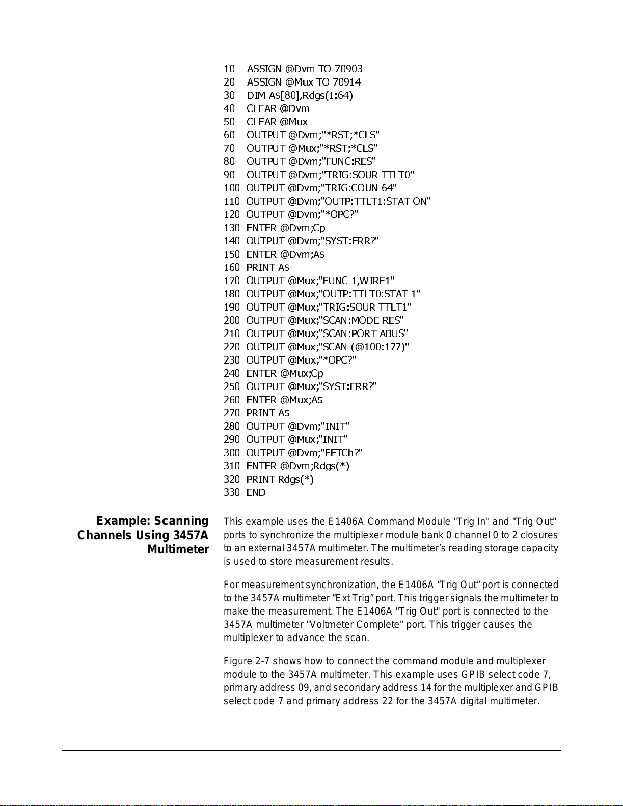
10 ASSIGN @Dvm TO 70903
20 ASSIGN @Mux TO 70914
30 DIM A$[80],Rdgs(1:64)
40 CLEAR @Dvm
50 CLEAR @Mux
60 OUTPUT @Dvm;"*RST;*CLS"
70 OUTPUT @Mux;"* RST;*CLS"
80 OUTPUT @Dvm;"FUNC:RES"
90 OUTPUT @Dvm ;"TRIG:SOUR TTLT0"
100 OUTPUT @Dvm;"TRIG:COUN 64"
110 OUTPUT @Dvm;"OUTP:TTLT1:STAT ON"
120 OUTPUT @Dvm;"*OPC?"
130 ENTER @Dvm;Cp
140 OUTPUT @Dvm;"SYST:ERR?"
150 ENTER @Dvm;A$
160 PRINT A$
170 OUTPUT @Mux ;"FUNC 1,WIRE1"
180 OUTPUT @Mux;"OUTP:TTLT0:STAT 1"
190 OUTPUT @Mux;"TRIG:SOUR TTLT1"
200 OUTPUT @Mux;"SCAN:MODE RES"
210 OUTPUT @Mux;"SCAN:PORT ABUS"
220 OUTPUT @Mux;"SCAN (@100:177)"
230 OUTPUT @Mux;"*OPC?"
240 ENTER @Mux;Cp
250 OUTPUT @Mux;"SYST:ERR?"
260 ENTER @Mux;A$
270 PRINT A$
280 OUTPUT @Dvm;"INIT"
290 OUTPUT @Mux;"INIT"
300 OUTPUT @Dvm;"FETCh?"
310 ENTER @Dvm;Rdgs(*)
320 PRINT Rdgs(*)
330 END
Example: Scanning
Channels Using 3457A
Multimeter
Chapter 2
This example us es the E1406A Command Module "Trig In" and "Trig Out"
ports to synchronize t he multiplexer module bank 0 channel 0 to 2 closures
to an external 3457A multimeter. The multimeter’s reading storage capacity
is used to store measurement results.
For measurement sy nc hronization, the E1406A “Trig Out ” port is connected
tothe 3457A multimeter “Ext Trig” port. This trigger signals the multimeter to
make the measurement. The E1 406A "Trig Out" port is connected to the
3457A multimeter "Voltmeter Complete" port. This trigger causes the
multiplexer to advance the scan.
Figure 2-7 shows how to connect the command module and multiplexer
module to t he 3457A multimeter. This example uses GPIB select cod e 7,
primaryaddress09, and seconda ry address 14 for the multiplexer and GPIB
select code 7 and primary add ress 22 for the 3457A digital multimeter.
Using the Relay Multiplexer 47
Page 48

Trig
Trig
Out
In
E1406A
Command
Module
E1460A
Multiplexer
HI
LOHI ILO
3457A Multimeter
Voltmeter
Complete
External
Trigger
+5V
0V
+5V
0V
Figure 2-7. Example: Scanning Channels Using 3457A Multimeter
10 OUTPUT 722;"TRIG EXT;DCV;MEM FIFO"
20 OUTPUT 70914;"*RST;*CLS"
30 OUTPUT 70914;"OUTP ON"
40 OUTPUT 70914;"TRIG:SOUR EXT"
50 OUTPUT 70914;"SCAN:MODE VOLT"
60 OUTPUT 70914;"SCAN (@10000:10015)"
70 OUTPUT 70914;"INIT"
(Rear View)
!Configures the 3457A multimeter to external
trigger to me as ure DCV and store readings
!Resets multiplexer module to a known state
!Enables E 1406A " Tri g Out" port
!Sets switc hbox trig ger source to external
triggering
!Sets switc hbox measurement mode
!Defines channel list
!Closes bank 0 channel 0 and enables the
scan. Causes a trigger output from E1406A
"Trig Out" port which initiates the external
multimeterto makea measurement . When the
measurement is complete, the multimeter’s
"VM Complete" port sends a trigger to the
multiplexer to advance the scan.
80 Wait 1
90 FOR Channels = 1 to 16
100 ENTER 722;Results
110 NEXT Channels
120 END
48 Using the Relay Multiplexer
!Wait 1 sec ond
!Start count ing loop (16 channe ls)
!Enter m eas urement result
!Increment count and repeat measurement
process for 16 measurements
!Terminate program
Chapter 2
Page 49

Example: Scanning
Multimeter DCV
Measurements
This ex ample uses the E1406A Comman d Module, E1411B System
Multimeter, and E1460A multiple xe r modules to perform a DC voltage
measurement on all 64 channels in a s c anning m ult im eter configuration.
In the scanning mu ltimeter configurat ion, the multiplexer module’s logica l
address must be set on e number higher than the multimeter module.
Figure 2-8 shows how to connect the multiplexer module to the multimeter
module. This ex ample us es GPIB select code 7, primary address 09, and
secondary address 03 for the scanning multimeter (multimeter/multiplexer).
SWITCH CARD TERMINAL MODULE
OPEN
CLOSE
OPEN
CLOSE
CH 0991
CH 0992
H1
L1
H
COM
L
H
CH 0
L
H
CH 1
L
H
CH 2
L
ANALOG BUS
TO MULTIMETER
Figure 2-8. Example: Scanning Multimeter DCV Measureme nts
10 DIM Rdgs(1:64)
20 OUTPUT 70903;"*RST"
30 OUTPUT 70903;"ROUT:FUNC1,WIRE2X64"
Command
Module Module
DC VOLTAGE #1
BANK 0
DC VOLTAGE #2
DC VOLTAGE #3
Voltmeter
Multiplexer
Module
!Dimension computer to store readings
!Reset the scanning m ultimeter m odule to a
known state
!Required to close controlrelay0995 to a ccess
upper 4 banks
Chapter 2
40 OUTPUT 70903;"MEAS:VOLT:DC? (@100:177)"
50 ENTER 70903;Rdgs(*)
60 FOR I = 1 TO 64
70 PRINT Rdgs(I)
80 NEXT I
90 END
!Configurethe scanning multimeter tomeasure
voltage on bank 0 channels 0 to 2
!Enter m eas urement result
!Start count ing loop (3 channels)
!Display m easurement result
!Increment the count and repeat measurement
process for a total of 3 measurements
!Terminate program
Using the Relay Multiplexer 49
Page 50

Example: Scanning
Multimeter Resistance
Measurements
This program uses an E1406A Comma nd Module to verify the E1460A
multiplexer will work in one-wire mode for resistance measurements with
the E1411B multimeter when t he two are instruments are configured as a
scanning multimeter.
For this example to work in either switchbox or scanning multimeter mode,
you mus t externally connect the HI current source banana jack to the HI
input ba nana jack and the LO current Source/COM to the LO input banana
jack on the front panel of the E1411B multimeter.
For this examp le, the following resistors are connected to the one-wire COM
terminal. The remain ing channels are open.
1kΩ on c hannel 00 HI
1.5 kΩ on channel 00 LO
1.2 kΩ on channel 01 HI
1.8 kΩ on channel 01 LO
A typical result returns
to the *IDN? command. Also,
and jumpers 11, 12, and 13 are in place, ROUT:FUNC? will return "WIRE1""
is displayed.
The f our channels with resistors conn ected return the nominal value of the
resistor, s uchas 1003. 129 f or c hannel 00 HI or 1489.102 for channel 00 LO.
All other channels return 9.9E+37 to indicate an open chann el.
10 DIM A$[40],Rdgs(1:66)
20 ASSIGN @Dvm TO 70903
30 OUTPUT @Dvm ;"*RST;*CLS"
40 WAIT 2
50 OUTPUT @Dvm ;"*IDN?"
60 ENTER @Dv m;A$
70 PRINT A$
80 OUTPUT @Dvm ;"ROUT:FUNC? 1"
90 ENTER @Dv m;A$
100 PRINT "If E1460A terminal module jumper 10 is cut, and jumpers 11"
110 PRINT "12, and 13 are in place, ROUT:FUNC? will return ’WIRE1’."
120 PRINT A$
130 OUTPUT @Dvm;"MEAS:RES? (@10000:10101)"
140 ENTER @Dvm;Rdgs(*)
150 PRINT Rdgs(*)
160 END
HEWLETT-PACKARD,E1411B,0,A.04.02
"If E1460A terminal module jumper 10 is cut
in res pons e
50 Using the Relay Multiplexer
Chapter 2
Page 51

Miscellaneous Multiplexer Functions
This section describes some m isc ellaneous multiplexer functions, including:
• Using the Scan Complete Bit
• Using the Analog Bus
• Sav ing and Recalling States
• Detecting Error Conditions
• Synchronizing the Multiplexer
Using the Scan
Complete Bit
Example: Using the Scan
Complete Bit
10 OUTPUT 70914;"*CLS"
20 OUTPUT 70914;"STAT:OPER:ENAB 256"
30 OUTPUT 70914;"*SRE 128"
The s c an co mplete bit (bit 8) can be used in the Operation Status Register
of a switchbox to determine when a scanning cycle compl etes (no other bits
in the register apply to th e switchbox). Bit 8 has a decimal value of 256 and
you can read it directly with the STAT:OPER? command.
When enabledby the STAT:OPER:ENAB 256 command, the scan complete
bit will b e reported as bit 7 of t he Status Byte Register. Use the GPIB Serial
Poll or the IEEE 488.2 Common Command *STB? to read the Status Byte
Register. When bit 7 of the Status Byte Register is enabled by the *SRE 128
common command to assert a GPI B Service Request, you can interrupt the
computer when t he scan complete bit is set, a fter the scanning cycle
completes. This allows the controller to do other operations while the
scanning cycle is in progress.
This example monitors bit 7 in the Status Byte Register to determine w hen
the scanning cycle completes. The example uses GPIB select code 7,
primary address 09, and secondary addre ss 14 for the multiplexer.
!Clear all switchbox status structure
!Enable scan complete bit to set bit 7 in
Status By t e Register
!Enable bit 7 of Status Byte Register to
assert RQS
Chapter 2
40 OUTPUT 70914;"TRIG:SOUR EXT"
50 OUTPUT 70914;"SCAN (@100:102)"
60 OUTPUT 70914;"INIT"
70 WHILE NOT BIT(SPOLL(70914),7)
80 PRINT "DO OTHER OPERATION HERE"
90 END WHILE
100 PRINT "INTERRUPT GENERATED"
110 END
!Set to extern al trigger mode
!Defines channel list to scan bank 0 channels
0 through 2
!Start scanning cycle
!Waiting for s can complete
!Enter program li nes for computer to do other
operations
!Program goes t o th is line after interrupt is
generated by a com pleted scanning cycle
!Terminate program
Using the Relay Multiplexer 51
Page 52

Using the Analog
Bus
The multiplexer can be configured to perform voltage, two-wire ohm, or
four-wire ohm measurements using the analog bus. T hes e measurements
can be performed by switching or scanning channe ls (refer to the previous
examples).
By s w itc hing the control relays (0990 to 0996), the COM lines can be
connected to the analog bus connection for measurement using a VXI
multimeter (such as the E1411B) or external multimeter (such as the
3457A). A special terminal enables the multiplexer to perform cable or
harness t es ting. You can connec t the multiplexer analog bus to other
measurement or switching devices to perform measurements.
During a scan, the control relays (0992 to 0994 and 0996) are automatically
switched when configured using the SCAN:PORT co mm and. See
[ROUTe:]SCAN:PORT on for more information.
When switching channels using the OPEN and CLOSe comm ands , the
analog bus must be manually connected. When the FUNCtion command is
executed, all analog bus control relays are opened. If an analog bus
connection is required, you m us t close the appropriate control relay. Once
switched, the relay remains c losed unless spec ifically opened (OPEN
command, power-up, or *RST). Control relay numbers and functions follow.
• 0992:Conn ec ts lower 32 channels (banks 0 to3)to the analog bus
H1 t ermi nals.
Example: Connecting the
Analog Bus
• 0993: Connects upper 32 channels (banks 4 to 7) to the analog
bus H2 terminals.
• 0994: Connects lower and upper analog buses together (64
channel).
• 0996: Connects analog bus Guard (G) to the LO line on the upper
32 channels (banks 4 to 7).
In this example , as shown in Figure 2-9, the HI and LO terminals of bank 0
channel 0 are c losed and the LO terminal of bank 4 channel 0 is closed
connecting t hem to their COM terminals. Control relays 0990 and 0991 are
automatically s et o pen when configured for three-wire mode.
To connect bank 0 (both terminals) and bank 4 (LO terminal to Guard) to the
analog bus, control relays 0992 and 0996 must be closed. To conn ec t bank
0 and bank 4 to the analog bus, execut e:
CLOS (@10992,10996)
!Close control relay 0992 to conn ec t bank
0-3 to the analog bus. Close control relay
0996 to connect bank 4-7 LO terminal to
the analog bus Guard te rminal
52 Using the Relay Multiplexer
Chapter 2
Page 53

SWITCH CARD TERMINAL MODULE
OPEN
CLOSE
OPEN
CLOSE
CH0992
CH0990
JM1
CH0991
CH0996
H
L
H
L
H1 H
H1 L
GUARD
H
L
H
L
COM
CH0
COM
CH0
ANALOG BUS
1IN
2IN
BANK 0
1OUT
2OUT
CABLE TEST
NO CONNECTION
3IN
NO CONNECTION
3OUT
BANK 4
Figure 2-9. E xample: Connecting th e Anal og Bus
Example: Cable Testing You can connect and test multi-conductor cables or wiring harness
conductors (for cont inui ty) and insulators (for short circuit) using a single
multiplexer module and system multimeter module.
Use the OP E N /CLOS < c hannel_list> commands to switch the c ontrol
relays. For example, to close control relay 0992 (connect banks 0-3 to
analog bus), execu te CLOS (@109 92).
The E1411B multimeter can directly measure channels of single or multiple
multiplexer modules in ascanning multimeter con fig uration. The multimet er,
when correctly programmed, automatically closes t he appropriate control
relays (09 90-0996). For more information, see the E1326B/E1411B User’s
Manual.
The cable tes t example that follows can be expanded to test cables with
more than 4 conductors. Continuity is checked by closing additi onal channel
relays to test the odd numbered wires on the first loop pas s , and the even
numbered wires on the sec ond loop pass (lines 60-180). Insulators are
checked in groups of four wires by adding an other loop (sim il ar to lines 210
to 420).
Chapter 2
Using the Relay Multiplexer 53
Page 54

For this exam ple, the multiplexer module is configured to test a 4-conductor
cable. Jumper JM1 must be removed to isolate the cable test terminal.
Jumpers JM2 and J M3 must b e removed to isolate bank 0 from bank 2.
Figure 2-10 shows how to conne ct the cable under test and the multimeter
to the multiplexer. This exa mpl e uses GPIB select cod e 7, primary address
09, and secondary address 03 for the multimeter and GPIB selec t code 7,
primary address 09, and secondary addre ss 14 for the multiplexer.
In the program , lines 10-30 set up multimeter for resistance measurement.
Lines 40-50 reset multiple xe r and switch banks 0-3 to analog bus. Lines
60-180 measure continuity of cable. T he first loop pass measures wires 1
and 3 and the second loop pa ss me as ures wires 2 and 4.
Lines 190-420 measure insulation (short-circuit) of cable. The firstloop pass
measures wires 1 to 3, 2 to3,2 to 4, 1 to 4, and 1 to 2. The second loop pass
measures wires 3 to 1, 4 to 1, 4 to 2, 3 to 2, and 3 to 4 .
SWITCH CARD
CH 0994
CH 0992
OPEN
CLOSE
CH 0990
OPEN
CLOSE
CH 0991
JM3JM2JM1
JM10 JM11
CH 0995
TERMINAL MODULE
H
BNK 0 CO M
L
BNK 0 CH 1H
BNK 0 CH 1L
BNK 0 CH 2H
BNK 0 CH 2L
BNK 2 COMH
BNK 2 COML
BNK 2 CH 1H
BNK 2 CH 1L
BNK 2 CH 2H
H1(1W HI COM)
L1(1W LO COM)
H1
L1
G
ANALOGBUS
H2
L2
G
BNK 2 CH 2L
CABLET
1W LO REF
TO EXTERNAL MULTIMETER
TOSYSTEM MULTIMETER
JM13JM12
H1
L1
G
H1
L1
G
H2
L2
G
H2
L2
G
CABLE UN DER TEST
WIRE 1
WIRE 2
WIRE 3
WIRE 4
USERWIRING
54 Using the Relay Multiplexer
Figure 2-10. Example: Cable Testing
Chapter 2
Page 55

10 OUTPUT 70903;"*RST"
20 OUTPUT 70903;"CONF:RES;*OPC?"
30 ENTER 70903;Opc_
40 OUTPUT 70914;"*RST"
50 OUTPUT 70914;"CLOS (@10992)"
60 FOR I =1 TO 2
70 OUTPUT 70914;"CLOS (@101,121);*OPC?"
80 ENTER 70914;Opc_
90 OUTPUT 70903;"READ?"
100 ENTER 70903;A(I)
110 OUTPUT 70914;"OPEN (@101,121)"
120 OUTPUT 70914;"CLOS (@102,122);*OPC?"
130 ENTER 70914;Opc_
140 OUTPUT 70903;"READ?"
150 ENTER 70903;B(I)
160 OUTPUT 70914;"OPEN (@102,122)"
170 OUTPUT 70914;"CLOS (@10990,10991)"
180 NEXT I
190 OUTPUT 70914;"OPEN (@10990,10991)"
200 OUTPUT 70914;"CLOS (@122)"
210 FOR I = 1 TO 2
220 J = I + 100
230 OUTPUT 70914;"CLOS @";J;")"
240 OUTPUT 70903;"READ?"
250 ENTER 70903;C(I)
260 OUTPUT 70914;"CLOS (@10990)"
270 OUTPUT 70903;"READ?"
280 ENTER 70903;D(I)
290 OUTPUT 70914;"CLOS (@10991)"
300 OUTPUT 70903;"READ?"
310 ENTER 70903;E(I)
320 OUTPUT 70914;"OPEN (@10990)"
330 OUTPUT 70903;"READ?"
340 ENTER 70903;F(I)
350 OUTPUT 70914;"OPEN (@121,122)"
360 K = I + 120
370 OUTPUT 70914;"CLOS (@";K;")"
380 OUTPUT 70903;"READ?"
390 ENTER 70903;G(I)
400 OUTPUT 70914;"OPEN (@10990,10991)"
410 OUTPUT 70914;"OPEN (@":J;")"
420 NEXT I
430 PRINT "Continuity Wire # 1/2/3/4=";A(1),A(2),B(1),B(2)
440 PRINT "Insulation Wire # 1 to 2/3/4=";G(1),C(1),F(1)
450 PRINT "Insulation Wire # 2 to 1/3/4=";G(1),D(1),E(1)
460 PRINT "Insulation Wire # 3 to 1/2/4=";C(2),F(2),G(2)
470 PRINT "Insu lation Wire # 4 to 1/2/3=";D(2),E(2),G(2)
480 END
Chapter 2
Using the Relay Multiplexer 55
Page 56

Saving and
Recalling States
NOTE *RCL, *RST, and *SAV do not affect the operating mode as set by the
The *SAV < num eric_s tate> command saves the current instrument state.
The s t ate number (0-9) is specified in the numeric_state parameter. The
following settings a re saved:
• Channel Relay States (bank 0-7 relays open or closed)
• Control Relay States (bank 9 relays open or closed)
• ARM:COUN t
• TRIGger:SOURce
• OUTPut[:STATe]
• INITiate:CONTinuous
• [ROUTe:]SCAN:MODE
• [ROUTe:]SCAN:PORT
The *RCL <numeric_s tate> command recal ls a previously saved state.
Enter the number (0-9) in the numeric_stateparameter of the des ired saved
state. If *SA V was not previous ly executed using the selec ted number, the
multiplexer module will conf igure to the reset values (refer to table 2-2).
FUNCtion comm and or status register switch positions. I f using the
FUNCtion command to set the operating mode, the *SAV/*RCL com mand
must be executed AFTER t he FUNCtion comm and.
Detecting Error
Conditions
Example: Error Checking
Using Polling
There are two general approaches to error checking: polling and using
interrupts. An example of each method follows.
The s im plest, but most time consuming, meth od is to ask the instrument
whetherthere are errorsat every step ofthe switching process. This is called
polling and is illustrated in the following example.
10 DIM Err_num$[256]
20 OUTPUT 70914;"CLOS (@101)"
30 OUTPUT 70914;"SYST:ERR?"
40 ENTER 70914;Err_num$
50 IF VAL (Err_num $ ) 0 THEN
60 PRINT "Error";Err_num$
70 STOP
80 END IF
90 ...(program continues)
56 Using the Relay Multiplexer
Chapter 2
Page 57

Example: Error Checking
Using Interrupts
The s ec ond approach to error checking involves the use of interrupts. The
following program is a method of checking f or errors using interrupts as you
program t he multiplexer. The program moni tors the multiplexer’s Standard
Event Status Register f or an error condition. See the E1406A Command
Module User’sManual fordetailed information on the Standard Event Status
Registers.
If no errors occur, the multiplexer functions as programmed. If errors do
occur, the multiplexer interrupts the comp uter and the error codes and
messages are read from the error queue. This example uses GPIB select
code 7, primary ad dress 09, and secondary addres s 14 for the multiplexer.
10 ON INTR 7 CALL Errmsg
20 ENABLE INTR 7:2
30 OUTPUT 70914;"*SRE 32"
40 OUTPUT 70914;"*ESE 64"
50 .
60 .
70 .
80 END
90 SUB Errmsg
100 DIM Message$[256]
120 CLEAR 70914
130 B = SPOLL (70914)
!Call computer subprogram "Errm sg " if a
multiplexer programming error occurs
!Enable the computer to respond to an
interrupt from the mul tiplexer
!Unmask the event status bit in th e
multiplexer’s Status Register
!Unmask the error conditions in multiplexer
Standard Event Status Regi s ter
!Program multiplexer for desired application
!Error Mess age subprogram
!When an error occurs , clear the multiplexer
to regai n con trol
!Execute a serial poll to clear the service
request bit in the Status Register
Chapter 2
140 REPEAT
150 OUTPUT 709 14;"SYST:ERR?"
160 ENTER 70914:Code,Message$
170 PRINT Code,Message$
180 UNTIL Cod e = 0
190 OUTPUT 70914;"*CLS"
200 STOP
210 SUBEND
!Read all error messages in the multiplexer
error qu eue
!Clear all bits in the multiplexer’s Standard
Event Status Register
Using the Relay Multiplexer 57
Page 58
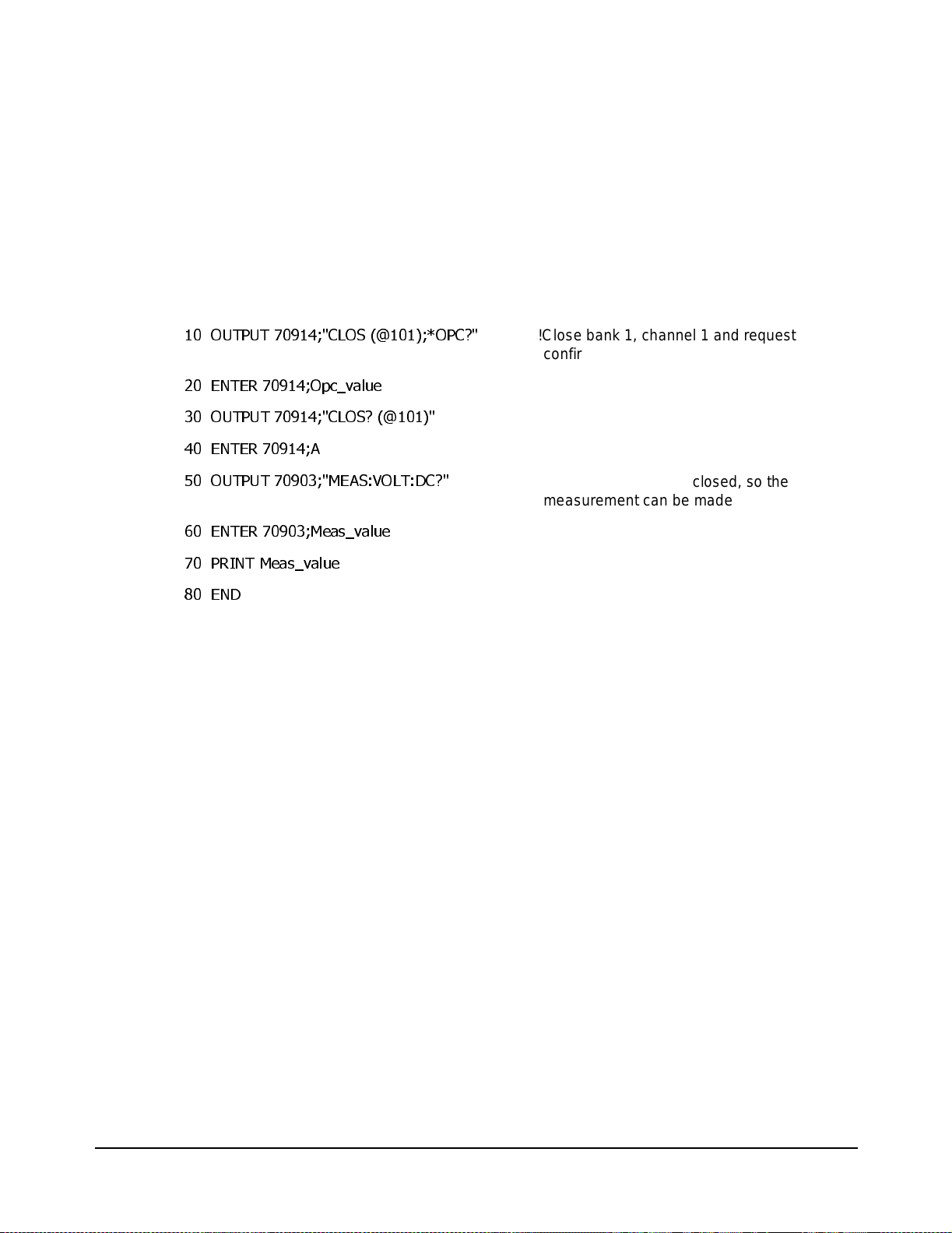
Synchronizing the
Multiplexer
This s ec ti on discusses sync hronizing the mul tiplexer module to other
instruments when making measurements.
Example: Synchronizing
Instruments
10 OUTPUT 70914;"CLOS (@101);*OPC?"
20 ENTER 70914;Opc_value
30 OUTPUT 70914;"CLOS? (@101)"
40 ENTER 70914;A
50 OUTPUT 70903;"MEAS:VOLT:DC?"
60 ENTER 70903;Meas_value
70 PRINT Meas_v alue
80 END
This example shows one way to synchronize instruments by switching a
signal t o be measured by a multimeter. This program verifies that the
switching is complete before the multim eter begi ns a measurement.
The example uses GP IB select code 7, primary address 09, and s ec ondary
address 03 for the multimeter and GP I B select c ode 7, primary addres s 09,
and secondary address 14 for the multiplexer.
!Close bank 1, channel 1 and request
confirmation that the channel is closed
!Read confirmation
!Channel is confirmed closed, so the
measurement can be made
58 Using the Relay Multiplexer
Chapter 2
Page 59

Relay Multiplexer Command Reference
About This Chapter
This chapter des cribes Standard Commands for Programmable
Instruments (SCPI) and IEEE 488.2 Common Commands for the
E1460A Relay Multiplexer module. See the appropriate command
module user’s manual for additional information on SCPI and Common
Commands. This chapter contains the following sections:
Command Types
Commands are separated into t w o types: IEEE 488.2 Common
commands and SCPI commands.
Chapter 3
• CommandTypes....................................59
• SCPICommandReference ...........................61
• IEEE488.2CommonCommandsQuickReference.........95
• SCPICommandsQuickReference .....................96
Common
Commands Format
SCPI Commands
Format
The IEE E 488.2 standard defines the Common commands that perform
functions like reset, self-test, status byte query, etc.Common commands
arefour or five characters inlength, always begin with anasterisk(*), and
may include one or more param eters. The command key w ord is
separated from t he fir st param eter by a space character. Some
examples of Common commands are:
*RST, *ESE <mask>, *STB?
SCPI commands perform functions like closing s w itc hes, mak ing
measurements, and querying instrument states or retrieving data.
A subsystem command structure is a hierarchical structure that usually
consists of a top-level (or root) command, one or more lower-level
commands, and their parameters. The following example shows part of
a typical subsystem:
[ROUTe:]
CLOSe <channel_list>
SCAN <channel_list>
:MODE?
[ROUTe:] is th e optional root comma nd, CLO Se an d SCAN are
second-level commands with parameters, and :MODE? is a third-level
command. [ROUTe:] is an implied command and is, therefo re, optional.
Chapter 3
Relay Multiplexer Command Reference 59
Page 60

Command Separator A colo n (:) always separates one command from the next lower-level
command, such as [ROUTe:]SCAN:MODE? Colons separate the root
command from the second-level command ([ROUTe:]SCAN) and the
second level from the third level (SCAN:MODE?).
Abbreviated Commands The command syntaxshows mo st commandsas a mix ture of upper- and
lowercase letters. The upperc as e letters indicate the abbreviated
spelling for the com mand. F or shorter program lines, send the
abbreviated form. For better program reada bility, you may send the
entire com mand. The instrument will accept either the abbreviated form
or the entire co mm and.
For ex ample, if the command syntax shows DIA Gnos tic, DIAG and
DIAGNOSTIC are both acceptable forms. Other forms of DIAGnostic,
such as DIAGN or DIAGNOS willgenerate an error.You m ay us e upperor lowerc as e letters. Therefore, DIAGN OS TI C, diagnos tic, and
DiAgNoStIc are all acceptab le.
Implied Commands Implied commands appear in square brackets ([ ]) in the c ommand
syntax.The brackets are not part of the command and are not sent to t he
instrument. Suppose you send a second-level comma nd but do notsend
the preceding im plied com mand. In this case, the instrument assumes
you intended to use the im plied command and it responds as if you had
sent it. Examine the portion of the [ROUTe] subsystem shown below:
Variable Commands
Syntax
[ROUTe:]
CLOSe? <channel_list>
The root com mand [ROUTe:] is an implied command. To make a query
about a channel’s pres ent status, you can send either of the following
command statements:
ROUT:CLOSe? <channel_list>orCLOSe?<channel_list>
Some commands have what appears to be a variable syntax, such as
OUTPut:ECLTrgn and OUTPut:TTLTrgn. In these co mm ands , the n is
replaced by a number. No space is left bet ween t he command and the
number because the number is not a parameter. The number is part of
the command syntax. In the case of OUTP:ECLTrgn, n canrangefrom
0to1.InOUTP:TTLTrgn, n can range from 0 through 7.
60 Relay Multipl exer Command Reference
Chapter 3
Page 61

Parameter Types The following table contains explanations and examples of parameter
types you may see in this chapter.
Type Explanations and Examples
Boolean
Discrete
Numeric
Optional
Boolean parameters represent a single binary condition
thatis eithertrue or false (ON, OFF,1, 0). Any non-zero
value is con sidered true.
Discrete parameters selects from a finite number of
values. These p arameters use mnem onics to represent
each val id setting. An example is TRIGger:SOURc e
<source>, where source can be BUS , EXTernal, HOLD,
IMMediate, ECLTrgn, or TTLTrgn.
Numericparameters are commonly used decimal
representations of numbers including optional signs,
decimal points, and scientific no tation (for example, 123,
123E2, -123, -1.23E2, .123, 1.23E -2, 1.23000E - 01).
Special c as es include MIN, MAX, DEFault, and INFinity.
Optional parameters are shown within square brackets
([]). The brackets are not part of the command and are
not sent to the instrument. If you do not specify a value
for an optional paramet er, the instrument choos es a
default value.
For examp le, consider ARM:COUNt? [MIN |MAX ]. If you
send the command wi tho ut specifying a parame ter, the
present A RM:COUNt value is returned. If you send the
MIN parameter, the c ommand ret urns the minimum
count av ail able. If you send the MAX parameter, the
command returns the maximum count available. P lace a
space between the command and t he parameter.
Linking Commands Linking IEEE 488.2 Common Commands with SCPI Com mands. Use a
semicolon (;) between the commands. For example, *RS T;*RCL 1 or
CLOS (@101);*SAV 1.
LinkingMultipleSCPI commands. Use both a semicolon (;) and a colon (:)
between the commands, such as CLOS (@101);:CLOS? (@101). SCPI
also allows several commands within the same subsystem to be linked
with a semicolon and colo n, such as
ROUT:CLOS (@101);:ROUT:CLOS? (@101).
SCPI Commands Reference
This s ec tion des cribes the Stand ard Comm ands for Programmable
Instruments (SCPI) for the Rel ay Multiplexer module . Commands are
listed alphabetically by subsystem and within each subsystem.
Chapter 3
Relay Multiplexer Command Reference 61
Page 62

ABORt
Subsystem Syntax ABORt
TheABORtcommand stops a scan inprogress when the scan isenabled
via the interface and the trigger s ource is TRIGger:SOURc e B US or
TRIGger:SOURce HOLD.
Comments ABORt Actions: The ABORt command terminates a scan in progress by
causing the sw itc hbox to no longer wait for a trig ger. Whe n the ABOR t
command is executed, the last channel switched during the scan
remains in the position.
Stopping Scan Enabled Via Interface: When a scan is enabled via an
interface,an interface c learcommand (CLEAR 7) can beused to stopthe
scan. When the scan i s enabled via the interface and TRIG:SOUR BUS
or HO LD is set, you can use ABORt to stop the scan.
Restarting a Scan: Use the INITiate command to restart the s c an.
Related Commands: ARM, INITiate:CONTinuous, [ROUTe:]SCAN,
TRIGger
Example Stopping a Scan with ABORt
This example stops a (continuous) two-wire scan in progress in a
single-module switchbox.
TRIG:SOUR BUS
INIT:CONT ON
SCAN (@100:107)
INIT
.
.
.
ABOR
!Trigger command w ill be via backplane
(bus) i nterface (*TRG command
generates trigger)
!Set continuous sc anning
!Scan channels 0 to 7 in bank 0
!Start sc an, close channel 0
!Abort scan in progress
62 Relay Multipl exer Command Reference
Chapter 3
Page 63

ARM
Subsystem Syntax ARM
ARM:COUNt
Parameters
The ARM subsystem selectsthe number of scanning cycles (1 to 32767)
for each INITiate command.
:COUNt <number>MIN I MAX
:COUNt?[MIN | MAX]
ARM:COUNt <number> MIN | MAX allows scanning cycles to occur a
multiple of times (1 to 32,767) with one INITiate command when
INITiate:CONTinuous OFF | 0 is set. MIN sets 1 cycle and MAX sets
32,767 cycles.
Name Type Range of Values Default
<number> numeric 1 thru 32,767 I MIN I MAX 1
Comments Number of Scans: Use only numeric values between 1 and 32767, MIN,
or MA X for the number of scanning cycles.
Related Commands: ABORt, INITiate:IMMediate
*RST Condition: ARM: COUNt 1
Example Setting Ten Scanning Cycles
This ex ample s ets a multiplexer mod ule for 10 scans of channels 0
through 7 i n bank 1 in a single-module switchbox.
ARM:COUN 10
SCAN (@110:117)
INIT
!10 sc ans per INIT command
!Scan channels 0 to 7 in bank 1
!Start sc an, close channel 0
Chapter 3
Relay Multiplexer Command Reference 63
Page 64

ARM:COUNt?
Parameters
ARM:COUNt? [MIN I MAX] returns the current number of scanning cycles
setby ARM:COUNt. T he current numberof scan cycles is returned when
MIN or MAX is not specified. With MIN or MAX as a parameter, MIN
returns 1 and MAX returns 32,767.
Name Type Range of Values Default
<MIN | MAX> numeric MIN = 1, MAX = 32,767 current
cycles
Comments
Related Commands: INITiate[:IMMediate]
Example Query Number of Scans
This ex ample s ets a multiplexer mod ule for 10 scanning cycles and
queries th e numb er of scan cycles set. The ARM:COUN? command
returns 10.
ARM:COUN 10
ARM:COUN?
!Set 10 scans per INIT command
!Query number of scans
64 Relay Multipl exer Command Reference
Chapter 3
Page 65

INITiate
Subsystem Syntax INITiate
INITiate:CONTinous
Parameters
The I NIT iate command s ubsystem selects continuous scanning cycles
and starts the scanning cy cle.
:CONTinuous <mode>
:CONTinuous?
[:IMMediate]
INITiate:CONTinuous <mode> enables or disables continuous scanning
cycles.
Name Type Range of Values Default
<mode> boolean 0 I 1 I OFF I ON OFF I 0
Comments Continuous Scanning Operation: Continuous sc anning is enabled with
the INITiate:CONTinuous ON or INITiate:CONTinuous 1 command.
Sending the INITiate:IMMediate command close s the f irst channel in the
channel list. Each trigger from the source specified by the
TRIGger:SOURce command advances thescan through the channe l list.
A trigger at the end of the channel list closes the first channel in the
channel list and the scan cycle repea ts.
Non-Continuous Scanning Operation: Non-continuous scanning is
enabled with the INITiate:CONTinuous O FF or INITiate:CONTinuous 0
command. Sending the INITiate:IMMediate comman d close s the first
channel in the channel list. Each trigger from the source specified by the
TRIGger:SOURce command advances thescan through the channe l list.
At the end of the scanning cycle, the last channel in the channel list is
closed and the scanning cycle s tops.
Stopping Continuous Scan: See the ABORt command .
Related Commands: ABORt, ARM:COUNt, TRIGger
*RST Condition: INITiate:CONTinuous OFF | 0
Chapter 3
Relay Multiplexer Command Reference 65
Page 66

Example Enabling Continuous Scanning
This ex ample enables continuous sc anning of bank 3, chann els 0
through 7o f a switchbox. Since TRIGger:S OURc e IMMediate (defa ult) is
set,the example uses an interface clearcommand (CLEAR 7)to stop the
scan.
INITiate:CONTinuous?
Example Query Continuous Scanning State
INIT:CONT ON
SCAN (@130:137)
INIT
.
CLEAR 7
INITiate:CONTinuous? queries the sc anning stat e. With continuous
scanning enabled, the command returns "1" (ON). With continuous
scanning disabled, the command returns "0" (OFF).
This ex ample enables continuous sc anning of a switchb ox and que ries
the st ate. Since continuous scanning is enabled, INIT:CONT? returns
"1".
INIT:CONT ON
INIT:CONT?
!Enable continuous scanning
!Scan channels 0 to 7 in bank 3
!Start sc an, close channel 0
!Stop scan cycle
!Enable continuous scanning
!Query continuous s c anning state
INITiate[:IMMediate]
INITiate[:IMMediate] starts the scanning process and closes the first
channel inthe channellist. Successive triggers from the source specified
by the TRIGger:SOURce command advance the scan through the
channel list.
Comments Starting the Scanning Cycle: The INITiate:IMMediate command starts
scanning by closing the first channel in the channel list. Each trigger
received advances the scan to the next ch annel in the channel list.
An i nvalid channel list definition causes an error (see [ROUTe:]SCAN).
Stopping Scanning Cycl es: See the ABORt command.
66 Relay Multipl exer Command Reference
Chapter 3
Page 67

Example Enabling a Single Scan
This example enables a single scan of channels 0 through 7 in bank 5 of
a single-module s witc hbox . The trigger source to advance the scan is
immediate (internal) triggering set with TRIGger:SOURce IMMediate
(default).
SCAN (@150:157)
INIT
!Scan channels 0 to 7 in bank 5
!Begin scan, close channel 0 (use
immediate triggering)
Chapter 3
Relay Multiplexer Command Reference 67
Page 68

OUTPut
The OUTPut command subsystem selects the source of the output
trigger generated when a channel is closed during a scan. The selected
output c an be enabled, disabled, and queried. The three available
outputs are the ECLTrg, TTLTrg trigger buses as well as the command
module’s (E1406A) front panel "Trig Out" port.
Subsystem Syntax OUTPut
OUTPut:ECLTrgn[:STATe]
:ECLTrgn< (:ECLTrg0 or ECLT rg1)
[:STATe] <mode>
[:STATe]?
[:EXTernal]
[:STATe] <mode>
[:STATe]?
:TTLTrgn (:TTLTrg0 through :TTLTrg7)
[:STATe] <mode>
[:STATe]?
Parameters
Comments
OUTPut:ECLTrgn[:STATe] <mode> selects and enables which ECL
Trigger bus line (0 or 1) will output a trigger when a channel is closed
during a sca n. This is also used to disable a selected ECL Trigger bus
line. "n" specifies the ECL Trigger bus line (0 or 1) and "mode" e nables
(ON or 1) or disables (OFF or 0) the specified ECLTrg bus line.
Name Type Range of Values Default
<n>numeric 0or1 N/A
<mode> boolean 0 I 1 I OFF I ON OFF I 0
Enabling ECL Trigger Bus: When enabled, a pulse is output f r om the
selected ECL Trigger bus line (0 or1)after each channel is closed during
a scan. If disabled, a pulse is not output. T he output is a negative-going
pulse.
ECL Trigger Bus Line Shared by Switchboxes: Only one switchbox
configuration can use the se lecte d trigger at a time. When enabled, the
selected E C L Tri gger bus line (0 or 1) is pulsed by the sw itc hbox each
time a s ca nned c hannel is closed. To disable the outp ut for a specific
switchbox, send the OUTPut:ECLTrgn OFF or 0 command for that
switchbox.
68 Relay Multipl exer Command Reference
Chapter 3
Page 69

One Output Selected at a Ti me: Only one output (ECLT rg0 or 1; TTLTrg0,
1, 2, 3, 4, 5, 6, or 7; or EXTernal) can be enabled at one time. Enabling
a different outp ut source will automatically disable the active output.
For example, i f TTLTrg1 is the active output, and TTLTrg4 is enabled,
TTLTrg1 will become disabled and TTLTrg4 wil l become the active
output.
Related Commands: [ROUTe:]SCAN, TRIGger:SOURce,
OUTPut:ECLTrgn[:STATe]?
*RST Condition: OUTPut:ECLTrgn[:STATe] OFF (disabled)
Example Enabling ECL Trigger Bus Line 0
OUTP:ECLT0:STAT 1
OUTPut:ECLTrgn[:STATe]?
OUTPut:ECLTrgn[:STATe]? q ueries thepresentstate ofthe specifiedECL
Trigger bus line. The command returns "1" if the specified bus line is
enabled or " 0" if the specified bus line is disabled.
Example Query ECL Trigger Bus Enable State
This example enables ECL Trigger b us line 0 and queries the enable
state. The OUTPut:ECL Trgn? command returns "1" since the port is
enabled.
OUTP:ECLT0:STAT 1
OUTP:ECLT0?
OUTPut[:EXTernal][:STATe]
!Enable ECL Trigger bus line 0 to output
pulse after each s can ned c hannel is
closed
!Enable ECL Trigger bus line 0
!Query bus enable state
Chapter 3
OUTPut[:EXTernal][:STATe] <mode> enables or disables the "Trig Out"
porton the E1406A Command Module to output a trigger when a channel
is c losed during a scan. ON I 1 enables the port and OFF | 0 disables the
port.
Parameters
Name Type Range of Values Default
<mode> boolean 0 I 1 I OFF I ON OFF I 0
Relay Multiplexer Command Reference 69
Page 70

Comments Enabling “Trig Out” Port: When enabl ed, a pulse is output from the “Trig
Out” port after each s canned swit ch box channel is closed. If disabled, a
pulse is not output from the port after channel closures. The output is a
negative-going pulse.
“TrigOut” Port Shared by Switchboxes:Only one switchbox configuration
can use the selected trigger at a time. When enabled, the “Trig Out” port
is p ulsed by the switchbox each time a scanned channel is closed. To
disable t he output for a specific switchbox, sen d the OUTP OF F or 0
command for that s w itchbox.
One Output Selected at a Ti me: Only one output (ECLT rg0 or 1; TTLTrg0,
1, 2, 3, 4, 5, 6, or 7; or EXTernal) can be enabled at one time. Enabling
a different outp ut source will automatically disable the active output.
For example, i f TTLTrg1 is the active output and TTLTrg4 is enabled,
TTLTrg1 will become disabled and TTLTrg4 wil l become the active
output.
Related Commands: [ROUTe:]SCAN, TRIGger:SOURce,
OUTPut[:EXTernal][:STATe]?
*RST Condition: O U TPut[:EXTernal][:STATe] OFF (disabled)
Example Enabling "Trig Out" Port
OUTP:EXT 1
OUTPut[:EXTernal][:STATe]?
OUTPut[:EXTernal][:STATe]? queries the present state of the "Trig Out"
port. The command returns "1 " if the port is enabled or "0" i f disabled.
Example Query "Trig Out " Port Enable State
This ex ample enables the "Trig Out" port and queries the enable state.
The OUTPut? command returns " 1" since the port is enabled.
OUTP:EXT ON
OUTP:EXT?
OUTPut:TTLTrgn[:STATe]
OUTPut:TTLTrgn[:STATe] <mode> selects and enables which TTL
Trigger bus line (0 to 7) will output a t rigger when a channel is closed
during a sca n. This is also used to disable a selected TTL Trigger bus
line. "n" specifies the TTL Trigger bus line (0 to 7) and "mode" enables
(ON or 1) or disables (OF F or 0) the specified TTL Trigger bus line.
!Enable "Trig Out" port to output pulse
after each scanned channel is closed
!Enable “Trig Out” port
!Query port enabl e state
70 Relay Multipl exer Command Reference
Chapter 3
Page 71

Parameters
Name Type Range of Values Default
<n>numeric 0or7 N/A
<mode> boolean 0 I 1 I OFF I ON OFF I 0
Comments Enabling TTL Trigger Bus: When enabled, a negative-go ing pulse is
output from the selected T TL Trigger bus line (0 to 7) after each channel
inthe switchbox is closed during a scan. If disabled, a pulse is not output.
TTL Trigger Bus Line Shared by Switchboxes: Only one switchbox
configuration can use the se lectedTT L Trigger at a time. When enabled,
the selected TTLTriggerbus li ne (0 to 7) is pulsed by the switchbox eac h
time a s ca nned c hannel is closed. To disable the outp ut for a specific
switchbox, send the OUTPut:TTLTrgn OFF or 0 command for that
switchbox.
One Output Selected at a Ti me: Only one output (ECLT rg0 or 1; TTLTrg0,
1, 2, 3, 4, 5, 6>, or 7; or EXTernal) can be enabled at one time. Enabling
a different outp ut source will automatically disable the active output.
For example, i f TTLTrg1 is the active output and TTLTrg4 is enabled,
TTLTrg1 will become disabled and TTLTrg4 wil l be the active output.
Related Commands: [ROUTe:]SCAN, TRIGger:SOURce,
OUTPut:TTLTrgn[:STATe]?
*RST Condition: OUTPut:TTLTrgn[:STATe] OFF (disabled)
Example Enabling TTL Trigger Bus Line 7
OUTP:TTLT7:STAT 1
OUTPut:TTLTrgn[:STATe]?
OUTPut:TTLTrgn[:STATe]?queries the present state of the specified TTL
Trigger bus line. The command returns "1" if the specified TTLTrg bus
line is enabl ed or "0" if disabled.
Example Query TTL Trigger Bus Enable State
This ex ample enables TTL Tri gger bus line 7 and queries the enable
state. The OUTPut:TTLTrgn? command returns "1" since the port i s
enabled.
!Enable TTL Trigger bus line 7 to output
pulse after each s can ned c hannel is
closed
Chapter 3
OUTP:TTLT7:STAT 1
OUTP:TTLT7?
!Enable TTL Trigger bus line 7
!Query bus enable state
Relay Multiplexer Command Reference 71
Page 72

[ROUTe:]
Subsystem Syntax [ROUTe:]
The [ROUTe:] command subsystem controls switching and scanning
operations for multiplexer modules in a switchbox.
NOTE This c ommand opens a ll previously closed relays. Therefore, it should be
the first relay configuration command.
CLOSe <channel_list>>
CLOSe? <channel_list>
FUNCtion card_number,<func tion>
FUNCtion? <card_number >
OPEN <channel_list>
OPEN? <channel_list>
SCAN <channel_list>
:MODE <mode>
:MODE?
:PORT <port>
:PORT?
[ROUTe:]CLOSe
Parameters
Comments One-Wire Mode (WIRE1): When closing a channel in one-wire m ode, the
[ROUTe:]CLOSe<channel_list>closes the multiplexer channelsspecified
by channel_list. Channel_list has the f orm (@ss 0hbc) w here ss =card
number (01-99), 0h = one-wire mode only high/low switching (00 or 01),
b = bank nu mber (0-7), and c = channel number (0-7).
Name Type Range of Values Default
<channel_list> numeric ss[00]00 to ss0177
ss00 to ss77
ss00 to ss037
ss00 to ss037
HIor LO linemustbe selected using channel_list. 01 selects HI, and 00
selects LO. If one-wire mode is se lected,and a four-digitchannel number
is used, the LO line is selected.
Two-Wire Mode (WIRE2/WIRE2X64): Switches the HI and LO t erminals of
a channel in banks 0 through 3 or banks 4 through 7 to that bank’s HI
COM and LO COM terminals.
1-wire
2-wire
3-wire
4-wire
72 Relay Multipl exer Command Reference
Chapter 3
Page 73

• WIRE2: Configures the E1460A as two independent 2x32
multiplexers.
• WIRE2X64: Switches the HI and LO terminals of a channel in banks
0 through 7 to that bank’s HI COM and LO COM terminals.
A m ax im um of 64 two-wire channels can be switched. This mode is
available via E1406A (S witc hbox R ev. A06.00 or later). Prior to this
revision, closin g control relay 0995 in two-wire mode will change the
card configuration to a single 64-channel two-wire multiplexer.
Three/Four-Wire Modes (WIRE3/WIRE4): When closing a channel in
three-wire or four-wire modes, only the lower bank (0-3) is specified.
The upper bank pair (4-7) will automatically close the specified channel.
If an attempt is made to close the upper bank pair (4-7) channels, an
error wi ll be generated.
Closing Channels: To close:
• a single channel, use ROUT:CLOS (@ssbc)or(@ss0hbc)
• multiple channel s , use ROUT:CLOS (@ssbc,ssbc,...) or
(@ss0hbc,ss0hbc,...)
• sequent ial channels, use ROUT:CLOS (@ssbc:ssbc)or
(@ss0hbc:ss0hbc)
• groups of sequential channels, use ROUT:CLOS (@ssbc:ssbc,
ssbc:ssbc)or(@ss0hbc:ss0hbc, ss0hbc:ss0hbc)
• or any combination of the above
NOTE Channel numbers can be in the chann el_list in any random order.
However, closure order for multiple channels with a sin gle command is
not guaranteed.
Closing the Control Relays: The c ontro l relays (0990 to 0996) can be
closed to perform special functions (for example, connec tingchannels to
the analog bus). Chan nels must be chang ed after the multiplexer has
been configured using the [ROUTe:]FUNCt ion command. Close:
• 0990 to select the LO terminal for one-wire switching
• 0991 to connect one-wire LO REF terminal to the one-wire
LO COM terminal
• 0992 to connect lower 32 channels (banks 0 to 3) to the analog bus
• 0993 to connect upper 32 channels (banks 4 to 7) to the analog bus
• 0994 to connect lower and upper analog buses together
• 0995 to connec t lower and upper c ommon buses together (64-channel
two-wire operation)
• 0996 to connect analog bus Guard to the LO line on the upper 32
channels (banks 4 to 7)
*OPC? Command: Using the *OPC? command after the CLOSe
command in your programs will ensure t hat the channel CLOSe
command has executed prior to performing the next function (measure,
read, etc .). This programmi ng practice is highly recommen ded.
Chapter 3
Relay Multiplexer Command Reference 73
Page 74

Related Commands: [ROUTe:]OPEN, C LOSe?, SCAN
*RST Condition: All multipl ex er channels are open.
Example Closing Multiplexer Channels
This example closes channel 0, bank 0, in card 0 1, and channel 7, bank
6, in card 02 of a two-module switchbox. Both modules are in t wo-wire
mode.
[ROUTe:]CLOSe?
Comments Queryi s Software Readback: T he ROUTe:CLOSe? command ret urns the
CLOS (@100,267)
[ROUTe:]CLOSe? <channel_list> returns the current state of the
channel(s) queried. Channel_list has the form (@ssbc)or(@ss0hbc)
(see [ROUTe:]CLOSe f or definition). The command returns "1" if
channel(s) are closed or returns "0" if channel(s) are open.
current software state of the channel(s) specified. It does not account for
relay hardware failures. A maximum of 128 channels at a time can be
queried f or a multiple-module switchbox.
Three/Four-Wire Modes (WIRE3/WIRE4): When configured for three- or
four-wire mo des, the upper bank pair (4-7) channels cannot be queried.
If an attem pt is made to query the upper bank pair (4-7) channels, an
error wi ll be generated.
!100 closes channel 0 , bank 0 of card #1
and 267 closes channel 7, bank 6 of
card #2
Example Query Channel Closure
This example closes channel 0, bank 0, in card 0 1, and channel 7, bank
6, in card 02 of a two-module switchbox and queries channel closure.
Since the channels are programmed to be closed "1,1" is returned.
CLOS (@100,267)
CLOS? (@100,267)
74 Relay Multipl exer Command Reference
!100 closes channel 0, b ank 0 , card #1 and
267 closes channel 7, bank 6, card #2
!Query state of c hannel 0, bank 0, card #1
and channel 7, bank 6, card #2
Chapter 3
Page 75

[ROUTe:]FUNCtion
Parameters
[ROUTe:]FUNCtion <card_number>, <function> selects the operating
mode of the multiplexer channels. All channels on the card specified by
card_number operate in the s pec ified m ode. [ROUTe:] is NOT optional
when ROUT:FUNC is used with a scanning multimeter configuration.
Name Type Range of Values Default
<card_number> numeric 01 to 99 N/A
<function> discrete WIRE1IWIRE2|
WIRE 2X64 I
WIRE 3 I WIRE 4
WIRE 2
Comments ROUTe is Not Always Optional: If used with a scanning multimeter
configuration, ROUTe:FUNCtion must be used.
Command Not Always Used: This comm and is not required if the status
register sw itc h is configured to the desired mode.
Using the FUNCtion Command: When usingthe FUNCtion command to
reconfigure the multiplexer to a diff erent operating mode t han the status
register sw itc h is set to, the command must be sent
powered up.
One-Wire Mode (WIRE1): Switches either the HI or LO terminal of a
channel in banks 0 through 7, to the one-wire HI COM or one-wire LO
COM terminal. When closing a c hannel in one-wire mode, the HI or LO
line m ust be selected using channel_list. Only one of the 128 one-wire
channels can be switched at a time.
Two-Wire Mode (WIRE2): Switches both the HI and LO terminals of a
channel in banks 0 through 3 or banks 4 through 7 to that bank’sHI COM
and LO COM terminals.
AFTER the card is
Chapter 3
Two-Wire Mode (WIRE2X64): Switches the HI and LO terminals of a
channel in banks 0 through 7 to that bank’s HI COM and LO COM
terminals. A max im um of 64 two-wire channels can be switched. This
mode is available via E1406A (Switchbox Rev. A06.00 or later). Prior to
this revision, closing c ontrol relay 0995 in two-wire mode will change the
card configuration to a single 64-channel two-wire multiplexer.
Three-Wire Mode (WIRE3): Banks are paired 0/4, 1/5, 2/6, and 3/ 7.
Switches both the HI an d LO terminal of a channel in bank 0-3, to that
bank’s HI and LO COM termin als. Also switches the LO terminal of t he
channel in pair bank 4-7 to that bank’s LO COM terminal.
Relay Multiplexer Command Reference 75
Page 76

When closing a channel in three-wire mode, only the lower bank (0-3) is
specified and the upper bank pair (4-7) will automatically close. A
maximum of 32three-wire channels can be switched. Selecting an upper
bank (4-7) channel ca us es an error.
NOTE In three-wire mode, do not connect user wiring to the HI terminal in the
upper bank pair (4-7). This terminal is switched during three-wire operation,
and dependent on relay configurations, could be switched to
the HI C OM terminal.
Four-Wire Mode (WIRE4): Banks are paired 0/4, 1/5, 2/6, and 3/7.
Switches both the HI an d LO terminal of a channel in bank 0-3, to that
bank’s HI COM and LO COM terminals. Also switches the HI and LO
terminal of the chan nel in pair bank 4-7, to that bank’s HI and LO COM
terminals.When closing a channel infour-wire mode, only the lowerbank
(0-3) is specified, and the upper bank pair (4-7) will automatically close.
A m ax im um of 32 four-wire channels can be switched. Selecting an
upper bank (4-7) channel ca us es an error.
Related Commands: [ROUTe:]OPEN, [RO UTe:]CLOSe, [ROUTe:]SCAN
*RST: *RST d oes no t change the selec ted mode.
Example Configuring Multiplexer Mode
[ROUTe:]FUNCtion?
Example Query Operating Mode
This example configures card 01 of a single-module switchbox to
four-wire m ode.
FUNC 1,WIRE4
[ROUTe:]FUNCtion? <card_number> returns the current operating mod e
of the card(s) queried. See [ROUTe:]FUNCtion for card_number
definition. The com mand returns "WIRE1" if in the one-wire mod e,
"WIRE2" if in the two-wire mode, "WIRE3" if in the three-wi re mode, or
"WIRE4" if in the four-wire mode.
This example set s card #1 in a single-module switchbox to one-wire
mode and queries the operating state . Since the one-wire mode is
selected, "WIRE1" is returned.
FUNC 1,WIRE1
FUNC? 1
!Configures card #1 to four-wire mode
!Configure card #1 to one-wire mode
!Query m ode of card #1
76 Relay Multipl exer Command Reference
Chapter 3
Page 77

[ROUTe:]OPEN
Parameters
[ROUTe:]OPEN <channel_list> opens the multiplexer channels specified
by channel_list. Channel_list has the f orm (@ss 0hbc) w here ss =card
number (00-99), 0h = one-wire mode only high/low switching (00 or 01),
b = bank nu mber (0-7), and c = channel number (0-7).
Name Type Range of Values Default
<channel_list> numeric ss[00]00 to ss0177
ss00 to ss77
ss00 to ss037
ss00 to ss037
1-wire
2-wire
3-wire
4-wire
Comments One-WireMode (WIRE1): When opening a channel in one-wire mode, the
HI or LO line must be selected using channel_list. 01 selects HI and 00
selects LO. If one-wire mode is se lected,and a four-digitchannel number
is used, the LO line is selected.
Two-Wire Mode (WIRE2): Switches both the HI and LO terminals of a
channel in banks 0 through 3 or banks 4 through 7 to that bank’sHI COM
and LO COM terminals
Two-Wire Mode (WIRE2X64): Switches the HI and LO terminals of a
channel in banks 0 through 7 to that bank’s HI COM and LO COM
terminals. A max im um of 64 two-wire channels can be switched. This
mode is available via E1406A (Switchbox Rev. A06.00 or later). Prior to
this revision, closing c ontrol relay 0995 in two-wire mode will change the
card configuration to a single 64-channel two-wire multiplexer.
Three/Four-Wire Modes (WIRE3/WIRE4): When opening a channel in
three-wire or f our-wire m odes , only the lower bank (0-3) is specified. The
upper bank pair (4-7) will automatically open the specified channel. If an
attempt is made to open the upper bank pair (4-7) channels, an error will
be generated.
Chapter 3
Opening Channels: To open:
• a single channel, use ROUT:OPEN (@ssbc)or(@ss0hbc)
• multiple channel s , use ROUT:OPEN (@ssbc,ssbc,...) or
(@ss0hbc,ss0hbc,...)
• sequent ial channels, use ROUT:OPEN (@ssbc:ssbc)or
(@ss0hbc:ss0hbc)
• groups of sequential channels, use ROUT:OPEN (@ssbc:ssbc,
ssbc:ssbc)or(@ss0hbc:ss0hbc, ss0hbc:ss0hbc)
• or any combination of the above
Relay Multiplexer Command Reference 77
Page 78

NOTE Channel numbers can be in the chann el_list in any random order. Hovever,
opening order for mul tip le channels with a single command is not
guaranteed.
Opening t he Control Relays: The control relays (0990 to 0996) can be
opened to perform special functions (for example, isolating channels
from the analog bus). Chann els must be changed after the multiplexer
has been configured using the [ROUTe:]FUNCtion comm and. Open:
• 0990 to select t he HI terminal for one-wire switching
• 0991 to connect Cable Test terminal to the one-wire LO COM terminal
• 0992 to disconnect lower 32 channels (banks 0 to 3) fro m the analog
bus
• 0993 to disconnect upper 32 channels (banks 4 to 7) from the analog
bus
• 0994 to disconnect lower and upper analog buses
• 0995 to disconnect lower and upper common buses (dual 32-channel
two-wire operation)
• 0996 to disconnect analog bus Guard from the LO line on the upper
32 channels (banks 4 to 7)
*OPC?Command: Using the *OPC? command after the OPEN command
in y our programs will ensure that the channel OPEN command has
executed prior to performing thenextfunc tion (measure, read, etc.).This
programming practice is highly r ec ommended.
RelatedCommands: ROUT e:]CLOS e, [ROUTe:]OPEN?, [ROUTe:]SCAN
*RST Condition: All multipl ex er channels are open.
Example Opening Multiplexer Channels
This ex ample opens channel 0, bank 0, in card #1 and channel 7, bank
6, in card #2 of a two-module switchbox. Both modules are in t wo-wire
mode.
OPEN (@100,267)
!100 opens channel 0, bank 0 of card #1
and 267 opens channel 7, bank 6 of
card #2
78 Relay Multipl exer Command Reference
Chapter 3
Page 79

[ROUTe:]OPEN?
Comments Query is Software Readback: TheROUTe:OPEN?commandreturnsthe
Example Query Channel Open State
[ROUTe:]OPEN?<channel_list>returnsthe current s t ate of thechannel(s)
queried. Channel_list has the form (@ssbc)or(@ss0hbc)(see
[ROUTe:]OPEN for definition). The command returns "1" if channel(s)
are open or returns "0" if channel(s) are closed.
current software state of the channel(s) specified. It does not account for
relay hardware failures. A maximum of 128 channels at a time can be
queried f or a multiple-module switchbox.
Three/Four-Wire Modes (WIRE3/WIRE4): When configured for three- or
four-wire mo des, the upper bank pair (4-7) channels cannot be queried.
If an attem pt is made to query the upper bank pair (4-7) channels, an
error wi ll be generated.
This ex ample opens channel 0, bank 0, in card #1 and channel 7, bank
6, in card #2 of a two-module switchbox and queries the channel open
states. S ince th e chan nels are programm ed to be opened "1 ,1" is
returned.
[ROUTe:]SCAN
Parameters
OPEN (@100,267)
OPEN? (@100,267)
[ROUTe:]SCAN <channel_list> defines the channels to be scanned .
Channel_list has the form (@ss0hbc) where ss = card number (00-99),
0h = one-wire mode only high/low switc hing (00 or 01), b = bank number
(0-7), and c = channel number (0-7).
Name Type Range of Values Default
<channel_list> numeric ss[00]00 to ss0177
!100 opens channel 0, bank 0,card #1 and
267 opens channel 7, bank 6, card #2
!Query state of c hannel 0, bank 0, card #1
and channel 7, bank 6, card #2
1-wire
ss00 to ss77
ss00 to ss037
ss00 to ss037
2-wire
3-wire
4-wire
Chapter 3
Relay Multiplexer Command Reference 79
Page 80

Comment Defining Scan List: When ROUTe:SCAN is executed, the c hannel list is
checked for val id card, terminal, bank, and channe l numbers. An error is
generated for an invalid channel list.
64 Channel Li mit: Individual c hannel numbers are limited to 64 due to the
maximum length of c ommand in the current driver.
Scanning Channels: To scan:
• a single channel, use ROUT:SCAN (@ssbc)or(@ss0hbc)
• mu ltiple channels, use ROUT:SCAN (@ssbc,ssbc,...) or
(@ss0hbc,ss0hbc,...)
• sequent ial channels, use ROUT:SCAN (@ssbc:ssbc)or
(@ss0hbc:ss0hbc)
• groups of sequential channels, use ROUT:SCAN (@ssbc:ssbc,
ssbc:ssbc)or<(@ss0hbc:ss0hbc, ss0hbc:ss0hbc)
• or any combination of the above
NOTE Channel numbers can be in the chann el_list in any random order.
Scanning Operation: When a valid channel list is defined,
INITiate[:IMMediate] begins the scan and closes the first channel in the
channel_list. Successive triggers from the source s pec ified by
TRIGger:SOURce advance the scan through the channel list.
Example Scanning Using External Devices
[ROUTe:]SCAN:MODE
Parameters
Stopping Scan: S ee the ABORt command.
Related Commands: OUTPut, TR IGger
*RST Condition: All channels open.
See "S canning Channels" in Chapter 2 for exampl es of scanning
programs us ing external instrum ents.
[ROUTe:]SCAN:MODE <mode> sets the m ultiplexer channels define d by
the [ROUTe:]SCAN <channel_list> command fo r none, volts, two-wire
ohms, or four-wire ohm s measurements.
Name Type Range of Values Default
<mode> discrete NONE I VOLT I RES I FRES NONE
80 Relay Multipl exer Command Reference
Chapter 3
Page 81

Comments Order of Command Execution: The [ROUTe:]SCAN:MODE and
[ROUTe:]FUNCtion commands m ust be executed before the
[ROUTe:]SCAN <channel_list> c ommand.
ROUTe:]SCAN:MODE versus [ROUTe:]FUNCtion:FRES: Meas urement
[
mode is not supported when FUNCtion is set to WIRE1 (one-wi re m ode).
NONE and VOLT Mode: When s elect ed, channel_list is setup for volts
measurements. VOLT mode is also used when making two-wire ohms
measurements using two-wire multimeters.
RES Mode: When selected, channel_list is setup for two-wire ohms
measurements. Control relay 0994 is closed when SCAN:PORT ABUS
is selected. When selected, the mu ltimeter SENSE/SOURCE leads are
used to make the m eas urement. When us ing the H I/LO lead s on a
multimeter to make the measurement, use t he VOLT m ode.
FRES Mode: When selected, channel_list is setup for four-wire ohms
measurements. When using four-wire ohms measurement mode, only
the lower bank (0-3) is specified with the [ROUTe:]SCAN <channel _list>
command. The upper bank pair (4-7) will aut omatically sel ec t the
specified channel. Selecting an upper bank (4-7) channel causes an
error.
*RST Condition: [ROUTe:]SCAN:MODE NONE
Example Selecting Four-Wire Ohms Measurements
This example selects four-wire ohms measurement mode (FRES) on
card # 1 of a single-module switchbox.
FUNC 1,WIRE4
TRIG:SOUR EXT
SCAN:MODE FRES
SCAN (@130:137)
INIT
!Set mode t o four-wire
!Selects external t r igger sourc e
!Selects four-wire W scan mode
!Scan channels 0 to 7 in bank 3 (paired
with channels 0 to 7 in bank 7)
!Starts s canning cy cle
Chapter 3
Relay Multiplexer Command Reference 81
Page 82

[ROUTe:]SCAN:MODE?
Comments Values Returned. The command returns NONE, VOLT, RES, o r FRES if
Example Query the Scanning Mode
[ROUTe:]SCAN:MODE? returns the current state of the s c an mode .
the scan mo de is in the none, volts, two-wire ohms, or four-wire ohms
measurement mode, respectively.
Thisexample selects thefour-w ire ohms measurement mode (FRES) on
card #1 of a single-module switchbox, then queries the measurement
state. Bec aus e fo ur-w ire ohms mode is selected, the query command
returns "FRES".
[ROUTe:]SCAN:PORT
Parameters
Comments Order of Command Execution: Measurement modes are selected by the
SCAN:MODE FRES
SCAN:MODE?
[ROUTe:]SCAN:PORT <port> en ables or disables the closin g of the
analog bus connection control relays 0992, 099 3, and 0996 during
scanning. SCAN:PORT ABUS closes the appropriate control relay for
analog bus connections. The ROUTe:SCAN:PORT NONE comman d
prevents closing t he c ontrol relays.
Name Type Range of Values Default
<port> discrete ABUS | NONE NONE
[ROUTe:]FUNCtion and [ROUTe:]SCA N:MODE c ommands. Then the
[ROUTe:]SCAN:PORT command, followed by the [ROUTe:]SCAN
<channel_list>command.
!Select four-wire oh ms scanning m ode
!Query t he s ca nning m ode
Analog Bus Connection: The SCAN:PORT ABUS command only
connects/disconnects the analog bus during scans. To connect/
disconnect the analog bus when not scanning channels, it is necessary
to switch the appropriate control relays (0992, 0993, and 0996). See the
[ROUTe:]CLOSe or [ROUTe:]OPEN for more information.
*RST Condition: [ROUTe:]SCAN:PORT NONE
82 Relay Multipl exer Command Reference
Chapter 3
Page 83

Example Selecting the Analog Bus Port
Thisexample selects thefour-w ire ohms measurement mode (FRES) on
card #1 of a single-module switchbox and then enables the analog bus
connection. Control relays 0992/0993 close and 0990/0991/0994/0995
open.
[ROUTe:]SCAN:PORT?
Example Query the Scan Port
FUNC 1,WIRE4
TRIG:SOUR EXT
SCAN:MODE FRES
SCAN:PORT ABUS
SCAN (@130:137)
INIT
[ROUTe:]SCAN:PORT? returns the current state of the analog bus port .
The command returns NONE i f the analog bus connection control relays
are disabled or ABUS if the control relays are enabled.
This ex ample selects the analog bu s port and then queries the state.
Because the analog bus port is selected, the query command returns
"ABUS".
SCAN:PORT ABUS
SCAN:PORT?
!Set mode t o four-wire
!Select external trigge r source
!Select the four-wire ohm s mode
!Select the analog bus port
!Scan channels 0-7 in bank 3 (pa ired
with channels 0-7, bank 7)
!Start scanning cycle
!Select the analog bus port
!Query the port sele ction
Chapter 3
Relay Multiplexer Command Reference 83
Page 84

STATus
Subsystem Syntax STATus
The STA Tus subsystem reports the bit values of the Operation Status
Register.It also allows y ou to unmask the bits you want reported from the
Standard E v ent Re giste r and to read the summary bits from the Status
Byte Regist er.
:OPERation
:CONDition?
:ENABle <number>
:ENABle?
[:EVENt?]
:PRESet
The S TATussystem contains four registers, two ofwhichare under IEEE
488.2 control: the S tandard E vent Status Registe r (*ESE?) and the
Status Byte Register (*STB?). The o perat ional status bit (O PR), service
request bit (RQS), standard event summa ry bit (ESB), message
available bit (MAV) and questionable data bit (QUE) in the Status Byte
Register(bi ts 7, 6, 5, 4 and 3 respectively)can be queried with the *STB?
command.
Use the *E SE? c omm and t o query the “unmask” value for the Standard
Event Status Register (the bits you want logically OR’d in to the sum mary
bit). The registers are queried using decimal weighted bit values. The
decimal equivalents for bits 0 through 15 are included in Figure 3-1.
A num eric v alue of 256 executed in a STAT:OP ER:ENABle <number>
command allows only bit 8 to ge nerate a summ ary b it. The decimal value
for bit 8 is 256.
The dec im al values are also used in the inverse manner to determine
which bits are set from the total value returned by an EVENt or
CONDition query. The multiplexer driver exploits only bit 8 o f Operation
Status Register. This bit is called the scan complete bit which is set
whenever a scan operation completes. S ince c ompletion of a scan
operation is an event in time, bit 8 will never appear set w hen
STAT:OPER:COND? is queried. However, you can find bit 8 set with the
STAT:OPER:EVEN? query command.
84 Relay Multipl exer Command Reference
Chapter 3
Page 85

Automatically Set at
Power On Conditions
Automatically Set by
RelatedCommands
are *OPC? and *WAI
Parser
Set by *OPC
Output Queue
Standard Event Register
PowerOn
User Request
Command Error
Execution Error
Device Dependent Error
Query Error
Request Control
Operation Complete
0
1
2
3
4
5
6
7
EV EN
Operation Status Register
STATus:OPERation:CONDition?
STATus:OPERation:EVENt?
STATus:OPERation:ENABle
*ESR?
<1>
<2>
<4>
<8>
<16>
<32>
<64>
<128>
*ESE <unmask>
*ESE?
"OR"
Summary
NOTE:
QUE = Questionable Data
MAV = M essage Available
ESB = StandardEvent
RQS = Request Service
OPR= Operation Status
C = ConditionRegister
EV = Event Register
EN = Enable Register
SRQ= InterfaceBus
ServiceRequest
Status Byte Register
*STB?
SPOLL
+
Bit
MAV
ESB
RQS
OPR
0
1
2
3
4
5
6
7
Status
Byte
Summary Bit
<1>
<2>
<4>
<8>
<16>
<32>
<128>
EN
*SRE < unmask>
*SRE?
"OR"
SRQ
+
System
Controller
Interface Bus
SRQ Line
SRQ
Other
Instrument
SRQ
Other
Instrument
ScanComplete
0
1
2
3
4
5
6
7
8
9
10
11
12
13
14
15
CEV EN
<1>
<2>
<4>
<8>
<16>
<32>
<64>
<128>
<256>
<512>
<1024>
<2048>
<4096>
<8192>
<16384>
<32768>
Figure 3-1. Relay Multiplexer Status System Registers
"OR"
+
Summary
Bit
unmask examples:
Register
Operation Complete
*ESE 61 unmasks standard event register bits 0,
2, 3, 4 and 5 (*ESE 128 only unmasks bit 7).
*SRE 128 unmasks the OPR bit (operation) in
the status byte register. This is effective
only if the STAT:OPER:ENAB 256 command
is ex ecuted.
STAT:QUES:ENAB256 unmasks the "Scan Complete"
bit.
unmask
decimal
bit
weight
<128>7
"OR"
ESB
+
Chapter 3
Relay Multiplexer Command Reference 85
Page 86

STATus:OPERation:CONDition?
STATus:OPERation:CONDition? returns the st ate of the Condition
Register in the Operation Status Group. The state represents conditions
which are part of the instrument’s operation. The mul tiplexer driver does
not set b it 8 in this register (see STATus:OPERation[:EVENt]?).
STATus:OPERation:ENABle
STATus:OPERation:ENABle <number> sets an enable mask to allow
events recorded in the Ev ent Register to send a summary bit to the
Status By te Registe r (bit 7). For multiplexer modules, when bit 8 in the
Operation Status Register is set t o 1 and that bit is enabled by the
STATus:OPERation:ENABlecommand, bit 7 inthe Status Register is set
to 1.
Parameters
Name Type Range of Values Default
<number> numeric 1 through 65,535 N/A
Comments SettingBit 7 of theStatus Register: STATus:O PERat ion:ENABle 256 s ets
bit 7 of the Status Register to 1 after bit 8 of the Operation Status
Register i s set to 1.
Related Commands: [ROUTe:]SCAN
Example Enabling the Status Register
STAT:OPER:ENAB 256
STATus:OPERation:ENABle?
STATus:OPERation:ENABle? returns which bits in the Event Register
(Operation Status Group) are unmasked.
!Enables bit 8 of the Operation Status
Register to be reported to bit 7 (OPR)
in th e Status Register
86 Relay Multipl exer Command Reference
Chapter 3
Page 87

STATus:OPERation[:EVENt]?
STATus:OPERation[:EVENt]? returns w hich bits in the Event Register
(Operation Status Group) are set. The Event Register indicat es wh en
there has been a time-related instrument event.
Comments Setting Bit 8 of the Operation Status Register: Bit 8 (scan complete) is set
to 1 after a scanning cycle completes. Bit 8 returns to 0 (zero) after
sending the STATus:OPERation[:EVENt]? command.
ReturnedDataafter Sending STATus:OPERation[:EVENt]?:The command
returns “ +256” if bit 8 of the Operation Status Register is set to 1. The
command returns “+0” if bit 8 of the Operation Statu s Register is s et to 0.
Event Register Cleared: Reading the Event Register with the
STATus:OPERation:EVEN t? command c lears it.
Aborting a scan: Aborting a scan will leave bit 8 set to 0.
Related Commands: [ROUTe:]SCAN
Example Reading the Operation Status Register After a Scanning Cycle
STATus:PRESet
STAT:OPER?
read the register value
STATus:PRESet affects only the Enable Register by setting all Enable
Register bits to 0. It does not affect either the "status byte" or the
"standard event status". PRESet does not clear any of the Event
Registers.
!Returns the bi t values of the Standard
Operation Status Register
!+256 shows bit 8 is set to 1 and +0
shows bit 8 is set to 0.
Chapter 3
Relay Multiplexer Command Reference 87
Page 88

SYSTem
TheSYSTem subsystemreturns the numbersandmessages in the error
queue of a switchbox , and returns the switchbox modul e des criptio ns .
Subsystem Syntax SYSTem
SYSTem:CDEScription?
SYSTem:CDEScription? <number> returns the module description.
Parameters
:CDEScription? <number>
:CPON <number>|ALL
:CTYPe? <num ber >
:ERRor?
Name Type Range of Values Default
<number> numeric 1 through 99 N/A
Comments Multiplexer Module Description: The SYSTem:CDEScription?command
returns the following E1460A des criptions, depending on mode currently
configured:
• One-Wire Mode: "128 Channel S.E. Relay Mux"
• Two-Wire Mode: "Dual 32 Channel 2-W ire Relay Mux"
• Two-Wire 64 Mode: "64 Cha nnel 2-Wire Relay Mux"
• Three-Wire Mode: "32 Channel 3-Wire Relay Mux"
• Four-Wire Mode: "32 Channel 4-W ire Relay Mux"
Example Reading the Description of a Card #1 Module
This example select s the one-wire mode, then queries the description.
Because one-wire mode is selected, the query command returns
"WIRE1".
FUNC 1,WIRE1
SYST:CDES?
!Set mode to one-wire
!Return the description
88 Relay Multipl exer Command Reference
Chapter 3
Page 89

SYSTem:CPON
Parameters
SYSTem:CPON <number> |ALLsets the selected module (card) in a
switchbox to its power-on state , with the exception of th e mode sele cted.
Name Type Range of Values Default
<number> numeric 1 through 99 N/A
Comments
Example Setting Card # 1 Module to its Power-on St ate
SYSTem:CTYPe?
Parameters
Multiplexer Module Power-on State: The power-on state is all c hannels
(relays) open. Note that SYSTem:C PON AL L and *RST opens all
channels ofallmodules in a switchbox, while SYSTem:CPON<number>
opens the channels in only the module (card) specifie d in the command.
Current operating mode (as set by FUNCtion command) will not be
affected by ex ec ution of the SYSTem:CPON <number>or*RST
commands.
SYST:CPON 1
SYSTem:CTYPe? <number> ret urns the module (card) type of a selected
module in a switchbox.
Name Type Range of Values Default
<number> numeric 1 through 99 N/A
!Set card #1 to its power-on state
Chapter 3
Comments
64-Channel Multiplexer Module Model Number: The SYSTem:CTYPe?
<number> command returns
where the 0 after E1460A is the module serial number (always 0) and
A.02.00 is an e xample o f the module revision code nu mber.
HEWLETT-PACKARD,El460A,0,A.02.00
Example Reading the Model Number of a Card #1 Module
SYST:CTYP? 1
!Returns the m odel number
Relay Multiplexer Command Reference 89
Page 90

SYSTem:ERRor?
Comments Error Numbers/Messages in the Error Queue: Each error generated by a
SYSTem:ERRor? returns the error numbers and corresponding error
messages in the error queue of a switchbox. See Appendix C for a listing
of swit c hbox e r ror numbers and messages.
switchbox s tores an error number and corresponding error message in
the error queue. The error message can be up to 255 characters long.
Clearingthe Error Queue: An error number/message is removed from the
queue each time the SYSTem:ERRor?command is sent. The errorsare
cleared fi rst-in, first-out. When the queue is empty, each following
SYSTem:ERRor? command returns +0, “No error”. To clear all error
numbers/messages in the queue, execute the *CLS command.
Maximum Error Numbers/Messagesin the Error Queue: The queue holds
a maximum of 30 error nu mbers/messages for each switchbox. If the
queue ov erflow s, the last error number/me ssage in the queueis replaced
by -350, “Too many errors”. The least recent error numbers/messages
remain in the que ue and the most recent are discarded.
*RST Condition: * R ST does n ot clear the error queue.
90 Relay Multipl exer Command Reference
Chapter 3
Page 91

TRIGger
Subsystem Syntax TRIGger
TRIGger[:IMMediate]
Comments Executing the TRIGger[:IMMediate] Command: First, the measurem ent
The TRIGger com mand subsystem controls the triggerin g operation of
multiplexer modules in a switchbox.
[:IMMediate]
:SLOPe <slope>
:SLOPe?
:SOURce <source>
:SOURce?
TRIGger[:IMMediate] ca use s a trigger event to occur when the defined
trigger sou rce is TRIGger:SOURce BU S or TRIGger:SOURc e HOLD.
modes m ust be selected using the [ROUTe:]FUNCtion and
[ROUTe:]SCAN:MODE commands. Then [ROUTe:]SCAN:PORT is
selected,followed by the [ROUTe:]SCAN <channel_list> command and
anINITiate[ :IMMediate]command.All must be executed(unless defaults
are used) before TRIGg er[:IMM ediate] will execute.
BUS or HOLD Source: If selected, the TRIGger:SOURce BUS or
TRIGger:SOURce HOLD commands remai n in effect after triggering a
switchbox with the TRIGger[:IMMediate] command.
Related Commands: INITiate, [ROUTe:]SCAN
Example Advancing Scan Using TRIGger Command
This ex ample us es the TRIGger command to advance the scan of a
single-module switchbox from bank 0, channels 0 through 7. Since
TRIGger:SOURce HOLD is set, t he scan is adv anced one channel each
time TRIGger i s executed. For the examp le, ROUTe:S C AN:MODE and
ROUTe:SCAN:PORT default values of NONE are used.
TRIG:SOUR HOLD
SCAN (@100:107)
INIT
loop statement
TRIG
increment loop
!Set trigger source to HOLD
!Scan channels 0 to 7 in bank 0
!Begin scan, close channel 00
!Start count loop
!Advance scan to next channel
!Increment loop count
Chapter 3
Relay Multiplexer Command Reference 91
Page 92

TRIGger:SLOPe
Parameters
TRIGger:SLOPe<slope> is used to s electthe polarity of the output trigger.
For the E1460A, this command is not used.
Name Type Range of Values Default
<slope>discrete NEG NEG
Comments
TRIGger:SLOPe?
Example Query Trigger Slope
TRIGger:SOURce
Parameters
Command Not Supported. Attempting t o chan ge the TRIGg er:SLOP e to
anything other than NE G will generate an error.
TRIGger:SLOPe?isused to querythe polarity of t he output trigger.Forthe
E1460A, this query alw ay s returns NEG.
TRIG:SLOP?
TRIGger:SOURce <source> specifies the trigger source to advance the
channel list during sc anning.
Name Type Range of Values Default
!Always returns NEG
BUS discrete *TRG or GET command IMM
ECLTrgn numeric ECL Trigger bus line 0 or 1 IMM
EXTernal discrete "Trig In" port IMM
HOLD discrete Hold Triggering IMM
IMMediate discrete Immediate Triggering IMM
Trgn numeric TTL Trigger bus line 0 - 7 IMM
Comments
92 Relay Multipl exer Command Reference
Enabling the Trigger Source: The TRIGger:S OURc e c omm and only
selects the trigger source. The INITia te[:IM Mediate] command enables
the trigger source.
Chapter 3
Page 93

Using the TRIGger Command: You can use TRIGger[:IMMediate] to
advance the scan when TRIGg er:SOURce BUS> or TRIGger:SOURce
HOLD is selected.
One Trigger Input Selected at a Time: Only one input (ECLTrg0 or 1;
TTLTrg0, 1, 2, 3, 4, 5, 6, or 7; or EXTernal) can be se lecte d at one time.
Enabling a different trigger source will automatically disable the active
input. For example, if TTLTrg1 is the active input, and TTLTrg4 is
enabled, TTLTrg1 will become disabled and TTLTrg4 will become the
active input.
Using External Trigger Inputs: With TRIGger:SOURce EXTernal
selected, only one switchbox at a time can use the external trigger input
at the E14 06A “Trig In” port. The trigger input is as signed to the first
switchbox that requ es ted the external trigger source (with an
TRIGger:SOURce EXTernal command).
Using TTL or ECL Trigger Bus Inputs: With TRIGger:SOURce TTLTrgn or
ECLTrgn selected, only one switchbox at a time can use the trigger bus
selected on the E1406A Command Module bus. The trigger input is
assigned to the first switchbox that requested the trigger source (with a
TRIGger:SOURce TTLTrgn or ECLTrgn command). Only one of the ten
available trigger bus lines (ECL0 to 1 or TTL0 to 7) can be specified at
one time.
Assigning EXTernal I TTLTrg I ECLTrg Trigger Source: A switchbo x
assigned with TRIGger:SOURce EXT | TTLT | ECLT remains assigned
to that source until the switchbox trigger source is changed to BUS,
HOLD, or IMMediate. When the source is changed, the trigger source is
available to the next switchbox that requests it (with a TRIGger:SOURce
ECLTn command). If a s witchbox requests a trigger already assigned to
another switchbox, an error is generated.
UsingBusTriggers: To triggerthe switchbox withTRIGger: SO URce BUS
selected, use the I EEE 488. 2 common c ommand *TRG or the GPIB
Group Execute Trigger (GET) command.
“Trig Out” Port Shared by Switchboxes: See the OUTPut com mand.
Related Commands: ABORt, [ROUTe:]SCAN, OUTP ut
*RST Condition: TR I Gger:SO URc e IMM ediate
Example Scanning Using External Triggers
This ex ample uses external triggering (TRIG:SOUR EXT) to scan bank
0,channels 0 through 7 of a single-modu le switchb ox . The trigger source
to advance the scan is the input to the " Trig In" on an E1406A Command
Module. When INIT is executed, the sc an is started and bank 0, channel
0 is closed. Then, each trigger received at the "Trig In" port advances the
scan to the next channel. For the example, ROUTe :SCAN:MODE and
ROUTe:SCAN:PORT default values of NONE are used.
Chapter 3
Relay Multiplexer Command Reference 93
Page 94

TRIG:SOUR EXT
SCAN (@100:107)
INIT
trigger externally
Example Scanning Using Bus Triggers
This example uses bus triggering (TRIG:SOUR BUS) to scan bank 0,
channels 0 through7 of a single-module switchbox. The trigger source to
advance the scan is the *TRG command (as set with TRIGger:SOURce
BUS). When INIT is executed, the scan is s tarted and bank 0, channel 0
is cl ose d. Th en, each *TR G co mm and adv ances the scan to the next
channel. For th e example, ROUTe: SCAN: MODE and
ROUTe:SCAN:PORT default values of NONE are used.
!Select external triggering
!Scan channels 0 to 7 in bank 0
!Begin scan, close bank 0, channel 0
!Advance scan to next channel
TRIGger:SOURce?
Example Querying the Trigger Source
TRIG:SOUR BUS
SCAN (@100:107)
INIT
loop statement
*TRG
increment loop
TRIGger:SOURce? returns the current trigger source f or the switchbox.
Command returns BUS, ECLT, EXT, HOLD, IMM, or TTLT for sourc es
BUS, ECLTrgn, EX Ternal, HOLD, IMMedia te, or TTLTrgn, respectiv ely.
This ex ample set s external triggering and queries the trigger source.
Since external triggerin g is set, TRIG:SOUR? returns "EXT".
TRIG:SOUR EXT
TRIG:SOUR?
!Trigger command w ill be via backplane
(bus) i nterface (*TRG command
generates trigger)
!Scan channels 0 to 7 in bank 0
!Begin scan, close bank 0, channel 0
!Loop to s c an all channels
!Advance scan using bus triggering
!Increment loop count
!Set external trigger source
!Query trigger source
94 Relay Multipl exer Command Reference
Chapter 3
Page 95

IEEE 488.2 Common Commands Reference
The following table lists the IEEE 488.2 C omm on ( *) Commands that
apply to the E1460A Relay Multiplexer module. For more information on
Common Commands, see the applicable command module user’s
manual or the A NS I/IEEE St andard 488. 2-1987.
Command Title Description
*
CLS
*ESE
*ESE?
*ESR
*IDN?
*OPC
*OPC?
*RCL
*RST
*SAV
<mask>
?
Clear Status Register Clearsall StatusR egisters, t he Request for OPC flag, and all Queues
(except output queue).
Event Status Enable Sets the bits in the Standard Event StatusEnable Register
Event Status Enable Query Queries the current contents in the Standard Event Status Enable
Register.
Event Status Register Query Queries and clears current contents in the Standard Event Status
Register.
Identification Query Returns I dentification String of the switchbox.
Operation Complete Sets the Request for OPC flag when all pending operations have
completed.Also sets OPC bit in the Standard Event Status Register.
Operation Complete Query Returnsa "1" t o the output queue when all pending operations have
completed.Ensures synchronization between multiple instruments.
Recall Saved State Recalls previously stored multiplexerconfiguration. <n>(0to9)is
location in memory where the desired (previously stored) set-up is
located.
Reset Opens all channels and invalidates current channel list for scanning.
Sets ARM:COUN 1, TRIG:SOUR IMM, INIT:CONT OFF,
OUTP:STATOFF,SCAN:MODE NONE, and SCAN:PORT NONE
Save Current State Stores the current multiplexerconfiguration i n memory. Stores
current settings of the channel states.<n>(0to9)isthelocation
in memory where the current set-up is to be stored.
*SRE
<mask>
*SRE?
*STB?
*TRG
*TST?
*WAI
Chapter 3
Service Request Enable Sets the Service Request Enable Register bits and corresponding
Serial Poll Status Register bits to generate a service request. Enable
an event by specifying its decimal weight for ma sk.
Service Byte Enable Query Queries current contents in the Service Request Enable Register.
Status Byte Query Queries the current contents in the Status Byte Register.
Trigger When scan is enable and trigger source to TRIG:SOUR BUS, use
*TRG to trigger the switchbox to advance the scan.
Self-Test Query ( cc = card
number with leading 0
deleted)
Wait to Continue Halts execution of commands and queries until No Operation
Returns+0ifselftestpasses.
Returns +cc01 for firmware error.
Returns +cc02 for bus error (communication problem with card).
Returns +cc03 for bad ID information (ID Register on card).
Returns +cc10 if an interrupt was expected but not received.
Returns +cc11 if the busy bit was not held ~9 to 17 msec.
Pending message is true.
Relay Multiplexer Command Reference 95
Page 96

SCPI Commands Quick Reference
The following table summarizes SCPI comm ands for the E1460A Relay
Multiplexer module.
Command Description
ABORt
ARM :COUNt <
:COUNT? [MIN | MAX]
INITiate :CONTinuous ON I OFF I 1 | 0
:CONTinuous?
[:IMMediate]
OUTPut :ECLTrgn[:STATe] ON | OFF 1| 0
:ECLTrgn[:STATe]?
[:EXTernal][:STATe] ON I OFF 1 I 0
[:EXTernal][:STATe]?
:TTLTrgn[:STATe]ON I OFF I 1 I 0
:TTLTrgn[:STATe]?
[ROUTe:] CLOSe <
CLOSe? <
FUNCtion
FUNCtion? <
OPEN <
OPEN? <
SCAN <
SCAN:MODE <
SCAN:MODE?
SCAN:PORT <
SCAN:PORT?
number
channel_list
channel_list>
<card_number
channel_list
channel_list
channel_list
> MIN | MAX
card_number
mode
port
>
>
>,<
function
>
>
>
>
>
Abort a scan in progress
Multiple scans per INIT command
Query number of scans
Enables/Disables continuous scanning
Query c ontinuous scan state
Starts a scanning cycle
Enables/Disables ECL Trigger bus line pulse
Query ECL Trigger bus line state
Enables/Disables "Trig Out" pulse
Query port enable state
Enables/Disables TTL Trigger bus line pulse
Query TTL Trigger bus line state
Close channel(s)
Query channel(s)
>
Set operating mode
Query operating mode
Open channel(s)
Query channel(s)
Define channels for scanning
Set scan mode
Query scan mode
Select Analog Bus
Query Analog Bus state
STATus :OPERation:CONDition?
:OPERation:ENABle <
:OPERation:ENABle?
:OPERation[:EVENt]?
:PRESet
SYSTem :CDEScription? <
:CPON <
:CTYPe? <
:ERRor?
TRIGger [:IMMediate]
:SLOPe <
:SLOPe?
:SOURce BUS
:SOURce ECLTrg
:SOURce EXTernal
:SOURce HOLD
:SOURce IMMediate
:SOURce TTLTrg
:SOURce?
number
number
slope
number
> I ALL
>
>
n
n
number
>
>
Returns status of Condition register
Enables events in t he Event register to be reported
Returns which bits in the Event register are unmasked
Returns which bits in the Event register are set
Sets Enable register bits to 0
Returns description of module in switchbox
Sets specified module in a switchbox to its power-on state
Returns the module type
Returns error number/message to error queue
Causes a trigger to occur
Select negative polarity of the out put trigger
Query polarity of the output trigger
Triggersource is *TRG
Triggersource is ECL Triggerbus line 0 or 1
Triggersource is "Trig In" port
Hold off triggering
Continuous (internal) triggering
Triggersource is TTL Trigger bus line (0 - 7)
Query current t rigger source
96 Relay Multipl exer Command Reference
Chapter 3
Page 97

Input Characteristics
Appendix A
Relay Multiplexer Specifications
Maximum Voltage Terminal to Terminal:
220 Vdc; 250 Vac
Maximum Current per Channel (non-inductive):
1 Adc or ac
0.3 Adc or ac
Bias Current:
From HI or LO t o chassis, per group of 16 channels:
<0.5 nA/Volt(at 25
DC Performance
Insulation Resistance (between any two points):
6
>5x10
Ω at 40°C, 95% RH
8
>5x10
Ω at 25°C, 40% RH
Maximum Thermal Offset per Channel:
µV (differential H-L)
<7
AC Performance
Minimum Bandwidth (-3dB, 50 W source/load):
2-Wire m ode (4x16): >10 MHz
1-Wire m ode (1x128): >3 MHz
Open Channel Capacitance
(channel to channel, channel to common):
2-Wire m ode (4x16): <30 pF
1-Wire m ode (1x128): <380 pF
rms
(Vmax<30Vdcor250V
rms
(Vmax<133Vdcor150V
rms
0
C, 25% RH)
rms
)
rms
)
Maximum Voltage Terminal to Chassis:
220 Vdc; 250 Vac
Maximum Power per Channel:
rms
40VA
Closed Channel Resistance:
<1.5
Ω initially
Ω at end of relay life
<3.5
Crosstalk Between Channels @10 kHz:
2-Wire mode (4x16): <-90 dB
1-Wire mode (1x128): <-60 dB
Closed Channel Capacitance (Hi-Lo, Lo-Chassis):
2-Wire mode (4x16): 650/700 pF
General
Module Size / Device Type:
C-size VXIbus, Register based
Relay Life:
@ No Load: 5x10
@ Full (rated) Load: 10
Terminals:
Screw type, maximum wire size 16AWG
1 Relays are subject to normal wear-out based on the number of operations.
1
6
Operations
5
Operations
Power Requirements:
Voltage: +5 V
Peak Module Current (A) 0. 10 0.13
Dynamic Module Current (A) 0.10 0.02
Watts/slot:
5.0
Cooling/slot:
0.08 mm H
Operating Temperature:0° -55°C
Operating Humidity: 65% RH, 0° -40°C
Net Weight (kg): 1.6
Appendix A
+24 V
0 @ 0.42 Liter/sec
2
Relay Multiplexer Specifications 97
Page 98

Notes:
98 Relay Multiplexer Speci fica tions
Appendix A
Page 99

Register-Based Programming
About This Appendix
This appendix contains information fo r register-based programming of the
E1460A Relay Multiplexer module, including:
• RegisterAddressing.................................99
• RegisterDescriptions...............................102
• ProgrammingExamples.............................107
Register Addressing
The E1460A Relay Multiplexer m odule is a register-based module that does
notsupportthe VXIbus word serial protocol. When a SCPI comm and is sent
tothe m ultiplexer,the E 1406A Command
programs the multiplexer at the register level.
Appendix B
Module parses the command a nd
Register-based programming is a series of reads and writes directly to the
multiplexer registers. This increas es throughput speed since it eliminates
command parsing and allows the us e of an embedded controll er. Also, if
slot 0, the resource man ager, and the computer (GPIB) interface are
provided by other devices, a C-Size system can be down size d by removing
the command module.
Register addresses for register-based devices are located in the upper 25%
ofVXI A16 address space. Every VXI device (up to 256 devices) is allocated
a 32 word ( 64-by te) block of addresses . With twelve registers, the E1460A
multiplexer uses twelve of the 64 addresses allocated.
Figure B-1 s hows the register address location within A16 as it might be
mapped by an embedded c ont roller. Figure B- 2 shows the location of A16
address space in the E1 406A com mand module.
The Base Address When you are reading or writing to a multiplexer register, a hexadecimal or
decimal register address is specified. This address consists of a base
address plus a register offset. The base address used in register-based
programming depends on whether the A16 address space is outside or
inside t he co mmand module.
Appendix B
Register-Based Programming 99
Page 100

A16 Address Space
Outside the Command
Module
When the E1406A command module is not part of your VXIbus system
(see Figure B-1), the multiplexer’s base address is computed as shown
where "16" at the end of the address indicates a hexadecimal numb er.
FFFF
COOO
OOOO
16
16
16
A16
ADDRESS
SPACE
C00016 + (LADDR * 64)
or 49,152 + (LADDR * 64)
16
10
where C00016(49,152) is the starting location of the register addresses,
LADDR is themultipl exe r’s logical add re ss, and 64 is the numb er of address
logical address is 112 (70
). Ifthis address is not changed, the multiplexer
16
will have a base address of:
C000
+ ( 112 * 64)16= C 00016+1C0016= DC00
16
16
or
49,152 + (112 * 64) = 49,152 + 7168 = 56,320
FFFF
16
REGISTER
ADDRESS
SPACE
*
C000
16
(49,152)
REGISTER
OFFSET
3E
16
3C
16
30
16
2E
16
2C
16
2A
16
28
16
26
16
24
16
22
16
20
16
O4
16
O2
16
OO
16
A16 REGISTER MAP
16-BIT WORDS
Bank 9 Control Register
Bank 7 Control Register
Bank 6 Control Register
Bank 5 Control Register
Bank 4 Control Register
Bank 3 Control Register
Bank 2 Control Register
Bank 1 Control Register
Bank 0 Control Register
Status/Control Register
Device Type Register
ID Register
E1460A
Figure B-1. Registers Within A16 Address Space (Outside the Command Module)
100 Register-Based Programming
BaseAddress = COOO
*
16
+ ( Logical Address 64)
or
49,152 + (Logical Address 64)
Register Address = Base address + Register Offset
*
16
*
10
Appendix B
 Loading...