

Page 1

HP E1422A Remote Channel
HP 75000 Series C
Multi-function DAC Module
with
HP E1529A 32ch Remote Strain Conditioning Unit and
HP E1539A Remote Channel Signal Conditioning Plug-on
User’s and SCPI Programming Manual
Where to Find it - Online and Printed Information:
System installation (hardware/software)............VXIbus Configuration Guide*
HP VIC (VXI installation software)*
Getting Started with VXI Guide**
Module configuration and wiring.......................This Manual
SCPI programming.............................................This Manual
SCPI example programs........................ .... .... ... ..This Manual, Driver Disk
SCPI command reference ..................................This Manual
VXIplug&play programm ing ............................VXIplug&play Online Help
VXIplug&play example prog ra ms.....................VXIplug&play Online Help
VXIplug&play functio n refere nce................ ... ..VXIplug&play Online Help
Soft Front Panel information..............................VXIplug&play Online Help
VISA language information...............................HP VISA User’s Guide
HP VEE programming information ...................HP VEE User’s Manual
*Supplied with HP Command Modules , Embedded Control le rs, and VXLink
** Supplied with HP VXI Mainframes and on WEB at www.tmo.hp.com then search for “getting started with
vxi”. Search result will be “Getting Started With VXI Guide
”, click on this to download .PDF file.
Manual Part Number: E1422-90003
Printed in U.S . A . E0400
Page 2

Page 3

HEWLETT-PACKARD WARRANTY STATEMENT
HP PRODUCT: HP E1422A Remote Channel Multi-func tio n DAC Modu le with DURATION OF WARRANTY: 3 years
HP E1529A Remote Strain Conditioning Module and DURATION OF WARRANTY: 3 years
1. HP warrants HP hardware, accessori es and supplies against defects in mat erials and workmanship for the perio d specified above. If
HP receives notice o f such defects during the warranty period, HP wi ll, at its option, either repair or replace products which prove to be
defective. Replacement products may be either new or like-new.
2. HP warrants that HP software will not fail to execut e its programming instructions, for the perio d specified above, due to defects in
material and workmanship when properly installed and used. If HP receives notice of such defects during the warranty period, HP will
replace software media which does not execute its programming instructions due to such defects.
3. HP does not warrant that the operation of HP products will be interrupted or error free. If HP is unable, within a reasonable time, to
repair or replace any product to a condition as warranted, customer will be entitled to a refund of the purchase price upon prompt return
of the product.
4. HP products may con tain remanufactured parts equivalent to new in performance or m a y have been subject to incidental use.
5. The warranty period begins on the date of delivery or on the date of installation if installed by HP. If customer schedules or delays HP
installation more than 30 days after delivery, warranty begins on the 31st day from delivery.
6. Warranty does not apply to defects resulting from (a) improper or inadequate maintenance or calibration, (b) software, interfacing, parts
or supplies not supplied by HP, (c) unauthorized modification or misuse, (d) operation outside of the published environmental
specifications for the product, or (e) improper site preparation or maintenance.
7. TO THE EXTENT ALLOWED BY LOCAL LAW, THE ABOVE WARRANTIES ARE EXCLUSIVE AND NO OTHER
WARRANTY OR CONDITION, WHETHER WRITTEN OR ORAL, IS EXPRESSED OR IMPLIED AND HP SPECIFICALLY
DISCLAIMS ANY IMPLIED WARRANTY OR CONDITIONS OF MERCHANTABILITY, SATISFACTORY QUALITY, AND
FITNESS FOR A PARTICULAR PURPOSE.
8. HP will be liable for damage to tangible property per incident up to the greater of $300,000 or the actual amount paid for the product
that is the subject of the claim, an d for damages for bodily injury or death, to the extent that all such damages are determined by a court
of competent jurisdiction to have been directly caused by a defective HP product.
9. TO THE EXTENT ALLOWED BY LOCAL LAW, THE REMEDIES IN THIS WARRANTY STATEMENT ARE CUSTOMER’S
SOLE AND EXLUSIVE REMEDIES. EXCEPT AS INDICATED ABOVE, IN NO EVENT WILL HP OR ITS SUPPLIERS BE
LIABLE FOR LOSS OF DATA OR FOR DIRECT, SP ECIAL, INCIDENTAL, CONSEQUENTIAL (INCLUDING LOST PROFIT OR
DATA), OR OTHER DAMAGE, WHETHER BASED IN CONTRACT, TORT, OR OTHERWISE.
FOR CONSUMER TRANSACTIONS IN AUSTRALIA AND NEW ZEALAND: THE WARRANTY TERMS CONTAINED IN THIS
STATEMENT, EXCEPT TO THE EXTENT LAW FULLY PERM ITTED, DO NOT EXCLUDE, RESTRICT OR MODIFY AND AR E
IN ADDITION TO THE MANDATORY STATUTORY RIGHTS APPLICABLE TO THE SALE OF THIS PRODUCT TO YOU.
HP E1539A Remote Channel Signal Conditioning Plug-on and
all other applicable Signal Conditioning Plug-ons DURATION OF WARRANTY: 3 years
U.S. Government Restricted Rights
The Software and Documentation have been developed entirely at private expense. They are delivered and licensed as "commercial
computer software" as defined in DFARS 252.227- 7013 (Oct 1988), DFARS 252.211-7015 (May 1991) or DFARS 252.227-7014 (Jun
1995), as a "commercial item" as defined i n FAR 2.101(a), or as "R estricted computer software" as define d in FAR 52.227-19 (Jun
1987)(or any equivalent agency regulation or contract clause), whichever is applicable. You have only those rights provided for such
Software and Documentation by t he applicable FAR or DFARS clause or the HP st andard software agreement for the product involved.
HP E1422A Remote Channel DAC Unit User's Manual and SCPI Programming Guide
Copyright © 1998-2000 Hewlett-Packard Company. All Rights Reserved.
Edition 4
3
Page 4

Documentation History
All Editions and Updates of t his manu al and th eir creati on da te are list ed belo w. The first Edition of the m anual is Ed ition 1. The Edition
number increments by 1 whenever the manual is revised. Updates, which are issued between Editions, contain replacement pages to
correct or add additional information to the current Edition of the manual. Whenever a new Edition is created, it will contain all of the
Update information for the previous E dition. Each new Edition or Update also inc ludes a revised c opy of this do cumentation history page.
Edition 1 . . . . . . . . . . . . . . . . . . . . . . . . . . . . . . . . . . . . . . . . . . . . . . . .May 1999
Edition 2 . . . . . . . . . . . . . . . . . . . . . . . . . . . . . . . . . . . . . . . . . . . . . . . .July 1999
Edition 3 . . . . . . . . . . . . . . . . . . . . . . . . . . . . . . . . . . . . . . . . . . .September 1999
Edition 4 . . . . . . . . . . . . . . . . . . . . . . . . . . . . . . . . . . . . . . . . . . . . February 2000
Safety Symbols
product. Indicates that the user must refer to
the manual for specific WARNING or
CAUTION information to av oid personal
injury or damage to the product.
Indicates the field wiring te rminal that must
be connected to earth ground be fore
operating the equipmentÅprotects against
electrical shock in case of fault.
or
Frame or chassis ground terminal—
typically connects t o the e quipmen t's me tal
WARNING
CAUTION
Alternating current (AC)Instruction manual symbol affixed to
Direct current (DC).
Indicates hazardous voltages.
Calls attention to a procedure, practice, or
condition that could cause bodily injury or
death.
Calls attention to a procedure, practice, or
condition that could possibly cause damage to
equipment or perm anent loss of data.
WARNINGS
The following general safety precauti ons must be observed during all phases of operation, service, and repair of this product. Failure to
comply with these precautions or with specific warnings elsewhere in this manual violates safety standards of design, manufacture, and
intended use of the product. Hewlett-Packard Com pany assumes no liability for the customer's failure to comply with these requirements.
Ground the equipment: For Safety Class 1 equipment (equipment having a protective earth terminal), an uninterruptible safety earth
ground must be provided from the mains power source to the product input wiring terminals or supplied power cable.
DO NOT operate the product in an explosive atmosphere or in the presence of flammable gases or fumes.
For continued protection against fire, replace the line fuse(s) only with fuse(s) of the same voltage and current rating and type. DO NOT
use repaired fuses or short-circuited fuse holders.
Keep away from live circuits: Operating personnel must not remove equipment covers or shields. Procedures involving the removal of
covers or shields are for use by service-trained personnel only. Under certain conditions, dangerous voltages may exist even with the
equipment sw itche d off. To av oid danger ous ele ctric al sh ock, DO NOT perfor m pro cedure s inv olving cover or shi eld remova l unles s you
are qualified to do so.
DO NOT operate damaged equipmen t: Whenever it is possible that the safety protection features built into this product have been
impaired, either through physical damage, excessive moisture, or any other reason, REMO VE POWER and do not use the product until
safe operation can be verified by service-trained personnel. If necessary, return the product to a Hewlett-Packard Sales and Service Office
for service and repair to ensure that safety features are maintained.
DO NOT service or adjust alone: Do not attempt internal service or adjustment unless another person, capable of rendering first aid and
resuscitation, is present.
DO NOT substitute parts or modify equipment: Becaus e of th e dang er of introd ucing addition al haz ards, do not i nstall subst itute pa rts
or perform any unauthorized modification to the product. Return the product to a Hewlett-Packard Sales and Service Office for service
and repair to ensure that safety features are maintained.
Operating Location: Sheltered loc a tio n whe re air tempera tu re and hu m idit y are co ntro lled within thi s pro duc t’s specifica tio ns and the
product is protected against direct exposur e to clim at ic cond itio ns such as direc t sunli ght, wind , rain, snow, sleet, and icing, water spray
or splash, hoarfrost or dew. (Typically, indoor.) Pollution envir onment for which this product may be operated is IEC 664 Pollution d egree
2.
CLEANING THE FRONT PANEL AND TOP/BOTTOM SHIELDS: Clean the outside surfaces of this module with a cloth slightly
dampened with water. Do not attempt to clean the interior of this module.
4
Page 5

Declaration of Conformity
according to ISO/IEC Guide 22 and EN 45014
Manufacturer’s Name: Hewlett-Packard Company
Loveland Manufacturing Center
Manufacturer’s Address: 815 14th Street S.W.
Loveland, Colorado 80537
declares, that the product:
Product Names: Remote Channel Multi-function DAC Module
Remote Channel Signal Conditioning Plug-on
32-ch Remote Strain Conditioning Unit
Model Numbers: HP E1422A
HP E1539A
HP E1529A
Product Options: All options and all other applicable Signal Conditioning Plug-ons
conforms to the following Product Specifications:
Safety: IEC 1010-1 (1990) Incl. Amend 2 (1996)/EN61010-1 (1993)
CSA C22.2 #1010.1 (1992)
UL 3111-1 (1994)
EMC: CISPR 11:1990/EN55011 (1991): Group 1 Class A
EN61000-3-2:1995 Class A
EN61000-3-3:1995
EN50082-1:1992
IEC 1000-4-2:1995: 4kVCD, 8kVAD
IEC 1000-4-3:1995: 3 V/m
IEC 1000-4-4:1995: 1kV Power Line 0.5kV Signal Lines
ENV50141:1993/prEN50082-1 (1995): 3 Vrms
EN 61000-4-5:1995 1kV CM, 0.5kV DM
EN61000-4-8:1993/prEN50082-1 (1995): 3 A/M
EN61000-4-11:1994/prEN50082-1 (1995): 30%, 10mS 60%, 100mS
Supplementary Information: The product herewith complies with the requirements of the Low Voltage Directive
73/23/EEC and the EMC Directive 89/336/EEC (inclusive 93/68/EEC) and carries the "CE" mark accordingly.
May 3, 1999 Jim White, QA Manager
For Compliance In f ormation ONLY, contact:
Australia Contact
Victoria 3130, Australia
: Product Regulations Manager, Hewlett-Packard Australia Ltd., 31-41 Joseph Street, Blackburn,
European Contact:
Standards Europe, Herrenberger Straβe 130, D-71034 Boblingen (FAX: +49- 7031-14-3143)
USA Contact:
80537
Your local Hewlett-Packard Sales and Service Office or Hewlett-Packard GmbH, Department HQ-TRE,
Product Regulations Manager, Hewlett-Packard Company, P.O. Box 301, Mail Stop BU212, Loveland, CO
5
Page 6

Notes:
6
Page 7

Pl
ease fold and tape for ma
ili
ng
Reader Comment Sheet
HP E1422A Remote Channel Multifunction DAC Module User’s Manual
Edition 4
You can help us improve our manuals by sharing your commen ts and sug gestions. In appreciation of your time, we will
enter you in a quarterly drawing for a Hewlett-Packard Palmtop Personal Computer (U.S. government employees
are not eligible for the drawing).
Your Name
Company Name
Job Title
Address
City, State/Province
Country
Zip/Postal Code
Telephone Number with Area Code
Please list the system controller, operating system, programming language, and plug-in modules you are using.
fold here
BUSINESS REPLY MAIL
FIRST CLASS PERMIT NO. 37 LOVELAND, CO
POSTAGE WILL BE PAID BY ADDRESSEE
cut along this li ne
HEWLETT-PACKARD COMPANY
Measurement Systems Division
Learning Products Department
P.O. Box 301
Loveland, CO 80539-9984
NO POSTAGE
NECESSARY
IF MAILED
IN THE
UNITED STATES
fold here
Please pencil-in one circle for each statement below: Disagree Agree
• The documentation is well organized. OOOOO
•Instructions are easy to understand. OOOOO
The documentation is clearly written. OOOOO
•
Examples are clear and useful. OOOOO
•
•Illustrations are clear and helpful. OOOOO
The documentation meets my overall expectations. OOOOO
•
Please write any comments or suggestions below–be specific.
Page 8

Page 9

Content s
HP E1422A Remote Channel Multifunction DAC Module (Edition 3)
HEWLETT-PACKARD WARRANTY STATEMENT. . . . . . . . . . . . . . . . . . . . . 3
Safety Symbols . . . . . . . . . . . . . . . . . . . . . . . . . . . . . . . . . . . . . . . . . . . . . . . . . . . . . . 4
WARNINGS. . . . . . . . . . . . . . . . . . . . . . . . . . . . . . . . . . . . . . . . . . . . . . . . . . . . . . . . 4
Declaration of Conformity . . . . . . . . . . . . . . . . . . . . . . . . . . . . . . . . . . . . . . . . . . . . 5
Reader Comment Sheet. . . . . . . . . . . . . . . . . . . . . . . . . . . . . . . . . . . . . . . . . . . . . . . 7
Contents . . . . . . . . . . . . . . . . . . . . . . . . . . . . . . . . . . . . . . . . . . . . . . . . . . . . . . . . . . . . . . 9
Chapter 1
Getting Started . . . . . . . . . . . . . . . . . . . . . . . . . . . . . . . . . . . . . . . . . . . . . . . . . . . . . . 21
About this Chapter . . . . . . . . . . . . . . . . . . . . . . . . . . . . . . . . . . . . . . . . . . . . . . . . . 21
Configuring the HP E1422. . . . . . . . . . . . . . . . . . . . . . . . . . . . . . . . . . . . . . . . . . . 21
Setting the Logical Address Switch . . . . . . . . . . . . . . . . . . . . . . . . . . . . . . . . 22
Installing Signal Conditioning Plug-ons . . . . . . . . . . . . . . . . . . . . . . . . . . . . . 23
Disabling the Input Protect Feature (optional) . . . . . . . . . . . . . . . . . . . . . . . 27
Disabling Flash Memory Access (optio nal) . . . . . . . . . . . . . . . . . . . . . . . . . . 27
Installing the Module. . . . . . . . . . . . . . . . . . . . . . . . . . . . . . . . . . . . . . . . . . . . . . . . 29
Instrument Drivers . . . . . . . . . . . . . . . . . . . . . . . . . . . . . . . . . . . . . . . . . . . . . . . . . 29
About Example Programs. . . . . . . . . . . . . . . . . . . . . . . . . . . . . . . . . . . . . . . . . . . . 29
Verifying a Successful Configuration . . . . . . . . . . . . . . . . . . . . . . . . . . . . . . . . . . 30
Chapter 2
Field Wiring . . . . . . . . . . . . . . . . . . . . . . . . . . . . . . . . . . . . . . . . . . . . . . . . . . . . . . . . 33
About This Chapter. . . . . . . . . . . . . . . . . . . . . . . . . . . . . . . . . . . . . . . . . . . . . . . . . 33
Planning Your Wiring Layout . . . . . . . . . . . . . . . . . . . . . . . . . . . . . . . . . . . . . . . . 33
SCP Positions and Channel Numbers . . . . . . . . . . . . . . . . . . . . . . . . . . . . . . 33
Sense SCPs and Output SCPs . . . . . . . . . . . . . . . . . . . . . . . . . . . . . . . . . . . . . 35
Planning for Thermocouple Measurements . . . . . . . . . . . . . . . . . . . . . . . . . 36
Faceplate Connector Pin-Signal Lists . . . . . . . . . . . . . . . . . . . . . . . . . . . . . . . . . . 37
Optional Terminal and Connector Modules. . . . . . . . . . . . . . . . . . . . . . . . . . . . . 38
The SCPs and Terminal Module . . . . . . . . . . . . . . . . . . . . . . . . . . . . . . . . . . . 38
Terminal Module Layout . . . . . . . . . . . . . . . . . . . . . . . . . . . . . . . . . . . . . . . . . 38
The RJ-45 Connector Module . . . . . . . . . . . . . . . . . . . . . . . . . . . . . . . . . . . . . 39
Spring Terminal Module Layout . . . . . . . . . . . . . . . . . . . . . . . . . . . . . . . . . . 39
Screw Terminal Module Layout . . . . . . . . . . . . . . . . . . . . . . . . . . . . . . . . . . . 41
Reference Temperature Sensing with the HP E1422 . . . . . . . . . . . . . . . . . . . . . . 42
Preferred Measurement Connections . . . . . . . . . . . . . . . . . . . . . . . . . . . . . . . . . . 44
Contents 9
Page 10

Connecting the On-board Thermistor. . . . . . . . . . . . . . . . . . . . . . . . . . . . . . . . . . 47
Wiring and Attaching the Terminal Module . . . . . . . . . . . . . . . . . . . . . . . . . . . . 48
Removing the HP E1422 Terminal Modules. . . . . . . . . . . . . . . . . . . . . . . . . . . . . 50
Attaching and Removing the HP E1422 RJ-45 Module. . . . . . . . . . . . . . . . . . . . 51
Adding Components to the Terminal Module . . . . . . . . . . . . . . . . . . . . . . . . . . . 52
Spring and Screw Terminal Module Wiring Maps . . . . . . . . . . . . . . . . . . . . . . . 53
Chapter 3
Programming the HP E1422A & HP E1529A for Remote Strain Measurement . 55
About This Chapter. . . . . . . . . . . . . . . . . . . . . . . . . . . . . . . . . . . . . . . . . . . . . . . . . 55
Instrument Setup for Remote Strain Measurements . . . . . . . . . . . . . . . . . . . . . . 56
Preparing the HP E1422A for Installation . . . . . . . . . . . . . . . . . . . . . . . . . . 56
Overview . . . . . . . . . . . . . . . . . . . . . . . . . . . . . . . . . . . . . . . . . . . . . . . . . . . . . . 56
Preparing the HP E1529A for Use . . . . . . . . . . . . . . . . . . . . . . . . . . . . . . . . . 57
Installing User Selected 1/4 Bridge Resistors (optional) . . . . . . . . . . . . . . . . 57
Connecting HP E1529As to the HP E1422A . . . . . . . . . . . . . . . . . . . . . . . . . 60
Two Interconnect Methods . . . . . . . . . . . . . . . . . . . . . . . . . . . . . . . . . . . . . . . 61
Connecting Excitation Supplies . . . . . . . . . . . . . . . . . . . . . . . . . . . . . . . . . . . 65
Connecting the HP E1529A to Strain Gages. . . . . . . . . . . . . . . . . . . . . . . . . . . . . 66
Channel Connector Pin-to-Signal Relationship . . . . . . . . . . . . . . . . . . . . . . 66
HP E1529A Bridge Configurations . . . . . . . . . . . . . . . . . . . . . . . . . . . . . . . . . . . . 67
Connecting to the HP E1529A’s Dynamic Strain Ports. . . . . . . . . . . . . . . . . . . . 70
Extending the Dynamic Strain Connection . . . . . . . . . . . . . . . . . . . . . . . . . . 70
Dynamic Strain Port Offset Control . . . . . . . . . . . . . . . . . . . . . . . . . . . . . . . . 72
Remote Strain Channel Addressing. . . . . . . . . . . . . . . . . . . . . . . . . . . . . . . . . . . . 73
Runtime Remote Scan Verification . . . . . . . . . . . . . . . . . . . . . . . . . . . . . . . . 73
Programming for Remote Strain Measurement. . . . . . . . . . . . . . . . . . . . . . . . . . 75
Description of Strain Measurement . . . . . . . . . . . . . . . . . . . . . . . . . . . . . . . . 75
Verifying Correct Bridge Completion (Shunt Cal) . . . . . . . . . . . . . . . . . . . . . . . 87
Built-in Strain Conversion Equations . . . . . . . . . . . . . . . . . . . . . . . . . . . . . . . . . . 89
Chapter 4
Programming the HP E1422A for
Data Acquisition and Control . . . . . . . . . . . . . . . . . . . . . . . . . . . . . . . . . . . . . . . . . . 91
About This Chapter . . . . . . . . . . . . . . . . . . . . . . . . . . . . . . . . . . . . . . . . . . . . . 91
Overview of the HP E1422A Multifunction DAC Module. . . . . . . . . . . . . . . . . . 92
Multifunction DAC? . . . . . . . . . . . . . . . . . . . . . . . . . . . . . . . . . . . . . . . . . . . . 93
Operational Overview . . . . . . . . . . . . . . . . . . . . . . . . . . . . . . . . . . . . . . . . . . . 94
Detailed Instrument Operation Cycle . . . . . . . . . . . . . . . . . . . . . . . . . . . . . . 96
Programming Model . . . . . . . . . . . . . . . . . . . . . . . . . . . . . . . . . . . . . . . . . . . . . . . . 98
Executing the Programming Model . . . . . . . . . . . . . . . . . . . . . . . . . . . . . . . . . . . 99
Power-on and *RST Default Settings . . . . . . . . . . . . . . . . . . . . . . . . . . . . . . 100
Setting up Analog Input and Output Channels . . . . . . . . . . . . . . . . . . . . . . . . . 103
10 Contents
Page 11

Configuring Programmable Analog SCP Parameters . . . . . . . . . . . . . . . . 103
Linking Input Channels to EU Conversion . . . . . . . . . . . . . . . . . . . . . . . . . 105
Linking Output Channels to Functions . . . . . . . . . . . . . . . . . . . . . . . . . . . . 113
Setting up Digital Input and Output Channels. . . . . . . . . . . . . . . . . . . . . . . . . . 113
Setting up Digital Inputs . . . . . . . . . . . . . . . . . . . . . . . . . . . . . . . . . . . . . . . . 113
Setting up Digital Outputs . . . . . . . . . . . . . . . . . . . . . . . . . . . . . . . . . . . . . . . 114
Performing Channel Calibration (Important!). . . . . . . . . . . . . . . . . . . . . . . . . . 117
Calibrationg the HP E1422A . . . . . . . . . . . . . . . . . . . . . . . . . . . . . . . . . . . . . 117
Calibrating Remote Signal Conditioning Units . . . . . . . . . . . . . . . . . . . . . . 118
Defining an Analog Input Scan List (ROUT:SEQ:DEF). . . . . . . . . . . . . . . . . . 119
Defining C Language Algorithms. . . . . . . . . . . . . . . . . . . . . . . . . . . . . . . . . . . . . 120
Global variable definition . . . . . . . . . . . . . . . . . . . . . . . . . . . . . . . . . . . . . . . 120
Algorithm definition . . . . . . . . . . . . . . . . . . . . . . . . . . . . . . . . . . . . . . . . . . . . 121
Pre-setting Algorithm Variables . . . . . . . . . . . . . . . . . . . . . . . . . . . . . . . . . . 121
Defining Data Storage . . . . . . . . . . . . . . . . . . . . . . . . . . . . . . . . . . . . . . . . . . . . . . 122
Specifying th e
Data Format . . . . . . . . . . . . . . . . . . . . . . . . . . . . . . . . . . . . . . . . . . . . . . . . . . 122
Selecting the
FIFO Mode . . . . . . . . . . . . . . . . . . . . . . . . . . . . . . . . . . . . . . . . . . . . . . . . . . 123
Setting up the Trigger System . . . . . . . . . . . . . . . . . . . . . . . . . . . . . . . . . . . . . . . 123
Arm and Trigger Sources . . . . . . . . . . . . . . . . . . . . . . . . . . . . . . . . . . . . . . . 123
Programming the Trigger Timer . . . . . . . . . . . . . . . . . . . . . . . . . . . . . . . . . 125
Setting the Trigger Counter . . . . . . . . . . . . . . . . . . . . . . . . . . . . . . . . . . . . . 126
Sending Trigger Signals to
Other Instruments . . . . . . . . . . . . . . . . . . . . . . . . . . . . . . . . . . . . . . . . . . . . . 126
INITiating the Module/Starting Scanning and Algorithms. . . . . . . . . . . . . . . . 126
Starting Scanning and/or Algorithms . . . . . . . . . . . . . . . . . . . . . . . . . . . . . 127
The Operating Sequence . . . . . . . . . . . . . . . . . . . . . . . . . . . . . . . . . . . . . . . . 127
Reading Running Algorithm Values . . . . . . . . . . . . . . . . . . . . . . . . . . . . . . . . . . 128
Modifying Running Algorithm Variables . . . . . . . . . . . . . . . . . . . . . . . . . . . . . . 132
Updating the Algorithm Variables and Coefficients . . . . . . . . . . . . . . . . . . 132
Enabling and Disabling Algorithms . . . . . . . . . . . . . . . . . . . . . . . . . . . . . . . 133
Setting Algorithm Execution Frequency . . . . . . . . . . . . . . . . . . . . . . . . . . . 134
Example SCPI Command Sequence . . . . . . . . . . . . . . . . . . . . . . . . . . . . . . . . . . 134
Example VXIplug&play Driver Function Sequence . . . . . . . . . . . . . . . . . . . . . 135
Using the Status System . . . . . . . . . . . . . . . . . . . . . . . . . . . . . . . . . . . . . . . . . . . . 137
Enabling Events to be Reported in the Status Byte . . . . . . . . . . . . . . . . . . 140
Reading the Status Byte . . . . . . . . . . . . . . . . . . . . . . . . . . . . . . . . . . . . . . . . . 141
Clearing the Enable Registers . . . . . . . . . . . . . . . . . . . . . . . . . . . . . . . . . . . . 142
The Status Byte Group’s Enable Register . . . . . . . . . . . . . . . . . . . . . . . . . . 142
Reading Status Groups Directly . . . . . . . . . . . . . . . . . . . . . . . . . . . . . . . . . . 142
HP E1422 Background Operation . . . . . . . . . . . . . . . . . . . . . . . . . . . . . . . . . . . . 143
Updating the Status System and VXIbus Interrupts . . . . . . . . . . . . . . . . . . . . . 143
Creating and Loading Custom EU Conversion Tables . . . . . . . . . . . . . . . . . . . 145
Contents 11
Page 12

Compensating for System Offsets . . . . . . . . . . . . . . . . . . . . . . . . . . . . . . . . . . . . 148
Special Considerations . . . . . . . . . . . . . . . . . . . . . . . . . . . . . . . . . . . . . . . . . . 149
Detecting Open Transducers . . . . . . . . . . . . . . . . . . . . . . . . . . . . . . . . . . . . . . . . 150
More On Auto Ranging. . . . . . . . . . . . . . . . . . . . . . . . . . . . . . . . . . . . . . . . . . . . . 151
Settling Characteristics. . . . . . . . . . . . . . . . . . . . . . . . . . . . . . . . . . . . . . . . . . . . . 152
Background . . . . . . . . . . . . . . . . . . . . . . . . . . . . . . . . . . . . . . . . . . . . . . . . . . . 152
Checking for Problems . . . . . . . . . . . . . . . . . . . . . . . . . . . . . . . . . . . . . . . . . 152
Fixing the Problem . . . . . . . . . . . . . . . . . . . . . . . . . . . . . . . . . . . . . . . . . . . . . 153
Chapter 5
Creating and Running Algorithms . . . . . . . . . . . . . . . . . . . . . . . . . . . . . . . . . . . . . 155
About This Chapter. . . . . . . . . . . . . . . . . . . . . . . . . . . . . . . . . . . . . . . . . . . . . . . . 155
Overview of the Algorithm Language . . . . . . . . . . . . . . . . . . . . . . . . . . . . . . . . . 156
Example Language Usage . . . . . . . . . . . . . . . . . . . . . . . . . . . . . . . . . . . . . . . 157
The Algorithm Execution Environment . . . . . . . . . . . . . . . . . . . . . . . . . . . . . . . 158
The Main Function . . . . . . . . . . . . . . . . . . . . . . . . . . . . . . . . . . . . . . . . . . . . . 158
How Your Algorithms Fit In . . . . . . . . . . . . . . . . . . . . . . . . . . . . . . . . . . . . . 158
Accessing the E1422’s Resources . . . . . . . . . . . . . . . . . . . . . . . . . . . . . . . . . . . . . 159
Accessing I/O Channels . . . . . . . . . . . . . . . . . . . . . . . . . . . . . . . . . . . . . . . . . 160
Accessing Remote Scan Status Variables . . . . . . . . . . . . . . . . . . . . . . . . . . . 161
Runtime Remote Scan Verification . . . . . . . . . . . . . . . . . . . . . . . . . . . . . . . 161
Defining and Accessing Global Variables . . . . . . . . . . . . . . . . . . . . . . . . . . 163
Determining
First Execution (First_loop) . . . . . . . . . . . . . . . . . . . . . . . . . . . . . . . . . . . . . 164
Initializing Variables . . . . . . . . . . . . . . . . . . . . . . . . . . . . . . . . . . . . . . . . . . . 164
Sending Data to the CVT and FIFO . . . . . . . . . . . . . . . . . . . . . . . . . . . . . . . 165
Setting a VXIbus Interrupt . . . . . . . . . . . . . . . . . . . . . . . . . . . . . . . . . . . . . . 166
Determining Your Algorithm’s Identity (ALG_NUM) . . . . . . . . . . . . . . . . 166
Calling User Defined Functions . . . . . . . . . . . . . . . . . . . . . . . . . . . . . . . . . . 166
Operating Sequence. . . . . . . . . . . . . . . . . . . . . . . . . . . . . . . . . . . . . . . . . . . . . . . . 167
Overall Sequence . . . . . . . . . . . . . . . . . . . . . . . . . . . . . . . . . . . . . . . . . . . . . . 167
Algorithm Execution Order . . . . . . . . . . . . . . . . . . . . . . . . . . . . . . . . . . . . . 168
12 Contents
Defining Algorithms (ALG:DEF). . . . . . . . . . . . . . . . . . . . . . . . . . . . . . . . . . . . . 170
ALG:DEFINE in the Programming Sequence . . . . . . . . . . . . . . . . . . . . . . 170
ALG:DEFINE’s Thre e Data Formats . . . . . . . . . . . . . . . . . . . . . . . . . . . . . 170
Changing an Algorithm While
it’s Running . . . . . . . . . . . . . . . . . . . . . . . . . . . . . . . . . . . . . . . . . . . . . . . . . . . 171
A Very Simple First Algorithm . . . . . . . . . . . . . . . . . . . . . . . . . . . . . . . . . . . . . . 174
Writing the Algorithm . . . . . . . . . . . . . . . . . . . . . . . . . . . . . . . . . . . . . . . . . . 174
Running the Algorithm . . . . . . . . . . . . . . . . . . . . . . . . . . . . . . . . . . . . . . . . . 174
Modifying an Example PID Algorithm . . . . . . . . . . . . . . . . . . . . . . . . . . . . . . . . 174
PIDA with digital On-Off Control . . . . . . . . . . . . . . . . . . . . . . . . . . . . . . . . 174
Algorithm to Algorithm Communication . . . . . . . . . . . . . . . . . . . . . . . . . . . . . . 175
Communication Using Channel Identifiers . . . . . . . . . . . . . . . . . . . . . . . . . 175
Communication Using Global Variables . . . . . . . . . . . . . . . . . . . . . . . . . . . 176
Page 13

Non-Control Algorithms. . . . . . . . . . . . . . . . . . . . . . . . . . . . . . . . . . . . . . . . . . . . 178
Process Monitoring Algorithm . . . . . . . . . . . . . . . . . . . . . . . . . . . . . . . . . . . 178
Implementing Setpoint Profiles . . . . . . . . . . . . . . . . . . . . . . . . . . . . . . . . . . . . . . 178
Algorithm Language Reference . . . . . . . . . . . . . . . . . . . . . . . . . . . . . . . . . . . . . . 181
Standard Reserved Keywords . . . . . . . . . . . . . . . . . . . . . . . . . . . . . . . . . . . . 181
Special HP E1422 Reserved Keywords . . . . . . . . . . . . . . . . . . . . . . . . . . . . 181
Identifiers . . . . . . . . . . . . . . . . . . . . . . . . . . . . . . . . . . . . . . . . . . . . . . . . . . . . 181
Special Identifiers for Channels . . . . . . . . . . . . . . . . . . . . . . . . . . . . . . . . . . 182
Special Identifiers for Remote Scan Status . . . . . . . . . . . . . . . . . . . . . . . . . 182
Operators . . . . . . . . . . . . . . . . . . . . . . . . . . . . . . . . . . . . . . . . . . . . . . . . . . . . 182
Intrinsic Functions and Statements . . . . . . . . . . . . . . . . . . . . . . . . . . . . . . . 183
Program Flow Control . . . . . . . . . . . . . . . . . . . . . . . . . . . . . . . . . . . . . . . . . . 183
Data Types . . . . . . . . . . . . . . . . . . . . . . . . . . . . . . . . . . . . . . . . . . . . . . . . . . . 184
Data Structures . . . . . . . . . . . . . . . . . . . . . . . . . . . . . . . . . . . . . . . . . . . . . . . . 185
Bitfield Access . . . . . . . . . . . . . . . . . . . . . . . . . . . . . . . . . . . . . . . . . . . . . . . . . 185
Language Syntax Summary . . . . . . . . . . . . . . . . . . . . . . . . . . . . . . . . . . . . . . . . . 186
Program Structure and Syntax . . . . . . . . . . . . . . . . . . . . . . . . . . . . . . . . . . . . . . 190
Declaring Variables . . . . . . . . . . . . . . . . . . . . . . . . . . . . . . . . . . . . . . . . . . . . 190
Assigning Values . . . . . . . . . . . . . . . . . . . . . . . . . . . . . . . . . . . . . . . . . . . . . . . 191
The Operations Symbols . . . . . . . . . . . . . . . . . . . . . . . . . . . . . . . . . . . . . . . . 191
Conditional Execution . . . . . . . . . . . . . . . . . . . . . . . . . . . . . . . . . . . . . . . . . . 192
Comment Lines . . . . . . . . . . . . . . . . . . . . . . . . . . . . . . . . . . . . . . . . . . . . . . . . 193
Overall Program Structure . . . . . . . . . . . . . . . . . . . . . . . . . . . . . . . . . . . . . . 194
Chapter 6
HP E1422 Command Reference . . . . . . . . . . . . . . . . . . . . . . . . . . . . . . . . . . . . . . . 195
Using This Chapter . . . . . . . . . . . . . . . . . . . . . . . . . . . . . . . . . . . . . . . . . . . . . . . . 195
Overall Command Index . . . . . . . . . . . . . . . . . . . . . . . . . . . . . . . . . . . . . . . . . . . 195
Command Fundamentals . . . . . . . . . . . . . . . . . . . . . . . . . . . . . . . . . . . . . . . . . . . 201
Common Command Format . . . . . . . . . . . . . . . . . . . . . . . . . . . . . . . . . . . . . 201
SCPI Command Format . . . . . . . . . . . . . . . . . . . . . . . . . . . . . . . . . . . . . . . . 201
Linking Commands . . . . . . . . . . . . . . . . . . . . . . . . . . . . . . . . . . . . . . . . . . . . 206
Data Types . . . . . . . . . . . . . . . . . . . . . . . . . . . . . . . . . . . . . . . . . . . . . . . . . . 206
SCPI Command Reference. . . . . . . . . . . . . . . . . . . . . . . . . . . . . . . . . . . . . . . . . . 208
ABORt . . . . . . . . . . . . . . . . . . . . . . . . . . . . . . . . . . . . . . . . . . . . . . . . . . . . . . . . . . 209
ALGorithm. . . . . . . . . . . . . . . . . . . . . . . . . . . . . . . . . . . . . . . . . . . . . . . . . . . . . . . 210
ALGorithm[:EXPLicit]:ARRay . . . . . . . . . . . . . . . . . . . . . . . . . . . . . . . . . . 210
ALGorithm[:EXPLicit]:ARRay? . . . . . . . . . . . . . . . . . . . . . . . . . . . . . . . . . 211
ALGorithm[:EXPLicit]:DEFine . . . . . . . . . . . . . . . . . . . . . . . . . . . . . . . . . . 212
ALGorithm[:EXPLicit]:SCALar . . . . . . . . . . . . . . . . . . . . . . . . . . . . . . . . . 216
ALGorithm[:EXPLicit]:SCALar? . . . . . . . . . . . . . . . . . . . . . . . . . . . . . . . . 217
ALGorithm[:EXPLicit]:SCAN:RATio . . . . . . . . . . . . . . . . . . . . . . . . . . . . 217
ALGorithm[:EXPLicit]:SCAN:RATio? . . . . . . . . . . . . . . . . . . . . . . . . . . . 218
ALGorithm[:EXPLicit]:SIZE? . . . . . . . . . . . . . . . . . . . . . . . . . . . . . . . . . . . 218
ALGorithm[:EXPLicit][:STATe] . . . . . . . . . . . . . . . . . . . . . . . . . . . . . . . . . 219
ALGorithm[:EXPLicit][:STATe]? . . . . . . . . . . . . . . . . . . . . . . . . . . . . . . . . 220
ALGorithm[:EXPLicit]:TIME? . . . . . . . . . . . . . . . . . . . . . . . . . . . . . . . . . . 220
Contents 13
Page 14

ALGorithm:FUNCtion:DEFine . . . . . . . . . . . . . . . . . . . . . . . . . . . . . . . . . . 221
ALGorithm:OUTPut:DELay . . . . . . . . . . . . . . . . . . . . . . . . . . . . . . . . . . . . 222
ALGorithm:OUTPut:DELay? . . . . . . . . . . . . . . . . . . . . . . . . . . . . . . . . . . . 223
ALGorithm:UPDate[:IMMediate] . . . . . . . . . . . . . . . . . . . . . . . . . . . . . . . . 224
ALGorithm:UPDate:CHANnel . . . . . . . . . . . . . . . . . . . . . . . . . . . . . . . . . . . 225
ALGorithm:UPDate:WINDow . . . . . . . . . . . . . . . . . . . . . . . . . . . . . . . . . . . 226
ALGOrithm:UPDate:WINDow? . . . . . . . . . . . . . . . . . . . . . . . . . . . . . . . . . 227
ARM . . . . . . . . . . . . . . . . . . . . . . . . . . . . . . . . . . . . . . . . . . . . . . . . . . . . . . . . . . . . 228
ARM[:IMMediate] . . . . . . . . . . . . . . . . . . . . . . . . . . . . . . . . . . . . . . . . . . . . . 229
ARM:SOURce . . . . . . . . . . . . . . . . . . . . . . . . . . . . . . . . . . . . . . . . . . . . . . . . 229
ARM:SOURce? . . . . . . . . . . . . . . . . . . . . . . . . . . . . . . . . . . . . . . . . . . . . . . . 230
CALibration. . . . . . . . . . . . . . . . . . . . . . . . . . . . . . . . . . . . . . . . . . . . . . . . . . . . . . 231
CALibration:CONFigure:RESistance . . . . . . . . . . . . . . . . . . . . . . . . . . . . 232
CALibration:CONFigure:VOLTage . . . . . . . . . . . . . . . . . . . . . . . . . . . . . . 233
CALibration:REMote? . . . . . . . . . . . . . . . . . . . . . . . . . . . . . . . . . . . . . . . . . 234
CALibration:REMote:DATA . . . . . . . . . . . . . . . . . . . . . . . . . . . . . . . . . . . . 235
CALibration:REMote:DATA? . . . . . . . . . . . . . . . . . . . . . . . . . . . . . . . . . . . 235
CALibration:REMote:STORe . . . . . . . . . . . . . . . . . . . . . . . . . . . . . . . . . . . 236
CALibration:SETup . . . . . . . . . . . . . . . . . . . . . . . . . . . . . . . . . . . . . . . . . . . 236
CALibration:SETup? . . . . . . . . . . . . . . . . . . . . . . . . . . . . . . . . . . . . . . . . . . 237
CALibration:STORe . . . . . . . . . . . . . . . . . . . . . . . . . . . . . . . . . . . . . . . . . . . 237
CALibration:TARE . . . . . . . . . . . . . . . . . . . . . . . . . . . . . . . . . . . . . . . . . . . . 238
CALibration:TARE:RESet . . . . . . . . . . . . . . . . . . . . . . . . . . . . . . . . . . . . . . 241
CALibration:TARE? . . . . . . . . . . . . . . . . . . . . . . . . . . . . . . . . . . . . . . . . . . . 241
CALibration:VALue:RESistance . . . . . . . . . . . . . . . . . . . . . . . . . . . . . . . . 242
CALibration:VALue:VOLTage . . . . . . . . . . . . . . . . . . . . . . . . . . . . . . . . . . 242
CALibration:ZERO? . . . . . . . . . . . . . . . . . . . . . . . . . . . . . . . . . . . . . . . . . . . 243
DIAGnostic. . . . . . . . . . . . . . . . . . . . . . . . . . . . . . . . . . . . . . . . . . . . . . . . . . . . . . . 245
DIAGnostic:CALibration:SETup[:MODE] . . . . . . . . . . . . . . . . . . . . . . . . 245
DIAGnostic:CALibration:SETup[:MODE]? . . . . . . . . . . . . . . . . . . . . . . . 246
DIAGnostic:CALibration:TARE[:OTDetect]:MODE . . . . . . . . . . . . . . . . 246
DIAGnostic:CALibration:TARE[:OTDetect]:MODE? . . . . . . . . . . . . . . . 247
DIAGnostic:CHECksum? . . . . . . . . . . . . . . . . . . . . . . . . . . . . . . . . . . . . . . . 247
DIAGnostic:CONNect . . . . . . . . . . . . . . . . . . . . . . . . . . . . . . . . . . . . . . . . . . 248
DIAGnostic:CUSTom:MXB . . . . . . . . . . . . . . . . . . . . . . . . . . . . . . . . . . . . . 249
DIAGnostic:CUSTom:MXB . . . . . . . . . . . . . . . . . . . . . . . . . . . . . . . . . . . . . 249
DIAGnostic:CUSTom:PIECewise . . . . . . . . . . . . . . . . . . . . . . . . . . . . . . . . 250
DIAGnostic:CUSTom:REFerence:TEMPerature . . . . . . . . . . . . . . . . . . . 251
DIAGnostic:IEEE . . . . . . . . . . . . . . . . . . . . . . . . . . . . . . . . . . . . . . . . . . . . . . 251
DIAGnostic:IEEE? . . . . . . . . . . . . . . . . . . . . . . . . . . . . . . . . . . . . . . . . . . . . . 252
DIAGnostic:INTerrupt[:LINe] . . . . . . . . . . . . . . . . . . . . . . . . . . . . . . . . . . . 252
DIAGnostic:INTerrupt[:LINe]? . . . . . . . . . . . . . . . . . . . . . . . . . . . . . . . . . . 252
DIAGnostic:OTDetect[:STATe] . . . . . . . . . . . . . . . . . . . . . . . . . . . . . . . . . . 252
DIAGnostic:OTDetect[:STATe]? . . . . . . . . . . . . . . . . . . . . . . . . . . . . . . . . . 253
DIAGnostic:QUERy:SCPREAD? . . . . . . . . . . . . . . . . . . . . . . . . . . . . . . . . 254
DIAGnostic:REMote:USER:DATA . . . . . . . . . . . . . . . . . . . . . . . . . . . . . . . 254
DIAGnostic:REMote:USER:DATA? . . . . . . . . . . . . . . . . . . . . . . . . . . . . . . 255
14 Contents
Page 15

DIAGnostic:TEST:REMote:NUMber? . . . . . . . . . . . . . . . . . . . . . . . . . . . . 255
DIAGnostic:TEST:REMote:SELFtest? . . . . . . . . . . . . . . . . . . . . . . . . . . . . 256
DIAGnostic:VERSion? . . . . . . . . . . . . . . . . . . . . . . . . . . . . . . . . . . . . . . . . . 258
FETCh?. . . . . . . . . . . . . . . . . . . . . . . . . . . . . . . . . . . . . . . . . . . . . . . . . . . . . . . . . . 259
FORMat . . . . . . . . . . . . . . . . . . . . . . . . . . . . . . . . . . . . . . . . . . . . . . . . . . . . . . . . . 261
FORMat[:DATA] . . . . . . . . . . . . . . . . . . . . . . . . . . . . . . . . . . . . . . . . . . . . . . 261
FORMat[:DATA]? . . . . . . . . . . . . . . . . . . . . . . . . . . . . . . . . . . . . . . . . . . . . . 263
INITiate. . . . . . . . . . . . . . . . . . . . . . . . . . . . . . . . . . . . . . . . . . . . . . . . . . . . . . . . . . 264
INITiate[:IMMediate] . . . . . . . . . . . . . . . . . . . . . . . . . . . . . . . . . . . . . . . . . . 264
INPut . . . . . . . . . . . . . . . . . . . . . . . . . . . . . . . . . . . . . . . . . . . . . . . . . . . . . . . . . . . 265
INPut:FILTer[:LPASs]:FREQuency . . . . . . . . . . . . . . . . . . . . . . . . . . . . . . 265
INPut:FILTer[:LPASs]:FREQuency? . . . . . . . . . . . . . . . . . . . . . . . . . . . . . 266
INPut:FILTer[:LPASs][:STATe] . . . . . . . . . . . . . . . . . . . . . . . . . . . . . . . . . 266
INPut:FILTer[:LPASs][:STATe]? . . . . . . . . . . . . . . . . . . . . . . . . . . . . . . . . 267
INPut:GAIN . . . . . . . . . . . . . . . . . . . . . . . . . . . . . . . . . . . . . . . . . . . . . . . . . . 268
INPut:GAIN? . . . . . . . . . . . . . . . . . . . . . . . . . . . . . . . . . . . . . . . . . . . . . . . . . 268
INPut:LOW . . . . . . . . . . . . . . . . . . . . . . . . . . . . . . . . . . . . . . . . . . . . . . . . . . 269
INPut:LOW? . . . . . . . . . . . . . . . . . . . . . . . . . . . . . . . . . . . . . . . . . . . . . . . . . 270
INPut:POLarity . . . . . . . . . . . . . . . . . . . . . . . . . . . . . . . . . . . . . . . . . . . . . . . 270
INPut:POLarity? . . . . . . . . . . . . . . . . . . . . . . . . . . . . . . . . . . . . . . . . . . . . . . 271
MEASure . . . . . . . . . . . . . . . . . . . . . . . . . . . . . . . . . . . . . . . . . . . . . . . . . . . . . . . . 272
MEASure:VOLTage:EXCitation? . . . . . . . . . . . . . . . . . . . . . . . . . . . . . . . . 272
MEASure:VOLTage:UNSTrained? . . . . . . . . . . . . . . . . . . . . . . . . . . . . . . . 274
MEMory . . . . . . . . . . . . . . . . . . . . . . . . . . . . . . . . . . . . . . . . . . . . . . . . . . . . . . . . . 276
MEMory:VME:ADDRess . . . . . . . . . . . . . . . . . . . . . . . . . . . . . . . . . . . . . . . 276
MEMory:VME:ADDRess? . . . . . . . . . . . . . . . . . . . . . . . . . . . . . . . . . . . . . . 277
MEMory:VME:SIZE . . . . . . . . . . . . . . . . . . . . . . . . . . . . . . . . . . . . . . . . . . . 277
MEMory:VME:SIZE? . . . . . . . . . . . . . . . . . . . . . . . . . . . . . . . . . . . . . . . . . . 278
MEMory:VME:STATe . . . . . . . . . . . . . . . . . . . . . . . . . . . . . . . . . . . . . . . . . 278
MEMory:VME:STATe? . . . . . . . . . . . . . . . . . . . . . . . . . . . . . . . . . . . . . . . . 279
OUTPut. . . . . . . . . . . . . . . . . . . . . . . . . . . . . . . . . . . . . . . . . . . . . . . . . . . . . . . . . . 280
OUTPut:CURRent:AMPLitude . . . . . . . . . . . . . . . . . . . . . . . . . . . . . . . . . . 280
OUTPut:CURRent:AMPLitude? . . . . . . . . . . . . . . . . . . . . . . . . . . . . . . . . . 281
OUTPut:CURRent[:STATe] . . . . . . . . . . . . . . . . . . . . . . . . . . . . . . . . . . . . . 282
OUTPut:CURRent[:STATe]? . . . . . . . . . . . . . . . . . . . . . . . . . . . . . . . . . . . . 282
OUTPut:POLarity . . . . . . . . . . . . . . . . . . . . . . . . . . . . . . . . . . . . . . . . . . . . . 283
OUTPut:POLarity? . . . . . . . . . . . . . . . . . . . . . . . . . . . . . . . . . . . . . . . . . . . . 283
OUTPut:SHUNt . . . . . . . . . . . . . . . . . . . . . . . . . . . . . . . . . . . . . . . . . . . . . . . 284
OUTPut:SHUNt? . . . . . . . . . . . . . . . . . . . . . . . . . . . . . . . . . . . . . . . . . . . . . . 284
OUTPut:SHUNt:SOURce . . . . . . . . . . . . . . . . . . . . . . . . . . . . . . . . . . . . . . . 285
OUTPut:SHUNt:SOURce? . . . . . . . . . . . . . . . . . . . . . . . . . . . . . . . . . . . . . . 286
OUTPut:TTLTrg:SOURce . . . . . . . . . . . . . . . . . . . . . . . . . . . . . . . . . . . . . . 286
OUTPut:TTLTrg:SOURce? . . . . . . . . . . . . . . . . . . . . . . . . . . . . . . . . . . . . . 287
OUTPut:TTLTrg<n>[:STATe] . . . . . . . . . . . . . . . . . . . . . . . . . . . . . . . . . . 287
OUTPut:TTLTrg<n>[:STATe]? . . . . . . . . . . . . . . . . . . . . . . . . . . . . . . . . . 288
OUTPut:TYPE . . . . . . . . . . . . . . . . . . . . . . . . . . . . . . . . . . . . . . . . . . . . . . . . 288
Contents 15
Page 16

OUTPut:TYPE? . . . . . . . . . . . . . . . . . . . . . . . . . . . . . . . . . . . . . . . . . . . . . . . 289
OUTPut:VOLTage:AMPLitude . . . . . . . . . . . . . . . . . . . . . . . . . . . . . . . . . . 289
OUTPut:VOLTage:AMPLitude? . . . . . . . . . . . . . . . . . . . . . . . . . . . . . . . . . 290
ROUTe . . . . . . . . . . . . . . . . . . . . . . . . . . . . . . . . . . . . . . . . . . . . . . . . . . . . . . . . . . 291
ROUTe:SEQuence:DEFine . . . . . . . . . . . . . . . . . . . . . . . . . . . . . . . . . . . . . . 291
ROUTe:SEQuence:DEFine? . . . . . . . . . . . . . . . . . . . . . . . . . . . . . . . . . . . . . 293
ROUTe:SEQuence:POINts? . . . . . . . . . . . . . . . . . . . . . . . . . . . . . . . . . . . . . 294
SAMPle. . . . . . . . . . . . . . . . . . . . . . . . . . . . . . . . . . . . . . . . . . . . . . . . . . . . . . . . . 296
SAMPle:TIMer . . . . . . . . . . . . . . . . . . . . . . . . . . . . . . . . . . . . . . . . . . . . . . . . 296
SAMPle:TIMer? . . . . . . . . . . . . . . . . . . . . . . . . . . . . . . . . . . . . . . . . . . . . . . . 296
[SENSe]. . . . . . . . . . . . . . . . . . . . . . . . . . . . . . . . . . . . . . . . . . . . . . . . . . . . . . . . . . 298
[SENSe:]CHANnel:SETTling . . . . . . . . . . . . . . . . . . . . . . . . . . . . . . . . . . . . 299
[SENSe:]CHANnel:SETTling? . . . . . . . . . . . . . . . . . . . . . . . . . . . . . . . . . . . 300
[SENSe:]DATA:CVTable? . . . . . . . . . . . . . . . . . . . . . . . . . . . . . . . . . . . . . . 300
[SENSe:]DATA:CVTable:RESet . . . . . . . . . . . . . . . . . . . . . . . . . . . . . . . . . 301
[SENSe:]DATA:FIFO[:ALL]? . . . . . . . . . . . . . . . . . . . . . . . . . . . . . . . . . . . 302
[SENSe:]DATA:FIFO:COUNt? . . . . . . . . . . . . . . . . . . . . . . . . . . . . . . . . . . 303
[SENSe:]DATA:FIFO:COUNt:HALF? . . . . . . . . . . . . . . . . . . . . . . . . . . . . 303
[SENSe:]DATA:FIFO:HALF? . . . . . . . . . . . . . . . . . . . . . . . . . . . . . . . . . . . 303
[SENSe:]DATA:FIFO:MODE . . . . . . . . . . . . . . . . . . . . . . . . . . . . . . . . . . . 304
[SENSe:]DATA:FIFO:MODE? . . . . . . . . . . . . . . . . . . . . . . . . . . . . . . . . . . 305
[SENSe:]DATA:FIFO:PART? . . . . . . . . . . . . . . . . . . . . . . . . . . . . . . . . . . . 305
[SENSe:]DATA:FIFO:RESet . . . . . . . . . . . . . . . . . . . . . . . . . . . . . . . . . . . . 306
[SENSe:]FREQuency:APERture . . . . . . . . . . . . . . . . . . . . . . . . . . . . . . . . . 306
[SENSe:]FREQuency:APERture? . . . . . . . . . . . . . . . . . . . . . . . . . . . . . . . . 307
[SENSe:]FUNCtion:CONDition . . . . . . . . . . . . . . . . . . . . . . . . . . . . . . . . . . 307
[SENSe:]FUNCtion:CUSTom . . . . . . . . . . . . . . . . . . . . . . . . . . . . . . . . . . . . 308
[SENSe:]FUNCtion:CUSTom:REFerence . . . . . . . . . . . . . . . . . . . . . . . . . . 309
[SENSe:]FUNCtion:CUSTom:TCouple . . . . . . . . . . . . . . . . . . . . . . . . . . . . 310
[SENSe:]FUNCtion:FREQuency . . . . . . . . . . . . . . . . . . . . . . . . . . . . . . . . . 311
[SENSe:]FUNCtion:RESistance . . . . . . . . . . . . . . . . . . . . . . . . . . . . . . . . . . 312
[SENSe:]FUNCtion:STRain:FBENding . . . . . . . . . . . . . . . . . . . . . . . . . . . 313
[SENSe:]FUNCtion:STRain:FBPoisson . . . . . . . . . . . . . . . . . . . . . . . . . . . . 313
[SENSe:]FUNCtion:STRain:FPOisson . . . . . . . . . . . . . . . . . . . . . . . . . . . . 313
[SENSe:]FUNCtion:STRain:HBENding . . . . . . . . . . . . . . . . . . . . . . . . . . . 313
[SENSe:]FUNCtion:STRain:HPOisson . . . . . . . . . . . . . . . . . . . . . . . . . . . . 313
[SENSe:]FUNCtion:STRain[:QUARter] . . . . . . . . . . . . . . . . . . . . . . . . . . . 313
[SENSe:]FUNCtion:STRain:Q120 . . . . . . . . . . . . . . . . . . . . . . . . . . . . . . . . 313
[SENSe:]FUNCtion:STRain:Q350 . . . . . . . . . . . . . . . . . . . . . . . . . . . . . . . . 313
[SENSe:]FUNCtion:STRain:USER . . . . . . . . . . . . . . . . . . . . . . . . . . . . . . . 313
[SENSe:]FUNCtion:TEMPerature . . . . . . . . . . . . . . . . . . . . . . . . . . . . . . . . 315
[SENSe:]FUNCtion:TOTalize . . . . . . . . . . . . . . . . . . . . . . . . . . . . . . . . . . . . 317
[SENSe:]FUNCtion:VOLTage[:DC] . . . . . . . . . . . . . . . . . . . . . . . . . . . . . . 317
[SENSe:]REFerence . . . . . . . . . . . . . . . . . . . . . . . . . . . . . . . . . . . . . . . . . . . . 318
[SENSe:]REFerence:CHANnels . . . . . . . . . . . . . . . . . . . . . . . . . . . . . . . . . . 320
[SENSe:]REFerence:TEMPerature . . . . . . . . . . . . . . . . . . . . . . . . . . . . . . . 320
[SENSe:]STRain:BRIDge[:TYPE] . . . . . . . . . . . . . . . . . . . . . . . . . . . . . . . . 321
16 Contents
Page 17

[SENSe:]STRain:BRIDge:[TYPE]? . . . . . . . . . . . . . . . . . . . . . . . . . . . . . . . 322
[SENSe:]STRain:CONNect . . . . . . . . . . . . . . . . . . . . . . . . . . . . . . . . . . . . . . 322
[SENSe:]STRain:CONNect? . . . . . . . . . . . . . . . . . . . . . . . . . . . . . . . . . . . . . 323
[SENSe:]STRain:EXCitation . . . . . . . . . . . . . . . . . . . . . . . . . . . . . . . . . . . . 323
[SENSe:]STRain:EXCitation? . . . . . . . . . . . . . . . . . . . . . . . . . . . . . . . . . . . 324
[SENSe:]STRain:EXCitation:STATe . . . . . . . . . . . . . . . . . . . . . . . . . . . . . . 324
[SENSe:]STRain:EXCitation:STATe? . . . . . . . . . . . . . . . . . . . . . . . . . . . . . 325
[SENSe:]STRain:GFACtor . . . . . . . . . . . . . . . . . . . . . . . . . . . . . . . . . . . . . . 325
[SENSe:]STRain:GFACtor? . . . . . . . . . . . . . . . . . . . . . . . . . . . . . . . . . . . . . 326
[SENSe:]STRain:POISson . . . . . . . . . . . . . . . . . . . . . . . . . . . . . . . . . . . . . . . 326
[SENSe:]STRain:POISson? . . . . . . . . . . . . . . . . . . . . . . . . . . . . . . . . . . . . . . 327
[SENSe:]STRain:UNSTrained . . . . . . . . . . . . . . . . . . . . . . . . . . . . . . . . . . . 327
[SENSe:]STRain:UNSTrained? . . . . . . . . . . . . . . . . . . . . . . . . . . . . . . . . . . 328
[SENSe:]TOTalize:RESet:MODE . . . . . . . . . . . . . . . . . . . . . . . . . . . . . . . . 329
[SENSe:]TOTalize:RESet:MODE? . . . . . . . . . . . . . . . . . . . . . . . . . . . . . . . 329
SOURce. . . . . . . . . . . . . . . . . . . . . . . . . . . . . . . . . . . . . . . . . . . . . . . . . . . . . . . . . . 330
SOURce:FM[:STATe] . . . . . . . . . . . . . . . . . . . . . . . . . . . . . . . . . . . . . . . . . . 330
SOURce:FM:STATe? . . . . . . . . . . . . . . . . . . . . . . . . . . . . . . . . . . . . . . . . . . 331
SOURce:FUNCtion[:SHAPe]:CONDition . . . . . . . . . . . . . . . . . . . . . . . . . . 331
SOURce:FUNCtion[:SHAPe]:PULSe . . . . . . . . . . . . . . . . . . . . . . . . . . . . . 332
SOURce:FUNCtion[:SHAPe]:SQUare . . . . . . . . . . . . . . . . . . . . . . . . . . . . . 332
SOURce:PULM[:STATe] . . . . . . . . . . . . . . . . . . . . . . . . . . . . . . . . . . . . . . . 332
SOURce:PULM:STATe? . . . . . . . . . . . . . . . . . . . . . . . . . . . . . . . . . . . . . . . . 333
SOURce:PULSe:PERiod . . . . . . . . . . . . . . . . . . . . . . . . . . . . . . . . . . . . . . . . 333
SOURce:PULSe:PERiod? . . . . . . . . . . . . . . . . . . . . . . . . . . . . . . . . . . . . . . . 334
SOURce:PULSe:WIDTh . . . . . . . . . . . . . . . . . . . . . . . . . . . . . . . . . . . . . . . . 334
SOURce:PULSe:WIDTh? . . . . . . . . . . . . . . . . . . . . . . . . . . . . . . . . . . . . . . . 335
SOURce:VOLTage[:AMPLitude] . . . . . . . . . . . . . . . . . . . . . . . . . . . . . . . . 335
STATus. . . . . . . . . . . . . . . . . . . . . . . . . . . . . . . . . . . . . . . . . . . . . . . . . . . . . . . . . . 337
The Operation Status Group . . . . . . . . . . . . . . . . . . . . . . . . . . . . . . . . . . . . . . . . 339
STATus:OPERation:CONDition? . . . . . . . . . . . . . . . . . . . . . . . . . . . . . . . . 339
STATus:OPERation:ENABle . . . . . . . . . . . . . . . . . . . . . . . . . . . . . . . . . . . . 340
STATus:OPERation:ENABle? . . . . . . . . . . . . . . . . . . . . . . . . . . . . . . . . . . . 341
STATus:OPERation[:EVENt]? . . . . . . . . . . . . . . . . . . . . . . . . . . . . . . . . . . 341
STATus:OPERation:NTRansition . . . . . . . . . . . . . . . . . . . . . . . . . . . . . . . . 341
STATus:OPERation:NTRansition? . . . . . . . . . . . . . . . . . . . . . . . . . . . . . . . 342
STATus:OPERation:PTRansition . . . . . . . . . . . . . . . . . . . . . . . . . . . . . . . . 342
STATus:OPERation:PTRansition? . . . . . . . . . . . . . . . . . . . . . . . . . . . . . . . 343
STATus:PRESet . . . . . . . . . . . . . . . . . . . . . . . . . . . . . . . . . . . . . . . . . . . . . . . 344
The Questionable Data Group . . . . . . . . . . . . . . . . . . . . . . . . . . . . . . . . . . . . . . . 344
STATus:QUEStionable:CONDition? . . . . . . . . . . . . . . . . . . . . . . . . . . . . . 344
STATus:QUEStionable:ENABle . . . . . . . . . . . . . . . . . . . . . . . . . . . . . . . . . 345
STATus:QUEStionable:ENABle? . . . . . . . . . . . . . . . . . . . . . . . . . . . . . . . . 346
STATus:QUEStionable[:EVENt]? . . . . . . . . . . . . . . . . . . . . . . . . . . . . . . . . 346
STATus:QUEStionable:NTRansition . . . . . . . . . . . . . . . . . . . . . . . . . . . . . 346
STATus:QUEStionable:NTRansition? . . . . . . . . . . . . . . . . . . . . . . . . . . . . 347
STATus:QUEStionable:PTRansition . . . . . . . . . . . . . . . . . . . . . . . . . . . . . . 347
STATus:QUEStionable:PTRansition? . . . . . . . . . . . . . . . . . . . . . . . . . . . . . 348
Contents 17
Page 18

SYSTem . . . . . . . . . . . . . . . . . . . . . . . . . . . . . . . . . . . . . . . . . . . . . . . . . . . . . . . . . 349
SYSTem:CTYPe? . . . . . . . . . . . . . . . . . . . . . . . . . . . . . . . . . . . . . . . . . . . . . . 349
SYSTem:ERRor? . . . . . . . . . . . . . . . . . . . . . . . . . . . . . . . . . . . . . . . . . . . . . . 349
SYSTem:VERSion? . . . . . . . . . . . . . . . . . . . . . . . . . . . . . . . . . . . . . . . . . . . . 350
TRIGger . . . . . . . . . . . . . . . . . . . . . . . . . . . . . . . . . . . . . . . . . . . . . . . . . . . . . . . . . 351
TRIGger:COUNt . . . . . . . . . . . . . . . . . . . . . . . . . . . . . . . . . . . . . . . . . . . . . . 353
TRIGger:COUNt? . . . . . . . . . . . . . . . . . . . . . . . . . . . . . . . . . . . . . . . . . . . . . 353
TRIGger[:IMMediate] . . . . . . . . . . . . . . . . . . . . . . . . . . . . . . . . . . . . . . . . . . 354
TRIGger:SOURce . . . . . . . . . . . . . . . . . . . . . . . . . . . . . . . . . . . . . . . . . . . . . 354
TRIGger:SOURce? . . . . . . . . . . . . . . . . . . . . . . . . . . . . . . . . . . . . . . . . . . . . 355
TRIGger:TIMer[:PERiod] . . . . . . . . . . . . . . . . . . . . . . . . . . . . . . . . . . . . . . 355
TRIGger:TIMer[:PERiod]? . . . . . . . . . . . . . . . . . . . . . . . . . . . . . . . . . . . . . 356
IEEE-488.2 Common Command Reference . . . . . . . . . . . . . . . . . . . . . . . . . . . . 357
*CAL? . . . . . . . . . . . . . . . . . . . . . . . . . . . . . . . . . . . . . . . . . . . . . . . . . . . . . . 357
*CLS . . . . . . . . . . . . . . . . . . . . . . . . . . . . . . . . . . . . . . . . . . . . . . . . . . . . . . . . 358
*DMC . . . . . . . . . . . . . . . . . . . . . . . . . . . . . . . . . . . . . . . . . . . . . . . . . . . . . . . 358
*EMC . . . . . . . . . . . . . . . . . . . . . . . . . . . . . . . . . . . . . . . . . . . . . . . . . . . . . . . . 358
*EMC? . . . . . . . . . . . . . . . . . . . . . . . . . . . . . . . . . . . . . . . . . . . . . . . . . . . . . . . 358
*ESE . . . . . . . . . . . . . . . . . . . . . . . . . . . . . . . . . . . . . . . . . . . . . . . . . . . . . . . . 359
*ESE? . . . . . . . . . . . . . . . . . . . . . . . . . . . . . . . . . . . . . . . . . . . . . . . . . . . . . . . 359
*ESR? . . . . . . . . . . . . . . . . . . . . . . . . . . . . . . . . . . . . . . . . . . . . . . . . . . . . . . . 359
*GMC? . . . . . . . . . . . . . . . . . . . . . . . . . . . . . . . . . . . . . . . . . . . . . . . . . . . . . . 359
*IDN? . . . . . . . . . . . . . . . . . . . . . . . . . . . . . . . . . . . . . . . . . . . . . . . . . . . . . . . . 359
*LMC? . . . . . . . . . . . . . . . . . . . . . . . . . . . . . . . . . . . . . . . . . . . . . . . . . . . . . . . 360
*OPC . . . . . . . . . . . . . . . . . . . . . . . . . . . . . . . . . . . . . . . . . . . . . . . . . . . . . . . . 360
*OPC? . . . . . . . . . . . . . . . . . . . . . . . . . . . . . . . . . . . . . . . . . . . . . . . . . . . . . . . 360
*PMC . . . . . . . . . . . . . . . . . . . . . . . . . . . . . . . . . . . . . . . . . . . . . . . . . . . . . . . . 361
*RMC . . . . . . . . . . . . . . . . . . . . . . . . . . . . . . . . . . . . . . . . . . . . . . . . . . . . . . . 361
*RST . . . . . . . . . . . . . . . . . . . . . . . . . . . . . . . . . . . . . . . . . . . . . . . . . . . . . . . . 361
*SRE . . . . . . . . . . . . . . . . . . . . . . . . . . . . . . . . . . . . . . . . . . . . . . . . . . . . . . . . 362
*SRE? . . . . . . . . . . . . . . . . . . . . . . . . . . . . . . . . . . . . . . . . . . . . . . . . . . . . . . . 362
*STB? . . . . . . . . . . . . . . . . . . . . . . . . . . . . . . . . . . . . . . . . . . . . . . . . . . . . . . . 362
*TRG . . . . . . . . . . . . . . . . . . . . . . . . . . . . . . . . . . . . . . . . . . . . . . . . . . . . . . . . 363
*TST? . . . . . . . . . . . . . . . . . . . . . . . . . . . . . . . . . . . . . . . . . . . . . . . . . . . . . . . 363
*WAI . . . . . . . . . . . . . . . . . . . . . . . . . . . . . . . . . . . . . . . . . . . . . . . . . . . . . . . . 366
18 Contents
Command Quick Reference. . . . . . . . . . . . . . . . . . . . . . . . . . . . . . . . . . . . . . . . . 367
Appendix A
Specifications . . . . . . . . . . . . . . . . . . . . . . . . . . . . . . . . . . . . . . . . . . . . . . . . . . . . . . . 375
HP E1422 Specifications . . . . . . . . . . . . . . . . . . . . . . . . . . . . . . . . . . . . . . . . . . . . 375
HP E1529A Specifications. . . . . . . . . . . . . . . . . . . . . . . . . . . . . . . . . . . . . . . . . . . 404
Appendix B
Error Messages . . . . . . . . . . . . . . . . . . . . . . . . . . . . . . . . . . . . . . . . . . . . . . . . . . . . . 407
Appendix C
Glossary . . . . . . . . . . . . . . . . . . . . . . . . . . . . . . . . . . . . . . . . . . . . . . . . . . . . . . . . . . . 417
Page 19

Appendix D
Wiring and Noise Reduction Methods . . . . . . . . . . . . . . . . . . . . . . . . . . . . . . . . . . 421
Separating Digital and Analog SCP Signals . . . . . . . . . . . . . . . . . . . . . . . . . . . . 421
Recommended Wiring and Noise Reduction Techniques . . . . . . . . . . . . . . . . . 422
Wiring Checklist . . . . . . . . . . . . . . . . . . . . . . . . . . . . . . . . . . . . . . . . . . . . . . . 422
HP E1422 Guard Connections . . . . . . . . . . . . . . . . . . . . . . . . . . . . . . . . . . . 423
Common Mode Voltage Limits . . . . . . . . . . . . . . . . . . . . . . . . . . . . . . . . . . . 423
When to Make Shield Connections . . . . . . . . . . . . . . . . . . . . . . . . . . . . . . . . 423
Noise Due to Inadequate Card Grounding . . . . . . . . . . . . . . . . . . . . . . . . . . . . . 423
HP E1422 Noise Rejection. . . . . . . . . . . . . . . . . . . . . . . . . . . . . . . . . . . . . . . . . . . 424
Normal Mode Noise (Enm) . . . . . . . . . . . . . . . . . . . . . . . . . . . . . . . . . . . . . . 424
Common Mode Noise (Ecm) . . . . . . . . . . . . . . . . . . . . . . . . . . . . . . . . . . . . . 424
Keeping Common Mode Noise out of the Amplifier . . . . . . . . . . . . . . . . . . 424
Appendix E
Generating User Defined Functions . . . . . . . . . . . . . . . . . . . . . . . . . . . . . . . . . . . . 425
Introduction . . . . . . . . . . . . . . . . . . . . . . . . . . . . . . . . . . . . . . . . . . . . . . . . . . . . . . 425
Haversine Example.. . . . . . . . . . . . . . . . . . . . . . . . . . . . . . . . . . . . . . . . . . . . . . . . 426
Limitations . . . . . . . . . . . . . . . . . . . . . . . . . . . . . . . . . . . . . . . . . . . . . . . . . . . . . . . 428
Appendix F
Example PID Algorithm Listings . . . . . . . . . . . . . . . . . . . . . . . . . . . . . . . . . . . . . . 429
PIDA Algorithm. . . . . . . . . . . . . . . . . . . . . . . . . . . . . . . . . . . . . . . . . . . . . . . . . . . 429
PIDB Algorithm. . . . . . . . . . . . . . . . . . . . . . . . . . . . . . . . . . . . . . . . . . . . . . . . . . . 431
PIDC Algorithm. . . . . . . . . . . . . . . . . . . . . . . . . . . . . . . . . . . . . . . . . . . . . . . . . . . 438
Index . . . . . . . . . . . . . . . . . . . . . . . . . . . . . . . . . . . . . . . . . . . . . . . . . . . . . . . . . . . . . . . 445
Contents 19
Page 20

20 Contents
Page 21

About this Chapter
This chapter will expl ain hardware configuration before installation in a
VXIbus mainframe. By attending to each of the se configuration it ems, your
HP E1422 won’t have to be removed from its mainframe later. Chapter
contents include:
• Configuring the HP E1422 . . . . . . . . . . . . . . . . . . . . . . . . . . . . . . . 21
• Instrument Drivers . . . . . . . . . . . . . . . . . . . . . . . . . . . . . . . . . . . . . 29
• About Example Programs. . . . . . . . . . . . . . . . . . . . . . . . . . . . . . . . 29
• Verifying a Successful Configuration. . . . . . . . . . . . . . . . . . . . . . . 30
Configuring the HP E1422
There are several aspects to configuring the module before installing it in a
VXIbus mai nframe. They are:
Chapter 1
Getting Started
• Setting the Logical Address Switch . . . . . . . . . . . . . . . . . . . . . . . . 22
• Installing Signal Conditioning Plug-ons. . . . . . . . . . . . . . . . . . . . . 23
• Disabling the Input Protect Feature (optional) . . . . . . . . . . . . . . . . 27
• Disabling Flash Memory Access (optional) . . . . . . . . . . . . . . . . . . 27
For most applications you will only need to change the Logical Address
switch prior to installation. The other settings can be used as delivered.
Switch/Jumper Setting
Logical Address Switch 208
Input Protect Jumper Protected
Flash Memory Protect Jumper PROG
Note Setting the VXIbus Interrupt Level: The HP E1422 uses a default VXIbus
interrupt level of 1. The default setting is made at power-on and after a
*RST command. You can change the interrupt level by executing the
DIAGnostic:INTerrupt[:LINe] command in your application program.
Getting Started 21Chapter 1
Page 22

Setting the Logical
Address Switch
Follow the next figure and ignore any switch numbering printed on the
Logical Address switch. W hen installing more than one HP E1422 in a
single VXIbus Mainframe, set each instrument to a different Logical
Address.
Setting the Logical Address Switch
22 Getting Started Chapter 1
Page 23
Installing Signal
Conditioning
The following illustrations show the steps you’ll use to install Signal
Conditioning Modules. Before you install your SCPs, you should read the
"Separating Digital and Analog SCP Signals" in Appendix D page 421.
Plug-ons
Caution Use approved Static Discharge Safe handling procedures
anytime you have the covers removed from the HP E1422 or are
handling SCPs.
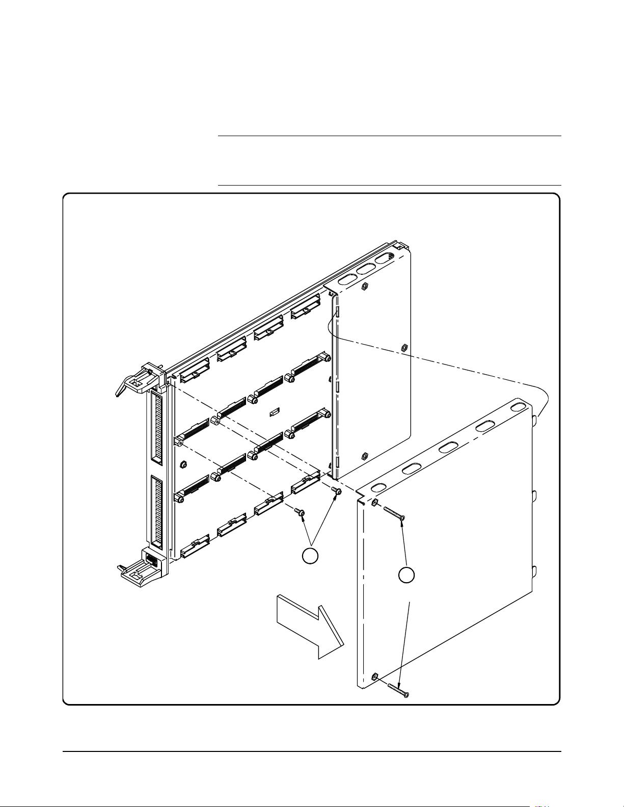
Installing SCPs: Step 1, Removing the Cover HP E1422
2
Remove the SCP
Retaining Screws
1
Remove 2 screws ( #10 Torx);
lift front and sli de out tabs
E1520 REMVLEFT
Getting Started 23Chapter 1
Page 24
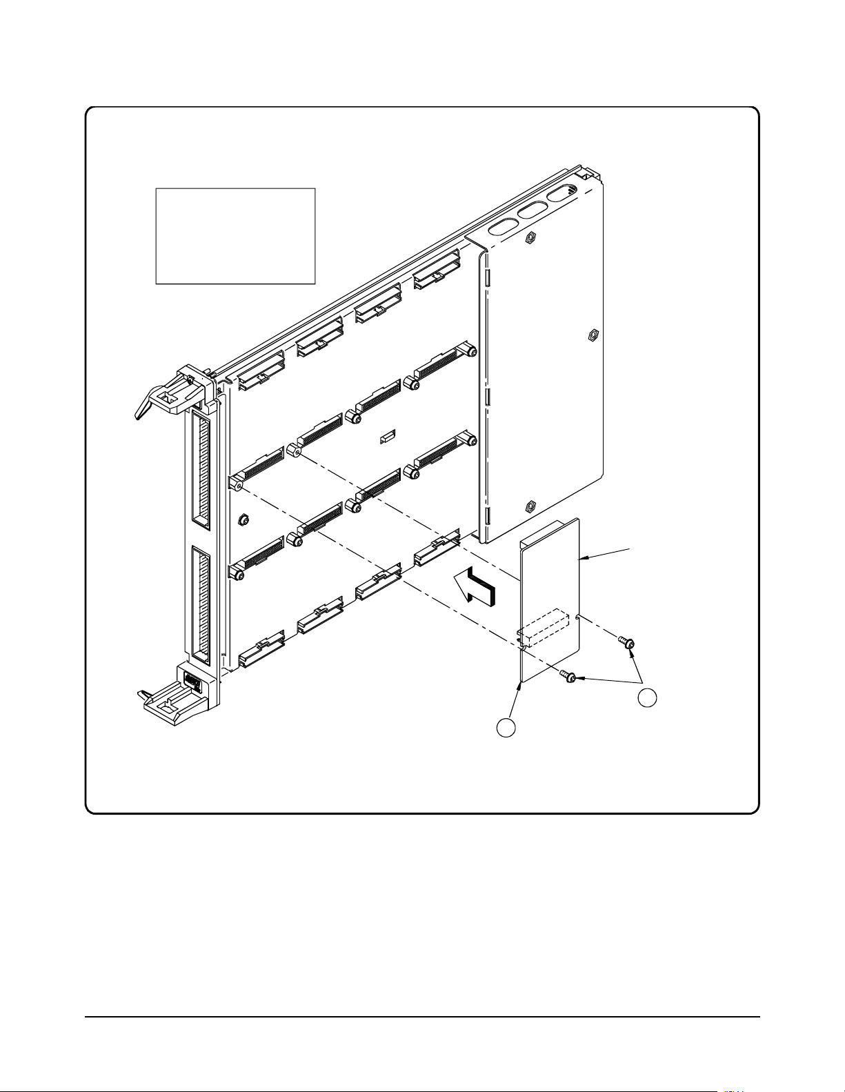
Installing SCPs: Step 2, Mounting an SCP
CAUTION
Use approved Static
Discharge handling
procedures when handling
the HP E1413 Scanning
A/D Module and the SCP s.
E1520 INSLSCP
1
Align the SCP
Connectors with the
Module Connec to rs
and then Push in
SCP
2
Tighten the SCP
Retaining Screws
24 Getting Started Chapter 1
Page 25
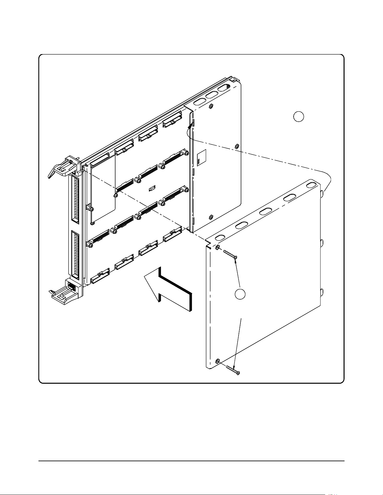
Installing SCPs: Step 3, Reinstalling the Cover HP E1422
1
Line up the 3 Tabs
with the 3 Slots;
then lower cov er
onto the Modul e
E1520 INSTLEFT
2
Tighten
2Screws
Getting Started 25Chapter 1
Page 26
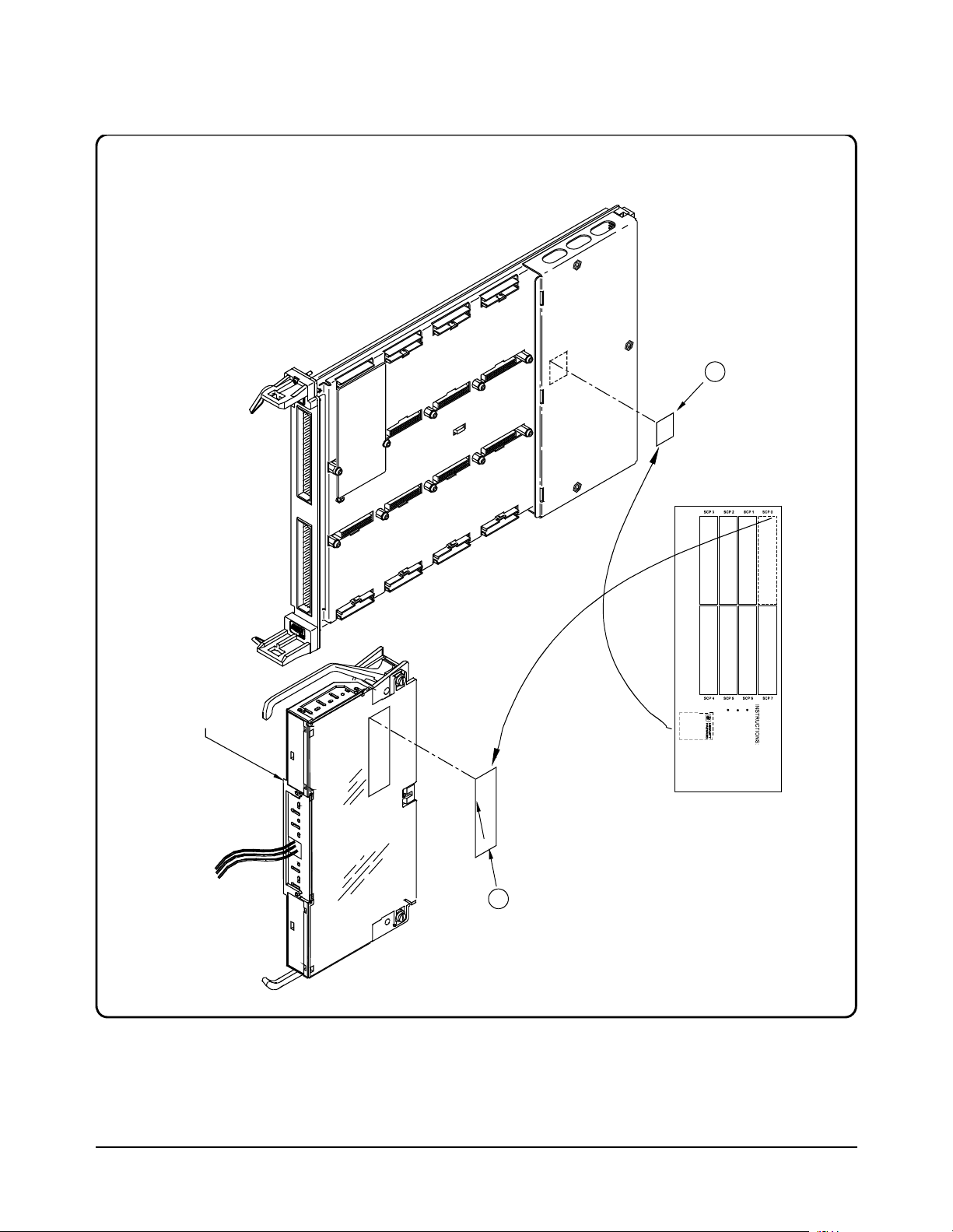
Installing SCPs: Step 4, Labeling
Peel off c orrec t
Label from Card and
Stick on the
appropriate place on
the Co ver
1
Term in al Module
(Connect to A/D
Module L ater)
Stick-onLabel furnished with the SCP
(HP part number: E15xx-84304)
2
Peel off Lab el from
Card and Stick on
the Terminal
Module to be
Connected to the
A/D Module
26 Getting Started Chapter 1
Page 27

Disabling the
Input Protect
Feature
(optional)
Disabling the Input Protect feature voids the HP E1422’s warranty. The Input
Protect feature allows the HP E1422 to open all channel input relays if any input’s
voltage exceeds ±19 volts (±6 volts for digital I/O SCPs). This fe ature will help to
protect the card’s Signal Conditioning Plug-ons, input multiplexer, ranging
amplifier, and A/D from destructive voltage le vels. The le vel that trips the
protection function has been set to provide a high probability of protection. The
voltage level that is certain to cause damage is somewhat higher. If in your
application the importance of completing a measurement run outweighs the
added risk of damage to your HP E1422, you may choose to disable the Input
Protect feature.
Voids Waranty! Disabling the Input Protection Feature voids the HP E1422’s warranty.
To disable the Input Prote ction feature, locat e and cut JM2202. Make a singl e cut in
the jumper and bend the adjace nt ends ap art. Se e foll owing i llust ration for locat ion
of JM2202.
Disabling
Flash Memory
Access
(optional)
The Flash Memory Protect Jumper (JM2201) is shipped in the “PROG” position.
We recommend that you leave the jumper in this position so that all of the
calibration commands can function. Changing the jumper to the protect position
will mean you won't be able to execute:
•The SCPI calibration command CAL:STORE ADC | TARE
•The register-based calibration commands STORECAL, and STORETAR
•Any application that installs firmware-updates or makes any other
modification to Flash Memory through the A24 window.
With the jumper in the “PROG” po sition, you ca n completely ca librate one or mor e
HP E1422s without removing them from the application system. An HP E1422
calibrated in its working environment will in general be better calibrated than if it
were calibrated separate from its application system.
The multimeter you use dur ing the per i odi c ca li bra ti on c ycl e should be considered
your calibration transfer standard. Have your Calibration Organization control
unauthorized access to its calib ration cons tants. See the HP E1422 Service Manual
for complete information on HP E1422 periodic calibration.
If you must limit access to the HP E1422's calibration constants, you can place
JM2201 in the protected position and cover the shield retaining screws with
calibration stickers. See following illustration for location of JM2201.
Getting Started 27Chapter 1
Page 28

Accessing and Locating JM2201 and JM2202 HP E1422
Flash MemoryProtect Jumper
Default = PROG
(recommended)
JM2201
E1413 FIG1-3
JM2202
1 Locate
2Cut
3 Bend
Input Protect Jump er
Warning: Cutting this Jumpe r
Voids Your Warranty!
28 Getting Started Chapter 1
Page 29

Installing the Module
Installation of the HP E1422 VXI module is covered in your HP Mainframe manual.
WARNING All instruments within the VXI mainframe are gr ounded thro ugh
the mainframe chassis. During insta llation, tighten the
instrument’ s retaining screws to secure the instrument to
the mainframe and to make the ground connection.
WARNING SHOCK HAZARD. Only qualified, service-trained personnel who
are aware of the hazards involved should install, configure, or
remove the VXI Module. Disconnect all power sources from the
mainframe, the Terminal Modules, and installed modules before
installing or removing a module.
Instrument Drivers
Two driver types are supplied on the HP Universal Drivers CD that comes with your
Instrument. There is a VXIpl ug&pl ay driver which includes a front panel program
and help file. In addition there is also a down-loadable driver for the HP E1406A
Command Module. Follow the instructions that are presented by the CD setup
program. Also view the readme .txt file pro vided wit h the VXIplug&pl ay driver for
possible update information.
About Example Programs
Examples on CD All example programs mentioned by file name in this manual are available on the
HP Universal Drivers CD supplied with your HP E1422. Again see the readme.txt
file for the specific file locations of these examples.
Example
Command
Sequences
Typical Example
program
Where programming concept s ar e discussed in this manual, the commands to send
to the HP E1422 are shown in the form of command sequences. These are not
example programs because t hey are not written in a ny computer language. Th ey are
meant to show the HP E1422 SCPI commands in th e sequ ence the y shoul d be se nt.
Where necessary th ese sequences include comments to describ e program flow and
control such as loop - end loop, and if - end if. See “Example SCPI Command
Sequence” on page 134. for an example. For VXIplug&play users, there is an
“Example VXIplug&play Driver Function Sequence” on page 135.
The Verify program (file name ve rif.cpp) is printed below to show a typical
VXIplug&play program for the HP E1422.
Getting Started 29Chapter 1
Page 30

Verifying a Successful Configuration
An example ’C’ progra m source is s hown on th e fol lowing p ages. T his pr ogram is
included on your HP Universal Drivers CD that comes with your HP E1422A (file
name verif.cpp). The program uses the *IDN? query command to verify the HP
E1422 is operational and r esponding t o commands. The program also has an error
checking function ( check( )). It is important to include an instrument error checking
routine in your programs, particularly your first trial programs so you get instant
feedback while you are learning about the HP E1422. Compile this program
according to the plug&play help file (hpe1422.hlp) topics "Introduction to
Programming"
Environments".
/*******************************************************************************
verif.cpp
This example program verifies your instrument installation by reading the
instrument IDs and then querying for and printing the SCP types found.
Use the "Copy Button" in the Help File’s "Example" window to place this code
into the clipboard, then paste this code text into your development tool’s
editor window. Similarly, "Copy" the actual example code from the help file’s
"Example" window and paste it into the location provided below.
This program should be compiled in the ’large’ memory model.
→"Compiling and Linking Programs Using Integrated
link with the hpe1422_32.lib - library file
*******************************************************************************
*/
#include <stdio.h>
#include <stdlib.h>
#include <string.h>
#include <hpe1422.h> /* include the driver header file */
/* GPIB-VXI addressing (0 is the interface number, 208 is the */
/* instrument logical address, INSTR is a VISA resource type) */
#define INSTR_ADDRESS "GPIB-VXI0::208::INSTR"
ViSession addr;
ViStatus errStatus;
/* Function Prototypes */
void main (void); /* Main function */
void rst_inst(void); /* Resets the instrument and sends a device clear */
void reads_instrument_id(void); /* reads instrument software revision */
void check (ViSession addr, ViStatus errStatus); /* checks module errors */
/*******************************************************************************/
void main (void) /* Main function */
{
ViChar err_message[256];
/* Set the session and status variables */
#if defined(__BORLANDC__) && !defined(__WIN32__)
_InitEasyWin();
#endif
30 Getting Started Chapter 1
Page 31

/* open device session and reset the instrument; check if successful */
errStatus = hpe1422_init(INSTR_ADDRESS,0,0,&addr);
if( VI_SUCCESS > errStatus)
{
hpe1422_error_message( addr, errStatus, err_message);
printf("Unable to open %s\n", INSTR_ADDRESS);
printf("hpe1422_init() returned error message %s\n", err_message);
return;
}
rst_inst(); /* Resets the instrument and sends a device clear */
reads_instrument_id(); /* Reads instrument software revision */
/* close the device session */
hpe1422_close(addr);
}
/****************************************************************************/
void rst_inst(void)
/* Function to set the interface timeout period, resets the instrument, */
/* waits for completion of reset, and sends a device clear to enable */
/* the instrument to receive a new command */
{
ViInt32 result;
/* set timeout to allow completion of reset */
errStatus = hpe1422_timeOut(addr, 5000);
check(addr, errStatus);
/* reset the instrument */
errStatus = hpe1422_reset(addr);
check(addr, errStatus);
/* wait for completion of *RST */
errStatus = hpe1422_cmdInt32_Q(addr,"*OPC?",&result);
check(addr, errStatus);
/* send a device clear to enable new commands to be sent to the instrument */
errStatus = hpe1422_dcl(addr);
check(addr, errStatus);
/* enables automatic error checking after each driver call */
errStatus = hpe1422_errorQueryDetect( addr, VI_TRUE);
}
/****************************************************************************/
void reads_instrument_id(void)
/* Function uses a hpe1422__revision_query to read the software revision */
/* string. */
{
ViChar driver_rev[256];
ViChar instr_rev[256];
/* Query the instrument for its firmware revision */
errStatus = hpe1422_revision_query(addr, driver_rev, instr_rev);
/* Print the results */
printf("The instrument driver’s revision is %s\n", driver_rev);
printf("The instrument’s firmware revision is %s\n", instr_rev);
}
/****************************************************************************/
Getting Started 31Chapter 1
Page 32

/****************************************************************************/
/* error checking routine */
void check (ViSession addr, ViStatus errStatus)
{
ViInt32 err_code;
ViChar err_message[256];
if(VI_SUCCESS > errStatus)
{
hpe1422_dcl(addr); /* send a device clear */
if(hpe1422_INSTR_ERROR_DETECTED == errStatus)
{
/* read instrument error until error queue is empty*/
do
{
hpe1422_error_query( addr, &err_code, err_message);
if(err_code != 0) printf("Instrument Error : %ld, %s\n", err_code,
err_message);
}
while(err_code != 0);
}
else
{
/* query the instrument */
hpe1422_error_message( addr, errStatus, err_message);
/* display the error */
printf("Driver Error : %ld, %s\n", errStatus, err_message);
}
}
return;
}
32 Getting Started Chapter 1
Page 33

About This Chapter
This chapter shows how to pla n and connect fiel d wiring to the HP E1422’s
Terminal Module. The ch apter expl ains proper connection of analog signals
to the HP E1422, both two-wire voltage type and four-wire resistance type
measurements. Connections for ot her measu rement t ypes (e .g., str ain usi ng
the Bridge Completion SCPs) refer to the specific SCP ma nual. Chapter
contents include:
Chapter 2
Field Wiring
• Planning Your Wiring Layout. . . . . . . . . . . . . . . . . . . . . . . . . . . . . 33
• Faceplate Connector Pin-Signal Lists. . . . . . . . . . . . . . . . . . . . . . . 37
• Optional Terminal and Connector Modules . . . . . . . . . . . . . . . . . . 38
• Reference Temperature Sensing with the HP E1422 . . . . . . . . . . . 42
• Preferre d Measurement Connections . . . . . . . . . . . . . . . . . . . . . . . 44
• Connecting the On-board Thermistor. . . . . . . . . . . . . . . . . . . . . . . 47
• Wiring and Attaching the Terminal Module . . . . . . . . . . . . . . . . . . 48
• Removing the HP E1422 Terminal Modules . . . . . . . . . . . . . . . . . 50
• Adding Components to the Terminal Module. . . . . . . . . . . . . . . . . 52
• Spring and Screw Terminal Module Wiring Maps . . . . . . . . . . . . . 53
Planning Your Wiring Layout
The first point to understand is that the HP E1422 makes no assumptions
about the relations hip between S ignal Conditioni ng Plug-on (SCP) f unction
and the position in the HPE1422 that it can occupy. You can put any type
of SCP into any SCP position. There are, however, some fac tors you should
consider when planning what mix of SCPs should be installed in e ach of your
HP E1422s. The following discussions will help you understand these
factors.
SCP Positions and
Channel Numbers
The HP E1422 has a fixed r elationship between Signa l Conditioning Plug-on
positions and the channels the y connect to. Each of the eig ht SCP positi ons
can connect to eight channe ls. Figure 2-1 sh ows the channel number to SCP
relationship.
Field Wiring 33Chapter 2
Page 34

SCP
Position 0
(on-board addresses 00-07)
SCP
Position 1
(on-board addresses 08-15)
Terminal
Module
Note: Each channel line represents
Both a Hi and Lo signal line.
Range Amp
16-Bits
A/D
Converter
SCP
Position 2
(on-board addresses 16-23)
SCP
Position 3
(on-board addresses 24-31)
SCP
Position 4
(on-board addresses 32-39)
SCP
Position 5
(on-board addresses 40-47)
Terminal Module
SCP
(on-board addresses 48-55)
(on-board addresses 56-63)
Position 6
SCP
Position 7
Figure 2-1. Channel Numbers at SCP Positions
34 Field Wiring Chapter 2
Page 35

Sense SCPs and
Output SCPs
Some SCPs provide input signal conditionin g (sense SCPs such as filters and
amplifiers) while others provide stimulus to your measurement circuit
(output SCPs such as curr ent sources and strain bridge completion). In
general, channels at output SCP positions are not used for external signal
sensing but are paired wit h channels of a sense SCP. Two points to r emember
about mixing output and sense SCPs:
1. Paired SCPs (an output and a sense SCP) may reside in separate
HP E1422s. SCP outputs are adjusted by *CAL? to be within a
specific limit. The Engineeri ng Unit (EU) conversio n used for a sense
channel will assum e the calibrated value for the output channel.
2. Output SCPs while providing st imulus to your measurement circuit
reduce the number of external sense channels available to your
HP E1422.
Figure 2-2 illustrat es an example of "pairing" output SCP channe ls with sense
SCP channels (in this example, four-wire resistance measurements).
Figure 2-2. Pairing Output and Sense SCP Channels
Field Wiring 35Chapter 2
Page 36

Planning for
Thermocouple
Measurements
Note The isothermal reference temperature measurement made by an HP E1422
Note To make good low-noise measurements you must us e shielded wiring from
Using either the Screw Ter minal or Sprin g Terminal Modules y ou can wir e
your thermocouples and your ther mocouple refe rence temper ature sens or to
any of the HP E1422’s channels. When you execute your scan list, you only
have to make sure that the reference temper ature sensor is specified in the
channel sequence before any of the associated thermocouple channels.
External wiring and connect ions to the HP E1422 are made using Ter minal
Modules (see Figures 2-4 through 2-6).
applies only to thermocouple measurements made by that instrument. In
systems with multiple HP E1422s, each instrument must make its own
reference measurements. The reference measurement made by one
HP E1422 can not be used to compensate thermocouple measurements
made by another HP E1422.
the device under test to the Terminal Module at the HP E1422. The shield
must be continuous through any wiring panels or isothermal reference
connector blocks and must be grounded at a single point to prevent ground
loops. See "Preferred Measurement Connections" later in this section and
“Wiring and Noise Reduction Methods” on page 421.
36 Field Wiring Chapter 2
Page 37

Faceplate Connector Pin-Signal Lists
Figure 2-3 shows the Fac eplate Connector Pi n Signal List for t he HP E1422.
Figure 2-3. HP E1422A Faceplate Connector Pin Signals
Field Wiring 37Chapter 2
Page 38

Optional Terminal and Connector Modules
The HP E1422 is comprised of the main A/D module and optionally, a
Connector or Terminal Modul e. The Option 001 Connector Module provides
16 RJ-45 jacks to allow easy connect ion of the HP E1422A to Remote Signal
Conditioning Units (RSCUs) li ke the HP E1529A Remote Strain
Conditioning Unit. Optional conventional terminal modules include a
Terminal Module with screw clamped terminal blocks (Option 011), and
another with spring clamped terminal blocks (Option 013).
The Spring Terminal Module and Screw Terminal Module provide:
•Terminal connections to field wiring.
-- Allows a mix of direct field wiring with some connections to
Remote Signal Conditioning Units
•Strain relief for the wiring bundle.
•Reference junction temperature sensing for thermocouple
measurements.
•Ground to Guard connections for each channel.
The RJ-45 Connector Module provides:
•Easy mass terminated plug-in connection to HP Remote Signal
Conditioning Units (RSCUs).
The SCPs and
Terminal Module
Terminal Module
Layout
WARNING When handling user wiring connected to the Terminal Module,
•Allows some direct analog or digital field wiring to be connected to
RJ-45 modular plugs that are then plu gged int o the Connec tor Mo dule.
•Note: Since the RJ-45 Con nector Modul e was des igned for connect ion
to RSCUs, it doesn’t provide an on-board isothermal reference
thermistor or conne cti on to the HP E1422A’s on-board current source.
This means that the RJ-45 Terminal Module is not suitable for direct
connection to thermocouples.
Each SCP includes a set of la bels to map that SCP's cha nnels to the Terminal
Module's terminal blocks. See “Installing SCPs: Step 4, Labeling” on
page 26.
Figures 2-4 through 2 -6 show the layout and feature locat ion of the Terminal
Modules available for the HP E1422A.
consider the highest voltage present accessible on any
terminal. Use only wire with an insulation rating greater than
the highest voltage which will be present on the Terminal
Module. Do not touch any circuit element connected to the
Terminal Module if any other connector to the Terminal Module
is energized to more than 30VACRMS or 60VDC.
38 Field Wiring Chapter 2
Page 39

The RJ-45
Connector Module
RJ-45 Connector Module Pinout
for Std SCP I/O (even chs 0,2,4,6)
Ch0
Shield Gnd
RJ-45 Connector Module Pinout
for Std SCP I/O (odd chs 1,3,5,7)
Ch1
Shield Gnd
Ch2
-
+
12345678
Ch3
-
+
12345678
Ch4
Ch5
+
-
Ch2
Ch6
Shield Gnd
+
-
Ch3
Ch7
Shield Gnd
Figure 2-4 shows the HP E1422A Option 001 RJ-45 Connector Module with
connector pin numbering.
+=Hi
-=Lo
+=Hi
-=Lo
0
1
8
R
elease
9
1
6
1
7
!
R
2
ead M
4
anual for R
2
5
elease Instructions
3
2
3
3
4
0
4
1
R
4
elease
8
4
9
5
6
5
7
SCP position 0, chs 0-6 and 1-7
SCP position 1, chs 8-14 and 9-15
SCP position 2, chs 16-22 and 17-23
SCP position 3, chs 24-30 and 25-31
SCP position 4, chs 32-38 and 33-39
SCP position 5, chs 40-46 and 41-47
SCP position 6, chs 48-54 and 49-55
SCP position 7, chs 56-62 and 67-63
Figure 2-4. RJ-45 Connector Module and Pin-out
Spring Terminal
Module Layout
Caution WIRING THE TERMINAL MODULES. When wiring to the
Figure 2-5 shows the HP E1422A Option 013 Spring Terminal Module
features and jumper locations.
terminal connectors on the screw clamp and spring clamp
Terminal Module, be sure not to exceed a 5mm strip back of
insulation to prevent the possibility of shorting to other wiring
on adjacent terminals.
Field Wiring 39Chapter 2
Page 40

g
Sockets for Guard to
Ground Connections
Termi nal Block f or
Input Connections
Jumper to select for
On-board or Remote
Temperat ure Sensing
On-board Thermisto r
for Temperat ure Sensi n
Terminal Bloc k with
Remote Tem perature S ensing ,
Trigger, and other Connections
Figure 2-5. HP E1422A Spring Terminal Module
40 Field Wiring Chapter 2
Page 41

Screw Terminal
Module Layout
Figure 2-6 shows the HP E1422A Option 011 Screw Terminal Module
features and jumper locations.
Figure 2-6. HP E1422A Screw Terminal Module
Field Wiring 41Chapter 2
Page 42

Reference Temperature Sensing with the HP E1422
The Screw Terminal and Spring Terminal Modules provides an on -board thermistor
for sensing isother mal ref erence temper ature of the t erm inal b locks. Also prov ided
is a jumper set (J1 in Figures 2-7 and 2-8) to route the HP E1422’s on-board current
source to a thermistor or RTD on a remote isothermal reference block. Figure 2-7
and Figure 2-8 show connect ions for both local and remote sensing. See “Connect ing
the On-board Thermistor” on page 47. for location of J1.
E1415 Terminal Module Field Wiring
HTI
LTI
HTS
LTS
Hnn
Lnn
On-Board
Current Source
REM
J1
Any Sense
Channel
ON
BOARD
Figure 2-7. On-Board Thermistor Connection
E1415 Terminal Module Field Wiring
HTI
LTI
REM
ON
BOARD
On-Board
Current Source
J1
Any Sense
Channel
HTS
LTS
Hnn
Lnn
Figure 2-8. Remote Thermistor or RTD Connections
42 Field Wiring Chapter 2
Page 43

Terminal Module
Considerations for
TC Measurements
The isothermal characteristics of the HP E1422 Terminal Module are crucial for
good TC readings and can be affected by any of the following factors:
1. The clear plastic cover must be on the Terminal Module.
2. The thin white mylar thermal barrier must be inserted over the Terminal
Module connector. This prevents airflow from the HP E1422 A/D Module
into the Terminal Module.
3. The Terminal Module must also be in a fairly stable temperature
environment, and it is best to minimize the te mper ature gradient betwe en the
HP E1422 module and the Terminal Module.
4. The VXI mainframe cooling fan fil ters must be clean and there should be as
much clear space in front of the fan intakes as possible.
5. Recirculating warm air inside a closed rack cabinet can cause a problem if
the Terminal Module is suspended into ambient air that is significantly
warmer or cooler. If the mainframe recess is mounted in a rack with both
front and rear doors, closing both doors helps keep the entire HP E1422 at a
uniform temperature. If there is no front door, try opening the back door.
6. HP recommends that the cooling fan switch on the back of the of an HP
E1401 Mainframe is in the "High" position. The normal variable speed
cooling fan control can make the internal HP E1422 module temperature
cycle up and down, which affects the amplifiers with these uV level signals.
Field Wiring 43Chapter 2
Page 44

Preferred Measurement Connections
IMPORTANT!
For any A/D Module t o scan channels a t high speeds, it must use a very short sample
period (<10µsecond for the HP E1422). If significant normal mode noise is
presented to its inputs, that noise will be part of the measurement. To make quiet,
accurate measurements in ele ct ri cal ly nois y environments, use properly connected
shielded wiring between the A/D and the device under test. Figure 2-9 shows
recommended connecti ons for p owered tr ansducers , thermocou ples, and resis tance
transducers. (See Appendix D page 421 for more information on Wiring
Techniques).
Notes 1. Try to install A nalog SCPs r elative to Digital I/O as shown in "S eparating
Digital and Analog Signals" in Appendix .
2. Use individually shielded, twisted-pair wiring for each channel.
3. Connect the shield of each wiring pair to the corresponding Guard (G)
terminal on the Terminal Module (see Fi gure 2-10 for schematic of Guard to
Ground circuitry on the Terminal Module).
4. The Terminal Module is shipped with the Ground-Guard (GND-GRD)
shorting jumper installed for each channel. These may be left inst alled or
removed (see Figure 2-1 1 t o remove the jumpe r), depende nt on the fol lowing
conditions:
a. Grounded Transducer with shield connected to ground at the
transducer: Low frequency ground loops (DC and/or 50/60Hz) can
result if the shield is also grounded at the Terminal Module end. To
prevent this, remove the GND-GRD jumper for that channel (Figure 2-9
A/C).
b. Floating Transducer with shield connected to the transducer at the
source: In this case, the best performance will mos t like ly be ac hieved by
leaving the GND-GRD jumper in place (Figure 2-9 B/D).
3. In general, the GND-GRD jumper can be lef t in place unless it is necessary to
remove to break low frequency (below 1 kHz) ground loops.
4. Use good quality foil or braided shield signal cable.
5. Route signal leads as far as possible from the sources of greatest noise.
6. In general, don’t connect Hi or Lo to Guard or Ground at the HP E1422.
7. It is best if there is a D.C. path somewhere in the system from Hi or Lo to
Guard/Ground.
8. The impedance from Hi to Guard/Ground should be the same as from Lo to
Guard/Ground (balanced).
9. Since each system is different, don’t be afraid to experiment using the
suggestions presented here until you find an acceptable noise level.
44 Field Wiring Chapter 2
Page 45

Device
Under Test
Device
Under Test
pressure
pressure
to
to
P
V
P
V
power
power
power
power
ShieldShield
A
Example for
Powered
Transducers
Shield
B
Hi
Lo
Guard
RemoveJumperto
break Ground Loop
(shield connected to
ground at transducer)
Hi
Lo
Guard
Leave Jumper
in Place
(transducer floating)
Device
Under Test
Device
Under Test
Shield
Example for
Thermocouples
Shield
Shield
Example for
Resistive
Transducers
C
D
E
Hi
Lo
Guard
Hi
Lo
Guard
Hi
Lo
Guard
RemoveJumperto
break Ground Loop
(shield connected to
ground at transducer)
Leave Jumper
in Place
(transducer floating)
Jumper may be left in
place, since CurrentLo( + )
is at E1415 GND Potential
Current Hi ( - )
Current Lo ( + )
Figure 2-9. Preferred Signal Connections
Field Wiring 45Chapter 2
Page 46

External Connections
SC
G0
TerminalModule
P
1KΩ
For each
SCP Position
.1 µF
G7
.1 µF
GND to GRD Jumper
(removable)
1KΩ
GND to GRD Jumper
(removable)
Figure 2-10. GRD/GND Circuitry on Terminal Module
Removing Guard to
Ground on Channel 00
10 KΩ
10 KΩ
Figure 2-11. Grounding the Guard Terminals
46 Field Wiring Chapter 2
Page 47

Connecting the On-board Thermistor
The following figures show how to use the HP E1422 to make temperature
measurements using the on-board Thermi stor or a remote reference sensor. The
Thermistor is used for reference junction temperature sensing for thermocouple
measurements. Figure 2-12 shows the configuration for the HP E1422A’s Spring
Terminal Module, Figure 2-6 shows the configuration for the Screw Terminal
Module. See “Reference Tempe rature Sens ing with the HPE1422” on page 42. for
a schematic diagram of the reference connections.
UnderCover
Place both J1 jumpers here to
connect current source to
on-board thermistor RT1. Sense
RT1 by connecting any sense
channels to terminals HTS and
LTS.
Place both J1 jumpers here to
route current source to terminals
HTI a nd LTI. Connec t these
terminals to remote thermistor or
RTD. Sense with any sense
channel.
ON BOARD
REMote
See Figure 2-13 on page 48 to remove the cover
Figure 2-12. Temperature Sensing for the Terminal Module
Field Wiring 47Chapter 2
Page 48

Wiring and Attaching the Terminal Module
Figures 2-13 and 2-14 show how to open, wire, and attach the terminal module to
an HP E1422.
1
Remove Clear Cover.
A. Release screws.
B. Press tab forward
and release.
Tab
3
Make Connec tions (Spring Clamp)
Depress terminal lever(s). Insert
wire(s) into terminal(s). Re lease levers.
Use wire size 20-26 AWG
5mm
0.2"
Special tool HP P/N 8710-2127
(Shipped with Terminal Module)
Remove and Retain Wi rin g Exi t Pan el
2
(Screw Type)
Remove 1 of the 3
wire exit panels.
Use wire
size 16-26
AWG
5mm
0.2"
VW1 Flammability
Rating
Insert wire into terminal.
Tighten screw.
Route Wiring4
Tighten wraps to
secure wires.
Figure 2-13. Opening and Wiring the E1422’s Terminal Module
48 Field Wiring Chapter 2
Page 49

Figure 2-14. Closing and Attaching the HP E1422 Terminal Module
Field Wiring 49Chapter 2
Page 50

Removing the HP E1422 Terminal Modules
Figure 2-15 shows how to remov e the Spring Terminal and Screw Terminal Modules
from the HP E1422A.
Release the two extr ac tio n
1
levers and push bo th levers
out simultane ous ly
Extraction L ever
Use a small screwdriver
to pry and release the
two extraction levers
Free and remove th e Terminal
2
Module from the A/D Module
Extraction Lever
HP E1415
Extraction L ever
Figure 2-15. Removing the Screw and Spring Terminal Modules
50 Field Wiring Chapter 2
Page 51

Attaching and Removing the HP E1422 RJ-45 Module
Figure 2-16 shows how to remove the RJ-45 Terminal Module.
1
Install on HP E1422A
2
Push in the Extraction Levers to Lock
the Terminal Module onto the
HP E1422A
Extraction
Levers
3
Releasing the Extraction Levers to Remove the Termi nal Module
Screwdriver
With 1/8"
Blade
Figure 2-16. Removing the RJ-45 Terminal Module
Field Wiring 51Chapter 2
Page 52

Adding Components to the Terminal Module
The back of the terminal module P.C. board provid es surface mount pads which y ou
can use to add serial and parallel components to any channel’s signal path. Figure
2-17 shows additional component locator information (see the schematic and pad
layout information on the back of the teminal module P.C. board). Figu re 2-18 shows
some usage example schematics.
Figure 2-17. Additional Component Location
Figure 2-18. Series & Parallel Component Examples
52 Field Wiring Chapter 2
Page 53

Spring and Screw Terminal Module Wiring Maps
Figure 2-19 shows the Spring Terminal Module wiring map.
Top
All wiring entering Terminal
Module passes under this
strain relief bar
H24
L24
G24
H25
L25
G25
H26
L26
G26
H27
L27
G27
H28
L28
G28
H29
L29
G29
H30
L30
G30
H31
L31
G31
H16
L16
G16
H17
L17
G17
H18
L18
G18
H19
L19
G19
H20
L20
G20
H21
L21
G21
H22
L22
G22
H23
L23
G23
H08
L08
G08
H09
L09
G09
H10
L10
G10
H11
L11
G11
H12
L12
G12
H13
L13
G13
H14
L14
G14
H15
L15
G15
GND
GND
GND
GND
LTS
HTS
LTI
HTI
GND
TRIG
GND
LCAL
HCAL
LOHM
HOHM
GND
GND
GND
H00
L00
G00
H01
L01
G01
H02
L02
G02
H03
L03
G03
H04
L04
G04
H05
L05
G05
H06
L06
G06
H07
L07
G07
Heavy line indicates the
side of the terminal b lock
that the wire enters
Figure 2-19. Spring Terminal Module Full-Size Wring Map
G32
L32
H32
G33
L33
H33
G34
L34
H34
G35
L35
H35
G36
L36
H36
G37
L37
H37
G38
L38
H38
G39
L39
H39
G40
L40
H40
G41
L41
H41
G42
L42
H42
G43
L43
H43
G44
L44
H44
G45
L45
H45
G46
L46
H46
G47
L47
H47
G48
L48
H48
G49
L49
H49
G50
L50
H50
G51
L51
H51
G52
L52
H52
G53
L53
H53
G54
L54
H54
G55
L55
H55
G56
L56
H56
G57
L57
H57
G58
L58
H58
G59
L59
H59
G60
L60
H60
G61
L61
H61
G62
L62
H62
G63
L63
H63
Field Wiring 53Chapter 2
Page 54

Figure 2-20 shows the Screw Terminal Module wiring map
Figure 2-20. Screw Terminal Module Full-Size Wiring Map
54 Field Wiring Chapter 2
Page 55

Chapter 3
Programming the HP E1422A & HP E1529A
for Remote Strain Measurement
About This Chapter
This chapter describes using the HP E1422A in combination with the
HP E1539A Remote Channel SCP and HP E1529A Remote Strain
Conditioning Units to make large channel count strain measuremen ts. We
show the system used in a strictly data acquisition mode where after
configuration it is driven by a channel list you define (the Scan List), and
sends the measurements to the unit’s FIFO buffer and Current Value Table
(CVT) for transfer to your computer. Of course you can also create control
algorithms that execute concurrently with the Scan List driven data
acquisition operation. Chapter 4 and Chapter 5 cover general data
acquisition and contr ol programming with algo rithms. This chapter a ssumes
that you are the expert when it comes to making strain measurements so
we’re simply going to show you how to make your strain measureme nts with
the HP Remote Strain Measuring System (HP E1422A, HP E1539As, and
HP E1529As). The chapter will cover:
• Instrument Setup for Remote Strain Measurements. . . . . . . . . . . . 56
-- Preparing the HP E1422A for Installation . . . . . . . . . . . . . . . . . 56
-- Installing User Selected 1/4 Bridge Resistors (optional) . . . . . . 57
-- Connecting HP E1529As to the HP E1422A . . . . . . . . . . . . . . . 60
-- Connecting Excitation Supplies . . . . . . . . . . . . . . . . . . . . . . . . . 65
• Connecting the HP E1529A to Strain Gages . . . . . . . . . . . . . . . . . 66
-- Channel Connector Pin-to-Signal Relationship . . . . . . . . . . . . . 66
-- HP E1529A Bridge Configurations . . . . . . . . . . . . . . . . . . . . . . 67
• Connecting to the HP E1529A’s Dynamic Strain Ports . . . . . . . . . 70
-- Dynamic Strain Port Offset Control . . . . . . . . . . . . . . . . . . . . . . 72
• Remote Strain Channel Addressing . . . . . . . . . . . . . . . . . . . . . . . . 73
-- Runtime Remote Scan Verification. . . . . . . . . . . . . . . . . . . . . . . 73
• Programming for Remote Strain Measurement . . . . . . . . . . . . . . . 75
-- Description of Strain Measurement . . . . . . . . . . . . . . . . . . . . . . 75
Measure Strain Using Built-in Strain EU Conversion . . . . . . 76
Measure Strain Using User Specified EU Conversion . . . . . . 80
Measure Bridge Voltages and Convert to Strain. . . . . . . . . . . 83
• Verifying Correct Bridge Completion (Shunt Cal). . . . . . . . . . . . . 87
• Built-in Strain Conversion Equations. . . . . . . . . . . . . . . . . . . . . . . 89
Programming the HP E1422A & HP E1529A for Remote Strain Measurement 55Chapter 3
Page 56

Instrument Setup for Remote Strain Measurements
This section involves:
•Preparing the HP E1422A for installation into a VXIbus Mainframe
•Preparing the HP E1429A for use
•Connecting the HP E1422A to HP E1529A Remote Stra in Completion
units.
•Connecting Excitation power supplies to the HP E1529A
•Connecting strain bridges to the HP E1529A
Preparing the
HP E1422A for
Installation
Overview Before we get into the s pecifics of co nfiguring a Re mote Strain Measuring
Each HP E1422A With HP E1539A SCPs
And HP E1529A Remote Strain Units
Can Support Up-To 512 Strain Gages
HP E1539A
SCP (Up-To 8)
The HP E1422A needs HP E1539A SCPs to control Remote Signal
Conditioning Units like the HP E1529A Remote Strain Conditioning Unit.
Chapter 1 “Getting Started” covers everything you need to do before you
install your HP E1422A in its Mai nframe. Thi s include s switch settings and
SCP installation. After performing the operations in Chapter 1, return here
for Remote Strain specific op erations.
System, it might help you to see what we are going to set-up. Figure 3-1
shows the components and c onnections of a remote strain measuring system.
The circled letters identify connections that will be referred to in later
sections.
Up-to 4 Excitation Supplies
B
HP E1529A
CA
s
1529A
E
P
A
p-to 16 H
U
HP E1529A
HP E1422A Multif unction
DAC Module Shown With
An Option 001 RJ-45
Connector Module
Up-to 32 Strain
Gages
Up-to 4 Excitation Supplies
Up-to 32 Strain
Gages
Figure 3-1. Components of the Remote Strain Measuring System
56 Programming the HP E1422A & HP E1529A for Remote Strain Measurement Chapter 3
Page 57

Preparing the
HP E1529A for Use
WARNING Ground the equipment: The Safety earth ground for the
WARNING The power cord is the only way to disconnect the HP E1529A
For most applications, the HP E1529A is ready for installation as delivered.
It is designed to be easily rack mounted in a system cabinet by its built-in
front panel extensio ns. All user connecti on are acce ssible on th e front p anel
with the exception o f the li ne-cord j ack whi ch is on the re ar of the un it. The
only pre-installat ion opera ti on you migh t need to consider is installa ti on of
user supplied quarter -bridge completion resistors. If your application
requires these, s ee “Installing Use r Selected 1/4 Bridge Resistors ( optional)”
in the following section.
HP E1529A is supplied through the ground conductor of the
power cable. Make sure your installation’s AC line supply
connectors provide a suita ble earth ground.
from AC power. Therefore, the power cord must be accessible
to the operator at all times. When the HP E1529A is mounted in
a system cabinet, the power cord need not be accessible since
the cabinet must have its own disconnect device.
Installing User
Selected 1/4 Bridge
Resistors (opt ional)
Perform this operatio n only if you require o ne or more HP E1529A channels
to provide 1/4 Bridge completion of other than 120
with experience solder ing components on printed circuit boards should
attempt this installation. The HP E1529A provides locations on its printed
circuit board to install your own 1/4 bridge completion resistors. Bridge
configuration commands then can switch your resistors into the bridge
completion circuits where you’ve installed custom value resistors.
Ω or 350Ω . Only those
WARNING Keep away from live circuits: Operating personnel must not
remove equipment covers or shields. Procedures involving the
removal of covers or shields are for use by service-trained
personnel only. Under certain conditions, dangerous voltages
may exist even with the equipment switched off. To avoid
dangerous electrical shock, DO NOT perform procedures
involving cover or shield removal unless you ar e qualified to do
so.
Removing the Top Cover Figure 3-2 shows how to access the printed circuit board where the user
specified resisto rs will be instal led. Notice that both a surface-mount as well
as a through-hole position is provided for each channel.
Programming the HP E1422A & HP E1529A for Remote Strain Measurement 57Chapter 3
Page 58

Tab
2
Unlatch Cover from
Bottom Cover Tab
on Each Side
Detail "A"
Figure 3-2. Removing the HP E1529A Top Cover
1
Loosen
Top Cover
Screw
3
Remove Top Cover
PC Board
See Detail "A"
58 Programming the HP E1422A & HP E1529A for Remote Strain Measurement Chapter 3
Page 59

Locating Resistors Figure 3-3 provides the relationship b etween P.C. board loc ation and bridg e
resistor channel number. The surface mount pads nearest the through-hole
locations are in parallel with them.
"Rxx" Indicates the
Channel Number
Through-Hole
R
R
E
E
S
S
-U
01-U
00
OROR
R
R
Resistor Positions
R
R
E
E
S
S
00-U
01-U
R
R
R
R
E
E
S
S
3-U
0
02-U
R
R
R
R
E
E
S
S
16-U
17-U
R
R
R
R
E
E
S
S
25-U
24-U
R
R
R
R
E
E
S
S
20-U
21-U
R
R
R
R
E
E
S
S
29-U
28-U
R
R
Surface-Mount
R
R
E
E
S
S
04-U
05-U
R
R
R
R
E
E
S
S
7-U
0
06-U
R
R
Resistor Positions
R
R
E
E
S
S
09-U
08-U
R
P401
P402
403
P
R
R
R
E
E
S
S
13-U
12-U
R
R
R
R
E
E
S
S
1-U
1
10-U
R
R
R
R
E
E
S
S
5-U
1
14-U
R
R
R
R
E
E
S
S
19-U
18-U
R
R
R
R
E
E
S
S
23-U
22-U
R
R
R
R
E
E
S
S
26-U
27-U
R
R
R
R
E
E
S
S
30-U
31-U
R
R
Figure 3-3. Locating User 1/4 Bridge Resistor Positions
Installing Resistors Figure 3-4 shows a typical us er selected 1/4 bri dge resistor instal lation. Note
that resistor inst allations can be accomplished from the top of the board
without further disas sembly. If you are inst alling through-hol e resistors, you
must be very careful to observe the specifie d maximum safe resistor lead
length to avoid shorti ng the resistor to the chassis.
Programming the HP E1422A & HP E1529A for Remote Strain Measurement 59Chapter 3
0.1"
2.54mm
PC Board
Chassis
Figure 3-4. Installing User 1/4 Bridge Resistors
Page 60

Connecting
HP E1529As to the
HP E1422A
The cable between an HP E1422A and each HP E1529A (connection "A" i n
Figure 3-1) is a standard type of cable used in computer Local Area
Networks (LANs). The HP E1529A can be any distance up-to 1000 feet
from the HP E1422A, and the interconnec t cable can be ea sily custom mad e
to fit the ins tallation. In fact, if your firm has an Information Technolog y
department, they may already be making or having made this same type of
cable assembly.
The cable assembly as a whole must comply with the TIA/EIA-568
Category 5 standard for LAN interconnecting cable. This is a performance
based standard and will insure that the HP E1422A will be able to make
accurate measurements from an HP E1529 A over the maximum cable length
of 1000 feet (305 meters). Additionally, the cable and connectors must be
shielded.
Cabling Supplies and
Tools
Overall-Shielded Twisted Pair (STP) TIE/EIA-568 Category 5 (4 twisted pairs)
Plenum Type: (Flame Retardant Jacket and FEP ‡Teflon insulation) 1586A
Non-Plenum Type: (PVC Jacket and polyolefin insulation) 1584A
Tables 3-1 and 3-2 show part numbers for supplies that will allow you to
quickly custom make high qua li ty cables for your installation. If you op t t o
have a third party build your cables, make certain they supply you with
cables that comply with the TIA/EIA-568 Category 5 standard and are
shielded. The part numbers shown here are those of major suppliers in the
industry. These numbers can be cross-referenced to other supplier’s
equivalent products.
Please note that safety st andards for wiring (f lammabil ity etc.) may apply t o
your installation and you should check applicable codes and standards in
your area and select the proper type of cable accordingly (plenum vs.
non-plenum types etc.).
Table 3-1.
Cable Part Numbers for Belden Wire & Cable Company
‡DuPont trademark
Table 3-2.
Connector Part Numbers for AMP Incorporated
RJ-45 Plug: (for solid conductors and round shielded cable) 5-569530-4
RJ-45 Plug: (for stranded conductors and round shielded cable) 5-569550-4
Strain Relief 558527-1
Hooded Boot: (replace X with 0=Gry, 1=Blk, 2=Lt. Almond,
3=Red, 4=Grn, 5=Blu, 6=Yel, 7=Org, 8=Wht, 9=Vio)
RJ-45: Plug Installation Tool with 8-position dies 2-231652-1
60 Programming the HP E1422A & HP E1529A for Remote Strain Measurement Chapter 3
569875-X
Page 61

Two Interconnect
Methods
Depending on which Termina l Module you or dered with yo ur HP E1422A,
there are two methods of interc onnecting an HP E1529A to the HP E1422A
(connection "A" in Figure 3-1).
The Option 001 RJ-45
Connector Module
HP E1422A Option 001
The RJ-45 Connector Module is used when mos t or all of HP E1422A SCP
positions contain an HP E1539A Remote Channel SCP. For RSCUs, you
just plug one end int o t he HP E1422A, and the other into the HP E1529A’s
Data Interface connector.Figure 3-5 shows this connection and includes a
schematic diagram of the RJ-45-to-RJ-45 cable. See Figure 2-4 on page 39
for on-board SCP chann el connect ion throu gh the RJ-45 connector module.
HP E1529A
Length up-to 1000 feet
ShieldShield
1
2
3
4
5
6
7
8
Wht/Grn
Grn
Wht/Org
Blu
Wht/Blu
Org
Wht/Brn
Brn
Twisted Pair
Twisted Pair Twisted Pair
Twisted Pair
1
2
3
4
5
6
7
8
Figure 3-5. Connecting HP E1529As to the RJ-45 Connector Module
TIA/EIA 568A
Wiring Diagram
Programming the HP E1422A & HP E1529A for Remote Strain Measurement 61Chapter 3
Page 62

Spring, and Screw
Terminal Modules
SCP Position Plug
Pin#
SCP Position 0
Addresses
10000 to 10131
SCP Position 1
Addresses
10800 to 10931
SCP Position 2
Addresses
11600 to 11731
SCP Position 3
Addresses
12400 to 12531
1 Analog+ (wht-green) HI 00 HI 01
2 Analog- (green) LO 00 LO 01
3 Cal+ (wht-orange) HI 02 HI 03
4 RS-485+ (blue) HI 04 HI 05
5 RS-485- (wht-blue) LO 0 4 LO 05
6 Cal- (orange) LO 02 LO 03
7 Trigger+ (wht-brown) HI 06 HI 07
8 Trigger- (brown) LO 06 LO 07
1 Analog+ (wht-green) HI 08 HI 09
2 Analog- (green) LO 08 LO 09
3 Cal+ (wht-orange) HI 10 HI 11
4 RS-485+ (blue) HI 12 HI 13
5 RS-485- (wht-blue) LO 1 2 LO 13
6 Cal- (orange) LO 10 LO 11
7 Trigger+ (wht-brown) HI 14 HI 15
8 Trigger- (brown) LO 14 LO 16
1 Analog+ (wht-green) HI 16 HI 17
2 Analog- (green) LO 16 LO 17
3 Cal+ (wht-orange) HI 18 HI 19
4 RS-485+ (blue) HI 20 HI 21
5 RS-485- (wht-blue) LO 2 0 LO 21
6 Cal- (orange) LO 18 LO 19
7 Trigger+ (wht-brown) HI 22 HI 23
8 Trigger- (brown) LO 22 LO 23
1 Analog+ (wht-green) HI 24 HI 25
2 Analog- (green) LO 24 LO 25
3 Cal+ (wht-orange) HI 26 HI 27
4 RS-485+ (blue) HI 28 HI 29
5 RS-485- (wht-blue) LO 2 8 LO 29
6 Cal- (orange) LO 26 LO 27
7 Trigger+ (wht-brown) HI 30 HI 31
8 Trigger- (brown) LO 30 LO 31
For mixed on-board SCP channels and RSCU operation, you can use the
spring type, or screw type terminal modules. For standard SCP channel
connections see Chapt er 2 “Fi el d Wir in g ” on p age 33. For remote channels
you connect the individual wires from each HP E1529A’s data interface
cable to the ap propriate terminals for remote channel operation. The
HP E1539A SCP is supplied with signal locator labels fo r each SCP position
on a Spring Terminal Module. No label is provided for the Screw terminal
module. Instead, Table 3-3 provides the relationship between each
HP E1439A signal name and associated terminal name as printed on the
Terminal Module.
Table 3-3.
SCP Signal Names - to - Terminal Names
HP E1539A Signal Name
(with EIA/TIA-568A
wire color-code)
Ter minal Name on
Terminal Module
(SCP’s low channel)
Terminal Name on
Terminal Module
(SCP’s High Channel)
62 Programming the HP E1422A & HP E1529A for Remote Strain Measurement Chapter 3
Page 63

SCP Position Plug
Pin#
SCP Position 4
Addresses
13200 to 13331
SCP Position 5
Addresses
14000 to 14131
SCP Position 6
Addresses
14800 to 14931
SCP Position 7
Addresses
156000 to 157131
1 Analog+ (wht-green) HI 32 HI 33
2 Analog- (green) LO 32 LO 33
3 Cal+ (wht-orange) HI 34 HI 35
4 RS-485+ (blue) HI 36 HI 37
5 RS-485- (wht-blue) LO 3 6 LO 37
6 Cal- (orange) LO 34 LO 35
7 Trigger+ (wht-brown) HI 38 HI 39
8 Trigger- (brown) LO 38 LO 39
1 Analog+ (wht-green) HI 40 HI 41
2 Analog- (green) LO 40 LO 41
3 Cal+ (wht-orange) HI 42 HI 43
4 RS-485+ (blue) HI 44 HI 45
5 RS-485- (wht-blue) LO 4 4 LO 45
6 Cal- (orange) LO 42 LO 43
7 Trigger+ (wht-brown) HI 46 HI 47
8 Trigger- (brown) LO 46 LO 47
1 Analog+ (wht-green) HI 48 HI 49
2 Analog- (green) LO 48 LO 49
3 Cal+ (wht-orange) HI 50 HI 51
4 RS-485+ (blue) HI 52 HI 53
5 RS-485- (wht-blue) LO 5 2 LO 53
6 Cal- (orange) LO 50 LO 51
7 Trigger+ (wht-brown) HI 54 HI 55
8 Trigger- (brown) LO 54 LO 55
1 Analog+ (wht-green) HI 56 HI 57
2 Analog- (green) LO 56 LO 57
3 Cal+ (wht-orange) HI 58 HI 59
4 RS-485+ (blue) HI 60 HI 61
5 RS-485- (wht-blue) LO 6 0 LO 61
6 Cal- (orange) LO 58 LO 59
7 Trigger+ (wht-brown) HI 62 HI 63
8 Trigger- (brown) LO 62 LO 63
Table 3-3.
SCP Signal Names - to - Terminal Names
HP E1539A Signal Name
(with EIA/TIA-568A
wire color-code)
Ter minal Name on
Terminal Module
(SCP’s low channel)
Terminal Name on
Terminal Module
(SCP’s High Channel)
Programming the HP E1422A & HP E1529A for Remote Strain Measurement 63Chapter 3
Page 64

Example Terminal
Module to HP E1529A
Connection
Figure 3-6 shows a typi cal c onnect ion to an HP E1529A through one of the
optional terminal modules . In this case, the con nection is to the l ow channel
on the HP E1539A in SCP position number 6 (chan nels 14800 - 14831). For
connection to other SCP positions, use the "Terminal Module Connection
Formula" from Figure 3-6 or the data from Table 3-3.
in 2
P
rom
F
in 1
P
m
ro
F
in 6
P
rom
F
in 3
P
rom
F
in 5
P
rom
F
in 4
P
rom
F
8
in 7
in
P
P
rom
rom
F
F
1
wht-grn
2
green
3
wht-org
4
blue
5
wht-blu
6
orange
7
wht-brn
8
brown
Terminal Module Connection Formula
SCP Low Channel SCP High Channel
SCP Pos. * 8 +
wht-grn
green
wht-org
orange
blue
wht-blu
wht-brn
brown
0Hi
0Lo
2Hi
2Lo
4Hi
4Lo
6Hi
6Lo
SCP Pos. * 8 +
wht-grn
green
wht-org
orange
blue
wht-blu
wht-brn
brown
1Hi
Lo
1
3
Hi
Lo
3
Hi5
Lo
5
7Hi
Lo
7
Figure 3-6. Connecting an HP E1529A to an Optional Terminal Module
64 Programming the HP E1422A & HP E1529A for Remote Strain Measurement Chapter 3
Page 65

Connecting
Excitation Supplies
Notes 1. The maximum excitation voltage the HP E1422A can sense through
This connection is shown as "B" in Figure 3-1. The HP E1529A uses
external excitatio n suppl i es. The re ar e fo ur pa ir s of in put pins (and Gnd) at
the "Bridge Excitation" connector for up-to four individual excitation
supplies. Each of these four inputs powers eight channels through a
programmable switch. You can of course parallel-wire multiple excitation
inputs to a single power supply.
the HP E1529A’s excitation sense path is 16 volts (
±8VDC centered
about the Gnd terminal). If you supply higher excitation voltage
through the HP E1529A, don’t con n ec t t he exc it at ion se nse te rmin al s.
2. Make sure that the power supply you choose can supply the current
requirement o f all of the bridges it can be sw itched to. It wi ll be
connected to all bridges you are going to measure before a
measurement scan is star ted. The supply switches can not be
programmatically re-configured while a measurement scan is under
way. You must halt a measurement scan to programmatically
re-configure the excitation supply switches.
DC
DC
Power
Supply 1
Power
Supply 4
Power Supplies
and Cabling
Inside
HP E1529A
1
+P
Chs 0-7
-P
2
2K
+P
-P
3
2K
8
Chs 24-31
9
Gnd
Gnd
Ch 0-7
+ -
15
2K
2K
Ch 8-15
+ -
69
+ - + -
Ch 16-23 Ch 24-31
Figure 3-7. Excitation Supply Connections
Programming the HP E1422A & HP E1529A for Remote Strain Measurement 65Chapter 3
Page 66

Connecting the HP E1529A to Strain Gages
The following discuss ion relates t o the connection marked "C" in Fig ure 3-1
on page 56. We’ll show you how to connect your strain gages to the RJ-45
telecom connectors. These connections can be made with the same type of
cable and crimp-on connectors used for Data Interface connection
(connection "A" in Figure 3-1). See Figure 3-8 for an example gage
connection.
RJ-45 Modular Connector (Shielded)
(Example Half-Bri dge Connection)
8-Conductor Twisted-Pair, Overall-Shielded
(Probably Stranded for Flexability)
Figure 3-8. HP E1422 to Strain Gage Connection
Channel Connector
Pin-to-Signal
Relationship
Figure 3-9 shows the pin-to-signal relationship for each HP E1529 strain
gage connector. You will find these same signal names on the following
strain bridge configuration illustrations too.
Pinout for Upper Connector Row
Shield Gnd
Excitation Sense
Sense
Excitation
Shield Gnd
-
+
5
6
7
8
-
+
R Cal
R Cal
+
321 45678
4
3
-
Shield Gnd
2
1
+
Excitation
-
-
Sense
SenseSense
Excitation Sense
Shield Gnd
Pinout for Lower Connector Row
Figure 3-9. Pin-out for Strain Gage Connectors
66 Programming the HP E1422A & HP E1529A for Remote Strain Measurement Chapter 3
Page 67

HP E1529A Bridge Configurations
The Quarter Bridge
configuration
8-pin telcom
connector (RJ-45)
Pin 1
Strain
Bridge
RJ-45 Pin#
12345678
Pin 8
Pin 6
Pin 3
Pin 7
Pin 2
+Excitation
+Excitation Sense
+Sense
-Sense
Wagner
Voltage enable
off for full bridge
-Excitation Sense
-Excitation
350
120
customer
Figure 3-10 shows the connections to the 8-pin telecom connector for a
quarter bridge configuration. It also shows a simplified schematic of the
bridge completion sett ings for a quarter bridge channel.
Quarter Bridge
10K
CAL:REMote?
10K
10K
10K
SENS:FUNC:STRAIN:<br_type>
SENS:STR:BRIDge:TYPE
Local Rcal
Enable
(channel 0 shown)
Cal-Cal+
or
50K
Internal
Rcal
Excitation
to CHs 1-7
Current
Limit
Instrument.
Amplifier
+
X16
-
+Excitation Sense
-Excitation Sense
enable excitation
X2
Optional
Filter
2,10,100Hz
CH00
CH01
32:1
Mux
CH31
SENS:STR:EXC:STATE
+ Excitation
-
Excitation
CHs 0-7
Buffer
INP:FILT:FREQ
CH00
INP:FILT:STATe
CH01
32:1
Mux
CH31
SENS:STR:CONNect BRID | EXC
Buffer
X2
Dynamic Strain
Output
To HP E1422A
(E1539A SCP)
2:1
Mux
Cal+
Cal-
RJ-45
Pin 5
Pin 4
-R Cal
+R Cal
Remote Rcal
Enable
OUTP:SHUNT:SOUR INT | EXTOUTP:SHUNT ON | OFF
Int/Ext Rcal
Select
Excitation Sense
from CHs 1-31
Bridge Sense
from CHs 1-31
Figure 3-10. Bridge Completion for a Quarter Bridge Channel
Note While the diagram above shows amplifier gain in the measurement path,
the measurement values returned by these channels are corrected by the
HP E1422A’s DSP chip (Digital Signal Processor) to reflect the actual
value at the user input termi nal . The onl y time you need t o cons ide r gai n is
when the input voltag e times the gain woul d overload the A/ D range chosen
with a SENS:FUNC:... <range>,(<ch_list>) command. For example, with
a gain of 32, any input voltage greater than 0.5V would cause an overload
reading even on the highest A/D range (16V).
-R Cal
+R Cal
External customer
shunt cal resistor
terminals
Programming the HP E1422A & HP E1529A for Remote Strain Measurement 67Chapter 3
Page 68

The Half Bridge
configuration
Figure 3-11 shows the co nnections to the 8- pin tele com connect or for a h alf
bridge configuration. It also shows a simplified schematic of the bridge
completion settings for a half bridge channel.
Strain
Bridge
8-pin telcom
connector (RJ-45)
RJ-45 Pin#
12345678
Pin 1
Pin 8
Pin 6
Pin 3
Pin 7
Pin 2
Pin 5
Pin 4
+Excitation
+Excitation Sense
+Sense
-Sense
Wagner
Voltage enable
off for full bridge
-Excitation Sense
-Excitation
350
120
customer
-R Cal
+R Cal
Remote Rcal
Enable
10K
10K
Half Bridge
CAL:REMote?
10K
10K
SENS:FUNC:STRAIN:<br_type>
SENS:STR:BRIDge:TYPE
Local Rcal
Enable
Int/Ext Rcal
OUTP:SHUNT:SOUR INT | EXTOUTP:SHUNT ON | OFF
Select
(channel 0 shown)
Cal-Cal+
or
50K
Internal
Rcal
Excitation
to CHs 1-7
Current
Limit
Instrument.
Amplifier
+
X16
-
+Excitation Sense
-Excitation Sense
Excitation Sense
from CHs 1-31
enable excitation
X2
Optional
Filter
2,10,100Hz
CH00
CH01
32:1
Mux
CH31
SENS:STR:EXC:STATE
+ Excitation
-
Excitation
CHs 0-7
Buffer
CH00
CH01
32:1
Mux
CH31
SENS:STR:CONNect BRID | EXC
Bridge Sense
from CHs 1-31
Dynamic Strain
INP:FILT:FREQ
INP:FILT:STATe
Buffer
X2
Output
To HP E1422A
(E1539A SCP)
RJ-45
2:1
Mux
Cal+
Cal-
-R Cal
+R Cal
External customer
shunt cal resistor
terminals
Figure 3-11. Bridge Completion for a Half Bridge Channel
Note While the diagram above shows amplifier gain in the measurement path,
the measurement values returned by these channels are corrected by the
HP E1422A’s DSP chip (Digital Signal Processor) to reflect the actual
value at the user input termi nal . The onl y time you need t o cons ide r gai n is
when the input voltag e times the gain woul d overload the A/ D range chosen
with a SENS:FUNC:... <range>,(<ch_list>) command. For example, with
a gain of 32, any input voltage greater than 0.5V would cause an overload
reading even on the highest A/D range (16V).
68 Programming the HP E1422A & HP E1529A for Remote Strain Measurement Chapter 3
Page 69

The Full Bridge
configuration
Figure 3-12 shows the conne ction s to th e 8-pin telec om con nector for a f ull
bridge configuration. It also shows a simplified schematic of the bridge
completion se ttings for a full bridge chann el.
Strain
Bridge
8-pin telcom
connector (RJ-45)
Pin 1
Pin 8
Pin 6
Pin 3
Pin 7
Pin 2
RJ-45 Pin#
12345678
Pin 5
Pin 4
+Excitation
+Excitation Sense
+Sense
-Sense
Wagner
Voltage enable
off for full bridge
-Excitation Sense
-Excitation
350
120
customer
-R Cal
+R Cal
Remote Rcal
Enable
10K
10K
Full Bridge
CAL:REMote?
10K
10K
SENS:FUNC:STRAIN:<br_type>
SENS:STR:BRIDge:TYPE
Local Rcal
Enable
Int/Ext Rcal
OUTP:SHUNT:SOUR INT | EXTOUTP:SHUNT ON | OFF
Select
(channel 0 shown)
Cal-Cal+
or
50K
Internal
Rcal
Excitation
to CHs 1-7
Current
Limit
Instrument.
Amplifier
+
X16
-
+Excitation Sense
-Excitation Sense
Excitation Sense
from CHs 1-31
enable excitation
X2
Optional
Filter
2,10,100Hz
CH00
CH01
32:1
Mux
CH31
SENS:STR:EXC:STATE
+ Excitation
-
Excitation
CHs 0-7
Buffer
INP:FILT:FREQ
CH00
INP:FILT:STATe
CH01
32:1
Mux
CH31
SENS:STR:CONNect BRID | EXC
Bridge Sense
from CHs 1-31
Buffer
X2
External customer
shunt cal resistor
Dynamic Strain
Output
To HP E1422A
(E1539A SCP)
2:1
Mux
Cal+
Cal-
-R Cal
+R Cal
terminals
RJ-45
Figure 3-12. Bridge Completion for a Full Bridge Channel
Note While the diagram above shows amplifier gain in the measurement path,
the measurement values returned by these channels are corrected by the
HP E1422A’s DSP chip (Digital Signal Processor) to reflect the actual
value at the user input termi nal . The onl y time you need t o cons ide r gai n is
when the input voltag e times the gain woul d overload the A/ D range chosen
with a SENS:FUNC:... <range>,(<ch_list>) command. For example, with
a gain of 32, any input voltage greater than 0.5V would cause an overload
reading even on the highest A/D range (16V).
Programming the HP E1422A & HP E1529A for Remote Strain Measurement 69Chapter 3
Page 70

Connecting to the HP E1529A’s Dynamic Strain Ports
The HP E1429A has two 37-pin connectors that provide wideband
amplified outputs from eac h strain bridge signal . This allows you to connec t
to a high-speed ADC-per-channel instrument like the HP E1432A or
HP E1433A to capture dynamic strain events .
While an instrument like the HP E1432A or HP E1433A can measure
signals from the HP E1529A, an HP E1422A is still required to control the
HP E1529A’s bridge configuration, calibration, and self-test functions.
One HP E1422A can control up-to 16 HP E1529As. Figure 3- 13 s hows the
general interconnect ion layout for an HP E1432A. The cable shown is the
HP E1529A Option 001. This cable is 10 feet long.
Two HP E1432As Are
16-Channel HP E1432A
Required to Monitor All
32 HP E1529A Channels
HP E1422A Provides
Control
32-Channel HP E1529A
Figure 3-13. HP E1432A to HP E1529A Connection
Extending the
Dynamic Strain
Connection
If you need additional length, build or have built, an extender cable with a
male 37-pin D connector o n one end and a femal e 37-pin D connecto r on the
other. The extender cable must provide 16 twisted pair conductors and be
overall shielded. See “Dyna mic Strain Extend er Cable Pin-Out” on page 71.
Note The spacing between the two "Buffered Output" connectors is narrow
(0.625 in.) and requires narrow connector shells. We have found two
manufacturers’ parts that work well here. They are:
L-COM (distributor catalog cat# SDRS37HOT)
Cinch DC24660 (Newark Cat# - 45F988)
70 Programming the HP E1422A & HP E1529A for Remote Strain Measurement Chapter 3
Page 71

Table 3-4. Dynamic Strain Extender Cable Pin-Out
Female 37-Pin Connector
Pin Number
1 Buffered Output 0+/16+ 1
20 Buffered Output 0-/16- 20
2 Buffered Output 1+/17+ 2
21 Buffered Output 1-/17- 21
3 Buffered Output 2+/18+ 3
22 Buffered Output 2-/18- 22
4 Buffered Output 3+/19+ 4
23 Buffered Output 3-/19- 23
5 Buffered Output 4+/20+ 5
24 Buffered Output 4-/20- 24
6 Buffered Output 5+/21+ 6
25 Buffered Output 5-/21- 25
7 Buffered Output 6+/22+ 7
26 Buffered Output 6-/22- 26
8 Buffered Output 7+/23+ 8
27 Buffered Output 7-/23- 27
9 Buffered Output 8+/24+ 9
28 Buffered Output 8-/24- 28
10 Buffered Output 9+/25+ 10
29 Buffered Output 9-/25- 29
11 Buffered Output 10+/26+ 11
30 Buffered Output 10-/26- 30
12 Buffered Output 11+/27+ 12
31 Buffered Output 11-/27- 31
13 Buffered Output 12+/28+ 13
32 Buffered Output 12-/28- 32
14 Buffered Output 13+/29+ 14
33 Buffered Output 13-/29- 33
15 Buffered Output 14+/30+ 15
34 Buffered Output 14-/30- 34
16 Buffered Output 15+/31+ 16
35 Buffered Output 15-/31- 35
17, 18, 19, 36, 37 Shield (drain wire) 17, 18, 19, 36, 37
Signal Name Male 37-Pin Connector
Pin Number
Programming the HP E1422A & HP E1529A for Remote Strain Measurement 71Chapter 3
Page 72

Dynamic Strain Port
Offset Control
Each buffered dynamic strain channel includes an offset adjusting DAC
controlled by the command
SOURce:VOLTage[:AMPLitude] <-offset_v>,(@<ch_list>). Reducing
the unstrained bridge offset voltage at the dynamic strain port channel can
allow the E1432A to measure t he channel u sing a more se nsitive ran ge. See
Figure 3-14 for the offset DAC arrangement.
Instrument.
Amplifier
+
X16
-
Channel Buffer
X2
8-bit offset
DAC
CH00
CH01
Optional
Filter
2,10,100Hz
Figure 3-14. Dynamic Strain Offset DAC
32:1
Mux
CH31
Buffer
X2
Dynamic Strain
Buffered Output
SOURce:VOLTage
To HP E1422A
(E1539A SCP)
RJ-45
2:1
Mux
Cal+
Cal-
To reduce the offset voltage at each dynamic strain "Buffered Output"
channel:
1. Measure an unstrained Buffered Output channel with an E1432/33
and place the value in a variable we’ll call offset_v.
2. Send minus offset_v to that channel with the SOUR:VOL T command.
For example: SOUR:VOLT -offset_v,(@10000)
Note With a 13mV resolution the offset DAC can reduce the Buffered Output
channel offset to within a few millivolts of zero.
72 Programming the HP E1422A & HP E1529A for Remote Strain Measurement Chapter 3
Page 73

Remote Strain Channel Addressing
Figure 3-15 shows the relationship between SCP positions and Remote
Channel Addressing through the HP E1539A SCP (see Figure 2-1 on page
34 to compare with On-Board Channel Addressing). Not all SCP positions
need to contain HP E1539As. You can if you need, mix HP E1539As and
other analog sense, source, and digital I/O SCPs.
Channels measured through Remote Signal Conditioning Units like the
HP E1529A Remote Strain Conditioning Unit are addressed with 5 digit
channels specifiers rather than the traditional on-board channel’s 3 digit
specifier. Both 3 and 5 digit specifier star t with a "1". This is the SCPI "card
number" digit and is ret ained in the HP E1422A for SCPI compatibi lity. The
next 2 digits complet e the s pecif icati on of a n on-bo ard channel . When use d
in a 5 digit remote multip lexed cha nne l specif ier, t he firs t 3 digits mean the
same as in the on-board specifier. Digits 2 and 3 specify the HP E1539A
SCP sense channel that is connected to a particular Remote Strain
Conditioning Unit. Only the first two on-board channels are ever specified
with the HP E1539A Remote Channel SCP. So, digits 2 and 3 will specify
channels 00, 01, 08, 09, 16, 17, 24, 25, 32, 33, 40, 41, 48, 49, 56, or 57. This
allows the HP E1422A to address up-to 16 HP E1529As. Digits 4 and 5
specify one of 32 channels on the RSCU and can range from 00 to 31.
Example channel addre sses (sho wn in SCPI channe l list s yntax), se e Figure
3-15 also:
Runtime Remote
Scan Verification
chan 0 on E1529A connected to on-board chan 0 (E1539A in SCP position 0).
(@10000)
chan 0 on E1529A connected to on-board chan 1 (E1539A in SCP position 0).
(@10100)
chan 24 on E1529A connected to on-board chan 48 (E1539A in SCP position
6).
(@14824)
Of course, in the Scan List, the channel list syntax allows a range of channels
to be specified, here are some examples:
channels 0 to 31 on each of the two E1529As connected to on-board channels
0 and 1 (E1539A in SCP position 0). This is 64 Chs
(@10000:10131)
channels 0 to 15 on the E1529A connected t o on-board channel 24 (E1539A in
SCP position 3).
(@12400:12415)
combined previous two examples into a single scan list to show combinin g
ranges.
(@10000:10131,12400:12415)
The HP E1422A provides a method to verify that remote channels in the
scan list you define in algorithms or with the ROUTe:SEQuence DEFine
command are succesfully scanned in each RSCU. See “Runtime Remote
Scan Verification” on page 94, “The Operating Se quence” on page 127, and
“Runtime Remote Scan Verification” on page 161
Programming the HP E1422A & HP E1529A for Remote Strain Measurement 73Chapter 3
Page 74

HP 1539A SCP
Position 0
(on-board addresses 00-01)
Terminal
Module
00
01
HP E1529A Remote Strain
32 Addresses 0000 - 0031
HP E1529A Remote Strain
32 Addresses 0100 - 0131
Note: Each channel line represents
Both a Hi and Lo signal line.
Range Amp
16-Bits
A/D
Converter
HP 1539A SCP
Position 1
(on-board addresses 08-09)
HP 1539A SCP
Position 2
(on-board addresses 16-17)
HP 1539A SCP
Position 3
(on-board addresses 24-25)
HP 1539A SCP
Position 4
(on-board addresses 32-33)
Terminal
08
09
16
17
24
25
Module
32
33
HP E1529A Remote Strain
32 Addresses 0800 - 0831
HP E1529A Remote Strain
32 Addresses 0900 - 0931
HP E1529A Remote Strain
32 Addresses 1600 - 1631
HP E1529A Remote Strain
32 Addresses 1700 - 1731
HP E1529A Remote Strain
32 Addresses 2400 - 2431
HP E1529A Remote Strain
32 Addresses 2500 - 2531
HP E1529A Remote Strain
32 Addresses 3200 - 3231
HP E1529A Remote Strain
32 Addresses 3300 - 3331
HP 1539A SCP
Position 5
(on-board addresses 40-41)
HP 1539A SCP
Position 6
(on-board addresses 48-49)
HP 1539A SCP
Position 7
(on-board addresses 56-57)
40
41
48
49
56
57
HP E1529A Remote Strain
32 Addresses 4000 - 4031
HP E1529A Remote Strain
32 Addresses 4100 - 4131
HP E1529A Remote Strain
32 Addresses 4800 - 4831
HP E1529A Remote Strain
32 Addresses 4900 - 4931
HP E1529A Remote Strain
32 Addresses 5600 - 5631
HP E1529A Remote Strain
32 Addresses 5700 - 5731
Figure 3-15. Remote Strain Channel Addressing
74 Programming the HP E1422A & HP E1529A for Remote Strain Measurement Chapter 3
Page 75

Programming for Remote Strain Measurement
This programming section is focused exclusively on programming the
HP E1422A and HP E1529A for remote strain measurement. For more
general HP E1422A programing see Chapter 4 “Programming the
HP E1422A for Data Acquisition and Control”
Power-on and *RST
Configuration
Some of the programming operations that follow may already be set after
Power-on or after a *RST command. Where these default settings coincide
with the configuration settings you require, you do not need to execute a
command to set them. These are the default settings:
•No channels defined in scan list
•Programmable SCPs configured to their Power-on defaults.
•HP E1529A input filters:
-- INPut:FILTer:FREQuency 10 ,(@<all cha nnels>)
-- INPut:FILTer:STATe ON,(@<all channels>)
•All analog input channels linked to the EU conversion for voltage
•ARM:SOURce IMMediate
•TRIGger:SOURce TIMer
•TRIGger:COUNt 1
•TRIGer:TIMer .010 (10 msec)
•FORMat ASC,7 (ASCII)
•SENSe:DATA:FIFO:MODE BLOCking
•The Defaults for the STRain Subsys tem when SENS:FUNC:STRain i s
selected will be:
-- Unstrained volta ge for all strain channels is assumed to be zero
-- Gage factor for all strain channels is assumed to be 2.
-- Excitation voltage for all st rain channels is assumed to be 1.0E6
(must be changed to the actual value to make reasonable
measurements).
Description of
Strain Measurement
CALibration First To make proper measurements, *CAL? and CAL:REMote? should have
Programming the HP E1422A & HP E1529A for Remote Strain Measurement 75Chapter 3
•The default for the HP E1529A strain configuration switches is:
-- Full Bridge (FBEN) on all 32 Channels (SENS:STR:B RID FBEN
-- Bridge output sensed.
This section describes the three ways to make stra in measurement s with the
HP E1529A. It includes references to SCPI commands a s well as command
sequences to perform the strain measurements described.
been done first. Perform *CAL? and CAL:REMote? before making
important measurement runs, or if the temperature of the instrument’s
environment has changed significantly. Remember, the accuracy
specifications given in Appendix A on page 375 depend on recent *CAL?
and CAL:REMote? operations.
Page 76

Measure Strain Using
Built-in Strain EU
Conversion
This method lets the HP E1422A convert the str ain bri dge rea dings to units
of strain (∈) befor e they ar e stor ed in the CVT and/ or FIFO, or a ccesse d by
algorithms. There i s no speed penalt y
allowing the HP E1422A to make the Engineering Unit conv ersion to strain.
In fact this is considered the "normal" HP E1422A measurement method.
When the command SENSe:FUNC:STRain:<bridge_type> is sent, the
specified bridge type is configured by switches in each HP E1529A, the
channel inputs are connec ted to the br idge output s (see Figu re 3-10 thro ugh
Figure 3-12 starti ng on page67), and when the INIT command is se nt, bridge
voltage readings are automatically converted to strain before being stored
into the FIFO buffer and/or CVT (current value table).
Before the E1422 can convert a channel’s bridge output voltage reading to
strain, the gage factor, the excitation voltage, and the unstrained reference
voltage for that channel must be known.
You provide the above information to the E1422; below are the
methods/commands to do so:
1. The gage factor default is 2.00 for each channel. To change any
channel’s gage factor value, use the SENSe:STRain:GFACtor
command.
2. The unstrained refere nce voltag e default val ue is 0.0 on eac h channel.
There are two ways to change any channel’s value.
and there is significa nt convenience in
a. Use the MEAS:VOLTage:UNSTrained? command
(recommended), which will take an average of 3 2 voltage read ings
on each specified channel and save the values internally for later
use by the strain EU convers ion proc ess. Whe n using t his meth od,
any loaded algorithms are not executed to avoid putting
extraneous readings into th e FIFO buf fer. The voltage readings are
also sent to the FIFO buffer in case you want to review them.
b. Measure the voltage directly using the following series of
commands:
ROUTe:SEQ:DEFine (input the list of channels to measure)
SENSe:FUNC:VOLT (set measurement to voltage)
INIT (take the measurement)
SENS:DATA:FIFO? (read the data)
Next, the unstrained voltage values read in above must be sent
back to the E1422A’s EU conversion routine by using the
command: SENS:STRain:UNST <voltage value>,channel list
76 Programming the HP E1422A & HP E1529A for Remote Strain Measurement Chapter 3
Page 77

Note If an algorithm is loaded whil e method "b" is used, the fifo may contain
more than just the unstrained voltage readings. It is up to the user to obtain
the correct data and input it into the E1422.
3. The power-on and *RST excitation voltage value is 1.0E6; this value
was chosen purposely so that obviously bad readings would result if
this value was not changed to the true excitation voltage. You MUST
change this value to get reasonable reading values. There are two
ways to change any channel’s value.
a. Use the MEAS:VOL Tage:EXCitation? command (recommended),
which will take an average of 32 voltage readings on each
specified channel(s) and save the value(s) internally for later use
by the strain EU conversion process . When using this method, any
loaded algorithm(s) are not executed to avoid putting extraneous
values into the FIFO buffer. The voltage readings are also sent to
the FIFO buffer in case you want to review them.
b. Measure the voltage directly using the following series of
commands:
ROUTe:SEQ:DEFine (input the list of channels to measure)
SENSe:FUNC:VOLT (sets measurement to voltage)
INIT (assuming trigger system defaults, starts single scan)
SENS:DATA:FIFO? (reads the data)
Next, the excitation voltage values read in above must be sent
back to the E1422A’s EU conversion routine by using the
command: SENS:STRain:EXC <voltage value>,(@<channel>)
Note If an algorithm is loaded while method "b" is used, it will execute and may
place values in the FIFO in additi on to th e unstr ained vo ltage readi ngs. It i s
up to the user to obtain the correct data and input it into the E1422.
Figure 3-16 shows the sequence of commands to measure remote strain
channels using the built-in strain Engineering Unit Conversion
routines.
Programming the HP E1422A & HP E1529A for Remote Strain Measurement 77Chapter 3
Page 78

Periodic Calibration
*CAL? and CALibration:REMote?
To convert readings to
Engineering Units of strain
Set Input Filter on HP E1529A INPut:FILTer:FREQuency, and INPut:FILTer:STATe
Send gage factors to
channel EU routines
Measure bridge excitation
voltages and send to EU routines
Measure unstrained bridge output
voltages and send to EU routines
Set up the analog input Scan List
Set up Trigger System to scan
strain bridge channels
Set up Sample Timer for best
channel-to-channel scan rate
SENSe:FUNCtion:STRain:<bridge_type>. Also sets
bridge config switches and turns on excitation V
SENSe:STRain:GFACtor
MEASure:VOLTage:EXCitation?
MEASure:VOLTage:UNSTrained?
ROUTe:SEQuence:DEFine
TRIG:SOURce, TRIG:COUNt, ARM:SOURce
TRIG:TIMer
SAMPle:TIMer
Initiate Trigger System
Trigger event for each pass
through Scan List
Retrieve readings from
FIFO and/or CVT
INITiate[:IMMediate]
TRIG[:IMM], *TRG (if TRIG:SOUR HOLD),
EXTernal trig, TTLTRGn signal, or TRIG:TIMer
SENSe:DATA:FIFO:..., SENSe:DATA:CVTable?
Figure 3-16. Sequence for Built-in Strain EU Conversion
Built-in EU Conversion
Command Sequence
Here is an example VXIplug &play command sequenc e. Note that this i n not
executable, it’s been simplif ied for easi er reading. The C++ example sour ce
file (euseq.cpp) is on the CD supplied with your instrument. View the
readme.txt file provided with the VXIplug&play driver for example
program file location.
/* set Engineering Units (function) to strain */
errStatus=hpe1422_cmd(sessn,"sens:func:str:hben auto,(@10000:10003)");
errStatus=hpe1422_cmd(sessn,"sens:func:str:fben auto,(@10004:10007)");
78 Programming the HP E1422A & HP E1529A for Remote Strain Measurement Chapter 3
Page 79

/* optionally set HP E1529A input filters (2, 10, or 100Hz) */
errStatus = hpe1422_cmd(sessn,"input:filter:frequency 10,(@10000:10007)");
/* optionally enable HP E1529A input filters (approx 100 KHz when OFF) */
errStatus = hpe1422_cmd(sessn,"input:filter:state ON,(@10000:10007)");
/* send gage factors to channel EU converaion routines */
errStatus=hpe1422_cmd(sessn,"sense:strain:gfactor 2,(@10000:10003)");
errStatus=hpe1422_cmd(sessn,"sense:strain:gfactor 2.5,(@10004:10007)");
/* measure the excitation voltage at each bridge. The values go to the
channel EU conversion as well as the FIFO. We’ll clear the FIFO */
errStatus=hpe1422_cmdInt16_Q(sessn,"meas:volt:excitation? (@10000:10007)", &result16);
errStatus=hpe1422_cmd(sessn,"sense:data:fifo:reset"); /* throw away exc readings */
/* measure the unstrained bridge voltage at each bridge. The values go to the
channel EU conversion as well as the FIFO. We’ll clear the FIFO */
errStatus=hpe1422_cmdInt16_Q(sessn,"meas:volt:unstrained? (@10000:10007)", &result16);
errStatus=hpe1422_cmd(sessn,"sense:data:fifo:reset"); /* throw away exc readings */
/* set up the scan list to include the strain channels to measure */
errStatus=hpe1422_cmd(sessn,"route:sequence:define (@10000:10007)");
/* set up the trigger system to make one scan for each trigger.
Note that the default is one scan per trigger and trigger source
is TIMer, so we only have to INITiate the trigger system to
take readings. */
errStatus=hpe1422_cmd(sessn,"trigger:count 1"); /* *RST default */
errStatus=hpe1422_cmd(sessn,"trigger:source TIMer"); /* *RST default */
errStatus=hpe1422_cmd(sessn,"arm:source IMMediate"); /* *RST default */
/* set up the sample timer. This controls the channel to channel scan
rate and can be important when channels need more than the default
40 microsecond sample time. */
errStatus=hpe1422_cmd(sessn,"sample:timer 40E-6"); /* *RST default */
/* set the data FIFO format from a command module to 64-bit */
errStatus=hpe1422_cmd(sessn,"FORM PACK,64");
/* INITiate the trigger system to execute a measurement scan */
errStatus=hpe1422_cmd(sessn,"INIT:IMMediate");
/* retrieve readings from FIFO. Notice that for each scan, we read the
number of values in the FIFO (sens:data:fifo:count?), then apply
that value to control the number of readings we read with the
hpe1422_readFifo_Q() function. For continuous data aquisition, see
Chapter 4 of the manual under "Reading Fifo Data". */
errStatus=hpe1422_cmd(sessn,"INIT:IMMediate");
/* find the number of readings present in the FIFO */
errStatus=hpe1422_cmdInt32_Q(sessn,"sense:data:fifo:count?",&result32);
/* read the values from the FIFO. count returns number actually read */
errStatus=hpe1422_readFifo_Q(sessn, result32, 65024, f64_array, &count);
Programming the HP E1422A & HP E1529A for Remote Strain Measurement 79Chapter 3
Page 80

Measure Strain Using
User Specifi ed EU
Conversion
The HP E1422 measures voltage, and then applies a conversion routine
(linear) supplied by the user. The user must supply the M (slope) and B
(offset) of a linear M*volt + B conversion.
The DIAGnostic:CUSTom:MXB <slope>,< offset>,(@<ch_list>) command
is used to supply the sl ope and offs et for the strain co nversion. To select t he
custom linear conversion to be used, the command
SENSe:FUNCtion:CUSTom [<range>,](@<ch_list>) must be sent before
starting mea surements wi th the INIT comma nd.
Before taking a measurement the following must be done:
1. The type of bridge connection must be specified using the
[SENSe:]STRain:BRIDge[:TYPE] <select>,(@<ch_list>)
command. The allowable values for <select> are: FBEN, HBEN,
Q120 (quarter bridge, 120 ohms), Q350 (quarter bridge, 350 Ohms)
or USER (quarter bridge, with the user supplied resistor). The
power-on and *RST default setting is FBEN.
2. Configure channels to measure their strain bridge outputs rather than
their excitation supply. This is done by sending the command:
[SENSe:]STRain:CONNect BRIDge,(@<ch_list>)
The power on and reset setting is BRIDge.
3. Turn on excitation voltage to the strain bridges with the
SENSe:STRain:EXCitation:STATe ON,(@<ch_list>) command.
4. The linear conversion slope and offset (M and B) must be input via
the DIAG:CUST: MXB command as mentione d above. The user must
supply M and B, which both are functions of the excitation voltage,
the unstrained reference and the gage factor.
5. The E1422 must be told to use the custom conversion when taking
measurements. This is done by sending the command:
SENSe:FUNC:CUSTom [<range>,](@<ch_list>)
Figure 3-17 shows the sequence of commands to convert remote
measurements according to the user’s own down-loaded EU conversion
method..
80 Programming the HP E1422A & HP E1529A for Remote Strain Measurement Chapter 3
Page 81

Set bridge configuration switches
SENSe:STRain:BRIDge[:TYPE]
Set Input Filter on HP E1529A INPut:FILTer:FREQuency, and INPut:FILTer:STATe
Enable excitation voltage
to the strain bridges
Measure bridge excitation
voltages and retrieve from FIFO
Measure unstrained bridge output
voltages and retrieve from FIFO
M(slope)=<your equation>
B(offset)=<your equation>
Download your linear EU conversion
Convert readings using your custom
EU conversion
Set up the analog input Scan List
Set up Trigger System to scan
strain bridge channels
SENSe:STRain:EXCitation:STATe
MEASure:VOLTage:EXCitation?
SENS:DATA:FIFO:PART?
MEASure:VOLTage:UNSTrained?
SENSE:DATA:FIFO:PART?
solve your equation for M and B as a function of
V
unstrained
and V
excitation
and Gage Factor
DIAGnostic:CUSTom:MXB <M>,<B>,(@<ch_list>)
SENS:FUNC:CUST <range>,(@ch<_list>)
ROUTe:SEQuence:DEFine
TRIG:SOURce, TRIG:COUNt, ARM:SOURce
TRIG:TIMer
Set up Sample Timer for best
channel-to-channel scan rate
Initiate Trigger System
Trigger event for each pass
through Scan List
Retrieve readings from
FIFO and/or CVT
Figure 3-17. Sequence for User’s Custom EU Conversion
Programming the HP E1422A & HP E1529A for Remote Strain Measurement 81Chapter 3
SAMPle:TIMer
INITiate[:IMMediate]
TRIG[:IMM], *TRG (if TRIG:SOUR HOLD),
EXTernal trig, TTLTRGn signal, or TRIG:TIMer
SENSe:DATA:FIFO:..., SENSe:DATA:CVTable?
Page 82

Custom EU Conversion
Command Sequence
Here is an example VXIplug &play command sequenc e. Note that this i n not
executable, it’s been simplif ied for easi er reading. The C++ example sour ce
file (mxbseq.cpp) is on the CD supplied with your instrument. View the
readme.txt file provided with the VXIplug&play driver for example
program file location.
/* set bridge configuration switches */
errStatus=hpe1422_cmd(sessn,"sens:str:bridge fben,(@10000:10007)");
/* optionally set HP E1529A input filters (2, 10, or 100Hz) */
errStatus = hpe1422_cmd(sessn,"input:filter:frequency 10,(@10000:10007)");
/* optionally enable HP E1529A input filters (approx 100 KHz when OFF) */
errStatus = hpe1422_cmd(sessn,"input:filter:state ON,(@10000:10007)");
/* enable excitation voltage to strain bridges. Note that excitation is
switched in banks of channels. So "E1529A relative" channels to switch
are 0, 8, 16, and 24. The channel-range shown works too and is easier. */
errStatus=hpe1422_cmd(sessn,"sense:strain:excitation:state ON,(@10000:10007)");
/* set the data FIFO format for the command module to 64-bit */
errStatus=hpe1422_cmd(sessn,"FORM PACK,64");
/* measure the excitation voltage at each bridge. The values go to the
FIFO. We’ll put them in their own array */
errStatus=hpe1422_cmdInt16_Q(sessn,"meas:volt:excitation? (@10000:10007)", &result16);
/* read the values from the FIFO. count returns number actually read */
errStatus=hpe1422_readFifo_Q(sessn, 0, 512, exc_array, &count);
/* measure the unstrained bridge voltage at each bridge. The values go to the
channel EU conversion as well as the FIFO. We’ll clear the FIFO */
errStatus=hpe1422_cmdInt16_Q(sessn,"meas:volt:unstrained? (@10000:10007)", &result16);
/* read the values from the FIFO. count returns number actually read */
errStatus=hpe1422_readFifo_Q(sessn, 0, 512, uns_array, &count);
/************************ Custom EU Pre-processing ***************************
* *
* Solve your custom equation for M (slope) and B (offset) as a function *
* of channel Vexcitation (exc_array), Vunstrained (uns_array) and *
* gage factor. *
* For this example, we’ll just fix M and B at 2 and 0 respectively. *
* *
* **************************************************************************
*/
M=2;
B=0;
/* download your derived Ms and Bs. We show downloading the same M and B to all 8
channels. For highest accuracy, you would generate M and B for each channel to
account for the channel-to-channel variability of the unstrained and excitation
values measured. */
/* create scpi command string with M, B, and channel list */
sprintf( cmd_str, "diag:cust:mxb %f, %f,(@%s)", M, B, "10000:10007");
errStatus=hpe1422_cmd(sessn,cmd_str);
/* link your derived linear EU conversion(s) to the required channels */
errStatus=hpe1422_cmd(sessn,"sens:func:custom (@10000:10007)");
/* set up the scan list to include the strain channels to measure bridge outputs */
errStatus=hpe1422_cmd(sessn,"route:sequence:define (@10000:10007)");
/* set up the trigger system to make one scan for each trigger.
Note that the default is one scan per trigger and trigger source
is TIMer, so we only have to INITiate the trigger system to
take readings. */
errStatus=hpe1422_cmd(sessn,"trigger:count 1"); /* *RST default */
errStatus=hpe1422_cmd(sessn,"trigger:source TIMer"); /* *RST default */
errStatus=hpe1422_cmd(sessn,"arm:source IMMediate"); /* *RST default */
82 Programming the HP E1422A & HP E1529A for Remote Strain Measurement Chapter 3
Page 83

/* set up the sample timer. This controls the channel to channel scan
rate and can be important when channels need more than the default
40 microsecond sample time. */
errStatus=hpe1422_cmd(sessn,"sample:timer 40E-6"); /* *RST default */
/* INITiate the trigger system to execute a measurement scan */
errStatus=hpe1422_cmd(sessn,"INIT:IMMediate");
/* retrieve readings from FIFO. Notice that for each scan, we read the
number of values in the FIFO (sens:data:fifo:count?), then apply
that value to control the number of readings we read with the
hpe1422_readFifo_Q() function. For continuous data aquisition, see
Chapter 4 of the manual under "Reading Fifo Data". */
errStatus=hpe1422_cmd(sessn,"INIT:IMMediate");
/* find the number of readings present in the FIFO */
errStatus=hpe1422_cmdInt32_Q(sessn,"sense:data:fifo:count?",&result32);
/* read the values from the FIFO. count returns number actually read */
errStatus=hpe1422_readFifo_Q(sessn, result32, 512, brdg_array, &count);
Measure Bridge Voltages
and Convert to Strain
If you want to use this method, you will make volt age measu reme nts at t he
strain bridges while unstrained, then again while under strain. You will also
measure the excitatio n volta ge at eac h bridg e. Using th is dat a as well as the
gage factor, you calculate strain conversion equations in your computer.
1. Set the measurement function to voltage with the
[SENSe:]FUNC:VOLT <range>,(@<ch_list>)
2. The type of bridge connection must be specified using the
[SENSe:]STRain:BRIDge[:TYPE] <select>,(@<ch_list>)
command. The allowable values for <select> are: FBEN, HBEN,
Q120 (quarter bridge, 120 ohms), Q350 (quarter bridge, 350 Ohms)
or USER (quarter bridge, with the user supplied resistor). The
power-on and *RST default setting is FBEN.
3. Configure channels to measure their strain bridge outputs rather than
their excitation supply. This is done by sending the command:
[SENSe:]STRain:CONNect BRIDge,(@<ch_list>)
The power on and reset setting is BRIDge.
4. Use the MEAS:STR:UNSTrained? (@<ch_list>) command to read
the voltage on each specified channels while the bridges are
unstrained. This command which will take an average of 32 voltage
readings on each channel and save the values to the FIFO buffer. The
command returns the number of readings in the FIFO. When using
this method, any loaded algorithms are not executed to avoid putting
extraneous readings into the FIFO buffer.
5. Use the MEAS:STR:EXCitation? (@<ch_list>) command to sense
the excitation at each of the specified bridges. This command will
take an average of 32 voltage readings on each channel and save the
values to the FIFO buffer. The command returns the number of values
in the FIFO. When using t his method, a ny loaded al gorithm(s) ar e not
executed to avoid putting extraneous values into the FIFO buffer.
Programming the HP E1422A & HP E1529A for Remote Strain Measurement 83Chapter 3
Page 84

6. Turn on excitation voltage to the strain bridges with the
SENSe:STRain:EXCitation:STATe ON,(@<ch_list>) command.
7. Use the ROUTe:SEQuence:DEFine (@<ch_list>) command to
define the scan list t o measure the out put voltage at eac h strain brid ge.
The <ch_list> specified here must match the <ch_list> specified in
the two previous steps (measuring unstrained and excitation
voltages).
8. Start the measurement scan with the INIT command. The default
trigger system settings will execute a single measurement scan.
During the scan, each channel reading is sent to the FIFO and CVT.
Now you ret rieve the readings and ca l culate the strain for each
channel using the excitation, unstrained, and strained voltage values.
Figure 3-18 shows the sequence of commands to convert bridge voltage
measurements to strain by po st-processing.
84 Programming the HP E1422A & HP E1529A for Remote Strain Measurement Chapter 3
Page 85

Readings returned in voltage
SENSe:FUNCtion:VOLTage
Set bridge configuration switches
Set Input Filter on HP E1529A INPut:FILTer:FREQuency, and INPut:FILTer:STATe
Enable excitation voltage
to the strain bridges
Measure bridge excitation
voltages and retrieve from FIFO
Measure unstrained bridge output
voltages and retrieve from FIFO
Set up the analog input Scan List
Set up Trigger System to scan
strain bridge channels
Set up Sample Timer for best
channel-to-channel scan rate
SENSe:STRain:BRIDge[:TYPE]
SENSe:STRain:EXCitation:STATe
MEASure:VOLTage:EXCitation?
SENS:DATA:FIFO:PART?
MEASure:VOLTage:UNSTrained?
SENSE:DATA:FIFO:PART?
ROUTe:SEQuence:DEFine
TRIG:SOURce, TRIG:COUNt, ARM:SOURce
TRIG:TIMer
SAMPle:TIMer
Initiate Trigger System
Trigger event for each pass
through Scan List
Retrieve readings from
FIFO and/or CVT
Post-process unstrained, excitation,
gage factor, and strained values
to calculate strain
INITiate[:IMMediate]
TRIG[:IMM], *TRG (if TRIG:SOUR HOLD),
EXTernal trig, TTLTRGn signal, or TRIG:TIMer
SENSe:DATA:FIFO:..., SENSe:DATA:CVTable?
Figure 3-18. Converting Bridge Voltage Measurements to Strain
Voltage Conversion
Command Sequence
Here is an example VXIplug &play command sequenc e. Note that this i n not
executable, it’s been simplif ied for easi er reading. The C++ example sour ce
file (voltseq.cpp) is on the CD supplied with your instrument. View the
readme.txt file provided with the VXIplug&play driver for example
program file location.
/* set channel function for voltage readings (autorange) */
Programming the HP E1422A & HP E1529A for Remote Strain Measurement 85Chapter 3
Page 86

errStatus=hpe1422_cmd(sessn,"sens:func:voltage auto,(@10000:10007)");
/* set bridge configuration switches */
errStatus=hpe1422_cmd(sessn,"sens:str:bridge fben,(@10000:10007)");
/* optionally set HP E1529A input filters (2, 10, or 100Hz) */
errStatus = hpe1422_cmd(sessn,"input:filter:frequency 10,(@10000:10007)");
/* optionally enable HP E1529A input filters (approx 100 KHz when OFF) */
errStatus = hpe1422_cmd(sessn,"input:filter:state ON,(@10000:10007)");
/* enable excitation voltage to strain bridges. Note that excitation is
switched in banks of channels. So "E1529A relative" channels to switch
are 0, 8, 16, and 24. The channel-range shown works too and is easier. */
errStatus=hpe1422_cmd(sessn,"sense:strain:excitation:state ON,(@10000:10007)");
/* set the data FIFO format for the command module to 64-bit */
errStatus=hpe1422_cmd(sessn,"FORM PACK,64");
/* measure the excitation voltage at each bridge. The values go to the
FIFO. We’ll put them in their own array */
errStatus=hpe1422_cmdInt16_Q(sessn,"meas:volt:excitation? (@10000:10007)", &result16);
/* read the values from the FIFO. count returns number actually read */
errStatus=hpe1422_readFifo_Q(sessn, 0, 512, exc_array, &count);
/* measure the unstrained bridge voltage at each bridge. The values go to the
FIFO. We’ll put them in their own array */
errStatus=hpe1422_cmdInt16_Q(sessn,"meas:volt:unstrained? (@10000:10007)", &result16);
/* read the values from the FIFO. count returns number actually read */
errStatus=hpe1422_readFifo_Q(sessn, 0, 512, uns_array, &count);
/* set up the scan list to include the strain channels to measure bridge outputs */
errStatus=hpe1422_cmd(sessn,"route:sequence:define (@10000:10007)");
/* set up the trigger system to make one scan for each trigger.
Note that the default is one scan per trigger and trigger source
is TIMer, so we only have to INITiate the trigger system to
take readings. */
errStatus=hpe1422_cmd(sessn,"trigger:count 1"); /* *RST default */
errStatus=hpe1422_cmd(sessn,"trigger:source TIMer"); /* *RST default */
errStatus=hpe1422_cmd(sessn,"arm:source IMMediate"); /* *RST default */
/* set up the sample timer. This controls the channel to channel scan
rate and can be important when channels need more than the default
40 microsecond sample time. */
errStatus=hpe1422_cmd(sessn,"sample:timer 40E-6"); /* *RST default */
/* INITiate the trigger system to execute a measurement scan */
errStatus=hpe1422_cmd(sessn,"INIT:IMMediate");
/* retrieve readings from FIFO. Notice that for each scan, we read the
number of values in the FIFO (sens:data:fifo:count?), then apply
that value to control the number of readings we read with the
hpe1422_readFifo_Q() function. For continuous data aquisition, see
Chapter 4 of the manual under "Reading Fifo Data". */
errStatus=hpe1422_cmd(sessn,"INIT:IMMediate");
/* find the number of readings present in the FIFO */
errStatus=hpe1422_cmdInt32_Q(sessn,"sense:data:fifo:count?",&result32);
/* read the values from the FIFO. count returns number actually read */
errStatus=hpe1422_readFifo_Q(sessn, result32, 512, brdg_array, &count);
/********************** Strain post-processing ***********************
* *
* here you take the values for excitation (exc_array), unstrained *
* (uns_array), bridge output values (brdg_array), and gage foactor *
* and calculate individual strain values for each channel using *
* your own equations. *
* *
*********************************************************************/
86 Programming the HP E1422A & HP E1529A for Remote Strain Measurement Chapter 3
Page 87

Verifying Correct Bridge Completion (Shunt Cal)
You’re probably familiar with verifying your bridge configurations and
connections by inserting a known resistance (shunt cal resistor) in parallel
with one leg of the bridge to imbalance it by a predictable amount. The
HP E1529A provides a single internal 50KΩ shunt cal resistor that can be
programmatically con nected t o each of the 32 channels , 1 channe l at a time.
The HP E1529A also provides the same connection capability for an
optional external user supplied shunt cal resistor. The user’s shunt cal
resistor can be connected via the front panel "Shunt Cal Resistor" terminal
block. See Figure 3-19.
Figure 3-19. User Shunt Cal Resistor Connection
For the following discu ssion, r efer to Figur e 3-10 t hrough Fi gure 3- 12. The
OUTPut:SHUNt:SOURce INT | EXT,(@<ch_list>) selects either the
INTernal (built-in) or EXTernal (user supplied) shunt cal resistor. Use the
OUTput:SHUNt ON | OFF,(@<ch_list>) command to actua ll y connect the
shunt cal resistor to the bridge to be tested. For OUTP:SHUN, <ch_list>
may specify only a single channel on any one HP E1529A. This is because
a single resistor is use d to shunt each of an HP E1529As 32 channels. When
the command is sent to connect another channel, the previously closed
channel is opened. T o perform shu nt cal on multip le channels, your program
will have to enter a loop to connect the shunt cal resistor to sequential
channels and read the result from the shunted channel. Generally you only
need to send OUTP:SHUN OFF to open the last channel closed on a
particular HP E1529A.For quarter bri dge completion, the shunt cal resistor
is connected locally (on-board the HP E1529A). For both half and full
bridge completion, th e shunt cal resistor is connected remot ely via th e -Real
and +Real terminals. The switches that route Real are automatically
controlled by the bridge configuration commands
[SENSe:]FUNCtion:Q120, [SENSe:]FUNCtion:Q350,
[SENSe:]FUNCtion:USER, [SENSe:]FUNCtion:HBEN,
[SENSe:]FUNCtion:FBEN, and [SENSe:]STRain:BRIDge[:TYPE].
See Figure 3-20 for a general shunt cal programming sequence. A C++
example source file (shuntcal.cpp) is available in the VXIplug&play help
file and on the CD supplied with your instrument. View the readme.txt file
provided with the VXIplug&play driver for example program file location.
Programming the HP E1422A & HP E1529A for Remote Strain Measurement 87Chapter 3
Page 88

Measure bridge excitation
voltages and get from FIFO
MEASure:VOLTage:EXCitation?/SENSe:DATA:FIFO?
Measure unstrained bridge output
voltages and get from FIFO
Send gage factors to
channel EU routines
To convert readings to
Engineering Units of strain
Measure unstrained bridge output
voltages and send to EU routines
Set up Trigger System to scan
strain bridge channel
Set up the analog input Scan List to
measure un-shunted channels
Initiate Trigger System
Retrieve un-shunted strain
readings from FIFO
MEASure:VOLTage:UNSTrained?/SENSe:DATA:FIFO?
SENSe:STRain:GFACtor
SENSe:FUNCtion:STRain:<bridge_type>. Also sets
bridge config switches and turns on excitation V
MEASure:VOLTage:UNSTrained?
TRIG:SOURce IMM
ROUTe:SEQuence:DEFine (@<ch_list>)
INITiate[:IMMediate]
SENSe:DATA:FIFO?
Select INTernal or EXTernal
shunt resistor
Set up the analog input Scan List to
measure single shunted channel
Turn on shunt resistor
to slected channel
Initiate Trigger System
(measure shunted strain channel)
Retrieve shunted strain
reading from FIFO
Figure 3-20. Performing Shunt Calibration
OUTPut:SHUNt:SOURce
ROUTe:SEQuence:DEFine (@<shunt_channel>)
OUTPut:SHUNt:STATe ON (@<shunt_channel>)
INITiate[:IMMediate]
SENSe:DATA:FIFO?
88 Programming the HP E1422A & HP E1529A for Remote Strain Measurement Chapter 3
Page 89

Built-in Strain Conv ersion Equations
When you use the HP E1422A’s built-in strain conversion
(SENSe:FUNCtion:STRain:<bridge_type> <range>,(@<ch_list>)), the
following equations are used to convert voltage to strain.
Full Bridge Equation
(bridge_type=FBEN)
Half Bridge Equation
(bridge_type=HBEN )
This equation is used by th e HP E1422A to convert bridge measur ements to
Engineering Units of Strain for channels specified in the command
SENSe:FUNCtion:STRain:FBEN <range>,(@<ch_list>).
Strain V
measuredVunstrained
where: V
–()gFactor V
measured
V
excitation
V
unstrained
= measured voltage value
= excitation voltage
= unstrained voltage
×()⁄=
excitation
gFactor = gage factor
This equation is used by th e HP E1422A to convert bridge measur ements to
Engineering Units of Strain for channels specified in the command
SENSe:FUNCtion:STRain:HBEN <range>,(@<ch_list>).
Strain 2 V
measuredVunstrained
where: V
V
V
–()gFactor V
measured
excitation
unstrained
= measured voltage value
= excitation voltage
= unstrained voltage
×()⁄×=
excitation
gFactor = gage factor
Quarter Bridge Equation
(bridge_type=Q120,
Q350, or USER)
Programming the HP E1422A & HP E1529A for Remote Strain Measurement 89Chapter 3
This second-order equati on is the used by the HP E1422A to convert bridge
measurements to Engineering Units of Strain for on-board strain SCP
channels only. Because HPE1529As can expand the HP E1422As strain
channel count to 512, use of this non-linear strain conversion equation
would require too much HP E1422A memory. Instead, a linear
approximation of this equa tion is used. See below. For the following
equations, V
and V
e
= bridge output whil e strain ed, Vu = bridge output unst rained,
i
= excitation volta ge at the bridge.
Quarter Bridge Equation for Strain SCPs only
Strain
4V–
-------------------------------
= WhereV
GF 12V
r
+()
r
r
=
ViVu–
---------------- -
V
e
Quarter Bridge Equation for HP E1529A only
Strain a2V
2
++=
i
a1Via
0
Page 90

2
4 V
-------------------------------- -
VeV
+()
u
GF V
2
×
e
u
Where a
2
8
-------------------- -
GF V
×
2
e
, a
44VuV
-------------------------------- -
1
GF V
+()–
e
, a
===
2
×
e
0
Error Analysis
Figure 3-21 compares the non-linear quar ter bridge equati on used for strai n
SCPs with the linear appr oximat ion u sed wi th t he HP E1529A. Notice that
while the error is independent of excitation voltage and unstrained voltage,
error is quite sensitive to gage factor.
Error vs Delta Strain
6000
5000
4000
3000
2000
1000
0
-100000 -80000 -60000 -40000 -20000 0 20000 40000 60000 80000 100000
GF=1
GF=2
GF=5
-1000
Delta Strain in Micro Strain
Figure 3-21. Error of Quarter Bridge Linear Approximation
90 Programming the HP E1422A & HP E1529A for Remote Strain Measurement Chapter 3
Page 91

Chapter 4
Programming the HP E1422A for
Dat a Acquisition and Control
About This Chapter The focus in this chapter is to show the HP E1422’s general programming
model. The programming model is basically the sequence of SCPI
commands your applica tion program will send to the HP E1422 to configure
it to execute the de fined Scan List and/or algorithms. This chapt er cont ains:
• Overview of the HP E1422A Multifunction DAC Module . . . . . . 92
Multifunction DAC? . . . . . . . . . . . . . . . . . . . . . . . . . . . . . . . . . . 93
Flexible Signal Conditioning for Input and Output . . . . . . . . 93
Remote Multiplexing and Signal Conditioning . . . . . . . . . . . 93
Programmable Signal Conditioning and EU Conversion. . . . 94
Scan List and/or ’C’ Language Control Programming. . . . . . 94
Runtime Remote Scan Verification. . . . . . . . . . . . . . . . . . . . . 94
Programming Model . . . . . . . . . . . . . . . . . . . . . . . . . . . . . . . . . . 98
• Executing the Programming Model . . . . . . . . . . . . . . . . . . . . . . . . 99
Programming Overview Diagram. . . . . . . . . . . . . . . . . . . . . . . 102
-- Setting up Analog Input and Output Channels. . . . . . . . . . . . . 103
Configuring Programmable Analog SCP Parameters. . . . . . 103
Linking Input Channels to EU Conversion. . . . . . . . . . . . . . 105
Linking Output Channels to Functions . . . . . . . . . . . . . . . . . 113
-- Setting up Digital Input and Output Channels . . . . . . . . . . . . . 113
Setting up Digital Inputs. . . . . . . . . . . . . . . . . . . . . . . . . . . . 113
Setting up Digital Outputs. . . . . . . . . . . . . . . . . . . . . . . . . . . 114
-- Performing Channel Calibration (Important!) . . . . . . . . . . . . . 117
Calibrationg the HP E1422A . . . . . . . . . . . . . . . . . . . . . . . . 117
Calibrating Remote Signal Conditioning Units . . . . . . . . . . 118
-- Defining an Analog Input Scan List (ROUT:SEQ:DEF) . . . . . 119
-- Defining C Language Algorithms. . . . . . . . . . . . . . . . . . . . . . . 120
Global variable definition . . . . . . . . . . . . . . . . . . . . . . . . . . . 120
Algorithm definition . . . . . . . . . . . . . . . . . . . . . . . . . . . . . . . 121
Pre-setting Algorithm Variables . . . . . . . . . . . . . . . . . . . . . . 121
-- Defining Data Storage. . . . . . . . . . . . . . . . . . . . . . . . . . . . . . . . 122
Specifying the Data Format . . . . . . . . . . . . . . . . . . . . . . . . . 122
Selecting the FIFO Mode . . . . . . . . . . . . . . . . . . . . . . . . . . . 123
-- Setting up the Trigger System. . . . . . . . . . . . . . . . . . . . . . . . . . 123
Arm and Trigger Sources . . . . . . . . . . . . . . . . . . . . . . . . . . . 123
Programming the Trigger Timer. . . . . . . . . . . . . . . . . . . . . . 125
-- INITiating the Module/Starting Scanning and Algorithms. . . . 126
The Operating Sequence . . . . . . . . . . . . . . . . . . . . . . . . . . . . 127
-- Reading Running Algorithm Values. . . . . . . . . . . . . . . . . . . . . 128
Reading CVT Data . . . . . . . . . . . . . . . . . . . . . . . . . . . . . . . . 129
Reading FIFO Data. . . . . . . . . . . . . . . . . . . . . . . . . . . . . . . . 130
Which FIFO Mode? . . . . . . . . . . . . . . . . . . . . . . . . . . . . . . . 130
Programming the HP E1422A for Data Acquisition and Control 91Chapter 4
Page 92

Reading Algorithm Variables Directly . . . . . . . . . . . . . . . . . 132
-- Modifying Running Algorithm Variables. . . . . . . . . . . . . . . . . 132
Updating the Algorithm Variables and Coefficients. . . . . . . 132
Enabling and Disabling Algorithms . . . . . . . . . . . . . . . . . . . 133
Setting Algorithm Execution Frequency. . . . . . . . . . . . . . . . 134
• Example SCPI Command Sequence. . . . . . . . . . . . . . . . . . . . . . . 134
• Example VXIplug&play Driver Function Sequence . . . . . . . . . . 135
• Using the Status System . . . . . . . . . . . . . . . . . . . . . . . . . . . . . . . . 137
• HP E1422 Background Operation. . . . . . . . . . . . . . . . . . . . . . . . . 143
• Updating the Status System and VXIbus Interrupts . . . . . . . . . . . 143
• Creating and Loading Custom EU Conversion Tables. . . . . . . . . 145
• Compensating for System Offsets. . . . . . . . . . . . . . . . . . . . . . . . . 148
• Detecting Open Transducers. . . . . . . . . . . . . . . . . . . . . . . . . . . . . 150
• More On Auto Ranging. . . . . . . . . . . . . . . . . . . . . . . . . . . . . . . . . 151
• Settling Characteristics . . . . . . . . . . . . . . . . . . . . . . . . . . . . . . . . . 152
Overview of the HP E1422A Multifunction DAC Module
This section describe s how the HP E1422 gath ers input dat a, executes it s 'C'
algorithms, and sends its output data. Figure 4-1 shows a simplified
92 Programming the HP E1422A for Data Acquisition and Control Chapter 4
Page 93

functional block diagram.
Figure 4-1. Simplified Functional Block Diagram
Multifunction DAC? The HP E1422 is a complete data acqusition and control sys tem on a s ingle
VXI card. It is multifunction because it uses the Signal Conditioning
Plug-on(SCP) concept whereby you can mix and match your analog
input/output and digital input/output channels to meet various application
needs. It can be self-contained because it has local intelligence to permit the
card to run s t and-alone with very little interaction required from the
supervisory computer.
Flexible Signal
Conditioning for Input
and Output
Remote Multiplexing and
Signal Conditioning
The HP E1422 has eight SCP positions with each SCP position capable of
addressing up to 8 channels of input or 8 cha nnels of out put for a total of 64
channels. These 64 c hannels are k now as th e on-board channels. The 8 SCP
slots can be used for any of the twenty-plus analog/digital SCP’s available
for the E1422 which cover most data acquisition and control needs.
In addition, each SCP slot that contains an HP E1539A SCP can operate two
Remote Signal Conditio ning Units (RSCUs) that each externally
multiplexes up-to 32 channels. These channels are known as remote
channels because they are multiplexed remotely to the HP E1422. So, with
32 channels per RSCU and 16 RSCUs, the HP E1422 can make analog
Programming the HP E1422A for Data Acquisition and Control 93Chapter 4
Page 94

measurements on 512 remote channels. The upper left corner of Figure
4-1shows how Remote Signal Conditioning Units fit in.
Programmable Signal
Conditioning and EU
Conversion
Scan List and/or ’C’
Language Control
Programming
Runtime Remote Scan
Verification
You configure the input and output SCP’s with the SCPI and/or
VXIplug&play programming. Analo g SCP’s are measured with the E1422’s
A/D. Configuring the analog SCP’s includes specifying what type of
Engineering Unit (EU) conversion you want for eac h analog input ch annel.
For example, one channel may require a type T thermocouple conversion
and another may be a resistance measuremen t. The on-bo ard Digit al Sign al
Processor(DSP) converts the voltage read across the analog input channel
and applies a high-speed conversion which results in temperature,
resistance, etc. Digi tal input SCP’s perform their own conversions as
configured by the SCPI language.
The HP E1422 can be used as ei ther a conventi onal Scan List con trolled data
acquisition unit with analog measurements automatically buffered and
available to the su pervisory compute r, or the HP E1422 can execut e its own
internal ’C’ language algorithms which can perform data acquisition and
control and pass values to the supervisory computor when required. Of
course both modes can be used for example when many analog data
acquisition channels need to be measured using the Scan List, and one or
more algorithms are need ed to pe rhaps moni tor s ome of the data po ints a nd
make control decisions.
The HP E1422A provides a method to verify that remote channels in the
scan list you define in algorithms or with the ROUTe:SEQuence DEFine
command are succesfully scanned in each RSCU. Special algorithm
variables are available to check the operating status of each HP E1539A
main channel. This allows you to guard against an RSCU failing to scan
remote channels because of a signal cable disconnect or a power failure at
the RSCU.
Operational
Overview
When the Trigger System is co nfigur ed and ei ther g enerat es it s own tri gger
or accepts a trigger from an external source, an instrument operation cycle
begins. A simplified description of cycle follows.
Acquire Input Values All digital input SCP's latch their current input state and the A/D st arts
scanning the analog channels specified in the Scan List with the
ROUTe:SEQuence:DEFine command or ana log channels referenced by a ny
’C’ algorithms. All measurement data as seen by the ’C’ algorithms is
represente d as 32-bit real numbers even if the inp ut channel is inherently
integer (digital byte/word). The EU-conver ted numbers such as temper ature,
strain, resistance, volts, state, frequency, etc. when from Scan List channels
(ROUT:SEQ:D EF) is stored b y default in the Current Value Table (CVT),
and the FIFO reading b uffer. Values fro m analog channels re ferenced by ’C’
algorithms are stored in an Input Buffer and later accessed by those 'C'
algorithms executing on the E1422 card.
Analog input values from channels in the Scan List, stored in the FIFO
and/or CVT can be read from the HP E1422 without creating or r unning any
’C’ algorithms . This makes for e asy tradition al analog data acq usition where
no control aspect is required.
94 Programming the HP E1422A for Data Acquisition and Control Chapter 4
Page 95

Start Algorithms Approximately 2000 lines of user-written ’C’ code can be downloaded into
the E1422’s memory and can be split among up to 32 algorithms. HP refers
to these as algorithms because an algorithm is a step-by-step procedure for
solving some problem or accomplishing some end. Though the
documentation continues to refer to the ’C’ code as algorithms, you may
think in traditiona l te rms a s ea ch al gor it hm re pre se n ti ng a ’C’ function with
a main() program which calls them.
The user-written ’C’ algorithms execute after all analog/digital inputs have
been stored in the Input Buffer . The ’C’ code accesses the measureme nt data
like constants with the names of I100-I163 (for on-board channels) and
I10000-I15731 (for remote channels) representing the 32-bit real
EU-converted numbers. As seen in Figure 3-1, the algorit hms have access to
both local and global variables and arrays. The I-variables are inherently
global and accessible by any algorithm. Local variables are only visible to
the particular algori thm (just like in ’C’ functions). Declared global variables
can be shared by any algorithm.
Communicating with
Algorithms
Algorithms Control
Output Values
Your application program can read or write any local or global variable in
any algorithm by using SCPI syntax that actually identifies the variable by
name, but a more efficient means of reading data is available through the
E1422’s FIFO and Current Value Table(CVT). As seen in Figure 3-1, any
algorithm can write any expression or constant to the FIFO/CVT. Your
application can then read the FIFO/CVT to characterize what’s happening
inside the E1422 and to provide an operator view of any input/output
channel, variable, or constant.
Output SCP’s derive their channel values from O-variables that are written
by the algorithms. O100-O163 are read/write global variables that are read
after all algorithms have finished executing. The 32-bit real values are
converted to the appropriate units as defined by the SCPI configuration
commands and written to the va rious output SCP’s by channel number.
Figure 4-2. Instrument Operation Cycle Phases
Programming the HP E1422A for Data Acquisition and Control 95Chapter 4
Page 96

Detailed Instrument
Operation Cycle
Figure 4-2 illustrates the timing of all these operations and describes the
E1422’s input-update-execute algorithms-output phases. This cycle-based
design is desirable b ecause it results in d eterministic opera tion of the E1422.
That is, the input channels are always scanned, and the output channels are
always written at pre-defined intervals. Note too that any number of input
channels or output channels are accessible by any of up to 32 user-written
algorithms. The algorithms are named ALG1-ALG32 and execute in
numerical order.
In Phase 1, all input channels specified in the ROUTe:SEQuence:DEFine
command and/or referenced in downloaded algorithms are sc anned.
Phase 1A is for Runtime Remote Scan Verification and is optional. When
one or more special scan status variables (S1xx) are included in an
algorithm, this time is required to evalua te the scan status of each
HP E1539A SCP channel reference by a status variable. The time required
µS + 40µS * (number of S1xx vars referenced). If no status variables
is 230
are referenced in any algorithms, then Phase 1A is not executed.
Notice the Update Window (Phase 2) illustr ated in Figure 4-2. This window
has a user-specified le ngt h and is used to acce pt and make chan ges to loc al
and global variables from the supervisory computer. Up to 512 scalar or
array changes can be made while executing algorithms. Special care was
taken to make sure all changes take place at the same time so that any
particular algorithm or group of algorithms all operate on the new changes
at a user-specifi ed time. This does not mea n that all scal ar and array change s
have to be received during one cycle to become effective at the next cycle.
On the contrary, it may take a number of cycles to download new values,
especially when trying to re-write 1024 element arrays and especia lly when
the trigger cy cle time is very short.
There are multiple times between the base triggers where scalar and array
changes can be accep ted fr om the su pervis ory compu ter, a nd thes e change s
are kept in a holding buffer until the supervisory computer instructs the
changes to take effect. These changes then take place during the Update
window and take effect BEFORE algorithms start executing. The
"do-update-now" sig nal can be sent by command( ALG:UPD) or by a change
in a digital input state(ALG:UPD:CHAN). In either case, the programmer
has control over when the new changes take effect.
The E1422’s ability to execute programs directly on the card and its fast
execution speed give the programmer real-time response to changing
conditions. And, programming the card has been made very easy to
understand. HP chose C as the language used to write user programs since
that language is already considered the industry standard. Choosing C
allows you to write algorithms on PC’s or UNIX workstations that have C
compilers, so you can debug algorithms before execution on the card. The
E1422 also provides good debugging tools that permit you to determine
worst-case execution speed, monitor variables while running, and
selectively enable/disable any of the E1422’s 32 algorithms.
HP created a limited and simplified version of C since most applications
need only basic oper ation s: add, subtra ct, mult iply , divide , scal ar var iable s,
arrays, and programming constructs. The programming constructs are
96 Programming the HP E1422A for Data Acquisition and Control Chapter 4
Page 97

limited to if-then-el se to al low condi tiona l eval uation and resp onse to inpu t
changes. Since all algorithms have an opportunity to execute after each
time-base trigger, the if-then-else construc ts pe rm i t conditional skipping of
cycle intervals so that some code segments or algorithms can execute at
multiples of the cycle time instead of every cycle.
Looping constructs such as for or while are purposely left out of the
language so that user programs are deterministic. Note that looping is not
really needed for most applications since the cycle interval execution (via
the trigger syste m) of e ver y algorithm has inherent repeat loopin g. W ith n o
language looping construc ts, the HP E1422’s C compiler can perform a
worst-case branch analysis of user programs and return the execution time
for determining the minimum time-base interval. Making this timing query
available allows the programmer to know exactly how much time may be
required to execute any/all phases before attempting to set up physical test
conditions.
Note the darker shaded portion at the end of the Execute Algorithms Phase
in Figure 4-2. The condit ional execut ion of code can cause the len gth of this
phase to move back and fort h like an acc ordion. This ca n cause undesi rabl e
output jitter when t he beginning of th e output phase starts immediat ely after
the last user algorithm executes. The HP E1422’s design allows the user to
specify when output signals begin relative to the start of the trigger cycle.
Outputs then always occur at the same time, every time.
The programming task is furt her made e asy wit h this d esign b ecause all t he
difficult structure of handling input and output channels is done
automatically. Thi s is not true o f many other pr oducts that may ha ve several
ways to acquire meas urement data or wr ite result s to its I/O cha nnels. When
the E1422’s user-written C algorithms are compiled, input channe ls and
output channels are detected in the algorithms and are automatically
grouped and configured for the Input and Output phases as seen in Figure
4-2. Each algorithm simply acc ess es input cha nnel s as var iab le s and wr it es
to output channels as variables. The rest is handled and optimized by the
Input and Output phases. You’re left to think of solving your application in
terms of input and output values variables rather than worrying about how
to deal with each SCP’s differences.
Programming the HP E1422A for Data Acquisition and Control 97Chapter 4
Page 98

Programming Model
You configure, start, stop, and communicate with the HP E1422 using its
SCPI commands and/or VXIplug&pl ay driver functions. The modul e can be
in one of two states; either the "idle" state, or the "running" state. The
INITiate[:IMMediate] command moves the module from the "idle" state to
the "running" state. We will call these two states "before INIT", and "after
INIT". See Figure 4-3 for the following discussion.
Before INIT the module is in the Trigger Id le State and its DSP chip (the
on-board control processor) is ready to accept virtually any of its SCPI or
Common commands. At this point, you will send it commands that
configure SCPs, link input channels to EU conversions, configure Remote
Signal Conditioning Units, configure digital input and output channels,
define a Scan List, conf igure the trigger system, and define control
algorithms.
After INIT (and with trigge r events occurring), the DSP is busy measur ing
input channels, executin g algorithm code, sending int ernal algorithm val ues
to the CVT, and updating control outputs. To insulate the DSP from
commands that would inter rupt its meas urem ent sca nning and/ or algori th m
execution, the HP E1422’s driver disallows execution of most SCPI
commands and VXIplug&play functions after INIT. The driver does allow
certain commands that make sense while the module is scanning and
running algorithms. These are the commands that read and update algorithm
variables, retrieve data aquisition values from the CVT and FIFO, and return
Status System values. The Command Reference Section (Chapter 6)
specifies whether a command is accepted before or after INIT.
The next section in this chapter ("Executing the Programming Model")
shows the programming se quence that should be followed when setting up
the HP E1422 to make measurement scans and/or run algorithms.
98 Programming the HP E1422A for Data Acquisition and Control Chapter 4
Page 99

Before INIT
Commands Accepted:
All commands exept:
*TRG, TRIGGER, and ALG:UPD:CHAN
Power-On
Trigger Idle
State
INITiate[:IMM]
After INIT
Commands Accepted:
*RST
ABORT
Most of ALG subsystem
ARM[:IMM]
FETCH?
FORMAT
SENSe:DATA...
STATus ...
SYSTem ...
*TRG & TRIGger[:IMMediate] (if TRIG:SOUR is HOLD)
Waiting for
Trigger State
TIMerorother
trigger event
Input,
Execute Algs,
Output
Figure 4-3. Module States
Executing the Programming Model
This section shows the sequen ce of programming steps that should be used
for the HP E1422. Within each step, most of the available choices are shown
using command sequence examples, with further details available in the
Command Reference Chapter 6.
no
*RST or ABORT?
yes
Trig Count
Exhausted?
no
yes
IMPORTANT! Most programming difficulties can be resolved by you if you know what’s
wrong. It is very important while developing your application that you
execute the SYSTem:ERRor? c ommand after each progr amming command.
This is the only way you will know if there is a programming error.
SYST:ERR? returns an error number and description (or +0, "No Error").
Programming the HP E1422A for Data Acquisition and Control 99Chapter 4
Page 100

Power-on and *RST
Default Settings
Some of the programming operations that follow may already be set after
Power-on or after a *RST command. Where these default settings coincide
with the configuration settings you require, you do not need to execute a
command to set them. These are the default settings:
•No algorithms defined
•No channels defined in channel lists
•Programmable SCPs configured to their Power-on defaults
(see individual SCP User’s Manuals)
•All analog input channels linked to EU conversion for voltage
•All analog output channels ready to take values from an algorithm
•All digital I/O channels set to input static digital state
•ARM:SOURce IMMediate
•SAMPle:TIMer 40E-6 (40µsec)
•TRIGger:SOURce TIMer
•TRIGger:COUNt 1 (note that this defa ult was chosen to
make testing data aquisition scan list easier. For algorithm operation,
you will probably want to change the count to INFinite.)
•TRIGer:TIMer .010 (10 msec)
•FORMat ASC,7 (ASCII)
•SENSe:DATA:FIFO:MODE BLOCking
Figure 4-4 provides a quick reference to the Programming model. Refer to
this, together with the “Programming Overview Diagram” to keep an
overview of the HP E1422 SCPI programming sequence. Again, where
default settings ar e what you want, you can skip that configuration step
100 Programming the HP E1422A for Data Acquisition and Control Chapter 4
 Loading...