

Page 1

Chapter 1 - Using the Mainframe
Mainframe Description . . . . . . . . . . . . . . . . . . . . . . . . . . . . . . . . 9
Options . . . . . . . . . . . . . . . . . . . . . . . . . . . . . . . . . . . . . . . . . . . 9
Line Voltage & Input Power . . . . . . . . . . . . . . . . . . . . . . . . . . . . . . . . 9
Air Flow . . . . . . . . . . . . . . . . . . . . . . . . . . . . . . . . . . . . . . . . . . 10
Power Line Fuse and Power Cord . . . . . . . . . . . . . . . . . . . . . . . . . . . . . 12
HP E1421B Safet y Grounding Informat ion . . . . . . . . . . . . . . . . . . . . . . . . 14
Rack Mounting the HP E1421B . . . . . . . . . . . . . . . . . . . . . . . . . . . . . . 16
Intermodul e Chassis Shiel d Kit . . . . . . . . . . . . . . . . . . . . . . . . . . . . . . 22
Chapter 2 - Replaceable Parts & Assemblies
HP E1421B Replaceable Parts List . . . . . . . . . . . . . . . . . . . . . . . . . . . . 24
Chapter A - Specifications
Overall Mainframe Size . . . . . . . . . . . . . . . . . . . . . . . . . . . . . . . . . . 27
Mainframe Weight . . . . . . . . . . . . . . . . . . . . . . . . . . . . . . . . . . . . . 27
Module Size . . . . . . . . . . . . . . . . . . . . . . . . . . . . . . . . . . . . . . . . 27
Input Power . . . . . . . . . . . . . . . . . . . . . . . . . . . . . . . . . . . . . . . . 27
General Power Supply . . . . . . . . . . . . . . . . . . . . . . . . . . . . . . . . . . . 27
Power Suppl y Outputs . . . . . . . . . . . . . . . . . . . . . . . . . . . . . . . . . . . 28
VXI Ripple/Noise* . . . . . . . . . . . . . . . . . . . . . . . . . . . . . . . . . . . . 28
Humidity . . . . . . . . . . . . . . . . . . . . . . . . . . . . . . . . . . . . . . . . . . 28
Temperature Range . . . . . . . . . . . . . . . . . . . . . . . . . . . . . . . . . . . . 28
Shock . . . . . . . . . . . . . . . . . . . . . . . . . . . . . . . . . . . . . . . . . . . . 29
Vibration . . . . . . . . . . . . . . . . . . . . . . . . . . . . . . . . . . . . . . . . . . 29
Cooling Provided . . . . . . . . . . . . . . . . . . . . . . . . . . . . . . . . . . . . . 29
Acoustical Noise . . . . . . . . . . . . . . . . . . . . . . . . . . . . . . . . . . . . . . 29
EMC Testing . . . . . . . . . . . . . . . . . . . . . . . . . . . . . . . . . . . . . . . . 30
Module Weight . . . . . . . . . . . . . . . . . . . . . . . . . . . . . . . . . . . . . . 30
Safety . . . . . . . . . . . . . . . . . . . . . . . . . . . . . . . . . . . . . . . . . . . 30
Contents
HP E1421B High-Power Mainframe User Info
HP E1421B User Information Table of Contents 1
Page 2

2 HP E1421B User Informat ion
Page 3

Certification
Hewlett-Pac kard Compa ny certif ies that this product m et its published sp ecifi cation s at the time of shipment from the factory. H ewlettPackard further certifies that its calibration measurements are traceable to the United States National Instit ute of Stand ard s and Technology (for m erl y Nat ional Bur ea u of Standar ds ), to the ex tent allo wed by that orga ni zati on’ s cal ib rat ion f ac ili t y, and t o th e calibrat ion
facilities of ot her International Sta ndards Organizat i on members.
Warranty
This Hewlet t-Pa ck ar d product is warr ante d agai nst de fect s in mate rials and w orkmansh ip for a period of three years from date of shipment. Duration and conditions of warrant y for this produ ct may be superseded when the product is i nt egrated into (becomes a part of)
other HP product s. Du ring the warranty period, Hewlett -Pa ckard Company will, at its option, eith er rep ai r or re pl ace pr oducts which
prove to be defective.
For warranty se r vice or repair, this product must be returned to a service faci l ity de si gnated by Hewlett-Packard (HP ). Bu yer shall prepay shipping cha rges to HP and HP shal l pay shipping charges t o re tu rn the product to B uyer. However, Bu yer shall pay all shipping
charges, duties, and taxe s for products returned to HP from anot her count r y.
HP warrants that its softwar e and firmwar e designa ted b y HP for use with a product will execute its programmin g instru cti ons wh en
properly installe d on that product. HP does not warrant that the operat ion of the product, or software , or firmware will be uninterrupted
or er ro r f r ee.
Limitation Of Warrant y
The foreg oin g warra nt y sh al l not apply t o defects resulting from i mproper or inadequate mainte nance by Buyer, Buyer-supplied pr oducts or interfacing, unauthori ze d m odificati on or misus e, operation outside of the environmenta l specificat i ons for the product, or improper site prep arat i on or maint ena nce.
The design and imp le mentation of any circuit on this product is the sole responsibility of th e Buyer. HP does not warrant th e Buyer’s
circuitr y or malfunctions of HP products that result from the Bu yer’s circuitry. In addition, HP does not warrant any damage that occurs as a result of the B uyer’s circuit or an y defects th at re sult fr om Buyer-supplied product s.
NO OTHER WARRANTY IS EXPRESSED OR IMPLIED. HP SPECIFICALLY DISCLAIMS THE IMPLIED W ARRANT IES OF
MERCHANTABILITY AND FITNESS FOR A PARTICULAR PURPOSE.
Exclusive Remedie s
THE REMED IES PROVIDED HEREIN ARE BUYER’S SOLE AND EXCLUSIVE REMEDIES. HP SHALL NOT BE LIABLE
FOR ANY DIRECT, INDIRECT, SPECIAL, INCIDENTAL, OR CONSEQUENTIAL DAMAGES, WHETHER BASED ON CONTRACT, TORT, OR ANY OTHER LEGAL THEORY.
Notice
The information contained in this document is subject to change without notice. HEWLETT-PACKARD (HP) MAKES N O WARRANTY OF ANY KIND W ITH REGARD TO THIS MATERIAL, INCLUDING, BUT NOT LIMITED TO, THE IMP LIED WARRANTIES OF MERCHANTABILITY AND FITNESS FOR A PARTICULAR PURPOSE. HP shall not be liable for errors contained
herein or for incidental or consequential damages in connection with the furnishing, performance or use of this material. This document c ontains proprieta ry informati on which is prote ct ed by copyrigh t. A ll rights are rese rved. No part of thi s document may be photocopied, reproduced, or translate d to another lan guage wit h out the prior written consent of Hewlett -Packar d C ompany. HP assumes no
responsibility for the use or reliability of its software on equipment that is not furnished by HP.
U.S. Government Restricted Rights
The Software and Do cumentat ion have been devel ope d entir ely at privat e expe nse. The y are delivered and license d as "c omme rcia l
computer software" as defined in D FARS 252. 227- 7013 (Oct 1988), D F ARS 252.211-701 5 (May 1991) or DFARS 252.227-7014 (Jun
1995), as a "commercial ite m " as defined in FAR 2.101(a), or as "Restricte d computer s oftware " as defined in F AR 52.227-19 (Jun
1987)(or any equivalent agency regulation or con tract clause), whichever is applicabl e. You have only th ose right s provided for s uch
Software and D ocument a tion by the appl icab le F AR or DFARS clause or the HP sta nda rd softwa re agree ment for the product invol ve d.
HP E1421B 6-Slot C-Size High-Power Mainframe User Inf ormati on
Copyright © 1996 He wle tt-Pa cka rd Company. All Right s Reser ve d.
Edition 1
HP E1421B User Informat ion 3
Page 4

Documentatio n History
All Editions and Updates of this manual and their creation date are listed below. The first Edition of the manual is Edition 1. The Edition number increment s by 1 whenever the manua l is revised . Updates , which are issued betw een Edi ti ons, c ontain repla ce ment pa ges
to correct or add additional information to the current Edition of the manual. Whenever a new Edition is created, it wil l contain all of
the Update inf ormat ion for the pre viou s Editi on. Each new Ed iti on or Update also incl ude s a revis ed c op y of this documentation history page.
Edition 1 (E1421 -90 000) . . . . . . . . . . . . . . . . . . . . . . . . . . . . . . . . . . . May 1996
Safety Symbols
Instruction manual symbol affixed to product. Indicat es that the user must refer to the
manual for specific WARNING or CAUTION information to avoid personal injury
or damage to the product.
Indicates the field wiring terminal that must
be connected to earth ground before operating the equipment—protects against electrical shock in case of fault.
Frame or chassis ground termi nal — t ypi-
or
cally connects to the equipment’s metal
frame.
WARNING
CAUTION
Alternating current (AC).
Direct curren t (DC).
Indicate s ha za rdous voltage s.
Calls at te nt i on t o a pr ocedure, practice, or
condition that could cause bodily injury or
death.
Calls at te nt i on t o a pr ocedure, practice, or c ondition that could possibly cause damage to
equipme nt or perma nen t los s of data.
WARNINGS
The following ge ner al safet y prec aut ions mus t be observed du ring al l phas es of oper ation , ser vice , and repai r of this pr oduct.
Failure to comply with these precautions or with specific warnings elsewhere in this manual violates safety standards of design,
manufacture, and inten ded use of the product. Hewlett-Pac kar d Company assumes no liability for the cust o mer’s fai lure to
comply with these requirements.
Ground the equipment: For Safety Cl as s 1 equipmen t (equ ipment ha vin g a protective ea rth ter mi nal) , an unint erru ptib le sa fety earth
ground must be provide d from the ma in s power sour ce to the produ ct input wi rin g termi nals or suppli ed power cable .
DO NOT operate the produc t in an explosive at mospher e or in the presen ce of flammable gases or fume s.
For continued protect ion a gainst fire, repl ace the line fuse (s) only with fuse(s) of the same voltage and curre nt rating and type.
DO NOT use repaired fuses or short-circui ted fuse holders.
Keep away from live circuits: Operatin g personnel must not remove equipment covers or shields. Procedures involving the removal
of covers or shields are for use by service-trained personn el onl y. Unde r ce rta in c onditi ons , dangerous voltages m ay exist even with the
equipment switched off. To avoid dangerous ele ctrical shock , DO NOT perf orm procedures involving cover or shield removal unless
you are qualified to do so.
DO NOT operate damaged equipment: Whene ver it i s p ossibl e tha t the sa fe ty protection features buil t int o t hi s product have been impaired, eithe r t hr ough physical da m age, excessive mois t ure , or any other reason, REMOVE POWER and do not use the product until
safe operation can be verified by service-trained personnel. If necessary, return the produ ct to a Hewlett -Packar d Sa les and Ser vice Office for service and repair to ensure that safety features are maintaine d.
DO NOT service or adjust alon e: Do not attempt internal service or adjustment unless another person, capable of rendering first aid
and resuscitation, is present.
DO NOT substitute parts or modify equipment: Because of the danger of introducing additional hazards , do not install substitute
parts or perform any unauthorized modifica tion to the product. Retur n the product to a Hewlet t-P ackar d Sales and Ser vice O ffice for
service and repair to ensure th at sa fe ty features are ma i nt ai ne d.
4 HP E1421B User Informat ion
Page 5

Declaration of Conformity
according to ISO/IEC Guide 22 and EN 45014
Manufacturer’s Name: Hewlett-Pa ckar d C ompany
Loveland Manufacturing Center
Manufact urer’s Addre s s: 815 14th Street S.W.
Loveland, Colorado 80537
declares, that the product:
Product Name: 6-Slot C-Size Mai nfram e
Model Number : HP E1 421B
Produc t Opt ion s: All
conforms to the following Pr od uct Spe cifi cati ons :
Safety: IEC 1010-1 (1990) Incl . Amend 1 (1992) /E N610 10-1 (1993)
CSA C22.2 #1010.1 (1 992)
UL 3111-1 (1994 )
EMC: CISPR 11:1990/EN55011 (1991): Group1 Class A
IEC 801-2:1991/ E N5008 2-1 (1 992) : 4kVCD, 8k VA D
IEC 801-3:1984/ E N5008 2-1 (1 992) : 3 V/m
IEC 801-4:1988/ E N5008 2-1 (1 992) : 1kV P ower Lin e
.5kV Sign al Line s
Supplementary Information: The product her ewi th c ompl ies wit h th e requirements of the Low Voltage Dire ctive
73/23/EEC and the EMC Directive 8 9/336/ EEC (inclu si ve 93/68/EEC ) and carr ies the "CE" mark acc ordingly.
May, 1996 Jim White, QA Manager
European conta ct: Your loca l He wlett-Pa cka rd Sales a nd Servi ce O ffic e or Hewlett- Packa rd GmbH, Departm ent
HQ-TRE, Herr en ber ger Straße 130, D- 71034 Böblingen, Germ any (FAX +49-7031-14-3143).
HP E1421B User Informat ion 5
Page 6

Notes
6 HP E1421B User Informat ion
Page 7

Please fold and tape for mailing
Reader Comme nt She et
HP E1421B 6-Slot C-Size Mainframe User Information
Edition 1 (E1421-90000)
You can help us impr ove our ma nua ls by shari ng you r comm ent s and sugg est ion s. In appreciat ion of your time, we will
enter you in a quarterly drawing for a Hewlett -Pac kar d Palmt op Per sonal Computer (U.S. go vernme nt employees
are not eligible for the drawing).
Your Name
Company Name
Job Title
Address
City, State/Province
Country
Zip/Postal Code
Telephone Number with Area Code
Please list the system c ontr olle r, oper ati ng syste m, pro gramm ing langua ge, and plug-i n modul es you are using.
fold here
UNITED STATES
BUSINESS REPLY MAIL
FIRST CLASS PERMIT NO. 37 LOVELAND, CO
HEWLETT-PACKARD COMPANY
cut along this line
Measurement Systems Division
Learning Products Department
P.O. Box 301
Loveland, CO 80539-9984
NO POSTAGE
NECESSARY
IF MAILED
IN THE
fold here
Please pencil-in one cir cle for eac h statement be low: Disagree Agree
• The documenta ti on is well orga nized. OOOOO
•Instructions a re easy to unde rsta nd. OOOOO
•The documentati on i s cle a rl y writ ten. OOOOO
•Examples are cle ar and usef ul. OOOOO
•Illustra tions ar e cle a r and he lp ful . OOOOO
•The documentation meets my overall expectations. OOOOO
Please write any comments or suggestion s belo w--be specific.
Page 8

8 HP E1421B User Information
Page 9

Chapter 1
Using the Mainframe
Mainframe
Description
The HP E1421B mainframe is designed in full compliance with the VXIbus
specifications (Rev. 1.4) and VMEbus system specification s (Rev. C.1).
The mainframe contains 6 slots for plug-in modules and can be rack
mounted in either the forward or reverse position. Features of the HP
E1421B mainframe include:
• Improved pow er supply reliabil ity.
• Solid state automatic bus grant sens ing to bypass empty slo ts.
• Variable speed fan cooling.
• Easy replacement of major components - most can be replaced from
the rear of the mainframe, even while the mainframe is rack mounted.
• Seven standard VXIbus power supply voltages - all overvoltage,
overcurrent, and temperature protected.
• Maximum usable power (total power supply output power before
thermal protection shutdown ): 450 W at 55°C.
Options Options available for the E1421B mainframe include:
• Opt. #W01 - Warranty conversion to 1-year on-site
• Opt. #500 - Module installation using standard address settings
• Opt. #918 - Install backplane connector shields
• Opt. #908, #909, #916 - Rack mounting kits. Refer to Rack
Mounting the HP E1421B later in this chapter.
Contact your nearest Hewlett-Packard Sales and Support Office for
information on ordering these options.
Line Voltage &
Input Power
Warning Refer to
HP E1421B User Information Using the Mainframe 9
The HP E1421B mainframe includes a power supply whi ch automati call y
adjusts for standa rd nomi nal line vol tages of 100/1 20 VAC and 22 0/24 0
VAC, and nominal power line frequencies of 50 Hz and 60 Hz. The power
supply has a power factor corrected input section and thus can be powered
from any nominal line in put ov er the range of 10 0 VAC to 240 VAC. The
power supply can also be powered from a 400 Hz AC line frequency or DC
power line voltages. Refer to Appendix A - Specifications for complete
input power specifications.
HP E1421B Safety Grounding Informati on
chapter for complete grounding information when power line
frequencie s exce ed 66 Hz.
later in this
Page 10

he HP
Air Flow The Airflow into the plug-in m odul e slots in t
significantly more than previous m ain fram es. The mainframe supplies each
of the 6 slots with enough air to cool 60 Watts while maintaining on ly a
10°C rise across a typically dense module. Up to 75 Watts per slot may be
dissipated if a 15°C rise is acceptable across a typically dense module. The
graph of Figure 1-1 shows the air flow volume (liters/second) ve rsus change
in pressure (mm H
O) across the module for the mainfram e.
2
E1421B mainframe is
Figure 1-1. Minimum Airflow Available Per Slot
The mainframe has a fan chamber with one circulation fan. The speed of the
fans is controlled by the ambient temperature of the air drawn into the
mainframe. Air from the fan chamber is forced through the right side of
the plug-in modules. The air passes through the installed modules and
escapes out the left side of the mainframe.
A second fan provides cooling for the power supply. This fan is mounted
on the right side of the mainframe next to the power supply.
Caution When installing the mainframe in your system, ensure that the
air inlets and outlets are not obstructed. Blocked inlets and
outlets can cause damage to the mainframe and plug-in
modules due to overheating.
10 Using the Mainframe HP E1421B User Information
Page 11

Variable Speed Fan Normally, the speed of the two internal circulation f ans is determined by the
ambient temperature of the air drawn into the mainframe. One fan cools the
power supply and the other fan cools the VXI modules inserted into the
mainframe. You can override the temperature-controlled speed of the fans
by changing the position of the Fan Speed Control Swi tch on the r ear of the
mainframe to "HIGH." This forces both fans to remain at full speed all of
the time. The two fan modes are:
• Variable Speed Mode (factory default): Quiet operation (≈75%
airflow) at <30°C ambient temperature. High speed operation at
>40°C ambient temperature.
• High Speed Mode (switch selectable): Full airflow at all times.
Figure 1-2. Forcing Fan to High Speed
HP E1421B User Information Using the Mainframe 11
Page 12

Power Line Fuse
and Power Cord
The mainframe is shipped with a 15A fast blow (15 AF) fuse (HP Part
Number 2110-0054) already installed. This fuse is suitable for all line
voltages. Figure 1-3 shows how to replace the fuse if necessary.
Power cords and their HP Part Numbers are listed in Table 1-1. Figure 1-3
shows how to install the power cord.
Figure 1-3. Fuse and Power Cord Instal lati on
WARNING For protection from electric shock hazard, power cord ground
must not be defeated. The front power switch on this
instrument does not disconnect all power from internal circuits.
In case of emergency, the operator may need to disconnect the
power to this mainframe. Do not block the operators access to
the power cord, or (if installed in a rack) to the circuit breaker
which supplies power to the mainframe.
AVERTISSEMENT Pour ne pas compromettre la protection contre le choc
èlectrique, ne pas couper le circuit de continuitè des masses de
la fiche. L’interrupteur avant de cet appariel ne coupe pas la
totalitè de l’alimentation des circuits internes . En cas
d’urgence, l’utilisateur peut devoir debrancher cet appareil. Ne
pas bloquer l’accès au cordon d’alimentation ou (si l’appareil
est installè sur un chassis) au disjoncteur alimentant l’appareil.
12 Using the Mainframe HP E1421B User Information
Page 13

Power cord
part numbers
Country Part Number Volts Rated Amps Type
U.K. 8120-1351 250 VAC 10 A Straight Connector
Australia 8120-1369 250 VAC 10 A Straight Connector
Europe 8120-1689 250 VAC 10 A Straight Connector
U.S./Canada 8120-2371 125 VAC 13 A Straight Connector
Switzerland 8120-2296 250 VAC 10 A Right Angle Connector
Denmark 8120-2956 250 VAC 10 A Straight Connector
Japan 8120-5400 125 VAC 15 A Right Angle Connector
India/S.A. 8120-4211 250 VAC 10 A Straight Connector
Table 1-1 lists the power cords and their Hewlett-Packard part numbers.
The table also lists the specifications of each power cord.
Table 1-1. Power Cords for the HP E1421B
Power cords supplied by HP have polarities matched to the power input
socket on the instrumen t:
L = Line or Active Conductor (also called "live" or "hot")
N = neutral or identified conductor
E = Earth or safety ground
Note These are special high po wer cords . Make certain that any replacement
cord is capable of handling the indica ted load s.
HP E1421B User Information Using the Mainframe 13
Page 14

HP E1421B Safety Grounding Information
WARNING For protection from electrical shock when operating at
frequencie s greater tha n 66 Hz, connec t the chas sis ground
terminal to permanent earth ground.
AVERTISSEMENT Risque de Choch èlectrique. Si la frèquence du secteur est
supèrieure à 66 Hz, relier la borne de masse du chassi s à une
prise de terre fixe.
Grounding
Procedure
Connect a 16 AWG (1.3 mm or larger) wire to the PEM nut shown in
Figure 1-4. The wire must be green with a yellow stripe or bare (no
insulation). Use a M4 x 10 screw, grounding lug, and tooth ed washers (o r
toothed lug) as shown in Figure 1-5. Securely attach the other end of the
wire to a permanent earth ground using toothed washers or a toothed lug.
Figure 1-4. Grounding Connection
14 Using the Mainframe HP E1421B User Information
Page 15

Figure 1-5. Grounding Screw and Toothed Washe rs
HP E1421B User Information Using the Mainframe 15
Page 16

Rack Mounting
the HP E1421B
Option 908 The Option 908 kit includes flush mou nt flanges and hardware designed to
The HP E1421B mainframe has three rack mount option kits. These kits are
shown in Figures 1-6, 1-7, and 1-8. A rack slide or rail kit is also required
to rack mount the mainframe. These kits are shown in Figures 1-9 and
1-10. If you are not using a Hewlett-Packard rack, you may also need an
adapter bracket. This bracket is shown in Figure 1-11. These kits may be
ordered from your nearest Hewlett-Packard Sales and Support Office using
the part numbers or option nu mbers lis ted with e a ch part description.
flush mount the mainframe. This kit is compatible with both the rack slide
and rail kits.
Figure 1-6. Option 908 Parts Inventory
Option 916 The Option 916 kit includes the flanges incl uded with Option 908 plu s a
recess rack mount bracket and supporting hardw are. This kit is designed to
mount the mainframe at a recess of 10.4 cm (4
The Option 916 kit is not compati ble with rack sl ides shown in Figur e
1-10.
Figure 1-7. Option 916 Parts Inventory
1
/8 in) or 12.9 cm (4 1/8 in).
16 Using the Mainframe HP E1421B User Information
Page 17

Option 909 The Option 909 kit includes the flanges and a set of front mount handles.
This kit is designed to flush or recess mount the mainframe and provide
handles for convenient removal and instal lation . The Option 909 is
compatible with bo th r ack slide an d rail kits.
Figure 1-8. Option 909 Parts Inventory
Rail Kit The rail kit is HP Part Number E3665A. This kit is designed to support the
mainframe in a fixed position in the rack. It is compatible with all of the
options listed in this section . The rail kit must be ordered separately
from the option kits.
Figure 1-9. Rail Kit
HP E1421B User Information Using the Mainframe 17
Page 18

Rack Slides The rack slide kit is HP Part Number 1494-0060. This kit is designed to
support the E1421B in the rack while al lowin g it to be slid in and out for
greater access. The Rack Slide Kit is not compatible with Option 916 -
Recess Rack Mount Kit. Th e Ra ck Slide Kit must be ordered
separately from the options kits.
Figure 1-10. Rack Slides
Adapter Bracket This bracket (HP Part Number 1494-0061 ) is designed for Rack Slides that
are to be used in non-HP Racks.
Figure 1-11. Rack Slide Adapter Bracket
18 Using the Mainframe HP E1421B User Information
Page 19
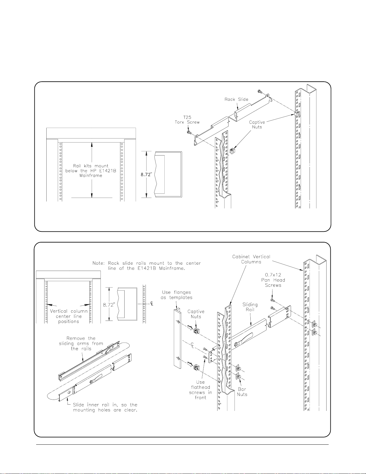
Mounting the Rails
or Rack Slides
Figures 1-1 2 and 1-13 sho w how to mo unt th e rails or rack sl ides in th e ra ck.
Figure 1-12. Mounting the E3665A Rail Kit
Figure 1-13. Mounting the Rack Slide Kit
HP E1421B User Information Using the Mainframe 19
Page 20
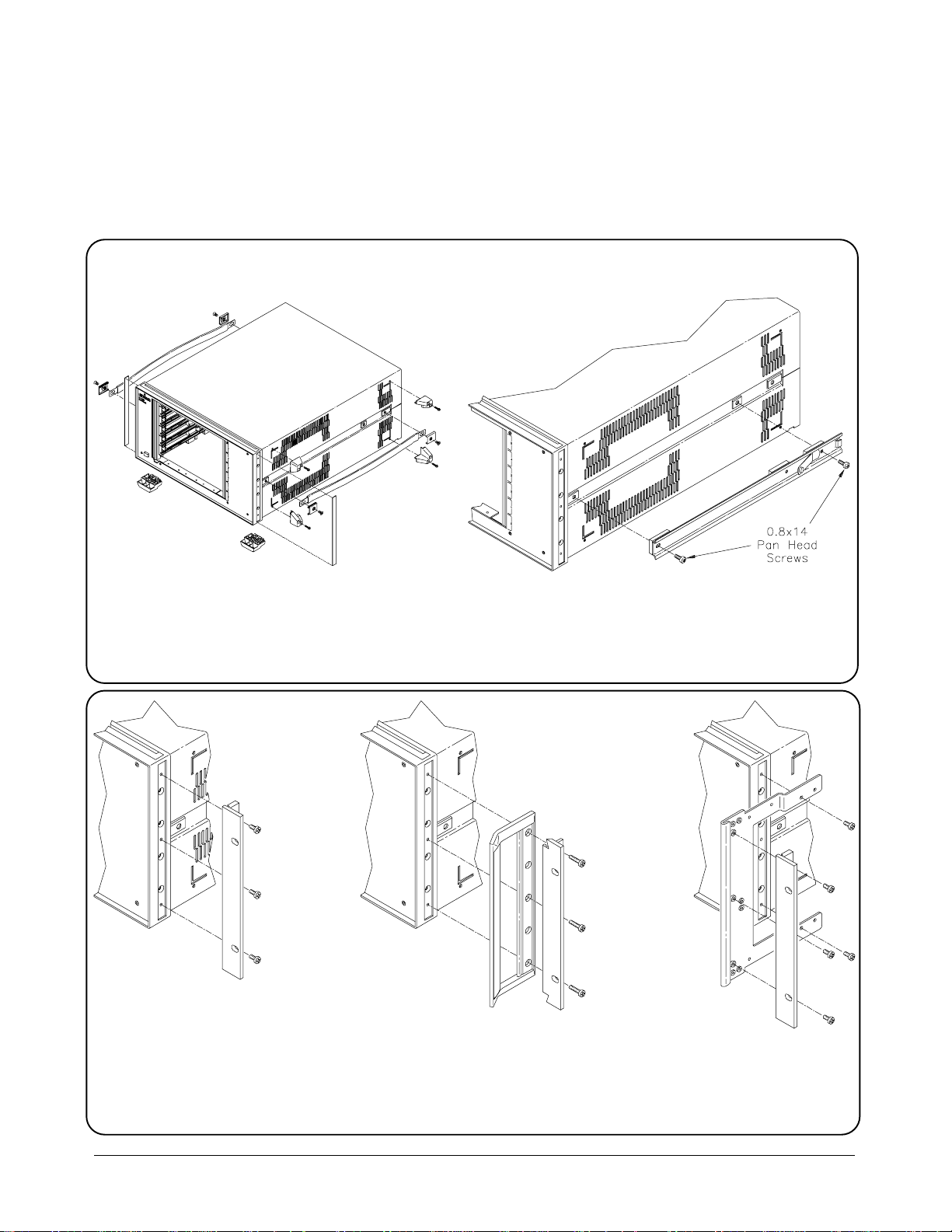
Preparing the
Mainframe
Remove these
parts to rack mount
the mainframe.
Figure 1-14 shows the steps that are needed to prepare the mainframe for
rack mounting. Figure 1-15 sh ows how to attach the Option Kit s to the
mainframe.
Note: This step is only for the Rack Slide Kit.
Figure 1-14. Preparing the Mainframe
Option 908 Flush Mount Option 909 Flush Mount Option 916 Recessed Mount
with Handles
Figure 1-15. Installing the Option Kits.
20 Using the Mainframe HP E1421B User Information
Page 21
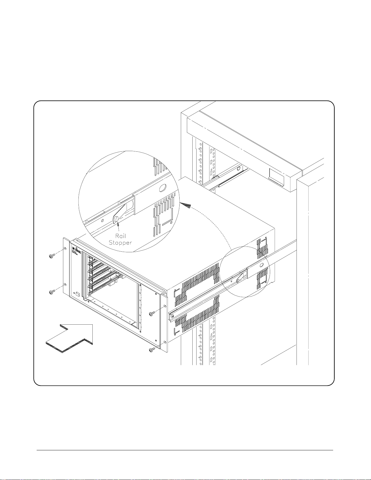
Installing the
mainframe
Note: Be sure that Rail
Stopper is aligned with hole
in Rack Slide. If not, switch
the right and left Rack Slides.
Figure 1-16 shows the final step to install the mainframe into the rack. Be
sure to connect the mainframe power cord to the rack power supply. Figure
1-16 is shown with Option 908 Flush M ount Kit and the Rack Slide Kit.
Figure 1-16. Installing the Mainframe in the Rack
HP E1421B User Information Using the Mainframe 21
Page 22

Intermodule
Chassis
Shield Kit
The Intermodule Chassis Shield Kit (HP Part Number E140 9B) is the HP
implementation of the VX Ibus specification that allows grou nded shi elding
between mainframe slots. Figure 1-17 shows how to install the E1409B in
the E1421B mainframe. The E1409B can be ordered from your nearest
Hewlett-Packard Sales and Support Office.
Note: Chassis Shield Guides must
be used to ensure proper grounding
of the Chassis Shield. Do not slide
the Chassis Shield into the
mainframe without the Guides.
Figure 1-17. Installing Intermod ule Chassis Shi eld Kit
22 Using the Mainframe HP E1421B User Information
Page 23

Chapter 2
Replaceable Parts & Assemblies
There are no user servicable parts in the HP E1421B. Repair is limited to
replacing the power supply module, the backplane modu le, or other
mechanical parts only.
Module
Replacement
The power supply is available on an exchange basis. The backplane
assembly should be replaced and not repaired (no exchange required on the
backplane).
Power Su pply E14 01-69202
Backplane E14 21-67500
Component Locator Refer to Figures 2-1 and 2-2 for component locator information.
WARNING There are no user servic abl e parts in the HP E1421B. Refer
repair and servicing to trained service personnel.
AVERTISSEMENT Ne contient pas d’èlèm ent que l’utilisateur puiss e rèpa re r.
Confier les rèparations et la maintenance à un technicien
qualifiè.
Cleaning Fan Filters The HP E1421B does no t have any fan filters. Therefore it is not necessary
to remove, clean, or replace the filters.
HP E1421B User Information Replaceable Parts & Assemblies 23
Page 24

HP E1421B Replaceable Parts List
Reference
Designator
A1
A2
B1-B2
PNL1
CBL2
CBL3
CR1
CVR1
F1 2110-0054 1 FUSE 15A, 250V NTD FE UL 75915 314015
MP94
MP98
MP103-114
MP130
MP135-MP136
MP137
MP138-MP141
MP142
MP143-MP146
MP149
MP150
HP Part
Number
E1421-675 00
E1401-692 02
3160-086 4
E1421-04300
E1401-616 12
E1401-616 10
1990-102 7
E1421-041 10
1400-150 2
E1421-812 06
E1421-812 06
E1421-001 02
E1421-001 03
E1421-046 02
E1401-412 02
E1401-002 03
5001-054 1
5021-840 7
5041-880 1
5041-880 2
5041-882 1
E1421-812 04
E1421-812 05
E1421-212 00
E1421-212 01
Total
Qty.
1
1
2
1
1
1
1
1
1
3
3
1
1
1
12
1
2
1
4
1
8
1
1
2
2
Description Mfr.
PC ASSY BACKPLANE/INTERFACE
POWER SUPPLY 650W
FAN - TBAX; 12V DC
PANEL FRONT
CABLE - PWR SWITCH LED
CABLE - FAN
LED - LMP
COVER TOP
CLIP - LED T - 1
RAILS VERTICAL
RAILS VERTICAL
CHASSIS MAIN
CHASSIS TOP
PLENUM AIR
CARD GUIDE
BLANK PANEL (Fan Carrier)
TRIM, SIDE
FRAME, FM, FRONT
FOOT, MOLD
TRIM TOP
STNDF - REAR PNL
RAIL FRONT LEFT
RAIL FRONT RIGH T
NUT BARS FRONT
NUT BARS REAR
Code
28480
28480
28480
28480
28480
28480
28480
28480
28480
28480
28480
28480
28480
28480
28480
28480
28480
28480
28480
28480
28480
28480
28480
28480
28480
Mfr. Part
Number
E1421-67500
E1401-69202
3160-0864
E1421-04300
E1401-61612
E1401-61610
1990-1027
E1421-04110
1400-1502
E1421-81206
E1421-81206
E1421-00102
E1421-00103
E1421-04602
E1401-41202
E1401-00203
5501-0541
5021-8407
5041-8801
5041-8802
5041-8821
E1421-81204
E1421-81205
E1421-21200
E1421-21201
MP1
MP2
MP3
PNL2-PNL3
PNL5
X1 2110-0565 1 FUSEHOLDER CAP 15A MAX 28480 2110-0565
5041-881 9
5062-370 4
54710-62 50 1
E1400-002 09
E1400-002 03
2
2
2
2
1
CAP - STRP HDL FRT
STRAP HDL 18 IN
CAP STRAP HANDLE
FILLER PANEL ONE SLOT
FILLER PNL - 3 SLOT
28480
28480
28480
28480
28480
5041-8819
5062-3704
54710-62501
E1400-00209
E1400-00203
24 Replaceable Parts & Assemblies HP E1421B User Information
Page 25
Figure 2-1. Mainframe Replaceable Parts
HP E1421B User Information Replaceable Parts & Assemblies 25
Page 26

Figure 2-2. Fan & Rear Panel Replaceable Parts
26 Replaceable Parts & Assemblies HP E1421B User Information
Page 27

Specifications
The HP E1421B mainframes are 100% compatible with VXIbus
specification revision 1.4.
Overall Mainframe Size
Mainframe Weight HP E1421B: 15.0 Kg (33.0 lbs) with no modules ins talled.
Appendix A
Module Size Six (6) C-Size slots. The mainframes also ac cept A- or B- Size modules
using the optional HP E1403 Module Carrier.
Input Power 50 - 60 Hz Input Power:
Automatic Voltage Ranging, nominal range: 100 - 240 Vac
Nominal Frequency Range:50 - 60 Hz
400 Hz Input Power:
Nominal Voltage Range: 100 - 120 VAC
Nominal Frequency: 400 Hz
DC Input Power:
Input Voltage Range: 100 VDC min imu m - 370 VDC max imu m
General Power Supply Power Factor Corrected
Power Switch: On/Standby with lighted indicator in front.
Inrush Current: 40A max
Designed to meet EN-60555-2
Socket for detachable line cord: IEC 320 "HOT"
Chassis ground tap on rear panel: M4 x 0.7 threaded insert.
±10%
±10%
±10%
±10%
HP E1421B User Information 27
Page 28

Fuse:
Power Supply Outputs
Voltage Maximum
Fuse
Current
100Vac
120Vac
220-240Vac
15A
12A
8A
DC Output Voltage Peak DC Output
Current (IMP*)
15AF
15AF
15AF
P-P Dynamic
Current (IMD**)
55 °C
+5V
+12V
-12V
+24V
-24V
-5.2V
-2V
45A
8A
8A
8A
8A
40A
15A
5.0A
2.5A
2.5A
4.0A
4.0A
5.0A
3.5A
* IMP = Rated mainframe peak DC output current as defined by the
VXIbus Specification.
** IMD = Rated mainframe peak-to-peak dynamic current as defined in the
VXIbus Specification by a
current vs. frequency curve.
VXI Ripple/Noise*
DC Output
Voltage
+5V
+12V
-12V
+24V
-24V
-5.2V
-2V
* Per VXI Specification rev. 1.4
Allowed
Variation
+0.25/-0.125
+0.06/-0.36
-0.60/+0.36
+1.2/-0.72
-1.2/+0.72
-0.26/+0.156
-0.10/+0.10
Humidity Up to 65% relative humidity from 0 to 40 °C
Temperature Range Non-operating:-40 ºC to +75 ºC
Operating: 0ºC to 55 ºC
Max. DC
Load
Ripple/Noise
50 mV
50 mV
50 mV
150 mV
150 mV
50 mV
50 mV
Max. Induced
Ripple/Noise
50 mV
50 mV
50 mV
150 mV
150 mV
50 mV
50 mV
28 HP E1421B User Information
Page 29

Shock Operating, Functional:
Vibration End use, Handlin g:
Cooling Provided
2
Random: 0.0001 g
Survival:
Swept Sine: 5-500 Hz resonant search, 1 Octave/min sweep rate, 5 min
dwell at resonance.
Random: 0.015 g
Less than 45.5 kg: Half sine waveform, <3ms duration, velocity change
depending on weight.
Greater than 45.5 kg: 10.2 cm free fall tilt drop.
Transportation:
Trapezoidal waveform, velocity change dependent on weight, minimum
acceleration 30 g.
/Hz, 5-500 Hz, ~0.21 Grms, 10 min/axi s.
2
/Hz, 5-500 Hz, ~2.0 9 Grms, 10 mi n/axis .
HP E1421B Minimum Airflow Availabl e per Slot
Fan set to "Variable": Quiet operation (appro x. 75% airflo w) at <30 ºC
ambient temperature and high speed operation at >40 ºC ambient
temperature.
Fan set to "HIGH": Full airflow all the time.
For modules with typi cal density:
10 ºC rise at 60W per slot
15 ºC rise at 75W per slot
Acousti cal Nois e Low fan speed: 53 dBA sound pressure at byst and er positi on.
Lpa = 53 dB fiktiver Arbeitsplatz, normalier Betrieb, nach DIN 45635 T.1
High fan speed: 59 dBA sound pressure at bystander position.
Lpa = 59 dB fiktiver Arbeitsplatz, normalier Betrieb, nach DIN 45635 T.1
HP E1421B User Information 29
Page 30

EMC Testing Meets requirements of CISPR 11 Level A.
Module Weight Maximum 3.5 Kg (7.7 lbs) per slot to comply with vibration and shock
specifications. Heavier modules may be installed if vibration and shock
environment is less severe.
Safety IEC 348, UL 1244, and CSA C22.2 #231 .
30 HP E1421B User Information
 Loading...