

High-Performance VXI
Universal Counter
Agilent E1420B
Data Sheet
•
1-Slot, C-size, message based
•
200 MHz frequency range, optional 2.5 GHz channel
•
9-digit resolution in 1 second gate time
•
2 ns time interval resolution (200 ps with averaging)
•
Shared memory option configuration
•
Phase measurement and measurement timeout
Description
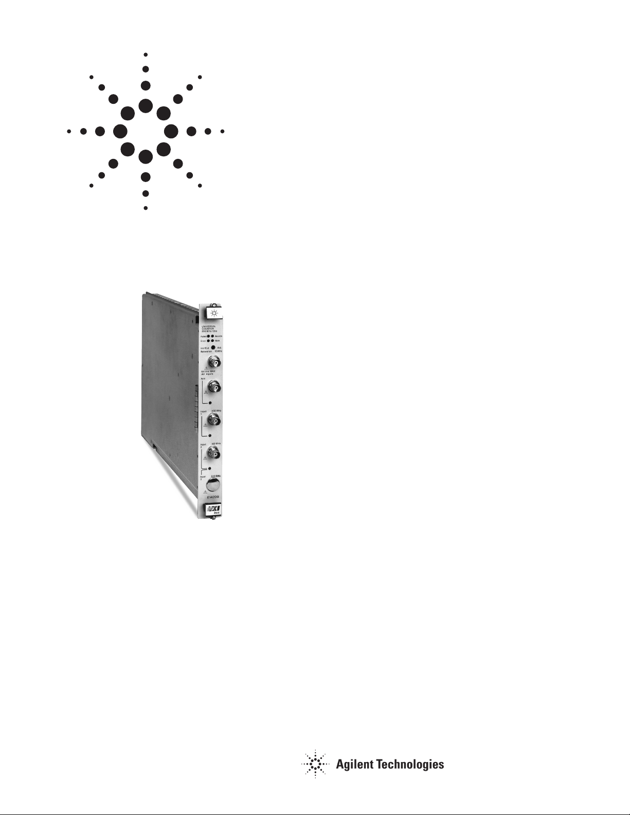
The Agilent Technologies E1420B High-Performance
Universal Counter is a C-size, 1-slot, message-based VXI
module. It provides the full set of traditional universal
counter measurements (frequency, period, time interval,
totalize, and ratio), plus the automatic measurements of
rise/fall time, pulse width, phase, and ac/dc voltages.
Additionally, this module provides x10 attenuation, allowing
measurements of higher-powered signals.
Agilent E1420B
The E1420B is ideal for today’s ATE applications requiring
high speed in all phases of a measurement — setup, measure,
and output. It can make up to 60 measurements per second
of the same function. It can also sequence through a series
of different functions at up to 40 measurements per second.
For even faster measurements, the optional shared memory
capability yields up to 160 measurements per second. This
shared RAM option allows the E1420B to send measurement
data to a VXI device with shared RAM. Data may be
accessed by the controller, thus eliminating data formatting
time and providing higher measurement throughput.
The E1420B features the industry standard SCPI interface
language. SCPI will let you develop code that can easily be
leveraged, increase the life of test software, and decrease
the time spent learning new instrument languages.
Refer to the Agilent Technologies Website for instrument
driver availability and downloading instructions, as well as
for recent product updates, if applicable.

Outstanding Resolution and Range
The E1420B offers a 200 MHz frequency range (2.5 GHz with
option 030) and 2 ns time interval resolution (200 ps with
averaging). Rise and fall times can be measured
automatically down to 15 ns.
Improve the System Clock Without Sacrificing Mainframe
Space
An optional highly stable TCXO time-base is available for
the E1420B. By externally driving the VXI system clock
(CLK10) with this TCXO, you can substantially reduce
system clock errors without losing valuable mainframe
slots. This option improves measurement repeatability and
accuracy.
Measurement Timing Control
For synchronizing your measurement to an external event,
such as an RF burst, VXIbus and external triggering are
available.
Programmable measurement time-outs help you optimize
system performance even if the input signal is absent.
Single Measurement Auto-Trigger Speeds Measurements
Repetitive auto-trigger measurements are faster than ever
with the E1420B’s single measurement auto-trigger. This
feature analyzes the input signal only once, setting the
trigger levels, and speeding through the rest of the
measurements.
Adjustable Sensitivity
Measuring low-level signals isn’t a problem: the
Agilent E1420B features 35 mV rms sensitivity to 200 MHz.
When noise is a problem, this sensitivity can be decreased to
100 mV rms by using hysteresis control.
Optional 2.5 GHz Channel (Input 3)
Increase your frequency range to 2.5 GHz for
communications and navigation applications.
Save on Software Costs with SCPI
The E1420B features the industry standard SCPI interface
language. SCPI will let you develop code that can easily be
leveraged, increase the life of test software, and decrease
the time spent learning new instrument languages. SCPI
also simplifies the use of the counter; for example, you can
set a trigger level using a percentage of signal amplitude.
Option 100
Option 100 is a mandatory no-cost option that must be
ordered with the E1420B. Option 100 reduces the maximum
TI Delay range from 99.999 seconds to 1 second.
Product Specifications
Functions
Period: Yes
Time interval: Yes
Totalize: Yes
Gated totalize: Yes
Ratio: Yes
Pulse width: Yes
Rise/fall time: Yes
Phase: Yes
Vdc: Yes
Vac: Yes
Up/down counter: No
Measurements
Frequency: 200 MHz (standard) 2.5 GHz (with
Frequency 1, 2, 3:
Range: 0.001 Hz to 200 MHz, input 1;
Resolution: 9 digits/s of measurement time +
Period 1, 2, 3:
Range: 5 ns to 1,000 s, input 1;
Resolution: Same as Frequency
Time interval (TI) 1 to 2:
Range: 1 ns to 1,000 s
Resolution: 2 ns + trigger error, single-shot;
Rise/fall time 1:*
Range: 15 ns to 400 µsec
Resolution: Same as TI
Pulse width 1, 2:*
Range: 5 ns to 1 ms
Resolution: Same as TI
Phase 1 relative 2:*
Range: 0.1° to 360°
Resolution: TI resolution x frequency x 360°
Ratio 1/2, 2/1, 3/1:
Range (1/2, 2/1): 0.001 Hz to 100 MHz
Range (3/1): 90 MHz to 2.5 GHz (Optional)
Totalize 1, 1 by 2, 2 by 1:
Range: 0 to (1 x 1.0E12 - 1) events
Min/max, ac voltage 1, 2:*
Range: 200 mVp-p to 5 Vp-p
Resolution: 30 mV
Min/max, dc voltage 1:
Range: 30 mV to ±10 V
Resolution: 30 mV
*Frequency range 1 kHz to 20 MHz.
option)
0.001 Hz to 100 MHz, input 2;
90 MHz to 2.5 GHz, input 3 (Optional)
trigger error + system jitter
(Frequency resolution is directly
proportional to gate time. For
example, resolution is 9 digits for a
1-second gate time and 8 digits for a
0.1-second gate time.)
10 ns to 1000 s, input 2;
400 ps to 10 ns, input 3 (Optional)
1 ns to 10 s
average)
200 ps + trigger error, averaging
sec
(manual)
(single-shot);
(averaging) (100-gate
(automatic)
(x Atten.)
(x Atten.)
(x Atten.)
; to 800
(x Atten.)
2

Input Characteristics for Channels 1, 2
Sinewave sensitivity: 35 mV rms
Pulse sensitivity: 100 mVp-p
(with minimum pulse
width of 5 ns)
Dynamic range: 200 mVp-p to 5 Vp-p
Attenuator: x1
Signal operating range: ± 10 V
(default)
(x Atten.) (1 MΩ)
or x10
(x Atten.)
; ± 5 V
(50
Ohm)
Trigger level range: ± 10.2 V with step size of 2.5 mV
(Specified by V or % of signal)
Trigger level accuracy: ± 30 mV
Coupling: ac/dc
Impedance: 50 Ω/1 MΩ (default programmable)
Slopes: Positive or Negative
Input: Separate or Common
General Characteristics
Gate time: 1 ms to 99.99s in 1 ms steps
External arm: via front-panel BNC or VXI TTL TRIG
Auto trigger:
Range: 1 kHz to 20 MHz (Single or Repetitive
Minimum amplitude: 200 mVp-p
TI delay (inserts delay after start
event before allowing stop event to
occur):
Range (Option 100*): 1 ms to 1 s in 1 ms step
Measurement timeout: 0.1 s to 1,500 s
Gate output: VXI TTLTRIP Lines
Measurement throughput rate
(measured using Radisys EPC-2):
Free-run: Up to 60 Measurements/s
Switching: Up to 40 Measurements/s
Shared memory (option 040): Up to 160 Measurements/s
Memory states: 10 setups can be stored and recalled
*Note: Option 100 is a mandatory no-cost option that must be ordered with the E1420B.
Option 100 reduces the maximum TI Delay range from 99.999 seconds to 1 second.
Time Base
Standard: VXI CLK10
Option 010 TCXO time base:
Frequency: 10 MHz
Aging: <0.1 ppm/month
Temperature: ± 1 ppm, 0 to 40° C
UHF Channel (Input 3)
(Option 030)
Frequency range: 90 MHz to 2.5 GHz
Sensitivity (sinewave):
90 MHz-1 GHz: –25 dBm
1 GHz-1.8 GHz: –20 dBm
1.8 GHz-2.5 GHz: –12 dBm
level
lines
Range)
(Volatile)
(x Atten.)
(x Attn.)
± 1% of trigger
(1 routed to 2)
Shared Memory
(Option 040)
Shared memory throughput rate:
Up to 160 Measurements/s
General Specifications
VXI Characteristics
VXI device type: Message based
Size: C
Slots: 1
Connectors: P1/2
Shared memory: Yes
VXI buses: TTL Trigger Bus
Instrument Drivers - See the Agilent Technologies Website
(http://www.agilent.com/find/inst_drivers) for driver availability and
downloading.
Command module firmware: n/a
Command module firmware rev: n/a
I-SCPI Win 3.1: n/a
I-SCPI Series 700: n/a
C-SCPI LynxOS: n/a
C-SCPI Series 700: n/a
Panel Drivers: Yes
VXI
plug&play
VXI
plug&play
VXI
plug&play
Module Current
+5 V: 2 0.15
+12 V: 0.25 0.01
–12 V: 0.15 0.02
+24 V: 00
–24 V: 00
–5.2 V 0.8 0.03
–2 V: 00
Cooling/Slot
Watts/slot: 15.50
∆P mm H
Air Flow liter/s: 1.00
Win Framework: Yes
Win 95/NT Framework: Yes
HP-UX Framework: No
O: 0.15
2
I
PM
I
DM
Ordering Information
Description Product No.
High-Performance VXI Universal Counter E1420B*
TCXO Time Base E1420B 010
UHF Input Channel E1420B 030
High Throughput/Shared RAM E1420B 040
Reduced TI Delay Spec E1420B 100
Operation Manual E1420B 0B2
Service Manual E1420B 0B3
*Note: You must order Option 100.
3

Agilent Technologies’
Test and Measurement Support,
Services, and Assistance
Agilent Technologies aims to maximize the value you receive, while
minimizing your risk and problems. We strive to ensure that you get the test
and measurement capabilities you paid for and obtain the support you need.
Our extensive support resources and services can help you choose the right
Agilent products for your applications and apply them successfully. Every
instrument and system we sell has a global warranty. Support is available
for at least five years beyond the production life of the product. Two
concepts underlie Agilent’s overall support policy: "Our Promise" and "Your
Advantage."
Our Promise
Our Promise means your Agilent test and measurement equipment will
meet its advertised performance and functionality. When you are choosing
new equipment, we will help you with product information, including
realistic performance specifications and practical recommendations from
experienced test engineers. When you use Agilent equipment, we can verify
that it works properly, help with product operation, and provide basic
measurement assistance for the use of specified capabilities, at no extra
cost upon request. Many self-help tools are available.
Your Advantage
Your Advantage means that Agilent offers a wide range of additional expert
test and measurement services, which you can purchase according to your
unique technical and business needs. Solve problems efficiently and gain a
competitive edge by contracting with us for calibration, extra-cost upgrades,
out-of-warranty repairs, and on-site education and training, as well as
design, system integration, project management, and other professional
engineering services. Experienced Agilent engineers and technicians
worldwide can help you maximize your productivity, optimize the return on
investment of your Agilent instruments and systems, and obtain dependable
measurement accuracy for the life of those products.
By internet, phone, or fax, get assistance with all your test &
measurement needs.
Online assistance:
www.agilent.com/find/assist
Phone or Fax
United States:
(tel) 1 800 452 4844
Canada:
(tel) 1 877 894 4414
(fax) (905) 282 6495
China:
(tel) 800 810 0189
(fax) 1 0800 650 0121
Europe:
(tel) (31 20) 547 2323
(fax) (31 20) 547 2390
Japan:
(tel) (81) 426 56 7832
(fax) (81) 426 56 7840
Korea:
(tel) (82 2) 2004 5004
(fax) (82 2) 2004 5115
Latin America:
(tel) (305) 269 7500
(fax) (305) 269 7599
Taiwan:
(tel) 080 004 7866
(fax) (886 2) 2545 6723
Other Asia Pacific Countries:
(tel) (65) 375 8100
(fax) (65) 836 0252
Email: tm_asia@agilent.com
Product specifications and descriptions in this document subject to change
without notice.
© Agilent Technologies, Inc. 2002
Printed in USA January 1, 2002
5965-5548E
 Loading...