


Agilent E1326B/E1411B 5 1/2 Digit Multimeter
User’s Manual
E1326-90009
Printed in USA
July 2004 E0704
*E1326-90009*
S1

Contents
HP E1326B/E1411B 5 1/2 Digit Multimeter User’s Manual
Warranty . . . . . . . . . . . . . . . . . . . . . . . . . . . . . . . . . . . . . . . . . . 7
WARNINGS . . . . . . . . . . . . . . . . . . . . . . . . . . . . . . . . . . . . . . . . 8
Safety Symb ols . . . . . . . . . . . . . . . . . . . . . . . . . . . . . . . . . . . . . . 8
Declaration of Conformity . . . . . . . . . . . . . . . . . . . . . . . . . . . . . . . . . 9
Declaration of Conformity . . . . . . . . . . . . . . . . . . . . . . . . . . . . . . . . . 10
Reader Comment Sheet . . . . . . . . . . . . . . . . . . . . . . . . . . . . . . . . . . 11
Chapter 1. Getti n g Started with the HP E1 326B/E1411B Multim e ter . . . . . . . . . . . 13
About This Chapter . . . . . . . . . . . . . . . . . . . . . . . . . . . . . . . . . . . . 13
Multimeter Overview . . . . . . . . . . . . . . . . . . . . . . . . . . . . . . . . . . . 13
Function al Description . . . . . . . . . . . . . . . . . . . . . . . . . . . . . . . . 14
Electrical Description . . . . . . . . . . . . . . . . . . . . . . . . . . . . . . . . . 14
Physical Description . . . . . . . . . . . . . . . . . . . . . . . . . . . . . . . . . 15
Introduction to Operation . . . . . . . . . . . . . . . . . . . . . . . . . . . . . . . . . 16
Multimeter Self-Test . . . . . . . . . . . . . . . . . . . . . . . . . . . . . . . . . 16
Resetting the Multimeter . . . . . . . . . . . . . . . . . . . . . . . . . . . . . . . 17
Making a Measurement . . . . . . . . . . . . . . . . . . . . . . . . . . . . . . . . 20
Chapter 2. Configu r i n g the HP E1326B/E1411B Mul ti m e ter . . . . . . . . . . . . . . . . 21
About This Chapter . . . . . . . . . . . . . . . . . . . . . . . . . . . . . . . . . . . . 21
Installation Overview . . . . . . . . . . . . . . . . . . . . . . . . . . . . . . . . . . . 21
Setting the Logical Address Switch . . . . . . . . . . . . . . . . . . . . . . . . . 22
VXIbus Interrupt Lines . . . . . . . . . . . . . . . . . . . . . . . . . . . . . . . . 24
HP E1326B Internal Installation . . . . . . . . . . . . . . . . . . . . . . . . . . . 25
Installing the HP E1411B in a Mainframe . . . . . . . . . . . . . . . . . . . . . . 26
The Reference Frequency . . . . . . . . . . . . . . . . . . . . . . . . . . . . . . . 27
Input Characteristics . . . . . . . . . . . . . . . . . . . . . . . . . . . . . . . . . . . . 28
Input Terminals . . . . . . . . . . . . . . . . . . . . . . . . . . . . . . . . . . . . 29
Connecting Multiplexers . . . . . . . . . . . . . . . . . . . . . . . . . . . . . . . 30
Connecting Input Signals . . . . . . . . . . . . . . . . . . . . . . . . . . . . . . . . . 32
Wiring Considerations . . . . . . . . . . . . . . . . . . . . . . . . . . . . . . . . 32
Measurement Connections . . . . . . . . . . . . . . . . . . . . . . . . . . . . . . 33
Carrier Cable Assemblies . . . . . . . . . . . . . . . . . . . . . . . . . . . . . . . . . 37
Additional Configurations . . . . . . . . . . . . . . . . . . . . . . . . . . . . . . . . . 39
Selecting VME RAM . . . . . . . . . . . . . . . . . . . . . . . . . . . . . . . . . 39
Disabling Front-panel for Stand-alone Applications . . . . . . . . . . . . . . . . . 39
Chapter 3. Using the HP E1326B/E1411B Mul tim eter . . . . . . . . . . . . . . . . . . . . 41
About This Chapter . . . . . . . . . . . . . . . . . . . . . . . . . . . . . . . . . . . . 41
Using the Pr ograms . . . . . . . . . . . . . . . . . . . . . . . . . . . . . . . . . . 41
Making a Single Measurement . . . . . . . . . . . . . . . . . . . . . . . . . . . . . . 42
Making a Burst of Measurements . . . . . . . . . . . . . . . . . . . . . . . . . . . . . 43
Making an Externally Triggered Burst of Measurements . . . . . . . . . . . . . . . . . 44
HP E1326B/E1411B 5 1/2 Digit Multimeter User’s Manual Contents 1

Making Multiple Burst Measurements . . . . . . . . . . . . . . . . . . . . . . . . . . 45
Scanning a Channel List . . . . . . . . . . . . . . . . . . . . . . . . . . . . . . . . . . 46
Making Multiple Scans . . . . . . . . . . . . . . . . . . . . . . . . . . . . . . . . . . 47
Making Multiple Paced Scans . . . . . . . . . . . . . . . . . . . . . . . . . . . . . . . 48
Making an Externally Triggered Scan . . . . . . . . . . . . . . . . . . . . . . . . . . . 49
Scanning Sw itchbox Channels (E1326B/E1351A) . . . . . . . . . . . . . . . . . . . . 50
Scanning Sw itchbox Channels (E1411B/E1460A) . . . . . . . . . . . . . . . . . . . . 52
Multiple High-Speed Scans . . . . . . . . . . . . . . . . . . . . . . . . . . . . . . . . 54
Maximizing Measurement Speed . . . . . . . . . . . . . . . . . . . . . . . . . . . . . 56
Changing the Data Format . . . . . . . . . . . . . . . . . . . . . . . . . . . . . . . . . 58
Using a PC, C Language, and the HP 82335 HP-IB Interface Card . . . . . . . . . . . 60
Maximizing Measurement Accuracy . . . . . . . . . . . . . . . . . . . . . . . . . . . 63
Storing Readings in Shared Memory . . . . . . . . . . . . . . . . . . . . . . . . . . . 64
Checking for Errors . . . . . . . . . . . . . . . . . . . . . . . . . . . . . . . . . . . . 66
Synchronizing the Multimeter with a Computer . . . . . . . . . . . . . . . . . . . . . 68
Additional Measurement Functions . . . . . . . . . . . . . . . . . . . . . . . . . . . . 69
Chapter 4. Understanding the HP E1326B/E1411B Multimeter . . . . . . . . . . . . . . . 75
About This Chapter . . . . . . . . . . . . . . . . . . . . . . . . . . . . . . . . . . . . 75
Using MEASure and CONFigure Commands . . . . . . . . . . . . . . . . . . . . . . 76
How to Make Measurements . . . . . . . . . . . . . . . . . . . . . . . . . . . . . . . 78
Using MEASure . . . . . . . . . . . . . . . . . . . . . . . . . . . . . . . . . . . 78
Using CONFigure . . . . . . . . . . . . . . . . . . . . . . . . . . . . . . . . . . . 78
Data Formats and Destinations . . . . . . . . . . . . . . . . . . . . . . . . . . . . . . 80
Data Formats . . . . . . . . . . . . . . . . . . . . . . . . . . . . . . . . . . . . . 80
Reading Destinations . . . . . . . . . . . . . . . . . . . . . . . . . . . . . . . . . 81
Reading Des tination Summary . . . . . . . . . . . . . . . . . . . . . . . . . . . . 85
Measurement Functions . . . . . . . . . . . . . . . . . . . . . . . . . . . . . . . . . . 86
DC Voltage Measurements . . . . . . . . . . . . . . . . . . . . . . . . . . . . . . 86
RMS AC Voltage Measurements . . . . . . . . . . . . . . . . . . . . . . . . . . . 86
Resistance Measurements . . . . . . . . . . . . . . . . . . . . . . . . . . . . . . . 87
Temperature Measurements . . . . . . . . . . . . . . . . . . . . . . . . . . . . . 88
Specifying a Function . . . . . . . . . . . . . . . . . . . . . . . . . . . . . . . . . 90
Multimeter Parameters . . . . . . . . . . . . . . . . . . . . . . . . . . . . . . . . . . . 91
Range . . . . . . . . . . . . . . . . . . . . . . . . . . . . . . . . . . . . . . . . . 93
Autorange . . . . . . . . . . . . . . . . . . . . . . . . . . . . . . . . . . . . . . . 94
Resolution . . . . . . . . . . . . . . . . . . . . . . . . . . . . . . . . . . . . . . . 95
Aperture and Integration Time . . . . . . . . . . . . . . . . . . . . . . . . . . . . 97
Autozero . . . . . . . . . . . . . . . . . . . . . . . . . . . . . . . . . . . . . . . 99
Offset Compensation . . . . . . . . . . . . . . . . . . . . . . . . . . . . . . . . . 100
Triggering the Multimeter . . . . . . . . . . . . . . . . . . . . . . . . . . . . . . . . . 101
The Trigger Source . . . . . . . . . . . . . . . . . . . . . . . . . . . . . . . . . . 103
The Trigger Count . . . . . . . . . . . . . . . . . . . . . . . . . . . . . . . . . . 104
The Trigger Delay . . . . . . . . . . . . . . . . . . . . . . . . . . . . . . . . . . 106
The Sample Count . . . . . . . . . . . . . . . . . . . . . . . . . . . . . . . . . . 108
The Sample Period . . . . . . . . . . . . . . . . . . . . . . . . . . . . . . . . . . 109
The Wait-For-Trigger State . . . . . . . . . . . . . . . . . . . . . . . . . . . . . . 111
Using a Sing le Trigger . . . . . . . . . . . . . . . . . . . . . . . . . . . . . . . . 112
Aborting a Measurement . . . . . . . . . . . . . . . . . . . . . . . . . . . . . . . 112
2 Contents HP E1326B/E1411B 5 1/2 Digit Multimeter User’s Manual

Saving Multimeter Configurations . . . . . . . . . . . . . . . . . . . . . . . . . . . . 114
How to Save and Recall a Configuration . . . . . . . . . . . . . . . . . . . . . . . 114
Chapter 5. HP E1326B/E1411B Multimeter Command Reference . . . . . . . . . . . . . 117
Using This Chapter . . . . . . . . . . . . . . . . . . . . . . . . . . . . . . . . . . . . 117
Command Types . . . . . . . . . . . . . . . . . . . . . . . . . . . . . . . . . . . . . . 117
Common Command Format . . . . . . . . . . . . . . . . . . . . . . . . . . . . . 117
SCPI Command Format . . . . . . . . . . . . . . . . . . . . . . . . . . . . . . . 117
Linking Commands . . . . . . . . . . . . . . . . . . . . . . . . . . . . . . . . . . 119
SCPI Comman d Reference . . . . . . . . . . . . . . . . . . . . . . . . . . . . . . . . 121
ABORt . . . . . . . . . . . . . . . . . . . . . . . . . . . . . . . . . . . . . . . . . . . 122
CALibration . . . . . . . . . . . . . . . . . . . . . . . . . . . . . . . . . . . . . . . . 123
:LFRequency . . . . . . . . . . . . . . . . . . . . . . . . . . . . . . . . . . . . . 123
:LFRequency? . . . . . . . . . . . . . . . . . . . . . . . . . . . . . . . . . . . . . 123
:ZERO:AUTO . . . . . . . . . . . . . . . . . . . . . . . . . . . . . . . . . . . . 124
:ZERO:AUTO? . . . . . . . . . . . . . . . . . . . . . . . . . . . . . . . . . . . . 124
CONFigure . . . . . . . . . . . . . . . . . . . . . . . . . . . . . . . . . . . . . . . . . 126
:FRESistance . . . . . . . . . . . . . . . . . . . . . . . . . . . . . . . . . . . . . 127
:RESistance . . . . . . . . . . . . . . . . . . . . . . . . . . . . . . . . . . . . . . 128
:TEMPerature . . . . . . . . . . . . . . . . . . . . . . . . . . . . . . . . . . . . . 129
:VOLTage:AC . . . . . . . . . . . . . . . . . . . . . . . . . . . . . . . . . . . . 130
:VOLTage[:DC] . . . . . . . . . . . . . . . . . . . . . . . . . . . . . . . . . . . 132
CONFigure? . . . . . . . . . . . . . . . . . . . . . . . . . . . . . . . . . . . . . . . . 134
DIAGnostic . . . . . . . . . . . . . . . . . . . . . . . . . . . . . . . . . . . . . . . . 135
:FETS . . . . . . . . . . . . . . . . . . . . . . . . . . . . . . . . . . . . . . . . . 135
:FETS? . . . . . . . . . . . . . . . . . . . . . . . . . . . . . . . . . . . . . . . . 135
DISPlay . . . . . . . . . . . . . . . . . . . . . . . . . . . . . . . . . . . . . . . . . . 136
:MONitor:CHANnel . . . . . . . . . . . . . . . . . . . . . . . . . . . . . . . . . 136
:MONitor:CHANnel? . . . . . . . . . . . . . . . . . . . . . . . . . . . . . . . . . 137
:MONitor[:STATe] . . . . . . . . . . . . . . . . . . . . . . . . . . . . . . . . . . 137
:MONitor[:STATe]? . . . . . . . . . . . . . . . . . . . . . . . . . . . . . . . . . 138
FETCh? . . . . . . . . . . . . . . . . . . . . . . . . . . . . . . . . . . . . . . . . . . 139
FORMat . . . . . . . . . . . . . . . . . . . . . . . . . . . . . . . . . . . . . . . . . . 140
[:DATA] . . . . . . . . . . . . . . . . . . . . . . . . . . . . . . . . . . . . . . . 140
FORMat? . . . . . . . . . . . . . . . . . . . . . . . . . . . . . . . . . . . . . . . . . . 141
INITiate . . . . . . . . . . . . . . . . . . . . . . . . . . . . . . . . . . . . . . . . . . 142
[:IMMediate] . . . . . . . . . . . . . . . . . . . . . . . . . . . . . . . . . . . . . 142
MEASure . . . . . . . . . . . . . . . . . . . . . . . . . . . . . . . . . . . . . . . . . 143
:FRESistance? . . . . . . . . . . . . . . . . . . . . . . . . . . . . . . . . . . . . . 144
:RESistance? . . . . . . . . . . . . . . . . . . . . . . . . . . . . . . . . . . . . . 145
:TEMPerature? . . . . . . . . . . . . . . . . . . . . . . . . . . . . . . . . . . . . 146
:VOLTage:AC? . . . . . . . . . . . . . . . . . . . . . . . . . . . . . . . . . . . . 147
:VOLTage[:DC]? . . . . . . . . . . . . . . . . . . . . . . . . . . . . . . . . . . . 148
MEMory . . . . . . . . . . . . . . . . . . . . . . . . . . . . . . . . . . . . . . . . . . 150
:VME:ADDRess . . . . . . . . . . . . . . . . . . . . . . . . . . . . . . . . . . . 150
:VME:ADDRess? . . . . . . . . . . . . . . . . . . . . . . . . . . . . . . . . . . . 150
:VME:SIZE . . . . . . . . . . . . . . . . . . . . . . . . . . . . . . . . . . . . . . 151
:VME:SIZE? . . . . . . . . . . . . . . . . . . . . . . . . . . . . . . . . . . . . . 151
HP E1326B/E1411B 5 1/2 Digit Multimeter User’s Manual Contents 3

:VME:STATe . . . . . . . . . . . . . . . . . . . . . . . . . . . . . . . . . . . . . 152
:VME:STATe? . . . . . . . . . . . . . . . . . . . . . . . . . . . . . . . . . . . . 152
OUTPut . . . . . . . . . . . . . . . . . . . . . . . . . . . . . . . . . . . . . . . . . . 153
:TTLTrg
:TTLTrg
READ? . . . . . . . . . . . . . . . . . . . . . . . . . . . . . . . . . . . . . . . . . . . 155
SAMPle . . . . . . . . . . . . . . . . . . . . . . . . . . . . . . . . . . . . . . . . . . 157
:COUNt . . . . . . . . . . . . . . . . . . . . . . . . . . . . . . . . . . . . . . . . 157
:COUNt? . . . . . . . . . . . . . . . . . . . . . . . . . . . . . . . . . . . . . . . 158
:SOURce . . . . . . . . . . . . . . . . . . . . . . . . . . . . . . . . . . . . . . . 158
:SOURce? . . . . . . . . . . . . . . . . . . . . . . . . . . . . . . . . . . . . . . . 159
:TIMer . . . . . . . . . . . . . . . . . . . . . . . . . . . . . . . . . . . . . . . . . 159
:TIMer? . . . . . . . . . . . . . . . . . . . . . . . . . . . . . . . . . . . . . . . . 160
[SENSe:] . . . . . . . . . . . . . . . . . . . . . . . . . . . . . . . . . . . . . . . . . . 161
FUNCtion . . . . . . . . . . . . . . . . . . . . . . . . . . . . . . . . . . . . . . . 162
FUNCtion? . . . . . . . . . . . . . . . . . . . . . . . . . . . . . . . . . . . . . . 162
RESistance:APERture . . . . . . . . . . . . . . . . . . . . . . . . . . . . . . . . 163
RESistance:APERture? . . . . . . . . . . . . . . . . . . . . . . . . . . . . . . . . 164
RESistance:NPLC . . . . . . . . . . . . . . . . . . . . . . . . . . . . . . . . . . 164
RESistance:NPLC? . . . . . . . . . . . . . . . . . . . . . . . . . . . . . . . . . . 165
RESistance:OCOMpensated . . . . . . . . . . . . . . . . . . . . . . . . . . . . . 165
RESistance: OCOMpen sated? . . . . . . . . . . . . . . . . . . . . . . . . . . . . 165
RESistance:RANGe . . . . . . . . . . . . . . . . . . . . . . . . . . . . . . . . . 166
RESistance:RANGe? . . . . . . . . . . . . . . . . . . . . . . . . . . . . . . . . . 167
RESistance:RANGe :AUTO . . . . . . . . . . . . . . . . . . . . . . . . . . . . . 167
RESistance:RANGe:AUTO? . . . . . . . . . . . . . . . . . . . . . . . . . . . . . 168
RESistance:RESolution . . . . . . . . . . . . . . . . . . . . . . . . . . . . . . . . 168
RESistance:RESolution? . . . . . . . . . . . . . . . . . . . . . . . . . . . . . . . 169
VOLTage:AC:RANGe . . . . . . . . . . . . . . . . . . . . . . . . . . . . . . . . 169
VOLTage:AC: RANGe? . . . . . . . . . . . . . . . . . . . . . . . . . . . . . . . 170
VOLTage:APERture . . . . . . . . . . . . . . . . . . . . . . . . . . . . . . . . . 171
VOLTage:APERture? . . . . . . . . . . . . . . . . . . . . . . . . . . . . . . . . 171
VOLTage[:DC]:RANGe . . . . . . . . . . . . . . . . . . . . . . . . . . . . . . . 172
VOLTage[:DC]:RANGe? . . . . . . . . . . . . . . . . . . . . . . . . . . . . . . 173
VOLTage:NPLC . . . . . . . . . . . . . . . . . . . . . . . . . . . . . . . . . . . 173
VOLTage:NPLC? . . . . . . . . . . . . . . . . . . . . . . . . . . . . . . . . . . . 174
VOLTage:RANGe:AUTO . . . . . . . . . . . . . . . . . . . . . . . . . . . . . . 174
VOLTage:RANGe:AUTO? . . . . . . . . . . . . . . . . . . . . . . . . . . . . . 175
VOLTage:R ESolution . . . . . . . . . . . . . . . . . . . . . . . . . . . . . . . . 175
VOLTage:R ESolution? . . . . . . . . . . . . . . . . . . . . . . . . . . . . . . . . 176
SYSTem . . . . . . . . . . . . . . . . . . . . . . . . . . . . . . . . . . . . . . . . . . 177
:CDEScription? . . . . . . . . . . . . . . . . . . . . . . . . . . . . . . . . . . . . 177
:CTYPe? . . . . . . . . . . . . . . . . . . . . . . . . . . . . . . . . . . . . . . . 177
:ERRor? . . . . . . . . . . . . . . . . . . . . . . . . . . . . . . . . . . . . . . . . 178
TRIGger . . . . . . . . . . . . . . . . . . . . . . . . . . . . . . . . . . . . . . . . . . 179
:COUNt . . . . . . . . . . . . . . . . . . . . . . . . . . . . . . . . . . . . . . . . 179
n[:STATe] . . . . . . . . . . . . . . . . . . . . . . . . . . . . . . . . . 153
n[:STATe]? . . . . . . . . . . . . . . . . . . . . . . . . . . . . . . . . . 154
4 Contents HP E1326B/E1411B 5 1/2 Digit Multimeter User’s Manual

:COUNt? . . . . . . . . . . . . . . . . . . . . . . . . . . . . . . . . . . . . . . . 180
:DELay . . . . . . . . . . . . . . . . . . . . . . . . . . . . . . . . . . . . . . . . 181
:DELay? . . . . . . . . . . . . . . . . . . . . . . . . . . . . . . . . . . . . . . . . 181
:DELay:AUTO . . . . . . . . . . . . . . . . . . . . . . . . . . . . . . . . . . . . 182
:DELay:AUTO? . . . . . . . . . . . . . . . . . . . . . . . . . . . . . . . . . . . 182
[:IMMediate] . . . . . . . . . . . . . . . . . . . . . . . . . . . . . . . . . . . . . 183
:SOURce . . . . . . . . . . . . . . . . . . . . . . . . . . . . . . . . . . . . . . . 183
:SOURce? . . . . . . . . . . . . . . . . . . . . . . . . . . . . . . . . . . . . . . . 184
IEEE 488.2 Common Command Reference . . . . . . . . . . . . . . . . . . . . . . . 186
Command Quick Reference . . . . . . . . . . . . . . . . . . . . . . . . . . . . . . . . 187
Appendix A. HP E1326B/E1411B Multimeter Specifications . . . . . . . . . . . . . . . . 189
General Specification s . . . . . . . . . . . . . . . . . . . . . . . . . . . . . . . . . . . 189
Appendix B. HP E1326B/E1411B Multimeter Error Messages . . . . . . . . . . . . . . . 197
Appendix C. HP E1326B/E1411B Multimeter Register-Based Programming . . . . . . . 199
About This Appendix . . . . . . . . . . . . . . . . . . . . . . . . . . . . . . . . . . . 199
Register Addressing . . . . . . . . . . . . . . . . . . . . . . . . . . . . . . . . . . . . 199
The Base Address . . . . . . . . . . . . . . . . . . . . . . . . . . . . . . . . . . . 200
Register Offset . . . . . . . . . . . . . . . . . . . . . . . . . . . . . . . . . . . . 202
Accessing the Registers . . . . . . . . . . . . . . . . . . . . . . . . . . . . . . . . 202
Register Descriptions . . . . . . . . . . . . . . . . . . . . . . . . . . . . . . . . . . . 203
The WRITE Registers . . . . . . . . . . . . . . . . . . . . . . . . . . . . . . . . 203
The Control Register . . . . . . . . . . . . . . . . . . . . . . . . . . . . . . . . . 203
The Command and Param ete r Registers . . . . . . . . . . . . . . . . . . . . . . . 204
The READ Registers . . . . . . . . . . . . . . . . . . . . . . . . . . . . . . . . . 205
The ID Register . . . . . . . . . . . . . . . . . . . . . . . . . . . . . . . . . . . . 205
The Device Ty pe Register . . . . . . . . . . . . . . . . . . . . . . . . . . . . . . 206
The Status Register . . . . . . . . . . . . . . . . . . . . . . . . . . . . . . . . . . 206
The Query Response Register . . . . . . . . . . . . . . . . . . . . . . . . . . . . 207
The Data Buffer . . . . . . . . . . . . . . . . . . . . . . . . . . . . . . . . . . . . 208
Program Timing and Execution . . . . . . . . . . . . . . . . . . . . . . . . . . . . . . 210
Resetting the Multimeter . . . . . . . . . . . . . . . . . . . . . . . . . . . . . . . 210
Configuring the Multimeter . . . . . . . . . . . . . . . . . . . . . . . . . . . . . 211
Retrieving Measurements . . . . . . . . . . . . . . . . . . . . . . . . . . . . . . . 213
Checking for Errors . . . . . . . . . . . . . . . . . . . . . . . . . . . . . . . . . . 214
Querying Parameters . . . . . . . . . . . . . . . . . . . . . . . . . . . . . . . . . 215
Using a Multiplexer with the Multimeter . . . . . . . . . . . . . . . . . . . . . . . 216
Register Triggering . . . . . . . . . . . . . . . . . . . . . . . . . . . . . . . . . . . . 217
The Trigger System . . . . . . . . . . . . . . . . . . . . . . . . . . . . . . . . . . 217
Multimeter Triggering Model . . . . . . . . . . . . . . . . . . . . . . . . . . . . 218
Control Register Sampling . . . . . . . . . . . . . . . . . . . . . . . . . . . . . . 219
Programming Examples . . . . . . . . . . . . . . . . . . . . . . . . . . . . . . . . . . 220
System Configuration . . . . . . . . . . . . . . . . . . . . . . . . . . . . . . . . . 220
Resetting the Multimeter
Reading the ID Register . . . . . . . . . . . . . . . . . . . . . . . . . . . . . . . 223
. . . . . . . . . . . . . . . . . . . . . . . . . . . . . . 221
HP E1326B/E1411B 5 1/2 Digit Multimeter User’s Manual Contents 5

Reading the Device Type Register . . . . . . . . . . . . . . . . . . . . . . . . . . 224
Reading the Query Respons e Register . . . . . . . . . . . . . . . . . . . . . . . . 22 6
Reading an Error Code . . . . . . . . . . . . . . . . . . . . . . . . . . . . . . . . 230
Stand-Alone Multimeter Measurements . . . . . . . . . . . . . . . . . . . . . . . 234
Scanning Multimeter Measurements . . . . . . . . . . . . . . . . . . . . . . . . . 246
Useful Tables . . . . . . . . . . . . . . . . . . . . . . . . . . . . . . . . . . . . . . . 262
Command and Parameter Opcodes . . . . . . . . . . . . . . . . . . . . . . . . . . 262
Register-Based Programmi ng Error Codes . . . . . . . . . . . . . . . . . . . . . . 264
Multimeter Power-On Settings . . . . . . . . . . . . . . . . . . . . . . . . . . . . 265
Function and Aperture Change Times . . . . . . . . . . . . . . . . . . . . . . . . 266
VME Interrupts . . . . . . . . . . . . . . . . . . . . . . . . . . . . . . . . . . . . 267
Appendix D. Measurement Speed and Accuracy Tradeoffs . . . . . . . . . . . . . . . . . 269
Index . . . . . . . . . . . . . . . . . . . . . . . . . . . . . . . . . . . . . . . . . . . . . . . . 279
6 Contents HP E1326B/E1411B 5 1/2 Digit Multimeter User’s Manual

Certification
Hewlett-Packard Company certifies that this product met its published specifications at the time of shipment from the factory. HewlettPackard further certifies that its calibration measurements are traceable to the United States National Institute of Standards and Technol-
ogy (formerly National Bureau of Standards), to the extent allowed by that organization’s calibration facility, and to the calibration
facilities of other International Standards Organization members.
Warranty
This Hewlett-Packard product is warranted against defects in materials and workmanship for a period of three years from date of shipment. Duration and conditions of warranty for this produc t may be superseded when the product is integr ated into (becomes a part of)
other HP products. During the warranty period, Hewlett-Packard Company will, at its option, either repair or replace products which
prove to be defective.
For warranty service or repair, this product must be returned to a service facility designated by Hewlett-Packard (HP). Buyer shal l prepay shipping charges to HP and HP shall pay shipping charges to return the product to Buyer. However, Buyer shall pay all shipping
charges, duties, and taxes for products returned to HP from another country.
HP warrants that its software and firmware designated by HP for use with a product will execute its programming instructions when
properly installed on that produ c t. HP do e s not warrant that th e oper a t io n of th e product, or softwa re , or fir m w ar e w il l be un in terru pt ed
or error free.
Limitation Of Warranty
The foregoing wa rr a nt y s ha l l not apply to defects resulting from im p roper or inadequate m a in te n a nc e by Buye r , Bu ye r- supplied products or interfacing, unauthorized modification or misuse, operation outside of the environmental specifications for the product, or improper site preparation or maintenance.
The design and implementation of any circuit on this product is the sole responsibility of the Buyer. HP does not warrant the Buyer’s
circuitry or m a lfu nc tions of HP products th a t r e sult from the Buyer’s c irc u i t r y. In add i t ion, HP does not warr ant any damage that occurs as a result of the Buyer’s circuit or any defects that result from Buyer-supplied products.
NO OTHER WARRANTY IS EXPRESSED OR IMPLIED. HP SPECIFICALLY DISCLAIMS THE IMPLIED WARRANTIES OF
MERCHANTABILITY AND FITNESS FOR A PARTICULAR PURPOSE.
Exclusive Remedies
THE REMEDIES PROVIDED HEREIN ARE BUYER’S SOLE AND EXCLUSIVE REMEDIES. HP SHALL NOT BE LIABLE
FOR ANY DIRECT, INDIRECT, SPECIAL, INCIDENTAL, OR CONSEQUENTIAL DAMAGES, WHETHER BASED ON CONTRACT, TORT, OR ANY OTHER LEGAL THEORY.
Notice
The information contained in this document is subject to change without notice. HEWLETT-PACKARD (HP) MAKES NO WARRANTY OF ANY KIND WITH REGARD TO THIS MATERIAL, INCLUDING, BUT NOT LIMITED TO, THE IMPLIED WARRANTIES OF MERCHANTABILITY AND FITNESS FOR A PARTICULAR PURPOSE. HP shall not be liable for errors contained
herein or for incidental or consequential damages in connection with the furnishing , performance or use of this material. This document contains proprietary information which is protected by copyright. All rights are reserved. No part of this document may be photocopied, reproduced, or translated to another language witho ut the prior written consent of Hewlett-Packard Company. HP assumes no
responsibility for the use or reliability of its software on equipme nt that is not furnished by HP.
U.S. Government Restricted Rights
The Software and Documentation have been developed entirely at private expense. They are delivered and licensed as "commercial
computer software" as defined in DFARS 252.227-7013 (October 1988), DFARS 252.211.7015 (May 1991) or DFARS 252.227-7014
(June 1995), as a "commercial item" as defined in FAR 2.101(a), or as "Restricted comp uter software" as defined in FAR 52.227-19
(June 1987) (or any equivalent agency regulation or contract clause), whichever is applicable. You have only those rights provided for
such Software and Documentation by the applicable FAR or DFARS clause or the HP standa rd software agreem ent for the product involved.
E1326B/E1411B 5 1/2-Digit Multimeter User’s Manual
Copyright © 2004 Agilent Technologies, All Rights Reserved.
E1326-90009
HP E1326B/E1411B 5 1/2-Digit Multimeter User’s Manual 7
Documentation History
All Editions and Updates of this manual and their creation date are listed below. The first Edition of the manual is Edition 1. The Edition number increments by 1 whenever the manual is revised. Updates, which are issued between Editions, contain replacement pages
to correct or add additional information to the current Edition of the manual. Whenever a new Edition is created, it will contain all of
the Update information for the previous Edition. Each new Edition or Update also includes a revised copy of this documen tatio n history page.
Edition 1, August 2004;
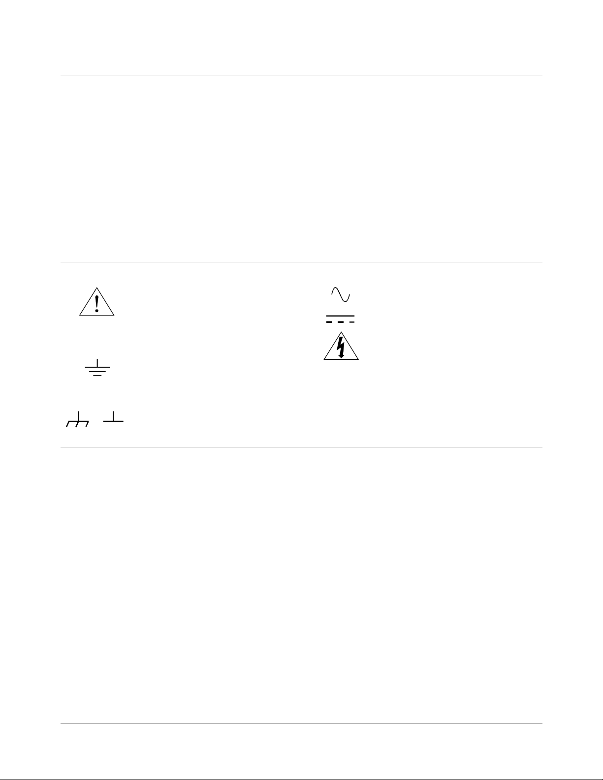
Safety Symbols
Instructio n m a nu a l s ym b ol affixed to pro duct. Indicates that the user must refer to the
manual for specific WARNING or CAUTION information to avoid personal injury
or damage to th e product.
Indicates the field wiring terminal that must
be connected to earth ground before operating the equipment—protects against electrical shock in case of fault.
or
Frame or chassis ground terminal—typically connects to the equipment’s metal
frame.
WARNING
CAUTION
Alternating current (AC).
Direct current (DC).
Indicates hazardous voltages.
Calls attention to a procedure, practice, or
condition that c ould cau se bodi l y in ju ry or
death.
Calls attention to a procedure, practice, or condition that could possibly cause damage to
equipment or pe r m a n e nt loss of data.
WARNINGS
The following general safety precautions must be observed during all phases of operation, service, and repair of this product.
Failure to comply with these precautions or with specific warnings elsewhere in this manual violates safety standards of design,
manufacture, and intended use of the product. Hewlett-Packard Company assumes no liabil ity for the customer’s failure to
comply with these requirements.
Ground the equipment: For Safety Class 1 equipment (equipment having a protective earth terminal), an uninterruptible safety earth
ground must be provid e d from th e mai ns po we r sourc e to the pro du c t in pu t w iring terminals or s upplied power cable.
DO NOT operate the product in an explosive atmosphere or in the presence of flammable gases or fumes.
For continued protection against fire, replace the line fuse(s) only with fuse(s) of the same voltage and current rating and type.
DO NOT use repaired fuses or short-circuited fuse holders.
Keep away from live circuits: Operating personnel must not remove equipment covers or shields. Procedures involving the removal
of covers or shields are for use by service-trained personnel only. Under certain conditions, dangerous voltages may exist even with the
equipment switched off. To avoid dangerous electrical shock, DO NOT perform procedures involving cover or shield removal unless
you are qualified to do so.
DO NOT operate damaged equipment: Whenever it is possible that the safety protection features built into this product have been impaired, either through physical damage, excessive moisture, or any other reason, REMOVE POWER and do not use the product until
safe operation can be verified by service-trained personnel. If necessary, return the product to a Hewlett-Packard Sales and Service Office for service and repair to ensure that safety features are maintained.
DO NOT service or adjust alone: Do not attempt internal service or adjustment unless another person, capable of rendering first aid
and resuscitation, is present.
DO NOT substitute parts or modify equipment: Because of the danger of introducing additional hazards, do not install substitute
parts or perform any unauthorized modification to the product. Return the product to a Hewlett-Packard Sales and Service Office for
service and repair to ensure that safety features are maintained.
8 HP E1326B/E1411B 5 1/2-Digit Multimeter User’s Manual

DECLARATION OF CONFORMITY
SA
Manufacturer’s Name: Agilent Technologies, Incorporated
Manufacturer’s Address: Measurement Product Generation Unit
Declares, that the product
Product Name: B-Size VXI 5 ½ Digital Multimeter
Model Number: E1326B
Conforms with the following European Directives:
The product herewith complies with the requirements of the Low Voltage Directive 73/23/EEC and the EMC Directive 89/336/EEC
and carries the CE Marking accordingly
Conforms with the following product standards:
EMC Standard
Safety
Supplemental Information:
[1]
September 5, 2000
Date
Authorized EU-representative: Agilent Technologies Deutschland GmbH, Herrenberger Stra βe 130, D 71034 Böblingen, Germany
Product Options: This declaration covers all options of the above product(s).
IEC 61326-1:1997+A1:1998 / EN 61326-1:1997+A1:1998
CISPR 11:1997 +A1:1997 / EN 55011:1998
IEC 61000-4 -2:1995+A1:1998 / EN 61000-4-2:1995
IEC 61000-4 -3:1995 / EN 61000-4-3:1995
IEC 61000-4 -4:1995 / EN 61000-4-4:1995
IEC 61000-4 -5:1995 / EN 61000-4-5:1995
IEC 61000-4 -6:1996 / EN 61000-4-6:1996
IEC 61000-4 -11:1994 / EN 61000-4-11:1994
Canada: ICES-001:1998
Australia/New Zealand: AS/NZS 2064.1
IEC 61010-1:1990+A1:1992+A2:1995 / EN 61010-1:1993+A2:1995
Canada: CSA C22.2 No. 1010.1:1992
UL 3111-1:1994
The product was tested in a typical configuration with Agilent Technologies test systems.
For further information, please contact your local Agilent Technologies sales office, agent or distributor.
According to ISO/IEC Guide 22 and CEN/CENELEC EN 45014
815 14th ST. S.W.
Loveland, CO 80537 USA
Limit
Group 1 Class A
4kV CD, 8kV AD
3 V/m, 80-1000 MHz
0.5kV signal lines, 1kV power lines
0.5 kV line-line, 1 kV line -ground
3V, 0.15-80 MHz
I cycle, 100%
Name
Quality Manager
Title
[1]
Revision: A.03 Issue Date: 09/05/00

DECLARATION OF CONFORMITY
SA
Manufacturer’s Name: Agilent Technologies, Incorporated
Manufacturer’s Address: Measurement Product Generation Unit
Declares, that the product
Product Name: 5 ½ Digit Multimeter
Model Number: E1411B
Conforms with the following European Directives:
The product herewith complies with the requirements of the Low Voltage Directive 73/23/EEC and the EMC Directive 89/336/EEC
and carries the CE Marking accordingly
Conforms with the following product standards:
EMC Standard
Safety
Supplemental Information:
[1]
September 5, 2000
Date
Authorized EU-representative: Agilent Technologies Deutschland GmbH, Herrenberger Stra βe 130, D 71034 Böblingen, Germany
Product Options: This declaration covers all options of the above product(s).
IEC 61326-1:1997+A1:1998 / EN 61326-1:1997+A1:1998
CISPR 11:1997 +A1:1997 / EN 55011:1998
IEC 61000-4 -2:1995+A1:1998 / EN 61000-4-2:1995
IEC 61000-4 -3:1995 / EN 61000-4-3:1995
IEC 61000-4 -4:1995 / EN 61000-4-4:1995
IEC 61000-4 -5:1995 / EN 61000-4-5:1995
IEC 61000-4 -6:1996 / EN 61000-4-6:1996
IEC 61000-4 -11:1994 / EN 61000-4-11:1994
Canada: ICES-001:1998
Australia/New Zealand: AS/NZS 2064.1
IEC 61010-1:1990+A1:1992+A2:1995 / EN 61010-1:1993+A2:1995
Canada: CSA C22.2 No. 1010.1:1992
UL 3111-1:1994
The product was tested in a typical configuration with Agilent Technologies test systems.
For further information, please contact your local Agilent Technologies sales office, agent or distributor.
According to ISO/IEC Guide 22 and CEN/CENELEC EN 45014
815 14th ST. S.W.
Loveland, CO 80537 USA
Limit
Group 1 Class A
4kV CD, 8kV AD
3 V/m, 80-1000 MHz
0.5kV signal lines, 1kV power lines
0.5 kV line-line, 1 kV line -ground
3V, 0.15-80 MHz
I cycle, 100%
Name
Quality Manager
Title
[1]
Revision: A.03 Issue Date: 09/05/00

Chapter 1
Getting Started with the HP E1326B/E1411B
Multimeter
About This Chapter
This chapter introduces you the B-size HP E1326B and C-size HP E1411B
1
5
⁄2 - Digit Multimeters. The main se ct io ns of the chapter are:
• Multimeter Overview. . . . . . . . . . . . . . . . . . . . . . . . . . . . . . . Page 13
• Introduction to Operation. . . . . . . . . . . . . . . . . . . . . . . . . . . . Page 16
Note This manual is to be used with the HP E1326B or HP E1411B installed in
the HP 75000 Series B or Series C mainframe, and when the multimeter is
programmed using Standard Commands for Programmable Instruments
(SCPI) language or when it is programmed at the register level.
Multimeter Overview
The HP E1326B/E1411B multimeter is a register-based VXI instrument.
There are two different methods of programming the multimeter based on
the system configuration that it is used in.
If the HP E1326B is used in an HP E1300/E1301/E1302 B-size VXI
mainframe, or if the HP E1326B/E1411B is used in a C-size VXI
mainframe with an HP E1405/E1406 Command Module or with a computer
which has HP Compiled SCPI software, then it may be programmed using
SCPI language. This is the method described in Chapters 1 through 5.
If the HP E1326B is in a VME mainframe or the E1326B/E1411B is in a
C-size VXI mainframe and no HP Command Mo du le or co mpu te r with
Compiled SCPI is present, then the multimeter must be programmed at the
register level. Appendix C covers register level programming.
The HP SCPI driver provides an error queue, input and output buffers,
status registers, and is allocated a portion of mainframe memory for reading
storage. This "instrument" may consist of the multimeter, or it can also
include multiplexers such as the HP E1345A/46A/47A/51A/53A and the
HP E1460A/76A. The instrument is operated from the mainframe front
panel or from a computer using the SCPI language.
Instruments are bas ed on th e logical addresse s of the plu g- in mo du le s. The
HP VXIbus Systems Installation and Getting Started Guide explains how to
Chapter 1 Getting Started with the HP E1326B/E1411B Multimeter 13

set the addresses in order to create an instrument. The guide should be your
starting point toward using the multimeter. The functions and features of
the multimeter are presented in the following functional, electrical, and
physical descriptions.
Functional
Description
Measurement
Functions
Configuring the
Multimeter
The 51⁄2 - digit multimeter ca n be use d stand-alone, or com bi ne d w it h
multiplexers (for example, HP E1345A/46A/47A/51A/52A/55A/56A/
57A/58A or HP E1460A/76A) to form a scanning multimeter.
In stand-alone operation, input signals are connected to the multimeter’s
external (faceplate) terminals. In scanning operation, input signals are
connected to the multiplexer channels. The multimeter is linked to relay
multiplexer(s) via an analog bus cable. The multimeter is linked to FET
multiplexers via an analog cable and a digital bus cable.
The multimeter’s measurement functions are shown below. These functions
are typical of those required for many data acquisition and computer aided
test applications.
– DC Voltage
– RMS AC voltage
– 2-Wire Resistance (scanning multimeter only)
– 4-Wire Resistance
– Temperature (thermistors, RTDs, thermocouples)
With MEASure or CONFigure, the multimeter is configured for
measurements using a single command. When necessary, low-level
commands are available to set configurations for unique applications. Such
commands, for example, allow you to enable autozero or offset
compensation, or change various analog-to-digital (A/D) converter
parameters.
Triggering the
Multimeter
The multimeter’s trigger system allows it to be internally or externally
triggered. The system enables you to scan a multiplexer channel list
multiple times, or in the stand-alone configuration, take multiple readings
per trigger. An on-board timer allows you to pace measurements.
Reading Storage Readings are returned directly to the multimeter’s output buffer or are
stored in mainframe memory. The total number of readings which can be
stored (all multimeters combined) depends on the amount of memory
available. Each reading stored will consume four bytes of m emory.
Saving Configurations To minimize repeated programming, up to 10 stand-alone multimeter
configurations can be saved and recalled. The configurations remain in
memory until a new configuration is saved or until power is cycled.
Electrical
Description
The electrical performance of the multimeter is summarized in Table 1-1.
Refer to Appendix A for a complete table of specifications.
14 Getting Started with the H P E1 326B/E1411B Mul t i m et er Chapter 1

Table 1-1. HP E1326B/E1411B Operating Characteristics
DC Voltage
Ranges
Resolution
Accuracy (90 days)
Max Rdgs/se c
AC RMS Voltage
Ranges
Resolution
Accuracy (90 days)
Frequency Range
2-Wire and 4-Wire Resistance
Ranges
Resolution
Accuracy (90 days)
Physical
Description
0.125V, 1.0V, 8.0V, 64. 0V, 300V full scale.
120nV on 0.125V range with 20/16.7 msec aperture time.
0.01%
13,150
0.0875V, 0.7V, 5.6 V, 44 .8 V, 30 0V fu ll scale.
29.8nV on 0.0875V range with 320/267 msec aperture time.
0.625%
20 Hz to 10 kHz
256Ω, 2048Ω, 16384Ω, 131072Ω, 1048576Ω full scale.
250mΩ on 256Ω range with 20/16.7 msec aperture time.
0.025%
The 51⁄2 - digit multimeter occupies one B-Size or one C-Size mainframe
slot. However, the faceplate of the B-size multimeter covers up an
additional slot in the B-Size mainframe. This prevents another B-size card
from being installed in the slot directly above the multimeter. An internal
installation kit, discussed in Chapter 2, enables you to install the multimeter
internal to the H P 75 0 00 Seri es B mai nf ra me. This saves two exter na lly
accessed slots.
Input Terminals There are four input terminals on the faceplate of the multimeter
(see Figure 2-7 on page 29). The terminals, which are isolated from chassis
ground, are used to connect input signals when the multimeter is used
stand-alone.
A high-to-low TTL pulse applied to the External Trigger port externally
triggers the multimeter. The Analog Bus and Digital Bus ports allow relay
and FET multiplexers to be connected to the multimeter.
Chapter 1 Getting Started with the HP E1326B/E1411B Multimeter 15

Introduction to Operation
This section contai ns inf or mat io n on che ck in g co m mun ic at ion be twe en the
multimeter, mainframe, and computer. It includes information on returning
the multimeter to a known operating state should programming errors occur
or if you simply want to start over. It also shows how to send a command to
configure the multimeter and make a measurement.
Note The HP E1411B has a "Failed" annunciator and an "Access" annunciator on
the faceplate. The "Failed" annunciator turns on if the multimeter does not
properly respond during the mainframe’s power-on sequence. If this
occurs, return the multimeter to Hewlett-Packard for service. The "Access"
annunciator turns on each time the multimeter receives a command.
Multimeter Self-Test Once the mainframe completes its power-on sequence, the multimeter is
ready for use. Sending the self-test command is an easy way to verify that
you are properly add re ss in g th e m ul ti met er . Also, the self-test is use fu l in
locating intermittent problems that might occur during operation. The
command us ed to ex ec ut e th e self-test is:
*TST?
You can also run the self-test by selecting “TEST” from the multimeter’s
front panel menu on the HP E1301A mainframe. Upon execution, the
self-test resets the multimeter, performs the test, and returns one of the
codes listed in Tab le 1-2 .
The following program executes the self-test. The program assumes the
mainframe (command module for C-size systems) is at primary HP-IB
address of 09 and the multimeter is at secondary address 03. The program
also assumes an HP 9000 Series 200/300 computer is used.
10 !Send the self-test command to the multimeter.
20 OUTPUT 70903;"*TST?"
30 !
40 ENTER 70903;A
50 PRINT A
60 !
70 OUTPUT 70903;"*RST"
80 END
Enter and display the self-test code.
Reset the multimeter.
After the test passes, always reset the multimeter to return it to a known state.
16 Getting Started with the H P E1 326B/E1411B Mul t i m et er Chapter 1

Table 1-2. HP E1326/E1411 Self-Test Codes
Self-Test
Code Description
0 Test passed.
1 Multimeter does not resp ond to the self-test.
2 Invalid communication between the multimeter’s two on-board processors.
3 Data line test between the multimeter and the mainframe command module failed.
4 Invalid communication between the multimeter and mainframe command module.
If self-test code 1, 2, 3, or 4 occurs, return the multimeter to Hewlett-Packard for repair.
Note If the multimeter did not respond to the self-test, the address you specified
may be incorrect. Refer to Chapter 2 in this manual and the HP VXIbus
Systems Installation and Getting Started Guide.
Resetting the
Multimeter
During operation, programming errors and other conditions may occur
making it necessary to reset the multimeter. This section shows you how to
reset and clear th e m ul tim et er, an d re ad its err or que u e .
The multimeter is reset with the command:
*RST
which can be sent from an HP 9000 Series 200/300 computer as:
OUTPUT 70903;"*RST"
The multimeter ca n al so be re se t by pre ss in g th e gr ee n “ Re se t Ins tr ” ke y on
the HP E1301A mainframe front panel. Note that the multimeter must first
be selected from the mainframe menu.
When resetting the multimeter:
• A front panel reset (“Reset Instr” key on the HP E1301A mainframe)
returns the multimeter to the idle state from the busy state and sets the
multimeter’s power-on configuration (Table 1-3). A front panel reset is
equivalent to clearing the multimeter followed by a reset.
• A reset from the com p u te r (*RST) returns the multimeter to the idle
state from the busy state if the multimet er is bu sy due to a co m m an d
entered from the front panel. If the multimeter is busy due to a
command sent from the computer, you must clear the multimeter
before sending the reset. The reset sets the multimeter’s power-on
configuration.
Chapter 1 Getting Started with the HP E1326B/E1411B Multimeter 17

Table 1-3. HP E1326/E1411 Power-on Settings
Parameter Setting
FUNCtion VOLT:DC
VOLTage:RANGe 8V
RESistance:RANGe
16384Ω
VOLTage:RANGe:AUTO ON
RESistance:RANGe:AUTO ON
VOLTage:RESolution 7.629
RESistance:RESolution
µ
15.6 mΩ
V
VOLTage:APERture 16.7 ms or 20 ms (based on line frequency )
RESistance:APERture 16.7 ms or 20 ms (based on line frequency )
CALibratio n:LFRequency Unchan ged (factory set ting = 60 Hz)
VOLTage:NPLC 1
RESistance:NPLC 1
RESistance:OCOMpensated OFF
CALibration:ZERO:AUTO ON
TRIGger:COUNt 1
TRIGger:DELay:AUTO ON
TRIGger:SOURce IMM
SAMPle:COUNt 1
SAMPle:SOURce IMM
18 Getting Started with the H P E1 326B/E1411B Mul t i m et er Chapter 1

Clearing the Multimeter When the multimeter is selected from the HP E1301A mainframe menu, the
multimeter is cleared by pressing the “Clear Instr” key on the front panel.
The multimeter is also cleared by sending the following command from an
HP 9000 Series 200 or Series 300 controller:
CLEAR 70903
Clearing the multimeter:
– allows you to regain control without cycling power and without
setting the pow er -o n co nf ig ur at io n.
– with the HP E1301A “Clear Instr” key terminates any
command entered from the front panel. A command sent from
the computer w ill st ill co nt in ue to ex ec ut e.
– from the computer (CLEAR 70903) terminates any command
sent from the computer. A command entered from the
HP E1301A front panel will still continue to execute.
– erases any pending commands. For example, if commands are
sent from the computer to the multimeter while the multimeter is
waiting for an external trigger, the commands are buffered until
they can execute after the trigger is received. Clearing the
multimeter (from the computer) erases those commands.
Similarly, clearing the multimeter from the HP E1301A front
panel erases any pending front panel commands.
– if cleared from the HP E1301A front panel, the display buffer is
cleared. If cleared o ve r HP-IB, the data in the outp ut buf fe r is
erased.
The Error Queue When an error occurs during operation, an error code and corresponding
message are stored in the multimeter’s error queue. If the Series B
mainframe has a display (HP E1301A) and the multimeter is being
monitored, the "err" annunciator will turn on.
Since many mainframes may not have a front panel display, the other way
to determine if an er ro r ha s oc cu rr ed is to rea d th e er ro r qu eu e. This is done
with the command:
SYSTem:ERR?
The following program shows how the command is used to read and clear
the error queu e.
10 !Declare a string variable in the computer to store the error message.
20 DIM Message$[256]
30 !
40 !Print the error codes and messages.
50 REPEAT
60 OUTPUT 70903;"SYST:ERR?"
70 ENTER 70903;Code,Message$
80 PRINT Code,Message$
90 UNTIL Code=0
100 END
Read the error queue until no errors remain.
Chapter 1 Getting Started with the HP E1326B/E1411B Multimeter 19

The error queue can store up to 30 error messages which are retrieved in a
first in, first ou t (FI F O) m anner. When th er e ar e no err or me ss ag es in th e
queue, a code of 0 and the message "No Error" are returned. Errors
generated during front panel operation are displayed but are not stored in
the error queu e.
Note Appendix B contains a list of error messages associated with the multimeter
and their causes.
Making a
Measurement
Example: Making a
Measurement
(Stand-Alone
Multimeter)
Example: Making a
Measurement
(Scanning Multimeter)
The HP E1326B/E1411B multimeter can be configured and make
measurements using the
show how it is used with the stand-alone and scanning multimeters.
This example uses the MEASure command to make a DC voltage
measurement on the terminals connected to the multimeter’s faceplate.
The reading is then entered into the computer and displayed.
10 OUTPUT 70903;"MEAS:VOLT:DC?"
20 ENTER 70903;Rdg
30 PRINT Rdg
40 END
This example uses the MEASure command to scan a list of multiplexer
channels and make a DC voltage measurement on each channel. The
readings are then entered into the computer and displayed.
10 DIM Rdgs(1:5)
20 OUTPUT 70903;"MEAS:VOLT:DC? (@100:104)"
30 ENTER 70903;Rdgs(*)
40 PRINT Rdgs(*)
50 END
MEASure command. The following examples
20 Getting Started with the H P E1 326B/E1411B Mul t i m et er Chapter 1

Configuring the HP E1326B/E1411B
About This Chapter
This chapter contains information on connecting input signals to the
multimeter using multiplexers and using the terminals on the multimeter’s
faceplate. The main sections of the chapter are:
WARNING SHOCK HAZARD. Only service-trained personnel who are
aware of the hazards involved should install or configure the
multimeter. Remove all sources of power to the multimeter and
mainframe before removing the multimeter.
Chapter 2
Multimeter
• Installation Overview. . . . . . . . . . . . . . . . . . . . . . . . . . . . . . . Page 21
• Input Characteristics . . . . . . . . . . . . . . . . . . . . . . . . . . . . . . . Page 28
• Connecting Input Signals. . . . . . . . . . . . . . . . . . . . . . . . . . . . Page 32
• Carrier Cable Assemblies . . . . . . . . . . . . . . . . . . . . . . . . . . . Page 37
• Additional Configurations . . . . . . . . . . . . . . . . . . . . . . . . . . . Page 39
The maximum allowable input on the multimeter terminals is
300 V dc (450 V ac peak). Since the terminals are isolated from
the multimeter chassis, the potential between the terminals and
the chassis is equal to the value of the input signal.
Installation Overview
As mentioned in the HP VXIbus Systems Installation and Getting Started
Guide, each plug-in module has a row of switches which set the module’s
logical addres s. Based on this add re ss , th e sy st em in st ru m en t w it hi n th e
HP 75000 Series B mainframe and HP E1406A command module combines
the modules into virtual instruments. The instruments are programmed by a
computer using SCPI language or from a computer by writing commands
directly to the multimeter registers (see Appendix C).
This section shows the location of the multimeter’s logical address switch
and shows how it is set. It also mentions considerations when installing the
multimeter in the mainframe.
Chapter 2 Configuring the H P E1 32 6B/E1411B Multim eter 21

Setting the Logical
Address Switch
Figure 2-1 shows the location and settings of the multimeter’s logical
address switch.
The switch has a factory setting of 24 which is equivalent to a secondary
HP-IB address of 03. If you have more than one multimeter, you must change
the logical address to some other multiple of 8 (for example, 32, 40, 48...), as
there can only be one instrument per secondary address.
Figure 2-1. HP E1326/1411 Logical Address Switch Settings
22 Configuring the HP E1326B/E1411B Multimeter Chapter 2

Forming a Scanning
Multimeter
If multiplexers are used to form a scanning multimeter, they must be
assigned successive logical addresses beginning with the address
immediately following that of the multimeter. An example is shown in
Figure 2-2.
The scanning multimeter can consist of relay multiplexers, FET
multiplexers, or a combination of both. See “Connecting Multiplexers” on
page 30 for information on physically connecting the multiplexers to the
multimeter.
Figure 2-2. Setting Successive Logical Addresses to Form
an Instrument
Chapter 2 Configuring the H P E1 32 6B/E1411B Multim eter 23

VXIbus Interrupt
Lines
Note IRQ OFF is set when the multimeter is installed in systems without a Series B
The multimeter sends interrupts to, and receives acknowledgements from
the slot 0 module via the VXIbus backplane interrupt lines. Since the
multimeter is a nonprogrammable interrupter, the interrupt line is selected
with the multimeter’s IRQ jumper.
There are seven backplane interrupt lines. At the factory, the IRQ jumper is
set to line 1. The system instrument in the Series B mainframe is assigned
to each line, and the system instrument in the HP E1406A command module
is assigned to line 1 by default. Therefore, in Series B systems it is not
necessary to change the IRQ jumper setting. If the command module in
Series C systems is assigned another line and the multimeter is to use that
line, the IRQ jumper must be set accordingly. Figure 2-3 shows the location
of the jumpers used to select an interrupt line. For most applications where
the multimeter is installed in an HP 75000 Series B or Series C mainframe,
the jumpers do not have to be moved.
mainframe or HP E1406A command module.
Interrupt Priority In the HP 75000 Series B and Series C mainframes, the VXIbus interrupt
lines have the same priority; therefore, interrupt priority is established by
installing modules in slots numerically closest to the slot 0 module. Thus,
slot 1 (internal on the Series B mainframe) has a higher priority than slot 2
(also internal), slot 2 has a higher priority than slot 3, and so on.
HP E1411BHP E1326B
Interrupt
Jumper
Location
Interrupt
Jumper
Location
Figure 2-3. Interrupt Jumper Locations
24 Configuring the HP E1326B/E1411B Multimeter Chapter 2

HP E1326B Internal
Installation
When the HP E1326B is installed in an HP E1300A/E1301A/E1302A
mainframe, it occupies one slot. However, the faceplate to which the input
terminals are connected covers up an additional slot. This prevents another
module from being installed in the slot directly above the multimeter.
To make the two slots available to other modules, the HP E1326B can be
installed internal to the mainframe (in slot 2) using an internal installation
kit (HP P/N E1326-80004).
Multimeter installation into the external slots is covered in the Installation
and Getting Started Guide. Instructions for installing the multimeter
internally are included in the installation kit.
Connecting the
HP E1326B Adapter
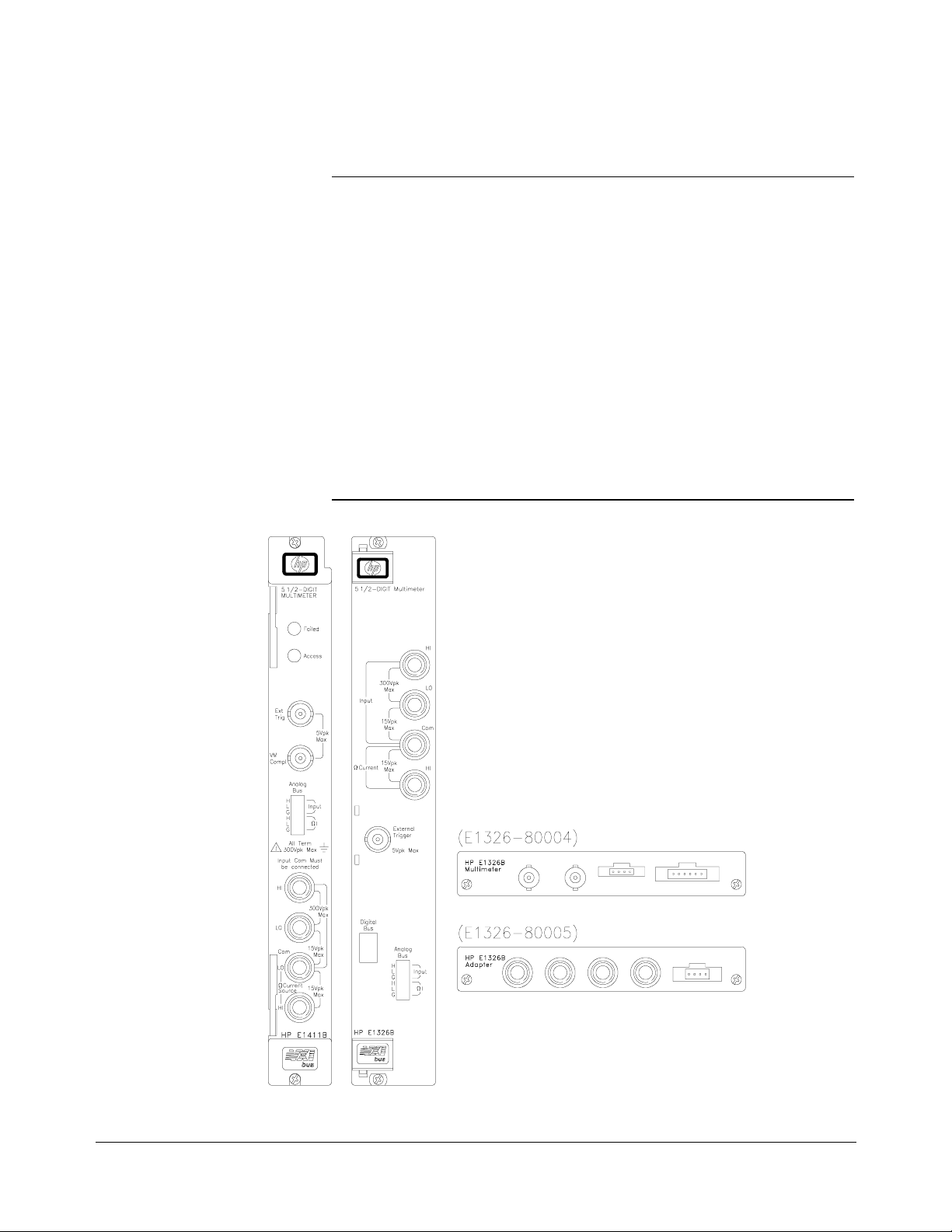
If the HP E1326B multimeter is installed internal to the HP E1300A/E1301A
mainfra me, the HP E1326-80005 adapter can be used to provide HI, LO,
COM, and HI banana plug terminals for the multimeter. When the adapter
is connected as shown in Figure 2-4, the terminals, rather than the
multiplexer, are the input to the multimeter.
Figure 2-4. Connecting the HP E1326B Adapter
Chapter 2 Configuring the H P E1 32 6B/E1411B Multim eter 25

Installing the
HP E1411B in a
Mainframe
Set the extraction levers out.
The HP E1411B multimeter can be installed in any slot (except slot 0) in a
C-size VXIbus mainframe. Refer to Figure 2-5 to install the E1411B in a
mainframe.
Slide the multimeter into any slot
(except slot 0) until the backplane
connectors touch.
Tighten the top and bottom screws
to secure the multimeter to the
mainframe.
Seat the multimeter into
the mainframe by pushing
in the extraction levers.
To remove the multimeter from the mainframe,
reverse the procedure.
Figure 2-5. Installing the HP E1411B Multimeter in a VXIbus Mainframe
26 Configuring the HP E1326B/E1411B Multimeter Chapter 2

The Reference
Frequency
In many data acquisition applications, DC voltage and resistance
measurements are often made in the presence of normal mode noise. This
type of noise emanates from the surrounding environment, primarily from
50 Hz and 60 Hz power lines. The HP E1326B/E1411B multimeter is able
to reject normal mode noise by using an integrating analog-to-digital (A/D)
converter. The integration process averages out the power line related noise
over an integer number of power line cycles (PLCs) during the A/D
conversion. The multimeter’s ability to reject noise at the power line
frequency is expressed in terms of normal mode rejection (NMR).
Setting the Reference
Frequency
Querying the
Reference Frequency
In certain applications, the multimeter’s power line frequency may be
different from the line frequency of the device being measured. Assume,
for example, the multimeter has a power line frequency of 60 Hz and the
device being measured has a line frequency of 400 Hz. Normal mode
rejection can be achieved by setting the reference frequency to 50 Hz.
This is done with the command:
CALibration:LFRequency frequency | MIN | MAX
frequency is power line frequency. Settings are 50 or 60.
MIN sets the minimum power line frequency (50 Hz).
MAX sets the maximum power line frequency (60 Hz).
The reference frequency is set to 60 Hz at the factory. The setting is stored
in non-volatile memory and is changed only when
is executed.
The reference frequency is queried with the following commands.
See Chapter 5 for additional information about these commands.
CALibration:LFRequency?
CALibration:LFrequency? MIN | MAX
CALibration:LFRequency
Chapter 2 Configuring the H P E1 32 6B/E1411B Multim eter 27

Input Characteristics
The multimeter is a floating, balanced differential multimeter. Floating means
the multimeter’s input terminals are isolated from its chassis. A balanced
differential multimeter is one where the input impedance between HI and COM
is the same as the impedance between LO and COM (see Figure 2-6). The
only difference between the HI and LO terminals is the polarity.
Figure 2-6. A Floating, Balanced Differential Multimeter
28 Configuring the HP E1326B/E1411B Multimeter Chapter 2
Input Terminals The multimeter input terminals are shown in Figure 2-7. The maximum
input on the HI and LO terminals is 300 V dc (450 V ac peak). The
maximum amount of common mode voltage developed between LO and
COM and HI (current) and COM cannot exceed 15 V peak.
CAUTION A maximum voltage of 300 V dc (450 V ac peak) is allowed on
the multimeter’s rear terminals. Multiplexers connected to the
multimeter reduce the voltage that can be applied between the
multiplexer’s High (H), Low (L), and Guard terminals, to the
level specified for the multiplexer. For example,
HP E1343A/44A 250 V dc or 354 V ac peak
HP E1345A/47A 120 V dc or 170 V ac peak
HP E1351A 14 V dc or ac peak
Mixing of multiplexer types reduces all voltage ratings to that of
the lowest rated multiplexer. For example, if an HP E1343A and
E1351A are connected to the same multimeter, then the system
rating is that of the E1351A, which is 14 V.
Figure 2-7. HP E1326B/E1411B Input Terminals
Chapter 2 Configuring the H P E1 32 6B/E1411B Multim eter 29

Connecting
Multiplexers
In a scanning multimeter configuration, the multimeter is connected to the
multiplexers with an analog bus cable, or with the analog bus cable and a
digital bus cable. The cable(s) used is determined as follows:
1. If the scanning multimeter uses relay multiplexer s onl y, the analog
bus cable is used.
2. If the scanning multimeter uses FET multiplexers only, the analog
bus cable and the digital bus cable are used.
3. If the scanning multimeter uses a combination of relay and FET
multiplexers, only the analog bus cable is used.
Figure 2-8 shows how the analog and digital bus cables are connected.
Figure 2-8. Connecting the Analog and Digital Bus Cables
30 Configuring the HP E1326B/E1411B Multimeter Chapter 2
Analog Bus
Connections at the
Multimeter
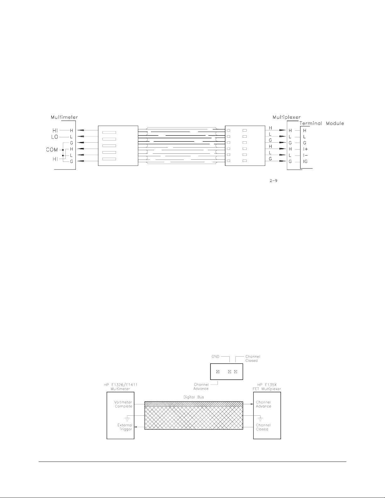
The analog bus coming from the multiplexer consists of six lines. On the
multiplexer terminal block these lines are labeled:
H L G I+ I- IG
Where the ribbon cable connects the multiplexer to the multimeter the lines
are labeled:
H L G H L G
The lines are then connected to the multimeter’s HI LO COM HI lines as
shown in Figure 2-9.
Figure 2-9. Analog Bus Connections
Digital Bus Over view The digital bus cable coordinates the operation (handshaking) between the
multimeter and FET multiplexers without involvement from the system
instrument. This enables the multimeter to scan the FET channels at a rate
of approximately 13,150 channels/sec.
The digital bus consists of a Voltmeter Complete line, an (external) Trigger
line, and ground. The handshake sequence is described in the following
steps and in Figure 2-10.
1. When a FET channel is closed, a "channel closed " signa l is sent over
the Trigger line. This triggers the multimeter which, in turn, makes a
measurement.
2. When the measurement is finished, a "voltmeter complete" signal is
sent from the multimeter to the multiplexer on the Voltmeter
Complete line. This signal advances the scan to the next channel in
the list. When the channel is closed, the channel closed signal
triggers the multimeter and the process repeats.
Figure 2-10. Digital Bus Overview
Chapter 2 Configuring the H P E1 32 6B/E1411B Multim eter 31

Connecting Input Signals
This section contains guidelines on connecting input signals to the
multimeter and shows the connections required to make the following
measurements:
• DC and AC RMS Voltage
• 2-Wire Resistance (including thermistors and RTDs)
• 4-Wire Resistance (including thermistors and RTDs)
• Thermocouples
Note Refer to the HP E1355A - E1358A Strain Gage Multiplexers User’s Manual
for information on connecting strain gages.
Wiring
Considerations
Connecting the
COM Lead
WARNING The HI, LO, COM, HI terminals on the multimeter faceplate are
To ensure accurate measurements, input signals should be connected to the
multimeter (via its rear terminals or a multiplexer) using a shielded
twisted-pair cable. Twisted-pair cables reduce magnetic (inductive) noise in
the measurement circuit. The shield reduces electrical (capacitive) noise.
To prevent the HI and LO terminals from floating from the COM terminal
and causing erratic overload readings, the COM terminal must be connected
to the signal source. If a shielded cable is used, connect one end of the
cable shield to the LO lead at the signal source, and connect the other end of
the cable shie ld to th e C OM (or gu a rd ) te rmi na l. If a s hi eld e d ca bl e is not
used, connect a COM (guard) lead with the LO lead AT THE SIGNAL
SOURCE. These connections (Figure 2-11), apply to measurement using
the rear terminals or multiplexers.
internally connected to the analog bus port. Thus, signals on
the analog bus (from a multiplexer) appear on the faceplate
terminals and vice versa.
Figure 2-11. Connecting the COM Lead
32 Configuring the HP E1326B/E1411B Multimeter Chapter 2

Measurement
Connections
E1345A/47A/51A/53A
E1460A
E1346A
E1352A
Figure 2-12. Connections for DC and AC Voltage Measurements
Chapter 2 Configuring the H P E1 32 6B/E1411B Multim eter 33

E1345A/47A/51A/53A
E1460A E1346A
Figure 2-13. Connections for 2-Wire Resistance Measurements
(Including Thermistors and RTDs)
E1352A
Note 2-wire resistance measurements require the multiplexer modules shown
above. Resistance measurements using the mul timeter terminals or directly
through the analog bus must be configured as 4-wire measurements.
34 Configuring the HP E1326B/E1411B Multimeter Chapter 2

E1460A
E1345A/47A/51A/53A
NOTE: Channel Pairs are banks 0/4, 1/5, 2/6, and 3/7.
See Chapter 2 of the
HP E1460A User ’s Ma nual.
Figure 2-14. Connections for 4-Wire Resistance Measurements
(Including Thermistors and RTDs)
Chapter 2 Configuring the H P E1 32 6B/E1411B Multim eter 35

E1344A/47A/53A
E1476A
Figure 2-15. Connections for Thermocouples
36 Configuring the HP E1326B/E1411B Multimeter Chapter 2

Carrier Cable Assemblies
The following table and figures show the cables used to connect relay and
FET multiplexers to the HP E1411B multimeter. These cables are required
when the (B-S iz e) mu lt ip le xe rs are ins ta ll ed in the Series C main fr ame
using the HP E1403B A/B-to-C-size module adapter.
Table 2-1. Cable Assemblies
Configuration 1: HP E13 45 A/4 6A/47A/55A or 56A (relay mult ip le xe r) in HP E140 3B mo du le ada pt er.
Configuration 2: HP E13 51 A/5 2A/53A/57A or 58A (FET multip le xe r) in HP E140 3B mo du le ada pt er.
Cable assemblies for HP E1411B multimeter-to-multiplexer connections
Configuration 1 Configuration 2
Connecting the HP E1411B to: E1326-61611 (analog bus) E1326-61611 (analog bus)
E1411-61601 (digital bus)
Cable assemblies for multiplexer-to-multiplexer connections
Configuration 1 Configuration 2
Connecting Configuration 1 to: E1400-61605 (analog bus) E1400-61605 (analog bus)
Connecting Configuration 2 to: E1400-61605 (analog bus) E1400-61605 (analog bus)
E1400-61601 (digital bus)
Examples:
1. To connect the HP E1411B multimeter to a FET multiple xer in the HP E1403B module adapter
(configuration 2), the analo g an d di gi ta l bu s ca bl es in ki t E14 00 -80 001 are required.
2. To connect a FET multiplexer in the HP E1403B module adapter (configurat ion 2) to a relay
multiplexer in the E1403B adapte r (con fi gu ration 1), the E1400-61605 ana lo g bu s ca bl e is requ ire d.
Notes:
1. The HP E1326-61611 analog bus cable and HP E1411-61601 digital bus cable are available
under kit part number E1411-80001. This kit is not included with the multimeter or multiplexers.
It must be ordered separately.
2. The HP E1400-61605 analog bus cable ships with the HP E1345A/46A/47A/55A and 56A relay
multiplexers. The HP E1400-61605 analog bus cable and HP E1400-61601 digital bus cable
ship with the HP E1351A/52A/53A/57A/58A FET multiplexers.
and
Chapter 2 Configuring the H P E1 32 6B/E1411B Multim eter 37

Figure 2-16. Cables for B-Size Multiplexers in HP E1403B Adapter
38 Configuring the HP E1326B/E1411B Multimeter Chapter 2

Additional Configurations
This section contains information on two additional configurations for the
multimeter:
• selecting VME RAM, and
• disabling front-panel for stand-alone applications.
Selecting VME RAM Up to 12 Mbytes of VME RAM can be added to the B-size mainframe to
be used for multimeter reading storage. The following lists guidelines for
using VME RAM with the multimeter:
• Dynamic RAM must handle its own refresh, and not require any
command module activity.
• VME cards can never be a bus master.
– B-size mainframe does not have bus arbitration.
• VME cards must ex cl ud e th e fi rs t an d la st 2 Mb yt es of A2 4 spa ce .
– B-size mainframe’s system ROM is located in the lower
2 Mbytes.
– B-size mainframe’s system RAM is located in the upper
2 Mbytes.
Disabling
Front-panel for
Stand-alone
Applications
• VME RAM may not be used for IBASIC progr am m emo ry .
The following lists guidelines in selecting a VME card:
A24 A24 address space
D16 16 bits of data at a time
3U A size slot
6U B size slot
When using the HP E1326B Multimeter as a stand-alone instrument, the
HP E1301A front-panel keyboard can be disabled without disabling the
display. To disable the front-panel keyboard, use the following guidelines:
– send a "REMOTE" command to each instrument, and
– send a "LOCAL LOCKOUT" to the HP-IB interface.
This should allow the display to still work, but disable the keyboard and the
softkeys.
Chapter 2 Configuring the H P E1 32 6B /E 14 11 B M ultimeter 39

Notes
40 Configuring the HP E1326B/E1411B Multimeter Chapter 2

Using the HP E1326B/E1411B Multimeter
About This Chapter
This chapter is a collection of example programs which show you how to
make measure ments with various mu lt ime te r co nf ig ur at io ns . The examples
in this ch apter include:
Chapter 3
• Making a Single Measurement . . . . . . . . . . . . . . . . . . . . . . . Page 42
• Making a Burst of Measurements . . . . . . . . . . . . . . . . . . . . . Page 43
• Making an Externally Triggered Burst of
Measurements. . . . . . . . . . . . . . . . . . . . . . . . . . . . . . . . . Page 44
• Making Multiple Burst Measurements . . . . . . . . . . . . . . . . . Page 45
• Scanning a Channel List . . . . . . . . . . . . . . . . . . . . . . . . . . . . Page 46
• Making Multiple Scans . . . . . . . . . . . . . . . . . . . . . . . . . . . . . Page 47
• Making Multiple Paced Scans . . . . . . . . . . . . . . . . . . . . . . . . Page 48
• Making an Externally Triggered Scan. . . . . . . . . . . . . . . . . . Page 49
• Scanning Switchbox Channels (E1326B/1351A) . . . . . . . . . Page 50
• Scanning Switchbox Channels (E1411B/1460A. . . . . . . . . . Page 52
• Multiple High-Speed Scans . . . . . . . . . . . . . . . . . . . . . . . . . . Page 54
• Maximizing Measurement Speed . . . . . . . . . . . . . . . . . . . . . Page 56
• Changing the Data Format. . . . . . . . . . . . . . . . . . . . . . . . . . . Page 58
• Using a PC, C Language, and the HP 82335 HP-IB
Interface Card . . . . . . . . . . . . . . . . . . . . . . . . . . . . . . . . . Page 60
• Maximizing Measurement Accuracy. . . . . . . . . . . . . . . . . . . Page 63
• Storing Readings in Shared Memory. . . . . . . . . . . . . . . . . . . Page 64
• Checking for Errors . . . . . . . . . . . . . . . . . . . . . . . . . . . . . . . . Page 66
• Synchronizing the Multimeter with a Computer. . . . . . . . . . Page 68
• Additional Measurement Functions. . . . . . . . . . . . . . . . . . . . Page 69
Using the Programs The purpose of the chapter is to provide example programs that show you
how to operate the multimeter. With minor modifications, these programs
can also be used for many of your applications.
Programming
Language
Chapter 3 Using the HP E1326B/E1411B Multimeter 41
The example progra ms ar e sh ow n in th e Hew let t- Pac ka rd BASI C langu ag e
and assume the multimeter is controlled from an HP 9000 Series 200/300
computer over the HP-IB. When using HP BASIC, a command is sent to
the multimeter with the
OUTPUT 70903;"MEAS:VOLT:DC? (@100)"
The destination specified (70903) is the interface select code of the
computer (7), plus the HP-IB addresses of the HP 75000 Series B
mainframe or Series C command module (09), and the multimeter (03).
The multimeter command is enclosed between quotation marks. Use
ENTER to enter data from the multimeter is entered into the computer:
ENTER 70903;variable
OUTPUT statement:

Multimeter Connections Chapter 2 contains information on connecting input signals for the
measurements described in this chapter.
The MEASure and
CONFigure Commands
Measurement
Functions other than
DC Voltage
All of the example programs use the MEASure or CONFigure commands.
These commands configure the multimeter, and are equivalent to executing
several other multimeter commands. The
place of
command are re qu ir ed .
Recall from Chapter 1 that the HP E1326B/E1411B can function
stand-alone, or with multiplexers as a scanning multimeter instrument.
When programming, the stand-alone multimeter and scanning multimeter
are distinguished by the absence or presence of the
parameter in the MEASure or CONFigure command. Chapter 4 provides
details on these commands and the multimeter configurations they set.
In each of the programs, the measurement function specified is DC voltage.
The function can be changed by changing the
command. The different functions available are shown following the last
example program.
MEASure when changes to the configuration set by either
Making a Single Measurement
This program makes a single DC voltage measurement on the terminals
connected to the multimeter’s faceplate using the configuration set by the
MEASure command.
CONFigure command is used in
(@channel_list)
MEASure or CONFigure
Comments
10 !Clear and reset the multi met er .
20 CLEAR 70903
30 OUTPUT 70903;"*RST"
40 !
50 OUTPUT 70903;"MEAS:VOLT:DC?"
60 !
70 ENTER 70903;A
80 PRINT A
90 END
Configure th e mu lti met er an d ma ke a DC vo lt ag e m ea su re m en t.
Enter and display the reading on the computer.
• The scanning multimeter (multimeter plus multiplexers) is required
to make 2-wire measurements (resistance, thermistors, RTDs) or
thermocouple measurements.
42 Using the HP E1326B /E1411B Multimeter Chapter 3

Making a Burst of Measurements
This program makes 100 DC voltage measurements on the terminals
connected to the multimeter’s faceplate.
10 !Dimension a computer array to store the read ing s.
20 DIM Rdgs(1:100)
Comments
30 !
40 CLEAR 70903
50 OUTPUT 70903;"*RST"
60 !
70 !readings, store the readings in mainframe memory until all readings are
80 !taken. Fetch the read ings from memory and place them in the output buffer.
90 OUTPUT 70903;"CONF:VOLT:DC"
100 OUTPUT 70903;" SAMP:COUN 100"
110 OUTPUT 70903;"INIT"
120 OUTPUT 70903;"FETCH?"
130 !
140 ENTER 70903;Rdgs(*)
150 PRINT Rdgs(1),Rdgs(50),Rdgs(100)
160 END
Clear and reset the multimeter.
Configure the multimeter for DC voltage measurements. Take a burst of 100
Enter the readings into the computer. Display selected measurements.
• CONFigure sets a burst consisting of one measurement. The
SAMPle:COUNt command is used to set a burst of measurements
greater than one. Up to 16,777,215 measurements can be specified
SAMPle:COUNt.
with
• When INIT follows CONFigure, the readings are stored in mainframe
memory.
output buffer once all measurements are taken. Replacing
FETCH? with READ? returns the readings directly to the output
buffer. Readings should be stored in memory first, rather than
returned directly to the output buffer, when measurement speed is
critical.
FETCH? retrieves the readings and places them in the
INIT and
• Readings are returned directly to the multimeter’s output buffer, or
are stored in mainf ra me m em o ry on in me mor y shared by the
VXIbus system. The total number of readings which can be stored
depends on the amount of memory available. Each reading stored
will consume four bytes of memory.
• A burst of measurements (set by SAMPle:COUNt) can also be m ad e
when scanning a single channel.
Chapter 3 Using the HP E1326B/E1411B Multimeter 43

Making an Externally Triggered Burst of Measurements
This program makes a burst of 10 measurements on the faceplate terminals
when the multimeter receives an external trigger.
10 !Dimension a computer array to store the read ing s.
20 DIM Rdgs(1:10)
Comments
30 !
40 CLEAR 70903
50 OUTPUT 70903;"*RST"
60 !
70 !source to an external trigger. Take a burst of 10 readings when the trigger
80 !occurs. Wait for the trigger then return the readings to the output buffer.
90 OUTPUT 70903;"CONF:VOLT:DC"
100 OUTPUT 70903;" TRIG:SOUR EXT"
110 OUTPUT 70903;" SAMP:COUN 10"
120 OUTPUT 70903;"READ?"
130 !
140 ENTER 70903;Rdgs(*)
150 FOR
160 PRINT Rdgs(
170 NEXT
180 END
Clear and reset the multimeter.
Configure the multimeter for DC voltage measurements. Set the trigger
Enter and display the readings on the computer.
I=1 TO 10
I)
I
• The multimeter is triggered when a high-to-low TTL signal is
applied to the "External Trigger" port.
• CONFigure sets the trigger source to the multimeter’s internal
trigger. The trigger source is changed with the
command. The sources available are:
IMM - immediate (internal) trigger
EXT - external trigger
BUS - triggered by *TRG or HP-IB group execute trigger
HOLD - suspend trigger
TRIGger:SOURce
• CONFigure sets a burst consisting of one measurement. The
SAMPle:COUNt command is used to set a burst of measurements
greater than one. Up to 16,777,215 measurements can be specified
SAMPle:COUNt.
with
• The multimeter output buffer can hold eight readings. When the
buffer fills, measurements are suspended until readings are read from
the buffer (by the computer) to make space available.
44 Using the HP E1326B /E1411B Multimeter Chapter 3

Making Multiple Burst Measurements
This program makes multiple burst measurements with a 5 second delay
between bursts. There are three bursts, each consisting of 100 readings,
occurring 1 ms ap ar t.
10 !Dimension a computer array to store the read ing s.
20 DIM Rdgs(1:300)
30 !
40 CLEAR 70903
50 OUTPUT 70903;"*RST"
60 !
70 !the aperture time for 100 ms and turn autozero off. Make a total of 3 bursts,
80 !with a 5 second dela y between them. Set each burst to 100 readings, with
90 !each reading 1 ms apart. Store the readings in mainframe memory until all
100 !bursts have occurred.
110 OUTPUT 70903;"CONF:VOLT:DC 7.27"
120 OUTPUT 70903;" VOLT:APER 100E-6"
130 OUTPUT 70903;" CAL:ZERO:AUTO OFF"
140 OUTPUT 70903;" TRIG:COUN 3"
150 OUTPUT 70903;" TRIG:DEL 5"
160 OUTPUT 70903;" SAMP:SOUR TIM"
170 OUTPUT 70903;" SAMP:TIM 0.001"
180 OUTPUT 70903;" SAMP:COUN 100"
190 OUTPUT 70903;"INIT"
200 OUTPUT 70903;"FETCH?"
210 !
220 ENTER 70903;Rdgs(*)
230 PRINT Rdgs(100),Rdgs(200),Rdgs(300)
240 END
Clear and reset the multimeter.
Configure the multimeter for DC voltage measurements (7.27V range). Set
Enter the readings and display selected measurements.
Comments
• CONFigure sets an aperture time of 16.7 ms or 20 ms depending on
the line frequency. The
VOLTage:APERture command is used to set
aperture times of 10 µs, 10 0 µs, 2.5 ms, 16.7 ms, 20 ms, 267 ms, and
320 ms. For this program, the 100 µs aperture time is the maximum
that allows the multimeter to sample the readings every 1 ms (see
Chapter 4).
• CONFigure turns autozero on. The command CALibration:ZERO: AUT O
is used to turn it off. Turning autozero off allows the readings in the
burst to occur at more precise, and smaller intervals.
• The trigger count is the number of triggers the multimeter is to
respond to before it returns to an idle state. In this program, the
multimeter responds to three internal triggers.
trigger count to 1. The command
TRIGger:COUNt is used to set up
CONFigure sets the
to 16,777,215 counts.
Chapter 3 Using the HP E1326B/E1411B Multimeter 45

• The trigger delay is the period between the trigger signal and the
start of the measurement (burst). The trigger delay set by
CONFigure is 0 seconds for the DC voltage function. The
TRIGger:DELay command is used to set delays up to 16.7 seconds.
• CONFigure sets the sample source such that there is a minimum
delay (sample rate) between measurements in a burst, and a burst
size of 1. The sample rate and burst size are changed with the
SAMPle:SOURce, SAMPle:TIMer, and SAMPle:COUNt commands.
SAMPle:SOURce selects the source which sets the sample rate.
SAMPle:TIMer sets the rate, and SAMPle:COUNt sets the number of
readings in the burst.
Scanning a Channel List
This program scans a channel list one time using the multimeter
configuration set by the
10 !Dimension a computer array to store the read ing s.
20 DIM Rdgs(1:16)
MEASure command.
Comments
30 !
40 CLEAR 70903
50 OUTPUT 70903;"*RST"
60 !
70 !channels 100 through 115.
80 OUTPUT 70903;"MEAS:VOLT:DC? (@100:115)"
90 !
100 ENTER 70903;Rdgs(*)
110 FOR
120 PRINT Rdgs(
130 NEXT
140 END
Clear and reset the multimeter.
Configure the multimeter and make DC voltage measurements on
Enter and display the readings on the computer.
I=1 TO 16
I)
I
• The multimeter output buffer can hold eight readings. When the
buffer fills, measurements are suspended until readings are read from
the buffer (by the computer) to make space available.
46 Using the HP E1326B /E1411B Multimeter Chapter 3

Making Multiple Scans
This program scans a channel list multiple times.
10 !Dimension a computer array to store the read ing s.
20 DIM Rdgs(1:20)
Comments
30 !
40 CLEAR 70903
50 OUTPUT 70903;"*RST"
60 !
70 !channel list five times.
80 OUTPUT 70903;"CONF:VOLT:DC (@100:103)"
90 OUTPUT 70903;" TRIG:COUN 5"
100 OUTPUT 70903;"READ?"
110 !
120 ENTER 70903;Rdgs(*)
130 FOR
140 PRINT Rdgs(
150 NEXT
160 END
Clear and reset the multimeter.
Configure the multimeter for DC voltage measurements. Scan the
Enter and display the readings on the computer.
I=1 TO 20 STEP 4
I),Rdgs(I+1),Rdgs(I+2),Rdgs(I+3)
I
• For the scanning multimeter, CONFigure sets one scan (pass)
through the channel list. The
up to 16,777,215 scans.
TRIGger:COUNt command can specify
• The multimeter makes one measurement per channel per scan.
However, multiple measurements per channel (per scan) can be
made when scanning a single channel. The number of measurements
taken during a single channel scan is set with the
SAMPle:COUNt
command.
• The multimeter output buffer can hold eight readings. When the
buffer fills, measurements are suspended until readings are read from
the buffer (by the computer) to make space available.
Chapter 3 Using the HP E1326B/E1411B Multimeter 47

Making Multiple Paced Scans
This program makes multiple scans through a channel list with the scans
occurring at specified intervals.
10 !Dimension a computer array to store the read ing s.
20 DIM Rdgs(1:20)
Comments
30 !
40 CLEAR 70903
50 OUTPUT 70903;"*RST"
60 !
70 !channe l list five times, with a two second delay between scans.
80 !
90 OUTPUT 70903;"CONF:VOLT:DC (@100:103)"
100 OUTPUT 70903;" TRIG:COUN 5"
110 OUTPUT 70903;" TRIG:DEL 2"
120 OUTPUT 70903;"INIT"
130 OUTPUT 70903;"FETCH?"
140 !
150 ENTER 70903;Rdgs(*)
160 FOR
170 PRINT Rdgs(
180 NEXT
190 END
Clear and reset the multimeter.
Configure the multimeter for DC voltage measurements. Scan the
Store the readings in mainframe memory.
Enter and display the readings on the computer.
I=1 TO 20 STEP 4
I),Rdgs(I+1),Rdgs(I+2),Rdgs(I+3)
I
• For the scanning multimeter, CONFigure sets one scan (pass)
through the channel list. The
up to 16,777,215 scans.
TRIGger:COUNt command can specify
• The delay between scans is the delay between the trigger signal and
the first channel in the list. There is no programmable delay between
subsequent channels in the list. The trigger delay set by
CONFigure
is 0 seconds for the DC voltage function. The TRIGger:DELay
command is used to set delays up to 16.7 seconds.
• When scanning with the FET multiplexers, the sample pe riod for
each channel can be specified w it h th e
This feature is available with the FET multiplexers only.
SAMPle:TIMer command.
• When INIT follows CONFigure, the readings are stored in mainframe
memory.
output buffer once all measurements are taken. Replacing
FETCH? with READ? returns the readings directly to the output
buffer.
FETCH? retrieves the readings and places them in the
INIT and
48 Using the HP E1326B /E1411B Multimeter Chapter 3

Making an Externally Triggered Scan
This example makes one scan through a channel list when the multimeter
receives an ex te rnal trigger.
10 !Dimension a computer array to store the read ing s.
20 DIM Rdgs(1:16)
Comments
30 !
40 CLEAR 70903
50 OUTPUT 70903;"*RST"
60 !
70 !
80 !when the trigger is received.
90 OUTPUT 70903;"CONF:VOLT:DC (@100:115)"
100 OUTPUT 70903;" TRIG:SOUR EXT"
110 OUTPUT 70903;"READ?"
120 !
130 ENTER 70903;Rdgs(*)
140 FOR
150 PRINT Rdgs(
160 NEXT
170 END
Clear and reset the multimeter.
Configure the multimeter for DC voltage measurements. Set the
trigger source to an external trigger. Scan the channel list one time
Enter and display the readings on the computer.
I=1 TO 16
I)
I
• The multimeter is triggered when a high-to-low TTL signal is
applied to the "External Trigger" port.
• CONFigure sets the trigger source to the multimeter’s internal
trigger. The trigger source is changed with the
command. The sources available are:
IMM - immediate (internal) trigger
EXT - external trigger
BUS - triggered by *TRG or HP-IB group execute trigger
HOLD - suspend trigger
TRIGger:SOURce
• If programmed for multiple scans, multiple external triggers must
occur since each scan requires a trigger.
Chapter 3 Using the HP E1326B/E1411B Multimeter 49

Scanning Switchbox Channels (E1326B/E1351A)
In this example, the stand-alone multimeter (HP E1326B) scans 5 channels
of an HP E1351A FET multiplexer switchbox 100 times. The scanning
sequence is controlled with the digital bus.
10 !Dimension a controller array to store the readings.
20 DIM Rdgs(1:500)
30 !
40 !multimeter monitor mode off to increase throughput.
50 OUTPUT 70903;"*RST"
60 OUTPUT 70903;"*OPC?"
70 ENTER 70903;Rst_done
80 OUTPUT 70914;"*RST"
90 OUTPUT 70914;"*OPC?"
100 ENTER 70914;Rst_done
110 OUTPUT 70903;"DISP:MON OFF"
120 !
130 !includes a fixed range ( 7. 27 ) , a 10
140 !off, and a sample period of 76
150 !to make 500 measurem ents (5 channels/100 scans). Wait for the
160 !configuration to complete.
170 OUTPUT 70903;"CONF:VOLT:DC 7.27,MAX"
180 OUTPUT 70903;" CAL:ZERO:AUTO OFF"
190 OUTPUT 70903;" SAMP:COUN 500"
200 OUTPUT 70903;" SAMP:SOUR TIM"
210 OUTPUT 70903;" SAMP:TIM MIN"
220 OUTPUT 70903;"*OPC?"
230 ENTER 70903;Complete
Reset the E1326B multimeter and the E1351A FET switchbox. Turn the
Configure the multimeter for measurements at its fastest rate. This
µ
s aperture time (MAX), autozero
µ
s (SAMP:TIM MIN). Set the multimeter
240 !
250 !Route the signals on the multiplexer channels to the multimeter via the
260 !analog bus. Spec ify the scan list. Wait for the configuration to complete .
270 OUTPUT 70914;"TRIG:SOUR DBUS"
280 OUTPUT 70914;"SCAN:PORT ABUS"
290 OUTPUT 70914;"SCAN (@100:104)"
300 OUTPUT 70914;"*OPC?"
310 ENTER 70914;Complete
320 !
330 !closing the first multiplexer channel in the channel list. Wait for the
340 !command to complete and then trigger the multimeter.
350 OUTPUT 70914;"INIT:CONT ON"
360 OUTPUT 70914;"INIT"
370 WAIT .1
Configure the switchbox so that it receives its triggers over the digital bus.
Place the switchbox in the continuous scanning mode. Start the scan by
Continued on Next Page
50 Using the HP E1326B /E1411B Multimeter Chapter 3

380 OUTPUT 70903;"INIT"
Comments
390 !
400 !controller. Clear the switchbox to exit the continuous scanning mode.
410 OUTPUT 70903;"FETC?"
420 ENTER 70903;Rdgs(*)
430 CLEAR 70914
440 END
Retrieve the readings from multimeter memory and enter them into the
• The multimeter at secondary address 03 (logical address 24) is
connected to the switchbox at secondary address 14 (logical
address 112) with an analog bus cable and a digital bus cable.
• The analog bus carries the input signals to the multimeter. The
digital bus is used to carry a "multimeter complete" signal to the
switchbox to trigger the next channel closing.
• Because of the fast rate at which the FET channels close, the
multimeter is triggered once (
SAMP:COUN 500). Thus, the multimeter ignores the multiplexer
(
"channel closed" signal on the digital bus.
INIT) and then samples continuously
• Using this configuration, the multimeter is able to continuously scan the
switchbox and store readings in its memory at a 76 µs (13 kHz) rate.
Chapter 3 Using the HP E1326B/E1411B Multimeter 51

Scanning Switchbox Channels (E1411B/E1460A)
In this example, the stand-alone multimeter (HP E1411B) scans 64 channels
on an HP E1460A relay multiplexer switchbox. The scanning sequence is
controlled with the VXIbus TTLTrg trigger lines.
10 !Dimension a computer array to store the reading s.
20 DIM Rdgs(1:64)
30 !
40 !resets to complete before continuing.
50 OUTPUT 70903;"*RST"
60 OUTPUT 70903;"*OPC?"
70 ENTER 70903;Rst_done
80 OUTPUT 70914;"*RST"
90 OUTPUT 70914;"*OPC?"
100 ENTER 70914;Rst_done
110 !
120 !source to TTL trigger line 0, set it to receive 64 triggers (one to measure
130 !each channel). Set the multimeter to output its channel closed pulse on
140 !TTL trigger line 1. Wait for the configuratio n to complete. Place the
150 !multimeter in the wait-for-trigger state.
160 OUTPUT 70903;"CONF:VOLT:DC"
170 OUTPUT 70903;" TRIG:SOUR TTLT0"
180 OUTPUT 70903;" TRIG:COUN 64"
190 OUTPUT 70903;" OUTP:TTLT1:STAT ON"
200 OUTPUT 70903;"*OPC?"
210 ENTER 70903;Complete
220 OUTPUT 70903;"INIT"
Reset the E1411B multimeter and the E1460 switchbox. Wait for the
Configure the multimeter for DC voltage measurements. Set its trigger
230 !
240 !on TTL trigger line 1, and that it outputs its "channel closed" pulse on
250 !TTL trigger line 0. Route the signals on the multiple xe r ch annels to the
260 !multimeter via the analog bus. Specify the scan list. Wait for the
270 !configuration to complete before proceeding.
280 OUTPUT 70914;"TRIG:SOUR TTLT1"
290 OUTPUT 70914;"OUTP:TTLT0:STAT ON"
300 OUTPUT 70914;"SCAN:PORT ABUS"
310 OUTPUT 70914;"SCAN (@100:177)"
320 OUTPUT 70914;"*OPC?"
330 ENTER 70914;Complete
340 !
350 !channel in the channel list.
360 OUTPUT 70914;"INIT"
Configure the switchbox so that it receives its "chann el advance" trigger
Start the scan and the measurements by closing the first multiplexer
Continued on Next Page
52 Using the HP E1326B /E1411B Multimeter Chapter 3

370 !Retrieve the readings from multimeter memory, enter and display them
380 !on the computer.
390 OUTPUT 70903;"FETC?"
400 ENTER 70903;Rdgs(*)
410 PRINT Rdgs(*)
420 END
Comments
• The multimeter and (multiplexer) switchbox have unique secondary
HP-IB addresses and as such, are two separate instruments. Input
signals from the switchbox are routed to the multimeter via the
analog bus. The sc an ni ng seq ue nc e is co n tro lle d w ith se le ct ed
TTLTrg trigger bus lines.
• The HP E1460A multiplexer has eight banks of channels with eight
channels in each bank. Channel numbers are 00 through 07 on
bank 0, up to 70 through 77 on bank 7. Since the switchbox consists
of only one multiplexer, the channel list for scanning 64 channels
(@100:177).
is
• Additional information on triggering the multimeter is found in
Chapters 4 and 5. Information on the multimeter’s
subsystem is contained in Chapter 5.
OUTPut
Chapter 3 Using the HP E1326B/E1411B Multimeter 53

Multiple High-Speed Scans
This example shows how a scanning multimeter consisting of the HP E1326B
multimeter and HP E1351A FET multiplexer is programmed for multiple scans
at a 13 kHz rate. The program scans 16 channels 100 times.
10 !Dimension a controller array to store the readings.
20 DIM Rdgs(1:1600)
30 !
40 !channel list to the FET multiplexer.
50 OUTPUT 70903;"*RST"
60 OUTPUT 70903;"*OPC?"
70 OUTPUT 70903;"DIAG:FETS 1"
80 ENTER 70903;Rst_done
90 OUTPUT 70903;"DISP:MON OFF"
100 OUTPUT 70903;"CONF:VOLT:DC 7.27,MAX,(@100:115)"
110 !
120 !range (7.27), a 10
130 !76
140 !(sample count) is determined by multiply ing the number of channels times
150 !the number of scans. In this example, 16 channels are scanned 100 times.
160 !Wait for the configuration to complete.
170 OUTPUT 70903;"CONF:VOLT:DC 7.27,MAX"
180 OUTPUT 70903;" CAL:ZERO:AUTO OFF"
190 OUTPUT 70903;" SAMP:COUN 1600"
200 OUTPUT 70903;" SAMP:SOUR TIM"
210 OUTPUT 70903;" SAMP:TIM MIN"
220 OUTPUT 70903;"*OPC?"
230 ENTER 70903;Complete
Reset the multimeter, turn monitor mode off, and then download the
Configure the multimeter for a burst of measurements. Specify a fixed
µ
s aperture time (MAX), turn autozero off, and set a
µ
s sample period (SAMP:TIM MIN). The number of measurements
240 !
250 !by writing directly to the multiplexer registers. Specifically, the first
260 !command transfers control of the scan from the multime ter to the user.
270 !The second command enables digital bus triggering, continuous scanning,
280 !and sets the pointer to the beginnin g of the scan list. The third command
290 !transfers control back to the multimeter. The fourth comman d closes the
300 !first channel in the list.
310 OUTPUT 70900;"VXI:WRITE 25,4,8"
320 OUTPUT 70900;"VXI:WRITE 25,6,26"
330 OUTPUT 70900;"VXI:WRITE 25,4,0"
340 OUTPUT 70900;"VXI:WRITE 25,4,16"
350 OUTPUT 70900;"*OPC?"
360 ENTER 70900;Complete
The following commands set the FET multiplexer scanning configuration
Continued on Next Page
54 Using the HP E1326B /E1411B Multimeter Chapter 3

370 !Trigger the multimeter to start the measurements. Retrieve the readings
380 !from multimeter memory and enter them into the controller. Since the
390 !first channel in the scan list remains closed after the last multimeter
400 !complete signal is received, transfer control to the user, open the channel,
410 !and then transfer control to the multimeter.
420 OUTPUT 70903;"INIT"
430 OUTPUT 70903;"FETC?"
440 ENTER 70903;Rdgs(*)
450 OUTPUT 70900;"VXI:WRITE 25,4,8"
460 OUTPUT 70900;"VXI:WRITE 25,6,16"
470 OUTPUT 70900;"VXI:WRITE 25,4,0"
480 END
Comments
• The multimeter is connected to the multiplexer using the analog bus
cable and the digi ta l bu s ca ble.
• The analog bus carries the input signals to the multimeter. The
digital bus is used to carry a "multimeter complete" signal to the
multiplexer to trigger the next channel closing.
Because of the fast rate at which the FET channels close, the
multimeter is triggered once (
SAMP:COUN 1600). Thus, the multimeter ignores the multiplexer
(
INIT) and then samples continuously
"channel closed" signal on the digital bus.
Using this scanning multimeter configuration, the multimeter is able
to continuously scan the multiplexer channels and store readings in
its memory at a 76 µs (13 kHz) rate.
• The maximum number of continuous scans and measurements
depends on the amount of multimeter memory available.
• Detailed information on the FET multiplexer registers can be found
in the register-based programming section of the multiplexer user’s
manual.
Chapter 3 Using the HP E1326B/E1411B Multimeter 55

Maximizing Measurement Speed
This program shows the multimeter configuration required to make
measurements at the fastest possible rate (13150 readings/sec).
10 !Dimension a computer array to store the read ing s.
20 DIM Rdgs(1:500)
30 !
40 !keyboard, turn off monitor mode so the measurements are not displayed.
50 CLEAR 70903
60 OUTPUT 70903;"*RST"
70 OUTPUT 70903;"DISP:MON OFF"
80 !
90 !measurement speed by specifying a fixed range (7.27), the worst
100 !resolution (MAX), and turning autozero off. Specify the number of
110 !readings in the burst and set the fastest sample rate. Store the
120 !readings in mainframe memory.
130 OUTPUT 70903;"CONF:VOLT:DC 7.27,MAX"
140 OUTPUT 70903;" CAL:ZERO:AUTO OFF"
150 OUTPUT 70903;" SAMP:COUN 500"
160 OUTPUT 70903;" SAMP:SOUR TIM"
170 OUTPUT 70903;" SAMP:TIM MIN"
180 OUTPUT 70903;"INIT"
190 OUTPUT 70903;"FETC?"
200 !
210 ENTER 70903;Rdgs(*)
220 PRINT Rdgs(1),Rdgs(250),Rdgs(500)
230 END
Clear and reset the multimeter. For mainframes with a display and
Configure the multimeter for DC voltage measurements. Increase
Enter the readings and display selected measurements.
Comments
• The 13 kHz reading rate is achieved under the following conditions:
function = DC voltage
range = fixed
resolution = least
aperture time
autozero = off
sample rate
reading storage = mainframe (or shared) memory
= 10 µs
= 76 µs (MINimum)
In addition, there should be no activity by other instruments in the
mainframe.
56 Using the HP E1326B /E1411B Multimeter Chapter 3

• The terms MIN and MAX often appear as parameter choices in a
command’s synt ax .
parameter.
MAX selects the maximum numeric valu e. This
eliminates the need to look up specific numbers in the manual.
MIN selects the min imum numeric va lu e fo r that
• In this program, note that MAX in the CONFigure command selects
the least resolution and sets the aperture time to 10 µs (see Table 4-5
on page 92). When measurement speed is critical, readings should
be stored in mainframe memory first, rather than returned directly to
the output buffer.
• The total number of readings which can be stored depends on the
amount of memory available. Each reading stored will consume four
bytes of memory.
• To increase the (throughput) speed at which measurement data is
transferred from the multimeter to the computer by the
command, the multimeter’s output data format should be set to
REAL,64 or REAL,32 (see “Changing the Data Format” on page 58).
FETCh?
• The 13 kHz reading rate must be reduced to 12.82 kHz when the
sample count is greater than 32 k. Setting the
gives a reading rate of 12.82 kHz and allows the sample count to be
greater than 32 k.
CONF:VOLT:DC 7.27,MAX
CAL:ZERO:AUTO OFF
SAMP:SOUR TIM
SAMP:TIM 0.078
INIT
SAMP:TIM to 78 µs
Chapter 3 Using the HP E1326B/E1411B Multimeter 57

Changing the Data Format
Throughput speed between the multimeter and computer is increased when
binary (rather than ASCII) data formats are used. The following program
changes the data format to REAL 64, and then makes a burst of 1,000
measurements on a single multiplexer channel.
10 !Dimension computer variables to store the data header and rea din gs .
20 !Assign an input/output path between the multimeter and computer.
30 !This is a path for data in the REAL 64 format. Clear the path and
40 !reset the multimeter.
50 DIM Ndig$[1],Count$[9],Rdgs(1:1000)
60 ASSIGN @Dmm TO 70903;FORMAT OFF
70 CLEAR @Dmm
80 OUTPUT 70903;"*RST"
90 !
100 !voltage measurements on multiplexer channel 0. Increase
110 !measurement speed by specifying a fixed range (58.1), turning
120 !autozero off, and setting the minimum aperture time. Spec ify the
130 !number of reading s in the burst and set the fastest sample period.
140 !Store the readings in mainfra m e memory.
150 OUTPUT 70903;"FORM REAL,64"
160 OUTPUT 70903;"CONF:VOLT:DC 58.1,(@100)"
170 OUTPUT 70903;" CAL:ZERO:AUTO OFF"
180 OUTPUT 70903;" VOLT:APER MIN"
190 OUTPUT 70903;" SAMP:COUN 1E3"
200 OUTPUT 70903;" SAMP:SOUR TIM"
210 OUTPUT 70903;" SAMP:TIM MIN"
220 OUTPUT 70903;"INIT"
230 OUTPUT 70903;"FETC?"
240 !
250 ENTER 70903 USING "#,X,K,K";Ndig$;Count$[1;VAL(Ndig$)]
260 ENTER @Dmm;Rdgs(*)
270 ENTER 70903;Lf$
280 PRINT Rdgs(*)
290 END
Set the data format to REAL 64. Configure the multimeter for DC
Enter and displ a y re ad i ng s .
Comments
• The REAL,64 format is selected because the HP 9000 Series 200/300
computer stores readings in that format.
• REAL,64 data is transferred to the computer in the IEEE 488.2-1987
Definite Length Arbitrary Block format. Data in this format is
preceded by a header consisting of: # <non-zero digit>
<block length>. In this program, the header preceding the
measurement data is #48000. The 4 represents the number of digits
indicating the block length (8000), and 8000 is the block length
(1,000 readings * 8 bytes/reading).
58 Using the HP E1326B /E1411B Multimeter Chapter 3

• When HP BASIC is used, the program’s ENTER @Dmm USING ...
statement is used to re m ov e th e A rb itra ry Bloc k he ader:
# - tells the comp u te r to term in at e th e
ENTER when all ENTER
statements have completed.
X - tells the computer to skip the first character of the Arbitrary
Block header (#).
K,K - stores the <non-zero digit> and <block length> portions of
the header in the Ndig$ and Count$ variables respectively.
More information on the Definite Length Arbitrary Block format is
located in Chapter 4.
• The ENTER @Dmm;Rdgs(*) statement enters the readings into
the computer. Since a Line Feed (LF) follows the last reading,
ENTER 70903;Lf$ removes the LF character from the multimeter
output buffer. If the LF character is not removed, Error -410 "Query
Interrupted" occurs the next time data is sent to the buffer. This
(third)
formats.
ENTER stateme nt is on ly req ui red whe n us in g th e R EA L dat a
Chapter 3 Using the HP E1326B/E1411B Multimeter 59

Using a PC, C Language, and the
HP 82335 HP-IB Interface Card
The following benchmark program scans 50 channels, 40 times, and
compares each reading to upper and lower limits. The benchmarks varied
from 1.5 to 1.75 sec. The variation is caused by the time function in the
computer reporting back time with only 1 second increments.
The loop is repeated four times, thus: 6/4=1.5 and 7/4=1.75.
The line:
IOOUTPUTS(ADDR, "FORMAT REAL,32",14 );
programs the E1326B to output its data in a 32-bit real format.
The line:
IOENTERAB(ADDR, rdgs, &bytes, swap);
/* enter readings and remove block header */
enters the 32-bit numbers sent out by the DMM directly into a "float" type
C variable which is also 32-bits. Doing binary transfers this way is the
fastest method of moving data.
The program was Compiled in Borland TurboC, and was run on an
HP Vectra 25 MHz, 386 PC with an HP 82335 HP-IB card connected
to an HP E1301A mainframe with an HP E1326B multimeter and four
HP E1351A FET multiplexers.
/* BENCHMK.C - This is a benchmark program for the E1326B. The program */
/* scans 50 FET mult ip le xer chann el s 4 0 ti mes, an d rep eats th e seque nce */
/* 4 times. The readings are compared to a set of limits after each scan. */
/* Results: 1.5000 to 1.75000 seconds for 40 scans of 50 channels */
/* Include the following header files */
#include <studio.h>
#include <stdlib.h>
#include <string.h>
#include <time.h>
#include <malloc.h>
#include <cfunc.h>
/* This file is from the HP-IB Command Library Disk */
#define ADDR 70903L
/* I/O path from PC to the E1326 scanning multimeter */
/* Function Prototypes */
void rst_clr(void);
void scan_mult(void);
void check_error(char *func_tion);
/******************************************************************/
Continued on Next Page
60 Using the HP E1326B /E1411B Multimeter Chapter 3

void main(void) /* run the program */
{
clrscr(); /* clears screen (turbo C only) */
rst_clr(); /* reset the scanning multimeter */
scan_mult(); /* function to configure multimeter and take readings */
}
/******************************************************************/
void scan_mult(void)
{
time_t T1, T2;
int c = 0, i = 0, j = 0, length = 0, swap = 0, bytes = 0;
float *rdgs, rdy;
char lf_remove[1];
/* dynamically allocate memory for readings */
rdgs = malloc(8000 * sizeof(float)); /* float = 32-bit real number */
/* set number of bytes placed in memory, and number of bytes read */
swap = size of (float); /* place 4 bytes/reading in memory */
bytes = 8000 * swap; /* read 32,000 bytes */
/* configure the scanning multimet er and wa it for con figur atio n to comple te */
IOOUTPUTS(ADDR, "CONF:VOLT:DC
(@1(00:15),2(00:15),3(00:15),4(00:01))", 51);
IOOUTPUTS(ADDR, "VOLT:RANGE 10;:CAL:ZERO:AUTO
OFF;:VOLT:APERMIN",47 );
IOOUTPUTS(ADDR, "FORMAT REAL,32",14 );
IOOUTPUTS(ADDR, "*OPC?", 5); /* wa i t fo r co n figuratio n to c o mp l e te */
IOENTER(ADDR, &rdy); /* e n t er *OP C ? resp o n s e from multi m eter * /
/* function call to check for multimeter configuration errors */
check_error("scan_mult");
T1 = time(NULL); /* get start time */
/* program loop which set 4, 40 scan measurements */
for (c = 0; c 4; c++)
{
/* program loop which scans the 50 multiplexer channels 40 times */
for (i = 0; i 40; i++)
{
IOOUTPUTS(ADDR, "INIT", 4); /* trigger multimeter */
IOOUTPUTS(ADDR, "FETCH?", 6); /* fetch the readings */
IOENTERAB(ADDR, rdgs, &bytes, swap); /* enter readings and remove
block header*/
/* remove line feed which trails the last data byte */
length = 1;
IOENTERS(ADDR, lf_remove, &length);
/* compare each reading to a set of limits */
for (j = 0; j 50; j++)
{
Continued on Next Page
Chapter 3 Using the HP E1326B/E1411B Multimeter 61

if (rdgs[j] -.5 || rdgs[j] = .5)
printf("\n%f", rdgs[j]);
}
}
}
T2 = time(NULL); /* get stop time */
/* calculate time for measurements */
printf("\nTime = %f seconds", (difftime(T2,T1)/4));
free(rdgs);
}
/******************************************************************/
void rst_clr(void)
{
/* Reset and clear the scanning multimeter */
IOOUTPUTS(ADDR, "*RST;*CLS", 9); /* Send (9) characters */
}
/******************************************************************/
void check_error(char *func_tion)
{
char into[161];
int length = 160;
IOOUTPUTS(ADDR, "SYST:ERR?", 9); /* Query error register */
IOENTERS(ADDR, into, &length); /* Enter error message */
if (atoi(into) != 0) /* Determine if error is present
If errors present, print and exit */
{
while (atoi(into) != 0)
{
printf("Error %s in function %s\n\n", into, func_tion);
IOOUTPUTS(ADDR, "SYST:ERR?", 9);
IOENTERS(ADDR, into, &length);
}
exit(1);
}
}
62 Using the HP E1326B /E1411B Multimeter Chapter 3

Maximizing Measurement Accuracy
This program makes DC voltage measurements on three channels using the
multimeter configuration which makes the most accurate measurements.
Note that measur em e nt acc ur ac y al so dep en ds o n wir in g pr ac ti ce s an d th e
surroundin g en vironment.
10 !Dimension a computer array to store the read ing s.
20 DIM Rdgs(1:3)
Comments
30 !
40 CLEAR 70903
50 OUTPUT 70903;"*RST"
60 !
70 !Set autorange and select the minimum (best) resolution.
80 OUTPUT 70903;"CONF:VOLT:DC AUTO,MIN,(@101:103)"
90 OUTPUT 70903;"READ?"
100 !
110 ENTER 70903;Rdgs(*)
120 PRINT Rdgs(*)
130 END
Clear and reset the multimeter.
Configure the multimeter for DC voltage measurements.
Enter and display the readings on the computer.
• MIN sets the minimum (best) resolution for the range set by
autorange.
accurate measurements.
MIN also indirectly selects the aperture time for the most
• The terms MIN and MAX often appear as parameter choices in a
command’s synt ax .
parameter.
MAX selects the max imu m n um e ri c va lu e fo r th e
parameter. This el im i na te s th e ne ed to look up specific num b er s in
the manual.
MIN selects the min imum numeric va lu e fo r that
• CONFigure turns autozero on.
• When making resistance measurements (including thermistors and
RTDs), accuracy can often be increased by turning on offset
compensation (for example,
RESistance:OCOMpensated).
Chapter 3 Using the HP E1326B/E1411B Multimeter 63

Storing Readings in Shared Memory
The following program stores the multimeter readings on a VME memory card.
10 !Dimension computer variables to store the data header and rea din gs .
20 !Assign an input/output path between the multimeter and computer.
30 !Clear the path and reset the multimeter.
40 DIM Ndig$[1],Count$[9],Rdgs(1:200,1:1000)
50 ASSIGN @Dmm TO 70903;FORMAT OFF
60 CLEAR @Dmm
70 OUTPUT 70903;"*RST"
80 !
90 !specify the amount of memory to use (1 MByte), direct the readings to the
100 !memory card.
110 OUTPUT 70903;"MEM:VME:ADDR #H800000"
120 OUTPUT 70903;"MEM:VME:SIZE #H100000"
130 OUTPUT 70903;"MEM:VME:STAT ON"
140 !
150 !readings at its fastest possible rate.
160 OUTPUT 70903;"FORMAT REAL,64"
170 OUTPUT 70903;"CONF:VOLT:DC 58.1"
180 OUTPUT 70903;" CAL:ZERO:AUTO OFF"
190 OUTPUT 70903;" VOLT:APER MIN"
200 OUTPUT 70903;" SAMP:COUN 200000"
210 OUTPUT 70903;" SAMP:SOUR TIM"
220 OUTPUT 70903;" SAMP:TIM MIN"
230 OUTPUT 70903;"INIT"
240 OUTPUT 70903;"FETC?"
250 !
260 ENTER 70903 USING "#,X,K,K";Ndig$;Count$[1;VAL(Ndig$)]
270 ENTER @Dmm;Rdgs(*)
280 ENTER 70903;Lf$
290 END
Specify the starting memory location in shared memory (800000h),
Set the data format to REAL,64. Configure the multimeter to take 200,000
Enter the readings.
64 Using the HP E1326B /E1411B Multimeter Chapter 3

Comments
• Once the INIT command completes, the readings in shared memory
are available to any dev ic e. The rea di ng s at thi s tim e ar e in 32 -b it
REAL format.
• When the shared memory state is on (MEM:VME:STAT ON), all
readings are stored in VME memory regardless of the number of
readings taken.
• The VME memory lo ca ti on and me m or y si ze can be sp ec if ie d in
decimal or hexadecimal. Configuration of the VME memory card
should be covered in the manual which came with the card.
• In this program, the readings retrieved from shared memory are
64-bit REAL numbers in the IEEE 488.2-1987 Definite Length
Arbitrary Block format. Page 58 contains an example which
describes the Arbitrary Block format and additional format
information is located in Chapter 4.
• When running HP BASIC, an array dimension can have no more
than 32767 elements. Thus, to store 200,000 readings, a
two-dimensional array is declared.
Chapter 3 Using the HP E1326B/E1411B Multimeter 65

Checking for Errors
The following program is a method of checking for errors as you program the
multimeter. The program monitors the multimeter’s Standard Event Status
Register for an error condition. If no errors occur, the multimeter functions as
programmed. If errors do occur, the multimeter interrupts the computer and the
error codes and messages are read from the multimeter error queue.
The computer commands shown are for an HP 9000 Series 200/300
computer running HP BASIC and controlling the multimeter over HP-IB.
10 !Call computer subprogram "Errmsg" if a multimeter programming error
20 !occurs. Enable the computer to respond to an interrupt from the multimeter.
30 ON INTR 7 CALL Errmsg
40 ENABLE INTR 7;2
50 !
60 !Unmask the multimeter error conditions in its Standard Event Status
70 !register.
80 OUTPUT 70903;"*SRE 32"
90 OUTPUT 70903;"*ESE 60"
100 !
110 OUTPUT 70903;"...
120 OUTPUT 70903;"...
130 !
140 !multimeter configuration or measurement. Process the measurement
150 !data i f no error occurs.
160 WAIT 2
170 ENTER 70903;...
180 PRINT ...
190 END
200 !
210 !Serial Poll to clear the service request bit in the Status Byte register.
220 !Read all error messages in the multimeter error queue. Clear all bits in
230 !the multimeter Standard Event Status Register.
240 SUB Errmsg
250 DIM Message$[256]
260 CLEAR 70903
270 B=SPOLL(70903)
280 REPEAT
290 OUTPUT 70903;"SYST:ERR?"
300 ENTER 70903;Code,Message$
310 PRINT Code,Message$
320 UNTIL Code=0
330 OUTPUT 70903;"*CLS"
340 STOP
350 SUBEND
Unmask the Event Status bit in the multimeter’s Status Byte register.
At this point, the multimeter is programmed for the intended application.
Allow the computer time to respond if an error occurs during the
When an error occurs, clear the multimeter to regain control. Execute a
66 Using the HP E1326B /E1411B Multimeter Chapter 3

Comments
• If you have an HP 75000 Series B mainframe with a keyboard, errors
can be monitored by selecting "Monitor" from the multimeter menu.
If errors occur when the program executes, the "err" annunciator will
appear. Entering
all of the messages in the error queue.
SYST:ERR? repeatedly from the keyboard reads
• An overload condition (for example, reading = +9.900000E+037)
sets the Device Dependent Error bit in the Standard Event Status
Register. In this program, this condition interrupts the computer
which then calls the subprogram. However, an overload does not
generate an error message so 0 "No Error" is displayed.
• The B-size VXIbus Mainframe User’s Manual contains detailed
information on th e Sta tu s and Standard Event Status Re gist er s.
Chapter 3 Using the HP E1326B/E1411B Multimeter 67

Synchronizing the Multimeter with a Computer
This is an example of how an HP 9000 Series 200/300 computer can
monitor the mu lt im e te r to d ete rm ine when data is av ai la bl e. Thi s al lo w s th e
computer to perform other functions while the multimeter is making
measurements. When the readings are available, the computer stops its
current function and enters the data.
10 !Dimension a computer array to store the read ing s.
20 DIM Rdgs(1:15)
30 !
40 !bit (4) in the Status Byte Register.
50 OUTPUT 70903;"*CLS"
60 OUTPUT 70903;"*RST"
70 OUTPUT 70903;"*SRE 16"
80 !
90 !through the channel list with each scan 5 seconds apart. Store the
100 !readings in mainframe memory.
110 OUTPUT 70903;"CONF:VOLT:DC (@104:106)"
120 OUTPUT 70903;" TRIG:COUN 5"
130 OUTPUT 70903;" TRIG:DEL 5"
140 OUTPUT 70903;"INIT"
150 OUTPUT 70903;"FETC?"
160 !
170 !function (e.g. display a message) until the bit indicating a reading is
180 !available is set. Enter and display the readings.
190 WHILE NOT BIT (SPOLL(70903),4)
200 DISP "WAITING FOR DATA"
210 WAIT 1
220 DISP ""
230 WAIT 1
240 END WHILE
250 ENTER 70903;Rdgs(*)
Clear and reset the multimeter. Unmask the Message Available (MAV)
Configure the multimeter for DC voltage measurements. Make 5 scans
Monitor the message available bit. Have the computer perform another
I=1 TO 15 STEP 3
I),Rdgs(I+1),Rdgs(I+2)
I
Comments
260 FOR
270 PRINT Rdgs(
280 NEXT
290 END
• Readings are not fetched from memory until all scans and all
measurements have completed.
• The message available bit (MAV) is set when the first reading
retrieved from memory enters the output buffer.
• Only the data from one command can be in the output buffer or in
mainframe memory. Synchronizing the computer with the
multimeter in this manner ensures the data is entered into the
computer before it is overwritten by data from another command.
68 Using the HP E1326B /E1411B Multimeter Chapter 3

Additional Measurement Functions
The following MEASure and CONFigure statements can be substituted into
the example programs to make measurements other than DC voltage.
Additional Stand-Alone
Multimeter Functions
The following statements can be substituted into the program “Making a
Single Measurement” on page 42.
!AC voltage.
OUTPUT 70903;"MEAS:VOLT:AC?"
4-wire resistance.
!
OUTPUT 70903;"MEAS:FRES?"
4-wire thermistor (type = 2252, 5000, 10000).
!
OUTPUT 70903;"MEAS:TEMP? FTH,type"
4-wire RTD (type = 85, 92).
!
OUTPUT 70903;"MEAS:TEMP? FRTD,type"
The following statements can be substituted into the programs where the
faceplate terminals are used to make multiple reading bursts or multiple
burst measurements.
!AC voltage.
OUTPUT 70903;"CONF:VOLT:AC"
4-wire resistance.
!
OUTPUT 70903;"CONF:FRES"
Additional Scanning
Multimeter Functions
4-wire thermistor (type = 2252, 5000, 10000).
!
OUTPUT 70903;"CONF:TEMP FTH,type"
4-wire RTD (type = 85, 92).
!
OUTPUT 70903;"CONF:TEMP FRTD,type"
The following statements can be substituted into the program “Scanning a
Channel List” on page 46.
!AC voltage.
OUTPUT 70903;"MEAS:VOLT:AC? (@channel_list)"
2-wire resistance.
!
OUTPUT 70903;"MEAS:RES? (@channel_list)"
4-wire resistance (channels available are 00 through 07).
!
OUTPUT 70903;"MEAS:FRES? (@channel_list)"
Thermocouple (type = B, E, J, K, N14, N28, R, S, T).
!
OUTPUT 70903;"MEAS:TEMP? TC,type,(@channel_list)"
Chapter 3 Using the HP E1326B/E1411B Multimeter 69

!2-wire thermistor (type = 2252, 5000, 10000).
OUTPUT 70903;"MEAS:TEMP? THER,type,(@channel_list)"
4-wire thermistor (type = 2252, 5000, 10000)
!
!Channels available are 00 through 07.
OUTPUT 70903;"MEAS:TEMP? FTH,type,(@channel_list)"
2-wire RTD (type = 85, 92).
!
OUTPUT 70903;"MEAS:TEMP? RTD,type,(@channel_list)"
4-wire RTD (type = 85, 92)
!
!Channels available are 00 through 07.
OUTPUT 70903;"MEAS:TEMP? FRTD,type,(@channel_list)"
The following statements can be substituted into the programs where the
multimeter configuration is set by
!AC voltage.
OUTPUT 70903;"CONF:VOLT:AC (@channel_list)"
2-wire resistance.
!
OUTPUT 70903;"CONF:RES (@channel_list)"
CONFigure (and low-level commands).
4-wire resistance (channels available are 00 through 07).
!
OUTPUT 70903;"CONF:FRES (@channel_list)"
Thermocouple (type = B, E, J, K, N14, N28, R, S, T).
!
OUTPUT 70903;"CONF:TEMP TC,type,(@channel_list)"
2-wire thermistor (type = 2252, 5000, 10000).
!
OUTPUT 70903;"CONF:TEMP THER,type,(@channel_list)"
4-wire thermistor (type = 2252, 5000, 10000)
!
!Channels available are 00 through 07.
OUTPUT 70903;"CONF:TEMP FTH,type,(@channel_list)"
2-wire RTD (type = 85, 92).
!
OUTPUT 70903;"CONF:TEMP RTD,type,(@channel_list)"
4-wire RTD (type = 85, 92).
!
!Channels available are 00 through 07.
OUTPUT 70903;"CONF:TEMP FRTD,type,(@channel_list)"
Note The HP E1326B/E1411B multimeter also makes strain gage measurements.
Refer to the HP E1355A - E1358A Strain Gage Multiplexers User’s Manual
for example programs.
70 Using the HP E1326B /E1411B Multimeter Chapter 3

Additional Function
Using the HP E1345A
Multiplexer
This is an example of how to setup scanning when using an HP E1345A
multiplexer configured as a switchbox and the HP E1326B multimeter used
with no multiplexers assigned to it. The two subprograms used in this
example are Scan_100µsec and Scan_10µsec. Configuration for this
example is as follo w s:
Connect two cables as:
• Multimeter’s "Ext Trig" to "Trig Out" on the E1406 or E1300/E1301.
• Multimeter’s "VM Compl" to "Trig In" on the E1406 or E1300/E1301.
The two different subprograms are used to demonstrate a more effective
method of scanning (Scan_100µs) and a less effective method of scanning
(Scan_10µs). Comments follow the program and subprograms providing
information about the instruments execution.
Scan_100µs demonstrates the multimeter set for an aperture of 100µs and
achieves a scan rate of 123/sec in the E1300 B-size mainframe. Whereas,
Scan_10µs demonstrates the multimeter set for an aperture of 10 µs and
achieves a decrease in scanning speed.
10 !Define I/O paths.
20 !
30 ASSIGN @Sys TO 70900
40 ASSIGN @Dvm TO 70903
50 ASSIGN @Sw TO 70916
60 !
70 !
80 !
90 ON TIMEOUT 7,5 GOTO End
100 ON ERROR RECOVER Kaboom
105 !
110 !
120 !
130 Main
140 PRINT "Checking for E13xx_errors at the end of the program"
150 E13xx_errors
160 !
170 !
180 !
190 Kaboom:PRINT ""
200 PRINT ERRM$
210 PRINT "Checking for E13xx Errors as a BASIC Error has occurred"
220 E13xx_errors
230 End:END
240 !
250 !
260 !
270 SUB E13xx_errors
280 .
300 SUBEND
Setup for timeouts and errors.
Supply your own applic ation code for Main.
Subprogram K aboom.
Subprogram to read all errors from E13xx instruments.
.
.
Continued on Next Page
Chapter 3 Using the HP E1326B/E1411B Multimeter 71

310 !
320 !
330 !
340 SUB Scan_100us
350 COM @Sys,@Dvm,@Sw
360 DIM Readings(0:15)
370 !
380 !
390 !
400 CLEAR @Dvm
410 OUTPUT @Dvm"*RST;*CLS;*OPC?"
420 ENTER @Dvm;A
430 !
440 !
450 !
460 CLEAR @Sw
470 OUTPUT @Sw;"*RST;*CLS;*OPC?"
480 ENTER @Sw;A
490 !
500 !
510 !
520 OUTPUT @Dvm;"CONF:VOLT:DC 11"
530 OUTPUT @Dvm;"VOLT:APER 100E-6"
540 OUTPUT @Dvm;"CAL:ZERO:AUTO ONCE"
550 OUTPUT @Dvm;"TRIG:SOUR EXT;COUNT 16"
560 OUTPUT @Dvm;"*OPC?"
570 ENTER @Dvm;A
580 OUTPUT @Dvm;"INIT"
590 !
600 !
610 !
620 OUTPUT @Sw;"OUTP ON"
630 OUTPUT @Sw;"TRIG:SOUR EXT"
640 OUTPUT @Sw;"SCAN:MODE VOLT"
650 OUTPUT @Sw;"SCAN:PORT ABUS"
660 OUTPUT @Sw;"SCAN (@100:115)"
670 OUTPUT @Sw;"*OPC?"
680 ENTER @Sw;A
690 !
700 !
710 !
720 Start=TIMEDATE
730 OUTPUT @Sw;"INIT"
740 OUTPUT @Dvm;"FETCH?"
750 ENTER @Dvm;Readings(*)
760 Stop=TIMEDATE
765 PRINT "Scan Rate with Multimeter Apertu re at 100 us ";16/( Stop-St art)
770 SUBEND
780 !
790 !
800 !
810 SUB Scan_10us
820 COM @Sys,@Dvm,@Sw
830 DIM Readings(0:15)
840 !
Subprogram Scan_100µs.
Clear and reset multimeter.
Clear and rese t switch.
Send commands to multimeter.
Send commands to sw itch.
Get readings.
Subprogram Scan_10µs.
Continued on Next Page
72 Using the HP E1326B /E1411B Multimeter Chapter 3

850 !Clear and reset multimeter.
860 !
870 CLEAR @Dvm
880 OUTPUT @Dvm;"*RST;*CLS;*OPC?"
890 ENTER @Dvm;A
900 !
910 !
920 !
930 CLEAR @Sw
940 OUTPUT @Sw;"*RST;*CLS;*OPC?"
950 ENTER @Sw;A
960 !
970 !
980 !
990 OUTPUT @Dvm;"CONF:VOLT:DC 11"
1000 OUTPUT @Dvm;"VOLT:APER 10E-6"
1010 OUTPUT @Dvm;"CAL:ZERO:AUTO ONCE"
1020 OUTPUT @Dvm;"TRIG:SOUR EXT;COUNT 16"
1030 OUTPUT @Dvm;"*OPC?"
1040 ENTER @Dvm;A
1050 OUTPUT @Dvm;"INIT"
1060 !
1070 !
1080 !
1090 OUTPUT @Sw;"OUTP ON"
1100 OUTPUT @Sw;"TRIG:SOUR EXT"
1110 OUTPUT @Sw;"SCAN:MODE VOLT"
1120 OUTPUT @Sw;"SCAN:PORT ABUS"
1130 OUTPUT @Sw;"SCAN (@100:115)"
1140 OUTPUT @Sw;"*OPC?"
1150 ENTER @Sw;A
1160 !
1170 !
1180 !
1190 Start=TIMEDATE
1200 OUTPUT @Sw;"INIT"
1210 OUTPUT @Dvm;"FETCH?"
1220 ENTER @Dvm;Readings(*)
1230 Stop=TIMEDATE
1240 PRINT "Sc a n R a te wi t h M u lt i m et e r Ap e rt u re at 1 0u s "; 16 / (S t op - S ta r t)
1250 SUBEND
Clear and rese t switch.
Send commands to multimeter.
Send commands to sw itch.
Get readings.
Results of this program are as follows:
Scan Rate with Multimeter Aperture at 100µs:
123.072300469
Scan Rate with Multimeter Aperture at 10µs: 4.48178352225
Checking for E13xx Errors at the end of the program:
DVM ERROR:
"No error"
SYSTEM ERROR: "No error"
SWITCH ERROR: "No error"
Chapter 3 Using the HP E1326B/E1411B Multimeter 73

Notes
74 Using the HP E1326B /E1411B Multimeter Chapter 3

Understanding the HP E1326B/E1411B
About This Chapter
This chapter describes the parameters which configure the multimeter and
helps you determine settings to optimize performance. Information on
triggering the multimeter and on saving multimeter configurations in
memory is also included.
The chapter is divided into the following sections:
Chapter 4
Multimeter
• Using MEASure and CONFigure Commands . . . . . . . . . . . Page 76
• How to Make Measurements . . . . . . . . . . . . . . . . . . . . . . . . . Page 78
• Data Formats and Destinations . . . . . . . . . . . . . . . . . . . . . . . Page 80
• Measurement Functions. . . . . . . . . . . . . . . . . . . . . . . . . . . . . Page 86
• Multimeter Parameters. . . . . . . . . . . . . . . . . . . . . . . . . . . . . . Page 91
• Triggering the Multimeter . . . . . . . . . . . . . . . . . . . . . . . . . . . Page 101
• Saving Multimeter Configurations . . . . . . . . . . . . . . . . . . . . Page 114
Note Throughout this chapter, the HP E1326B/E1411B multimeter is referred to
as a "scanning multimeter" or a "stand-alone multimeter".
"Scanning" implies that one or more multiplexers are used with the
multimete r an d ar e pa rt of th e sa m e in st rument (i.e. sam e H P-I B sec o n da ry
address).
"Stand-alone" means the multimeter is the only device at that secondary
address.
Chapter 4 Understanding th e H P E1 32 6B /E1411B Multimet er 75

Using MEASure and CONFigure Commands
Each time the multimeter makes a measurement, it does so from a
configuration based on several parameters. The easiest way to set these
parameters is with the
MEASure:measurement?
[range|AUTO|DEF|MIN|MAX[,resolution|DEF|MIN|MAX]][,(@channel_list)]
MEASure and CONFigure commands:
CONFigure:
[range|AUTO|DEF|MIN|MAX[,resolution|DEF|MIN|MAX]][,(@channel_list)]
MEASure:TEMPerature? transducer,type[,(@channel_list)]
CONFigure:TEMPerature transducer,type[,(@channel_list)]
measurement
Executing these high-level commands is equivalent to setting up the
multimeter with the commands shown in Table 4-1 on page 77. Note that
specifying a channel list identifies a scanning multimeter. No channel list
identifies a stand-alone multimeter.
Note If a channel list is the only parameter specified in the MEASure or
CONFigure command, it must be separated from the command header by a
space, rather than a comma (e.g.
MEAS:VOLT:DC? (@100)).
76 Understanding the HP E1326B/E1411B Mul t i m et er Chapter 4

Table 4-1. Configurations Using MEASure and CONFigure
Parameter Command Setting
Function As specified.
Range
Resolution
Aperture Time
Integration T ime
Autozero
Offset Compensation
Trigger Source
Number of Triggers
or Number of Scans
Trigger Delay
Readings per Trigger
VOLTage:RANGe
RESistance:RANGe
VOLTage:RESolution
RESistance:RESolution
VOLTage:APERture
RESistance:APERture
VOLTage:NPLC
RESistance:NPLC
CALibration:ZERO:AUTO
RESistance:OCOMpensated
TRIGger:SOURce
TRIGger:COUNt
TRIGger:DELay
SAMPle:COUNt
As specified or autorange.
As specified or a fu nc ti on of ra ng e an d ap er tu re or
integration time.
16.7 ms (60 Hz), 20 ms (50 Hz), or based on the
specified resolution.
1 power line cycle (PLC) or based on the specified
resolution.
; autozero is performed after every measurement.
ON
; resistance measurements only.
OFF
; trigger signal is al w ay s tr ue . M ea surement is tak en
IMM
when multimeter goes to Trigger State.
; number of triggers issued or number of scans through
1
channel list before multimeter returns to Idle State.
- delays are 0 second s fo r D C v ol tage an d
AUTO
resistance, 0.5 seconds for AC voltage.
; number of measurements taken when trigger is
1
received.
Sample Period
SAMPle:SOURce
; period between measurements or the period
IMM
between FET multiplexer scans.
Chapter 4 Understanding th e H P E1 32 6B /E1411B Multimet er 77

How to Make Measurements
This section explains when you should use MEASure or CONFigure to
configure the multimeter. It also shows you how to make measurements
once the configuration is set.
Using MEASure When MEASure is used, the measuremen t is tak en automatica ll y af te r th e
configuration is set. For example, executing
MEAS:VOLT:DC? 0.91,0.953E-6,(@100:104)
makes measurements on channels 100 through 104 after setting the function
to DC voltage, the range to 0.91 V, the resolution to 0.953 µV, and the
remainder of the parameters as shown in Table 4-1 on page 77.
Because the measurement is taken immediately, variations to the multimeter
configuration are limited to the parameters within the
(range, resolu ti on , ch annel list).
Using CONFigure Use CONFigure for applications requiring a configuration different from
that available with
after setting th e configuratio n. Any o f th e lo w -le v el com m a nd s
(see Table 4-1 on page 77) can be used to change selected parameters
before a measurement is made.
MEASure. CONFigure does not make a measurement
MEASure as:
MEASure command
Assume an application requires the following configuration:
• 4-wire resistance measurements
• 1861 ohm range
• Maximum (best) resolution
• Measure four multiplexer channels
• Offset compensated measurements
• Three scans (passes) through the channel list
MEASure cannot be used since it turns offset compensation off
RES:OCOM OFF). MEASure also sets the multimeter to make one scan
(
TRIGger:COUNt 1), while the application requires three scans.
(
By setting the configuratio n wit h
RESistance:OCOMpensated and TRIGger:COUNt can be used to turn offset
compensation
ON and set the desired number of scans:
CONF:FRES 1861,MAX,(@100:103)
RES:OCOM ON
TRIG:COUN 3
CONFigure, the low-level commands
78 Understanding the HP E1326B/E1411B Mul t i m et er Chapter 4

Making Measurements
When Using CONFigure
To make a measurement the multimeter must be in the wait-for-trigger state
when a trigger si gn al occ ur s. The
MEASure command automatically places
the multimet er in th e " wai t st at e" af te r se tt in g th e co nf iguration. Whe n
CONFigure is used, the multimeter must be placed in the wait state with the
command:
READ? (readings are sent to the output buffer)
or
INIT[:IMMediate] (readings are stored in memory)
These commands follow
CONF:FRES 1861,MAX,(@100:103)
RES:OCOM ON
TRIG:COUN 3
READ?
CONF:FRES 1861,MAX,(@100:103)
RES:OCOM ON
TRIG:COUN 3
INIT
CONFigure as shown below:
Note READ? and INIT will make measurements upon execution if TRIG:SOUR IMM
(trigger signal always true) remains set. If the trigger source is changed
following the
commands will place the multimeter in the wait-for-trigger state; however, a
measurement will not be made until a trigger from the specified source occurs.
CONFigure comm and, execution of the READ? or INIT
Chapter 4 Understanding th e H P E1 32 6B /E1411B Multimet er 79

Data Formats and Destinations
The HP E1326B/E1411B multimeter allows you to specify the
measurement (data) format and reading destination parameters which affect
throughput speed. This section identifies the formats available and shows
you how to display and store measurements.
Data Formats The multimeter data formats are selected with the command:
FORMat[:DATA] <type> [,<length>]
The formats (and lengths) are shown in Table 4-2.
Table 4-2. Multimeter Data Formats
Type Representation Bytes/Reading
ASCII +-1.234567E+-123 15
REAL 64 # <non-zero digit> <block length> <8-bit data bytes> 8
REAL 32 # <non-zero digit> <block length> <8-bit data bytes> 4
REAL 64 and REAL 32 numbers are transferred to the computer in the IEEE 488.2-1987
Definite Length Arbit rary Bloc k fo rma t. Dat a in thi s forma t is pr eced ed by a he ad er
consisting of # <non-zero digit> <block length>. <non-zero digit> indicates the number of
digits represent in g <b lo ck len gth>. <block length > in dicates the number of 8- bi t da ta byt es
which follow. The following examples show how to interpret the Arbitrary block header.
REAL, 32 #14 <4 bytes> 1 reading
#240 <40 bytes> 10 readings
#44000 <4000 bytes> 1,000 readings
REAL, 64 #18 <8 bytes> 1 reading
#280 <80 bytes> 10 readings
#48000 <8000 bytes> 1,000 readings
The default format is ASCII. Readings in ASCII are followed by a comma (,).
A line feed (LF) and End-Or-Ide nt if y (EOI) fo ll ow th e la st readi ng in al l
formats.
Specifying a Format The following program segment shows you how to select a data format.
Chapter 3 contains an example on selecting a format and entering data with the
definite length arbitrary block header into an HP Series 200/300 computer.
FORM REAL,64
CONF:FRES 1861,MAX,(@100:103)
RES:OCOM ON
TRIG:COUN 3
READ?
80 Understanding the HP E1326B/E1411B Mul t i m et er Chapter 4

Overload Indications The multimeter indicates an overload condition (input greater than the
selected range can measure) by displaying or storing:
±9.900000E+037
for the measu re m en t. For tem p er at ur e m ea su re m en ts :
9.910000E+037
indicates an overload condition.
An overload set s th e D ev ic e Dep endent Error bit in the Stan da rd Ev en t
Status Register. However, the overload does not generate an error message.
Reading
Destinations
Reading Destination
vs. Data Format
Destination =
Mainframe Display
Measurements can be displayed on the HP E1301A mainframe, returned to
the output buffer and entered into a computer, or stored in memory. This
section explains how a reading destination is selected.
The data formats available depend on the reading destination. Table 4-3
shows the data formats available for each reading destination.
Table 4-3. Reading Destination vs. Data Format
Destination Formats
Display ASCII / REAL 64-bit / REAL 32-bit
Output Buffer ASCII / REAL 64-bit / REAL 32-bit
Mainframe Memory/
VME Memory Card
REAL 32-bit
When a measurement is made by entering commands from the HP E1301A
mainframe front panel, the reading is displayed on the front panel.
Readings are also displayed when commands are sent from a computer and
the multimeter’s monitor mode is on.
Although REAL,64 and REAL,32 are accepted formats, readings displayed
in those formats will not resemble the measured values.
Destination = Computer When multimeter measurements are made using:
MEASure:measurement? ...
or
READ?
the readings are available to the computer via the output buffer. The
following examples show how data (ASCII format) is entered into an
HP 9000 Series 200/300 computer using HP BASIC.
Chapter 4 Understanding th e H P E1 32 6B /E1411B Multimet er 81

Example: Entering
Data into the Computer
(measurements using
MEASure)
10 !Declare computer array to store 5 readings.
20 REAL Dc_rdgs(1:5)
30 !
40 OUTPUT 70903;"MEAS:VOLT:DC? (@100:104)"
Configure multimeter and take the measurements.
Example: Entering
Data into the Computer
(measurements using
READ?)
50 !
60 ENTER 70903;Dc_rdgs(*)
70 !
80 PRINT Dc_rdgs(*)
90 END
10 !Declare computer array to store 12 reading s.
20 REAL Ohm_rdgs(1:12)
30 !
40 OUTPUT 70903;"CONF:FRES 1861,MAX,(@100:103)"
50 OUTPUT 70903;" RES:OCOM ON"
60 OUTPUT 70903;" TRIG:COUN 3"
70 !
80 OUTPUT 70903;"READ?"
90 !
100 ENTER 70903;Ohm_rdgs(*)
110 !
120 PRINT Ohm_rdgs (*)
130 END
Enter readings into the computer.
Display readings on computer.
Configure the multimeter.
Put multimeter in wait-for-trigger state; take readings.
Enter readings into the computer.
Display reading s on th e co mpu t er .
The data returned by commands such as MEASure or READ? must be
entered into the computer before another command is executed. Otherwise,
Error -410,“Query Interrupted” occurs and the data will be overwritten if
data is generated by the next command.
Destination =
A few words about mainframe memory:
Mainframe Memory
1. The E1301A memory is built into the mainframe whereas the
E1405A/E1406A memory is not built-in.
2. Data is stored in mainframe and shared memory by executing the
INIT command.
3. Reading rates are increased when the readings are stored in
mainframe memory. Storing readings in memory also ensures that
the sample rate is maintained at a constant value.
82 Understanding the HP E1326B/E1411B Mul t i m et er Chapter 4

4. Data stored in memory overwrites the data from a previous command.
5. Each reading stored in memory is four bytes (REAL 32-bit). This
format cannot be changed.
6. Each multimeter instrument within the HP 75000 Series B or Series C
mainframe is allocated enough memory to store a minimum of
100 readings.
If greater than 100 readings are requested, the mainframe multiplies
TRIGger:COUNt setting by the SAMPle:COUNt setting to
the
determine the exact number. If enough memory is available, an
additional amount is allocated to the multimeter and the readings are
stored. If enough memory is not available, an error message occurs
and the command is aborted.
The number of additional readings which can be stored in memory
depends on the amount of memory in your system and on the number
of instruments which use the memory.
7. The memory al lo ca ted to the multim e te r ab ov e th e am o u n t re qu ir ed
to store 100 readings remains dedicated to that multimeter until
*RST
is executed or until power is cycled. Once de-allocated, the memory
is available to any instrument.
Example: Storing
Readings in Mainframe
Memory
Retrieving Data From
Mainframe Memory
To store measurem en ts in m ai nf ram e m em o ry , ex ec ut e:
INIT[:IMMediate]
following the CONFigure command (or any applicable low-level commands).
10 !Configure the multimet er .
20 OUTPUT 70903;"CONF:FRES 1861,MAX,(@100:103)"
30 OUTPUT 70903;" RES:OCOM ON"
40 OUTPUT 70903;" TRIG:COUN 3"
50 !
60 !in memory.
70 OUTPUT 70903;"INIT"
Place the multim eter in th e w ai t-fo r- tr ig ge r st ate, store the readings
Data stored in mainframe memory is retrieved using:
FETCh?
Once the data is fetched, it is available to the computer via the output
buffer. Refer to the next example.
Chapter 4 Understanding th e H P E1 32 6B /E1411B Multimet er 83

Example: Retrie vi ng
Data from Memory
10 !Declare computer array to store 12 readings.
20 REAL Ohm_rdgs(1:12)
Destination =
Shared Memory
30 !
40 OUTPUT 70903;"CONF:FRES 1861,MAX,(@100:103)"
50 OUTPUT 70903;" RES:OCOM ON"
60 OUTPUT 70903;" TRIG:COUN 3"
70 !
80 !mainframe memory.
90 OUTPUT 70903;"INIT"
100 !
110 OUTPUT 70903;"FETCh?"
120 !
130 ENTER 70903;Ohm_rdgs(*)
140 !
150 PRINT Ohm_rdgs (*)
160 END
Configure th e mu lti met er .
Place the multim eter in th e tr igger state, store the rea di ng s in
Retrieve readings from mainframe memory.
Enter readings into computer.
Display readings on computer.
Multimeter measurements can also be stored in memory shared by the
VXIbus system (VME Memory Card). The commands used to specify the
memory location and direct the readings to shared memory are:
MEMory:VME:ADDRess <address>
MEMory:VME:SIZE <
MEMory:VME:STATe <
bytes>
mode>
Chapter 3 contains an example on storing readings in shared memory.
MEMory command is covered in Chapter 5.
The
84 Understanding the HP E1326B/E1411B Mul t i m et er Chapter 4

Reading
Destination
Summary
The reading destination you select will depend on your application.
However, consider the following when selecting a destination:
1. Use
READ? or MEASure? to return readings to the output buffer
when throughput spe ed is no t imp or ta nt or whe n th e nu m be r of
measurements is too large to store in mainframe memory.
2. Use
3. Use the
In addition to selecting a destination, you may want to determine
beforehand the number of readings that can be saved in the B-size
mainframe RAM. Consider the following when determining the number of
readings that can be saved:
INIT to store readings in mainframe memory when speed is
important. Use
MEMory commands and INIT to store readings in shared
memory (VME memory card) when speed is important and when the
readings will not fit in mainframe memory. Use
the readings .
FETCh? to retrieve th e re ad ings.
FETCh? to retrieve
• Select your System Instrument.
• Send "DIAG:RDIS:CRE? MAX".
• Divide the number returned by four (4)
(this determines the approximate number of readings that can be saved).
You can also determine if a certain number of readings can be stored in the
B-size mainframe RAM by doing the following:
• Select the E1326B multimeter.
• Send "SAMP:COUNt nnn" command
(where nnn is the number of readings).
• Look for an "OUT OF MEMORY" error message
(if the message is NOT generated, then nnn readings can be stored).
Chapter 4 Understanding th e H P E1 32 6B /E1411B Multimet er 85

Measurement Functions
The HP E1326B/E1411B multimeter can make the following measurements:
– DC Voltage
– RMS AC Voltage
– 2-Wire Resistance
– 4-Wire Resistance
– Temperature
Note
DC Voltage
Measurements
The HP E1326B/E1411B multimeter also makes 1⁄4 bridge, 1⁄2 bridge, and
full bridge strain measurements. Refer to the HP E1355A - E1358A Strain
Gage Multip le xer User’s Man ua l for descriptions of these functions.
The multimeter can measure DC voltages up to 300 V (170 V with
multiplexers), with resolution down to approximately 30 nV depending on the
range and aperture or integration time. Selectable integration times of 1 or 16
power line cycles (PLC) provide normal mode rejection for measurements in
the presence of noise.
The DC voltage function is specified as:
VOLTage:DC
and generally appears in the MEASure and CONFigure commands as:
MEAS:VOLT:DC? ...
CONF:VOLT:DC ...
RMS AC Voltage
Measurements
The multimeter can measure RMS AC voltages up to 450 Vpeak
(170 Vpeak with multiplexers, 15 Vpeak with FET multiplexers), at
frequencies from 20 Hz to 10 kHz. Measurement resolution down to
approximately 30 nV is achieved with the appropriate range and aperture
or integration time settings. The AC measurements are AC-coupled. This
means that for an AC signal with a DC offset, only the AC amplitude is
measured. The DC offset is prevented (blocked) from reaching the
measurement circuitry of the multimeter.
The multimeter uses a true RMS converter for AC voltage measurements.
This allows accura te me as ur em e nt of vo lt ag es tha t are no is y, distorted, or
non-sinusoidal such as square waves, triangle waves, sawtooths, and so on.
86 Understanding the HP E1326B/E1411B Mul t i m et er Chapter 4

The AC voltage function is specified as:
VOLTage:AC
and generally appears in the MEASure and CONFigure commands as:
MEAS:VOLT:AC? ... [(@channel_list)]
CONF:VOLT:AC ... [(@channel_list)]
Resistance
Measurements
How Resistance is
Measured
The multimeter can measure resistance up to 1.048 MΩ. Measurement
resolution down to 60 µΩ is achieved with the appropriate range and
aperture or integration time settings. Measurements can be made using a
2-wire or 4-wire configuration.
The multimeter measures resistance by turning on an internal current source
which induces a voltage across the unknown resistance. The induced
voltage is measured and is divided by the amount of current applied. The
result is the "measured" resistance (resistance = voltage/current).
Table 4-4 shows the amount of current applied to the unknown resistance
for a given range. Consider that the current flow ing through the resistance
will cause a certain amo un t of self- he atin g, thu s ch an gi ng the res ista nc e.
The effects of self-heating can be minimized by selecting a higher range
since less current is applied. However, measurement resolution is also
decreased.
Table 4-4. Current Source Values
Range Current
256 Ω
2048 Ω
16384 Ω
131072 Ω
1048576 Ω
488 mA
488 µA
61 µA
61 µA
7.6 µA
Two-Wire vs. Four-Wire
Measurements
The multimeter uses separate "sense" and "source" terminals when making
resistance measurements. The sense terminals measure (sense) the input
signal. The source terminals route current from the current source through
the unknown resistance. When the scanning multimeter makes a 2-wire
resistance measurement, the multiplexer connects these terminals together.
Thus, the input is sensed and the current is sourced through essentially the
same terminals. When the stand-alone multimeter is used, you must
connect th e sense and source terminals to the resistance being measured.
This is a 4-wire configuration and the measurement must be specified
accordingly. Only 4-wire measurements can be made with the stand-alone
multimeter. Two-wire and 4-wire measurements can be made with the
scanning multimeter.
Chapter 4 Understanding th e H P E1 32 6B /E1411B Multimet er 87

Two-Wire
Measurements
Two-wire measurements are useful in applications where test lead
resistance is not critical. Because the multimeter measures the total
resistance between its terminals, lead resistance that is large relative to the
unknown resistance will cause inaccurate measurements. Thus, for all
resistance measurements and especially those on the lower ranges, the leads
should be as short as possible.
Two-wire measurements are specified as:
RESistance
This function appears in the MEASure and CONFigure commands as:
MEAS:RES? ...(@channel_list)
CONF:RES ...(@channel_list)
Four-Wire
Measurements
For applications which require accurate resistance measurements or where
long test leads are used, the 4-wire configuration should be used. In the
4-wire configuration, errors due to test lead resistance are eliminated since
only the voltage induced across the unknown resistance is measured.
Four-wire measurements are specified as:
FRESistance
This function appears in the MEASure and CONFigure commands as:
MEAS:FRES?...[(@channel_list)]
CONF:FRES ...[(@channel_list)]
Channel Pairs Four-wire measurements with multiplexers use channel pairs. Channel pairs
on the HP E1345A 16-channel multiplexer, for example, are channels 00 and
08, 01 and 09, 02 and 10, ... 07 and 15. The lower channel in the channel pair
(00, 01, 02) is the sense channel. The higher channel (08, 09, 10) is the source
channel. When specifying a channel list, the lower "sense" channels are
specified.
Temperature
Measurements
The multimeter can make temperature measurements using specific
thermistors, thermocouples, and RTDs.
Thermistor
Measurements
The thermistor types supported are 2252 Ω, 5000 Ω, and 10000 Ω. Use
thermistors that match the Omega 440xx series temperature response
curves. Thermistor measurements can be made in either a 2-wire or 4-wire
configuration. Two-wire measurements require the scanning multimeter.
Two-wire thermistor measurements are specified as:
TEMP THERmistor,type
88 Understanding the HP E1326B/E1411B Mul t i m et er Chapter 4

This function appears in the MEASure and CONFigure commands as:
MEAS:TEMP? THER,type,(@channel_list)
Thermocouple
Measurements
CONF:TEMP THER,
type,(@channel_list)
Four-wire measurements are specified as:
TEMP FTHermistor,type
This function appears in the
MEAS:TEMP? FTH,type[,(@channel_list)]
CONF:TEMP FTH,
MEASure and CONFigure commands as:
type[,(@channel_list)]
Thermocouple measurements require the HP E1344A, E1347A, E1353A, or
HP E1476A multiplexers which are thermocouple compensated. The
thermocouple types supported are B, E, J, K, N14, N28, R, S, and T.
Thermocouple measurements are specified as:
TEMP TCouple,type
and appear in the
MEAS:TEMP? TC,type,(@channel_list)
CONF:TEMP TC,
MEASure and CONFigure commands as:
type,(@channel_list)
You can also measure the temperature of the reference thermistor on the
HP E1344A, E1347A, E1353A, or E1476A multiplexers as shown below:
MEAS:TEMP? THER,5000,(@nn93)
where nn is the multiplexer card number.
RTD Measurements The RTD types supported are 85 (alpha = 0.00385) and 92 (alpha = 0.00392).
RTD measurements can be made in either a 2-wire or 4-wire configuration.
Two-wire measurements require the scanning multimeter.
Two-wire RTD measurements are specified as:
TEMP RTD,type
The function appe ar s in the
MEAS:TEMP? RTD,type ,(@channel_list)
CONF:TEMP RTD,
MEASure and CONFigure commands as:
type,(@channel_list)
Chapter 4 Understanding th e H P E1 32 6B /E1411B Multimet er 89

Four-wire measurements are specified as:
TEMP FRTD,type
Note When making temperature measurements with the MEASure command, the
Specifying a
Function
The function appe ar s in the
MEAS:TEMP? FRTD,type[,(@channel_list)]
CONF:TEMP FRTD,
question mark (?) must be inserted between
MEASure and CONFigure commands as:
type[,(@channel_list)]
TEMP and the temperature
transducer used. Also, if a channel list immediately follows the transducer, it
must be separated by a comma (,) (e.g.
MEAS:TEMP? THER,5000,(@100)).
The measurement functions described previously are represented by the
"measurement" parameter in the
MEASure:measurement?
[range|AUTO|DEF|MIN|MAX[,resolution|DEF|MIN|MAX]][,(@channel_list)]
CONFigure:
[range|AUTO|DEF|MIN|MAX[,resolution|DEF|MIN|MAX]][,(@channel_list)]
measurement
MEASure and CONFigure commands:
When using the stand-alone multimeter, the low-level command:
FUNCtion:function
can be used to change the measurement function without causing a complete
reconfiguration of the multimeter. The stand-alone multimeter functions
which can be change d ar e:
VOLT:DC
VOLT:AC
FRESistance
The next example shows you how to change from a DC voltage
measurement to a 4-wire resistance measurement.
90 Understanding the HP E1326B/E1411B Mul t i m et er Chapter 4

Example: Changing
Measurement
Functions with
FUNCtion
10 !Configure for DC voltage measurement.
20 CONF:VOLT:DC
30 !
40 READ?
Put multimeter in wait-for-trigger state, take reading.
50 !
60 !Change function to 4-wire resistan ce.
70 FUNC:FRES
80 !
90 READ?
100 !
Enter reading into computer.
Put multimeter in wait-for-trigger state, take reading.
Enter reading into computer.
In addition to the function change the range, resolution, aperture time, and
integration time for the second measurement are set to either their reset or
last programmed values. The triggering parameters remain as set by
CONFigure.
Multimeter Parameters
Many of the parameters set by MEASure, CONFigure, and low-level
commands configure the multimeter’s analog-to-digital (A/D) converter and
other portions of its measurement circuitry. These parameters include:
– range
– resolution
– aperture and integratio n ti m e
– autozero
– offset compensation
This section desc ribe s these parameter s. The set ting s ar e su m m ar ized in
Table 4-5 on page 92.
Chapter 4 Understanding th e H P E1 32 6B /E1411B Multimet er 91

Table 4-5. Aperture Time, Range, and Resolution Settings
Aperture Time
Integration Time (PLCs)
DC & AC Voltage
(Using CONFigure/MEASure)
Range
DC
0.113 V
0.91 V
7.27 V
58.1 V
300 V
Range
DC
0.125 V
1.0 V
8.0 V
64.0 V
300 V
2-Wire & 4-Wire Resistance
(Using CONFigure/MEASure)
Range
AC
0.0795 V
0.63 V
5.09 V
40.7 V
300 V
DC & AC Voltage
(Using RANGe)
Range
AC
0.0875 V
0.7 V
5.6 V
44.8 V
300 V
Range
Percent
Overrange
Percent
Overrange
Percent
Overrange
10%
10%
10%
10%
0%
0%
0%
0%
0%
0%
10 µs*
0.0005
7.629 µV
61.035 µV
488.281 µV
3.906 mV
31.25 mV
7.629 µV
61.035 µV
488.281 µV
3.906 mV
31.25 mV
100 µs
0.005
3.814 µV
30.517 µV
244.14 µV
1.953 mV
15.625 mV
3.814 µV
30.517 µV
244.14 µV
1.953 mV
15.625 mV
2.5 ms
0.125
0.476 µV
3.814 µV
30.517 µV
244.14 µV
1.953 mV
0.476 µV
3.814 µV
30.517 µV
244.14 µV
1.953 mV
16.7 ms120 ms
Resolution
0.119 µV
0.953 µV
7.629 µV
61.035 µV
488.28 µV
Resolution
0.119 µV
0.953 µV
7.629 µV
61.035 µV
488.28 µV
Resolution
1
0.119 µV
0.953 µV
7.629 µV
61.035 µV
488.28 µV
0.119 µV
0.953 µV
7.629 µV
61.035 µV
488.28 µV
267 ms16320 ms
28.9 nV
0.238 µV
1.907 µV
15.258 µV
122.07 µV
28.9 nV
0.238 µV
1.907 µV
15.258 µV
122.07 µV
16
28.9 nV
0.238 µV
1.907 µV
15.258 µV
122.07 µV
28.9 nV
0.238 µV
1.907 µV
15.258 µV
122.07 µV
232 Ω
1861 Ω
14894 Ω
119156 Ω
1048576 Ω
2-Wire & 4-Wire Resistance
(Using RANGe)
Range
256 Ω
2048 Ω
16384 Ω
131072 Ω
1048576 Ω
Max. Readings/Second **
Line Frequenc y Rejected
Normal Mode Rejection
Bits of Resolution
* 10 µs aperture t ime is only available when a fi xe d range is specified.
** Reading rates are approximate and are achieved using a stand-alone multimeter, DC voltage function, fixed range,
autozero off, offset compensation off, reading stored in mainframe/command module memory. See Table 4-6 on
page 110 for the necess ary sample rates.
10%
10%
10%
10%
10%
Percent
Overrange
0%
0%
0%
0%
0%
15.625 mΩ
125 mΩ
1 Ω
8 Ω
64 Ω
15.625 mΩ
125 mΩ
1 Ω
8 Ω
64 Ω
13,150
--0 dB
14
7.812 mΩ
62.5 mΩ
0.5 Ω
4 Ω
32 Ω
7.812 mΩ
62.5 mΩ
0.5 Ω
4 Ω
32 Ω
3,000
--0 dB
15
0.976 mΩ
7.812 mΩ
62.5 mΩ
0.5 Ω
4 Ω
0.976 mΩ
7.812 mΩ
62.5 mΩ
0.5 Ω
4 Ω
350
400 Hz
60 dB
18
244 µΩ
1.95 mΩ
15.6 mΩ
125 mΩ
1 Ω
Resolution
244 µΩ
1.95 mΩ
15.6 mΩ
125 mΩ
1 Ω
58
60 Hz
60 dB
20
244 µΩ
1.95 mΩ
15.6 mΩ
125 mΩ
1 Ω
244 µΩ
1.95 mΩ
15.6 mΩ
125 mΩ
1 Ω
49
50/400 Hz
60 dB
20
61 µΩ
488 µΩ
3.9 mΩ
31.2 mΩ
250 mΩ
61 µΩ
488 µΩ
3.9 mΩ
31.2 mΩ
250 mΩ
2
60 Hz
84 dB
22
61 µΩ
488 µΩ
3.9 mΩ
31.2 mΩ
250 mΩ
61 µΩ
488 µΩ
3.9 mΩ
31.2 mΩ
250 mΩ
1.9
50/400 Hz
84 dB
22
92 Understanding the HP E1326B/E1411B Mul t i m et er Chapter 4

Range The range parameter sets the range of input signal levels the multimeter is
to accept and measure. Consider the following when determining a range:
1. Measurement speed is increased when a fixed range is specified.
2. The selected range should include all of the input signal levels you
expect to measure. For the best resolution, select the lowest possible
range.
3. Setting an AC voltage range changes the DC voltage range to a
corresponding value and vice versa.
4. The range must be specified before specifying a resolution. You must
also set a fixed range in order to specify an aperture time of 10 µs.
Setting the Range The DC voltage, AC voltage, and resistance ranges are given in Table 4-5
on page 92.
The percentage (%) of overrange is the amount the input can exceed the
range value shown and still be measured on that range.
The commands used to specify a range are:
MEASure:measurement?
[
range|AUTO|DEF|MIN|MAX[,resolution|DEF|MIN|MAX]][,(@channel_list)]
CONFigure:
[range|AUTO|DEF|MIN|MAX[,resolution|DEF|MIN|MAX]][,(@channel_list)]
VOLTage:RANGe
RESistance:RANGe
VOLTage:AC:RANGe
measurement
range | MIN | MAX
range | MIN | MAX
range | MIN | MAX
where:
range
= measurement range from Table 4-5.
AUTO = sets autorange.
DEF = sets autorange.
MIN = sets the minimum range of 0.113 Vdc / 0.0795 Vac / 232 Ω
if MEASure or CONFigure is used. Sets the minimum range of 0.125 Vdc /
0.0875 Vac / 256
MAX = sets the maximum range of 300 V / 1048576 Ω.
Ω if range is used.
If no range parameter is specified in the MEASure or CONFigure command,
autorange is set. However, to specify a
autoranging,
MIN or MAX resolution from being interpreted as a range setting.
AUTO or DEF must be explicitly specified. This prevents the
MIN or MAX resolution while
Chapter 4 Understanding th e H P E1 32 6B /E1411B Multimet er 93

Autorange The default range is autorange. Autorange is the process where the
multimeter samples the input signal, and then automatically selects the
correct (lowest valid) range. Consider the following when using autorange:
1.
Autoranging typically adds 150 µs to the fixed range measurement
time if it ranges up one range, or ranges down any number of ranges.
Each reading ta ke s an add it ion a l 50 µs fo r ea ch additional rang e- up
step. If autoranging is enabled but does not occur, approximately
100 µs is added to the fixed range measurement time. The
E1326B/E1411B automatically switches to the 10 µs aperture time
when making measurements to determine the correct range.
2. For maximum speed, group channels together which use the same
range. When the aperture time is 10 µs and autoranging is enabled
but does not occur, the measurement rate is 2380 readings/second.
3. Use autorange to simplify thermocouple, thermistor, and RTD
measurements.
Setting Autorange Autorange is set when AUTO, DEF, or no range parameter is specified in the
MEASure or CONFigure command. Autorange is also enabled and disabled
with the low-level commands:
VOLTage:RANGe:AUTO mode
RESistance:RANGe:AUTO mode
where:
mode
= ON (turns autorange on) or OFF (turns autorange off).
Querying the Range The measurement range is queried with the following commands:
VOLTage:RANGe?
VOLTage:RANGe? MIN | MAX
VOLTage:AC:RANGe?
VOLTage:AC:RANGe? MIN | MAX
RESistance:RANGe?
RESistance:RANGe? MIN | MAX
Executing CONFigure? returns the range, resolution, and measurement
function set by the
CONFigure command.
Note When query in g th e ra ng e, the ran ge s available with the ra nge command
(Table 4-5) are returned. For example, if a range of 0.113 V is set with the
MEASure or CONFigure command, 0.125 is returned if the range is queried.
If 0.91 V is set, 1.0 is returned, and so on.
94 Understanding the HP E1326B/E1411B Mul t i m et er Chapter 4

Querying the
Autorange Setting
Resolution Resolution is the smallest change in voltage or resistance that can be
The autorange setting is queried with the VOLTage:RANGe:AUTO? and
RESistance:RANGe:AUTO? commands. See Chapter 5 for additional
information.
discerned. Assume, for example, a nominal resistance of 10 Ω is measured.
The reading might appear as:
1.084540E+001
If the multimeter is set for 0.976 mΩ resolution, resistance changes as small
as 0.976 mΩ will appear in the measuremen ts .
When setting a resolution, consider the following:
1. Specify a resolution only when making measurements on a fixed
range. Otherwise, the resolution will be changed to correspond to the
range selected dur in g autorange.
2. Resolution affects the reading rate. The better the resolution, the
lower the reading rate.
3. Setting the resolution also sets the aperture time and integration time.
Of these three parameters, the settings of the other two are based on
the one most recently set.
Chapter 4 Understanding th e H P E1 32 6B /E 14 11 B M ult i m et er 95

Setting the Resolution The resolutions for DC/AC voltage and resistance measurements are given
in Table 4-5 on page 92. Note that the resolution is specified in the units of
the measurement (volts , ohms), and not as a p ercentage of the measurement.
When a resolution is specified the aperture time and integration time are set
accordingly. For example, specifying a range of 232 Ω and a resolution of
0.976 mΩ sets a 2.5 ms aperture time and 0.125 PLC of integration time.
The commands used to specify resolution are:
MEASure:measurement?
[range|AUTO|DEF|MIN|MAX[,
resolution|DEF|MIN|MAX]][,(@channel_list)]
CONFigure:
[range|AUTO|DEF|MIN|MAX[,
VOLTage:RESolution
RESistance:RESolution
measurement
resolution|DEF|MIN|MAX]][,(@channel_list)]
resolution | MIN | MAX
resolution | MIN | MAX
where:
resolution = value from Table 4-5 on page 92 (for the corresponding range).
DEF = defaults the resolution. This sets 1 PLC of integration time.
MIN = sets the small es t re so lu ti on n um b er in th e ta bl e (b es t resolution) fo r
the specifie d ra ng e.
MAX = sets the largest re solution numb er in the table (worst re solution)
for the specif ie d ra ng e.
Note When autoranging, MIN or MAX are the only resolution settings which can
be specifie d.
Querying the
Resolution
The resolution is queried with the following commands. See Chapter 5 for
additional information.
VOLTage:RESolution?
VOLTage:RESolution? MIN | MAX
RESistance:RESolution?
RESistance:RESolution? MIN | MAX
Executing CONFigure? returns the resolution, range, and measurement
function set by the
CONFigure command.
96 Understanding the HP E1326B/E1411B Mul t i m et er Chapter 4

Aperture and
Integration Time
The aperture time or integration time is the time which the multimeter
samples the input signal. Aperture time is expressed in seconds and
integration time is expressed in power line cycles. Integrating multimeters,
like the E1326B, may be programmed to integrate an integer number of
power line cycles (PLC). These have a common mode rejection ratio. The
common mode rejection ratio is increased by the normal mode rejection
ratio. This is known as the effective common mode and is shown as follows:
[AC common mode rejection ratio] + [Normal mode rejection ratio]
The effective common mode rejection is only for power line frequencies.
However, this is the most common noise that needs to be rejected.
Therefore, the ef fe ct iv e co m mo n mo de rejec ti on for DC an d re si st an ce
measurements is as follows:
110 db + 60 db = 170 db
when the voltmeter aperture is set for one power line cycle (PLC).
When setting an aperture or integration time, consider the following:
1. Normal mode rejection of 50 Hz or 60 Hz noise is only achieved with
aperture times ≥16.7 ms (60 Hz) (≥20 ms (50 Hz)), or with
integration ti m es ≥ 1 po w er lin e cy cle.
2. The longer the aperture or integration time, the greater the normal
mode noise rejection, but the lower the reading rate.
3. Setting the aperture time or integration time sets the other and the
resolution. Of these three parameters, the settings of the other two
are based on the one most recently set.
Chapter 4 Understanding th e H P E1 32 6B /E1411B Multimet er 97

Setting the Aperture
and Integration Time
The multimeter aperture times, integration times, line frequency rejected,
and the amount of normal mode rejection (NMR) are given in Table 4-5 on
page 92.
When an aperture or integration time is specified, the time not specified and
the resolution are set accordingly. For example, an aperture time of 16.7 ms
(line frequency = 60 Hz) sets an integration time of 1 PLC. The
corresponding resolution depends on the function and range.
MEASure and CONFigure commands set an aperture time of 16.7 ms
The
(60 Hz) or 20 ms (50 Hz) and an integration time of 1 PLC. These values
can be changed with the commands:
VOLTage:APERture time | MIN | MAX
RESistance:APERture
VOLTage:NPLC
RESistance:NPLC
time | MIN | MAX
value | MIN | MAX
value | MIN | MAX
where:
time
= aperture time (in seconds) from Table 4-5 on page 92.
= number of PLCs from Table 4-5 on page 92.
value
Querying the Aperture
and Integration Time
MIN = sets an aperture time of 10 ms (fixed ranges only). This setting
offers no NMR ; ho w ev er , th e re ad in g rate is increase d.
MIN = sets 0.0005 PLC. This setting offers no NMR; howev er , th e
reading rate is in cr ea se d. This se tt in g is only availabl e fo r m ea surements
on a fixed range.
MAX = sets an aperture time of 267 ms or 320 ms depending on the power
line frequency. This setting offers the greatest amount of NMR at the
lowest read in g rate.
MAX = sets 16 PLC. This setting offers the greatest amount of NMR at
the lowest re ad ing rate.
The aperture and integration times are queried with the following
commands. See Chapter 5 for additional information.
VOLTage:APERture?
VOLTage:APERture? MIN | MAX
RESistance:APERture?
RESistance:APERture? MIN | MAX
VOLTage:NPLC?
VOLTage:NPLC? MIN | MAX
RESistance:NPLC?
RESistance:NPLC? MIN | MAX
98 Understanding the HP E1326B/E1411B Mul t i m et er Chapter 4

Autozero Autozero is the process of cancelling out the offset voltage from DC voltage
and resistance measurements. When the multimeter is triggered and
autozero is enabled, the signal or induced voltage (resistance measurements)
is measured. The multimeter then internally disconnects the signal or turns
off the current source and measures the offset voltage. The difference
between these readings is the measurement, or the value used to calculate
the resistance .
When using autozero, consider the following:
1. Autozero ensures the most accurate DC voltage measurements;
however, measurement speed is half of that obtained with autozero off.
2. If the temperature of the measurement environment is constant and
the measurements are taken on the same range, autozero can be
turned off with few adverse affects on measurement accuracy.
3. Autozero does not occur following a range change whether it is on or off.
4. When on, an autozero will occur when changing the measurement
function to or from AC voltage.
5. Since autozero shorts the input internally, only the internal DC offset
to the A/D is measured.
Enabling Autozero The MEASure and CONFigure commands turn the autozero function on.
The command used to turn autozero on and off is:
CALibration:ZERO:AUTO mode | ONCE
where:
mode
= ON (an offset voltage meas ur em e nt is mad e af te r ev er y
Querying the Autozero
Mode
measurement of the input signal) or
ONCE - performs an offset voltage measurement after one measurement
of the input signal. The offset is then subtracted from all subsequent
measurements.
The autozero mode is queried with the CALibration:ZERO:AUTO?
command. See Chapter 5 for additi onal information.
OFF (turns t he autozero function off).
Chapter 4 Understanding th e H P E1 32 6B /E 14 11 B M ult i m et er 99

Offset
Compensation
Note The multimeter can com p en sa te for off se t vo ltag es tha t ar e 10 % of th e
Anytime a resist an ce me as urem e nt is made, offset voltag es int er na l an d
external to the m ul tim et er can be pr es en t. Whe n these offsets are ad de d to
the voltage induced (by the multimeter) across the resistance, measurement
accuracy is affected. Offset compensation cancels the offset voltage by:
1. Turning on the current source and measuring the induced voltage.
2. Turning off the current source and measuring the offset voltage.
3. Taking the difference between the induced and offset voltages and
dividing that number by the amount of current applied.
The result is the resistance measurement output from the multimeter.
maximum voltage induced across the resistor.
When using offset compensation, consider the following:
1. Offset compensation allows you to make the most accurate 2-wire
and 4-wire resistance measurements; however, measurement speed is
decreased.
2. Offset compensation can be used on any measurement range;
however, on the highest range, the induced voltage is likely to be
much greater th an the off se t vo lt ag e. Thus, the off se t vo lt ag e’ s af fe ct
on measurement accuracy is negligible.
3. The external circuit remains connected thus allowing an offset
measurement to be made for the SUM of BOTH internal and external
offsets.
4. With the extern al cir cu it connected, any in du ce d vo lt ag e in your
external wiring is compensated for. Induced voltage in your external
wiring could be due to thermal heating, noise pickup, or other battery
effects (thermocouple junctions at wiring points, for example).
5. Offset compensation (
are on, the reading rate reflects the autozero state.
OCOM) overrides autozero; however, if both
100 Understanding the HP E1326B/E1411B Multimeter Chapter 4

Enabling Offset
Compensation
The MEASure and CONFigure commands turn offset compensation off.
The command used to turn offset compensation on is:
RESistance:OCOMpensated mode
where:
mode
= ON (offset compensation is enabled) or OFF (offset compensation
is disabled).
Querying the Offset
Compensation Mode
The offset compensation mode is queried with:
RESistance:OCOMpensated?
See Chapter 5 for additional information.
Triggering the Multimeter
The E1326B/E1411B multimeter operates in an idle state, a wait-for-trigger
state, and a triggered state. Configuration of the multimeter and its trigger
system occurs wh il e th e m u lti m et er is in the idl e st at e. Whe n th e
multimeter is ready to make a measurement, it is placed in the
wait-for-trigger state. When the trigger is received, the multimeter is placed
in the triggered state and a measurement is made. If the multimeter is
programmed to make one measurement per trigger, it returns to the idle
state once the measurement completes. If the multimeter is programmed for
multiple measurements per trigger or is programmed is to receive multiple
triggers, those conditions must be satisfied before it returns to the idle state.
Additionally, the multimeter’s trigger system consists of two loops - the
trigger count loop and the sample count loop. The sample count loop is the
faster of the two and can sustain 13 K samples per second as indicated in
Table 4-6 on page 110. The trigger count loop is slower due to the
following:
• The multimeter has a 512 by 16 bit buffer.
• In 10 µs aperture mode, the buffer holds 512 readings.
• For other aperture modes, the buffer holds 256 readings.
– for less than 512 readings, limitations by the multimeter occur
– for greater than 512 readings, limitations by the command
module occur
Figure 4-1 summarizes the multimeter’s trigger system. The trigger system
commands in the figure are covered on the following pages.
Chapter 4 Understanding the HP E1326B/E1411B Multimeter 101
 Loading...