

Page 1

Contents
HP E1403C/E1407A C-Size Adapter Module User’s Manual
Edition 4
Warranty .......................................................................................................................3
Safety Symbols.............................................................................................................4
WARNINGS.................................................................................................................4
Declaration of Conformity............................................................................................5
Reader Comment Sheet ................................................................................................7
Chapter 1
General Information ......................................................................................................9
Introduction...................................................................................................................9
C-Size Adapter Description..........................................................................................9
HP E1403C Adapter Description ..........................................................................9
HP E1407A Adapter Description ........................................................................10
Chapter 2
Installation/Removal Instructions ..............................................................................11
Preparing for Installation............................................................................................11
Installing A-Size VMEbus Modules (HP E1403C Only)...........................................11
Installing an Adapter Module with a B-Size VXIbus Module...................................12
Removing the Adapter Module and B-Size Module ..................................................15
Chapter 3
Using the Adapters ......................................................................................................17
HP E1403C Block Diagram........................................................................................17
HP E1403C Connector Pinout....................................................................................18
HP E1407A Block Diagram .......................................................................................19
HP E1407A Connector Pinout....................................................................................20
Installing the J2 Connector Cable (HP E1407A Only)...............................................21
Purpose of the J2 Cable .......................................................................................21
Install the J2 Cable ..............................................................................................21
Ribbon Cable (J2) Connector Pinout ..................................................................23
Selecting the TTL Trigger Direction (HP E1407A Only)..........................................24
Selecting the ECL Trigger Direction (HP E1407A Only)..........................................25
SUMBUS Configurations (HP E1407A Only)...........................................................26
Disconnecting the SUMBUS ..............................................................................26
Adding Buffer Circuitry to the SUMBUS ...........................................................26
Appendix A
HP E1403C and HP E1407A Specifications ..............................................................27
Product Characteristics...............................................................................................27
Power Requirements...................................................................................................27
Cooling Requirements ................................................................................................27
Contents 1
Page 2

Notes:
2 Contents
Page 3

Certification
Hewlett-Packard Company certifies that this product met its published specifications at the time of shipment from the factory. HewlettPackard further certifies that its calibration measurements are traceable to the United States National Institute of Standards and
Technology (formerly National Bureau of Standards), to the extent allowed by that organization’s calibration facility, and to the
calibration facilities of other International Standards Organization members.
Warranty
This Hewlett-Packard product is warranted agains t defects in materials and workmanship for a period of three years from date of shipment.
Duration and conditions o f warranty for this p roduct may be superse ded when the pro duct is in tegrated into ( become s a part o f) other HP
products. During the warranty period, Hewlett-Packard Company will, at its option, either repair or replace products which prove to be
defective.
For warranty service or repai r, this produc t must be retu rned to a servic e facility desig nated by Hewle tt-Packard (HP). Buyer sha ll prepay
shipping charges to HP and HP shall pay shipping charges to return the product to Buyer. However, Buyer shall pay all shipping charges,
duties, and taxes for products returned to HP from another country
HP warrants that its software and firmware designated by HP for use with a product will execute its programming instructions when
properly instal led on that product. HP does not warrant that t he operation of the product, or software, or firmware will be uninterrupted
or error free.
Limitation Of Warranty
The foregoing warranty sh all not apply to defects resu lting from impr oper or inad equate ma intenance by Buyer, Buy er-supplied p roducts
or interfacing, unauthorized modification or misuse, operation outside of the environmental specifications for the product, or improper
site preparation or maintenance.
The design and implementation of any circuit on this product is the sole responsibility of the Buyer. HP does not warrant the Buyer’s
circuitry or malfunctions of HP products that result from the Bu yer’s circuitry. In additio n, HP does not warrant any da mage that occurs
as a result of the Buyer’s circuit or any defects that result from Buyer-supplied products.
NO OTHER WARRANTY IS EXPRESSED OR IMPLIED. HP SPECIFICALLY DISCLAIMS THE IMPLIED WARRANTIES OF
MERCHANTABILITY AND FITNESS FOR A PARTICULAR PURPOSE.
Exclusive Remedies
THE REMEDIES PROVIDED HEREIN ARE BUYER’S SOLE AND EXCLUSIVE REMEDIES. HP SHALL NOT BE LIABLE FOR
ANY DIRECT, INDIRECT, SPECIAL, INCIDENTAL, OR CONSEQUENTIAL DAMAGES, WHETHER BASED ON CONTRACT,
TORT, OR ANY OTHER LEGAL THEORY.
Notice
The information contained in this document is subject to change without notice. HEWLETT-PACKARD (HP) MAKES NO
WARRANTY OF ANY KIND WITH REGARD TO THIS MATERIAL, INCLUDING, BUT NOT LIMITED TO, THE IMPLIED
WARRANTIES OF MERCHANTABILITY AND FITNESS FOR A PARTICULAR PURPOSE. HP shall not be liable for errors
contained herein or for incidental or consequential da mages in connection wit h the furnishing, per formance or use of this material. This
document contains proprietary infor mation which is pr otected by copyright. All rights are reserved. No part of this document may be
photocopied, reproduced , o r tran slat ed to a noth e r la ngu ag e with ou t t he p rio r writte n con sent of Hewlett-Packard Company. HP a ssumes
no responsibility for the use or reliability of its software on equipment that is not furnished by HP.
U.S. Government Restricted Rights
The Software and Documentation have been developed entirely at private expense. They are delivered and licensed as "commercial
computer software" as defined in DFARS 252. 227- 7013 (Oct 1988) , DFARS 252.211-7015 (May 1991) or DFARS 252.227-7014
(June 1995), as a "commercial item" as defined in FAR 2.101( a), or as "Restricted computer software" a s de fined in FAR 52.227- 19
(June 1987)(or any equivalent agency regulation or contract clause), whichever is applicable. You have only those rights provided for
such Software and Documentation by the applicable FAR or DFARS clause or the HP standard software agreement for the product
involved
HP E1403C/E1407A User’s Manual
Edition 4
Copyright © 1997 Hewlett-Packard Company. All Rights Reserved.
3
Page 4

or
Documentation History
All Editions and Updates of t his manu al and th eir creati on da te are list ed belo w. The first Edition of the m anual is Ed ition 1. The Edition
number increments by 1 whenever the manual is revised. Update s, which are issued between Editions , contain replacement pages t o
correct or add additional information to the current Edition of the manual. Whenever a new Edition is created, it will contain all of the
Update information for the previous E dition. Each new Edition or Update also inc ludes a revised c opy of this do cumentation history page.
Edition 1 . . . . . . . . . . . . . . . . . . . . . . . . . . . . . . . . . . . . . . . . . . . . . . . .May 1993
Edition 2 . . . . . . . . . . . . . . . . . . . . . . . . . . . . . . . . . . . . . . . . . . . . . January 1995
Edition 3 . . . . . . . . . . . . . . . . . . . . . . . . . . . . . . . . . . . . . . . . . . . December 1996
Edition 4 . . . . . . . . . . . . . . . . . . . . . . . . . . . . . . . . . . . . . . . . . . . . . . March 1997
Safety Symbols
Instruction manual symbol affixed to
Instruction manual symbol affixed to
product. Indicates that the user must refer to
product. Indicates that the user must refer to
the manual for specific WARNING or
the manual for specific WARNING or
CAUTION information to av oid personal
CAUTION information to av oid personal
injury or damage to the product.
injury or damage to the product.
Indicates the field wiring te rminal that must
be connected to earth ground be fore
operating the equipmentÅprotects against
electrical shock in case of fault.
WARNING
Alternating current (AC)
Direct current (DC).
Indicates hazardous voltages.
Calls attention to a procedure, practice, or
condition that could cause bodily injury or
death.
Frame or chassis ground terminal —typically
connects to the equipment' s metal frame.
CAUTION
Calls attention to a procedure, practice, or
condition that coul d possibly cause damage to
equipment or perman ent loss of data.
WARNINGS
The following general safety precautions must be observed during all phases of operation, service, and repair of this product. Failure to
comply with these precautions or with specific warnings elsewhere in this manual violates safety standards of design, manufacture, and
intended use of the product. Hewlett-Packard Com pany assumes no liability for the customer's failure to comply with these requirements.
Ground the equipment: For Safety Class 1 equipment (equipment having a protective earth terminal), an uninterruptible safety earth
ground must be provided from the mains power source to the product input wiring terminals or supplied power cable.
DO NOT operate the product in an explosive atmosphere or in the presence of fla mmable gases or fumes.
For continued protection against fire, replace the line fuse(s) only with fuse(s) of the same voltage and current rating and type. DO NOT
use repaired fuses or short-circuited fuse holders.
Keep away from live circuits: Operating personnel must not remove equipment covers or shields. Procedures involving the removal of
covers or shields are for use by service-trained personnel only. Under certain conditions, dangerous voltages may exist even with the
equipment sw itche d off. To av oid danger ous ele ctric al sh ock, DO NOT perfor m pro cedure s inv olving cover or shi eld remova l unles s you
are qualified to do so.
DO NOT operate damaged equipmen t: Whenever it is possible that the safety protection features built into this product have been
impaired, either through physical damage, excessive moisture, or any other reason, REMOVE POWER and do not use the pr oduct until
safe operation can be verified by service-trained personnel. If necessary, return the product to a Hewlett-Packard Sales and Service Office
for service and repair to ensure that safety features are maintained.
DO NOT service or adjust alone: Do not attempt internal service or adjustment unless another person, capable of rendering first aid and
resuscitation, is present.
DO NOT substitute parts or modify equipment: Becaus e of th e dang er of introd ucing addition al haz ards, do not i nstall subst itute pa rts
or perform any unauthorized modification to the product. Return the product to a Hewlett-Packard Sales and Service Office for service
and repair to ensure that safety features are maintained.
4
Page 5

Declaration of Conformity
according to ISO/IEC Guide 22 and EN 45014
Manufacturer’s Name: Hewlett-Packard Company
Loveland Manufacturing Center
Manufacturer’s Address: 815 14th Street S.W.
Loveland, Colorado 80537
declares, that the product:
Product Name: A/B to C-Size Active Adapter
Model Number: HP E1403C/HP E1407A
Product Options: All
conforms to the following Product Specifications:
Safety: IEC 1010-1 (1990) Incl. Amend 1 (1992)/EN61010-1 (1993)
CSA C22.2 #1010.1 (1992)
UL 3111-1 (1994)
EMC: CISPR 11:1990/EN55011 (1991): Group1 Class A
EN50082-1:1992
IEC 801-2:1991: 4kVCD, 8kVAD
IEC 801-3:1994: 3 Vm
IEC 801-4:1988: 1 kV Power Line, 0.5 kV Signal Lines
ENV50141: 1993/prEN50082-1 (1995): 3 Vrms
ENV50142: 1994/prEN50082-1 (1995): 1 kVCM, 0.5 kVDM
IEC1000-4-8:1993/prEN50082-1 (1995): 3 A/m
EN61000-4-11: 1994/prEN50082-1 (1995): 30%, 10ms 60%, 100 ms
Supplementary Information: The product herewith complies with the requirements of the Low Voltage Directive
73/23/EEC and the EMC Directive 89/336/EEC (inclusive 93/68/EEC) and carries the "CE" marking according ly.
Tested in a typical configuration in an HP C-Size VXI mainframe.
May 1, 1996
European contact: Your local Hewlett-Packard Sales and Service Office or Hewlett-Packard GmbH, Depart-
ment HQ-TRE, Herrenberger Straße 130, D-71034 Böblingen, Germany (FAX +49-7031-14-3143)
Jim White, QA Manager
5
Page 6

Notes:
6
Page 7

Please fold and ta pe for mailing
Reader Comment Sheet
HP E1403C/E1407A User’s Manual
Edition 4
You can help us improve ou r manuals by s haring your commen ts and sug gestions. In appreciation of your time, we will
enter you in a quarterly drawing for a Hewlett-Packard Palmtop Personal Computer (U.S. government employees
are not eligible for the drawing).
Your Name
Company Name
Job Title
Address
City, State/Province
Country
Zip/Postal Code
Telephone Number with Area Code
Please list the system controller, operating system, programming language, and plug-in modules you are using.
fold here
BUSINESS REPLY MAIL
FIRST CLASS PERMIT NO. 37 LOVELAND, CO
POSTAGE WILL BE PAID BY ADDRESSEE
cut along this li ne
HEWLETT-PACKARD COMPANY
Measurement Systems Division
Learning Products Department
P.O. Box 301
Loveland, CO 80539-9984
NO POSTAGE
NECESSARY
IF MAILED
IN THE
UNITED STATES
fold here
Please pencil-in one circle for each statement below: Disagree Agree
• The documentation is well organized. OOOOO
• Instructions are easy to understand. OOOOO
The documentation is clearly written. OOOOO
•
Examples are clear and useful. OOOOO
•
• Illustrations are clear and helpful. OOOOO
The documentation meets my overall expectations. OOOOO
•
Please write any comments or suggestions below–be specific.
Page 8

Page 9

Introduction
Chapter 1
General Information
The manual is separated into the following chapters.
Chapter 1 - Gen eral Informa tion. Describes the different adapters.
Chapter 2 - Installation/Removal Instructions. This chapter shows how
to install/remove B-Size VXIbus modules into/from the HP E1403C or
HP E1407A C-Size Adapter Module, and how to instal l/remove th e adapter
module into a C-Size VXIbus Mainframe.
Chapter 3 - Using the Adapters. This chapter shows how to use the adapter
modules. It includes a block diagram for both the HP E1403C and
HP E1407A Adapter Modules. The chapter also includes, for the
HP E1407A Adapter Module, instructions on how to use and install the J2
Connector Cable, how to select the direction (to or from the mainframe’s
backplane) of the tr igger signal s on the ECL and TTL trig ger lines, and how
to select unbuffered or buffered SUMBUS connections. Connector pinout
diagrams for both the HP E1403C and HP E1407A are also provided.
Appendix A - Specifications. This appendix details specifications for the
HP E1403C and HP E1407A C-Size Adapter Module.
C-Size Adapter Description
The HP E1403C and HP E1407A Adapter Modules allow an A- or B-Size
VMEbus/VXIbus module to connect to a C-Size VXIbus Mainframe. The
regular adapters connect a single slot VMEbus/VXIbus module to the
mainframe. Option 10 connects two-slot modules to the mainframe
(however, it only connects the module to the P1 and/or P2 connector o f only
one slot). The following gives the features of the adapters.
HP E1403C Adapter
Description
Use this adapter t o make buffered conne ct ions between an A-size or B-size
module’s J1 connector and the mainframe’s P1 connector. The adapter has
the following features:
•Mounts with the VMEbus/VXIbus module’s front panel flush with the
front of the adapter.
•Provides direct access to the VMEbus/VXIbus module’s front panel
I/O connections.
•Provides connections to the J1 connector with pin-to-pin compatibility
to the mainframe’s P1 connector.
General Information 9Chapter 1
Page 10

•Meets VMEbus driving and loading specifications.
•Provides proper timing for data Transfer Acknowledgment (DTACK)
and Interrupt Signals (IRQ).
•Provides connectivity for HP B-size modules or any P1-only VXIbus
slave module (Bus Master signals are not provided. These include:
BBSY*, BLCR*, BR0*, BR1*, BR2*, BR3*, SERCLK, SERDAT.)
HP E1407A Adapter
Description
Use this adapter t o make buffered conne ct ions between an A-size or B-size
module’s J1 connector and the mainframe’s P1 connector, and buffered
connections between a B-size module’s J2 conne ctor and the mainfr ame’s P2
connector. The adapter has the following features:
•Mounts with the VMEbus/VXIbus module’s front panel flush with the
front of the adapter.
•Provides direct access to the VMEbus/VXIbus module’s front panel
I/O connections.
•Provides connections to the J1 connector with pin-to-pin compatibility
to the mainframe’s P1 connector.
•Provides direct connections to the J2 connector with pin-to-pin
compatibility to the mainframe’s P2 connector.
•Provides buffered data, address, and trigger lines (either ECL or TTL).
•Provides direct SUMBUS connections, or provi des fused
supply connections to add user provided circuitry (op-amps, for
example) for buffered SUMBUS connections (jumper selectable).
±
12V power
•Provides access to the pins on the outer rows of the J2 connector for
VME modules. These pins may be isolated from the backplane.
•Meets VMEbus driving and loading specifications.
•Provides proper timing for data Transfer Acknowledgment (DTACK)
and Interrupt Signals (IRQ).
•Provides connectivity for HP B-size modules or any P1-only VXIbus
slave module (Bus Master signals are not provided. These include:
BBSY*, BLCR*, BR0*, BR1*, BR2*, BR3*, SERCLK, SERDAT.)
10 General Information Chapter 1
Page 11

Installation/Removal Instructions
This chapter sho ws how to install/re move B-size VXIbus mod ules into/from
the HP E1403C or HP E1407A C-Size Adapter Module, and how to
install/remove the adapter module into a C-Size VXIbus Mainframe.
Note The procedures in this chapter shows installation/r emoval of the Adapter
Module into/from the HP E1401A High Power Mainframe. The
procedures for other mainframes are similar to these procedures.
Preparing for Installation
•Be sure to set the logical address of the module to be installed into the
adapter to the correct address (see the module manual).
•Be sure to use clean handling and anti-static handling of the module.
Chapter 2
•Be sure there are no external connections to the modules.
Installing A-Size VMEbus Modules (HP E1403C Only)
Install A-Size VMEbus Mo dul es onl y i n t he HP E1403C Adapter Module.
Use the following B-Siz e Module insta llation proce dure to inst all an A-Size
Module into the adapter module.
Installation/Removal Instructions 11Chapter 2
Page 12

Installing an Adapter Module with a B-Size VXIbus Module
The procedure startin g on the next page shows how to install an HP E1403C
or HP E1407A C-Size Adapter Module into an HP E1401A Mainframe.
(The installation procedures for other mainframes is similar.) The procedure
then shows how to i nstall a B-Size VXIb us Mod ule into the ada pter mo dule.
Note During power-up, the resource manager recognizes a module in the slot
with the HP E1403C or HP E1407A Adapter Module installed with or
without a B-Size module installed in the adapter module. Thus, to prevent
any error generation, be sure a B-Size module is installed in the adapter
module before power-up.
Line up the C-Size Adapter Module’s Rails with the Module Guides of an Empty
1
Slot in the Mainframe.
12 Installation/Removal Instructions Chapter 2
Page 13

Slide the C-Size Adapter Module into the Mainframe.
2
Line up the B-Size Module with the C-Size Adapter Module’ s Front Slot and the
3
Mainframe’s Module Guides.
Installation/Removal Instructions 13Chapter 2
Page 14
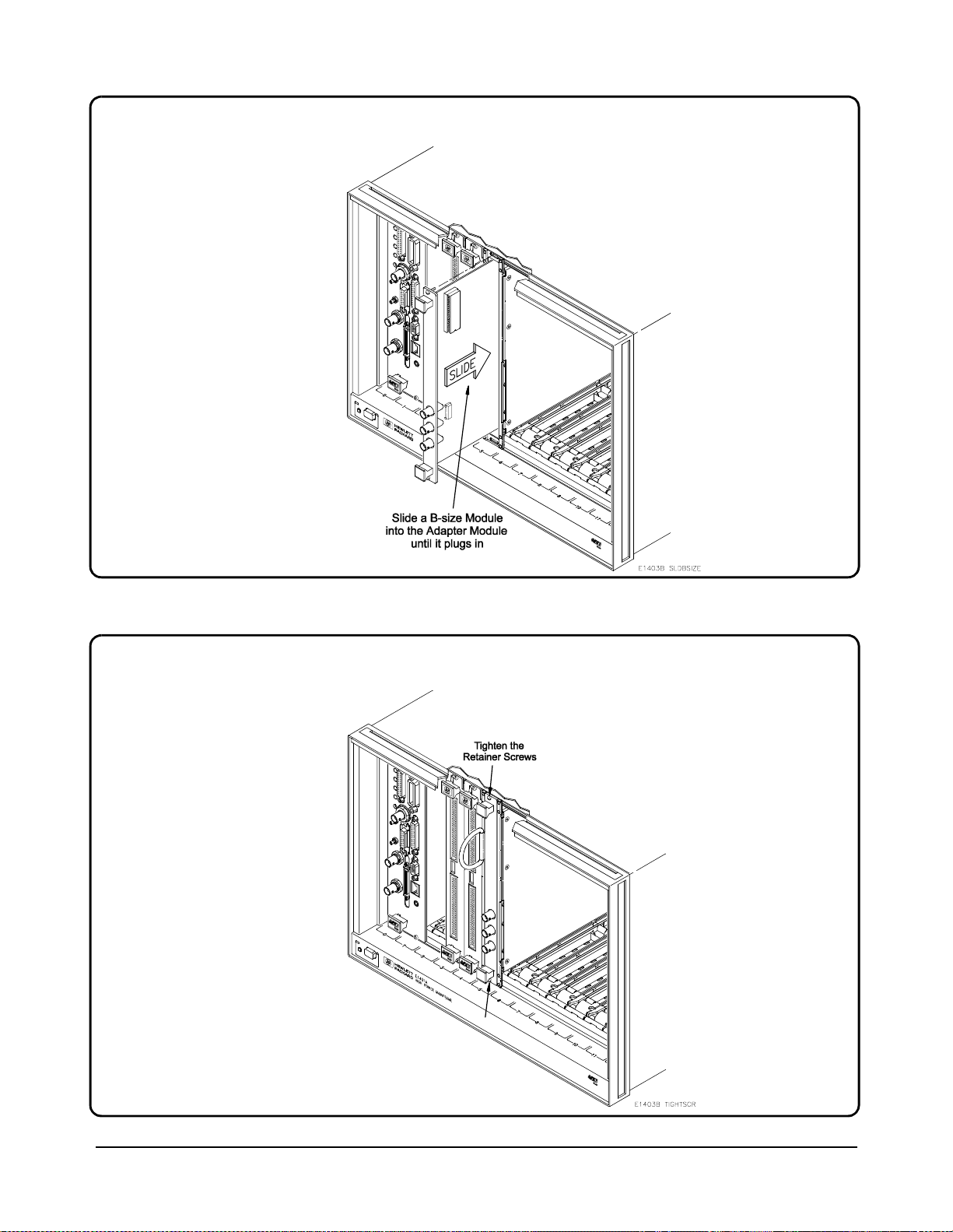
Slide the B-Size Module into the C-Size Adapter Module.
4
Tighten the B-Size Module’s Upper and Lower Retainer Screws.
5
14 Installation/Removal Instructions Chapter 2
Page 15

Removing the Adapter Module and B-Size Module
The following procedure shows how to remove a B-Size VXIbus Module
from an HP E1403C or HP E1407A C-Size Adapter Module and the adapter
module from the mainframe.
Loosen the Upper and Lower Retainer Screws of the B-Size Module inside the
1
C-Size Adapter Module.
Continued on Next Page
Installation/Removal Instructions 15Chapter 2
Page 16

Using the handles on the B-Size Module, pull the Module out of the C-Size Adapter
2
Module.
NOTE:
When removing the B-size
Module from the Adapter
Module, the Adapter Module
may be pulled out of the
mainframe. If that happens,
carefully pull the B-size Module
out of the Adapter Module,
without damaging any exposed
components on the B-size
Module.
Using the “D” Ring, pull the C-Size Adapter Module out of the Mainframe.
3
16 Installation/Removal Instructions Chapter 2
Page 17
This chapter shows how to use the adapter modules. It includes a block
diagram for both the HP E1403C and HP E1407A Adapter Modules as well
as connector pinouts. This chapter also includes, for the HP E1407A
Adapter Module, instructions on how to use and install the J2 connector
cable, how to select the di rect ion (t o or fro m the mainf rame’s backp lane) of
the trigger signals on the ECL and TTL trigger lines, and how to select
unbuffered or buffered SUMBUS connections.
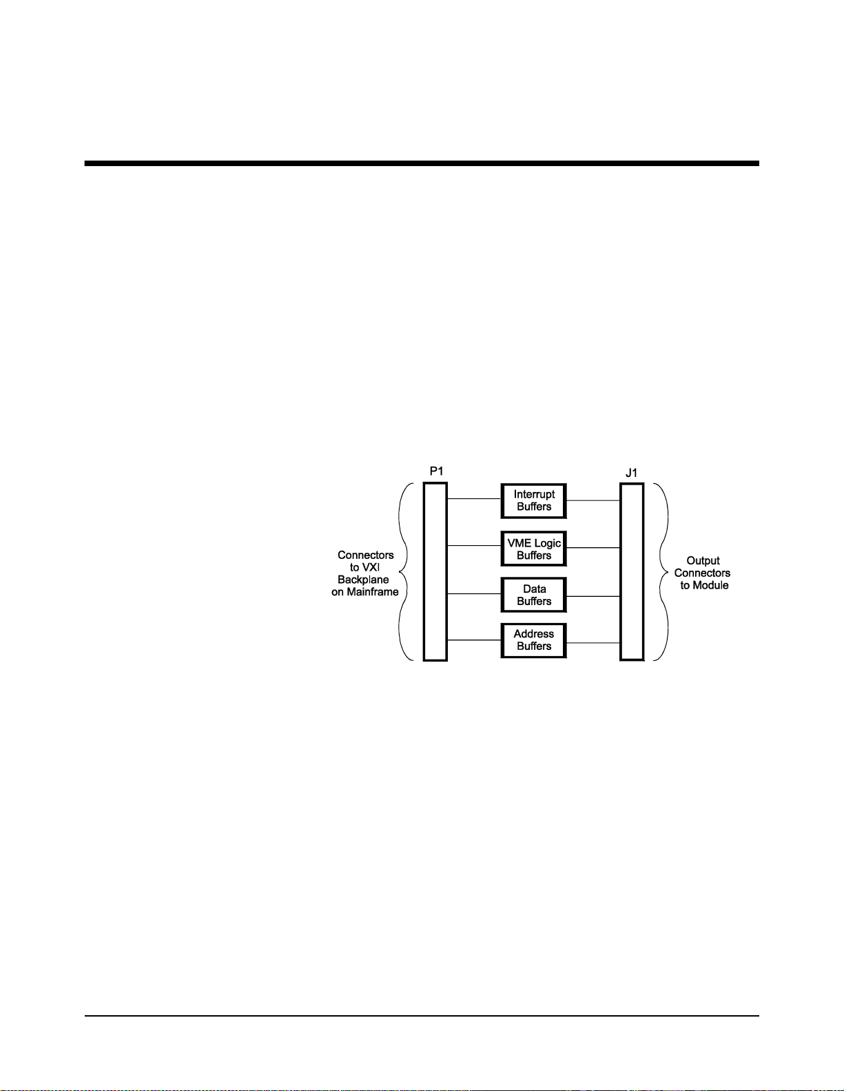
HP E1403C Block Diagram
Figure 3-1 shows the block diagram for the HP E1403C C-Size Adapter
Module.
Chapter 3
Using the Adapters
Figure 3-1. HP E1403C Block Diagram
Using the Adapters 17Chapter 3
Page 18

HP E1403C Connector Pinout
Figure 3-2 shows the P1 and J1 connector’s pinout for the HP E1403C
Adapter Module.
Figure 3-2. HP E1403C P1 and J1 Connector Pinout
18 Using the Adapters Chapter 3
Page 19

HP E1407A Block Diagram
Figure 3-3 shows the block diagram for the HP E1407A C-Size Adapter
Module.
Figure 3-3. HP E1407A Block Diagram
Using the Adapters 19Chapter 3
Page 20

HP E1407A Connector Pinout
Figure 3-4 shows the P1 and J1 connecto r’s pinout, and Figure 3-5 shows the
P2 and J2 connector’s pinout for the HP E1407A Adapter Module.
Figure 3-4. HP E1407A P1 and J1 Connector Pinout
Figure 3-5. HP E1407A P2 and J2 Connector Pinout
20 Using the Adapters Chapter 3
Page 21

Installing the J2 Connector Cable (HP E1407A Only)
Purpose of the
J2 Cable
Caution Damage to a VMEbus module, adapter module, mainframe, or
The HP E1407A C-Size Adapter Module is shipped with a lo ng and short J2
Connector Cables. The long J2 cable allows for direct access to the outer
rows of the J2 connector of the B-Size module (that is, VMEbus modules
that utilize the outer rows of J2) inside the adapter module. The short J2
cable makes internal connections between the P2 and J2 connectors of the
adapter module to allow for connections between the J2 connector of the
B-Size module inside the adapter module and the P2 connector of the
mainframe. Us e this for VXIbus modules that utilize the outer rows of J2.
If your module has no outer row connections of J2, do not install either
cable.
See Figure 3-6 for the J2 connector’s pinout diagra m.
all three may result if using the short cable in an adapter
module with a VMEbus module.
Install the J2 Cable Do the following to in stall either J2 Cable:
On the C-Size VXIbus Adapter Module, remove the 7 Top Shield Retainer Screws
1
and Top Shield.
Using the Adapters 21Chapter 3
Page 22

Plug in either the Short or Long Ribbon (J2) Cable.
2
Reinstall the Top Shield and Retainer Screws on the C-Size Adapter Module.
3
22 Using the Adapters Chapter 3
Page 23

Ribbon Cable (J2)
Connector Pinout
Figure 3-6 shows the pinout for the HP E1407A ribbon cable connectors
(J2).
Figure 3-6. HP E1407A Ribbon Cable Connectors (J2)
Using the Adapters 23Chapter 3
Page 24

Selecting the TTL Trigger Direction (HP E1407A Only)
The HP E1407A C-Size Adapter Module has a swit ch that allows yo u to set
the trigger signal direction of the TTL0–TTL7 Trigger Lines. Figure 3-7
shows that the TTL7 Trigger Signal comes from the B-Size Module, and
TTL0–TTL6 from the Mainframe's VXI Backplane. Use the illu stration as
a guide to set the appropriate trigger directions for your application.
Figure 3-7. Selecting the TTL Trigger Signal Direction
24 Using the Adapters Chapter 3
Page 25

Selecting the ECL Trigger Direction (HP E1407A Only)
The HP E1407A C-Size Adapter Module has a swit ch that allows yo u to set
the trigger signal di rection of the ECL0 and ECL1 Trigge r Lines. Figure 3-8
shows that the ECL1 Trigger Signal comes from the B-Size Module, and
ECL0 from the Mainframe’s VXI Backpl ane. Use the ill ustration as a guide
to set the appropriate trigger directions for your application.
Figure 3-8. Selecting the ECL Trigger Signal Direction
Using the Adapters 25Chapter 3
Page 26

SUMBUS Configurations (HP E1407A Only)
Disconnecting
the SUMBUS
The ribbon cable and a p ai r of jumpers connect the SUMBUS to the ou tput
connectors (i.e., to the B-Size Module). Use Figure 3-9 to disconnect
(i.e., remove the jumpers) or connect the SUMBUS.
Figure 3-9. SUMBUS Jumper Configurations
Adding Buffer
Circuitry to the
SUMBUS
26 Using the Adapters Chapter 3
The adapter module has no circuitry available to buffer the SUMBUS.
However, there is a breadboard area on the PC board in the HP E1407A
Adapter that allows you to add you r own circuitr y (e.g., op-amps) to provide
buffering for the SUMBUS. The b readboard ar ea also in cludes connec tions
to the ±12V Power Supplies.
You can add buffer circuitry either for SUMBUS signals coming from the
B-Size Module in the Adapter Module or from the Mainframe’s VXI
Backplane. Use Figure 3-9 to select the appropriate jumpers for your
application, and to locate the breadboard area.
Page 27

Appendix A
HP E1403C and HP E1407A Specifications
Product Characteristics
•P1 and P2 extension fully buffered (P1 only on HP E1403C).
•Slave-only capability; cannot be used in Slot 0 with bus masters.
•Unlimited number of adapters per mainframe.
•1-slot wide.
•Option 10 is 2-slot wide. Only the P1 and/o r P2 conne ctors of a si ngle
slot are used.
•Replacement fuses are subminiature 4A, 125V
(Littelfuse is recommended).
Power Requirements
Cooling Requirement s
0.02mm H2O @0.10Liter/sec Air Flow for 10°C rise.
Voltage:
Peak Module Current (A): 0.10 0.07
Dynamic Module Current (A): 0.01 0.01
* HP E1407A Only
+5V +12V*
HP E1403C and HP E1407A Specifications 27Appendix A
Page 28

Notes:
28 HP E1403C and HP E1407A Specifications Appendix A
Page 29

Index
A
Adapter Description, 9
HP E1403C, 9
HP E1407A, 10
option 10, 9
Adding SUMBUS Buffer Circuitry, 26
A-Size VMEbus Modules, installing, 11
B
Backplane
ECL trigger signals, 25
SUMBUS buffer circuitry, 26
TTL trigger signals, 24
Block Diagram
HP E1403C, 17
HP E1407A, 19
B-Size VXIbus Modules
ECL trigger signal, 25
installing, 12–14
removing, 15–16
SUMBUS buffer circuitry, 26
TTL trigger signal, 24
C
Cable
ribbon cable (J2)
description, 21
installing, 21, 23
pinouts, 23
Certification, 3
Connecting the SUMBUS, 26
Cooling Requirements, 27
D
Declaration of Conformity, 5
Description
adapters, 9
HP E1403C, 9
HP E1407A, 10
ECL trigger, 25
ribbon cable (J2), 21, 23
SUMBUS, 26
TTL trigger, 24
option 10, 9
ribbon cable (J2), 21, 23
Disconnecting the SUMBUS, 26
Documentation History, 4
E
ECL Trigger Direction, 25
F
Fuses, 27
H
HP E1403C
A-size VMEbus modules
installing, 11
block diagram, 17
B-size VXIbus modules
installing, 12–14
removing, 15–16
description, 9
pinout, 18
specifications, 27
HP E1407A
block diagram, 19
B-size VXIbus modules
ECL trigger signals, 25
installing, 12–14
removing, 15–16
SUMBUS buffer circuitry, 26
TTL trigger signals, 24
description, 10
ECL trigger direction, 25
pinout, 20
ribbon cable (J2), 23
ribbon cable (J2), installing, 21, 23
specifications, 27
SUMBUS, 26
TTL trigger direction, 24
Index 29
Page 30

I
Installation
and removal instructions, 11
A-size VMEbus modules, 11
B-size VXIbus modules, 12–14
HP E1407A, ribbon cable (J2), 21, 23
preparation, 11
M
Mainframe
backplane
ECL trigger signals, 25
SUMBUS buffer circuitry, 26
TTL trigger signals, 24
installing
A-size VMEbus modules, 11
B-size VXIbus modules, 12–14
removing modules from, 15–16
O
Option 10, description, 9
Switches
ECL trigger, 25
TTL trigger, 24
T
Triggers
B-size modules, 24–25
ECL, 25
mainframe VXI backplane, 24–25
TTL, 24
TTL Trigger Direction, 24
U
Using the Ada pters, 17
W
WARNINGS, 4
P
Pinouts
HP E1403C, 18
HP E1407A, 20
ribbon cable (J2), 23
Power Requirements, 27
Preparing for Installation, 11
R
Removing B-size VXIbus Modules, 15–16
Ribbon Cable (J2)
description, 21
installing, 21, 23
pinouts, 23
S
Safety Warnings, 4
Selecting
ECL trigger direction, 25
TTL trigger direction, 24
Specifications, 27
SUMBUS
adding buffer circuitry, 26
configurations, 26
30 Index
 Loading...