

Page 1

Contents
HP E1330B Quad 8-Bit Digital I/O User’s Manual
Edition 7
Warranty ................................................ ......... ......... ......... ......... ......... ......... ......... ........5
Safety Symbols.............................................................................................................6
WARNINGS.................................................................................................................6
Declaration of Conformity............................................................................................7
Reader Comment Sheet ................................................................................................9
Chapter 1
Getting Started .............................................................................................................11
Using This Chapter.....................................................................................................11
Technical Description.................................................................................................11
Instrument Definition..................................................................................................13
Downloading SCPI Drivers........................................................................................13
Programming the Digital I/O Module.........................................................................13
SCPI Command Format Used in This Manual ....................................................14
Specifying SCPI Commands ...............................................................................14
Initial Operation..........................................................................................................16
Chapter 2
Configuring the HP E1330B Digital I/O Module ......................................................17
Using This Chapter.....................................................................................................17
Setting the Address Switch.........................................................................................18
Enabling Pull-ups........................................................................................................19
Selecting the Interrupt Line ........................................................................................20
Combining the Flag Lines...........................................................................................21
Digital I/O Module Peripheral Pinout.........................................................................22
Configuring for Isolated Digital I/O...........................................................................25
Connecting to a GPIO Peripheral ...............................................................................26
Using with External Pull-ups......................................................................................28
Typical Connection.....................................................................................................29
Chapter 3
Using the HP E1330B Digital I/O Module .................................................................31
Using This Chapter.....................................................................................................31
Addressing the Module...............................................................................................31
Operation Overview....................................................................................................32
Default and Reset States.............................................................................................33
Setting the Polarity......................................................................................................33
Setting the Handshake Mode......................................................................................34
Handshake Timing ..............................................................................................34
Inputting Data Bytes and Bits.....................................................................................35
Input ....................................................................................................................35
Outputting Data Bytes and Bits..................................................................................36
Output ..................................................................................................................36
Multiple Port Operations ............................................................................................37
Using Trace Memory..................................................................................................38
Contents 1
Page 2

Chapter 4
Understanding the HP E1330B Digital I/O Module .................................................41
Using This Chapter.....................................................................................................41
Port Description..........................................................................................................41
Data Lines .......................................................................... ......... ........................41
The FLG Line (Input) ..........................................................................................42
The CTL Line (Output) .......................................................................................42
The I/O Line (Output) .........................................................................................42
The STS Line ......................................................................................................43
The PIR Line .......................................................................................................43
The RES Line ......................................................................................................43
Default and Reset States.............................................................................................43
Setting the Polarity......................................................................................................43
Using the Handshake Modes......................................................................................44
Handshake Modes ...............................................................................................45
Inputting Data Bytes and Bits.....................................................................................50
Bit Input ...............................................................................................................50
Byte Input ............................................................................................................50
Outputting Data Bytes and Bits..................................................................................51
Bit Output ............................................................................................................51
Byte Output .........................................................................................................52
Multiple Port Operations ............................................................................................53
Multiple Port Handshaking .................................................................................53
Multiple Port Input/Output ..................................................................................54
Chapter 5
HP E1330B Digital I/O Module Command Reference .............................................57
DISPlay Subsystem.....................................................................................................61
:MONitor:PORT ..................................................................................................61
:MONitor:PORT? ................................................................................................ 62
:MONitor[:STATe] ............................................................................................. 62
:MONitor[:STATe]? ............................................................................................63
MEASure Subsystem..................................................................................................64
:DIGital:DATAn[:type]:BITm? ..........................................................................64
:DIGital:DATAn[:type]:TRACe ......................................................................... 65
:DIGital:DATAn[:type][:VALue]? ..................................................................... 66
:DIGital:FLAGn? ................................................................................................67
MEMory Subsystem...................................................................................................68
:DELete:MACRo ................................................................................................68
:VME:ADDRess ..................................................................................................69
:VME:ADDRess? ................................................................................................ 69
:VME:SIZE .........................................................................................................70
:VME:SIZE? ........................................................................................................70
:VME:STATe ...................................................................................................... 71
:VME:STATe? .................................................................................................... 71
[SOURce:] Subsystem................................................................................................72
DIGital:CONTroln:POLarity .............................................................................. 74
DIGital:CONTroln:POLarity? ............................................................................74
2 Contents
Page 3

DIGital:CONTroln[:VALue] ..............................................................................75
DIGital:CONTroln[:VALue]? .............................................................................75
DIGital:DATAn[:type]:BITm ............................................................................. 76
DIGital:DATAn[:type]:BITm? ...........................................................................77
DIGital:DATAn[:type]:HANDshake:DELay .....................................................78
DIGital:DATAn[:type]:HANDshake:DELay? ....................................................79
DIGital:DATAn[:type]:HANDshake[:MODE] ..................................................80
DIGital:DATAn[:type]:HANDshake[:MODE]? .................................................81
DIGital:DATAn[:type]:POLarity ........................................................................ 82
DIGital:DATAn[:type]:POLarity? ...................................................................... 82
DIGital:DATAn[:type]:TRACe ..........................................................................83
DIGital:DATAn[:type][:VALue] ........................................................................ 84
DIGital:DATAn[:type][:VALue]? ......................................................................85
DIGital:FLAGn:POLarity ................................................................................... 86
DIGital:FLAGn:POLarity? .................................................................................86
DIGital:HANDshaken:DELay ............................................................................87
DIGital:HANDshaken:DELay? ..........................................................................88
DIGital:HANDshaken[:MODE] .........................................................................88
DIGital:HANDshaken[:MODE]? ........................................................................89
DIGital:IOn? ........................................................................................................89
DIGital:TRACe:CATalog? .................................................................................90
DIGital:TRACe[:DATA] ....................................................................................90
DIGital:TRACe[:DATA]? ..................................................................................91
DIGital:TRACe:DEFine ......................................................................................91
DIGital:TRACe:DEFine? .................................................................................... 92
DIGital:TRACe:DELete:ALL .............................................................................92
DIGital:TRACe:DELete[:NAME] ...................................................................... 92
STATus Subsystem.....................................................................................................93
:OPERation:CONDition? .................................................................................... 94
:OPERation:ENABle ...........................................................................................94
:OPERation:ENABle? .........................................................................................94
:OPERation[:EVENt]? ........................................................................................ 94
:PRESet ............................................................................................................... 94
:QUEStionable:CONDition? ...............................................................................95
:QUEStionable:ENABle ......................................................................................95
:QUEStionable:ENABle? .................................................................................... 95
:QUEStionable[:EVENt]? ................................................................................... 95
SYSTem Subsystem ...................................................................................................96
:CDEScription? ................................................................................................... 96
:CTYPe? .............................................................................................................. 96
:ERRor? ............................................................................................................... 97
:VERSion? ...........................................................................................................97
Appendix A
HP E1330B Digital I/O Specifications ......................................................................103
Appendix B
HP E1330B Digital I/O Module Register Information ...........................................105
Contents 3
Page 4

Using This Appendix................................................................................................105
Addressing the Registers..........................................................................................105
The Base Address ..............................................................................................106
Register Offset ...................................................................................................108
Reset and Registers ...................................................................................................109
Register Definitions..................................................................................................109
Register Descriptions................................................................................................111
Manufacturer Identification Register ................................................................111
Device Identification Register ...........................................................................111
Card Status/ Control Register ............................................................................111
Port Interrupt Control Register ..........................................................................112
Port Transfer Control Register ..........................................................................113
Port Control/ Status Register .............................................................................114
Port Data Register .............................................................................................115
Port Handshake Register ...................................................................................116
Port Delay Register ...........................................................................................117
Port Normalization Register ..............................................................................118
A Register-Based Output Algorithm ........................................................................118
A Register-Based Input Algorithm...........................................................................120
Programming Examples............................................................................................121
System Configuration ........................................................................................121
Resetting the Module ......................................................... ......... ......................122
Reading the ID, Device Type, and Status Registers .........................................123
Writing an 8-Bit Byte ........................................................................................125
Writing a 16-Bit Word ......................................................................................127
Reading an 8-Bit Byte .......................................................................................128
Reading a 16-Bit Word .....................................................................................130
Debugging Basic Register-
Based Programs .................................................................................................130
PIR Interrupts on the HP E1330 ........................................................................131
HP E1330B Non-data Line I/O .........................................................................136
Embedded Computer Example ..........................................................................140
4 Contents
Appendix C
Error Messages ..........................................................................................................143
Index ..............................................................................................................................145
Page 5

Certification
Hewlett-Packard Company certifies that this product met its published specifications at the time of shipment from the factory. HewlettPackard further certifies that its calibration measurements are traceable to the United States National Institute of Standards and
Technology (formerly National Bureau of Standards), to the extent allowed by that organization’s calibration facility, and to the
calibration facilities of other International Standards Organization members.
Warranty
This Hewlett-Packard product is warranted against defects in materials and workmanship for a period of three years from date of shipment.
Duration and conditio ns of wa rrant y for this p roduc t may be su perseded when th e pro duct is in tegrate d in to (bec omes a part of) other HP
products. During the warranty period, Hewlett-Packard Company will, at its option, either repair or replace products which prove to be
defective.
For warranty service or repai r, this produc t must be return ed to a service facility design ated by Hewlett-Pa ckard (HP). Bu yer sha ll prep ay
shipping charges to HP and HP shall pay shipping charges to return the product to Buyer. However, Buyer shall pay all shipping charges,
duties, and taxes for products returned to HP from another country
HP warrants that its software and firmware designated by HP for use with a product will execute its programming instructions when
properly installed on that product. HP does not warrant that the operation of the product, or software, or firmware will be uninterrupted
or error free.
Limitation Of Warranty
The foregoing warranty sh all not apply to defects resu lting from im proper or ina dequate ma intenance by Buyer, Bu yer-supplie d products
or interfacing, unauthorized modification or misuse, operation outside of the environmental specifications for the product, or improper
site preparation or ma intenance.
The design and implementation of any circuit on this product is the sole responsibility of the Buyer. HP does not warrant the Buyer’s
circuitry or malfunctions of HP products that result from the Buyer’s circuitry. In addition, HP does not warrant any damage t hat occurs
as a result of the Buyer’s circuit or any defects that result from Buyer-supplied products.
NO OTHER WARRANTY IS EXPRESSED OR IMPLIED. HP SPECIFICALLY DISCLAIMS THE IMPLIED WARRANTIES OF
MERCHANTABILITY AND FITNESS FOR A PARTICULAR PURPOSE.
Exclusive Remedies
THE REMEDIES PROVIDED HEREIN ARE BUYER’S SOLE AND EXCLUSIVE REMEDIES. HP SHALL NOT BE LIABLE FOR
ANY DIRECT, INDIRECT, SPECIAL, INCIDENTAL, OR CONSEQUENTIAL DAMAGES, WHETHER BASED ON CONTRACT,
TORT, OR ANY OTHER LEGAL THEORY.
Notice
The information contained in this document is subject to change without notice. HEWLETT-PACKARD (HP) MAKES NO
WARRANTY OF ANY KIND WITH REGARD TO THIS MATERIAL, INCLUDING, BUT NOT LIMITED TO, THE IMPLIED
WARRANTIES OF MERCHANTABILITY AND FITNESS FOR A PARTICULAR PURPOSE. HP shall not be liable for errors
contained herein or for incidental or consequential damages in connection with the furnishing, perf ormance or use of this material. This
document contains proprietary information which is protected by copyright. All rights are reserved. No part of this document may be
photocopied, reproduced, or translated to another language without the prior written consent of Hewlett-Packard Company. HP assumes
no responsibility for the use or reliability of its software on equipment that is not furnished by HP.
U.S. Government Restricted Rights
The Software and Documentation have been developed entirely at private expense. They are delivered and licensed as "commercial
computer software" as defined in DFARS 252.227- 7013 (Oct 1988), DFARS 252.211-7015 (May 1991) or DFARS 252.227-7014 (Jun
1995), as a "commercial item" as defined in FAR 2.101(a), or as "Restricted computer software" as defined in FAR 52.227-19 (Jun
1987)(or any equivalent agency regulation or contract clause), whichever is applicable. You have only those rights provided for such
Software and Documentation by the applicable FAR or DFARS clause or the HP standard software agreement for the product involved
HP E1330B Quad 8-Bit Digital I/O User’s Manual
Edition 7
Copyright © 1997 Hewlett-Packard Company. All Rights Reserved.
5
Page 6
Documentation History
All Editions and Updates o f this manu al and t heir cre ation da te are li sted belo w. The first Edi tion o f the m anual i s Edition 1. The Edition
number increments by 1 whenever the manual is revised. Updates, which are issued between Editions, contain replacement pages to
correct or add additional information to the current Edition of the manual. Whenever a new Edition is created, it will contain all of the
Update information for the previous Edi tion. Each ne w Edition or Upd ate also incl udes a revised copy of this d ocumentation h istory page.
Edition 1 . . . . . . . . . . . . . . . . . . . . . . . . . . . . . . . . . . . . . . . . . . . . . . . . . . . . . . . .
Edition 2 . . . . . . . . . . . . . . . . . . . . . . . . . . . . . . . . . . . . . . . . . . .September 1990
Edition 3 . . . . . . . . . . . . . . . . . . . . . . . . . . . . . . . . . . . . . . . . . . . . . . . April 1992
Edition 4 . . . . . . . . . . . . . . . . . . . . . . . . . . . . . . . . . . . . . . . . . . .September 1992
Edition 5 . . . . . . . . . . . . . . . . . . . . . . . . . . . . . . . . . . . . . . . . . . .November 1993
Edition 6 . . . . . . . . . . . . . . . . . . . . . . . . . . . . . . . . . . . . . . . . . . . . . . . .June 1995
Edition 7 . . . . . . . . . . . . . . . . . . . . . . . . . . . . . . . . . . . . . . . . . . . . . . . .May 1997
Safety Symbols
Instruction manual symbol affixed to
Instruction manual symbol affixed to
product. Indicates that the user must refer to
product. Indicates that the user must refer to
the manual for specific WARNING or
the manual for specific WARNING or
CAUTION information to avoid personal
CAUTION information to avoid personal
injury or damage to the product.
injury or damage to the product.
Indicates the field wiring terminal that must
be connected to earth ground before
operating the equipme nt—protects against
electrical shock in case of fault.
WARNING
Alternating current (AC)
Direct current (DC).
Indicates hazardous voltages.
Calls attention to a procedure, practice , or
condition that could cause bodily injury or
death.
or
Frame or chassis ground terminal—typically
connects to the equipment' s metal frame.
CAUTION
Calls attention to a procedure, practice , or
condition that could p ossibly cause damage to
equipment or permane nt loss of data.
WARNINGS
The following genera l safety precautions must be observed during all phas es of operation, service, and re pair of this product. Failure to
comply with these precautions or with specific warnings elsewhere in this manual violates safety standards of design, manufacture, and
intended use of the product. Hewlett-Packar d Company assumes no liabilit y for the customer's failu re to comply with these requirements.
Ground the equipment: For Safety Class 1 equipment (equipment having a protective earth terminal), an uninterruptible safety earth
ground must be provided from the mains power source t o the product input wiring terminals or supplied power cable.
DO NOT operate the product in an explosive atmosphere or in the presence of flammable gases or fumes.
For continued protection against fire, replace the line fuse(s) only with fuse(s) of the same voltage and current rating and type. DO NOT
use repaired fuses or short-circuited fuse holders.
Keep away from live circuits: Operating personnel must not remove equipment covers or shields. Procedures involving the removal of
covers or shields are for use by service-trained personnel only. Under cer tain conditions, dangerous voltages may exist even w ith the
equipment swi tched off . To avoid da ngerous el ectrica l shock, DO N OT perform procedure s involvin g cover or sh ield remova l unless you
are qualified to do so.
DO NOT operate damaged equipmen t: Whenever it is possible that the safety protection features built into this product have been
impaired, either through physical damage, excessive moisture, or any other reason, REMOVE POWER and do not use the product until
safe operation can be verified by service-trained personnel. If necessary, return the product to a Hewlett-Packard Sales and Service Office
for service and repair to ensure that safety features are maintained.
DO NOT service or adjust alone: Do not attempt internal service or adjustment unless another person, capable of rendering first aid and
resuscitation, is present.
DO NOT substitute parts or modify equipment: Because of the dange r of introd ucing addi tional h azards, do not install substitute parts
or perform any unauthorized mod ification to the product. Return the product t o a Hewl ett-Packard Sales and Service Office for service
and repair to ensure that safety features are maintained.
6
Page 7

Declaration of Conformity
according to ISO/IEC Guide 22 and EN 45014
Manufacturer’s Name: Hewlett-Packard Company
Loveland Manufacturing Center
Manufacturer’s Address: 815 14th Street S.W.
Loveland, Colorado 80537
declares, that the product:
Product Name: Quad 8-Bit Digital I/O Module
Model Number: HP E1330B
Product Options: All
conforms to the following Product Specifications:
Safety: IEC 1010-1 (1990) Incl. Amend 1 (1992)/EN61010-1 (1993)
CSA C22.2 #1010.1 (1992)
UL 1244
EMC: CISPR 11:1990/EN55011 (1991): Group 1 Class A
EN50082-1:1992
IEC 801-2:1991: 4kVCD, 8kVAD
IEC 801-3:1984: 3 V/m
IEC 801-4:1988: 1kV Power Line, .5kV Signal Lines
Supplementary Information: The product herewith complies with the requirements of the Low Voltage Directive
73/23/EEC and the EMC Directive 89/336/EEC (inclusive 93/68/EEC) and carries the "CE" marking acco rdingly.
Tested in a typical configuration in an HP B-Size VXI mainframe.
June 15, 1995
European contact: Your local Hewlett-Packard Sales and Service Office or Hewlett-Packard GmbH, Depart-
ment HQ-TRE, Herrenberger Straße 130, D-71034 Böblingen, Germany (FAX +49-7031-14-3143)
Jim White, QA Manager
7
Page 8

Notes:
8
Page 9
Pl
ease fold and tape for ma
ili
ng
Reader Comment Sheet
HP E1330B Quad 8-Bit Digital I/O User’s Manual
Edition 7
You can help us improve our manuals by sharing your comments and sug gestions . In appreciation of your time, we will
enter you in a quarterly drawing for a Hewlett-Packard Palmtop Personal Computer (U.S. government employees
are not eligible for the drawing).
Your Name
Company Name
Job Title
Address
City, State/Province
Country
Zip/Postal Code
Telephone Number with Area Code
Please list the system controller, operating system, programming language, and plug-in modules you are using.
fold here
BUSINESS REPLY MAIL
FIRST CLASS PERMIT NO. 37 LOVELAND, CO
POSTAGE WILL BE PAID BY ADDRESSEE
cut along this li ne
HEWLETT-PACKARD COMPANY
Measurement Systems Division
Learning Products Department
P.O. Box 301
Loveland, CO 80539-9984
NO POSTAGE
NECESSARY
IF MAILED
IN THE
UNITED STATES
fold here
Please pencil-in one circle for each statement below: Disagree Agree
• The documentation is well organized. OOOOO
Instructions are easy to understand. OOOOO
•
The documentation is clearly written. OOOOO
•
•Examples are clear and useful. OOOOO
Illustrations are clear and helpful. OOOOO
•
The documentation meets my overall expectations. OOOOO
•
Please write any comments or suggestions below–be specific.
Page 10

Page 11
Using This Chapter
This chapter describes the Quad 8-bit Digital I/O Module and how to
program the Module using SCPI (Standard Commands for Programmable
Instruments) commands. This chapter contains the following sections:
• Technical Description . . . . . . . . . . . . . . . . . . . . . . . . . . . . . . page 11
• Instrument Definition . . . . . . . . . . . . . . . . . . . . . . . . . . . . . . page 13
• Downloading SCPI Drivers . . . . . . . . . . . . . . . . . . . . . . . . . page 13
• Programming the Digital I/O Module. . . . . . . . . . . . . . . . . . page 13
• Initial Operation . . . . . . . . . . . . . . . . . . . . . . . . . . . . . . . . . . page 16
Technical Description
The HP E1330B Quad 8-Bit Digital I/O Module (referred to as the Digital
I/O module) is a four port digital input/output module intended for data
communication and digital control in electronic environments. The Digital
I/O module is compatible with TTL levels (0-5V) or CMOS levels (using
external pull-ups). The Digital I/O module complies wi th VXIbus (VMEbus
Extensions for Instrumentation) definitions for the P1 bus connector on
B-sized modules. A jumper on the module sets the VXIbus interrupt level.
Chapter 1
Getting Started
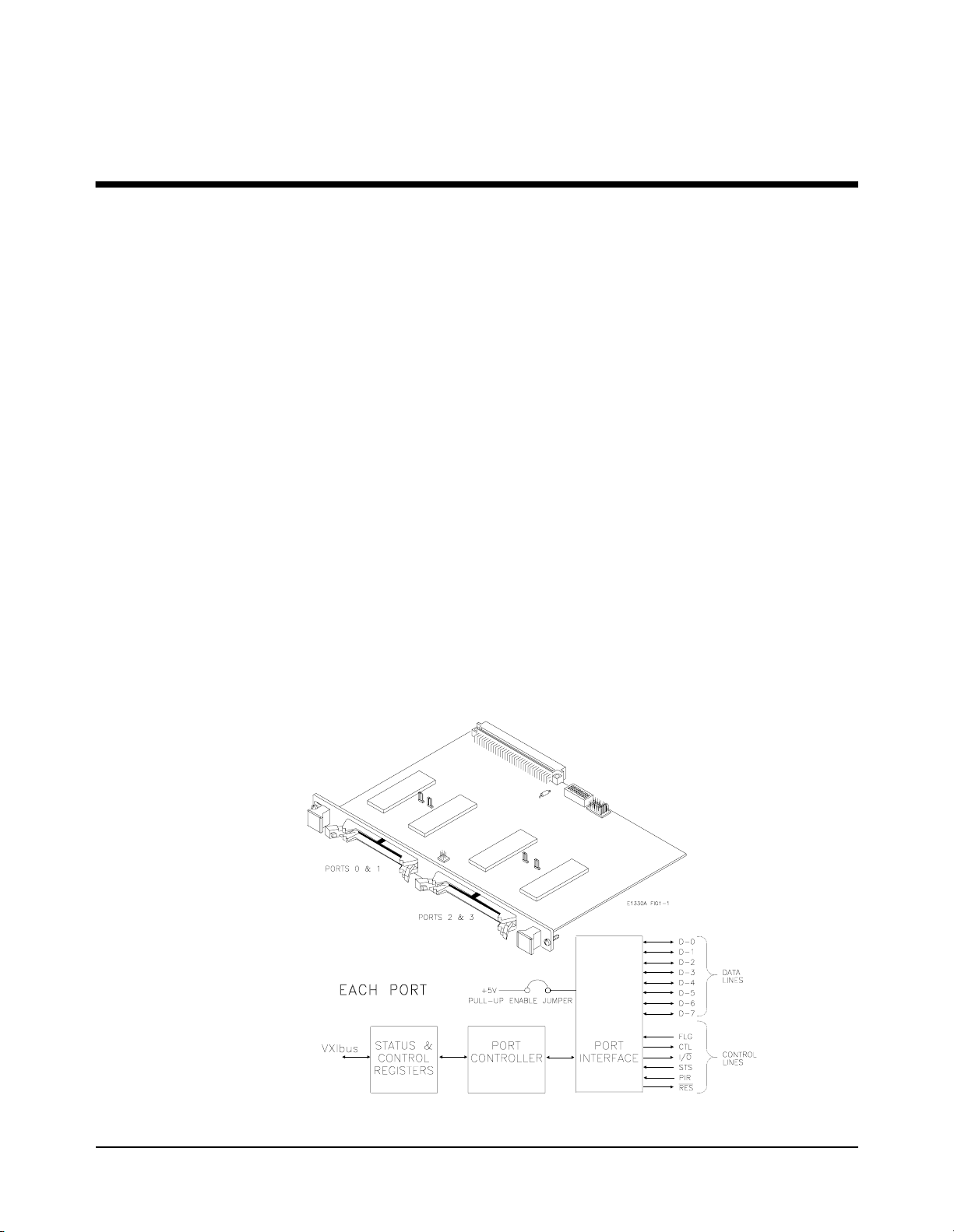
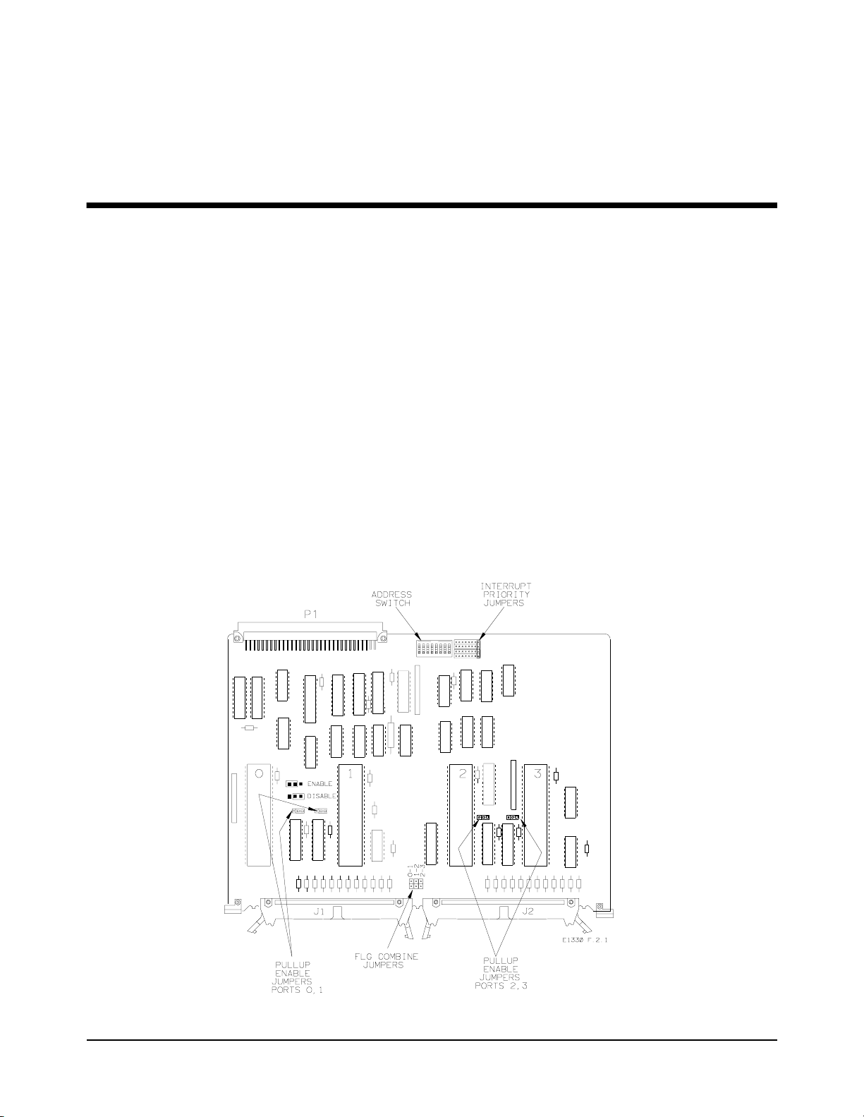
Figure 1-1. HP E1330B Digital I/O Module
Getting Started 11Chapter 1
Page 12
Each port is identical and con si st s of 6 cont ro l lines and 8 data lines. There
are 7 registers for control and status on each port. In addition, the module
also has Manufacturer ID, Device Type, and Module Status/Control
Registers. Figure 1-1 shows the locations of the ports and a simplified
diagram of a single port. Of the seven control lines, three (I/O
FLG) are used with SCPI commands and three (RES
, STS, and PIR) are
, CTL, and
controlled through register access. Chapter 4 — “Understanding the
HP E1330B Digital I/O Module” contains detailed descriptions of these
lines.
Each port has two sets of hardware configuration jumpers. One set of
jumpers allows you to connect th e FLG lines together for multi-port dat a
transmission. Another jumper selects either open collector operation or
internal pull-up to TTL compatible levels on the data lines. Chapter 2 —
“Configuring the HP E1330B Digital I/O Module” describes how to set
these jumpers.
SCPI commands provided for the Digital I/O allow opera tion on a singl e bit,
8-bit "BYTE" format, 16-bit "WORD" format (using 2 ports), or 32-bit
"LWORd" format (using 4 ports).
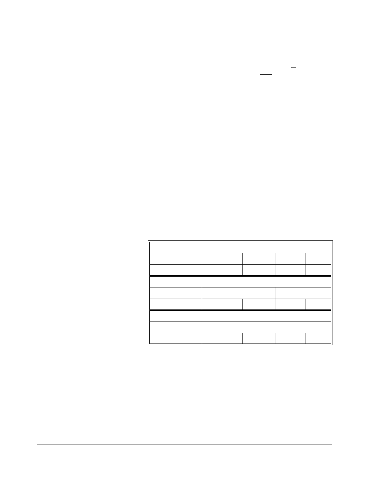
Figure 1-1 shows the mapping of bit numbers from the 8-bit ports to the
16- or 32-bit ports. Chapter 5 — “HP E1330B Digital I/O Command
Reference” describes each command in detail and Chapter 3 — “Using the
HP E1330B Digital I/O Module” gives examples of the use of SCPI
commands.
Table 1-1. Data Lines
8-bit (BYTE) Operations
Port # 0 1 2 3
Bit designations 7------0 7------0 7------0 7------0
16-bit (WORD) Operations
Port # 0 2
Bit designations 15------8 7------0 15------8 7------0
32-bit (LWORd) Operations
Port # 0
Bit designations 31------24 23------16 15------8 7------0
Two 3-meter, 60-wire ribbon cabl es with an insulation displacement hea der
connector (ribbon cable c onnector) on o ne end a re incl uded with the Dig ital
I/O module. Additional cable sets can be ordered (HP part number
E1330-61601) from your nearest Hewlett-Packard Sales Office.
12 Getting Started Chapter 1
Page 13

Instrument Definition
Each Digital I/O module installed in an HP mainframe is treated as an
independent instrument; having a unique secondary HP-IB address. Each
instrument is also assig ned a dedicated error queue, inpu t and output buffers,
status registers and, if ap plicable, dedicated mainframe memory space for
readings or data. Multiple Digital I/O modules cannot be combined into a
single instrument.
Downloading SCPI Drivers
The HP Digital I/O Driver allows the HP E1330B module to operate with
either B-size mainframes or HP E1405/06 Command Modules in a C-size
mainframe. The driver implements the Stan dard Commands for
Programmable Instrumentation (SCPI) command language. The B-size
HP E1300/E1301 Mainframe has a bui lt in driver, or can use a downloa dable
driver. The two driver s are slightl y differ ent and the diff erences are de tailed
in Chapter 5 — “HP E1330B Digital I/O Command Reference”.
To use the HP E1330B with a C- size mainframe and command module, you
must use a downloadable driver. The downloadable driver name for the
Digital I/O module is “DIG_IO”. The procedure for downloading the drivers
is contained in the HP E1405B and HP E1406A Command Module User
Guides.
Programming the Digital I/O Module
To program the Digital I/O module us ing SCPI commands, you will nee d to
know the controller language and int erface a ddresses you will be using. See
the HP 75000 Series B or Series C Installation and Getting Started Guide
for detailed interface addressing and controller language information.
Note This discussion applies only to SCPI (Standard Commands for
Programmable Instruments ) programming. See Append ix B — “Digital I/O
Register Information” for details on register addressing. Do not mix SCPI
programming and direct register access.
Getting Started 13Chapter 1
Page 14

SCPI Command
Format Used in This
Manual
SCPI commands can be used in either long or short form. A long form
example is:
DISPlay:MONitor ON
The same command, without the lower case letters, is the short form.
For example:
DISP:MON ON
Either the long form or th e short for m commands ca n be used to perform the
same result. The long and short forms can also be mixed within the same
program code. The commands are case insensitive, either upper or lower
case letters are accepted.
<> is a
Specifying SCPI
Commands
In the command examples shown above, the item enclosed in
parameter required to use the command, however, do not include the
brackets when sending the command. In this example, the parameter input
can be replaced with any one of the following:
allowable values of the parameters are given in Chapter 5 — “HP E1330B
Digital I/O Module Command Reference”. You must include at least one
space between the keywords and the parameter.
Some commands are shown with items enclosed in square brackets (
These are implied or optional items that do not have to be included. For
example, the complete command syntax listing for the first example is:
DISPlay:MONitor[:STATe] <0|1 or OFF|ON>
The item enclosed in brackets, [:STATe], does not have to be i ncluded for the
command to work. Complete descr ip ti ons of the SCPI command language,
syntax, parameter types, and usage are in Chapter 5 of this manual.
SCPI command s related to the Dig ital I/O module use three types of
parameters to specify a port number, a bit number, or a multiple port
combining operation. Each type is briefly described here. Descriptions and
examples of usage can be found in Chapter 3 of this manual.
0, 1, OFF, or ON. The
Specifying a Port The Digi tal I/O module has four identical por ts numbered from 0 to 3. SCPI
commands that relate to a specific port use a specia l parameter to indicate
the port number. For example:
[]).
[SOURce:]DIGital:DATAn <value>
This command writes the parameter
portion of the
the number the last character of the
example, to set all port 2 data lines to logical zero, use the command:
[SOURce:]DIGital:DATA2 0
The value of n may vary for multiple port commands and operations. A
description of multiple port commands is on page 15.
14 Getting Started Chapter 1
DATA keyword. Replace the n with the port number, making
<value> to the port specified by the n
DATA keyword without spaces. For
Page 15

Specifying a Bit Each of the four ports on the module has eight bi-directional data lines,
corresponding to eight programmable data bits. Some SCPI commands
allow you manipulate or read these bits individually. For example:
MEASure:DIGital:DATAn:BITm?
This command reads the state of a bit, specified by m, on port n. The result
will be either 0 or 1, indica ting the current l ogical state of the bit. Replac e m
with the desired bit number, and n with the desired port number, making
each number the last characters of the
spaces. For example, to read bit 7 on port 0, use the following command:
MEASure:DIGital:DATA0:BIT7?
For single ports, the value of m can range from 0 to 7. Some multiple port
operations and commands may allow bit numbers to range from 0 to 31.
DATA and BIT keywords without
Specifying Multiple Port
Operations
The Digital I/O modul e all o ws you to set or read mult ip le por ts or bits with
a single command. For example:
MEASure:DIGital:DATAn[:type]?
This command uses an opti onal keyword, [:type], to specify how many ports
are combined in a single re tur n ed val ue. T he l o wer cas e ke yword
[:type] is
replaced with one of a fixed set o f keywords. For exam ple, to read al l 4 ports
(all 32-bits) as a single returned value, use the command:
MEASure:DIGital:DATA0:LWORd?
Keywords are provided to allow port combin ation s of 16- or 32-bits. Us ing
multiple ports is described in more det ail in Chapter 4 of this manual.
Getting Started 15Chapter 1
Page 16

Initial Operation
Use the following example t o verify init ial operati on. The example first sets
and then queries the polarity of a logical true condition on the port 0 FLG
line. The example uses an HP Ser ies 200/30 0 Computer with HP BASIC as
the programming language. The computer is connected to an HP E1301
Mainframe using the Hewlett-Packard Interface B us (HP-IB)*. The HP-IB
interface select code is 7, the HP-IB primary address is 09, and the HP-IB
secondary address (used to specify the Digital I/O module) is 18. Refer to
the B-Size Installation and Getting Started Guide for more details.
10 ASSIGN @Dio TO 70918
20 DIM Polarity$[3]
30 OUTPUT @Dio;"*RST"
40 OUTPUT @Dio;"*OPC?"
50 ENTER @Dio;Ready
60 OUTPUT @Dio;"SOUR:DIG:FLAG0:POL POS;*OPC?"
70 ENTER @Dio;Ready
80 OUTPUT @Dio;"SOUR:DIG:FLAG0:POL?"
90 ENTER @Dio;Polarity$
100 IF Polarity$ <> "POS" THEN
110 DISP "Polarity Check ERROR"
120 PAUSE
130 ELSE
140 DISP"Polarity set to "&Polarity$
150 END IF
160 OUTPUT @Dio;"SOUR:DIG:F LAG 0 :PO L NEG;*OPC?"
170 ENTER @Dio;Ready
180 OUTPUT @Dio;"SOUR:DIG:F LAG 0 :POL? "
190 ENTER @Dio;Polarity$
200 IF Polarity$ <> "NEG" THEN
210 DISP "Polarity Check ERROR"
220 PAUSE
230 ELSE
240 DISP"Polarity set to "&Polarity$
250 END IF
260 OUTPUT @Dio;"*RST"
270 OUTPUT @Dio;"*OPC?"
280 ENTER @Dio;Ready
290 END
!Sets an I/O path to the module.
!Reset the module.
!Wait for the module to finish.
!Hold here until command is
finished.
!Set POSitive polarity.
!Wait for finish.
!Query the polarity state.
!Get the result.
!Check the result.
!Error discovered.
!Pause on error.
!Set NEGative polarity.
!Wait for finish.
!Query the polarity state.
!Get the result.
!Check the result.
!Error discovered.
!Pause on error.
!Restore the module.
!Wait for the module to finish.
* HP-IB is Hewlett-Packard’s implementation of IEEE Std 488.1-1984.
16 Getting Started Chapter 1
Page 17
Configuring the HP E1330B Digit a l I/O
Using This Chapter
Chapter 2
Module
This chapter shows how to configure the Digital I/O module for use in a
VXIbus mainframe, connect peripheral devices, and configure the module
for operation. Refer to Figure 2-1 for locations of jumpers and switches. This
chapter contains the following sections:
• Setting the Address Switch. . . . . . . . . . . . . . . . . . . . . . . . . . page 18
• Enabling Pull-ups . . . . . . . . . . . . . . . . . . . . . . . . . . . . . . . . . page 19
• Selecting the Interrupt Line. . . . . . . . . . . . . . . . . . . . . . . . . . page 20
• Combining the Flag Lines . . . . . . . . . . . . . . . . . . . . . . . . . . . page 21
• Digital I/O Module Peripheral Pinout. . . . . . . . . . . . . . . . . . page 22
• Configuring for Isolated Digital I/O. . . . . . . . . . . . . . . . . . . page 25
• Connecting to a GPIO Peripheral . . . . . . . . . . . . . . . . . . . . . page 26
• Using with External Pull-ups . . . . . . . . . . . . . . . . . . . . . . . . page 28
• Typical Connection . . . . . . . . . . . . . . . . . . . . . . . . . . . . . . . . page 29
Figure 2-1. HP E1330B Digital I/O Module
Configuring the HP E1330B Digital I/O Module 17Chapter 2
Page 18
Setting the Address Switch
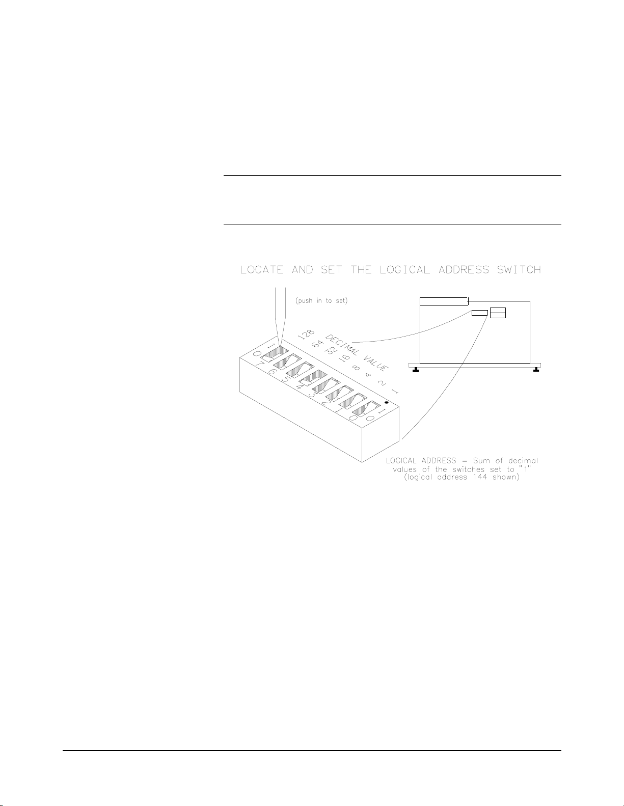
Refer to Figure 2-1. In the center rear of the module, next to the P1
connector, you will fi nd the logical address switch. It s factory sett ing is 144;
rockers 4 and 7 a re closed, all othe rs are open. You can select the addr ess of
the Digital I/O module to any number 0–255 (d eci mal ). The defaul t se tt ing
of the address switch is shown in Figure 2-2.
Note To be recognized as an instrument when you are using the Digital I/O
module in an HP E1300/1301 Mainframe or with an HP E1405 or E1406
Command Module, the logical address must be set to a multiple of 8.
Figure 2-2. Logical Address Switch Set at 144
18 Configuring the HP E1330B Digital I/O Module Chapter 2
Page 19
Enabling Pull-ups
Note The jumper in the enabled posit ion does not add an i nput pull -up res isto r to
Referring to Figure 2-1, note the pull-up enable jumpers near the middle of
each of the large ICs. The data lines of each port can be independently
configured for either passive or active pull-up to TTL high levels. The
factory-shipped condition is pull-up disabled for all ports. The data lines
may be either inputs or outputs. When the data lines are outputs, and the
jumper is in the enabl ed position, the outputs are acti vely forced high. When
the data lines are inputs, the jumper position makes no difference.
each data line, it enables a chip-internal pull-up network.
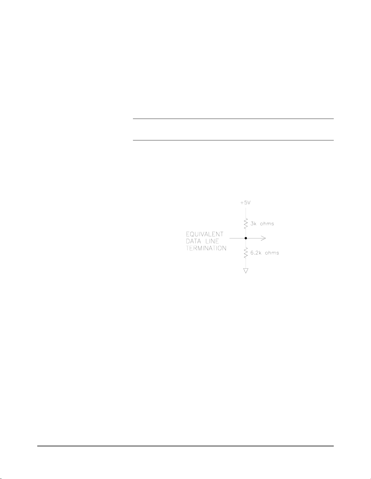
Each data line has an active resistive terminating network. The active
circuitry ensures that when power is removed from the module, the data
lines are not loaded. With power applied, the resistive terminating network
is equivalent to that shown in Figure 2-3.
Figure 2-3. Equivalent Data Line Termination
Configuring the HP E1330B Digital I/O Module 19Chapter 2
Page 20
Selecting the Interrupt Line
The VXI peripheral i nterrupt bus consists o f seven lines which can car ry the
interrupt signal to th e commander. The most common li ne to be used is line
one, as this is the usual default interrupt line. Many VXIbus commanders
have a way to change the interrupt line they manage (for example, the
E1405/06 has an interrupt line allocation table). When doing direct
register-based programming, instead of using the SCPI driver, set the
interrupt line to a line that is not used by the SCPI driver. Module interrupt
priority can be established wi th these lines. In general, the higher the line
number, the higher the priority.
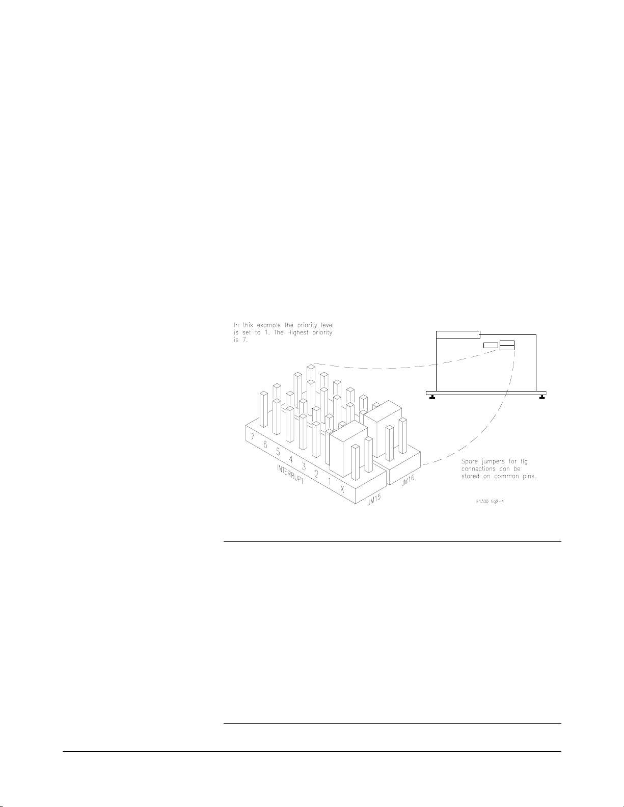
Referring to Figure 2-1, near the P1 connector you w ill find two sets of
jumper pins labeled X and 1 through 7 (JM15 and JM16). The Digital I/O
module is factory-shipped with the interrupt set to 1. If you need to change
the interrupt level you must move both jumpers on the blocks. Spare
jumpers, used for combining the flag (FLG) lines, are stored on the unused
ground pins of this connector when it ships from the factory.
Figure 2-4. Priority Interrupt Connector (Factory Setting)
Note The interrupt circuitry for the HP E1330B is implemented as release on
interrupt acknowledge (ROAK). The HP E1330B Digital I/O module will
de-assert (or release) the interrupt request line during an interrupt
acknowledge cycle.
The interrupt circuitry on the HP E1330A is implemented as release on
register access (RORA). The HP E13 30A Di gital I/O module will continu e
to assert the interrupt request line until the Port Control/Status Register on
the Digital I/O module is accessed.
Both the HP E1330A and HP E1330B may be used with the HP E1300A/
E1301A and with the HP E1405A/B and HP E1406A. If you are using
HP Compiled SCPI (i.e., HP E1570A), you must use the HP E1330B.
20 Configuring the HP E1330B Digital I/O Module Chapter 2
Page 21
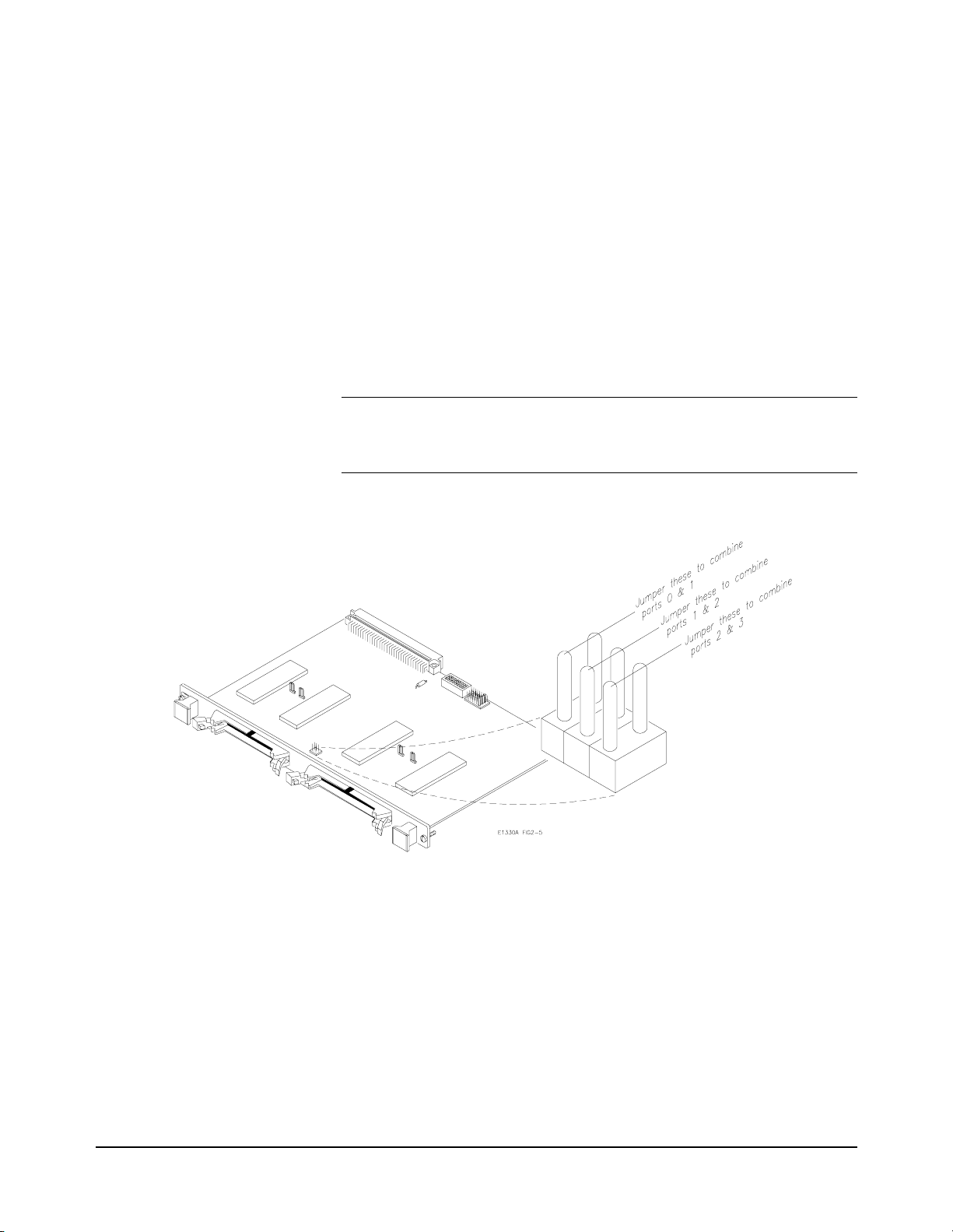
Combining the Flag Lines
Each port contains a Flag Line, labeled FLG, that can be use d to implement
a handshake scheme with a peripheral. For single port operations, the FLG
lines can be used in the factory default setting (no flag lines combined) to
handshake with a peripheral. For multi-port operations with a single
handshake line, you can combine the flag line from multiple ports. The
combined flag lines are physically tied together. An action on any of the
combined flag lines performs that action for all combined flag lines.
Figure 2-5 shows the locations of the flag combining switches and how to
set them. Before setting any flag combine switches, you may wish to read
the discussion regarding allowable port combinations and handshaking in
Chapter 4 of this manual.
Note When using FLG and CTL for handshaking on multiple port operations,
CTL is set for each port sequentially, beginning at the lowest numbered
port.
Figure 2-5. Flag Combine Switches
Configuring the HP E1330B Digital I/O Module 21Chapter 2
Page 22

Digital I/O Module Peripheral Pinout
Figure 2-6 shows pinouts for the Digital I/O module connectors. Each is
compatible with easy cr imp connections to ri bbon cables for standar d digital
I/O interfacing. Figure 2-7 shows the data line location on the supplied
ribbon cables. Figure 2-8 shows ho w to connect th e cables. Deta ils about the
functioning of these pins i s covered in Chapt er 4 — “Understandin g the HP
E1330B Digital I/O Module but line names are as follows:
RES
STS Status Line - used as an auxili ary handshake line. Input
PIR Peripheral Interrupt Line - used to si gnal a peripheral
FLG Flag Line - used to handshake data between a
CTL Control Line - used to handshake data between a
I/O
Reset Line - used to res et a peripheral. Output from the
Digital I/O module.
to the Digital I/ O module.
interrupt. Input to the Digital I/O module.
peripheral and the Digital I/O module. Controlled by
the peripheral. Input to the Dig ital I/O module.
peripheral and the Digital I/O module. Controlled by
the Digital I/O module. Output from the Digital I/O
module.
Input/Output Line - used to establish input or output
on a port. Controlled by the Digital I/O module. Input
to the Digital I/ O module.
22 Configuring the HP E1330B Digital I/O Module Chapter 2
Page 23

Figure 2-6. J1 and J2 Connector Pinouts
Configuring the HP E1330B Digital I/O Module 23Chapter 2
Page 24
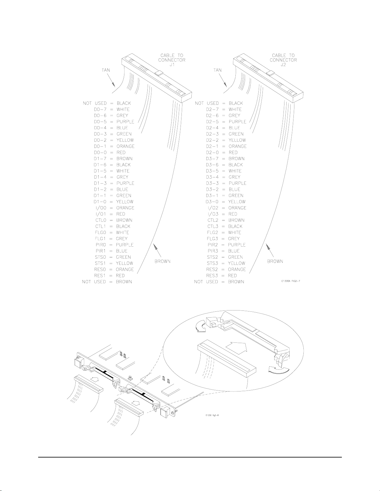
Figure 2-7. Data Line Location on Ribbon Cables
Figure 2-8. Connecting the Digital I/O Cable
24 Configuring the HP E1330B Digital I/O Module Chapter 2
Page 25

Configuring for Isolated Digital I/O
The two Digital I/O module per iph era l connectors, J1 and J2, each ha ve 60
pins. An industry standar d isolated di gital I/O peri pheral, like the Opto 22
16 Position Single Channel Mounting Rack, is a 50-pin connection. The
connector is either a card edge or a header connector (similar to J1 on the
Digital I/O module). For example , the Opto 22
edge connector; PB16H uses a header connector. They both have the same
pin-out for the ribbon ca ble. Both can accommodate up to 16 single chann el
I/O lines.
12 of the wires on the supplied ribbon cable are not connected. Figure 2-8
shows the ribbon cable connect ions. The method of connection to the ribbon
cable can be faci lit ated by the use of sp ecial ty f ixtures for th ese co nnecto rs,
but there is no standard for connector keys or spacing.
For the Opto 22
Pins 27–57 on the ri bbon cable, od d numbered pins on ly, correspo nd to pins
17–47 on the Opto 22
connect pins 1 and 49 on the Opto 22
Procedure 1. Carefully cut lines 1-11 on the ribbon cable and line 59. A tan wire
should be the first wire on the ribbon cable after you make the cut.
rack, lines 1–10 are not used on th e peripher al conne ctor.
rack. All even numbered pins are ground. Do not
rack, PB16C, uses a card
rack connector.
2. Select the 50-pin connector you nee d, either edge connec tor or heade r
connector and attach the ribbon cable.
3. Connect the ribbon cable to the Opto 22
digital operation.
Opto 22 is a registered trademark of Opto 22, Huntington Beach, CA 92649
rack for optically isolated
Configuring the HP E1330B Digital I/O Module 25Chapter 2
Page 26

Connecting to a GPIO Peripheral
The GPIO interface is a widely used standard parallel interface for
connecting computers to peri pherals. The GPIO interface may em ploy up to
32-bits of bi-directional data transfer. The Digital I/O module and the GPIO
interface have identical line definitions but different pin assignments.
Ports A-D on the GPIO are defined as ports 0-3 on the Digital I/O module.
Procedure 1. Connect the ribbon cable to connector J1 and/or J2 on th e Digi ta l I/ O
module.
2. Connect the wires on the ribbon cable to the peripheral as described
in Figure 2-1 for the GPIO interface.
Figure 2-9. Typical Isolated Peripheral Hookup
26 Configuring the HP E1330B Digital I/O Module Chapter 2
Page 27
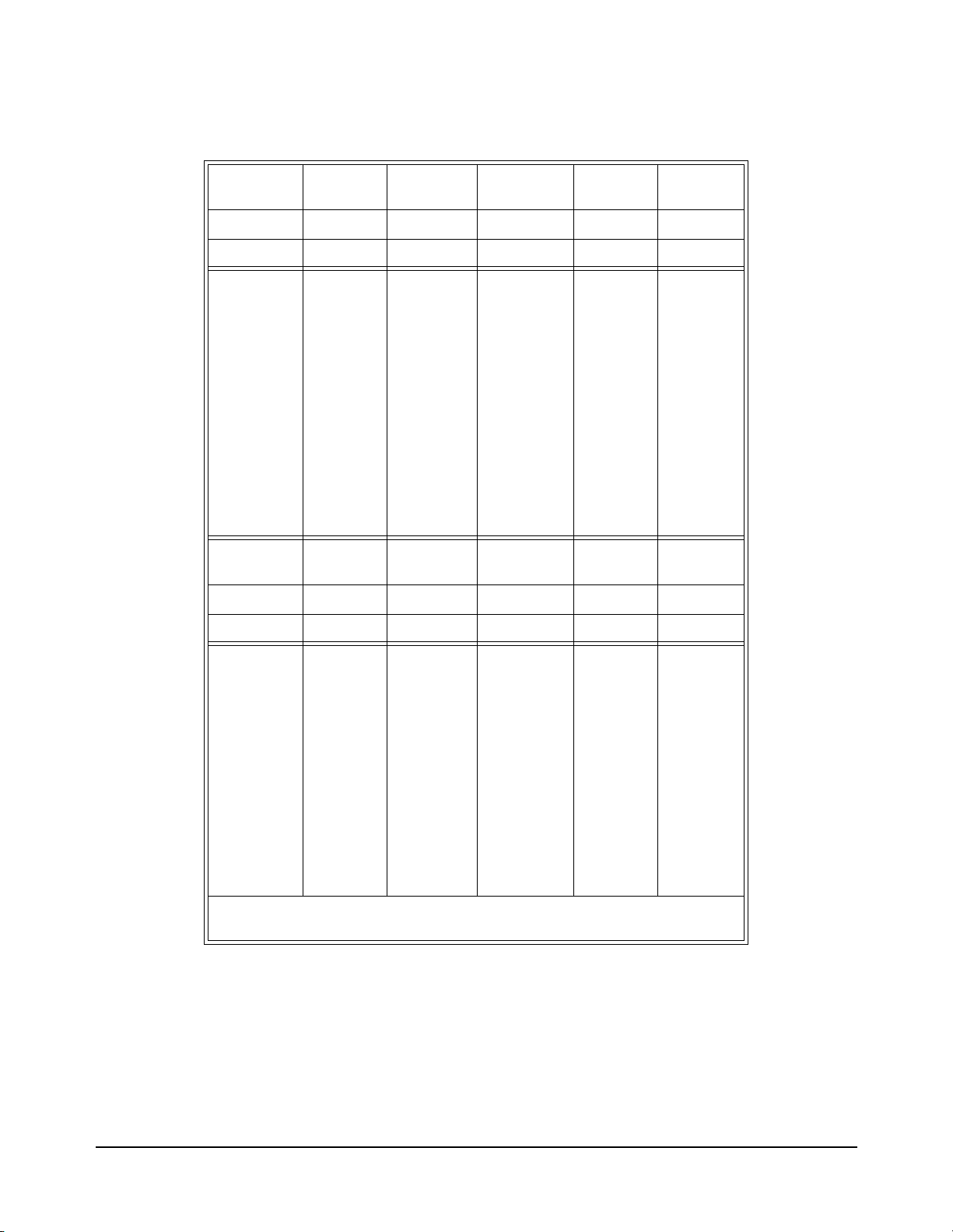
Table 2-1. Digital I/O Pinout to GPIO Pinout
Port 0
Digital I/O GPIO
Connector J1 J2 Connector J1 J2
Name Pin # Pin# Name Pin# Pin#
D00
D01
D02
D03
D04
D05
D06
D07
RES0
STS0
PIR0
FLG0
CTL0
I/O0
Connector J2 J1 Connector J2 J1
43
45
47
49
51
53
55
57
5
9
13
17
21
25
Port 2
Digital I/O GPIO
33
15
34
16
35
17
36
18
12
26
9
27
13
31
D10
D11
D12
D13
D14
D15
D16
D17
RES1
STS1
PIR1
FLG1
CTL1
I/O1
Port 1
Digital I/O GPIO
27
29
31
33
35
37
39
41
3
7
11
15
19
23
Port 3
Digital I/O GPIO
22
21
20
19
29
25
30
11
4
3
2
1
8
7
Name Pin # Pin# Name Pin# Pin#
D20
D21
D22
D23
D24
D25
D26
D27
RES2
STS2
PIR2
FLG2
CTL2
I/O2
For the Digital I/O connectors, all even numbered pins are ground.
For the GPIO connector, pins 5, 6, 10, 14, 23, 24, 28 and 32 are ground.
43
45
47
49
51
53
55
57
13
17
21
25
33
15
34
16
35
17
36
18
5
9
12
26
9
27
13
31
D30
D31
D32
D33
D34
D35
D36
D37
RES3
STS3
PIR3
FLG3
CTL3
I/O3
27
29
31
33
35
37
39
41
11
15
19
23
4
22
3
21
2
20
1
19
3
7
29
8
25
7
30
11
Configuring the HP E1330B Digital I/O Module 27Chapter 2
Page 28

Using with External Pull-ups
The Digital I/O module data lines can be used in an open collector
configuration. Connections for open collector require the use of external
power supplies and pull-up resistors. The internal pull-up mode of the
Digital I/O module shoul d be disabled for open col lector output. Fi gure 2-10
shows a single data line connection. The value of the pull-up resistor is
calculated as follows:
Vcc 5.0 Vdc=
Imax Iout
Vcc
----------- -
R
Imax
The value of TTL high with the 200 Ω pull-up resistor is calculated as
follows:
V
High
Vcc
safety_factor× 48mA 0.52× 25mA===
Low
5
------------ -
0.025
-------------------------- -
× 4.84Vdc==
6200 200+
200Ω== =
6200
Figure 2-10. T ypical Open Collector Data Line
28 Configuring the HP E1330B Digital I/O Module Chapter 2
Page 29

Typica l Connection
Figure 2-11 shows a typical driver/receiver connection for data transfer.
The FLG, PIR, and STS lines have a discrete r esisti ve pull-up network. The
data lines do not have a discrete resistive pull-up, but can use an internal
pull-up in the 75ALS160. The internal pull-up requires that the data lines
sink 3.2 mA to pull the line to less th an 0.4 V. The I/O
are open collector, and require external pull-up to logic high.
, CTL, and RES lines
Figure 2-11. Typical Driver/Receiver Connections
Configuring the HP E1330B Digital I/O Module 29Chapter 2
Page 30

Notes:
30 Configuring the HP E1330B Digital I/O Module Chapter 2
Page 31

Using the HP E1330B Digital I/O Module
Using This Chapter
Chapter 3
This chapter is divi ded into eight sectio ns about transferring dat a to and from
the Digital I/O Module and a peripheral:
• Addressing the Module. . . . . . . . . . . . . . . . . . . . . . . . . . . . . page 31
• Operation Overview . . . . . . . . . . . . . . . . . . . . . . . . . . . . . . . page 32
• Default and Reset States . . . . . . . . . . . . . . . . . . . . . . . . . . . . page 33
• Setting the Polarity . . . . . . . . . . . . . . . . . . . . . . . . . . . . . . . . page 33
• Setting the Handshake Mode . . . . . . . . . . . . . . . . . . . . . . . . page 34
• Inputting Data Bytes and Bits. . . . . . . . . . . . . . . . . . . . . . . . page 35
• Outputting Data Bytes and Bits . . . . . . . . . . . . . . . . . . . . . . page 36
• Multiple Port Operations. . . . . . . . . . . . . . . . . . . . . . . . . . . . page 37
• Using Trace Memory . . . . . . . . . . . . . . . . . . . . . . . . . . . . . . page 38
Addressing the Module
The examples shown in this chapter use the default addresses for the
interface, Command module , and Digital I/O module . The address us es both
HP-IB primary and secondary addresses. The default address is:
Interface Select Code Command module
To establish these defaults as an I/O path in HP BASIC, the program
examples use this code:
10 ASSIGN @Dio TO 70918
Each Digital I/O module in a system must have a different logical address.
Additionally, no two instruments in the same system can have the same
logical address. Setting the logical address is described in Chapter 2 —
“Configuring the HPE1330B Digital I/O Module”.
70 91 8
HP-IB Primary Address HP-IB Secondary
Address
Digital I/O module
HP-IB Address
address
LADDR
------------------- -
8
Using the HP E1330B Digital I/O Module 31Chapter 3
Page 32

Operation Overview
The following steps illustrate general operation of the Digital I/O module.
Figure 3-1. HP E1330B General Operation
32 Using the HP E1330B Digital I/O Module Chapter 3
Page 33

Default and Reset States
At initial power-on and following the *RST command, the Digital I/O
module is set to the following stat es:
CTL line: 0 = TTL Low
I/O
line: TRUE = input = TTL High
Data, FLG, and CTL line Polarity: POSitive
Handshake mode: NONE
Setting the Polarity
The logical true level of the control (CTL) line, the flag (FLG) line, and the
data lines of each port can be set to either TTL high (> 2.5V) or TTL Low
(< 1.4V) levels. SCPI commands use the
[SOURce:]DIGital:CONTroln:POLarity <POSitive or NEGative>
to set the control line’s (CTL) polarity on port n.
[SOURce:]DIGital:FLAGn:POLarity <POSitive or NEGative>
to set the flag line’s (FLG) polarity on port n.
POLarity keyword as:
[SOURce:]DIGital:DATAn:POLarity <POSitive or NEGative>
to set the da ta line’s polarity on port n.
Example 10 ASSIG N @Di o TO 70918
20 DIM Pol$ [3]
30 Pol$ = "POS"
40 OUTPUT @Dio; "DIG:DATA1:POL "&Pol$
50 END
This program sets the polarity to positive on port 1 data lines. A TTL high
will be input as a 1, or a bit set to 1 will output a TTL High level.
*RST (reset) condition is positive polarity for control (CTL), flag
The
(FLG), and data lines on all ports.
Using the HP E1330B Digital I/O Module 33Chapter 3
Page 34

Setting the Handshake Mode
Handshaking ensures corr ect transfer of data between devices. You mus t set
both the mode and the timing to establish correct handshaking. Most
handshake modes use the FLG and CTL lines to control the data transfer.
SCPI commands support the following modes of handshaking:
-- LEADing Edge
-- TRAiling Edge
-- PULSe
-- PAR Tial
-- STRobe
-- NONE
These SCPI commands set the type of handshake mode used:
[SOURce:]DIGital:DATAn[:type]:HANDshake[:MODE] <mode>
[SOURce:]DIGital:HANDshake
n[:MODE] <mode>
Handshake Timing Some handshake modes require that a timing value be set.Primarily, the
timing applies to only output functions (the exception is STRobe Input
handshaking mode). These SCPI commands se t the timing of the hands hake
(where timing applies):
[SOURce:]DIGital:DATAn[:type]:HANDshake:DELay <time>
[SOURce:]DIGital:HANDshakenDELay <time>
Example 10 ASSIG N @Di o TO 70918
20 DIM Hand$ [4]
30 Hand$ = "LEAD"
40 Delay = 0.015
50 OUTPUT @Dio;"DIG:DATA0:BYTE:HAND "&Hand$
60 OUTPUT@Dio;"DIG:DATA0:BYTE:HAND:DEL ";Delay
70 END
Sets the 8-bit por t 0 handshake mode to the LEADing Edge handshak e mode
and sets the output timing handshake delay to 0.015 seconds.
Detailed descripti ons of the ha ndshake modes, t iming diagrams, and the use
of the FLG and CTL lines are given in Chapter 4 —“Understanding the
HP E1330B Digital I/O Module”.
34 Using the HP E1330B Digital I/O Module Chapter 3
Page 35

Inputting Data Bytes and Bits
Data input is performed using commands in the SCPI
MEASure:DIGital:DATAn subsystem. The returned valu e of an input will
depend upon the POLarity programmed for the port.
Both Input and Output operations will attempt to complete the handshake
mode set for the port and may "hang" if required handshake operations are
not completed. To unhang a hung transfer, is sue a IEEE 488 sele cted device
clear. In HP BASIC this is
Input Input operations ca n involve single bits, 8 -bit bytes, or multip le bytes. Single
bit operati ons always return a value of 1 or 0. Byte or multiple byte inp uts
always return values in decimal format.
CLEAR 70918.
Example 10 ASSIGN @Dio TO 70918
20 INTEGER Bits, Bytes, Ready
30 OUTPUT @Dio;"*RST;*OPC?"
40 ENTER @Dio;Ready
50 OUTPUT @Dio;"MEAS:DIG:DATA0:BIT7?"
60 ENTER @Dio;Bits
70 OUTPUT @Dio;"MEAS:DIG:DATA1?"
80 ENTER @Dio;Bytes
90 DISP "Port 0, Bit 7 is "&Bits
100 DISP "Port 1 byte is "&Bytes
110 END
!Establish I/O path to module.
!Reset the module to establish
defaults.
!Wait for completion.
!Input a bit on port 0.
!Input a byte on port 1.
!Show the results.
This example first sets the module to the default state (positive polarity and
no handshake). The state of data line 7 (Bit 7) of port 0 is read. A byte is
input from port 1. The displayed state of the bit input will be either 0 or 1,
depending upon the electric al state of port 0 data line 7. The displ ayed value
of the byte input will range from 0 (all port 1 data lin es lo w) to 255 (all po rt
1 data lines high).
Note Following a *RST command, the port data lines will be configured as
inputs, with the ports terminating resistors pulling them high. Bits will be
read as a 1 and a byte as 255.
Using the HP E1330B Digital I/O Module 35Chapter 3
Page 36

Outputting Data Bytes and Bits
Data output is performed using the commands in SCPI
[SOURce:]DIGital:DATAn subsystem. The TTL levels of an output will
depend upon the POLarity programmed for the port.
Both Input and Output operations will attempt to complete the handshake
mode set for the port and may "hang" if required handshake operations are
not completed. To unhang a hung transfer, is sue a IEEE 488select ed device
clear. In HP BASIC this is
Output Output operations can involve single bits, 8-bit bytes, or multiple bytes.
Single bit output operat ions always expect a value of 0 or 1. Byte or multiple
byte output operations can accept numbers in decimal, hexadecimal, octal,
or binary formats. The choice of output format is indicated by a special
character (#) in the value to be output. If the # character is not used, the
output value is assumed to be in decimal format.
CLEAR 70918.
Example 10 ASSIGN @Dio TO 70918
20 INTEGER Bits, Bytes, Ready
30 Bits= 1
40 Bytes = 255
50 OUTPUT @Dio;"*RST;*OPC?"
60 ENTER @Dio;Ready
70 OUTPUT@Dio;"DIG:DATA0:BIT5 "&VAL$(Bits)&";*OPC?"
80 ENTER @Dio;Ready
90 OUTPUT@Dio;"DIG:DATA1 "&VAL$(Bytes)&";*OPC?"
100 ENTER @Dio;Ready
110 END
This example sets bit 5 on port 0 to a logical true value (with the default
polarity establi shed, th e data li ne is set to TTL high). The example th en sets
all the data lines on por t 1 to TTL high. Port 0, bit 5 and port 1 data lines will
remain in the TTL high condition until another output command or input
command at the same port is received.
!Establish I/O path to module.
!Reset the module to establish
defaults.
!Wait for completion.
!Set port 0 bit 5 true.
!Wait for completion.
!Output a byte on port 1.
!Wait for completion.
36 Using the HP E1330B Digital I/O Module Chapter 3
Page 37

Multiple Port Operations
The Digital I/O module supports multiple port operations using a single
SCPI command. Multiple port operations are shown in the SCPI command
syntax as the optional keyword
syntax initiates a handshake and returns a value:
MEAS:DIG:DATAn[:type]?
The optional keyword [:type] is re placed by one of the foll owing keywords :
[:type]. For example, this SCPI command
:BYTE
This keyword, or no keyword (default), is used for 8-bit port
operations.
:WORD This ke yword is used to combine 2 adjace nt ports for 16-bit port
:LWORd
operations.
This keyword is used to combine all 4 ports for 32-bit operations.
Example 10 ASSIGN @Dio TO 70918
20 DIM Pat_1$[8], Pat_2$[8], Hand$[4]
30 Pat_1$="AAAAAAAA"
40 Pat_2$ = "55555555"
50 Hand$ = "LEAD"
60 OUTPUT @Dio;"*RST;*OPC?"
70 ENTER @Dio;Ready
80 OUTPUT@Dio;"DIG:DATA0:LWORD:HAND "&Hand$&";*OPC?"
90 ENTER @Dio;Ready
100 OUTPUT@Dio;"DIG:DATA0:LWORD:HAND:DEL .015;*OPC?"
110 ENTER @Dio;Ready
120 OUTPUT@Dio;"DIG:DATA0:LWORD #H"&Pat_1$&";*OPC?"
130 ENTER @Dio;Ready
140 OUTPUT@Dio;"DIG:DATA0:LWORD #H"&Pat_2$&";*OPC?"
150 ENTER @Dio;Ready
160 END
!Establish I/O path to module.
!Alternating 1 and 0.
!Alternating 0 and 1.
!Reset the module to establish
defaults.
!Wait for completion.
!Set LEADing handsh ake for 32
bit operations.
!Wait for completion.
!Set handshake delay time.
!Wait for completion.
!Set 32 bits, use handshake,
alternating 1 and 0.
!Wait for completion.
!Set 32 bits, use handshake,
alternating 0 and 1.
!Wait for completion.
This example combines all four ports for handshaking and output
operations. The handshake mode is set to LEADing. The output data is given
in hexadecimal as specifi ed by the
#H characters. When using mult iple port
handshaking, use the highest numbered port CTL line to ensure a correct
handshake.
Using the HP E1330B Digital I/O Module 37Chapter 3
Page 38

Using Trace Memory
Trace memory can speed input and output operations and free your system
controller during multiple byte input or output operations. A portion of
system memory is set aside and data is read or written as blocks. Trace
memory allows the fastest operation of the Digital I/O module. The rate of
transfer of each block of data is determined by the handshake speed of the
Digital I/O module and the peripheral.
Note Byte swapping may occur when using the :TRACe commands. If you are
using a Motorola processor, the bytes are written or read to memory with
the lowest port receiving the least significant byte (the case when directly
addressing the po rt through SCPI commands) . An Intel processo r , ho wever ,
when used with the
bytes. The bytes are written or read from memory with the lowest port
receiving the most si gnificant byte and the highest port the l east significant
byte.
Trace Memory Example 1 This example writes 20 bytes as 10 WORDS at ports 0 and 1.
10 RE-SAVE "Trace_1"
20 ASSIGN @ Dio TO 70918
30 INTEGER A(1:10) , Ready
40 DATA 65,66,67,68,69,70,71,72 ,73, 74
50 READ A(*)
60 OUTPUT @Dio;"*RST;*OPC?"
70 ENTER @Dio;Ready
80 OUTPUT@Dio;"SOUR:DIG:TRAC :DEF alpha,100;*OPC?"
90 ENTER @Dio;Ready
100
OUTPUT @Dio USING"K,10(W)";"SOUR:DIG:TRAC alpha,#220";A(*)
110 OUTPUT@Dio;"SOUR:DIG:DATA0:WORD:TRAC alpha;*OPC?"
120 ENTER @Dio;Ready
130 OUTPUT @Dio;"SOUR:DIG:TRAC:DEL alpha;*OPC?"
140 ENTER @Dio;Ready
150 END
:TRACe commands will swap the order the of the
!A, B, C, D, E, F, G, H, I, J.
!Wait for completion.
!Define memory name alpha.
!Wait for completion.
!Fill memory alpha with 20
bytes.
!Output the 20 bytes.
!Wait for completion.
!Delete memory alpha.
!Wait for completion.
38 Using the HP E1330B Digital I/O Module Chapter 3
Page 39

Trace Memory Example 2 This example writes 20 bytes as 10 WORDS at ports 0 and 1 as in the first
example, it uses an external VME memory board.
10 RE-SAVE "Trace_2"
20 ASSIGN @ Dio TO 70918
30 INTEGER A(1:10) , Ready
40 DATA 65,66,67,68,69,70,71,72 ,73, 74
50 READ A(*)
60 OUTPUT @Dio;"*RST;*OPC?"
70 ENTER @Dio;Ready
80 OUTPUT @Dio;"MEM:VME:ADDR #H200000"
90 OUTPUT @Dio;"MEM:VME:SIZE 100"
100 OUTPUT @Dio;"MEM:VME:STAT ON"
110 OUTPUT@Dio;"SOUR:DIG:TRAC:DEF alpha,100;*OPC?"
120 ENTER @Dio;Ready
130
OUTPUT @Dio USING"K,10(W)";"SOUR:DIG:TRAC alpha,#220";A(*)
140 OUTPUT@Dio;"SOUR:DIG:DATA0:WORD:TRAC alpha;*OPC?"
150 ENTER @Dio;Ready
160 OUTPUT@DIO;"SOUR:DIG:TRAC:DEL alpha,*OPC?"
170 ENTER @Dio;Ready
180 END
!A, B, C, D, E, F, G, H, I, J.
!Wait for completion.
!Define memory location.
!Reserve 100 bytes.
!Enable memory.
!Define memory name alpha.
!Wait for completion.
!Fill memory alpha with 20
bytes.
!Output the 20 bytes.
!Wait for completion.
!Delete memory alpha.
!Wait for completion.
Trace Memory Example 3 This example reads 40 WORDS from ports 0 and 1.
10 RE-SAVE "Trace_3"
20 ASSIGN @ Dio TO 70918
30 DIM Head$[4]
40 INTEGER A(1:20) , Ready
50 OUTPUT @Dio;"*RST;*OPC?"
60 ENTER @Dio;Ready
70 OUTPUT@Dio;"SOUR:DIG:TRAC :DEF alpha,80;*OPC?"
80 ENTER @Dio;Ready
90 OUTPUT@Dio;"MEAS:DIG:DATA0:WORD:TRAC alpha;*OPC?"
100 ENTER @Dio;Ready
110 OUTPUT @Dio;"SOUR:DIG:TRAC:DATA ? alpha"
120 ENTER @Dio USING "4A,40(W)";Head$;A(*)
130 OUTPUT @Dio;"SOUR:DIG:TRAC:DEL alpha;*OPC?"
140 ENTER@Dio;Ready
150 END
!Wait for completion.
!Define memory name alpha.
!Wait for completion.
!Output 80 bytes.
!Wait for completion.
!Request the data.
!Remove memory block.
!Wait for completion.
Using the HP E1330B Digital I/O Module 39Chapter 3
Page 40

Notes:
40 Using the HP E1330B Digital I/O Module Chapter 3
Page 41

Chapter 4
Underst anding the HP E1330B Digital I/O
Module
Using This Chapter
This chapter provides explanations of the signal lines, handshake modes,
and port combining for the Digital I/O Module. This chapter has the
following topics.
• Port Description . . . . . . . . . . . . . . . . . . . . . . . . . . . . . . . . . . page 41
• Default and Reset States . . . . . . . . . . . . . . . . . . . . . . . . . . . . page 43
• Setting the Polarity . . . . . . . . . . . . . . . . . . . . . . . . . . . . . . . . page 43
• Using the Handshake Modes. . . . . . . . . . . . . . . . . . . . . . . . . page 44
• Inputting Data Bytes and Bits. . . . . . . . . . . . . . . . . . . . . . . . page 50
• Outputting Data Bytes and Bits . . . . . . . . . . . . . . . . . . . . . . page 51
• Multiple Port Operations. . . . . . . . . . . . . . . . . . . . . . . . . . . . page 53
Port Description
Data Lines Each port has 8 data lines, numbered from 0 to 7. The data lines can be set
Each of the Digital I/O modul e ports has 8 data lines and 6 control lines . Not
all these lines are required for every application. A simplified diagram of a
port is shown in Figure 1- 1 on page 11. The fo llowin g subsect ions des cribe
the use of these lines.
as an 8-bit group, as part of a larger group, or individually using SCPI
commands.
The logical TRUE condition of the data lines can be controlled with SCPI
commands. Positive polarity is the default. The following table shows the
effect of changing the polarity with Input and Output operations for each
data line.
Input Operations Output Operations
TTL High = 1 1 = TTL High
POSitive Polarity
NEGative Polarity
TTL Low = 0 0 = TTL Low
TTL High = 0 0 = TTL High
TTL Low = 1 1 = TTL Low
Understanding the HP E1330B Digital I/O Module 41Chapter 4
Page 42

The FLG Line (Input) Each port has a flag ( FLG) line. A flag li ne is an input line from a pe ripheral
and has two states: READY and BUSY. A flag line is normally used in
conjunction with the corresponding control line (CTL) to establish a
handshake between a peripheral and the Digital I/O Module. SCPI
commands that define handshake modes typically use the FLG and CTL
lines. The state of the FLG line can also be read with a SCPI command to
implement custom handshakes. Positive polarity is the default. The
following shows the effect of changing the polarity of the FLG line.
POSitive Polarity TTL High = BUSY = 1
TTL Low = READY = 0
NEGative Polarity TTL High = READY = 0
TTL Low = BUSY = 1
The CTL Line
(Output)
Each port has a control line (CTL). A control line is an open collector output
line from the Digital I /O module to the perip heral and has two states: TRUE
and FALSE. A control line is normally used in conjunction with the
corresponding flag lin e on the same port to establi sh a handshake betw een a
peripheral and the Digital I/O Module. SCPI commands that define
handshake modes typicall y use the FLG and CTL lines. Th e state of the CTL
line can be read and set with SCPI commands to implement custom
handshakes. Positive polar ity is the default. The fo llowing shows the effect
of changing the polarity of the CTL line.
POSitive Polarity TTL High = TRUE = ON = 1
TTL Low = FALSE = OFF = 0
NEGative Polarity TTL High = FALSE = OFF = 0
TTL Low = TRUE = ON = 1
The I/O Line (Output) Each port has an open collector I/ O line which is output fr om the Digita l I/O
module to the peripher al and has two states: TRUE or FALSE. The state of
the I/O
The data transceiver of that port is enabled for input. The peripheral may
respond to the signal by enabling itself to send data.
line is not directly programmable.
When the I/O
line is: TTL High = TRUE = 1 = Input
When the I/O line is: TTL Low = FALSE = 0 = Output
The data transceiver of that port is enabl ed for output. The per ipheral should
respond to the signal by enabling itself to receive data.
Caution To prevent damage to the Digit al I/O module, when the I/O line is
set for Output (TTL Low), the peripheral MUST NOT attempt to
source on any data lines.
42 Understanding the HP E1330B Digital I/O Chapter 4
Page 43

The STS Line Each port has a status line labeled STS. The STS line is an input line to the
Digital I/O module. The use of the STS line is only at the register leve l, and
is not supported by SCPI commands. Refer to Appendix B for more
information about this line.
The PIR Line Each port has a peripheral interrupt request line l abeled PIR. The PI R line is
an input line to th e Digital I/O module. The use of t he PIR li ne is only at the
register level, and is not supported by SCPI commands. Refer to Appendix
B for more information about this line.
The RES Line Each port has a reset line labeled RES. The RES line is an open collector
output line to the peripheral. Control of the RES
level and is not supported by SCPI commands. Refer to Appendix B for
more information about this line .
Default and Reset States
At initial power-on and following the *RST command, the Digital I/O
module is set to the following stat es:
CTL line: 0 = TTL Low
line is only at the register
Setting the Polarity
Example DIG:DATA1:POL POS
line: TRUE = input = TTL High
I/O
Data, FLG, and CTL line Polarity: POSitive
Handshake mode: NONE
The logical true level of the control (CTL) line, the flag (FLG) line, and the
data lines of each port can be set to either TTL high (>2.5V) or TTL Low
(<1.4V) levels. SCPI commands use the POLarity keyword as:
[SOURce:]DIGital:CONTroln:POLarity <POSitive or NEGative>
to set the control line’s (CTL) polarity on port n.
[SOURce:]DIGital:FLAGn:POLarity <POSitive or NEGative>
to set the flag line’s (FLG) polarity on port n.
[SOURce:]DIGital:DATAn:POLarity <POSitive or NEGative>
to set the da ta lines polarity on port n.
Sets the polarity to posit ive o n port 1 dat a line s, a TTL high wi ll be input as
a 1, or a bit set to 1 will output a TTL High level.
*RST (reset) condition is positive polarity for control (CTL),
The
flag (FLG), and data lines on all ports.
Understanding the HP E1330B Digital I/O Module 43Chapter 4
Page 44

Using the Handshake Modes
Handshaking ensures corr ect transfer of data between devices. You mus t set
both the mode and the timing to establish correct handshaking. SCPI
commands support the following modes of handshaking:
-- LEADing Edge
-- TRAiling Edge
-- PULSe
-- PARTial
-- STRobe
-- NONE
These SCPI commands set the type of handshake mode used:
[SOURce:]DIGital:DATAn[:type]:HANDshake[:MODE] <mode>
[SOURce:]DIGital:HANDshake
These SCPI commands set the timing of the handshake (where timing
applies):
[SOURce:]DIGital:DATAn[:type]:HANDshake:DELay <time>
[SOURce:]DIGital:HANDshake
n[:MODE] <mode>
n:DELay <time>
44 Understanding the HP E1330B Digital I/O Chapter 4
Page 45

Handshake Modes The operation of each handshake mode for input or output operations is
described in the following subsections. In these discussions, only the FLG,
CTL, and DATA lines a re included. Ot her port control lines, contr olled only
through register access, are described in Appendix B of this manual.
LEADing Edge The LEADing Edge handshake makes use of both the CTL and FLG lines.
The input and output operations are described below.
INPUT OUTPUT
1 The Digital I/O module sen ses the
FLG line and waits for READY.
2 The Digital I/O module sets the
I/O line HIGH.
3 The Digital I/O module sets CTL
TRUE.
4 The peripheral senses the CTL
line and places data on the dat a
lines.
5 The peripheral sets the FLG line
to BUSY indicating data is valid.
6 The Digital I/O module sen ses the
FLG line and latches the data.
7 The Digital I/O module returns
CTL to FALSE.
8 The peripheral senses the CTL
line and returns the FLG line to
READY.
1 The Digital I/O mo dule ch ecks the
state of the FLG line (must be
READY).
2 The Digital I/O module sets the
I/O line LOW.
3 The Digital I/O module places the
data on the data lines.
4 After waiting the progr ammed
delay time, Td, the Digital I/O
module sets CTL to TRUE.
5 The peripheral senses the CTL
line and sets the FLG line to
BUSY while it latches the data.
6 When the Digital I/O module
senses the FLG line in the BUSY
state, it sets the CTL line to
FALSE and monitors the FLG line.
7 When the peripheral returns the
FLG line to READY (indicating it
has latched the data) the next
handshake can begin.
Understanding the HP E1330B Digital I/O Module 45Chapter 4
Page 46

TRAiling Edge The TRAiling Edge handshake makes use of both the CTL and FLG lines.
The input and output operations are described below.
INPUT OUTPUT
1 The Digital I/O module sen ses the
FLG line and waits for READY.
2 The Digital I/O module sets the
line HIGH.
I/O
3 The Digital I/O module sets CTL
TRUE.
4 The peripheral senses the CTL
line and sets the FLG line to
BUSY.
5 The Digital I/O module sen ses the
FLG BUSY and sets the CTL line
FALSE.
6 The peripheral senses the CTL
line change and places data on
the data lines.
7 The peripheral indicates the data
is valid by returning the FLG line
to READY.
8 The Digital I/O module sen ses the
FLG READY and latc hes th e data.
1 The Digital I/O mo dule ch ecks the
state of the FLG line (must be
READY).
2 The Digital I/O module sets the
I/O line LOW.
3 The Digital I/O module places the
data on the data lines.
4 After waiting the progr ammed
delay time, Td, the Digital I/O
module sets CTL to TRUE.
5 The peripheral senses the CTL
line and sets the FLG line to
BUSY while it latches the data.
6 The peripheral returns the FLG
line to READY indicating the end
of data transfer.
7 The Digital I/O modul e senses th e
FLG line in the READY state and
returns CTL to FALSE.
46 Understanding the HP E1330B Digital I/O Chapter 4
Page 47

PULSe The PULSe handshake makes use of both the CTL an d FLG lines. The input
and output operations are described below.
INPUT OUTPUT
1 The Digital I/O module sen ses the
FLG line and waits for READY.
2 The Digital I/O module sets the
line HIGH.
I/O
3 The Digital I/O module sets CTL
TRUE.
4 The peripheral senses the CTL
line and sets the FLG line to
BUSY.
5 The peripheral places the dat a on
the data lines and indicates valid
data by setting the FLG line to
READY.
6 The Digital I/O module sen ses the
FLG READY, returns CTL to
FALSE, and latches the input
data.
1 The Digital I/O mo dule ch ecks the
state of the FLG line (must be
READY).
2 The Digital I/O module sets the
I/O line LOW.
3 The Digital I/O module places the
data on the data lines.
4 After waiting the progr ammed
delay time, Td, the Digital I/O
module sets CTL to TRUE.
5 The Digital I/O module then waits
another delay time, Td, and sets
the CTL line to FALSE.
6 The peripheral senses the CTL
line change, sets the FLG line to
BUSY and latches the data.
7 When the data is entered, the
peripheral returns the FLG line to
READY.
Understanding the HP E1330B Digital I/O Module 47Chapter 4
Page 48

PARTial The PARTial handshake makes use of both the CTL and FLG lines. The
input and output operations are described below.
INPUT OUTPUT
1 The Digital I/O module sets the
line HIGH.
I/O
2 The Digital I/O module sets CTL
TRUE.
3 The peripheral senses the CTL
line and sets the data lines.
4 The peripheral holds the FLG
line READY for at least
250 nsecs and the n set s the FL G
line BUSY to indicate the data is
valid.
5 The Digital I/O module sen s es
the FLG line change to BUSY
and latches the data.
6 The Digital I/O module then sets
the CTL line FALSE.
1 The Digital I/O module sets the
I/O line LOW.
2 The Digital I /O module places the
data on the data lines.
3 After waiting the programmed
delay time, Td, the Digital I/O
module sets CTL to TRUE.
4 The peripheral senses the CTL
line change, sets the FLG line to
READY for a minimum of
250 nsecs, latches the data, and
sets the FLG line to BUSY.
5 The Digital I/O module senses
the change of the FLG line and
sets CTL to FALSE.
48 Understanding the HP E1330B Digital I/O Chapter 4
Page 49
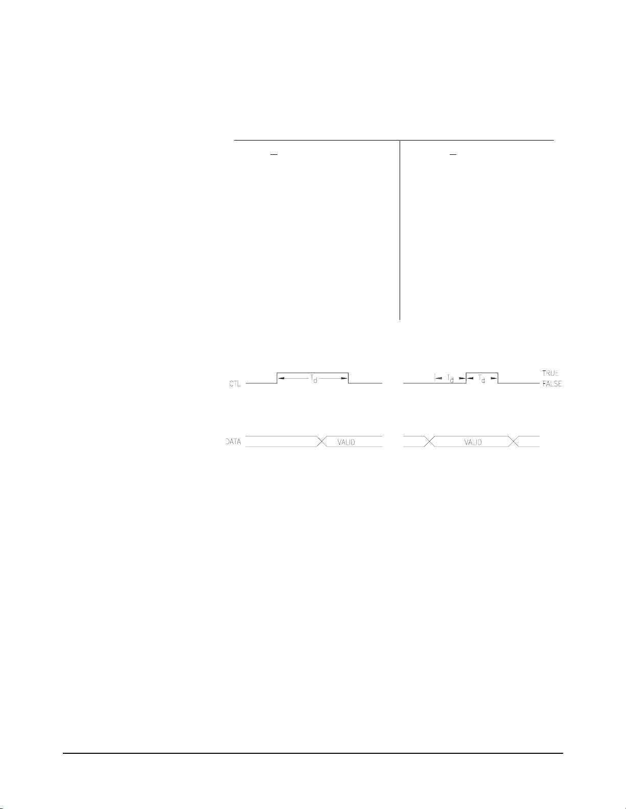
STRobe The STRobe handshake makes use t he CTL l ine, but not the FLG line. The
input and output operations are described below.
INPUT OUTPUT
1 The Digital I/O module sets the
2 The Digital I/O m odule sets CTL
3 The peripheral senses the CTL
4 The Digita l I/O mod ule wa its the
5 The Digital I/O module then
line HIGH.
I/O
TRUE.
line and sets the data lines.
programmed time delay, Td,
after setting CTL TRUE and then
latches the data.
returns CTL to FALSE.
1 The Digital I/O module sets
the I/O line LOW.
2 The Digita l I/O module pl aces
the data on the data lines.
3 After waiting the programmed
delay time, Td, the Digital I/O
module sets CTL to TRUE.
4 The peripheral senses the
CTL line and latches the data.
5 After waiting the programmed
delay time, Td, the Digital I/O
module sets CTL to FALSE.
NONE When handshake is set to NONE, no control or flag lines are used. The
Digital I/O module will inpu t data or output data when programmed. The I /O
line is set for output (LOW) before data is output. Data lines programmed
for output will remain as output until another command is received.
Handshake NONE can be combined with the SCPI commands
MEASure:DIGital:FLAGn and [SOURce:]DIGital:CONTroln to create
custom handshakes.
Handshake Timing Handshake timing is set through the SCPI commands
[SOURce:]DIGital:DATAn[:type]:HANDshake:DELay <time> or
[SOURce:]DIGital:HANDshakenDELay <time
generally used for data output operations. Timing for data input affects only
STRobe handshake modes.
Understanding the HP E1330B Digital I/O Module 49Chapter 4
>
. Handshake timing is
Page 50

Inputting Data Bytes and Bits
Data input is performed using commands in the SCPI
MEASure:DIGital:DATAn subsystem. The returned valu e of an input will
depend upon the POLarity programmed for the port.
Input operations ca n involve single bits, 8 -bit bytes, or multip le bytes. Single
bit input operations always return a decimal value of
byte input operations always return numbers in decimal format.
Both Input and Output operations will attempt to complete the handshake
mode set for the port and may "hang" if required handshake operations are
not completed. To unha ng a hun g tran sfer iss ue a I EEE 488 sel ecte d devic e
clear. In HP BASIC this is
Bit Input The SCPI command for inputting the state of a single bit on a data port is:
MEASure:DIGital:DATAn[:type]:BITm
0 or 1. Byte or multiple
CLEAR 70918.
This command instruc ts the Digi tal I/O modul e to retur n a val ue of eith er
1, indicating the condition of b it m on port n, following comple tion of the
or
input handshake. The value returned depe nds upon the prog rammed state of
the port POLarity. I n the def ault st ate (POSit ive pola rity) a TTL high on the
data line specified by m will return a
HP BASIC program code will request and display the state of data line 3
(bit-3) on po rt 4.
120 OUTPUT @Dio;"MEAS:DIG:DATA4:BIT3?"
130 ENTER @Dio;Bits
140 DISP "State of bit 3 on port 4" &Bits
Bit numbers range from 0 to 7 for single port operations. For multiple port
operations, bit numbers can range from 0 to 31. The section “Multiple Port
Operations” beginning on page 53 describes bi t numbering for multipl e port
operations. For a single port, the data line numbers and bit numbers
correspond:
Dn-7 Dn-6 Dn-5 Dn-4 Dn-3 Dn-2 Dn-1 Dn-0
Bit 7 Bit 6 Bit 5 Bit 4 Bit 3 Bit 2 Bit 1 Bit 0
In this manual the p hysical dat a lines are indicated as Dn-1. The n should be
replaced with the por t number f or th e in put oper ation . For exa mple, bi t 3 of
port 2 affects the state of data line D2-3.
1. For example, the following
0
Byte Input The SCPI command requesting an 8-bit byte from a data port is:
MEASure:DIGital:DATAn[:BYTE][:VALue]?
This command instructs the Digital I/O module to return a decimal value
between 0 and 255, indicating the condition of the data lines on port n,
following completion of the input handshake. The value returned depends
upon the programmed state of the port POLarity. In the default state
50 Understanding the HP E1330B Digital I/O Chapter 4
Page 51

(POSitive polarity) if all data lines are at a TTL low level , the returned val ue
will be
0; if all lines are at a TTL hig h level, the retur ned value will be 255.
For example, the following HP BASIC program code will request and
display the decimal value of the data lines on port 2.
120 OUTPUT @Dio;"MEAS:DIG:DATA2?"
130 ENTER @Dio;Result
140 DISP "Decimal value of port 2 data lines ";Result
Port numbers range from 0 to 3 for single port operations. The section
“Multiple Port Operations” begi nning on page 53 describes port nu mbering
for multiple port operations. For a single port, the returned decimal value
will have the following correspondence to the port data lines:
Dn-7 Dn-6 Dn-5 Dn-4 Dn-3 Dn-2 Dn-1 Dn-0
Bit 7 Bit 6 Bit 5 Bit 4 Bit 3 Bit 2 Bit 1 Bit 0
MSB LSB
Outputting Data Bytes and Bits
Data output is performed using the commands in SCPI
[SOURce:]DIGital:DATAn subsystem. The TTL levels of an output will
depend upon the POLarity programmed for the port.
Output operations can involve single bits, 8-bit bytes, or multiple bytes.
Single bit output operations always expect a value of
0 or 1. Byte or
multiple byte output operations can accept numbers in decimal,
hexadecimal, octal, or binary formats.
Both Input and Output operations will attempt to complete the handshake
mode set for the port and may "hang" if required handshake operations are
not completed. To unha ng a hun g tran sfer iss ue a I EEE 488 sel ecte d devic e
clear. In HP BASIC this is
CLEAR 70918.
Bit Output The SCPI command for setting the state of a single bit on a data port is:
[SOURce:]DIGital:DATAn[:type]:BITm <value>
This command instructs the Digital I/O module to set bit m on port n to
<value
>
, using the output handshake. The actual TTL level set on the
corresponding data line depends upon the programmed state of the port
polarity. If
<value
the data line corresponding to bit m will be set to a TTL high level. For
example, the following HP BASIC program code will set the state of data
line 2 (bit-2) on port 3 to a value of 1.
120 OUTPUT @Dio;"DIG:DATA3:BIT2 1"
Bit numbers range from 0 to 7 for single port operations. For multiple port
operations, bit numbers can range from 0 to 31. The section “Multiple Port
Operations” beginning on page 53 describes bi t numbering for multipl e port
>
is 1 and the default pol arit y (POSit ive po lari ty) is used,
Understanding the HP E1330B Digital I/O Module 51Chapter 4
Page 52

operations. For a single port, the data lines number and bit numbers are:
Dn-7 Dn-6 Dn-5 Dn-4 Dn-3 Dn-2 Dn-1 Dn-0
Bit 7 Bit 6 Bit 5 Bit 4 Bit 3 Bit 2 Bit 1 Bit 0
In this manual the p hysical dat a lines are indicated as Dn-1. The n should be
replaced with the por t number f or th e in put oper ation . For exa mple, bi t 3 of
port 2 affects the state of data line D2-3.
Byte Output The SCPI command syntax to send an 8-bit byte to a data port is:
[SOURce:]DIGital:DATAn[:BYTE][:VALue] [<base>]<value>
This command instr ucts the Digi tal I/O module to se t the port n data lines to
<value
>
using the output hands hake. The optional parame ter <base> defines
the numbering system to use to impl ement
<base
>
are four values allowed for
no parameter decimal format
#H hexadecimal format
#Q octal format
:
<value
>
on the data lines. There
#B binary format
The TTL levels set on the data lines depends upon the programmed port
polarity. In t he de fault sta te ( POSiti ve pol arit y) a TTL high l evel will be s et
for any bit set to 1. For example, the following four HP BASIC program
lines all perform the same function and set the same data lines on port 3:
120 OUTPUT @Dio;"DIG:DATA3 170"
120 OUTPUT @Dio;"DIG:DATA3 #HAA"
120 OUTPUT @Dio;"DIG:DATA3 #Q252"
120 OUTPUT @Dio;"DIG:DATA3 #B10101010"
If port 3 is in the default POSitive polarity mode, the TTL levels set on the
data lines by any of the program lines above will be:
TTL level High Low High Low High Low High Low
Data line D3-7 D3-6 D3-5 D3-4 D3-3 D3-2 D3-1 D3-0
Port numbers range from 0 to 3 for single port operations. The section
“Multiple Port Operations” begi nning on page 53 describes port nu mbering
and byte order for multiple port operations. For single port operations, the
most significant bit is bit 7. The table below sh ows the bit numbers and data
lines.
n-7 Dn-6 Dn-5 Dn-4 Dn-3 Dn-2 Dn-1 Dn-0
D
Bit 7 Bit 6 Bit 5 Bit 4 Bit 3 Bit 2 Bit 1 Bit 0
MSB LSB
52 Understanding the HP E1330B Digital I/O Chapter 4
Page 53

Multiple Port Operations
The Digital I/O module suppo rts multiple port ope rations. You can combi ne
operations using 2 or 4 ports with a single SCPI command. Multiple port
operations are shown in th e SCPI command sy ntax as the op tional key word
[:type]. For example, this SCPI command syntax initiates a handshake and
returns a valu e:
MEAS:DIG:DATAn[:type]?
The optional keyword [:type] is re placed by one of the foll owing keywords :
:BYTE
This keyword, or no keyword (default), is used for 8-bit port
operations.
:WORD
This keyword is used to combine 2 adjacent port s for 16-bit port
operations.
:LWORd
The SCPI keyword
This keyword is used to combine all 4 ports for 32-bit operations.
:DATAn specifies the port to be used for operations by
replacing n with the port number. Mu ltiple port operatio ns have fixed values
allowed for n. For all operations, if n is omitted, port 0 is assumed. The
values allowed for n are:
Operation
:BYTE 0, 1, 2, or 3
:WORD 0 or 2
:LWORd 0
Values of n
For example, the foll owi ng HP BASIC pr ogr am c ode wil l obt ai n a decimal
value of the state of the 32 data lines contained in physical por ts 0, 1, 2 and 3.
120 OUTPUT @Dio;"MEAS:DIG:DATA0:LWORD?"
130 ENTER @Dio;Result
140 DISP "32 bit longword at port 4 ";Result
Multiple Port
Handshaking
The SCPI command syntax to establish a multiple port handshake and set
handshake timing is:
[SOURce:]DIGital:DATAn[:type]:HANDshake[:MODE] <mode>
[SOURce:]DIGital:DATA
n[:type]:HANDshake:DELay <time>
The optional keyword [:type], parameter DATAn, handshake <mode>, and
<time
>
handshake delay
, are all described earlier in th is chapter. See the
sections “Handshak e Modes”, “Handshake Ti ming”, and the intr oduction to
“Multiple Port Operations” for explanations of these keywords and
parameters.
Understanding the HP E1330B Digital I/O Module 53Chapter 4
Page 54

Multiple port handshaking has the following two abnormalities regarding
the CTL and FLG control lines:
•Input or Output handshaking using the CTL line. The CTL line is
set TRUE or FALSE sequentially on all ports involved in the
operation, from the lowest numbered port to the highest numbered
port. A slight time de la y exists between each po rt se tt ing the CTL line
TRUE or FALSE. When using handshaking on multiple port
operations, use the highest numbered port CTL line to ensure correct
data transfer.
•Input or Output handshaking using the FLG line. A change in the
state of any FLG line on any combined port continues the handshake
operation for all the c ombined ports . FLG lines can also be electric ally
combined through a jumper setting (see Chapter 2).
Multiple Port
Input/Output
Data input is performed using commands in the SCPI
MEASure:DIGital:DATAn subsystem. Data output is performed using the
commands in SCPI
[SOURce:]DIGital:DATAn subsystem.
The returned value of an input, or the TTL levels of an output, will depend
upon the POLarity programmed.
Both Input and Output operations will attempt to complete the handshake
mode set and may "hang" if required handshake operations are not
completed.
The sections “Byte Input” and “Byte Output”, earlier in this chapter,
describe operations that also apply to multiple port commands. The values
used for input and output operations depend upon the
[:type] used in the
command. Values for multiple port output operations are given below.
Input Operations Output Operations
Format Range Format Range
BYTE Decimal 0 to 255 Decimal
#H
#Q
#B
WORD Decimal -32768
to
32767
Decimal
#H
#Q
#B
-128 to 255
00 to FF
000 to 377
8-bits
-32768 to 32767
0000 to FFFF
00000 to 177777
16-bits
LWORd Decimal -2147483648
to
2147483647
Table 4-1 shows allowable port combinations for each value of
Decimal
#H
#Q
#B
-2147483648 to 2147483647
00000000 to FFFFFFFF
0 to 37777777777
32-bits
[:type].
You can combine multi pl e po rt ope rations on the same Di git al I /O mod ule .
For example, you could define two independent 16-bit ports at port 0 and
port 2.
54 Understanding the HP E1330B Digital I/O Chapter 4
Page 55

Table 4-1. Port Combinations for [:type] Values
8-bit (BYTE) operations
Port # 0123
Bit Designations 7–0 7–0 7–0 7–0
Data Lines D0_7–D0_0 D1_7–D1_0 D2_7–D_0 D3_7–D3_0
Parameters <
Port # 02
Bit Designations 15–8 7–0 15–8 7–0
Data Lines D0_7–D0_0 D1_7–D1_0 D2_7–D_0 D3_7–D3_0
Parameters <
Port # 0
Bit Designations 31–24 23–16 15–8 7–0
Data Lines D0_7–D0_0 D1_7–D1_0 D2_7–D_0 D3_7–D3_0
Parameters <
value><value><value><value>
16-bit (WORD) operations
value><value>
32-bit (LWORd) operat i o n s
value>
Understanding the HP E1330B Digital I/O Module 55Chapter 4
Page 56

Notes:
56 Understanding the HP E1330B Digital I/O Chapter 4
Page 57

HP E1330B Digit al I/O Module Command
Using This Chapter
This chapter describes Standard Commands for Programmable Instrumentation
(SCPI) and summarizes IEEE 488.2 Common (*) Commands applicable to the
Digital I/O Module.
• Command Types. . . . . . . . . . . . . . . . . . . . . . . . . . . . . . . . . . . . . . . . . page 57
• SCPI Command Reference . . . . . . . . . . . . . . . . . . . . . . . . . . . . . . . . page 60
• IEEE 488.2 Common Commands . . . . . . . . . . . . . . . . . . . . . . . . . . . page 98
• Command Quick Reference. . . . . . . . . . . . . . . . . . . . . . . . . . . . . . . . page 99
Command Types
Commands are separated into two types: IEEE 488.2 Common Commands and SCPI
Commands.
Chapter 5
Reference
Common
Command
Format
SCPI
Command
Format
The IEEE 488.2 standard defines the Common Commands that perform functions
like reset, self-test, status byte query, etc. Common Commands are four or five
characters in length, always begin with the asterisk character (*), and may include
one or more parameters. The command keyword is separated from the first
parameter by a space character. Some examples of Common Commands are shown
below:
*RST *ESR 32 *STB?
SCPI commands perform functions like closing switches, making measurements,
querying instrument states, or retrieving data. A subsystem command structure is a
hierarchical structure that usually consists of a top level (or root) command, one or
more lower level commands, and their p arameters. The follow ing example shows
part of a typical subsystem:
[SOURce:]
DIGital
:DATA
n
[:VALue]?
m?
:BIT
[SOURce:]
third level command (where n is the port number 0–3), and [
fourth level commands (where m is the queried bit location).
is the root co mmand, DIGital is a second level command, :DATAn is a
:VALue] and :BITm are
HP E1330B Digital I/O Module Command Reference 57Chapter 5
Page 58

Command
Separator
A colon (:) always separ ates one command from th e next lower level command. This
is illustrated as follows:
MEASure:DIGital:DATAn:VALue?
Colons separate the root command from the second level ( MEASur e:DIGit al) and the
second from third level (
DIGital:DATAn), and so forth.
Abbreviated
Commands
Implied
Commands
The command syntax shows most commands as a mixture of upper and lower case
letters. The upper ca se letters i ndicate the abbrevi ated spelling for the command. For
shorter program lines, send the abbreviated form. For bet ter program readability, you
may send the entire command. The instrument will accept either the abbreviated
form or the entire command.
For example, if the command syntax shows
are both acceptable forms. Other forms of
MEASure, then MEAS and MEASURE
MEASure, such as MEASU or MEASUR
will generate an error. You may use upper or lower case letters. Therefore,
MEASURE, measure, and MeAsUrE are all acceptable.
Command keywords can be entered in their full form, as shown above, or can be
entered in their short form. In this manual, the entry required in short form
commands is always capitalized. The short form is generally used for examples in
this manual.
Implied commands are those which appear in square brackets ([]) in the command
syntax. (Note that the brackets are not part of the command and are not sent to the
instrument.) Suppose you send a second level command but do not send the
preceding implied command. In thi s case, the inst rument as sumes you int end to use
the implied command and it responds as if you ha d sent it. Examine thi s excerpt from
[SOURce:] subsystem shown below:
the
[SOURce:]
DIGital
:DATA
n
[:VALue] <parameter>
m <parameter>
:BIT
Both the root command [SOURce:], and fo rth level co mmand [:VALue], are implied
commands. To set the inst rument to output a logi cal 1 to bit 0 of port 3, yo u may send
either:
SOURce:DIGital:DATA3:BIT0 1 or DIGital:DATA3:BIT0 1
Note You must include a space between the keywords and any parameters.
58 HP E1330B Digital I/O Module Command Chapter 5
Page 59

Parameters Parameter Types. The following table contains explanations and examples of
parameter types you might see later in this chapter.
Parameter
Type
Numeric Accepts all commonly used decima l represe nta tions of nu mbers
including optional signs, decimal points, and scientific notation.
123, 123E2, -123, -1.23E2, .123, 1.23E-2 , 1.23000E-01 . Special
cases include MIN, MAX, and DEF. MIN selects minimum value
available, MAX selects maximum value available, and DEF
selects default or reset value .
Boolean Represents a single binary condition that is either true or false.
1 or ON; 0 or OFF.
Discrete Selects from a finite number of values. These parameters use
mnemonics to represent each valid setting.
An example is the DIGital:CONTrol
command where polarity can be either POS or NEG.
Optional Parameters. Parameters shown within square brackets (
Explanations and Examples
n:POLarity <polarity>
[]) are optional
parameters. (Note that the brackets are not part of the command and are not sent to
the instrument.) If you do not specify a value for an optional parameter, the
instrument chooses a default value. For example, consider the
DISPlay:MONitor:PORT? [<MIN|MAX|DEF>] command. If you send the command
without specifying a parameter, the command returns the state of the port last
addressed. If you send the
returns
0. If you send the MAX parameter, the command returns 3. Be sure to pl ace
MIN parameter or the DEF parameter, the command
a space between the command and the parameter.
Keyword
Substitutions
Linking
Commands
Some commands indicat e a keyword substituti on by showing the keyword bold type
with an all lower case keyword. For example, in the SCPI command
MEASure:DIGital:DATAn[:type] the keyword [:type] should be replaced by one
these parameters:
:BYTE
:WORD
:LWORd
Linking IEEE 488.2 Common Commands with SCPI Commands.
Use a semicolon between the commands. For example:
*RST;DIG:CONT2 1 or DIG:CONT2:POL POS;*OPC?
Linking Multiple SCPI Commands.
Use both a semicolon and a colon between the commands. For example:
DIG:DATA2:POL NEG;:DIG:DATA2:BIT3 1
HP E1330B Digital I/O Module Command Reference 59Chapter 5
Page 60

SCPI Command Reference
This section describes the Standard Commands for Programmable Instruments
(SCPI) commands for the Digital I/O Module. Commands are listed alphabetically
by subsystem and within each subsystem.
60 HP E1330B Digital I/O Module Command Chapter 5
Page 61

The DISPlay subsystem turns on the Monitor mode. Monitor mode enables the HP
E1301 Mainframe display, or an external terminal connected to either a B-size or a
C-size mainframe. Parameters re lated to the state of the data and contr ol lines are
shown. Refer to the appropri ate Command Module User’s Guide (H P E1405/E1406)
for supported terminal types. The parameters displayed are:
-- port number
-- polarity
-- handshake mode
-- state of the control line
-- state of the flag line
-- values on the data lines in both decimal and hexadecimal
Syntax DISPlay
:MONitor
:PORT <
:PORT? [<MAX|MIN|DEF>]
[:STATe] <
[:STATe]?
port>[AUTO|MIN|MAX|DEF]
mode>
DISPlay Subsystem
:MONitor:PORT
Parameters
Comments •In the AUTO mode of operation, the display shows the state of the port last
Example DISP:MON:PORT 3 sets the port to be monitored to 3.
DISPlay:MONitor:PORT <port>[AUTO|MIN|MAX|DEF] sets the displayed port
number.
Parameter Name Parameter Type Range of Values Default
<port>
programmed.
AUTO mode of operation.
MIN sets port 0. MAX sets port 3. No parameter or DEF sets the
Numeric
or
Discrete
none, 0 through 3
MIN, MAX, AUTO, DEF
AUTO
•Related Commands: DISPlay:MONitor[:STATe], DISPlay:MONitor:PORT?
•*RST Condition: DISPlay:MONitor:PORT AUTO
HP E1330B Digital I/O Module Command Reference 61Chapter 5
Page 62

:MONitor:PORT?
Parameters
DISPlay:MONitor:PORT? [<MAX|MIN|DEF>], with no parameter, returns a
decimal number indicating the port being monitored. If
port parameter in the
DEF is specified, the query always returns -1. If MAX is specifie d, the query
If
returns the maximum port (always
minimum port (always
Parameter Name Parameter Type Range of Values Default
DISP:MON:PORT AUTO command, the query returns a -1.
3). If MIN is specified, the query returns the
0).
AUTO was selected as the
Comments •Related Commands: DISPlay:MONitor:PORT, DISPlay:MONitor[:STATe]
Example DISP:MON:PORT? identifies the port being monitored.
:MONitor[:STATe]
Parameters
Comments •DISPlay:MONitor ON or DIS Pla y: MO Nito r 1 enables the terminal display of
MAX|MIN|DEF Optional
or
Discrete
None
MAX, MIN, or DEF
•*RST Condition: Not applicable.
DISPlay:MONitor[:STATe] <mode
Parameter Name Parameter Type Range of Values Default
<mode>
port parameters. The parameters are updated to the terminal followin g each
new command accessing a port.
DISPlay:MONitor 0 turns the monitor mode OFF.
>
turns the moni tor mode ON or OFF.
Boolean 0|1|ON|OFF 0|OFF
DISPlay:MONitor OFF or
None
•A keyboard entry at the terminal will set DISP:MON OFF.
•This command does not perform an actual readback of the port data lines.
It returns the last programmed state of the data lines.
•Related Commands: DISPlay:MONitor:PORT, DISPlay:MONitor:PORT?
•*RST Condition: DISPlay:MONitor[:STA Te] OFF|0
Example DISP:MON ON displays the state of the last port programmed.
62 HP E1330B Digital I/O Module Command Chapter 5
Page 63

:MONitor[:STATe]?
DISPlay:MONitor[:STATe]? returns a number indi cating whether the monitor mode
is enabled or disabled:
Parameters None.
1 = ON, 0 = OFF.
HP E1330B Digital I/O Module Command Reference 63Chapter 5
Page 64

The MEASure subsystem defines the comman d set f or the Digita l I/O Modul e inpu t
statements.
Syntax MEASure
:DIGital
:DATA
[:BYTE]
:LWORd
:WORD
:FLAG
n
m?
:BIT
:TRACe <
[:VALue]?
m?
:BIT
:TRACe
[:VALue]?
:BIT
m?
:TRACe <
[:VALue]?
n?
name>
<name
name>
MEASure Subsystem
>
:DIGital:DATAn[:type]:BITm?
MEASure:DIGital:DATAn:BYTE:BITm
after the completion of the handshake.
MEASure:DIGital:DATAn:WORD:BITm
after the completion of the handshake.
MEASure:DIGital:DATAn:LWORd:BITm
port n after the completion of the handshake.
Parameters
Parameter Name Parameter Type Range of Values Default
n
DATA
m
BIT
Comments •Input data is always assumed to be in binary format, since only a single bit of
data is being read. The command returns either a 0 or 1.
?
reads the state on bit m of 8-bit port n
?
reads the state on bit m of 16-bit port n
?
reads the state on bit m of the 32-bit
Numeric BYTE
WORD
LWORd
Numeric BYTE
WORD
LWORd
none, 0, 1, 2, or 3
none, 0 or 2
none or 0
0–7
0–15
0–31
0
0
•The keyword :LW32 may be used instead of :LWORd when using the
downloaded version of the SC PI driver.
•:DATAn is the keyword used for commands relating to the data at port n. The
port number n must be the last character of the keyword without spaces.
64 HP E1330B Digital I/O Module Command Chapter 5
Page 65

•If n is omitted, bit 0 is used.
•:BITm is the keyword that specifies the bit read by this command. Like the
:DATAn keyword, no space can be between the keyword :BIT and the bit
number m parameter.
•Related Commands: [SOURce:]DIGital:DATAn:POLarity
•*RST Condition: Set to input on all ports.
Example MEAS:DIG:DATA2:BIT4? reads port 2, bit 4 (data line D2– 4).
:DIGital:DATAn[:type]:TRACe
MEASure:DIGital:DATAn[:BYTE]:TRACe <name
completion of the handshake and stores the data block in
MEASure:DIGital:DATAn:WORD:TRACe <name
completion of the handshake and stores the data block in
MEASure:DIGital:DATAn:LWORd:TRACe <name
the completion of the handshake and stores the data block in
Parameters
Parameter Name Parameter Type Range of Values Default
DATAn
<name>
Comments •:TRACe <name
block where the data should be stored. This block must have been previously
defined by the
•This command will completely fill the named block. The defined block size
sets the amount of data rea d. The bloc k si ze mus t by a n int ege r mul ti pl e of t he
[:type] keyword used in this command. For example,valid block sizes for
:LWORd are 4, 8, 12, 16, etc.
>
reads 8-bit port n after the
<name>.
>
reads 16-bit port n after the
<name>.
>
reads the 32-bit port n after
<name>.
Numeric BYTE
WORD
LWORd
String previously defined block
name (max 12 characters)
>
is the keyword (maximum 12 characters) that specifies the
[SOURce:]DIGital:TRACe:DEFine command.
none, 0, 1, 2, or 3
none, 0 or 2
none or 0
None
0
•Input data is returned in decimal format. Other formats are not supported for
input, however, data output may be in binary, octal, decimal or hexadecimal.
•The keyword :LW32 may be used instead of :LWORd when using the
download version of the SCPI driver.
•:DATAn is the keyword used for commands relating to the data at port n. The
port number n must be the last character of the keyword without spaces.
•Related Commands: MEASure:DIGital:DATAn[:VALue]?,
[SOURce:]DIGital:TRACe:DEFine
•*RST Condition: Set to input on all ports.
Example MEAS:DIG:DATA0:WORD:TRACe first_block reads 16-bit data from port 0 and
stores it in the predefined user memory location first_block.
HP E1330B Digital I/O Module Command Reference 65Chapter 5
Page 66

:DIGital:DATAn[:type][:VALue]?
MEASure:DIGital:DATAn[:BYTE][:VALue]? reads one byte from 8-bit port n after
the completion of the handshake and returns a decimal number between 0 and 255.
MEASure:DIGital:DATAn:WORD[:VALue]? reads 2 byt es ( one wor d) fr om 16-b it
port n after the completion of the handshake and ret urns a decimal number be tween
-32768 and 32767.
MEASure:DIGital:DATAn:LWORd[:VALue]? reads 4 bytes (one long word) from
the 32-bit port n after the c ompletion of the handshake and ret urns a decimal numbe r
31
between -2
Parameters
Parameter Name Parameter Type Range of Values Default
and (231-1).
DATAn
Numeric BYTE
WORD
LWORd
none, 0, 1, 2, or 3
none, 0 or 2
none or 0
0
Comments •Input data from the Digital I /O is retu rned in de cimal format . Other form ats are
not supported for input, however, data output to the Digital I/O may be in
binary, octal, decimal, or hexadecimal.
•The keyword :LW32 may be used instead of :LWORd when using the
downloaded version of the SC PI driver.
•Chapter 4 - “Understanding the HP E1330B Digital I/O Module ” descri bes the
byte order of multiple byte reads.
•:DATAn is the keyword used for commands relating to the data at port n.
The port number n must be the last character of the keyword without spaces.
•If n is omitted, port 0 is used.
•Related Commands: [SOURce:]DIGital:DATAn[:type][:VALue],
MEASure:DIGital:DATAn[:type]:BITm
?
•*RST Condition: Set to input positive true on all ports.
Examples MEAS:DIG:DATA1? reads 8-bit port 1 data. If all data lines are set to 1, this
command returns the value
255.
MEAS:DIG:DATA0:LWORd? reads 32-bit port 0 data. If all data lines are set to 1,
this command returns the value
66 HP E1330B Digital I/O Module Command Chapter 5
-1.
Page 67

:DIGital:FLAGn?
MEASure:DIGital:FLAGn
?
reads the status of the flag line on port n and returns a
0 or 1 to show whether a peripheral has set the flag line to READY or BUSY.
Parameters
Parameter Name Parameter
Type
n
FLAG
Comments •MEASure:DIGital:FLAGn
The handshake mode must be set to
Numeric none, 0, 1, 2, or 3 0
?
is used to implement custom handshakes.
•:FLAGn is the keyword used for co mmands relating to th e flag line at port n.
The port number n must be the last character of the keyword without spaces.
•If n is omitted, FLAG0 is used.
•MEASure:DIGital:FLAGn
combining jumpers. Refer to Chapter 2 for additional information.
?
may be affected by the condition of the flag
•Related Commands: [SOURce:]DIGital:CONTroln:POLarity?,
[SOURce:]DIGital:CONTroln[:VALue], [SOURce:]DIGital:FLAGn:POLarity,
[SOURce:]DIGital:FLAGn:POLarity?
Example MEAS:DIG:FLAG1? reads the port 1 flag line.
Range of Values Default
NONE to use these commands.
HP E1330B Digital I/O Module Command Reference 67Chapter 5
Page 68

Syntax MEMory
:DELete:MACRo
MEMory Subsystem
The MEMory subsystem defines the command set for enabling the use of external
VME memory for storing traces and macros. The addressable range is #H200000
through #HDFFFF8 in A24 space.
:DELete
:MACRo <
:VME
:ADDRess [<
:ADDRess? [MIN|MAX]
:SIZE [<
:SIZE? [MIN|MAX]
:STATe <
:STATe?
name>
base>]<address>
base>]<size>
state>
MEMory:DELete:MACRo <name
using the
*DMC common command.
>
deletes a single macro previously recorded
Parameters
Parameter Name Parameter Type Range of Values Default
<name>
String Prev io us ly d efi ned block name
(maximum 12 characters)
None
Comments •name must have been pre viousl y defi ned by a *DMC (Define Macro) common
command.
•The maximum length for name is 12 characters.
•This command purges a single, specific macro; the *PMC common command
purges all macros.
Example MEM:DEL:MACR test_macro deletes macro n amed test_macro previously def ined
using the
*DMC common command.
68 HP E1330B Digital I/O Module Command Chapter 5
Page 69
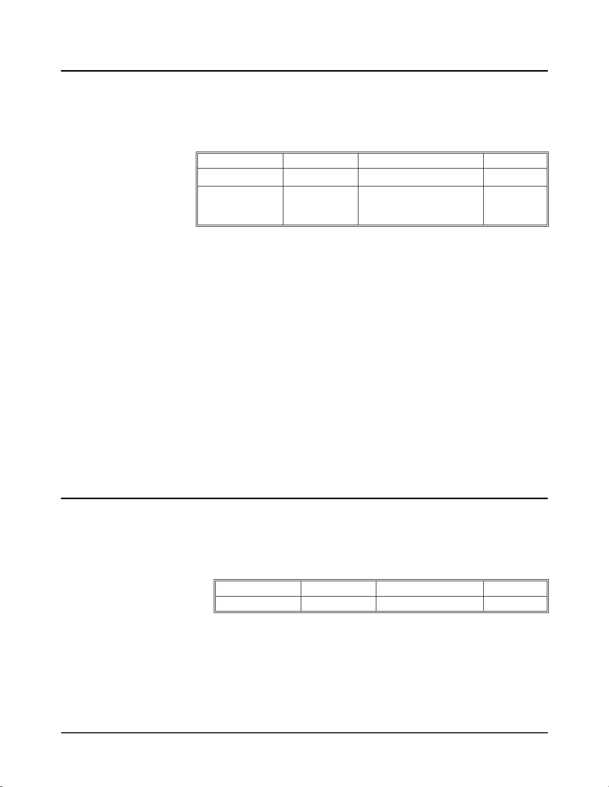
:VME:ADDRess
MEMory:VME:ADDRess [<base
VME memory in the system which can then be used to st ore block data in commands
with the
:TRACe keyword.
>]<
address> establishes the address of add-on
Parameters
Parameter Name Parameter Type Range of Values Default
<base>
<address>
Discrete none, #H, #Q, or #B Decimal
Numeric
or
Discrete
200000
MIN or MAX
–DFFFF8
16
16
None
Comments •base specifies the numeric format as decimal, hexadecimal, octal, or binary.
IEEE-488.2 specifies the following values for this parameter:
Decimal = no parameter
Hexadecimal = #H
Octal = #Q
Binary = #B
•Valid values for base and address are #H200000 (2,097,152 decimal) through
#HDFFFF8 (14,680,056 decimal).
•For this memory to actually be used it must also have a defined length and
have been turned ON using the
MEMory:VME:STATe command.
Example MEM:VME:ADDR #H200000 sets the starting VME address to 200000
:VME:ADDRess?
Parameters
Comments •This command always returns the address in decimal format.
•Related Commands: [SOURce:]DIGital:TRACe:DEFine,
MEMory:VME:ADDress?, MEMory:VME:SIZE, MEMory:VME:STATe
•*RST Condition: #H200000
.
16
MEMory:VME:ADDRess? [<MIN|MAX>] queries for the current VME memory
address. The optional par ameter lets you query for the fix ed minimum o r maximum
address.
Parameter Name Parameter Type Range of Values Default
MIN|MAX Discrete none, MIN, or MAX None
•The address returned using MIN is always 2,097,152.
•The address returned using MAX is always 14,680,056.
•Related Commands: MEMory:VME:ADDRess, MEMory:VME:SIZE?,
MEMory:VME:STATe?
HP E1330B Digital I/O Module Command Reference 69Chapter 5
Page 70

:VME:SIZE
Parameters
MEMory:VME:SIZE [<base>]<size> sets the size, in bytes, of the extern al memory.
Parameter Name Parameter Type Range of Values Default
Comments •Address plus size must not exceed #HE00000.
:VME:SIZE?
<base>
<
size>
Discrete none, #H, #Q, or #B Decimal
Numeric
or
Discrete
000000
MIN or MAX
- C00000
16
or
16
None
None
•base specifies the numeric format as decimal, hexadecimal, octal, or binary.
IEEE-488.2 specifies the following values for this parameter:
Decimal = no parameter
Hexadecimal = #H
Octal = #Q
Binary = #B
•Related Commands: MEMory:VME:ADDRess?, MEMory:VME:SIZE?,
MEMory:VME:STATe?
•*RST Condition: #H000000.
MEMory:VME:SIZE? [<MIN|MAX>] queries for the cu rrent VME memory si ze.
The optional parameter lets you query for the fixed maximum or minimum VME
memory size.
Parameters
Parameter Name Parameter Type Range of Values Default
MIN|MAX Discrete none, MIN, or MAX None
Comments •This command alw ays returns the memory size in decimal format.
•The size returned using MIN is always 0.
•The size returned using MAX is always 12582912.
•Related Commands: MEMory:VME:ADDRess?, MEMory:VME:SIZE,
MEMory:VME:STATe?
70 HP E1330B Digital I/O Module Command Chapter 5
Page 71

:VME:STATe
Parameters
Comments •Related Commands: [SOURce:]DIGital:TRACe:DEFine,
Example MEM:VME:STAT ON enables access to the VME memory.
:VME:STATe?
Parameters None.
MEMory:VME:STATe <state
storage.
Parameter Name Parameter Type Range of Values Default Value
<state>
[SOURce:]DIGital:TRACe[:DATA], MEMory:VME:ADDress,
MEMory:VME:SIZE
>
enables/disables the use of VME memory for
Boolean 0|1|ON|OFF 0|OFF
•*RST Condition: Set to OFF.
MEMory:VME:STATe? queries the state of the external memory.
Comments This command returns 0 or 1, indicating external memory is OFF or ON.
Related Commands:
MEMory:VME:ADDRess?, MEMory:VME:SIZE?
HP E1330B Digital I/O Module Command Reference 71Chapter 5
Page 72

[SOURce:] Subsystem
The [SOURce:] subsystem defines the command set for the Digital I/O module
output statements . It also def ines the state an d polarit y of the c ontrol line (CTL), the
polarity of the flag line (FLG), the hands haking mode, and handshake del ay for both
data input and output. The root command,
[SOURce:]
DIGital
:CONTrol
:DATA
n
:POLarity <POS|NEG>
:POLarity?
[:VALue] <0|1
[:VALue]?
n
[:BYTE]
m <0|1>
:BIT
m?
:BIT
:HANDshake
:DELay <
:DELay?
[:MODE] <NONE|LEADing|TRAiling
[:MODE]?
:POLarity <POS|NEG>
:POLarity?
:TRACe <
[:VALue] [<
[:VALue]?
:LWORd
m <0|1>
:BIT
m?
:BIT
:HANDshake
:DELay <
:DELay?
[:MODE] <NONE|LEADing|TRAiling
[:MODE]?
:POLarity <POS|NEG>
:POLarity?
:TRACe <
[:VALue] [<
[:VALue]?
or ON|OFF>
name>
base>]<value>
name>
base>]<value>
[SOURce:], is optional.
time>
|PULSe|PARTial|STRobe>
time>
|PULSe|PARTial|STRobe>
72 HP E1330B Digital I/O Module Command Chapter 5
Page 73

[SOURce:]
DIGital
:DATA
n
:WORD
m <0|1>
:BIT
m?
:BIT
:HANDshake
:DELay <
:DELay?
[:MODE] <NONE|LEADing|TRAiling
[:MODE]?
:POLarity <POS|NEG>
:POLarity?
:TRACe <
[:VALue] [<
[:VALue]?
:FLAG
n
:POLarity <POS|NEG>
:POLarity?
:HANDshake
:DELay <time>
:DELay?
[:MODE] <NONE|LEADing|TRAiling
[:MODE]?
:IO
n?
:TRACe
:CATalog?
[:DATA] <
[:DATA]? <
:DEFine <
:DEFine? <
:DELete
n
name>,<block_data>
name>,<size>,[<fill>]
:ALL
[:NAME] <
time>
|PULSe|PARTial|STRobe>
name>
base>]<value>
|PULSe|PARTial|STRobe>
name>
name>
name>
HP E1330B Digital I/O Module Command Reference 73Chapter 5
Page 74

DIGital:CONTroln:POLarity
[SOURce:]DIGital:CONTroln:POLarity <polarity> sets the CTL line voltage l evel
for logical true in port n to either TTL high for
NEGative polarity.
Parameters
Parameter Name Parameter Type Range of Values Default
POSitive polarity or TTL low for
CONTroln
<
polarity>
Comments •Control lines are always accessed by their 8-bit port number.
•:CONT roln is the keyword used for commands relating to the control (CTL)
line at port n. The port number n must be the last character of the keyword
without spaces.
•If n is omitted, port 0 is used.
•The c ontrol line is used with the flag line to handshake data to and from
peripherals.
•Related Commands: [SOURce:]DIGital:CONTroln:POLarity?
[SOURce:]DIGital:CONTroln[:VALue]
[SOURce:]DIGital:FLAGn:POLarity
[SOURce:]DIGital:FLAGn:POLarity?
•*RST Condition: POLarity = POSitive.
Example DIG:CONT0:POL POS sets logical true to TTL high on port 0 control line.
DIGital:CONTroln:POLarity?
Numeric none, 0, 1, 2, or 3 0
Discrete POSitive or NEGative None
,
,
,
[SOURce:]DIGital:CONTroln:POLarity? returns a three character string, either
POS or NEG, indicating the logical true co ndition of t he control (C TL) line at po rt n.
Parameters
Parameter Name Parameter Type Range of Values Default
CONTroln
Numeric none, 0, 1, 2, or 3 0
Comments •:CONTroln is the keyword used for commands relating to the control (CTL)
line at port n. The port number n must be the last character of the keyword
without spaces.
•If n is omitted, port 0 is used.
Example DIG:CONT0:POL? queries the state of the logical true condition on port 0.
74 HP E1330B Digital I/O Module Command Chapter 5
Page 75

DIGital:CONTroln[:VALue]
[SOURce:]DIGital:CONTroln[:VALue] <value> sets or clears the control line on
the selected port n.
Parameters
Parameter Name Parameter Type Range of Values Default
CONTroln
<
value>
Comments •This command is used to create custom handshakes when the HANDshake is
NONE.
set to
•:CONTroln is the keyword used for commands relating to the control (CTL)
line at port n. The port number n must be the last character of the keyword
without spaces.
•The c ontrol line is used with the flag line to handshake data to and from
peripherals.
•Related Commands: [SOURce:]DIGital:CONTroln:POLarity,
[SOURce:]DIGital:CONTroln:POLarity?, [SOURce:]DIGital:FLAGn:POLarity,
[SOURce:]DIGital:FLAGn:POLarity?
•*RST Condition: Clears the control line; i.e ., sets the contro l line t o logical 0.
Example DIG:CONT2 1 sets the 8-bit port 2 control line true.
DIGital:CONTroln[:VALue]?
[SOURce:]DIGital:CONTroln[:VALue]? reads the state of the control line on port
n and returns a 0 or 1, indicating the logical condition of the CTL line.
Numeric none, 0, 1, 2, or 3 0
Boolean 0 or 1, OFF or ON None
Parameters
Parameter Name Parameter Type Range of Values Default
CONTroln
Numeric none, 0, 1, 2, or 3 0
Comments •This command is only available when using the downloaded SCPI driver.
•This command is used to create custom handshakes when the HANDshake is
NONE.
set to
•The condition of the CTL line returned by this command is the logical true
value set by the
Example DIG:CONT2? returns the current state of the 8-bit port 2 control line.
DIGital:CONTroln:POLarity command.
HP E1330B Digital I/O Module Command Reference 75Chapter 5
Page 76

DIGital:DATAn[:type]:BITm
[SOURce:]DIGital:DATAn[:BYTE]:BITm <value> sets bit m on 8-bit port n.
[SOURce:]DIGital:DATAn:WORD:BITm <value> sets bit m on 16-bit port n.
[SOURce:]DIGital:DATAn:LWORd:BITm <value> sets bit m on 32-bit port n.
Parameters
Parameter Name Parameter Type Range of Values Default
DATA
BIT
value>
<
Comments •:DATAn and :BITm are the keywords used to write data to port n and bit m.
The port number n and bit number m must be the last character of the k eyword
without spaces.
n
m
Numeric BYTE
WORD
LWORd
Numeric BYTE
WORD
LWORd
Numeric 0 or 1 None
none, 0, 1, 2, or 3
none, 0 or 2
none or 0
0–7
0–15
0–31
0
0
•For 16-bit operations using :WORD, n must be 0 or 2.
•For 32-bit operations using :LWORd, n must be 0.
•The keyword :LW32 may be used instead of :LWORd when using the
download version of the SCPI driver.
•Related Commands: [SOURce:]DIGital:DATAn:POLarity,
[SOURce:]DIGital:DATAn[:VALue]
•*RST Condition: All ports are set for data input.
Example DIG:DATA3:BIT4 1 sets bit 4 (the 5th bit) of port 3 to logical 1.
76 HP E1330B Digital I/O Module Command Chapter 5
Page 77

DIGital:DATAn[:type]:BITm?
[SOURce:]DIGital:DATAn[:BYTE]:BITm? returns a 0 or 1 indicating the current
programmed state of bit m on 8-bit port n.
[SOURce:]DIGital:DATAn:WORD:BITm? returns a 0 or 1 indicating the current
programmed state of bit m on 16-bit port n.
[SOURce:]DIGital:DATAn:LWORd:BITm? returns a 0 or 1 indicating the curren t
programmed state of bit m on 32-bit port n.
Parameters
Parameter Name Parameter Type Range of Values Default
DATAn
BITm
Numeric BYTE
WORD
LWORd
Numeric BYTE
WORD
LWORd
none, 0, 1, 2, or 3
none, 0 or 2
none or 0
0–7
0–15
0–31
0
0
Comments •This command is only available when using the downloaded SCPI driver.
•This command performs a readback of the data line register, not the actual
condition of the data lines.
•The keyword :LW32 may be used instead of :LWORd when using the
download version of the SCPI driver.
•:DATAn and :BITm are the keywords used to write data to port n and bit m.
The port number n and bit number m must be the last character of the k eyword
without spaces.
•For 16-bit operations using :WORD, n must be 0 or 2.
•For 32-bit operations using :LWORd, n must be 0.
•Related Commands: [SOURce:]DIGital:DATAn:POLarity,
[SOURce:]DIGital:DATAn[:VALue]
Example DIG:DATA3:BIT4:VAL? returns a 0 or 1 indicating the last pr ogrammed state o f bit
4 on port 3.
HP E1330B Digital I/O Module Command Reference 77Chapter 5
Page 78

DIGital:DATAn[:type]:HANDshake:DELay
[SOURce:]DIGital:DATAn[:BYTE]:HANDshake:DELay <time> sets the delay
between data output and control line for data output at 8-bit port n.
[SOURce:]DIGital:DATAn:WORD:HANDshake:DELay <time> sets the delay
between data output and control line for data output at 16-bit port n.
[SOURce:]DIGital:DATAn:LWORd:HANDshake:DELay <time> sets the delay
between data output and the control line for data output at 32-bit port n.
Parameters
Parameter Name Parameter Type Range of Values Default
DATAn
<time>
Numeric BYTE
WORD
LWORd
Numeric
Discrete MIN|MAX|DEF
none, 0, 1, 2, or 3
none, 0 or 2
none or 0
2 µs to 15 µs
20
µs to 150 µs
200
µs to 1.5 ms
2ms to 15ms
0
None
Comments •This command is r elated to the h andshake mod e in use. Chapter 3 describ es the
handshake modes and timing.
•This command sets strobe pulse width for input and output STRobe
handshakes.
•The delay time must be set to the same value on all ports used in a multiple
port operation.
•MAX sets a 15ms delay. DEF sets 2µs delay. MIN sets 0.0 delay and is illegal
for PULse or STRobe handshake modes.
•DIGital:DATAn:HANDshake[:MODE] NONE command ignores any
programmed delay time. For all other modes of handshaking, 2
minimum recommended.
µs is the
•Specific bands of delay settings are NOT allowed. These are:
µs > <time
0
µs> <time
15
The controller us es a rounded-up value f or
> <
2µs150µs> <time
> <
20 µs1.5ms> <time
> <
<time
200µs
> <
2.0ms
>
if these valu es are specified.
•The keyword :LW32 may be used instead of :LWORd when using the
download version of the SCPI driver.
•DIGital:DATAn[:type]:HANDshake is the sequence used for commands
relating to data handshaking at ports defined by n. The port number n must be
the last character of the keyword without spaces.
•Related Commands: [SOURce:]DIGital:CONTroln:POLarity,
[SOURce:]DIGital:CONTroln[:VALue], [SOURce:]DIGital:FLAGn:POLarity,
[SOURce:]DIGital:HANDshaken[:MODE]
•*RST Condition: Delay is set to 2µs.
Example DIG:HAND3:DEL . 005 sets the delay between the data output and the assertion of
the control line to true on 8-bit port 3 to 5ms.
78 HP E1330B Digital I/O Module Command Chapter 5
Page 79

DIGital:DATAn[:type]:HANDshake:DELay?
[SOURce:]DIGital:DATAn[:BYTE]:HANDshake:DELay? queries for the delay
time between data output and the control line for data output at 8-bit port n and
returns a decimal number between 0 and .015.
[SOURce:]DIGital:DATAn:WORD:HANDshake:DELay? queries for the delay
time between data output and the control line for data output at 16-bit port n and
returns a decimal number between 0 and .015.
[SOURce:]DIGital:DATAn:LWORd:HANDshake:DELay? queries for the delay
time between data output and the control line for data output at 32-bit port n and
returns a decimal number between 0 and .015.
Parameters
Parameter Name Parameter Type Range of Values Default
DATAn
MIN|MAX|DEF Discrete None or MIN|MAX|DEF None
Numeric BYTE
WORD
LWORd
none, 0, 1, 2, or 3
none, 0 or 2
none or 0
0
Comments •The delay time must be set to the same value on all ports used in a multiple
port operation.
•The keyword :LW32 may be used instead of :LWORd when using the
download version of the SCPI driver.
•DIG:DATAn[:type]:HANDshake is the sequence used for commands relating
to data handshaking at ports defined by n. The port number n must be the last
character of the keyword without spaces.
•MIN or DEF returns 0.000002. MAX returns 0.015.
HP E1330B Digital I/O Module Command Reference 79Chapter 5
Page 80

DIGital:DATAn[:type]:HANDshake[:MODE]
[SOURce:]DIGital:DATAn[:BYTE]:HANDshake[:MODE] <mode> selects the
type of handshake and defines the timing relationship between the control (CTL)
line, the flag (FLG) line , and when data is transf erred in eit her direction bet ween the
Digital I/O Module and a peripheral on the 8-bit port n.
[SOURce:]DIGital:DATAn:WORD:HANDshake[:MODE] <mode> selects the
handshake mode used on the 16-bit port n.
[SOURce:]DIGital:DATAn:LWORd:HANDshake[:MODE] <mode> selects the
handshake mode used on the 32-bit port n.
Parameters
Parameter Name Parameter Type Range of Values Default
DATAn
<mode>
Numeric BYTE
WORD
LWORd
Discrete NONE, LEADing, TRAiling,
PULse, PARTial, or STRobe
none, 0, 1, 2, or 3
none, 0 or 2
none or 0
0
NONE
•Handshake modes are described in Chapter 3.
•The handshake mode must be the same on all ports used in a multiple port
operation.
•The keyword :LW32 may be used instead of :LWORd when using the
downloaded version of the SC PI driver.
•DIGital:DATAn[:type]HANDshake is the sequence used for commands
relating to data handshaking at port n. The port number n must be the last
character of the keyword without spaces.
• NONE deletes all automatic data handshaking between the Digital I/O module
and the peripheral. For custom handshaking, the control and the flag lines are
controlled by the
MEASure:DIGital:FLAGn commands.
[SOURce:]DIGital:CONTroln and
•Related Commands: [SOURce:]DIGital:CONTroln:POLarity,
[SOURce:]DIGital:CONTroln[:VALue], [SOURce:]DIGital:FLAGn:POLarity,
[SOURce:]DIGital:HANDshaken:DELay
•*RST Condition: Mode is NONE on all ports.
Example DIG:DATA3:HAND LEAD sets the handshake mode to LEADing on 8-bit port 3.
80 HP E1330B Digital I/O Module Command Chapter 5
Page 81

DIGital:DATAn[:type]:HANDshake[:MODE]?
[SOURce:]DIGital:DATAn[:BYTE]:HANDshake[:MODE]? returns a string
indicating the type of handshake set on the 8-bit port n.
[SOURce:]DIGital:DATAn:WORD:HANDshake[:MODE]? returns a string
indicating the type of handshake set on the 16-bit port n.
[SOURce:]DIGital:DATAn:LWORd:HANDshake[:MODE]? returns a string
indicating the type of handshake set on the 32-bit port n.
Parameters
Parameter Name Parameter Type Range of Values Default
DATAn
Numeric BYTE
WORD
LWORd
none, 0, 1, 2, or 3
none, 0 or 2
none or 0
Comments •The keyword :LW32 may be used instead of :LWORd when using the
download version of the SCPI driver.
•The handshake mode must be the same on all ports used in a multiple port
operation.
•This command will return one of the following strings:
NONE
LEAD
TRA
PULS
PART
STR
•:DAT An[:type]HANDshake? is the sequence used for commands relating to
data handshaking at port n. The port number n must be the last charac ter of the
keyword without spaces.
•Related Commands: [SOURce:]DIGital:CONTroln:POLarity,
[SOURce:]DIGital:CONTroln[:VALue], [SOURce:]DIGital:FLAGn:POLarity,
[SOURce:]DIGital:HANDshaken:DELay
0
•*RST Condition: Mode is NONE on all ports.
Example DIG:DATA3:HAND? returns the handshake mode set on port 3.
HP E1330B Digital I/O Module Command Reference 81Chapter 5
Page 82

DIGital:DATAn[:type]:POLarity
[SOURce:]DIGital:DATAn[:BYTE]:POLarity <polarity> sets the data line voltage
level for logi cal true in the 8-bit p ort n to either TTL high for
TTL low for
[SOURce:]DIGital:DATAn:WORD:POLarity <polarity> sets the data line voltage
level for logical true in t he 16-bi t port n to ei ther TTL high for
TTL low for
[SOURce:]DIGital:DATAn:LWORd:POLarity <polarity> sets the data line voltage
level for logical true in t he 32-bi t port n to ei ther TTL high for
TTL low for
Parameters
Parameter Name Parameter Type Range of Values Default
Comments •:DATAn is the keyword used for commands relating to the data lines at port n.
The port number n must be the last character of the keyword without spaces.
NEGative polarity.
NEGative polarity.
NEGative polarity.
n
DATA
polarity>
<
POSitive pola ri ty or
POSitive polarity or
POSitive polarity or
Numeric BYTE
WORD
LWORd
Discrete POSitive or NEGative None
none, 0, 1, 2, or 3
none, 0 or 2
none or 0
0
•Related Commands: [SOURce:]DIGital:DATAn:BITm,
[SOURce:]DIGital:DATAn:POLarity?, [SOURce:]DIGital:DATAn[:VALue]
•*RST Condition: POLarity = POSitive
Example DIG:DATA0:POL POS sets logical true to TTL high on 8-bit port 0 data lines.
DIGital:DATAn[:type]:POLarity?
[SOURce:]DIGital:DATAn[:BYTE]:POLarity? returns a string, either POS or NEG,
indicating the logical true condition of the data lines of 8-bit port n.
[SOURce:]DIGital:DATAn:WORD:POLarity? returns a string, either POS or NEG,
indicating the logical true condition of the data lines of 16-bit port n.
[SOURce:]DIGital:DATAn:LWORd:POLarity? returns a string, either POS or
NEG, indicating the logical true condition of the data lines of 32-bit port n.
Parameters
Parameter Name Parameter Type Range of Values Default
DATAn
Numeric BYTE
WORD
LWORd
none, 0, 1, 2, or 3
none, 0 or 2
none or 0
0
Example DIG:DATA0:POL? returns the state of the logical true condition on port 0 as either
POS or NEG.
82 HP E1330B Digital I/O Module Command Chapter 5
Page 83

DIGital:DATAn[:type]:TRACe
[SOURce:]DIGital:DATAn[:BYTE]:TRACe <name> writes the named block of
data to 8-bit port n whenever the port is ready to start a new handshake.
[SOURce:]DIGital:DATAn:WORD:TRACe <name> writes the named block of data
to 16-bit port n whenever the port is ready start a new h andshake.
[SOURce:]DIGital:DATAn:LWORd:TRACe <name> writes the named block of
data to 32-bit port n whenever the port is ready to start a new handshake.
Parameters
Parameter Name Parameter Type Range of Values Default
n
DATA
Numeric BYTE
WORD
LWORd
none, 0, 1, 2, or 3
none, 0 or 2
none or 0
0
<name>
String Name of user memory block
(maximum 12 characters)
None
Comments •The keyword :LW32 may be used instead of :LWORd when using the
download version of the SCPI driver.
•:DATAn and :TRACe are the keywords used to write data to port n from block
name. The port number n must be the last character of the keyword without
spaces.
•Related Commands: [SOURce:]DIGital:DATAn:POLarity,
[SOURce:]DIGital:DATAn[:VALue]
•*RST Condition: All ports are set for data input.
Example DIG:DATA2:TRAC:WORD first_block writes data from the user memory block
first_block to 16-bit port 2.
HP E1330B Digital I/O Module Command Reference 83Chapter 5
Page 84

DIGital:DATAn[:type][:VALue]
[SOURce:]DIGital:DATAn[:BYTE][:VALue] [<base>]<value> writes data to 8-bit
port n. Values can be binary, octal, decimal, or hexadecimal.
[SOURce:]DIGital:DATAn:WORD[:VALue] [<base>]<value> wri tes data to 1 6-bit
port n. Values can be binary, octal, decimal, or hexadecimal.
[SOURce:]DIGital:DATAn:LWORd[:VALue] [<base>]<value> writes data to
32-bit port n. Values can be binary, octal, decimal, or hexadecimal.
Parameters
Parameter Name Parameter Type Range of Values Default
n
DATA
base>
<
<value
>
Numeric BYTE
WORD
LWORd
Discrete None, #H, #Q, or #B Decimal
Numeric BYTE
WORD
LWORd
none, 0, 1, 2, or 3
none, 0 or 2
none or 0
7
to (28-1)
-2
-215 to (216-1)
31
-2
to (231-1)
0
None
Comments •The keyword :LW32 may be used instead of :LWORd when using the
download version of the SCPI driver.
•base specifies the numeric format as decimal, hexadecimal, octal, or binary.
IEEE-488.2 specifies the following values for this parameter:
Decimal = no parameter
Hexadecimal = #H
Octal = #Q
Binary = #B
•:DATAn is the keyword used for commands relating to data output at port n.
The port number n must be the last character of the keyword without spaces.
•Related Commands: [SOURce:]DIGital:DATAn:BITm,
[SOURce:]DIGital:DATAn:POLarity
•*RST Condition: All ports are set for data input.
Examples DIG:DATA3 27 writes the binary equivalent of the decimal number 27 (00011011)
to 8-bit port 3.
DIG:DATA3 #B00011011 writes the same byte of data as in the example above to
port 3, but in binary format.
84 HP E1330B Digital I/O Module Command Chapter 5
Page 85

DIGital:DATAn[:type][:VALue]?
[SOURce:]DIGital:DATAn[:BYTE][:VALue]? returns the programmed state of
8-bit port n as a decimal number between 0 and 255.
[SOURce:]DIGital:DATAn:WORD[:VALue]? returns the programmed state of
16-bit port n as a decimal number between -32768 and 32767.
[SOURce:]DIGital:DATAn:LWORd[:VALue]? returns the programmed state of
32-bit port n as a decimal number between -2
Parameters
Parameter Name Parameter Type Range of Values Default
31
and (231- 1).
DATAn
Numeric BYTE
WORD
LWORd
none, 0, 1, 2, or 3
none, 0 or 2
none or 0
0
Comments •This command is only available when using the downloaded SCPI driver.
•The keyword :LW32 may be used instead of :LWORd when using the
download version of the SCPI driver.
•This command returns the programmed state of the data lines, not the actual
state of the d ata lines.
•:DATAn is the keyword used for commands relating to data output at port n.
The port number n must be the last character of the keyword without spaces.
•Related Commands: [SOURce:]DIGital:DATAn:BITm,
[SOURce:]DIGital:DATAn:POLarity
•*RST Condition: All ports are set for data input.
Example DIG:DATA3? returns the decimal equivalent of the data lines on 8-bit port 3.
HP E1330B Digital I/O Module Command Reference 85Chapter 5
Page 86

DIGital:FLAGn:POLarity
[SOURce:]DIGital:FLAGn:POLarity <polarity> sets the voltage level for logical
true to either TTL high,
line.
Parameters
Parameter Name Parameter Type Range of Values Default
POSitive, or TTL low, NEGative on the FLG handshake
FLAGn
<
polarity>
Comments •:FLAGn is the keyword u sed for commands rela ting to the flag line at port n.
The port number n must be the last character of the keyword without spaces.
•Related Commands: [SOURce:]DIGital:CONTroln:POLarity,
[SOURce:]DIGital:CONTroln:POLarity?, [SOURce:]DIGital:FLAGn:POLarity?
•*RST Condition: POLarity = POSitive
Example DIG:FLAG0:POL POS sets logical true to TTL high on the port 0 flag line.
DIGital:FLAGn:POLarity?
[SOURce:]DIGital:FLAGn:POLarity? re turns a string, eith er POS or NEG,
indicating the logical true condition of the flag (FLG) line.
Parameters
Parameter Name Parameter Type Range of Values Default
FLAG
Numeric none, 0, 1, 2, or 3 0
Discrete POSitive or NEGative None
n
Numeric none, 0, 1, 2, or 3 0
Example SOURCE:DIGITAL:FLAG0:POLARITY? uses long commands to query the state o f
the logical true condition on port 0.
DIG:FLAG0:POL? performs the same function as the example above with short
commands.
86 HP E1330B Digital I/O Module Command Chapter 5
Page 87

DIGital:HANDshaken:DELay
[SOURce:]DIGital:HANDshaken:DELay <time> sets the time between data valid
and the assertion of the cont rol line to TRUE for port n. This f orm of the command
operates on 8-bit ports only.
Parameters
Parameter Name Parameter Type Range of Values Default
HANDshaken
<
time
>
Numeric None, 0, 1, 2, or 3 None
Numeric
Discrete MIN|MAX|DEF
2µs to 15µs
20
µs to 150µs
200
µs to 1.5ms
2ms to 15ms
Comments •:HANDshaken is the keyword used for commands relating to data
handshaking at port n. The port number n must be the last character of the
keyword without spaces.
•This command sets the strobe pulse width for both input and output STRobe
handshakes.
•The delay time must be set to the same value on all ports used in a multiple
port operation.
•MAX sets a 15ms delay. DEF sets 2µs delay. MIN sets a delay of 0, and is
illegal for PULse and STRobe handshakes.
•DIGital:HANDshaken NONE command sets the delay to 0. For all other
modes of handshaking, 2
µs is the minimum.
•Specific bands of delay settings are NOT allowed. These are:
µs > <time
0
µs> <time
15
The controller us es a rounded-up value f or
> <
2µs150µs> <time
> <
20 µs1.5ms> <time
> <
<time
200µs
> <
2.0ms
>
if these valu es are specified.
None
•Related Commands: [SOURce:]DIGital:CONTroln
[SOURce:]DIGital:CONTroln
[SOURce:]DIGital:HANDshaken
[:VALue]
[:MODE]
, [SOURce:]DIGital:FLAGn
:POLarity
,
:POLarity
,
•*RST Condition: Delay is set to 2 µs.
Example DIG:HAND3:DEL .005 sets the delay between the data output and the assertion of
the control line to true on 8-bit port 3 to 5 ms.
HP E1330B Digital I/O Module Command Reference 87Chapter 5
Page 88
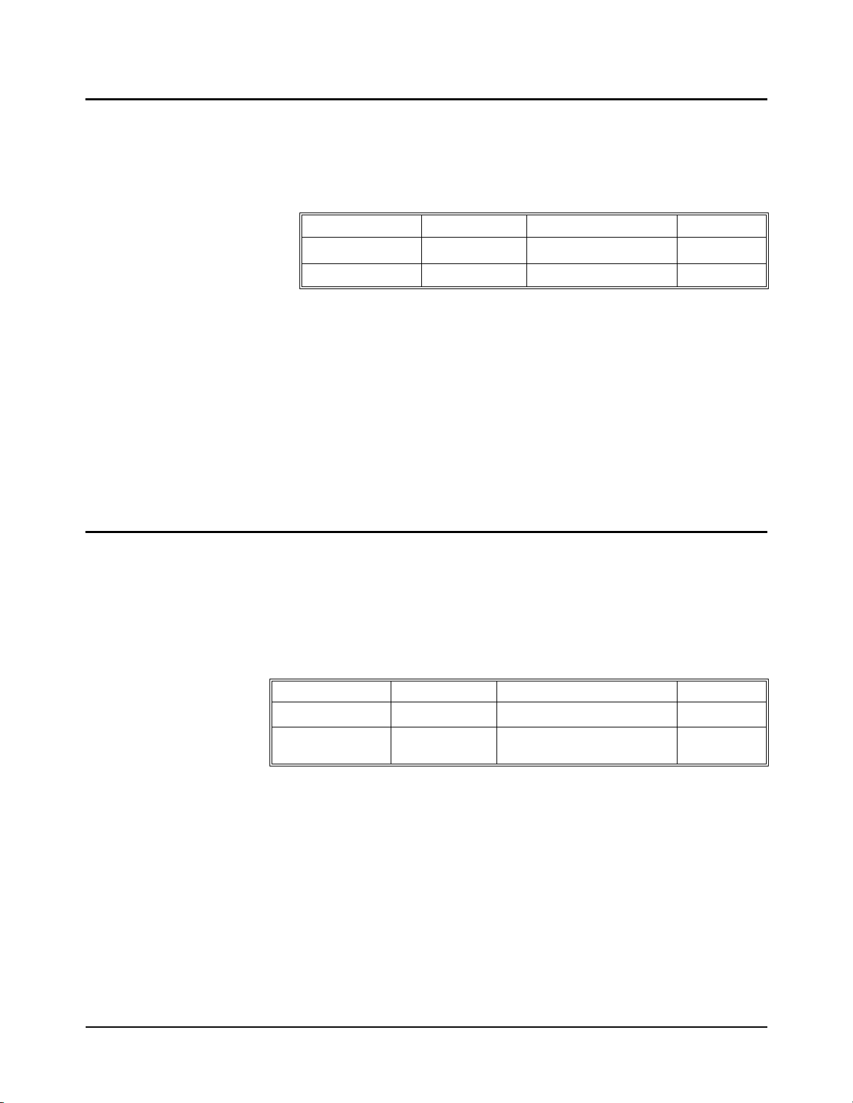
DIGital:HANDshaken:DELay?
[SOURce:]DIGital:HANDshaken:DELay? queries for the ti me be tween data valid
and the assertion of the con trol li ne to TRUE. Thi s command ope rates on 8-bit por ts
and returns a decimal value between 0 and 0.015.
Parameters
Parameter Name Parameter Type Range of Values Default
HANDshaken
MIN|MAX|DEF Discrete None or MIN|MAX|DEF None
Comments •The delay time must be set to the same value on all ports used in a multiple
port operation.
•:HANDshaken is the keyword used for commands relatin g to data
handshaking at 8-bit port n. The port number n must be the last character of the
keyword without spaces.
•MIN or DEF returns 0.000002. MAX returns 0.015.
Example DIG:HAND0:DEL? queries the delay time between data valid and the assertion of
the control line to TRUE on 8-bit port 0.
DIGital:HANDshaken[:MODE]
[SOURce:]DIGital:HANDshaken[:MODE] <mode> selects the type of handshake
mode to use to transfer data in either direction between the Digital I/O module and a
peripheral on 8-bit port n. Handshakes are i nitiated by execution of a
MEASure:DIGital:DATAn
or
operates only on 8-bit ports.
Numeric None, 0, 1, 2, or 3 0
DIGital:DATAn
?
command. This form of the HANDshake command
Parameters
Parameter Name Parameter Type Range of Values Default
HANDshaken
mode>
<
Numeric None, 0, 1, 2, or 3 0
Discrete NONE, LEADing, TRAiling,
PULSe, PARTial, or STRobe
NONE
Comments •:HANDshaken is the keyword used for commands relating to data
handshaking at port n. The 8- bit port number n must be the last character of the
keyword without spaces.
•NONE deletes all automatic data handshaking between the Digital I/O Module
and peripheral. For custom handshaking, the control and flag lines are
controlled by the
DIGital:CONTroln and DIGital:FLAGn commands.
•Related Commands: [SOURce:]DIGital:HANDshaken:DELay,
[SOURce:]DIGital:CONTroln:POLarity
•*RST Condition: Mode is NONE on all ports.
Example DIG:HAND3 LEAD sets the handshake mode to LEADing on 8-bit port 3.
88 HP E1330B Digital I/O Module Command Chapter 5
Page 89

DIGital:HANDshaken[:MODE]?
[SOURce:]DIGital:HANDshaken[:MODE]? returns a s tring indicating the current
handshake mode of 8-bit port n. This form of the
only on 8-bit ports.
Parameters
Parameter Name Parameter Type Range of Values Default
HANDshake command operates
Comments •This command will return one of the following strings:
DIGital:IOn?
Parameters
HANDshaken
Numeric None, 0, 1, 2, or 3 0
NONE
LEAD
TRA
PULS
PART
STR
•:HANDshaken is the keyword used for commands relat ing to data
handshaking at port n. The port number n must be the last character of the
keyword without spaces.
[SOURce:]DIGital:IOn
line on port n.
?
returns a 0 or 1 i ndi cating the current condition of the I/ O
Parameter Name Parameter Type Range of Values Default
IOn
Numeric None, 0, 1, 2, or 3 0
Comments •This command is only available when using the downloaded SCPI driver.
•The I/O line’s polarity is fixed and is as follows:
-- When Digital I/O module is programmed to output data, the I/O
low.
-- When Digital I/O module is programmed to input data, the I/O
high.
line is set
line is set
•:IOn is the keyword used for commands relating to the I/O line at port n. The
port number n must be the last character of the keyword without spaces.
HP E1330B Digital I/O Module Command Reference 89Chapter 5
Page 90

DIGital:TRACe:CATalog?
[SOURce:]DIGital:TRACe:CATalog? lists the currently available data blocks.
Parameters None.
Comments •This command catalogs all blocks in VME memory and all blocks in the
mainframe system memory .
•The command returns a string.
Example DIG:TRAC:CAT? would return this string if both alpha and beta had been
previously d efined; "alpha","beta".
DIGital:TRACe[:DATA]
[SOURce:]DIGital:TRACe[:DATA] <name>,<block_data> writes a block of data
to a previously defined user memory block.
Parameters
Parameter Name Parameter Type Range of Values Default
<name
>
<block_data>
String Name of user memory
block (maximum 12
characters)
Numeric/String Numeric header and
ASCII block data
None
None
Comments •<name> must have been previously defined by a DIGital:TRACe:DEFine
command.
•The maximum length for <name> is 12 characters.
•<block_data> is of the form <#digits
<#digits> tells how many digits are used to define <length
<length
<block
Example DIG:TRAC:DATA first_block,#210ABCDEFGHIJ sends the data “ABCDEFGHIJ”
to the user memory blo ck first_block. Since the ASCII characte r A has a decimal
value of 65, the equivalent of 65 is stor ed in the first byte of first_block (a nd s o on).
>
tells how many bytes are to be transferred in <block>;
>
contains the actual data to transfer.
><
length><block> where:
>
;
90 HP E1330B Digital I/O Module Command Chapter 5
Page 91

DIGital:TRACe[:DATA]?
[SOURce:]DIGital:TRACe[:DATA]? <name
previously defined user memory block.
Parameters
Parameter Name Parameter Type Range of Values Default
Comments •name must have been previously defined by a DIGital:TRACe:DEFine
command.
•The maximum length for name is 12 characters.
Example DIG:TRACe? first_block reads data from a block named first_block. If the
previous command example is sent, this command will return the string
#210ABCDEFGHIJ.
DIGital:TRACe:DEFine
[SOURce:]DIGital:TRACe:DEFine <name>,<size>,[<fill>] defines a block of data
as a user memo ry block, names th e block for future reference, and fills the block with
the last parameter. If the last parameter is absent, the block is filled with zeros.
<name
>
reads a block of data from a
>
String Name of user memory blo ck
(maximum 12 characters)
None
Parameters
Parameter Name Parameter Type Range of Values Default
name
<
size>
<
<
fill>
>
String Name of user memory blo ck
(maximum 12 characters)
Numeric Up to 12 Mbytes (depending
on memory installed)
Numeric 0–255 0
None
None
Comments •The firmware can hand le blocks wi th a tot al memory sp ace of up t o 12 Mbytes
of memory space. The actual amount available depends on the memory
installed.
•If the MEMory:VME:STATe ON command has been used, this command will
create blocks in the external add-on memory.
MEMory:VME:STATe OFF command has been used, this command will
If the
create blocks in the system memory.
Example DIG:TRAC:DEF first_block, 256 defines a 256 byte user memory block named
first_block and fills each byte with a zero.
HP E1330B Digital I/O Module Command Reference 91Chapter 5
Page 92

DIGital:TRACe:DEFine?
[SOURce:]DIGital:TRACe:DEFine? <name> returns the size of a previously
defined user memory block in byte s. The command return s a deci mal nu mber i n the
range of 0 to 12,582,912.
Parameters
Parameter Name Parameter Type Range of Values Default
<name
>
Comments •<name> must have been previously defined by a DIGital:TRACe:DEFine
command. The maximum length for
DIGital:TRACe:DELete:ALL
[SOURce:]DIGital:TRACe:DELete:ALL deletes all previously defined user
memory data blocks.
Parameters None.
DIGital:TRACe:DELete[:NAME]
[SOURce:]DIGital:TRACe:DELete[:NAME] <name> deletes a previously defined
user memory data block.
String Name of user memory blo ck
(maximum 12 characters)
<name> is 12 characters.
None
Parameters
Parameter Name Parameter Type Range of Values Default
<
name
>
String Name of user memory blo ck
(maximum 12 characters)
None
Comments <name> must have been previousl y defined by a DIGital:TRACe:DEFine command.
The maximum length for
<name> is 12 characters.
Example DIG:TRACe:DEL first_block deletes a user memory block named first_block.
92 HP E1330B Digital I/O Module Command Chapter 5
Page 93

The STATus subsystem controls the SCPI-defined Operation and Questionable
Signal Status Registers and the Standard Event Registers. Each is comprised of a
Condition Register, an Event Register, an enable mask, and transition filters.
Each Status Register works as foll ows: when a condit ion occu rs, the a ppropri ate bi t
in the Condition Register is set or cleared. If the correspond ing transition filter is
enabled for that bit, the same bit is set in the associated Event Register. The contents
of the Event Register and t he enable mask are l ogically ANDed bit-f or-bit; if any bi t
of the result is set, the summary bit for that register is set in the status byte. The status
byte summary b it for the Operation Status Register is bit 7; for the Questionable
Signal Status Register, bit 3; and for the Standard Event Register, bit 5.
Syntax STATus
:OPERation
:PRESet
:QUEStionable
STATus Subsystem
:CONDition?
:ENABle
:ENABle?
[:EVENt]?
:CONDition?
:ENABle
:ENABle?
[:EVENt]?
Note This subsystem is provided for compatibility. The Digital I/O module does not use
the Operation Status or Questionable Status Registers.
HP E1330B Digital I/O Module Command Reference 93Chapter 5
Page 94

:OPERation:CON Dition ?
STATus:OPERation:CONDition? returns the contents of the Operation Status
Condition Register. Readi ng the regi ster does no t affect its contents . This command
does not affect the HP E1330 Digital I/O module.
:OPERation:ENABle
STATus:OPERation:ENABle <mask> specifies which bits of t he associated Even t
Register are included in its summary bit. The summary bit is the bit-for-bit logical
AND of the Event Register and the unmasked bit(s). This co mman d does not affect
the HP E1330 Digital I/O module.
Parameters
Parameter Name Parameter Type Range of Values Default
The non-decimal numeric forms are the #H, #Q, or #B formats specified by
IEEE-488.2.
mask
<
>
Numeric or
non-decimal
numeric
0 through +32767 None
:OPERation:ENA B le?
STATus:OPERation:ENABle? returns the mask set for the Operation Status
Register. This command does not affect the HP E1330 Digital I/O module.
:OPERation[:EVENt]?
STATus:OPERation[:EVENt]? returns the contents of the Operation Event Status
Register. Reading the register clears all bits in the register. This command does not
affect the HP E1330 Digital I/O module.
:PRESet
STATus:PRESet clears both the Operation Status Enable and Questionable Status
Enable Registers. This command does not affect the HP E1330 Digital I/O module.
94 HP E1330B Digital I/O Module Command Chapter 5
Page 95

:QUEStionable:CONDition?
STATus:QUEStionable:CONDition? returns the contents of the Questionable
Status Condition Register. Reading the register does not affect its contents. This
command does not affect the HP E1330 Digital I/O module.
:QUEStionable:ENABle
STATus:QUEStionable:ENABle <mask> specifies which bits of the associated
Event Register are included in its summary bit. The summary bit is the bit-for-bit
logical AND of the Event Reg ister and th e unmasked bit( s). This command doe s not
affect the HP E1330 Digital I/O module.
Parameters
Parameter Name Parameter Type Range of Values Default
<
The non-decimal numeric forms are the #H, #Q, or #B formats specified by
IEEE-488.2.
mask
>
Numeric or
non-decimal
numeric
0 through +32767 None
:QUEStionable:ENABle?
STATus:QUEStionable:ENABle? returns the mask set for the Quest ionable Status
Register. This command does not affect the HP E1330 Digital I/O module.
:QUEStionable[:EVENt]?
STATus:QUEStionable[:EVENt]? returns the contents of the Questionable Status
Event Register. Reading the register clears all bits in the register. This command
does not affect the HP E1330 Digital I/O module.
HP E1330B Digital I/O Module Command Reference 95Chapter 5
Page 96
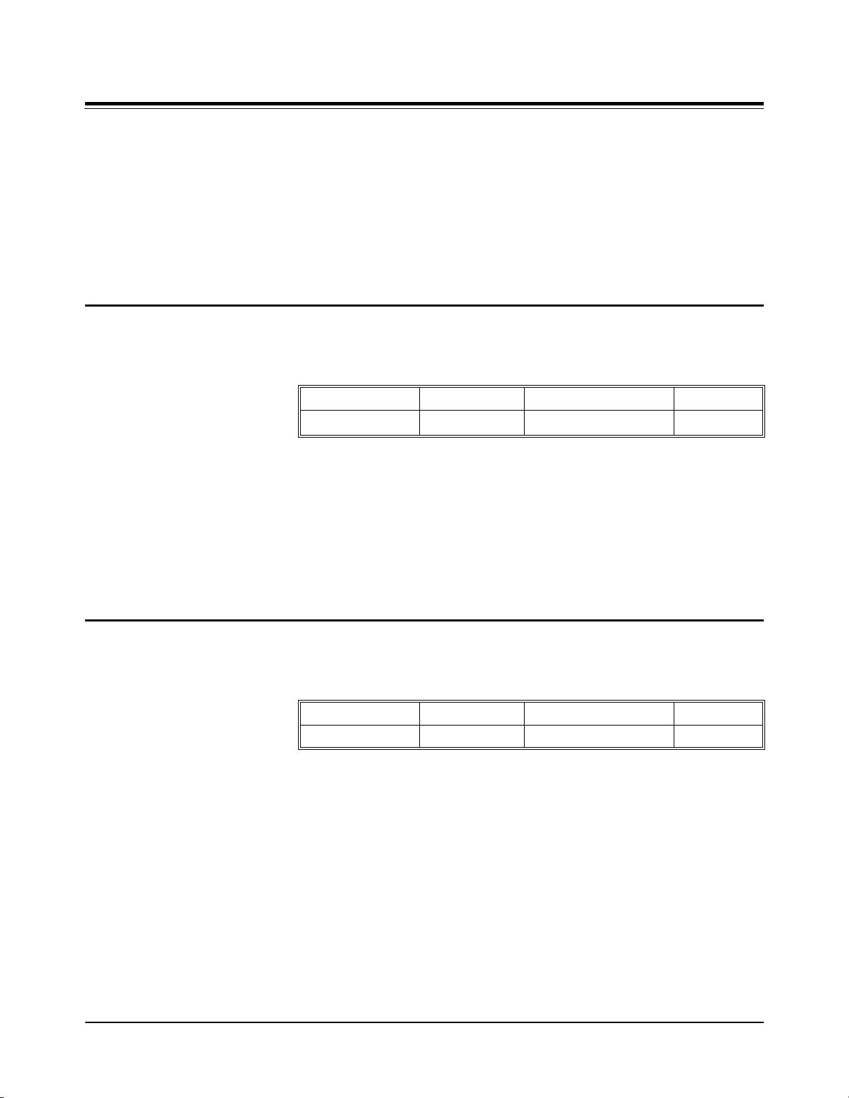
Syntax SYSTem
:CDEScription?
Parameters
SYSTem Subsystem
The SYSTem subsystem returns information about the module.
:CDEScription? <
:CTYPe? <
:ERRor?
:VERsion?
SYSTem:CDEScription? <number> returns the module description.
Parameter Name Parameter Type Range of Values Default
number
number
>
>
Comments •This command is only available when using the downloaded SCPI driver.
:CTYPe?
Parameters
Comments •This command is only available when using the downloaded SCPI driver.
<number
>
Numeric 1 None
•<number> is the instrument number. Because each D igital I/O module is a
single instrument,
<number> is always 1.
•The command returns the following string:
Quad 8-bit Digital I/O
SYSTem:CTYPe? <number
Parameter Name Parameter Type Range of Values Default
<
number
>
>
returns the module number and manufacturer.
Numeric 0 to 99 None
•The command returns the following string (revision number may vary and the
serial number is always set to 0):
HEWLETT-PACKARD,E1330B,0,A.05.00
96 HP E1330B Digital I/O Module Command Chapter 5
Page 97

:ERRor?
Comments •Returns the error number and error string. If no errors are in the error buffer,
Example SYST:ERR? queries the mainframe for errors.
:VERSion?
Comments Returns a decimal value in the form:
SYSTem:ERRor? queries the Error Register for the error value and returns a string
error message to identify the error type. The errors are held in an error buffer and
read in a First-In-First-Out manner by this command.
returns:
+0,"No error".
•Related Commands: *ERR
•*RST Condition: None.
SYSTem:VERsion? returns the SCPI version to which this instrument complies.
YYYY.R
where YYYY is the year, and R is the revision number within that year.
HP E1330B Digital I/O Module Command Reference 97Chapter 5
Page 98

IEEE 488.2 Common Commands
The following table lists the IEEE 488.2 Common (*) Commands that can be
executed by the HP E1330B Digital I/O Module. For more information on Common
Commands, refer to ANSI/IEEE Standard 488.2-1987.
Note These commands apply to many instruments a nd are not docu ment ed in det ail her e.
See ANSI/IEEE Standard 488.2-1987 for more information.
*IDN? Identification query Returns identification string of the Digital I/O Module.
*RST Reset Sets all ports to input mode, handshake NONE, and polarity POS.
*TST? Self-Test Query Always returns 0.
*OPC Operation Complete Sets the request for OPC flag when all pending operations have been
*OPC? Operation Complete Query Returns a 1 to the output queue when all pending operations are complete.
*WAI Wait to Continue Halts execution of commands and queries until the "No Operation
*CLS Clear status Clears all Event Registers, the Request for OPC flag, and all queues
mask> Event status enable Sets the bits in the Event Status Enable Register.
*ESE<
*ESE? Event status enable query Queries the Event Status Enable Register.
*ESR? Event status register query Queries and clears the contents of the Standard Event Status Register.
mask> Service request enable Sets the Service Request Enable Register bits, and corresponding Serial
*SRE<
*SRE? Service request enable query Queries the contents of the Service Request Enable Register.
*STB? Read status byte query Queries the contents of the Status Byte Register.
*TRG Trigger
n> Recall saved state Recalls stored module configuration in the memory location set by <n>.
*RCL<
n> Save state Stores the module configuration in the memory location set by <n>.
*SAV<
*EMC <n> Enable macro Enable execution of macro <n>.
completed. Also sets the OPC bit in the Standard Event Register.
Pending" message is true.
(except output queue).
Poll Status Byte Register bits, to generate a service request.
*EMC? <
*RMC Remove macros Removes all macros.
*LMC List macros Lists macros by name.
*DMC Define macro Defines a macro.
*GMC Menu query Get results of menu query.
*PMC Purge macros Purges all system macros.
n> Enable macro query Queries execution state of macro <n>.
98 HP E1330B Digital I/O Module Command Chapter 5
Page 99

Command Quick Reference
The following tables summarize SCPI Commands for the HP E1330B Digital I/O
module.
Command Description
DISPlay:
MEASure:
MEMory:
MONitor:PORT <port>[AUTO|MIN|MAX|DEF]
MONitor:PORT? [<MAX|MIN|DEF>]
MONitor[:STATe] <mode>
MONitor[:STATe]?
DIGital:DA TAn[:type]:BITm?
DIGital:DA TA
DIGital:DA TAn[:type][:VALue]?
DIGital:FLAG
DELete:MACRo <name>
VME:ADDRess [<base>]<address>
VME:ADDRess? [<MIN|MAX>]
VME:SIZE [<base>]<size>
n[:type]:TRACe <name>
n?
Sets the displayed monitor port number.
Returns the monitored port number.
Turns the monitor mode of the display ON or OFF.
Returns the state of the monitor mode.
Reads the state on bit
handshake.
Reads port
Reads bytes f rom port n after completion of handshake.
Assumes decimal format of input data.
Reads the port
Used to implement custom handshakes.
Deletes a macro.
Sets the address for add-on VME system memory.
Returns the current add-on VME memory address.
Sets the size of the add-on VME memory.
n after completion of handshake and stores block.
m on port n after completion of
n FLAG line. Returns 0 or 1.
VME:SIZE? [<MIN|MAX>]
VME:STATe <state>
VME:STATe?
Returns the current size of the add-on VME memory.
Sets the state (ON or OFF) of the assigned VME memory.
When this is OFF, all memory commands refer to the base
system memory.
Returns the current state (0 or 1) of the add-on VME memory.
HP E1330B Digital I/O Module Command Reference 99Chapter 5
Page 100

Command Description
[SOURce:]
DIGital:CONTroln:POLarity <POS|NEG>
DIGital:CONTrol
DIGital:CONTroln[:VALue] <0|1 or ON|OFF>
DIGital:CONTrol
DIGital:DA TA
DIGital:DA TA
DIGital:DA TA
DIGital:DA TAn[:type]:HANDshake:DELay?
DIGital:DA TA
<NONE|LEADing|TRAiling|
PULSe|PARTial|STRobe>
n:POLarity?
n[:VALue]?
n[:type]:BITm <0|1>
n[:type]:BITm?
n[:type]:HANDshake:DELay<time>
n[:type]:HANDshake[:MODE]
Sets logical true level of control line on port
Returns current logical true polarity of port
Sets or clears control line on port n. Command used to crea te
custom handshakes when HANDshake is set to NONE.
Returns the current state of the control line on port
(downloaded SCPI driver only).
Sets bit
Returns the programmed state of bit
(downloaded SCPI driver only).
Sets delay between data output and assertion of control line
for data output on port
output and input STRobe handshake.
Returns the time between data valid and assertion of control
line to TRUE.
Selects type of handshake to transfer data bet ween port
and peripheral. Handshakes are initiated by execution of
DIG:DATA
m on port n.
n. Also sets strobe pulse for both
n or MEAS:DIG:DATAn? commands.
n.
n.
n
m on the port n
n
DIGital:DATAn[:type]:HANDshake[:MODE]?
DIGital:DATAn[:type]:POLarity <POS|NEG>
DIGital:DATA
DIGital:DATAn[:type]:TRACe <name>
DIGital:DATAn[:type][:VALue][<base>]<value>
DIGital:DATA
DIGital:FLAG
DIGital:FLAG
DIGital:HANDshaken:DELay <time>
DIGital:HANDshaken:DELay?
DIGital:HANDshake
n[:type]:POLarity?
n[:type][:VALue]?
n:POLarity <POS|NEG>
n:POLarity?
n[:MODE]
<NONE|LEADing|TRAiling|
PULSe|PARTial|STRobe>
Returns the current handshake mode set on port n.
Sets logical true level of the data lines on port n.
Returns the logical true level set for the data lines on port
Writes the named block of data to the port n.
Writes the value, in the specified base, to port n.
Returns a decimal value indicating the programmed state of
the data lines on the port
Sets logical true level of the flag line on port n.
Returns the logical true level set for the flag line on port
Sets delay be tween da ta valid and as sertio n of c ontrol lin e for
data output on 8-bit port
output and input STRobe handshake.
Returns the time between data valid and assertion of control
line to TRUE on 8-bit port n.
Selects type of hands ha ke to tran sfe r data between 8-bit port
n (downloaded SCPI driver only).
n. Also sets strobe pulse for both
n.
n.
n and peripheral. Handshakes are initiated by execution of
DIG:DATA
n or MEAS:DIG:DATAn? commands.
DIGital:HANDshake
n[:MODE]?
Returns the current handshake mode set on 8-bit port n.
100 HP E1330B Digital I/O Module Command Chapter 5
 Loading...