

Page 1

Feeling Comfortable
with VXIbus
If you’ve been around electronics
very long, you know that “rack
and stack” instruments have been
a mainstay in the electronics
industry for years. Much of their
success is due to a widely used
interface, IEEE-488. Developed
by Agilent Technologies in the
mid-1970’s, this interface allows
you easily to connect your
instruments using a remote
computer. In the late 1980’s,
Agilent Technologies
offered a standard
instrument language
that was quickly adopted
by the Test and Measurement
industry as SCPI -Standard
Commands for Programmable
Instrumentation - to eliminate
the multitude of proprietary
instrument programming languages
available from instrument vendors.
During this time, Agilent and
other instrument manufacturers
produced a growing number
of proprietary GPIB modular
instrument products. These
instruments could be integrated
into test systems to provide
switching, measurements
and signal source capabilities.
However few of these modular
products were compatible. The
VXIbus standard addressed this
problem of incompatibility.
Because it changes the way we
think about electronic test, there’s
still some confusion about how
to apply the VXIbus standard,
how complex it is, and how it fits
in with existing rack and stack
instruments. With the success
of the VXIbus standard, other
standards -like VXIplug&play
and SCPI - are emerging to
improve the usefulness of VXIbus
technology in electronic test.
In this booklet, we’ll provide you
with a basic understanding of
VXIbus, SCPI, and VXIplug&playand explain some of the advantages
of these standards. We will not
tell you that they are the answer
to every problem, but will show
you how to integrate these modular
products into your current test
system. We’ll also help you
understand the tradeoffs in
selecting various VXI devices.
Please understand this is not
a manual for any specific VXI
instrument, but rather an
introduction to overall VXI
technology.
We’re pleased to be a leader in
VXIbus, SCPI, and VXIplug&play
technologies. We think you’ll see
the advantages of these standards
in your test system environment.
With that in mind,
let’s take a closer look.
Page 2

Feeling Comfortable with VXIbus
CONTENTS
VXIbus: The Test and Measurement Standard . . . . . . . . . . . . . . . . . . . . . . . . . . . . . . . . . . .3
The History of VXIbus . . . . . . . . . . . . . . . . . . . . . . . . . . . . . . . . . . . . . . . . . . . . . . . . . . . . . . . .3
Goals of the VXIbus Consortium . . . . . . . . . . . . . . . . . . . . . . . . . . . . . . . . . . . . . . . . . . . . . . .3
GPIB &VMEbus, The Foundation for VXI . . . . . . . . . . . . . . . . . . . . . . . . . . . . . . . . . . . . . . . .4
What is GPIB? . . . . . . . . . . . . . . . . . . . . . . . . . . . . . . . . . . . . . . . . . . . . . . . . . . . . . . . . . . .4
What is VMEbus? . . . . . . . . . . . . . . . . . . . . . . . . . . . . . . . . . . . . . . . . . . . . . . . . . . . . . . . .4
VXIbus: The Best of Both Worlds, and More! . . . . . . . . . . . . . . . . . . . . . . . . . . . . . . . . . . . .5
Taking the Best from GPIB & VME . . . . . . . . . . . . . . . . . . . . . . . . . . . . . . . . . . . . . . . . . .5
More Features of VXIbus Systems . . . . . . . . . . . . . . . . . . . . . . . . . . . . . . . . . . . . . . . . . .6
SCPI: The Standardized Programming Language . . . . . . . . . . . . . . . . . . . . . . . . . . . . . . . . .7
VXIplug&play: The New Standard for Test and Measurement . . . . . . . . . . . . . . . . . . . . . .8
What is VXIplug&play? . . . . . . . . . . . . . . . . . . . . . . . . . . . . . . . . . . . . . . . . . . . . . . . . . . . . . . .8
What does VXIplug&play Offer? . . . . . . . . . . . . . . . . . . . . . . . . . . . . . . . . . . . . . . . . . . . . . . .8
What Do VXIbus, SCPI, and VXIplug&play Mean to You? . . . . . . . . . . . . . . . . . . . . . . . . . .9
Open Standards . . . . . . . . . . . . . . . . . . . . . . . . . . . . . . . . . . . . . . . . . . . . . . . . . . . . . . . . . .9
Higher Test System Throughput . . . . . . . . . . . . . . . . . . . . . . . . . . . . . . . . . . . . . . . . . . .10
True Upgrade Path . . . . . . . . . . . . . . . . . . . . . . . . . . . . . . . . . . . . . . . . . . . . . . . . . . . . . .11
Easy Integration with Rack & Stack . . . . . . . . . . . . . . . . . . . . . . . . . . . . . . . . . . . . . . . .12
Smaller Test Systems . . . . . . . . . . . . . . . . . . . . . . . . . . . . . . . . . . . . . . . . . . . . . . . . . . . .12
Access to Switching Modules . . . . . . . . . . . . . . . . . . . . . . . . . . . . . . . . . . . . . . . . . . . . .12
Long-Term Software Protection . . . . . . . . . . . . . . . . . . . . . . . . . . . . . . . . . . . . . . . . . . .13
Multi-Vendor Interoperability . . . . . . . . . . . . . . . . . . . . . . . . . . . . . . . . . . . . . . . . . . . . . .13
The VXIbus Standard: More Details . . . . . . . . . . . . . . . . . . . . . . . . . . . . . . . . . . . . . . . . . . .14
Instrumentation Environment . . . . . . . . . . . . . . . . . . . . . . . . . . . . . . . . . . . . . . . . . . . . . . . . .14
Module Sizes . . . . . . . . . . . . . . . . . . . . . . . . . . . . . . . . . . . . . . . . . . . . . . . . . . . . . . . . . . .14
Connectors and Buses . . . . . . . . . . . . . . . . . . . . . . . . . . . . . . . . . . . . . . . . . . . . . . . . . . .15
Power, Cooling, and Interference . . . . . . . . . . . . . . . . . . . . . . . . . . . . . . . . . . . . . . . . . .16
VXIbus Devices and Communication . . . . . . . . . . . . . . . . . . . . . . . . . . . . . . . . . . . . . . . . . . .16
What are Devices? . . . . . . . . . . . . . . . . . . . . . . . . . . . . . . . . . . . . . . . . . . . . . . . . . . . . . .16
Register-Based Devices . . . . . . . . . . . . . . . . . . . . . . . . . . . . . . . . . . . . . . . . . . . . . . . . . .17
Message-Based Devices . . . . . . . . . . . . . . . . . . . . . . . . . . . . . . . . . . . . . . . . . . . . . . . . .18
More on Communication . . . . . . . . . . . . . . . . . . . . . . . . . . . . . . . . . . . . . . . . . . . . . . . . . . . . .19
GPIB & LAN . . . . . . . . . . . . . . . . . . . . . . . . . . . . . . . . . . . . . . . . . . . . . . . . . . . . . . . . . . . .19
External Interfaces . . . . . . . . . . . . . . . . . . . . . . . . . . . . . . . . . . . . . . . . . . . . . . . . . . . . . .19
Embedded vs. External Computers . . . . . . . . . . . . . . . . . . . . . . . . . . . . . . . . . . . . . . . . .20
SCPI: More Details . . . . . . . . . . . . . . . . . . . . . . . . . . . . . . . . . . . . . . . . . . . . . . . . . . . . . . . . . .21
VXIplug&play: More Details . . . . . . . . . . . . . . . . . . . . . . . . . . . . . . . . . . . . . . . . . . . . . . . . .22
How does VXIplug&play Work? . . . . . . . . . . . . . . . . . . . . . . . . . . . . . . . . . . . . . . . . . . . . . . .22
Frameworks . . . . . . . . . . . . . . . . . . . . . . . . . . . . . . . . . . . . . . . . . . . . . . . . . . . . . . . . . . . .22
Instrument Drivers . . . . . . . . . . . . . . . . . . . . . . . . . . . . . . . . . . . . . . . . . . . . . . . . . . . . . . .23
VISA I/O Library . . . . . . . . . . . . . . . . . . . . . . . . . . . . . . . . . . . . . . . . . . . . . . . . . . . . . . . . .24
Putting It All Together . . . . . . . . . . . . . . . . . . . . . . . . . . . . . . . . . . . . . . . . . . . . . . . . . . . . . . .25
What has Agilent Technologies Done to Improve VXI Technology? . . . . . . . . . . . . . . . .26
Summary . . . . . . . . . . . . . . . . . . . . . . . . . . . . . . . . . . . . . . . . . . . . . . . . . . . . . . . . . . . . . . . . . .27
Page 3
The History of VXIbus
During the late 1970’s and 1980’s,
numerous electronic instrument
companies were producing their
own proprietary cardcage
systems. The manufacturers
recognized the advantages of
cardcage and IAC (InstrumentOn-A-Card) systems, but they
were using vastly different
approaches. At the same time,
the US Air Force created a
program to design a single IAC
standard that would result in
substantially smaller electronic
equipment.
In April 1987, five companies Agilent Technologies, Tektronix,
Colorado Data Systems, RacalDana, and Wavetek -started
discussions aimed at creating an
IAC standard that would benefit
both the commercial and military
test communities. The companies
formed the “VXIbus Consortium”
and met for three months of
intense technical discussions.
An initial draft, the VXIbus
System Specification, was
released on July 14, 1987.
Like most new things, the
specification has undergone
several changes. Revision 1.3 was
released in 1989. The specification
was submitted to the IEEE and
was adopted as the IEEE-1155
Standard in 1992. In addition, the
U.S. Air Force has incorporated
the VXIbus specification into its
MATE (Modular Automated Test
Equipment) program. The VXIbus
has continued to evolve, with
Revision 2.0 released in 1998.
Goals of the VXIbus Consortium
The members of the VXIbus
Consortium had a lot of
experience with IAC systems.
They understood their benefits increased test throughput, smaller
instruments, reduced cost, etc.
They wanted to create a technically
sound standard that would bring
IAC systems into the “next
generation.” That would free up
design engineers to do what they
do best- bring new technologies
to market. The result would be
products of greater innovation,
quality and diversity.
3
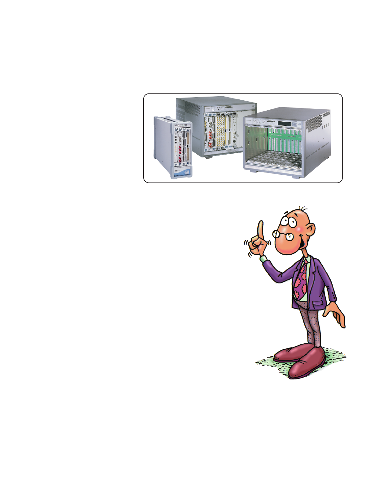
VXIbus: The Test and Measurement Standard
Instrument-On-A-Card Systems
Page 4
GPIB and VMEbus:
The Foundation for VXIbus
The Consortium members
recognized Agilent Technologies’
GPIB (IEEE-488) and VMEbus as
the two most popular standards
for instrumentation. They decided
to take the best from these
standards and add more features
to create the best possible IAC
standard.
What is GPIB?
In the early 1970’s, Agilent
Technologies invented an 8-bit
parallel interface- GPIB. It allowed
rack and stack instruments to
communicate with each other
and with a host computer. In
1975, GPIB was adopted by the
IEEE as standard IEEE-488.
Today, it is the leading interface
used in automated test systems
built on individual instruments.
It is simple, f lexible, and used
by nearly all instrument
manufacturers.
GPIB is a widespread standardit allows you to connect instruments
from several manufacturers to a
host computer (controller), and
thus build an automated, integrated
test system. Normally, you don’t
have to worry about how information
is passed between the devices.
Your only concern is the content
of the information, whether it be
ASCII or binary instructions to
an instrument, or ASCII or binary
results from an instrument.
A good way to think of GPIB
instruments is as electronic devices
that operate by themselves. They
have communication intelligence,
and may also perform sophisticated
data capture and analysis. An
example is a digital multimeter.
Using GPIB, you can send the
multimeter a sequence of ASCII
strings that instruct it to take a
burst of 1000 readings. You may
also send it commands telling it
to calculate statistical functions
like minimum, maximum, and
standard deviation on the readings.
Then you can bring only those
resulting values back to the
computer.
One limitation of GPIB has been
a maximum data transfer rate of
about 1 Mbyte per second. This is
usually not a problem, since most
applications are limited by the
speed of the measurement circuits,
or by the switch closure and
settling time required to route
signals. However, it can become a
problem with high-speed digitizing,
digital inputs/outputs, or if
large amounts of data must be
transferred from an instrument
to the computer for specialized
processing. Furthermore, the
GPIB protocol limits the transfer
speed to that of the slowest
device on the bus.
What is VMEbus?
While GPIB is the most popular
electronic instrument interface,
VMEbus is widely used in microcomputer systems. The VMEbus
specification was released in
August 1982, and approved by
IEEE and ANSI in 1987.
You can think of VMEbus as an
interface with two componentsmechanical and logical. The
mechanical portion specifies the
physical dimensions of plug-in
boards, backplanes, subracks, etc.
(The form factor of the plug-in
boards is commonly known as
the Eurocard format.) The logical
portion of the interface describes
how functional modules (in this
case, plug-in cards) communicate
with each other. A major objective
of VMEbus is to allow communication
between two devices without
disturbing the internal activities
of other devices in the system.
VMEbus systems can have
multiple microprocessors
on the same backplane.
4
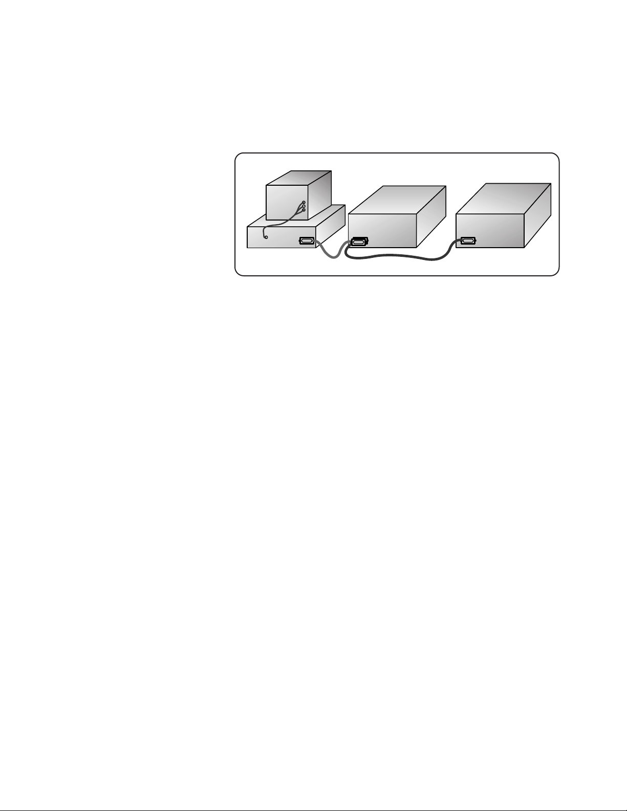
Figure 1. A GPIB System: Ease of Use, Ease of Integration
Page 5

One strength of VMEbus is that it
allows high-speed communication
between devices (which we
use interchangeably here with
“modules”). The specification
was originally intended for
microcomputer systems. As
instrument speeds increased
and printed circuit board sizes
decreased, interest grew in
bringing electronic instruments
into the system. However, this
brought out two shortcomings
of VMEbus: the electrical
environment, designed for digital
communication, is too “noisy”
for precise analog measurements,
and the programming needed for
high-speed communication has to
be done with low-level register
reads and writes.
VXIbus:
The Best of Both Worlds,
and More!
Members of the VXIbus Consortium
realized that for the VXIbus
standard to be successful, it must
answer two major challenges in
instrumentation: communication
speed and integration. The GPIB
and VMEbus specifications held
the answers to both these problems.
A third challenge solved by the
Consortium was to devise a welldefined environment in which
different vendors’ products can
operate together properly.
The result is the VXIbus (VMEbus
Extensions for Instrumentation )
Taking the Best from GPIB & VMEbus.
The VMEbus specification,
originally designed for microcomputers, has a great potential
for high-speed device-to-device
communication. This can increase
the throughput of your test system
considerably. And GPIB is well
known for its ease of integration,
which helps you to build your test
system faster. So the two main
challenges- speed and integrationwere answered. Although the
GPIB and VMEbus standards have
different bus communication styles,
VXIbus defines two different
devices to take advantage of
these styles.
Remember that GPIB instruments
are easy to use. You simply connect
the cable and program the instruments in whatever language they
require. In VXIbus systems, the
counterpart to GPIB instruments
are “Message-Based Devices.”
They are easy to integrate into a
system and communicate at a
high level using ASCII characters.
Like GPIB instruments, MessageBased Devices can contain
significant intelligence and
data processing capabilities.
Like instruments on a GPIB bus,
however, Message-Based RegisterBased Devices can be limited
when it comes to high-speed data
transfer.
The outstanding feature of
VMEbus devices is that they can
move data between themselves
very fast. The VXIbus specification
defines “Register-Based Devices”
as the analog to VMEbus devices.
These devices communicate at
a lower, more basic level than
Message-Based Devices and
so can attain greater transfer
speeds. Programming a RegisterBased Device involves writing to
and reading from individual
registers on the device.
5
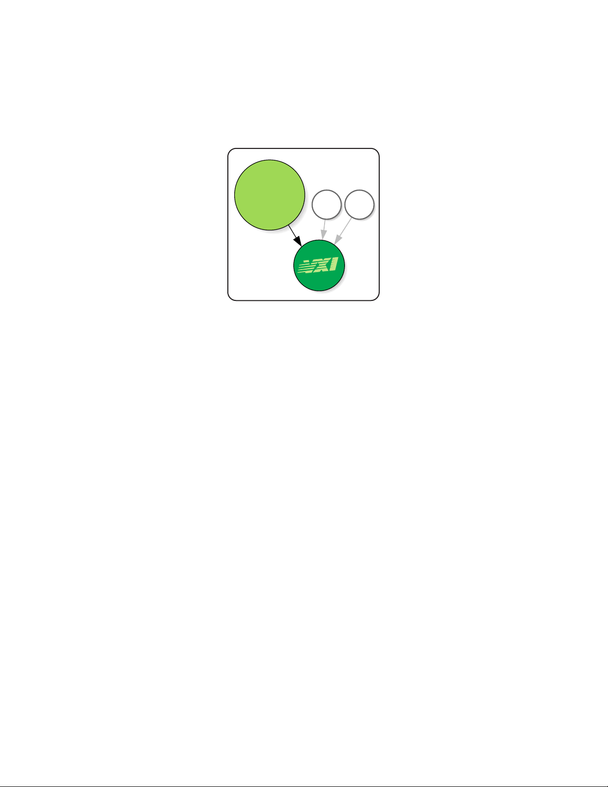
VXIbus: The Best of Both Worlds, and More!
VME
GPIB
Register-Based
Devices (Binary)
Message-Based
Devices (ASCII)
Easy
Fast
bus
Figure 2. A VMEbus System: Potential for High Speed And Multiple Processors
Figure 3. VXIbus: The Best of Two Worlds
Page 6
More Features of VXIbus Systems.
The VXIbus Consortium fully
defined the operating environment
for VXIbus modules. All VXIbus
mainframes must state how much
power and cooling they provide.
And all VXIbus modules must
state how much power and cooling
they require. Also, there are strict
limits on how much conducted
and radiated interference is
allowed between modules.
These parameters allow you
to configure a workable system
easily.
Two special functions must
be performed in every VXIbus
system. The first, Slot 0, takes
care of backplane management.
Slot 0 is a unique physical location
in every VXIbus mainframe. Signals
from this slot must include things
like clock sources, arbitration
for data movement across the
backplane, etc. The module that
goes into this slot must perform
these hardware functions in
addition to its normal functions.
If you’re familiar with VMEbus
systems, you probably recognize
that this is very similar to VME’s
“Slot 1 Device.” The Slot 0 device
relieves you of the burden of
managing data flow across the
backplane.
The second special function in
a VXIbus system is the Resource
Manager. The best way to think
of the Resource Manager is as a
computer program. This program
configures the modules for proper
operation whenever the system is
powered on or reset. This means
that you can build your test system
software from a known starting
point. The Resource Manager is
not involved with the VXIbus
system once normal operation
begins.
6
VMEGPIB
bus
• Instrumentation
Environment
• Slot 0 Functions
• Resource
Manager
Easy
Fast
Figure 4. VXIbus Additional Features
Page 7

With the rapid growth of computercontrolled instruments, Agilent
Technologies recognized the need
for a common instrumentation
language. Therefore, in the late
1980’s, Agilent Technologies
invented TMSL (Test and
Measurement Systems Language)
and offered to make it an open
standard. TMSL itself was based
on industry standards wherever
possible, including IEEE-488.2
and IEEE-754. In April 1990,
this standard was accepted
by the industry, and renamed
SCPI (Standard Commands for
Programmable Instrumentation).
You now have to learn only this
single instrument programming
language, regardless of whose
digital multimeter (or other
similar instrument) you purchase.
With this standardized programming
language for VXIbus instrumentation in place, you can reduce your
test system programming time!
SCPI is now managed by a
consortium of nine instrument
manufacturers. Today, there
are over a thousand instrument
products using SCPI. For more
about how SCPI works, see the
SCPI: More Details section of
this booklet.
7
SCPI: the Standardized Programming Language
Page 8

VXIbus was a significant
effort to standardize modular
instrumentation. It provided
an open environment where any
vendor’s modules would plug into
any VXI mainframe. Users could
expect the module to fit the slot
size and be adequately powered
and cooled. However, VXIbus
didn’t address the need to integrate
a system that was truly vendor
independent and easily usable.
Wouldn’t it be nice if there were
a common look and feel, or a
standard soft front panel for
given instrument types from
various vendors? Wouldn’t it be
great if you could develop your
application program on a PC and
execute it on a UNIX platform?
Or, what about instrument
drivers? An industry standard
set of drivers would eliminate
custom driver design issues.
Agilent Technologies is an active
member in the VXIplug&play
System Alliance to address
these challenges.
What is VXlplug&play?
VXIplug&play is a term indicating
conformance to a new set of
system-level standards, produced
by the VXIplug&play Systems
Alliance. Agilent Technologies
joined the VXIplug&play Alliance
in 1994 in support of the Alliance’s
charter: “to improve the effectiveness of VXI-based solutions
by increasing ease-of-use and
improving the interoperability
of multi-vendor VXI systems.” The
goal of the Alliance is to achieve
interoperability of mainframes,
computers, instruments, and
software through open, multivendor standards and practices.
The Alliance consists of vendors
actively involved with end-users
to produce instrumentation
systems that meet this goal.
Additionally, the Alliance is
open to all vendors and users
as a forum for working together
to make VXI technology easier
to use.
Thanks to the work of the Alliance,
VXIplug&play components
integrate easily. The new standards
apply to instrument drivers,
soft front panels, installation
packages, documentation,
technical support, application
development environments, as
well as many other areas for
instrument system integration.
As with the VXIbus standard,
revisions to VXIplug&play will
continue to reduce your dependence
on any single vendor and simplify
your job of system design and
implementation.
What does VXlplug&play offer?
VXIplug&play improves productivity,
portability, and interoperability
for both vendors and end-users.
• Productivity
Use soft front panels to operate
and evaluate instrument
operation within minutes.
• Portability
Communicate with instruments
via any controller/computer
interface supported by the
VISA I/O library.
• Interoperability
Develop application programs
portable across computer
platforms and I/0 interfaces.
Add new programs without
having to rewrite existing ones.
With vendors and end-users
working together, the real needs
of system integration continue
to be analyzed, defined, and
implemented. For more on the
VXIplug&play standard, see the
VXIplug&play: More Details
section of this booklet.
8
VXIplug&play: The NEW Standard for Test and Measurement
Page 9

The VXIbus, SCPI, and
VXIplug&play standards can
improve your test system’s speed
and flexibility, lower your product
“life cycle” cost, protect your
investment, and provide a choice
of vendors’ products that will
work together in your test system.
Open Standards
VXIbus, SCPI, and VXIplug&play
are truly open standards. So far,
over 200 different manufacturers
have received identification codes
from the VXIbus Consortium, and
hundreds of different instruments
are available. This multi-vendor
environment ensures that your
investment in VXIbus products
will be protected long into the
future. If one manufacturer’s
instrument becomes obsolete, a
replacement should be available
from another. Also, there will be
many “niche” manufacturers
willing to provide specialty
modules- just as in the computer
industry.
Because of the open standards,
instrument manufacturers can
provide VXI products with the
benefits of standardized architecture,
instrument programming language,
and I/0 communication. The
backplane pinouts and communication techniques are already
defined for you. Power and
cooling capabilities are completely
specified. Also, electrical interference limits have been set, so
you know your module will have a
“quiet” environment. The VXIbus
specification defines all of these,
and takes care of the hardware
specifications for any VXI system.
The VXIplug&play System
Alliance completes the standardization process with specifications
for the operating system or
“framework,” instrument drivers,
and I/0 software. VXIbus and
VXIplug&play, working together,
give you all the tools and guidelines
needed to successfully design a
custom VXI-compatible module
for a unique function, build a new
VXI test system, or upgrade your
existing system.
9
What Do VXIbus, SCPI, and VXIplug&play Mean to you?
Page 10

Higher Test System Throughput
Increased test system throughput
gives you a great competitive edge
by lowering your testing and
manufacturing costs. The VXIbus
backplane has a theoretical data
transfer limit of 40 Mbytes per
second. Normally, the backplane
will not be a bottleneck for your
data transfer. The not-so-obvious
advantage of the VXIbus is its
potential for distributed intelligence,
which leads to increased system
throughput. Because of its VMEbus
background, VXIbus can deal
with multiple microprocessors
on the backplane existing within
a shared memory architecture.
Arbitrating data transfers on
the backplane allows for a higher
data bandwidth than any single
device in the system can achieve.
Multiple levels of priority allow
critical processes to interrupt and
use resources only when they’re
required.
How can this help you? Let’s say
you have an embedded computer
that’s transferring a large block of
readings from a digitizer into the
computer’s memory over the data
bus. Simultaneously, another
instrument like a counter might
be using the data bus to send a
value to the controller every few
milliseconds. At the same
time, another intelligent
device might be monitoring
several channels of voltage
and internally performing
limit checks. If a condition
goes out of limit, this device
could request the data bus at a
higher priority than the other
devices, and send only
the failure data to the
computer for immediate
action. Together, these
multiple devices, with
their different priorities,
can more efficiently fill
the data bus. This makes
for higher overall system
throughput.
10
Figure 5. Different Priorities, Maximum Throughput
1 - Transfer Data Blocks: priority low
2 - Update from Counter: priority medium
3 - Service Alarm Condition: priority high
Total Backplane Utilization
500 ms
100 ms
25 ms
1 - Transfer Data Blocks: priority low
500 ms
2 - Update from Counter: priority medium
3 - Service Alarm Condition: priority high
Total Backplane Utilization
25 ms
100 ms
Page 11

True Upgrade Path
Another great feature of the
VXIbus is a true migration or
upgrade path. This allows you to
use your current hardware and
software in future test systems.
Suppose your current application
is fairly simple: scan 15 channels
of voltage, measure the frequency
of two signals, and provide lowlevel power for a current loop.
This application could be easily
and inexpensively done by a system
based on small VXIbus modules.
Your testing needs may expand
in the future so that you’ll need
more high-performance instruments
such as a high-speed digitizer or
signal generator. These instruments
may only be available as larger and
more complex VXIbus modules. But
all your smaller VXIbus modules
will easily fit right into the new,
larger system! Also, VMEbus devices
that you’re currently using, or
plan to use, can be integrated
into a VXlbus system. Your
imagination is the only limit on
the size and complexity of your
system.
11
Figure 6. VXIbus: A True Upgrade Path
FuturePresent
Page 12

Easy Integration
with Rack and Stack
VXIbus and VXIplug&play
systems can coexist perfectly with
GPIB test systems. You can use
the resources from both without
being limited to one type of system.
In fact, many of your test systems
probably will be a mix of VXIbus
and non-VXI instruments. For
example, a test system may need
VXIbus to solve a throughput
bottleneck, and also a very high
accuracy measurement from a
network analyzer that is available
only as a standalone instrument.
Another common scenario might
be a VXIbus mainframe full of
instruments controlled by a
computer. The computer might be
embedded in the VXIbus mainframe
or external to it. At the same
time, this computer could easily
control several large programmable
power supplies via GPIB, and
perhaps monitor transducers
or data links via RS-232.
Both GPIB and non-VXI instruments
can be programmed exactly like
VXIplug&play instruments, by
adapting VXIplug&play instrument
driver technology and using SCPI
commands with either the VISA
I/0 Library or Agilent SICL
(Standard Instrument Control
Library).
Smaller Test Systems
Probably the most obvious
advantage of VXIbus systems is
the significant downsizing of test
systems. Much of the downsizing
results from using common power
supplies and eliminating front
panels. This benefit has been very
important to military users due to
their extremely large test systems,
and continues to grow in the
commercial world as devices
increase in electronic content
and complexity.
Access to Switching Modules
Many people are introduced to
VXI because of their need for
signal routing (switching). Almost
every test application requires
some sort of signal routing, and
VXI offers many more choices
than traditional rack and stack.
As more instruments become
available, the importance of VXI
in testing continues to grow.
12
Figure 7. Mix and Match with VXIbus and Rack & Stack
1. 2345 mV
Page 13

Long-Term Software Protection
VXIbus is an excellent solution
to the problem of hardware
compatibility- i.e., protecting
your hardware investment. But
software compatibility, software
development productivity, and
protecting your investment in
software are equally important
issues. In a lot of applications,
the cost of test system software
is actually greater than the cost
of the hardware!
Development of the VXIbus specifications increased awareness of
software incompatibility issues.
SCPI (Standard Commands for
Programmable Instrumentation)
can help you protect your software
investment with one standardized
programming language for VXIbus
instrumentation. For more
information, see the SCPI:
More Details section of this
booklet.
Multi-Vendor Interoperability
VXIplug&play emerged not only
to address software issues, but
also to define standards at a
complete system level. Successfully
integrating a multi-vendor VXI
system requires hardware working
together at the electrical and
mechanical level. The software
used to control the hardware
must also work together. In large,
complex test systems, determining
the “framework” or platform and
then finding components that
work together may be an integrator’s
greatest challenge. VXIplug&play
becomes an excellent solution for
integrating your VXI system into
a successful multi-vendor
environment.
With the VXIplug&play concept,
you designate a standard system
“framework” or platform based on
the system software you intend to
use (i.e., Microsoft® Windows®
3.1/95/98/Me/NT®/2000, or
HP-UX*). By using the framework
designation when you choose the
rest of your system components,
your VXIplug&play compliant
components will be easy to use
and easy to integrate into your
test system. No longer should the
preference for a particular software
or hardware component need
to lock you out of a system or
platform. Another benefit of
VXIplug&play is its portability
between the Windows and HP-UX
environments. This means that
your application written on HP-UX
can run under Windows with
a simple recompile of the code.
VXIplug&play gives you even
more flexibility in meeting your
test system needs in the multivendor environment.
13
* HP-UX is Hewlett-Packard’s implementation of UNIX.
Microsoft®, Windows®, Windows NT®, are registered
trademarks of Microsoft Corporation.
Page 14

In this chapter, we’ll give you
more detailed information about
VXIbus systems. This should answer
some common questions you may
have about VXIbus, and help you
“speak VXI” if you wish to
pursue further information.
The appendix of this
booklet has a list of
additional reading
materials.
Instrumentation Environment
The VXIbus is an open standard
that many manufacturers are
now using to develop a wide
variety of products. This
means the specification
must provide a well-defined
environment to guarantee
proper system operation.
To define an environment for
a variety of high-performance
instruments, the specification
addresses several important
issues in physical and electrical
compatibility.
Module Sizes
One requirement for physical
compatibility is the size of plug-in
modules. The VMEbus standard
defined two small module sizes.
They’re known as A-Size and BSize modules in VXIbus. These
modules are fairly compact; it’s
difficult to fit multi-functional
analog instruments onto them.
So the VXIbus Consortium
extended the VMEbus specification
for module sizes- it defined two
larger modules, C- and D-Size.
These four module sizes allow you
to make a number of price and
performance tradeoffs so you
can optimize your test system.
14
The VXIbus Standard: More Details
Figure 8. Different sized modules for many
applications
B
A
C
D
3.9 x 6.3 in
(10 x 16 cm)
9.2 x 13.4 in
(23 x 34 cm)
9.2 x 6.3 in
(23 x 16 cm)
14,4 x 13.4 in
(36 x 34 cm)
Page 15

The most common card sizes are
B- and C-Size. For any system,
PC-board space costs money.
The B-Size format gives you an
excellent tradeoff in cost and
complexity, and is very useful for
simpler, lower-cost instruments.
Instruments that make a good fit
for B-Size modules include relay
multiplexers, some voltmeters
and counters, and small numbers
of digital-to-analog converters.
C-Size is a good size for more
complex instruments requiring
extra space for sophisticated
circuitry or computation hardware.
Since A- and B-Sizes came from
the VMEbus, they retain the
module-to-module spacing of
0.8 inches (2 cm) specified by
VMEbus. Because C-Size is defined
by VXIbus, it uses a larger spacing
of 1.2 inches (3 cm). This gives
C-Size modules better shielding
from electrical interference, and
therefore better measurement
sensitivity and accuracy. Some
examples of instruments that
fit the C-Size format are highperformance multimeters, function
generators, high-speed digitizers,
and high point-count switches.
A-Size cards are too small for
precision instruments, given
current technologies. Still, they
are a good size for communication
interfaces to the non-VXIbus
world. The D-Size format is useful
in specialized applications, but it
does result in significantly higher
cost and increased rack space. As
a result, almost all manufacturers
are using multiple C-Size slots for
complex instruments instead of
putting them onto D-Size
modules.
Connectors and Buses
Closely related to module sizes
are the backplane connectors,
shown in Figure 9. All modules
must have at least one 96-pin
connector, known as P1. All the
pins on P1 are completely defined
by the VMEbus specification.
These definitions are maintained
in VXIbus. P1 contains all the
necessary lines for 16-bit data
transfer, handshaking, bus
arbitration, and interrupt
support.
It’s possible to add the optional
P2 connector on B-Size and larger
modules. This will expand the
data transfer bus and provide a
local bus for high-speed moduleto-module communication. On
D-size cards, you can add another
optional connector, P3, which
adds resources for specialized
instrumentation. When combined
with multiple module sizes, this
range of connectors allows you
to optimize your test system with
various price and performance
tradeoffs.
15
Agilent 34401A DMM and its VXIbus C-Size equivalent, the Agilent E1412A
Figure 9. VXIbus modules and connectors
B
A
C
D
• 16 bit Data Transfer Bus
• Arbitration Bus
• Prioritized Interrupt Bus
P 1
• Increase width of Data Transfer Bus
• 12-line Local Bus
• TTL & ECL Trigger Buses
• 10 MHz Clock Bus
• Power Distribution Bus
P 2 (optional)
• Increase width of Local Bus
• Increase width of ECL Trigger Bus
• 100 MHz Clock Bus
• ECL Star Bus
• Expand Power Distribution Bus
P 3 (optional)
P 1
P 2
P 3
Page 16

Power, Cooling, and Interference
The second major issue of
compatibility addressed by
the VXIbus specification is the
mainframe environment. VXIbus
product vendors need to know
exactly what type of environment
their module will be used in, so
they can design, test, and specify
it properly. This means you can
have great confidence that VXIbus
systems- including those comprised
of different vendors’ moduleswill function properly.
All VXIbus mainframes must
specify how much steady-state
and dynamic current they provide
at different voltage levels. Also,
mainframes must specify how
much cooling, on a per-slot basis,
they provide. VXIbus plug-in
modules must provide corresponding information about their own
requirements.
Plug-in modules must also specify
both high-frequency emission
and susceptibility. The VXIbus
specification sets strict limits
for the amount of interference a
device may emit. Conversely, the
device’s operation must not be
affected by neighboring modules
operating within interference
limits. These limits and tests
apply to both radiated and
conducted signals.
VXIbus Devices and
Communication
What Are Devices?
In this booklet, you’ll notice
the term “device” used often.
The simplest way to think
of a device is as a plug-in
module, or card. In VXIbus
systems, every device must
have a unique address
from 0 to 255, called its
Logical Address. This
distinguishes it from other
devices in the system.
Every VXIbus device is
granted 64 absolute
addresses on the backplane.
You can think of this as 64
bytes of RAM on the device that
can be addressed and accessed
by other devices in the system.
This little block of memory serves
two main purposes- it contains
information about the device
and its communication capabilities,
and it’s also the location where
all required communication
with the device takes place.
The device’s Logical Address
determines the address of this
“information and communication
memory” within a VXIbus system.
This 64-byte chunk of dedicated
memory contains the device’s
“Configuration Registers” and
“Communication Registers.”
The VXIbus specification defines
four types of devices- RegisterBased, Message-Based, Memory,
and Extended. Memory devices
are just specialized RegisterBased Devices that are optimized
to hold and move large amounts
of data. Extended Devices are
currently reserved, and provide
a growth path for new types of
devices in the future.
16
Figure 10. VXIbus device registers.
Memory address is determined by VXIbus logical
address.
Status and Control
Device Type
Identification Register
Device
Dependent
Registers
16 bits
32 words
(64 bytes)
Memory address is
determined by VXIbus
Logical Address
Page 17

Register-Based Devices
In the first section of this booklet,
we said that VXIbus Register-Based
Devices communicate much like
VMEbus Devices. This means that
they’re programmed at a low level
using binary information. The
obvious advantage of this is speedRegister-Based Devices communicate
literally at the level of direct
hardware manipulation. This
high-speed communication can
lead to much greater test system
throughput.
All types of devices in a VXIbus
system must have some sort of
communication interface to the
VXIbus backplane.
One advantage of Register-Based
Devices is that this interface is
very simple, and thus small and
low in cost.
The Register-Based Device is ideal
for simple cards such as switches,
multiplexers, basic DACs, etc.
There’s little reason to put a
large, expensive communication
interface on these devices. The
register-based interface is also a
good choice for devices that may
need to move large amounts of
information across the VXIbus
backplane at very high speedsfor example, high-speed digitizers
and high-speed digital I/O cards.
You might think Register-Based
Devices are limited to being very
simple devices. However, this
is not the case. For example, a
register-based digital multimeter
may communicate with other
devices using low-level binary
commands, but it could also have
an internal microprocessor for
sophisticated measurement
control and self-diagnostics.
A lot of people like Register-Based
modules because of their low
cost, but don’t want to have to
program them with low-level
binary commands. VXIbus
answers this concern with a
concept called Commanders
and Servants (not a video game).
A device that contains the
intelligence to operate a RegisterBased Device can be configured
as a Commander to that RegisterBased Device. You send high-level
ASCII commands to the
Commander, it interprets them,
and then sends the necessary
binary information to the
Register-Based Servant. In this
mode, you program RegisterBased Devices exactly as if they
are Message-Based Devices.
Figure 12 shows the options
available for programming
Register-Based Devices.
17
Figure 11. Register-Based communication Figure 12. Paths for register-based communication
Easy (ASCII)
Fast (binary)
Register-
Based
Device
Register-
Based
Device
Register-
Based
Device
Register-
Based
Device
You
"Commander"
for
Register-
Based
Devices
Register-Based Device
Instrument
Control
Registers
Binary
Information
V
X
I
B
a
c
k
p
l
a
n
e
Page 18

Message-Based Devices
Message-Based Devices, in
contrast to Register-Based
Devices, communicate at a
very high level using ASCII
characters. A good analogy for
these devices is standalone GPIB
instruments. Message-Based Devices
are very easy to integrate into
VXIbus systems. This is especially
important in systems comprised
of modules supplied by different
vendors.
Message-Based Devices
communicate with each other
with a well-defined set of rules
known as “Word Serial Protocol.”
This asynchronous protocol
defines the handshaking
necessary to move commands
and data between devices.
One advantage of Word Serial
Protocol is that it hides compatibility
concerns from you, the user. That’s
why Message-Based Devices are
easy to integrate into a system.
To program them, you simply
send and retrieve high-level ASCII
characters. The characters you
send must be in the device’s
specific language, but you don’t
have to worry about modulespecific registers, binary reading
and writing, etc.
Two tradeoffs are required to
have this ease of use. First, the
communication interface required
to implement the Word Serial
Protocol is complex. This means
it takes up more “real estate”
on the circuit board than the
communication interface of a
Register-Based Device. Hence, a
Message-Based Device will always
cost more than an equivalent
Register-Based Device. Also,
because of the space committed
to communication rather than
measurement circuitry, MessageBased instruments will generally
be on C-Size or larger modules.
Second, the communication speed
between devices is lower. It’s
roughly equal to that of GPIB.
However, most sophisticated
devices will have on-board data
processing, so they may only
need to pass a final result from
the device to the controller. An
example of this is an oscilloscope
that digitizes a waveform and
then automatically measures rise
time. Only the rise time is passed
from the instrument, not all the
digitized readings.
18
Figure 13. Message-Based communication
Message-Based Device
ASCII
characters
V
X
I
B
a
c
k
p
l
a
n
e
Local
Intelligence
(microprocessor)
Page 19

More on Communication
The ability to communicate
between devices, the VXIbus
backplane, and computers is an
integral part of any VXIbus test
system. We’ve already defined the
two primary types of devices Register and Message - and how
they are set up for communication.
How can we improve data transfer,
or make measurements for tests
requiring transfers of large amounts
of data? How can we continue to
grow test systems and keep cost
low? With new developments in
external interfaces and both
external and embedded computers,
the rules are changing and more
options are being created for
answering these questions.
GPIB & LAN
As noted earlier, one limitation of
GPIB is its maximum data transfer
rate: about 1 Mbyte per second. If
GPIB speeds meet your application
needs, you can add the flexibility
and long-distance capabilities
of LAN to your test system
architecture. For instance, a LAN/
GP-IB Gateway, with measurement
server software, allows test
systems, whose components have
GPIB interfaces, to be controlled
by a computer via a thin or twisted
pair LAN. It is particularly useful
when the device under test is in
a protective or environmental
chamber some distance away
from the computer; engineers
can follow the test run’s progress
from a workstation at their desks.
You can also control multiple
GPIB test stations with one
computer by connecting each
test station to the LAN through
a GPIB/LAN Gateway. Another
advantage is the ability to create
measurement servers on the
network. This allows you to use
a measurement server to collect
test data and analyze it from
multiple locations.
External Interfaces
There are three basic choices for
interfacing between the VXIbus
backplane and your computer.
The most common is the popular
GPIB (IEEE-488) interface. A
GPIB Command Module resides
in slot 0 of the VXIbus system,
providing the required Resource
Manager and Slot 0 functions,
and acting as a GPIB-to-VXIbus
interface. This interfacing choice
easily allows you to combine your
VXIbus system and other GPIB
instruments on one computer
interface.
As the computer industry evolves
and creates new industry-standard
interfaces, VXIbus vendors are
taking advantage of these interfaces.
FireWire (IEEE-1394) is a low cost
interface that offers the ability to
move data at much faster rates
than GPIB. Compared to GPIB’s
theoretical limit of 1 Mbyte/sec,
FireWire has an upper limit of
50 Mbytes/sec. For applications
requiring the transfer of large
blocks of data, such as uploading
sequences of digitized waveforms,
FireWire is a very attractive
solution. In a manner similar to
GPIB, a FireWire Command
Module resides in slot 0 of the
VXIbus system, providing the
required Resource Manager and
Slot 0 functions, and acting as a
FireWire-to-VXIbus interface.
Since FireWire is a recognized
standard within the computer
industry, it is built into increasing
numbers of PCs as a standard
feature. FireWire interfaces are
also available to plug into PCs as
PCI cards. You can also easily
use both FireWire and GPIB
interface cards in your PC to
communicate with all your test
system resources, no matter
what kind of interface they use.
Another proprietary interface,
called MXIbus, has been developed
for VXIbus systems. With this
scheme, a MXIbus module plugs
into slot 0 of the VXIbus mainframe
and connects to the MXIbus
interface card in the external
computer. MXIbus provides the
speed and throughput of direct
memory-mapped access to the
VXI backplane. Due to its
proprietary nature and its design
that directly extends the VXIbus
backplane, MXIbus is higher in
cost than the industry-standard
alternatives of GPIB or FireWire.
With these advances in external
interfaces, VXIbus vendors
continue to push the limits for
faster and more configurable
communication tools.
19
Page 20

Embedded vs. External Computers
In addition to a rich choice of
interfaces between an external
computer and the VXIbus
backplane, you can also put your
computer directly on the VXIbus
backplane and inside the VXIbus
mainframe. Whether you choose
an embedded or external computer
will depend on your test system
needs. To select the best computer,
consider several factors: operating
system, throughput, ease of use,
physical size, configuration
flexibility, and cost.
For example, if your application
requires the greatest possible
throughput, a VXI embedded
PA-RISC computer using HP-UX the 9000 Series 700 -may best fit
your needs. Using this computer
in conjunction with VXI devices
that use high-speed register-level
communication gives you
maximum throughput.
When space is at a premium in
your test system set-up, embedded
computers are extremely valuable.
Embedded computers integrate
high functionality into small
modules for use in C-Size VXI
mainframes. Embedding the
computer in the VXI chassis
allows direct computer access
of other VXI devices, system
memory, and triggers as though
they were part of the computer
hardware. You get the highest
speed performance and computer
access to VXI devices while still
conserving space. An embedded
computer also allows you enclose
and secure your computer in the
same enclosure as your VXIbus
system.
With external computers, you
have a huge choice of PCs and
Unix workstations. You can
choose the combination of cost
and performance that best meets
the needs of your application.
An external computer allows
you to reap the benefits of the
fast-paced, changing technology
of the computer industry. You
can take advantage of continuous
improvements in price and
performance, and can upgrade
your computing power and
performance as your test system
requires. An external computer
requires the use of an interface to
connect to the VXIbus backplane.
If you need easy access to your
computer as you develop a test
application and cost is a primary
concern, an external computer PC-based or UNIX-based - may
better fit your needs. With an
external computer, you can cycle
the VXIbus mainframe power
without having to reboot an
embedded computer’s operating
system. If you have custom VXI
modules as part of your test
system, this can be very
important during application
development.
20
SYSTEM PRICE
SYSTEM I/O PERFORMANCE
GPIB
FireWire
MXIbus
Embedded
Computer
Page 21

SCPI: More Details
The cost of software for a test
system is often greater than the
cost of the hardware. In the late
1980’s, Agilent Technologies
invented and offered to make TMSL
(Test and Measurement Systems
Language) an open standard.
In April 1990, this standard
was accepted, and renamed
SCPI (Standard Commands for
Programmable Instrumentation).
SCPI complements the VXIbus
and VXIplug&play specifications,
helping you protect your investment
by using an industry-accepted
standard.
SCPI differs from earlier instrument
languages in that the commands
describe the signal you’re trying
to measure, not the instrument
you’re using to measure it. This
means programs written with
SCPI are more readable and
intuitive. You spend less time
learning about your instruments,
and more time solving your
application problems. This feature,
known as “horizontal compatibility,”
means that the same SCPI
commands apply to many
different types of instruments.
For example, the
“TRIGGER:IMMEDIATE”
command can be used with a
multimeter, oscilloscope, or any
other instrument with trigger
capability.
SCPI is also designed to be
extensible, allowing it to grow
as instrument capabilities grow.
Suppose that in the future you
buy a multimeter with more
features than your current
unit. Its basic functions will be
programmed exactly like the old
unit. This “vertical compatibility”
results in lower support costs,
obsolescence protection, and
an upgrade path. Headers,
mnemonics, and parameter
formats are standardized as well.
All Agilent Technologies VXIbus
products are programmed with
SCPI commands. You learn just
one programming language that,
in turn, increases your programming
efficiency and reduces the time
you spend on development. It also
ensures that your investment in
instrument control software is
protected.
21
OUTPUT@Dmm;“*RST” ! Reset all the
OUTPUT@Scope;“*RST” ! test system
OUTPUT@Counter;“*RST” ! instruments.
OUTPUT@Scope;“MEASURE:VOLTAGE:RISETIME?” ! Use oscilloscope to
ENTER@Scope;Risetime ! measure wave form risetime.
OUTPUT@Dmm;“MEASURE:VOLTAGE:DC?” ! Use DMM to accurately
ENTER@Dmm;Dc_level ! measure final signal level
OUTPUT@Counter;“MEASURE:FREQUENCY?” ! Use counter to measure
ENTER@Counter;Frequency ! freq of another signal
Figure 14. SCPI’s horizontal compatibility
Page 22

Making all the pieces fit together
is a big challenge for any system
integrator or engineer. If you
have ever done this, you will
be amazed at the
benefits that
VXIplug&play
brings to the
Test and
Measurement
industry.
VXIplug&play
compliant
systems provide
the mechanisms
for you to build
systems that
meet your specific
application needs,
while removing concerns about
software interoperability. The
VXIplug&play Systems Alliance
has achieved this by defining and
implementing requirements for
the entire test system- including
software, I/O communication,
drivers, installation packages,
computers and interfaces.
How does
VXlplug&play Work?
To understand how VXIplug&playcompliant components work
together, you must understand
each of the different pieces.
Of course, it begins with you
and your application. Then, you
choose your system framework.
Figure 15 is a simple display of
these pieces.
Frameworks
The VXIplug&play Systems
Alliance has defined several
“frameworks” based on established
industry-standard operating
systems. Specifically, a framework
relates to a particular operating
system (for example, Windows
3.1/95/98/Me/NT/2000, HP-UX,
GWIN, and others), and specifies
the requirements for instruments,
controllers, interfaces, mainframes,
and software packages that
comply with that system.
To make the example in Figure 15
work, the specification assigns a
framework designation to each
different piece of the system.
What does all this mean to you,
the test engineer or integrator?
Once you choose the framework
based on the system software
that meets the needs of your
unique test application, then the
framework designation is all you
need to know when choosing the
rest of your system components.
An Alliance specification defines
each VXIplug&play framework,
with detailed requirements for
all system pieces – from top to
bottom.
22
VXIplug&play: More Details
Page 23

For example, say you’ve chosen
Windows 95 as your system
framework. You will need to select
a PC, interface, VXI mainframe,
and VXI instruments that are
WIN 95 Framework-compatible.
Manufacturers of these system
components have already identified
which are VXIplug&play. One of
the instruments you may need is
an Agilent E1412A Digital Multimeter.
Because of VXIplug&play,
you will automatically receive an
installation disk or CD with the
appropriate library files (i.e., .dll),
MS WIN help files, knowledge
base file, and an executable soft
front panel file. (For more detail
on these features, keep reading. )
The VXIplug&play Specification
requires the manufacturer to
supply all of this support material
with this (and every) instrument
driver.
Instrument Drivers
One of the most exciting developments from the Alliance is standard
instrument drivers. The instrument drivers take care of the lowlevel details of I/0 communication.
As a test system developer, you
no longer need to deal with lowlevel I/0 protocols! As defined by
the Alliance, VXIplug&play
instrument drivers include the
following features:
C function library files
C function library files contain a
dynamic link library (.dll or .sl),
ANSI C source code (.c, .h), and
function panel file (.fp). It uses
the VISA I/0 Library for all I/0
functions. With these tools, you
have high-level, easy to use C
functions for your application.
Interactive soft front panel
executable program
A soft front panel is a graphical
user interface for an instrument.
However, soft front panels do not
generate code and are not for use
in a program. You use the soft
front panel when the instrument
is first integrated into the system.
You can verify your instrument
communications, or use it as a
learning tool to teach instrument
control and capability concepts.
Many test system users like this
feature because it is quick and
easy to determine if the instrument
is ready for use.
This tool is specifically useful
for system integration and for
incoming inspection tasks. It is
also an integral part in making
your system easier to use.
23
Figure 16. A VXIplug&play soft front panel
Agilent VEE,
NI's LabView and
LabWindows\CVI
Functional Panel
VXI
plug&play
-compliant
Instrument Drivers
Agilent's VISA or NI VISA
• Delivered with your instrument
• Downloaded to you controller
• Communicates low-level I/O details via VISA
Other
Applications
e.g.,
Visual Basic/C
Interface Hardware
(GPIB, FireWire, MXIbus)
YOUR
APPLICATION
Contains VXI
plug&play
function calls
Agilent I/O Libraries, including VISA I/O
Library, is provided with your interface or
embedded computer, and links your
application to your VXI instrument.
Figure 15. A VXIplug&play-compliant system
YOUR
APPLICATION
Contains VXIplug&play function calls
Agilent VEE,
NI's LabView and
LabWindows\CVI
Functional Panel
VXI
plug&play
Instrument Drivers
• Delivered with your instrument
• Downloaded to you controller
• Communicates low-level I/O details via VISA
Agilent's VISA or NI VISA
Interface Hardware
(GPIB, FireWire, MXIbus)
Other
Applications
e.g.,
Visual Basic/C
-compliant
Page 24

Knowledge base file
A knowledge base file describes
all specifications for an instrument
as an ASCII file. These specifications
include mechanical, electrical,
and environmental information.
This is useful when used as a
system integration tool for multivendor systems.
Help file
A help file provides help
information for the C function
library, programming examples,
instrument overview, and the
soft front panel. You can copy or
paste the programming examples
directly into your application
program. This can greatly reduce
your development time.
VXIplug&play requires delivery
of the instrument driver with
your instrument. All you need to
do is load it onto your computer.
VISA I/0 Library
Without a common I/0 library,
interoperability of system
components is not possible.
Therefore, a standard I/0 library
became a primary goal of the
VXIplug&play Alliance. I/0
software takes care of the
communication over a physical
connection, and is the foundation
on which other standards are
built. To move away from existing
proprietary systems, languages,
and I/0, the library needed to
be independent of instrument,
interface, operating system,
language, or networking
mechanisms.
The VXIplug&play Alliance calls
the new standard I/0 library
“VISA”- Virtual Instrument
Software Architecture. VISA
provides a single foundation for
multi-vendor instrumentation
software. The development of
VISA provides access to new
capabilities as technology changes,
as well as maintaining a migration
path for existing systems. VISA
offers all of these as a single,
easy-to-use set of I/0 control
functions very similar to existing
I/0 libraries, such as Agilent’s
SICL.
VISA provides a set of core
functions- Location and Life
Cycle Control (open, close),
Events (enable, disable), and
Message-Based Control (write,
read, print), just to name a few.
Each of these functions applies to
all instruments. This means you
can use VISA’s open ( or viOpen)
function call for any device in
your test system.
VISA’s development and
standardization offer you even
more benefits. With fewer functions
to learn, you reduce the time spent
learning a new tool. Since it is
similar to existing I/O libraries,
you probably already have the
knowledge to begin development
of your application. Another great
benefit of VISA is its portability
between frameworks. Your
applications written on HP-UX
can run under Windows with
just a simple recompile of the
code. You are no longer platformdependent! VISA gives you
system-level confidence and
removes your dependency on a
single vendor’s I/O strategy.
24
Page 25

GPIB Instruments
GPIB
FireWire
GPIB
VXI Embedded Computer
External Computer/Interface
COMPUTER/INTERFACE
INSTRUMENTS
INTERCONNECT & WIRING
A VXIbus system can be thought
of as a collection of tasks to be
performed. Most of these tasks
will be specific to your application,
while some of them must be done
in every VXIbus system.
Yesterday, a discussion about the
“typical” VXIbus system would
discuss Resource Manager, Slot 0
Functions, GPIB, and Command
Modules. Perhaps you could
configure one or more CPUs
into the system to store and process
information. Even though Resource
Manager and Slot 0 Functions are
unique to VXIbus systems, today
we look at test systems differently.
Never before has the system
integrator been able to benefit
from the large selection of open
test system components! Now
available from Agilent Technologies
and a growing list of instrument
manufacturers is standard,off-
the-shelf test system hardware
and software: PCs or UNIX
computers (standalone or
VXI format); IEEE-488,
IEEE-1394, and MXIbus
interfaces; and VXIbus
instrumentation. VXI is a
completely open environment
for both hardware and instrument
control software. You specify
the VXIplug&play framework
based on the operating system,
and then select the rest of your
system components based on
that framework. If you already
have a test system set-up, you can
continue with your GPIB solution
and begin moving to higherperformance VXI solutions
as your needs grow.
25
Putting It All Together
Page 26

By now, you can see that VXIbus
and VXIplug&play standards
provide a well-defined hardware
and software environment, in
which modules from many different
manufacturers can work together.
How is Agilent Technologies
involved in this process?
In the past, Agilent participated
in the standardization process
by providing technology and
developments of our own to
everyone in the industry- GPIB
(lEEE-488) and SCPI. Thus,
Agilent was one of the first
instrument manufacturers to
realize the need for industry
standards. Today, Agilent’s
commitment to these and to
new standards continues to
grow with the needs of the
Test and Measurement industry.
Agilent VEE, Agilent’s Visual
Engineering Environment, is
VXIplug&play-compliant for
Agilent instruments, as well as
for non-Agilent products. How?
Agilent VEE can access and load
any instrument driver written to
the VXIplug&play standard. The
instrument driver then provides
a procedural interface to the
instrument for programmatic
control. Agilent VEE uses a
graphical user interface to make
it easy for you to develop the
code necessary for controlling
your instruments.
Agilent also provides soft front
panels and robust help files with
all instrument drivers to help you
understand and operate your
instruments quickly. Since most
complex test systems are not
completely populated with VXI,
Agilent is a leader in providing a
common driver strategy for both
VXI and non-VXI (GPIB)
instruments.
Even though VXIbus and
VXIplug&play define both
the hardware and software
environments, these standards
still do not address everything
you’ll need for a total system
solution. Agilent offers an
instrument family that has a
consistent “look and feel,” provides
many cost and performance
alternatives, is easy to integrate,
and allows you to get your test
system operating quickly.
26
What has Agilent Technologies Done to Improve Upon VXI Technology?
Page 27

During its first decade, VXIbus
has spawned an unexpected
level of industry cooperation in
achieving a truly open modular
instrumentation architecture. It’s
easy to understand how industry
standards deliver benefits. One
only has to observe the success of
the PC, as thousands of computer
users switched to this open platform
so broadly supported by the
computer industry. The VXI
platform now brings the same
benefits to instrument users:
• Today, VXI is a stable, highly
standardized platform with
hundreds of products available,
making your investment secure.
As you combine hardware and
software from a variety of
vendors, you’re assured that
your system will work.
• VXI provides scalable, configurable
solutions that adapt to your
unique measurement situation
allowing you to trade-off cost
and performance. And VXI is
easily integrated into existing
or new rack and stack systems
for complete solutions that can
reduce your cost of test.
• VXI has spawned other open
standards, that help you save
development time, and protect
your system investments -for
instance, SCPI and VXIplug&play.
• VXI has influenced the
development of test software
programming languages, such
as Agilent VEE, that complement
and support the VXI environment
and allow an unprecedented
level of test software development productivity, saving time
and money.
With VXI technology rapidly
emerging as the industry
standard in all facets of
instrumentation, you can expect
manufacturers to continue to
provide even greater productivity
gains, as well as to reduce test
system costs. Agilent Technologies
will continue to be the leading
manufacturer in VXI technology
and products, and will continue
to drive industry standards that
truly benefit instrumentation
users.
27
Summary
Page 28

By internet, phone, or fax, get assistance
with all your test & measurement needs
Online assistance:
www.agilent.com/find/assist
Phone or Fax
United States:
(tel) 1 800 452 4844
Canada:
(tel) 1 877 894 4414
(fax) (905) 282 6495
Europe:
(tel) (31 20) 547 2323
(fax) (31 20) 547 2390
Japan:
(tel) (81) 426 56 7832
(fax) (81) 426 56 7840
Latin America:
(tel) (305) 269 7500
(fax) (305) 269 7599
Australia:
(tel) 1 800 629 485
(fax) (61 3) 9210 5947
New Zealand:
(tel) 0 800 738 378
(fax) 64 4 495 8950
Asia Pacific:
(tel) (852) 3197 7777
(fax) (852) 2506 9284
Product specifications and descriptions in this
document subject to change without notice.
Copyright © 2001 Agilent Technologies
Printed in the USA April 16, 2001
5988-2372EN
Agilent Technologies’ Test and Measurement
Support, Services, and Assistance
Agilent Technologies aims to maximize the
value you receive, while minimizing your risk
and problems. We strive to ensure that you
get the test and measurement capabilities you
paid for and obtain the support you need. Our
extensive support resources and services can
help you choose the right Agilent products for
your applications and apply them successfully.
Every instrument and system we sell has a
global warranty. Support is available for at
least five years beyond the production life of
the product. Two concepts underlie Agilent’s
overall support policy: “Our Promise” and
“Your Advantage.”
Our Promise
Our Promise means your Agilent test and
measurement equipment will meet its
advertised performance and functionality.
When you are choosing new equipment, we
will help you with product information, including
realistic performance specifications and
practical recommendations from experienced
test engineers. When you use Agilent
equipment, we can verify that it works properly,
help with product operation, and provide basic
measurement assistance for the use of
specified capabilities, at no extra cost upon
request. Many self-help tools are available.
Your Advantage
Your Advantage means that Agilent offers
a wide range of additional expert test and
measurement services, which you can
purchase according to your unique technical
and business needs. Solve problems efficiently
and gain a competitive edge by contracting
with us for calibration, extra-cost upgrades,
out-of-warranty repairs, and on-site education
and training, as well as design, system
integration, project management, and other
professional engineering services. Experienced
Agilent engineers and technicians worldwide
can help you maximize your productivity,
optimize the return on investment of your
Agilent instruments and systems, and obtain
dependable measurement accuracy for the life
of those products.
 Loading...