

Page 1

Superior signal integrity
Deep application analysis
Better insight
Agilent Infiniium
DSA/DSO90000A Series
Data Sheet
13 GHz bandwidth
40 GSa/s sampling rate
1 Gpts deep memory
3-stage sequence trigger
Page 2

Infiniium 90000A Series: Highlights
Superior signal integrity, deep application analysis, better insight
The Agilent Infiniium 90000A oscilloscope helps us capture large amounts of data and
process that data record in a much shorter time. This improves our development time
and shortens our time to market.
Bill Simms, Mixed Signal Design Validation manager, NVIDIA Corp
The last time you purchased a
high-performance real-time scope,
what trade-offs did you make? To
analyze and debug next-generation,
high-speed digital and RF designs,
you wanted the lowest noise floor, the
longest capture time, and the deepest
analysis capabilities. But you couldn't
find that all in one instrument – so you
compromised.
This time, you won't have to make
trade-offs. The all-new Infiniium
DSA/DSO90000A Series scopes
deliver superior signal integrity,
barrier-breaking memory depth,
and unmatched signal analysis and
debugging. So you enjoy better insight
than ever into high-speed digital and
RF designs.
Each scope in the Infiniium 90000A
Series scopes gives you all the
industry-leading capabilities you're
looking for. You want the industry's
lowest noise floor? Superior signal
integrity is a must to make highly
accurate, repeatable measurements
you feel confident in. The 90000A
Series scopes deliver: The 12 GHz
model, for example, provides an
industry-leading low noise floor of
435 µVrms at 5 mV per division. The
longest capture time? These are the
first high-performance scopes that
can acquire one billion samples
(1 Gpts). That means you can capture
a long 25 ms record of your signal
at 40 GSa/s.
You want the deepest analysis
capabilities? Debug and
characterization speeds along with
the new InfiniiScan Plus event
identification system, based on a
world-class hardware trigger system
that can detect glitches as low as
125 ps. And if you work on high-speed
video interfaces, such as HDMI
(high-definition multimedia interface)
and DisplayPort, you'll appreciate the
standard analog HDTV triggers.
Do you just need to capture a signal
of interest? Take advantage of the
industry's only three-stage sequence
trigger system. Combining A-B
hardware triggers with InfiniiScan
software to enable triggering flexible
enough to handle almost any debug
situation.
You also get other features that make
your job quicker and easier. Trigger
with the TIE (time interval error) jitter
value lets you investigate complex
jitter phenomena with a simultaneous
analysis and debugging tool that
displays eye pattern analysis, protocol
decoding information, jitter trend,
and histogram analysis all on one
screen, for a time-correlated view. And
high-speed offload via gigabit Ethernet
and a USB 2.0 device port transfers
data at industry-leading rates for rapid
offline analysis.
Welcome to the world of
ultra-performance. With the new
Infiniium DSA/DSO90000A Series
scopes, you finally get the tool you've
always wanted for next-generation
high-speed digital and RF designs.
• Low noise: Industry’s lowest noise
floor for both oscilloscopes and
probes
• 1 Gpts: Industry-leading MegaZoom
ultra-deep memory at 40 GSa/s on
all four channels
• Advanced triggering: Industry’s
only three-stage sequence
triggering with InfiniiScan Plus
trigger system
• 13 GHz and 40 GSa/s: Up to 13 GHz
bandwidth, up to 40 GSa/s sample
rate on four channels
• 22 MSa/s: Industry-leading data
transfer rate from the oscilloscope
• 122,000 measurements per sec:
Amazing measurement update
throughput
• –55 to 150 °C: Industry’s only
environmental chamber probing
solution
• 2.5 µs: Industry-leading segment
memory speed
• Flatness: Industry’s flattest
frequency response
• Upgrade: Industry’s only
bandwidth-upgradeable series from
2.5 GHz to 13 GHz
• Share: Industry’s only server-based
oscilloscope application software
license solution
• Applications: Industry’s largest
selection of application software
packages
• 12.1 inch screen: Large display size
with XGA resolution
2
www.agilent.com/find/90000Ademo
Page 3

Infiniium 90000A Series: Design Concept
Superior signal integrity, deep application analysis, better insight
The design concept
Evaluate signal integrity. Validate
compliance. Debug and analyze designs.
When we developed the Infiniium 90000A
Series, we took a close look at the key
tasks that engineers of high-speed digital
and RF designs perform. Then we created a
series of scopes that could help you manage
each of these tasks quickly and easily.
We tapped the expertise we've acquired
during 50+ years spent advancing scope
technology. So you can finally work with an
ultra-performance scope that keeps up with
you and your leading-edge designs.
Signal
Debug
Integrity
AnalysisCompliance
Infiniium multi-chip module isolates EMI.
To enable our scopes to operate at high
frequencies with minimal electromagnetic
interference (EMI), we relied on our expertise
in radio frequency (RF) technology. Instead
of implementing each component of a
digital circuit in a separate circuit block,
we created a multi-chip module that uses a
“Faraday Cage” to isolate EMI. The result?
High-bandwidth scopes with the lowest noise
floor in the industry.
Infiniium hardware sequence
trigger chip. This chip enables
the new world of three stage
triggering available on the
90000A Series scopes.
www.agilent.com/find/90000Ademo
3
Page 4

Infiniium 90000A Series: Selection Guide
Superior signal integrity, deep application analysis, better insight
90000A Series Infiniium oscilloscopes
Real-time
Model
91304A 13 GHz 40 GSa/s on 4 ch 10 Mpts on 4 ch 1 Gpts on 4 ch 3.37 mVrms
91204A 12 GHz 40 GSa/s on 4 ch 10 Mpts on 4 ch 1 Gpts on 4 ch 2.80 mVrms
90804A 8 GHz 40 GSa/s on 4 ch 10 Mpts on 4 ch 1 Gpts on 4 ch 2.22 mVrms
90604A 6 GHz 20 GSa/s on 4 ch 10 Mpts on 4 ch 1 Gpts on 4 ch 1.92 mVrms
90404A 4 GHz 20 GSa/s on 4 ch 10 Mpts on 4 ch 1 Gpts on 4 ch 1.56 mVrms
90254A 2.5 GHz 20 GSa/s on 4 ch 10 Mpts on 4 ch 1 Gpts on 4 ch 1.27 mVrms
bandwidth on 4 ch
Maximum sampling
rate on 4 ch Standard memory Maximum memory
Noise floor at
100 mV/div
How much time span can I capture?
10 Mpts of
Sampling rate
40 GSa/s 250 μs 500 μs 1.25 ms 2.5 ms 5.0 ms 12.5 ms 25.0 ms
20 GSa/s 500 μs 1 ms 2.5 ms 5.0 ms 10.0 ms 25.0 ms 50.0 ms
memory
20 Mpts of
memory
50 Mpts of
memory
100 Mpts of
memory
200 Mpts of
memory
500 Mpts of
memory
1 Gpts of
memory
Note: time span capture = memory depth x 1/sampling rate
®
Acquiring 25 ms of PCI EXPRESS
chance of capturing your signal of interest.
Gen 2 data at 40 GS/s using 1 Gpts of memory will provide you the highest
4
www.agilent.com/find/90000Ademo
Page 5

Infiniium 90000A Series: Selection Guide
Superior signal integrity, deep application analysis, better insight
How much bandwidth do I need to measure a given rise/fall time accurately?
Rise/fall time (20 - 80%) 3% accuracy 10% accuracy 20% accuracy
100 ps 5.6 GHz 4.8 GHz 4.0 GHz
75 ps 7.5 GHz 6.4 GHz 5.3 GHz
60 ps 9.3 GHz 8.0 GHz 6.7 GHz
50 ps 11.2 GHz 9.6 GHz 8.0 GHz
40 ps 14.0 GHz 12.0 GHz 10.0 GHz
30 ps 18.7 GHz 16.0 GHz 13.3 GHz
Notes: Maximum signal frequency content = 0.4/rise time (20 - 80%)
Scope bandwidth required = 1.4 x maximum signal frequency for 3% measurement accuracy
Scope bandwidth required = 1.2 x maximum signal frequency for 10% measurement accuracy
Scope bandwidth required = 1.0 x maximum signal frequency for 20% measurement accuracy
Choose the probes you need for your application
InfiniiMax II Series probe amplifiers
Model Bandwidth Description
1169A 12 GHz (spec) 13 GHz (typical) InfiniiMax II probe amplifier – order one or more probe heads
1168A 10 GHz InfiniiMax II probe amplifier – order one or more probe heads
InfiniiMax II probe amplifier specifications: Dynamic range = 3.3 V, DC offset range = ± 16 V, maximum voltage = ± 30 V
InfiniiMax I Series probe amplifiers
Model Bandwidth Description
1134A 7 GHz InfiniiMax I probe amplifier – order one or more probe heads
1132A 5 GHz InfiniiMax I probe amplifier – order one or more probe heads
1131A 3.5 GHz InfiniiMax I probe amplifier – order one or more probe heads
1130A 1.5 GHz InfiniiMax I probe amplifier – order one or more probe heads
InfiniiMax I probe amplifier specifications: Dynamic range = 5 V, DC offset range = ± 12 V, maximum voltage = ± 30 V
www.agilent.com/find/90000Ademo
5
Page 6

Infiniium 90000A Series: Selection Guide
Superior signal integrity, deep application analysis, better insight
InfiniiMax II Series probe heads
InfiniiMax II Series probe heads are recommended for 1169A/68A probe amplifiers. The typical performance when used with a
DSA/DSO91304A is shown below.
Differential measurement
Probe head Model number
High-Bandwidth differential SMA N5380A 12.5 GHz 12.5 GHz
High-Bandwidth differential
solder-in
High-Bandwidth differential
browser
High-Bandwidth differential
replaceable ZIF solder-in*
High-Bandwidth differential
replaceable long wire ZIF solder-in*
N5381A 13 GHz, 0.21 pF, 50 kΩ 13 GHz, 0.35 pF, 25 kΩ
N5382A 13 GHz, 0.21 pF, 50 kΩ 13 GHz, 0.35 pF, 25 kΩ
N5425A/N5426A (requires both
N5425A and N5426A)
N5451A (requires N5425A) 9 GHz at 7 mm wire 5 GHz at 11 mm wire
(Bandwidth, input C, input R)
13 GHz, 0.33 pF, 50 kΩ 13 GHz, 0.53 pF, 25 kΩ
Single-ended measurement
(Bandwidth, input C,input R)
InfiniiMax I Series probe heads (can be used with 1169A/68A probe amplifiers with limitations)
Probe head Model number
High-bandwidth differential
replaceable ZIF solder-in*
N5425A/N5426A (requires both
N5425A and N5426A)
Differential measurement
(Bandwidth, input C, input R)
12 GHz, 0.33 pF, 50 kΩ 12 GHz, 0.53 pF, 25 kΩ
Single-ended measurement
(Bandwidth, input C, input R)
High-bandwidth differential
replaceable long-wire ZIF
solder-in*
Differential solder-in
(Higher loading, high-frequency
response variation)
Differential socket
(Higher loading)
Differential browser – wide span E2675A 6 GHz, 0.32 pF, 50 kΩ 6 GHz, 0.57 pF, 25 kΩ
Differential SMA E2695A 8 GHz 8 GHz
Single-ended solder-in (must
bandlimit input to ≤ 6 GHz)
Single-ended browser E2676A N/A 6 GHz, 0.67 pF, 25 kΩ
Differential kit E2669A (includes E2675A, E2677A and E2678A)
Single-ended kit E2668A (includes E2676A, E2679A and E2678A)
High-impedance adapter E2697A (includes 500 MHz passive probe)
* Number of insertions supported: 20 cycles (50 cycles (typical))
6
www.agilent.com/find/90000Ademo
N5451A (requires N5425A) 9 GHz at 7 mm wire 5 GHz at 11 mm wire
E2677A 12 GHz, 0.27 pF, 50 kΩ 12 GHz, 0.44 pF, 25 kΩ
E2678A 12 GHz, 0.34 pF, 50 kΩ 12 GHz, 0.56 pF, 25 kΩ
E2679A N/A 6 GHz, 0.50 pF, 25 kΩ
Page 7

Infiniium 90000A Series: Selection Guide
Superior signal integrity, deep application analysis, better insight
Recommended bandwidth and Infiniium 90000A Series support for popular bus standards
Serial data analysis (E2688A)
Jitter
1
analysis
Bus standard Bit rate
Recommended
bandwidth
Ethernet 250 Mbs 2 GHz Yes Yes N/A Yes N5392A N5395B
USB 2.0 up to 480 Mbs 2 GHz Yes Yes N/A Yes N5416A E2649A
DDR1 up to 400 MTs 2 GHz Yes N/A N/A No U7233A No
DDR2 up to 800 MTs 4 GHz Yes N/A N/A No N5413A W2631A
DDR3 up to 1.6 GTs 6 GHz Yes N/A N/A No U7231A W2635A
SATA 1.5 Gbps 1.5 Gbps 6 GHz Yes Yes Yes Yes N5411A COMAX
SAS 150 1.5 Gbps 6 GHz Yes Yes Yes Yes N5412A N5421A
Fibre Channel 2.125 Gbps 4 GHz Yes Yes Yes Yes N5410A No
HDMI 1.3a/b up to 3.4 Gbps 8 GHz Yes Yes Yes Yes N5399A N1080A
2
SW clock
recovery
8b/10b
decode
Mask
testing
Compliance
testing Test fixtures
4
3
3
W2641A
®
PCI-SIG
PCMCIA.org
DisplayPort 1.1 2.7 Gbps 8 GHz Yes Yes Yes Yes U7232A
PCI EXPRESS I 2.5 Gbps 6 GHz Yes Yes Yes Yes N5393B
ExpressCard 2.5 Gbps 6 GHz Yes Yes Yes Yes N5393B
InfiniBand 2.5 Gbps 6 GHz Yes Yes Yes Yes No Fujikura
Advanced TCA 2.5 Gbps 6 GHz Yes Yes Yes Yes No No
4
SATA 3 Gbps 3.0 Gbps 10 GHz Yes Yes Yes Yes N5411A
SAS 300 3.0 Gbps 10 GHz Yes Yes Yes Yes N5412A
COMAX
4
N5421A
10G Ethernet 3.125 Gbps 8 GHz Yes Yes N/A Yes No No
XAUI 3.125 Gbps 8 GHz Yes Yes Yes Yes N5431A No
Serial Rapid IO up to 3.125 Gbps 8 GHz Yes Yes Yes Yes N5431A No
FireWire up to 3.2 Gbps 8 GHz Yes Yes N/A N/A Yes - QP Quantum Para.
4
4
No
N4235A/36/38A
Fibre Channel 4.25 Gbps 10 GHz Yes Yes Yes Yes N5410A
FBD I up to 4.8 Gbps 12 GHz Yes Yes N/A Yes N5409A
PCI EXPRESS II 5.0 Gbps 13 GHz Yes Yes Yes Yes N5393B No
SATA 6 Gbps 6.0 Gbps 13 GHz Yes Yes Yes No No No
SAS 600 6.0 Gbps 13 GHz Yes Yes Yes No No No
Fibre Channel 8.5 Gbps 13 GHz Yes Yes Yes No No No
1 Recommended bandwidth is derived from a combination of data rate and edge speed
2 Jitter analysis solutions: EZJIT (E2681A), EZJIT Plus (N5400A), oscilloscope tools (E2690B)
3 Requires E2688A serial data analysis
4 Requires E2688A serial data analysis and N5400A EZJIT Plus jitter analysis
www.agilent.com/find/90000Ademo
7
Page 8

Infiniium 90000A Series
Superior signal integrity, deep application analysis, better insight
40-GSa/s sample rate on each of
four channels provides ultra-low noise
13 GHz full real-time bandwidth of the
oscilloscope simultaneously.
See your signal more clearly with
a 12.1-inch XGA (1024 x 768)
high-resolution touch screen color
display. Infiniium’s bright TFT display.
Identify anomalies easily with
a 256-level intensity-graded or
color-graded-persistence display that
provides a three dimensional view of
your signals.
Live indicator shows when the scope
is running a long operation.
Remote access through 10/100/1000
BaseT LAN interface with
Web-enabled connectivity using
ultra-responsive Ultra VNC.
GPIB over LAN provides remote
measurement. Optional Infiniium
application remote program interface
allows application/compliance
software automation. LXI class C
compliant.
Capture your longest signal with
up to 25 ms data using 1 G point of
acquisition at 40 GSa/s.
Removable hard disk drive option is
available for added data security.
Optional USB external DVD-RW drive
allows you to install your favorite
third-party software conveniently and
can be used to back up your critical
measurement data.
8
www.agilent.com/find/90000Ademo
Install third-party software packages on Windows XP Pro operating system
such as Excel, LabVIEW, Agilent VEE, MATLAB®, anti-virus software, and more,
to perform customized processing and automation of your oscilloscope or to make
the scope compliant to the network environment of your company.
Page 9

Infiniium Series oscilloscope: Award-winning Infiniium scopes have received
ten industry awards to date, including EDN’s “Innovation of the Year” award
(twice) and T&M World’s “Best in Test.” Agilent is committed to breaking new
ground and providing tools that bring unique value to our customers.
Simply press the horizontal delay knob
to set the delay value to zero. A zoom
button provides quick access to two
screen zoom mode.
10-MHz reference clock can be input
to or output from the scope to allow
precise timebase synchronization with
RF instruments or logic analyzers.
Dedicated single acquisition button
provide better control to capture an
unique event.
Customizable Multipurpose key gives
you any five automated measurements
with a push of a button. You can
also configure this key to execute a
script, print/save screen shots, save
waveforms, or load a favorite setup.
Measure section including a toggling
marker button and a dedicated marker
knob provides quick access to your
marker control.
Quick access to fine/vernier control
by pressing the horizontal and vertical
sensitivity knobs.
Starting with an 18-GHz, BNC-compatible connector, an ultra-low noise floor
front end design using Faraday cage technology ensures high signal integrity in
its signal path.
AutoProbe interface completely configures your scope for use with the InfiniiMax
probing system and previous-generation Agilent active probes.
Increase your productivity with
a familiar Infiniium graphical
user interface, like your favorite
drag-and-drop measurement icons.
Infiniium’s analog-like front panel has
a full set of controls color coded to the
waveforms and measurements, making
your tasks simple.
Three front panel USB 2.0 host ports
will suite perfectly for your USB
keyboard, mouse, and USB memory
drive connection for saving setup files,
data files, and screen shots.
Four more USB 2.0 host ports and a
USB 2.0 device port on the back panel.
Perfect for extra connectivity including
an optical drive. A USB 2.0 device
port lets you control the scope and
transfer data via a USB 2.0 480-Mbpts
connection.
www.agilent.com/find/90000Ademo
9
Page 10

InfiniiMax II: The World’s best high-speed probing system
just keeps getting better
InfiniiMax offers you the highest
performance available for measuring
differential and single-ended signals,
with flexible connectivity solutions for
today’s high-density ICs and circuit
boards.
InfiniiMax probes have fully
characterized performance for all
of their various probe heads. This
includes:
• Swept frequency response plot
• Common mode rejection versus
frequency plot
• Impedance versus frequency plot
• Time-domain probe loading plot
• Time-domain probe tracking plot
One-year standard warranty on active
probes and a variety of Agilent support
options to choose from.
Controlled impedance transmission
lines in every probe head deliver full
performance versus the performance
limitations introduced by traditional
wire accessories.
Probe interface software allows you
to save the calibration information
for up to 10 different probe heads per
channel and will automatically retrieve
calibration data for a probe amplifier as
it is attached to the scope.
E2677A 12-GHz solder-in differential probe
head can be attached to very-small-geometry
circuits for measuring both single-ended and
differential signals. External mini-coaxial
resistors facilitate wider span but have
increased high-frequency response
variation relative to N5381A.
E2679A 6-GHz extremely small
single-ended, solder-in probe
heads for probing even the
hardest-to-reach single-ended
signals.
N5381A 13-GHz high-bandwidth
solder-in differential probe head
provides maximum bandwidth and
minimizes capacitive loading to
≤ 210 fF. Variable spacing from
0.2 to 3.3 mm (8 to 130 mills).
E2677A
E2679A
N5381A
N5425A
High-input impedance active probes
minimize loading, support differential
measurements and DC offset, and can
compensate for cable loss.
Probe calibration software delivers the
most accurate probe measurements
and linear phase response and allows
various probe combinations to be
deskewed to the same reference time.
A flat frequency response over the
entire probe bandwidth eliminates the
distortion and frequency-dependent
loading effects that are present in
probes that have an in-band resonance.
10
www.agilent.com/find/90000Ademo
N5425A 13-GHz
high-bandwidth solder-in
differential ZIF probe head
and N5426A ZIF tip provides
maximum bandwidth with
industry’s first lead-free
solder-in probe solution in an
economical replaceable tip
form factor.
N5451A 9-GHz/5-GHz
long-wire ZIF tip provides
high-bandwidth economical
replaceable solder-in tip with
extra reach (9 GHz with 7 mm
and 5 GHz with 11 mm wire).
N5426A
N5451A
E2695A
E2695A
8-GHz
differential SMA
probe head
allows you to
connect two SMA
cables to make
a differential
measurement on
a single scope
channel.
Page 11

Six different InfiniiMax probe amplifiers from 1.5 GHz to 13 GHz are available for
matching your probing solution to your performance and budget requirements.
The 1168/69A InfiniiMax II amplifiers offer the highest bandwidth and the lowest
noise floors. The 1134/32/31/30A offer a more cost effective solution and wider
dynamic range.
N5382A 13-GHz high-bandwidth differential browser
N5382A
provides maximum bandwidth for hand-held or probe
holder use. Variable spacing from 0.2 to 3.3 mm (8 to
130 mills).
E2675A 6-GHz differential browser is the best choice
for general-purpose trouble shooting of differential
or single-ended signals with z-axis compliance and
variable spacing from 0.25 - 5.80 mm (10 - 230 mills).
E2675A
N5450A
N5450A InfiniiMax extreme
temperature extension
cable provides extra
reach into environmental
chambers.
N5380A
E2676A 6-GHz single-ended browser is the best
choice for general-purpose probing of single-ended
E2676A
signals when small size of the probe head is the
primary consideration.
E2678A
E2678A 12-GHz differential socket probe head
can be used to measure either differential or
single-ended signals via a plug-on socket connection.
N5380A 13-GHz high-bandwidth differential SMA probe head
provides maximum bandwidth for SMA-fixtured differential pairs.
Probe performance plots available
The InfiniiMax II probe manuals contain an extensive set of
performance plots (bandwidth, probe tracking, CMRR, step
response, impedance) for various probe configurations.
See the following Web site for this information
http://cp.literature.agilent.com/litweb/pdf/01169-97005.pdf
www.agilent.com/find/90000Ademo
11
Page 12
Deep Application Analysis
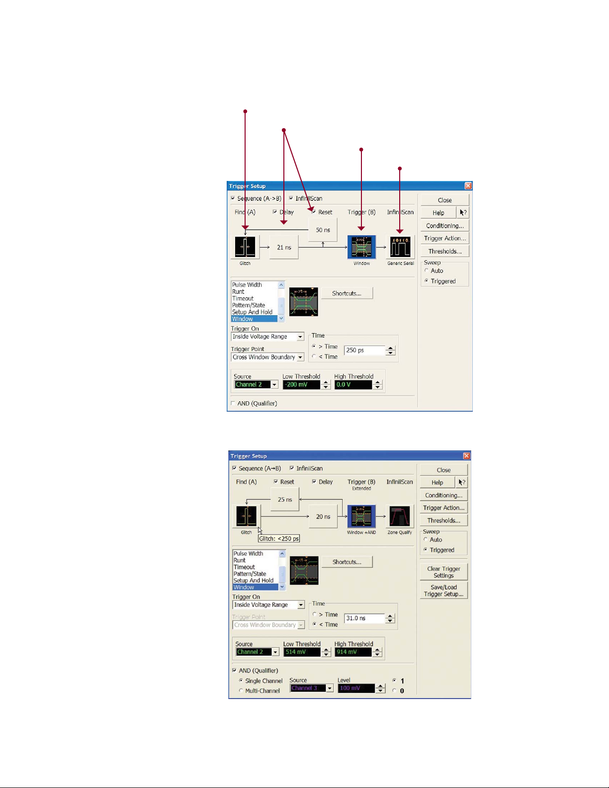
InfiniiScan Plus: Industry’s first three-stage sequence trigger system
One of the keys to a “deep application
analysis” is to have a superior
triggering system that combines the
stability of a hardware trigger and
the flexibility of a software trigger.
The InfiniiScan Plus trigger system
provides the world’s first three-stage
sequence trigger.*
Available hardware trigger selections
for first stage:
• Edge
• Edge transition
• Edge then edge
• Glitch
• Pulse width
• Pattern/state
• Runt
• Setup and hold
• Timeout
• Video including HDTV trigger,
(available only for first stage)
• Window
First stage: hardware trigger (Find event (A))
Delay and reset conditions
Second stage: hardware trigger (Find event (B))
Third stage: software trigger (InfiniiScan)
Available hardware trigger selections
for second stage:
• Edge
• Edge transition
• Glitch
• Pulse width
• Pattern/state
• Runt
• Setup and hold
• Timeout
• Window
Available software trigger selection
for third stage:
• Measurement
• Zone qualify
• Generic serial
• Non-monotonic edge
• Runt
InfiniiScan Plus trigger setup
InfiniiScan software trigger setup screen
12
www.agilent.com/find/90000Ademo
Page 13

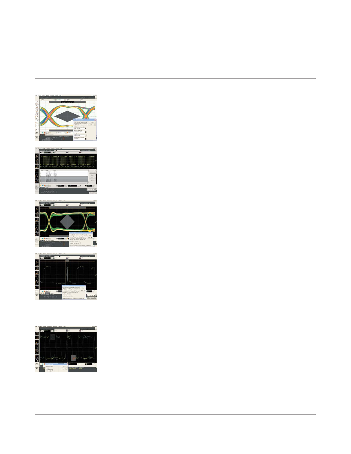
Deep Application Analysis
Advanced integrated analysis solution
This example shows troubleshooting
the eye pattern failure of PCI EXPRESS
compliance pattern. A serial data
analyzer will quickly analyze the eye
pattern, and if there is a violation, it
will unfold it for you to see. Once you
correlate the TIE jitter to a particular
eye pattern failure, the next step of the
debug/analysis is to set up the trigger
condition in order for the Infiniium
scope to trigger on a particular TIE
value.
PCI EXPRESS compliance test pattern
Real-time 8b10b decode
(PCI EXPRESS compliance pattern =
K28.5, D10.2, K28.5, D21.5)
Real-time time interval error (TIE) jitter
trend plotting revealed a large TIE jitter
associated with this eye failure.
Picture on the right shows the
InfiniiScan setup screen to trigger on a
TIE jitter more than 50 ps or less than
–10 ps. Infiniium Series is the first
oscilloscope that can trigger with a
measured TIE jitter value.
TIE jitter analysis for the
entire acquisition data
PCI EXPRESS eye pattern
violation mask unfold result
Navigation tool to search through each eye pattern
failures (example has eight failures). Could all
failures be related to this particular TIE jitter issue?
www.agilent.com/find/90000Ademo
13
Page 14

Deep Application Analysis
Advanced integrated analysis solution
5 Gbps PCI EXPRESS Gen 2 eye pattern. The ultra-low
noise floor of DSA91204A shows the true performance
of your device under test.
Making more than 5 million measurements in less than 1
minute using the “Measure All Edges” mode and long memory,
increases your confidence in the measurement statistics.
Consistently trigger on 200 ps single bit (one UI) of
PCI EXPRESS Gen 2 using industry-leading < 250 ps
glitch trigger.
Total jitter (Tj) analysis (Dj/Rj) for 5 Gbps PRBS signal
using N5400A EZJIT Plus. Deep memory makes it
possible to reveal a low-frequency-jitter components.
The “true” ease of use. Just draw boxes and the scope
will trigger. The industry’s only software event finder,
“InfiniiScan Event Identification Tool” will provide the
next level of ease-of-use for the scope triggering system.
14
www.agilent.com/find/90000Ademo
Certified Wireless USB compliance testing using
VSA (vector signal analysis software) and the
DSA91204A. VSA is used in the CWUSB compliance
test workshop.
Page 15

Infiniium 90000A Series Oscilloscopes
Performance characteristics
Vertical
Input channels Four
Analog bandwidth
, 10
(–3 dB)*
DSP enhanced bandwidth
Rise time/fall time
11
10 - 90%
20 - 80%
3
90254A 90404A 90604A 90804A 91204A 91304A
2.5 GHz 4 GHz 6 GHz 8 GHz 12 GHz 13 GHz
91304A: 13-GHz real-time, user-selectable DSP enhanced bandwidth
90254A 90404A 90604A 90804A 91204A 91304A
140 ps 105 ps 70 ps 54 ps 35 ps 32 ps
105 ps 79 ps 53 ps 38 ps 25 ps 23 ps
Input impedance 50 Ω, ± 3%
Sensitivity
1
1 mV/div to 1 V/div
Input coupling DC
Vertical resolution
2
Channel to channel isolation
(any two channels with
equal V/div settings)
8 bits, ≥ 12 bits with averaging
DC to 3 GHz: 90804A/91204A/91304A: 60 dB (≥ 1000:1)
90254A/90404A/90604A: 50 dB (≥ 316:1)
3 GHz to 8 GHz: 40 dB (≥ 100:1)
8 GHz to BW: 35 dB (≥ 56:1)
DC gain accuracy*
, 1
± 2% of full scale at full resolution channel scale (± 2.5% for 5mV/div)
Maximum input voltage* ± 5 V
Offset range Vertical sensitivity Available offset
0 mV/div to ≥ 40 mV/div ± 0.4 V
> 40 mV/div to ≥ 75 mV/div ± 0.9 V
> 75 mV/div to ≥ 130 mV/div ± 1.6 V
> 130 mV/div to ≥ 240 mV/div ± 3.0 V
> 240 mV/div ± 4.0 V
Offset accuracy*
, 1
≤ 3.5 V: ± (2% of channel offset + 1% of full scale) + 1 mV
> 3.5 V: ± (2% of channel offset + 1% of full scale)
Dynamic range ± 4 div from center screen
DC voltage measurement
accuracy*
, 1
Dual cursor: ± [(DC gain accuracy) + (resolution)]
Single cursor: ± [(DC gain accuracy) + (offset accuracy) + (resolution/2)]
RMS noise floor (scope only)
Volts/div
5 mV
10 mV
20 mV
50 mV
100 mV
200 mV
500 mV
1 V
* Denotes warranted specifications, all others are typical. Specifications are valid after a 30-minute warm-up period, and ±5 °C from annual calibration temperature.
1 Full scale is defined as 8 vertical divisions. Magnification is used below 5 mV/div. Below 5 mV/div, full-scale is defined as 40 mV. The major scale settings are 5 mV, 10 mV,
20 mV, 50 mV, 100 mV, 200 mV, 500 mV, 1 V.
2 Vertical resolution for 8 bits = 0.4% of full scale, for 12 bits = 0.024% of full scale.
3 13 GHz DSP enhanced bandwidth not applicable at 5 mV/div.
10 11.8 GHz analog bandwidth at 5 mV/div for DSO91304A and DSO91204A models.
11 Calculated from the bandwidth.
90254A 90404A 90604A 90804A 91204A 91304A
153 μV 199 μV 259 μV 322 μV 435 μV 467 μV
183 μV 232 μV 295 μV 358 μV 483 μV 536 μV
275 μV 342 μV 424 μV 498 μV 650 μV 758 μV
645 μV 799 μV 985 μV 1.15 mV 1.45 mV 1.73 mV
1.27 mV 1.56 mV 1.92 mV 2.22 mV 2.80 mV 3.37 mV
2.47 mV 3.03 mV 3.71 mV 4.28 mV 5.41 mV 6.58 mV
6.48 mV 8.00 mV 9.91 mV 11.5 mV 14.7 mV 17.4 mV
12.5 mV 15.6 mV 19.2 mV 22.3 mV 28.5 mV 34.1 mV
www.agilent.com/find/90000Ademo
15
Page 16

Infiniium 90000A Series Oscilloscopes
Performance characteristics
Vertical (continued)
RMS noise floor
(scope with probe)
Volts/div
20 mV
50 mV
100 mV
200 mV
500 mV
1 V
Horizontal
Main timebase range 5 ps/div to 20 s/div real-time, 5 ps/div to 500 ns/div equivalent-time
Main timebase delay range –200 s to 200 s real-time, –25 μs to 200 s equivalent-time
Zoom timebase range 1 ps/div to current main time scale setting
Channel deskew ± 25 μs range, 100 fs resolution
90254A 90404A 90604A 90804A 91204A 91304A
with 1131A with 1132A with 1134A with 1168A with 1169A with 1169A
3.2 mV 3.5 mV 4.0 mV 2.2 mV 2.5 mV 2.7 mV
3.3 mV 3.6 mV 4.0 mV 2.3 mV 2.8 mV 3.1 mV
3.4 mV 3.8 mV 4.3 mV 2.9 mV 3.5 mV 4.2 mV
4.0 mV 4.6 mV 5.3 mV 4.7 mV 5.9 mV 7.5 mV
7.1 mV 8.6 mV 10 mV 12 mV 15 mV 19 mV
13 mV 16 mV 19 mV 23 mV 28 mV 37 mV
Time scale accuracy* ± (0.4 + 0.5 * YrsSinceCal) ppm pk
Delta-time measurement
accuracy
Absolute,
averaging disabled
Absolute,
>- 256 averages
Standard deviation,
averaging disabled
Standard deviation,
>- 256 averages
Jitter measurement floor
Time interval error6c
Period jitter
6a, 6b, 7
6a, 6b
5.0 • Noise
(
√
SlewRate 2
0.35 • Noise
(
√
SlewRate 2
1.4 • Noise
(
√
SlewRate
0.1 • Noise
(
√
SlewRate
1.0 • Noise
(
√
SlewRate
1.4 • Noise
(
√
SlewRate
2
+ 20x10
)
2
+ 0.1x10
)
2
+ 0.6x10
)
2
+ 0.01x10
)
2
+ 0.3x10
)
2
+ 0.6x10
)
TimeScaleAccy • Reading
–24
+
–24
+
–24
sec
–24
sec
–24
sec
–24
sec
TimeScaleAccy • Reading
rms
rms
rms
rms
sec pk
sec pk
N-cycle, cycle-cycle jitter
16
www.agilent.com/find/90000Ademo
2.4 • Noise
(
√
SlewRate
2
+ 1.7x10
)
–24
sec
rms
Page 17

Infiniium 90000A Series Oscilloscopes
Performance characteristics
Acquisition
Maximum real-time sample rate 91304A/91204A/90804A: 40 GSa/s (4 channels simultaneously)
90604A/90404A/90254A: 20 GSa/s (4 channels simultaneously)
Memory depth per channel
Standard
Option 20M
Option 50M
Option 100
Option 200
Option 500
Option 01G
Maximum acquired time at highest
real-time resolution
Resolution
Standard
Option 20M
Option 50M
Option 100
Option 200
Option 500
Option 01G
10 Mpts on 4 channels
20 Mpts on 4 channels (standard on DSA models)
50 Mpts on 4 channels
100 Mpts on 4 channels
200 Mpts on 4 channels
500 Mpts on 4 channels
1 Gpts on 4 channels
91304A/91204A/90804A 90604A/90404A/90254A
25 ps (40 GSa/s) 50 ps (20 GSa/s)
0.25 ms 0.5 ms
0.5 ms 1.0 ms
1.25 ms 2.5 ms
2.5 ms 5.0 ms
5.0 ms 10.0 ms
12.5 ms 25.0 ms
25.0 ms 50.0 ms
Data transfer speed
Gigabit Ethernet
USB 2.0 hi-speed (device)
Sampling modes
Real-time
Real-time with averaging
Real-time with peak detect
Real-time with hi resolution
Equivalent-time
Segmented memory
Samples: 1 k 64 k 1 M 16 M 32 M 128 M
MSa/s (Word): 0.1 1.88 9.25 12.00 12.80 12.80
MSa/s (Byte): 0.11 1.88 12.60 19.70 20.30 22.00
Samples: 1 k 64 k 1 M 16 M 32 M 128 M
MSa/s (Word): 0.11 1.88 8.34 8.55 9.07 11.38
MSa/s (Byte): 0.11 1.88 11.60 14.40 14.90 18.10
Successive single-shot acquisitions
Selectable from 2 to 65534
91304A/91204A/90804A: 40 GSa/s
90604A/90404A/90254A: 20 GSa/s
Real-time boxcar averaging reduces random noise and increases resolution
Resolution: 100 fs
Full bandwidth on all 4 channels, 262,144 sample points maximum memory
Captures bursting signals at maximum sample rate without consuming memory during periods of
inactivity
Number of segments:
Up to 131,072 segments (depending on installed memory depth and model number)
Minimum intersegment time:
91304A / 91204A / 90804A: 2.7 μs
90604A / 90404A / 90254A: 2.5 μs
(the time between the end of the previous acquisition and the beginning of the next acquisition)
Maximum number of segments:
Sample rate 10 M 20 M 50 M 100 M 200 M 500 M 1 G
DSA/DSO91304, 91204, 90804 1024 2048 4096 8192 16384 32768 65536
DSA/DSO90604, 90404, 90254 2048 4096 8192 16384 32768 65536 131072
Filters
Sin(x)/x Interpolation On/off selectable FIR digital filter. Digital signal processing adds points between acquired data
points to enhance measurement accuracy and waveform display quality.
www.agilent.com/find/90000Ademo
17
Page 18

Infiniium 90000A Series Oscilloscopes
Performance characteristics
Hardware trigger
Sensitivity
Level range
Internal
Auxiliary
Sweep modes Auto, triggered, single
Display jitter (displayed trigger
jitter)
Trigger sources Channel 1, channel 2, channel 3, channel 4, aux, and line
Trigger modes
Edge
Edge transition
Edge then edge (time)
Edge then edge (event)
Glitch
Line
Pulse width
Runt
Timeout
Pattern/pulse range
State
Setup/hold
1
6a, 8
91304A/91204A/90804A: Internal low1: 2.0 div p-p 0 to 5 GHz
Internal high
90604A/90404A/90254A
Internal high
Auxiliary: DC to 100 MHz: 200 mV p-p into 50 Ω
100 MHz to 1 GHz: 500 mV p-p into 50 Ω
± 4 div from center screen or ± 4 Volts, whichever is smallest
± 5 V, also limit input signal to ± 5 V
90804A, 91204A, 91304A:
0.9 • Noise
(
√
SlewRate
90254A, 90404A, 90604A:
0.9 • Noise
(
√
SlewRate
Triggers on a specified slope (rising, falling or alternating between rising and falling) and voltage
level on any channel or auxiliary trigger.
Trigger on rising or falling edges that cross two voltage levels in > or < the amount of time specified.
Edge transition setting from 250 ps.
The trigger is qualified by an edge. After a specified time delay between 10 ns to 10 s, a rising or
falling edge on any one selected input will generate the trigger.
The trigger is qualified by an edge. After a specified delay between 1 to 16,000,000 rising or falling
edges, another rising or falling edge on any one selected input will generate the trigger.
Triggers on glitches narrower than the other pulses in your waveform by specifying a width less than
your narrowest pulse and a polarity. Triggers on glitches as narrow as 125 ps. Glitch range settings:
< 250 ps to < 10 s.
Triggers on the line voltage powering the oscilloscope.
Trigger on a pulse that is wider or narrower than the other pulses in your waveform by specifying a
pulse width and a polarity. Triggers on pulse widths as narrow as 125 ps. Pulse width range settings:
250 ps to 10 s. Trigger point can be “end of pulse” or “time out”.
Triggers on a pulse that crosses one threshold but fails to cross a second threshold before crossing
the first again. Can be time qualified with minimum setting of 250 ps.
Trigger when a channel stays high, low, or unchanged for too long. Timeout setting: from 250 ps to
10 s.
Triggers when a specified logical combination of the channels is entered, exited, present for a
specified period of time or is within a specified time range or times out. Each channel can have a
value of High (H), Low (L) or Don’t care (X).
Pattern trigger clocked by the rising, falling or alternating between rising and falling edge of one
channel.
Triggers on setup, hold, or setup and hold violations in your circuit. Requires a clock and data signal
on any two inputs (except aux or line) channels as trigger sources. Setup and/or hold time must
then be specified.
2
+ 0.3x10
)
2
+ 0.3x10
)
12
: Internal low1: 2.0 div p-p 0 to 5 GHz
–24
–24
sec
sec
1
: 0.3 div p-p 0 to 4 GHz, 1.0 div p-p 4 to 7.5 GHz
1
: 0.3 div p-p 0 to 3 GHz, 1.0 div p-p 3 to 5 GHz
rms
rms
18
www.agilent.com/find/90000Ademo
Page 19

Infiniium 90000A Series Oscilloscopes
Performance characteristics
Hardware trigger (continued)
Trigger modes (continued)
Window
Video
Trigger sequences Three stage trigger sequences including two-stage hardware (Find event (A) and Trigger event (B))
Trigger qualification AND qualifier Single or multiple channels may be logically qualified with any other trigger mode
Trigger holdoff range 100 ns to 10 s
Triggers on an event associated with a window defined by two-user adjustable thresholds. Event can
be window “entered,” “exited,” “inside (time qualified),” or “outside (time qualified)” voltage range.
Trigger point can be “cross window boundary” or “time out.” Time qualify range: from 250 ps to 10 s.
Triggers from negative sync composite video, field 1, field 2, or alternating fields for interlaced
systems, any field, specific line, or any line for interlaced or non-interlaced systems. Supports
NTSC, PAL-M (525/60), PAL, SECAM (625/50), EDTV (480p/60), EDTV (576p/50), HDTV (720p/60),
HDTV (720p/50), HDTV (1080i/60), HDTV (1080i/50), HDTV (1080p/60), HDTV (1080p/50), HDTV
(1080p/30), HDTV (1080p/25), HDTV (1080p/24), and user-defined formats.
and one-stage InfiniiScan software trigger. Supports all hardware trigger modes except “edge then
edge” and “video,” and all InfiniiScan software trigger modes. Supports “delay (by time)” and “reset
(by time or event)” between two hardware sequences. The minimum latency between “find event
(A)” and “trigger event (B)” is 3 ns.
Trigger actions Specify an action to occur and the frequency of the action when a trigger condition occurs. Actions
include e-mail on trigger and execute “multipurpose” user setting.
Trigger shortcuts Provides easy shortcuts to all trigger features
Software trigger (requires InfiniiScan event identification software – Option 009)
Trigger modes
Generic serial
Measurement limit
Non-monotonic edge
Runt
Zone qualify
Software triggers on NRZ-encoded data up to 8.0 Gbps, up to 80-bit pattern. Support multiple clock
data recovery methods including constant frequency, 1st-order PLL, 2nd-order PLL, explicit clock,
explicit 1st-order PLL, explicit 2nd-order PLL, Fibre Channel, FlexRay receiver, FlexRay transmitter
(requires E2688A except for the constant frequency clock data recovery mode).
Software triggers on the results of the measurement values. For example, when the “pulse width”
measurement is turned on, InfiniiScan measurement software trigger triggers on a glitch as narrow
as 75 ps. When the “time interval error (TIE)” is measured, InfiniiScan can trigger on a specific TIE
value.
Software triggers on the non-monotonic edge. The non-monotonic edge is specified by setting a
hysteresis value.
Software triggers on a pulse that crosses one threshold but fails to cross a second threshold before
crossing the first again. Unlike hardware runt trigger, InfiniiScan runt trigger can be further qualified
via a hysteresis value.
Software triggers on the user defined zones on screen. Zones can be specified as either “must
intersect” or “must not intersect.” Up to four zones can be defined.
Measurements and math
Maximum measurement update
rate
Measurement modes Standard, Measure All Edges mode
> 42,000 measurement/sec (one measurement turned on)
> 122,000 measurement/sec/measurement (five measurements turned on)
www.agilent.com/find/90000Ademo
19
Page 20

Infiniium 90000A Series Oscilloscopes
Performance characteristics
Measurements and math (continued)
Waveform measurements
Voltage
Time
Mixed
Frequency domain
Level qualification
Eye-diagram measurements Eye height, eye width, eye jitter, crossing percentage, Q factor, and duty-cycle distortion
Peak to peak, minimum, maximum, average, RMS, amplitude, base, top, overshoot, preshoot, upper,
middle, lower
Rise time, fall time, period, frequency, positive width, negative width, duty cycle, burst width, Tmin,
Tmax, Tvolt, setup time (requires Option 002 or 004, standard on DSA models), hold time (requires
Option 002 or 004, standard on DSA models), channel-to-channel delta time, channel-to-channel
phase
Area, slew rate
FFT frequency, FFT magnitude, FFT delta frequency, FFT delta magnitude
Any channels that are not involved in a measurement can be used to level-qualify all timing
measurements
Jitter analysis measurements
Clock
Data
Timing
Statistics Displays the current, mean, minimum, maximum, range (max-min), standard deviation, number of
Histograms
Source
Orientation
Measurements
Mask testing Allows pass/fail testing to user-defined or Agilent-supplied waveform templates. Automask lets
Requires Option 002 (or E2681A) or 004 (or N5400A). Standard on DSA Series.
Time interval error (TIE) clock with TIE band, high, low-pass filter, cycle-cycle jitter, N-cycle jitter,
cycle-cycle + width, cycle-cycle width, cycle-cycle duty cycle
Time interval error (TIE) data with TIE band, high, low-pass filter, data rate, unit interval, clock
recovery rate
Two sources: Setup time, hold time, phase, advanced
One source: Period, frequency, + width, width, duty cycle, burst width, rise time, fall time, slew rate
measurements value for the displayed automatic measurements
Waveform or measurement
Vertical (for timing and jitter measurements) or horizontal (noise and amplitude change) modes,
regions are defined using waveform markers
Mean, standard deviation, mean ± 1, 2, and 3 sigma, median, mode, peak-to-peak, min, max, total
hits, peak (area of most hits), X scale hits, and X offset hits
you create a mask template from a captured waveform and define a tolerance range in time/voltage
or screen divisions. Test modes (run until) include test forever, test to specified time or event limit,
and stop on failure. Executes “multipurpose” user setting on failure. “Unfold real time eye” feature
will allow individual bit errors to be observed by unfolding a real time eye when clock recovery is
on. Communications mask test kit option provides a set of ITU-T G.703, ANSI T1.102, and IEEE 802.3
industry-standard masks for compliance testing.
Waveform math
Number of functions
Operators
FFT
Frequency range
Frequency resolution
Best resolution at
maximum sample rate
Frequency accuracy
20
www.agilent.com/find/90000Ademo
4
Four
9
Absolute value, add, average, Butterworth
phase, FIR
magnify, max, min, multiply, RT Eye
versus, and optional user defined function (Option 010)
DC up to 20 GHz (at 40 GSa/s) or 10 GHz (at 20 GSa/s)
Sample rate/memory depth = resolution
91304A/91204A/90804A: 800 Hz
90604A/90404A/90254A: 400 Hz
(1/2 frequency resolution) + (1 x 10⁻⁶)(signal frequency)
9
, high pass filter, integrate, invert, LFE9, low pass filter (4th-order Bessel Thompson filter),
, common mode, differentiate, divide, FFT magnitude, FFT
9
, smoothing, SqrtSumOfSquare9, square, square root, subtract,
Page 21

Infiniium 90000A Series Oscilloscopes
Performance characteristics
Measurements and math (continued)
FFT (continued)
Signal-to-noise ratio
Window modes
Measurement modes
Automatic measurements
Multipurpose
Drag-and-drop
measurement toolbar
Snapshot
Marker modes Manual markers, track waveform data, track measurements
Display
Display
Display
Intensity grayscale
Resolution XGA
Annotation
Grids
Waveform styles
5
60 dB to > 100 dB depending on settings
Hanning, flattop, rectangular
Measure menu access to all measurements, five measurements can be displayed simultaneously
Front-panel button activates five pre-selected or five user-defined automatic measurements
Measurement toolbar with common measurement icons that can be dragged and dropped onto the
displayed waveforms
Takes 29 snap shot measurements (customizable). Requires My Infiniium customization tool
(Option 006).
12.1-inch color XGA TFT-LCD with touch screen
256-level intensity-graded display
1024 pixels horizontally x 768 pixels vertically
Up to 12 labels, with up to 100 characters each, can be inserted into the waveform area
One, two or four waveform grids, each with 8 bit vertical resolution
Connected dots, dots, infinite persistence, color graded infinite persistence. Includes up to 256 levels
of intensity-graded waveforms.
Waveform update rate
Maximum waveform update > 400,000 waveforms per second (when in the segment memory mode)
Computer system and peripherals, I/O ports
Computer system and peripherals
Operating system
CPU
PC system memory
Drives
Peripherals
File types
Waveforms (supported max
memory size)
Images
I/O ports
LAN RJ-45 connector, supports 10Base-T, 100Base-T, and 1000Base-T. Enables Web-enabled remote
Windows
Intel
2 GB DDR2 (standard)
4 GB DDR2 (optional – Option 803)
≥ 250-GB internal hard drive
Optional removable hard drive (Option 801)
Optional USB external DVD-RW drive (Option 820)
Logitech optical USB mouse, compact USB keyboard and stylus supplied. All Infiniium models
support any Windows-compatible input device with a serial, PS/2 or USB interface.
Compressed internal format (*.wfm (200 Mpts)), comma-separated values (*.csv (1 Gpts)), tab
separated values (*.tsv (1 Gpts)), public binary format (.bin (500 Mpts)), Y value files (*.txt (1 Gpts))
BMP, PNG, TIFF, GIF or JPEG
control, e-mail on trigger or demand, data/file transfers and network printing (VXI-11).
Recommended Web remote control tool: Ultra VNC (http://www.ultravnc.com/).
®
XP Pro
®
Pentium® 4 3.4-GHz microprocessor
www.agilent.com/find/90000Ademo
21
Page 22

Infiniium 90000A Series Oscilloscopes
Performance characteristics
Computer system and peripherals, I/O ports (continued)
I/O ports (continued)
GPIB
RS-232 (serial)
Parallel
PS/2
USB 2.0 hi-speed (host)
USB 2.0 hi-speed (device)
Dual-monitor video output
Auxiliary output
Trigger output
Time base reference output
Time base reference input
LXI compliance
IEEE 488.2, fully programmable (optional – Option 805)
COM1, printer and pointing device support
Centronics printer port
Two ports. Supports PS/2 pointing and input devices.
Three USB 2.0 hi-speed host ports on front panel plus four USB 2.0 Hi-Speed host ports on rear panel
One USB 2.0 hi-speed device port on rear panel that enables USB instrument control
15 pin XGA (1024x768), full color output of scope waveform display or dual monitor video output
DC (± 2.4 V); square wave (~715 Hz and ~456 MHz); trigger output (255 mV p-p into 50)
5 V 50 Ω back-terminated
10 MHz filtered sine wave with all harmonics ≤ –40 dBc. Amplitude into 50 Ω: 800 mV p-p to
1.26 V p-p (4 dBm ± 2 dB) if derived from internal reference. Tracks external reference input
amplitude ± 1 dB if applied and selected.
Must be 10 MHz, input Z0 = 50 Ω. Minimum 500 mV p-p (–2 dBm), maximum 2.0 V p-p (+10 dBm).
Functional Class C
General characteristics
Temperature
11
Operating: 5 °C to +40 °C; Non-operating: –40 °C to +70 °C
Humidity Operating: up to 95% relative humidity (non-condensing) at +40 °C; Non-operating: up to 90% relative
humidity at +65 °C
Altitude Operating: up to 4,000 meters (12,000 feet); Non-operating: up to 15,300 meters (50,000 feet)
Vibration Operating: random vibration 5 - 500 Hz, 10 minutes per axis, 0.3 g(rms); Non-operating: random
vibration 5 - 500 Hz, 10 minutes per axis, 2.41 g(rms); resonant search 5-500 Hz, swept sine, 1
octave/minute sweep rate, (0.75 g), 5 minute resonant dwell at 4 resonances per axis
Power 100 - 240 VAC at 50/60 Hz; maximum input power 800 Watts
Weight Net: 20 kg (44 lbs.)
Shipping: 27.4 kg (60 lbs.)
Dimensions (excluding handle) Height: 283 mm (11.13 inch); Width: 432 mm (17.02 inch); Depth: 506 mm (19.91 inch)
Safety Meets IEC 61010-1 +A2, CSA certified to C22.2 No.1010.1, self-certified to UL 3111
* Denotes warranted specifications, all others are typical. Specifications are valid after a 30-minute warm-up period, and ±5 °C from annual calibration temperature.
1 Full scale is defined as 8 vertical divisions. Magnification is used below 5 mV/div. Below 5 mV/div, full-scale is defined as 40 mV. The major scale settings are 5 mV, 10 mV,
20 mV, 50 mV, 100 mV, 200 mV, 500 mV, 1 V.
2 Vertical resolution for 8 bits = 0.4% of full scale, for 12 bits = 0.024% of full scale.
3 13 GHz DSP enhanced bandwidth not applicable at 5 mV/div.
4 FFT amplitude readings are affected by scope and probe bandwidth limitations and input amplifiers roll-off (e.g. 3 dB roll-off at specified bandwidth of scope/probe).
5 The FFT signal to noise ratio varies with volts/division setting, memory depth and use of time or frequency averaging.
6a Noise is the displayed noise floor. SlewRate is the displayed slew rate of the signal at the threshold crossings. Sample rate = max, sin(x)/x interpolation enabled.
6b Measurement threshold = fixed voltage at 50% level.
6c Time ranges ≤ 10 µs.
7 Values represent time error between two edges on a single channel. Standard deviation value refers to the standard deviation of 256 consecutive measurements performed
using an individual instrument. Reading is the displayed DTMA measurement value. TimeScaleAccy is the oscilloscope’s specified time scale accuracy.
8 Internal edge trigger mode. Trigger threshold = fixed voltage at 50% level. The slew rate independent value in the formula represents the traditional trigger jitter.
9 Requires Option 010 user defined function.
10 11.8 GHz analog bandwidth at 5 mV/div for DSO91304A and DSO91204A models.
11 Calculated from the bandwidth.
12 Typically triggers as low as 5 mV/div sensitivity.
22
www.agilent.com/find/90000Ademo
Page 23

InfiniiMax II Series
Performance characteristics
1169A, 1168A
Bandwidth* 1169A: > 12 GHz (13 GHz typical) 1168A: > 10 GHz
Rise and fall time
Probe only
When phase compensated by
90000A Series oscilloscope
System bandwidth (–3 dB) 1169A w/91304A: 13 GHz (typical) 1168A w/90804A: 8 GHz
1169A: 28 ps (20 - 80%), 40 ps (10 - 90%) 1168A: 34 ps (20 - 80%), 48 ps (10 - 90%)
1169A w/91204A: 25 ps (20 - 80%) 1168A w/90804A: 38 ps (20 - 80%)
36 ps (10 - 90%) 54 ps (10 - 90%)
1169A w/91304A: 23 ps (20 - 80%)
33 ps (10 - 90%)
1169A w/91204A: 12 GHz
Input capacitance
Input resistance* Differential mode resistance = 50 kΩ ± 2%
Input dynamic range 3.3 V peak to peak, ± 1.65 V
Input common mode range 6.75 V peak to peak dc to 100 Hz; 1.25 V peak to peak > 100 Hz
Maximum signal slew rate 25 V/ns when probing a single-ended signal
DC attenuation 3.45:1
Zero offset error referred to input ± 1.5 mV
Offset range ± 16.0 V when probing single-ended
Offset gain accuracy < ± 1% of setting when probing single-ended
Noise referred to input 2.5 mV rms, probe only
Propagation delay ~6 ns (this delay can be deskewed relative to other signals)
1
Cm = 0.09 pF Cm is between tips
Cg = 0.26 pF Cg is to ground for each tip
Cdiff = 0.21 pF Differential mode capacitance = Cm + Cg/2
Cse = 0.35 pF Single-ended mode capacitance = Cm + Cg
Single-ended mode resistance = 25 kΩ ± 2%
40 V/ns when probing a differential signal
Maximum input voltage 30 V peak, CAT I
ESD tolerance > 8 kV from 100 pF, 300 Ω HBM
Temperature Operating: 5 °C to +40 °C
Non-operating: 0 °C to +70 °C
* Denotes warranted specifications, all others are typical.
1 Measured using the probe amplifier and N5381A solder-in differential probe head.
www.agilent.com/find/90000Ademo
23
Page 24

InfiniiMax I Series
Performance characteristics
1134A, 1132A, 1131A, 1130A
Bandwidth* 1134A: > 7 GHz 1131A: > 3.5 GHz
1132A: > 5 GHz 1130A: > 1.5 GHz
Rise and fall time (10% to 90%) 1134A: 60 ps 1131A: 100 ps
1132A: 86 ps 1130A: 233 ps
System bandwidth (–3 dB) 1134A w/90604A: 6 GHz
1132A w/90404A: 4 GHz
1131A w/90254A: 2.5 GHz
Input capacitance
Input resistance* Differential mode resistance = 50 kΩ ± 2%
Input dynamic range 5.0 V peak to peak, ± 2.5 V
Input common mode range 6.75 V peak to peak dc to 100 Hz; 1.25 V peak to peak > 100 Hz
Maximum signal slew rate 18 V/ns when probing a single-ended signal
DC attenuation 10:1 ± 3% before calibration on oscilloscope
Zero offset error referred to input < 30 mV before calibration on oscilloscope
Offset range ± 12.0 V when probing single-ended
Offset accuracy < ± 1% of setting when probing single-ended
Noise referred to input 3.0 mV rms
1
Cm = 0.10 pF Cm is between tips
Cg = 0.34 pF Cg is to ground for each tip
Cdiff = 0.27 pF Differential mode capacitance = Cm + Cg/2
Cse = 0.44 pF Single-ended mode capacitance = Cm + Cg
Single-ended mode resistance = 25 kΩ ± 2%
30 V/ns when probing a differential signal
10:1 ± 1% after calibration on oscilloscope
< 5 mV after calibration on oscilloscope
Propagation delay ~6 ns (this delay can be deskewed relative to other signals)
Maximum input voltage 30 V peak, CAT I
ESD tolerance > 8 kV from 100 pF, 300 Ω HBM
Temperature Operating: 5 °C to +40 °C
Non-operating: 0 °C to +70 °C
* Denotes warranted specifications, all others are typical.
1 Measured using the probe amplifier and solder-in differential probe head with full bandwidth resistors.
24
www.agilent.com/find/90000Ademo
Page 25

Ordering Information
Infiniium DSA/DSO90000A Series oscilloscopes and accessories
Infiniium DSA/DSO90000A Series oscilloscopes
Model Bandwidth Channels Sample rate Standard memory
DSA/DSO91304A 13 GHz 4 40 GSa/s 10 Mpts/20 Mpts (DSA)
DSA/DSO91204A 12 GHz 4 40 GSa/s 10 Mpts/20 Mpts (DSA)
DSA/DSO90804A 8 GHz 4 40 GSa/s 10 Mpts/20 Mpts (DSA)
DSA/DSO90604A 6 GHz 4 20 GSa/s 10 Mpts/20 Mpts (DSA)
DSA/DSO90404A 4 GHz 4 20 GSa/s 10 Mpts/20 Mpts (DSA)
DSA/DSO90254A 2.5 GHz 4 20 GSa/s 10 Mpts/20 Mpts (DSA)
Note: The DSA/DSO91304A uses DSP enhancement software to achieve 13 GHz bandwidth. It also adds a valuable DSP noise reduction
and bandwidth control feature to reduce noise at bandwidths of 10, 8, 6, 4, 2, and 1 GHz. The non-DSP enhanced bandwidth of the
DSA/DSO91304A is 12 GHz. DSA Series comes with standard 20 Mpts memory, high speed serial data analyzer (Option 003/E2688A),
EZJIT plus jitter analysis software (Option 004/N5400A), and noise reduction and bandwidth control software (Option 005/N5403A).
Standard accessories
• USB optical mouse
• USB keyboard
• User’s quick-start guide
• Detachable accessory pouch
• Power cord
• Stylus pen
Note: No probes are included with the DSA/DSO90000A Series oscilloscopes. The InfiniiMax Series probes or any other probes must be
purchased separately.
• High-performance calibration cable (not included in DSA/DSO90254A)
• E2655B probe deskew and performance verification kit
• Two 54855-67604 BNC-compatible to precision 3.5 mm (f) adapters (not included in
DSA/DSO90254A)
• One-year warranty
After-Burner III Upgrade Program
If you find you need a little more speed after you purchase your Infiniium DSA/DSO90000A Series oscilloscope, the
After-Burner III Upgrade Program is available. This upgrade program allows you to upgrade any DSA/DSO90000A Series
scope to a higher-bandwidth model, protecting your valuable Infiniium oscilloscope and probing system investment over the
long term.
Upgrade Description Return to service center required
N5471A DSA/DSO91204A to DSA/DSO91304A upgrade (12 GHz to 13 GHz) No
N5471B DSA/DSO90804A to DSA/DSO91204A upgrade (8 GHz to 12 GHz) Yes
N5471C DSA/DSO90604A to DSA/DSO90804A upgrade (6 GHz to 8 GHz) Yes
N5471D DSA/DSO90404A to DSA/DSO90604A upgrade (4 GHz to 6 GHz) Yes
N5471E DSA/DSO90254A to DSA/DSO90404A upgrade (2.5 GHz to 4 GHz) Yes
Note: Order as many upgrades as needed to reach the desired final bandwidth of the instrument. For example, to upgrade from a
DSA/DSO90804A to DSA/DSO91304A, order N5471B and N5471A.
www.agilent.com/find/90000Ademo
25
Page 26

Ordering Information
Infiniium DSA/DSO90000A Series oscilloscopes and accessories
Infiniium DSA/DSO90000A Series oscilloscope options and accessories
Type
Software
Compliance
Factory installed
options
002 E2681A EZJIT jitter analysis software (standard on DSA Series)
003 E2688A High-Speed serial data analysis with clock recovery and 8b/10b decoding
004 N5400A EZJIT Plus jitter analysis software (standard on DSA Series)
005 N5403A Noise reduction and bandwidth control option (standard on DSA Series and
007 N5391A Low-speed serial data analysis for I
008 N5402A Automotive serial data analysis for CAN / FlexRay
009 N5414A InfiniiScan event identification software
010 N5430A Infiniium user-defined function application software
011 N5452A Infiniium application remote program interface software
021 N5392A Ethernet electrical performance validation and compliance software
022 N5393B PCI EXPRESS electrical performance validations and compliance software
After-purchase
options Description
(standard on DSA Series)
DSO91304A)
2
C/SPI
023 N5399A HDMI electrical performance validation and compliance software
024 N5409A Fully buffered DIMM compliance applications
025 N5410A Fibre channel compliance applications
026 N5411A Serial ATA electrical performance validation and compliance software
027 N5412A Serial attached SCSI (SAS) electrical performance validation and compliance
software
028 U7232A DisplayPort compliance test software
029 N5416A USB 2.0 compliance test software
030 N5431A XAUI electrical validation with 10GBASE-CX4, CPRI, OBSAI, and Serial RapidIO
support
031 U7233A DDR1 compliance test applications
032 N5413A DDR2 compliance test applications
033 U7231A DDR3 compliance test applications
034 DVI compliance application
035 U7238A MIPI compliance test application
26
www.agilent.com/find/90000Ademo
Page 27

Ordering Information
Factory installed memory
Infiniium DSA/DSO90000A Series oscilloscopes and accessories
Infiniium DSA/DSO90000A Series oscilloscope options and accessories (continued)
Factory installed
Type
Hardware
Service
After purchase memory
options
801 N5474A ≥ 80-GB removable hard disk drive. Replaces internal hard disk with a removable
803 Additional 2 GB CPU memory (4 GB total)
805 GPIB card option (New units only. No after-purchase addition possible.)
807 E2697A 1-MΩ adapter option (comes with one unit of E2697A)
820 N5473A USB external DVD-RW optical drive option
821 54855-67604 Two additional precision BNC to SMA adapters
1CM N5470A Rack-mount kit option
A6J ANSI Z540-compliant calibration
Option number Description
N5403A After-purchase noise reduction and bandwidth control software for Infiniium
After-purchase
options Description
hard disk. Order the N5474A for additional hard disk drive cartridges.
90000A Series
N5472A 10 Mpts to 20 Mpts after-purchase memory upgrade (DSO Series only)
N5472B 20 Mpts to 50 Mpts after-purchase memory upgrade
N5472C 50 Mpts to 100 Mpts after-purchase memory upgrade
N5472D 100 Mpts to 200 Mpts after-purchase memory upgrade
N5472E 200 Mpts to 500 Mpts after-purchase memory upgrade
N5472F 500 Mpts to 1 Gpts after-purchase memory upgrade
Factory installed memory
20M 20-Mpts-per-channel memory upgrade (standard on DSA Series)
50M 50-Mpts-per-channel memory upgrade
100 100-Mpts-per-channel memory upgrade
200 200-Mpts-per-channel memory upgrade
500 500-Mpts-per-channel memory upgrade
01G 1-Gpts-per-channel memory upgrade
www.agilent.com/find/90000Ademo
27
Page 28

Ordering Information
Infiniium DSA/DSO90000A Series oscilloscopes and accessories
InfiniiMax I and II Series probing system
InfiniiMax probe amplifiers Description
1169A 12-GHz InfiniiMax II probe amp – order one or more probe heads
1168A 10-GHz InfiniiMax II probe amp – order one or more probe heads
1134A 7-GHz InfiniiMax I probe amp – order one or more probe heads
1132A 5-GHz InfiniiMax I probe amp – order one or more probe heads
1131A 3.5-GHz InfiniiMax I probe amp – order one or more probe heads
1130A 1.5-GHz InfiniiMax I probe amp – order one or more probe heads
InfiniiMax II probe heads Recommended for use with InfiniiMax II probe amplifiers
N5380A InfiniiMax II 12-GHz differential SMA adapter. Includes semi-rigid coax to change span between SMA
connectors.
N5381A InfiniiMax II 12-GHz differential solder-in probe head and accessories. Includes wire for replacement
leads. Order 01169-21306 for 0.005 inch or 01169-81301 for 0.007 inch replacement nickel wire.
N5382A InfiniiMax II 12-GHz differential browser. Includes wire for replacement leads. Order 01169-21304 for
0.007 inch replacement steel wire.
N5425A InfiniiMax I and II 12-GHz differential solder-in ZIF probe head. Requires N5426A ZIF tip. N5426A
InfiniiMax I and II 12-GHz ZIF tip (replaceable solder-in tip). Includes ten replaceable ZIF tips. Order
N5426A for more ZIF tips.
N5451A InfiniiMax I and II 9-GHz/5-GHz long wire ZIF tip (replaceable solder-in tip). Includes ten replaceable ZIF
tips. Order N5451A for more long wire ZIF tips. Requires N5425A ZIF probe head.
Other accessories
N5475A Transit case for Infiniium DSA/DSO90000A Series
E2655B Additional probe deskew/performance verification kit for InfiniiMax probes
Foot switch Kinesis Savant 2-action programmable foot switch P/N FS20A-USB-UL. Allows you to easily program
the 2-action foot pedals to perform the following scope functions: run, stop, toggle between run and
stop, save waveform, save screenshot, measure any five waveform parameters and recall an instrument
setup. See http://www.kinesis-ergo.com/ for additional information and ordering instructions.
28
www.agilent.com/find/90000Ademo
Page 29

Ordering Information
Infiniium DSA/DSO90000A Series oscilloscopes and accessories
InfiniiMax I and II Series probing system (continued)
InfiniiMax I probe heads* Recommended for use with InfiniiMax I probe amplifiers
E2675A InfiniiMax differential browser probe head and accessories. Includes 20 replaceable tips and ergonomic
handle. Order E2658A for replacement accessories.
E2676A InfiniiMax single-ended browser probe head and accessories. Includes two ground collar assemblies,
10 replaceable tips, a ground lead socket and ergonomic browser handle. Order E2663A for replacement
accessories.
E2677A InfiniiMax differential solder-in probe head and accessories. Includes 20 full-bandwidth and ten
medium-bandwidth damping resistors. Order E2670A for replacement accessories.
E2678A InfiniiMax single-ended/differential socketed probe head and accessories. Includes 48 full-bandwidth
damping resistors, six damped-wire accessories, four square-pin sockets and socket heatshrink. Order
E2671A for replacement accessories. Order E5381-82103 for 34, 82-ohm resistors.
E2679A InfiniiMax single-ended solder-in probe head and accessories. Includes 16 full-bandwidth and eight
medium-bandwidth damping resistors and 24 zero ohm ground resistors. Order E2672A for replacement
accessories.
E2695A Differential SMA probe head. Includes semi-rigid coax to change span between SMA connectors.
* See page 4 for specifications and limitations when used with InfiniiMax II Series probe amplifiers.
Connectivity kits model Description
E2669A InfiniiMax connectivity kit for differential/single-ended measurements. Includes a differential browser,
four solder-in differential probe heads and two socketed differential probe heads (E2675A.) Includes all
necessary accessories.
E2668A InfiniiMax connectivity kit for single-ended measurements. Includes one single-ended browser, one
solder-in probe head and one socketed probe head (E2675A.) Includes all necessary accessories.
Adapters Description
N1022A Adapts 113x/115x/116x active probes to 86100 Infiniium DCA.
Others Description
N5450A InfiniiMax extreme temperature extension cable provides you the extra reach to probe your device's
signals in extreme testing conditions that were previously impossible, such as within heat or cold
chambers.
Cable length: 92 cm (about 36 inches)
Supports two temperature range groups:
Group 1: from –55 to +105 °C when used with N5381A differential solder-in probe head
Group 2: from –25 to +80 °C when used with E2677A differential solder-in probe head, E2678A
differential socket probe head, or N5426A ZIF Tip
Supports two different test cycle numbers:
At least 250 test cycles for Group 1 (with N5381A)
At least 1000 test cycles for Group 2 (with E2677A/E2678A/N5426A)
www.agilent.com/find/90000Ademo
29
Page 30

Ordering Information
Infiniium DSA/DSO90000A Series oscilloscopes and accessories
Other probe selections
Accessories Description
E2697A High-impedance adapter (includes 500 MHz passive probe)
The E2697A high-impedance adapter allows connection of probes that require a high-impedance
input (e.g., passive probes, current probes) to the Infiniium DSA/DSO90000A Series high-performance
oscilloscopes. The E2697A provides switchable AC/DC coupling, as well as 10:1 and 1:1 attenuation
settings.
Specifications/characteristics
Bandwidth Analog BW (–3 dB) 500 MHz (with supplied 10073C passive probe)
System bandwidth 500 MHz (with 10073C passive probe and
DSA/DSO90000A Series oscilloscope)
DC attenuation 1.16:1 E2697A internal attenuator at 1:1 (at scale settings > 200 mV/div signal
size limited by input dynamic range)
11.6:1 E2697A internal attenuator at 10:1 (at scale settings > 200 mV/div signal
size limited by input dynamic range)
Input dynamic range ± 0.8 V E2697A internal attenuator setting of 1:1
± 8 V E2697A internal attenuator setting of 10:1
Input dynamic range with 10073C passive probe:
± 8 V E2697A internal attenuator setting of 1:1
± 80 V E2697A internal attenuator setting of 10:1
Input impedance* 1 MΩ ± 1% (~12 pF)
Input coupling DC, AC (7 Hz)
Maximum input voltage ± 100 V [dc + ac] [ac < 10 kHz], CAT I
Offset range ± 5 V E2697A internal attenuator setting of 1:1
± 50 V E2697A internal attenuator setting of 10:1
* Denotes warranted specifications, all others typical. Specifications are valid after a 30 minute warm-up period and ± 5 °C from calibration temperature.
Other compatible probes Description
1144A 800-MHz active probe. Requires 1142A probe power supply when used with Infiniium scopes. Requires
01144-61604 probe power extender when using two or more 1144A active probes.
1145A 2-channel, 750 MHz active probe. Requires 1142A power supply when used with Infiniium oscilloscopes.
1153A 200-MHz differential probe for Infiniium scopes
1156A 1.5-GHz single-ended active probe for Infiniium scopes
1157A 2.5-GHz single-ended active probe for Infiniium scopes
1158A 4-GHz single-ended active probe for Infiniium scopes
54006A 7.5-GHz (typical) passive resistive divider probe – 10:1 (500 Ω) or 20:1 (1 kΩ)
EZ probe positioner Includes base, joystick, and articulating arm available from Cascade Microtech Inc.
(http://www.cascademicrotech.com)
30
www.agilent.com/find/90000Ademo
Page 31

Ordering Information
Infiniium DSA/DSO90000A Series oscilloscopes and accessories
Infiniium DSA/DSO90000A Series application software
Accessories Description
E2681A EZJIT jitter analysis software (Option 002)
EZJIT jitter analysis software, combined with Agilent’s Infiniium oscilloscopes, is a key
tool for identifying and quantifying jitter components that affect the reliability of your
design. Time correlation of jitter to the real-time signal makes it easy to trace jitter
components to their sources.
Features:
• Includes: cycle-to-cycle jitter, n-cycle jitter, period jitter, time interval error, setup/hold
time, data rate, unit interval
• Displays: measurement histogram, measurement trend, and jitter spectrum
• Jitter setup wizard
• Complete realtime integration to the scope application
• Selectable PLL clock recovery type
N5400A EZJIT Plus jitter analysis software (Option 004)
Building on the capabilities of the EZJIT software, EZJIT Plus adds additional compliance
views and an expanded measurement setup wizard for simplifying and automating RJ/DJ
separation for testing against industry standards.
Order N5401A to upgrade E2681A EZJIT to N5400A EZJIT Plus analysis software.
Features:
• Automated data rate and pattern detection of repetitive data signals
• Automated RJ/DJ setup wizard
• Arbitrary data analysis mode allows for RJ/DJ separation on non-repetitive data
• PLL clock recovery (PCI EXPRESS, Fibre Channel, 1st order, 2nd order, or explicit clock
(1st and 2nd order))
• Real-time trend, histogram and spectrum displays
• Composite histogram views of separated RJ, PJ, DJ, DDJ, DCD and ISI jitter
subcomponents
• Bathtub curve of total jitter versus eye-opening down to 10.18 BER
• TIE band pass filter
E2690B Oscilloscope tools
ASA’s oscilloscope tools, licensed from Amherst Systems Associates (ASA), comprise the
most powerful suite of analysis, debug, collaboration, and automation tools for Agilent
real-time oscilloscopes (www.amherst-systems.com).
www.agilent.com/find/90000Ademo
31
Page 32
Ordering Information
Infiniium DSA/DSO90000A Series oscilloscopes and accessories
Infiniium DSA/DSO90000A Series application software (continued)
Accessories (continued) Description
E2688A High-speed serial data analysis (with clock recovery feature) (Option 003)
Easily perform mask testing and characterize serial data streams that employ embedded
clocks using the built in serial data wizard. The E2688A provides mask templates and
selectable clock recovery for verifying compliance to popular standards. You can even
characterize proprietary serial buses with the built-in, general-purpose golden PLL clock
recovery.
Features include:
• Golden PLL clock recovery
• Set up wizard to configure the clock recovery
• Real-time eye diagram display with eye-mask unfolding
• Recovered clock display
• Time interval error (TIE) jitter measurement with statistics on the data stream
• Mask template loading
• 8b/10b decode with symbol trigger and search
• Serial listing window for tabular view and navigation of 8b/10b codes
Clock recovery methods available:
• First-order PLL
• Second-order PLL
• Constant frequency
• Explicit clock
• Explicit clock first-order PLL
• Explicit clock second-order PLL
Standard masks include: PCI EXPRESS (2.5 Gbps), Serial ATA (1.5 Gbps), Fibre Channel
electrical (1.0625, 2.125, 4.25 Gbps), Ethernet IEEE 802.3 (10/100/1000Base-T), Serial
Attached SCSI, XAUI
Highlighted feature: Eye-mask unfolding
• Correlates eye diagram failures with live waveform locations with time stamped
information relative to the trigger location
• The number of failed UI count on the last acquisition provided
• Navigation control allow users to scroll through each failed UI
• Restore original mask feature recreates the eye diagram from the unfolded waveform
N5414A InfiniiScan event identification software (Option 009)
The Agilent InfiniiScan event identification software quickly and easily identifies
signal integrity issues. This innovative software scans through thousands of acquired
waveforms per second to help isolate anomalous signal behavior. InfiniiScan can scan
for multiple events simultaneously with resolution down to 70 ps events plus automated
navigation to failure events.
32
InfiniiScan software finders consist of
• Measurement software finder
• Zone qualify (shown on the left)
• Generic serial pattern software finder
• Non-monotonic edge software finder
• Runt software finder
InfiniiScan goes beyond the classic limitations of hardware triggering and deep memory.
www.agilent.com/find/90000Ademo
Page 33
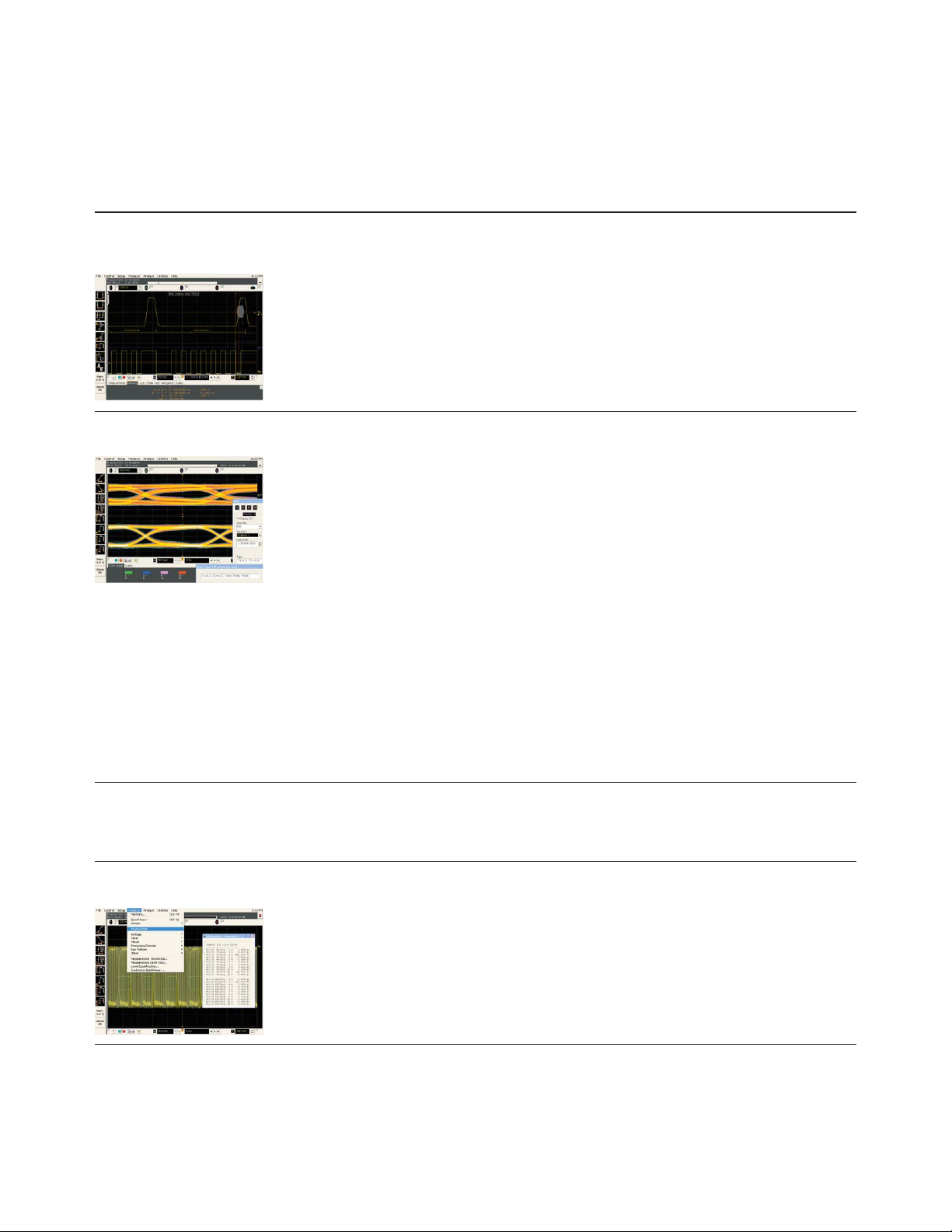
Ordering Information
Infiniium DSA/DSO90000A Series oscilloscopes and accessories
Infiniium DSA/DSO90000A Series application software (continued)
Accessories (continued) Description
N5391A/N5402A I
2
C/SPI serial data analysis software (Option 007)/Automotive serial data analysis
software (Option 008)
The N5391A low-speed serial data analysis (I
serial data analysis software (CAN/FlexRay) provides a fast and easy way to debug
inter-integrated circuit (I
or controlled area network (CAN) and FlexRay buses. Numerical decode values are
automatically displayed and synchronized below the captured signal’s waveform. A listing
window view with automatic click and zoom capability shows the index number, time
stamp value, address, data/remote/error frame type, and data content of all packets that
have been captured.
N5430A Infiniium user-defined function (Option 010)
The Agilent N5430A Infiniium user-defined function will open up new possibilities to
mathematical analysis features of Infiniium by creating the gateway to MATLAB from
MathWorks (www.mathworks.com/). You can now add your favorite MATLAB .m
scripts as “math function operators,” and use them just like any other standard functions
provided with the Infiniium. The scope passes data to MATLAB and then displays the
result back on the screen in real time. The screen shot shows a signal equalization
example using user-defined function.
Requires MATLAB software (sold separately).
Features:
• Seamless gateway to powerful MATLAB analysis functionality
• Real-time analysis, real-time update
• Requires XML programming and .m script file
• Supports two control variables and two sources
• Supports MATLAB version R14 SP1 and later
2
C) and 2-wire, 3-wire, or 4-wire serial peripheral interface (SPI),
2
C/SPI) software and N5402A automotive
Visit www.agilent.com/find/scope_forum_hints and share your user-defined function
experiences!
N5452A Infiniium application remote interface (Option 011)
The Agilent N5452A will allow users to control various compliance test applications
remotely using .NET languages.
E2699A My Infiniium integration package (standard application)
My Infiniium allows you to customize Infiniium GUI by letting you launch user-created
applications, such as those written for Agilent VEE Pro, NI LabVIEW, MATLAB or
Microsoft Excel, directly from the oscilloscope’s front panel or graphical user interface.
For more detailed information, please request Agilent publication number 5988-9934EN.
Visit www.agilent.com/find/share_your_app and share your My Infiniium experiences!
www.agilent.com/find/90000Ademo
33
Page 34
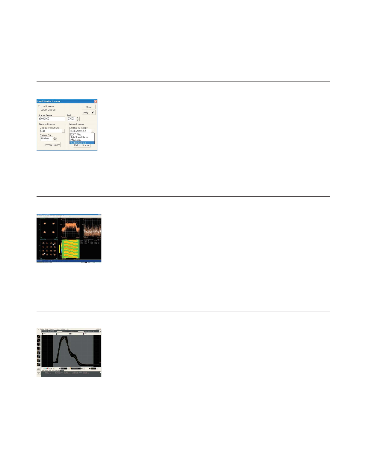
Ordering Information
Infiniium DSA/DSO90000A Series oscilloscopes and accessories
Infiniium DSA/DSO90000A Series application software (continued)
Accessories (continued) Description
N5435A Infiniium application server license
The Agilent N5435A Infiniium application server license allows you to transport your
scope application licenses from one oscilloscope to another through your server.
N5435A Options
001 EZJIT Plus server license 013 Fibre Channel compliance server license
002 EZJIT server license 014 SATA compliance server license
003 HSS SDA server license 015 SAS compliance server license
004 InfiniiScan server license 016 DDR2 clock/data compliance server license
005 Infiniium UDF server license 017 USB compliance server license
006 Low-speed serial server license 018 XAUI electrical validation server license
007 MyInfiniium server license 019 DisplayPort compliance server license
008 Ethernet compliance server license 020 DDR3 compliance server license
009 PCI Express server license 021 DDR1 compliance server license
011 HDMI compliance server license 022 MIPI D-PHY compliance software
012 FB-DIMM compliance server license
89600A Vector signal analysis software
Turn your scope into a wide band spectrum analyzer. Infiniium oscilloscopes team up
with the 89600A vector signal analysis software to provide powerful, flexible, wideband
signal analysis with up to 13 GHz bandwidth for applications including wideband
communications, modulated radar, and WiMedia-based MB-OFDM ultra-wide band.
Features include:
• Analysis bandwidth of up to 13 GHz depending on scope model. Multi-channel capture
for BBIQ and MIMO.
• Flexible analog and digital demodulation supports the most advanced, complex
modulation formats
• Flexible, powerful displays including EVM, CCDF, PDF, CPE, frequency error, I/O offset,
and spectrogram provide rapid insight into dynamic signal behavior
• The newest demodulation feature includes PHY Radio test support for Certified
Wireless USB, high-speed Bluetooth
MB-OFDM UWB technology
N5392A Ethernet electrical performance validation and compliance software
The Agilent N5392A Ethernet electrical performance validation and compliance software
performs a wide range of electrical tests to meet the Ethernet electrical specifications for
1000Base-T, 100Base-TX and 10Base-T systems as documented in the IEEE 802.3-2005
and ANSI X3.263-1995 standards.
Features:
• Test setup wizard guides you through test selection, configuration, connection,
execution, and results reporting
• Supports 1000Base-T, 100Base-TX and 10Base-T standards
• Supports 1000BASE-T disturbing signal measurements with the use of 33250A arbitrary
waveform generators
• Supports return loss measurements with most HP/Agilent vector network analyzers
• Test results report formally documents your test configuration, measurements made,
pass/fail status, and waveforms
• Pass/fail margin analysis provides an indication of how close your device is to meeting
a test specification
• Fixtures available: N5395B Ethernet test fixtures and N5396A jitter test cable
®
and wireless HDMI, all based on WiMedia
34
www.agilent.com/find/90000Ademo
Page 35
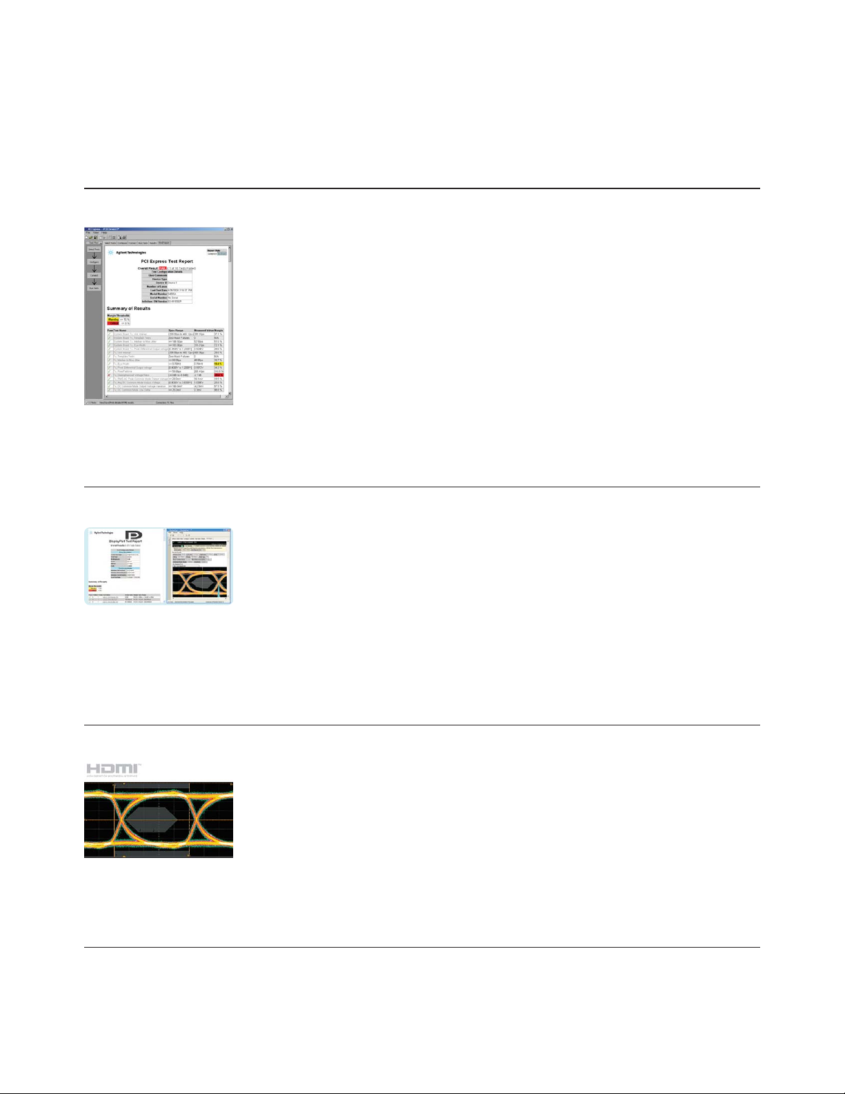
Ordering Information
Infiniium DSA/DSO90000A Series oscilloscopes and accessories
Infiniium DSA/DSO90000A Series application software (continued)
Accessories (continued) Description
N5393B PCI EXPRESS electrical performance validation and compliance software
The Agilent N5393B PCI EXPRESS electrical performance validation and compliance
software provides you with a fast and easy way to verify and debug your PCI EXPRESS
designs by automatically executing electrical checklist tests, and it displays the results in
a flexible report format.
N5393B utilizes the clock recovery method used in the official PCI-SIG signal quality test
methodology (“SigTest”) application, ensuring that your test results are consistent with
results from the SigTest application.
Features:
• Test setup wizard guides you through entire compliance test
• Wide-range of electrical tests are performed, significantly more than SigTest
• PCI-SIG SigTest clock recovery algorithm
• Automatic HTML report generation
• Pass/fail margin analysis
• Requires the E2688A serial data analysis software
• Compliance Test Fixtures available from PCI-SIG (CLB or CBB)
U7232A DisplayPort electrical performance validation and compliance software
Verify and debug your DisplayPort designs more easily with industry's only solution
for DisplayPort. Agilent U7232A provides you with a fast and easy way to verify and
debug your DisplayPort interface designs for sink and source ICs, motherboard systems,
computers and graphics cards. The DisplayPort electrical test software is designed for
use in DisplayPort Authorized Compliance Test Houses, so you can confidently use it to
execute DisplayPort electrical checklist tests as well as employ it as a development tool.
Features:
• DUT definition setup wizard for defining DUT capability
• Wide range of electrical tests
• Measurement process configurability
• Automated scope measurement setup
• Test results reports with pass/fail margin analysis
N5399A HDMI electrical performance validation and compliance software
The N5399A HDMI electrical performance validation and compliance software handles
all the electrical waveform tests as specified in the HDMI compliance test specification.
These include data eye, under and overshoot, clock jitter and duty cycle as well as interand intra-pair skew.
Features:
• Test setup wizard guides you through entire compliance test
• Ultimate test execution speed supporting 4 probe testing
• Automatic HTML report generation
• Software clock recovery feature tailored to HDMI 1.2/1.3
• Supports HDMI 1.2/1.3
• Fixtures available: N1080A
www.agilent.com/find/90000Ademo
35
Page 36
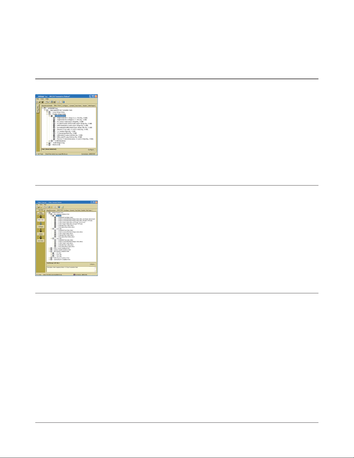
Ordering Information
Infiniium DSA/DSO90000A Series oscilloscopes and accessories
Infiniium DSA/DSO90000A Series application software (continued)
Accessories (continued) Description
N5409A Fully buffered DIMM
The Agilent N5409A fully buffered DIMM compliance application tool provides you with
a fast and easy way to characterize and evaluate the signal integrity of both your highspeed FB-DIMM signals as well as your reference clock. The tests performed by the
N5409A are based on the JEDEC high-speed point-to-point link specification.
Requires E2688A serial data analysis and N5400A EZJIT Plus jitter analysis software.
Three fixtures are available for testing AMBs, DIMMs and mother boards.
Features:
• Easy-to-use graphical test selection and setup
• Automatic HTML report generation
• RJ/DJ jitter analysis at 10
• Supports both JEDEC and Intel eye masks
• Built-in AMB control for test setup (DIMM and AMB testing)
• User configurable margin analysis
• Debug mode allows changes in test parameters giving you better insight into problems
N5410A Fibre Channel compliance application
–12
BER
The Agilent N5410A Fibre Channel compliance application provides you with a fast and
easy way to characterize and evaluate the signal integrity of your electrical Fibre-Channel
devices. Supporting FC4, FC2, and FC1 speeds, the N5410A allows you to specify the
measurement point at which you are probing your signal (delta, gamma, etc.). The tests
performed by the N5410A are based on the FC-PH (ANSI X3.230-1994) and FC-PH-2 Fibre
Channel - Physical and Signaling Interface specification.
Features:
• Easy-to-use graphical test selection and setup
• Supports 4.250 GBit/s, 2.125 GBit/s, and 1.0625 GBit/s speeds
• Supports testing at beta, delta, and gamma compliance points
• Automatic HTML report generation
• RJ/DJ jitter separation analysis at 10
• Physical layer measurements for rise/fall time, jitter, differential voltage, and eye mask
• Supports TCTF compliance load filter
• Debug mode allows changes in test parameters giving you better insight into problems
N5394A DVI compliance application
The N5394A DVI electrical performance validation and compliance software provides you
with a fast and easy way to verify and debug your digital visual interface (DVI) designs
for add-in cards, cables and motherboard systems. The DVI software allows you to
automatically execute DVI electrical checklist tests, and it displays the results in a flexible
report format. In addition to the measurement data, the report provides a margin analysis
that shows how closely your device passed or failed each test.
Requires an Agilent Infiniium Series oscilloscope with bandwidth of 4-GHz or higher,
the Silicon Image DVI Compliance Test Kit (which contains the clock recovery unit, test
point access fixtures, and cables), and at least two 3.5-GHz or higher InfiniiMax active
differential probes (1131A, 1132A, 1134A, 1168A or 1169A) with appropriate probe heads
(E2677A or N5381A solder-in or E2678A socketed).
–12
BER
36
Features:
• Test setup wizard guides you through test selection, configuration, connection,
execution, and results reporting
• Measurement connection setups are displayed
• Oscilloscope setup is automatically configured for each test
• Test results report documents test configuration, measurements made, pass/fail
status, margin analysis, and waveforms
www.agilent.com/find/90000Ademo
Page 37
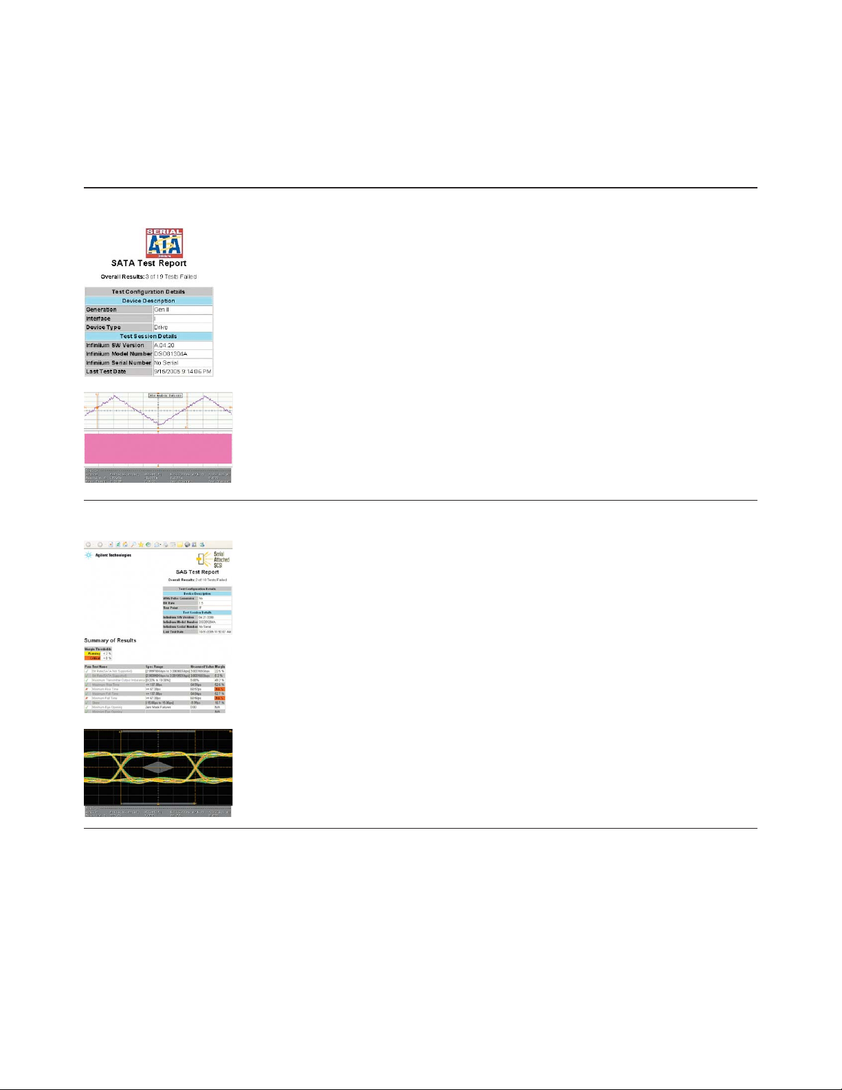
Ordering Information
Infiniium DSA/DSO90000A Series oscilloscopes and accessories
Infiniium DSA/DSO90000A Series application software (continued)
Accessories (continued) Description
N5411A SATA compliance test software
The N5411A SATA electrical performance validation and compliance software provides
you with a fast and easy way to validate and debug your SATA 1.5-Gbps (Gen 1)
and 3.0-Gbps (Gen 2) designs. N5411A allows you to automatically execute SATA II
electrical checklist tests at each of the i, m and x interface points, and displays the
results in a flexible report format. Agilent’s DSO81204B real-time scope-based method
of implementation (MOI) document for Serial ATA compliance testing, available from
SATA-IO Web site (www.sata-io.org/moi.asp), is based on N5411A.
For a fixture solution, COMAX H303000202 iSATA test fixture is available from CRUZ
System (www.cruzsystems.com).
Features:
• Available method of implementation (MOI) from SATA-IO
• Complete set of SATA transmitter electrical tests
• Test results report generation
• Debug mode provided
• Pass/fail margin analysis
N5412A Serial Attached SCSI (SAS)
Agilent’s N5412A Serial Attached SCSI (SAS) electrical performance validation and
compliance software provides you with a fast and easy way to validate and debug
your SAS 1.5-Gbps (SAS 150) and 3.0-Gbps (SAS 300) designs. N5412A allows you to
automatically execute SAS electrical checklist tests at each of the IT, CT, IR and CR
interface points, and displays the results in a flexible report format.
Additionally, Agilent currently provides a full set of compliance test fixtures, N5421A, for
the SFF-8482, SAS x2 internal drive/backplane connector interfaces. The N5421A kit also
includes the TX and RX transient circuit test loads.
Features:
• User configurable test setup wizard for ease-of-use
• Complete set of SAS IT/CT and IR/CR transmitter electrical tests
• Graphical HTML test results report generation
• Trials test capability for quick comparison of multiple port configurations
• Pass/fail margin analysis for simple characterization
www.agilent.com/find/90000Ademo
37
Page 38

Ordering Information
Infiniium DSA/DSO90000A Series oscilloscopes and accessories
Infiniium DSA/DSO90000A Series application software (continued)
Accessories (continued) Description
U7233A/N5413A/U7231A DDR1/DDR2/DDR3 compliance test application
The Agilent U7233A DDR1 compliance test application tool, N5413A DDR2 compliance
test application tool, and U7231A DDR3 compliance test application tool provide you with
a fast and easy way to characterize and evaluate your DDR1/DDR2/DDR3 designs. The
tests performed are based on the Intel DDR2 667/800 JEDEC Specification Addendum
Rev 1.1 (DDR2/N5413A), JESD79-3 DDR3 SDRAM Specification (DDR3/U7231A), and
JESD79E DDR SDRAM Specification (DDR1/U7233A).
Features:
• Industry's only automated test executive saves you time and ensures you get accurate
repeatable result
• Automatic HTML report generation speeds the documentation of worst case conditions
• The “compliance mode” provides you the clock jitter tests and the electrical test
• The “advance debug mode” provides you the eye diagram analysis, the mask test, and
the ringing test
N5416A USB compliance test software
The N5416A USB 2.0 compliance test software makes USB signal integrity testing as
simple as capturing the signals with your oscilloscope; eliminating the need to transfer
scope waveforms to a PC.
Features:
• Uses the USB-IF organization developed MATLAB scripts
• User friendly/comprehensive test setup wizard and reports
• Fast execution speed
• The USB-IF certified solution, support for hosts, devices, hubs and OTG
• Available fixtures: For USB 2.0 hi-speed testing, order the N5416A test software as
well as the E2649A USB 2.0 hi-speed test fixtures. For low/full speed testing order the
E2646A SQiDD board.
QP-SIGKit/QP-SIGKit4B IEEE-1394a/b electrical test tools
A pre-compliance test solution is available from Quantum Parametrics for use in
conjunction with Agilent 90000A Series oscilloscopes.
See http://www.quantumparametrics.com for additional information.
U7238A MIPI compliance test application
Agilent U7238A MIPI D-PHY compliance test software for Infiniium oscilloscopes enables
you with a fast and easy way to validate and debug your embedded D-PHY data links.
The D-PHY electrical test software allows you to automatically execute D-PHY electrical
checklist tests for CSI and DSI architectures, and displays the results in a flexible report
format. In addition to the measurement data, the report provides margin analysis that
shows how closely your product passed or failed each test.
38
Features:
• Automated setup and programming
• Increased accuracy, time-savings and repeatability
• Advanced debug modes for troubleshooting
• Automated margin analysis and pass/fail conformance reporting
www.agilent.com/find/90000Ademo
Page 39
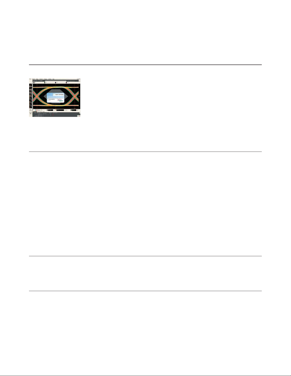
Ordering Information
Infiniium DSA/DSO90000A Series oscilloscopes and accessories
Infiniium DSA/DSO90000A Series application software (continued)
Accessories (continued) Description
N5431A XAUI electrical validation with 10GBASE-CX4, CPRI, OBSAI, and Serial RapidIO support
The XAUI electrical validation application improves your efficiency by providing fast and
accurate XAUI validation. With the superior signal integrity and probing provided by
the Agilent 90000 Series oscilloscopes, you will have confidence that devices that pass
testing with the N5431A are in conformance to the XAUI specifications as described in
IEEE 802.3-2005. You also have the flexibility of testing to the XAUI-derived 10GBASE-CX4,
CPRI, OBSAI RP3 and Serial Rapid IO standards.
Features:
• Fast setup, configuration, and test with wizard-driven framework
• Powerful characterization capability through the MultiTrial feature
• Flexibility to test to other XAUI derived standards
• Accurate measurements with the Agilent 90000 Series oscilloscope with superior
signal integrity and probing
• Unmatched probing flexibility with the InfiniiMax probing system
N5403A Noise reduction and bandwidth control option
Use the DSP noise reduction capability to reduce noise for a given measurement
bandwidth as shown in the tables below (supports 1.5 GHz and 2.5 GHz settings as well).
Included standard for DSO91304A and DSA Series scopes.
RMS noise floor
Volts/div 1 GHz 2 GHz 3 GHz 4 GHz 6 GHz 8 GHz 10 GHz 12 GHz 13 GHz
5 mV 98 μV 136 μV 169 μV 199 μV 259 μV 322 μV 380 μV 435 μV 467 μV
10 mV 120 μV 163 μV 200 μV 232 μV 295 μV 358 μV 418 μV 483 μV 536 μV
20 mV 189 μV 249 μV 298 μV 342 μV 424 μV 498 μV 568 μV 650 μV 758 μV
50 mV 443 μV 585 μV 697 μV 799 μV 985 μV 1.15 mV 1.29 mV 1.45 mV 1.73 mV
100 mV 881 μV 1.15 mV 1.36 mV 1.56 mV 1.92 mV 2.22 mV 2.49 mV 2.80 mV 3.37 mV
200 mV 1.74 mV 2.25 mV 2.66 mV 3.03 mV 3.71 mV 4.28 mV 4.81 mV 5.41 mV 6.58 mV
500 mV 4.54 mV 5.91 mV 7.00 mV 8.00 mV 9.91 mV 11.5 mV 13.1 mV 14.7 mV 17.4 mV
1 V 8.7 mV 11.4 mV 13.6 mV 15.6 mV 19.2 mV 22.3 mV 25.2 mV 28.5 mV 34.1 mV
Agilent offers the industry’s first noise reduction capability that allows you to reduce the
noise in your measurement to match the required bandwidth of the measurement so you
don’t include any more noise in your measurements than you have to.
E2625A Communication mask test kit
E2625A communication mask test kit comes with a set of electrical communication
adapters to ensure convenient, reliable and accurate connections to your device
under test. Included are more than 20 industry standard ANSI T1.102 and ITU-T G.703
communication signal mask templates.
www.agilent.com/find/90000Ademo
39
Page 40

Agilent Email Updates
t
www.agilent.com/find/emailupdates
Get the latest information on the products
and applications you select.
Agilent Direc
www.agilent.com/find/agilentdirect
Quickly choose and use your test
equipment solutions with confidence.
Agilent
Open
www.agilent.com/find/open
Agilent Open simplifies the process of
connecting and programming test systems
to help engineers design, validate and
manufacture electronic products. Agilent
offers open connectivity for a broad range
of system-ready instruments, open industry
software, PC-standard I/O and global
support, which are combined to more
easily integrate test system development.
www.lxistandard.org
LXI is the LAN-based successor to GPIB,
providing faster, more efficient connectivity.
Agilent is a founding member of the LXI
consortium.
Remove all doubt
Our repair and calibration services
will get your equipment back to you,
performing like new, when promised.
You will get full value out of your Agilent
equipment throughout its lifetime. Your
equipment will be serviced by Agilenttrained technicians using the latest
factory calibration procedures, automated
repair diagnostics and genuine parts. You
will always have the utmost confidence
in your measurements.
Agilent offers a wide range of additional
expert test and measurement services
for your equipment, including initial
start-up assistance, onsite education
and training, as well as design, system
integration, and project management.
For more information on repair and
calibration services, go to:
www.agilent.com/find/removealldoubt
www.agilent.com
www.agilent.com/find/90000A
For more information on Agilent
Technologies’ products, applications or
services, please contact your local Agilent
office. The complete list is available at:
www.agilent.com/find/contactus
Americas
Canada (877) 894-4414
Latin America 305 269 7500
United States (800) 829-4444
Asia Pacific
Australia 1 800 629 485
China 800 810 0189
Hong Kong 800 938 693
India 1 800 112 929
Japan 0120 (421) 345
Korea 080 769 0800
Malaysia 1 800 888 848
Singapore 1 800 375 8100
Taiwan 0800 047 866
Thailand 1 800 226 008
Europe & Middle East
Austria 01 36027 71571
Belgium 32 (0) 2 404 93 40
Denmark 45 70 13 15 15
Finland 358 (0) 10 855 2100
France 0825 010 700
Germany 07031 464 6333
Ireland 1890 924 204
Israel 972-3-9288-504/544
Italy 39 02 92 60 8484
Netherlands 31 (0) 20 547 2111
Spain 34 (91) 631 3300
Sweden 0200-88 22 55
Switzerland 0800 80 53 53
United Kingdom 44 (0) 118 9276201
Other European countries:
www.agilent.com/find/contactus
Revised: October 1, 2008
MATLAB is a U.S. registered trademark of
The MathWorks, Inc.
Windows is a U.S. registered trademark of
Microsoft Corporation.
Intel is a U.S. registered trademark of Intel
Corporation.
PCI EXPRESS and PCI-SIG are registered
trademarks of PCI-SIG.
Bluetooth and the Bluetooth logos are
registered trademarks owned by Bluetooth
SIG, Inc., U.S.A. and licensed to Agilent
Technologies, Inc.
Product specifications and descriptions
in this document subject to change
without notice.
© Agilent Technologies, Inc. 2008
Printed in USA, December 12, 2008
5989-7819EN
 Loading...