

Page 1
Infiniium 80000B Series Oscilloscopes
InfiniiMax Series Probes
2 GHz to 13 GHz Oscilloscope
Measurement Systems
Data Sheet
• 2 GHz to 13 GHz bandwidth
real-time oscilloscopes all with
up to 40 GSa/s sample rate
• Up to 2 Mpts MegaZoom deep
memory at 40 GSa/s sample
rates and 64 Mpts MegaZoom
deep memory at 4 GSa/s
• Industry’s lowest noise floor for
both oscilloscopes and probes
• Industry’s lowest jitter
measurement floor
• Industry’s lowest trigger jitter –
less than 500 fs rms
• Industry’s flattest frequency
response
• Industry’s only full bandwidth
probe system for all use
models – up to 13 GHz
bandwidth for differential
solder-in, browser and SMA
connections
• Industry’s only bandwidth
upgradeable series from 2 GHz
to 13 GHz via the After-Burner II
upgrade program
• Industry’s largest selection of
application software packages
• Includes touch screen, XGA
display, front-panel USB port,
2.93 GHz CPU and intensity
graded waveforms
Infiniium
80000B Series
Superior Signal
Integrity and Probing
for Your Application
The superior signal integrity,
probing and application software
selection of Agilent Technologies’
Infiniium 80000B Series and
InfiniiMax II probing system will
lead to improved measurements
and increased design margins.
The signal integrity advantages of
Agilent’s Infiniium 80000B Series
Scopes and InfiniiMax Probing
System include the industry’s
lowest noise floor, lowest jitter
measurement floor, lowest trigger
jitter and flattest frequency
response. These foundational
capabilities are crucial for
achieving accurate and repeatable
measurements. These superior
signal integrity capabilities
come from Agilent’s RF design
experience, proprietary packaging
technologies and unique CMOS
ADC architecture. Superior signal
integrity maximizes engineer’s
design margins by not wasting
any measurement accuracy
due to
the poor
noise,
jitter or
frequency
response
of the
scope or
probing
system.
Page 2

2
Benefits
The probing advantages of the
InfiniiMax Series probes include
the low noise and flat frequency
response mentioned above. The
InfiniiMax Series also offers the
industry’s widest selection of
probe amplifier bandwidths
(currently six) and the industry’s
widest variety of different probe
head types (currently nine).
InfiniiMax is also the only probing
system to offer the full 13 GHz
bandwidth for the differential
solder-in, differential browsing and
differential SMA use models. Since
its inception, the award-winning
InfiniiMax probe system has
provided maximum performance
with unmatched usability.
The application software for the
Infiniium 80000B Series is the
industry’s largest – currently
offering a choice of 23 different
application packages to tailor the
capabilities of the oscilloscope
to your specific measurement
requirements. Application
specific software solutions
include compliance test packages
for industry standards such as:
PCI-Express®, DDR, FBD, SATA,
SAS, FC, DVI, HDMI, USB, FW
and Ethernet as well as more
general purpose jitter and serial
data analysis packages. Agilent
is also the industry’s only vendor
to offer innovative packages for
ultra-wideband vector signal
analysis, noise reduction and the
brand new InfiniiScan event
identification software.
The industry leading signal
integrity, probing and software
application capabilities of the
Infiniium 80000B Series scopes
and InfiniiMax Series probes
have recently won three
industry awards.
U.S. Navy imagery used in illustration without endorsement expressed or implied.
Superior signal integrity and
probing for your application
Agilent doesn’t only deliver
industry leading oscilloscope
performance. It also uses the
company’s extensive technology
base to provide superior signal
integrity, probing and analysis
software for the designer’s
specific application. The most
noteable benefits of the Agilent
solution are:
Signal integrity
• Industry’s lowest scope
noise floor
• Industry’s lowest jitter floor
• Industry’s lowest trigger jitter
• Industry’s flatest frequency
response
• Industry’s leading hardware
sensitivity
• Industry’s only bandwidth
upgradeable series
Probing
• Industry’s lowest probe
noise floor
• Industry’s widest range of
probe amplifier bandwidths
• Industry’s widest range of
probe head types
• Industry’s only full bandwidth
probing system
• Industry’s flatest probe
frequency response
Applications
• Industry’s largest set
of applications
• Industry’s only event
identification software
• Industry’s only wideband
spectrum analyzer software
• Industry’s only noise
reduction software
• Industry’s only calibrated
jitter measurement
• Industry’s only compliance
test framework to support
SAS, FC, DDR, FBD, USB,
SATA, Ethernet, PCI-Express,
DVI and HDMI
Page 3

3
www.agilent.com/find/infiniimaxII
80000B Series Infiniium oscilloscopes
Real-time bandwidth on Equivalent-time bandwidth on Real-time bandwidth on
Model 2 channels and 40 GSa/s 4 channels with 1.56 ps point spacing 4 channels at 20 GSa/s
DSO81304B 13 GHz* 13 GHz 8 GHz
DSO81204B 12 GHz 12 GHz 8 GHz
DSO81004B 10 GHz 10 GHz 8 GHz
DSO80804B 8 GHz 8 GHz 8 GHz
DSO80604B 6 GHz 6 GHz 6 GHz
DSO80404B 4 GHz 4 GHz 4 GHz
DSO80304B 3 GHz 3 GHz 3 GHz
DSO80204B 2 GHz 2 GHz 2 GHz
* Real-time DSP enhanced bandwidth
Maximum memory depth for all DSO80000B Series
Standard acquisition memory 0.5 Mpts on 2 channels, 0.25 Mpts on 4 channels
Optional acquisition memory 2 Mpts on 2 channels, 1 Mpts on 4 channels
this option also enables 64 Mpts on 2 channels at 4 GSa/s, 32 Mpts on 4 channels ≤ 2 GSa/s
Maximum memory in equivalent-time modes always 0.25 Mpts per channel
Benefits (continued)
Page 4

4
Benefits (continued)
Example 1: How much bandwidth do I need to measure a given rise/fall time accurately?
Rise/fall time (20 - 80%) 3% accuracy 10% accuracy 20% accuracy
100 ps 5.6 GHz 4.8 GHz 4.0 GHz
75 ps 7.5 GHz 6.4 GHz 5.3 GHz
60 ps 9.3 GHz 8.0 GHz 6.7 GHz
50 ps 11.2 GHz 9.6 GHz 8.0 GHz
40 ps 14.0 GHz 12.0 GHz 10.0 GHz
30 ps 18.7 GHz 16.0 GHz 13.3 GHz
Notes:
Maximum signal frequency content = 0.4/rise time (20 - 80%)
Scope bandwidth required = 1.4 x maximum signal frequency for 3% accuracy measurements
Scope bandwidth required = 1.2 x maximum signal frequency for 5% accuracy measurements
Scope bandwidth required = 1.0 x maximum signal frequency for 10% accuracy measurements
Example 2: How much bandwidth do I need for a given high-speed serial bus clock rate?
Fundamental frequency 3rd harmonic frequency 5th harmonic frequency
Serial bus clock rate of data signal of data signal of data signal
2.5 Gb/s 1.25 GHz 3.75 GHz 6.25 GHz
4.25 Gb/s 2.125 GHz 6.375 GHz 10.625 GHz
5.0 Gb/s 2.5 GHz 7.5 GHz 12.5 GHz
6.0 Gb/s 3.0 GHz 9.0 GHz 15.0 GHz
7.0 Gb/s 3.5 GHz 10.5 GHz 17.5 GHz
8.5 Gb/s 4.25 GHz 12.75 GHz 21.25 GHz
Page 5

5
www.agilent.com/find/infiniimaxII
Benefits (continued)
InfiniiMax II Series probe amplifiers
Model Bandwidth Description
1169A 12 GHz (spec) 13 GHz (typical) InfiniiMax II probe amplifier – order one or more probe heads
1168A 10 GHz InfiniiMax II probe amplifier – order one or more probe heads
InfiniiMax II probe amplifier specifications: Dynamic range = 3.3 V, DC offset range = ± 16 V, maximum voltage = ± 30 V
InfiniiMax I Series probe amplifiers
Model Bandwidth Description
1134A 7 GHz InfiniiMax I probe amplifier – order one or more probe heads
1132A 5 GHz InfiniiMax I probe amplifier – order one or more probe heads
1131A 3.5 GHz InfiniiMax I probe amplifier – order one or more probe heads
1130A 1.5 GHz InfiniiMax I probe amplifier – order one or more probe heads
InfiniiMax I probe amplifier specifications: Dynamic range = 5 V, DC offset range = ± 12 V, maximum voltage = ± 30 V
Page 6

6
Benefits (continued)
InfiniiMax II Series probe heads
InfiniiMax II Series probe heads are recommended for 1169A/68A probe amplifiers. When used with a DSO81304B, the
N5380A, N5381A, and N5382A will typically achieve 13 GHz bandwidth.
Differential measurement Single-ended measurement
Probe head Model number (BW, input C, input R) (BW, input C, input R)
Hi-BW differential SMA N5380A 12 GHz 12 GHz
Hi-BW differential solder-in N5381A 12 GHz, 0.21 pF, 50 kΩ 12 GHz, 0.35 pF, 25 kΩ
Hi-BW differential browser N5382A 12 GHz, 0.21 pF, 50 kΩ 12 GHz, 0.35 pF, 25 kΩ
InfiniiMax I Series probe heads (can be used with 1169A/68A probe amplifiers with limitations)
Differential measurement Single-ended measurement
Probe head Model number (BW, input C, input R) (BW, input C, input R)
Differential solder-in E2677A 12 GHz, 0.27 pF, 50 kΩ 12 GHz, 0.44 pF, 25 kΩ
(Higher loading, high frequency
response variation)
Differential socket E2678A 12 GHz, 0.34 pF, 50 kΩ 12 GHz, 0.56 pF, 25 kΩ
(Higher loading)
Differential browser – wide span E2675A 6 GHz, 0.32 pF, 50 kΩ 6 GHz, 0.57 pF, 25 kΩ
Differential SMA E2695A 8 GHz 8 GHz
Single-ended solder-in E2679A N/A 6 GHz, 0.50 pF, 25 kΩ
(must bandlimit input to ≤ 6 GHz)
Single-ended browser E2676A N/A 6 GHz, 0.67 pF, 25 kΩ
Differential kit E2669A
(includes E2675A,
E2677A and E2678A)
Single-ended kit E2668A
(includes E2676A,
E2679A and E2678A)
High-impedance adapter E2697A
(includes 500 MHz
passive probe)
Page 7

7
www.agilent.com/find/infiniimaxII
Benefits (continued)
Infiniium 80000B Series support for industry bus standards
Serial data analysis (E2688A)
Recommended Jitter SW clock 8b/10b Mask Compliance
Bus standard Bit rate BW
1
analysis2recovery decode testing testing Test fixtures
Ethernet 250 Mbs 2 GHz Yes Yes N/A Yes N5392A N5395B
USB 2.0 up to 480 Mbs 2 GHz Yes Yes N/A Yes N5416A E2649A
DDR I/II up to 800 MTs 4 GHz Yes N/A N/A No N5413A No
SATA 1.5 Gbps 1.5 Gbps 6 GHz Yes Yes Yes Yes N5411A Crescent Heart
SAS 150 1.5 Gbps 6 GHz Yes Yes Yes Yes N5412A N5421A
DVI 1.65 Gbps 4 GHz Yes Yes Yes Yes N5394A Silicon Image
HDMI up to 1.65 Gbps 4 GHz Yes Yes Yes Yes N5399A N5405A
Fibre Channel 2.125 Gbps 4 GHz Yes Yes Yes Yes N5410A No
PCI Express I 2.5 Gbps 6 GHz Yes Yes Yes Yes N5393A
3
PCI-SIG
®
ExpressCard 2.5 Gbps 6 GHz Yes Yes Yes Yes N5393A
3
PCMCIA.org
InfiniBand 2.5 Gbps 6 GHz Yes Yes Yes Yes No Fujikura
Advanced TCA 2.5 Gbps 6 GHz Yes Yes Yes Yes No No
SATA 3Gbps 3.0 Gbps 10 GHz Yes Yes Yes Yes N5411A
4
Crescent Heart
SAS 300 3.0 Gbps 10 GHz Yes Yes Yes Yes N5412A
4
N5421A
10G Ethernet 3.125 Gbps 8 GHz Yes Yes N/A Yes No No
XAUI 3.125 Gbps 8 GHz Yes Yes Yes Yes No No
Serial Rapid IO up to 3.125 Gbps 8 GHz Yes Yes Yes Yes No No
FireWire up to 3.2 Gbps 8 GHz Yes Yes N/A N/A Yes - QP Quantum Para.
Fibre Channel 4.25 Gbps 10 GHz Yes Yes Yes Yes N5410A
4
No
FBD I up to 4.8 Gbps 12 GHz Yes Yes N/A Yes N5409A
4
N4235A/36/38A
PCI Express II 5.0 Gbps 12 GHz Yes Yes Yes No No No
InfiniBand II 5.0 Gbps 12 GHz Yes Yes Yes No No No
SATA 6Gbps 6.0 Gbps 13 GHz Yes Yes Yes No No No
SAS 600 6.0 Gbps 13 GHz Yes Yes Yes No No No
Fibre Channel 8.5 Gbps 13 GHz Yes Yes Yes No No No
FBD II up to 9 Gbps 13 GHz Yes Yes N/A No No No
1 Recommended bandwidth is derived from a combination of data rate and edge speed
2 Jitter analysis solutions: EZJIT (E2681A), EZJIT Plus (N5400A), oscilloscope tools (E2690B)
3 Requires E2688A serial data analysis
4 Requires E2688A serial data analysis and N5400A EZJIT Plus jitter analysis
Page 8
8
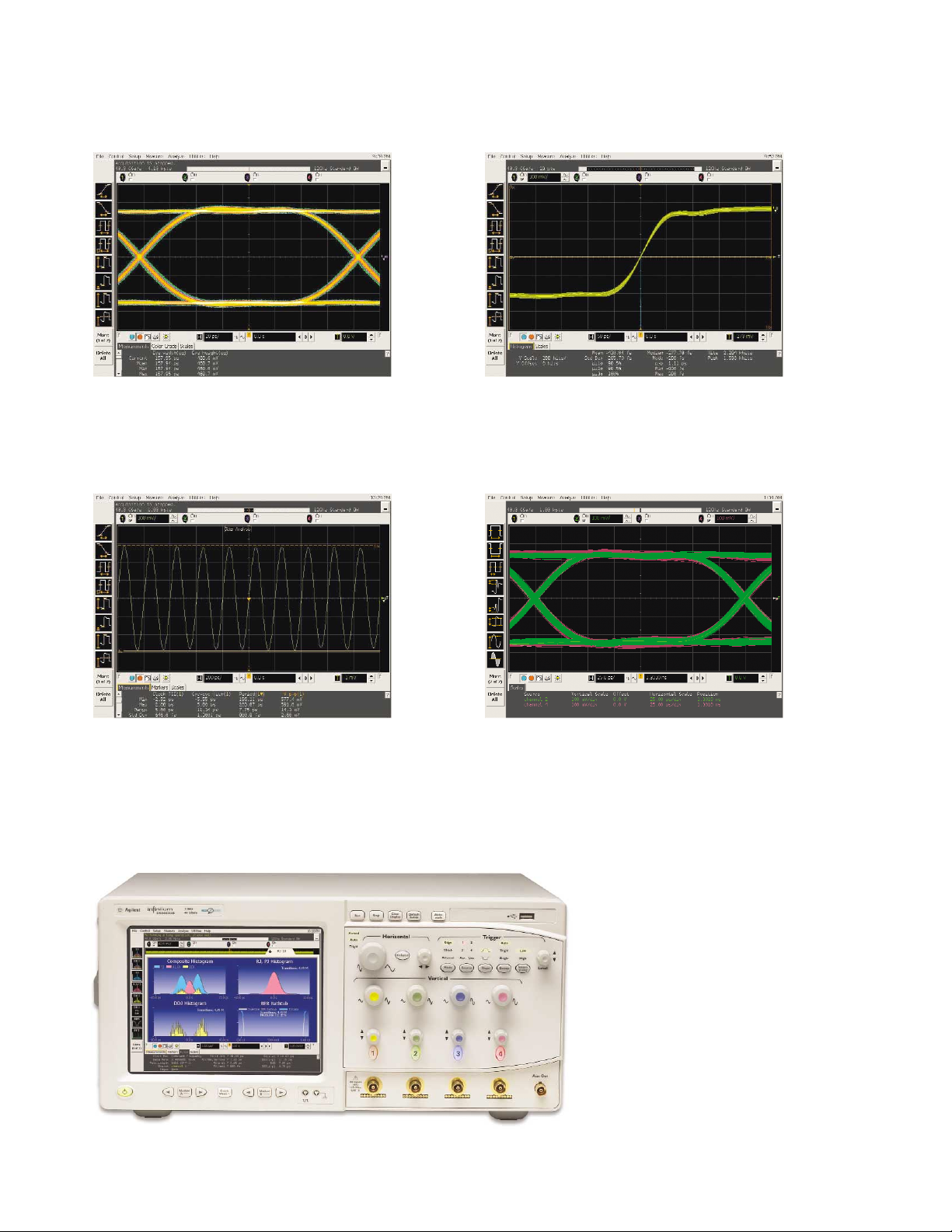
The industry’s lowest noise floor delivers superior
measurement results and maximizes design
margins. (see page 12 for noise floor
characteristics)
The industry’s lowest trigger jitter, less than
500 fs rms, facilitates accurate waveform
viewing of multiple waveforms.
Benefits (continued)
The industry’s lowest jitter measurement floor
minimizes the oscilloscopes contribution to jitter
measurements and results in superior compliance
test results.
The industry’s flattest frequency response leads
to excellent correlation between scope only
(white trace) and scope plus probe (red trace)
measurements as shown in this dual infinite
persistence eye diagram.
EZJIT Plus jitter decomposition supports
arbitrary data patterns. Agilent’s
industry-leading selection of application
software packages facilitate rapid analysis
of acquired data into measurement results.
Page 9

9
www.agilent.com/find/infiniimaxII
Overview of Infiniium 80000B Series Application Software
Jitter
Application software package U.S. list
E2681A EZJIT jitter analysis (option 002) $4,000
N5400A EZJIT Plus jitter analysis (option 004) $8,000
E2690B Amherst oscilloscope tools Various
Analysis
Application software package U.S. list
E2688A SDA high-speed serial data analysis (option 003) $8,000
N5414A InfiniiScan event identification software $5,000
N5391A I2C/SPI serial data analysis $1,500
N5402A CAN serial data analysis $1,500
89601A Vector signal analysis ≥ $7,000
Compliance
Application software package U.S. list
N5392A Ethernet compliance $3,000
N5393A PCI Express compliance $2,000
N5394A DVI compliance $4,000
N5399A HDMI compliance $4,000
N5409A Fully Buffered DIMM compliance $4,000
N5410A Fiber channel compliance $4,000
N5411A SATA I/II compliance $3,000
N5412A SAS compliance $3,000
N5413A DDR2 clock characterization $3,000
N5416A USB compliance $2,000
Fire-wire compliance (Quantum Parametrics) Various
Utilities
Application software package U.S. list
N5403A Noise reduction (option 005) $2,000
E2625A Communications mask test kit $3,000
E2699A My Infiniium integration package (option 006) $800
E2682A Voice control option $500
Page 10

10
Infiniium: “It’s like someone who sits down and actually uses
a scope designed this one.”
Steve Montgomery, Director of Engineering, Linx Technologies
Up to 40 GSa/s sample rate on two channels
significantly reduces the chances of aliasing,
increases measurement accuracy, and delivers the
full real-time bandwidth of the oscilloscope on two
channels simultaneously.
Four channels at 20 GSa/s with 8 GHz real-time
bandwidth or full bandwidth equivalent time modes
are also available.
Get fast answers to your questions with
the built-in information system. Infiniium’s
task-oriented Setup Guide provides step-by-step
instructions for several advanced measurements
and procedures. A 2.93 GHz Celeron CPU processes
measurements quickly.
See your signal more clearly with a large (8.4-inch)
XGA (1024 x 768) high-resolution color display.
Infiniium’s bright TFT display with anti-glare
coating lets you see the details of your signal from
all angles.
≥ 40 Gb hard drive, a front-panel high-speed USB
2.0 port and four rear panel high-speed USB 2.0
ports make it easy to save setup files, data files,
screen shots, etc.
Identify anomalies easily with a 256 level intensity
graded or color-graded persistence display which
provides a three dimensional view of your signals.
Label waveforms and add notes to your screen
captures – Infiniium’s keyboard makes it easy.
The built-in touch screen or a plug-in mouse
can be used to access all menus, drag and drop
measurement icons or position markers.
Easy access to advanced features like
math functions and FFTs, is provided by the
Windows®-based graphical user interface. This GUI
also gives you unique capabilities like drag-and-drop
measurements and zooming, and offers a graphical
equivalent to all front panel controls.
Remote access with Web-enabled connectivity,
e-mail on trigger, and GPIB over LAN allows you to
access your scope from remote locations.
64 Mpts acquisition memory at 4 GSa/s
sample rate on two channels allows you to capture
long time windows at high resolution – such as
identifying glitches due to a power supply start-up
from reset.
QuickMeas+ key gives you any five automated
measurements with a push of a button. You can
also configure this key to print/save screen shots,
save waveforms, or load a favorite setup.
Infiniium: Award-winning scopes
Infiniium has received ten industry
awards to date, including EDN’s
“Innovation of the Year” award
(twice) and T&M World’s “Best in
Test.” Agilent is committed to
breaking new ground and providing
tools that bring unique value to
our customers.
Page 11
11
www.agilent.com/find/infiniimaxII
Zoom and search with instant response. Zoom into
your signal using the horizontal scale knob and
search through your waveform with the position
knob. MegaZoom technology allows you to find
your area of interest quickly and easily – even with
64 Mpts waveforms.
Built-in CD-R drive on rear panel allows you to
update the system software conveniently and can
be used to install third-party application packages.
Hands-free operation with the Infiniium
VoiceControl option. Just speak into the
microphone to operate front-panel controls.
Segmented memory acquisition mode captures
bursting signals at maximum sample rate without
consuming memory during periods of inactivity.
Removable hard disk drive option is available for
added data security.
Install third-party software packages such as
Excel, LabView, Agilent Vee, MATLAB®, anti-virus
software, and more to perform customized
processing and automation of your oscilloscope
or to make the scope compliant to the network
environment of your company.
An external monitor allows you to run third-party
applications on a large, high-resolution XGA
display while using the scope’s built-in monitor
for high-speed waveform display.
Windows XP Pro operating system.
A familiar interface makes simple tasks simple.
Infiniium’s analog-like front panel has a full set
of controls color coded to the waveforms and
measurements, making simple tasks simple.
One-year standard warranty and a variety of
Agilent support options protect your investment
for the long term.
10 MHz reference clock can be input to or
output from the scope to allow precise timebase
synchronization with RF instruments or
logic analyzers.
A new 18 GHz, BNC-compatible connector
provides a high signal fidelity connection to Agilent
active probes, SMA adapters, and standard BNCs.
AutoProbe interface completely configures your
scope for use with the InfiniiMax probing system
and previous generation Agilent active probes.
10/100 Mbps LAN interface lets you easily print
waveforms on networked printers, save your results
on your office PC, share information with others,
and control the scope over the Web.
Page 12
E2679A 6 GHz
extremely small
single-ended, solder-in
probe heads for probing of
even the hardest-to-reach
single-ended signals.
E2695A 8 GHz
differential SMA
probe head allows
you to connect two
SMA cables to make a
differential measurement
on a single scope channel.
12
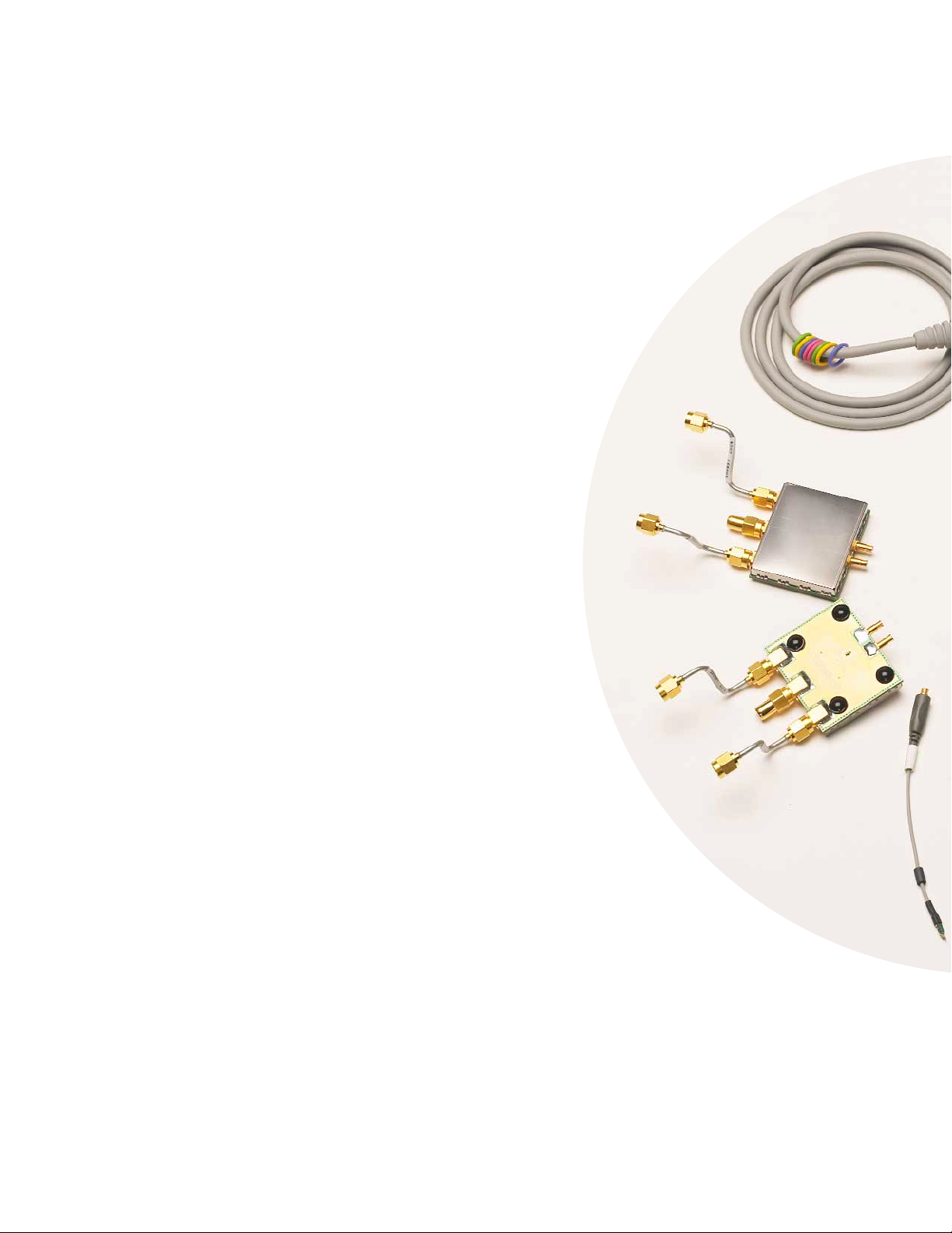
InfiniiMax II: The World’s Best High-Speed Probing System
Just Keeps Getting Better
N5380A 13 GHz
Hi-BW differential
SMA probe head
provides maximum
bandwidth for
SMA fixtured
differential pairs.
InfiniiMax offers you the highest performance
available for measuring differential and
single-ended signals, with flexible connectivity
solutions for today’s high-density ICs and
circuit boards.
InfiniiMax probes have fully characterized
performance for all of their various probe heads.
This includes:
• Swept frequency response plot
• Common mode rejection vs. frequency plot
• Impedance vs. frequency plot
• Time-domain probe loading plot
• Time-domain probe tracking plot
One-year standard warranty on active probes and
a variety of Agilent support options to choose from.
Controlled impedance transmission lines in every
probe head deliver full performance versus the
performance limitations produced by traditional
wire accessories.
Probe interface software allows you to save the
calibration information for up to 10 different probe
heads per channel and will automatically retrieve
calibration data for a probe amplifier as it is
attached to the scope.
High-input impedance active probes minimize
loading, support differential measurements and DC
offset, and can compensate for cable loss.
Probe calibration software delivers the most
accurate probe measurements, linear phase
response and allows various probe combinations
to be deskewed to the same reference time.
A flat frequency response over the entire probe
bandwidth eliminates the distortion and
frequency-dependent loading effects that are
present in probes that have an in-band resonance.
Probe Performance Plots Available
The InfiniiMax II probe manuals contain an extensive set of
performance plots (bandwidth, probe tracking, CMRR, step
response, impedance) for various probe configurations.
See the following web site for this information
www.cos.agilent.com/manuals/scopes/01169-9700_man.pdf
N5380A
E2695A
E2679A
Page 13
N5382A 13 GHz Hi-BW differential browser
provides maximum bandwidth for hand-held
or probe holder use. Variable spacing from
0.2 to 3.3 mm (8 to 130 mills).
E2675A 6 GHz differential browser is the best
choice for general-purpose trouble-shooting
of differential or single-ended signals with
z-axis compliance and variable spacing from
0.25 - 5.80 mm (10 - 230 mills).
E2676A 6 GHz Single-ended browser is the best
choice for general purpose probing of single-ended
signals when small size of the probe head is the
primary consideration.
E2677A 12 GHz solder-in differential probe
head can be attached to very small geometry
circuits for measuring both single-ended and
differential signals. External mini-coaxial resistors
facilitate wider span but have increased high-frequency
response variation relative to N5381A.
E2678A 12 GHz
differential socket
probe head can be
used to measure
either differential or
single-ended signals
via a plug-on socket
connection.
13
www.agilent.com/find/infiniimaxII
Six different InfiniiMax probe amplifiers from 1.5 GHz to 13 GHz are
available for matching your probing solution to your performance and
budget requirements. The 1168/69A InfiniiMax II amplifiers offer the
highest bandwidth and the lowest noise floors. The 1134/32/31/30A
offer a more cost effective solution and wider dynamic range.
N5381A 13 GHz Hi-BW solder-in differential
probe head provides maximum bandwidth and
minimizes capacitive loading to ≤ 210 fF. Variable
spacing from 0.2 to 3.3 mm (8 to 130 mills).
E2678A
E2677A
N5381A
E2676A
E2675A
N5382A
A SMP microwave extension cable from
Gore is available for extending the reach of
InfiniiMax probes into tight environments
or into test chambers (Gore part number
PRP042105-01, page 30).
Page 14

14
Infiniium 80000B Series Performance Characteristics
Vertical
Input channels 4
Analog bandwidth (–3 dB)*
10
80204B 80304B 80404B 80604B 80804B 81004B 81204B 81304B
2 GHz 3 GHz 4 GHz 6 GHz 8 GHz 10 GHz 12 GHz 12 GHz
DSP enhanced bandwidth
9
81304B: 13 GHz using DSP enhanced bandwidth mode
Rise time/fall time 80204B 80304B 80404B 80604B 80804B 81004B 81204B 81304B
10 - 90% 212 ps 153 ps 105 ps 70 ps 54 ps 42 ps 36 ps 33 ps
20 - 80% 152 ps 108 ps 91 ps 48 ps 38 ps 30 ps 25 ps 23 ps
Input impedance 50 Ω ±3%
Sensitivity
1
1 mV/div to 1 V/div
Input coupling DC
Vertical resolution
2
8 bits, ≥ 12 bits with averaging
Channel to channel isolation DC to 3 GHz: 60 dB
(any two channels with 3 GHz to 8 GHz: 40 dB
equal V/div settings) 8 GHz to BW: 35 dB
DC gain accuracy*
1
± 2% of full scale at full resolution channel scale
Maximum input voltage* ± 5 V
Offset range Vertical sensitivity: Available offset:
0 mV/div to ≤ 40 mV/div ± 0.4 V
> 40 mV/div to ≤ 75 mV/div ± 0.9 V
> 75 mV/div to ≤ 130 mV/div ± 1.6 V
> 130 mV/div to ≤ 240 mV/div ± 3.0 V
> 240 mV/div ± 4.0 V
Offset accuracy*
1
≤ 3.5 V: ± (2% of channel offset + 1% of full scale) +1 mV
> 3.5 V: ± (2% of channel offset + 1% of full scale)
Dynamic range ± 4 div from center screen
DC voltage measurement accuracy*
1
Dual cursor: ± [(DC gain accuracy)+(resolution)]
Single cursor: ± [(DC gain accuracy)+(offset accuracy)+(resolution/2)]
RMS noise floor (scope only) 80204B 80304B 80404B 80604B 80804B 81004B 81204B 81304B
Volts/div 5 mV 131 µV 160 µV 188 µV 239 µV 280 µV 340 µV 390 µV 420 µV
10 mV 154 µV 187 µV 218 µV 273 µV 310 µV 380 µV 440 µV 490 µV
20 mV 229 µV 272 µV 316 µV 392 µV 470 µV 530 µV 610 µV 730 µV
50 mV 534 µV 637 µV 737 µV 911 µV 1.1 mV 1.2 mV 1.4 mV 1.7 mV
100 mV 1.0 mV 1.2 mV 1.4 mV 1.8 mV 2.1 mV 2.3 mV 2.7 mV 3.3 mV
200 mV 2.0 mV 2.5 mV 2.8 mV 3.5 mV 4.1 mV 4.7 mV 5.3 mV 6.6 mV
500 mV 5.4 mV 6.4 mV 7.5 mV 9.3 mV 11 mV 12 mV 14 mV 17 mV
1 V 10.4 mV 12.5 mV 14.5 mV 18.0 mV 21 mV 24 mV 27 mV 34 mV
RMS noise floor (scope with probe) 80204B 80304B 80404B 80604B 80804B 81004B 81204B 81304B
w/1131A w/1131A w/1132A w/1134A w/1168A w/1168A w/1169A w/1169A
Volts/div 20 mV 3.2 mV 3.4 mV 3.6 mV 4.2 mV 2.7 mV 2.7 mV 2.9 mV 3.0 mV
50 mV 3.3 mV 3.4 mV 3.6 mV 4.2 mV 2.8 mV 2.9 mV 3.1 mV 3.4 mV
100 mV 3.4 mV 3.6 mV 3.8 mV 4.4 mV 3.3 mV 3.5 mV 3.8 mV 4.6 mV
200 mV 3.8 mV 4.2 mV 4.5 mV 5.3 mV 5.2 mV 5.6 mV 6.2 mV 7.8 mV
500 mV 6.0 mV 6.9 mV 7.9 mV 9.9 mV 12 mV 13 mV 14 mV 17 mV
1 V 10 mV 12 mV 14 mV 18 mV 22 mV 24 mV 27 mV 34 mV
Page 15

15
www.agilent.com/find/infiniimaxII
Infiniium 80000B Series Performance Characteristics (continued)
Horizontal
Main timebase range 5 ps/div to 20 s/div real-time, 5 ps/div to 500 ns/div equivalent-time
Main timebase delay range –200 s to 200 s real-time, –25 µs to 200 s equivalent-time
Delayed timebase range 1 ps/div to current main time scale setting
Channel deskew ± 25 µs range, 100 fs resolution
Time scale accuracy
3
± 1 ppm pk
Delta-time measurement accuracy
6,7
80204B 80304B 80404B 80604B 80804B 81004B 81204B 81304B
≥ 256 Averages, rms 250 fs rms 150 fs rms 100 fs rms 80 fs rms 55 fs rms 35 fs rms 35 fs rms 45 fs rms
≥ 256 Averages, peak 500 fs peak 500 fs peak 500 fs peak 500 fs peak 500 fs peak 500 fs peak 500 fs peak 500 fs peak
Averaging disabled, rms 2.0 ps rms 2.0 ps rms 2.0 ps rms 1.0 ps rms 0.9 ps rms 0.8 ps rms 0.8 ps rms 0.9 ps rms
Averaging disabled, peak 6 ps peak 6 ps peak 6 ps peak 5 ps peak 5 ps peak 5 ps peak 5 ps peak 5 ps peak
Jitter measurement floor
6
80204B 80304B 80404B 80604B 80804B 81004B 81204B 81304B
Time interval error 1.10 ps rms 0.90 ps rms 0.85 ps rms 0.75 ps rms 0.70 ps rms 0.65 ps rms 0.65 ps rms 0.70 ps rms
Period jitter 1.6 ps rms 1.3 ps rms 1.1 ps rms 1.0 ps rms 0.9 ps rms 0.8 ps rms 0.8 ps rms 0.9 ps rms
N-cycle, cycle-cycle jitter 2.6 ps rms 2.1 ps rms 1.9 ps rms 1.6 ps rms 1.4 ps rms 1.3 ps rms 1.3 ps rms 1.4 ps rms
Page 16

16
Infiniium 80000B Series Performance Characteristics (continued)
Acquisition
Maximum real-time sample rate 40 GSa/s (2 channels simultaneously)
20 GSa/s (4 channels simultaneously)
Memory depth per channel
Standard 524,288 (2 channels) 262,144 (4 channels)
Option 001 2,050,000 (2 channels) 1,025,000 (4 channels)
65,600,000 at 4 GSa/s (2 channels) 32,800,000 ≤ 2 GSa/s (4 channels)
Sampling modes
Real-time Successive single-shot acquisitions
Real-time with averaging Selectable from 2 to 4096
Real-time with peak detect 2 GSa/s peak detect (4 channels), 4 GSa/s peak detect (2 channels)
Real-time with hi resolution Real-time boxcar averaging reduces random noise and increases resolution
Equivalent-time (alternating real-time) Full bandwidth on all 4 channels, 262,144 sample points maximum memory.Acquires channels 1
and 3 simultaneously, followed by channels 2 and 4 simultaneously on subsequent triggers at
40 GSa/s each. High sample rate delivers excellent signal fidelity and throughput.
Segmented memory Captures bursting signals at maximum sample rate without consuming memory during periods of
inactivity. Selectable number of segments up to 16,384 with Option 001 deep memory installed.
Minimum intersegment time (the time between the end of the previous acquisition and the
beginning of the next acquisition) of 20 µs. See the table below for various performance points.
Infiniium 80000B Series
Maximum number
of segments Standard memory Optional memory
4 channel 2 channel 4 channel 2 channel
Sample rate mode mode mode mode
40 GSa/s N/A 128 N/A 4096
20 GSa/s 64 128 4096 8192
5 GSa/s - 10 GSa/s 64 128 8192 8192
≤ 4 GSa/s 128 256 16384 16384
Maximum trigger
rate (typical) 1 channel on 2 channel on (2 ch mode)
Sample rate 1 k pts 10 k pts 1 k pts 10 k pts
40 GSa/s 33 kHz 22 kHz 31 kHz 21 kHz
20 GSa/s 41 kHz 24 kHz 37 kHz 22 kHz
5 GSa/s - 10 GSa/s 47 kHz 25 kHz 42 kHz 23 kHz
4 GSa/s 50 kHz 45 kHz 42 kHz 38 kHz
2 GSa/s 50 kHz 43 kHz 42 kHz 36 kHz
Filters
Sin(x)/x Interpolation On/off selectable FIR digital filter. Digital signal processing adds points between acquired data
points to enhance measurement accuracy and waveform display quality.
Page 17

17
www.agilent.com/find/infiniimaxII
Infiniium 80000B Series Performance Characteristics (continued)
Trigger
Sensitivity
1
Internal Low
1
2.0 div p-p 0 to 5 GHz
Internal High
1
0.3 div p-p 0 to 4 GHz, 1.0 div p-p 4 to 7.5 GHz
Auxiliary DC to 1 GHz: 200 mV p-p into 50 Ω
Level range
Internal ± 4 div from center screen or ± 4 Volts, whichever is smallest
Auxiliary ± 5 V, also limit input signal to ± 5 V
Sweep modes Auto, triggered, single
Trigger jitter
6,8
≤ 500 fs rms for 8 GHz to 13 GHz models
≤ 1 ps rms for 2 GHz to 6 GHz models
Trigger holdoff range 100 ns to 320 ms
Trigger actions Specify an action to occur and the frequency of the action when a trigger condition occurs.
Actions include e-mail on trigger and QuickMeas+.
Trigger modes
Edge Triggers on a specified slope (rising, falling or alternating between rising and falling) and
voltage level on any channel or auxiliary trigger.
Glitch Triggers on glitches narrower than the other pulses in your waveform by specifying a width less
than your narrowest pulse and a polarity. Triggers on glitches as narrow as 500 ps. Glitch range
settings: < 1.5 ns to < 160 ms.
Line Triggers on the line voltage powering the oscilloscope.
Pattern Triggers when a specified logical combination of the channels is entered, exited, present for a
specified period of time or is within a specified time range. Each channel can have a value of
High (H), Low (L) or Don’t care (X). Triggers on patterns as narrow as 500 ps.
State Pattern trigger clocked by the rising, falling or alternating between rising and falling edge of
one channel.
Delay by time The trigger is qualified by an edge. After a specified time delay between 30 ns to 160 ms, a
rising or falling edge on any one selected input will generate the trigger.
Delay by events The trigger is qualified by an edge. After a specified delay between 1 to 16,000,000 rising or
falling edges, another rising or falling edge on any one selected input will generate the trigger.
Violation triggers
Pulse width Trigger on a pulse that is wider or narrower than the other pulses in your waveform by
specifying a pulse width and a polarity. Triggers on pulse widths as narrow as 500 ps. Pulse
width range settings: 1.5 ns to 160 ms.
Setup/hold Triggers on setup, hold or setup and hold violations in your circuit. Requires a clock and data
signal on any two input channels as trigger sources. High and low thresholds and setup and/or
hold time must then be specified.
Transition Trigger on pulse rising or falling edges that do not cross two voltage levels in > or < the amount
of time specified.
Page 18

18
Infiniium 80000B Series Performance Characteristics (continued)
Measurements and math
Waveform measurements
Voltage Peak to peak, minimum, maximum, average, RMS, amplitude, base, top, overshoot, preshoot,
upper, middle, lower, area.
Time Period, frequency, positive width, negative width, duty cycle, delta time, rise time, fall time,
Tmin, Tmax, channel-to-channel phase.
Frequency domain FFT frequency, FFT magnitude, FFT delta frequency, FFT delta magnitude, FFT phase.
Statistics Displays the mean, standard deviation, minimum, maximum and number of measurements
value for the displayed automatic measurements.
Histograms Vertical (for timing and jitter measurements) or horizontal (noise and amplitude change) modes,
regions are defined using waveform markers. Measurements included: mean, standard
deviation, peak-to-peak value, median, min, max, total hits, peak (area of most hits), and
mean ± 1, 2, and 3 sigma.
Eye-diagram measurements Eye-diagram measurements include eye height, eye width, eye jitter, crossing percentage,
Q factor, and duty-cycle distortion.
Jitter analysis measurements Cycle-cycle jitter, N-cycle jitter, cycle-cycle + width, cycle-cycle – width, cycle-cycle duty cycle,
(E2681A EZJIT or N5400A EZJIT Plus data rate, unit interval, time interval error data, time interval error clock, setup time, hold time,
jitter analysis software) phase, period, frequency, + width, – width, duty cycle, rise time, fall time.
Mask testing Allows pass/fail testing to user-defined or Agilent-supplied waveform templates. AutoMask
lets you create a mask template from a captured waveform and define a tolerance range in
time/voltage or percentage. Test modes include test forever, test to specified time or event
limit, and stop on failure. Communications Mask Test Kit option provides a set of ITU-T G.703,
ANSI T1.102, and IEEE 802.3 industry-standard masks for compliance testing.
Waveform math Four functions, select from add, average, differentiate, divide, FFT magnitude, FFT phase,
integrate, invert, magnify, min, max, multiply, subtract, versus, common mode, smoothing, high
pass filter, low pass filter.
FFT
Frequency range
4
DC up to 20 GHz (at 40 GSa/s) or 10 GHz (at 20 GSa/s)
Frequency resolution Sample rate/memory depth = Resolution
Best resolution at maximum sample rate 20 kHz
Frequency accuracy (1/2 frequency resolution)+(1 x 10
-6
)(signal frequency)
Signal-to-noise ratio
5
60 dB to > 100 dB depending on settings
Window modes Hanning, flattop, rectangular
Measurement modes
Automatic measurements Measure menu access to all measurements, five measurements can be displayed
simultaneously.
QuickMeas+ Front-panel button activates five pre-selected or five user-defined automatic measurements.
Drag-and-drop measurement toolbar Measurement toolbar with common measurement icons that can be dragged and dropped onto
the displayed waveforms.
Marker modes Manual markers, track waveform data, track measurements
Page 19

19
www.agilent.com/find/infiniimaxII
Infiniium 80000B Series Performance Characteristics (continued)
Display
Display
Display 8.4 inch diagonal color XGA TFT-LCD with touch screen
Resolution XGA: 1024 pixels horizontally x 768 pixels vertically
Annotation Up to 12 labels, with up to 100 characters each, can be inserted into the waveform area
Grids Can display 1, 2 or 4 waveform grids
Waveform styles Connected dots, dots, infinite persistence, color graded infinite persistence. Includes up to 256
levels of intensity graded waveforms.
Computer system and peripherals, I/O ports
Computer system and peripherals
Operating system Windows XP Pro
CPU Intel
®
Celeron 2.93 GHz microprocessor
PC system memory 1 Gb
Drives ≥ 40 Gb internal hard drive (optional removable hard drive), CD-R drive on rear panel
Peripherals Logitech optical USB mouse, compact keyboard and stylus supplied. All Infiniium models
support any Windows-compatible input device with a serial, PS/2 or USB interface.
File types
Waveforms Compressed internal format, comma and tab separated X and Y pairs or voltage values
Images BMP, PCX, TIFF, GIF or JPEG
I/O ports
LAN RJ-45 connector, supports 10Base-T and 100Base-T. Enables Web-enabled remote control,
e-mail on trigger or demand, data/file transfers and network printing.
GPIB IEEE 488.2, fully programmable
RS-232 (serial) COM1, printer and pointing device support
Parallel Centronics printer port
PS/2 Two ports. Supports PS/2 pointing and input devices.
USB 2.0 high speed One port on front panel plus four ports on rear panel. All USB 2.0 high speed compatible. Allows
connection of USB peripherals like storage devices and pointing devices while the oscilloscope
is on.
Video output 15 pin VGA, full color output of scope waveform display
Dual-monitor video output 15 pin XGA, full color output of scope waveform display or dual monitor video output for using
third-party applications
Auxiliary output DC (± 2.4 V); square wave (~715 Hz and 456 MHz); trigger output (255 mV p-p into 50 Ω)
Trigger output 5 V 50 Ω back-terminated
Time base reference output 10 MHz filtered sine wave with all harmonics ≤ –40 dBc. Amplitude into 50 Ω: 800 mV p-p to
1.26 V p-p (4 dBm ± 2 dB) if derived from internal reference. Tracks external reference input
amplitude ± 1 dB if applied and selected.
Time base reference input Must be 10 MHz, input Z
0
= 50 Ω. Minimum 360 mV p-p (–5 dBm),
maximum 2.0 V p-p (+10 dBm).
Page 20

20
Infiniium 80000B Series Performance Characteristics (continued)
General characteristics
Temperature
11
Operating: 5° C to +40° C
Non-operating: –40° C to +70° C
Humidity Operating: Up to 95% relative humidity (non-condensing) at +40°C
Non-operating: Up to 90% relative humidity at +65°C
Altitude Operating: Up to 4,600 meters (15,000 feet)
Non-operating: Up to 15,300 meters (50,000 feet)
Vibration Operating: Random vibration 5-500 Hz, 10 minutes per axis, 0.3 g(rms).
Non-operating: Random vibration 5-500 Hz, 10 minutes per axis, 2.41 g(rms);
resonant search 5-500 Hz, swept sine, 1 octave/minute sweep rate, (0.75g),
5 minute resonant dwell at 4 resonances per axis.
Power 100 - 240 VAC @ 50/60 Hz; maximum input power 550 Watts
Weight Net: 13 kg (28.5 lbs.) Shipping: 16 kg (35.2 lbs.)
Dimensions (excluding handle) Height: 216 mm (8.5 in)
Width: 437 mm (17.19 in)
Depth: 440 mm (17.34 in)
Safety Meets IEC 61010-1 +A2, CSA certified to C22.2 No.1010.1, self-certified to UL 3111
* Denotes warranted specifications, all others are typical. Specifications are valid after a 30-minute warm-up period, and ± 5°C from annual calibration temperature.
1 Full scale is defined as 8 vertical divisions. Magnification is used below 5 mV/div. Below 5 mV/div, full-scale is defined as 40 mV. The major scale settings are 5 mV, 10 mV,
20 mV, 50 mV, 100 mV, 200 mV, 500 mV, 1 V.
2 Vertical resolution for 8 bits = 0.4% of full scale, for 12 bits = 0.024% of full scale.
3 Within one year of previous calibration.
4 FFT amplitude readings are affected by scope and probe bandwidth limitations and input amplifiers roll-off (e.g. –3 dB roll-off at specified bandwidth of scope/probe).
5 The FFT signal to noise ratio varies with volts/division setting, memory depth and use of time or frequency averaging.
6 Test signal amplitude ≥ 5 divisions peak-to-peak, test signal rise time ≤ 2 times scope rise time, vertical scale ≥ 20 mV/div, sample rate = 40 GSa/s; sin(x)/x interpolation
enabled, measurement threshold = fixed voltage at 50 % level.
7 Between two edges on a single channel. Rms value refers to the standard deviation of 256 consecutive measurements performed using an individual instrument.
8 Internal trigger. Trigger level contained within full scale display range of trigger channel.
9 13 GHz DSP enhanced bandwidth not applicable at 5 mV/div.
10 11.8 GHz analog bandwidth at 5 mV/div for DSO81304A and DSO81204A models.
11 Channel 1 limited to 11.5 GHz between 35° C and 40° C.
Page 21

21
www.agilent.com/find/infiniimaxII
InfiniiMax II Series Performance Characteristics
1169A, 1168A
Bandwidth* 1169A: > 12 GHz (13 GHz typical) 1168A: > 10 GHz
Rise and fall time
• Probe only 1169A: 28 ps (20 - 80%), 40 ps (10 - 90%) 1168A: 34 ps (20 - 80%), 48 ps (10 - 90%)
• When phase compensated by 1169A w/81204B: 25 ps (20 - 80%) 1168A w/80804B: 38 ps (20 - 80%)
80000B Series oscilloscope 36 ps (10 - 90%) 54 ps (10 - 90%)
1169A w/81304B: 23 ps (20 - 80%) 1168A w/81004B: 30 ps (20 - 80%)
33 ps (10 - 90%) 42 ps (10 - 90%)
System bandwidth (–3 dB) 1169A w/81304B: 13 GHz (typical) 1168A w/80804B: 8 GHz
1169A w/81204B: 12 GHz 1168A w/81004B: 10 GHz
Input capacitance
1
Cm = 0.09 pF Cm is between tips
Cg = 0.26 pF Cg is to ground for each tip
Cdiff = 0.21 pF Differential mode capacitance = Cm + Cg/2
Cse = 0.35 pF Single-ended mode capacitance = Cm + Cg
Input resistance* Differential mode resistance = 50 kΩ ±2%
Single-ended mode resistance = 25 kΩ ±2%
Input dynamic range 3.3 V peak to peak, ± 1.65 V
Input common mode range 6.75 V peak to peak dc to 100 Hz; 1.25 V peak to peak > 100 Hz
Maximum signal slew rate 25 V/ns when probing a single-ended signal
40 V/ns when probing a differential signal
DC attenuation 3.45:1
Zero offset error referred to input ± 1.5 mV
Offset range ± 16.0 V when probing single-ended
Offset gain accuracy < ± 1% of setting when probing single-ended
Noise referred to input 2.5 mV rms, probe only
Propagation delay ~6 ns (this delay can be deskewed relative to other signals)
Maximum input voltage 30 V peak, CAT I
ESD tolerance > 8 kV from 100 pF, 300 Ω HBM
* Denotes warranted specifications, all others are typical.
1 Measured using the probe amplifier and N5381A solder-in differential probe head.
Page 22

22
InfiniiMax I Series Performance Characteristics
1134A, 1132A, 1131A, 1130A
Bandwidth* 1134A: > 7 GHz 1131A: > 3.5 GHz
1132A: > 5 GHz 1130A: > 1.5 GHz
Rise and fall time (10% to 90%) 1134A: 60 ps 1131A: 100 ps
1132A: 86 ps 1130A: 233 ps
System bandwidth (–3 dB) 1134A w/80604B: 6 GHz
1132A w/80404B: 4 GHz
1131A w/80304B: 3 GHz
1131A w/80204B: 2 GHz
1130A w/8104A: 1 GHz
Input capacitance
1
Cm = 0.10 pF Cm is between tips
Cg = 0.34 pF Cg is to ground for each tip
Cdiff = 0.27 pF Differential mode capacitance = Cm + Cg/2
Cse = 0.44 pF Single-ended mode capacitance = Cm + Cg
Input resistance* Differential mode resistance = 50 kΩ ±2%
Single-ended mode resistance = 25 kΩ ±2%
Input dynamic range 5.0 V peak to peak, ± 2.5 V
Input common mode range 6.75 V peak to peak dc to 100 Hz; 1.25 V peak to peak > 100 Hz
Maximum signal slew rate 18 V/ns when probing a single-ended signal
30 V/ns when probing a differential signal
DC attenuation 10:1 ± 3% before calibration on oscilloscope
10:1 ± 1% after calibration on oscilloscope
Zero offset error referred to input < 30 mV before calibration on oscilloscope
< 5 mV after calibration on oscilloscope
Offset range ± 12.0 V when probing single-ended
Offset accuracy < ± 1% of setting when probing single-ended
Noise referred to input 3.0 mV rms
Propagation delay ~6 ns (this delay can be deskewed relative to other signals)
Maximum input voltage 30 V peak, CAT I
ESD tolerance > 8 kV from 100 pF, 300 Ω HBM
* Denotes warranted specifications, all others are typical.
1 Measured using the probe amplifier and solder-in differential probe head with full bandwidth resistors.
Page 23

23
www.agilent.com/find/infiniimaxII
Infiniium 80000B Series oscilloscopes
Model Bandwidth Channels Sample rate Standard acquisition memory U.S. list
DSO81304B 13 GHz 4 40 GSa/s (2 channels) 524 kpts (2 channels) $115,000
20 GSa/s (4 channels) 262 kpts (4 channels)
DSO81204B 12 GHz 4 40 GSa/s (2 channels) 524 kpts (2 channels) $105,000
20 GSa/s (4 channels) 262 kpts (4 channels)
DSO81004B 10 GHz 4 40 GSa/s (2 channels) 524 kpts (2 channels) $90,000
20 GSa/s (4 channels) 262 kpts (4 channels)
DSO80804B 8 GHz 4 40 GSa/s (2 channels) 524 kpts (2 channels) $75,000
20 GSa/s (4 channels) 262 kpts (4 channels)
DSO80606B 6 GHz 4 40 GSa/s (2 channels) 524 kpts (2 channels) $65,000
20 GSa/s (4 channels) 262 kpts (4 channels)
DSO80404B 4 GHz 4 40 GSa/s (2 channels) 524 kpts (2 channels) $48,000
20 GSa/s (4 channels) 262 kpts (4 channels)
DSO80304B 3 GHz 4 40 GSa/s (2 channels) 524 kpts (2 channels) $38,000
20 GSa/s (4 channels) 262 kpts (4 channels)
DSO80204B 2 GHz 4 40 GSa/s (2 channels) 524 kpts (2 channels) $30,000
20 GSa/s (4 channels) 262 kpts (4 channels)
Note:
The DSO81304B uses DSP boost software to achieve 13 GHz bandwidth. It also adds a valuable DSP noise reduction feature to reduce noise at bandwidths of 10, 8, 6, 4, 2,
and 1 GHz. The non-DSP boosted bandwidth of the DSO81304B is 12 GHz.
The above models include:
• Optical USB mouse
• Compact keyboard
• User’s quick-start guide
• Documentation CD (service guide, programmer’s
guide, programmer’s quick reference guide)
• Accessory pouch
• Power cord
• High-performance calibration cable
• E2655B probe deskew and performance verification kit
• Two 54855-67604 BNC-compatible to precision 3.5 mm (f) adapters
• One-year warranty.
Note: No probes are included with the 80000B Series oscilloscopes. The InfiniiMax Series probes must be purchased separately.
Ordering Information
Infiniium 80000B Series Oscilloscopes and Accessories
Page 24

24
Ordering Information (continued)
Infiniium 80000B Series Oscilloscopes and Accessories
After-Burner II Upgrade program
If you find you need a little more speed after you purchase your Infiniium
80000B Series oscilloscope, the After-Burner II Upgrade program is available.
This upgrade program allows you to upgrade any 80000B Series scope to a
higher bandwidth model, protecting your valuable Infiniium oscilloscope
and probing system investment over the long term.
Upgrade Description Return to service center required U.S. List
N5420A DSO81204B to DSO81304B upgrade (12 GHz to 13 GHz) No $10,000
N5420B DSO81004B to DSO81204B upgrade (10 GHz to 12 GHz) Yes $17,000
N5420C DSO80804B to DSO81004B upgrade (8 GHz to 10 GHz) Yes $17,000
N5420D DSO80604B to DSO80804B upgrade (6 GHz to 8 GHz) Yes $11,500
N5420E DSO80404B to DSO80604B upgrade (4 GHz to 6 GHz) Yes $19,500
N5420F DSO80304B to DSO80404B upgrade (3 GHz to 4 GHz) Yes $11,500
N5420G DSO80204B to DSO80304B upgrade (2 GHz to 3 GHz) Yes $9,000
Note: Order as many upgrades as needed to reach the desired final bandwidth of the instrument. For example, to upgrade from a
DSO80804B to DSO81304B, order N5420C, N5420B, and N5420A.
Page 25

25
www.agilent.com/find/infiniimaxII
Ordering Information (continued)
Infiniium 80000B Series Oscilloscopes and Accessories
Infiniium 80000B Series oscilloscope options and accessories
Options Description U.S. list
001 2 M (2 channels), 1 M (4 channels) memory upgrade $6,000
64 M (2 channels at 4 GSa/s) or 32 M (4 channels ≤ 2 GSa/s)
002 EZJIT jitter analysis software (installed at the factory) $3,995
003 High-Speed Serial Data Analysis/Mask Testing with clock recovery and $7,995
8b/10b decoding (installed at the factory)
004 EZJIT Plus jitter analysis software (installed at the factory) $8,000
005 Noise reduction software (installed at the factory). Included standard for DSO81304B. $2,000
006 My Infiniium Integration Package (installed at the factory) $795
007 Low-speed serial data analysis for I2C/SPI (installed at the factory) $1,495
008 Low-speed serial data analysis for CAN (installed at the factory) $1,495
009 InfiniiScan event identification software (installed at the factory) $4,995
017 ≥ 40 Gb removable hard disk drive. Replaces internal hard disk with a removable $1,695
hard disk. Order the N5422A for additional hard disk drive cartridges.
Instrument options Description U.S. list
1CM (E2609B) Rack-mount kit $800
Service options Description
A6J ANSI Z540-compliant calibration
Page 26

26
Infiniium 80000B Series oscilloscope options and accessories (continued)
Accessories Description U.S. list
N5404A After-purchase memory upgrade. $6,000
Order option 001 when purchasing a new Infiniium oscilloscope. The N5404A is for
customers who own an oscilloscope and wish to upgrade the acquisition memory.
N5422A Additional ≥ 40 Gb hard disk drive cartridge for Infiniium option 017. $695
54855-67604 18 GHz BNC-compatible to precision 3.5 mm (f) adapter. $154
Allows highest fidelity connection of 3.5 mm or SMA cables.
E5850A Logic analyzer/oscilloscope time-correlation fixture $2,064
Now you can more effectively verify and track down problems between the analog and
digital portions of a design. Easily make time-correlated measurements between an
Agilent 16900 Series logic analysis system and an Infiniium Series oscilloscope. With the
E5850A time-correlation fixture, you can trigger the Infiniium from the logic analyzer (or
vice versa), and automatically deskew the waveforms. The Infiniium time markers and
the 16900 Series time markers are time-correlated and track each others. You can relate
information on the oscilloscope and the logic analyzer precisely.
Foot Switch Kinesis Savant 3-action programmable foot switch P/N FS004PS2 Contact manufacturer
Allows you to easily program the 3-action foot pedals to perform the following
scope functions: run, stop, toggle between run and stop, save waveform, save
screenshot, measure any five waveform parameters and recall an instrument setup.
See http://www.kinesis-ergo.com/ for additional information and ordering instructions.
1184A Testmobile $996
Agilent’s 1184A testmobile provides a convenient solution for your portability and storage
needs. The 1184A includes a drawer for accessories and a keyboard tray with a mouse
extension for either right- or left-handed operation.
Ordering Information (continued)
Infiniium 80000B Series Oscilloscopes and Accessories
Page 27

27
www.agilent.com/find/infiniimaxII
InfiniiMax II Series probing system
InfiniiMax II probe amplifiers Description U.S. list
1169A 12 GHz InfiniiMax probe amp – order one or more probe heads $9,000
1168A 10 GHz InfiniiMax probe amp – order one or more probe heads $7,000
1134A InfiniiMax I probe amplifier – order one or more probe heads $5,500
1132A InfiniiMax I probe amplifier – order one or more probe heads $4,500
1131A InfiniiMax I probe amplifier – order one or more probe heads $3,500
1130A InfiniiMax I probe amplifier – order one or more probe heads $2,750
InfiniiMax II probe heads Recommended for use with InfiniiMax II probe amplifiers U.S. list
N5380A InfiniiMax II 12 GHz differential SMA adapter. Includes semi-rigid coax to change $2,500
span between SMA connectors.
N5381A InfiniiMax II 12 GHz differential solder-in probe head and accessories. Includes $450
wire for replacement leads. Order 01169-21306 for 0.005 inch or 01169-81301 for
0.007 inch replacement nickel wire.
N5382A InfiniiMax II 12 GHz differential browser. Includes wire for replacement leads. $700
Order 01169-21304 for 0.007 inch replacement steel wire.
InfiniiMax I probe heads* Recommended for use with InfiniiMax I probe amplifiers U.S. list
E2675A InfiniiMax differential browser probe head and accessories. Includes 20 replaceable $1,500
tips and ergonomic handle. Order E2658A for replacement accessories.
E2676A InfiniiMax single-ended browser probe head and accessories. Includes 2 ground collar $1,000
assemblies, 10 replaceable tips, a ground lead socket and ergonomic browser handle.
Order E2663A for replacement accessories.
E2677A InfiniiMax differential solder-in probe head and accessories. Includes 20 full bandwidth $450
and 10 medium bandwidth damping resistors. Order E2670A for replacement accessories.
E2678A InfiniiMax single-ended/differential socketed probe head and accessories. Includes 48 full $500
bandwidth damping resistors, 6 damped wire accessories, 4 square pin sockets and
socket heatshrink. Order E2671A for replacement accessories. Order E5381-82103 for
34 damped wire accessories only.
E2679A InfiniiMax single-ended solder-in probe head and accessories. Includes 16 full bandwidth $350
and 8 medium bandwidth damping resistors and 24 zero ohm ground resistors. Order E2672A
for replacement accessories.
E2695A Differential SMA probe head. Includes semi-rigid coax to change span between $1,700
SMA connectors.
* (See page 6 for specifications and limitations when used with InfiniiMax II Series probe amplifiers.)
Ordering Information (continued)
InfiniiMax Probing System
Page 28

28
InfiniiMax II Series probing system (continued)
Connectivity kits model Description U.S. list
E2669A InfiniiMax connectivity kit for differential/single-ended measurements. Includes a $4,400
differential browser, four solder-in differential probe heads and two socketed
differential probe heads. Includes all necessary accessories.
E2668A InfiniiMax connectivity kit for single-ended measurements. Includes one $1,750
single-ended browser, one solder-in probe head and one socketed probe head.
Includes all necessary accessories.
Adapters Description U.S. list
N1022A Adapts 113x/115x/116x active probes to 86100 Infiniium DCA. $1,403
Ordering Information (continued)
InfiniiMax Probing System
Page 29

29
www.agilent.com/find/infiniimaxII
Ordering Information (continued)
InfiniiMax Probing System
InfiniiMax probing system
Accessories Description U.S. list
E2654A EZ Probe Positioner®: includes base, joystick, and articulating arm $2,178
E2655B Additional probe deskew/performance verification kit for InfiniiMax probes $300
E2697A High impedance adapter (includes 500 MHz passive probe) $1,500
The E2697A high impedance adapter allows connection of probes that require a high
impedance input (e.g., passive probes, current probes) to the Infiniium 80000B Series of
high-performance oscilloscopes. The E2697A high impedance adapter extends the capability
of Agilent Infiniium high-performance oscilloscopes, making them ideal for a variety of
general-purpose measurements such as power supplies, inverters, semiconductor
measurements, etc. The E2697A provides switchable ac/dc coupling, as well as 10:1 and
1:1 attenuation settings.
Specifications/Characteristics
Bandwidth Analog BW (–3 dB) 500 MHz (with supplied 10073C passive probe)
System Bandwidth 500 MHz (with 10073C passive probe and
80000B Series oscilloscope)
DC attenuation 1.16:1 E2697A internal attenuator at 1:1 (at scale settings > 200 mV/div
signal size limited by input dynamic range)
11.6:1 E2697A internal attenuator at 10:1 (at scale settings > 200 mV/div
signal size limited by input dynamic range)
Input dynamic range ± 0.8 V E2697A internal attenuator setting of 1:1
± 8 V E2697A internal attenuator setting of 10:1
Input dynamic range with ± 8 V E2697A internal attenuator setting of 1:1
10073C passive probe ± 80 V E2697A internal attenuator setting of 10:1
Input impedance* 1 MΩ ± 1% (~12 pF)
Input coupling dc, ac (7 Hz)
Maximum input voltage ± 100V [dc + ac] [ac < 10 kHz], CAT I
Offset range ± 5 V E2697A internal attenuator setting of 1:1
± 50 V E2697A internal attenuator setting of 10:1
Dc gain accuracy
1
± 1.5% of full scale
Offset accuracy
1
± (1.5% of channel offset + 1.5% of full scale)
* Denotes warranted specifications, all others typical. Specifications are valid after a 30 minute warm-up period and ± 5 °C from
calibration temperature.
1 Full scale is defined as 8 vertical divisions.
Page 30

30
InfiniiMax II Series probing system (continued)
Other compatible probes Description U.S. list
1144A 800 MHz active probe. Requires 1142A probe power supply when used with Infiniium scopes. $745
Requires 01144-61604 probe power extender when using two or more 1144A active probes.
1145A 2-channel, 750 MHz active probe. Requires 1142A power supply when used with $1,023
Infiniium oscilloscopes.
1156A 1.5 GHz single-ended active probe for Infiniium scopes $2,275
1157A 2.5 GHz single-ended active probe for Infiniium scopes $3,100
1158A 4 GHz single-ended active probe for Infiniium scopes $4,700
54006A 7.5 GHz (typical) passive resistive divider probe – 10:1 (500 ohms) or 20:1 (1 kohms) $2,083
A SMP microwave extension cable from Gore is available for extending the reach
of InfiniiMax probes into tight environments or into test chambers (Gore part
number PRP042105-01)
Ordering Information (continued)
InfiniiMax Probing System
Page 31

31
www.agilent.com/find/infiniimaxII
Infiniium 80000B Series application software
Accessories Description U.S. list
E2681A EZJIT jitter analysis software $4,000
With faster edge speeds and shrinking data valid windows in today’s high-speed digital
designs, insight into the causes of jitter has become critical for success. EZJIT jitter
analysis software, combined with Agilent’s Infiniium oscilloscopes, is a key tool for
identifying and quantifying jitter components that affect the reliability of your design.
Time correlation of jitter to the real-time signal makes it easy to trace jitter components
to their sources. Includes the following key measurements: cycle-to-cycle jitter, n-cycle
jitter, period jitter, time interval error, setup and hold time, measurement histograms,
measurement trending, and jitter frequency spectrum.
Features:
• Easy-to-use jitter measurements on high-speed signals
• PLL clock recovery
• Real-time trend, histogram, and spectrum displays
N5400A EZJIT Plus jitter analysis software $8,000
Building on the capabilities of the EZJIT software, EZJIT Plus adds additional compliance
views and an expanded measurement setup wizard for simplifying and automating RJ/DJ
separation for testing against industry standards.
EZJIT Plus automatically detects embedded clock frequencies and repetitive patterns of the
data on the oscilloscope inputs and calculates the level of data-dependent jitter (DDJ) that
is contributed to the total jitter (TJ) PDF by each transition in the pattern, a feature not
available on any other real time oscilloscope today.
Order N5401A to upgrade E2681A EZJIT to N5400A EZJIT Plus analysis software.
Features:
• Automated data rate and pattern detection of repetitive data signals
• New arbitrary data analysis mode allows for RJ/DJ separation on non-repetitive data
waveforms
• PLL clock recovery (1st order, 2nd order or explicit clock)
• Real-time trend, histogram and spectrum displays
• Composite histogram views of separated RJ, PJ, DJ, DDJ, DCD and ISI jitter
subcomponents
• Bathtub curve of total jitter versus eye-opening down to 10
-18
BER
• Simple, automated setup wizards for full user control over measurement type, clock
recovery method and jitter measurement voltage threshold
• 1-, 2- and 4-grid displays maximize information available in one screen
Ordering Information (continued)
Infiniium 80000B Series Application Software
Page 32

32
Infiniium 80000B Series application software (continued)
Accessories (continued) Description U.S. list
E2690B Oscilloscope tools Various
ASA’s Oscilloscope Tools, licensed from Amherst Systems Associates (ASA), comprise
the most powerful suite of analysis, debug, collaboration, and automation tools for
Agilent real-time oscilloscopes. ASA’s Oscilloscope Tools work in tandem with Agilent’s
mixed-signal oscilloscopes to provide measurements never before possible.
Learn more about ASA Corp and Download the E2690B Oscilloscope Tools™ 7-day Demo.
Features:
• AutoMeasure
®
automatically detects which scope channels have signals, scales
the signals, and sets the analysis software up to make the most frequently used set
of measurements
• Make measurements across analog and digital domains for unprecedented insight
(with Agilent mixed-signal oscilloscopes)
• Decompose jitter into random and deterministic jitter, including all components of
jitter (Rj, Dj, Pj, DDj, DCD, and ISI)
• Locate repetitive phenomena with repetition interval analysis tools
• TestScript enables you to record repetitive sequences of measurements, button pushes,
and limit comparisons
• Record/playback console allows you to collect full record-length acquisitions over
hours or days, then replay and analyze them
E2688A High-speed serial data analysis/mask testing with clock recovery $7,995
Easily perform mask testing and characterize serial data streams that employ embedded
clocks. The E2688A provides mask templates and clock recovery for verifying compliance to
computer, communication and datacom standards. You can even characterize proprietary
serial buses with the built-in, general purpose golden PLL clock recovery.
Features include:
• Golden PLL clock recovery
• Set up wizard to configure the clock recovery
• Real-time eye diagram display with eye-mask unfolding
• Recovered clock display
• Time interval error (TIE) jitter measurement with statistics on the data stream
• Mask template loading
• 8b/10b decode with symbol trigger and search
• Serial listing window for tabular view and navigation of 8b/10b codes
Standard masks include:
• PCI Express (2.5 Gbps)
• Serial ATA (1.5 Gbps)
• Fibre Channel Electrical (1.0625, 2.125, 4.25 Gbps)
• Ethernet IEEE 802.3 (10/100/1000Base-T)
• Serial Attached SCSI, XAUI
Ordering Information (continued)
Infiniium 80000B Series Application Software
Page 33

33
www.agilent.com/find/infiniimaxII
Infiniium 80000B Series application software (continued)
Accessories (continued) Description U.S. list
N5414A InfiniiScan event identification software $4,995
The Agilent InfiniiScan event identification software quickly and easily identifies signal
integrity issues. This innovative software scans through thousands of acquired waveforms
per second to help isolate anomalous signal behavior. InfiniiScan can scan for multiple events
simultaneously with resolution down to 70 ps events plus automated navigation to failure
events. InfiniiScan software finders consist of: measurement, zone qualify, generic serial,
non-monotonic edge and runt. InfiniiScan goes beyond the classic limitations of hardware
triggering and deep memory.
N5391A I2C/SPI serial data analysis software (option 007) $1,495
The N5391A low-speed serial data analysis (SDA) software provides a fast and easy way
to debug Inter-Integrated Circuit (I
2
C) and 2-wire or 3-wire Serial Peripheral Interface (SPI)
serial communication busses. The low-speed SDA software provides the ability to capture
and automatically display decoded serial data in numerical format synchronized with the
analog or digital waveform view of I
2
C or SPI serial data streams. The low-speed SDA
software also features a listing window view with automatic click and zoom capability that
contains a protocol decode list of all I
2
C or SPI packets that have been captured.
N5402A CAN serial data analysis software (option 008) $1,495
The Agilent N5402A CAN serial data analysis (SDA) software allows engineers to view
both protocol layer information and physical layer signal characteristics inside a single
instrument, the Infiniium oscilloscope. Numerical decode values are automatically displayed
and synchronized below the captured signal’s waveform. A listing window view with
automatic click and zoom capability shows the index number, time stamp value, address,
data/remote/error frame type, and data content of all CAN packets that have been captured.
Ordering Information (continued)
Infiniium 80000B Series Application Software
Page 34

34
Infiniium 80000B Series application software (continued)
Accessories (continued) Description U.S. list
89601A Vector signal analysis software starting from $7,000
Agilent Infiniium oscilloscopes team up with the 89601A vector signal analysis software
to provide powerful, flexible, wideband signal analysis with up to 13 GHz bandwidth for
applications including wideband communications and modulated radar.
Features include:
• Measurement bandwidth up to 13 GHz
• Flexible analog and digital demodulation supports the most advanced, complex
modulation formats
• Deep memory in the Infiniium oscilloscopes allows excellent dynamic range and
frequency resolution
• Flexible, powerful displays including spectrogram provide rapid insight into dynamic
signal behavior
• For signal integrity and jitter measurements up to 13-GHz bandwidth the high
performance Infiniium 80000B Series digital oscilloscopes offer InfiniiMax active
probes, MegaZoom deep memory, and 40 GSa/s sample rates
N5392A Ethernet electrical performance validation and compliance software $2,995
The Agilent N5392A Ethernet electrical performance validation and compliance software
provides you with a fast and easy way to verify and debug your 1000Base-T, 100Base-TX and
10Base-T Ethernet designs. The Ethernet electrical test software allows you to automatically
execute Ethernet physical-layer (PHY) electrical tests, and it displays the results in a flexible
report format. In addition to the measurement data, the report provides a margin analysis that
shows how closely your device passed or failed each test.
The Ethernet electrical performance validation and compliance software performs a wide range
of electrical tests to meet the Ethernet electrical specifications for 1000Base-T, 100Base-TX and
10Base-T systems as documented in the IEEE 802.3-2002 and ANSI X3.263-1995 standards.
Features:
• Test setup wizard guides you through test selection, configuration, connection, execution,
and results reporting
• Wide-range of electrical tests are performed for 1000Base-T, 100Base-TX and
10Base-T standards
• Measurement connection setups are displayed when you must change the test setup
• Oscilloscope setup is automatically configured for each test
• Test results report formally documents your test configuration, measurements made,
pass/fail status, and waveforms
• Pass/fail margin analysis provides an indication of how close your device is to meeting
a test specification
• The updated N5395B test fixture simplifies signal connections and supports all the tests
of the N5392A Ethernet compliance test software including the new return loss and
disturbing signal tests as specified in the standard
Ordering Information (continued)
Infiniium 80000B Series Application Software
Page 35

35
www.agilent.com/find/infiniimaxII
Infiniium 80000B Series application software (continued)
Accessories (continued) Description U.S. list
N5393A PCI Express electrical performance validation and compliance software $2,000
The Agilent N5393A PCI Express electrical performance validation and compliance
software provides you with a fast and easy way to verify and debug your PCI Express
designs. The PCI Express electrical test software allows you to automatically execute
PCI Express electrical checklist tests, and it displays the results in a flexible report format.
The N5393A PCI Express electrical test software utilizes the clock recovery method used in
the official PCI-SIG Signal Quality Test Methodology (“SigTest”) application, ensuring that
your test results are consistent with results from the SigTest application.
The PCI Express electrical performance validation and compliance software performs a wide
range of electrical tests as per the PCI Express 1.0a electrical specifications for add-in cards
and motherboard systems as documented in section 4 of the base specification and section 4
of the card electromechanical specification.
Requires the E2688A serial data analysis software and one of the PCI-SIG approved compliance
test fixtures (CBB or CLB).
Features:
• Test setup wizard guides you through test selection, configuration, connection, execution,
and results reporting
• Wide-range of electrical tests are performed, significantly more than SigTest
• PCI-SIG SigTest clock recovery algorithm is used to ensure consistency with SigTest
• Measurement connection setups are displayed when you must change the test setup
• Oscilloscope setup is automatically configured for each test
• Test results report formally documents your test configuration, measurements made,
pass/fail status, and waveforms
• Pass/fail margin analysis provides an indication of how close your device is to meeting
a test specification
Ordering Information (continued)
Infiniium 80000B Series Application Software
Page 36

36
Ordering Information (continued)
Infiniium 80000B Series Application Software
Infiniium 80000B Series application software (continued)
Accessories (continued) Description U.S. list
N5394A DVI electrical performance validation and compliance software $3,995
The Agilent N5394A DVI electrical performance validation and compliance software
provides you with a fast and easy way to verify and debug your digital visual interface
(DVI) designs for add-in cards, cables and motherboard systems. The DVI electrical test
software allows you to automatically execute DVI electrical checklist tests, and it displays the
results in a flexible report format. In addition to the measurement data, the report provides a
margin analysis that shows how closely your device passed or failed each test.
The N5394A DVI electrical performance validation and compliance software offers the four
fundamental DVI electrical tests. The software automatically configures the oscilloscope for
each test, and it provides an informative results report that includes margin analysis indicating
how close your product is to passing or failing that specification.
Features:
• Test setup wizard guides you through test selection, configuration, connection, execution,
and results reporting
• Wide-range of electrical tests are performed
• Uses the Silicon Graphics DVI Compliance test fixtures for measurements and hardware
clock recovery
• Measurement connection setups are displayed when you must change the test setup
• Oscilloscope setup is automatically configured for each test
• Test results report formally documents your test configuration, measurements made,
pass/fail status, and waveforms
• Pass/fail margin analysis provides an indication of how close your device is to meeting
a test specification
N5399A HDMI transmitter compliance test software $4,000
The N5399A HDMI transmitter compliance test software handles all the electrical waveform
tests as specified in the HDMI compliance test specification. These include, Data Eye, Under
and Overshoot, Clock Jitter and Dutycycle as well as Inter and Intra pair Skew. Ease of signal
access is provided by the N5405A HDMI test access fixture which allows for both, differential
and single-ended probing.
Page 37

37
www.agilent.com/find/infiniimaxII
Ordering Information (continued)
Infiniium 80000B Series Application Software
Infiniium 80000B Series application software (continued)
Accessories (continued) Description U.S. list
N5409A Fully buffered DIMM $3,995
The Agilent N5409A fully buffered DIMM compliance application tool provides you with
a fast and easy way to characterize and evaluate the signal integrity of both your high-speed
FB-DIMM signals as well as your reference clock. The tests performed by the N5409A are
based on the JEDEC high-speed point-to-point link specification.
Requires E2688A serial data analysis software and the N5400A EZJIT Plus jitter analysis
software. Three Agilent designed test fixtures are available for testing AMBs, DIMMs and
mother boards.
Features:
• Easy-to-use graphical test selection and setup
• Automatic HTML report generation
• RJ/DJ jitter analysis at 10
-12
BER
• Supports both JEDEC and Intel eye masks
• Built-in AMB control for test setup (DIMM and AMB testing)
• User configurable margin analysis
• Debug mode allows changes in test parameters giving you better insight into problems
N5410A Fibre Channel compliance application $4,000
The Agilent N5410A Fibre Channel compliance application provides you with a fast and
easy way to characterize and evaluate the signal integrity of your electrical Fibre-Channel
devices. Supporting FC4, FC2, and FC1 speeds, the N5410A allows you to specify the
measurement point at which you are probing your signal (Delta, Gama, etc.). The tests
performed by the N5409A are based on the FC-PH (ANSI X3.230-1994) and FC-PH-2 Fibre
Channel - Physical and Signaling Interface specification.
Features:
• Easy-to-use graphical test selection and setup
• Supports 4.250 GBit/s, 2.125 GBit/s, and 1.0625 GBit/s speeds
• Supports testing at Beta, Delta, and Gamma compliance points
• Automatic HTML report generation
• RJ/DJ jitter separation analysis at 10
-12
BER
• Physical layer measurements for rise/fall time, jitter, differential voltage, and eye mask
• Supports TCTF compliance load filter
• Debug mode allows changes in test parameters giving you better insight into problems
Page 38

38
Ordering Information (continued)
Infiniium 80000B Series Application Software
Infiniium 80000B Series application software (continued)
Accessories (continued) Description U.S. list
N5411A SATA compliance test software $3,000
The N5411A SATA electrical performance validation and compliance software for
Infiniium 80000B Series oscilloscopes provides you with a fast and easy way to validate
and debug your SATA 1.5 Gbps (Gen 1) and 3.0Gbps (Gen 2) silicon, host bus adapter,
port multiplier, high-density disk drive or optical disk drive. The SATA electrical test
software allows you to automatically execute SATA II electrical checklist tests at each
of the i, m and x interface points, and displays the results in a flexible report format. In
addition to the measurement data, the report provides a margin analysis that shows how
closely your device passed or failed each test.
Simplify your SATA measurement process by using the TF-SATA-NE/XP SATA electrical
test fixture board from Crescent Heart Software, Inc. The fixture provides access to the
electrical measurement points required for the transmitter compliance testing. More
information on the TF-SATA-NE/XP test fixture can be obtained from SATA compliance
test fixture data sheet.
Requires the E2688A serial data analysis software and the N5400A EZJIT Plus jitter
analysis software.
Features:
• Test setup wizard for ease-of-use
• Complete set of SATA transmitter electrical tests
• Measurement process configurability
• Automated scope measurement setup
• Test results report generation
• Debug mode provided
• Pass/fail margin analysis
Page 39

39
www.agilent.com/find/infiniimaxII
Ordering Information (continued)
Infiniium 80000B Series Application Software
Infiniium 80000B Series application software (continued)
Accessories (continued) Description U.S. list
N5412A Serial Attached SCSI (SAS) $3,000
Agilent’s N5412A Serial Attached SCSI (SAS) electrical performance validation and
compliance software for Infiniium 80000B Series oscilloscopes provides you with a fast and
easy way to validate and debug your SAS 1.5 Gbps (SAS 150) and 3.0 Gbps (SAS 300) silicon,
host bus adapter, initiator, high-density disk drive or enclosure backplane. The SAS electrical
test software allows you to automatically execute SAS electrical checklist tests at each of
the IT, CT, IR and CR interface points, and displays the results in a flexible report format. In
addition to the measurement data, the report provides a margin analysis that shows how
closely your device passed or failed each test.
To make measurements with the N5412A SATA electrical test software, you will also need a
method of connecting to the SAS compliance interface on the electrical mating surfaces of
your SAS connector. Agilent currently provides a full set of compliance test fixtures for the
SFF-8482, SAS x2 Internal Drive/Backplane connector interfaces. The N5421A SAS SFF-8482
compliance test fixture kit offers connectivity from the SFF-8482 primary and secondary
transmitter and receiver differential ports to SMA for connection to Agilent Infiniium 80000B
Series ultra-high performance oscilloscopes. The N5421A kit also includes the necessary
Transmitter Compliance Transfer Function (TCTF) for emulating the worst-case backplance
loss function for far-end (IR and CR) physical layer compliance testing, as well as the TX and
RX Transient Circuit Test Loads. Each of these test circuits is defined in Section 5.3.2, Test
Loads, in the “Project T10/1601-D: Serial Attached SCSI 1.1 Working Draft, Revision 9,
March 18, 2005.”
Features:
• User configurable test setup wizard for ease-of-use
• Complete set of SAS IT/CT and IR/CR transmitter electrical tests
• Time-saving oscilloscope test setup automation
• Graphical HTML test results report generation
• Trials test capability for quick comparison of multiple port configurations
• Pass/fail margin analysis for simple characterization
Page 40

40
Ordering Information (continued)
Infiniium 80000B Series Application Software
Infiniium 80000B Series application software (continued)
Accessories (continued) Description U.S. list
N5413A DDR2 clock characterization application $3,000
The Agilent N5413A DDR2 clock characterization application tool provides you with a
fast and easy way to characterize and evaluate your reference clock in your DDR2 design.
The tests performed by the N5413A are based on the Intel DDR2 667/800 JEDEC
specification addendum 0.7.
Features:
• Automated test executive saves you time and ensures you get accurate repeatable result
• Automatic HTML report generation speeds the documentation of worst case conditions
• Performance tuned algorithms speed the analysis of 50 million clock cycles
• Configuration menu allows you to optimize the tool for your application needs
N5416A USB compliance test software $2,000
The N5416A USB 2.0 compliance test software makes USB signal integrity testing as simple
as capturing the signals with your oscilloscope; eliminating the need to transfer scope
waveforms to a PC.
Features:
• MATLAB scripts used with the N5416A USB 2.0 test software come from the USB-IF
organization and are incorporated into a convenient test setup wizard
• The USB-IF recognizes Infiniium as a recommended scope for use in compliance testing
• Compatible with Infiniium 5483xB/D 4 and 4 + 16 ch, 5485xA 4-ch, and DSO80000B Series
4-ch oscilloscopes with the Windows XP Pro operating system
• Included with the N5416A are the USB-IF MATLAB scripts and wizard based test executive
that not only simplifies the measurements but provides extra information such as
margin analysis
• Ordering Information: For USB 2.0 hi-speed testing, order the N5416A test software as
well as the E2649A for a complete set of six hi-speed test fixtures and power supply.
For low/full speed testing order the Signal Quality inrush Droop/Drop (SQiDD) E2646A.
For USB 2.0 hi-speed testing, a differential probe is required. Please order either the
InfiniiMax 1131A 3.5 GHz, 1132A 5 GHz or 1134A 7 GHz probe amplifiers, along with the
E2669A differential connectivity kit. See N5416A data sheet for complete ordering details.
Partner product IEEE-1394 pre-compliance test option Contact manufacturer
A pre-compliance test solution is available from Quantum Parametrics for use
in conjunction with Agilent 80000B Series oscilloscopes. This test solution
automates the compliance test process for the IEEE-1394 standard.
See http://www.quantumparametrics.com for additional information.
Page 41

41
www.agilent.com/find/infiniimaxII
Ordering Information (continued)
Infiniium 80000B Series Application Software
Infiniium 80000B Series application software (continued)
Accessories (continued) Description U.S. list
N5403A Noise reduction software $2,000
DSP noise reduction capability to reduce noise for a given measurement bandwidth as
shown in the tables below. Included standard for DSO81304B.
80000B scope noise floor (typical in mV rms)
Volts/div 1 GHz 2 GHz 4 GHz 6 GHz 8 GHz 10 GHz 12 GHz 13 GHz
5 mV 100 µV 135 µV 180 µV 230 µV 280 µV 340 µV 390 µV 400 µV
10 mV 125 µV 165 µV 220 µV 270 µV 310 µV 380 µV 440 µV 480 µV
20 mV 205 µV 265 µV 340 µV 410 µV 470 µV 530 µV 610 µV 720 µV
50 mV 390 µV 580 µV 790 µV 960 µV 1.1 mV 1.2 mV 1.4 mV 1.7 mV
100 mV 665 µV 1.1 mV 1.5 mV 1.9 mV 2.1 mV 2.3 mV 2.7 mV 3.3 mV
200 mV 1.3 mV 2.1 mV 3.0 mV 3.6 mV 4.1 mV 4.7 mV 5.3 mV 7.2 mV
500 mV 3.2 mV 5.5 mV 8 mV 9.5 mV 11 mV 12 mV 14 mV 17 mV
1 V 7.8 mV 11 mV 16 mV 18 mV 21 mV 24 mV 27 mV 34 mV
80000B scope with 1169A InfiniiMax II probe (typical in mV rms)
Volts/div 1 GHz 2 GHz 4 GHz 6 GHz 8 GHz 10 GHz 12 GHz 13 GHz
20 mV 2.2 mV 2.3 mV 2.4 mV 2.5 mV 2.7 mV 2.7 mV 2.9 mV 3.0 mV
50 mV 2.3 mV 2.4 mV 2.5 mV 2.6 mV 2.8 mV 2.9 mV 3.1 mV 3.4 mV
100 mV 2.5 mV 2.6 mV 2.9 mV 3.0 mV 3.3 mV 3.5 mV 3.8 mV 4.6 mV
200 mV 3.0 mV 3.4 mV 3.9 mV 4.4 mV 4.9 mV 6.6 mV 7.1 mV 8.5 mV
500 mV 6.6 mV 7.2 mV 8.7 mV 10 mV 12 mV 13 mV 14 mV 17 mV
1 V 11 mV 13 mV 16 mV 19 mV 22 mV 24 mV 27 mV 34 mV
Agilent offers the industry’s only noise reduction capability that allows you to reduce the
noise in your measurement to match the required bandwidth of the measurement so you
don’t include any more noise in your measurements than you have to.
Page 42

42
The Agilent J-BERT generator N4903A provides
high-speed digital stimulus and jitter testing to
your device with PRBS or memory based patterns
from 150 Mb/s up to 13.5 Gb/s. The J-BERT is the
only solution in the world where the user can add
specified and controlled amounts of deterministic
and random jitter. For more information, see
www.agilent.com/find/pulse-generators.
Ordering Information (continued)
Infiniium 80000B Series Application Software
Infiniium 80000B Series application software (continued)
Accessories (continued) Description U.S. list
E2625A Communication mask test kit $3,093
Take the frustration out of communications testing and prove your designs conform to industry
standards with the E2625A communications mask test kit option. Infiniium’s familiar Windows
interface makes it easy for you to access the masks you need and configure your tests.
In addition, the E2625A communication mask test kit comes with a set of electrical
communication adapters to ensure convenient, reliable and accurate connections to your
device under test. Included are more than 20 industry standard ANSI T1.102 and ITU-T G.703
communication signal mask templates.
E2699A My Infiniium integration package $795
My Infiniium allows you to extend the power of your Windows XP-based Infiniium oscilloscope
by letting you launch customized applications, such as those written for Agilent VEE Pro,
NI LabVIEW, MATLAB or Microsoft Excel, directly from the oscilloscope’s front panel or
graphical user interface.
For more detailed information, please request Agilent publication number 5988-9934EN.
E2682A VoiceControl option $500
If you’re making measurements on target systems with densely packed Ics, your hands are
tied up holding probes, making it difficult to turn knobs and press buttons on the front panel
of your scope. Infiniium’s award-winning VoiceControl option solves this problem. Just speak
into the collar-mounted microphone to operate your Infiniium’s front-panel controls without
using your hands. Simply tell the scope what you want it to do, using natural English-language
commands, such as “set channel one to 1 volt per division.” The VoiceControl system does not
require the scope to be trained to understand a particular user.
Page 43

43
www.agilent.com/find/infiniimaxII
Ordering Information (continued)
Related Literature
Publication Title Publication Type Publication Number
Infiniium 54850 Series Oscilloscopes Data Sheet 5988-7976EN
Infiniium 54830 Series Oscilloscopes Data Sheet 5988-3788EN
N5400 EZJIT Plus Jitter Analysis Software Data Sheet 5989-0109EN
E2681A EZJIT Jitter Analysis Software Data Sheet 5989-0109EN
E2690B Advanced Time Interval & Jitter Data Sheet 5989-3525EN
Analysis Software
E2688A High-Speed Serial Data Data Sheet 5989-0108EN
Analysis Software
InfiniiScan Event Identification Software Data Sheet 5989-4605EN
for Infiniium 80000 and 8000 Series
Oscilloscopes (N5414A and N5415A)
N5391A I2C and SPI Analysis Software Data Sheet 5989-1250EN
N5402A CAN Analysis Software Data Sheet 5989-3632EN
89601A Vector Signal Analysis Software Data Sheet 5989-0947EN
N5392A Ethernet Compliance Test Package Data Sheet 5989-1527EN
N5393A PCI-Express Test Package Data Sheet 5989-1240EN
N5394A DVI Compliance Test Software Data Sheet 5989-1526EN
N5399A HDMI Compliance Test Software Data Sheet 5989-3047EN
N5409A FBD Compliance Test Software Data Sheet 5989-4128EN
N5410A Fibre Channel Compliance Data Sheet 5989-4209EN
N5411A SATA Compliance Test Software Data Sheet 5989-3662EN
N5412A SAS Compliance Test Software Data Sheet 5989-4208EN
N5413A DDR2 Clock Characterization Data Sheet 5989-3195EN
N5416A USB Compliance Test Software Data Sheet 5989-4044EN
E2699A My Infiniium Integration Package Data Sheet 5988-9934EN
Using Agilent InfiniiMax Probes with Configuration Guide 5989-1869EN
Test Equipment other than Agilent
Infiniium Oscilloscopes
Infiniium 54800 Series Oscilloscope Selection Guide 5968-7141EUS
Probes, Accessories and Options
MATLAB®is a U.S. registered trademark of Math Works, Inc.
Windows
®
is a U.S. registered trademark of Microsoft Corporation.
Intel
®
is a U.S. registered trademark of Intel Corporation.
PCI Express
®
and PCI-SIG®are registered trademarks of PCI-SIG.
Product Web site
For the most up-to-date and
complete application and product
information, please visit our
product Web site at:
www.agilent.com/find/infiniimaxII
Page 44

www.agilent.com
www.agilent.com/find/infiniimaxII
Agilent Technologies’ Test and Measurement Support, Services, and Assistance
Agilent Technologies aims to maximize the value you receive, while minimizing your risk and
problems. We strive to ensure that you get the test and measurement capabilities you paid
for and obtain the support you need. Our extensive support resources and services can help
you choose the right Agilent products for your applications and apply them successfully.
Every instrument and system we sell has a global warranty. Two concepts underlie Agilent’s
overall support policy: “Our Promise” and “Your Advantage.”
Our Promise
Our Promise means your Agilent test and measurement equipment will meet its advertised
performance and functionality. When you are choosing new equipment, we will help you
with product information, including realistic performance specifications and practical
recommendations from experienced test engineers. When you receive your new Agilent
equipment, we can help verify that it works properly and help with initial product operation.
Your Advantage
Your Advantage means that Agilent offers a wide range of additional expert test and
measurement services, which you can purchase according to your unique technical and
business needs. Solve problems efficiently and gain a competitive edge by contracting with
us for calibration, extra-cost upgrades, out-of-warranty repairs, and on-site education and
training, as well as design, system integration, project management, and other professional
engineering services. Experienced Agilent engineers and technicians worldwide can
help you maximize your productivity, optimize the return on investment of your Agilent
instruments and systems, and obtain dependable measurement accuracy for the life of
those products.
For more information on Agilent Technologies’
products, applications or services, please
contact your local Agilent office. The complete
list is available at:
www.agilent.com/find/contactus
Phone or Fax
United States:
(tel) 800 829 4444
(fax) 800 829 4433
Canada:
(tel) 877 894 4414
(fax) 800 746 4866
China:
(tel) 800 810 0189
(fax) 800 820 2816
Europe:
(tel) 31 20 547 2111
Japan:
(tel) (81) 426 56 7832
(fax) (81) 426 56 7840
Korea:
(tel) (080) 769 0800
(fax) (080) 769 0900
Latin America:
(tel) (305) 269 7500
Taiwan:
(tel) 0800 047 866
(fax) 0800 286 331
Other Asia Pacific Countries:
(tel) (65) 6375 8100
(fax) (65) 6755 0042
Email: tm_ap@agilent.com
Contacts revised: 05/27/05
Product specifications and descriptions in this
document subject to change without notice.
© Agilent Technologies, Inc. 2006
Printed in USA, January 5, 2006
5989-4604ENUS
www.agilent.com/find/emailupdates
Get the latest information on the products and applications you select.
t
www.agilent.com/find/agilentdirect
Quickly choose and use your test equipment solutions with confidence.
www.agilent.com/find/open
Agilent Open simplifies the process of connecting and programming test systems to
help engineers design, validate and manufacture electronic products. Agilent offers open
connectivity for a broad range of system-ready instruments, open industry software,
PC-standard I/O and global support, which are combined to more easily integrate test
system development.
Agilent Open
Agilent Email Updates
Agilent Direc
 Loading...