

Page 1

Service Guide
Publication Number 54856-97001
May 2005
Copyright Agilent Technologies 2004-2005
All Rights Reserved.
Agilent Model 80000 Series Infiniium
Oscilloscopes
Page 2

The Agilent Technologies Infiniium Oscilloscope at a Glance
Ease of use with h igh performance
The Agilent Techno logie s Infini ium oscillo scopes
combine unprecedented ease-of-use with highperformance digitizing oscilloscope functional ity
to simplify your design and an alysis measuremen t
tasks.
• Traditional oscillos cope front- panel interf ace
provides d irect acces s to the controls needed
for most troubleshooting tasks
• Graphical user i nterface with menus,
windows, dialo gs, and toolbars provides easy
access to dozens of configuration and
analysis tools, ensuring you can set up and
make the most complex measurements
• Agilent DSO8130 4A offers 4 channels,
20 GSa/s sampli ng rate on all four channels,
13 GHz bandwidth
• Agilent DSO8120 4A offers 4 channels,
20 GSa/s sampli ng rate on all four channels,
12 GHz bandwidth
• Agilent DSO8100 4A offers 4 channels,
20 GSa/s sampli ng rate on all four channels,
10 GHz bandwidth
• Agilent DSO8080 4A offers 4 channels,
20 GSa/s sampli ng rate on all four channels,
8 GHz bandwidth
Acquisition and general controls start and stop
the scope and do basic setup
• Run and stop controls for continuou s or
single-shot acquisitions
• Clear display before one or more acquisitions
• Default set up and Autoscale set initial
configuration
Hard disk drive and floppy disk drive for saving
and restoring setups and measurement results
• Store measurement displays for inclusion in
reports and test setup guides
• Store oscill oscope setups to rep eat tests
another time
• Hard disk stores oscilloscope operating
system
Trigger setup controls set mode and basic
parameters
• Select Edge, Glitch, or Advanced Modes
• Choose input source and slope
• Use graphical user interface to simplify
configuration of pattern, state, delay, and
violation
• Use auxiliary trigger to increase triggering
flexibility
Display shows wav eforms and graphical user
interface
• Graphical interface allows direct interaction
with waveforms, including drag-and-drop
positioning and instant waveform zoom
• Waveforms displayed in color, making
correlation easy
• Current configuration parameters displayed
near the waveform display and are colorcoded to make identification easy
• Graphical interface menus and toolbars
simplify complex measurement setups
Horizontal cont rols set swee p speed and positi on
• Main sweep speeds from 5 ps/div to 20 s/div
• Delayed sweep speeds from 1 ps/div to main
time base setting
• Intensifi ed waveforms on main sweep
window make it easy to see what will appear
in delayed sweep window
Vertical controls set attenuation, and position
• Input attenuation adjustabl e from 1 mV/div to
1 V/div
• Color-coded knobs make it easy to find the
controls that affect each waveform
Marker and quick measurements help measure
waveform parameters
• Waveform markers A and B to check voltage
or ∆−time at any point on the displayed
waveform
• Quick Meas execut es up to four predefined
measurements instantly
Service Policy
The service policy of this instrument requires
replacing defective assemblie s. Some
assemblies can be replaced on an exchange
basis.
ii
Page 3

Front panel
Display and
Graphical
Interface
Horizontal
controls
Acquisiti on and
general co ntrols
Floppy Disk Drive
Power
Rear
foot
Marker and Quick
Measurements
Rear panel without option 017
Parallel
Printer Port
LAN
and
USB
Ports
CD-RW
drive
Vertical
Controls
VGA
Interface
AutoProbe
Interface
GPIB Interface
Vertical
Inputs
Trigger
Setup
Auxiliary
Output
AC Pow e r
Input
Mouse and
Keyboard
Interface
RS232
COM
Port
Secondary
monitor
Sound In
Sound Out
Microphone
10
MHz
Ref In
(opt.)
Aux Trig
In
TTL
Trig
Out
10 MHz
Ref Out
iii
Page 4

Rear panel with option 017
Removabl e h ar d drive
iv
Page 5

In This Book
This book provides the service documentation for the Agilent Technologies DSO81304A,
DSO81204A, DSO81004A, and DSO80804A oscilloscopes. It is divided into eight chapters.
Chapter 1 provides general information and specifications.
Chapter 2 shows you how to prepare the oscilloscope for use.
Chapter 3 gives performance tests.
Chapter 4 covers calibration procedures, how to do them, and how often they need to be done.
Chapter 5 gives information on troublshooting to a faulty system.
Chapter 6 gives the procedures and techniques for replacing assemblies and other parts.
Chapter 7 includes a list of exchange assemblies and other replaceable parts, part ordering
information, and shipping information.
Chapter 8 briefly covers the internal operation of the oscilloscope.
At the back of the book you will find safety notice information.
v
Page 6

vi
Page 7

Contents
1 General Information
Oscilloscopes covered by this service guide 1-2
Accessories supplied 1-3
Accessories available 1-3
Specifications 1-5
Characteristics 1-6
Dimensions 1-12
Recommended test equipment 1-13
2 Setting Up the Oscilloscope
To inspect package contents 2-3
To inspect options and accessories 2-5
To connect power 2-7
To connect the mouse, the keyboard, a LAN cable, a printer, and a GPIB cable 2-10
To connect SMA Cables 2-12
To tilt the oscilloscope upward for easier viewing 2-13
To turn on the oscilloscope 2-14
To turn off the oscilloscope 2-15
To verify basic oscilloscope operation 2-16
Installing application programs on Infiniium 2-17
Changing Windows System Settings 2-18
To clean the oscilloscope 2-19
3Testing Performance
Before Performing Performance Verification Testing 3-3
Offset Accuracy Test 3-5
DC Gain Accuracy Test 3-12
Analog Bandwidth - Maximum Frequency Check 3-16
Performance Test Record 3-23
4 Calibration
To run the self calibration 4-3
5Troubleshooting
To install the fan safety shield 5-3
To troubleshoot the oscilloscope 5-4
Primary Trouble Isolation 5-5
Power Supply Trouble Isolation 5-12
Power Board Trouble Isolation 5-15
Display Trouble Isolation 5-19
Front Panel Display Trouble Isolation 5-21
Front Panel Trouble Isolation 5-23
Motherboard Verification 5-24
To configure the motherboard jumpers and setup BIOS 5-29
Contents–1
Page 8

Contents
POST Code Listing 5-32
Acquisition Trouble Isolation 5-34
AutoProbe Board Trouble Isolation 5-35
To check the keyboard; Trouble Isolation Procedure 5-36
To check the LEDs 5-37
Software Revisions 5-38
To check probe power outputs 5-39
To check the display board video signals 5-40
To check the backlight inverter voltages 5-41
6 Replacing Assemblies
To return the oscilloscope to Agilent Technologies for service 6-3
To remove and replace the covers 6-4
To disconnect and connect Mylar flex cables 6-6
To remove and replace the AutoProbe assembly 6-7
To remove and replace the probe power and control board 6-9
To remove and replace the front panel assembly 6-11
To remove and replace the keyboard, backlight inverter board, and flat-panel display
assemblies 6-14
To remove and replace the acquisition board assembly 6-18
To remove and replace the power regulator distribution board 6-21
To remove and replace the interface and GPIB board 6-23
To remove and replace the oscilloscope graphics board and display board 6-24
To remove and replace the floppy disk drive 6-25
To remove and replace the internal hard disk drive 6-26
To remove and replace the CD-ROM drive 6-28
To remove and replace the motherboard 6-30
To remove and replace the power supply 6-32
To remove and replace the fans 6-34
7 Replaceable Parts
Ordering Replaceable Parts 7-2
Power Cables and Plug Configurations 7-3
Exploded Views 7-5
Replaceable Parts List 7-10
8 Theory of Operation
Block-Level Theory 8-3
Acquisition Theory 8-7
Contents–2
Page 9

1
Oscilloscopes covered by this service guide 1-2
Accessories supplied 1-3
Accessories available 1-3
Specifications 1-5
Dimensions 1-11
Recommended test equipment 1-12
General Information
Page 10

General Information
This chapter of the Agilent Technologies Infiniium Oscilloscope Service Guide gives
you general information about the oscilloscope. The following topics are covered in this
chapter.
• oscilloscope identification
• Options
• Accessories
• Specifications and characteristics
• Test equipment requirements
Oscilloscopes covered by this service guide
The oscilloscope can be identified by the product number on the back panel.
On the rear panel of the oscilloscope is a serial number label and a VIN # XXX. The serial number
is composed of two parts. The first part contains two letters and two numbers that signify the
oscilloscope’s county of origin and year date code. The second part, or the last six digits from
the right, contains a rolling number that is different for each Infiniium. This manual may not
reflect changes made to the oscilloscope after the release date listed on the title page.
An oscilloscope manufactured after the printing of this manual may have a newer serial number.
This newer serial prefix indicates that the oscilloscope may be different from those described in
this manual. The manual for this oscilloscope will be revised as needed. If you have an oscilloscope
with a newer serial number, please refer to the Agilent Technologies website and download a
newer manual edition in Adobe Acrobat (pdf) format. The Agilent Technologies URL is:
“www.agilent.com”. It will be necessary to search for the product page, then click on “Manuals
& Guides” link in the Library section of the product page.
1–2
Page 11

Chapter 1: General Information
Accessories supplied
The following accessories are supplied.
• Mouse, Agilent part number 1150-7913
• Keyboard, Agilent part number 1150-7809
• Accessory Pouch, Agilent part number 54810-68701
• Front-panel cover, Agilent part number 54810-42201
• Calibration cable assembly, Agilent part number 54855-61620
• Probe De-skew and Performance Verification Kit, Agilent E2655A
• Precision 3.5 mm adapters (qty 2), Agilent part number 54855-67604
• BNC shorting cap, Agilent part number 1250-0929
• Power cord (see chapter 6, “Replaceable Parts,” for available power cords)
• User's Quick Start Guide
Accessories available
Accessories supplied
The following accessories are available for use with the oscilloscope.
Table 1-1 Accessories for the Infiniium Oscilloscopes
Agilent Mode l N u mber Descrip tion
54855-67604 18 GHz BNC-compatible to APC 3.5 mm adaptor
10833A GPIB cable, 1 m
10833B GPIB cable, 2 m
10833C GPIB cable, 4 m
10833D GPIB cable, 0.5 m
11094B 75
1131A 3.5 GHz InfiniiMax Active Probe
1130A 1.5 GHz InfiniiMax Active Probe
1168A 10 GHz InfiniiMax Active Probe
1169A 12 GHz InfiniiMax Active Probe
1131A 3.5 GHz InfiniiMax Active Probe
1132A 5 GHz InfiniiMax Active Probe
1134A 7 GHz InfiniiMax Active Probe
1144A 800 MHz Active Probe
1145A 750 MHz Active Probe
1156A 1.5 GHz Active Probe
1157A 2.5 GHz Active Probe
1158A 4 GHz Active Probe
1181B Testmobile with tilt tray
1184A Testmobile w ith keyboard and mouse tray and draw er for accessories
34398A RS-232-C Printer Cable
34399A RS-232-C Adapter kit
54006A 6 GHz probe, 10:1 (500
C2950A Parallel printer cable, 2 m
Ω Feedthrough Termination
Ω) or 20:1 (1 k Ω), . 25 pf
1–3
Page 12

Chapter 1: General Information
Accessories available
Agilent Mode l N u mber Descrip tion
C2951A Parallel printer cable, 3 m
E2609B Rackmount kit
E2621A 75
E2622A 100/110/120
E2654A EZ-Probe
E2655A Additional probe deskew and performance verification kit
E2669A Differential connectivity kit
E2668A Single-ended connectivity kit
E2675A Differential browser and accessories
E2676A Single-ended browser and accessor ies
E2677A Differential solder-in probe head
E2678A Single-ended/differentia l socketed probe
E2679A Single-ended solder-in probe head
E2680A 1 MB Memory upgrade
E2681A Jitter Analysis Software for the 80000 Series Infiniium oscilloscopes
E2683A USB Test Option
E2688A Serial Bus Mask Test Option
E5850A Time-correlation fixture, integrates Infiniium oscilloscope and 16700
N1022A Adapter 113 X & 115X probes to 86100 infiniium DCA
Ω terminator
®
Positioner
logic analyzer
Ω different ial terminator
1–4
Page 13

Chapter 1: General Information
Specifications
Specifications
The following table lists the specifications for the Agilent Technologies 80000 Series Infiniium
Oscilloscopes. All specifications are warranted. Specifications are valid after a 30 minute
warm-up period, and within
Vertical
± 5 °C from the annual calibration temperature.
Analog bandwidth (-3 dB) DSO81304 A: 12 GHz
DSO81004A: 10 GHz
DC gain accuracy
Maximum input voltage ±5 V, CAT I
!
Offset accur acy
DC voltage measurement accuracy
Dual cursor
Single cursor
1
1
1
±2% of full scale at full resolution channel scale
≤3.5 V: ± (2% of channel offset +1% of full scale) + 1 mV
>3.5 V: ± (2% of channel offset +1% of full scale)
± [(DC gain accuracy)+(resolution)]
± [(DC gain accuracy)+(offset accuracy)+(resolution/2)]
1. Full scale is defined as 8 vertical divisions. Magnification is used below 5 mV/div. Below 5 mV
full scale is defined as 40 mV. The major scale settings are 5 mV, 10 mV, 20 mV,
50 mV, 100 mV, 200 mV, 500 mV and 1 V.
DSO81204 A: 12 GHz
DSO80804 A: 8 GHz
1–5
Page 14

Chapter 1: General Information
Characteristics
Characteristics
All characteristics are the typical performance values of the Infiniium oscilloscope and are not warranted.
Footnotes are located on page 10.
Vertical
Input channels 4
DSP enhanced bandwidth (-3 dB) DSO81304A: 13 GHz
Rise time (10% to 90%)
(20% to 80%)
DSO81304A
DSO81304A
9
: 33 ps DSO81204A: 36 ps DSO81004A: 42 ps DSO80804A: 54 ps
9
: 23 ps DSO81204A: 25 ps DSO81004A: 30 ps DSO80804A: 38 ps
Input impedance 50
Sensitivity
1
Ω ±3%
1 mV/div to 1 V/div
Input coupling DC
Vertical resolution
Channel to channel isolation
(any two chan nels with equal V/div
settings)
2
8 bits, ≥12 bits with averaging
DC to 3 GHz: 60 dB
3 GHz to 8 GHz: 40 dB
8 GHz to BW: 35 dB
Offset range Vertical sensitivity Available offset
0 mV to ≤ 40 mV/div ± 0.4 V
> 40 mV to ≤ 75 mV/d iv ± 0.9 V
> 75 mV to ≤ 130 mV/div ± 1.6 V
> 130 mV to ≤ 240 mV/div ± 3.0 V
> 240 mV ± 4.0 V
Dynamic range ± 4 div from center screen
RMS noise floor Vo lts/div DSO80804A DSO81004A DSO81204A DSO81304A
5 mV 280 µV 340 µV 390 µV420 µV
10 mV 310 µV 380 µV 440 µV490 µV
20 mV 470 µV 530 µV 610 µV730 µV
50 mV 1.1 mV 1.2 m V 1.4 mV 1.7 mV
100 mV 2.1 mV 2. 3 m V 2.7 mV 3.3 mV
200 mV 4.1 mV 4.7 mV 5.3 mV 6.6 mV
500 mV 11 mV 12 mV 14 mV 17 mV
1 V 21 mV 24 mV 27 mV 34 mV
Horizontal
Main sweep ti m e scale range 5 ps/div to 20 s/div real time, 5 ps/div to 500 ns/div equivalent time
Main sweep ti me delay range -200 s to 200 s real time, -25 µs to 200 s equi valent time
Delayed sweep time scale range 1 ps/div to current ma in time scale s etting
Channel deskew range ±25 µs, 100 fs resolution
Time scale accuracy
Delta-time measurement accuracy
≥ 256 Averages, rms
≥ 256 Averages, peak
Averaging disabled, rms
Averaging disabled, peak
Jitter measurement floor
Time interval error:
Period jitter:
N-cycle, cycle-cycle jitter:
3
±1 ppm pk
6,7
DSO81304A: 45 fs DSO81204A: 35 fs DSO81004A: 35 fs DSO80804A: 55 fs
500 fs peak
DSO81304A: 0.9 ps DSO81204A: 0.8 ps DSO81004A: 0.8 ps DSO80804A: 0.9 ps
5 ps peak
6
DSO81304A: 0.7 DSO81204A: 0.65 DSO81004A: 0.65 DSO80804A: 0.7 (ps rms)
DSO81304A: 0.9 DSO81204A: 0.8 DSO81004A: 0.8 DSO80804A: 0.9 (ps rms)
DSO81304A: 1.4 DSO81204A: 1.3 DSO81004A: 1.3 DSO80804A: 1.4 (ps rms)
1–6
Page 15

Acquisition
Real time sample rate per channel 40 GSa/s (2 channels simultaneously)
20 GSa/s (4 channels simul taneously)
Memory depth per channel
Standard
524,288 (2 channels) 262,144 (4 channels)
Chapter 1: General Information
Characteristics
Option 001
2,050,000 (2 channels) 1,025,000 (4 channels)
65,600,000 at 4 GSa/s (2 channels) 32,800,000 ≤ 2 GSa/s (4 channels)
Sampling modes
Real time
Real time with averaging
Real time with peak detect
Real time with hi resolution
Successive single-shot acquisitions
Selectable from 2 to 4096
2 GSa/s peak detect (4 channe ls), 4 GSa/s peak detect ( 2 channe ls)
Real time boxcar averaging reduces random noise and increases resolution.
Full bandwidth on all 4 ch annels, 262, 144 sample points maximum m em ory. Acquire s
Equivalent time
channels 1 and 3 simultaneously, fol lowed by channels 2 and 4 simultaneously on
subseque nt triggers at 40 GSa/s each. High sample rate del ivers excel lent signal
fidelity and throughput.
Filters
Sin(x)/x Interpolat ion On/off selectable FIR digital filter. Digital signal proce ssing adds points between
acquired dat a poi nts to enh anc e measu reme nt ac curacy and wavef or m displa y qua lity .
Trigger
Sensitivity
1
Interna l Lo w
Interna l Hi gh
Auxiliary
1
1
2.0 div p-p 0 to 5 GHz
0.3 div p-p 0 to 4 GHz, 1.0 div p-p 4 to 7.5 GHz
DC to 1 GHz: 200 mV p-p into 50 Ω
Level range
Internal
Auxiliary
± 4 div from center screen or ± 4 Volts, whichever is smallest
± 5 V, also limit input signal to ± 5 V
Sweep modes Auto, triggered, single
Trigge r jit te r
6,8
500 fs rms
Trigger holdoff range 100 ns to 32 0 m s
Trigger acti ons Specify an act ion to occur and the frequency of the action when a trigger condition
occurs. Actions include e-mail on trigger and QuickMeas+.
Trig ge r m o des
Edge
Triggers on a specified slo pe(rising , falling, or alternati ng between risi ng and fallin g) and
voltage level on any chan nel or auxiliary trigger.
Glitch
Triggers on glitches narrower than the other pulses in your waveform by specifying a
width less than your narrowest pulse and a polarity .
Triggers on glitches a s narrow as 500 ps. Glitch ra nge settings : < 1.5 ns to < 160 ms.
Triggers on the line voltage powering the oscilloscope.
Line
Pattern
Triggers wh en a specif ied logical comb ination of the channel s is entered, ex ited, prese nt
for a speci fied per io d of t ime o r is wi thi n a s pecif ie d time ran ge. Each ch anne l c an h ave
a value of High (H), Low (L) or Don't care (X). Triggers o n patterns as nar row as 500 ps.
Pattern trigger clocked by the rising or falling edge of one channel .
Logic type: AND or NAND.
State
The trigg er is qual ifi ed b y a n e dge. Af t er a s pec ifi ed t im e dela y b et ween 30 ns to 16 0 ms ,
a rising or falling edge on any one select ed input will generate the trigger.
Delay by time
The trigg er is q ual ifi ed by an edg e. After a sp ecifi ed dela y b etwe en 1 to 16, 000, 00 0 r isi ng
or falli ng edges, another rising or falling edge on any one selected input will generate
the trigger.
Delay by events
1–7
Page 16

Chapter 1: General Information
Characteristics
Violation triggers
Pulse width
Transition
Measurements and math
Waveform measurements
Voltage
Time
Frequency Dom ain
Trigger on a pulse that is wider or nar rower than the other pulses in your wav e form by
specifying a pulse width and a polarity. Triggers on pulse widths as narrow as 500 ps.
Pulse width range settings: 1.5 ns to 160 ms.
Trigger on pulse r ising or falling edges tha t do not cr oss two voltage lev els in > o r < the
amount of time specified.
Peak to peak, minimum, maximum, average, RM S, amplitude , base, top, overshoot,
preshoot, upper, middle, lower, area.
Period, frequency, positive widt h, negative width, duty cyc le, delta time, rise time , fall
time, Tmin, Tmax, channel-to-channel phase.
FFT frequency, FFT magnitude, FFT delt a frequency, FFT delta magnit ude, FFT phase.
Statisti cs Displays the mean, standard deviation, minimum, m aximum and number of
measurements value for the displayed automatic measurements.
Histograms Vertical ( for tim ing a nd jit te r me asureme nt s) or ho ri zo ntal (noi se and amp lit ude change )
modes, regions are defined using waveform markers. Measurements included: mean,
standard de vi ation , p eak -to- peak value , med ia n, min , max , tot al hits , peak (ar ea of mo st
hits), and mean ± 1, 2, and 3 sigma.
Eye-diagram measurements Eye-diagram measurements include eye height, eye width, eye jitter, crossing
percent age, Q factor, and duty-cycl e distortion.
Jitter measurements
(E2681A EZJIT software package)
Cycle-cycle jitter, N-cycle jitter, cycle-cycle + width, cycle-cycle - width, cycle-cycle
duty cycle, data rate , unit inter val, time i nterval e rror data, time interv al error clo ck, setup
time, hol d t ime, p has e, per io d, fr equ ency, + wi dth, - wi dth, dut y cycl e, rise tim e, f al l ti me.
Mask testi ng Allows pa ss/fail testing to user-defined or Agilent-supplied waveform templates.
AutoMask l ets you create a mask template from a captured waveform and defi ne a
tolerance range in tim e/voltage or percent age. Test modes include te st forever, test to
specified time or event limit, and stop on failur e. Communications Mask Test Kit option
provides a set of ITU-T G.703, ANSI T1.102, and IEEE 802.3 industry-standard masks for
compliance testing.
Waveform math Four func tions, select fro m add, a verage , dif ferenti ate, d ivide, FFT magnitude , FF T pha se,
integrate, invert, magnify, min, max, multiply, subtract, versus, common mode,
smoothing, high pass filter, low pass filter.
FFT
Frequen cy range
Frequen cy resolution
Best resolution at maximum sample
rate
Frequency accuracy
Signal-to-noise ratio
4
DC to 20 GHz (at 40 GSa/s) or 10 GHz (at 20 GSa/ s).
Sample rate/memory depth = Resolution.
20 kHz.
(1/2 frequency resol u tion)+(1 x 10
5
60 dB to 100 dB depending on sett ings.
Hanning, fl attop, rectangular.
-6
)(signal frequency).
Window modes
Measurement modes
Automatic measurements
Measure menu access to all measurements, five measurem ents can be displ ayed
simultaneously.
QuickMeas
Front-panel button activates five pre-selec ted or five user-defined automatic
measurements.
Drag-and-drop measurement
toolbar
Measurement toolbar with common measurement icons tha t can be dragged and
dropped on to the displa yed w aveforms.
Marker modes Manual markers, track waveform data, track measurements.
Display
1–8
Page 17

Display
Display
Resolution
Annotation
Grids
Waveform style
Computer sy stem and peripherals, I/O por ts
8.4 inch diagonal color TFT-LCD.
640 pix els horizontally x 480 pi xe ls verti c al l y .
Up to 12 label s, wit h up to 100 charact er s each, can be i nsert ed i nto th e wavef or m are a.
Can display 1, 2 or 4 wavefor m grids.
Connecte d dots, dots, persistence (minimum, va riable, infinite), color-graded infinit e
persistence.
Chapter 1: General Information
Characteristics
Computer sy stem and peripherals
Oper at i n g sy stem
CPU
PC system memory
Drives
Peripherals
File types
Waveforms
Images
I/O por ts
LAN
GPIB
RS-2 3 2 (serial)
Parallel
PS/2
USB
Video output
Dual-monitor video output
Auxiliary output
Trigger output
Time base r e ference output
Time base reference input
Windows
Intel
512 MB.
®
XP Pro .
®
Pentium® III 1 GHz microprocessor.
≥20 GB int ern al ha rd dr ive, CD- RW dr ive on r ea r pane l, s ta ndar d 3. 5 i nc h 1.4 4 MB flop py
drive.
Logitech optical USB mouse and compact keyboard suppli ed. All Infini ium models
support any Windows-compatible input device with a serial, PS/2 or USB interface.
Compressed internal format, bin ary data, comma and tab separat ed X and Y pairs or
voltage values.
BMP, PCX, TIFF, GIF or JPEG.
RJ-45 connector, supports 10Base- T and 100Base-T. Enables Web-enabled re mote
control, e-mail on trigger or demand, data/file transfers and network printing.
IEEE 488.2, fully programmable.
COM1, printer and pointing device support.
Centronics printer port.
2 ports. Supports PS/2 pointing and input devices.
2 ports. Al lows conne ction of USB perip herals l ike stor age device s and poi nting de vices
while the oscilloscope is on.
15 pin VGA, ful l color outpu t of scope wavefor m display.
15 pin XGA, ful l color output for using thi rd-party applications.
DC (±2.4 V); square wave (~715 Hz and 456 MHz);
trigger output (255 mV p-p into 50
5 V 50
Ω back-terminated.
10 MHz filtered sine wave with all harmonics ≤ -40 dBc. Amplitude into
50 Ω is 800 mV p-p to 1.26 V p-p (4 dBm ±2 dB) if derived fr om internal reference . Tracks
external reference i nput input ampl itude ±1 dB if applied and sele ceted.
Must be 10 MHz, input Z
dBm).
O
Ω).
= 50 Ω. Minimum 360 mV p- p (-5 d Bm), ma ximum 2.0 V p- p (+10
1–9
Page 18

Chapter 1: General Information
Characteristics
General cha racterist ics
Temperatur e Operating: 5° C to +35° C.
Non-operating: -40° C to +70° C.
Humidity Operating: Up to 95% rela tive humidity (non-condensing) at +35°C.
Non-operating: Up to 90% relative humidity at +65°C.
Altitude Operating: Up to 4,600 meters (15, 000 feet).
Non-operating: Up to 15,300 meters (50,000 feet).
Vibration Operating: Random vibration 5-500 Hz, 10 minute s per axis, 0.3 g(rms).
Non-operating: Random vi bration 5- 500 Hz, 10 minutes per axis, 2.41 g(rms);
resonant search 5-500 Hz, swept sine, 1 octave/minute sweep rat e, (0.75g),
5 minute resonant dwell at 4 resonances per axis.
Power 100-240 VAC at 50 or 60 Hz; max input power 550 Watts.
Weigh t Net: 13 kg (2 8.5 lbs.).
Shippi n g : 16 kg (3 5.2 lbs.).
Dimensions (excluding handle) Height: 216 mm (8.5 in).
Width: 437 mm (17.19 in).
Depth: 44 0 m m (17.34 in).
Safety Meets IEC 61010-1 +A2, CSA certified to C2 2.2 No.1010.1, self-certified to UL 3111.
1. Full scale is defined as 8 verti cal divisions. Magnification is used below 5 mV/div. Below 5 mV full
scale is defined as 40 mV. The major scale settings are 5 mV, 10 mV, 20 mV,
50 mV, 100 mV, 200 mV, 500 mV and 1 V.
2. Vertical resolution for 8 bits = 0. 4% of full scale, fo r 12 bits = 0.024% of full s cale.
3. Within one year of previous calibration.
4. FFT amplitude readings are affe cted by scope probe and oscilloscope limitati ons and input amplifier
roll-off (e.g. -3 dB roll-off at specified bandwidth scope/probe.
5. The FFT signal to noi se rati o var ies with the v olt s/di v setti ng, th e memory dept h, and the us e of time or
frequency averaging.
6. Test signal amplitude ≥5 divisions peak-to-peak, test signal signal rise time
≤ 2 times scope rise ti me,
vertical scale ≥20 mV/div, sample rate = 40 GSa/s; sin(x )/x interpolati on enabled, measurement
threshold = fixed voltage at 50% level.
7. Between two edges on a single channel . Rms value refers to the standard deviation of 256
consecutive measurements performed using an i ndividual instrument.
8. Internal trigger. Trigger level contained within full scale display range of trigger channel.
9. 13 GHz DSP enhanced bandwidth not applicable at 5 mV/div.
CAT I and CAT II Definitions
Installation category (overvoltage category) I: Signal level, special equipment or parts of
equipment, telecommunication, electronic, etc., with smaller transient overvoltages than
installation category (overvoltage category) II.
Installation category (overvoltage category) II: Local level, appliances, portable equipment etc.,
with smaller transient overvoltages than installation category (overvoltage category) III.
1–10
Page 19

Dimensions
The following pictures shows the dimensions of the frame.
Chapter 1: General Information
Dimensions
1–11
Page 20

Chapter 1: General Information
Recommended test equipment
Recommended test equipment
The following table is a list of the test equipment required to test performance, calibrate and
adjust, and troubleshoot this oscilloscope. The table indicates the critical specification of the test
equipment and for which procedure the equipment is necessary. Equipment other than the
recommended model may be used if it satisfies the critical specification listed in the table.
Recommended Test Equipment
Equipment Required Critical Specifications Recommended Model Use
Digital Multimeter DC voltage me asureme nt accuracy bet ter than
Microwave CW
Generator
Power Splitter 2 Resistor Power Splitte r
Power Meter Agilent E-series power sensor compatibility Agilent E4418B or E4419B P
Power Sensor Maximum Frequency
Microwave Cable
Assembly
Cable Assembly
(2 required)
Adapter BNC Tee (m)(f)(f) Agilent 1250 -0781 P
Adapter BNC (f) to dual banana Agilent 1251-2277 P
Adapter 3.5 mm (f) to Precision BNC Agilent 54855-67604 P
Shorting Cap BNC (m) Agilent 1250-0929 A
Cable Assembly
(Cal Cable for
DSO80804A,
DSO81004A, and
DSO81204A)
Cable Assembly
(Cal Cable for
DSO81304A)
10 MHz Signal Source Frequency accuracy better than 0.4 ppm Agilent 53131A with
* Requires time base calibration once every 6 months
** Require s link to GPS
±0.1% of reading
Maximum Frequency
Power range: -20 dBm to +16 dBm into 50
Output resistance = 50 Ω
10 MHz Refer ence Signal Out put
Max Frequency
≥ 14 GHz
Ω
≥ 18 GHz
≥ 14 GHz
Power range: -24 dBm to +16 dBm
Ω characteristic impedance
50
3.5 mm (m) or SMA (m) connectors
Max Frequency
50
Ω characteristic impedance
BNC (m) connectors
Ω characteristic impedance
50
BNC (m) connectors
<= 12 Inch Length
NO Substitute Agilent 54855-61620 A
≥ 18 GHz
Agilent 34401 A or Agilent
3458A
Agilent E8247C with
Opt 520 or Agi lent 82712B
with Opt 1E5 or Agilent
8665B with Opt 004
Agilen t 11667B P
Agilent E4413A P
Agilent 8120-4948 or
Agilen t 11500E or
Gore EKD01D010480
Agilent 8120-1840 P
Agilent 8120-1838
or Agilent 10502A
Opt. 010 *
or Agilent 5071A or
Symmetricom 58503B **
P
P
P
A
A
Alternate Power Splitter/Power Sensor Equipment - List 1
Equipment Required Critical Specifications Recommended Model Use
Power Splitter 2 Resistor Power Splitte r
Max Frequency
Power Sensor Maximum Frequency
Power range: -24 dBm to +16 dBm
Adapters 3.5 mm (f) to Precision BNC
Type N (m) to 3.5 mm (f)
Type N (m) to 3.5 mm (m)
≥ 18 GHz
≥ 14 GHz
Agilen t 11667A P
Agilent E4412A P
Agilent 54855-67604
Agilent 1250-1744
Agilent 1250-1743
1–12
P
Page 21

Chapter 1: General Information
Recommended test equipment
Alternate Power Splitter/Power Sensor Equipment - List 2
Equipment Required Critical Specifications Recommended Model Use
Power Splitter 2 Resistor Power Splitte r
Max Frequency
Power Sensor Maximum Frequency
Power range: -24 dBm to +16 dBm
Adapters 3.5 mm (f) to Precision BNC
3.5 mm (f) to 3. 5 m m (m )
Type N (m) to 3.5 mm (m)
≥ 18 GHz
≥ 14 GHz
Agilen t 11667A P
Agilent E4412A P
Agilent 54855-67604
Agilent 1250-1748
Agilent 1250-1750
P
1–13
Page 22

Chapter 1: General Information
Recommended test equipment
1–14
Page 23

2
To inspect package contents 2-3
To inspect options and accessories 2-5
To connect power 2-7
To connect the mouse, the keyboard, a LAN cable, a printer, and a GPIB cable 2-10
To connect SMA Cables 2-12
To tilt the oscilloscope upward for easier viewing 2-13
To turn on the oscilloscope 2-14
To turn off the oscilloscope 2-15
To verify basic oscilloscope operation 2-16
Installing application programs on Infiniium 2-17
Changing Windows System Settings 2-18
To clean the oscilloscope 2-19
Setting Up the Oscilloscope
Page 24

Setting Up the Oscilloscope
This chapter shows you how to set up your Infiniium oscilloscope, connect power and
accessories, and verify general operation.
2–2
Page 25

Chapter 2: Setting Up the Oscilloscope
To inspect package contents
To inspect package contents
❏ Inspect the shipping container for damage.
Keep a damaged shipping container or cushioning material until you have inspected the contents
of the shipment for completeness and have checked the oscilloscope mechanically and
electrically.
❏ Verify that you received the following items in the Infiniium Oscilloscope packaging.
• Infiniium Oscilloscope
•Mouse
• Calibration Cable
• Precision 3.5 mm Adaptors
• Accessory Pouch
• Front Panel Cover
•Keyboard
•Power cord
• Probe De-skew and Performance Verification Kit
• User’s Quick Start Guide
See Figure 2-1. (See table 2-4 for the power cord.) If anything is missing, contact your nearest
Agilent Technologies Sales Office. If the shipment was damaged, contact the carrier, then contact
the nearest Agilent Technologies Sales Office.
❏ Inspect the oscilloscope.
• If there is mechanical damage or a defect, or if the oscilloscope does not operate properly or
does not pass performance tests, notify your Agilent Technologies Sales Office.
• If the shipping container is damaged, or the cushioning materials show signs of stress, notify
the carrier and your Agilent Technologies Sales Office. Keep the shipping materials for the
carrier’s inspection. The Agilent Technologies Sales Office will arrange for repair or
replacement at Agilent’s option without waiting for claim settlement.
2–3
Page 26

Figure 2-1
Infiniium Oscilloscope
with Accessory Pouch
Calibrat ion Cable
Chapter 2: Setting Up the Oscilloscope
To inspect package contents
Probe Deskew and
Performance Verification Kit
Precision 3.5 mm Adaptors (2)
Keyboard
Mouse
User’s Quick Start Guide
Package Cont ents for the Infiniium Oscilloscopes
2–4
Page 27

Chapter 2: Setting Up the Oscilloscope
To inspect options and accessor ies
To inspect options and accessories
❏ Verify that you received the options and accessories you ordered and that none were
damaged.
If anything is missing, contact your nearest Agilent Technologies Sales Office. If the shipment
was damaged, or the cushioning materials show signs of stress, contact the carrier and your
Agilent Technologies Sales Office.
Some accessories that will enhance your work with the oscilloscopes are listed in table 2 -1.
Table 2 -1
Accessories fo r the Infiniium Oscilloscopes
Agilen t Mo de l
Number
54855-6 7604 18 GHz BNC-compatible to APC 3.5 mm adapt or
1250-2427 PC Board Mini-Probe Socket (h orizontal mo unt)
1250-2428 PC Board Mini-Probe Socket (v ertical moun t)
1250-1454 BNC to Miniature Probe Adapter
10240B BNC Blocking Capacitor
11094B 75
10024A 16-pin IC clip
10211A 24-pin IC clip
10833A GPIB cable, 1 m
10833B GPIB cable, 2 m
10833C GPIB cable, 4 m
10833D GPIB cable, 0.5 m
1131A 3.5 GHz InfiniiMax Active Probe
1132A 5 GHz InfiniiMax Active Probe
1134A 7 GHz InfiniiMax Active Probe
1156A 1.5 GHz Active Probe
1157A 2.5 GHz Active Probe
1158A 4 GHz Active Probe
1168A 10 GHz Active Probe
1169A 12 GHz Active Probe
1184A Testmobi le with keyboar d and mouse tray and drawer for accessories
34398A
34399A
54006A 6 GHz probe, 10:1 (500
C2950A Parallel printer cable, 2 m
C2951A Parallel printer cable, 3 m
E2609B Rackmount Kit
E2621A 75
E2622A 100/110/120
E2646A SQiDD Fixture for USB option
E2654A EZ-Probe
E2655A Additional probe deskew and perform ance verification kit
E2680A 1 MB Memory upgrade
Description
Ω Feedthrough Termination
RS-232-C printer cable
RS-232-C Adapter kit
Ω) or 20:1 (1 kΩ), .25 pf
Ω terminator
Ω differential terminator
®
Positioner
2–5
Page 28

Chapter 2: Setting Up the Oscilloscope
To inspect options and accessories
Agilen t Mo de l
Number
E2681A EZJIT Jit ter Analysis Software
E2682A VoiceControl Retrofit Kit
E2683A USB Test Option
E2685A Telecomm unications Mask Test Templ ate Kit
E2688A Serial Data Analysis Software Option
E5850A Time-correlation fi xture, integrates Infiniium oscilloscope and 16700 logic analyzer
N5401A EZJIT Jitter Analysis Software
Description
2–6
Page 29

Figure 2-2
Chapter 2: Setting Up the Oscilloscope
To connect power
To connect power
1 Position the oscilloscope where it will have sufficient clearance for airflow around the
top, back, and sides.
2 Position the oscilloscope so that it is not difficult to unplug the power cord.
Minimum 0 mm
Minimum 22 mm
Minimum 85 mm
both sides
Airflow requirements 250 cfm
Positionin g the Infiniium Oscilloscope w ith Sufficient Clearance
Minimum 39 mm
3 Connect the power cord to the rear of the oscilloscope, then to a suitable ac voltage
source (100 to 240 VAC ±10%, 50 and 60 Hz all models)
Maximum power dissipation: 550 W.
2–7
Page 30

Figure 2-3
Chapter 2: Setting Up the Oscilloscope
To connect power
Infiniiu m Os cilloscope Po we r Cord Connection
The oscilloscope power supply automatically adjusts for line input voltages in the range 100 to
240 VAC. Therefore, you do not need to adjust an input line voltage setting. The line cord
provided is matched by Agilent Technologies to the country of origin of the order.
4
Ensure that you have the correct line cord. See table 2-4.
2–8
Page 31

Table 2-4
Power Cords
Chapter 2: Setting Up the Oscilloscope
To connect power
Plug Type Cable Part
No.
250V 8120-1351
8120-1703
250V 8120-1369
8120-0696
250V 8120-1689
8120-1692
8120-2857
125V 8120-1378
8120-1521
8120-1992
250V 8120-2104
8120-2296
220V 8120-2956
8120-2957
250V 8120-4211
8120-4600
Plug Description Length
Straight *BS1363A
90°
Straight *NZSS198/ASC
90°
Straight *CEE7-Y11
90°
Straight (Shielded)
Straight *N EMA5-15P
90°
Straight (Medical) UL544
Straight *SEV1011
1959-24507
Type 12 90°
Straight *DHCK107
90°
Straight SABS164
90°
(in/cm)
90/228
90/228
79/200
87/221
79/200
79/200
79/200
90/228
90/228
96/244
79/200
79/200
79/200
79/200
79/200
79/200
Color Country
Gray
Mint Gray
Gray
Mint Gray
Mint Gray
Mint Gray
Coco Brown
Jade Gray
Jade Gray
Black
Mint Gray
Mint Gray
Mint Gray
Mint Gray
Jade Gray Republic of South
United Kingdom,
Cyprus, Nigeria,
Zimbabwe, Singap ore
Australia, New
Zealand
East and West
Europe, S audi A rabia,
So. Africa, India
(unpolarized in many
nations)
United Stat es,
Canada, Mexi co,
Philippines, Taiwan
Switzerland
Denmark
Africa
India
100V 8120-4753
8120-4754
* Part number shown for plug is the industry identifier for the plug only. Number shown for cable is the Agilent part number
for the complete cable including the plug.
Straight MITI
90°
90/230
90/230
Dark Gray Japan
2–9
Page 32

Chapter 2: Setting Up the Oscilloscope
To connect the mouse, the keyboard, a LAN cable, a printer, and a GPIB cable
To connect the mouse, the keyboard, a LAN cable, a printer, and a
GPIB cable
See Figure 2-5 for the location of the connectors.
Mouse. Plug the mouse into the matching connector on the back panel of the oscilloscope.
While you can operate many oscill oscope fun ctions us ing on ly the f ront-pane l keys and
knobs, you wil l need the mo use to a ccess advanc ed oscil loscope fun ctions th rough the
graphical interface, or to find out mo re about the oscilloscope through the buil t-in
information syst em.
The connectors are labeled 1 and 5.
Keyboard. Plug the keyboard cable into the connector labeled 2 on the back panel of the oscilloscope.
A keyboard cannot be plugged into the oscilloscope after the Windows operating
system has started booting.
LAN Cable. Connect your LAN cable to the RJ-45 connector labeled 3 on the back panel of the oscilloscope.
After you have co nnect ed to th e L AN ca rd, y ou must s et up t he networ k. Befor e y ou try
to setup your network, you should exit the oscilloscope application. I f you do not know
how to setup a network in Windows XP, see your network administrator or use the
Windows XP on-line help.
Printer Cable. If you have a parallel (Centronics) printer, you will need a parallel printer cable, such as an
C2950A (2 m) or C2951A (3 m) cable. Connect cable into the connector labeled 4.
If you have a serial printer, you will need a 9-pin to 25-pin serial printer cable, such as an 34398A
cable, plus the 34399A adapter kit. Some printers may require other cable configurations, but
the oscilloscope has a 9-pin serial connector. Connect cable into the connector labeled 7.
GPIB Cable. Attach the GPIB connector to the GPIB interface card connector labeled 6 on the rear of the
oscilloscope.
2–10
Page 33

Figure 2-5
Chapter 2: Setting Up the Oscilloscope
To connect the mouse, the keyboard, a LAN cable, a printer, and a GPIB cable
1
2
Back Panel
3
5
7
4
6
2–11
Page 34

Figure 2-6
Thumb screw
Chapter 2: Setting Up the Oscilloscope
To connect SMA Cables
To connect SMA Cables
You can connect an SMA cable to the Infiniium oscilloscope using precision 3.5 mm to BNC
compatible adaptors.
1
Attach the two precision 3.5 mm to BNC compatible adaptors to the ends of an SMA
cable.
2 Push the precision 3.5 mm to BNC compatible adaptors onto the oscilloscope BNC
connectors.
3 Tighten the thumbscrews until they are snug.
SMA cable
Connecting SMA to BNC Adaptors
Precision 3 .5 mm to
BNC co m p atible
adaptor
2–12
Page 35

Figure 2-7
Chapter 2: Setting Up the Oscilloscope
To tilt the oscilloscope upward for eas ier viewing
To tilt the oscilloscope upward for easier viewing
1 Lift up the front of the oscilloscope, grasp the wire bail near the center, and pull it down
and forward until it latches into place.
Latching the Oscilloscope Front Feet
2–13
Page 36

Figure 2-8
Chapter 2: Setting Up the Oscilloscope
To turn on the oscilloscope
To turn on the oscilloscope
The first time that you turn on the oscilloscope, you may need to have a keyboard
and mouse connected. The keyb oard an d mous e are ne eded to ent er the Product
Key from the Microsoft Certificate of Authenticity for Windows XP if prompted to
do so. This label is l ocated on the rear pane l of the Infiniium.
1 Depress the power switch in the lower left-hand corner of the oscilloscope front panel.
Turning on the Oscilloscope
After a short initialization period, the oscilloscope display appears. The oscilloscope is ready to
use.
2
Hook up all cables and accessories before applying power. You can connect and
disconnect probes while the oscilloscope is turned on.
2–14
Page 37

Chapter 2: Setting Up the Oscilloscope
To turn off the oscilloscope
To turn off the oscilloscope
1 Momentarily depress the power switch at the lower left-hand corner of
the oscilloscope front panel. The oscilloscope will go through a normal
Windows shutdown process.
2–15
Page 38

Figure 2-9
Chapter 2: Setting Up the Oscilloscope
To verify basic oscilloscope operation
To verify basic oscilloscope operation
1 Connect an oscilloscope probe to channel 1.
2 Attach the probe to the calibration output on the front panel of the oscilloscope.
Use a probe grabber tip so you do not need to hold the probe. The calibration output is marked
with a square wave symbol.
Calibration
Output
Verifying Basic Oscilloscope Operation
3 Press the Default Setup key on the front panel.
The display will pause momentarily while the oscilloscope is configured to its default settings.
Press the Autoscale key on the front panel.
4
The display will pause momentarily while the oscilloscope adjusts the sweep speed and vertical
scale. You should then see a square wave with peak-to-peak amplitude of approximately 5
divisions and a period of almost 7 divisions. If you do not see the waveform, ensure your power
source is adequate, the oscilloscope is properly powered-on, and the probe is connected securely
to the front-panel channel input BNC and to the probe calibration output.
5
Move the mouse around the mouse surface and verify that the on screen mouse pointer
follows the mouse movement.
2–16
Page 39

Chapter 2: Setting Up the Oscilloscope
Installing application programs on Infiniium
Installing application programs on Infiniium
Infiniium is an open Windows system. This allows you to install your own application software.
Agilent has verified that the following applications are compatible with the Infiniium oscilloscope
application.
• Microsoft Office 2000
•MathWorks MATLAB
• Mathsoft MathCad 2001i
• McAfee VirusScan
• Symantec Norton AntiVirus
Before install ing any software, you should exit the oscill oscope application.
If you install an application other than those which Agilent has tested, it is possible that it could
break the oscilloscope application. This would require you to reinstall the oscilloscope
application.
2–17
Page 40

Chapter 2: Setting Up the Oscilloscope
Changing Windows System Settings
Changing Windows System Settings
Before changing any Windows System settin gs outside of the oscilloscope
application you should Exit the oscilloscope appli cation.
There are several Windows System settings that can be changed to suit your own personal
preferences. However, there are some system settings that you should avoid changing because
it will interfere with the proper operation of the oscilloscope.
• Do not change the Power Options.
• Do not change the System Properties Hardware Tab settings.
• Do not change the System Properties Advanced Tab settings.
• Do not change the Regional and Language Options Advanced Tab settings.
•Do not remove Fonts.
• Display Settings
• Do not change or turn off the default screen saver. The screen saver turns off the display’s
backlights extending their life.
• Do not change the screen resolution from 640 by 480 pixels or the color quality from High (24
bit).
• Do not use the Windows XP Theme.
• Do not change “Windows and buttons” from the “Windows Classic Style”.
• Do not change the Font size to Extra Large.
• Do not use a Menu font size greater than 12 points.
• Do not modify “1. Digital Flat Panel (640x480) on Chips and Technologies (Asiliant) 65550”.
• Do not set “Intel (r) 82815 Graphics Controller” to “Use this device as the primary monitor”.
• Do not use the Administrative Tools to enable or disable Internet Information Services
(Web Server). Use the Infiniium Web Control dialog box to enable or disable the Web
Server.
• Do not delete or modify the InfiniiumAdmin user account.
2–18
Page 41

Chapter 2: Setting Up the Oscilloscope
To clean the oscilloscope
To clean the oscilloscope
• Clean the oscilloscope with a soft cloth dampened with a mild soap and water solution.
CAUTION Do not use too much liquid in cleaning the oscilloscope. Water can enter the Infiniium front
panel, damaging sensitive electronic components.
2–19
Page 42

2–20
Page 43

3
Performance Test Interval page 3-2
Performance Test Record page 3-2
Test Order page 3-2
Test Equipment page 3-2
Before Performing Performance Verification Testing page 3-3
Vertical Performance Verification page 3-4
Offset Accuracy Test page 3-5
DC Gain Accuracy Test page 3-12
Analog Bandwidth - Maximum Frequency Check page 3-17
Performance Test Record page 3-24
Testing Performance
Page 44

Testing Performance
This section documents performance test procedures. Performance verification for the
products covered by this manual consists of three main steps:
• Performing the internal product self-tests to ensure that the measurement system is
functioning properly
• Calibrating the product
• Testing the product to ensure that it is performing to specification
Performance Test Interval
The procedures in this section may be performed for incoming inspection and should be
performed periodically to verify that the oscilloscope is operating within specification. The
recommended test interval is once per year or after 2000 hours of operation. Performance
should also be tested after repairs or major upgrades.
Performance Test Record
A test record form is provided at the end of this section. This record lists performance tests,
test limits and provides space to record test results.
Test Order
The tests in this section may be performed in any order desired. However, it is recommended
to conduct the tests in the order presented in this manual as this represents an incremental
approach to performance verification. This may be useful if you are attempting to
troubleshoot a suspected problem.
Test Equipment
Lists of equipment needed to conduct each test are provided for each test procedure. The
procedures are written to minimize the number and types of oscilloscopes and accessories
required. The oscilloscopes in these lists are ones that are currently available for sale by
Agilent at the time of writing this document. In some cases, the test procedures use features
specific to the oscilloscopes in the recommended equipment list. However, with some
modification to the test procedures, oscilloscopes, cables and accessories that satisfy the
critical specifications in these lists may be substituted for the recommended models with
some modification to the test procedures.
Contact Agilent Technologies for more information about the Agilent products in these lists.
3–2
Page 45

Chapter 3: Testing Performance
Before Performing Pe rformance Verification Testing
Before Performing Performance Verification Testing
Let the oscilloscope warm up before testing
The oscilloscope under test must be warmed up (wi th the oscilloscope application running) for at least
30 minutes prior to the start of any performance test.
Equipment Required
Description Critical Specifications Recommended
Digital Multimeter DC voltage measur ement a ccurac y better than ±0. 1% of r eading Agilent 34401A
Cable Assembly 50Ω characteristi c impedance Agilent 54855-6162 0
Cable Assemby RS-232 (f)(f) Agilent 34398A
Adapter BNC Barrel (f) (f) Agilent 1250-0080
Adapter BNC shorting cap Agilent 1250-0929
Adapter Precision BNC (2) Agilent 54855-6760 4
Adapter BNC (f) to dual banana Agilent 1251-2277
1
Perform self tests
Model/
Part Numbers
Exit the oscilloscope application. From a command prompt run the oscilloscope software using
the following syntax:
c:\scope\bin\agscope.exe -servicecal
While the oscilloscope is warming up, run the self-test to ensure that the hardware is functioning
properly. To run the self-test:
a Pull down the Utilities menu and select Self Test.
b Select Scope Self Test from the Self Test list.
c Click on Start Self Test to start the self test procedure.
If any of the self-tests fail, ensure that the failure is diagnosed and repaired before
calibrating and testing performance.
2
Performance calibration.
After the warm up period, calibrate the oscilloscope.
a Connect the RS-232 cable to the Digital Multimeter RS-232 port and to the RS-232 port
on the oscilloscope.
b Set Digital Multimeter as follows:
Interface: RS-232
Baud Rate: 9600 Baud
Parity: None: 8 bits
Language: SCPI
c Pull down the Utilities menu and select Calibration.
d Uncheck to Cal Memory Protect box to allow calibration.
e Click on Start to start the calibration procedure.
Follow the on-screen instructions as calibration proceeds.
3–3
Page 46

Vertical Performance Verification
This section contains the following vertical performance verification:
• Offset Accuracy Test
• DC Gain Accuracy Test
• Analog Bandwidth Test
3–4
Page 47

Offset Accuracy Test
CAUTION Ensure that the input voltage to the oscilloscope never exceeds ±5 V.
Specifications
Offset Accuracy ≤3.5 V: ±(2% of channel offset + 1% of full scale + 1 mV)
Full scale is defined as 8 vertical divisions. Magnification is used below 5 mV/div. Below 5 mV
full scale is defined as 40 mV. The major scale settings are 5 mV, 10 mV, 20 mV,
50 mV, 100 mV, 200 mV, 500 mV and 1 V.
Equipment Required
Description Critical Specifications Recommended
Chapter 3: Testing Performance
Offset Accuracy Test
Model/
Part Numbers
Zero Error Test 1
Digital Multimeter DC voltage measur ement a ccurac y better than ±0. 1% of r eading Agilent 34401A or
Cable Assembly
(2 required)
Adapter BNC Tee (m)(f)(f) Agilent 1250-0781
Adapter BNC (f) to dual banana Agilent 1251-2277
50Ω character istic impedance, BNC (m) connect ors Agil ent 8120-1840
Agilent 3458A
The offset accuracy specification has two terms ±(offset gain + zero error) The offset gain
specification is ±2% of channel offset and the zero error specification is ±1% of full scale. The
offset accuracy test procedure tests each of these terms individually.
Procedure
Disconnect all cables from the scope channel inputs.
2 Press Default Setup, then configure the scope as follows:
a Pull down the Setup menu and select Acquisition.
3–5
Page 48

Chapter 3: Testing Performance
Offset Accuracy Test
b When the Acquisition Setup window is displayed, enable averaging and set the # of
averages to 256 as shown below.
3
V avg
measurement
Configure the scope to measure Average voltage on channel 1 as follows:
a Change the vertical sensitivity of channel 1 to 5 mV/div.
b Click the V avg measurement on the left side of the screen.
3–6
Page 49
Chapter 3: Testing Performance
Offset Accuracy Test
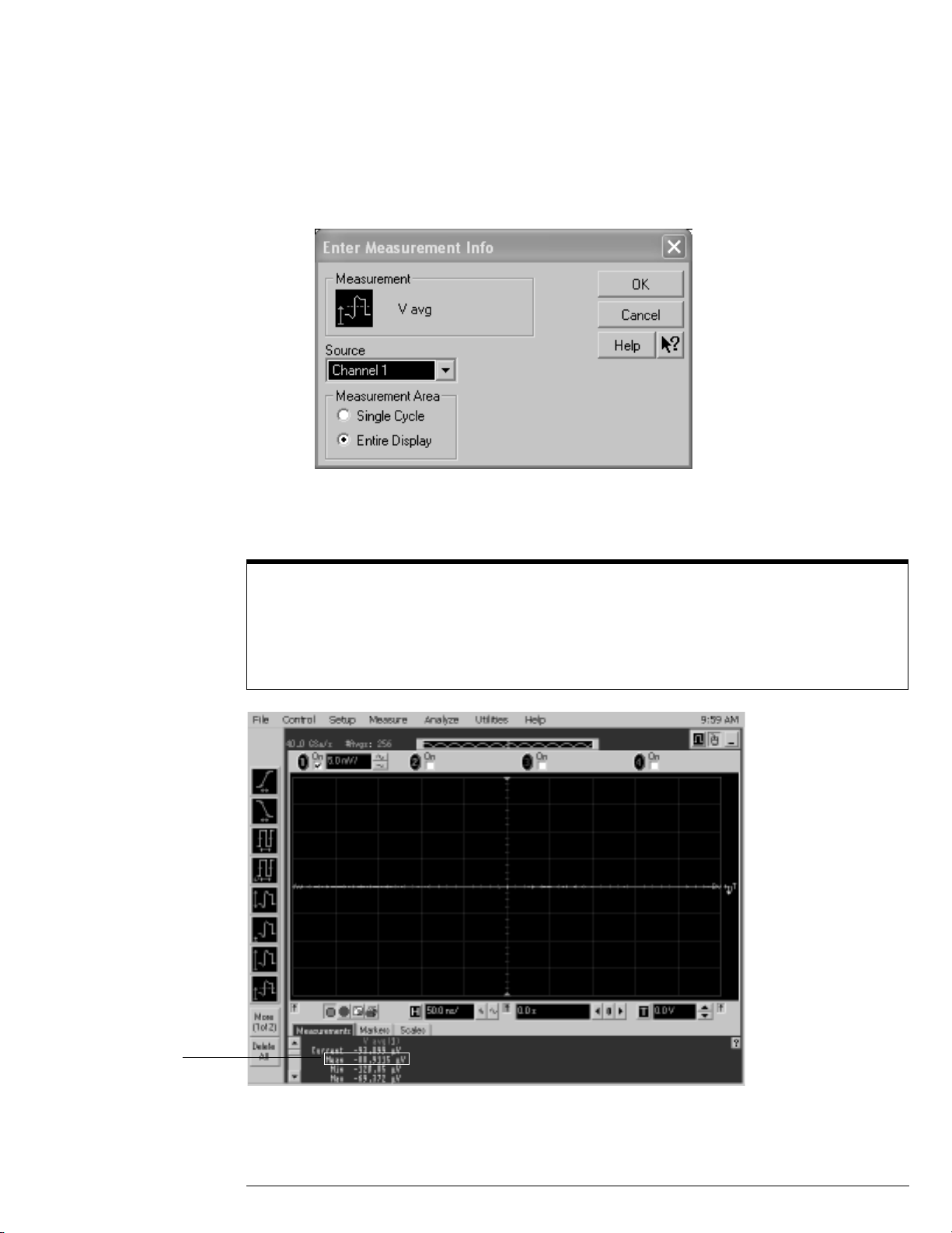
c When the Enter Measurement Info window is displayed, ensure that the V avg function
is set up as follows and then click OK:
Source = Channel 1
Measurement Area = Entire Display
4
Press the Clear Display key on the scope and wait for the #Avgs value (top left corner
of screen) to return to 256. Record the scope's mean V avg reading in the Zero Error
Test section of the Performance Test Record.
Notes
• For all scope readings in this pro cedure , use the mean value i n the Measu rement s displ ay area at the
bottom of the screen.
• If a question mark is display ed in f ront of any o f the v alu es at t he bot tom o f the s creen, pr ess the Clea r
Display key on the scope, wait for the #Avg s value to ret urn to 256 and then record the scope readi ng.
Record the
mean reading
5 Change the vertical sensitivity of channel 1 to 10 mV/div, press the Clear Display key,
wait for the #Avgs value (top left corner of screen) to return to 256 and then record the
scope V avg reading in the Zero Error Test section of the Performance Test Record.
3–7
Page 50

Chapter 3: Testing Performance
Offset Accuracy Test
Repeat step 5 for the remaining vertical sensitivities for channel 1 in the Zero Error
6
Test section of the Performance Test Record.
7 Press Default Setup, then turn off channel 1 and turn channel 2 display on.
8 Configure the scope to measure V avg on Channel 2 as follows:
a Pull down the Utilities menu and select Acquisition. When the Acquisition Setup window
is displayed, enable averaging and set the # of averages to 256.
b Change the vertical sensitivity of channel 2 to 5 mV/div.
c Click the V avg measurement icon on the left side of the screen.
d When the Enter Measurement Info window is displayed, ensure that the Vavg function
is set up as follows and then click OK:
Source = Channel 2
Measurement area = Entire Display
9
Press the Clear Display key on the scope, wait for the #Avgs value to return to 256 and
then record the scope’s mean V avg reading in the Zero Error Test section of the
Performance Test Record.
10 Repeat step 9 for the remaining vertical sensitivities for channel 2 in the Zero Error
section of the Performance Test Record.
11 Repeat steps 7 through 10 for channels 3 and 4.
3–8
Page 51

Offset Gain Test
12
Make the connections to scope channel 1 as shown below.
Connections
Chapter 3: Testing Performance
Offset Accuracy Test
Notes:
• Where it is used, it i s import ant t o connect the B NC Tee adapt er direct l y to the scop e channel in put to
minimize ground potential differences between the scope and the test oscilloscopes and to ensure
that the DMM measures the input voltage to t he scope chann el as accuratel y as possibl e. Difference s
in ground potential can be a significant source of measurement error, particularly at high scope
sensitivities.
• It also helps to reduce ground potential differences if the scope and the external test os cilloscopes
are connected to the same AC supply circuit.
• A fairly large number of aver ages are used in the scope measurements of this section to reduce
measurement noise and to reduce the measurement error due to resolution.
Set up the DMM to perform DC voltage measurements.
13
14 Configure the scope to measure V avg on Channel 1 as follows:
a Press Default Setup.
b Pull down the Utilities menu and select Acquisition. When the Acquisition Setup window
is displayed, enable averaging and set the # of averages to 256.
c Change the vertical sensitivity of channel 1 to 5 mV/div.
d Click the V avg measurement icon on the left side of the screen.
e When the Enter Measurement Info window is displayed, ensure that the V avg function
is set up as follows and then click OK:
Source = Channel 1
Measurement area = Entire Display
3–9
Page 52

Channel 1
setu p i c on
Chapter 3: Testing Performance
Offset Accuracy Test
Set the channel 1 offset value to 400.0 mV. This can be done either using the front panel
15
control or:
a Pull down the Setup menu and select Channel 1 or click the Channel 1 setup icon.
b Click the Offset control arrows to change the offset value or click on the offset value
and enter 400.0 mV in the dialog box.
c Enter 400.0 mV in the Enter Offset dialog box.
16
Set the Aux Out voltage (V
a Pull down the Utilities menu and select Calibration.
b Change the Aux Output function to DC (top left corner).
c Set the Level to 400.0 mV.
d Click on Close.
17
Press the Clear Display key on the scope, wait for the #Avgs value (top left corner of
Aux Out
screen) to return to 256 and then record the DMM voltage reading as V
scope Vavg reading as V
Scope+
) to +400.0 mV as follows:
and the
DMM+
in the Offset Gain Test section of the Performance Test
Record.
3–10
Page 53

Chapter 3: Testing Performance
Offset Accuracy Test
Change the channel 1 offset value to -400.0 mV.
18
19 Set the Aux Out voltage to -400.0 mV.
20 Press the Clear Display key on the scope, wait for the #Avgs value (top left corner of
screen) to return to 256 and then record the DMM voltage reading as V
scope Vavg reading as V
in the Offset Gain Test section of the Performance Test
Scope-
DMM-
and the
Record.
21 Change the channel 1 offset value to 0 mV.
22 Set the Aux Out voltage to 0 mV.
23 Press the Clear Display key on the scope, wait for the #Avgs value (top left corner of
screen) to return to 256 and then record the DMM voltage reading as V
scope Vavg reading as V
in the Offset Gain Test section of the Performance Test
Scope0
DMM0
and the
Record.
24 Calculate the offset gain error using the following expressions and record the value in
the Offset Gain Test section of the Performance Test Record. The offset gain error is
the greater (maximum magnitude) of either:
V
------------------------------------------
V
scope+
DMM+
– V
– V
scope0
DMM0
1–
100
or
V
-----------------------------------------
V
scopeDMM-
– V
– V
scope0
DMM0
1–
100
25 Repeat steps 15 to 21 for the remaining channel 1 vertical sensitivities in the Offset
Gain Test section of the Performance Test Record. For each measurement, set both
the Aux Out voltage (V
Aux Out
value and then to the negative V
) and the Channel offset voltage to the positive V
Aux Out
value in the "V
Aux Out
Setting" column of the
Aux Out
Offset Gain Test table in the Performance Test Record for each of the vertical
sensitivities.
26 Move the Tee connector to the next channel input and repeat steps 18 to 22 for the
channels 2 to 4.
3–11
Page 54

Chapter 3: Testing Performance
DC Gain Accuracy Test
DC Gain Accuracy Test
CAUTION Ensure that the input voltage to the oscilloscope never exceeds ±5 V.
Specifications
DC Gain Accura cy ±2% of full scale at full resolution channel scale
Full scale is defined as 8 vertical divisions. Magnification is used below 5 mV/div. Below 5 mV
full scale is defined as 40 mV. The major scale settings are 5 mV, 10 mV, 20 mV,
50 mV, 100 mV, 200 mV, 500 mV and 1 V.
Equipment Required
Description Critical Specifications Recommended
Digital Multimeter DC voltage measur ement a ccurac y better than ±0. 1% of r eading Agilent 34401A or
Cable Assembly
(2 required)
Adapter BNC Tee (m)(f)(f) Agilent 1250-0781
Adapter BNC (f) to dual banana Agilent 1251-2277
50Ω character istic impedance, BNC (m) connect ors Agil ent 8120-1840
Model/
Part Numbers
Agilent 3458A
Procedure
Disconnect all cables from the scope channel inputs.
1
2 Press Default Setup, then configure the scope as follows:
a Pull down the Setup menu and select Acquisition.
3–12
Page 55

Chapter 3: Testing Performance
DC Gain Accuracy Test
b When the Acquisition Setup window is displayed, enable averaging and set the # of
averages to 256 as shown below.
3
Set the Aux Out voltage (V
a Pull down the Utilities menu and select Calibration.
b Change the Aux Output function to DC (top left corner).
c Set the Level to 15 mV.
d Click on Close.
4
Set the channel 1 vertical sensitivity value to 5 mV/div. This can be done either using
Aux Out
) to +15 mV as follows:
the front panel control or:
a Pull down the Setup menu and select Channel 1 or click the Channel 1 setup icon.
b Change the vertical sensitivity of channel 1 to 5 mV/div.
3–13
Page 56
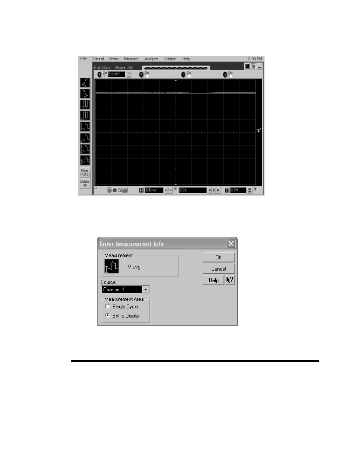
V avg
measurement
Chapter 3: Testing Performance
DC Gain Accuracy Test
c Select the Vavg measurement as shown below.
d When the Enter Measurement Info window is displayed, ensure that the V avg function
is set up as follows and then click OK:
Source = Channel 1
Measurement Area = Entire Display
5
Press the Clear Display key on the scope, wait for the #Avgs value (top left corner of
screen) to return to 256 and then record the scope's mean V avg reading in the DC Gain
Test page 3-26 section of the Performance Test Record.
Notes
• For all scope readings in this pro cedure , use the mean value i n the Measu rement s displ ay area at the
bottom of the screen.
• If a question mark is display ed in f ront of any o f the v alu es at t he bot tom o f the s creen, press the Clea r
Display key on the scope, wait for the #Avg s value to return to 25 6 and then record the sco pe reading.
3–14
Page 57

Record the
mean reading
Chapter 3: Testing Performance
DC Gain Accuracy Test
Change the the Aux Out voltage to -15 mV.
6
7 Press the Clear Display key on the scope, wait for the #Avgs value to return to 256 and
then record the DMM voltage reading and the scope V avg reading in the DC Gain Test
section of the Performance Test Record.
8 Repeat step 7 for the remaining vertical sensitivities for channel 1 in the DC Gain Test
section of the Performance Test Record.
9 Press Default Setup, then turn off channel 1 and turn channel 2 display on.
10 Set the Aux Out voltage (V
11 Configure the scope to measure V avg on Channel 2.
a Pull down the Utilities menu and select Acquisition. When the Acquisition Setup window
is displayed, enable averaging and set the # of averages to 256.
b Change the vertical sensitivity of channel 2 to 5 mV/div.
c Click the V avg measurement icon on the left side of the screen.
d When the Enter Measurement Info window is displayed, ensure that the Vavg function
is set up as follows and then click OK:
Source = Channel 2
Measurement area = Entire Display
12
Press the Clear Display key on the scope, wait for the #Avgs value to return to 256 and
Aux Out
) to +15 mV as follows:
then record the DMM voltage reading and the scope V avg reading in the DC Gain Test
section of the Performance Test Record.
13 Repeat step 12 for the remaining vertical sensitivities for channel 2 in the DC Gain
section of the Performance Test Record.
14 Repeat steps 9 through 13 for channels 3 and 4.
3–15
Page 58

Chapter 3: Testing Performance
DC Gain Accuracy Test
Calculate the offset gain using the following expression and record this value in the
15
DC Gain Test section of the Performance Test Record.
For vertical sensitivities of less than 1 volt use the following equation:
DCGainError =
∆V
out
--------------
∆V
V
scope+
=
----------------------------------------- 1–
V
in
DMM+
– V
– V
scopeDMM-
For vertical sensitivity = 1 V use the following equation:
DCGainError =
∆V
out
--------------
∆V
V
scope+
=
----------------------------------------- 1–
V
in
DMM+
– V
– V
scopeDMM-
0.75⋅
0.6⋅
3–16
Page 59

Analog Bandwidth - Maximum Frequency Check
Analog Bandwidth - Maximum Frequency Check
CAUTION Ensure that the input voltage to the oscilloscope never exceeds ±5 V.
Specification
Analog Bandwidth (-3 dB)
DSO81304A 12.0 GHz
DSO81204A 12.0 GHz
DSO81004A 10.0 GHz
DSO80804A 8.0 GHz
Equipment Required
Chapter 3: Testing Performance
Description Critical Specifications Recommended Model/
Microwave CW
Generator
Power Splitter 2 Resistor Power Splitter
Power Meter Agilent E-series w ith power sensor compatibility Agilent E4418B or E4419B
Power Sensor Maximum Frequency ≥ 14 GHz
Microwave Cab le 50Ω Characteristic Impedance
SMA Adapters 3.5 mm (m) to 3.5 mm ( m ) SM A Agilent E2655-83202
SMA to BNC Adapter 3.5 mm (f) SMA to Precision BNC (No Substitute) Agilent 54855-67604
Maximum Frequency ≥ 14 GHz
Power range: -20 dBm to +16 dBm into 50Ω
Output resistance = 50Ω
Max Frequency ≥18 GHz
Power range: -24 dBm to +16 dB m
3.5 mm (m) to 3.5 mm (m) SMA connector s
Max Frequency ≥18 GHz
Part Numbers
Agilent E8257D with Opt 520
Agilent 11667B
Agilent E4413A
Agilent 8120-4948
3–17
Page 60

Chapter 3: Testing Performance
Analog Bandwidth - Maximum Frequency Check
Connections
Power meter
E4418A or E4419A
Power sensor
cable
Microwave CW
Generator E8257D
Power splitter
11667B
SMA to BNC adapter
SMA adapter
Power sensor
E4413A
Microwave cable
Notes
• Connect output 1 of the 11667B splitter to the scope Channel n input directly using th e 54855-67604
adapter, without any additional cabling or adapters.
• Connect the power sensor directly to output 2 of the power splitter without any additional cabling or
adapters.
• Minimize the use of other adapters.
• Ensure that SMA and 3.5 mm connectors are tightened properly:
8 in-lbs (90 N-cm) for 3.5 mm
5 in-lbs (56 N-cm) for SMA
Procedure
Preset the power meter.
1
2 Ensure that the power sensor is disconnected from any source and zero the meter.
3 Connect the power sensor to the power meter's Power Ref connector and calibrate the
meter.
4 Make the connections to scope channel 1 as shown in the connection diagram above.
5 Set up the Power Meter to display measurements in units of Watts.
6 Press Default Setup, then configure the scope as follows:
a Ensure Channel 1 is displayed and all other channels are turned off.
b Set the vertical sensitivity of channel 1 to 5 mV/div.
3–18
Page 61

Chapter 3: Testing Performance
Analog Bandwidth - Maximum Frequency Check
c Set the horizontal scale to 16 ns/div (to display 8 cycles of a 50 MHz waveform).
Click here and enter 16E-9
d Pull down the Setup menu, select Acquisition and then set up the acquisition parameters
as follows:
Memory Depth = Automatic
Sampling rate = Maximum (40 GSa/s)
Sin(x)/x Interpolation filter enabled
Averaging = Disabled
e Pull down the Measure menu, select Voltage and then select V rms.
3–19
Page 62

Chapter 3: Testing Performance
Analog Bandwidth - Maximum Frequency Check
f When the RMS voltage measurement setup window is displayed, configure this
measurement as follows:
Source = Channel 1
Measurement Area = Entire Display
RMS Type = AC
7
Set the generator to apply a 50 MHz sine wave with a peak-to-peak amplitude of about
4 divisions.
• Use the following table to determine the approximate required signal amplitude.
The amplitude values in the table below are not absolutely required. If your generator is
unable to produce the recommended amplitude, then set the generator to the highest
value that does not produce a vertically clipped signal on the scope.
Table 3-1. Nominal Generator Amplitude Settings
Scope
Vertical Sensitivity
5 mV/div 0.02 -30
10 mV/div 0.04 -24
20 mV/div 0.08 -18
50 mV/div 0.20 -10
100 mV/div 0.40 -4
200 mV/div 0.80 +2
500 mV/div 2.0 +10
1 V/div 4.0 +16
8
Measure the input power to the scope channel and convert this measurement to Volts
Gener a tor Signal
Amplitude (Vp-p)
Generator Si gnal
Amplitude (dBm)
RMS using the expression:
V
in
For example, if the power meter reading is 4.0 µW, then Vin = (4.0*10-6 * 50Ω)
Record the RMS voltage in the Analog Bandwidth - Maximum Frequency Check section of the
Performance Test Record (Vin @ 50 MHz).
P
meas
50Ω×=
1/2
= 14.1 mVrms.
3–20
Page 63

Chapter 3: Testing Performance
Analog Bandwidth - Maximum Frequency Check
Press the Clear Display key on the scope and record the scope V rms reading in the
9
Analog Bandwidth - Maximum Frequency Check section of the Performance Test
Record (Vout @ 50 MHz). For all scope readings in this procedure, use the mean value
in the Measurements display area at the bottom of the screen.
Notes
• For all scope readings in this pro cedure , use the mean value i n the Measu rement s displ ay area at the
bottom of the screen.
• If a question mark is display ed in f ront of any o f the v alu es at t he bot tom o f the s creen, pr ess the Clea r
Display key on the scope, wait for the #Avgs val ue to return to 16 and then record the scope reading.
Record the
mean reading
10 Calculate the reference gain as follows:
V
Gain
50 MHz
Record this value in the Calculated Gain @50 MHz column in the Analog Bandwidth - Maximum
Frequency Check section of the Performance Test Record.
out @50 MHz
-------------------------------=
V
in @50 MHz
3–21
Page 64

Chapter 3: Testing Performance
Analog Bandwidth - Maximum Frequency Check
Change the generator frequency to the maximum value for the model being tested as
11
shown in the table below. It is not necessary to adjust the signal amplitude at this point
in the procedure.
Setting Model
DSO80804A DSO81004A DSO81204A DSO81304A
Maximum Frequency 8.0 GHz 10.0 GHz 12.0 GHz 12.0 GHz
Scope Time Base Setting 100 ps/div 100 ps/div 100 ps/div 100 ps/div
12 Change the scope time base to the value for the model under test in the table above.
Click here and enter time
base valu e from table
13 Measure the input power to the scope channel at the maximum frequency and convert
this measurement to Volts RMS using the expression:
V
in
For example, if the power meter reading is 4.0 µW, then Vin = (4.0*10-6 * 50Ω)
Record the RMS voltage in the Analog Bandwidth - Maximum Frequency Check section of the
Performance Test Record (Vin @ Max Freq).
14
Press the Clear Display key on the scope and record the scope V rms reading in the
P
meas
50Ω×=
1/2
= 14.1 mVrms.
Analog Bandwidth - Maximum Frequency Check section of the Performance Test
Record (Vout @ Max Freq).
15 Calculate the gain at the maximum frequency using the expression:
V
()V
out Max Freq
Gain
Max Freq
For example, if (Vout @ Max Frequency) = 13.825 mV, (Vin @ Max Frequency) = 13.461 mV
and Gain @ 50MHz = 1.0023, then:
Gain
Max Fre q
Record this value in the Calculated Gain @Max Freq column in the Analog Bandwidth - Maximum
Frequency Check section of the Performance Test Record. To pass this test, this value must be
greater than -3.0 dB.
20 log
=
20 log
10
------------------------------------------------------------------------------
10
13.825 mV 13.461 mV ⁄
-------------------------------------------------------------
Gain
1.0023
()⁄
in Max Freq
50 MHz
0.212 dB==
3–22
Page 65

Change the scope set up as follows:
16
a Change the channel vertical sensitivity to 10 mV/div.
b Reset the horizontal scale to 16 ns/div (to display 8 cycles of a 50 MHz waveform).
17 Change the generator output as follows:
a Reset the generator frequency to 50 MHz.
b Change the amplitude to the value suggested for this sensitivity in Table 3-1.
18
Repeat steps 8, 9, and 10 to measure the reference gain at 50 MHz for this sensitivity.
19 Repeat steps 11, 12, 13, and 14 to measure the gain at maximum frequency for this
sensitivity.
20 Repeat steps 15 to 19 to complete measuring gains for remaining sensitivities for
channel 1 in the Analog Bandwidth - Maximum Frequency Check section of the
Performance Test Record.
21 Move the splitter to channel 2 and change the scope configuration as follows:
• Ensure Channel 2 is displayed and all other channels are turned off.
• Set the vertical sensitivity of channel 2 to 5 mV/div.
• Set the horizontal scale to 16 ns/div (to display 8 cycles of a 50 MHz waveform).
• Right click on the V rms measurement at the bottom of the screen. When the RMS voltage
measurement setup window is displayed, change the source from Channel 1 to Channel 2.
22
Repeat steps 7 to 20 to complete measuring gains for channel 2.
23 Move the splitter to channel 3 and change the scope configuration as follows:
a Ensure Channel 3 is displayed and all other channels are turned off.
b Set the vertical sensitivity of channel 3 to 5 mV/div.
c Set the horizontal scale to 16 ns/div (to display 8 cycles of a 50 MHz waveform).
d Click on the V rms measurement at the bottom of the screen and select Customize. When
the V rms setup window is displayed, change the source from Channel 2 to Channel 3.
24
Repeat steps 7 to 20 to complete measuring gains for channel 3.
25 Move the splitter to channel 4 and change the scope configuration as follows.
a Ensure Channel 4 is displayed and all other channels are turned off.
b Set the vertical sensitivity of channel 4 to 5 mV/div.
c Set the horizontal scale to 16 ns/div (to display 8 cycles of a 50 MHz waveform).
d Click on the V rms measurement at the bottom of the screen. When the V rms setup
window is displayed, change the source from Channel 3 to Channel 4.
26
Repeat steps 7 to 20 to complete measuring gains for channel 4.
3–23
Page 66

Chapter 3: Testing Performance
Performance Test Record
Performance Test Record
Offset Performance Test
Zero Error Test
Vertical
Sensitivity
5 mV/div -1.4 mV to +1.4 mV
10 mV/div -1.8 mV to +1.8 mV
20 mV/div -2.6 mV to +2.6 mV
50 mV/div -5.0 mV to +5.0 mV
100 mV/div -9.0 mV to +9.0 mV
200 mV/div -17.0 mV to +17.0 mV
500 mV/div -41.0 mV to +41.0 mV
1 V/div -81.0 mV to +81.0 mV
Test Limits Channel 1 Channel 2 Channel 3 Channel 4
3–24
Page 67

Chapter 3: Testing Performance
Performance Test Record
Offset Gain Test
Vertical
Sensitivity
V
Aux Out
Setting
V
DMM+
Channel 1
5 mV/div ±400 mV ±2 %
10 mV/div ±400 mV ±2 %
20 mV/div ±400 mV ±2 %
50 mV/div ±900 mV ±2 %
100 mV/div ±1.6 V ±2 %
200 mV/div ±2.4 V ±2 %
500 mV/div ±2.4 V ±2 %
1 V/div ±2.4 V ±2 %
Channel 2
5 mV/div ±400 mV ±2 %
10 mV/div ±400 mV ±2 %
20 mV/div ±400 mV ±2 %
50 mV/div ±900 mV ±2 %
100 mV/div ±1.6 V ±2 %
200 mV/div ±2.4 V ±2 %
500 mV/div ±2.4 V ±2 %
1 V/div ±2.4 V ±2 %
Channel 3
5 mV/div ±400 mV ±2 %
10 mV/div ±400 mV ±2 %
20 mV/div ±400 mV ±2 %
50 mV/div ±900 mV ±2 %
100 mV/div ±1.6 V ±2 %
200 mV/div ±2.4 V ±2 %
500 mV/div ±2.4 V ±2 %
1 V/div ±2.4 V ±2 %
Channel 4
5 mV/div ±400 mV ±2 %
10 mV/div ±400 mV ±2 %
20 mV/div ±400 mV ±2 %
50 mV/div ±900 mV ±2 %
100 mV/div ±1.6 V ±2 %
200 mV/div ±2.4 V ±2 %
500 mV/div ±2.4 V ±2 %
1 V/div ±2.4 V ±2 %
V
DMM-
V
DMM0
V
Scope+
V
Scope-
V
Scope0
Calculated
Offset Gain
Error
Offset Gain
Error Test
Limits
3–25
Page 68

Chapter 3: Testing Performance
Performance Test Record
DC Gain Test
Vertical
Sensitivity
V
Aux Out
Setting
V
DMM+
V
DMM-
Channel 1
5 mV/div ±15 mV ±2 %
10 mV/div ±30 mV ±2 %
20 mV/div ±60 mV ±2 %
50 mV/div ±150 mV ±2 %
100 mV/div ±300 mV ±2 %
200 mV/div ±600 mV ±2 %
500 mV/div ±1.5 V ±2 %
1 V/div ±2.4 V ±2 %
Channel 2
5 mV/div ±15 mV ±2 %
10 mV/div ±30 mV ±2 %
20 mV/div ±60 mV ±2 %
50 mV/div ±150 mV ±2 %
100 mV/div ±300 mV ±2 %
200 mV/div ±600 mV ±2 %
500 mV/div ±1.5 V ±2 %
1 V/div ±2.4 V ±2 %
Channel 3
5 mV/div ±15 mV ±2 %
10 mV/div ±30 mV ±2 %
20 mV/div ±60 mV ±2 %
50 mV/div ±150 mV ±2 %
100 mV/div ±300 mV ±2 %
200 mV/div ±600 mV ±2 %
500 mV/div ±1.5 V ±2 %
1 V/div ±2.4 V ±2 %
Channel 4
5 mV/div ±15 mV ±2 %
10 mV/div ±30 mV ±2 %
20 mV/div ±60 mV ±2 %
50 mV/div ±150 mV ±2 %
100 mV/div ±300 mV ±2 %
200 mV/div ±600 mV ±2 %
500 mV/div ±1.5 V ±2 %
1 V/div ±2.4 V ±2 %
V
Scope+
V
Scope-
Calculated
DC Gain
Error
DC Gain Error
Test Limits
3–26
Page 69

Analog Bandwi dth - Maximum Frequency Check
Max frequenc y: DSO80804A = 8.0 GHz , DSO81004A = 10.0 GHz, DSO81204A = 12.0 GHz, DSO81304A = 12.0 GHz
Measurement
Vertical
Sensitivity
Channel 1
5 mV/div
10 mV/div
20 mV/div
50 mV/div
100 mV/div
200 mV/div
500 mV/div
1 V/div
Channel 2
5 mV/div
10 mV/div
20 mV/div
50 mV/div
100 mV/div
200 mV/div
500 mV/div
1 V/div
Channel 3
5 mV/div
10 mV/div
20 mV/div
50 mV/div
100 mV/div
200 mV/div
500 mV/div
1 V/div
Channel 4
5 mV/div
10 mV/div
20 mV/div
50 mV/div
100 mV/div
200 mV/div
500 mV/div
1 V/div
Vin @ 50 MHz Vout @ 50
MHz
Calculated
Gain @ 50
MHz
(Test Limit =
greater t han 3 dB)
Vin @ Max
Freq
Chapter 3: Testing Performance
Performance Test Record
Vout @ Max
Freq
Calculated
Gain @ Max
Freq
(Test Limit =
greater t han 3 dB)
3–27
Page 70

Chapter 3: Testing Performance
Performance Test Record
3–28
Page 71

4
To run the self calibration 4-3
Calibration
Page 72

Calibration
This chapter provides self calibration procedures for the oscilloscope.
4–2
Page 73

Chapter 4: Cali bration
To run the self calibration
To run the self calibration
Let the Oscilloscope Warm Up Before Adjusting
Warm up the oscilloscope fo r 30 minute s before sta rti ng cali bratio n procedur e. Failure to al low warm up
may result in inaccura te calibration.
The self calibration uses signals generated in the oscilloscope to calibrate channel sensitivity,
offsets, and trigger parameters. You should run the self calibration
• yearly, or according to your periodic needs,
• when you replace the acquisition assembly or acquisition hybrids,
• when you replace the hard drive or any other assembly,
• when the oscilloscope’s operating temperature (after the 30 minute warm-up period) is more
than ±5 °C different from that of the last calibration.
Equipment Required
Equipment Critical Specificati ons Agi lent Part Number
Adapters (2 supplied with oscilloscope) 3.5 mm (f) t o precisi on BNC No s ubstit ute Agilent 54855-676 04
Cable Assembly 50
Cable Assembly (supplie d w ith oscilloscope) No substitute Agilent 54855-61620
10 MHz Signal Source (required for time scale
calibration)
* Requires time base calibration once every 6 months. Should not be powered off for more than 24 hours after time base calibration.
** Require s link to GPS
Ω char acter istic imped ance BNC (m)
connectors ~ 36 inches (91 cm) to 48
inches (122 cm) long
Frequency accurac y be tter tha n 0.4 pp m Agilent 53131A with Opt. 010*
Agilent 8120-1840
Self calibration
Calibration time
It will take approxi mately 1 hour to run the sel f calibra tion on the oscil loscope, incl uding the ti me required
to change cables from channel to channel.
Let the Oscilloscope Warm Up Before Running the Self Calibration.
1
The self calibration should only be done after the oscilloscope has run for 30 minutes at ambient
temperature with the cover installed. Calibration of an oscilloscope that has not warmed up may
result in an inaccurate calibration.
2
Pull down the Utilities menu and Select Calibration.
3 Click the check box to clear the Cal Memory Protect condition.
You cannot run self calibration if this box is checked. See Figure 4-1.
4–3
Page 74

Figure 4-1
Clear this check
box before starting
calibration
Click here to start
calibration
Chapter 4: Cali bration
To run the self calibration
Calibrati on Dialog
4
Click Start, then follow the instructions on the screen.
The routine will ask you to do the following things in sequence:
a Decide if you wish to perform the Time Scale Calibration. Your choices are:
• Std - Time scale calibration will not be performed. Time scale calibration factors from
the previous time scale calibration will be used and the 10 MHz reference signal will not
be required. The remaining calibration procedure will continue.
• Std + Time - Performs the time scale calibration. This option requires you to connect a
10 MHz reference signal to channel 1 that meets the following specifications. Failure to
use a reference signal that meets this specification will result in an inaccurate calibration.
Frequency: 10 MHz ±0.4 ppm = 10 MHz ±4 Hz
Amplitude: 0.2 Vpeak-to-peak to 5.0 Vpeak-to-peak
Wave shape: Sine or Square
• Std + Dflt - Factory time scale calibration factors will be used. The 10 MHz reference
signal will not be required. The remaining calibration procedure will continue.
b Disconnect everything from all inputs and Aux Out.
c Connect the cal cable from Aux Out to channel 1.
You must use the 54855-61620 cable assembly with two 54855-67604 adapters. Failure
to use the appropriate cal cable will result in an inaccurate calibration.
d Connect the cal cable from Aux Out to each of the channel inputs as requested.
e Connect the 50 Ω BNC cable from the Aux Out to the Aux Trig In on the rear panel of
the oscilloscope.
f A Passed/Failed indication is displayed for each calibration section. If any section fails,
check the calibration cables and run the oscilloscope Self Test in the Utilities menu.
5
After the calibration procedure is completed, click Close.
4–4
Page 75

5
Safety page 5-2
Tools Required page 5-2
ESD Precautions page 5-2
Keystroke Conventions page 5-2
Default Setup page 5-3
To install the fan safety shield page 5-3
To troubleshoot the oscilloscope page 5-4
Primary Trouble Isolation page 5-5
Display Trouble Isolation page 5-19
POST Code Listing page 5-32
Power Supply Trouble Isolation page 5-12
To check the keyboard; Trouble Isolation Procedure page 5-36
To check the LEDs page 5-37
Software Revisions page 5-38
To check probe power outputs page 5-39
To check the display board video signals page 5-40
To check the backlight inverter voltages page 5-41
Troubleshooting
Page 76

Troubleshooting
This section provides troubleshooting information for the Agilent Technologies
DSO80000 series oscilloscopes. The service strategy of this oscilloscope is replacement
of defective assemblies.
Safety
Read the Safety Summary at the front of this manual before servicing the oscilloscope.
Before performing any procedure, review it for cautions and warnings.
WARNING SHOCK HAZARD!
Maintenance should be performed by trained service personnel aware of the hazards involved
(for example, fire and electric shock). Lack of training and awareness of the hazards could result
in electrical shock. When maintenance can be performed without power applied, the power cord
should be removed from the oscilloscope.
WARNING INJURY CAN RESULT!
Use caution when working around the cooling fan with the cover removed from the oscilloscope.
The cooling fan blades are exposed on one side and can be hazardous. Install the optional fan
safety shield (Agilent Technologies P/N 54810-00601) to protect your fingers from the fan blades.
Tools Required
You will need basic electronic troubleshooting tools, including a digital multimeter,
external Atx supply or loopback connector, external monitor, and a 100 MHz
oscilloscope. Performance verification tests have more stringent requirements. See
chapter 1 for the list of recommended test equipment.
If you need to remove and replace assemblies, you will need some of the hand tools listed
in chapter 6, “Replacing Assemblies.”
ESD Precautions
When using any of the procedures in this chapter, you should use proper ESD
precautions. As a minimum, you should place the oscilloscope on a properly grounded
ESD mat and wear a properly grounded ESD wrist strap.
Keystroke Conventions
To guide you while setting up the oscilloscope, the following conventions are used to
represent keystrokes and other interactions with the oscilloscope:
• When you need to issue a command through the graphical interface, the command
will be phrased like this: “Select <command> from the <menu name> menu.”
• When you need to click on an object on the graphical interface, the instructions will
be phrased something like this: “Click the OK button.”
• When you need to press a key, the instructions will be phrased something like this:
“Press the Run key.”
5–2
Page 77

Figure 5-1
Chapter 5: Troubleshooting
To install the fan safety shield
Default Setup
A Default Setup is provided to assure the oscilloscope setup is in a known default state.
The default setup prevents previous setups from interfering with the next test. It also
simplifies the oscilloscope setup procedure. Use the default setup when a procedure
requires it.
• Press the Default Setup key to set the oscilloscope to the default state.
To install the fan safety shield
1 Disconnect the oscilloscope power cord and remove the cover.
If necessary, refer to the procedures in chapter 6 "Replacing Assemblies".
Clip the fan safety shield over the outside of the oscilloscope chassis next to the fans.
2
See Figure 5-1.
Installing the Fa n Safety Shield
5–3
Page 78

Chapter 5: Troubleshooting
To troubleshoot the oscilloscope
To troubleshoot the oscilloscope
The troubleshooting procedure is used to isolate problems to a faulty assembly. When you find
the faulty assembly, use the disassembly and assembly procedures in chapter 6 to replace the
assembly.
The primary procedural tool in this section is the flowchart. The flowchart contains the entire
troubleshooting path from a failed oscilloscope to a working one, and will direct you in an orderly
manner through the possible failure symptoms. Reference letters on the flowcharts point to
procedural steps that explain the brief instructions in the chart.
If you are unfamiliar with this oscilloscope, start with the Primary Trouble Isolation Flowchart.
5–4
Page 79

Chapter 5: Troubleshooting
Primary Trouble Isolation
Primary Trouble Isolation
A letter is assigned to boxes in the flowchart. The letter corresponds to a specific section in the
reference text. Be sure to use the flowchart itself for your troubleshooting path.
5–5
Page 80

Chapter 5: Troubleshooting
Primary Trouble Isolation
Primary Trouble Isolation Flowchart
Primary Trouble Isolation
Turn power on
Go to 'Power Supply
Trouble Isolation'
Go to 'Displ ay Trouble
Isolation'
Replace
motherboard.
No
Yes
No
A
B
Check processor
Does
power lig ht
illuminate?
Yes
Check di splay
On
screen display
problems?
No
temperature?
Is
temperature
OK?
5–6
Replace fan.
Yes
C
Check for fan fail
Yes
message.
Does
fan fail ?
No
PT
Page 81

Primary Trouble Isolation Flowchart (continued)
PT
D
Run scope self tests.
Chapter 5: Troubleshooting
Primary Trouble Isolation
E
Check front panel
knob and key test
Does
self test
pass?
Yes
response.
Do
OK?
Yes
Does
LED test
OK?
No
No
Go to 'Acquisition
Trouble Isolation'
Go to 'Front Panel
Trouble Isolation'
F
Check calibration
self calibration test
G
System works; do
performance tests
Yes
Does
pass?
Yes
End
No
Go to 'Acquisition
Trouble Isolation'
5–7
Page 82

Figure 5-1
Chapter 5: Troubleshooting
Primary Trouble Isolation
Check the display.
A
1 Press the Default Setup key.
Power-on Displ ay Default
The display on the screen should be similar to . If there is no display on the oscilloscope flat-panel
display after power-up, go to the No Display Trouble Isolation Flowchart otherwise go to step B.
5–8
Page 83

Chapter 5: Troubleshooting
Primary Trouble Isolation
Check the processor temperature. If the processor temperature is over 70 °C, the
B
motherboard will turn on an audible alarm. If the alarm can be heard:
1 Reboot the oscilloscope.
2 Press del key when the splash screen is seen.
3 Scroll down to PC Health Status and press the Enter key.
4 Check that the Current CPU Temperature is around 45 °C.
If the processor temperature is hot, check the following:
1 Check that the processor’s heatsink is properly attached.
2 Check that the heatsink fan cable is connected to the motherboard.
If the above steps do not solve the problem then replace the motherboard assembly.
C
Check for the fan failure message. When the oscilloscope application loads, it will
check that the fans are running. If a fan is not running, a fan failure message will appear.
If more than one fan has failed, the oscilloscope will shut down.
D Run oscilloscope self-tests.
1 Select Self Test from the Utilities menu.
2 Select Scope Self Tests from the Self Test drop down list box.
3 Click the Start Test button and follow the instructions on the screen.
If any of the selftests fail, go to the Acquisition Trouble Isolation troubleshooting flowchart later
in this chapter for further troubleshooting. Otherwise, go to step E.
E
Check the front panel response by running the knob, key, and LED self tests.
Use this procedure to verify correct keyboard operation.
1 Select Self Test from the Utilities menu.
2 Select Knob and Key from the Self Test drop down list box, then click Start.
A new window appears with a symbolic representation of the keyboard. See Figure 5-2.
Figure 5-2
When you push a key
or turn a knob in both
directions, the
correspon ding symbol
on this screen turns
green.
Knob and Key Self Test Screen
5–9
Page 84

Figure 5-3
Chapter 5: Troubleshooting
Primary Trouble Isolation
3 Push each key on the keyboard until you have pushed all keys.
When you push a key, the corresponding key symbol on the display should change from red to
green.
4 Turn each knob in both directions until you have turned all knobs.
When you turn a knob in one direction, the corresponding knob symbol on the display should
change from red to yellow. When you then turn the knob in the other direction, the knob symbol
should change from yellow to green.
5
When you are finished, click Close.
If any of the knobs or keys do not work, go to To check the keyboard; Trouble Isolation Procedure
page 5-36.
Use the following procedure to test the front-panel LED (light-emitting diode) indicators.
1 Select Self Test from the Utilities menu.
2 Select LED from the Self Test drop-down list box, then click Start Test.
The LED test screen appears, which shows a symbolic representation of all front panel LED
indicators. See Figure 5-3.
LED Test Screen
3 Push the Marker A left and right arrow keys to highlight each LED symbol in the test
screen. Verify that the corresponding LEDs on the front panel are the only ones
illuminated.
Test by Rows
You can use the Marker B arrow keys to test LEDs by row; however, in the event that two LED indicators
are shorted together, there is a small chance that the test will not reveal the failure.
4 When you are finished, click Close.
If any of the LEDS do not work, go to “To check the LEDs” later in this chapter.
5–10
Page 85

Chapter 5: Troubleshooting
Primary Trouble Isolation
5 If both tests pass, go to step F.
Self Calibration
F
1 Complete a self Calibration by following the procedures in chapter 3, “Testing
Performance.”
2 If the calibration test fails, replace the acquisition assembly. If the calibration test passes,
go to step G.
G
The system is operational. Performance test the oscilloscope using the procedures in
chapter 3 of this service manual.
5–11
Page 86

Chapter 5: Troubleshooting
Power Supply Trouble Isolation
Power Supply Trouble Isolation
WARNING SHOCK HAZARD!
The maintenance described in this section is performed with power supplied to the oscilloscope
and with the protective covers removed. Only trained service personnel who are aware of the
hazards involved should perform the maintenance Read the safety summary at the back of this
book before proceeding. Failure to observe safety precautions may result in electric shock.
5–12
Page 87

Figure 5-4
Chapter 5: Troubleshooting
Power Supply Trouble Isolation
Power Supply Trouble Isolation
Disconne ct cables from the DC
interface assembly (54857-66506),
disconnect the sense cable from
the power dis t ribution bo a rd , plu g
in the ac power cord to the powe r
supply, and turn on the scope.
Does
power supply
fan turn?
Yes
Check the voltages on the DC
interface assembly
(see the followi ng procedure).
Are
voltages
OK?
Yes
Remove ac power.
Power supply OK.
End
No
Chec k ac po we r cables to
power supply
Are
cables
OK?
No
Yes
No
Reseat or replace bad cable.
Replac e po we r s upply.
Power Supply Trouble Isolation Flowchart
Go to 'Power Board
Trouble Isolation'.
5–13
Page 88

Figure 5-5
Chapter 5: Troubleshooting
Power Supply Trouble Isolation
These trouble isolation instructions help isolate the problem to the assembly level when the
power system is not operating. Because of advanced power system protection features, the
problem may not be with the supply itself, and therefore you will need to work through the
procedure systematically to determine the source of the fault.
1
Check the power supply voltages from the power supply. See Figure 5-5 for the location
of these test points. Table 5-1 shows the allowable range of power supply voltages.
Power Supply Voltage Test Locations
Table 5-1 Power Supply Voltage Limits
Supply Voltage Specification Limits
+12.6 V ± 0.1 V +12. 5 V to +12 . 7 V
-12.6 V ± 0.1 V -12.5 V to -12.7 V
-5.3 V ± 0.05 V -5.25 V to -5.35 V
-5.1 V ± 0.05 V -5.05 V to -5.15 V
-6.1 V ± 0.05 V -6.05 V to -6.15 V
+5.1 V ± 0.05 V +5.05 V to + 5.15 V
+3.35 V ± 0.03 V +3.32 V to +3.38 V
5–14
Page 89

Power Board Trouble Isolation
Power Board Verification
Ensure unit is configured as follows:
Power supply connected to power
board. Acquisitio n board remove d.
AutoProbe board disconnected from
the power board. Attach jumpers.
Chapter 5: Troubleshooting
Power Board Trouble Isolation
Connect ac power. Turn on
oscilloscope
Are
fans turning?
Yes
Verify voltages on power
board.
Are
voltages within
spec?
See Figure 5-6.
No
Replace fan.
See Figure 5-7 and Table5-2.
Are
No
voltages
TN202, TN203, TN204, TN205
TN206
TN200, TN201,
in spec?
Go to 'Primary
Troub le Isolatio n' .
Yes
Replace power
board.
Go to 'Primary
Troub le Isolatio n' .
Yes
Are
cables OK?
Yes
Power board OK.
No
No
Replace bad
cables.
Go to 'Primary
Trouble Isolation'.
5–15
Page 90

Figure 5-6
Chapter 5: Troubleshooting
Power Board Trouble Isolation
Jumpers for voltage feedback on power board.
5–16
Page 91

Figure 5-7 Power Board Voltage Test Points
TN400
TN401
Chapter 5: Troubleshooting
Power Board Trouble Isolation
TN300
TN303
TN302
TN501
TN502
TN206
TN205
TN500
TN204
TN304
TN305
TN201
TN503
TN202
TN306
TN200
TN308
TN307
TN203
J200
Pin 4
Pin 3
5–17
Page 92

Chapter 5: Troubleshooting
Power Board Trouble Isolation
Table 5-2
Power Board Voltage Checks
Test Point + Test Point - Specification
TN400 (+FANDRIVE) TN400 (-12VFAN ) +7 V to + 12.5 V
TN501 Ground +2.5 V ±0.05 V
TN204 Ground -12.0 V ±0.1 V
TN205 Ground +5.0 V +0.1 V -0.02 V
TN201 Gr o un d - 5.0 V -0.1 V +0 . 0 2 V
TN502 Ground -2.0 V ±0.05 V
TN503 Ground -3.3 V ±0.05 V
TN206 Ground +3.3 V +0.05 V -0.02 V
TN202 Gr o un d - 5.2 V -0.1 V +0 . 0 2 V
TN500 Ground +2.5 V ±0.01 V
TN200 Ground +12.5 V ±0.1 V
TN203 Gr o un d - 6.0 V -0.1 V +0 . 0 2 V
J200 pin 3 or 4 Ground + 5.0 V ±0.1 V
TN307 Ground +1.620 V ±0.049 V
TN304 Ground +1.620 V ±0.049 V
TN302 Ground +1.6200 V ±0.0016 V
TN305 Ground +1.6200 V ±0.0016 V
TN306 Ground +1.6200 V ±0.0016 V
TN308 Ground +1.6200 V ±0.0016 V
TN300 Ground +5.0 V ±0.002 V
TN303 Ground +1.62 V ±0.002 V
5–18
Page 93

Display Trouble Isolation
Display Trouble Isolation
Plug unit in and turn it on.
Do fans
turn on & does
motherboard beep
(@10 sec)?
No
Unplug unit. Remove cover.
Disconnect cables to power
board an d motherboa r d from
the power supply.
Go to 'Front Panel
Yes
Trouble Isolation'
Chapter 5: Troubleshooting
Display Troubl e Isolation
Plug in AC power.
Check the power s upply using
the 'Power Supply Verification'
flowchart in this chapter.
Is
power supply
No
OK?
Yes
Check the motherboard using
the 'M otherboard V e rific a t i on'
flowchart in this chapter.
Is
motherboard
No
OK?
Yes
Remove AC power. Plug all
cables bac k into boards
Replace power suppl y.
Go to 'Primary
Trouble Isolation'.
Replace motherboard.
Go to 'Primary
Trouble Isolation'.
ND
Display Trouble Isolation Flowchart
5–19
Page 94
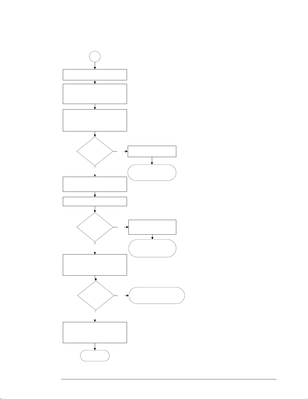
Chapter 5: Troubleshooting
Display Trouble Isolation
Display Trouble Isoltion Flowchart (continued)
ND
Remove acquisition board.
Remove the probe interface
board cable from the power
board.
Check the power board using
the 'Power Boar d Verification'
flowchart in this chapter.
Is
power board
Replace power board.
No
OK?
Yes
Reinstall acquisition board.
Turn on unit.
Does
unit turn on
No
?
Yes
Plug probe interface board
cable back into power board.
Turn unit on.
Does
unit turn on
No
?
Go to 'Primary
Trouble Isolation'.
Replac e acquisition
board.
Go to 'Primar y
Trouble Isolation'
Go to 'AutoPr o b e
Board Trouble Isolation'
Yes
No trouble found.
Loose connec t o rs were
probably reseated.
End
5–20
Page 95

Front Panel Display Trouble Isolation
Front Panel Display Trouble Isolation
Turn unit on. Connect external monitor to VGA port.
Chapter 5: Troubleshooting
Front Panel D isplay Trouble Isolation
Yes
Yes
Replace
SVGA card
Check ffc display
cable connection to
SVGA card and LC D
Does
front panel
display
work?
No
Try a golden SVGA
card to verify failure
Does
display work
with golden
card?
No
Replace
LCD.
display appear
on moni t or
No
front Panel
Check inverter b oard
control cable.
Check voltage on
Cap C2 of SVGA
card. Shou ld be 12V.
Is cable
and voltage
Replace L C D .
front panel
Does
?
Yes
Is
black?
Yes
OK?
Yes
Does
display
work?
Yes
No
No
Replace
inverter.
Connect external
monitor to secondary
displ ay po r t .
Does
display appear
on monitor
?
Yes
No
Try a golden SVGA
card to verify failure
Does
display work
with golden
card?
Yes
Replace
SVGA card.
No
No
Replace
motherboard.
Go to 'Primary Trouble Isolation'.
5–21
Page 96

Chapter 5: Troubleshooting
Front Panel Display Trouble Isolation
WARNING SHOCK HAZARD!
The backlight inverter assembly, which is mounted at the front corner of the oscilloscope near
the flat-panel display, operates at 1.3 kV at turn on. DO NOT handle this assembly while it is in
operation.
WARNING INJURY CAN RESULT!
Once the cover is removed, the fan blades are exposed both inside and outside the chassis.
Disconnect the power cable before working around the fan. Use extreme caution in working with
the oscilloscope when the cover is removed. Install the fan safety shield (Agilent Technologies
P/N 54810-00601) on the side of the chassis over the fan. Failure to observe these precautions
may result in injury.
For information on how to replace the display parts, see chapter 6.
5–22
Page 97

Front Panel Trouble Isolation
Front Panel Trou ble Isolation
Follow the keyboard
troubleshooting guide for
just the powe r button.
Go to ' Primary T rouble
Isolation'.
Chapter 5: Troubleshooting
Front Panel Trouble Isolation
5–23
Page 98

Figure 5-8
Chapter 5: Troubleshooting
Motherboard Verification
Motherboard Verification
The mother board verification requires the use of either a 300 Watt or greater ATX PC power
supply or a test fixture that can be built as follows.
Using an AMP connector, Tyco Electronics part number 2-103168-3 or Agilent part number
1252-1468, solder wires between the pins as shown in Figure 5-8.
Test Fixture
5–24
Page 99

Plug motherboard
connector of ATX
supply into
motherboard power
connector.
Motherboard Verification
Obtain a 300 Watt or greater ATX PC power
supply, or build a test fi xture per instructions
Disconnect ac power.
Using
Yes
ATX power
No
supply?
Chapter 5: Troubleshooting
Motherboard Verification
See Figure 5-8
Plug test fixture onto sense cable
of power harness.
See Fi gu re 5-9
Plug ac power into power
supply being used.
Push power button on front of
instrument.
Do fans
turn on & does
motherboard beep
(@10 sec)?
Yes
Does operating
system boot?
No
Plug motherboard connector of
power harness into motherboard.
Go to
A
Replace m ot h er bo a rdNo
Yes
Motherboard OK.
5–25
Page 100

Figure 5-9
Chapter 5: Troubleshooting
Motherboard Verification
Sense cable
5–26
 Loading...