

Page 1

Infiniium
User’s Quick Start Guide
Agilent Technologies
Page 2

User’s Quick Start Guide
Publication number D8104-97003
January 2006
© Copyright Agilent Technologies 2005-2006
All Rights Reserved
Infiniium Oscilloscopes
Page 3

In This Book
This book gives you the information you need to begin using the Infiniium
Oscilloscopes. It contains four chapters:
Setting up the Oscilloscope Chapter 1 contains inspection, power
requirements, air flow, and setup information.
Working in Comfort Chapter 2 contains recommendations for working
comfortably and safely while operating the Infiniium Oscilloscope.
Using the Oscilloscope Chapter 3 gives an overview of the front panel and
the graphical user interface, and tells you how to perform basic operations with
the oscilloscope.
Using the Built-In Information System Chapter 4 describes the built-in
information system contents and navigation. The built-in information system
contains all of the information that is generally found in a User’s Guide.
• For detailed information on how the oscilloscope makes measurements and
how to use the oscilloscope, see the built-in information system in the
oscilloscope.
• For information on programming the oscilloscope using a computer with a
GPIB interface card or LAN interface card, see the Oscilloscopes
Programmer’s Reference for your model number oscilloscope found in the
Infiniium Information System.
• For information on testing and servicing the oscilloscope, see the Service
Guide manual for your model number oscilloscope found in Infiniium
Information System.
Page 4

Contents
1 Setting Up the Oscilloscope
To inspect package contents 1-3
To inspect options and accessories 1-6
To connect power 1-11
To connect the mouse, the keyboard, a LAN cable, a USB device, a printer,
and a GPIB cable 1-15
To connect oscilloscope probes 1-17
To connect SMA Cables 1-20
To connect the digital probe 1-21
Digital probe lead set 1-22
To tilt the oscilloscope upward for easier viewing 1-26
To turn on the oscilloscope 1-27
To turn off the oscilloscope 1-28
To verify basic operation for the 80000B series oscilloscope 1-29
To verify basic operation for the 8000A series oscilloscope 1-31
Installing application programs on Infiniium 1-33
Changing Windows System Settings 1-34
To clean the oscilloscope 1-35
2 Working in Comfort
About Repetitive Strain Injury 2-3
Mice and Other Input Devices 2-4
3 Using the Oscilloscope
Front Panel 3-4
Acquisition and General Controls 3-5
Horizontal Controls 3-5
Trigger Controls 3-5
Vertical Controls 3-5
Marker and Measurement Controls 3-6
To set the oscilloscope to a known starting condition 3-7
To start and stop waveform acquisition 3-8
To clear the waveform display 3-9
To turn an analog channel on or off 3-10
To turn digital channels on or off 3-11
To change input impedance and input coupling 3-12
To adjust analog channel’s vertical scale and offset 3-13
To adjust digital channel’s vertical size and offset 3-14
To adjust sweep speed and horizontal position 3-15
To magnify a part of the waveform using delayed sweep 3-16
To set the oscilloscope to trigger on an edge 3-17
To use the markers 3-19
To use the quick measurements 3-20
To reinitialize the oscilloscope 3-21
Graphical User Interface 3-23
To perform basic user interface operations 3-30
Contents-1
Page 5

Contents
To select a command from the menu bar 3-33
To select a command from a context-sensitive menu 3-34
To start and stop waveform acquisition 3-37
To clear the waveform display 3-38
To print the screen 3-39
To change waveform brightness 3-40
To turn a channel on or off 3-41
To adjust the vertical offset 3-42
To adjust vertical scaling 3-44
To access the channel setup 3-45
To set the horizontal reference point 3-46
To adjust sweep speed 3-47
To adjust horizontal position 3-48
To access the horizontal setup 3-49
To zoom on a section of the waveform 3-50
To move the markers using the graphical interface 3-52
To make a measurement on a waveform 3-54
To access the trigger setup 3-56
To set an edge trigger 3-57
To set dialog box preferences 3-58
To recover your Infiniium hard disk 3-61
To calibrate the touch screen 3-64
To enable or disable the touch screen 3-65
4 Using the Built-In Information System
To access the information system 4-4
Topic Types 4-7
To navigate through the information system 4-9
To access context-sensitive information 4-10
Contents-2
Page 6

1
Setting Up the Oscilloscope
Page 7

Setting Up the Oscilloscope
This chapter shows you how to set up your Infiniium oscilloscope,
connect power and accessories, and verify general operation.
1-2
Page 8

Setting Up the Oscilloscope
To inspect package contents
To inspect package contents
❏ Inspect the shipping container for damage.
Keep a damaged shipping container or cushioning material until you have
inspected the contents of the shipment for completeness and have checked the
oscilloscope mechanically and electrically.
❏ Verify that you received the following items in the Infiniium Oscilloscope
packaging.
• Infiniium Oscilloscope
•Mouse
• Touchscreen Stylus
• 10073C 10:1 10 MΩ passive probes (one for each analog channel on 8000A
series models only)
• Digital Probe Kit (MSO models only)
• Calibration Cable (80000B series models only)
• SMA to Precision BNC Adaptors (80000B series models only)
• Accessory Pouch
• Front Panel Cover
• Keyboard
•Power cord
• Probe De-skew and Performance Verification Kit (80000B series models
only)
• User’s Quick Start Guide
See the following figures for your model of Infiniium Oscilloscope. (See table
1-4 for the power cord.) If anything is missing, contact your nearest Agilent
Technologies Sales Office. If the shipment was damaged, contact the carrier,
then contact the nearest Agilent Technologies Sales Office.
❏ Inspect the oscilloscope.
• If there is mechanical damage or a defect, or if the oscilloscope does not
operate properly or does not pass performance tests, notify your Agilent
Technologies Sales Office.
• If the shipping container is damaged, or the cushioning materials show signs
of stress, notify the carrier and your Agilent Technologies Sales Office. Keep
the shipping materials for the carrier’s inspection. The Agilent Technologies
Sales Office will arrange for repair or replacement at Agilent’s option without
waiting for claim settlement.
1-3
Page 9

Figure 1-1
Infiniium Oscilloscope
with Accessory Pouch
Setting Up the Oscilloscope
To inspect package contents
Front Panel
Cover
SMA to
Precision
BNC
Adaptors
(2)
Calibration Cable
Mouse
User’s Quick Start Guide
Package Contents for the 80000B Series Infiniium Oscilloscopes
Probe Deskew and
Performance
Verification Kit
Keyboard
Touchscreen Stylus
1-4
Page 10

Figure 1-2
Infiniium Oscilloscope
with Accessory Pouch
Setting Up the Oscilloscope
To inspect package contents
Front Panel
Cover
10073C Probe
Digital Probe
(MSO models
only)
Mouse
SMT IC Clip (MSO models only)
Ground Lead (MSO models only)
Package Contents for the 8000A Series Infiniium Oscilloscopes
Digital Clip Leads
(MSO models only)
Keyboard
User’s Quick Start Guide
Touchscreen Stylus
1-5
Page 11

Setting Up the Oscilloscope
To inspect options and accessories
To inspect options and accessories
❏ Verify that you received the options and accessories you ordered and that
none were damaged.
If anything is missing, contact your nearest Agilent Technologies Sales Office.
If the shipment was damaged, or the cushioning materials show signs of stress,
contact the carrier and your Agilent Technologies Sales Office.
Some accessories that will enhance your work with the 80000B series
oscilloscopes are listed in table 1-1.
Table 1-1
Accessories for the 80000B Series Infiniium Oscilloscopes
Agilent Model
Number
54855-67604 SMA to Precision BNC Adaptor
10833A GPIB cable, 1 m
10833B GPIB cable, 2 m
10833C GPIB cable, 4 m
10833D GPIB cable, 0.5 m
1131A 3.5 GHz InfiniiMax Probe Amplifier
1132A 5 GHz InfiniiMax Probe Amplifier
1134A 7 GHz InfiniiMax Probe Amplifier
1168A 10 GHz InfiniiMax II Probe Amplifier
1169A 12 GHz InfiniiMax II Probe Amplifier
E2668A InfiniiMax Single-ended Connectivity Kit
E2669A InfiniiMax Differential Connectivity Kit
N5381A 12 GHz Solder-in Differential Probe Head
N5382A 12 GHz Differential Browser Probe Head
N5380A SMA Probe Head
1156A 1.5 GHz Single-ended Active Probe
1157A 2.5 GHz Single-ended Active Probe
1158A 4 GHz Single-ended Active Probe
N2774A 50 MHz Current Probe
N2775A Probe Power Supply for N2774A
Description
1-6
Page 12

Setting Up the Oscilloscope
To inspect options and accessories
Agilent Model
Number
E2697A High Impedance Adapter (includes one 10073C passive probe)
54006A 6 GHz probe, 10:1 (500
1184A Testmobile with keyboard and mouse tray and drawer for accessories
E2609B Rackmount Kit
E2655A Additional probe deskew and performance verification kit
E2680A 1 MB Memory upgrade
E2681A EZJIT Jitter Analysis Software
N5400A EZJIT Plus Jitter Analysis Software
E2682A VoiceControl Software
E2699A My Infiniium Integration Software
N5391A Low Speed Serial Data Analysis Software
N5402A CAN Serial Data Analysis Software
E2683A USB 2.0 Test Software
E2625A Communications Mask Test Kit
E2688A High Speed Serial Data Analysis Software
89601A Vector Signal Analysis Software
N5393A PCI Express Electrical Performance Validation and Compliance Software
N5392A Ethernet Electrical Performance Validation and Compliance Software
N5394A DVI Electrical Performance Validation and Compliance Software
N5399A HDMI Electrical Performance Validation and Compliance Software
N5413A DDR2 Clock Characterization Tool
E5850A Time-correlation fixture, integrates oscilloscope and logic analyzer
Description
Ω) or 20:1 (1 kΩ), .25 pf
1-7
Page 13

Setting Up the Oscilloscope
To inspect options and accessories
Some accessories that will enhance your work with the 8000A series
oscilloscopes are listed in table 1-2.
Table 1-2
Accessories for the 8000A Series Infiniium Oscilloscopes
Agilent Model
Number
10070C 20 MHz, 1:1, 1 M
10073C 500 MHz, 10:1, 2.2 M
10076A 4 kV, 250 MHz High Voltage Probe
N2771A 10 kV, 50 MHz High Voltage Probe
10833A GPIB cable, 1 m
10833B GPIB cable, 2 m
10833C GPIB cable, 4 m
10833D GPIB cable, 0.5 m
E2609B Rackmount Kit
1184A Testmobile with keyboard and mouse tray, accessories draw
N2766A PC Board Mini-Probe Socket (horizontal mount, quantity 25)
22768A PC Board Mini-Probe Socket (vertical mount, quantity 25)
10073C 500 MHz, 10:1, 2.2 M
1146A AC/DC Current Probe 100 kHz
1147A AC/DC Current Probe 50 MHz
1130A 1.5 GHz InfiniiMax Probe Amplifier
E2675A InfiniiMax Differential Browser Probe Head
1153A 200 MHz Differential Active Probe
1155A 750 MHz 2-Channel, Low-Mass Single-ended Active Probe
1156A 1.5 GHz Single-ended Active Probe
1159A 1 GHz Differential Probe
1162A 25 MHz, 1:1, 1 M
1163A 1.5 GHz, 10:1, 50
1165A 500 MHz, 10:1, 10 M
1171A 500 MHz, 10:1, 10 M
1250-1454 BNC to Miniature Probe Adapter
10467-68701 4 IC Clips, 0.5 mm
Description
Ω Passive Probe
Ω Passive Probe
Ω Passive Probe
Ω Passive Probe
Ω Passive Probe
Ω Passive Probe
Ω Low-mass Passive Probe
1-8
Page 14

Setting Up the Oscilloscope
To inspect options and accessories
Agilent Model
Number
E2643A Wedge Adapter, 0.5 mm spacing, 16 signals
E2644A Wedge Adapter, 0.65 mm spacing, 16 signals
E2614A Wedge Adapter, 0.5 mm spacing, 8 signals
E2615A Wedge Adapter, 0.65 mm spacing, 3 signals
E2615B 2 Wedge Adapters, 0.65 mm spacing, 3 signals
E2616A Wedge Adapter, 0.65 mm spacing, 8 signals
E2613A Wedge Adapter, 0.5 mm spacing, 3 signals
E2613B 2 Wedge Adapters, 0.5 mm spacing, 3 signals
E2625A Communication Mask Test Kit
E2682A VoiceControl Upgrade Kit
E2699A My Infiniium Integration Software
N5391A Low Speed Serial Data Analysis Software
N5402A CAN Serial Data Analysis Software
E2683A USB 2.0 Test Software
E2625A Communications Mask Test Kit
N5384A High Speed Serial Data Analysis Software
89601A Vector Signal Analysis Software
N5392A Ethernet Electrical Performance Validation and Compliance Software
E5850A Time-correlation fixture, integrates oscilloscope and logic analyzer
N5397A FPGA Dynamic Probe for Infiniium MSO oscilloscopes
E2681A EZJIT Jitter Analysis Software
Description
1-9
Page 15

Setting Up the Oscilloscope
To inspect options and accessories
Acquisition memory upgrades are available to protect your Infiniium
oscilloscope investment when acquisition memory needs change. You can
install memory upgrades without opening the oscilloscope case or requiring onsite service. Acquisition memory upgrades are listed in table 1-3.
Table 1-3
Acquisition memory upgrades for Infiniium Oscilloscopes
Agilent Model
Number
N5404A Infiniium 80000B Series Oscilloscopes
N5407A Infiniium 8000A Series Oscilloscopes
Description
2 MPts (half channel mode)
1 MPts (full channel mode)
64 MPts (half channel mode, 4 GSa/s)
32 MPts (half channel mode, ≤ 2 GSa/s)
Option 040 — 8 MPts (half channel mode), 4 MPts (full channel mode)
Option 080 — 16 MPts (half channel mode), 8 MPts (full channel mode)
Option 160 — 32 MPts (half channel mode), 16 MPts (full channel mode)
Option 320 — 64 MPts (half channel mode), 32 MPts (full channel mode)
Option 640 — 128 MPts (half channel mode), 64 MPts (full channel mode)
1-10
Page 16

Figure 1-3
Setting Up the Oscilloscope
To connect power
To connect power
1 Position the oscilloscope where it will have sufficient clearance for
airflow around the top, back, and sides.
2 Position the oscilloscope so that it is not difficult to unplug the power
cord.
Minimum 0 mm
Minimum 22 mm
Minimum 85 mm
both sides
Airflow requirements 250 cfm
Positioning the Infiniium Oscilloscope with Sufficient Clearance
Minimum 39 mm
1-11
Page 17

Figure 1-4
Setting Up the Oscilloscope
To connect power
3 Connect the power cord to the rear of the oscilloscope, then to a
suitable ac voltage source (100 to 240 VAC ±10%, 47 to 63 Hz all models
for the 8000A series and 100 to 240 VAC ±10%, 47 to 63 Hz for the 80000B
series)
Maximum power dissipation: 80000B series is 550 W and 8000A series is 440 W.
Infiniium Oscilloscope Power Cord Connection
The oscilloscope power supply automatically adjusts for line input voltages in
the range 100 to 240 VAC. Therefore, you do not need to adjust an input line
voltage setting. The line cord provided is matched by Agilent Technologies to
the country of origin of the order.
4 Ensure that you have the correct line cord. See table 1-4.
1-12
Page 18

Setting Up the Oscilloscope
To connect power
Table 1-4
Power Cords
Plug Type Part No. Option No. Country
8120-1703 900 United Kingdom
8120-0696 901 Australia
8120-1692 902 Europe
8120-1521 903 United States
8120-2296 906 Switzerland
8120-2957 912 Denmark
8120-4600 917 Africa
8120-4754 918 Japan
8120-6799 919 Israel
1-13
Page 19

Setting Up the Oscilloscope
To connect power
Plug Type Part No. Option No. Country
8120-6871 920 Argentina
8120-6979 921 Chile
8120-8377 922 China
8120-8871 927 Thailand
1-14
Page 20

Setting Up the Oscilloscope
To connect the mouse, the keyboard, a LAN cable, a USB device, a printer, and a GPIB
cable
To connect the mouse, the keyboard, a LAN cable, a USB
device, a printer, and a GPIB cable
See Figure 1-5 for the location of the connectors.
Mouse Plug the mouse into the matching connector on the back panel of the
oscilloscope. The connectors are labeled 1 and 5.
While you can operate many oscilloscope functions using only the front-panel keys and
knobs, you will need the mouse to access advanced oscilloscope functions through the
graphical interface, or to find out more about the oscilloscope through the built-in
information system.
Keyboard Plug the keyboard cable into the connector labeled 2 on the back panel of the
oscilloscope.
A keyboard cannot be plugged into the oscilloscope after the Windows operating system
has started booting.
LAN Cable Connect your LAN cable to the RJ-45 connector labeled 3 on the back panel of
the oscilloscope.
After you have connected to the LAN card, you must set up the network. Before you try
to setup your network, you should exit the oscilloscope application. If you do not know
how to setup a network in Windows XP, see your network administrator or use the
Windows XP on-line help.
USB
Connectors Connectors can be used for any USB devices. There is also a USB connector in
the upper right-hand corner of the front panel.
Printer Cable If you have a parallel (Centronics) printer, you will need a parallel printer cable.
Connect cable into the connector labeled 4.
If you have a serial printer, you will need a 9-pin to 25-pin serial printer cable.
Some printers may require other cable configurations, but the oscilloscope has
a 9-pin serial connector. Connect cable into the connector labeled 7.
GPIB Cable Attach the GPIB connector to the GPIB interface card connector labeled 6 on
the rear of the oscilloscope.
1-15
Page 21

Figure 1-5
Setting Up the Oscilloscope
To connect the mouse, the keyboard, a LAN cable, a USB device, a printer, and a GPIB
cable
Back Panel
3
1
2
7
4
5
5
6
1-16
Page 22

Figure 1-6
Setting Up the Oscilloscope
To connect oscilloscope probes
To connect oscilloscope probes
There are optional Infiniium oscilloscope probes, such as the 1130 and 1160
series probes, that connect to the oscilloscope differently than other
oscilloscope probes. Use the following steps to connect these snap-on probes
to the oscilloscope.
1 Attach the probe connector to the desired oscilloscope channel or
trigger input. Push it straight on until it latches into place.
Attaching the Probe Connector
1-17
Page 23

Figure 1-7
Probing the Circuit
Setting Up the Oscilloscope
To connect oscilloscope probes
2 Connect the probe to the circuit of interest using the browser or other
probing accessories.
3 To disconnect the probe, push the small latch on top of the probe
connector to the left, then pull the connector body away from the front
panel of the oscilloscope without twisting it.
1-18
Page 24

Figure 1-8
Disconnecting the Oscilloscope Probe
Setting Up the Oscilloscope
To connect oscilloscope probes
CAUTION Do not attempt to twist the snap-on probes on or off the oscilloscope’s BNC
connector. Twisting the probe connector body will damage it.
CAUTION For the 8000A series oscilloscopes do not exceed the maximum input voltage
CAUTION For the 80000B series oscilloscopes do not exceed the maximum input voltage
!
rating. The maximum input voltage for 50 Ω inputs is 5 Vrms, CAT I. Maximum
voltage at 1 MΩ impedance is ±100 V (dc + ac) [ac < 10 kHz], CAT I.
!
rating. The maximum input voltage for the 50 Ω inputs is ±5 Vpeak, CAT I.
1-19
Page 25

Figure 1-9
Setting Up the Oscilloscope
To connect SMA Cables
To connect SMA Cables
You can connect an SMA cable to the 80000B series Infiniium oscilloscopes by
using the 54855-67604 SMA to precision BNC adaptor.
1 Attach the two SMA to precision BNC adaptors to the ends of an SMA
cable.
2 Push the SMA to precision BNC adaptors onto the oscilloscope BNC
connectors.
3 Tighten the thumbscrews until they are snug.
Thumb screw
SMA cable
Connecting SMA to Precision BNC Adaptors
SMA to precision
BNC adaptor
1-20
Page 26

Figure 1-10
Setting Up the Oscilloscope
To connect the digital probe
To connect the digital probe
The MSO (Mixed Signal) series oscilloscopes are the only oscilloscopes that have
tightly integrated 16 digital timing channels.
The digital flying lead marked clk (clock) is unused. All the other digital flying leads
are used for the digital timing channels.
1 Push the small connector end of the digital cable with the tab key facing
left into the digital connector.
2 Tighten both thumb screws.
Connecting the Digital Cable to the Oscilloscope
1-21
Page 27

Figure 1-11
Setting Up the Oscilloscope
Digital probe lead set
Digital probe lead set
The MSO (Mixed Signal) oscilloscopes have tightly integrated16 digital timing
channels.
The digital flying lead marked clk (clock) is unused. All the other digital flying leads
are used for the digital timing channels.
The flying lead set has 16 digital channels with a ground lead for each channel.
Digital Flying Lead Set
If a 0.63 mm square pin or a 0.66 diameter round pin is installed on the circuit
under test, the signal and ground leads can be directly connect to these pins.
Otherwise, the IC clips can be used to connect to the circuit.
CAUTION Do not exceed the maximum input voltage rating of ±40 V peak, CAT I.
!
Probe tip isolation network and equivalent load
The probe tips of the probe lead set contain an isolation network which serves
to minimize the loading effect of the digital channels on the circuit under test.
The isolation network schematic is shown in Figure 1-12.
1-22
Page 28

Figure 1-12
Figure 1-13
Setting Up the Oscilloscope
Digital probe lead set
Ω
90.9 k
To Oscilloscope
Signal
250
Ω
8.2 pF
Probe Tip Isolation Network
The loading effect of the probe tip on the circuit under test is represented by
the circuit shown in the equivalent load schematic in Figure 1-13.
370
Ω
Signal
Equivalent Load including oscilloscope
100 k
7.4 pF1.5 pF
Ω
1-23
Page 29

Figure 1-14
Setting Up the Oscilloscope
Digital probe lead set
Direct connection through 40-pin connector
The probe cable can also be directly plugged into various 40-pin connectors on
the circuit board under test. This requires each signal pin of the 40-pin
connector to have an isolation network (Figure 1-12) on the circuit board. The
pinout of the 40-pin connector is shown in Figure 1-14.
+5 V (see note)
Do not connect
+5 V (see note)
40-pin Connector Pinout
Unused
D15
D14
D13
D12
D11
D10
D9
D8
D7
D6
D5
D4
D3
D2
D1
D0
1
3
5
7
9
11
13
15
17
19
21
23
25
27
29
31
33
35
37
39
2
4
6
8
10
12
14
16
18
20
22
24
26
28
30
32
34
36
38
40
Power Gnd
Signal Gnd
Signal Gnd
Signal Gnd
Signal Gnd
Signal Gnd
Signal Gnd
Signal Gnd
Signal Gnd
Signal Gnd
Signal Gnd
Signal Gnd
Signal Gnd
Signal Gnd
Signal Gnd
Signal Gnd
Signal Gnd
Signal Gnd
Signal Gnd
Power Gnd
Note: +5 V is supplied by the oscilloscope to provide power for the demo board. DO
NOT connect these pins to the circuit board under test.
CAUTION Do not exceed the maximum input voltage rating of ±40 V peak, CAT I. The
!
isolation network must be used on all digital channels for this to be valid.
1-24
Page 30

Setting Up the Oscilloscope
Digital probe lead set
For more information on digital probing solutions, search for the document
titled “Probing Solutions for Logic Analysis Systems” (Agilent part number
5968-4632E) on the Agilent Technologies web site at www.agilent.com.
The MSO probe cable is fully compatible with various 40-pin connector probes,
such as Mictor and Soft Touch.
1-25
Page 31

Figure 1-15
Setting Up the Oscilloscope
To tilt the oscilloscope upward for easier viewing
To tilt the oscilloscope upward for easier viewing
1 Lift up the front of the oscilloscope, grasp the wire bail near the center,
and pull it down and forward until it latches into place.
Latching the Oscilloscope Front Feet
1-26
Page 32

Figure 1-16
Setting Up the Oscilloscope
To turn on the oscilloscope
To turn on the oscilloscope
The first time that you turn on the oscilloscope, you will need to have a mouse
connected. The mouse is needed to accept the Microsoft end-user license
agreement for Windows XP Pro.
1 Depress the power switch in the lower left-hand corner of the
oscilloscope front panel.
Turning on the Oscilloscope
After a short initialization period, the oscilloscope display appears. The
oscilloscope is ready to use.
2 You can connect and disconnect probes and BNC cables while the
oscilloscope is turned on.
1-27
Page 33

Setting Up the Oscilloscope
To turn off the oscilloscope
To turn off the oscilloscope
1 Momentarily depress the power switch at the lower left-hand corner of
the oscilloscope front panel. The oscilloscope will go through a normal
Windows shutdown process.
1-28
Page 34

Figure 1-17
Setting Up the Oscilloscope
To verify basic operation for the 80000B series oscilloscope
To verify basic operation for the 80000B series
oscilloscope
1 Connect one end of the calibration cable using SMA to precision BNC
adaptors to channel 1.
2 Connect the other end of the calibration cable using the SMA to
precision BNC adaptor to the Aux Out connecter on the front panel.
Calibration
Output
Verifying Basic Oscilloscope Operation for 80000B Series Oscilloscopes.
3 Press the Default Setup key on the front panel.
The display will pause momentarily while the oscilloscope is configured to its
default settings.
4 Press the Autoscale key on the front panel.
The display will pause momentarily while the oscilloscope adjusts the sweep
speed and vertical scale. You should then see a square wave with peak-to-peak
amplitude of approximately 5 divisions and a shows about four cycles on screen.
If you do not see the waveform, ensure your power source is adequate, the
oscilloscope is properly powered-on, and the probe is connected securely to the
front-panel channel input BNC and to the probe calibration output.
5 Move the mouse around the mouse surface and verify that the on screen
pointer follows moves with the mouse movement.
1-29
Page 35

Setting Up the Oscilloscope
To verify basic operation for the 80000B series oscilloscope
6 Touch the pointer of the touch screen sylus to the surface of the screen
and move it around while verifying that the pointer follows the
movement.
1-30
Page 36

Figure 1-18
Setting Up the Oscilloscope
To verify basic operation for the 8000A series oscilloscope
To verify basic operation for the 8000A series
oscilloscope
1 Connect a passive probe to channel 1.
2 Attach the passive probe to the calibration output on the front panel of
the oscilloscope.
Use a probe grabber tip so you do not need to hold the probe. The calibration
output is marked with a square wave symbol.
Calibration
Output
Verifying Basic Oscilloscope Operation for 8000A Series Oscilloscopes.
3 Press the Default Setup key on the front panel.
The display will pause momentarily while the oscilloscope is configured to its
default settings.
4 Press the Autoscale key on the front panel.
The display will pause momentarily while the oscilloscope adjusts the sweep
speed and vertical scale. You should then see a square wave with peak-to-peak
amplitude of approximately 5 divisions and a shows about four cycles on screen.
If you do not see the waveform, ensure your power source is adequate, the
oscilloscope is properly powered-on, and the probe is connected securely to the
front-panel channel input BNC and to the probe calibration output.
1-31
Page 37

Setting Up the Oscilloscope
To verify basic operation for the 8000A series oscilloscope
5 Move the mouse around the mouse surface and verify that the on screen
pointer follows moves with the mouse movement.
6 Touch the pointer of the touch screen stylus to the surface of the screen
and move it around while verifying that the pointer follows the
movement.
1-32
Page 38

Setting Up the Oscilloscope
Installing application programs on Infiniium
Installing application programs on Infiniium
Infiniium is an open Windows system. This allows you to install your own
application software. Agilent has verified that the following applications are
compatible with the Infiniium oscilloscope application.
• Agilent Vector Signal Analysis
• Agilent VEE Pro
• Amherst Systems Oscilloscope Tools
• Microsoft Office 2000
• MathWorks MATLAB
• Mathsoft MathCad 2001i
• McAfee VirusScan
• Symantec Norton AntiVirus
Before installing any software, you should exit the oscilloscope application.
If you install an application other than those which Agilent has tested, it is
possible that it could break the oscilloscope application. This would potentially
require you to recover the oscilloscope hard drive using the hard drive’s hidden
recovery partition.
1-33
Page 39

Setting Up the Oscilloscope
Changing Windows System Settings
Changing Windows System Settings
Before changing any Windows System settings outside of the oscilloscope
application you should Exit the oscilloscope application.
There are several Windows System settings that can be changed to suit your
own personal preferences. However, there are some system settings that you
should avoid changing because it will interfere with the proper operation of the
oscilloscope.
• Do not change the Power Options.
• Do not change the System Properties Hardware Tab settings.
• Do not change the Regional and Language Options Advanced Tab
settings.
• Do not remove Fonts.
• Display Settings
• Do not change the screen resolution from 1024 by 768 pixels or the color
quality from Highest (32 bit).
• Do not change the Font size to Extra Large.
• Do not use a Menu font size greater than 14 points.
• Do not use the Administrative Tools to enable or disable Internet
Information Services (Web Server). Use the Infiniium Web Control
dialog box to enable or disable the Web Server.
• Do not delete or modify the InfiniiumAdmin user account.
1-34
Page 40

Setting Up the Oscilloscope
To clean the oscilloscope
To clean the oscilloscope
• Clean the oscilloscope with a soft cloth dampened with a mild soap and
water solution.
CAUTION Do not use too much liquid in cleaning the oscilloscope. Water can enter the
Infiniium front panel, damaging sensitive electronic components.
1-35
Page 41

1-36
Page 42

2
Working in Comfort
Page 43

Introduction
To optimize your comfort and productivity, it is important that you set
up your work area correctly and use your Infiniium oscilloscope properly.
With that in mind, we have developed some set-up and use
recommendations for you to follow based on established ergonomic
principles.
Improper and prolonged use of keyboards and input devices are among
those tasks that have been associated with repetitive strain injury (RSI)
to soft tissues in the hands and arms. If you experience discomfort or
pain while using the oscilloscope, discontinue use immediately and
consult your physician as soon as possible. For more information on RSI
you may wish to consult the About Repetitive Strain Injury section.
Please study the recommendations offered here in this chapter.
Included there are references to relevant parts of international
standards, regulations and guidelines, such as ISO 9241 and the
European Community Display Screen Equipment directive. You may
also wish to consult your employer’s human resources department or
other relevant departments for guidance specific to your company.
2-2
Page 44

Working in Comfort
About Repetitive Strain Injury
About Repetitive Strain Injury
Because your comfort and safety are our primary concern, we strongly
recommend that you use the Infiniium oscilloscope in accordance with
established ergonomic principles and recommendations. Scientific literature
suggests that there may be a relationship between injury to soft tissues—
especially in the hands and arms—and prolonged improper use of keyboards or
other equipment requiring repeated motions of the hands and forearms. This
literature also suggests that there are many other risk factors that may increase
the chance of such injury, commonly called Repetitive Strain Injury.
What is RSI? Repetitive Strain Injury (RSI—also known as cumulative trauma disorder or
repetitive motion injury) is a type of injury where soft tissues in the body, such
as muscles, nerves, or tendons, become irritated or inflamed. RSI has been a
reported problem for those who perform repetitive tasks such as assembly line
work, meatpacking, sewing, playing musical instruments, and computer work.
RSI also has been observed in those who frequently engage in activities such as
carpentry, knitting, housework, gardening, tennis, windsurfing and lifting
children.
What causes RSI? The specific causes of RSI have not been established. Nevertheless, the
incidence of RSI has been associated with a variety of risk factors, including:
• Too many uninterrupted repetitions of an activity or motion.
• Performing an activity in an awkward or unnatural posture.
• Maintaining static posture for prolonged periods.
• Failing to take frequent short breaks.
• Other environmental and psychosocial factors.
In addition, there have been reports associating the occurrence of RSI with the
use of keyboards, mice, and other input devices. Also, certain medical
conditions, such as rheumatoid arthritis, obesity and diabetes, may predispose
some people to this type of injury.
What if I experience
discomfort? If you are experiencing any discomfort, seek professional medical advice
immediately. Typically, the earlier a problem is diagnosed and treated, the
easier it is to resolve.
2-3
Page 45

Working in Comfort
Mice and Other Input Devices
Mice and Other Input Devices
Various aspects of using mice and other input devices may increase your risk of
discomfort or injury. Observing the following recommendations may reduce
that risk.
• Try to keep your hand, wrist, and forearm in a neutral position while using
your mouse or other input device.
• If you use your thumb to rotate the ball on a trackball or spaceball, keep it
in a relaxed, natural shape, and maintain a neutral posture in your hand,
wrist, and forearm.
• Hold the mouse gently by draping your fingers over it. Keep your hand
relaxed and fingers loose. Do not grip the mouse tightly.
• It takes very little pressure or force from your fingers to activate the buttons
or scroll wheel on your mouse, scrolling mouse, trackball, or other input
device. Using too much force can place unnecessary stress on the tendons
and muscles in your hands, wrists, and forearms.
• If you are using a scrolling mouse, be sure to keep your fingers and hand in
a relaxed, neutral position when activating the scroll wheel. Also, this type
of mouse features software that can minimize the number of mouse
movements or button clicks.
• When using a mouse, trackball, or other input device, position it as close to
the keyboard as possible, and keep it at the same level as you do not have to
stretch while using it.
• Be sure to keep your mouse and trackball clean. Regular removal of
accumulated dust and dirt helps ensure proper tracking and reduces
unnecessary hand and wrist motions.
2-4
Page 46

3
Using the Oscilloscope
Page 47

Using the Oscilloscope
The Infiniium Oscilloscope is designed to be easy to use.
• The familiar front-panel oscilloscope interface with knobs and keys is
optimized for the most common kinds of troubleshooting tasks and
basic measurements. See “Using the Front Panel” on page 3-3.
• The graphical interface with menus, windows, dialogs, and toolbars
provides easy logical access to dozens of configuration and analysis
tools, making it easy for you to set up and make the most complex
measurements. The interface also allows you to use the Infiniium
oscilloscope’s built-in information system, which gives detailed
information on using the oscilloscope to make measurements. See
“Using the Graphical Interface” on page 3-22.
3-2
Page 48

Using the Oscilloscope
Using the Front Panel
The Infiniium Oscilloscope front panel has been designed to give you
direct access to the functions needed to perform the most common
measurements needed in troubleshooting, using a traditional
oscilloscope interface. Knobs and keys are included to enable direct
setting of vertical and horizontal parameters. In addition, the front panel
has a set of LED (Light-Emitting Diode) indicators; by using these and
the display, you can assess the configuration of the oscilloscope at a
glance—there is no need to enter a series of keystrokes to navigate
through complex menus.
The Infiniium Oscilloscope uses color consistently throughout the front
panel and user interface. For example, the color of the knob for channel
1 is the same color as the waveform for channel 1. All the configuration
items and values related to channel 1 are displayed in the same color.
3-3
Page 49

Figure 3-1
Using the Oscilloscope
Front Panel
Front Panel
Figure 3-1 shows a typical Infiniium oscilloscope front panel.
Horizontal
controls
Acquisition and
general controls
Trigger
controls
Power Switch
Infiniium Oscilloscope Front Panel
Using the front panel, you can configure the Infiniium oscilloscope for most
troubleshooting tasks. The control categories are:
• Acquisition and general controls
• Horizontal controls
• Trigger controls
• Vertical controls
• Marker and measurement controls
3-4
Marker and
Measurement Controls Vertical controls
Page 50

Using the Oscilloscope
Acquisition and General Controls
Acquisition and General Controls
Using the acquisition and general controls, you control whether the oscilloscope
is running or stopped. Other keys allow you to reset the oscilloscope to its
default setup, automatically configure the oscilloscope for the current input
signals (Autoscale), or clear the waveforms from the display and reset such
things as measurement statistics and averaging.
Horizontal Controls
Using the horizontal controls, you configure the oscilloscope’s sweep speed
(seconds per division) and horizontal position of the waveform. You can also
view a magnified section of the waveform using the delayed sweep window,
which uses software to expand part of the acquisition memory.
Trigger Controls
Using the trigger controls, you set the conditions on which the oscilloscope will
trigger and acquire an input signal. You can set up a variety of trigger conditions.
Edge and glitch triggers can be selected from the front panel, and the
parameters for edge triggering can be set up here as well. Some glitch trigger
parameters (such as glitch width) and all advanced trigger configurations are
set up using the graphical interface.
Trigger configuration settings you make using the graphical interface are
reflected in the front-panel status indicators, and will remain set unless you
change them (either using the front panel or the graphical interface) or press
the Default Setup key. See “Using the Graphical Interface” on page 3-22 for
information on accessing the graphical interface.
Vertical Controls
Using the vertical controls, you set the vertical scaling (volts per division) and
vertical offset. You can also turn the display on or off for a particular channel.
3-5
Page 51

Using the Oscilloscope
Marker and Measurement Controls
Marker and Measurement Controls
Using the marker and measurement controls, you control two sets of markers
within the oscilloscope graticule. You use markers to make more accurate
measurements of waveform events than you could make visually. Both time
and voltage differences between the markers are updated continuously on the
screen. By default, the markers track the source waveform. Voltage
measurements from the markers are the value of the waveform at the time set
with the marker arrow keys.
The QuickMeas key initiates five preset measurements on the waveforms. Both
quick measurements and markers will function on any input waveform; simply
continue to press and release one of the keys (either QuickMeas, Marker A, or
Marker B) to cycle through all the waveforms on the screen, then to the off
state. You choose which five measurements will be performed by using the
measurement configuration commands in the graphical interface.
3-6
Page 52

Using the Oscilloscope
To set the oscilloscope to a known starting condition
To set the oscilloscope to a known starting condition
• Press the Default Setup key.
You can set up the oscilloscope for many different kinds of complex
measurements. To easily reset the oscilloscope to a known measurement
configuration, use the Default Setup key.
If you use the Default Setup key, you can select Undo Default Setup from the
Control menu to return the oscilloscope to its original configuration.
Save the Current Oscilloscope Configuration
Before using Default Setup, you may want to save the current oscilloscope
configuration for later use. See the built-in information system (described in
chapter 4) for instructions on saving and recalling setups, and for information on the
exact configuration that is set when you press Default Setup.
3-7
Page 53

Figure 3-2
Using the Oscilloscope
To start and stop waveform acquisition
To start and stop waveform acquisition
• To start waveform acquisition, press the Run key.
The oscilloscope begins acquiring data. When it receives a trigger signal, it
finishes acquiring data, updates the display, then starts another acquisition
cycle if it is in triggered or auto trigger mode. If it is in single sweep mode, it
stops after updating the display.
• To stop waveform acquisition, press the Stop key.
The oscilloscope stops acquiring data. Whatever data was last acquired remains
on the screen.
Start
waveform
acquisition
Stop
waveform
acquisition
Run and Stop Keys
3-8
Page 54

Figure 3-3
Using the Oscilloscope
To clear the waveform display
To clear the waveform display
• Press the Clear Display key.
The oscilloscope clears the waveform display. If the oscilloscope is in Run mode
and is receiving triggers, it will update the display as it collects new waveform
data. Clearing the waveform display also resets averaging, infinite persistence,
and color grade persistence, histogram, mask testing database, and
measurement statistics.
Erases the current
waveform display
Clear Display Key
3-9
Page 55

Figure 3-4
Using the Oscilloscope
To turn an analog channel on or off
To turn an analog channel on or off
• To turn an analog channel on, press the channel number key until it is
illuminated. To turn it off, press the channel number key again.
If you are not using a particular channel, you can turn it off. This simplifies the
waveform display and also increases the display update rate. While a channel
is turned off, data acquisition continues for that analog channel. Thus, you can
still use the analog channel as a source for functions.
Using an Analog Channel as External Trigger
Any analog channel can be used as a trigger source. If you need an external trigger
but do not need all analog channels, you can use an analog channel as an external
trigger without displaying it by turning the analog channel display off.
Use this key to turn
analog channel 1 on or
off
Channel Key
3-10
Page 56

Figure 3-5
Using the Oscilloscope
To turn digital channels on or off
To turn digital channels on or off
Digital channels are only available on the MSO series oscilloscopes.
• To turn digital channels on, press the digital channel number key until
it is illuminated. To turn them off, press the digital channel number
key again.
The only digital channels that are displayed are the ones that are turned on in the
Digital Setup dialog box.
Use this key to turn digital
channels on or off
Digital Channels Key
3-11
Page 57

Using the Oscilloscope
t
To change input impedance and input coupling
To change input impedance and input coupling
Input impedance and input coupling are only available on the 8000A series
oscilloscopes.
• To change the input impedance, press the Input key until the LED for
the desired impedance is illuminated.
Choices are 50 Ω and 1 MΩ.
An identified active or passive probe automatically sets the proper input impedance.
• To change the input coupling, press the Coupling key until the LED for
the desired coupling is illuminated.
Choices are AC and DC. If you change the input coupling to AC when 50 Ω
impedance is selected, the input impedance changes to 1 MΩ. If you change
the input impedance to 50 Ω, the input coupling changes to DC.
Figure 3-6
Use this key to change
he input coupling
Input Impedance and Coupling
Use this key to set input
impedance
3-12
Page 58

Figure 3-7
Using the Oscilloscope
To adjust analog channel’s vertical scale and offset
To adjust analog channel’s vertical scale and offset
• To make the waveform bigger, turn the vertical scale knob clockwise.
To make it smaller, turn the knob counter-clockwise.
The vertical scale knob is the larger of the two knobs for a channel. It is marked
with a set of sine wave symbols. Decreasing the vertical scale makes the
waveform bigger. There are fewer volts displayed per division. Increasing the
vertical scale makes the waveform smaller. There are more volts displayed per
division.
• To move the waveform toward the top of the display, turn the vertical
offset knob clockwise. To move it toward the bottom of the display,
turn the knob counter-clockwise.
The vertical offset knob is the smaller of the two knobs for a channel. It is
marked with a set of arrows.
Vertical scale knob—
use this to adjust
vertical scaling
(in volts per division)
Vertical offset knob—
use this to adjust
vertical offset (position)
Vertical Scale and Offset Controls
3-13
Page 59
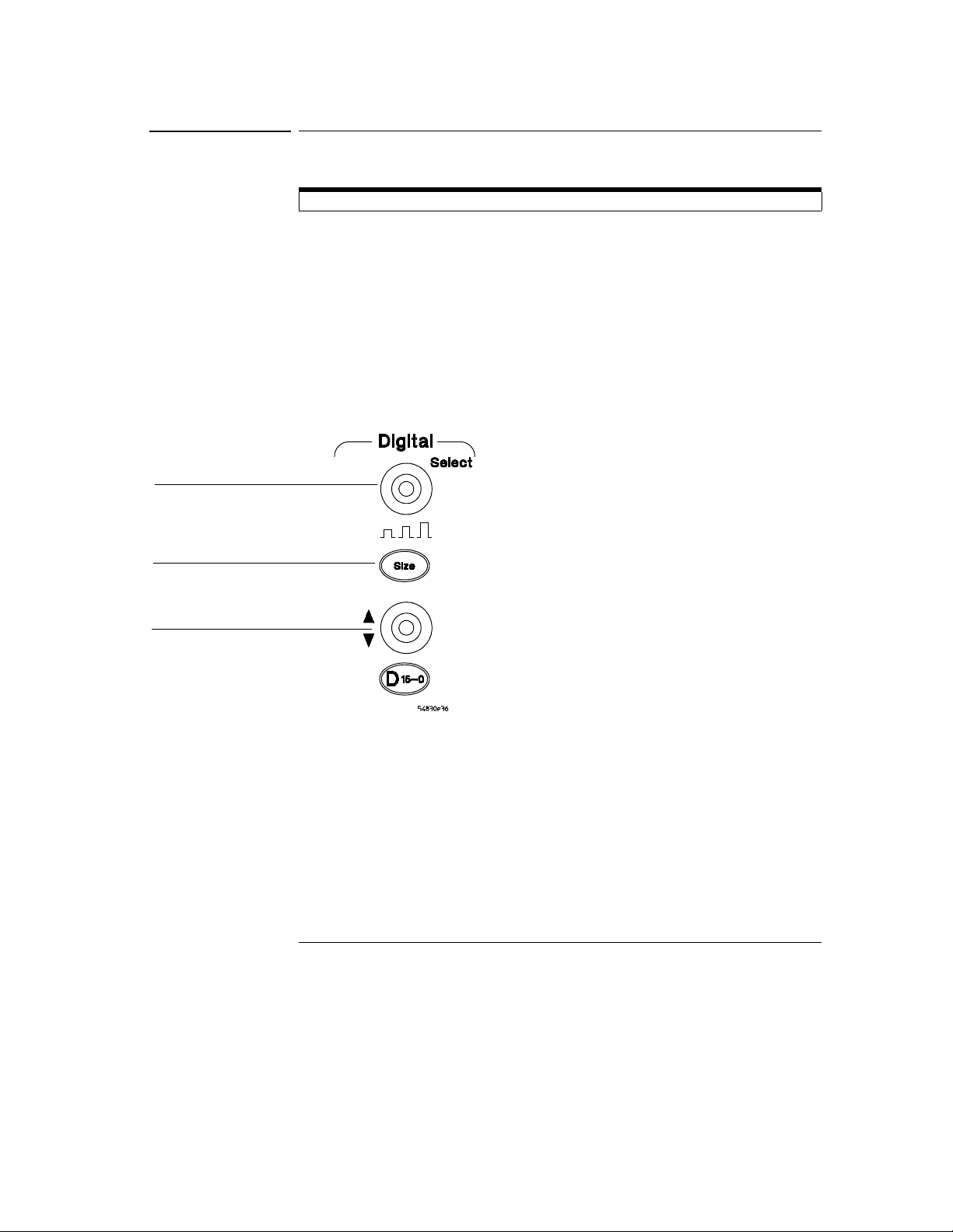
Figure 3-8
Using the Oscilloscope
To adjust digital channel’s vertical size and offset
To adjust digital channel’s vertical size and offset
Digital channels are only available on the MSO series oscilloscopes.
• To select the digital channel which is affected by the vertical offset
knob, turn the select knob clockwise to move toward the top-most
digital channel. Turn the knob counter-clockwise to move toward the
bottom most digital channel.
• To make the waveform bigger or smaller, press the size button.
• To move the waveform toward the top of the display, turn the vertical
offset knob clockwise. To move it toward the bottom of the display,
turn the knob counter-clockwise.
Select knob— use this to
choose the digital channel
affected by the vertical offset
knob vertical size
Size button— use this to adjust
vertical size
Vertical offset knob—use this
to adjust vertical offset
(position)
Digital Channel’s Vertical Size and Offset Controls
3-14
Page 60

Using the Oscilloscope
To adjust sweep speed and horizontal position
To adjust sweep speed and horizontal position
• To stretch the waveform horizontally, turn the sweep speed knob
clockwise. To shrink it horizontally, turn the knob counter-clockwise.
The sweep speed knob is the larger of the two horizontal control knobs. It is
marked with a set of sine wave symbols. Stretching the waveform means there
are fewer seconds displayed per division. Shrinking the waveform means there
are more seconds displayed per division.
• To move the waveform to the right, turn the horizontal position knob
clockwise. To move the waveform to the left, turn the horizontal
position knob counter-clockwise.
Moving the waveform to the right shows more of the pretrigger data (data
acquired before the trigger event). Moving the waveform to the left shows more
of the post-trigger data (data acquired after the trigger event).
The horizontal position knob is the smaller of the two horizontal control knobs.
It is marked with a set of arrows. There is a detent programmed into the
software so there is a momentary pause at zero while you are turning the knob.
Continuing to turn the knob will move the horizontal position through zero.
Figure 3-9
Sweep speed
knob—use this to
adjust the sweep
speed
Horizontal position
knob—use this to
adjust the
horizontal position
Horizontal Sweep Speed and Position Controls
3-15
Page 61

Figure 3-10
Using the Oscilloscope
To magnify a part of the waveform using delayed sweep
To magnify a part of the waveform using delayed sweep
• To turn on the delayed sweep, press Delayed. To turn it off, press
Delayed again.
The waveform display area splits into two regions. The top one is the main
sweep. The bottom is the delayed sweep, which represents a software
expansion of the acquired waveform data. A section of the waveform in the
main sweep window is highlighted to indicate the part shown in the delayed
sweep window.
The horizontal sweep speed and horizontal position controls now change how
the waveform is shown in the delayed sweep window. The sweep speed will
change the amount of magnification, while the position will change the part of
the waveform in the main sweep window that is shown in the delayed sweep
window.
Press this key to magnify
a part of the waveform in
a new window on the
display
Magnifying Part of the Waveform with Delayed Sweep
3-16
Page 62

Figure 3-11
Using the Oscilloscope
To set the oscilloscope to trigger on an edge
To set the oscilloscope to trigger on an edge
1 Press and release the Mode key until the Edge LED indicator is
illuminated.
2 Press and release the Source key until the desired source LED is
illuminated.
You can choose any of the channels or the Aux Trig In as the source for an edge
trigger.
3 Press the Slope key until the desired slope LED is illuminated.
You can have an edge trigger on a rising or falling edge.
4 Press the Sweep key until the Trig’d LED is illuminated.
The oscilloscope will wait for the edge before initiating a sweep.
5 Turn the Level knob to adjust the voltage level at which the oscilloscope
will trigger.
Set trigger level
Select Edge
mode
Select the
trigger
source
Trigger Controls and Indicators for 80000B Series Oscilloscopes
Select rising
or falling
edge for the
trigger
Select Trig’d
Single, or Auto
Set the sensitivity
characteristics for the
trigger (80000B series
oscilloscopes)
3-17
Page 63
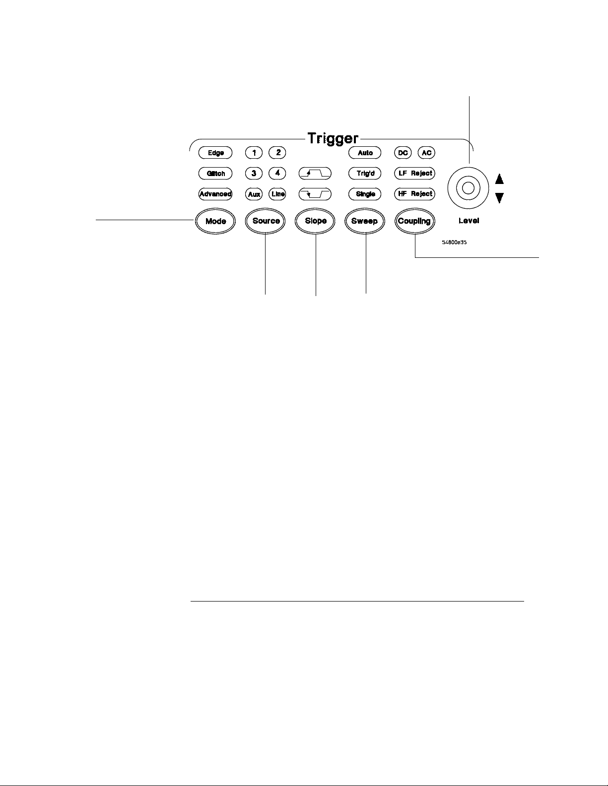
Figure 3-12
Select Edge
mode
Using the Oscilloscope
To set the oscilloscope to trigger on an edge
Set trigger level
Select the
trigger
source
Trigger Controls and Indicators for 8000A Series Oscilloscopes
Select rising
or falling
edge for the
trigger
Select Trig’d
Single, or Auto
Set the coupling
characteristics for the
trigger (8000A series
oscilloscopes)
3-18
Page 64

Using the Oscilloscope
To use the markers
To use the markers
Markers make it easier to make precise measurements because the marker
measurement readouts show exact voltage and time positions for the markers.
The measurements are based on actual waveform data from the acquisition
system, not on approximations based on the display position, so you can be sure
that the values are highly accurate.
• To turn on Marker A, press the Marker A key.
Marker A has a solid line pattern on the waveform display. It is associated with
the first available source on the display. Press the key again to move to the next
available source. When there are no more sources, the marker turns off.
• To turn on Marker B, press the Marker B key.
Marker B has a dashed line pattern on the waveform display. It is associated
with the first available source on the display. Press the key again to move to
the next available source. When there are no more sources, the marker turns off.
• To move a marker on the waveform, press and hold the left arrow or
right arrow key next to the desired Marker key. Release the key when
the marker is at the desired waveform event.
The marker snaps to and follows the shape of the waveform on the screen. The
voltage value shown for a marker is the value of the waveform at the specified
horizontal time, which is set with the marker arrow keys. This is the default
mode. You can change the marker mode using the graphical interface. See the
built-in information system for details.
Figure 3-13
Marker Keys
Toggle Marker A
on and off
Toggle Marker B
on and off
Move each marker
with respect to the
waveform
3-19
Page 65

Using the Oscilloscope
To use the quick measurements
To use the quick measurements
• To turn on the quick measurement display, press the QuickMeas+ key.
The five preset measurements defined in the Quick Measurement configuration
are enabled and results are displayed on the screen for the first waveform
source. The default measurements are: V
Fall time.
• To measure parameters for another waveform, press the QuickMeas+
key until that waveform is the one shown in the measurement readout.
Continuing to press the QuickMeas+ key cycles through each of the waveforms
available.
• To turn off the quick measurement display, press and release the
QuickMeas+ key until the measurements are turned off.
The measurement results disappear from the screen.
See the built-in information system (described in Chapter 4) for information on
how to configure the Quick Measurement capability, using the Customize
Measurement feature of the graphical interface.
, Period, Frequency, Rise time, and
p-p
Figure 3-14
Quick Measurement Key
Press this key to turn
Quick Measurements
on or off
3-20
Page 66

Using the Oscilloscope
To reinitialize the oscilloscope
To reinitialize the oscilloscope
When you need to restore the oscilloscope to a known configuration, use the
Default Setup key. If you press the Default Setup key and the oscilloscope does
not seem to be functioning properly, try cycling power. If the oscilloscope still
does not seem to function properly, use the following key-down powerup
procedure.
1 Turn off the power to the oscilloscope.
2 Turn on the power to the oscilloscope.
3 Hold down any one of the arrow keys next to the Marker A and Marker B
keys.
4 When the oscilloscope display appears, release the key you held down
in step 3.
A key-down powerup completely reinitializes the oscilloscope, including the
configuration RAM. It does not affect saved waveforms or setups, which are
stored on the hard disk drive.
Figure 3-15
Key-Down Powerup
Press and hold
any one of
these keys...
...press the power switch, then release the key
when the oscilloscope display appears.
3-21
Page 67

Using the Oscilloscope
Using the Graphical Interface
With the graphical interface for the Infiniium Oscilloscope, you can
access all the configuration and measurement features of the
oscilloscope through an easy-to-use system of menus, tool bars, dialog
boxes, icons, and buttons.
3-22
Page 68

Figure 3-16
Menu bar
Measurement
toolbar
Access the
Channel Setup
dialog box
Using the Oscilloscope
Graphical User Interface
Graphical User Interface
The graphical interface looks like the following two figures.
Turn this
channel
on or off
Set vertical
scaling
Memory bar—
highlighted area shows
how much of
acquisition memory is
displayed on the screen
Click here to set the
time and date
Infiniium Oscilloscope Top of Display
This button
minimizes the
oscilloscope
3-23
Page 69

Figure 3-17
See more
measurements
Turn off any
measurements
that are running
(use Clear display
to reset/restart
measurement
statistics)
Using the Oscilloscope
Graphical User Interface
Run
Stop
Clear
display
Print
screen
Set
sweep
speed
Access the
Horizontal Setup
dialog box
Set
horizontal
position
(delay)
Access
the
Trigger
Setup
dialog
box
Set
trigger
level
Waveform
Brightness
Infiniium Oscilloscope Bottom of Display
To make it easy to see which controls affect each waveform, the oscilloscope
uses color consistently throughout the graphical interface. These colors match
the ones used on the front-panel knobs. For example, the color of the waveform
for channel 1 matches the color of the knobs for that channel. If channel 1 is
the trigger signal, all of the trigger configuration items, including the trigger
level reference icon (at the right side of the waveform display area), will match
that color. The buttons associated with that channel, vertical scaling and offset
settings, ground reference indicator, and measurements done on that channel
also have the same color.
All changes made to the front-panel settings are reflected in the graphical user
interface, and changes made using the graphical interface are reflected in the
front panel where applicable. Use whichever interface is easiest for you in a
3-24
Page 70

Using the Oscilloscope
Graphical User Interface
particular measurement situation. For example, it might be easiest to set a
coarse vertical scale using the knobs, then fine-tune the setting using the
graphical user interface.
The graphical interface is arranged so that the most common functions affecting
the waveform display are located around the edge of the waveform viewing area.
These include the measurement toolbar, horizontal and trigger toolbar, and
vertical toolbar.
Measurement Toolbar
The measurement toolbar contains icons representing the most commonly used
automatic measurements built into the oscilloscope.
Drag and Drop Measurements By dragging one of the measurement
icons to a waveform in the waveform display area, you can make that
measurement on the waveform. As you drag a measurement icon around
the screen, the icon outline changes color to match the color of the closest
waveform. This makes it easy to see which waveform will be measured
when you drop the icon. For those measurements that are done on
waveform features, the measurement is made at the feature closest to the
location where you dropped the icon. For example, you might want to
measure the rise time of the fifth rising edge; dropping the rise time
measurement icon at that edge will cause the measurement to be made on
that edge.
You can also make a measurement by simply clicking the icon on the
measurement toolbar, then selecting the source to be measured in the dialog
box that appears. When you start a measurement this way, any measurements
on waveform-specific features will measure the feature closest to the horizontal
reference indicator.
Each waveform can have multiple simultaneous measurements and the
measurements can all be of the same type, if desired. For example, you can
have 3 pulse width measurements on different parts of the same waveform.
Geometric Measurement Indicators For each measurement currently
running, a geometric indicator at the measurement location on the
waveform corresponds to an identical indicator in the measurement results
readout. This makes it easy for you to verify that the readout shows results
for the correct waveform and the correct feature on that waveform. See
figure 3-38 for an example.
Tool Tips To find out what a particular measurement tool does, move the
mouse pointer over it for a moment. A small popup will appear that
describes the measurement.
3-25
Page 71

Figure 3-18
Using the Oscilloscope
Graphical User Interface
Other Measurement Features There are more measurements available
than will fit on a single toolbar. Click the More (1 of 2) or More (2 of 2)
icons to see other measurements. Clicking Clear All will remove all selected
measurements from the waveform display area.
Tab Display Area
The tab display area is located beneath the waveform viewing area.
Tab Display Area
The display area shows information and statistics for the particular tab that is
selected. The type of markers that are shown in the waveform viewing area
depend on the tab that you have selected. The selected tab has an orange
border to reflect the type of markers being displayed. For example, when the
Histogram tab is selected, the markers are histogram markers and are used to
define the histogram window.
Waveform Display Area
The waveform display area shows the waveforms, and optionally, the results of
your measurements. Several display options, including a grid, are available and
can be configured using the graphical interface.
Waveform Manipulation When the graphical interface is enabled, two
features are available that can simplify your work with waveforms:
• Direct Manipulation—you can use the mouse to click and drag waveforms to
new vertical positions, which changes the vertical offset, or to new horizontal
positions, which changes the horizontal position or delay value.
• Zoom—you can click and drag a rectangular area on the display, then click
inside it to zoom on that section of the waveforms. The oscilloscope does
this in one of two ways. If acquisition is stopped, the magnification is done
by the oscilloscope software. If acquisition is running, the oscilloscope
automatically adjusts the vertical scaling and offset and the horizontal sweep
speed and position to present the zoomed section of the waveforms.
3-26
Page 72

Using the Oscilloscope
Graphical User Interface
See “To zoom on a section of the waveform” on page 3-50.
Avoid Overdriving Vertical Input Amplifiers
When zooming on a waveform with the oscilloscope running, be careful to keep the
signal within the screen vertically to avoid overdriving the vertical input amplifiers.
Overdriving causes waveform distortion and erroneous measurement results.
Ground Reference Indicators A small symbol is shown at the right side
of the waveform display area for each waveform that is on, including
channels, waveform memories, and functions. This symbol represents the
ground reference point for each channel; it moves when you change the
vertical offset. You can also drag this symbol up and down using the mouse
or touch screen; doing so automatically changes the vertical offset for that
waveform.
Menu Control and Menus
The display looks like figure 3-16 and figure 3-17, including a menu bar,
measurement toolbar (if enabled), and graphical controls for vertical,
horizontal, trigger, and acquisition.
You can use the menu bar for most oscilloscope configuration functions.
Context-sensitive menus, which pop up to provide a selection of commands
within particular regions of the user interface, are available in the following
regions:
• Memory bar
• Waveform display area
•Measurement toolbar
• Horizontal and acquisition controls
You display a context-sensitive menu by clicking the right mouse button with
the pointer in one of these regions. For more information on context-sensitive
menus, see “To select a command from a context-sensitive menu” on page 3-34.
Vertical Settings and Controls The top of the waveform display area
includes the vertical settings and controls. All channels are shown with the
corresponding vertical scaling settings in volts per division. Each has a
checkbox allowing you to turn that channel on or off, and a set of controls
allowing you to change the vertical scaling. Clicking directly on the vertical
scaling value displays a pop-up numeric keypad allowing you to set a precise
vertical scale.
3-27
Page 73

Using the Oscilloscope
Graphical User Interface
Horizontal and Trigger Toolbar
At the bottom of the waveform display area is the horizontal and trigger
toolbar. This includes the run/stop controls, the horizontal controls, and
the trigger controls.
Run/Stop Controls See figure 3-24. At the left side of the bar are four
icons:
• The leftmost is a blue-green octagon. Clicking on this starts an acquisition.
(Same as pressing the Run key on the front panel.)
• The next control is a red octagon. Clicking on this stops acquisition. (Same
as pressing the Stop key on the front panel.)
• The next control is a small windshield wiper. Clicking on this clears acquired
waveform data from the display. (Same as pressing the Clear Display key on
the front panel.)
• The next control is a printer. Clicking prints the screen to the default printer.
• The rightmost control is the waveform brightness control.
Horizontal settings and controls The middle of the bar contains the
horizontal settings and controls. Leftmost is a button, labeled with an “H.”
Clicking on this will display the horizontal setup dialog box.
Next is the current sweep speed. Clicking on this displays a pop-up numeric
keypad so you can set a particular sweep speed. Or, you can click on the two
icons to the right of the sweep speed setting to cycle through the preset speeds.
The left-hand icon shrinks the waveform, which decreases the sweep speed and
increases the time per division. The right-hand icon stretches the waveform,
which increases the sweep speed and decreases the time per division.
Next is the horizontal position (delay) setting. Clicking on this displays a popup numeric keypad that allows you to set a particular position. Or, you can use
the three icons to the right. The left arrow moves the waveform to the left, the
center “0” resets the delay to zero, and the right arrow moves the waveform to
the right.
Across the toolbar are three vertical arrows. These are the left, center, and
right horizontal reference indicators. Clicking on one of these arrows moves
the horizontal position to the respective horizontal reference position on the
display—left, center, or right. Assuming the horizontal position is at zero:
• Left means the information on the display is all post-trigger.
• Center means the information to the left of center is pretrigger; to the right
is post-trigger.
• Right means the information on the display is pretrigger.
3-28
Page 74

Using the Oscilloscope
Graphical User Interface
The horizontal position value represents the time relative to the trigger at the
respective horizontal reference. When you change the horizontal sweep speed,
the waveforms expand and contract about this reference position.
Trigger settings and controls The right side of the bar contains the
trigger settings and controls. These will vary depending on the current
trigger configuration, which can be set using the front panel and the
graphical interface. Advanced trigger configuration items are available only
through the graphical interface. You can click on the button labeled with
a “T” to bring up the trigger setup dialog box.
When the scope is set for edge trigger on a particular channel, the trigger level
setting is shown. You can click on it to display a pop-up numeric keypad that
allows you to set a particular trigger level. You can also click on the up and
down arrows to the right of the setting to increase or decrease the trigger level,
respectively. You can also click on the trigger reference indicator at the right
side of the display and drag it up or down to change the trigger level.
3-29
Page 75

Using the Oscilloscope
To perform basic user interface operations
To perform basic user interface operations
• To move the pointer on the screen, move the mouse or touch the screen
with the stylus and move it.
•To click on an item in the graphical interface, point at that item with the
pointer, then press and release the left mouse button or touch screen.
•To right-click on an item in the graphical interface, point at that item
with the mouse pointer, then press and release the right mouse button.
The right mouse button capability is not available using the touch
screen stylus.
You use the right-click operation to access context-sensitive menus. See “To
select a command from a context-sensitive menu” on page 3-34.
• To use a radio button, click to select the desired item.
Radio buttons appear in many different dialog boxes in the oscilloscope
graphical interface. See the Persistence radio buttons in figure 3-19. You can
choose only one option at a time.
• To use a check box, click with the pointer in the box.
A check mark in the box indicates that item is selected. See the Connect Dots
check box in figure 3-19. To clear the selection, click with the pointer in the box.
• To use a drop-down list box, click the arrow at the right-hand side of
the box. Then click on the desired choice to highlight it.
See the Language selection list box in figure 3-20.
• To use a spin box, click the up arrow to increase the value displayed in
the box, and the down arrow to decrease it.
See the Intensity spin box in figure 3-19.
• To move a dialog box, press and hold the left mouse button or touch
screen stylus with the pointer in the title bar, drag the box to a new
position on the screen, then release.
• To close a dialog box, click the “X” symbol in the upper right-hand
corner of the box, or click the Close button in the box.
3-30
Page 76

Figure 3-19
Using the Oscilloscope
To perform basic user interface operations
Click to put a check mark
in the check box and
enable Connect Dots
mode
Click one of these
check boxes to select
Color Grade or Infinite
persistence
Click and drag the
Intensity control
slider up to increase
the waveform
brightness
Click and drag the
Intensity control
slider down to
decrease the
waveform brightness
Click and drag the
title bar to move th e
dialog box on the
screen
Click one of these
Close buttons to
close the dialog box
click one of these
radio buttons to
change the number
of waveform
viewing areas
Click and drag the
Intensity control
slider up to increase
the intensity of the
grid
Click and drag the
Intensity control
slider down to
decrease the
intensity of the grid
Dialog Box Interface Elements
Click this check box to
enable the touch screen
3-31
Page 77

Figure 3-20
Click the arrow in a
drop-down list box...
Using the Oscilloscope
To perform basic user interface operations
Dialog Box with a Drop-Down List Box
...to see the options you can
choose
3-32
Page 78

Figure 3-21
Using the Oscilloscope
To select a command from the menu bar
To select a command from the menu bar
1 Click on a menu bar item.
2 Move the pointer to the desired menu item.
3 Click the mouse button or touch screen.
The desired command is executed, or a dialog box is presented for you to
configure the oscilloscope.
If you continue to hold the mouse button after step 1, release the button in
step 3 to execute the command.
Some menus have submenus. These are indicated by an arrow at the right side
of the command. When you move the pointer to one of these menu commands,
the submenu automatically appears. You can then move the pointer to the
desired command on that submenu and click the mouse button or touch screen
to execute the command.
Selecting a Command from the Menu Bar
Click the Measure menu,
then Customize, and then
Measurement
Thresholds to customize
the measurement setup
3-33
Page 79

Using the Oscilloscope
To select a command from a context-sensitive menu
To select a command from a context-sensitive menu
1 Move the mouse pointer to a particular area of the display in which you
want to change the oscilloscope configuration.
Context-sensitive menus provide quick access to commands and configuration
items that relate only to the context of the particular graphical interface item
in which they are found. They are available in the following display areas:
memory bar, measurement toolbar, waveform display area, and horizontal
settings and controls.
2 Click the right mouse button. Right click is not available using the touch
screen stylus.
3 Move the pointer to the desired menu item.
4 Click the left or right mouse button.
If you continue to hold the mouse button after step 2, release the button in
step 4 to execute the command.
3-34
Page 80

Figure 3-22
Using the Oscilloscope
To select a command from a context-sensitive menu
Right-click the mouse in the
waveform display area, then
select Autoscale from the menu
to force the oscilloscope to
autoscale the current
waveform(s)
Selecting a Command from a Context-Sensitive Menu
3-35
Page 81
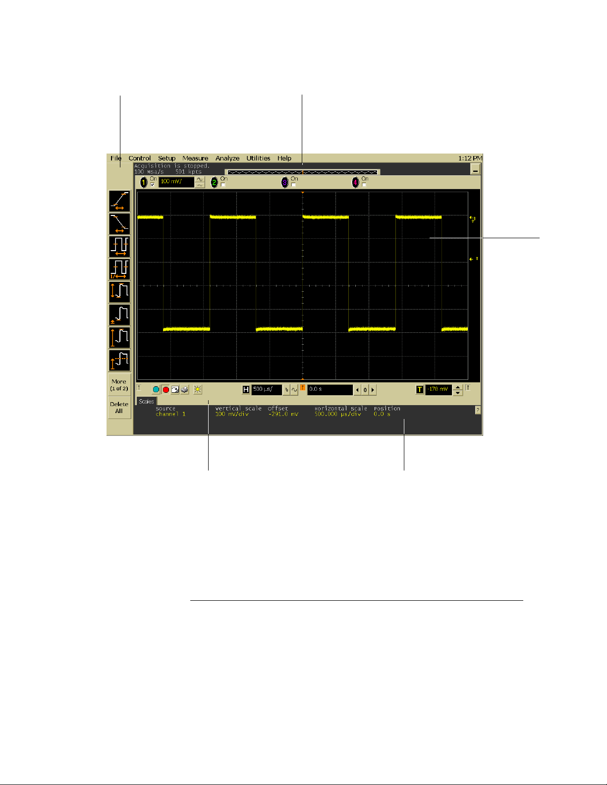
Figure 3-23
Right-click in this region
to see the Measurement
Setup context-sensitive
menu
Using the Oscilloscope
To select a command from a context-sensitive menu
Right-click in this region
to see the Acquisition
Setup context-sensitive
menu
Right-click in
the waveform
display area
to see the
waveform
contextsensitive
menu
Right-click in this region to see
the horizontal, trigger, and run
controls context-sensitive menu
Location of Context-Sensitive Menus
3-36
Right-click in this region to see
the context-sensitive menu for
the currently selected tab
Page 82

Figure 3-24
Using the Oscilloscope
To start and stop waveform acquisition
To start and stop waveform acquisition
• To start waveform acquisition, click the start button at the bottom of
the waveform display area.
• To stop waveform acquisition, click the stop button at the bottom of
the waveform display area.
See figure 3-24.
You can still use the Run and Stop keys on the front panel. However, if you are
performing many graphical interface operations, it is easier to start and stop the
oscilloscope using the buttons in the interface, so you do not have to remove
your hand from the mouse or stylus away from the touch screen.
Click this button
to start waveform
acquisition
Click this button
to stop waveform
acquisition
Start and Stop Icons
3-37
Page 83

Figure 3-25
Using the Oscilloscope
To clear the waveform display
To clear the waveform display
• Click the clear display button at the bottom of the waveform display.
See figure 3-25.
You can still use the Clear Display key on the front panel while the graphical
interface is enabled.
Clearing the display removes all displayed waveform data in preparation for
another acquisition. It also resets all automatic measurements and
measurement statistics.
Click this button to
clear the waveform
display
Clearing the Display
3-38
Page 84

Figure 3-26
Using the Oscilloscope
To print the screen
To print the screen
• Click the print button at the bottom of the waveform display.
See figure 3-26.
Infiniium prints the screen to the default printer according to the configuration
that you have selected in the Windows Control Panel.
Click this button to
print the screen
Printing the Screen
3-39
Page 85

Figure 3-27
Using the Oscilloscope
To change waveform brightness
To change waveform brightness
• Click the waveform brightness button at the bottom of the waveform
display.
See figure 3-27.
Click this button to change the
waveform brightness
Changing Waveform Brightness the Screen
3-40
Page 86

Figure 3-28
Turn a channel on by
clicking in the On
check box until a
check mark appears
Using the Oscilloscope
To turn a channel on or off
To turn a channel on or off
• To turn a channel on, click the check box next to the channel number
so that a check mark appears in the box. To turn a channel off, click
the check box again to clear it.
See figure 3-28.
If you are not using a channel, you can turn it off. This simplifies the waveform
display and also increases the display update rate. When you turn off a channel,
the current vertical scaling factor and vertical scale buttons for that channel
disappear. They re-appear when you turn the channel on.
You can also turn a channel on or off by using the Channel Setup dialog box, or
by using the front panel key for that channel.
Turn a channel off
by clicking in the
On check box until
the box is cleared
Turning a Channel On or Off
3-41
Page 87

Using the Oscilloscope
To adjust the vertical offset
To adjust the vertical offset
• Click and hold the left mouse button or touch screen stylus on the
waveform you want to move, then drag the pointer up or down to move
the waveform to the desired offset. Release when finished.
or
• Click and hold the left mouse button or touch screen stylus on the
ground reference indicator for the waveform you want to move, then
drag the pointer to move the waveform to the desired offset. Release
when finished.
or
• Click the channel button in the vertical toolbar, then set the vertical
offset using the spin box control in the Channel Setup dialog box.
If you leave the mouse pointer on the waveform (without clicking), the pointer
changes into crossed arrows as a visual indicator that you can drag the waveform
when you click and hold. If you move the crossed arrow pointer up or down,
the interface constrains the movement vertically and adjusts vertical offset only.
If you initially move the crossed arrow pointer left or right, the interface
constrains the movement horizontally and changes the horizontal position
setting only.
You can also adjust the vertical offset through the Channel Setup dialog box.
See “To access the channel setup” on page 3-45.
3-42
Page 88

Figure 3-29
Using the Oscilloscope
To adjust the vertical offset
Click to access the
Channel Setup dialog,
then set vertical offset
using the spin box or
numeric keypad...
...or click on the
ground reference
indicator and drag it
up or down to
change the vertical
offset...
Adjusting Vertical Offset
...or click on the
waveform and
drag it up or down
to do the same
thing.
3-43
Page 89

Figure 3-30
Using the Oscilloscope
To adjust vertical scaling
To adjust vertical scaling
• To make the waveform bigger, click on the larger waveform button next
to the channel number near the top of the display. To make the
waveform smaller, click on the smaller waveform button.
See figure 3-30. The number of volts per division decreases.
The number of volts per division increases. The current setting in volts per
division is shown next to the waveform buttons for the channel. Notice that the
setting is color-coded to match the waveform color for easy recognition.
You can also adjust the vertical scaling by clicking on the current setting, which
is shown next to the waveform buttons for the channel. This displays a pop-up
numeric keypad that allows you to set an exact value for the scaling. Or, you
can adjust the vertical scaling through the Channel Setup dialog box. See “To
access the channel setup” on page 3-45.
Click to display a pop-up
numeric keypad that lets you
specify a particular vertical
scaling value
Click to make the
waveform bigger
(fewer volts per
division)
Adjusting Vertical Scaling
3-44
Click to make the
waveform smaller
(more volts per
division)
Page 90
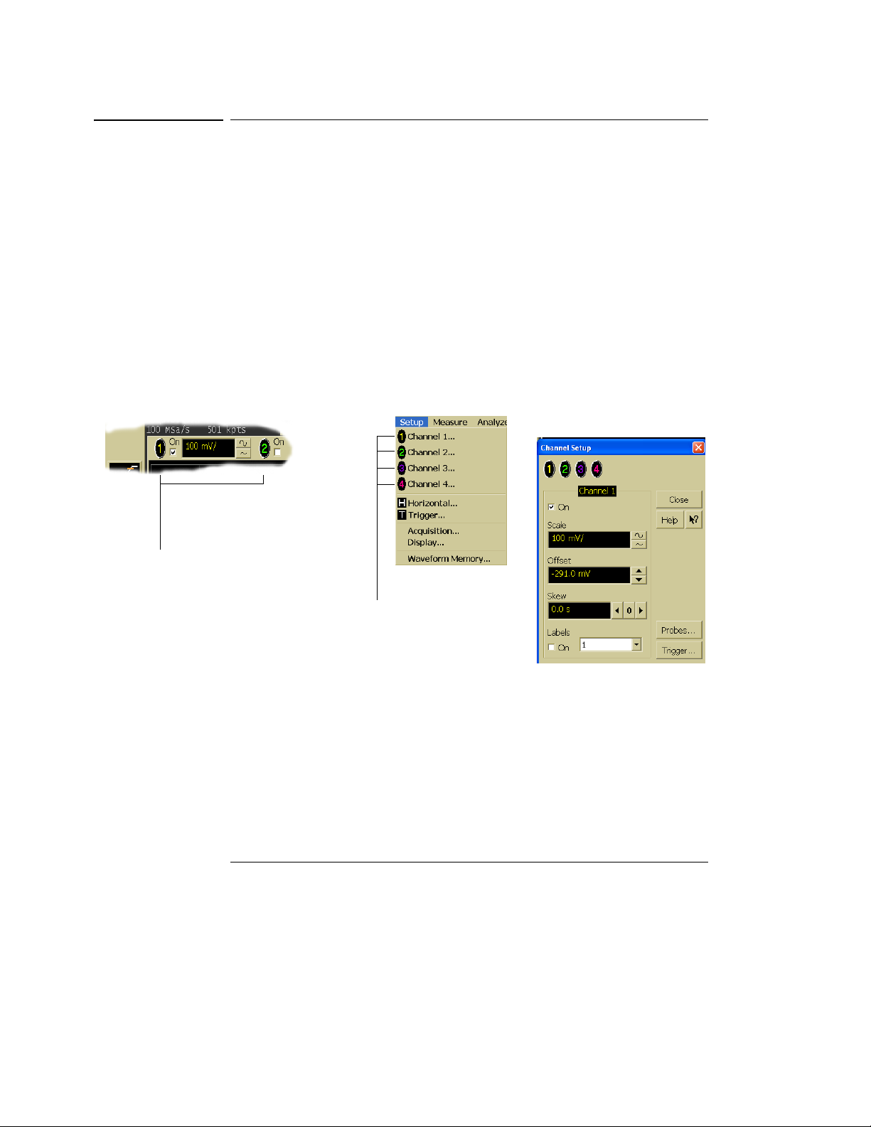
Figure 3-31
Using the Oscilloscope
To access the channel setup
To access the channel setup
• Click the channel number button at the top of the waveform display.
or
• Select the desired channel from the Setup menu.
With the channel setup dialog, you can set the vertical scaling, offset, input
coupling, and input impedance. It also lets you specify the characteristics of
the probe, using the Probes button. You can set attenuation ratio, attenuation
units, and measurement units for the probe, or perform a probe calibration. For
Agilent Technologies probes that are compatible with the AutoProbe Interface,
the oscilloscope will automatically set these characteristics (except for skew)
after identifying the probe when it is connected to the channel input.
Click one of the
channel buttons at
the top of the
waveform display...
Accessing the Channel Setup
...or select a
channel from
the Setup
menu...
...to access the channel
setup dialog box.
3-45
Page 91

Figure 3-32
Using the Oscilloscope
To set the horizontal reference point
To set the horizontal reference point
• Click on one of the arrows at the bottom of the waveform display.
The selected horizontal reference is highlighted.
The vertical arrows at the bottom of the display correspond to the left, center,
and right horizontal reference points. This is the position of the trigger if the
horizontal position is set to zero delay. A non-zero horizontal position value is
the time relative to the trigger event at the selected horizontal reference point.
Click to set the
horizontal reference
to the left side of the
display
Horizontal Reference Points
3-46
Click to set the
horizontal reference
to the center of the
display
Click to set the
horizontal reference
to the right side of the
display
Page 92

Figure 3-33
Using the Oscilloscope
To adjust sweep speed
To adjust sweep speed
• To stretch the waveform horizontally, click the larger waveform button
next to the horizontal sweep speed setting at the bottom of the
waveform display. To shrink the waveform horizontally, click the
smaller waveform button.
See figure 3-33. The oscilloscope decreases or increases the number of seconds
per division based on your selection.
You can also adjust the sweep speed by clicking on the current setting. This
displays a pop-up numeric keypad that allows you to set an exact value for the
sweep speed. Or, you can adjust the sweep speed through the Horizontal Setup
dialog box. See “To access the horizontal setup” on page 3-49.
Click here to
display the
horizontal
setup dialog
box
Click here to set
the sweep
speed directly
through a popup numeric
keypad
Adjusting Sweep Speed
Click to shrink
the waveform
(more
seconds per
division)
Click to stretch the
waveform (fewer
seconds per
division)
3-47
Page 93

Figure 3-34
Using the Oscilloscope
To adjust horizontal position
To adjust horizontal position
The horizontal position is the time relative to the trigger at the highlighted
horizontal reference point.
• To zero the horizontal position, click the 0 button next to the position
value at the bottom of the waveform display.
This will position the trigger event at the highlighted horizontal reference point.
• To move the waveform to the right or left, click the right or left arrow
next to the position value at the bottom of the waveform display. Or,
click and hold the mouse button on the desired waveform and drag the
waveform to the right or left. Release the mouse button when the
waveform is in the desired position.
When you click and drag a waveform, this changes the horizontal position for
all channels and functions on the display, but not that of waveform memories.
You can also adjust the horizontal position through the horizontal setup dialog.
Click to set the
horizontal position
through a pop-up
numeric keypad
Adjusting Horizontal Position
3-48
Move the
waveform
to the left
Reset the
horizontal
position to
zero
Move the
waveform to
the right
Page 94
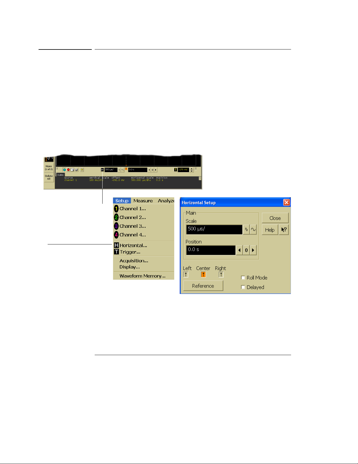
Figure 3-35
Using the Oscilloscope
To access the horizontal setup
To access the horizontal setup
• Click the horizontal setup button at the bottom of the waveform display.
or
• Select Horizontal from the Setup menu.
See figure 3-35.
Using the Horizontal Setup menu, you can set sweep speed, position, and the
horizontal reference. You can also set up the delayed time base window, which
uses software expansion to present a magnified view of an area of the waveform.
See the built-in information system (described in chapter 4) for details.
Click this
button...
...or select this
menu item...
Accessing the Horizontal Setup
...to access the horizontal
setup dialog box.
3-49
Page 95

Using the Oscilloscope
To zoom on a section of the waveform
To zoom on a section of the waveform
1 Click and hold the left mouse button or touch screen stylus in a blank
space within the waveform display area, then drag the pointer to draw
a rectangle around the areas of interest on the waveform(s) then
release.
2 Click once anywhere inside the rectangle drawn in step 1.
How the zoom takes place depends on whether acquisition is running or
stopped. If running, the oscilloscope adjusts vertical scale, vertical offset, sweep
speed, and horizontal position as necessary to best rescale the area you defined
in step 1. If stopped, the oscilloscope does a software magnification of the
waveform.
In either case, a small dialog box appears in the corner of the screen, with an
“Undo” button; by clicking this button, you will undo the zoom and return the
oscilloscope to its previous settings.
Avoid Overdriving the Vertical Input Amplifiers
When the oscilloscope is running, the input waveform can overdrive the vertical
input amplifiers if you expand the vertical excessively. The result is distortion of
the waveform. Ensure that you select a region that will keep all of the waveform
on the screen vertically.
3-50
Page 96

Figure 3-36
Using the Oscilloscope
To zoom on a section of the waveform
Click and hold the
mouse button, drag
to create a selection
rectangle, then click
inside the rectangle
to zoom the display
on the waveforms
inside the rectangle
Zooming on a Section of the Waveform
3-51
Page 97

Using the Oscilloscope
To move the markers using the graphical interface
To move the markers using the graphical interface
1 Turn on the markers.
You can use the Marker A and Marker B keys on the front panel, or select
Markers from the Measure menu.
2 Click and hold the left mouse button or touch screen stylus while the
mouse pointer is on one of the markers, then drag the marker to the
position you want on the waveform then release.
Clicking and dragging a marker makes it easy to quickly move the marker to the
desired waveform event. You can use the front-panel arrow keys for fine
adjustment. Or, you can select the Markers command from the Measure menu
and set the marker position precisely. See the built-in information system for
details.
3-52
Page 98

Figure 3-37
Using the Oscilloscope
To move the markers using the graphical interface
To move a
marker,
click the left
mouse
button or
touch
screen
stylus with
the pointer
on the
marker, drag
the marker
to the new
position,
then release
Moving the Markers
3-53
Page 99

Using the Oscilloscope
To make a measurement on a waveform
To make a measurement on a waveform
• Click and hold the mouse button or touch screen stylus on a
measurement icon, then drag the icon to the waveform event you want
to measure then release.
or
• Click on a measurement icon, then specify which source you want to
measure in the dialog box that is displayed.
For measurements on waveform features, such as those that involve waveform
edges, if you click the measurement icon and specify a source, the measurement
defaults to using the feature closest to the horizontal reference point. When
you make the measurement using drag-and-drop, the measurement uses the
waveform feature closest to the point where you drop the icon.
Only the most commonly used measurements are available on the toolbar.
Others are available by selecting them from the Measure menu. A few
specialized measurements are available only through the GPIB programming
command set to the oscilloscope. See the Programmer’s Reference.
When you drag and drop a measurement icon on a waveform, notice that the
icon outline changes color to match the color of each waveform it touches. This
enables you to easily see which waveform will be measured when you release.
Also, the measurement results are also displayed in color to make it easy to see
which waveform source is being measured.
For edge-sensitive measurements, when you drop the measurement icon on a
waveform, a geometric icon appears in the waveform marker color. This icon
shows exactly where the measurement is being made. The icon is also displayed
next to the measurement results readout to associate the readout with the
waveform and feature being measured. See figure 3-38. This feature helps you
distinguish measurement results from each other when you make multiple
measurements on the same waveform, but at different waveform features. For
example, a series of rise time measurements on several different edges of the
same waveform all have unique geometric icons to show each measurement’s
location.
3-54
Page 100

Figure 3-38
Channel numbers
associate the
measurement
results with the
channel waveform
being measured.
Using the Oscilloscope
To make a measurement on a waveform
Waveform Measurements
In some cases, geometric icons
are also displayed to associate the
measurement results with the
location on the waveform being
measured.
3-55
 Loading...