

Page 1

Agilent Technologies Infiniium 90000 X-Series Oscilloscopes
Data Sheet
Engineered for 33 GHz true analog bandwidth that delivers
Featuring Agilent’s PrecisionProbe
Page 2

Engineered for 33 GHz true analog bandwidth that delivers:
Need bandwidth?
When you’re deploying leading edge high-speed serial bus
designs like FibreChannel, SAS 12 G, or 10 Gb Ethernet
KR, jitter matters and picoseconds count. When you’re
doing spectral analysis of wide-bandwidth RF signals or
investigating transient phenomena, bandwidth is critical.
You need the most accurate real-time oscilloscope you can
get. Agilent Infiniium 90000 X-Series scopes are engineered
for 33 GHz true analog bandwidth that delivers:
• The industry’s highest real-time scope measurement
accuracy
• The industry’s only 30 GHz oscilloscope probing system
• The industry’s most comprehensive application-specific
measurement software
33 GHz true analog bandwidth
The quest for higher real-time scope bandwidth involves
pushing against the physical limitations of state-of-theart integrated circuit technology. We define true analog
bandwidth as performance achieved directly through the
hardware of the real-time oscilloscope, and we’ve achieved
breakthrough performance of 33 GHz with the Infiniium
90000 X-Series. Other vendors, limited to 16 GHz hardware,
employ various techniques to boost the bandwidth
specification of their scopes. However, these methods
introduce noise and distortions that negatively impact
measurements.
Custom front end technology requiring over five years of design
effort yields the fastest real-time oscilloscope hardware available
today.
With the Agilent Infiniium 90000 X-Series oscilloscopes,
you get the unmatched combination of the world’s fastest
real-time oscilloscope and the best measurement accuracy.
Analog bandwidth Sample rate Max Memory
Model number 2 channel 4 channel 2 channel 4 channel depth 4 channel
DSA-X93204A 33 GHz* 16 GHz 80 GSa/s 40 GSa/s 2 Gpts
DSA-X92804A 28 GHz 16 GHz 80 GSa/s 40 GSa/s 2 Gpts
DS0-X92804A 28 GHz 16 GHz 80 GSa/s 40 GSa/s 2 Gpts
DSO-X92504A 25 GHz 16 GHz 80 Gsa/s 40 GSa/s 2 Gpts
DSA-X92504A 25 GHz 16 GHz 80 Gsa/s 40 GSa/s 2 Gpts
DSO-X92004A 20 GHz 16 GHz 80 Gsa/s 40 GSa/s 2 Gpts
DSA-X92004A 20 GHz 16 GHz 80 Gsa/s 40 GSa/s 2 Gpts
DSO-X91604A 16 GHz 16 GHz 80 Gsa/s 40 GSa/s 2 Gpts
DSA-X91604A 16 GHz 16 GHz 80 Gsa/s 40 GSa/s 2 Gpts
2
BW Upgradeable
Buy the performance
you need today
knowing you have the
headroom you need
for tomorrow with
bandwidth upgradability
to 33 GHz
Page 3

Engineered for 33 GHz true analog bandwidth that delivers:
The industry’s highest real-time scope measurement
accuracy.
When you’re designing with faster signals, shrinking eyes
and tighter jitter budgets mean that error introduced by
your oscilloscope can seriously impact your measurement
results. The Agilent Infiniium 90000 X-Series scopes deliver
the highest measurement accuracy available by offering the
following industry-leading characteristics:
• Highest true analog bandwidth (33 GHz)
• Lowest oscilloscope noise floor (2.25 mV at 50 mV/div,
33 GHz)
• Lowest jitter measurement floor (150 fs)
Having the highest analog bandwidth, and lowest noise floor
available means better spectral analysis of transients and
wide-bandwidth RF signals.
Industry’s first and only 30 GHz oscilloscope probing
system.
No matter how good your scope is, if your probes can’t
operate at sufficient bandwidths your measurements are
compromised. The Agilent Infiniium 90000 X-Series scopes
offer probing solutions that are up to the tough challenges
of high-speed signal capture with the following:
• InfiniiMax III high frequency probes with automatic
AC calibration (PrecisionProbe)
• Fully-integrated probe amplifier s-parameter
correction
• The industry’s first bandwidth-upgradable probe
amplifier
Easily isolate signals of interest with zone qualified view
using InfiniiScan software triggering, just one of over
40 application-specific software options
The industry’s most comprehensive applicationspecific measurement software.
When time is of the essence, you need tools that can speed
true understanding of your signal activity. From serial bus
debug and compliance testing to jitter measurements to
sophisticated triggering capability, Agilent stays on top of
the test standards and your requirements by working to
ensure that you get accurate results more quickly. The
Agilent Infiniium 90000 X-Series scopes offer the following
• The broadest range of jitter, triggering, analysis and
display tools
• Pre-built compliance testing software based on the
expertise of our engineers on the standards committees
• Support for emerging technologies including
FibreChannel, SAS 12G, or MIPI-MPhy
3
Page 4

Engineered for 33 GHz true analog bandwidth that delivers:
33 GHz true analog bandwidth of the
oscilloscope and 80 GSa/s sample rate
provides ultra-low noise
See your signal more clearly with a 12.1-inch
XGA (1024 x 768) high-resolution color touch
screen display
Identify anomalies easily with a 256-level
intensity-graded or color-graded persistence
display that provides a three dimensional view
of your signals
Live indicator shows when the scope is
running a long operation.
Remote access through 10/100/1000 BaseT
LAN interface with web-enabled connectivity
uses ultra-responsive Ultra VNC.
Capture your longest signal with up to
25 ms data using 2 Gpt of acquisition
memory at 80 GSa/s.
GPIB and LAN provide remote measurements.
Optional Infiniium application remote program
interface allows application/compliance
software automation. LXI class C compliant.
MATLAB support.
Removable hard disk drive option is available
for added data security.
Calibration edge with a rise time of less
than 15 ps enables TDT calibration with
PrecisionProbe software.
Threaded RF connectors ensure the most reliable signal integrity
for high-performance instruments. The Autoprobe II interface
combines the tried-and-true, robust 3.5 mm threaded RF connector
of Agilent sampling scopes with a convenient automatic torque
mechanism (clutch) that ensures a consistent 8 in. lbs. connection
is made without the hassles of a torque wrench.
4
Page 5

Simply press the horizontal delay knob to
set the delay value to zero. A zoom button
provides quick access to two screen zoom
mode.
10 MHz reference clock can be input to
or output from the scope to allow precise
timebase synchronization with more than
one oscilloscope, RF instruments or logic
analyzers
Dedicated single acquisition button provides
better control to capture a unique event
Customizable multipurpose key gives you any
five automated measurements with a push
of a button. You can also configure this key
to execute a script, print/save screen shots,
save waveforms or load a favorite setup.
Measure section, including a toggling marker
button and a dedicated marker knob, provides
quick access to your marker control.
Quick access to fine/vernier control by
pressing the horizontal and vertical sensitivity
knobs.
Optional x4 PCIExpress slot speeds up offload times by
a factor of 5, using socket drivers. Use this option (823)
for faster deep offloads of the waveforms.
Increase your productivity with a familiar
Infiniium graphical user interface, including
your favorite drag-and-drop measurement
icons. Infiniium’s analog-like front panel
has a full set of controls color-coded to the
waveforms and measurements, making your
tasks simple.
Three front panel USB 2.0 host ports match
your USB keyboard, mouse, and USB memory
drive connection for saving setup and data
files and screen shots.
An additional four USB 2.0 host ports and a
USB 2.0 device port on the back panel. Perfect
for extra connectivity including an optical
drive. A USB 2.0 device port lets you control
the scope and transfer data via a USB 2.0 480Mbpts connection.
5
Page 6

Engineered for 33 GHz true analog bandwidth that delivers:
The highest real-time scope measurement accuracy
Whether you’re deploying emerging high speed bus
technology, identifying spectral content of wide-bandwidth
RF signals, or analyzing transient physical phenomena, you
need the truest representation of your signals under test.
Agilent invested in leading edge technology to bring you
the highest real-time oscilloscope measurement accuracy
available today.
New custom integrated circuits using a proprietary Indium
Phosphide (InP) process and breakthrough packaging
technology enable industry-leading performance, including
the:
• Highest true analog bandwidth
• Lowest oscilloscope noise floor
• Lowest oscilloscope jitter measurement floor
Highest true-analog bandwidth- 33 GHz
The engineering of a high-performance real-time oscilloscope
front end requires designing pre-amplifiers, triggering
capability, and sampling technology. But putting it all together
might be the toughest challenge. Using fine line microcircuit
processes and relying extensively on years of experience with
RF design, Agilent developed the front end multi-chip modules
shown here for the Infiniium 90000 X-Series oscilloscopes.
Packaging technology provides excellent high-frequency
electrical properties along with superior heat dissipation. It
enables the highest true analog bandwidth available today in
real-time oscilloscopes.
Industry’s lowest noise floor.
One of the keys to measurement accuracy at high
bandwidths is minimizing the noise generated by the
oscilloscope itself. Agilent utilizes a proprietary Indium
Phosphide (InP) integrated circuit process in the design of
the Infiniium 90000 X-Series oscilloscopes because other
oscilloscope techniques just can’t deliver the necessary
combination of high-bandwidth and low noise. Not only
does that mean you’re purchasing the best tool today,
but it also means you can count on technology leadership
from Agilent in the future.
6
Page 7

Engineered for 33 GHz true analog bandwidth that delivers:
The highest real-time scope measurement accuracy
Industry’s lowest real-time oscilloscope jitter
measurement floor
Oscilloscope bandwidth allows signal rise times to be
more accurately depicted. The oscilloscope noise floor
directly impacts the y-axis voltage placement of each signal
data point. The Infiniium 90000 X-Series scopes combine
superiority in these characteristics with extremely low
sample clock jitter (< 150 femptoseconds). This ensures the
lowest possible contribution to jitter measurements from
the scope itself so you’re using your jitter budget on your
design.
In addition to its low jitter measurement floor, the 90000
X-Series has the industry’s deepest memory with up
to 2 Gpts, allowing you to resolve low frequency jitter
components in a single measurement.
Jitter measurement floor of less than 150 fs
How much better is our jitter measurement?
We made measurements on multiple sine waves from
an Agilent signal generator. We compared the Agilent
Infiniium 90000 X-Series scope to DSP boosted
oscilloscopes from our competitor.
The results show that the 90000 X-Series consistently makes
significantly (up to 10x) lower jitter measurements than its competitor.
7
Page 8

Engineered for 33 GHz true analog bandwidth that delivers:
Industry’s first 30 GHz oscilloscope probing system
To take advantage of your investment in a high bandwidth
oscilloscope, you must have a probing system that can
deliver bandwidth to the probe tip. Agilent rises to the
challenge of high speed signal reproduction with these
probing innovations:
The InfiniiMax III 30 GHz probing system includes accessories to enable probing with a ZIF tip, browsing, or connecting
to 3.5 mm inputs.
• The industry’s first bandwidth upgradable probe
amplifier
• Fully-integrated probe amplifier s-parameter correction
Model Description
N2803A 30 GHz probe amp
N2802A 25 GHz probe amp
N2801A 20 GHz probe amp
N2800A 16 GHz probe amp
PrecisionProbe
Agilent’s PrecisionProbe uses its 200 GHz indium phosphide
process to create a fast edge for characterization
with PrecisionProbe.
8
Agilent’s N2809A PrecisionProbe software quickly
characterizes and compensates the frequency response
of any path to the 90000 X-Series input. PrecisionProbe’s
patented technology uses the <15ps edge from the 90000
X-Series oscilloscope to:
• Measure input impedance and response of any probe
and the loss of any cable
• Quickly correct from probe and cable loss(without extra
instruments such as VNA or TDR)
• Correct probing issues such as phase nonlinearity,
magnitude non-flatness, and see the effect of probe
loading
• Quickly gain insight into impedance/capacitance that
defines your connection
Page 9

Engineered for 33 GHz true analog bandwidth that delivers:
Industry’s first 30 GHz oscilloscope probing system
Fully-integrated probe amplifier s-parameter
correction
Each InfiniiMax III probe amplifier comes pre-packaged with
its own customized characteristics via s-parameter files.
The InfiniiMax III probing system and the 90000 X-Series
communicate via an I2C bus. This communication allows
the 90000 X-Series to download the customized s-parameter
files from the InfiniiMax III probing amplifier to the scope for
greater accuracy.
The InfiniiMax III probing system uses the same InP technology that enables high bandwidth
and low noise oscilloscope measurements.
Industry’s only bandwidth upgradable probes
Purchase the probing performance you need today with
confidence that you have headroom for the future with
Agilent’s InfiniiMax III bandwidth upgradable probes.
Upgrade to higher performance at a fraction of the cost of
new probes as your needs evolve.
Bandwidth upgrades
N5471F 13 GHz 90000A to 16 GHz 90000 X-Series
N5471G 16 GHz to 20 GHz Bandwidth Upgrade
N5471H 20 GHz to 25 GHz Bandwidth Upgrade
N5471I 25 GHz to 28 GHz Bandwidth Upgrade
N5471J 28 GHz to 33 GHz Bandwidth Upgrade
9
Page 10

Engineered for 33 GHz true analog bandwidth that delivers:
The industry’s most comprehensive application-specific measurement software
To get the most out of your Agilent Infiniium 90000 X-Series
oscilloscope, choose from a wide array of application
specific software options that speed your measurement
tasks including:
• A broad range of jitter, triggering, measurement,
analysis and display tools
A broad range of jitter, trigger, measurement,
analysis, and display tools
When time is of the essence you need your scope to
acquire and present data in the most usable form so
you can get to answers quickly.
The Agilent Infiniium 90000 X-Series oscilloscopes offer
the industry’s widest range of supporting software with
an intuitive interface to simplify learning curves. We’ve
highlighted some of our most popular tools here, and the
complete list follows on the next pages.
• Pre-built compliance testing software based on the
expertise of our engineers on the standards committees
• Support for emerging high speed serial buses including
SAS 12G, FibreChannel, and PCIeTM gen3.
Quickly characterize jitter and display histograms, measurement
trending, and jitter spectrum.
Agilent’s InfiniiSim waveform translation toolset provides
efficient de-embedding of probe and circuit element loading,
enables measurement translation from accessible probe points
to other locations in the system, and simulates waveforms with
channel models inserted. Combine measurements and models
for accurate characterization of design performance, all done
with hardware acceleration for fast update rates.
Not just a tool for the digital world
Infiniium built-in FFT allows users to quickly and easily
analyze the frequency components of their signals. Both
FFT magnitude and phase can be displayed and can be
combined with other built-in math functions or MATLAB®
based measurements. Standard windowing of Hanning,
Blackman Harris, Flattop and Rectangular are supported
along with cursor based power measurements. When more
powerful frequency domain measurements are required,
including modulation analysis, consider the Agilent 89601A
Vector Signal Analyzer software.
10
Page 11

Engineered for 33 GHz true analog bandwidth that delivers:
The industry’s most comprehensive application-specific measurement software
Pre-built compliance testing software with Agilent
expertise
Choose from the industry’s widest range of complete
applications for compliance and margin testing for high
speed serial buses, including SATA, SAS, PCI Express,
Ethernet, USB, JEDEC and more. Agilent’s measurement
experts sit on the industry standards committees and help
define compliance requirements. They ensure that our tools
deliver to the standards. Set up wizards combined with
intelligent test filtering give you confidence you’re running
the right tests. Comprehensive HTML reports with visual
documentation and pass/fail results guarantee that critical
information is retained on each test. Technicians can run
complete and accurate testing on their own, freeing valuable
engineering resources.
Support for proprietary and emerging high speed
serial buses
Agilent engineers hold key positions within the governing
bodies defining test requirements for interoperability on
emerging high speed serial buses. We provide tools as
quickly as possible on emerging standards.
User Defined Application software allows automated
compliance testing on proprietary buses or while
emerging test standards solidify.
Rapidly develop automated measurements for compliance
testing with Agilent’s User Defined Application software.
This tool provides the framework you need to quickly
program and automate any set of measurements with an
interface similar to that provided in our standard compliance
test software. Full control of other Agilent instrumentation is
possible, along with automated HTML reporting capabilities
Applications are available today for:
• MIPI M-Phy
• MDDI
• GDDR5
• SAS 6G
11
Page 12

Engineered for 33 GHz true analog bandwidth that delivers:
The industry’s most comprehensive application-specific measurement software:
measurement,
Trigger on and decode CAN, LIN and FlexRay serial packets
EZJIT analysis software (E2681A or option 002 on new
scope purchases)
analysis and decode software packages
CAN. LIN and FlexRay triggering and decode
(N28803A or Option 063 on new scope purchases)
Trigger on and view both protocol layer information and
physical layer signal characteristics for CAN, LIN and
FlexRay buses. Numerical decode values are automatically
displayed and synchronized below the captured signal or
seen in protocol viewer.
Hardware-based triggering for CAN and LIN means
triggering reliably, even on the most infrequent events.
FlexRay uses software-based protocol triggering.
This application works on all models and can use any
combination of scope and logic acquisition channels.
For more information: www.agilent.com/find/N28803A
Quickly characterize and evaluate most commonly needed jitter
measurements, including cycle-cycle, N-cycle, period, timeinterval, error, setup and hold time, histograms, measurement
trending and jitter spectrum.
This application is supported on all models and is standard on
DSA models.
For more information: www.agilent.com/find/EZJIT
Easily separate the spread spectrum clock using EZJIT analysis
software.
PrecisionProbe software (N2909A or Option 001 on new
scope purchases)
Make more accurate measurements independent of what probes
or cables used. Agilent’s N2909A PrecisionProbe software
characterizes and corrects for the loss in your specifi c cable
or probe. PrecisionProbe removes the uncertainty about the
input connected to your oscilloscope by allowing you to see its
characteristics in less than fi ve minute. PrecisionProbe gives
you design and debug confi dence by allowing you to quickly
de-embed probe and cable loss to make more accurate measurements.
Quickly characterize and correct for any input to your oscilloscope.
12
For more information: www.agilent.com/find/PrecisionProbe
Page 13

Engineered for 33 GHz true analog bandwidth that delivers:
The industry’s most comprehensive application-specific measurement software:
measurement,
Analyze jitter plus RJ/DJ separation.
High-speed serial data analysis software (E2688A or
Option 003 on new scope purchases)
analysis and decode software packages
EZJIT Plus analysis software (N5400A or Option 004 on
new scope purchases. To upgrade from EZJIT to EZJIT
Plus, order N5401A.)
EZJIT Plus adds additional compliance views and an expanded
measurement setup wizard to simplify and automate RJ/DJ
separation for testing against industry
standards.
This application is supported on all models and is standard on
DSA models.
For more information: www.agilent.com/find/EZJITPlus
Quickly validate signal integrity for high-speed serial interfaces
with embedded clocks. Recover embedded clocks
synchronized with the analog waveform view. Build and validate eye diagrams.
The SDA package also includes software-based bit-level
triggering and decode for 8B/10B. This application is supported
on all models and comes standard on DSA models.
For more information: www.agilent.com/find/SDA
Recover embedded clocks with serial data analysis (SDA).
13
Page 14

Engineered for 33 GHz true analog bandwidth that delivers:
The industry’s most comprehensive application-specific measurement software:
measurement,
Trigger and view on-screen serial decode of I2C packets
analysis and decode software packages
I2C/SPI serial trigger and decode (N5391A or Option
007 on new scope purchases)
Given even futher insights with protocol decode capability.
Quickly move between physical and protocol layer
information using the time-correlated tracking marker.
Display protocol content using waveform symbols and the
industry’s first multi-tab protocol viewer. The packets tab
shows a high level view of the packet over time.
Infi niiScan event identifi cation featuring zone-qualify
triggering
(N5415B or Option 009 on new scope purchases)
Rapidly trigger on complex events and identify signal
integrity issues. This innovative software quickly scans through
thousands of acquired waveform cycles and isolates anomalous
signal behavior.
For more information: www.agilent.com/find/infiniiScan
Identify signal integrity issues with Infi niiScan Zone – Qualify triggering.
14
Page 15

Engineered for 33 GHz true analog bandwidth that delivers:
The industry’s most comprehensive application-specific measurement software:
measurement,
Model channel effects including refl ection.
Infi niium serial data equalization (N5461A or Option
012 on new scope purchases)
analysis and decode software packages
Infi niiSim waveform transformation toolset (N5465A or
option 013, and 014 on new scope purchases)
Use theInfi niiSim toolset to combine measurements and
models to view simulated scope measurement results at any
location in your design. Import design models (s-parameters or
transfer functions), acquire real-time scope data, and transform to measurement locations you need.
Model single element systems such as de-embedding or
embedding a cable or fi xture with the basic Infi niiSim toolset.
Choose ‘advanced’ for more extensive modeling of complex
systems such as multiple element and probed systems.
For more information: www.agilent.com/find/InfiniiSim
Measure at the pin and use equalization to see a virtual eye on
the other side of an equalizer. Model equalization techniques
such as DFE, FFE, and CTLE.
For more information: www.agilent.com/find/SDE
Reduce receiver errors by opening tightly shut eyes.
15
Page 16

Engineered for 33 GHz true analog bandwidth that delivers:
The industry’s most comprehensive application-specific measurement software:
measurement,
Make customized or automated measurements using MATLAB software
analysis and decode software packages
MATLAB® data analysis software (Option 061 or 062 on
new scope purchases)
MATLAB is a data analysis software environment and scripting
language used by over 1,000,000 users in aerospace/defense,
automotive, communications, electronics, and other applications. MATLAB is now available directly from Agilent as in
instrument option with the purchase of your Agilent 90000-X
Series oscilloscope. Install MATLAB on your oscilloscope or
remote PC to make customized measurements, design and apply your own fi lters to oscilloscope signals, graphically visualize
signals in 2-D or 3-D plots, automate measurements, or build
test applications. Purchase MATLAB with your Agilent 90000-X
Series oscilloscope to ensure version compatibility and so that
your MATLAB software license is always available when you
need it.
For more information:
www.agilent.com/find/matlab_oscilloscopes
MIPI D-phy trigger and decode (N8802A or Option 019 on new
scope purchases)
This application eliminates the need to manually decode bus
traffi c. Using data captured on the scope, the application lets
you easily view the information sent over MIPI serial buses.
The application also enables software based protocol triggering.
For more information: www.agilent.com/find/N8802A
Trigger and view on-screen serial decode of MIPI traffic
16
Page 17

Engineered for 33 GHz true analog bandwidth that delivers:
The industry’s most comprehensive application-specific measurement software:
measurement,
Trigger on and decode PCIe serial packets.
analysis and decode software packages
PCI Express® serial trigger and protocol viewer (N5463A or
Option 017 on new scope purchases)
This application provides protocol-level triggering and viewing
of a PCIe® lane. Quickly view packets, payload, header, and
detail information. Powerful time-correlated views of waveform,
symbol, character, link and transaction layer packet data down
to the bit level make it easy to isolate communication faults to
logic or analog sources.
For more information:
www.agilent.com/find/90000_PCI_protocol_viewer
Remote programming interface (N5452A or Option 011 on
new scope purchases)
Operate your Infi niium compliance and validation applications
remotely using .NET languages.
For more information: www.agilent.com/find/RPI
Control your compliance applications remotely.
17
Page 18
Engineered for 33 GHz true analog bandwidth that delivers:
The industry’s most comprehensive application-specific measurement software:
measurement,
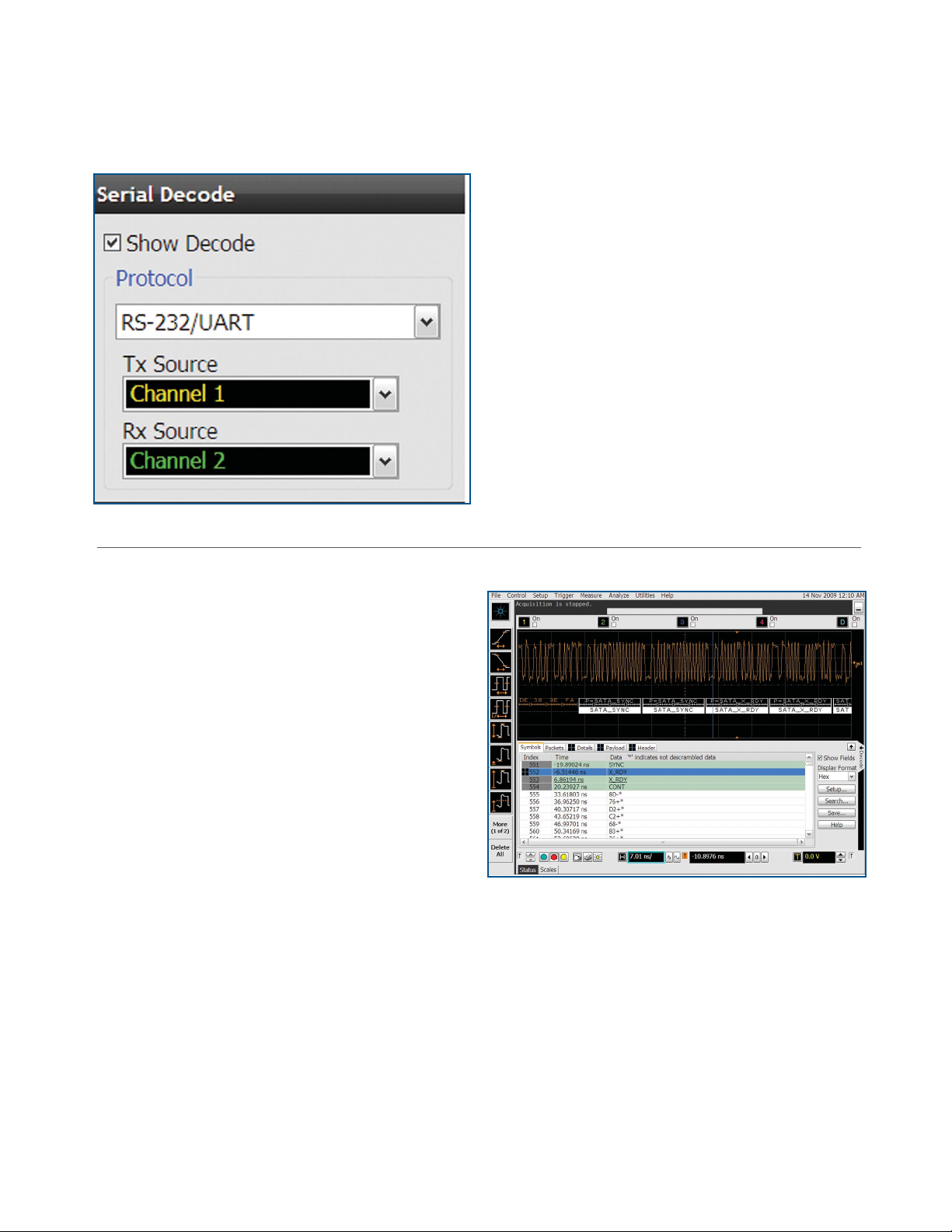
Trigger on and decode RS-232/UART transmission
analysis and decode software packages
RS-232/UART serial decode and trigger (N5462A or Option
015 on new scope purchases)
This application eliminates the need to manually decode bus
traffi c. Using data captured on the scope channels, the application lets you easily view the information sent over an RS-232
Display real-time time-aligned decode of transmit and receive
lines.
For more information: www.agilent.com/find/90000_RS-232
SATA/SAS triggering and decode (N8801A or option 018 on
new scope purchases)
Trigger on and view both protocol layer information and physical
layer signal
characteristics for SATA 1.5 Gb/s, 3.0 Gb/s, and 6.0 Gb/s.
Numerical decode values are automatically displayed and synchronizes below the capture signal or seen in protocol viewer.
For more information: www.agilent.com/find/N8801A
Trigger on and decode SAS/SATA serial packets.
18
Page 19

Engineered for 33 GHz true analog bandwidth that delivers:
The industry’s most comprehensive application-specific measurement software:
measurement, analysis and decode software packages
USB serial trigger and protocol viewer (N5464A or Option 016
on new scope purchases)
Trigger on and quickly view USB 2.0 packets, payload, header
and detail information. Powerful time-correlated views of
waveform and symbol, to the bit level, make it easy to isolate
communication faults.
For more information:
www.agilent.com/find/90000_USB_protocol_viewer
Trigger on and decode USB packets.
N8805A USB 3.0 Protocol Triggering and Decode (N8805A
or Option)
Trigger on and view USB 3.0 with the industry’s first
oscilloscope-based protocol analyzer with time-correlated
views of physical layer and transaction layer errors. The
multi-tab protocol viewer includes correlation between the
waveforms and the selected packet, enabling you to quickly
move between the physical and protocol layer using the
time-correlated tracking marker.
For more information:
www.agilent.com/find/usb3decode
Signal equalization using user-defi ned function.
Isolate signal integrity problems from logic-level coding errors on bidirectional serial data streams.
User-defi ned function (N5430A or Option 010 on new scope
purchases)
If we haven’t provided exactly what you need, use the N5430A
User Defi ned Function software to create it yourself. Develop
your own math functions or fi lters using MATLAB. Your custom
functionality is seamlessly integrated into the Infi niium 90000
menus and results are displayed on the scope screen. This requires MATLAB (available as Option 062) to be installed directly
on the oscilloscope. Agilent is the only T&M manufacturer
today that sells and supports MATLAB as its own product.
This application is supported on all models and requires MATLAB software (not included with UDF)
For more information: www.agilent.com/find/UDF
19
Page 20

Engineered for 33 GHz true analog bandwidth that delivers:
The industry’s most comprehensive application-specific measurement software:
compliance testing and validation software packages
DDR1 and LPDDR/DDR2 and LPDDR2/DDR3 compliance
testing (U7233A/N5413B/U7231A or Options 031/033/032 on
new scope purchases) or N5459A Option 001 for all memory
applications
Quickly and easily evaluate and characterize your memory
designs. Automated testing based on JEDEC specifi cations
saves time. The application also includes additional debug and
compliance capabilities.
This application is supported on all models. However, the DDR
technology you are using may dictate the minimal bandwidth
required for your scope.
For more information: www.agilent.com/find/DDR
Quickly validate DDR1/2/3 and LPDDR signals
DisplayPort compliance test software (U7232A or Option 028
on new scope purchases)
Sets the benchmark for ease-of-use, and offers complete
testing without compromise. The software guides the user
sequentially through the tasks ensuring minimal setup error,
executes the tests specifi ed by the standard and conveys the
test information through a convenient software generated
report. The three modes of physical layer test allow for automated measurements based on the customizable confi guration
of compliance and characterization testing. To make the test
signal connection, the Agilent W2641A DisplayPort test point
access adaptor completes the DisplayPort source solution.
Full suite of DisplayPort source tests.
For more information: www.agilent.com/find/U7232A
20
Page 21

Engineered for 33 GHz true analog bandwidth that delivers:
The industry’s most comprehensive application-specific measurement software:
compliance testing and validation software packages
HDMI Electrical performance validation and compliance software (N5399A or Option 023 on new scope purchases)
Quickly verify and debug your high defi nition multi-media
interface (HDMI) designs. The N1080A fi xture provides access
to the compliance points for the electrical measurements
required for the transmitter compliance testing.
For more information: www.agilent.com/find/N5399A
Verify and debug your HDMI designs.
MIPI D-PHY Compliance test software (U7238A or Option 035
on new scope purchases)
Automatically execute D-PHY electrical checklist tests for CSI
and DSI architectures. Displays the results in a fl exible report
format.
For more information:
www.agilent.com/find/d-phy_compliance
Automatically execute D-PHY electrical checklist
tests for CSI and DSI architectures.
21
Page 22

Engineered for 33 GHz true analog bandwidth that delivers:
The industry’s most comprehensive application-specific measurement software:
compliance testing and validation software packages
PCI Express® Electrical performance validation and
compliance software (N5393B or Option 022 on new scope
purchases)
Provides fast and easy way to verify and debug your PCI
Express designs. Allows you to automatically execute PCI
Express electrical checklist tests, and displays the results in a
fl exible report format. Ensures that your Gen2 measurements
will have absolute consistency with measurements made using
the PCI-SIG’s® standalone Sigtest software.
For more information: www.agilent.com/find/N5293B
Quickly verify and debug your PCI Express® designs
Serial attached SCSI (SAS) electrical performance
validation and compliance software (N5412A or Option 027
on new scope purchases)
Serial attached SCSI (SAS) electrical performance validation
and compliance software for Infiniium oscilloscopes
provides you with a fast and easy way to validate and
debug your SAS 1.5-Gbps (SAS 150) and 3.0-Gbps (SAS 300)
silicon, host bus adapter, initiator, high-density disk drive
or enclosure backplane. The SAS electrical test software
allows you to automatically execute SAS electrical checklist
tests at each of the IT, CT, IR and CR interface points, and
displays the results in a flexible report format. In addition
to the measurement data, the report provides a margin
analysis that shows how closely your device passed or
failed each test.
For more information: www.agilent.com/find/N5412A
Quickly validate and debug your SAS designs
22
Page 23

Engineered for 33 GHz true analog bandwidth that delivers:
The industry’s most comprehensive application-specific measurement software:
compliance testing and validation software packages
SATA 6G Compliance Test Software (N5411B or Option 038
on new scope purchases)
Rapidly validate and debug your SATA 1.5Gb/s (Gen 1),
3.0Gb/s (Gen2) and 6.0Gb/s (Gen3) silicon, host bus adapter,
port multiplier, high-density disk drive, solid-state disk drive
or optical disk drive. Provides automated compliance test
support for the i (internal), m(eSATA) and x(SAS attachment)
interfaces points, and displays the results in a fl exible report
format.
For more information: www.agilent.com/find/n5411b
Simplify the validation of SATA designs
USB 3.0 Compliance Test Software (U7243A or Option 041 on
new scope purchases
Provides industry leading automated test support for USB 3.0
products and displays the test results in a comprehensive test
report. For best measurement accuracy use the Agilent U7242A
USB 3.0 transmitter and receiver test fi xtures. Agilent’s USB 3.0
test solution is designed from the ground up with the needs of
the test engineer in mind.
For more information: www.agilent.com/find/USB3
Validate and debug your USB 3.0 silicon, host, hub or device
23
Page 24

Engineered for 33 GHz true analog bandwidth that delivers:
The industry’s most comprehensive application-specific measurement software:
compliance testing and validation software packages
User-defi nable application (N5467A or Option 040 on new
scope purchases)
Rapidly develop your own automated measurements and
tests.This application provides the framework you need to
quickly program and automate any single or set of measurements the oscilloscope can make. The application also provides
full control of other Agilent instruments and HTML reporting
capabilities.
For more information: www.agilent.com/find/UDA
Quickly automate oscilloscope measurements.
10GBASE-T Ethernet electrical conformance application for
Infi niium oscilloscopes (U7236A or Option 036 on new scope
purchases)
Takes care of the tedious task of instrument control and confi gures the oscilloscope, spectrum analyzer, or vector network
analyzer as needed by each 10GBASE-T test to provide rapid,
accurate, and repeatable test execution.
For more information: www.agilent.com/find/10gbase-t
Automatically execute 10GBASE-T Ethernet physical-layer
(PHY) electrical tests
24
Page 25

Agilent Infiniium Portfolio
Agilent’s Infiniium lineup includes bandwidths from 600 MHz
to 33 GHz. Use the following selection guide to determine
which best matches your specific needs.
Oscilloscope 9000 Series 90000 Series 90000-X Series
Type Real Time Real Time Real Time
Bandwidth 600 MHz to 4 GHz 2.5 GHz to 13 GHz 16 GHz to 33 GHz
Sampling Rate
(2 ch/4 ch)
Memory Depth Up to 1 Gpt Up to 1 Gpt Up to 2 Gpts
Size (H x W x D) 12.9” x 16.8” x 9”
Precision Probe NO YES to 13 GHz YES to 35 GHz
De-embedding YES YES YES
Data sheet 5990-3746EN 5989-7819EN 5990-5271EN
20/10 GSa/s 40/40 GSa/s 80/40 GSa/s
33cm x 43cm x 23cm
11.1” x 17” x 19.9”
28cm x 43cm x 51cm
10.5”x16.75”x18.7”
27cm x 43cm x 48cm
25
Page 26

Engineered for 33 GHz true analog bandwidth that delivers
Configure your high performance real-time oscilloscope solution today
Get the most out of your oscilloscope investment by choosing options and software to speed your most common tasks.
Configure your Infiniium X-Series oscilloscope in three easy steps. Use option numbers when ordering at time of purchase.
Use model numbers to add to an existing scope.
1. Choose your oscilloscope, memory and options
Mainframe:
Memory:
Oscilloscopes Description
DSAX93204A 33 GHz Signal Analyzer*
DSOX93204A 33 GHz Digital Signal Oscilloscope
DSAX92804A 28 GHz Signal Analyzer*
DSOX92804A 28 GHz Digital Signal Oscilloscope
DSAX92504A 25 GHz Signal Analyzer*
DSOX92504A 25 GHz Digital Oscilloscope
DSAX92004A 20 GHz Signal Analyzer*
DSOX92004A 20 GHz Digital Oscilloscope
DSAX91604A 16 GHz Signal Analyzer*
DSOX91604A 16 GHz Digital Oscilloscope
All models come with power cord, keyboard, mouse, stylus, calibration
cable, wrench and (5) coax adapters.**
*DSA models come with 50 Mpts memory, EZJIT, EZJIT+, and Serial Data Analyisis standard.
** 16 and 20 GHz models come with adapters rated to 25 GHz (1250-3758), all other models
come with adapters rated to 35 GHz (5061-5311)
Description Options Model number
20 Mpts/ch memory Standard N2810A-020
50 Mpts/ch memory DSOX90000A-050 N2810A-050
100 Mpts/ch memory DSOX90000A-100 N2810A-100
200 Mpts/ch memory DSOX90000A-200 N2810A-200
500 Mpts/ch memory DSOX90000A-500 N2810A-500
1 Gpts/ch memory DSOX90000A-01G N2810A-01G
2 Gpts/ch memory DSOX90000A-02G N2810A-02G
20 M memory standard, add option to increase to desired capacity
Options:
26
Description Options Model number
ANSI Z540 Compliant calibration DSOX90000-A6J
ISO17025 calibration DSOX90000-1A7
DVD RW DSOX90000-820 N5473A
GPIB Card-interface DSOX90000-805
PCI Express card-interface DSOX90000-823
Performance verification de-skew
fixture
Rack mount kit option DSOX90000-1CM N5470A
Removable hard drive with
Windows 7
Additional removeable hard drive
with Windows 7
DSOX90000-808 N5443A
DSOX90000-801
(requires option 801) N5474C
82350B
N4866A
Page 27

Engineered for 33 GHz true analog bandwidth that delivers
Configure your high performance real-time oscilloscope solution today
2. Choose your probes and accessories
Description Oscilloscopes
30 GHz InfiniiMax III probe amp N2803A
25 GHz InfiniiMax III probe amp N2802A
20 GHz InfiniiMax III probe amp N2801A
16 GHz InfiniiMax III probe amp N2800A
ZIF probe head N5439A
Browser (hand held) probe head N5445A
Solder-in probe head N5441A
3.5 mm/2.92-mm/SMA probe head N5444A
450 Ω ZIF tip replacement (set of 5) N5440A
250 Ω ZIF tip replacement (set of 5) N5447A
Browser tip replacement (set of 4) N5476A
PV/deskew fixture N5443A
Precision BNC adapter (50 ohm) N5442A
Sampling scope adapter N5477A
2.92 mm head flex cable N5448A
High impedance probe adapter N5449A
35 GHz cable N2812A
For more information about Agilent’s InfiniiMax III probing system, check out the
InfiniiMax III data sheet with the Agilent literature number, 5990-5653EN.
3. Choose your measurement-specific application software
Measurement, Analysis and
Decode Software Packages
Description Product number Model number
PrecisionProbe software DSOX90000-001 N2809A-001
CAN/FlexRay decode DSOX90000-063 N8803A
EZJIT jitter analysis software DSOX90000-002 E2681A
EZJIT Plus jitter analysis software DSOX90000-004 N5400A
High-Speed SDA and clock recovery DSOX90000-003 E2688A
2
C/SPI Decode DSOX90000-007
I
InfiniiScan software triggering DSOX90000-009 N5414B
InfiniiSim basic signal de-embedding DSOX90000-013 N5465A-001
InfiniiSim advanced signal de-embedding DSOX90000-014 N5465A-002
Serial data equalization DSOX90000-012 N5461A
MATLAB - Basic digital analysis package DSOX90000-061
MATLAB - Standard digital analysis package DSOX90000-062
MIPI D-PHY protocol DSOX90000-019
PCI-Express protocol DSOX90000-017
Remote programming interface DSOX90000-011 N5452A
RS-232/UART decode DSOX90000-015
SATA/SAS protocol DSOX90000-018 N8801A
USB protocol DSOX90000-016
User-defined function DSOX90000-010
Choose your application-specific software packages (see pages 12 to 19) for details.
N5391A
N8802A
N5463A
N5462A
N5464A
N5430A
27
Page 28

Engineered for 33 GHz true analog bandwidth that delivers
Configure your high performance real-time oscilloscope solution today
Compliance Testing and
Validation Software
Packages
Description Product Number Model number
DDR1 and LPDDR compliance DSOX90000A-031 U7233A
DDR2 and LPDDR2 compliance DSOX90000A-033 N5413B
DDR3 up to 1660 MHz compliance DSOX90000A-032 U7231A
DisplayPort compliance application DSOX90000A-028 U7232A
Ethernet compliance application N5392A
HDMI compliance application DSOX90000A-023 N5399A
MIPI D-PHY compliance application DSOX90000A-035 U7238A
PCI EXPRESS compliance application DSOX90000A-022 N5393B
SAS compliance application DSOX90000A-027 N5412A
SATA 6Gb/s Compliance DSOX90000A-038 N5411B
USB 3.0 Compliance Software DSOX90000A-041 U7243A
User Defined Application DSOX90000A-040 N5467A
Xaui compliance application N5431A
10GBASE-T Ethernet Automated Test
Application
SAS-2 Compliance test software DSOX90000A-043 N5412B
PCI Express Compliance test software for
PCIe 1.0/2.0/3.0
Choose your application-specific software packages (see pages 20 to 24) for details.
DSOX90000A-036 U7236A
DSOX90000A-004 N5393C
Upgrade your oscilloscope
after purchase
Bandwidth upgrades
N5471F 13 GHz 90000A to 16 GHz 90000 X-Series
N5471G 16 GHz to 20 GHz Bandwidth upgrade
N5471H 20 GHz to 25 GHz Bandwidth upgrade
N5471I 25 GHz to 28 GHz Bandwidth upgrade
N5471J 28 GHz to 33 GHz Bandwidth upgrade
Memory upgrades
N2810A-050 Upgrade 20 Mpts/ch to 50 Mpts/ch memory
N2810A-100 Upgrade 50 Mpts/ch to 100 Mpts/ch memory
N2810A-200 Upgrade 100 Mpts/ch to 200 Mpts/ch memory
N2810A-500 Upgrade 200 Mpts/ch to 500 Mpts/ch memory
N2810A-01G Upgrade 500 Mpts/ch to 2 Gpts/ch memory
N2810A-02G Upgrade 1 Gpts/ch to 2 Gpts/ch memory
Operating systems upgrades
N2753A Windows 7 for Infiniium 90000 X-Series
28
Page 29

Infiniium DSO-X 90000A Series Oscilloscopes
Performance characteristics
Vertical
Input channels Four
Analog bandwidth (–3 dB)*
2 channel
2 channel*
4 channel
Rise time/fall time
10 - 90%
20 - 80%
Input impedance
Sensitivity
3
50 Ω, ± 3%
2
,
91604A 92004A 92504A 92804A 93204A
16 GHz 20 GHz 25 GHz 28 GHz 33 Ghz
16 GHz 20 GHz 25 GHz 28 GHz 32 GHz
16 GHz 16 GHz 16 GHz 16 GHz 16 GHz
91604A 92004A 92504A 92804A 93204A
28.5 ps 20 ps 17.5 ps 14.4 ps 12.5 ps
21.5 ps 15 ps 13 ps 11 ps 9 ps
1 mV/div to 1 V/div
Full scale hardware sensitivity 60 mV to 8 V
Input coupling DC
Vertical resolution
1
Channel to channel isolation
(any two channels with
8 bits, ≥ 12 bits with averaging
DC to 16 GHz: 40 dB
16 GHz to BW: 35 dB
equal V/div settings)
DC gain accuracy* ± 2% of full scale at full resolution channel scale (± 2.5% for 5mV/div)
Maximum input voltage ± 5 V
Offset range Vertical sensitivity Available offset
0 mV/div to ≥ 49 mV/div ± 0.4 V
> 50 mV/div to ≥ 100 mV/div ± 0.7 V
> 100 mV/div to ≥ 199 mV/div ± 1.2 V
> 200 mV/div to ≥ 499 mV/div ± 2.2 V
> 500 mV/div ± 2.4 V
Offset accuracy* ≤ 3.5 V: ± (2% of channel offset + 1% of full scale + 1 mV)
> 3.5 V: ± (2% of channel offset + 1% of full scale)
Dynamic range ± 4 div from center screen
DC voltage measurement
accuracy
Dual cursor: ± [(DC gain accuracy) + (resolution)]
Single cursor: ± [(DC gain accuracy) + (offset accuracy) + (resolution/2)]
RMS noise floor (scope only)
Volts/div (mVrms)
10 mV
50 mV
100 mV
1 V
91604A 92004A 92504A 92804A 93204A
0.35 0.43 0.50 0.53 0.60
1.34 1.53 1.76 1.86 2.10
2.63 3.02 3.39 3.62 3.98
26.65 30.05 34.15 36.57 39.92
16 GHz 20 GHz 25 GHz 28 GHz 33 GHz
%FS Noise @ 50mV/div 0.335% 0.383% 0.440% 0.465% 0.525%
* Denotes warranted specifications, all others are typical. Specifications are valid after a 30-minute warm up period, and ± 5° C from annual calibration temperature
1. Vertical resolution for 8 bits = 0.4% of full scale, for 12 bits = 0.024% of full scal
2. Full scale is defined as 8 vertical divisions. Magnification is used below 7.5 mV/div. Below 7.5 mV/div, full-scale is defined as 60 mV/div. The major scale settings
are 5mV, 10mV, 20mV, 50mV, 100mV, 200mV, 500mV, and 1V.
3. Input impedance is valid when V/div scaling is adjusted to show all waveform vertical values within scope display.
29
Page 30

Infiniium DSO-X 90000A Series Oscilloscopes
Performance characteristics
Horizontal
Main timebase range 2 ps/div to 20 s/div real-time
Main timebase delay range 200 s to -200 s real-time
Zoom timebase range 1 ps/div to current main time scale setting
Channel deskew ± 1 ms range, 10 fs resolution
Time scale accuracy* ± [0.1 ppm (immediately after calibration) ± 0.1 ppm/year (aging)]
Delta-time measurement accuracy
Absolute,
averaging disabled
Noise
⎛
5 +
⋅
⎜
SlewRate
⎝
2
⎞
⎟
⎠
JitterSampleClock
TimeScaleAccy Reading
2
+
2
sec rms
Absolute,
>- 256 averages
Sample Clock Jitter
Acquired Time Range Internal Timebase Reference External Timebase Reference
10 ms - 100 ms 190 fs rms 190 fs rms
100 ms - 1 sec 500 fs rms 190 fs rms
Jitter Measurement Floor (6a, 6b, 6c)
TIE:
Noise
⎛
0.35
⋅
⎜
SlewRate
⎝
10 ms 150 fs rms 150 fs rms
>1 sec 190 fs rms
Noise
⎛
⎜
SlewRate
⎝
2
⎞
+
⎟
⎠
2
⎞
+
⎟
JitterSampleClock
TimeScaleAccy Reading
2
+
JitterSampleClock
2
2
sec rms
sec rms
⎠
30
Periodic Jitter:
Noise
⎛
2 +
⋅
⎜
SlewRate
⎝
Cycle-Cycle:
Noise
⎛
3 +
⋅
⎜
SlewRate
⎝
2
⎞
⎟
2
JitterSampleClock
sec rms
⎠
2
⎞
⎟
2
JitterSampleClock
sec rms
⎠
Page 31

Infiniium DSO-X 90000A Series Oscilloscopes
Performance characteristics
Acquisition
Maximum real-time sample rate 91604A 92004A 92504A 92804A 93204A
(2 channels) 80 GSa/s 80 GSa/s 80 GSa/s 80 GSa/s 80 GSa/s
(4 Channels) 40 GSa/s 40 GSa/s 40 GSa/s 40 GSa/s 40 GSa/s
Memory Depth per Channel
Standard 20 Mpts on 4 channels 40 Mpts on 2 channels
Option 050 50 Mpts on 4 channels (standard on DSA models) 100 Mpts on 2 channels
Option 100 100 Mpts on 4 channels 200 Mpts on 2 channels
Option 200 200 Mpts on 4 channels 400 Mpts on 2 channels
Option 500 500 Mpts on 4 channels 1 Gpt on 2 channels
Option 01G 1 Gpts on 4 channels 1 Gpt on 2 channels
Option 02G 2 Gpts on 4 channels 2 Gpts on 2 channels
Maxium acquired time at highest real time resolution
Real-Time Resolution 40 Gsa/s 80 Gsa/s
Standard 0.5 mS 0.5 mS
Option 050 1.25 mS 1.25 mS
Option 100 M 2.5 mS 2.5 mS
Option 200 M 5 mS 5 mS
Option 500 M 12.5 mS 12.5 mS
Option 01G 25 mS 12.5 mS
Option 02G 50 mS 25 mS
Sampling Modes
Real-Time Successive single shot acquisitions
Real-Time with Averaging Selectable from 2 to 65534
Real-Time with Peak Detect 80 GSa/s in half channel mode, 40 GSa/s in full channel mode
Real-Time with Hi Resolution Real-time boxcar averaging reduces random noise and
Guassian Magnitude,
Linear Phase
Roll Mode Scrolls sequential waveform points across the display in a right-to-left rolling motion. Works at sample
Segmented memory Captures bursting signals at max sample rate without consuming memory during periods of inactivity
Filters
Sin(x)/x Interpolation On/off selectable FIR digital filter. Digital Signal Processing
increases resolution
Slower filter roll off while mantaining linear phase
rates up to 10 MSa/s with a maximum record length of 40 Mpts
Number of segments (Up to 524,288 with option 02G)
Maximum time between triggers is 562,950 seconds
Re-arm time: 4.5µs
Maximum memory depth: Up to 4 Gpts in 1/2 channel mode with option 02G
adds points between aquired data points to enhance
measurement accuracy and waveform display
31
Page 32

Infiniium DSO-X 90000A Series Oscilloscopes
Performance characteristics
Hardware Trigger
Sensitivity Internal low: 22 GHz
Edge Trigger Bandwidth >20 GHz
Minimum Pulse Width Trigger
Hardware 250 ps
Software (InfiniiScan) 40 ps
Level Range
Internal
Auxillary
Sweep Modes Single, segmented, and continuous.
Display jitter
(displayed trigger jitter)
Trigger sources Channel 1, Channel 2, Channel 3, Channel 4, aux, and line
Trigger Modes
Edge
Internal high
Auxiliary: 36 GHz
± 4 div from center screen or ± 4 Volts, whichvever is
smallest
± 5 V, also limit input signal to ± 5V
50 fs
Triggers on a specified slope (rising, falling or alternating between rising and falling) and voltage level on
any channel or auxiliary trigger. Edge trigger bandwidth is > 20 GHz.
Edge Transition
Edge then Edge (time)
Edge then Edge (Event)
Glitch
Line
Pulse Width
Runt Triggers on a pulse that crosses one threshold but fails to cross a second threshold before crossing the first
Trigger on rising or falling edges that cross two voltage levels in > or < the amount of time specified. Edge
transition setting from 250 ps.
The trigger is qualified by an edge. After a specified time delay between 10 ns to 10 s, a rising or falling
edge on any one selected input will generate the trigger
The trigger is qualified by an edge. After a specified delay between 1 to 16,000,000 rising or falling edges,
another rising or falling edge on any one selected input will generate the trigger.
Triggers on glitches narrower than the other pulses in your waveform by specifying a width less than your
narrowest pulse and a polarity. Triggers on glitches as narrow as 125 ps. Glitch range settings: < 250 ps to
< 10 s.
Triggers on the line voltage powering the oscilloscope
Trigger on a pulse that is wider or narrower than the other pulses in your waveform by specifying a pulse
width and a polarity. Triggers on pulse widths as narrow as 125 ps. Pulse width range settings 250 ps to 10
s. Trigger point can be “end of pulse” or “time out”.
again. Can be time qualified with minimum setting of 250 ps.
32
Page 33

Infiniium DSO-X 90000A Series Oscilloscopes
Performance characteristics
Hardware Trigger (continued)
Timeout
Pattern/pulse range
Trigger when a channel stays high, low, or unchanged for too long. Timeout setting: from 250 ps
to 10 s.
Triggers when a specified logical combination of the channels is entered, exited, present for a specified
period of time or is within a specified time range or times out. Each channel can have a value of High (H),
Low (L) or Don’t care (X).
State
Window
Video
Trigger Sequences
Trigger Qualification AND
Qualifier
Trigger Holdoff Range 100nS to 10s
Trigger Actions Specify an action to occur and the frequency of the action
Software trigger (requires InfiniiScan event identification software – Option 009)
Trigger Modes
Zone Qualify
Pattern trigger clocked by the rising, falling or alternating between rising and falling edge of one channel
Triggers on an event associated with a window defined by two-user adjustable thresholds. Event can be
window “entered,” “exited,” “inside (time qualified),” or “outside (time qualified)” voltage range. Trigger
point can be “cross window boundary” or “time out.” Time qualify range: from
250 ps to 10 s.
Triggers from negative sync composite video, field 1, field 2, or alternating fields for interlaced systems, any
field, specific line, or any line for interlaced or non-interlaced systems. Supports NTSC, PAL-M (525/60),
PAL, SECAM (625/50), EDTV (480p/60), EDTV (576p/50), HDTV (720p/60), HDTV (720p/50), HDTV
(1080i/60), HDTV (1080i/50), HDTV (1080p/60), HDTV (1080p/50), HDTV (1080p/30), HDTV (1080p/25),
HDTV (1080p/24), and user-defined formats.
Three stage trigger sequences including two-stage hardware (Find event (A) and Trigger event (B)) and
one-stage InfiniiScan software trigger. Supports all hardware trigger modes except “edge then edge”
and “video,” and all InfiniiScan software trigger modes. Supports “delay (by time)” and “reset (by time or
event)” between two hardware sequences. The minimum latency between “find event (A)” and “trigger
event (B)” is 3 ns.
Single or multiple channels may be logically qualified with
any other trigger mode
when a trigger condition occurs. Actions include e-mail on
trigger and execute “multipurpose” user setting.
Software triggers on the user defined zones on screen. Zones can be specified as either “must intersect” or
“must not intersect.” Up to eight zones can be defined across multiple channels.
Generic Serial
Measurement Limit
Non-monotonic edge
Runt
Software triggers on NRZ-encoded data up to 8.0 Gbps, up to 80-bit pattern. Support multiple clock data
recovery methods including constant frequency, 1st-order PLL, 2nd-order PLL, explicit clock, explicit
1st-order PLL, explicit 2nd-order PLL, Fibre Channel, FlexRay receiver, FlexRay transmitter (requires E2688A
except for the constant frequency clock data recovery mode).
Software triggers on the results of the measurement values. For example, when the “pulse width”
measurement is turned on, InfiniiScan measurement software trigger triggers on a glitch as narrow as 75
ps. When the “time interval error (TIE)” is measured, InfiniiScan can trigger on a specific TIE value
Software triggers on the non-monotonic edge. The non-monotonic edge is specified by setting a hysteresis
value.
Software triggers on a pulse that crosses one threshold but fails to cross a second threshold before
crossing the first again. Unlike hardware runt trigger, InfiniiScan runt trigger can be further qualified via a
hysteresis value.
33
Page 34

Infiniium DSO-X 90000A Series Oscilloscopes
Performance characteristics
Maximum measurement update
rate
Measurement Modes Standard, Measure all edges mode
Waveform Measurements
Voltage
Time
Clock
Data
Mixed
Frequency Domain
Level Qualifi cation
Eye-diagram measurements Eye height, eye width, eye jitter, crossing percentage, Q factor, and duty-cycle distortion
Jitter analysis measurements
Clock
Data
Statistics Displays the current, mean, minimum, maximum, range (max-min), standard deviation, number of
Histograms
Source
Orientation
Measurements
Mask Testing Allows pass/fail testing to user-defi ned or Agilent-supplied waveform templates. Automask lets you create
Waveform Math
Number of Functions
Hardware Accelerated Math
Operations
FFT
Frequency Range
Frequency Resolution
Window Modes
> 50,000 measurement/sec (one measurement turned on)
> 250,000 measurement/sec/measurement (ten measurements turned on)
Peak to peak, minimum, maximum, average, RMS, amplitude, base, top, overshoot, preshoot, upper,
middle, lower, overshoot, V preshoot, crossing, Pulse base, pulse amplitude, burst interval
Rise time, fall time, positive width, negative width, burst width, Tmin, Tmax, burst period, Tvolt,
+ pulse count, - pulse count, burst and burst interval
Period, frequency, duty cycle to duty cycle
Setup time, hold time
Area, slew rate,
FFT frequency, FFT magnitude, FFT delta frequency, FFT delta magnitude, peak detect mode
Any channels that are not involved in a measurement can be used to level-qualify all timing measurements
Requires Option 002 (or E2681A) or 004 (or N5400A). Standard on DSA Series.
Time interval error, N-period, period to period, positive width to positive width, neg width to neg width,
and duty cycle to duty cycle
Time interval error, unit interval, N Unit Interval, unit interval to unit interval, Data rate, CDR, de-emphasis
measurements value for the displayed automatic measurements
Waveform or measurement
Vertical (for timing and jitter measurements) or horizontal (noise and amplitude change) modes,
regions are defi ned using waveform markers
Mean, standard deviation, mean ± 1, 2, and 3 sigma, median, mode, peak-to-peak, min, max, total
hits, peak (area of most hits), X scale hits, and X offset hits
a mask template from a captured waveform and defi ne a tolerance range in time/voltage or screen divisions. Test modes (run until) include test forever, test to specifi ed time or event limit,
and stop on failure. Executes “multipurpose” user setting on failure. “Unfold real time eye” feature
will allow individual bit errors to be observed by unfolding a real time eye when clock recovery is
on. Communications mask test kit option provides a set of ITU-T G.703, ANSI T1.102, and IEEE 802.3
industry-standard masks for compliance testing.
Four
Differential and Common Mode
Absolute value, add, average, Butterworth*, common mode, differentiate, divide, FFT magnitude, FFT
phase, FIR*, high pass fi lter, integrate, invert, LFE*, low pass fi lter (4th-order Bessel Thompson fi lter),
magnify, max, min, multiply, RT Eye*, smoothing, SqrtSumOfSquare*, square, square root, subtract,
versus, and optional user defi ned function (Option 010)
DC to 40 GHz (at 80 GSa/s) or 20 GHz (at 40 GSa/s)
Sample rate/memory depth = resolution
Hanning, fl attop, rectangular, Blackman-Harris
* Requires the purchase of User Defined Function (option 010)
34
Page 35

Infiniium DSO-X 90000A Series Oscilloscopes
Performance characteristics
Measurement modes
Automatic measurements
Multipurpose
Drag-and-drop measurement
...toolbar
Snapshot Takes 29 snap shot measurements (customizable).
Marker modes Manual markers, track waveform data, track measurements
Display
Display 12.1-inch color XGA TFT-LCD with touch screen
Intensity grayscale 256-level intensity-graded display
Resolution XGA 1024 pixels horizontally x 768 pixels vertically
Annotation Up to 12 labels, with up to 100 characters each, can be inserted into the waveform area
Grids One, two or four waveform grids, each with 8 bit vertical resolution
Waveform styles Connected dots, dots, infinite persistence, color graded infinite persistence. Includes up to 256 levels
Waveform Update Rate
Maximum Update Rate > 400,000 waveforms per second (when in the segment memory mode)
Measure menu access to all measurements, up to ten measurements can be displayed simultaneously
Front-panel button activates up to ten pre-selected or up to ten user-defi ned automatic measurements
Measurement toolbar with common measurement icons that can be dragged and dropped onto the
displayed waveforms
of intensity-graded waveforms.
Computer system and peripherals, I/O ports
Computer system and
peripherals
Operating system
CPU
PC system memory
Drives
Peripherals
File types
Waveforms
Images
Windows® XP Pro
Intel® Core 2 Duo 3.06 GHz
4GB DDR2
≥ 250-GB internal hard drive Optional removable hard drive (Option 801)
Optional USB external DVD-RW drive (Option 820)
Logitech optical USB mouse, compact USB keyboard and stylus supplied. All Infiniium models
support any Windows-compatible input device with a serial, PS/2 or USB interface.
Compressed internal format (*.wfm (200 Mpts)), comma-separated values (*.csv (2 Gpts)), tab
separated values (*.tsv (2 Gpts)), public binary format (.bin (500 Mpts)), Y value files (*.txt (2 Gpts)),
hierarchal data file (*.hf5 (2 Gpts))
BMP, PNG, TIFF, GIF or JPEG
35
Page 36

Infiniium DSO-X 90000A Series Oscilloscopes
Performance characteristics
I/O ports
General Characteristics
Temperature
Humidity
Altitude
Vibration
Power
Weight
Dimensions
Safety
PCIe x4, GPIB, RS-232 (serial), Parallel, PS/2, USB 2.0 hi-speed (host), USB 2.0 hi-speed (device),
Dual-monitor video output, Auxiliary output, Trigger output, Time base reference output
Operating: 5 °C to + 40 °C; Non-operating: –40°C to +65 °C
Operating: up to 95% relative humidity (non-condensing) at +40 °C; Non-operating:
up to 90% relative humidity at +65 °C
Operating: up to 4,000 meters (12,000 feet); Non-operating: up to 15,300 meters (50,000 feet)
For operating random the 0.3 g(rms) should be 0.21 g(rms), for non-operating random the 2.41 g(rms) should
be 2.0 g(rms) and for swept sins the (0.75g) should be (0.50g).
100 - 240 VAC at 50/60 Hz; maximum input power 800 Watts
45.1 lbs (20.5 kg)
10.5”x16.75”x18.7” (27cm x 43cm x 48cm)
Meets IEC 61010-1 +A2, CSA certifi ed to C22.2 No.1010.1, self-certifi ed to UL 3111
36
Page 37

Agilent Technologies Oscilloscopes
Multiple form factors from 20 MHz to >90 GHz | Industry leading specs | Powerful applications
37
Page 38

Agilent Email Updates
www.agilent.com/find/emailupdates
Get the latest information on the products
and applications you select.
www.axiestandard.org
AdvancedTCA® Extensions for
Instrumentation and Test (AXIe) is
an open standard that extends the
AdvancedTCA for general purpose
and semiconductor test. Agilent
is a founding member of the AXIe
consortium.
www.lxistandard.org
LAN eXtensions for Instruments puts
the power of Ethernet and the Web
inside your test systems. Agilent is a
founding member of the LXI consortium.
Agilent Advantage Services is committed to your success throughout
your equipment’s lifetime. We share
measurement and service expertise
to help you create the products that
change our world. To keep you competitive, we continually invest in tools
and processes that speed up calibration and repair, reduce your cost of
ownership, and move us ahead of
your development curve.
www.agilent.com/find/advantageservices
www.agilent.com
www.agilent.com/find/90000X-series
For more information on Agilent Technologies’ products, applications or services,
please contact your local Agilent office. The
complete list is available at:
www.agilent.com/find/contactus
Americas
Canada (877) 894 4414
Brazil (11) 4197 3600
Mexico 01800 5064 800
United States (800) 829 4444
Asia Pacifi c
Australia 1 800 629 485
China 800 810 0189
Hong Kong 800 938 693
India 1 800 112 929
Japan 0120 (421) 345
Korea 080 769 0800
Malaysia 1 800 888 848
Singapore 1 800 375 8100
Taiwan 0800 047 866
Other AP Countries (65) 375 8100
www.pxisa.org
PCI eXtensions for Instrumentation
(PXI) modular instrumentation
delivers a rugged, PC-based high-performance measurement and automation system.
Agilent Channel Partners
www.agilent.com/find/channelpartners
Get the best of both worlds: Agilent’s
measurement expertise and product
breadth, combined with channel
partner convenience.
Windows® is a U.S. registered trademark
of Microsoft Corporation.
MATLAB® is a U.S. registered trademark of
The Math Works, Inc.
PCI Express®, PCIe and PCI-SIG are
registered trademarks of PCI-SIG
www.agilent.com/quality
Europe & Middle East
Belgium 32 (0) 2 404 93 40
Denmark 45 45 80 12 15
Finland 358 (0) 10 855 2100
France 0825 010 700*
*0.125 €/minute
Germany 49 (0) 7031 464 6333
Ireland 1890 924 204
Israel 972-3-9288-504/544
Italy 39 02 92 60 8484
Netherlands 31 (0) 20 547 2111
Spain 34 (91) 631 3300
Sweden 0200-88 22 55
United Kingdom 44 (0) 118 927 6201
For other unlisted countries:
www.agilent.com/find/contactus
Revised: January 6, 2012
Product specifications and descriptions
in this document subject to change
without notice.
© Agilent Technologies, Inc. 2012
Published in USA, March 5, 2012
5990-5271EN
 Loading...