

Page 1
Page 2

Page 3

Safety Summary
When you notice any of the unusual conditions listed below, immediately
terminate operation and disconnect the power cable.
Contact your local Agilent Technologies sales representative or
authorized service company for repair of the instrument. If you continue
to operate without repairing the instrument, there is a potential fire or
shock hazard for the operator.
n Instrument operates abnormally.
n Instrument emits abnormal noise, smell, smoke or a spark-like light
during the operation.
n Instrument generates high temperature or electrical shock during
operation.
n Power cable, plug, or receptacle on instrument is damaged.
n Foreign substance or liquid has fallen into the instrument.
Page 4

Page 5
Page 6

Page 7

Caution
Do not apply DC voltage or current to the UNKNOWN terminals. Do
not apply External DC bias voltage more than +2.5V. Doing so will
damage the 4263B. Before you measure a capacitor, be sure the capacitor
is fully discharged.
4263B
Page 8

Page 9
Agilent
4263B LCR
Meter
Operation Manual
the
This
serial
F
numbers
manual
number
or
additional
applies
,
read
SERIAL
directly
prex
JP1KD
important
\Serial
NUMBERS
to
instruments
,
or
rmware
information
Number"
about
in
Appendix
which
revision
serial
A.
has
1.0.
Agilent Part No. 04263-90050
Printed in JAPAN March 2003
Sixth Edition
Page 10
Notice
The
information
This
document
reserved.
language
contains
No
part
without
contained
proprietary
of
this
the
prior
in
this
document
written
document
information
may
be
consent
is
subject
that
is
photocopied,
of
the
Agilent T
to
change
protected
reproduced,
echnologies.
without
by
copyright.
or
notice
.
All
translated
rights
are
to another
Agilent
T
echnologies
Component
1-3-2,
Hyogo
Murotani,
,
651-2241
T
est
Japan,
PGU-Kobe
Nishi-ku,
Japan
Ltd.
Kobe-shi,
c
Copyright 1996, 1998, 2000, 2002, 2003 Agilent Technologies Japan, Ltd.
Page 11
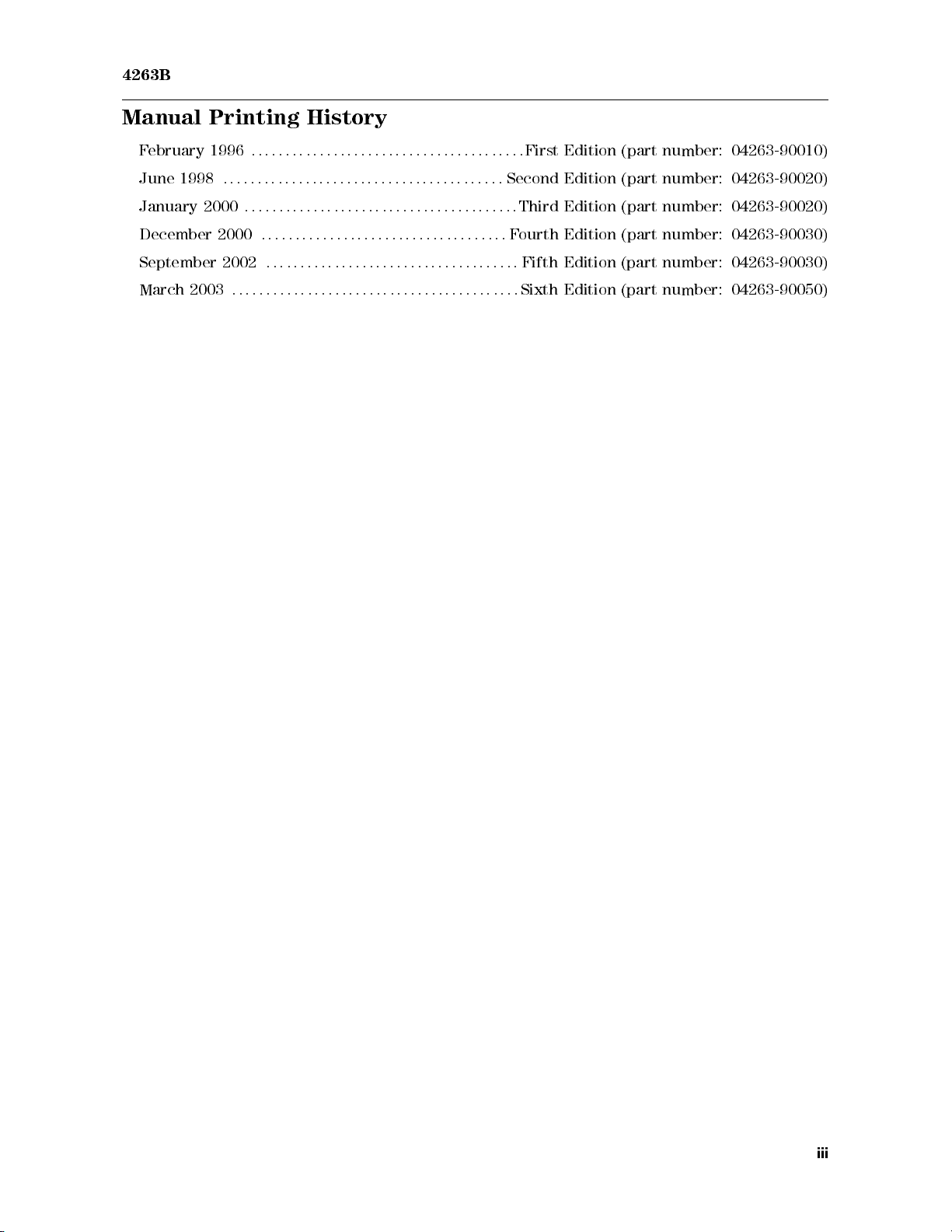
4263B
Manual Printing
F
ebruary
June
January
December
September
March
1998
2003
1996
:
2000
2000
2002
:
:
:
:
:
:
:
:
:
:
::
::
::
:
:
:
:
:
::
:
:
:
:
:
:
:
:
:
:
:
:
:
::
::
History
:
:
::
::
::
::
::
::
::
::
::
::
:
:
:
:
:
::
::
:
:
:
:
:
::
::
::
:
:
:
::
::
:
::
::
:
::
:
::
:
::
:
::
:
::
::
::
:
:
:
:
:
:
:
:
:
:
:
::
::
::
:
First
Edition (part
:
:
:
:
:
:
:
:
:
::
::
::
::
::
:
::
:
Second
:
:
:
:
:
:
:
:
:
:
:
::
::
::
::
::
:
:
:
:
:
:
:
:
:
:
:
:
:
:
:
:
:
::
Fourth
:
:
:
:
:
:
:
:
:
:
:
:
:
:
:
:
:
::
:
:
:
:
:
:
:
:
:
:
::
::
::
::
:
:
:
:
Edition (part
Third Edition
Edition (part
Fifth
Edition (part
Sixth
Edition
number: 04263-90010)
number:
(part number:
04263-90020)
04263-90020)
number: 04263-90030)
number: 04263-90030)
(part
number:
04263-90050)
iii
Page 12
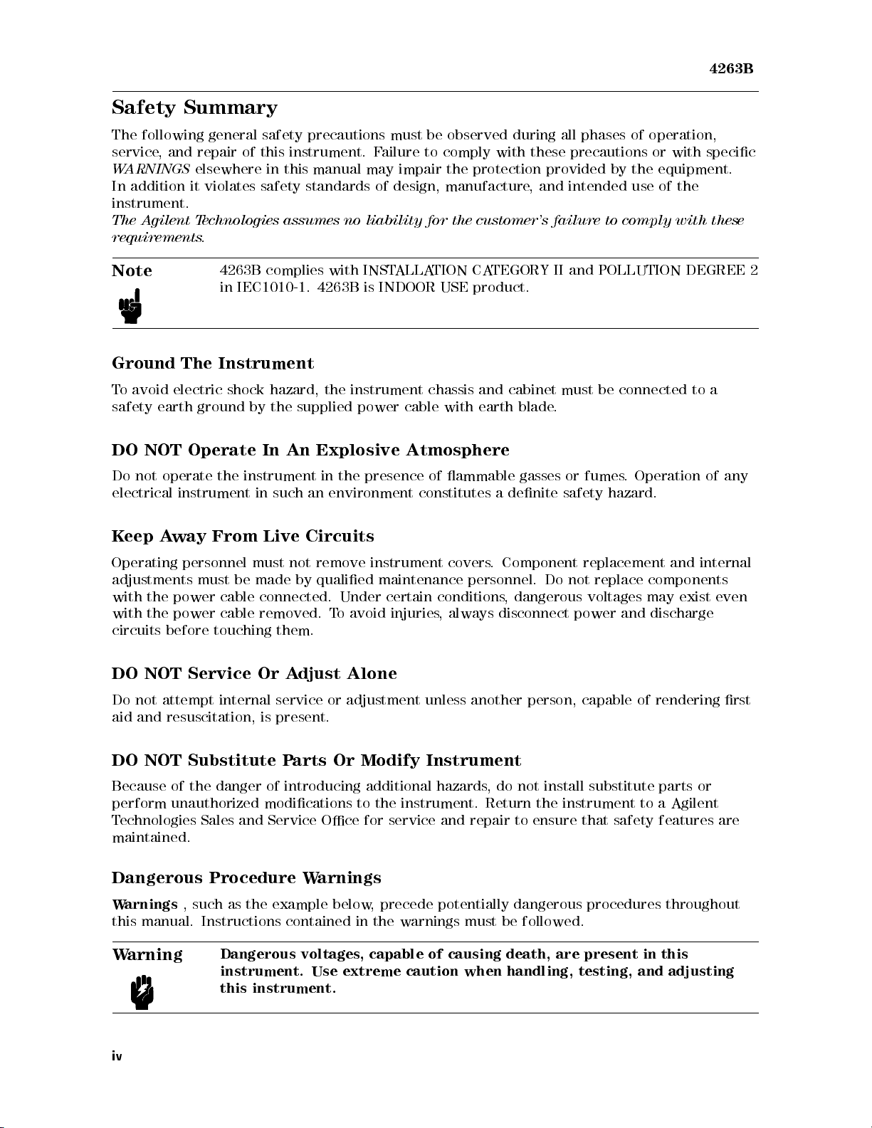
Safety Summary
The
following
service
W
ARNINGS
In
addition
,
and
elsewhere
it
general
repair
violates
safety
of this
in
safety standards
instrument.
The
A
gilent
requirements
T
echnologies assumes
.
precautions must
instrument. F
this manual
no liability
be observed
ailure to
may impair
of design,
for the
during all
comply with
the protection
manufacture,
customer's failure
phases of
these precautions
provided by
and intended
the equipment.
use of
to
comply
operation,
or with
the
with
4263B
specic
these
Note
Ground
T
o
avoid
safety
DO
Do
not operate
electrical
Keep
The
electric
earth
NOT
instrument in
A
way
Operating
adjustments
with
the
power cable
with
the
power
circuits
DO
before
NOT
4263B
in
complies
IEC1010-1.
Instrument
shock
ground
Operate
the
hazard,
by
the
In
instrument
such
From
Live
personnel must
must
be made
connected.
cable
removed.
touching
Service
Or
with
INST
ALLA
4263B
supplied
An
Explosive Atmosphere
in
an
is
INDOOR
the
instrument
power
the
presence
environment
cable
Circuits
not
remove
by
qualied
Under
T
o
avoid
instrument
maintenance
certain
injuries
them.
A
djust
Alone
TION
CA
USE
product.
chassis
of
and
with
earth
ammable
constitutes
covers
personnel.
conditions
,
always
TEGORY
cabinet
blade
gasses
a
denite
.
Component
,
dangerous
disconnect
II
.
Do
and
must
or
safety
not
power
POLLUTION
be
connected
fumes
.
Operation
hazard.
replacement
replace
voltages
components
may
and
discharge
DEGREE
to
and
internal
exist
a
of
even
2
any
Do
not
attempt
aid
and
resuscitation,
DO
NOT
Because of the danger
perform unauthorized modications to
Technologies Sales and Service
internal
is
Substitute
service
or
adjustment
unless
another
present.
P
arts
Or
Modify
Instrument
of introducing additional hazards
the instrument. Return the instrument to a Agilent
Oce for service and repair to ensure that safety features are
person,
, do not install substitute parts or
maintained.
Dangerous Procedure W
Warnings
, such as the example below
arnings
, precede potentially dangerous procedures throughout
this manual. Instructions contained in the warnings must be followed.
Warning
Dangerous voltages, capable of causing death, are present in this
instrument. Use extreme caution when handling, testing, and adjusting
this instrument.
iv
capable
of
rendering
rst
Page 13
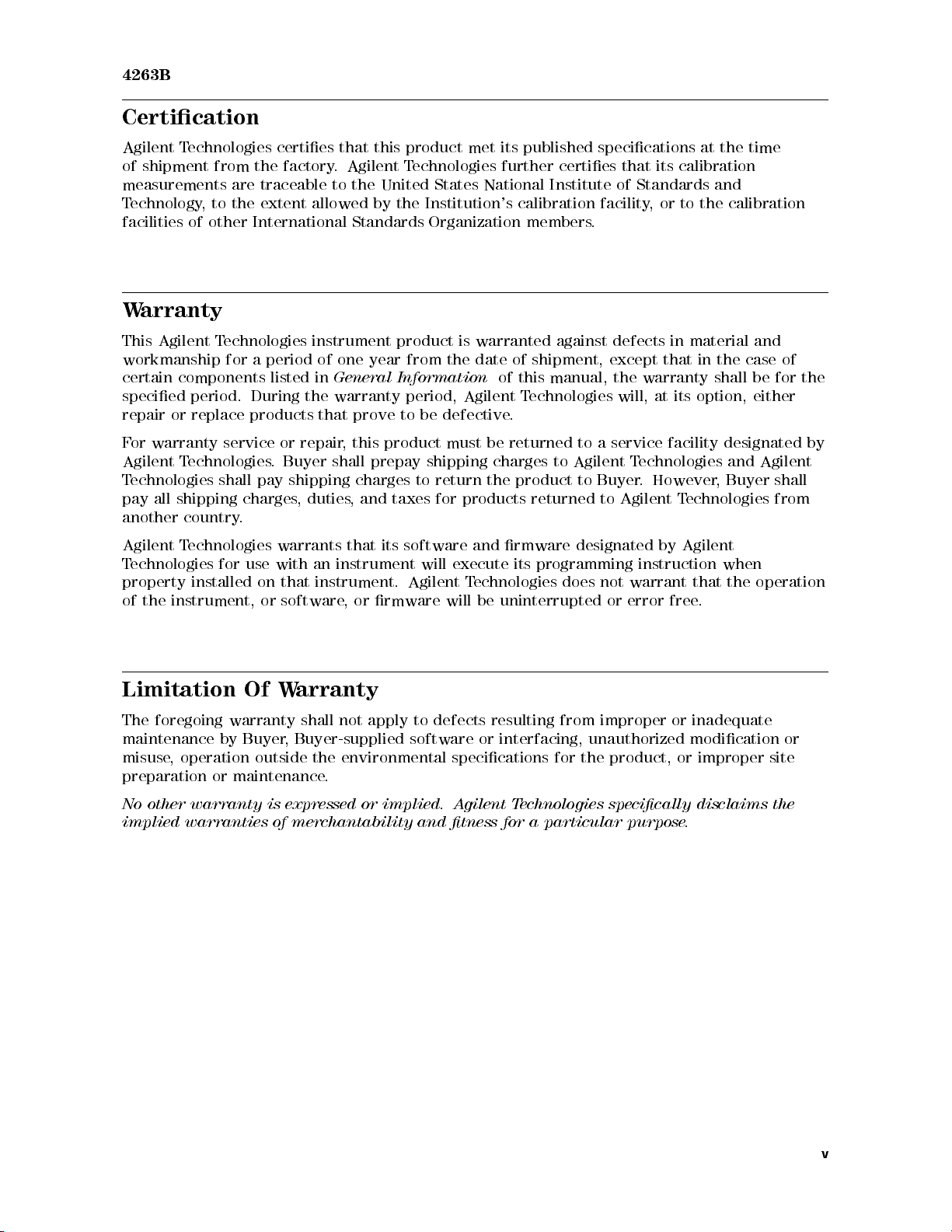
4263B
Certication
Agilent
of
T
echnologies
shipment
from
measurements
T
echnology
facilities
W
arranty
This
of
Agilent
,
to
other
workmanship
certain
specied
repair
F
or
Agilent
T
echnologies
pay
another
Agilent
T
echnologies
property
of
components
or
warranty
Technologies
all
shipping
country
T
echnologies
the
instrument,
period.
replace
installed
certies
the
are
traceable
the extent
International
T
echnologies
for
a
period
listed
During
products
service
. Buyer
shall
pay
charges
.
warrants
for
use
with
on
or
factory.
to
allowed by
instrument
of
one
in
General
the warranty
that
or
repair
shall
shipping
,
duties
an
instrument
that
instrument.
software
that this
Agilent T
the United
product met
echnologies further
States National
the Institution's
Standards Organization
year
product
from the
is
warranted against
date of
Information
period, Agilent
prove to
,
this
prepay
charges
,
and
that
,
or
be defective
product
shipping
to
taxes
its
software
will
Agilent
rmware
must
return
for
products
execute
T
will
and
echnologies
be
its published
certies that
Institute of
calibration facility
members.
shipment, except
of
this manual,
Technologies
.
be returned
charges
the
to
product
Agilent
returned
rmware
its
programming
does
uninterrupted
specications at
its calibration
Standards and
,or
defects in
the
warranty
will,
at
to
a
service
T
echnologies
to
Buyer
.
However
to
Agilent
designated
instruction
not
warrant
or
error
to the
material and
that
in
its
option,
facility
T
echnologies
by
Agilent
that
free.
the time
calibration
the
case
of
shall
be
for
either
designated
and
Agilent
,
Buyer
shall
from
when
the operation
the
by
Limitation
The
foregoing
maintenance
misuse
,
preparation
No
other
implied
by
operation
or
warranty
warranties
Of
W
arranty
warranty
Buyer
shall
,
Buyer-supplied
outside
maintenance
is
expressed
of
merchantability
not
apply
the
environmental
.
or
to
software
implied.
and
defects
resulting
or
specications
A
gilent
tness
from
interfacing,
for
the
T
echnologies
for a
particular purpose
improper
or
unauthorized
product,
specically
inadequate
modication
or
improper
disclaims
.
or
site
the
v
Page 14
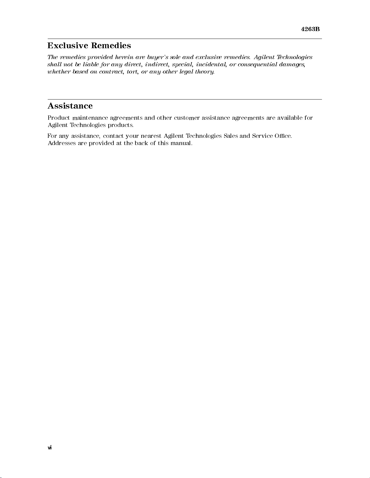
Exclusive Remedies
The
remedies
shall
not
whether
be
liable
based
provided
for any
on
contract,
herein
direct, indirect,
Assistance
are buyer's
tort, or
sole and
special, incidental,
any other
exclusive remedies
legal theory
or consequential
.
.A
gilent T
4263B
echnologies
damages,
Product
Agilent
F
or
any
A
ddresses
maintenance
T
echnologies
assistance
are
,
provided
agreements
products
contact
at
the
and
.
your
nearest Agilent
back
other
of this
customer
Technologies
manual.
assistance
Sales and
agreements
Service
are
available for
Oce
.
vi
Page 15
4263B
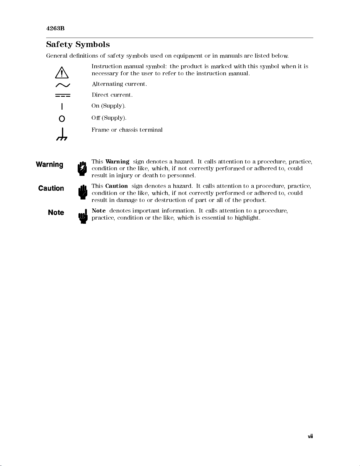
Safety Symbols
General
denitions
Instruction
necessary
Alternating
Direct
On
O
Frame
This
condition
result
This
condition
result
Note
practice
of
safety
current.
(Supply).
(Supply).
or
W
arning
in injury
Caution
in
damage
denotes
,
condition
symbols used
manual
for
the
user
current.
chassis
terminal
sign
or
the
like
or
death
sign
or
the
like
to
important
on equipment
symbol:
to refer
denotes
,
which,
to
denotes a
,
which,
or
destruction
information.
or
the
like
the
product is
to the
a
hazard.
if
not
correctly
personnel.
hazard.
if
not
correctly
of
,
which
or in
manuals are
marked with
instruction manual.
It
calls attention
performed or
It
calls
attention
performed
part
or
all
of
the
It
calls
attention
is
essential
to
highlight.
listed below
this symbol
to a
procedure
adhered
to
a
procedure
or
adhered
product.
to
a
procedure
.
when it
,
practice
to
,
could
,
practice
to
,
could
,
is
,
,
vii
Page 16
Herstellerbescheinigung
GERX
SCHEMISSION
LpA
<
70
dB
am
Arbeitsplatz
normaler
nach
DIN
Betrieb
45635
T
.19
Manufacturer's Declaration
A
COUSTIC
LpA
<
NOISE
70 dB
EMISSION
operator position
normal
per
operation
ISO
7779
4263B
viii
Page 17
4263B
Contents of
Chapter
Provides
4263B
Chapter
Shows
wish
Chapter
Describes
about
Chapter
Shows how
about the
Chapter
1
the
product overview
should
2
how
to
to
learn
3
all
functions
the
functions
4
to remotely
procedures for
5
read
operate
about
this Manual
and basic
this
chapter
the
operations
of this
of the
operate
rst.
4263B
from
using
instrument. Please
front and
the
remotely operating
measurement procedure
its
front
panel.
the
front
panel
keys
refer to
rear panel
4263B
.
Please
the
keys
4263B
and
refer
Please
.
this
terminals
to
this
via
the
. First
refer
to
chapter
.
chapter
GPIB
time users
this
when
when
.
chapter
you
you
of the
when
wish
wish
to
you
learn
to
learn
Contains
this
trigger
Chapter
Provides
Chapter
Provides
complete information
chapter
when
system,
you
and
6
a
measurement example
7
information for
on
wish
to
learn
data
transmission
eective operations
remotely
about
format.
using the
Chapter 8
Provides
specications
,
reference
data,
and
Chapter 9
Describes how to verify the specications
operating
the
4263B
.
other
.
GPIB
.
general
the
4263B
's
commands
information.
via
,
status
the
GPIB
.
Please
reporting
refer
to
mechanism,
ix
Page 18
4263B
Appendix
Contains
information
printed.
Appendix
Contains
handler
information which
interface,
Appendix
Contains
the
(No-Contact).
A
B
please read
C
summary
on
using
of
operations
the
4263B
is required
this
appendix
,
when
s
for
which
using
and
the
were
the
set
4263B
manufactured
handler
the
detects
interface
handler
O
before this
interface
VLD
(Overload),
.
Before
input/output
manual was
using
the
signal.
or N.C.
x
Page 19
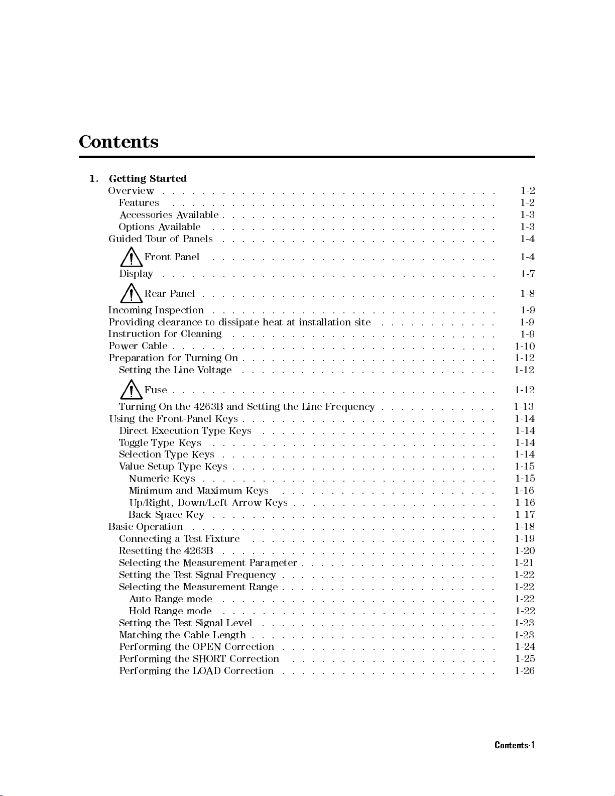
Contents
1.
Getting
Overview
F
A
Options
Guided
Display
Incoming
Providing
Instruction
P
ower
Preparation
Setting
Turning
Using
Direct
T
Selection
V
Basic
Connecting
Resetting the 4263B
Selecting the Measurement P
Setting the T
Selecting the Measurement Range . . . . . . . . . . . . . .
Setting the T
Matching the Cable Length . . . . . . . . . . . . . . . . .
Performing the OPEN Correction ...................... 1-24
Performing the SHORT Correction ...... ...... ...... ... 1-25
Performing the LOAD Correction ... ..... ...... ...... .. 1-26
Started
eatures
ccessories
T
our
Front
Rear
Cable
Fuse
the
Execution
oggle
alue
Setup
Numeric
Minimum
Up/Right,
Back
Operation
Auto Range mode
Hold Range mode
.
.
.
.
.
.
.
.
.
.
.
.
.
.
.
A
vailable
A
vailable
of
P
anels
P
anel
.
.
.
P
anel
Inspection
clearance
for
Cleaning
.
.
.
for
Turning
the
Line
.
..
On
the
Front-P
Type
Space
anel
Keys
Type
Keys
Type
Keys
and
Down/Left
Key
.
a
T
est Fixture
est Signal Frequency . .
est Signal Level
.
.
.
.
.
.
.
.
.
.
.
.
.
.
.
.
.
.
..
.
.
.
to
dissipate
.
.
.
.
.
On
V
oltage
.
.
.
.
4263B
Maximum
and
Keys
Type
Keys
.
.
.
.
.
Keys
.
.
.
.
.
Arrow
.
.
.
.
..
..
...
..............
.... ...... ......
.
.
.
.
.
.
.
.
..
..
..
..
.
.
.
.
.
.
.
.
.
.
.
.
.
.
.
.
..
..
..
..
.
.
.
.
.
.
.
.
.
.
.
.
.
.
.
.
.
.
.
..
..
..
..
.
.
.
.
.
.
.
.
.
.
.
.
.
.
.
.
.
.
..
..
..
.
.
.
.
.
.
.
.
.
.
.
.
.
.
.
.
..
..
..
.
.
.
.
.
.
.
.
.
.
.
.
.
.
.
.
.
.
.
.
..
..
..
.
.
.
.
.
.
.
.
.
.
.
.
.
.
.
.
.
.
..
..
.
.
.
.
.
.
.
.
.
.
.
.
.
.
.
.
.
.
.
.
.
.
.
.
.
.
.
.
.
.
.
.
.
.
.
.
.
.
.
.
.
..
..
..
.
.
.
.
.
.
.
heat
at
installation
.
.
.
.
.
.
..
..
..
..
.
.
.
.
.
.
.
.
.
.
.
..
..
.
.
.
.
.
.
.
..
.
.
.
.
.
.
.
.
.
Setting
.
.
.
.
.
.
.
.
.
.
Keys
.
.
..
.
..... ..... ...... ...... ...
the
Line
.
.
.
.
.
.
.
.
.
.
.
.
.
.
.
.
.
.
.
.
.
.
.
.
.
.
.
.
.
.
.
.
..
..
.
.
.
.
.
.
..
.
.
.
.
.
Keys
.
.
.
.
.
.
.
.
.
.
..
..
..
..
.
.
.
.
.
.
.
arameter . .
..............
..................
....................
site
.
.
.
.
.
.
.
.
.
.
.
.
.
.
.
.
.
.
Frequency
.
.
.
.
.
.
.
.
.
.
.
.
..
..
..
..
..
..
.
.
.
.
.
.
.
.
..
..
..
.
.
.
.
.
..
..............
.
.
.
.
.
.
.
.
..
.
.
.
.
.
.
.
.
.
.
.
.
.
.
.
.
.
.
.
.
.
.
.
.
.
.
.
.
.
.
.
.
.
.
.
.
.
.
.
.
.
.
.
.
.
.
.
.
.
.
..
.
.
.
.
.
.
.
.
.
.
.
.
.
.
.
.
.
..
.
.
.
.
.
.
.
.
.
.
.
.
..
..
.
.
..
..
.
.
.
.
.
.
.
.
.
.
.
.
.
.
.
.
.
.
.
.
.
.
.
.
.
.
.
.
.
.
.
.
.
.
.
.
.
..
..
..
.
.
.
.
.
.
..
..
..
..
.
..
.
.
.
.
.
.
.
.
.
.
.
.
.
.
.
.
.
..
.
.
.
.
.
.
.
.
.
.
...... ..
...... ......
..........
........
.
.
.
.
.
.
.
.
.
.
.
.
.
.
..
.
.
..
.
.
.
. 1-10
.
.
.
.
.
.
.
.
.
.
.
.
.
.
.
.
.
.
.
.
.
.
.
.
.
.
..
..
1-2
1-2
1-3
1-3
1-4
1-4
1-7
1-8
1-9
1-9
1-9
1-12
1-12
1-12
1-13
1-14
1-14
1-14
1-14
1-15
1-15
1-16
1-16
1-17
1-18
1-19
1-20
1-21
1-22
1-22
1-22
1-22
1-23
1-23
Contents-1
Page 20
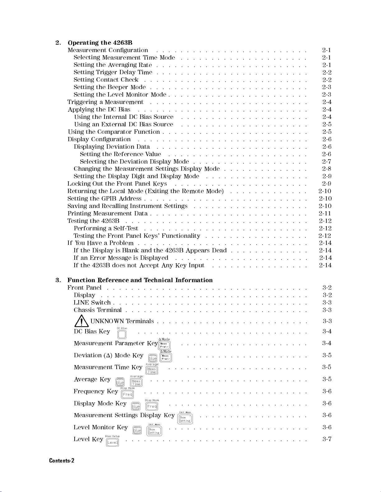
2.
Operating the
Measurement
Selecting
Setting
Setting
Setting
Setting
Setting
Triggering
Applying
Using
Using
Using
Display
Displaying
Setting
Selecting
Changing
Setting
Locking
Returning
Setting
Saving
Printing
T
esting
P
erforming
T
esting
If
Y
ou
If
the
If
an
If
the 4263B
4263B
Conguration .
Measurement Time
the A
veraging
Trigger Delay
Contact Check
the
Beeper
the
Level
a
Measurement
the
DC
Bias
the
Internal
an
External
the
Comparator
Conguration
Deviation
the
Reference
the
Deviation
the
Measurement
the
Display
Out
the
Front
the
Local
the
GPIB
A
and
Recalling
Measurement
the
4263B .
a
Self-T
the
Front
Have
a
Problem
Display
Error
is
Message
does
.
Mode
Rate
.
.
Time
Mode
Monitor
.
DC
DC
Function
.
Data
Digit
P
Mode
ddress
Instrument Settings
Data
..
est
P
anel Keys'
.
Blank
is
not
.
.
.
.
.
.
Mode
.
.
.
.
.
Bias
Source
Bias
Source
.
.
.
.
V
alue
Display
Settings
and
Display
anel
Keys
(Exiting
.
.
.
..
.
.
.
..
.
.
.
.
and
the
Displayed
A
ccept
.
.
.
.
.
.
.
.
.
..
.
.
Functionality
.
4263B
Any
.
.
.
.
.
.
.
.
.
.
.
.
.
.
.
.
.
.
.
.
.
.
.
.
Mode
.
the
..
.
.
.
.
.
.
.
.
.
.
.
.
.
.
.
.
.
.
.
.
.
.
.
.
.
.
.
.
.
.
.
.
.
.
.
.
.
Display
Mode
.
.
Remote
..
.
.
.
.
.
.
.
.
Appears
.
.
Key
.
.
.
.
.
.
.
.
.
.
.
.
.
.
.
.
.
..
..
.
.
.
.
.
.
Input
.
.
.
.
.
.
.
.
.
.
.
.
.
.
.
.
..
.
.
.
..
..
..
.
.
.
.
.
.
Mode
.
.
.
Mode)
..
.
.
.
.
.
.
.
.
.
.
.
.
.
.
.
.
..
.
..
..
..
.
.
.
..
..
.
.
..
..
..
..
..
.
.
.
.
.
.
.
.
.
.
.
.
.
.
.
.
.
.
.
Dead
.
.
.
.
.
..
.
.
..
..
..
..
..
..
..
.
..
..
..
..
..
..
.
.
.
.
.
.
.
..
.
.
.
.
.
.
.
.
.
.
.
.
.
.
.
.
.
.
.
.
..
.
..
..
..
..
..
..
..
..
..
..
..
.
.
..
..
..
.
.
.
.
.
..
.
.
.
.
.
.
.
.
.
.
.
.
.
..
.
.
.
.
.
.
..
..
..
..
..
..
..
..
.
.
..
.
.
.
.
.
.
.
.
.
..
..
.
..
.
.
..
.
.
.
.
.
.
.
.
.
.
.
.
.
.
.
.
.
.
.
..
..
..
..
.
..
.
.
.
.
.
.
.
..
..
.
..
.
.
.
.
.
.
.
.
.
.
.
.
..
..
..
.
.
.
.
.
.
.
..
.
.
.
.
.
.
.
.
.
.
.
.
.
.
.
.
.
.
.
.
.
.
..
.
.
.
.
.
.
.
.
.
.
.
..
..
..
..
..
.
.
.
.
.
.
.
.
.
.
.
.
.
.
.
.
.
.
.
.
.
.
.
.
.
.
.
.
.
.
.
.
.
.
.
.
..
.
.
.
.
.
.
.
.
.
..
.
.
..
..
.
..
.
.
.
.
.
.
.
.
.
.
.
.
.
.
.
.
.
.
.
.
.
.
.
.
.
.
.
.
.
.
.
.
.
.
.
.
.
.
.
..
.
.
.
.
.
.
.
.
..
. 2-1
. 2-1
.
2-1
.
2-2
.
2-2
.
2-3
.
2-3
.
2-4
.
2-4
.
2-4
.
2-5
.
2-5
.
2-6
.
2-6
.
2-6
.
2-7
.
2-8
.
2-9
.
2-9
.
2-10
.
2-10
.
2-10
. 2-11
.
2-12
2-12
.
2-12
.
2-14
.
2-14
.
2-14
2-14
3.
Function
Front
Display
LINE
Chassis
DC
Measurement P
Deviation (1) Mode Key
Measurement Time Key ..... ..... ....
Average Key ...... .....
Frequency Key .... ...... ...... ..
Display Mode Key ....................... 3-6
Measurement Settings Display Key ...... ...... ...... 3-6
Level Monitor Key ...... ...... ...... ..... 3-6
Level Key
Reference
P
anel
.
.
.
Switch
T
erminal
UNKNOWN
Bias
Key
and
T
echnical
.
.
.
.
.
.
.
.
.
.
.
.
.
.
.
.
.
.
.
.
.
.
.
.
.
.
.
.
.
.
T
erminals
.
arameter Key
...... ...... ...... ..... ...... . 3-7
.
.
.
..
Information
.
.
..
.
.
.
.
.
.
.
.
.
.
.
.
.
.
.
.
.
.
.
...... .....
..
..
..
.
.
.
..
..
..
.
.
.
..
..
..
.
.
.
..
..
..
.
.
.
.
.
.
.
.
.
.
.
.
.
.
.
..
..... ...
...............
.
.
.
.
.
.
.
.
.
.
.
.
.
.
.
.
.
.
.
.
.
.
.
.
.
.
.
.
.
.
.
.
.
..
.
.
.
.
.
.
.
.
..
..
..
..
.
.
.
.
.
.
.
.
.
.
.
.
.
..........
............
...... ...
...... ...
.
.
.
.
.
.
3-2
3-2
3-3
3-3
3-3
3-4
3-4
3-5
3-5
3-5
3-6
Contents-2
Page 21
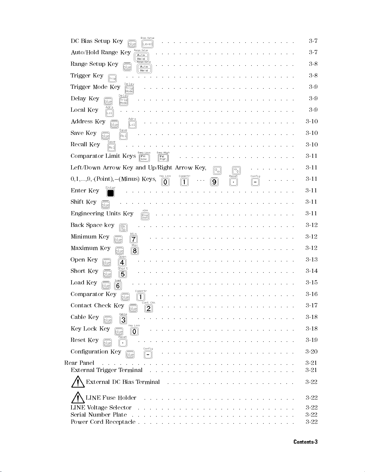
DC
Bias Setup
Key
.
..
..
.
.
.
.
.
.
.
.
.
.
.
.
.
..
..
. 3-7
Auto/Hold
Range
Trigger
Trigger
Delay
Local Key
A
Save Key
Recall
Comparator
Left/Down
0,1,..,9,
Enter
Shift
Engineering
Back
Setup
Key
Mode
Key
ddress Key
Key
1
(P
Key .
Key
Space
Range
Key
Key
Limit
Arrow
oint),
0
Units Key
key
Key
.
.
..
..
.
.
Keys
Key
(Minus)
.
.
..
.
.
..
.
and
.
..
.
.
..
.
Keys
.
.
..
.
.
.
.
.
.
.
.
.
..
.
..
.
.
.
.
Up/Right
,
.
.
.
.
.
.
.
.
.
.
.
..
.
.
.
..
.
..
.
.
.
.
.
.
.
.
..
.
.
.
.
.
.
.
.
..
.
..
..
.
.
.
..
.
.
.
.
.
.
.
.
.
Arrow
.
..
.
.
.
.
.
.
.
.
.
.
.
.
.
..
..
..
.
.
.
.
.
.
.
.
.
.
Key
.
..
.
.
.
.
.
.
.
.
..
..
..
.
.
.
.
.
.
.
..
.
.
.
.
.
.
.
..
..
..
..
..
. 3-7
.
.
.
..
..
..
..
..
..
..
..
..
.
.
.
.
.
.
.
..
.
.
.
.
.
.
.
.
.
.
.
.
.
.
.
.
.
.
.
.
.
.
.
.
.
.
.
.
.
.
.
.
.
.
..
..
.
.
.
.
.
.
.
.
.
.
.
.
.
..
.
.
.
.
.
.
.
.
.
..
..
..
.
.
.
.
.
.
..
..
..
.
.
.
.
.
.
.
.
.
.
.
.
..
..
.
.
.
,
..
.
.
.
.
.
.
.
.
.
.
.
.
.
.
.
.
.
.
.
.
.
.
.
.
.
..
.
.
.
.
.
.
.
.
.
.
.
.
.
.
.
.
.
.
.
..
..
.
.
.
.
.
.
.
.
.
.
.
.
3-8
.
3-8
.
3-9
.
3-9
. 3-9
3-10
3-10
.
3-10
. 3-11
.
3-11
.
3-11
.
3-11
3-11
.
3-11
.
3-12
Minimum
Maximum
Open
Short
Load
Comparator
Contact
Cable
Key Lock Key
Reset Key .. ...... ....
Conguration Key
Rear P
External Trigger T
LINE Voltage Selector ........................... 3-22
Serial Number Plate .. ...... ...... ...... ...... .. 3-22
Power Cord Receptacle . . . . . . . . . . . . . . . . . . . . . . . . . . . 3-22
Key
Key
Key
Key
Key
Key
Check
Key
anel ............
External DC Bias Terminal .. ...... ...... ...... .. 3-22
LINE Fuse Holder .... ...... ...... ..... ..... 3-22
Key
erminal ............
.
.
.
.
.
.
.
.
.
.
.
.
.
.
.
..
.
.
.
.
.
.
.
.
.
.
.
.
.
.
..
.
.
.
.
.
.
.
.
.
.
.
.
.
.
.
.
.
.
.
.
.
..
..
.
.
.
.
.
.
.
.
.
.
.
.
.
.
.
.
.
.
.
.
.
.
.
.
.
.
.
.
.
.
.
.
.
.
.
.
.
.
..
..
.
.
.
.
.
.
.
.
.
.
.
.
.
.
.
.
.
.
.
.
.
..
..
..
.
.
.
.
.
.
.
.
.
.
.
.
..
..
..
.
.
.
.
.
.
.
.
.
.
.
.
.
.
.
.
..
..
..
..
.
.
.
.
.
.
.
.
.
.
.
..
..
..
.
.
.
.
.
.
.
.
.
.
.
..
..
..
..
. 3-18
......
...... ...
..... ..... ...... ...
...... ...... ...
..............
...... ...... ...... ...
.............
3-12
3-12
3-13
3-14
3-15
3-16
3-17
3-18
3-19
3-20
3-21
3-21
Contents-3
Page 22
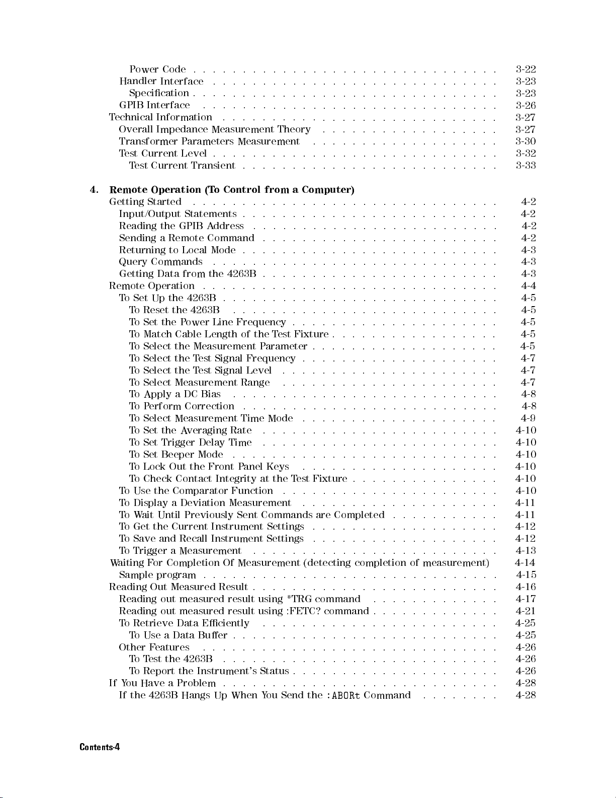
P
ower Code
Handler
Specication
GPIB
T
echnical Information
Overall
Transformer
T
est
T
4.
Remote
Getting
Input/Output
Reading
Sending
Returning
Query
Getting
Remote
T
o
T
T
T
T
T
T
T
T
T
T
T
T
T
T
T
T
o
T
o
T
o
T
o
T
o
To Trigger a Measurement
Waiting F
Sample program . . . . . . . . . .
Reading Out Measured Result . . . . . . . . . . . . . . . . . .
Reading out measured result using *TRG command
Reading out measured result using :FETC? command . . . . . . . . . . . . .
To Retrieve Data Eciently
To Use a Data Buer . . . . . . . . . . . . . . . . . . .
Other Features .... ...... ...... ..... ...... ... 4-26
ToTest the 4263B ............................ 4-26
To Report the Instrument's Status . . . . . . . . . . . . . . . . . . . . . 4-26
If You Have a Problem . . . . . . . . . . . . . . . . . . . . . . . . . . . . 4-28
If the 4263B Hangs Up When You Send the
Interface .
Interface .
Impedance Measurement
Current
est
Current
Operation
Started
the
a
Commands
Data
Operation
Set
Up
o
Reset
o
Set
the
o
Match
o
Select
o
Select
o
Select
o
Select
o
Apply
o
P
erform
o
Select
oSet
the
oSet
Trigger
o
Set
Beeper
o
Lock
o
Check
Use
the
Display
W
ait
Until
Get
the
Save
and
or Completion Of Measurement (detecting completion of measurement)
..
.
.
.
.
.
..
.
.
.
.
.
.
.
.
P
arameters
Level
GPIB
Remote
to
Local
from
the
the
P
Cable Length
the Measurement
the T
the
Measurement
a
Measurement
A
Out
Contact
Comparator
a
Deviation
Current
Recall
.
.
.
Transient
(T
o
Control
.
.
.
.
.
Statements
A
ddress
Command
Mode
.
.
.
the
4263B
.
.
.
.
4263B
4263B
ower
DC
Correction
veraging
the
Previously
.
.
.
Line
est Signal
T
est Signal
Bias
Delay
Mode
.
Rate
Time
.
Front
Integrity
Function
Measurement
Instrument
Instrument Settings
.
.
.
.
.
.
.
.
.
.
..
..
..
.
.
.
.
.
.
.
.
.
..
..
..
..
.
.
.
.
.
.
.
.
..
..
..
..
.
.
.
.
.
.
.
.
..
..
..
..
.
.
.
.
.
.
.
.
.
..
..
..
..
Theory
Measurement
.
.
.
.
.
.
.
.
.
.
from
.
.
.
..
.
.
.
.
.
.
.
.
.
.
.
.
.
.
.
.
.
.
.
.
..
.
.
.
.
.
.
.
.
.
.
.
.
.
.
.
.
..
Frequency
of the
Range
Time
P
Sent
T
est
Parameter
Frequency
Level
.
.
.
anel
.
..
.
.
.
.
.
.
.
.
Mode
.
.
.
.
.
.
.
.
.
.
Keys
at
the
T
.
Commands
Settings .
.....
...................
.
.
.
.
.
.
.
.
.
.
.
.
.
.
.
.
.
.
.
..
..
..
..
.
.
.
.
.
.
..
..
..
a
Computer)
..
..
..
.
.
.
.
.
.
.
.
..
..
..
..
.
.
.
..
..
..
.
.
.
.
.
.
..
..
..
.
.
.
..
..
..
.
.
..
..
.
.
.
.
.
.
.
.
.
..
..
.
.
.
.
.
.
.
.
.
..
.
.
.
.
.
.
.
.
..
.
.
.
.
.
.
..
..
.
.
.
.
.
.
.
.
..
..
..
..
.
.
Fixture
.
.
.
.
.
.
est
.
.
.
.
.
.
.
.
.
.
.
.
.
.
.
.
.
.
.
.
.
.
.
.
.
.
.
.
.
.
.
.
.
.
.
.
.
.
.
.
.
.
.
.
.
.
.
.
.
.
.
.
.
.
.
.
.
.
.
.
.
.
.
.
.
.
.
.
.
.
.
.
.
.
.
.
.
.
.
.
.
.
.
.
.
.
.
.
.
.
.
.
.
.
.
.
.
.
.
.
.
..
..
.
.
.
.
.
.
.
..
..
..
Fixture
.
.
.
.
.
.
are
..
.
.
....................
...... ...... ..... ...
.
.
.
.
.
.
.
Completed
..
.
.
.
:ABORt
.
.
.
.
.
.
..
.
.
.
.
.
..
..
.
.
.
.
...... ...... .
Command ........ 4-28
..
..
..
..
..
..
..
..
..
..
.
.
..
.
..
..
.
.
.
.
..
.
.
.
.
.
.
.
.
.
.
.
.
.
.
.
.
.
.
.
.
.
.
.
.
.
.
.
.
.
.
.
.
.
.
.
.
.
.
.
.
.
.
.
.
.
.
.
.
.
.
.
.
.
.
.
.
.
.
.
.
.
.
.
.
.
.
.
..
.
.
.
.
.
..
.
.
.
.
.
.
.
..
.
.
.
.
.
.
.
.
..
.
.
..
..
..
..
..
..
.
.
.
.
..
.
.
.
.
..
...... .
........
..
.
..
..
.
..
.
..
.
..
..
..
..
.
.
.
.
.
.
.
.
.
.
.
.
.
.
.
.
.
.
.
.
.
.
.
.
.
.
.
.
.
.
.
.
.
.
.
.
.
.
.
.
.
.
.
.
.
.
.
.
.
.
.
.
.
.
.
.
.
.
.
.
.
.
.
.
.
.
.
.
.
.
.
..
..
..
.
.
.
.
.
.
.
..
.
.
.
.
..
..
.
..
..
.
.
.
.
.
.
.
.
.....
.
.
.
.
.
.
.
.
.
.
.
.
.
.
.
.
.
.
.
.
.
.
.
.
..
.
.
.
.
.
.
.
.
.
.
.
.
.
.
.
.
.
.
.
.
..
.
.
.
.
.
.
.
.
.
.
3-22
.
3-23
.
3-23
.
3-26
.
3-27
3-27
.
3-30
.
3-32
.
3-33
.
4-2
.
4-2
.
4-2
.
4-2
.
4-3
.
4-3
.
4-3
.
4-4
.
4-5
.
4-5
.
4-5
.
4-5
.
4-5
.
4-7
.
4-7
.
4-7
.
4-8
.
4-8
4-9
.
4-10
.
4-10
.
4-10
.
4-10
.
4-10
.
4-10
.
4-11
. 4-11
.
4-12
.
4-12
4-13
4-14
4-15
4-16
4-17
4-21
4-25
4-25
Contents-4
Page 23
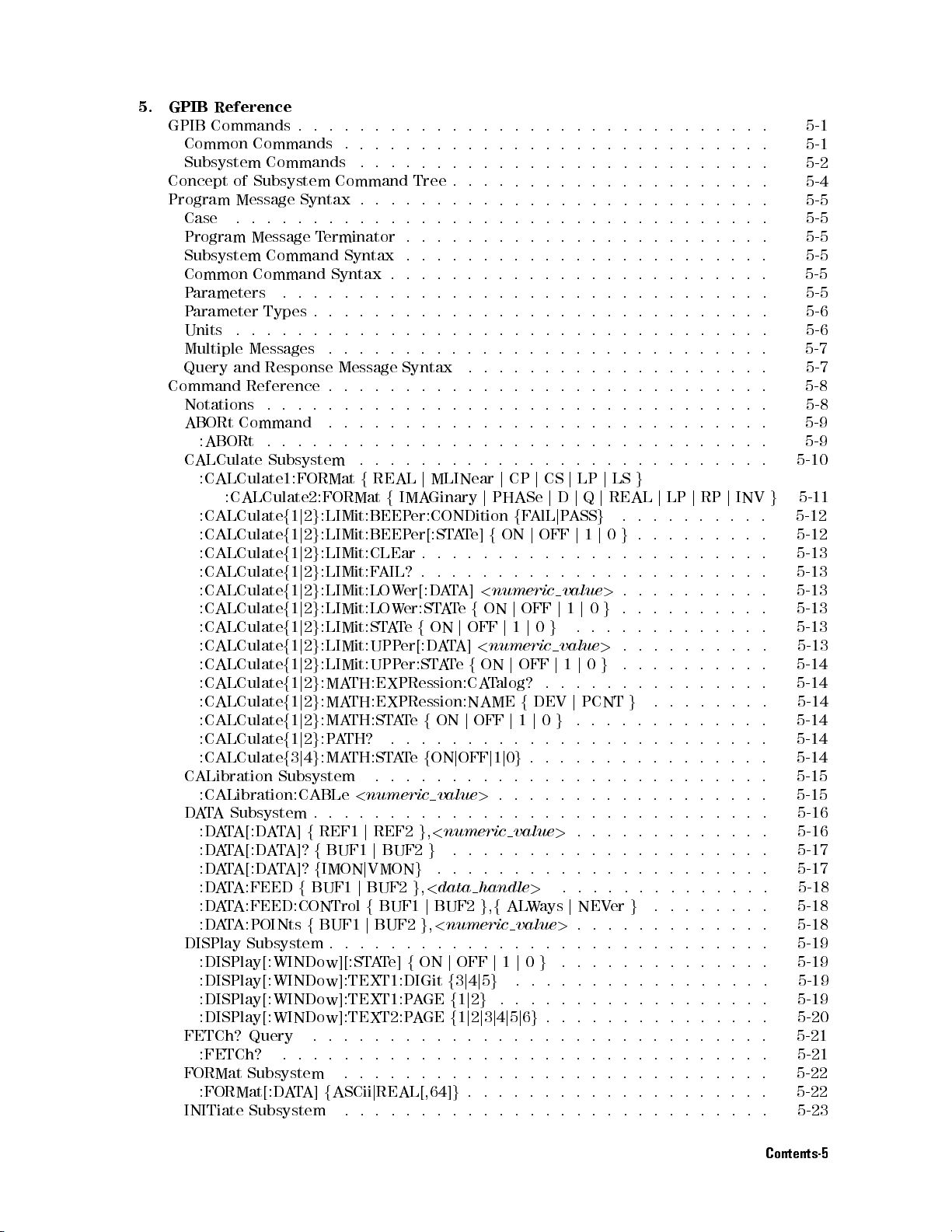
5.
GPIB Reference
GPIB
Commands .
Common
Subsystem
Concept
Program
Case
Program
Subsystem
Common
P
arameters
P
arameter
Units
Multiple
Query
Command
Notations
ABORt
:ABORt
CALCulate
:CALCulate1:FORMat
:CALCulate
:CALCulate
:CALCulate
:CALCulate
:CALCulate
:CALCulate
:CALCulate
:CALCulate
:CALCulate
:CALCulate
:CALCulate
:CALCulate
:CALCulate
:CALCulate
CALibration
:CALibration:CABLe
D
A
T
:D
:DATA[:DATA]?fBUF1
:DATA[:DATA]?fIMONjVMON
:DATA:FEEDfBUF1jBUF2g,<data
:DATA:FEED:CONTrolfBUF1jBUF2g,fALW
:DATA:POINtsfBUF1jBUF2g,<numeric
DISPlay Subsystem . . . . . . . . . . . . . . . . . . . . .
:DISPlay[:WINDow][:STATe]fONjOFFj1j0g...... .....
:DISPlay[:WINDow]:TEXT1:DIGitf3j4j5g...... ..
:DISPlay[:WINDow]:TEXT1:PAGEf1j2g...... ...... ...... 5-19
:DISPlay[:WINDow]:TEXT2:PAGEf1j2j3j4j5j6g...... ..... .... 5-20
FETCh? Query .............................. 5-21
:FETCh? ...... ...... ...... ...... ...... .. 5-21
FORMat Subsystem ... ...... ..... ...... ...... .. 5-22
:FORMat[:DATA]fASCiijREAL[,64]g.................... 5-22
INITiate Subsystem ............................ 5-23
Commands .
Commands .
of Subsystem
Message Syntax
.
.
Message
Command
Command
Types
.
.
.
Messages
and
Response
Reference
.
Command
.
:CALCulate2:FORMat
A
Subsystem
A
T
A[:D
A
.
.
.
.
.
.
.
T
erminator
Syntax
.
.
.
.
.
.
.
.
.
.
.
.
.
.
.
.
.
.
.
.
.
Subsystem
f
1
j
2
g
:LIMit:BEEP
f
1
j
2
g
:LIMit:BEEP
f
1
j
2
g
:LIMit:CLEar
f
1
j
2
g
:LIMit:F
f
1
j
2
g
:LIMit:LOW
f
1
j
2
g
:LIMit:LOW
f
1
j
2
g
:LIMit:ST
f
1
j
2
g
:LIMit:UPP
f
1
j
2
g
:LIMit:UPP
f
1
j
2
g
:MA
f
1
j
2
g
:MA
f
1
j
2
g
:MA
f
1
j
2
g
:P
f
3
j
4
g
:MA
Subsystem
.
..
TA]
f
REF1
.
.
.
.
.
.
.
.
.
.
.
.
.
.
.
.
.
.
.
.
.
.
.
.
Command
.
.
.
Syntax
.
.
.
.
.
.
.
.
Message
.
.
.
.
.
.
.
.
.
f
TH:EXPRession:CA
TH:EXPRession:NAME
TH:ST
A
TH?
TH:ST
<
numeric
..
j
Tree
.
.
.
.
.
.
.
.
.
.
.
.
.
..
..
.
.
.
.
.
.
.
.
.
.
.
.
.
.
.
.
.
.
.
.
.
.
..
.
.
.
..
..
..
..
..
..
.
.
.
.
.
.
.
Syntax
.
.
.
.
.
.
.
.
.
.
.
.
.
.
.
REAL
f
IMA
er:CONDition
er[:ST
AIL?
.
er[:D
er:ST
A
T
e
f
er[:D
er:ST
A
T
e
.
.
A
T
e
.
.
.
..
REF2
g
j
BUF2g.....................
g
.
.
.
.
.
.
..
..
.
.
..
.
.
.
.
.
.
.
.
j
MLINear
Ginary
A
T
e]
.
.
.
.
.
.
.
A
T
A]
A
T
e
f
ON
j
OFF
A
T
A]
A
T
e
f
f
ON
j
.
.
.
.
f
ON
j
OFF
.
.
.
.
value
..
..
,
<
numeric
..... ..... ...... ......
..
..
..
..
..
..
..
.
.
.
..
..
..
..
..
.
.
.
.
..
..
..
..
..
.
.
.
.
.
.
.
..
..
..
.
.
.
..
..
..
..
..
..
..
.
.
.
.
.
.
.
.
.
.
.
.
.
..
..
..
..
.
.
.
.
.
.
..
..
..
..
.
.
.
.
.
..
..
..
..
..
..
..
.
.
.
.
.
.
..
..
.
.
.
.
.
.
.
.
.
.
.
.
.
.
.
.
.
.
.
.
.
..
..
..
.
.
.
.
.
.
.
.
.
.
.
.
.
..
..
..
.
..
..
..
.
.
.
.
.
.
.
..
.
.
.
.
.
.
.
.
.
.
..
.
.
.
.
.
.
.
.
.
.
.
..
.
.
.
.
.
.
.
.
.
.
.
.
.
.
.
.
.
..
.
.
.
.
.
j
CP
j
CS
j
LP
j
LS
g
j
PHASe
f
.
.
.
.
<
numeric
ON
<
numeric
ON
T
alog?
OFF
.
..
j
1
.
.
>
.
..
handle
j
D
j
Q
j
REAL
f
F
AlL
j
P
ASS
g
ON
j
OFF
j
1
j
0
.
.
.
.
.
.
.
.
.
.
.
.
.
.
value
>
j
OFF
j
1
j
0
g
j
1
j
0
g
.
.
.
value
>
j
OFF
j
1
j
0
g
.
.
.
.
.
f
DEV
j
PCNT
j
1
j
0
g
..
.
..
..
.
.
j
0
g
..
.
.
.
.
.
.
.
.
.
..
.
.
.
.
.
.
.
.
.
.
.
.
.
.
value
>
.
.
.
>
...... ....
aysjNEVerg........
value>...... ...... .
j
LP
.
.
.
.
g
.
.
.
.
.
.
.
.
.
.
.
.
.
.
..
.
.
.
..
.
.
..
.
.
.
.
.
.
.
.
.
.
.
.
g
.
.
.
.
.
.
.
.
.
.
.
.
.
.
..
..
.
.
.
.
.
.
.
.
..
.
.
...... ..
...... ...
.
..
..
..
..
.
.
.
.
.
.
.
.
.
.
.
.
.
.
.
.
.
.
.
.
.
.
.
.
.
.
.
j
RP
.
.
.
.
.
.
.
.
.
.
.
.
.
.
..
.
.
.
.
.
.
.
.
.
.
..
.
.
.
.
.
.
.
..
..
..
.
.
.
.
.
.
.
.
.
.
.
.
.
.
.
.
.
.
.
.
.
.
..
.
.
.
.
.
.
..
..
.
....
.
.
.
..
..
.
.
.
.
.
.
.
.
.
.
.
.
.
.
.
.
.
.
.
.
.
.
.
.
.
.
.
.
.
j
INV
.
.
.
.
.
..
.
.
.
.
.
.
.
.
.
.
.
.
.
.
.
.
.
.
.
.
.
.
.
..
..
.
.
...
.
5-1
.
5-1
.
5-2
5-4
.
5-5
.
5-5
.
5-5
.
5-5
.
5-5
.
5-5
.
5-6
. 5-6
.
5-7
.
5-7
.
5-8
.
5-8
.
5-9
.
5-9
.
5-10
g
5-11
.
5-12
. 5-12
5-13
. 5-13
.
5-13
.
5-13
.
5-13
.
5-13
.
5-14
. 5-14
.
5-14
.
5-14
.
5-14
.
5-14
.
5-15
5-15
5-16
.
5-16
5-17
5-17
5-18
5-18
5-18
5-19
5-19
5-19
Contents-5
Page 24
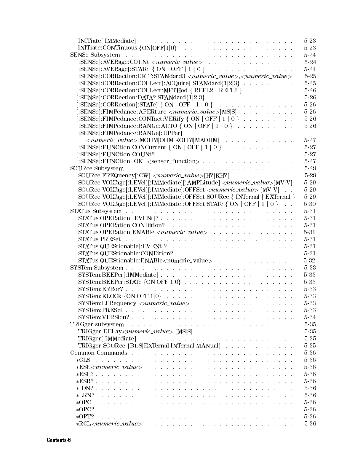
:INITiate[:IMMediate]
:lNITiate:CONTinuous
SENSe
SOURce
ST
SYST
TRIGger subsystem
CommonCommands ....................
Subsystem .
[:SENSe]:A
[:SENSe]:A
[:SENSe]:CORRection:CKIT:ST
[:SENSe]:CORRection:COLLect[:A
[:SENSe]:CORRection:COLLect:METHod
[:SENSe]:CORRection:D
[:SENSe]:CORRection[:ST
[:SENSe]:FIMP
[:SENSe]:FIMP
[:SENSe]:FIMP
[:SENSe]:FIMP
<
[:SENSe]:FUNCtion:CONCurrent
[:SENSe]:FUNCtion:COUNt?
[:SENSe]:FUNCtion[:ON]
:SOURce:FREQuency[:CW]
:SOURce:V
:SOURce:V
:SOURce:V
:SOURce:V
A
Tus
:ST
A
:ST
A
:ST
A
:ST
A
:ST
A
:ST
ATus:QUEStionable:CONDition?
:ST
ATus:QUEStionable:ENABle
em Subsystem
:SYST
:SYST
:SYST
:SYST
:SYST
:SYST
:SYST
:TRIGger:DELay<numeric
:TRIGger[:IMMediate] ...........
:TRIGger:SOURcefBUSjEXTernaljINTernaljMANualg.
3
CLS .....................
3
ESE<numeric
3
ESE?...... ...... ...... .....
3
ESR?.................................. 5-36
3
IDN? . . . . . . . . . . . . . . . . . . . . . . . . . . . . . . . . . . 5-36
3
LRN? . ...... ..... ...... ...... ...... ... 5-36
3
OPC ..... ...... ..... ...... ...... ...... 5-36
3
OPC? . . .
3
OPT?.................................. 5-36
3
RCL<numeric value>......................... 5-36
VERage:COUNt
VERage[:STA
edance:APERture
edance:CONT
edance:RANGe:A
edance:RANGe[:UPP
numeric
Subsystem
Subsystem .
Tus:OPERation[:EVENt]?
Tus:OPERation:CONDition?
Tus:OPERation:ENABle
Tus:PRESet
Tus:QUEStionable[:EVENt]?
em:BEEP
em:BEEP
em:ERRor?
em:KLOCk
em:LFRequency
em:PRESet
em:VERSion?
value
OL
T
age[:LEV
OL
T
age[:LEV
OL
T
age[:LEVel][:IMMediate]:OFFSet:SOURce
OL
T
age[:LEVel][:IMMediate]:OFFSet:ST
.
.
er[:IMMediate]
er:ST
.
f
.
value>......................
............................... 5-36
..
..
.
.
.
.
f
ON
j
OFF
j
1
j
0
g
.
.
.
.
.
.
.
.
.
.
.
<
numeric
T
e]
f
ON
ANdard3
A
T
A?
ST
ANdard
A
T
e]
f
ON
act:VERify
UTO
>
[MOHM
.
.
..
.
.
.
.
A
T
e
.
.
ON
j
OFF
<
.
.
.
.
...... ..
j
OHM
.
<
sensor
.
.
.
.
<
numeric
el][:IMMediate][:AMPLitude]
el][:IMMediate]:OFFSet
.
.
.
.
.
<
numeric
.
.
.
.
<
.
.
.
.
.
f
ON
j
OFF
.
.
.
.
j
1
j
0
g
numeric
.
..
..
.
..
.
value>[MSjS]......
value
j
OFF
j
CQuire]
f
j
OFF
<
numeric
f
f
ON
er]
j
KOHM
f
ON
j
.
.
.
.
function
.
.
.
.
value
.
.
.
.
.
..
.
.
.
..
.
.
.
.
.
.
.
.
.
numeric
.
.
.
.
.
.
.
.
j
1
j
0
g
.
.
.
.
.
.
.
.
.
value
>
..
..
.
.
.
.
....................
.
.
.
.
.
.
.
..
>
1
j
0
<
numeric
ST
ANdard
f
REFL2
1
j
2
j
3
g
j
1
j
value
ON
j
j
OFF
j
MA
OFF
j
.
.
>
.
.
>
.
.
.
.
.
.
.
.
value
.
.
.
.
.
.
.
.
.
value
.
.
.
.
.
.
..
..
.
.
.
.
..
.
.
..
.
.
.
.
.
.
.
.
.
..
..
..
..
..
..
..
..
..
..
..
..
..
..
..
..
..
.
.
.
.
.
.
.
.
.
.
.
.
.
..
g
..
..
..
..
..
..
..
.
.
.
.
..
..
.
.
[MV
j
.
.
.
.
.
.
.
.
.
.
.
.
.
.
.
..
..
.
.
.
.
.
.
.
.
.
.
.
..
.
.
.
.
..
.
..
..
..
.
.
..
.
.
.
.
>
j
EXT
1
j
..
.
.
.
.
.
.
.
.
.
.
.
.
.
.
value
..
.
.
.
.
.
.
.
.
.
.
.
[MV
j
V]
ernal
0
g
.
.
.
.
.
.
.
.
.
.
.
.
.
.
.
.
.
.
.
.
.
.
.
.
.
.
.
.
.
.
.
.
..
.
.
.
.
.
.
.
..
.
.
...
value
>
,
<
numeric
f
1
j
2
j
3
g
.
.
j
REFL3
.
..
0
g
.
>
[MS
OFF
j
j
1
j
OHM]
1
j
0
g
.
.
.
.
.
.
.
.
.
..
.
[HZ
j
KHZ]
<
<
numeric
AT
e
.
.
.
.
.
.
.
.
.
>
.
.
.
.
.
.
.
.
.
.
.
>
.
.
.
.
.
.
.
..
..
..
..
..
.
.
.
..
.
.
.
.
...... ...... ...
.............
g
.
..
..
..
..
..
..
j
S]
.
.
1
j
0
g
..
0
g
..
..
.
.
..
..
.
.
..
..
..
..
..
.
.
.
.
..
.
.
.
.
.
.
.
.
.
numeric
f
f
ON
.
.
.
.
.
.
.
.
.
.
.
.
.
.
.
.
.
.
..
.
.
..
..
.
.
.
.
..
...........
...... .....
...........
value
value
>
INT
ernal
j
OFF
.
.
.
.
.
.
.
.
.
.
.
.
.
.
..
.
.
.
.
.
.
.
.
.
.
.
..
..
..
.
.
.
.
.
.
.
.
.
.
.
.
.
.
.
.
........
. 5-23
.
.
.
. 5-24
.
>
..
.
.
.
.
.
.
.
.
.
.
.
.
.
.
.
.
.
.
.
.
.
.
.
.
j
V]
.
.
g
.
.
.
.
.
.
.
.
.
.
.
.
.
.
.
.
.
.
.
.
.
.
.
.
.
.
.
. 5-33
.
.
.
.
5-23
5-24
5-24
5-25
5-25
5-26
5-26
5-26
5-26
5-26
5-26
5-27
5-27
5-27
5-27
5-29
5-29
5-29
5-29
5-29
5-30
5-31
5-31
5-31
5-31
5-31
5-31
5-31
5-32
5-33
5-33
5-33
5-33
5-33
5-33
5-34
5-35
5-35
5-35
5-35
5-36
5-36
5-36
5-36
Contents-6
Page 25
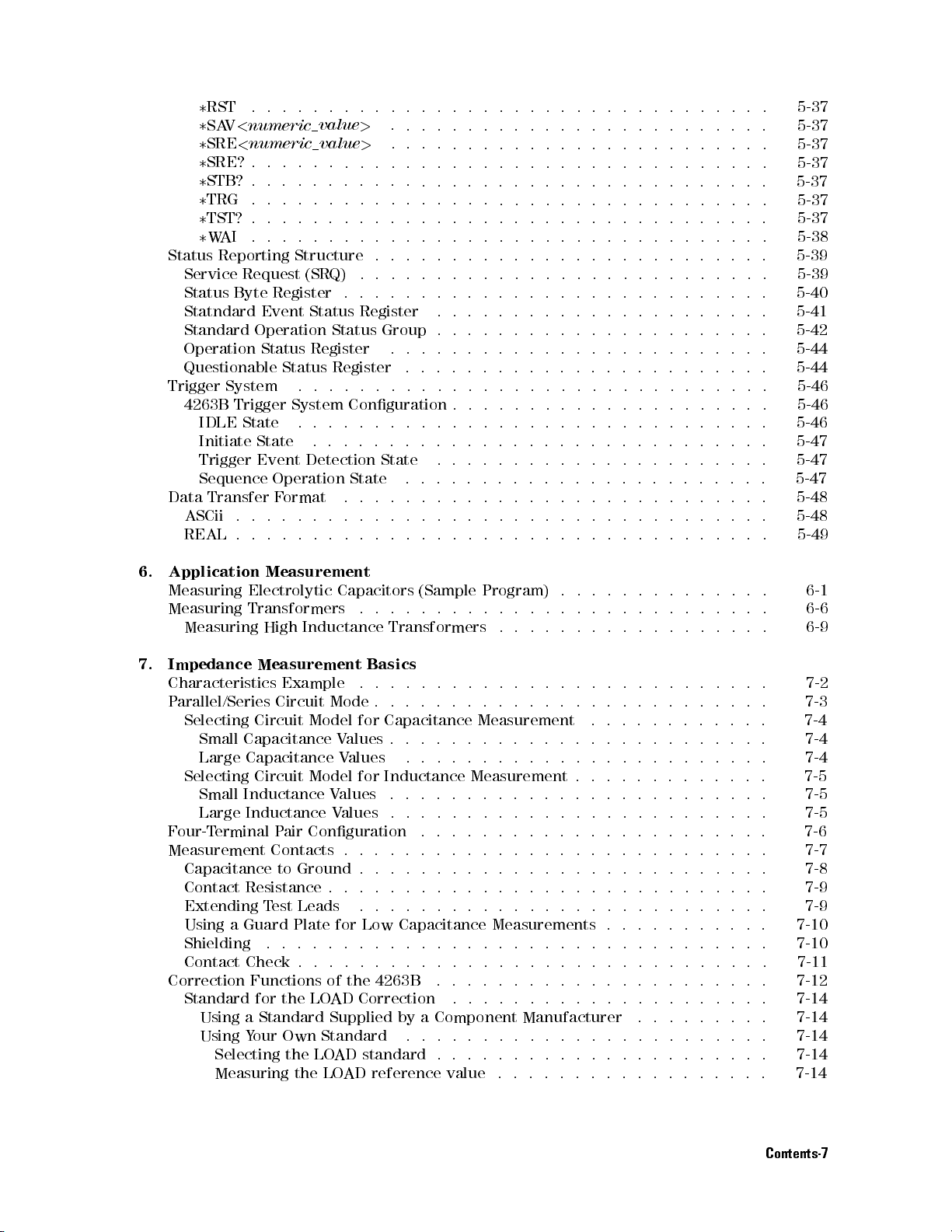
3
RST .
3
SAV
3
SRE
3
SRE? .
3
STB? .
3
TRG .
3
TST?
3
W
AI
Status
Trigger
Data
Reporting
Service
Status
Statndard
Standard
Operation
Questionable
4263B
ASCii
REAL
Byte
System
Trigger
IDLE
Initiate
Trigger
Sequence
Transfer
..
<
numeric
<
numeric
.
.
.
.
.
.
.
Request
Register
Event
Operation
Status
State
State
Event
Operation
.
.
..
.
.
..
.
.
.
.
.
.
.
.
.
.
.
Structure
(SRQ)
Status
Register
Status
.
System
.
Detection
F
ormat
..
..
.
.
.
.
value
>
value
>
.
.
.
.
.
.
.
.
.
.
.
.
.
.
.
.
.
.
.
.
.
.
.
Register
Status
Register
.
.
.
.
Conguration
.
.
.
.
.
.
.
.
State
.
.
.
.
.
.
.
.
.
.
.
.
.
.
.
.
.
.
.
.
.
.
.
.
.
.
.
.
Group
.
.
.
.
.
.
.
State
.
.
.
.
.
.
.
.
.
.
.
.
.
.
.
.
.
.
.
.
.
.
.
.
.
.
.
.
.
.
.
.
.
..
.
..
.
..
.
..
..
.
.
.
.
.
.
.
.
.
.
.
.
.
.
..
.
.
.
.
.
..
.
.
.
.
.
.
.
.
.
.
..
..
..
..
..
.
.
.
.
.
.
.
.
.
.
.
.
.
.
..
.
.
..
.
.
.
.
.
.
..
.
.
.
.
.
..
.
.
.
.
..
..
..
..
..
.
.
.
.
.
.
.
.
.
.
.
.
.
.
..
.
.
.
.
.
.
.
.
.
..
..
.
.
.
.
..
.
.
.
.
..
..
..
..
..
.
.
.
..
..
.
..
.
..
.
..
.
.
..
.
.
.
.
..
.
.
..
..
.
.
.
.
..
.
.
.
.
..
..
..
.
.
.
..
..
..
..
..
..
..
.
.
.
.
.
.
.
.
.
.
..
.
.
.
.
.
.
..
..
..
..
..
..
.
.
.
.
..
..
..
..
..
..
..
.
.
..
.
.
.
.
.
.
.
.
.
.
.
.
.
..
..
..
..
..
..
.
.
.
.
..
..
..
..
..
.
..
.
.
..
.
.
.
.
.
..
.
.
.
.
.
.
.
.
..
..
..
.
.
.
.
.
.
.
..
.
.
.
.
.
.
.
.
.
.
.
..
.
.
.
.
.
.
.
.
.
.
..
.
..
.
..
..
.
.
.
.
.
.
.
.
.
.
.
.
.
.
.
.
.
.
.
.
.
.
.
.
.
.
.
.
.
.
.
.
.
.
.
.
.
.
..
..
.
.
..
..
.
.
.
.
.
.
.
.
.
.
.
.
.
.
.
.
.
.
.
.
.
.
.
.
.
.
.
.
.
.
.
.
.
.
.
.
.
.
.
.
.
.
..
..
.
.
.
.
.
.
.
.
.
.
.
.
.
.
.
.
.
.
.
.
.
.
.
.
.
.
.
.
.
.
.
.
.
.
.
.
.
.
.
.
.
.
.
5-37
. 5-37
. 5-37
.
5-37
.
5-37
.
5-37
.
5-37
.
5-38
.
5-39
.
5-39
.
5-40
.
5-41
.
5-42
.
5-44
.
5-44
.
5-46
.
5-46
.
5-46
.
5-47
.
5-47
.
5-47
.
5-48
.
5-48
.
5-49
6.
Application
Measuring
Measuring
Measuring
7.
Impedance Measurement
Characteristics
P
arallel/Series
Selecting
Small
Large
Selecting
Small
Large
F
our-T
erminal
Measurement Contacts . . . . . . . .
Capacitance to Ground . . . . . . . .
ContactResistance........ ..
Extending T
Using a Guard Plate for Low Capacitance Measurements . . . . . . . . . . .
Shielding . .... ..... ...... ......
ContactCheck......................
Correction Functions of the 4263B
Standard for the LOAD Correction ..................... 7-14
Using a Standard Supplied by a Component Manufacturer .... ..... 7-14
Using Your Own Standard ...... ...... ...... ...... 7-14
Selecting the LOADstandard.... ...... ...... ...... 7-14
Measuring the LOAD reference value .................. 7-14
Measurement
Electrolytic
Transformers
High
Inductance
Example .
Circuit
Circuit
Capacitance
Capacitance
Circuit
Inductance
Inductance
Model
Model
P
air
Conguration .
est Leads
Capacitors
.
Basics
Mode
for
V
alues
V
alues
for
V
alues
V
alues
...... ..... ...... .
(Sample
.
.
.
.
.
Transformers
.
.
.
.
.
.
.
.
.
.
Capacitance
.
.
.
.
.
.
.
Inductance
.
.
.
.
.
.
..
.
....................
Program)
.
.
.
.
.
.
.
.
.
.
.
.
.
.
.
.
.
Measurement
.
.
.
.
.
.
.
.
.
.
Measurement
..
..
..
..
..
..
.
.
.
.
.
....................
...... ...... ..... ..
...... ..... ...... ..
.
.
.
.
.
.
.
..
.
.
.
.
.
.
.
..
.
.
.
.
..
..
.
.
.
.
.
.
.
.
.
.
.
.
.
.
.
.
..
.
.
.
.
.
.
.
.
.
.
.
.
.
.
.
.
..
.
.
.
.
.
.
.
.
.
.
.
.
.
.
..
..
..
.
.
.
.
..
..
..
.
.
.
.
.
.
.
.
.
.
.
.
.
.
.
.
.
.
.
.
..
.
.
.
.
.
.
.
.
..
.
.
.
.
.
.........
...... .....
...... ...
.
.
.
.
.
..
.
..
.
.
.
.
.
.
.
.
.
.
.
.
.
..
.
.
..
.
.
.
.
..
.
.
.
.
.
.
..
.
6-1
.
6-6
.
6-9
.
7-2
.
7-3
7-4
.
7-4
.
7-4
. 7-5
.
7-5
.
7-5
.
7-6
7-7
7-8
7-9
7-9
7-10
7-10
7-11
7-12
Contents-7
Page 26
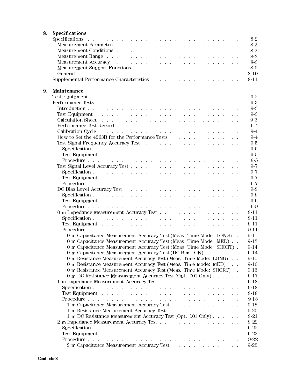
8.
Specications
Specications
Measurement
Measurement
Measurement
Measurement
Measurement
General
Supplemental
9.
Maintenance
T
est
Equipment
P
erformance
Introduction
T
est
Calculation
P
erformance
Calibration
How
T
est
Specication
T
Procedure
T
est
Specication
T
Procedure
DC
Specication
T
Procedure
0
m Impedance
Specication
T
Procedure
1 m Impedance Measurement A
Specication.....................
Test Equipment ....................
Procedure . . . . . . . . . . . . . . . . . . . . . . .
2 m Impedance Measurement Accuracy Test..... ..... ...... . 9-22
Specication............................... 9-22
Test Equipment . ...... ..... ...... ...... ..... 9-22
Procedure . . . . . . . . . . . . . . . . . . . . . . . . . . . . . . . . 9-22
..
.
.
.
.
.
.
.
.
.
.
.
..
..
..
..
..
..
..
.
.
.
.
.
Parameters
Conditions .
Range .
Accuracy
Support
.
.
.
.
.
P
erformance
.
.
T
ests
.
.
.
.
Equipment
to
Set
Signal
est
Equipment
Signal
est
Equipment
Bias
Level
est
Equipment
est
Equipment
0
m
Capacitance
0
m
Capacitance
0
m
Capacitance
0
m
Capacitance
0
m
Resistance
0 m Resistance Measurement A
0 m Resistance Measurement A
0 m DC Resistance Measurement A
1 m Capacitance Measurement A
1 m Resistance Measurement Accuracy Test ............... 9-20
1 m DC Resistance Measurement Accuracy Test (Opt. 001 Only) . . . . . . 9-21
2 m Capacitance Measurement Accuracy Test .............. 9-22
.
Sheet
T
est
Record
Cycle
the
4263B
Frequency
.
.
.
.
..
Level A
ccuracy T
.
.
.
.
.
A
ccuracy
.
.
..
.
Measurement
.
.
.
.
.
.
.
.
.
.
.
.
.
.
.
.
.
Functions
.
.
.
.
.
.
Characteristics
.
.
.
.
.
..
.
.
.
.
.
..
.
.
.
.
.
.
.
.
.
.
.
.
.
.
.
.
.
.
.
.
.
.
.
.
.
.
.
for
the
P
A
ccuracy
.
.
.
.
.
.
.
.
.
.
.
.
..
.
.
.
est
..
..
.
.
.
.
..
.
.
.
..
.
.
.
T
est
.
.
.
.
.
.
.
.
.
.
.
.
.
.
.
.
.
.
.
A
.
.
.
.
.
.
.
.
.
.
.
.
.
.
.
.
.
.
Measurement
Measurement
Measurement
Measurement
Measurement
.
.
.
.
.
.
.
.
.
.
.
.
.
.
.
.
.
.
.
.
.
.
.
.
.
.
..
..
..
..
..
..
.
.
..
..
.
.
..
..
.
.
.
.
..
..
..
..
.
.
..
..
erformance
T
est
.
.
..
..
..
..
..
..
.
.
.
.
.
.
.
.
.
.
.
.
.
.
.
.
.
.
.
.
.
.
.
.
.
.
.
.
.
.
.
.
.
.
.
.
.
.
.
.
.
.
.
.
.
ccuracy
.
.
.
ccuracy T
T
.
.
.
.
.
.
.
.
.
A
ccuracy
A
ccuracy
A
ccuracy
A
ccuracy
A
ccuracy T
ccuracy T
ccuracy T
ccuracy T
ccuracy T
est
.
.
.
est........ ......
.
.
.
..
..
..
..
..
..
.
.
.
.
..
..
..
..
..
.
.
..
..
..
..
..
..
.
.
.
..
..
..
..
..
..
.
.
.
.
.
.
.
..
..
..
..
..
..
.
.
.
.
.
.
.
.
.
.
.
.
.
.
.
.
.
.
.
..
..
..
.
.
.
.
.
.
.
.
.
.
.
.
..
.
.
.
.
.
.
.
.
.
.
.
.
..
.
.
.
.
.
.
.
.
.
.
.
..
.
.
.
.
.
.
.
.
.
.
.
..
..
.
.
.
.
.
.
.
.
.
.
.
.
.
.
.
.
.
.
.
.
.
.
.
.
.
.
.
.
.
.
.
.
.
.
.
T
ests
.
.
.
.
..
.
.
.
.
.
.
.
.
.
.
.
..
.
.
.
.
.
.
.
.
.
.
.
.
.
.
.
.
.
.
.
..
.
.
.
.
.
.
.
.
.
.
.
.
.
.
.
.
.
.
.
.
.
.
.
.
..
.
.
.
.
.
.
.
.
.
.
.
.
.
.
.
.
.
.
.
.
.
.
.
.
.
.
.
.
.
.
.
.
.
.
.
.
.
.
.
.
.
.
.
.
.
.
.
.
.
.
.
.
.
.
.
.
.
.
.
.
.
.
.
.
.
.
..
.
.
.
.
.
.
.
.
.
.
.
.
..
.
.
.
.
.
.
.
.
.
.
.
.
..
.
.
.
.
.
.
.
.
.
.
.
..
..
.
.
.
.
.
.
.
.
.
.
.
.
.
.
.
.
..
..
.
.
.
.
.
.
.
.
..
..
..
..
.
.
.
.
.
.
.
..
..
..
.
.
.
.
.
.
.
T
est
(Meas
.
Time
Mode:
T
est
(Meas
.
Time
Mode:
T
est
(Meas
.
Time
Mode:
Test
(DC Bias:
est
(Meas
.
est (Meas
est (Meas
est ..............
.
. Time
est (Opt. 001 Only)
ON) .
Time
Mode:
Time Mode: MED) . . .
Mode: SHORT)
..........
...... ...
.........
LONG)
MED)
SHORT)
..
LONG)
......
..
..
..
..
.
.
.
..
.
.
.
.
.
.
.
.
.
.
.
.
.
.
.
.
.
.
.
.
.
.
..
.
..
..
.
.
.
..
.
.
.
.
.
.
.
.
.
.
.
.
.
.
.
.
..
...
.
..
.
.
.
.
.
.
.
..
.
.
.
.
.
.
.
.
.
.
.
.
.
.
.
.
.
.
.
.
.
.
.
. 9-7
..
..
.
.
.
.
.
.
.
.
.
.
. 9-11
.
.
.
.
.
.
.
.
.
.
..
.
.
. 9-16
8-10
8-11
9-11
9-11
9-11
9-11
9-13
9-14
9-14
9-15
9-16
9-17
9-18
9-18
9-18
9-18
9-18
8-2
8-2
8-2
8-3
8-3
8-9
9-2
9-3
9-3
9-3
9-3
9-4
9-4
9-4
9-5
9-5
9-5
9-5
9-7
9-7
9-7
9-9
9-9
9-9
9-9
Contents-8
Page 27
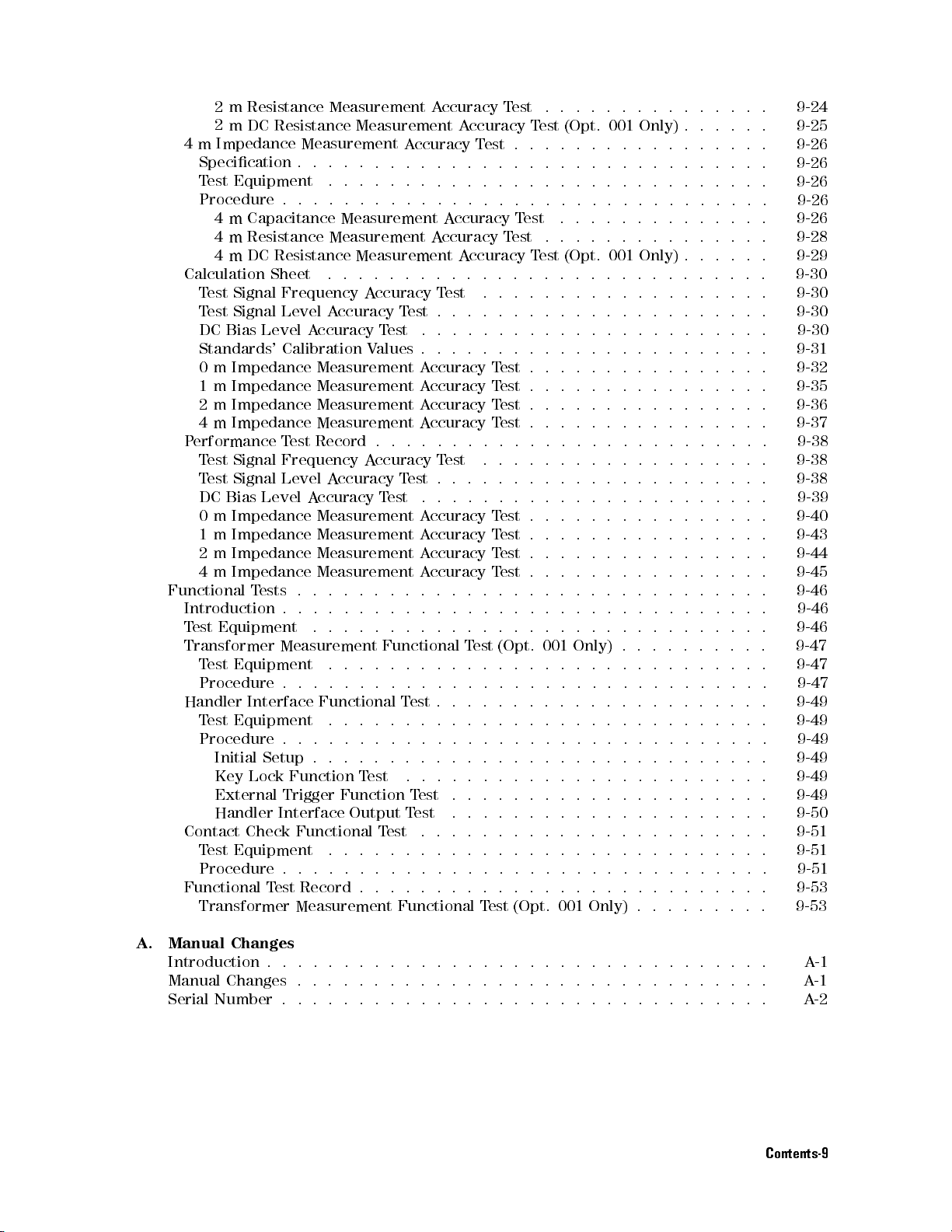
2
m Resistance
2
mDC
4
m Impedance
Specication
T
est Equipment
Procedure
4
m
4
m
4
m
Calculation
T
est
T
est
DC
Bias
Standards'
0
m
1
m
2
m
4
m
P
erformance
T
est
T
est
DC
Bias
0
m
1
m
2
m
4
m
Functional
Introduction
T
est
Equipment
Transformer
T
est Equipment
Procedure
Handler
T
est
Procedure
Initial
Key
External
Handler
Contact
Test Equipment
Procedure....... ...
Functional T
Transformer Measurement Functional T
Resistance
..
Capacitance
Resistance
DC
Resistance
Sheet
Signal
Signal
Impedance
Impedance
Impedance
Impedance
Signal
Signal
Impedance
Impedance
Impedance
Impedance
Equipment
Frequency
Level
Level
Calibration
T
Frequency
Level
Level
T
ests
.
Measurement
..
Interface Functional
.
Setup
Lock
Interface
Check
est Record . . . . . . . .
Measurement A
Measurement
..
.
.
.
.
.
.
.
Measurement
Measurement
.
.
A
ccuracy
A
ccuracy
Measurement
Measurement
Measurement
Measurement
est
Record
A
ccuracy
A
ccuracy
Measurement A
Measurement A
Measurement A
Measurement
.
.
..
.
.
.
.
.
.
.
.
.
.
.
.
.
.
.
.
.
.
.
.
.
Function
Trigger
Function
Output
Functional
.......
Measurement
A
ccuracy
.
.
.
.
.
.
.
.
.
.
.
.
Measurement
.
.
.
.
A
ccuracy
T
est
T
est
V
alues
.
.
.
A
ccuracy
T
est
T
est
.
.
.
.
.
.
.
.
.
.
.
.
Functional
.
.
.
.
.
.
.
.
T
est
.
.
.
.
.
.
.
.
.
.
.
.
T
est
.
T
T
est
T
est
ccuracy
A
.
.
.
.
.
.
.
.
.
A
ccuracy
A
ccuracy
A
.
.
.
T
est
.
.
.
.
.
.
.
.
A
ccuracy
A
ccuracy
A
ccuracy
A
ccuracy
.
.
.
T
est
.
..
.
.
..
ccuracy T
ccuracy T
ccuracy T
A
ccuracy T
.
.
.
.
.
.
.
.
.
.
.
.
.
.
.
.
.
.
.
.
.
.
.
.
.
.
.
.
.
est
.
.
..
.
...... ...... ...... ....
...... ...... ...... ....
T
est
.
.
.
.
.
.
.
.
.
.
..
ccuracy
T
est
.
.
.
.
.
..
ccuracy
.
.
.
..
..
.
.
.
.
.
..
..
.
.
.
.
.
.
T
est
.
.
.
.
.
.
.
.
.
.
.
.
.
.
.
.
..
.
.
.... ...... ...... ...
T
est
(Opt.
001
Only)
.
.
.
.
.
.
.
..
..
..
..
..
..
..
..
..
..
..
..
..
..
..
..
..
..
..
..
..
..
..
T
est
.
.
.
.
.
.
..
..
T
est
.
.
.
.
.
.
..
..
T
est
(Opt.
001
Only)
.
.
..
..
..
..
.
.
.
.
.
.
.
.
.
..
..
..
..
..
..
..
.
.
.
.
.
.
.
..
..
..
.
.
.
.
.
.
.
.
.
.
..
..
..
.
.
.
.
T
est
.
.
.
.
..
..
..
.
T
est
.
.
.
.
..
..
..
.
T
est
.
.
.
.
..
..
..
.
T
est
.
.
..
..
.
.
.
.
.
.
.
..
.
.
.
.
.
.
.
.
.
.
.
.
.
.
.
.
..
.
.
.
.
..
.
.
.
.
.
.
.
.
.
.
..
..
.
.
.
.
.
.
.
.
est
.
.
.
.
.
.
.
.
.
.
.
est
.
.
.
.
.
.
.
.
.
.
.
est
.
.
.
.
.
.
.
.
.
.
.
est
.
.
.
.
.
.
.
.
.
.
.
.
.
.
.
.
.
.
.
.
.
.
.
.
.
.
.
.
.
.
.
.
..
.
.
.
.
.
.
.
.
.
.
.
.
..
.
.
(Opt.
001
Only)
.
.
.
.
.
.
.
.
.
.
.
.
.
.
.
..
..
..
.
..
..
.
.
..
..
.
.
.
.
.
.
.
.
.
.
..
..
..
.
.
.
.
.
est (Opt. 001 Only) . . . . .
.
.
.
.
.
.
..
..
..
..
.
.
..
.
.
.
.
.
.
.
.
.
.
.
..
.
..
..
.
..
.
.
.
.
.
..
..
.
.
.
.
.
.
.
.
..
..
.
.
.
.
..
..
.
.
.
.
.
.
.
.
..
..
.
.
.
.
.
..
..
.
.
.
.
..
..
.
..
.
.
.
.
.
.
.
.
.
.
.
.
.
.
.
.
.
.
.
.
.
.
.
.
.
.
.
.
.
.
.
.
.
.
.
..
.
.
.
.
.
.
.
.
.
.
.
.
.
.
.
.
.
.
.
..
.
.
.
.
....
..
..
..
.
.
.
.
.
.
..
..
..
.
.
.
.
.
.
.
.
.
.
.
.
.
.
.
.
.
.
.
.
.
.
.
.
.
.
.
.
.
.
.
.
.
.
.
.
.
.
.
.
.
.
.
.
.
..
.
.
.
.
.
.
.
.
.
.
.
.
.
. 9-24
9-25
. 9-26
.
9-26
.
9-26
.
9-26
9-26
.
9-28
9-29
.
9-30
.
9-30
.
9-30
.
9-30
.
9-31
.
9-32
.
9-35
.
9-36
.
9-37
.
9-38
.
9-38
.
9-38
.
9-39
.
9-40
.
9-43
.
9-44
.
9-45
.
9-46
.
9-46
.
9-46
.
9-47
.
9-47
.
9-47
. 9-49
.
9-49
.
9-49
.
9-49
.
9-49
.
9-49
.
9-50
.
9-51
9-51
9-51
9-53
9-53
A. Manual Changes
Introduction . . . . . . . . . . . . . . . . . . . . . . .
Manual Changes . . . . . . . . . . . . . . . . . . . . . . .
Serial Number . . . . . . . . . . . . . . . . . . . . . . . . . . . . . . . . A-2
...... ....
........
A-1
A-1
Contents-9
Page 28
B
. Handler
Interface Installation
Introduction
Electrical
Output
Input
Handler
T
ools
Procedure
C.
Overload/No-Contact
Characteristics .
Signals .
Signals .
Interface Board
and
F
asteners
.
Messages
Instrument
GPIB
Errors
Errors
Index
..
.
.
.
.
.
.
.
.
.
.
.
.
.
.
.
.
.
.
.
.
.
.
.
.
.
.
.
.
.
.
.
.
.
.
.
.
.
.
Setup
.
.
.
.
.
.
.
.
.
.
.
Operations
.
.
.
.
.
.
.
.
.
.
.
.
.
.
.
.
.
.
.
.
.
.
.
.
..
.
.
.
.
.
.
.
..
..
..
..
.
.
.
..
.
..
.
.
..
..
..
..
..
.
.
..
..
.
.
..
..
..
.
..
.
..
..
..
.
.
..
..
..
.
.
..
..
..
..
..
..
.
.
.
.
.
..
..
..
..
..
.
.
.
.
.
.
.
.
..
..
..
..
..
.
.
.
.
.
.
.
.
..
..
..
..
..
.
.
.
.
.
.
.
.
.
.
..
.
.
..
.
.
.
.
.
.
.
.
.
.
.
..
.
.
.
.
.
.
..
..
.
.
.
.
.
.
.
.
.
Messages-2
.
.
.
Messages-3
.
B-1
.
B-1
.
B-1
.
B-4
B-5
.
B-5
.
B-5
.
.
Contents-10
Page 29
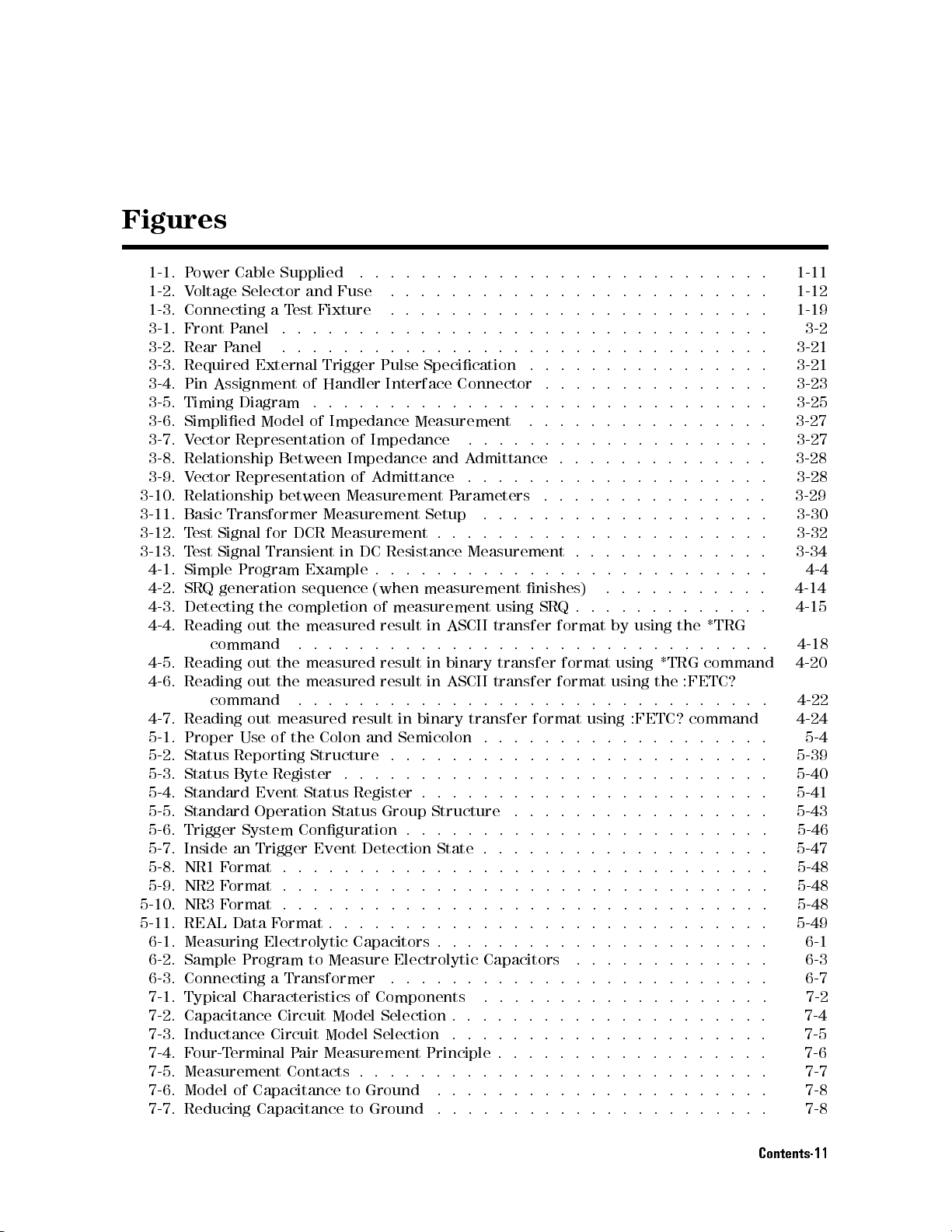
Figures
1-1. P
ower
Cable
Supplied
1-2. V
oltage
1-3. Connecting
3-1. Front
3-2. Rear
3-3.
Required
3-4.
Pin
3-5.
Timing
3-6.
Simplied
3-7.
V
ector
3-8.
Relationship
3-9.
V
ector
3-10. Relationship
3-11.
Basic
3-12.
T
est
3-13.
T
est
4-1.
Simple
4-2.
SRQ
4-3.
Detecting
4-4.
Reading
4-5.
Reading
4-6.
Reading
4-7.
Reading
5-1.
Proper
5-2.
Status Reporting
5-3.
Status Byte
5-4.
Standard Event
5-5.
Standard Operation
5-6.
Trigger
5-7. Inside an Trigger Event Detection State . . . . . . . . . . . . . .
5-8. NR1 F
5-9. NR2 F
5-10. NR3 F
5-11. REAL Data F
6-1. Measuring Electrolytic Capacitors . . . . .
6-2. Sample Program to Measure Electrolytic Capacitors
6-3. Connecting a Transformer
7-1. Typical Characteristics of Components .......... ...... ... 7-2
7-2. Capacitance Circuit Model Selection . . . . . . . . . . . . . . . . . . . . . 7-4
7-3. Inductance Circuit Model Selection ..................... 7-5
7-4. Four-Terminal Pair Measurement Principle . . . . . . . . . . . . . . . . . . 7-6
7-5. Measurement Contacts . . . . . . . . . . . . . . . . . . . . . . . . . . . 7-7
7-6. Model of Capacitance to Ground ...... ...... ..... ..... 7-8
7-7. Reducing Capacitance to Ground .... ...... ...... ...... 7-8
Selector
a
P
anel
.
P
anel
Assignment
Transformer
Signal
Signal
generation
command
command
ormat . .
ormat . . .
ormat . . . .
.
External
Diagram
Model
Representation
Between
Representation
between
for
Transient
Program
the
out
the
out
the
out
the
out
measured
Use
of
Register .
System
ormat...
and
T
est
.
.
.
.
of
.
of
DCR
Example
sequence
completion
measured
.
.
measured
measured
.
.
the
Structure .
Status Register
Conguration
.........................
.
.
.
.
.
.
.
.
.
.
.
.
.
.
..
..
..
..
Fuse
Fixture
.
.
Trigger
Handler
.
Impedance
Measurement
Measurement
in
.
.
Colon
Status Group
...... ..... ...... ...... ..
.
.
.
.
.
.
.
.
.
.
.
.
.
..
..
..
.
.
.
.
.
.
.
.
.
.
.
.
.
..
..
..
.
.
.
.
.
.
.
.
.
.
.
..
..
..
..
.
.
.
.
.
.
.
.
.
.
.
.
.
.
.
.
..
..
..
.
.
.
Pulse
Specication
Interface
.
.
.
.
.
of
Impedance
Impedance
of
A
dmittance
Measurement
DC
Resistance
.
.
.
(when
of
measurement
result
.
.
.
.
.
result
result
.
.
.
.
.
result
in
and
Semicolon
..
..
..
.
.........................
.........................
...... ...... ....
Connector
.
.
.
.
Measurement
.
and
A
dmittance
.
P
arameters
Setup
.
.
.
Measurement
.
.
.
.
measurement
in
ASCII
.
.
.
.
in
binary
in
ASCII
..
..
binary
.
..
.
transfer format
.
.
.
.
.
.
..
Structure .
.
.
.
.
.
.
.
.
.
.
.
.
.
.
.
.
.
.
.
.
.
.
.
.
.
..
..
..
.
.
.
.
.
.
.
.
.
.
.
.
.
.
.
.
.
.
.
.
.
.
.
.
.
.
.
.
.
.
.
.
.
.
.
.
.
.
.
.
.
.
.
.
.
.
..
.
.
.
.
.
.
.
.
.
.
.
.
.
.
.
.
.
.
.
.
.
.
.
.
.
.
.
.
.
.
.
.
.
..
.
.
.
.
.
.
.
.
.
.
.
..
.
.
.
.
.
.
.
nishes)
using
SRQ
transfer
.
.
transfer
transfer
.
.
.
..
.
.
.
.
.
.
.
.
format
.
.
..
format using
.
.
.
..
.
.
.
.
.
.
.
.
.
..
..
.
.................
.
.
.
.
.
.
.
.
.
.
.
.
by
using
the
.
.
.
.
.
.
.
format using
.
.
.
.
using :FETC?
..
.
.
.
.
.
.
.
.
.
.
.
.
.
.
..
.
.
.
.
.
.
............
*TRG command
the :FETC?
.
.
.
.
.
.
.
.
.
.
.
.
.
.
.
.
.
.
.
.
.
.
.
.
.
.
.
.
.........
.
.
.
.
.
..
.
.
.
.
..
.
.
.
.
.
.
.
.
.
.
.
.
.
.
.
.
.
..
..
. 3-21
.
..
..
. 3-23
.
.
.
.
.
.
.
.
.
..
. 3-27
.
.
.
.
..
.
.
.
.
.
.
..
..
.
.
.
.
.
.
..
.
.
.
..
. 3-30
..
.
.
.
.
.
.
.
.
.
. 3-34
.
.
.
.
.
.
.
.
.
..
.
.
..
.
.
.
*TRG
.
.
.
.
.
.
.
.
.
.
.
.
command 4-24
.
.
.
.
.
.
.
.
.
..
. 5-39
..
..
..
.
.
.
.
..
.
.
.
.
.
.
.
..
.
.
.
.....
.....
....
...
. 5-49
. 6-3
1-11
1-12
1-19
3-2
3-21
3-25
3-27
3-28
3-28
3-29
3-32
4-4
4-14
4-15
4-18
4-20
4-22
5-4
5-40
5-41
5-43
5-46
5-47
5-48
5-48
5-48
6-1
6-7
Contents-11
Page 30
7-8.
Contact Conguration
7-9.
Measurement Contacts
7-10.
Example of
7-11.
Guard Shield
7-12.
Stray Capacitance
8-1.
Conversion Diagram
8-2.
Maximum
9-1.
T
est
Signal
9-2.
T
est
Signal
9-3.
DC
Bias
Level
9-4.
DC
Bias
Level
9-5.
0
m
Impedance
9-6.
1
m
Impedance
9-7.
2
m
Impedance
9-8.
4
m
Impedance
9-9.
Transformer
9-10.
9-11.
9-12.
A
-1.
B-1.
B-2.
B-3.
B-4.
Handler
Handler
Contact
Serial
Handler
Handler
Handler
A1
Number
Main
Interface
interface
Check
Interface
Interface
Interface
Board .
DUT
Guard
.
.
Causing
Capacitor
Frequency
Level
A
ccuracy
A
ccuracy
A
ccuracy
Measurement
Measurement
Measurement
Measurement
Measurement
Functional
Output
Functional
Plate
Comparison
Control
Input Signal
.
.
.
V
oltage
.
..
..
for
Plate
.
.
.
.
A
ccuracy
T
est
T
est
Order
T
.
.
Output
.
.
.
.
.
.
T
est
Lead
Connection
.
.
.
.
Contact
.
T
est
Setup
Setup
Functional
est
.
.
Check
.
.
.
.
.
.
T
est
Setup
Without
A
ccuracy
A
ccuracy
A
ccuracy
A
ccuracy
T
est
Setup
.
.
Setup
.
.
.
Output
Signals
Diagram .
.
.
.
.
.
.
.
Extension
.
.
..
..
Error
.
.
.
.
.
.
.
.
Setup
.
.
.
.
.
.
.
T
est
T
est
T
est
T
est
T
est
Setup
.
.
.
.
.
..
.
.
.
.
.
.
.
Signals
Diagram
.
.
.
.
.
.
.
.
.
.
.
.
..
.
..
..
.
.
..
.
.
.
.
..
.
..
The
Interface
Setup
Setup
Setup
Setup
.
.
.
..
.
.
.
..
.
Diagram
.
.
.
.
.
.
.
.
.
.
.
.
..
.
.
..
..
.
..
..
..
..
..
.
.
.
.
.
.
..
.
.
.
.
.
.
.
.
.
.
.
.
..
.
.
.
..
..
.
.
..
..
..
..
..
..
..
..
..
.
.
..
.
.
..
.
.
.
.
..
.
.
.
.
..
.
..
.
..
..
Box
..
..
..
..
.
..
.
.
.
..
..
.
.
..
..
..
..
.
..
..
..
..
.
.
.
..
..
..
..
..
.
.
.
.
.
.
.
..
..
.
.
.
.
..
..
..
.
..
..
.
.
..
.
.
.
.
..
.
.
.
.
..
.
.
.
.
.
.
.
.
..
..
.
.
.
..
..
..
..
.
.
..
..
.
.
.
.
.
.
.
.
..
.
.
.
.
.
.
.
.
..
.
.
.
.
.
.
.
.
.
.
.
.
..
..
..
..
.
.
..
.
.
.
.
.
.
.
.
.
.
..
.
.
.
.
.
.
.
.
.
.
.
.
.
.
.
.
.
.
.
.
.
.
.
.
.
7-9
. 7-9
. 7-10
.
7-10
7-11
.
8-4
.
8-17
.
9-5
.
9-7
.
9-9
. 9-10
.
9-11
.
9-19
.
9-23
.
9-27
.
9-47
.
9-49
.
9-50
.
9-51
.
A
-2
.
B-2
.
B-3
.
B-4
.
B-7
Contents-12
Page 31
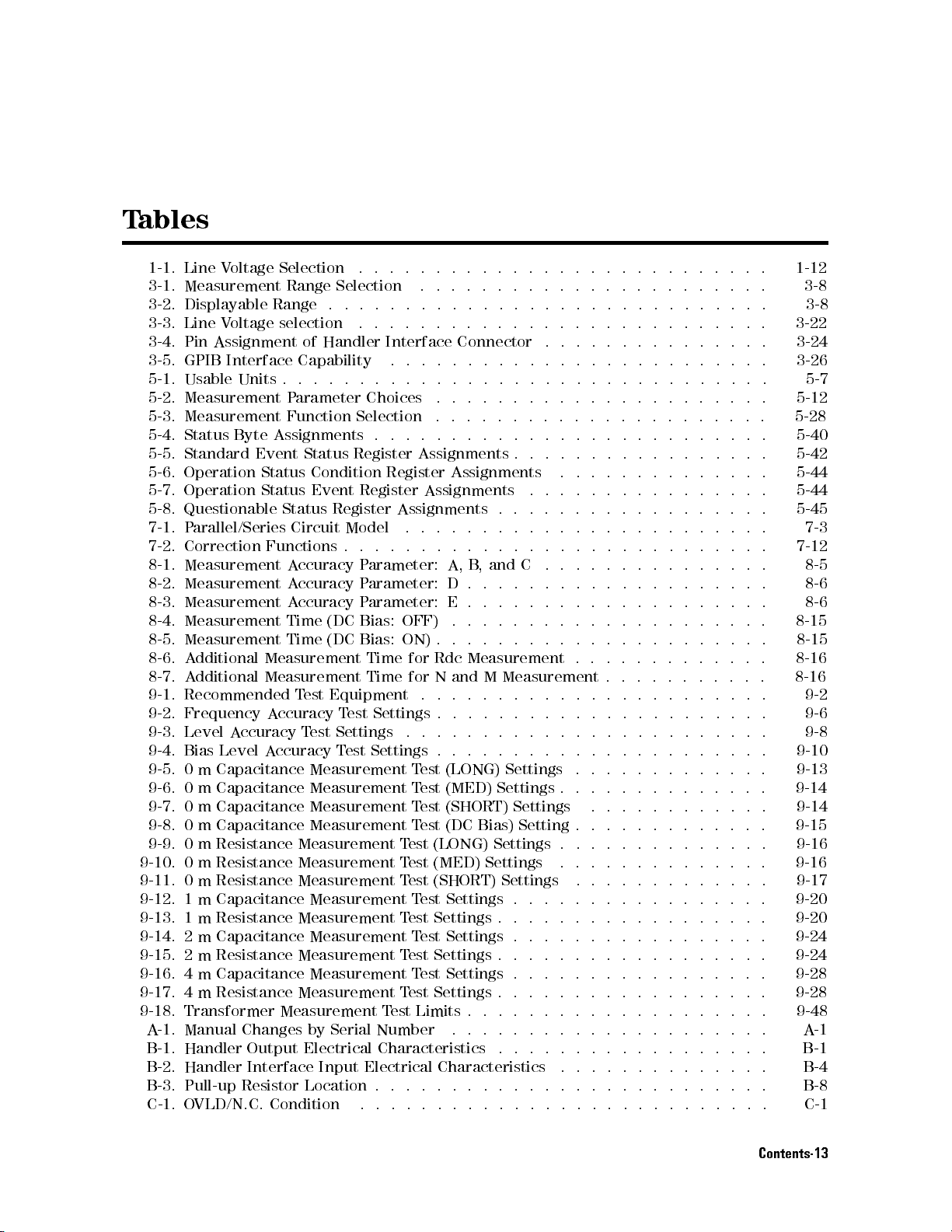
T
ables
1-1. Line
3-1.
3-2.
3-3.
3-4.
3-5.
5-1.
5-2.
5-3.
5-4.
5-5.
5-6. Operation
5-7.
5-8.
7-1.
7-2.
8-1.
8-2.
8-3.
8-4.
8-5.
8-6.
8-7.
9-1.
9-2.
9-3.
9-4.
9-5.
9-6.
9-7.
9-8.
9-9. 0 m Resistance Measurement T
9-10. 0 m Resistance Measurement T
9-11. 0 m Resistance Measurement T
9-12. 1 m Capacitance Measurement T
9-13. 1 m Resistance Measurement T
9-14.
9-15. 2
9-16. 4
9-17. 4 m Resistance Measurement TestSettings.................. 9-28
9-18. Transformer Measurement TestLimits...... ...... ..... ... 9-48
A-1. Manual Changes by Serial Number ... ..... ...... ...... . A-1
B-1. Handler Output Electrical Characteristics .... ...... ...... .. B-1
B-2. Handler Interface Input Electrical Characteristics .............. B-4
B-3. Pull-up Resistor Location . . . . . . . . . . . . . . . . . . . . . . . . . . B-8
C-1. OVLD/N.C. Condition ........................... C-1
Voltage
Measurement
Displayable
Line
V
oltage
Pin
Assignment
GPIB
Interface
Usable
Measurement
Measurement
Status
Standard
Operation
Questionable
P
arallel/Series
Correction
Measurement
Measurement
Measurement
Measurement
Measurement
A
dditional
A
dditional
Recommended
Frequency
Level
A
Bias
Level
0
m
Capacitance
0m
Capacitance Measurement
0m
Capacitance Measurement
0m
Capacitance Measurement
2 m Capacitance Measurement T
m Resistance Measurement T
m Capacitance Measurement T
Selection
Range
Range
selection
of
Capability
Units
.
.
.
P
arameter
Function
Byte
Assignments
Event
ccuracy T
Status
Status Condition
Status
Event
Status
Circuit
Functions
A
ccuracy
A
ccuracy
A
ccuracy
Time
Time
Measurement
Measurement
T
est
A
ccuracy T
est Settings
A
ccuracy
Measurement
.
.
Selection
.
.
.
.
.
.
Handler
.
.
.
.
Choices
Selection
.
Register
Register
Register
Model
.
.
.
P
arameter:
P
arameter:
P
arameter:
(DC
Bias:
(DC
Bias:
Time
Time
Equipment
est Settings
Test
Settings .
.
.
.
.
.
.
Interface
.
.
.
.
.
.
Register
Assignments
.
.
.
OFF)
ON)
for
for
..
est (LONG) Settings . . . .
est (MED) Settings
est (SHORT) Settings
estSettings.................
estSettings..................
.
.
.
.
.
.
.
.
.
.
.
.
..
..
..
..
.
.
.
.
.
.
.
.
.
.
.
.
.
.
..
..
..
..
.
.
.
.
.
.
.
.
..
..
..
..
.
.
.
.
.
.
.
.
.
.
.
.
.
..
..
..
..
.
.
.
.
.
Connector
.
.
.
.
.
.
.
.
.
.
.
.
.
.
.
.
.
.
.
.
.
.
.
.
Assignments
Assignments
Assignments
.
.
.
.
.
.
.
.
.
.
A,
B
,
and
D
.
.
E
.
.
.
.
.
.
.
.
.
Rdc
Measurement
N
and
M
..
..
.
..
..
..
.
.
..
.
Test
(LONG) Settings
T
est
(MED)
T
est
(SHORT)
Test
(DC Bias)
est Settings . . . . . . . . . . . . . . . .
est Settings . . . . . . . . . . . . . . . . .
est Settings . . . . . . . . . . . . . . . . .
Settings
.
.
.
.
.
.
.
.
.
.
.
..
..
.
.
.
.
.
.
.
.
.
.
.
.
.
.
.
.
.
.
.
.
.
.
.
.
.
.
.
.
.
.
.
.
.
.
.
.
.
.
.
.
.
.
.
.
..
C
.
.
.
.
.
..
.
.
.
.
.
..
.
.
.
.
..
.
.
.
.
..
.
.
Measurement
.
.
.
.
.
.
.
.
.
.
.
.
.
.
.
.
.
.
.
.
.
.
.
.
..
.
.
Settings
Setting
.
.....
...... ...... .
.
.
.
.
.
.
.
.
.
.
..
..
..
..
.
.
.
.
.
.
..
..
..
.
.
.
.
.
..
..
.
.
.
.
.
..
.
.
.
.
.
.
.
.
.
.
.
.
.
.
.
.
.
.
.
.
.
.
.
..
..
.
.
.
.
..
..
..
..
.
.
.
.
..
.
.
.
.
.
.
.
.
.
.
.
..
.
.
.
.
.
.
.
.
.
.
.
.
.
.
.
.
.
.
.
.
.
.
.
.
.
.
.
.
.
.
.
.
.
.
.
.
.
..
.
.
.
.
.
..
..
.
.
.
.
.
.
.
.
.
.
.
.
.
.
.
.
.
.
.
.
.
.
.
.
.
.
.
.
.
.
.
.
.
.
.
.
.
.
.
.
.
.
.
.
.
.
.
.
.
.
.
.
.
.
.
.
.
.
.
.
.
.
.
..........
.........
.
..
.
.
.
.
.
.
.
.
.
.
.
.
.
.
..
..
.
.
.
.
.
.
.
.
.
.
.
.
.
.
.
.
.
.
.
.
.
.
.
..
.
.
.
.
.
.
.
.
.
..
.
.
.
.
.
.
.
.
. 3-24
.
.
.
.
.
.
.
.
.
.
.
.
.
.
. 5-44
..
.
.
.
.
.
.
.
.
.
.
.
.
.
.
.
.
.
.
.
.
.
. 9-6
. 9-8
.
.
.
.
.
. 9-14
.
.
. 9-15
. 9-20
. 9-20
1-12
3-8
3-8
3-22
3-26
5-7
5-12
5-28
5-40
5-42
5-44
5-45
7-3
7-12
8-5
8-6
8-6
8-15
8-15
8-16
8-16
9-2
9-10
9-13
9-14
9-16
9-16
9-17
9-24
9-24
9-28
Contents-13
Page 32

C-2.
Simultaneous O
VLD and
N.C.
Condition
.
.
.
.
.
.
.
.
.
.
.
..
..
..
..
C-2
Contents-14
Page 33
1
Getting
This chapter
discusses the
Overview
Guided T
Incoming
V
entilation
our
Inspection
Instruction
P
ower
Cable
Preparation for
Using
Front-P
Basic
Operation
Started
provides
following
of
information
P
anels
topics:
Requirements
for
Cleaning
Turning
anel
Keys
On
to
get
you
started
using
your
4263B
LCR
Meter
.
This
chapter
Getting Started 1-1
Page 34
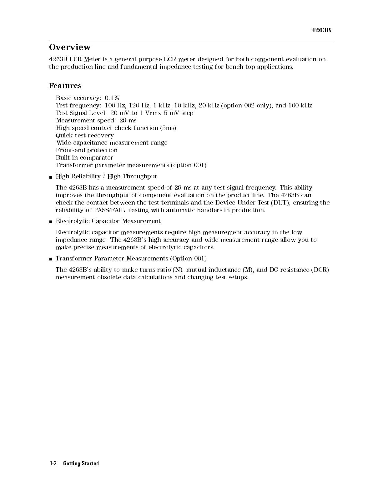
Overview
4263B
4263B
the
F
LCR
production
eatures
Basic
accuracy:
T
est
frequency:
T
est
Signal
Measurement
High
speed
Quick
Wide
test
capacitance
Front-end
Built-in
Transformer
High
Reliability
The
4263B
improves
check
the
reliability
Electrolytic
Electrolytic
impedance
make precise
Meter
line
is
and
0.1%
100
Level:
speed:
contact
recovery
protection
comparator
parameter
/
High
has
a measurement
the
throughput
contact
of
P
ASS/F
Capacitor
capacitor
range
.
measurements
a general
purpose LCR
fundamental impedance
Hz,
120
Hz,
1
kHz,
20
mV
to
1
Vrms
,
29
ms
check
measurement
function
range
(5ms)
measurements
Throughput
speed of
of component
between the
AIL
testing with
test terminals
Measurement
measurements
The
4263B
's
high
accuracy
of
electrolytic
meter designed
testing for
10
kHz,
20 kHz
5
mV step
(option
29 ms
001)
at
any
evaluation on
and the
automatic handlers
require
high
measurement
and
wide
capacitors
.
for both
component evaluation
bench-top applications
(option 002
test
signal
the product
Device Under
in
production.
only), and
frequency
line.
T
est
accuracy
measurement
range
.
The
(DUT),
in
.
100 kHz
This
4263B
the
low
allow
ability
can
ensuring
you
to
on
the
Transformer
The
4263B
's
measurement
P
arameter
ability
obsolete
Measurements
to
make
data
calculations
turns
ratio
(Option
(N),
mutual
and
001)
changing
inductance
test
setups
(M),
.
and
DC
resistance
(DCR)
1-2 Getting Started
Page 35
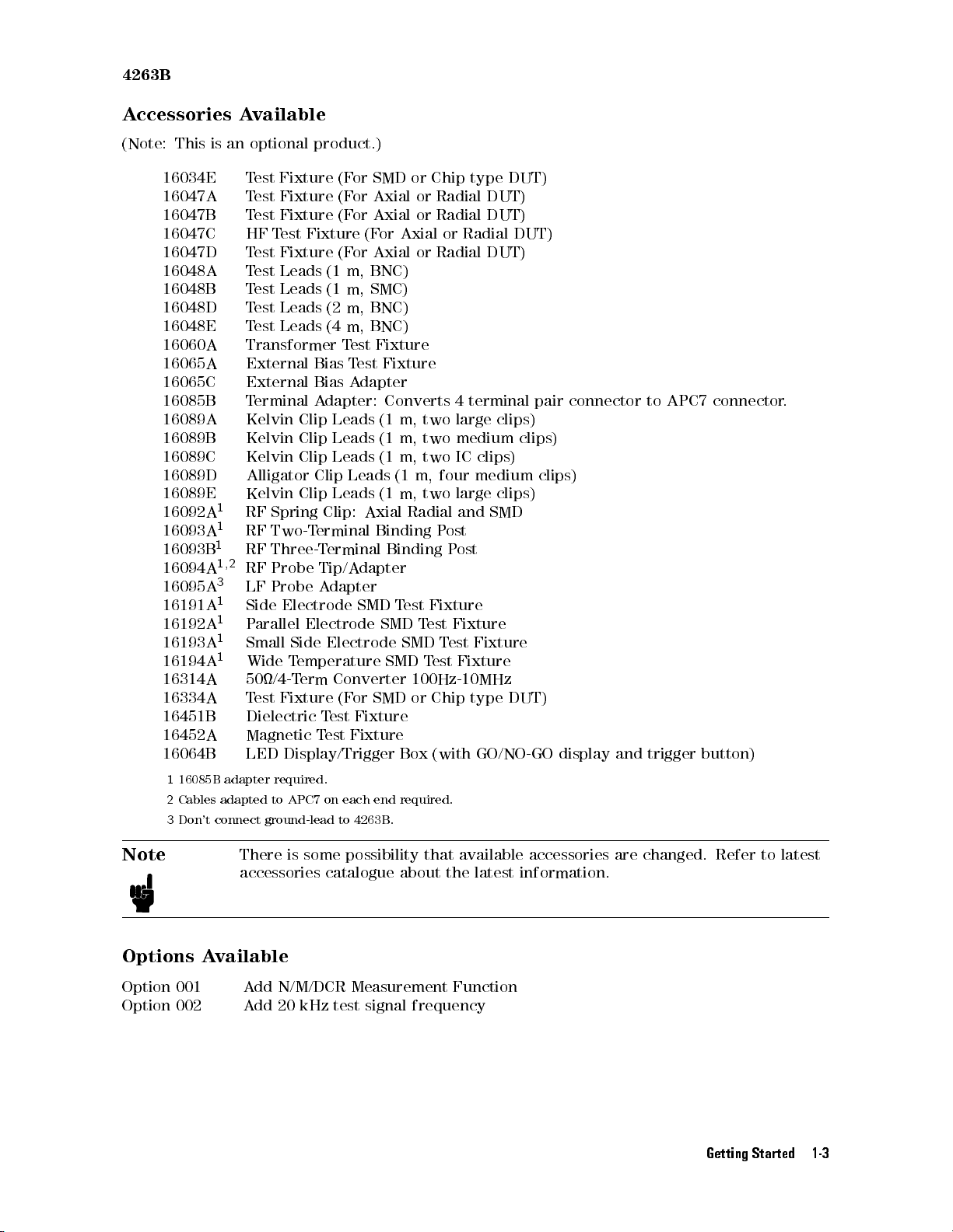
4263B
A
ccessories
A
vailable
(Note:
This
is
16034E
16047A
16047B
16047C
16047D
16048A
16048B
16048D
16048E
16060A
16065A
16065C
16085B
16089A
16089B
16089C
16089D
16089E
16092A1RF
16093A1RF
16093B1RF
16094A
1
16095A3LF Probe
16191A1Side
16192A1P
16193A1Small
16194A1Wide
16314A
16334A
16451B
16452A
16064B
1
16085B adapter
2
Cables
adapted
3
Don't
connect
an
optional
T
est
Fixture (F
Test
Fixture (F
T
est
Fixture (F
HF
T
est Fixture
T
est
Fixture (F
T
est
Leads (1
Test
Leads (1
Test
Leads (2
Test
Leads (4
Transformer T
External Bias
External Bias
Terminal
Kelvin Clip
Kelvin
Kelvin
Alligator
Kelvin
Spring
Two-T
Three-T
,
2
RF
Probe
Electrode SMD
arallel
Side
T
emperature SMD
50/4-T
T
est
Fixture
Dielectric
Magnetic
LED
Display/Trigger
required.
to
APC7 on
ground-lead
product.)
or SMD
or Axial
or Axial
(For
or Axial
m, BNC)
m, SMC)
m, BNC)
m, BNC)
est Fixture
Test
Fixture
A
dapter
A
Clip
Clip
Clip
Clip
Clip:
erminal
Tip/A
A
dapter:
Leads
Leads
Leads
Leads
erminal
dapter
Converts
(1
(1 m,
(1
Leads
(1 m,
Axial
Binding
Binding
dapter
Electrode SMD
Electrode SMD
erm
Converter
(F
or
SMD
T
est
Fixture
T
est
Fixture
each end
to
4263B
or Chip
or Radial
or Radial
Axial or
or Radial
m,
two
two
m, two
(1
m,
four
two large
Radial
P
ost
P
T
est
Fixture
T
est
Fixture
T
est
Test
100Hz-10MHz
or
Chip
Box
(with
required.
.
type DUT)
DUT)
DUT)
Radial DUT)
DUT)
4
terminal
large
clips)
medium
IC
clips)
clips)
medium
clips)
and
SMD
ost
Fixture
Fixture
type
DUT)
GO/NO-GO
pair
clips)
display
connector
and
to
APC7
trigger
connector
button)
.
Note
There is some
possibility that available accessories are changed. Refer to latest
accessories catalogue about the latest information.
Options A
vailable
Option 001 Add N/M/DCR Measurement Function
Option 002 Add 20 kHz test signal frequency
Getting Started 1-3
Page 36
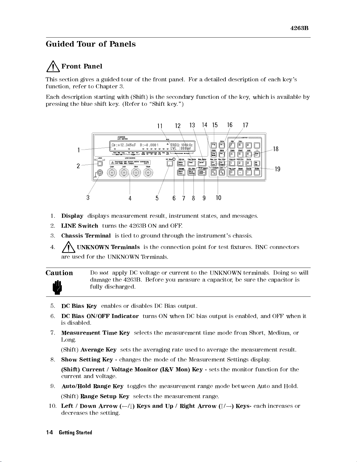
4263B
Guided T
Front
This section
our of
Panel
gives a
function, refer
Each description
pressing the
blue shift
Panels
guided tour
to Chapter
starting with
key.
of the
3.
(Shift) is
(Refer to
front panel.
the secondary
\Shift
key
.")
F
or
function
a
detailed
description
of
the
key
,
which
of
each
is
available
key's
by
1.
2.
3.
4.
Display
LINE
Chassis
are
Switch
T
UNKNO
used
displays
erminal
for
Caution
5.
DC
Bias
Key
6.
DC
Bias
ON/OFF
is disabled.
7.
Measurement Time K
Long.
(Shift)
8.
Show Setting K
Average K
(Shift) Current / V
current and voltage.
turns
WN
the
Do
not
damage
fully
discharged.
enables or
measurement
the
4263B
is
tied
T
erminals
UNKNOWN
apply
DC voltage
the 4263B
disables DC
Indicator
ey
ey
sets the averaging rate
ey -
changes the mode of the Measurement Settings display
oltage Monitor (I&V Mon)
to
ground
is
T
erminals
. Before
result,
ON
the
instrument
and
OFF
.
through
connection
.
or current
you measure
states
the
instrument's
point
to
the
a
,
and
messages
for
test
xtures
UNKNOWN
capacitor
,
chassis
be
Bias output.
turns
ON
when
DC bias
output
is
enabled,
selects the measurement time mode from Short,
used to average the measurement result.
Key -
sets the monitor function for the
.
.
.
BNC connectors
terminals
sure
the
.
capacitor
and
Medium, or
.
Doing
OFF
so
is
when
will
it
9.
Auto/Hold Range Key
(Shift)
10.
Left / Down Arrow ( /#)Keys and Up / Right Arrow ("/!)Keys-
Range Setup Key
toggles the measurement range mode between Auto and Hold.
selects the measurement range.
decreases the setting.
1-4 Getting Started
each increases or
Page 37
4263B
11.
Measurement
(Shift) Deviation
the measurement
12.
Frequency K
Parameter
Key
Measurement Mode
parameters are
ey
sets
the test
selects
the
measurement
(1Mode) K
being set.
signal frequency
ey -
parameter
advances
the
to
be
display
displayed.
page
when
.
13.
14.
15.
16.
17.
18.
19.
(Shift)
Level
(Shift)
Display
K
ey
Bias Setup
Trigger
(Shift)
Delay
Trigger K
Local
(Shift)
Recall
(Shift)
K
ey
A
ddress
K
Save
Primary
the
primary
(Shift)
limit
Secondary
for
Primary
the
primary
(Shift)
limit
Secondary
for
sets
Mode
K
ey
triggers
returns
ey
recalls
K
ey
P
arameter
parameter
the
secondary
P
arameter
parameter
the
secondary
Mode
the
K
ey
ey
K
ey
stores
K
ey
selects
test
signal
Key
selects the
selects
sets
the trigger
the
trigger
a measurement
the
4263B to
sets
the
the
instrument
the
instrument
Upper
Limit
.
P
arameter
parameter
Lower
Limit
.
P
arameter
parameter.
the
display
level.
DC bias
mode from
delay
in
the Local
GPIB
address
state
(Pri
Upper Limit
.
(Pri
Lower
Limit
voltage
time
.
the
Manual
mode from
.
data
from
state
data
High)
(Sec High)
Low)
(Sec
mode.
.
Internal, Manual,
trigger
the
internal
to
internal
K
ey
-
sets
Key
K
ey
-
sets
the
Low)
K
mode
GPIB
memory
the
upper
lower
ey
.
Remote
memory.
- sets
the
comparator
-
sets the
or External.
mode
.
comparator
upper
lower
comparator
.
limit
for
comparator
limit
for
Getting Started 1-5
Page 38
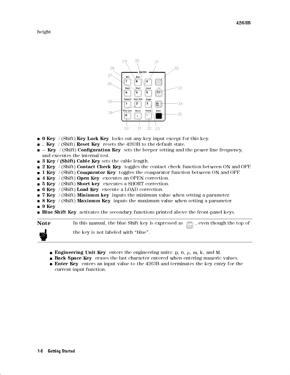
height
0
K
.
K
0
K
and
3
Key
2
Key
1
Key
4
Key
5
K
6
K
7
K
8
K
9
K
Blue
ey
/
(Shift)
ey
/
(Shift)
ey
/
(Shift)
executes
/
(Shift)
/
(Shift)
/
(Shift)
/
(Shift)
ey
/
(Shift)
ey
/
(Shift)
ey
/
(Shift)
ey
/
(Shift)
ey
Shift
K
ey
Lock
Reset K
Conguration K
the
internal
Cable
K
Contact
Comparator
Open
K
Short
Load
key
K
Minimum
Maximum
K
ey
activates
ey
ey
Check
ey
ey
K
ey
locks
resets
test.
sets
the
K
K
ey
executes
executes
execute
key
inputs
K
ey
the
secondary
out
the 4263B
ey
sets
cable
ey
toggles
toggles
an
a
SHORT
a
LO
the
inputs
any
key
to
the beeper
length.
the
the
OPEN
AD
correction.
minimum
the
maximum
functions
input except
the
default
setting and
contact
comparator
correction.
correction.
value
value
printed
state
check
function
when
when
above
for
this
.
the
power
function
between
setting
setting
the
key
.
line
between
ON
a
parameter
a
parameter
front-panel
4263B
frequency
ON
and
and
OFF
.
.
keys
.
,
OFF
.
.
Note
Engineering
Back Space K
Enter K
current input function.
1-6 Getting Started
In this
the
ey
manual,
key
Unit
ey
is
the
blue
Shift
key
is
not
K
labeled
ey
enters
with
the
engineering
expressed
\blue".
units: p
,
as
n,
erases the last character entered when entering numeric values
enters an input value to the 4263B and terminates the key entry for the
,
m,
, even
k,
though
and
M.
the
top
.
of
Page 39
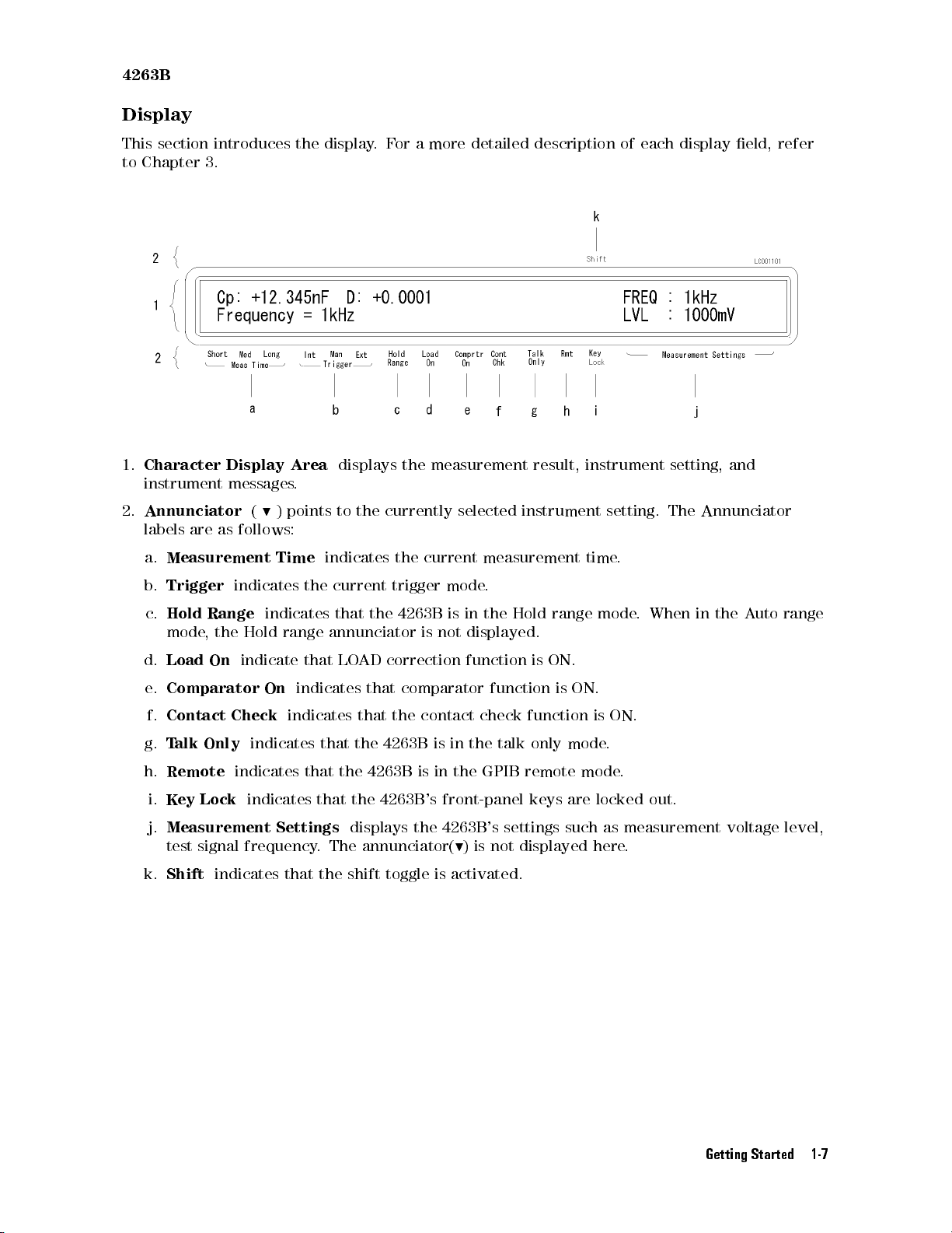
4263B
Display
This
section
to
Chapter
1.
Character
instrument
2.
Annunciator
labels
introduces
3.
Display
messages
are as
(
9
)
follows:
the
Area
.
points
display
displays
to
the
.
F
or
a
more
the measurement
currently
selected
detailed description
result, instrument
instrument
of each
setting.
display eld,
setting, and
The
Annunciator
refer
a.
Measurement Time
b.
Trigger
c.
Hold
mode
d.
Load
e.
Comparator
f.
Contact
g.
T
alk
h.
Remote
i.
K
ey
j.
Measurement
test signal
k.
Shift
indicates
Range
,
the
Hold
On
indicate
Check
Only
indicates
indicates
Lock
indicates
frequency. The annunciator(
indicates
the
indicates
range
that
On
indicates
indicates
that
Settings
indicates
current
that
annunciator
LO
that
the
that
the
trigger
the
AD
correction
that
that
the
the
4263B
4263B
the
4263B
displays
current
mode
4263B
is
is
not
comparator
contact
is
in
is
in
the
's
front-panel
the 4263B
9
) is not displayed here
in
displayed.
function
the
that the shift toggle is activated.
measurement
.
the
Hold
range
is
ON.
function
check
talk
GPIB
is
function
only mode
remote
keys
's settings
time
mode
ON.
is
.
mode
are
locked out.
such as
.
.
When
in
the
ON.
.
measurement voltage
.
A
uto
range
level,
Getting Started 1-7
Page 40
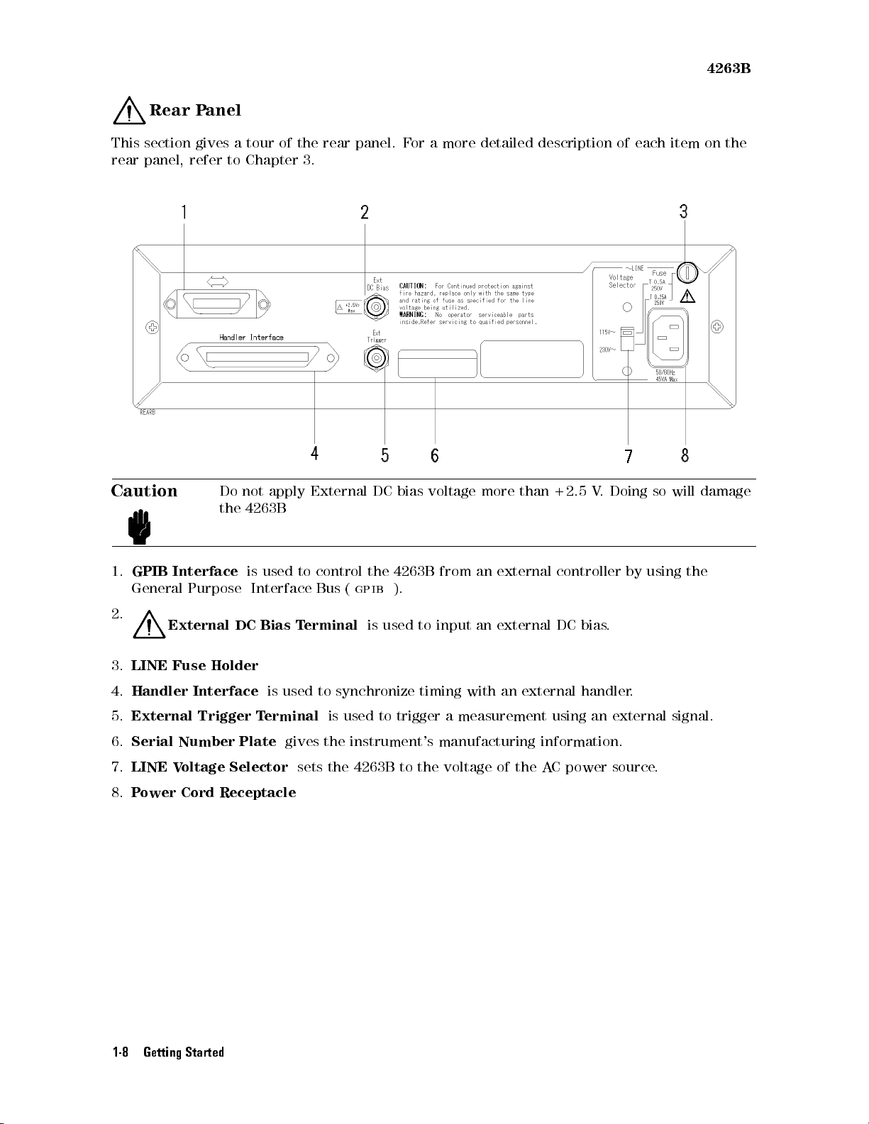
4263B
Rear
This
section
rear
panel,
Caution
P
anel
gives
refer
a
tour of
to
Chapter 3.
Do
not
the
4263B
apply
the rear
External
panel. F
DC
bias
or a
more detailed
voltage
more
description of
than
+2.5
V
.
each item
Doing
so
will
on
the
damage
1.
GPIB
Interface
General Purpose
2.
External
3.
LINE
Fuse
4.
Handler
5.
External
6.
Serial
7.
LINE
8.
Power Cord Receptacle
Number
V
oltage
DC
Holder
Interface
Trigger
Plate
Selector
is
used
Interface
Bias
is
used
T
erminal
gives
to
control
Bus
T
erminal
to
is
the
sets
the 4263B
the
4263B
(
gpib
).
is
used
synchronize
used
to
from
to
input
timing
trigger a
an
an
with
measurement using
instrument's manufacturing
to
the
voltage
external
external
an
external
of
the
controller
DC
bias
.
handler
an external
information.
A
C
power
by
.
source
using
.
the
signal.
1-8 Getting Started
Page 41
4263B
Incoming Inspection
T
Warning
o avoid
are
example
hazardous electrical
signs
of
,
covers
shipping damage
, panel,
or display)
shock, do
to any
portion of
not turn
on the
the outer
4263B when
enclosure (for
there
Inspect the
is damaged,
shipping
it
should
completeness and
the shipment
4263B LCR
P
ower
Operation
User's
If the
contents
not
pass
container is
carrier as
are
Meter
Cable
Manual(This
Guide
are
the
power-on
damaged,
well
as
inspection.
Providing
T
o
ensure
temperature
clearance
the
rack
housing.
measurement
Chapter
clearance
the
specications
around
around
accuracy
8.
container
be
kept
the
4263B
as
follows:
incomplete
selftests
or
the
Agilent
the
product
the
product
F
or
information
of
for
damage
until
the
has
been
Book)
,
if
there
,
notify
the
cushioning
T
echnologies
to dissipate
and
measurement
within
or
,
for
on
the
product,
.
contents
checked
is
mechanical
the
material
the
the
rackmount
ambient
refer
If
the
of
mechanically
nearest
oce
.
heat
accuracy
specied
temperature
to
Specications
shipping
the
shipment
damage
Agilent
shows
Keep
the
range
type
container
have
and
electrically
or
defect,
T
echnologies
signs
of
unusual
shipping
at
installation
of
the
product,
by
providing
,
by
forcefully
to
satisfy
,
and \Measurement
or
cushioning
been
checked
.
The
contents
or
if
the
analyzer
oce
.
If
the
stress
,
notify
materials
for
the
site
you
must
keep
appropriate
air-cooling
inside
the specications
Accuracy"
material
for
of
does
shipping
the
carrier's
ambient
cooling
and
in
When
the
operating
standard.
product
cooling
clearance as
ambient
environment
Furthermore
still conforms
temperature
specication,
,
under that
to the
requirements of
follows:
around
the
the
product
product
is
conforms
temperature environment,
the safety
kept
within
to
the
it has
standard when
the
temperature range
requirements
been conrmed
it is
enclosed with
of
the
safety
that
of the
the
Conditions
Rear 400 mm
Side 100 mm
Upper 15 mm
Instruction for Cleaning
For cleaning, wipe with soft cloth that is soaked with water and wrung tightly without undue
pressure.
Getting Started 1-9
Page 42
4263B
Power
In
accordance
three-wire
the
instrument
country
W
of
arning
Cable
with
power
cable
frame
destination.
F
or
defeated.
protective
international
.
When connected
.
The type
Refer
to Figure
protection
The
earth
safety standards
to an
of power
cable shipped
1-1 for
from
electrical
power
plug
ground
must
connection.
, this
instrument is
appropriate ac
with each
the part
shock,
be
plugged
numbers of
the
equipped with
power outlet,
instrument depends
the power
power
into
cable
an
ground
outlet
a
this cable
grounds
on the
cables available
must
not
that
provides
.
be
a
1-10 Getting Started
Page 43
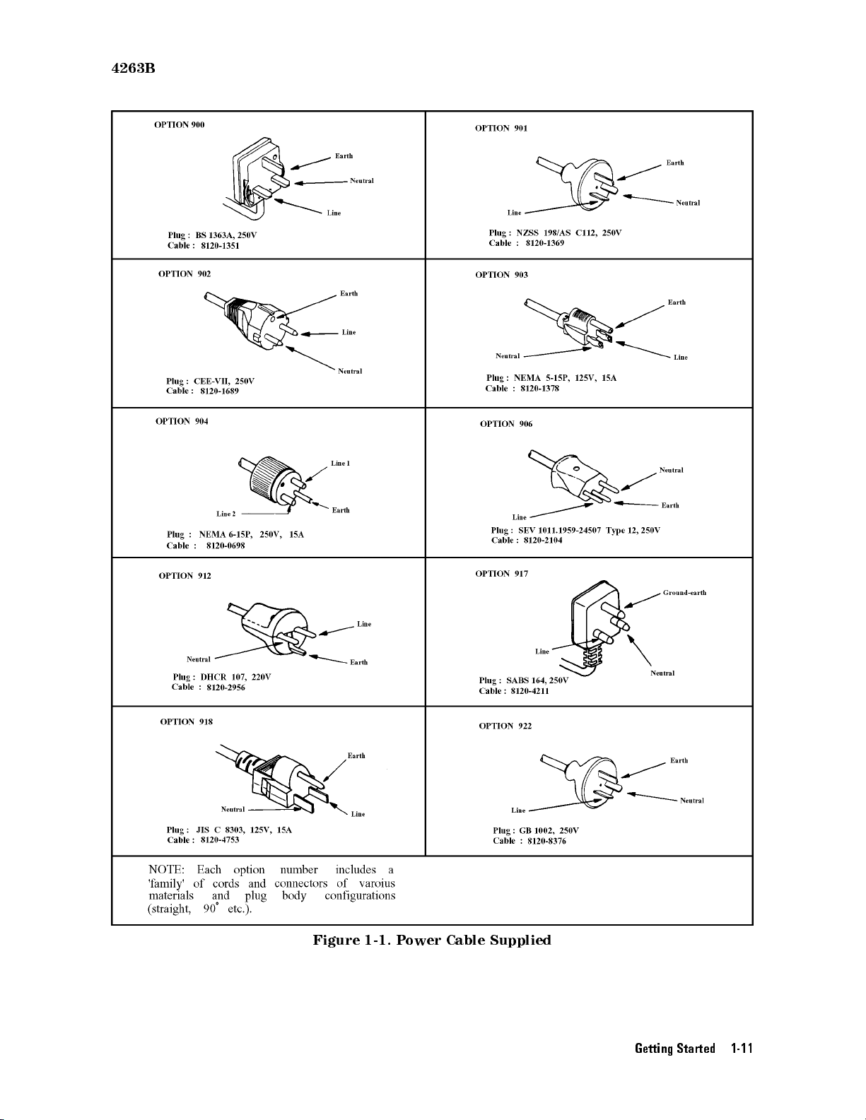
4263B
Figure 1-1. Power Cable Supplied
Getting Started 1-11
Page 44
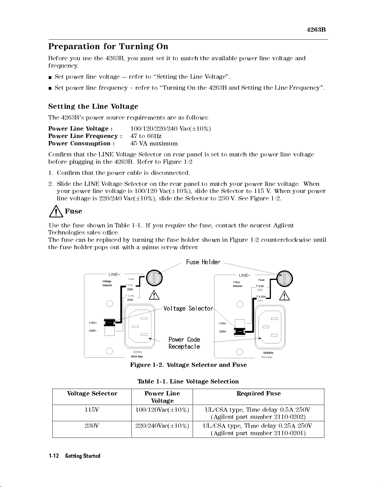
4263B
Preparation for
Before
frequency
Setting
The
P
P
P
Conrm
before
1.
2. Slide
you
Set
power
Set
power
4263B
ower
Line
ower
Line
ower
Consumption
plugging
Conrm
your
line
voltage
use
.
line
line
the Line
's
power
V
oltage
Frequency
that
the
that
the
LINE
power
line
is
the
4263B,
voltage
frequency
V
source
:
LINE
in
the
the
power
V
oltage
voltage
220/240
Fuse
Use
the
fuse
T
echnologies
The
fuse
the
fuse
shown
sales
can
holder
be
in
oce
replaced
pops
out
Turning On
you must
| refer
to \Setting
{refer
oltage
requirements
100/120/220/240
:
47
to
66Hz
:
45
V
A
maximum
V
oltage
4263B
T
able
Selector
.
Refer
cable
Selector
is
100/120
V
ac(
6
10%),
1-1
is
disconnected.
on
.
If
.
by
turning
with
a
minus
set it
to match
the Line
to \Turning
are
as
V
on
rear
to
Figure
the
rear
V
ac(
6
10%),
slide
the
you
require
the
fuse
screw
driver
On the
follows:
ac(
6
panel
1-2
panel
slide
Selector
the
holder
the available
Voltage
4263B and
10%)
is
set
to
to
match
the
Selector
to
230
fuse
,
contact
shown
in
.
".
match
your
V.
Figure
power line
Setting
the
the power
power
to 115
See Figure
the
nearest
1-2
counterclockwise
voltage and
Line
line voltage
line
voltage
V.
When your
1-2.
Agilent
Frequency".
.
When
power
until
Figure 1-2. V
Table 1-1. Line V
Voltage Selector Power Line
115V 100/120Vac(610%) UL/CSA type, Time delay 0.5A 250V
230V 220/240Vac(610%) UL/CSA type, TIme delay 0.25A 250V
1-12 Getting Started
oltage Selector and Fuse
oltage Selection
Required Fuse
Voltage
(Agilent part number 2110-0202)
(Agilent part number 2110-0201)
Page 45
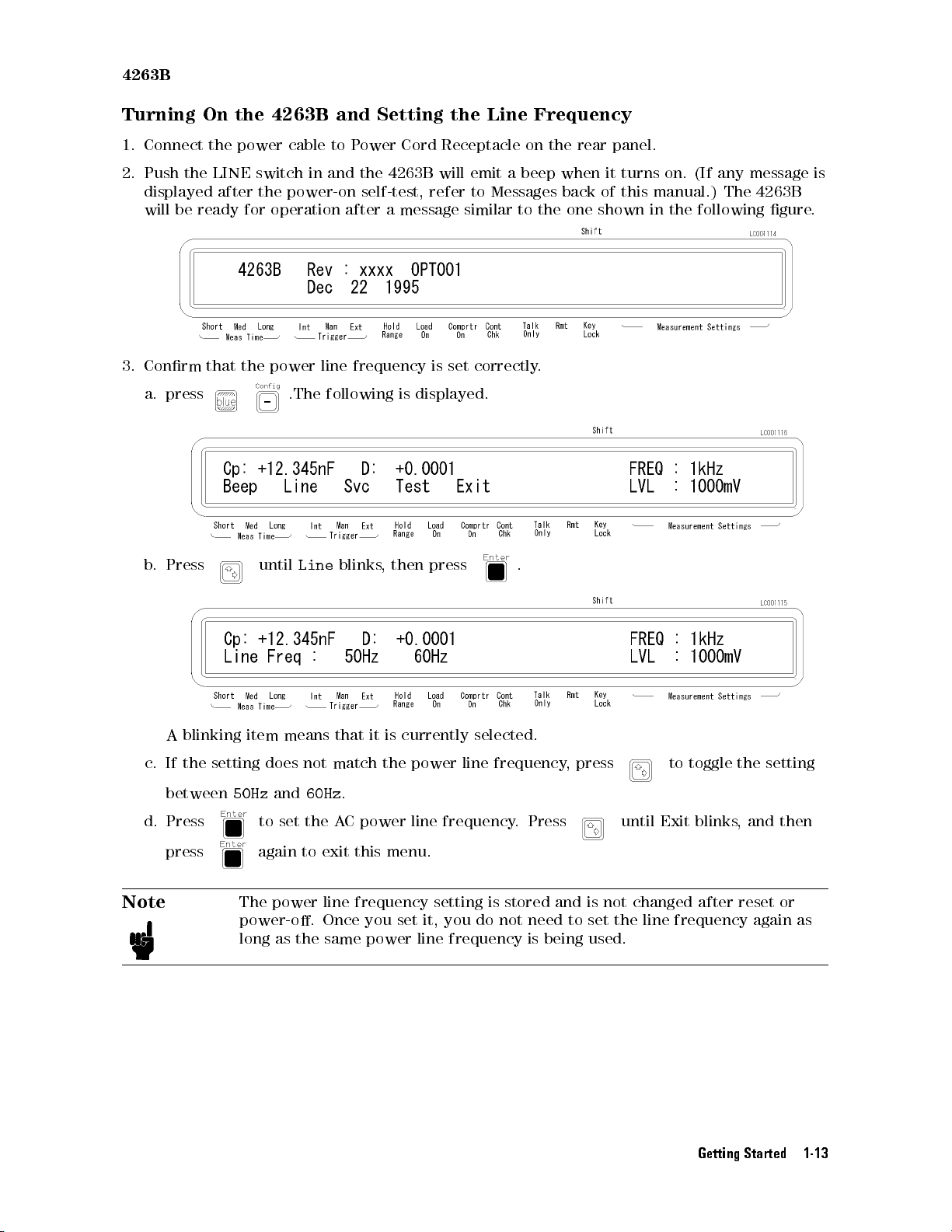
4263B
Turning
1.
Connect the
2.
Push the
displayed
will
be ready
3. Conrm
a. press
b.
Press
On
the
4263B
power cable
LINE switch
after the
for operation
that the
power line
until
and
Setting
to P
ower Cord
in and
the 4263B
power-on self-test,
after a
message similar
frequency
.The following
Line
blinks
is displayed.
,
then
the
Line
Receptacle on
will emit
refer to
is
set
a beep
Messages back
correctly
press
Frequency
the rear
when it
to the
one
.
.
panel.
turns
of this
shown
on.
(If
any
manual.) The
in
the
following
message
4263B
gure
is
.
c.
d.
Note
A
blinking
If
the
setting
between
Press
press
item
50Hz
does
to
means
and
set
not
60Hz
the
that
match
.
A
C
power
it
is
the
currently
power
line
frequency.
selected.
line
frequency
Press
,
press
until
to
Exit
toggle
blinks
the
,
and
setting
then
again to exit this menu.
The power line frequency setting is stored and is not changed
after reset or
power-o. Once you set it, you do not need to set the line frequency again as
long as the same power line frequency is being used.
Getting Started 1-13
Page 46
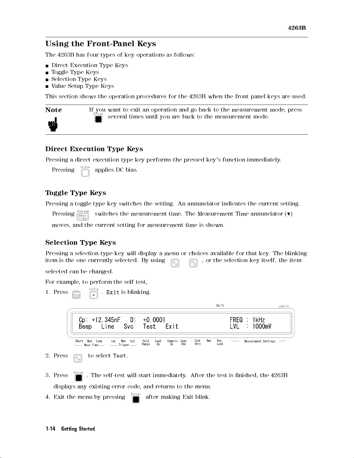
4263B
Using the
The
4263B
Direct
T
oggle
Selection
V
alue
This
section
has
Execution
Type
Type
Setup
shows
Note
Direct
Pressing
Execution
a
direct
Pressing
T
oggle
Pressing
Type
a
toggle
Front-Panel
four
types of
Type
key operations
Keys
Keys
Keys
Type
Keys
the
operation procedures
If
you
want
to
several
Type
execution
applies
K
eys
type
key
type
DC
bias
switches
exit
times
K
eys
Keys
an
until
key
performs
.
the
as follows:
for the
operation
you
are
setting.
4263B when
and
go
back
back
to
the pressed
An
annunciator
the front
to
the
measurement
the
measurement
key's function
indicates
panel
keys
mode
mode
.
immediately
the
current
are
used.
,
press
.
setting.
Pressing
moves
,
and
Selection
Pressing
item
selected
F
or
1.
is
the
example
Press
a
can
selection
one
the
Type
currently
be
changed.
,
to
switches
current
K
eys
type
perform
.
Exit
2. Press to select
3. Press
. The self-test will start immediately. After the test is nished, the 4263B
the
setting
key
will
selected.
the
self test,
is
blinking.
Test
.
measurement
for
measurement
display
By
a
using
time
menu
.
or
The
time
choices
Measurement
is shown.
available
,
or
the
selection
Time
for
that
annunciator
key
.
The
key
itself,
(
9
blinking
the
item
)
displays any existing error code, and returns to the menu.
4. Exit the menu by pressing after making Exit blink.
1-14 Getting Started
Page 47
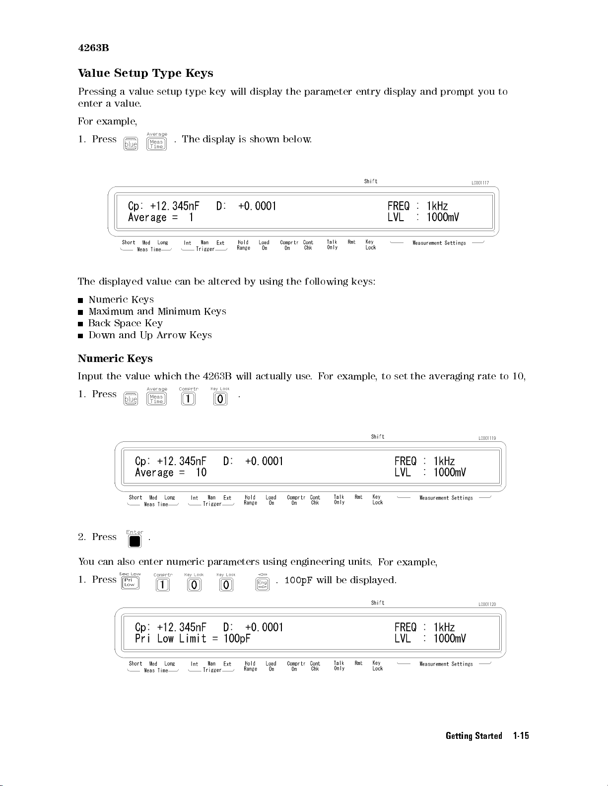
4263B
V
alue
Setup
Type
K
eys
Pressing
enter
a
value
F
or
example
1.
Press
The
displayed
Numeric
Maximum
Back
Space Key
Down
Numeric
Input
the
a
value
and
K
value
.
,
value
Keys
and
Up
eys
which
setup
type
.
The
display
can
be
Minimum
Arrow Keys
the
4263B
key
altered
Keys
will
will
display
is
shown
by
below
using
actually
the
parameter
the
following
use
.
.
F
or
entry display
keys:
example
and prompt
,
to
set
the
averaging
you to
rate
to
10,
1.
2.
Press
Press
.
.
You can also enter numeric parameters using engineering units
1. Press
.
100pF
will be displayed.
.F
or example
,
Getting Started 1-15
Page 48
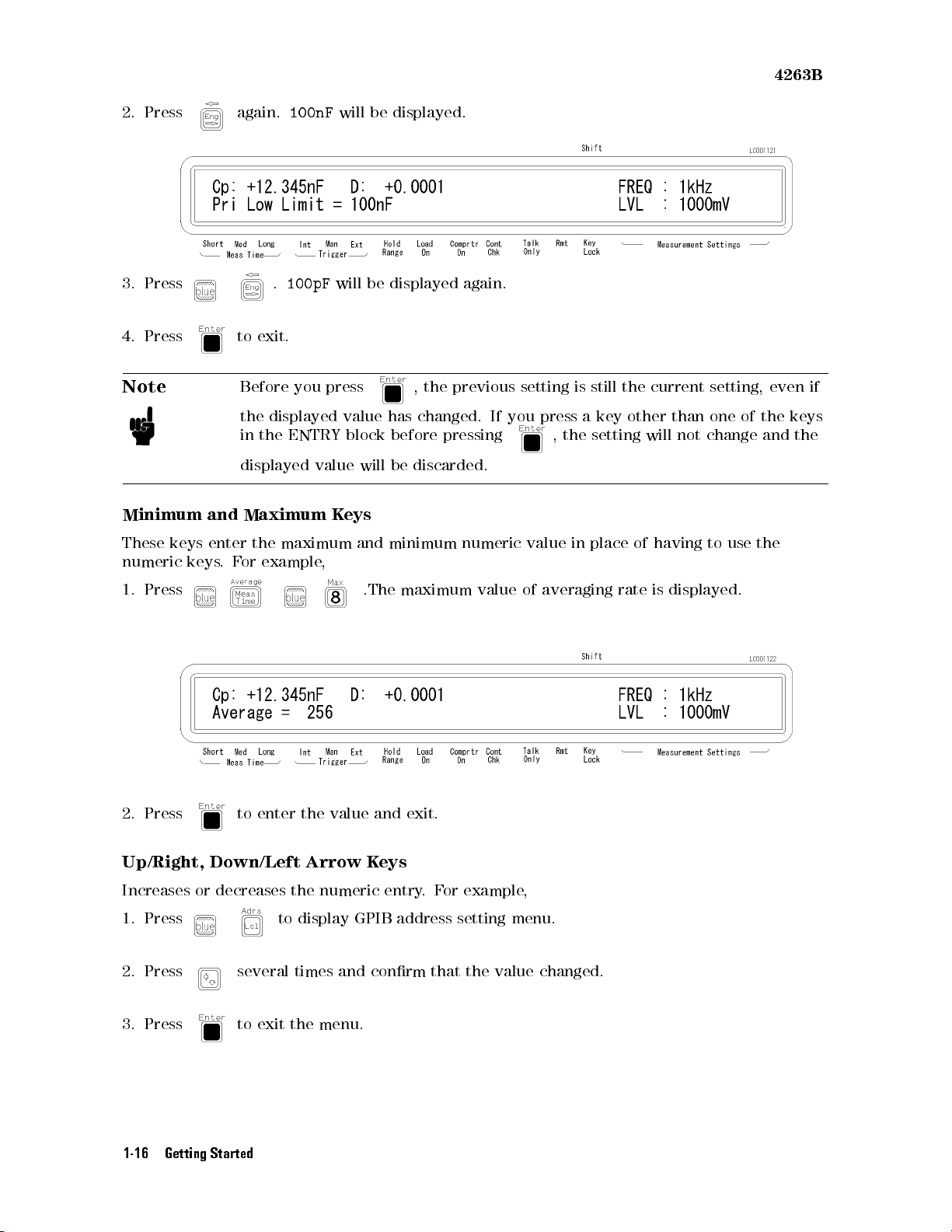
4263B
2.
Press
3.
Press
4.
Press to
Note
Minimum
These
numeric
keys
keys
and
enter
.
F
again.
Before
the
in
displayed
or
100nF
.
100pF
exit.
you press
displayed
the ENTRY
value
Maximum
the
maximum
example
,
will
be displayed.
will
be
value
block
will
K
eys
and
displayed
,
the previous
has
changed.
before
be
pressing
discarded.
minimum
again.
If
you
numeric
setting is
press
,
the setting
value
in
still
a
key
place
the
other
of
current
than
will
not
having
setting,
one
of
change
to
use
the
and
the
even
keys
if
the
1.
Press
2.
Press
to
enter the
Up/Right, Down/Left Arrow K
Increases or decreases the numeric entry
1. Press
to display GPIB address setting menu.
value
.The
and
eys
maximum
exit.
.F
or example,
value
of
averaging
2. Press several times and conrm that the value changed.
3. Press to exit the menu.
rate
is
displayed.
1-16 Getting Started
Page 49
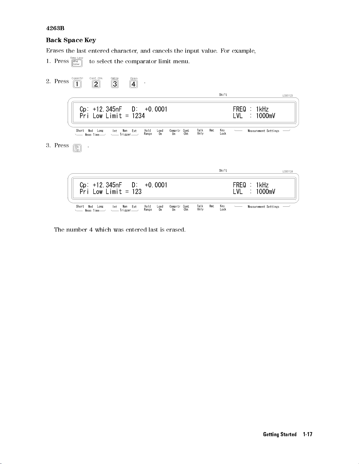
4263B
Back
Space K
ey
Erases
1.
Press
2.
Press
3.
Press
the last
entered
to
select the
.
character
comparator
,
and
.
cancels
limit
the
input
menu.
value
.
F
or
example,
The
number
4
which
was
entered
last
is
erased.
Getting Started 1-17
Page 50
Basic Operation
The
following
1.
Conguration
2.
Turning
3.
Settting
4.
Error
5.
Connecting
6.
Measurement
This
section
and
become
procedure
setup
on
the
parameters
correction
the
provides the
familiar with
4263B
DUT
is
commonly used
to the
test xture
basic measurement
the 4263B
's operation.
to perform
procedure of
a measurement
the
4263B
using the
.
F
ollow
4263B:
the
instructions
4263B
Connecting
Resetting
Selecting the
Selecting
Selecting
Seting
Matching
P
erforming
Caution
Note
the
a
Test
Fixture
the
4263B
Measurement P
the
T
est
Signal
the
Measurement
T
est
V
oltage
the
Cable
the
OPEN,
Do
not
damage
fully
discharged.
If
you
Problem
Frequency
Length
SHORT
apply
the
have
"in
arameter
Range
of
T
est
Fixture
and
DC voltage
4263B
.
Before
any
problems
Chapter 2.
LO
AD
Correction
or current
you
measure
operating
to
the
the
UNKNOWN
a
capacitor
4263B
,
refer to
,
be
terminals
sure
the
\If
Y
ou
.
Doing
capacitor
Have
a
so
will
is
1-18 Getting Started
Page 51
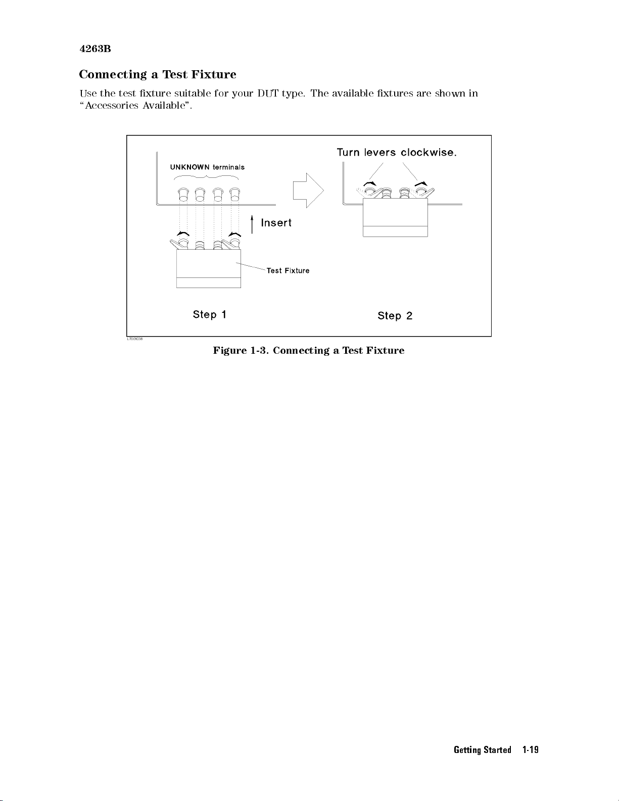
4263B
Connecting
Use
the
test
xture
\A
ccessories
a
T
A
vailable
est
Fixture
suitable
".
for
your
Figure
DUT
1-3.
Connecting
type
.
The available
a
T
est
xtures are
Fixture
shown in
Getting Started 1-19
Page 52
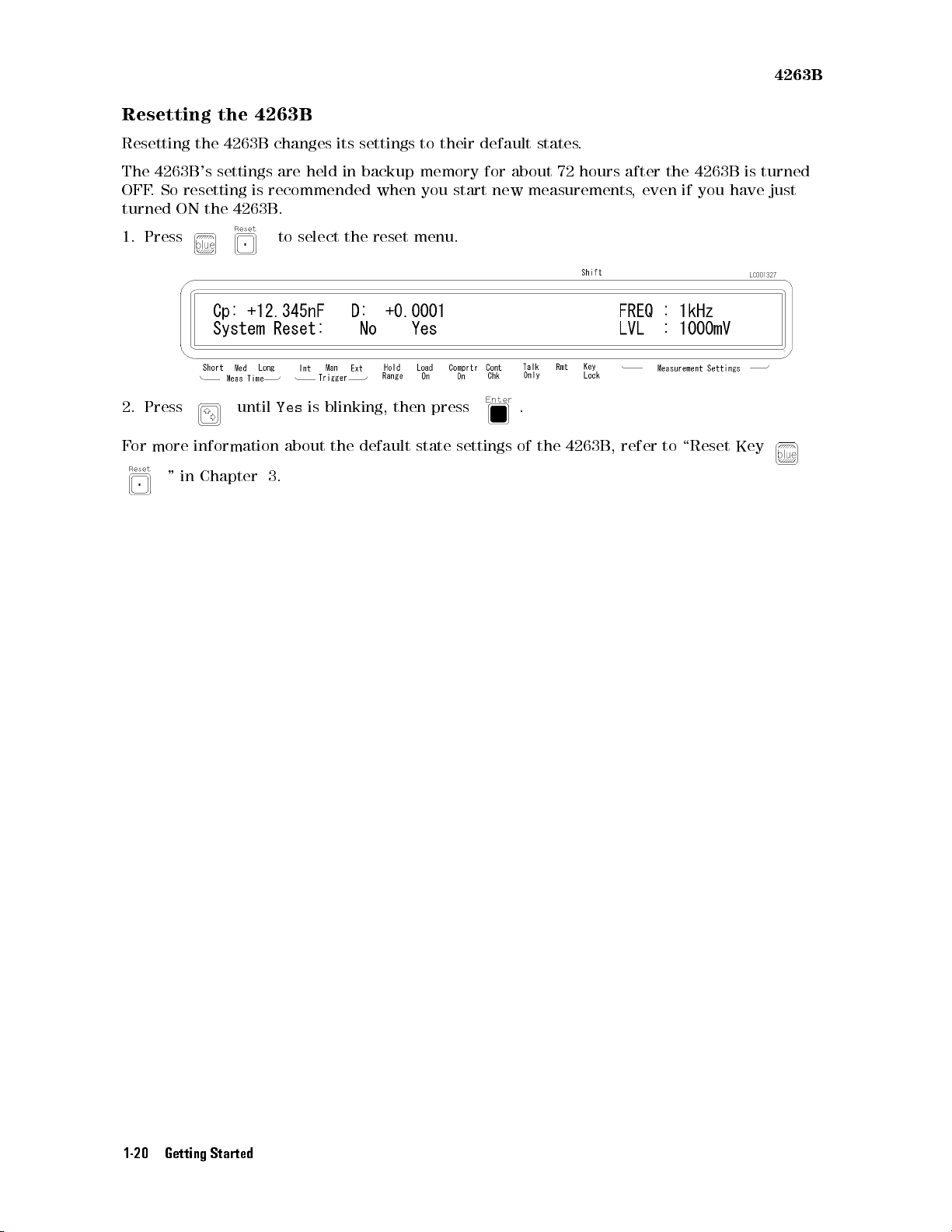
4263B
Resetting
Resetting
The
OFF
turned
1.
Press
2.
Press
F
or
4263B
.
So
ON
more
"
the
resetting
information
in
the
4263B
's
settings
the
4263B
until
Chapter
4263B
changes
are
held
is
recommended
.
to
select
Yes
is
blinking,
about
3.
its
settings
in backup
when you
the
reset
the
default
to
their
memory for
menu.
then
press
state
default
start new
settings
states
.
about 72
hours after
measurements,
.
of
the
4263B
,
refer
the 4263B
even if
to
you have
\Reset
is turned
just
Key
1-20 Getting Started
Page 53
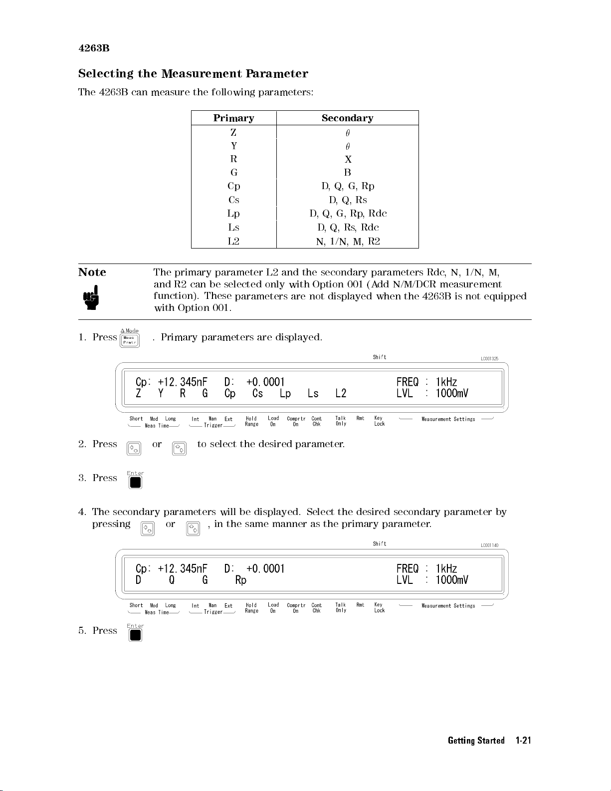
4263B
Selecting
The
4263B
Note
1.
Press
the
Measurement
can
measure
The
primary parameter
and
R2
function).
with
.
Primary
the
can
Option
P
arameter
following
parameters:
Primary Secondary
Z
Y
R X
G B
Cp D
Cs D
Lp D
Ls D
L2 N,
L2 and
be
selected
These
only
parameters
with Option
are not
,
Q,
the
secondary
,
Q,
,
G,
,Q,
1/N,
displayed
001.
parameters
are
displayed.
Q,
Rs,
G,
Rs
Rp
M,
001
Rp
,
Rdc
Rdc
R2
parameters
(A
dd
N/M/DCR
when
the
Rdc
,
N,
measurement
4263B
is
1/N,
not
M,
equipped
2. Press or to select
3.
Press
4.
The secondary
pressing
parameters will
or ,
in the
5. Press
the desired
be
displayed.
same manner
parameter
Select
as the
.
the
desired
secondary
primary parameter
parameter
.
by
Getting Started 1-21
Page 54
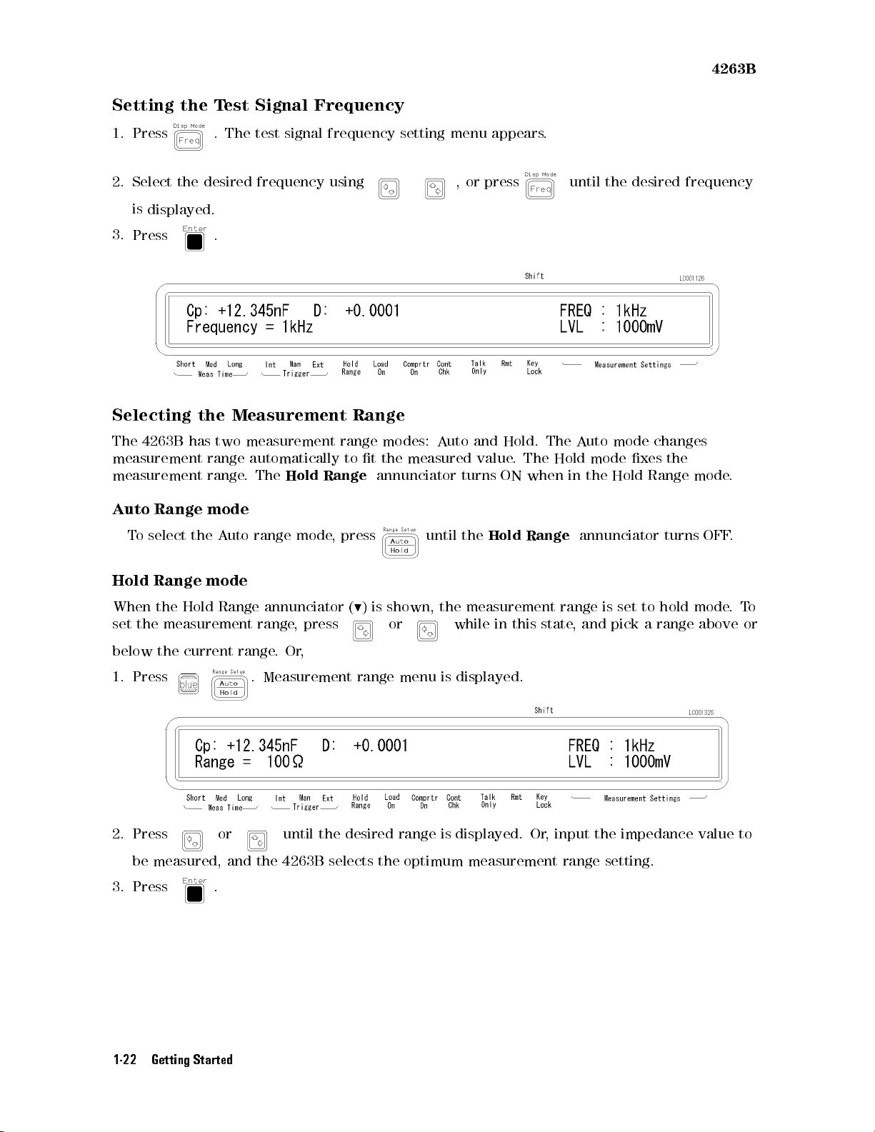
4263B
Setting
1.
Press .
2. Select
is
3.
Press .
the
the desired
displayed.
Selecting
The
4263B has
measurement
measurement
A
uto Range
T
est
Signal
The test
signal frequency
frequency using
the
Measurement
two measurement
range automatically
range.
The
Hold
mode
Frequency
Range
range
modes:
to t
the measured
Range
annunciator
setting menu
,or
A
uto
and
turns
appears.
press
Hold.
value
ON
.
The
The
when
until the
A
Hold
in
uto
mode
the
desired frequency
mode
changes
xes
the
Hold
Range
mode
.
T
o
select
Hold
When
set
the
below
1.
Press
2. Press or until the
the
A
Range
the
Hold
mode
Range
measurement
the current
uto
range
mode
annunciator
range
,
press
range.
Or
,
.
Measurement range
,
press
(
9
)
is
shown, the
or while
menu is
desired range is displayed. Or
be measured, and the 4263B selects the optimum
3. Press .
until
the
Hold
Range
measurement range
in
this
state
displayed.
, input the impedance value to
measurement range setting.
annunciator
is set
,
and
pick
to
a
turns
hold
range
OFF
mode
above
.
.
T
o
or
1-22 Getting Started
Page 55
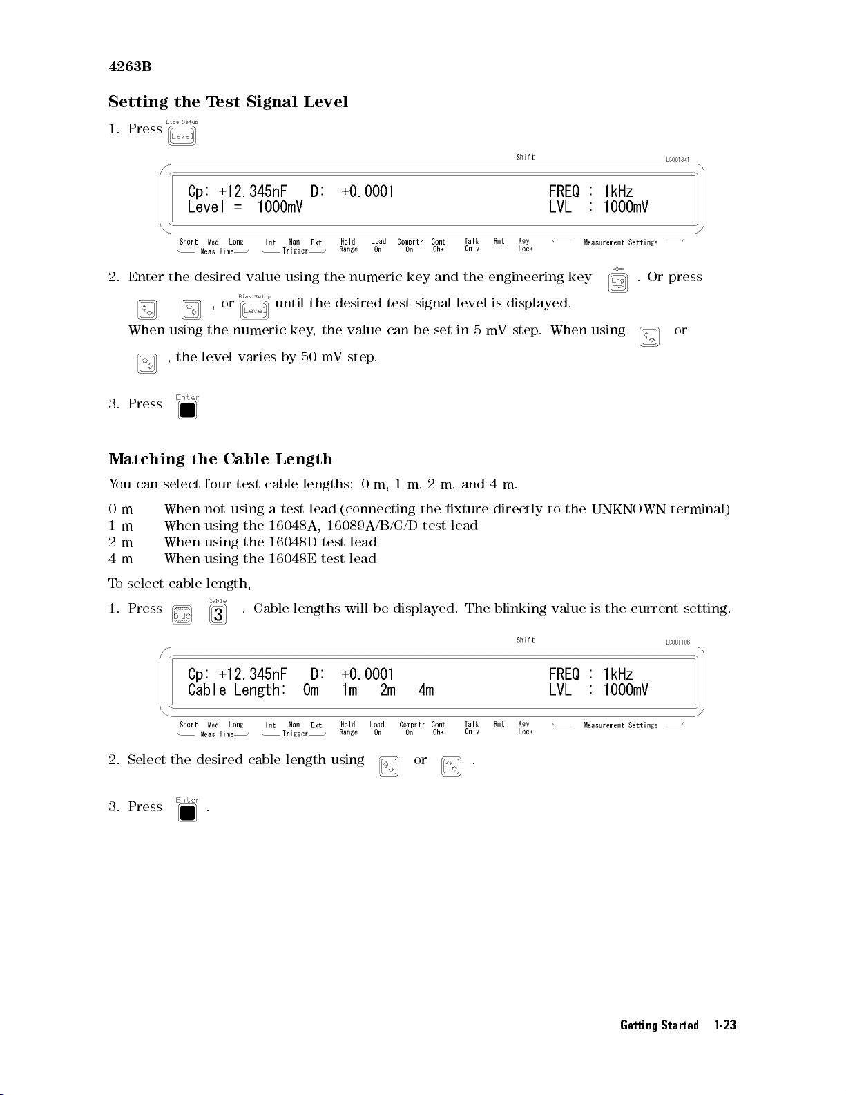
4263B
Setting
1.
Press
2.
Enter
When
the
the
using
,
3.
Press
Matching
Y
ou
can select
desired
the
the
T
est
,
or
the
numeric
level
varies
Cable
four test
Signal
value
until
by
Length
cable
Level
using
key
50 mV
lengths:
the
,
the
desired
the
numeric
test
value
can
step.
0
m,
1
key
signal
be
m,
and
set in
2
m,
the
engineering
level
5mV
and
is
displayed.
step.
4
m.
key
When
using
.
Or
press
or
0
m
1
m
2
m
4
m
T
o
select
When
When
When
When
cable
1. Press
2. Select the
desired cable length using
3. Press .
not
using a
using
using
using
length,
test
lead
the 16048A,
the
16048D test
the
16048E
. Cable
lengths
(connecting
16089A/B/C/D
lead
test
lead
will
be
displayed.
the
xture
test
lead
or .
The
directly
blinking
to
the
value
UNKNOWN
is
the
current
terminal)
setting.
Getting Started 1-23
Page 56
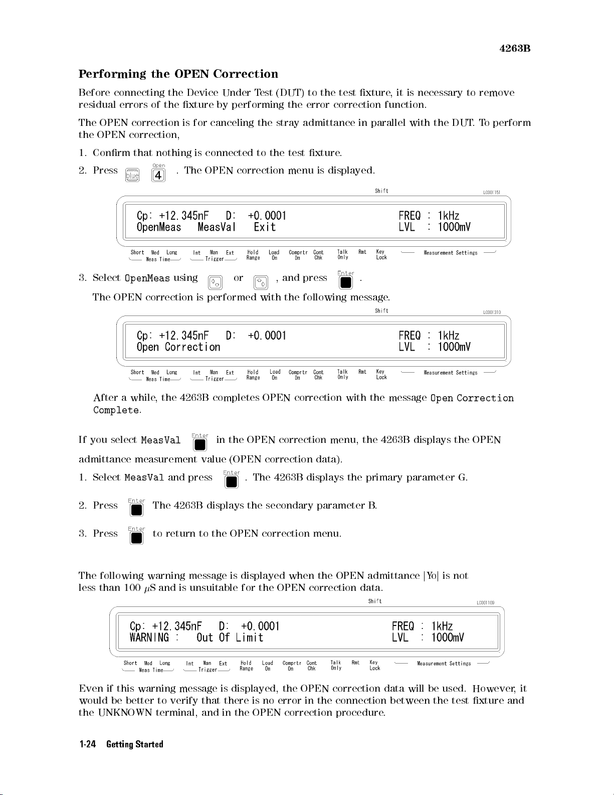
P
erforming
the
OPEN
4263B
Correction
Before
residual
The
OPEN
the
OPEN
1.
Conrm
2.
Press
3.
Select
The
connecting
errors
of
correction
correction,
that
nothing
OpenMeas
OPEN
correction
the
the
Device
xture
is
.
The
using
by
for
canceling
is
connected
OPEN
is
performed
Under
T
est
performing the
the stray
to
the
correction
or ,
with
(DUT)
to
error correction
admittance in
test
xture
menu
and
press
the
following
the
test xture
.
is
displayed.
parallel with
.
message
,it
is necessary
function.
.
the DUT
to remove
.T
o perform
After
a
while
,
the
4263B
Complete
If
you
admittance
1.
Select
2.
Press
3.
Press
.
select
MeasVal
measurement
MeasVal
The
to
and
4263B
return
The following warning message
less than 100
S
and is unsuitable for the OPEN correction data.
value
press
to the
completes
in
the
(OPEN
displays
OPEN correction
OPEN
.
The
the
OPEN
correction
correction
correction
4263B
secondary
menu,
data).
displays
parameter
menu.
with
the
the
is displayed when the OPEN admittance
the
message
4263B
primary
B
.
Open
displays
parameter
jYoj
is not
Correction
the
OPEN
G.
Even if this warning message is displayed, the OPEN correction data will be used. However,it
would be better to verify that there is no error in the connection between the test xture and
the UNKNOWN terminal, and in the OPEN correction procedure.
1-24 Getting Started
Page 57
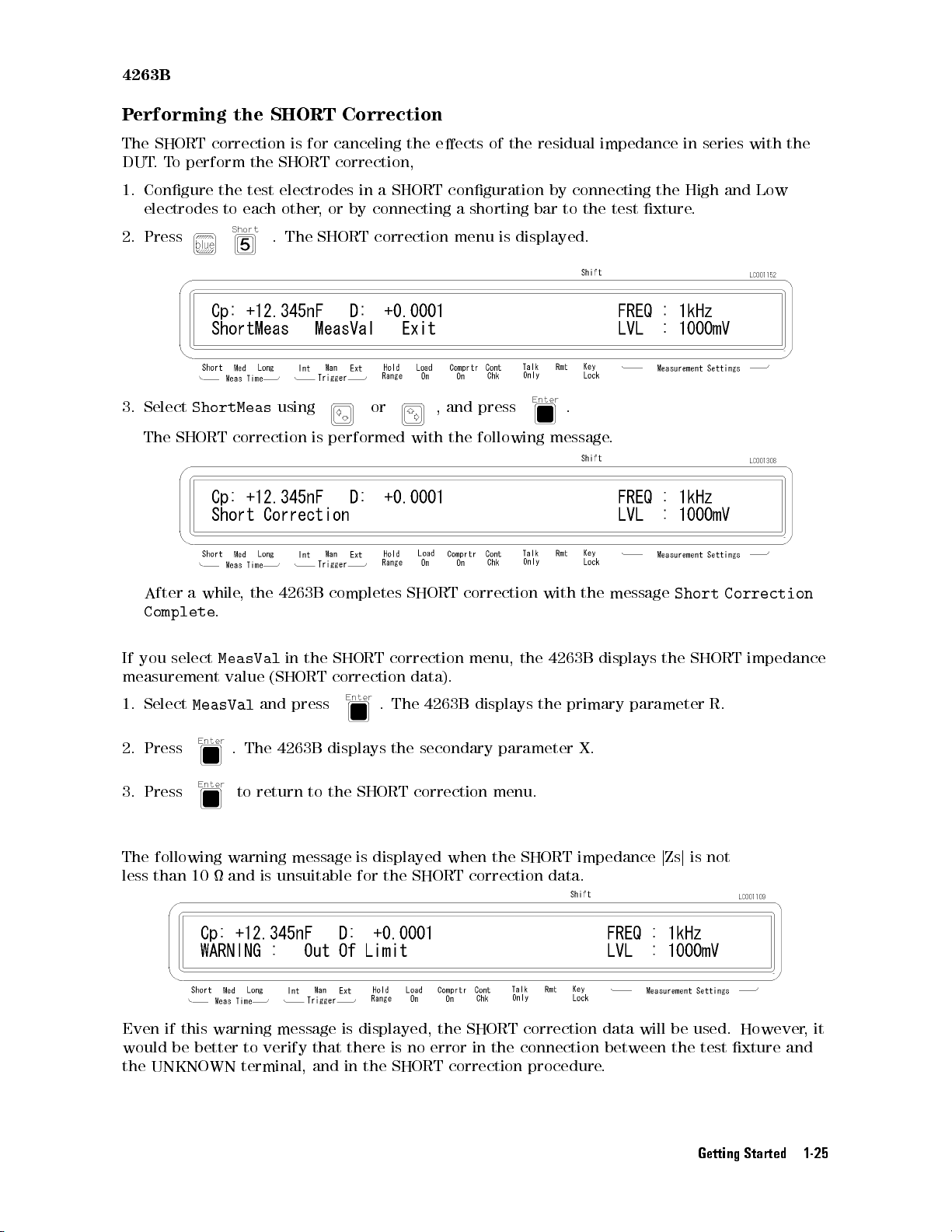
4263B
P
erforming
The
SHORT
DUT
.
T
o
perform
1.
Congure
electrodes
2.
Press
the
SHORT
correction
the
the
test
to
each
.
Correction
is
for
canceling
SHORT correction,
electrodes
other
The
in
,
or
by connecting
SHORT
correction
a SHORT
the
eects
conguration by
a shorting
menu
of
the
is
displayed.
residual impedance
connecting the
bar to
the test
xture.
in series
High and
with the
Low
3.
Select
The
After
ShortMeas
SHORT
a
while
Complete
If
you
select
measurement
1.
Select
2.
Press
3.
Press to
MeasVal
correction
,
the
.
MeasVal
value
and
.
The
return
using
is
4263B
in
the
(SHORT
press
4263B
to the
or ,
performed
completes
SHORT
correction
displays
with
SHORT
correction
data).
.
The
the
SHORT correction
and
press
the
following
correction
menu,
4263B
displays
secondary
with
the
4263B
the
parameter
menu.
.
message
the
.
message
displays
primary parameter
X.
The following warning message is displayed when the SHORT impedance
less than 10 and is unsuitable for the SHORT correction data.
Short
the
Correction
SHORT impedance
R.
jZsj
is not
Even if this warning message is displayed, the SHORT correction data will be used. However,it
would be better to verify that there is no error in the connection between the test xture and
the UNKNOWN terminal, and in the SHORT correction procedure.
Getting Started 1-25
Page 58
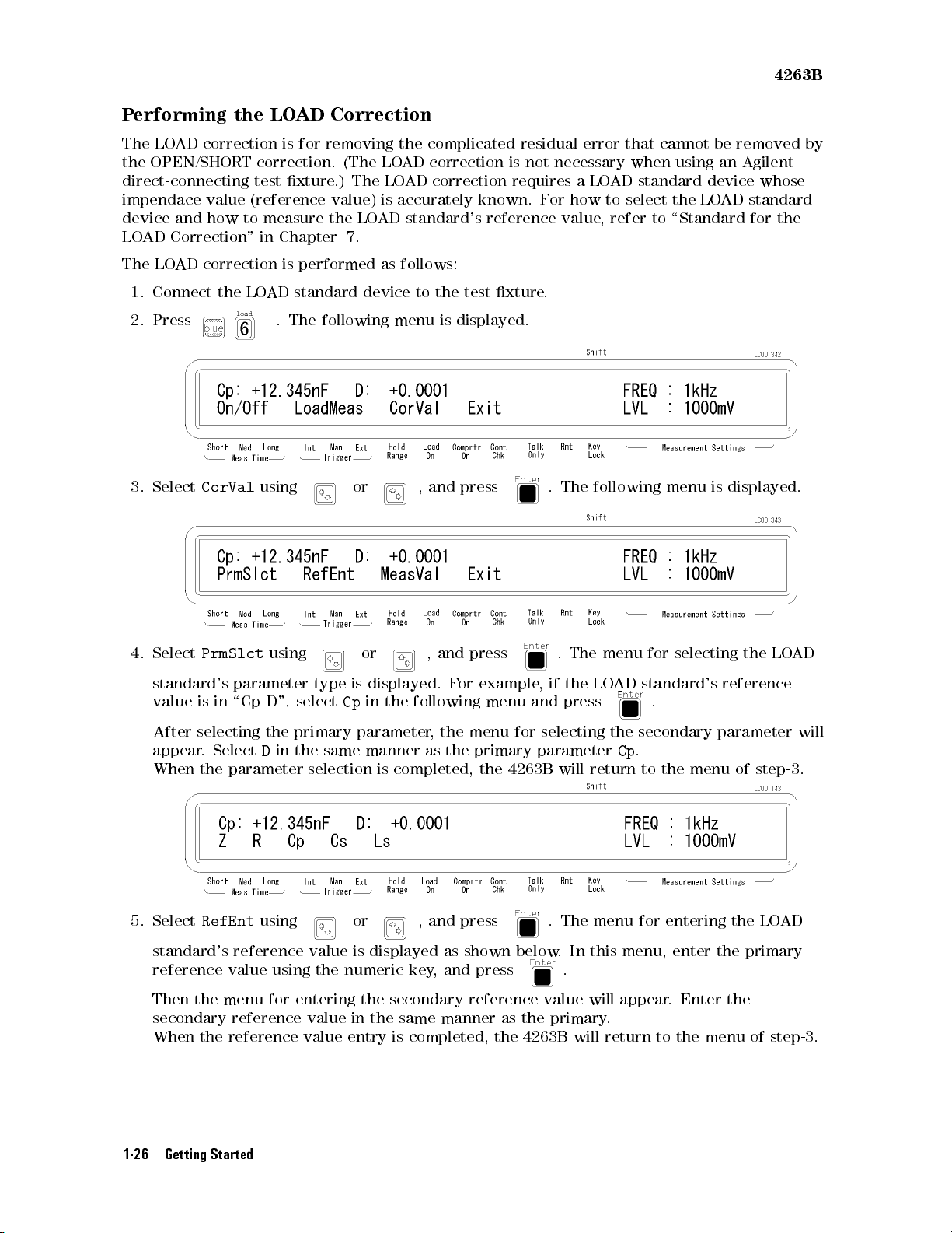
P
erforming
The
LO
AD
the
OPEN/SHORT
the
correction
direct-connecting
impendace
device
LO
AD
The
LO
1.
Connect
2.
Press
value
and
how
Correction
AD
correction
the
LO
AD
is
correction.
test
xture
(reference
to
measure
"
in
Chapter
is
LO
AD
standard
.
The
Correction
for
removing
(The
.)
The
value)
the
LO
7.
performed
device to
following
the
complicated
LO
AD
correction is
LO
AD correction
is
accurately
AD
standard's
as follows:
the test
menu
is
requires a
known. F
reference
xture.
displayed.
residual
error that
not necessary
LOAD
or how
value,
cannot be
when using
standard device
to select
refer to
the LO
\Standard for
4263B
removed by
an Agilent
whose
AD standard
the
3. Select
4.
Select
standard's
value
After
appear
When the
5. Select
CorVal
PrmSlct
using
using
parameter
is
in
\Cp-D",
selecting
.
Select
the
D
primary
in
the
parameter selection
RefEnt
using
or , and
type
is
select
Cp
same manner
or , and press . The menu for entering
or ,
displayed.
in
the
following menu
parameter,
is
completed,
press
and
F
or
the menu
as the
. The
.
press
example
The
,
if
the
and press
for selecting
primary parameter
the
4263B
will
following
menu
for
LO
AD
standard's
.
the secondary
Cp
.
return
to
menu
selecting
the
menu
is
displayed.
the
reference
parameter
of
step-3.
the LO
LO
AD
AD
will
standard's reference
reference value using
value is displayed as shown below
the numeric key
, and press
. In this menu, enter the primary
.
Then the menu for entering the secondary reference value will appear. Enter the
secondary reference value in the same manner as the primary.
When the reference value entry is completed, the 4263B will return to the menu of step-3.
1-26 Getting Started
Page 59
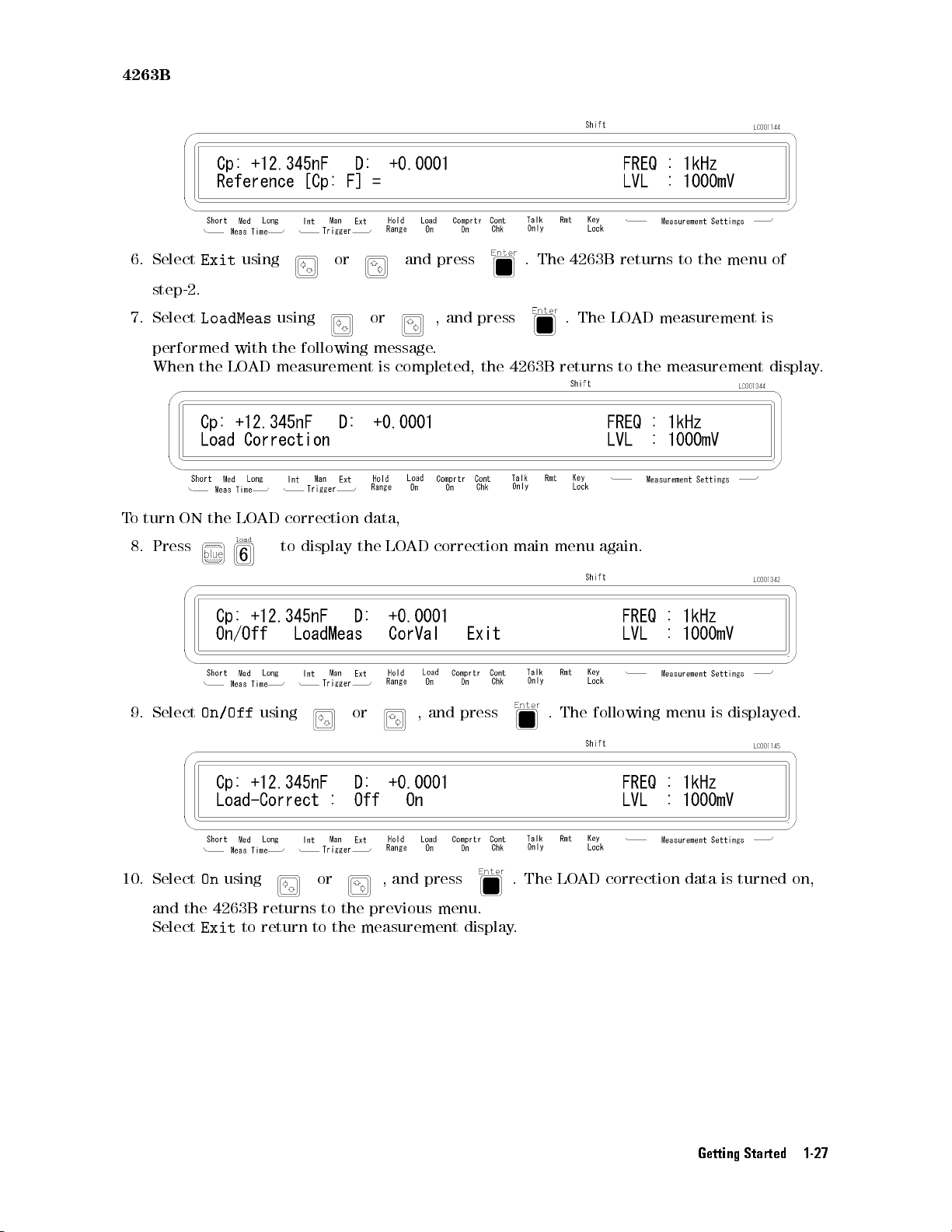
4263B
6.
Select
step-2.
7.
Select
performed
When
T
o
turn
8.
Press
Exit
LoadMeas
the
ON
the
with
LO
LO
using
using
the
following
AD
measurement is
AD
correction
to
display
or and
or ,
message.
completed, the
data,
the
LO
AD
press
and
press
correction
.
The
4263B
.
The
4263B returns
main
menu
returns
LO
AD
to
again.
to
the
measurement
the
measurement
menu
of
is
display
.
9. Select
10. Select
On/Off
On
using
using
or ,and
or , and press . The LO
and the 4263B returns to the previous menu.
Select
Exit
to return to the measurement display
press
. The
following menu
is
displayed.
AD correction data is turned on,
.
Getting Started 1-27
Page 60
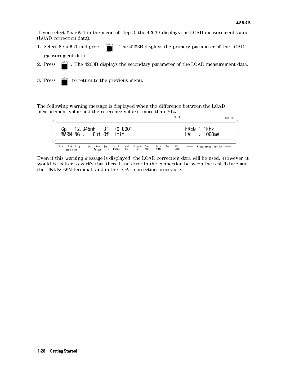
If
you select
(LO
AD correction
1.
Select
MeasVal
MeasVal
measurement data.
data).
and
in
press
the
menu
of
step-3,
.
The 4263B
the
displays
4263B
displays
the
primary
the
LO
AD
measurement
parameter
of
the
4263B
value
LO
AD
2.
Press
3.
Press
The
following
measurement
Even
if this
would
the
be better
UNKNOWN terminal,
.
to
warning
value
warning
The
return
to
4263B
message
and
message
verify
displays
to
the
the
reference
that
and
previous
is
displayed
is
displayed,
there
in
the
the
secondary
value
is
no
LO
AD
menu.
when
is
more
the
LO
error
correction
parameter
the
than 20%.
AD
in
the
dierence
correction
connection
procedure
of
the
between
data
between
.
LOAD
will
measurement data.
the
LO
AD
be
used.
the
test
However
xture
,
and
it
1-28 Getting Started
Page 61
2
Operating
This chapter
This chapter
provides
includes
the 4263B
step-by-step
the
Measurement Conguration
Triggering
Applying
Using
Display
Locking
Returning the
Saving
Printing
T
esting
If
Y
ou
Refer
to
a
Measurement
the
DC
the
Comparator
Conguration
Out
the
Local
and
Recalling
Measurement
the
4263B
Have
a
Problem
Chapter
3
Bias
Front
Mode
Instrument
for
the
following
P
anel
keys
(Exiting
Data
description
instructions
sections:
the
Remote
Settings
of
each
for
Mode)
front
using
panel
the
key's
4263B
function.
LCR
Meter
.
Measurement
This
section
measurement
Selecting
discusses
functions
Measurement
Conguration
the
4263B
.
Time Mode
To select measurement time mode
settings (Short, Med or Long).
Setting the A
veraging Rate
To set the averaging time:
1. Press .
's
general
, press
conguration
. The annunciator(
topics
that
apply
to many
9
) displays the current
Operating the 4263B 2-1
or all
Page 62
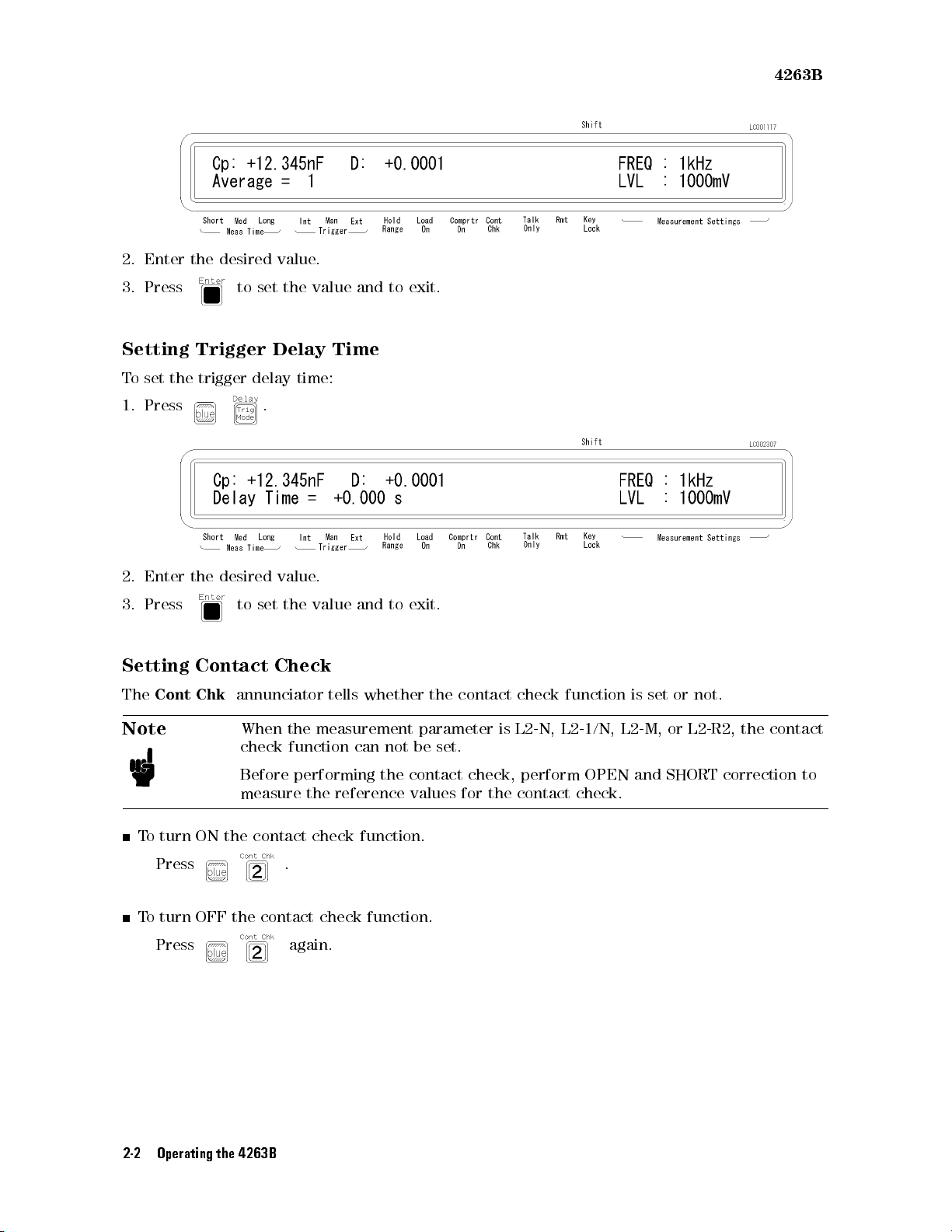
2.
Enter
the
3.
Press to
desired
set
value
the
.
value
and
to
4263B
exit.
Setting
T
o
set
the
1.
Press
2.
Enter
3.
Press
Setting
The
Cont
Note
Trigger
trigger
the
desired
to
Contact
Chk
annunciator
When the
check
Before
measure
Delay
delay
.
value
set
Check
Time
time:
.
the
value
and
to
exit.
tells
whether the
measurement parameter
function
performing
the
can
not
the
reference
be
contact
values
contact check
is L2-N,
set.
check,
for
the
perform
contact
function
L2-1/N,
OPEN
check.
is
set
L2-M,
and
or
not.
or
L2-R2,
SHORT
the
contact
correction
to
T
o turn
Press
ON
the
contact
.
check
function.
To turn OFF the contact check function.
Press
again.
2-2 Operating the 4263B
Page 63
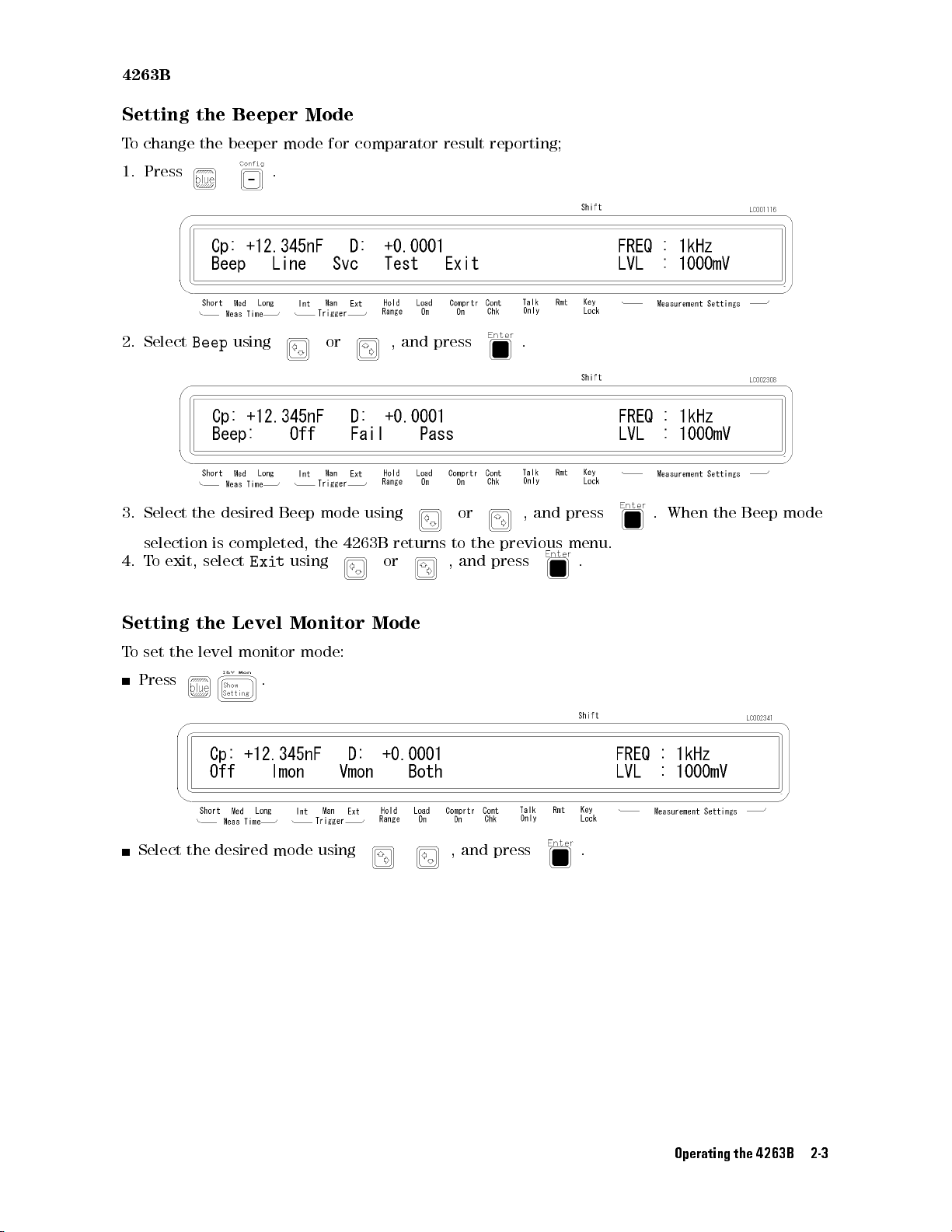
4263B
Setting
T
o
change
1.
Press
2.
Select
3.
Select
selection
4.
T
o
exit,
the
the
Beep
the
is
select
desired
Beeper
beeper
mode
.
using
Beep
completed,
Exit
using
Mode
for
or ,
mode
the
comparator
and
using
4263B
returns
or ,
result
press
or ,
to
and
reporting;
the
previous
press
.
and
press
menu.
.
.
When
the
Beep
mode
Setting
T
o
set the
Press
the
Level Monitor
level
monitor
.
Mode
mode:
Select the desired mode using , and press .
Operating the 4263B 2-3
Page 64
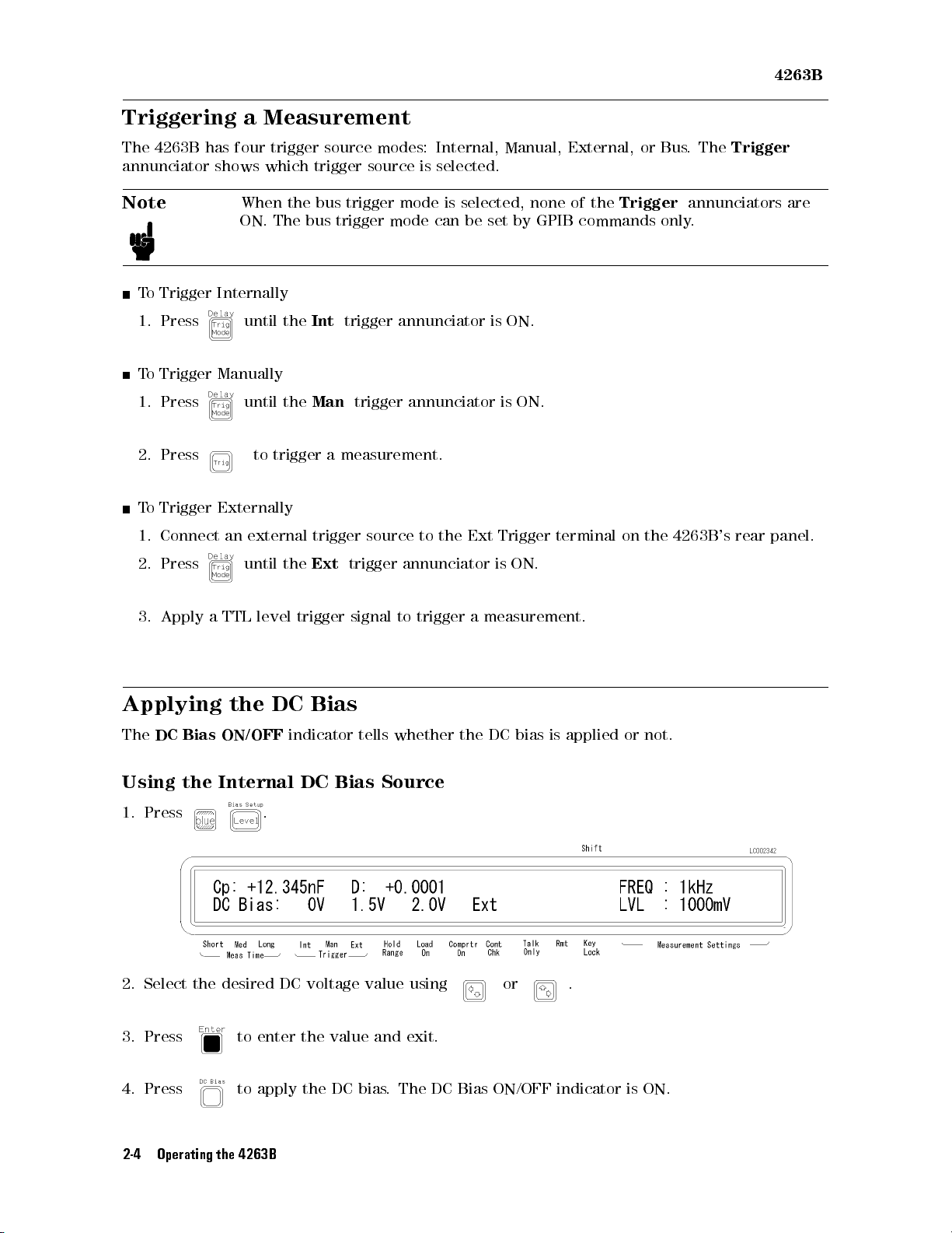
4263B
Triggering a
The
4263B
annunciator
Note
has
shows
four
When the
ON.
T
o
Trigger
1.
Press
T
o
Trigger
1.
Press
2.
Press to
To
Trigger Externally
1.
Connect
2.
Press
Internally
until
Manually
until
an
until
Measurement
trigger source
which
trigger
bus trigger
The
bus
trigger
the
Int
trigger
the
Man
trigger
trigger
external
the
a
measurement.
trigger
Ext
trigger
modes: Internal,
source is
mode
selected.
mode is
can
selected,
annunciator
annunciator
source
to
the
annunciator
Manual, External,
none
be
set
by
GPIB
is
ON.
is ON.
Ext
Trigger
is
ON.
of
the
commands
terminal
or Bus
Trigger
only
on
the
.The
Trigger
annunciators
.
4263B
's
rear
are
panel.
3.
Apply
Applying
The
DC Bias
Using
1.
Press
a
TTL
the
ON/OFF
the
Internal DC
level
DC
.
trigger
Bias
indicator
Bias Source
signal
to
trigger a
tells whether
measurement.
the DC
bias
is
2. Select the desired DC voltage value using or .
3. Press
to enter the value and exit.
applied
or
not.
4. Press to apply the DC bias. The DC Bias ON/OFF indicator is ON.
2-4 Operating the 4263B
Page 65
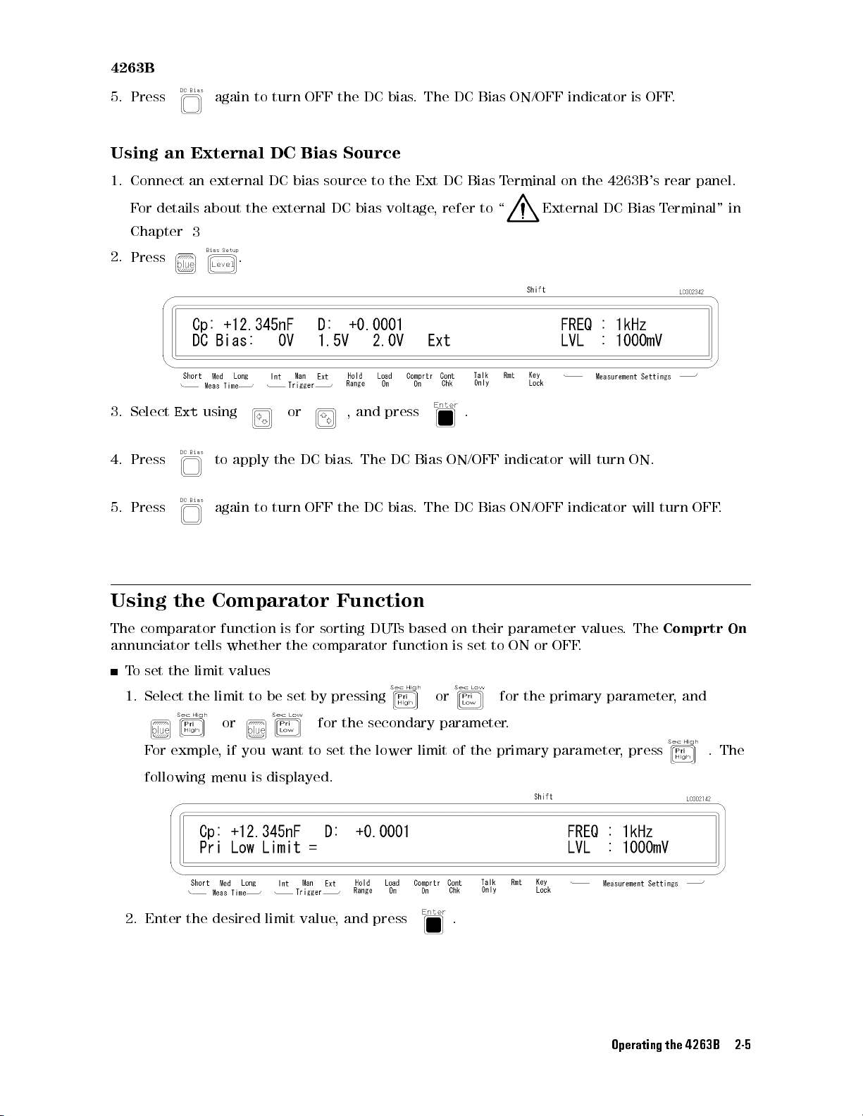
4263B
5.
Press
Using an
1.
Connect
F
or
Chapter
2.
Press .
3.
Select
External DC
an
details
3
Ext
4. Press
again
external
about
using
to apply
to turn
DC
the
external
OFF the
Bias
bias
or ,
the DC
Source
source
DC
bias.
DC bias
to
bias
voltage
and
press
The DC
the
. The
Ext
,
Bias
DC
Bias
DC Bias
refer
to
.
ON/OFF
ON/OFF
Terminal
\
External
indicator
indicator
on the
will
turn
is
4263B's
DC
Bias
ON.
OFF
.
rear panel.
T
erminal"
in
5.
Press
Using
The comparator
annunciator tells
To
set the
1. Select
again
the
Comparator
function
whether the
limit
values
the limit
to
to
or for
F
or
exmple
,
if
you
following menu is displayed.
turn
is
be
want
OFF
for
sorting
comparator
set
by
to
set the
the
DC bias
Function
DUT
s
function
pressing
the
secondary
lower
. The
DC Bias
based
on
is
their
set
or for the
parameter
limit
of
the
ON/OFF
parameter
to
ON
.
primary
or
indicator
values
OFF
.
.
will
The
primary parameter
parameter
,
press
turn
OFF
Comprtr
,
and
.
.
On
The
2. Enter the desired limit value, and press .
Operating the 4263B 2-5
Page 66
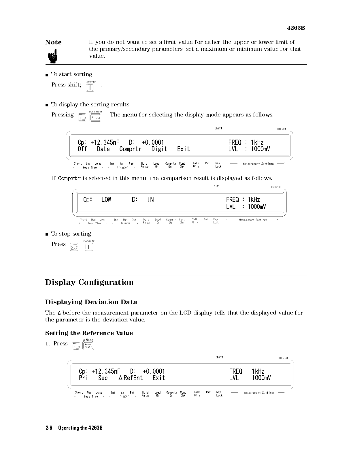
Note
T
o start
Press
To
shift;
display
sorting
the
If
you
do
not
the
primary/secondary
value
.
.
sorting
results
want
to
set
parameters
a
limit
value
,
set
for
either the
a
maximum
upper or
or minimum
lower limit
value for
4263B
of
that
Pressing
If
Comprtr
T
o
stop
Press
is
sorting:
.
selected
.
The
in
menu
this
for
menu,
selecting
the
comparison
the
display
result
mode
is
appears
displayed
as
as
follows
follows
.
.
Display
Displaying Deviation
The
1
Conguration
before
the
measurement
Data
parameter
the parameter is the deviation value
Setting
1. Press
the Reference V
.
alue
2-6 Operating the 4263B
on
the
LCD display
tells
that
the
displayed
value
for
.
Page 67
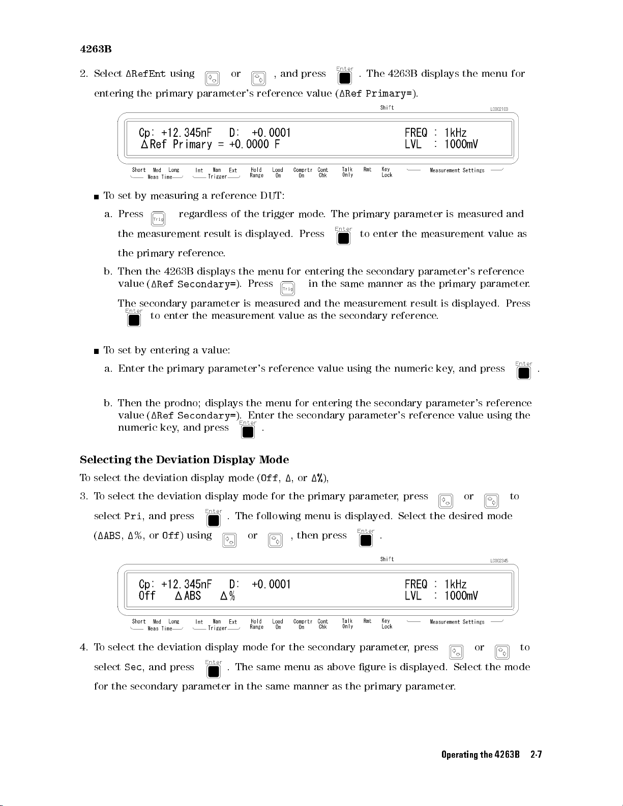
4263B
2.
Select
entering the
T
o
a.
b.
T
o
a.
1RefEnt
set
by
measuring
Press
the
measurement
the
primary
Then
the
value
(
1Ref
The
secondary
to
set by
Enter
entering a
the
using
or ,
primary parameter's
a
reference
regardless
reference
4263B
displays
Secondary=
parameter
enter
the
of
the
result
is
displayed.
.
the menu
).
is
measurement
value:
primary
parameter's
and press
reference value
DUT:
trigger
mode
Press
for entering
Press
measured
and
value
reference
in
as
(
1Ref
.
The
the
the
same
the
measurement
the
secondary
value
using
.
The 4263B
Primary=
displays the
).
primary parameter
to
enter
the
measurement
secondary
manner
parameter's
as
the
result
reference
the
numeric
is measured
primary
is
displayed.
.
key
,
and
menu for
and
value
reference
parameter
Press
press
as
.
.
b.
Then
the
prodno;
value
(
1Ref
numeric
Selecting the
T
o
select
3.
4. T
the
T
o
select
select
Pri
(
1ABS
,
1
o select the deviation display mode for the secondary parameter
select
Sec
key
Deviation
deviation
the
deviation
,
and
%,
or
Off
, and press
press
displays
Secondary=
,
and
press
Display
display
display
) using
the
menu
for
).
Enter
the
secondary
entering the
secondary
parameter's
reference value
.
Mode
mode
(
Off
,
1
,
or
1%
),
mode
for
the
.
The
following
or ,
primary
menu
then press
parameter
is
displayed.
.
,
press
Select
, press
. The same menu as above gure is displayed. Select the mode
for the secondary parameter in the same manner as the primary parameter.
parameter's
or to
the
desired
or to
reference
using
the
mode
Operating the 4263B 2-7
Page 68
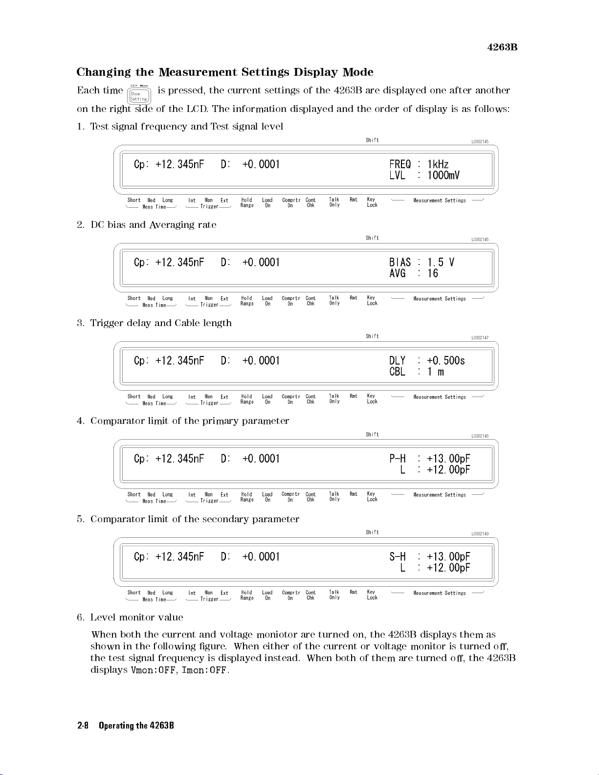
4263B
Changing
Each
time is
on
the
right
1.
T
est
signal
2.
DC
bias
3.
Trigger
the
side
frequency
and
A
delay
Measurement
pressed,
of
the LCD
veraging
and
Cable
the
.The
and T
rate
length
est signal
Settings
current
settings
Display
of
information displayed
level
the
Mode
4263B
and the
are
displayed
order of
one after
display is
another
as follows:
4.
Comparator
5.
Comparator limit
limit
of the
of the
primary parameter
secondary parameter
6. Level monitor value
When both the current and voltage moniotor are turned on, the 4263B displays them as
shown in the following gure. When either of the current or voltage monitor is turned o,
the test signal frequency is displayed instead. When both of them are turned o, the 4263B
displays
Vmon:OFF,Imon:OFF
.
2-8 Operating the 4263B
Page 69
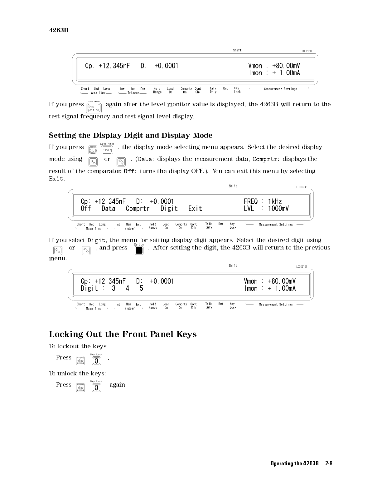
4263B
If
you
press
test
signal
frequency
Setting the
If you
mode
result
Exit
If
you
press
using
of
.
select
the
or ,
menu.
again
and
Display
or .
comparator
Digit
,
the
and
press
after
test
Digit
,the
,
Off
menu
the
level
signal
and
display
(
Data
:
:
turns
for setting
.
After
monitor
level
display.
Display
mode
displays
the
display
display
setting
value
Mode
selecting
the
measurement
OFF
digit
the
is
menu
.).
Y
appears
digit,
displayed,
appears
data,
ou
can
exit
.
Select
the
4263B
the 4263B
.
Select
Comprtr
this
the
will
will return
the
desired
:
displays
menu by
desired
return to
display
the
selecting
digit
using
the
previous
to the
Locking
Out
To lockout the keys:
Press
To unlock the keys:
Press
the
.
again.
Front
P
anel
K
eys
Operating the 4263B 2-9
Page 70
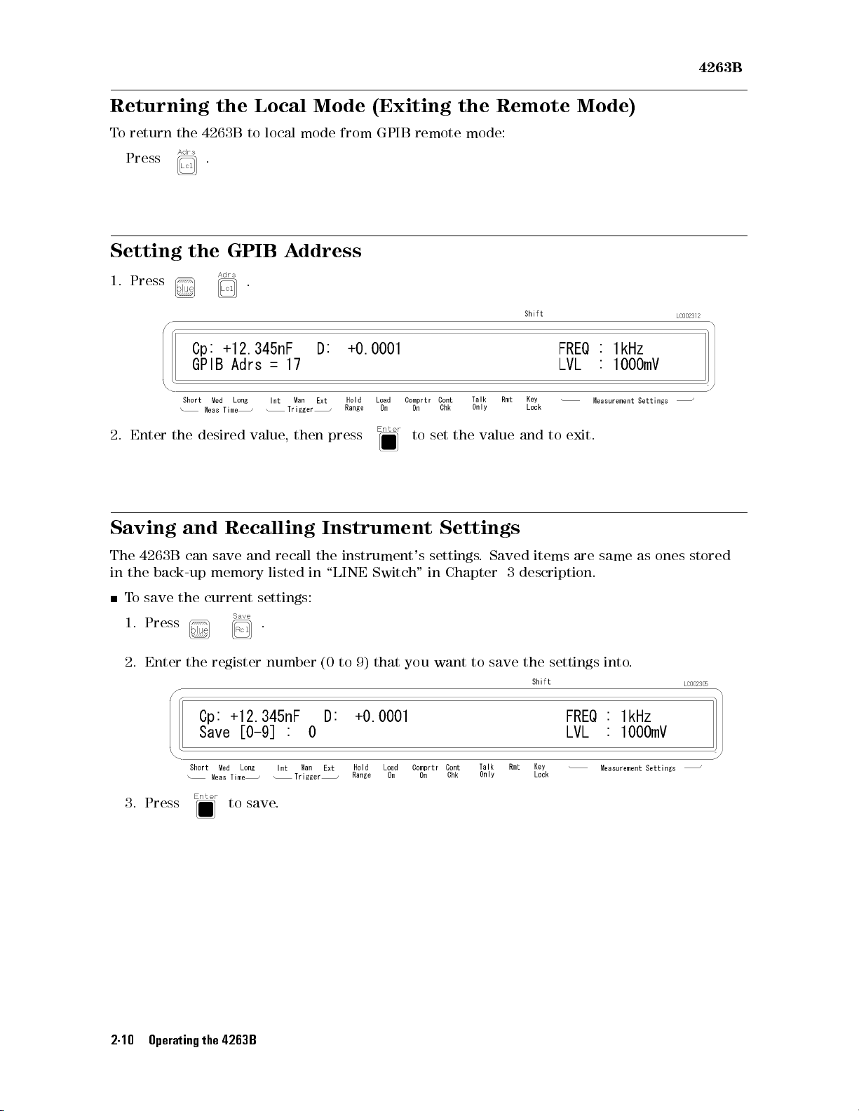
4263B
Returning the
T
o
return
Press
Setting
1.
Press
2.
Enter the
the
the
4263B to
.
GPIB
desired
Local Mode
local mode
A
ddress
.
value
,
then
press
(Exiting the
from GPIB
to
remote mode:
set the
value
Remote Mode)
and
to
exit.
Saving
The
4263B
in
the
T
o
1.
2.
back-up
save
Press
Enter
and
can
the
the
Recalling
save
memory
current
register
3. Press to save
and
recall
listed
settings:
.
number
.
Instrument
the
instrument's
in
\LINE
(0
to
Switch
9)
that
Settings
settings
"
in Chapter
you
want
.
to
Saved
3
description.
save
the
items
settings
are
same
into
as
ones
stored
.
2-10 Operating the 4263B
Page 71
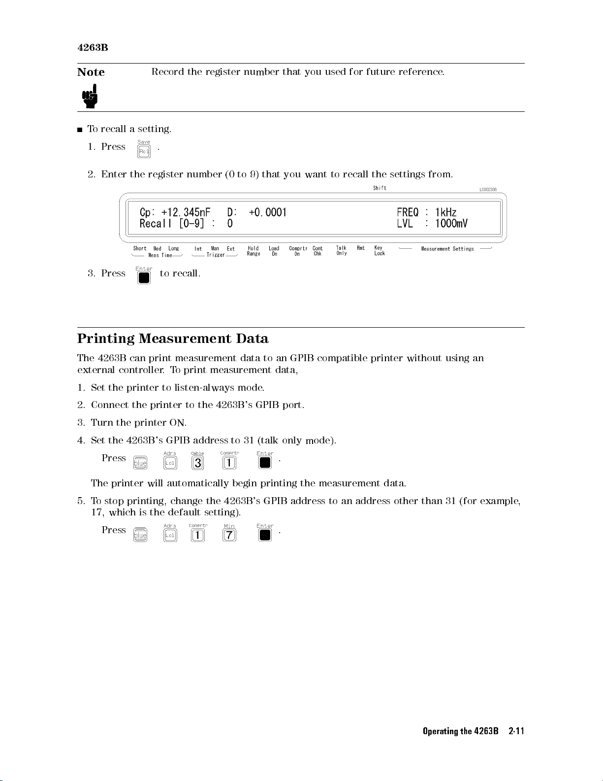
4263B
Note
To
recall a
1.
Press
2.
Enter the
3.
Press
Printing
Record
the
register
setting.
.
register number
to
recall.
Measurement
(0
to
Data
number
9)
that
that
you
you
want
used
to
for
recall
future
the
reference
settings
.
from.
The
4263B
external
1.
Set
2.
Connect
3.
Turn
4.
Set
Press
The
5.
To
stop
17,
Press
can
controller
the
printer
the
the
printer
the
4263B
printer
printing,
which
print
.
to
printer
's
GPIB address
will
automatically
is
the
measurement
T
o
print
measurement
listen-always
to
the 4263B
ON.
change
default
the
setting).
data
mode
to 31
begin
4263B
's
GPIB
(talk
's
to
an
data,
.
port.
only
.
printing
GPIB
.
GPIB
mode).
the
address
compatible
measurement
to
an
address
printer
data.
other
without using
than
31
(for
an
example
,
Operating the 4263B 2-11
Page 72
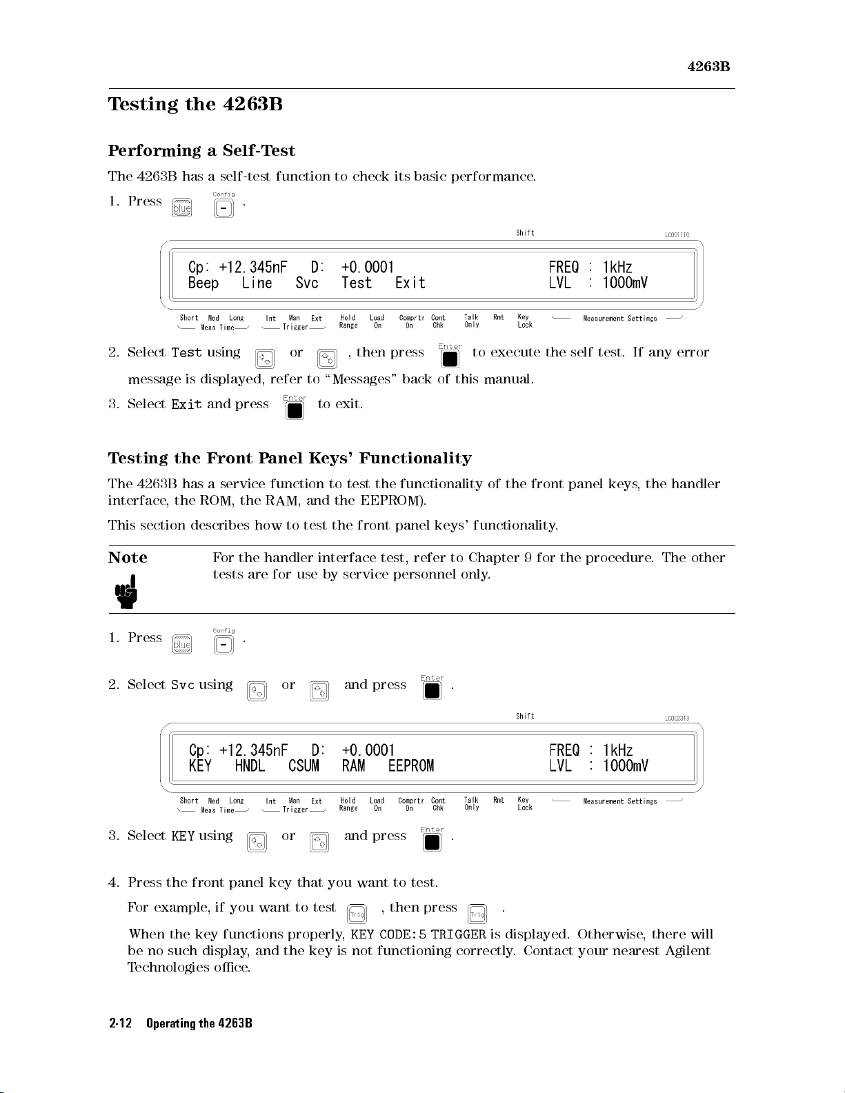
4263B
Testing
P
erforming
The
4263B
1.
Press
2.
Select
Test
message
3.
Select
T
esting the
The
interface
Exit
4263B has
,
the 4263B
a Self-T
has a
self-test function
.
using
is
displayed,
and
press
Front P
a service
the
ROM, the
est
or ,
refer
anel
function
RAM,
to check
to
\Messages"
to
exit.
K
eys'
to
test
and
the
then
its basic
press
back
performance.
of
Functionality
the
functionality
EEPROM).
this
to
execute
manual.
of
the
the
front
self
panel
test.
keys
If
,
any
the
error
handler
This
section
Note
1.
Press
2.
Select
3. Select
describes
Svc
KEY
F
or
tests
using
using
the
are
.
how
to
test
the
front
handler
for
interface
use
by
service
or and
test,
press
or and press .
panel
refer
personnel
4. Press the front panel key that you want to test.
For example, if you want to test
, then press .
keys'
to
only
.
functionality
Chapter
9
.
for
.
the
procedure
.
The
other
When the key functions properly,
KEY CODE:5 TRIGGER
is displayed. Otherwise, there will
be no such display, and the key is not functioning correctly. Contact your nearest Agilent
Technologies oce.
2-12 Operating the 4263B
Page 73

4263B
5. T
6.
o exit
Select
the front
Exit
and
panel key
press
test, press
to
exit.
twice.
Operating the 4263B 2-13
Page 74
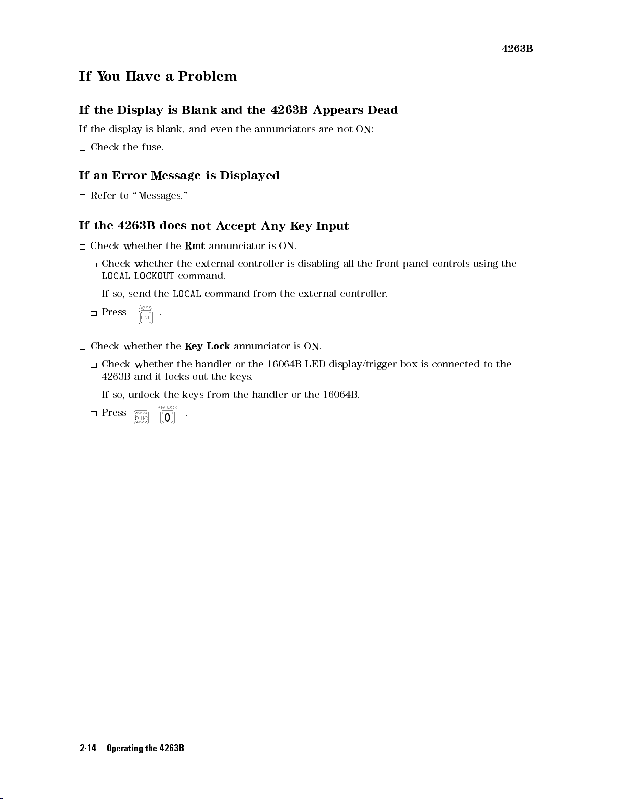
If Y
ou Have
If
the
If
the
Display is
display is
a Problem
Blank and
blank, and
even the
the 4263B
annunciators are
4263B
Appears Dead
not ON:
If
If
Check
an
Refer
the
Check
Check
LOCAL
If
Press
Check
Check
4263B
If
Press
the
Error
to
\Messages
4263B
whether
whether
LOCKOUT
so
,
send
whether
whether
and
so
,
unlock
fuse
.
Message
does
the
the
LOCAL
.
the
it
locks
the
is
."
not
A
Rmt
annunciator
the
external
command.
command
K
ey
Lock
the
handler
out
the
keys
from
.
Displayed
ccept
Any
is
controller
from
annunciator
or
the
16064B
keys
.
the
handler
K
ON.
is
the
or
ey
Input
disabling
external
is
ON.
LED
the
all
the
front-panel
controller
display/trigger
16064B
.
controls
using the
.
box
is
connected
to
the
2-14 Operating the 4263B
Page 75
3
Function
This chapter
Front
Rear
T
echnical
provides information
P
anel
P
anel
Information
Reference and
on
all
of
the
Technical
4263B
's
functions
Information
.
Function Reference and Technical Information 3-1
Page 76
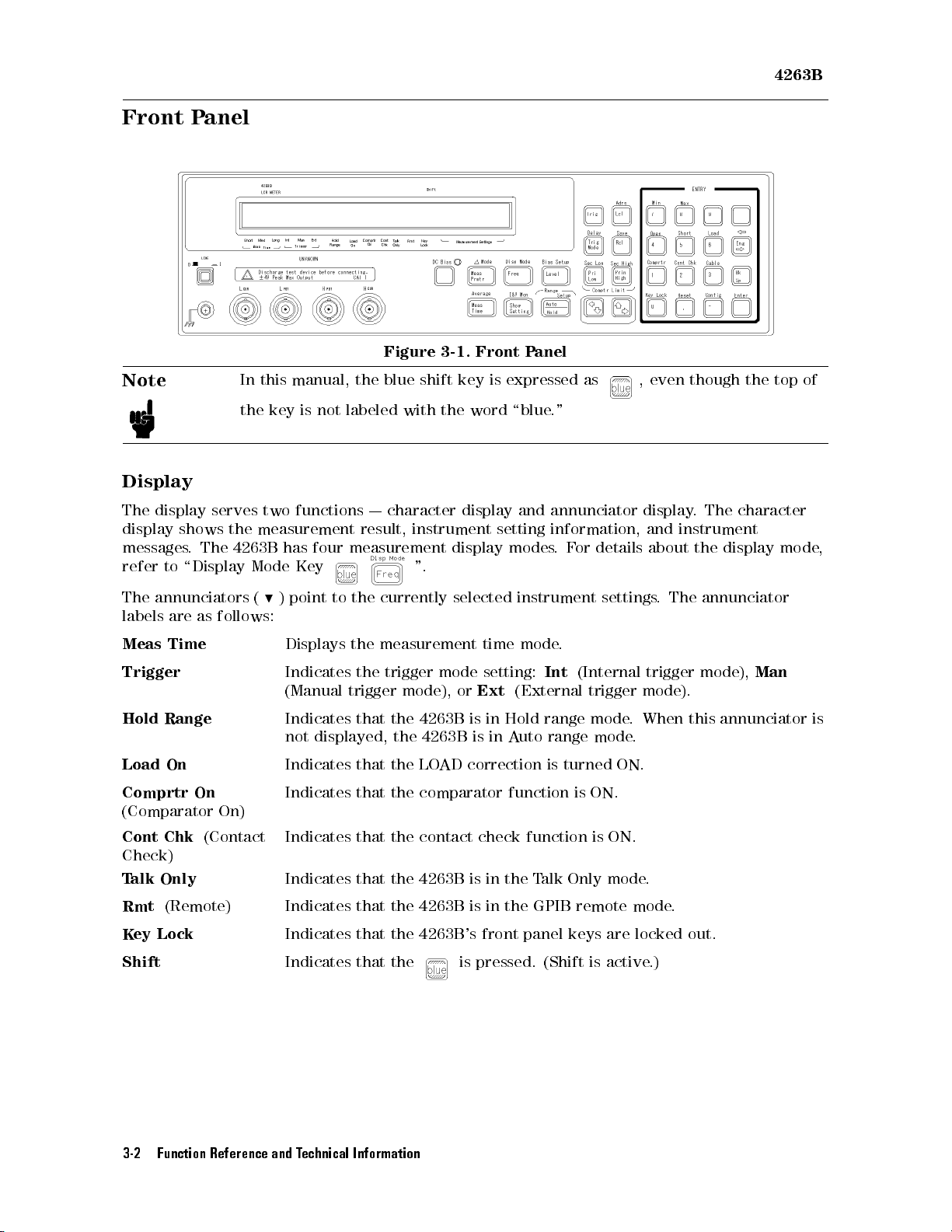
4263B
Front P
Note
Display
The
display serves
display
messages
refer
shows the
.
to
\Display
anel
The
In
this
manual, the
the
key is
two functions
measurement
4263B
has
Mode
not labeled
four
Key
Figure 3-1.
blue shift
with
|
character
result,
instrument
measurement
".
key is
the
word
display
display
Front P
expressed
\blue
and
setting
modes
anel
as
."
annunciator
information,
.
F
or
details
,
even
display
and
about
though the
.
The
character
instrument
the
display
top of
mode,
The
annunciators
labels
are
as
Meas
Time
Trigger
Hold
Range
Load
On
Comprtr
On
(Comparator
Cont
Chk
(Contact
(
follows:
On)
9
)
point
Displays
Indicates
(Manual
Indicates
not
Indicates
Indicates
Indicates
to
the
currently
the
measurement
the
trigger
trigger
that
mode),
the
displayed, the
that the
that the
that
the
selected
mode
or
4263B
4263B is
LOAD
is
correction
time
setting:
Ext
in Hold
in A
instrument
mode
Int
(External
range mode
uto
range
is
comparator function
contact
check
function is
.
turned
Check)
Talk Only
Rmt
(Remote) Indicates that the 4263B is in the GPIB remote mode
Key Lock
Shift
Indicates that the 4263B is in the T
alk Only mode
Indicates that the 4263B's front panel keys are locked out.
Indicates that the
is pressed. (Shift is active
settings
(Internal
trigger
mode
ON.
is ON.
ON.
.
The
trigger
mode).
.When
.
.
.
.)
annunciator
mode),
Man
this annunciator
is
3-2 Function Reference and Technical Information
Page 77
4263B
LINE
The
Switch
LINE
operating
and
no
operating
The
4263B
The
following
T
est
signal
T
est
signal
DC
bias
DC
bias
Measurement
Deviation
Measurement
Measurement
Measurement
A
veraging
Cable
length
Trigger
Trigger
Contact
Comparator
Comparator
Level
monitor
Display
Display
Switch
voltages
turns
are
voltages
's
settings
settings
frequency
level
source
voltage
selection
setup
parameters
measurement
range
range
time
rate
mode
delay
check
function
function
limit
setting
mode
digits
setting
applied
are
are
mode
value
the
4263B
are
held
backed
(internal
mode
-
ON/OFF
ON/OFF
ON
to
the
instrument. In
applied
in backup
up:
or
Auto
or Hold
state
state
or
OFF
.
to the
instrument.
memory for
external)
In the
1(ON) position,
the 0(OFF)
about 72
position, no
hours after
power is
power is
applied and
power is
turned OFF
all
applied
.
The
DC
bias
.
to
has
The
the
ON/OFF
OFF
data
beeper
Note
Note
Chassis T
bias
The
memory
data
erminal
output
4263B
and
The Chassis terminal is tied to the
state
is
not
saved.
At
power
on,
the
4263B
sets
the
.
non-volatile
saved
mode
memory
to
EEPROM
is
not
(EEPROM)
such
lost
when
in
addition
as
OPEN/SHORT/LOAD
the
power
is turned
to
the
o.
backup
correction
instrument's chassis and can be used for measurements that
require guarding.
UNKNOWN T
erminals
These are the terminals used to connect a four-terminal-pair test xture or test leads for
measuring DUT
Caution
s. The connector type is BNC.
Do
not
apply DC voltage or current to the UNKNOWN terminals. Doing so will
damage the 4263B. Before you measure a capacitor, be sure the capacitor is
fully discharged.
DC
Function Reference and Technical Information 3-3
Page 78
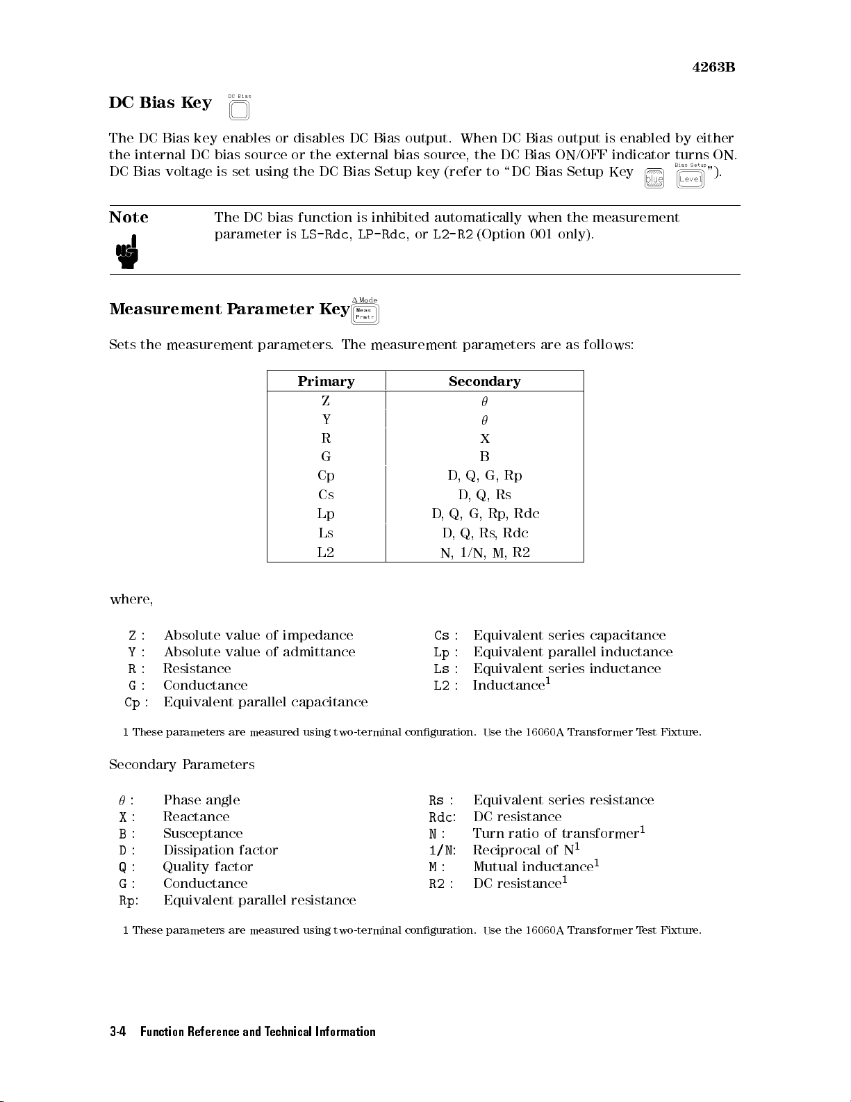
DC
The
the
internal
DC
Bias
Note
Bias
DC
K
ey
Bias
key
DC
voltage
enables
bias
source
is
set
using the
The
DC
bias
parameter
or disables
or the
DC Bias
function is
is
LS-Rdc
DC Bias
external bias
output. When
source,
Setup key
inhibited automatically
,
LP-Rdc
,or
L2-R2
the DC
(refer to
(Option
DC Bias
Bias ON/OFF
\DC Bias
when the
001 only).
output is
Setup Key
measurement
4263B
enabled by
either
indicator turns
ON.
").
Measurement
Sets
the
measurement
where
,
Z
:
Absolute value
Y
:
Absolute value
R
:
Resistance
G
:
Conductance
Cp
:
Equivalent parallel
P
arameter
parameters
of impedance
of admittance
K
ey
.
The
measurement
parameters
Primary Secondary
Z
Y
R X
G B
Cp D
Cs D
Lp D
Ls D
L2 N,
,
Q,
G,
,
Q,
Rs
,
Q,
G,
Rp
,
Q,
Rs
,
1/N,
M,
Cs
:
Equivalent series
Lp
:
Equivalent parallel
Ls
:
Equivalent series
L2
:
Inductance
capacitance
Rp
,
Rdc
Rdc
R2
are as
1
follows:
capacitance
inductance
inductance
1
These
parameters
Secondary P
: Phase angle
X
: Reactance
B
: Susceptance
D
:
Dissipation factor
Q
: Quality
G
: Conductance
Rp
: Equivalent parallel resistance
1
These parameters are measured using two-terminal conguration. Use the 16060A Transformer Test Fixture.
are
arameters
factor
measured
using
two-terminal
conguration.
Rs
Rdc
N
1/N
M
R2
Use
the
16060A Transformer
: Equivalent series resistance
: DC resistance
: Turn ratio of transformer
:
Reciprocal of N
: Mutual
inductance
: DC resistance
Test
1
1
1
1
3-4 Function Reference and Technical Information
Fixture.
Page 79
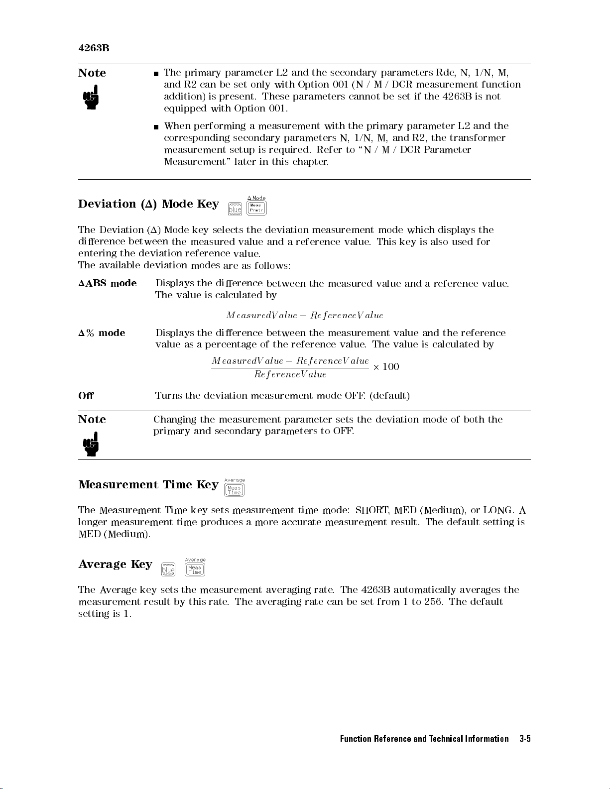
4263B
Note
The
primary
and
R2
addition)
equipped
can
is
with
parameter
be
set
only
present.
Option
L2
with
These
001.
and
the
secondary
Option 001
parameters
(N /
cannot
parameters
M/
DCR measurement
be
set if
the 4263B
Rdc
,
N,
1/N, M,
function
is not
Deviation (1)
The
Deviation (1)
dierence
entering
The
available
1ABS
1%
mode
the
mode
between
deviation
deviation
O
When
performing
corresponding
measurement
Measurement"
Mode K
ey
Mode key
the
measured
reference
modes
Displays the
The
value
is
Displays
value
Turns
the
as
a
percentage
the
deviation
a
measurement with
secondary
setup
is
later
in
selects
the
value
value
.
are
as
follows:
dierence
calculated by
M
easur
dierence
of
M
easur
edV
R
ef
measurement
parameters
required.
this
chapter
deviation
and
a
between
edV
al
ue
between
the
reference
al
ue
0
er
enceV
Refer
.
measurement
reference
the
measured
0
R
ef
er
the
measurement
R
ef
er
enceV
al
ue
mode
the primary
N,
1/N,
to
\N
value
.
enceV
al
value
. The
al
ue
2
OFF
.
(default)
M,
/M
mode
This
value
ue
100
parameter L2
and
R2, the
/DCR
Parameter
which
key
is
also
and
a
value
and
value is
calculated
transformer
displays
used
reference
the
reference
and the
the
for
value
by
.
Note
Measurement
The
Measurement
longer
MED
measurement
(Medium).
Average K
The A
verage
Changing
primary
Time
Time
and
K
key
time
ey
key sets the measurement averaging rate
measurement result by this
setting is 1.
the
measurement
secondary
parameter
parameters
to
sets
OFF
the
.
deviation
mode
of
both
ey
sets
measurement
produces
a more
time mode:
SHORT,
accurate measurement
MED (Medium),
result. The
default setting
or LONG.
. The 4263B automatically averages the
rate. The averaging rate can be set from 1 to 256. The default
the
A
is
Function Reference and Technical Information 3-5
Page 80
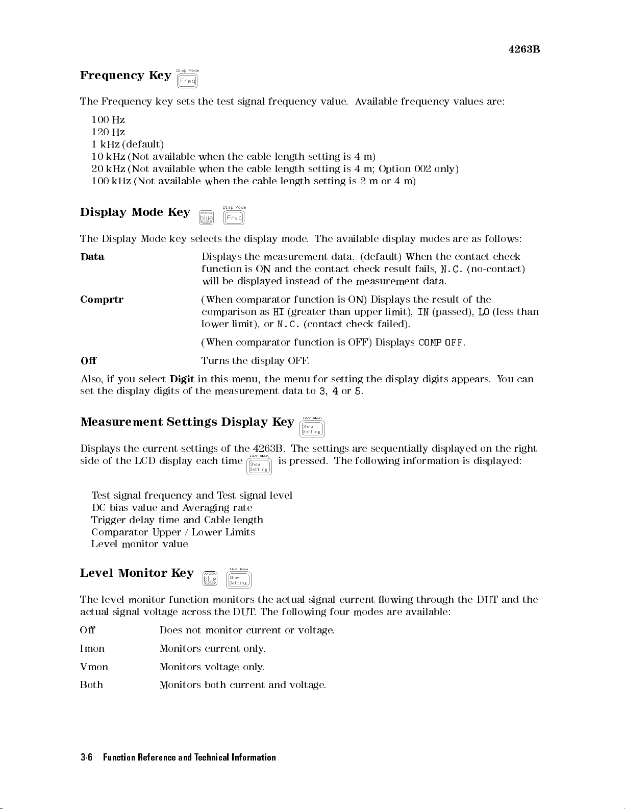
4263B
Frequency
The
Frequency
100
Hz
120
Hz
1
kHz
10
kHz
20
kHz
100
kHz
K
(default)
(Not
available
(Not
available
(Not
key
Display Mode
The
Display Mode
Data
Comprtr
O
ey
sets
available
Key
key
selects
the
test signal
when
when
when
the
Displays
function
will
be
the cable
the cable
the cable
displayed
frequency value
display
the
measurement
is
ON
and
(When comparator
comparison
lower limit),
as
HI
or
(When comparator
Turns
the
display
length setting
length setting
length setting
mode
.
The
data.
the
contact
instead
of
function
(greater
N.C.
than upper
(contact
function
OFF
.
.A
vailable frequency
is 4
m)
is 4
m; Option
is 2
mor
available
display
(default)
the
is
check
ON)
result
measurement
Displays
limit),
check
failed).
is
OFF)
Displays
4
m)
002
modes
When
fails
data.
the
IN
COMP
values are:
only)
are
the
contact
,
N.C.
result
of
(passed),
OFF
.
as
follows:
check
(no-contact)
the
LO
(less
than
Also,
if
you
select
Digit
in
this
set
the
display
Measurement
Displays
side
of
the
T
est
signal frequency
DC
bias
Trigger
digits
Settings Display
the current
LCD
display
value and
delay
time and
Comparator Upper
Level
monitor
value
Level Monitor K
of
the
measurement
settings
each
and T
Averaging
Cable length
/ Lower
ey
menu,
of
the
time
est signal
rate
Limits
the
K
4263B
level
menu
data
ey
.
The
is
pressed.
for
to
3
,
settings
setting
4
or
5
are
The
the
display
.
sequentially
following
digits
displayed
information
appears
on
is
displayed:
.
Y
ou
the
can
right
The level monitor function monitors the actual signal current owing through the DUT and the
actual signal voltage across the DUT
O Does not
monitor current or voltage
Imon Monitors current only
. The following four modes are available:
.
.
Vmon Monitors voltage only.
Both Monitors both current and voltage.
3-6 Function Reference and Technical Information
Page 81
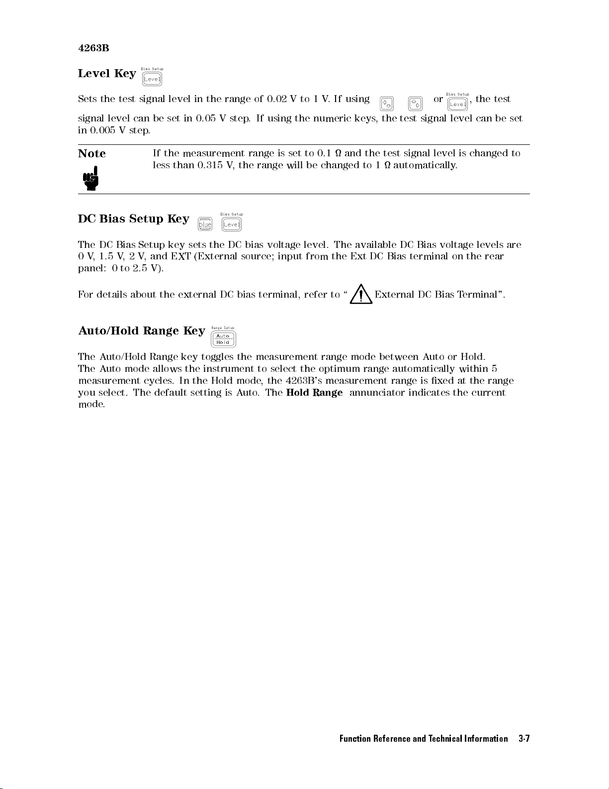
4263B
Level
Sets
signal
in 0.005
Note
the
K
test
level
Vstep
ey
signal
can
be
.
If
less
DC Bias
The
DC Bias
0
V
,
panel:
F
or
details
A
uto/Hold Range
The
A
The
A
measurement
you
select.
mode
1.5
V
,
0
to
uto/Hold
uto
mode
.
Setup K
Setup
2
V
,
and
2.5
V).
about
Range
allows
cycles
The
default
level
set in
the
measurement
than
ey
key
sets
EXT
the
external
Key
key
the
.
In
setting
in the
0.05 V
0.315
the
(External
DC
toggles
instrument
the
Hold
range of
step.
range
V
,
the
DC
bias
source;
bias
the
measurement
mode
is
A
uto
0.02 V
If using
is
range
will
voltage
input
terminal,
to
select
,
the
4263B
.
The
Hold
to 1
V.
the numeric
set
to
0.1
be
changed
level.
from
refer
range
the
optimum
's
measurement
Range
If using
keys,
and
The
available
the
Ext
to
\
mode
annunciator
the test
the
test
to
1
DC
Bias terminal
External
between
range
automatically
range
or ,
signal
signal
level
automatically
DC
Bias
voltage
DC
Bias
A
uto
or
is
xed
indicates
level
is
changed
.
on the
T
erminal".
Hold.
within
at
the
the
current
the
can
levels
rear
5
range
test
be
set
to
are
Function Reference and Technical Information 3-7
Page 82
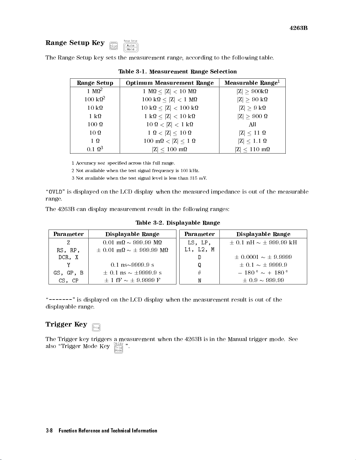
4263B
Range
The
Range
\
OVLD
"
range
.
The
4263B
Setup
Setup
Range
1
A
ccuracy
2
Not
3
Not
is
displayed
can
K
ey
key
sets
the measurement
T
able
3-1.
Optimum
1M
100
10
1
1M
100
10
1
Setup
2
2
k
k
k
100 10
10
1
0.1
not
available
available
display
3
specied
when
the
when the
on the
LCD display
measurement
100
across
this
test
signal
test signal
range,
Measurement
Measurement
j
Z
j
<
10
k
j
Z
j
<
k
j
Z
j
<
100
k
j
Z
j
<
10
<
j
Z
j
<
1
1
<
j
Z
j
10
m
<
j
Z
j
j
Z
j
100
m
full
range
.
frequency
level is
when
result in
is
100
less
than
the
the following
according to
Range
Range
M
1
M
k
k
k
1
kHz.
315
mV
.
measured
the following
Selection
Measurable
impedance
ranges:
table.
1
Range
j
Z
j
900k
j
Z
j
90
k
j
Z
j
9
k
j
Z
j
900
All
j
Z
j
11
j
Z
j
1.1
j
Z
j
110
m
is
out
of
the
measurable
T
able
3-2.
Displayable
P
P
arameter
Z
RS,
RP,
DCR,
X
Y
GS,
GP,
B
CS,
CP
\
-------
"
is
displayed
displayable range
Trigger K
ey
Displayable
0.01
6
0.01
6
6
.
0.1
0.1
1
on
m
m
fF
ns
ns
the
999.99
6
9999.9
6
6
LCD
Range
M
999.99
s
9999.9 s
9.9999 F
display
M
when
arameter
LS,
L1,
the
measurement
The Trigger key triggers a measurement when the 4263B
also \Trigger Mode Key ".
Range
Displayable
LP,
L2,
D
Q
N
M
6
0.1
6
0
result
nH
0.0001
6
0.1
180
6
0.9
is
out
6
6
of
6
+
999.99
is in the Manual trigger mode
Range
999.99
9.9999
9999.9
180
the
kH
.See
3-8 Function Reference and Technical Information
Page 83
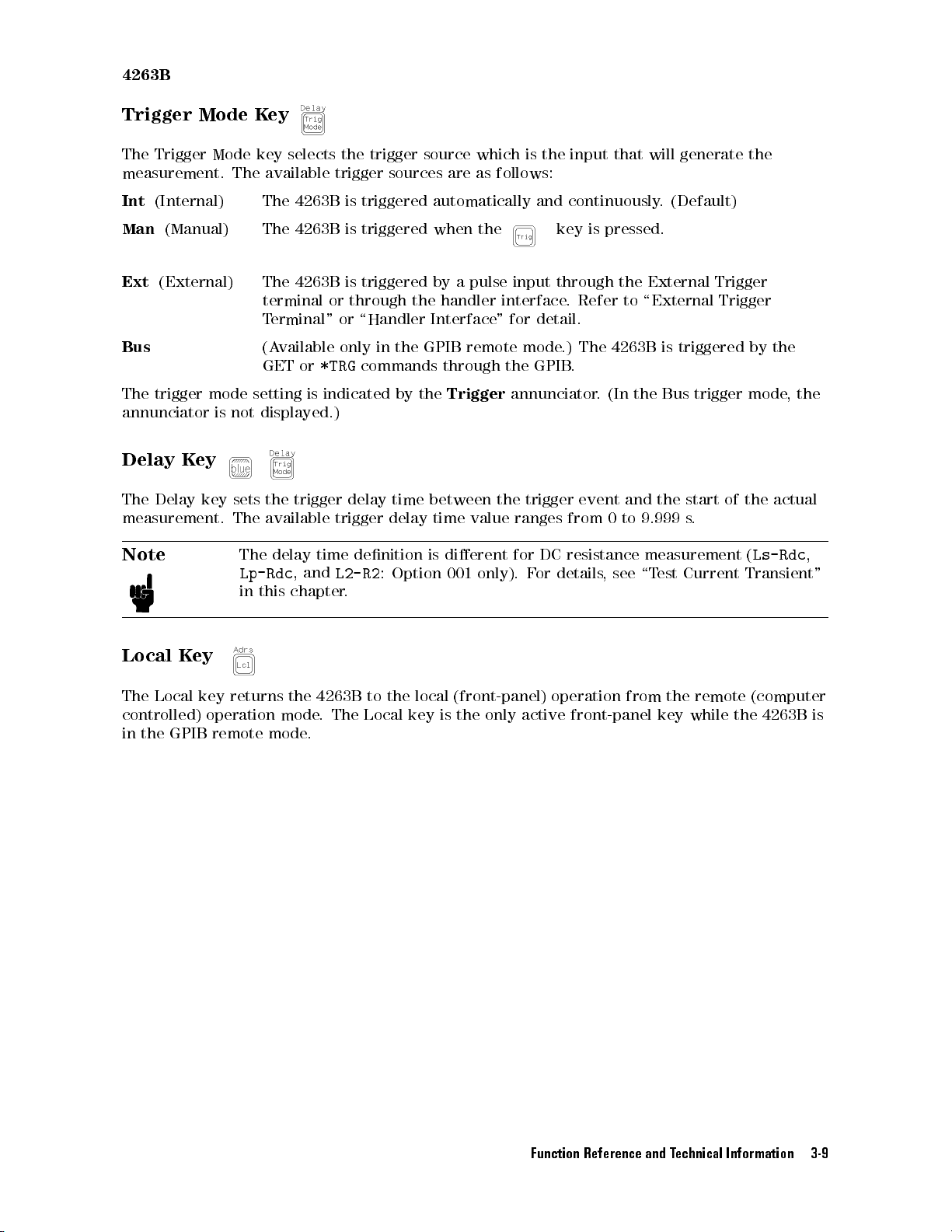
4263B
Trigger
The
Trigger
Mode
Mode
measurement.
Int
(Internal)
Man
(Manual)
Ext
(External)
Bus
The trigger
mode
annunciator is
Delay
The
K
Delay
ey
key
measurement.
Note
K
ey
key
The
available
The
The
The 4263B
terminal or
Terminal"
(A
GET or
setting
not
displayed.)
sets
the
The
available
The
Lp-Rdc
in
this
selects
4263B
4263B
vailable
is
trigger
delay
,
and
chapter
the trigger
trigger
is
triggered automatically
is
triggered when
source which
sources
is triggered
through the
or \Handler
only
in
the
GPIB
*TRG
commands
indicated
delay
trigger
time
L2-R2
by
time
delay
denition
:
Option
the
.
is the
are as
follows:
the
by
a
pulse
input
handler interface
Interface"
through
Trigger
between
time
is
dierent
001
remote
the
value
only).
for
mode
the
annunciator
trigger
ranges
for
F
input that
and continuously
key
is
pressed.
through
.
Refer
the
to
\External
detail.
.)
The
4263B
GPIB
.
.
(In
the
event
and
from
0to
9.999 s
DC
resistance
or
details
,
see \T
will generate
. (Default)
External
Trigger
Trigger
is
triggered
Bus
trigger
the
start
of the
.
measurement
est
Current
the
by
the
mode
,
the
actual
(
Ls-Rdc
,
Transient"
Local
The
K
Local
controlled)
in
the
GPIB remote
ey
key
returns
operation
the
mode
mode.
4263B
.
The
to
the
Local
local
key
is
(front-panel)
the
only
active front-panel
operation
from
the remote
key while
(computer
the 4263B
is
Function Reference and Technical Information 3-9
Page 84
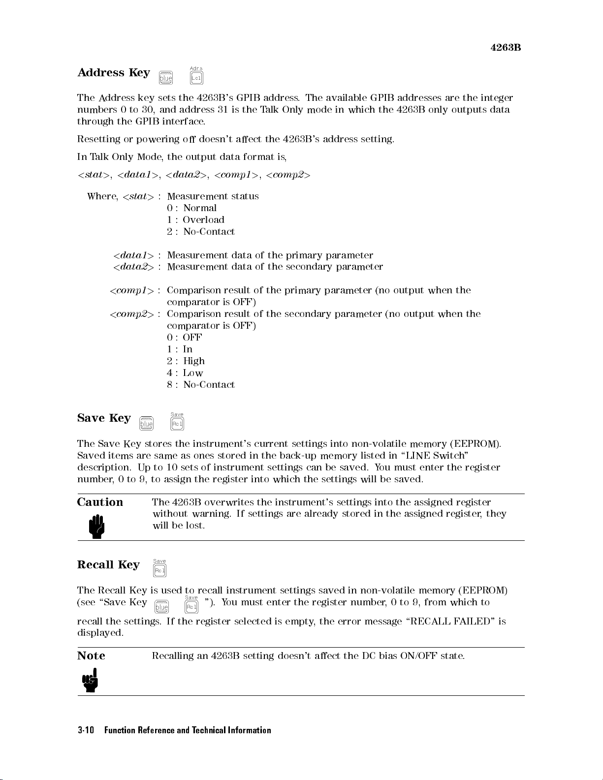
A
ddress
The
A
ddress
numbers
through
0
the
K
ey
to
GPIB
key
30,
sets
the 4263B
and
address 31
interface
.
's GPIB
is the
address.
Talk
Only mode
The available
in which
GPIB addresses
the 4263B
only outputs
are the
4263B
integer
data
Resetting
In
T
alk
<
stat
>
,
Where,
<
<
Save
K
or
Only
<
data1
<
stat
<
data1
<
data2
comp1
comp2
ey
powering
Mode
, the
>
,
<
>
:
Measurement
0:
1:
2:
>
:
Measurement
>
:
Measurement
>
:
Comparison
comparator
>
:
Comparison result
comparator
0
1
2
4
8
o
doesn't
output data
data2
>
Normal
Overload
No-Contact
:
OFF
:
In
:
High
:
Low
:
No-Contact
,
<
aect
format is
comp1
status
data
data
result
is
OFF)
is
OFF)
the
>
,
<
of
of
of
the
of the
4263B
's
address setting.
,
comp2
the
the
>
primary
secondary
primary
parameter
parameter
parameter
secondary parameter
(no
output
(no
output
when
when
the
the
The
Save
Key
Saved
items
are
description. Up
number,
0to
9, to
Caution
Recall K
ey
stores
the
same
to 10
assign
The
4263B
without
will
be
instrument's
as
ones
stored in
sets of
instrument
the
register
overwrites
warning. If
lost.
current
settings
the back-up
settings
into
which
the
instrument's
settings are
can
the
already stored
The Recall Key is used to recall instrument settings
(see \Save Key "). Y
recall the settings
. If the register
ou must enter the register number
selected is empty
displayed.
Note
Recalling an 4263B setting doesn't aect the DC bias ON/OFF state.
into non-volatile
memory listed
be
saved.
settings
settings
Y
will
into
in the
ou
memory (EEPROM).
in \LINE
must
be
saved.
the
Switch
enter
assigned
assigned register
"
the
register
register
,
they
saved in non-volatile memory (EEPROM)
,
0 to 9, from which to
, the error message \RECALL F
AILED" is
3-10 Function Reference and Technical Information
Page 85
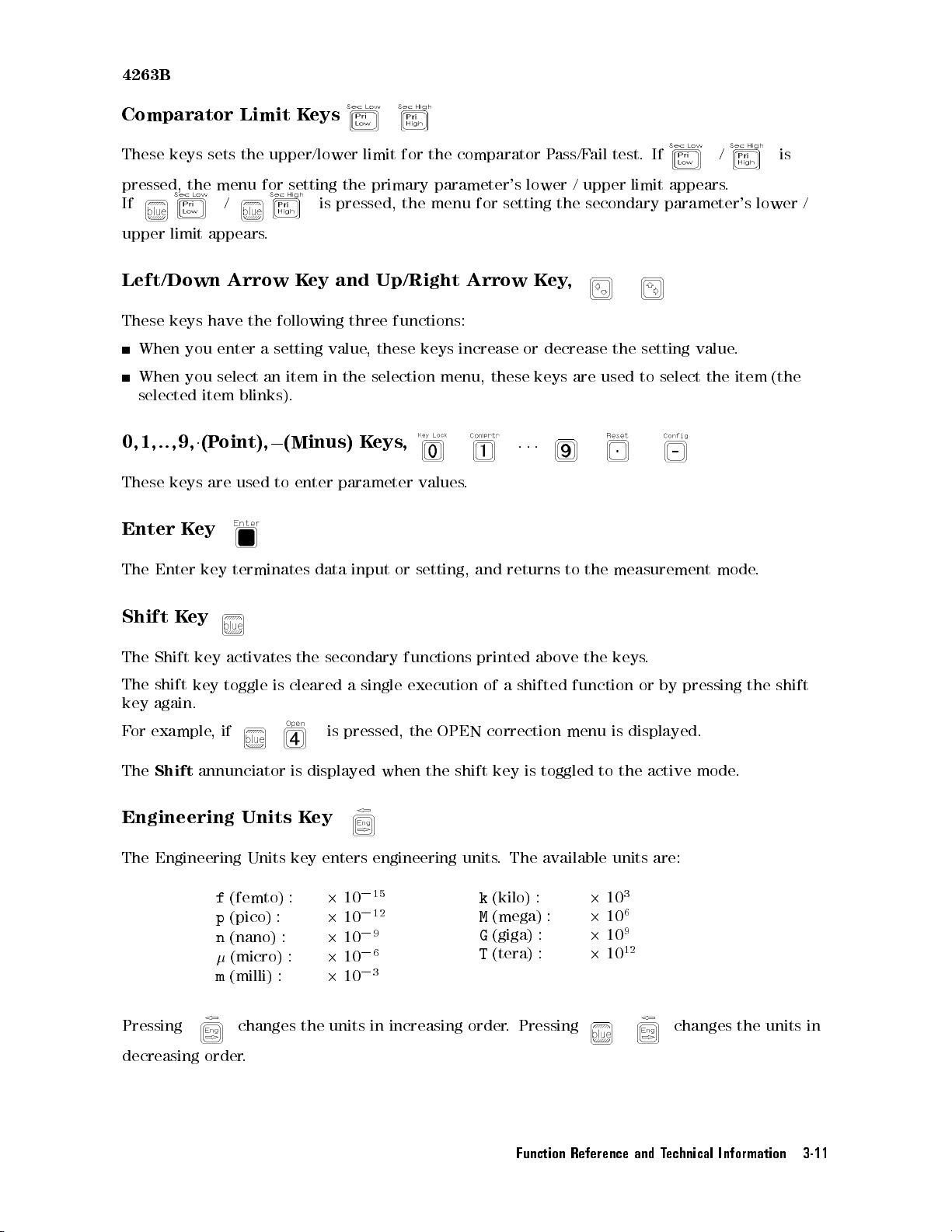
4263B
Comparator
These
pressed,
keys
the
sets
menu
If
upper
limit
appears
Left/Down
These
0,1,..,9,
These
Enter
keys
When
When
selected
keys
K
you
you
1
ey
have
enter
select
item
(P
oint),
are
Limit
the
K
eys
upper/lower
for
setting the
limit for
primary parameter's
/ is pressed,
.
Arrow
the
K
following
a
setting
an
item
ey
and
value
in
the
Up/Right
three
,
these
selection
blinks).
0
used
(Minus)
to
enter
K
eys
parameter
the comparator
the menu
functions:
keys
menu,
,
values
for setting
Arrow
increase
these
.
Pass/F
lower /
the secondary
K
ey
,
or
decrease
keys
.
.
.
ail test.
upper limit
the setting
are
used to
If
/ is
appears.
parameter's lower
value.
select the
item (the
/
The
Enter
Shift
The
Shift
The
shift
key
again.
F
or
example
The
Shift
Engineering
key
K
ey
key
activates
key
toggle
,
if
annunciator
terminates
is
cleared
is
Units K
data
input
the
secondary
a
single
is
pressed,
displayed when
ey
or
setting,
functions
execution
the
OPEN
the shift
The Engineering Units key enters engineering
0
f
(femto) :
p
(pico)
n
(nano) :
(micro) :
m
(milli) :
2
:
2
2
2
2
10
10
10
10
10
15
0
12
0
9
0
6
0
3
and
returns
printed
of
a
shifted
correction menu
key is
to
above
toggled
the
measurement
the
keys
function
is displayed.
to
the
.
or
by pressing
active
units. The available units are:
k
(kilo) :
M
(mega) :
G
(giga) :
T
(tera) :
3
2
10
6
2
10
9
2
10
12
2
10
mode
mode
.
the shift
.
Pressing
decreasing order.
changes the units in increasing order. Pressing changes the units in
Function Reference and Technical Information 3-11
Page 86
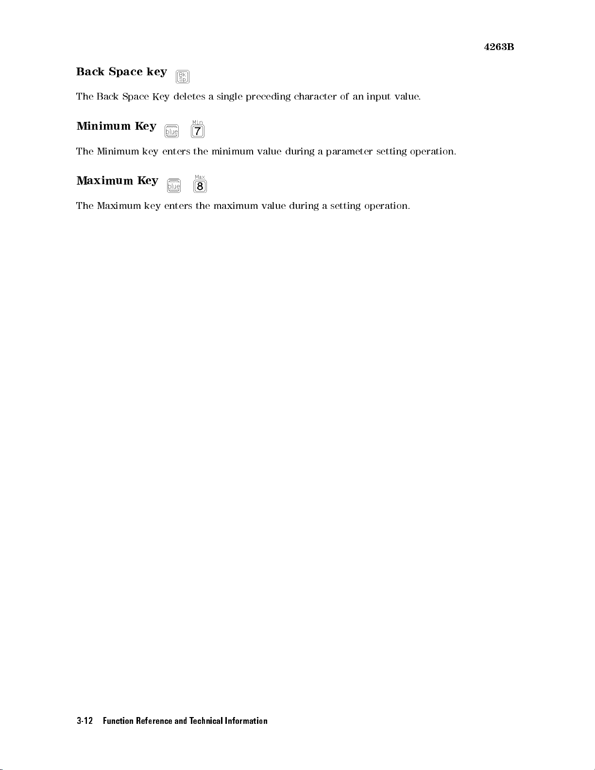
4263B
Back
The
Space
Back
Space
Minimum K
The
Minimum key
Maximum
The
Maximum
key
Key
ey
enters
K
ey
key enters
deletes
the
the maximum
a single
minimum
preceding character
value
during
value during
a
parameter
a setting
of an
input value
setting
operation.
.
operation.
3-12 Function Reference and Technical Information
Page 87
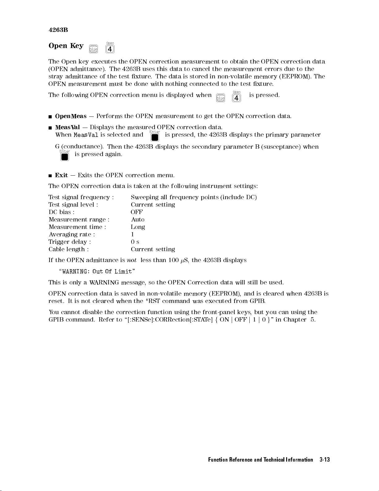
4263B
Open
The
(OPEN
stray
OPEN
The
K
ey
Open
key
admittance).
admittance
measurement
following
OpenMeas
MeasVal
When
G
(conductance).
Exit
The
OPEN
T
est
signal
T
est
signal
DC
bias
| Displays
MeasVal
is
pressed
|
Exits
correction
frequency
level
:
Measurement
Measurement
A
veraging
Trigger
Cable
rate
delay
length
executes
of
OPEN
|
Performs
is selected
the
:
range
time
:
:
:
the
The
4263B
the
test
must
be
correction
the OPEN
the measured
Then
the
again.
OPEN
correction
data
:
:
:
OPEN correction
uses
this data
xture.
done
The data
with nothing
menu
is displayed
measurement
OPEN
and
4263B
is pressed,
displays
menu.
is
taken
Sweeping
Current
at
the
all
setting
OFF
A
uto
Long
1
0
s
Current
setting
measurement to
to cancel
is stored
connected to
when
to
correction
the 4263B
the
secondary
following
frequency
obtain the
the measurement
in non-volatile
the test
get
the
OPEN
data.
displays the
parameter
instrument
points
(include
is
correction
settings:
DC)
OPEN correction
errors due
to the
memory (EEPROM).
xture.
pressed.
data.
primary
B
(susceptance)
parameter
when
data
The
If
the OPEN
\
WARNING: Out
This
is only
OPEN
reset.
Y
GPIB
correction data
It
ou
cannot
command.
admittance
aW
is
not
disable
Of Limit
ARNING
cleared
the
Refer
is
not
less
than
100
"
message
is saved
when
correction
to
\[:SENSe]:CORRection[:ST
,
so
the
in non-volatile
the
*RST
command
function
OPEN
using
S,
the
Correction
memory
was
the
4263B
displays
data
(EEPROM),
executed
front-panel
A
T
e]
f
ON
will
from
keys
j
OFF
still
and
GPIB
j
,
1
be
is
but
j
used.
cleared
.
you
0
g
"
in Chapter
can
when
using
4263B
the
5.
is
Function Reference and Technical Information 3-13
Page 88
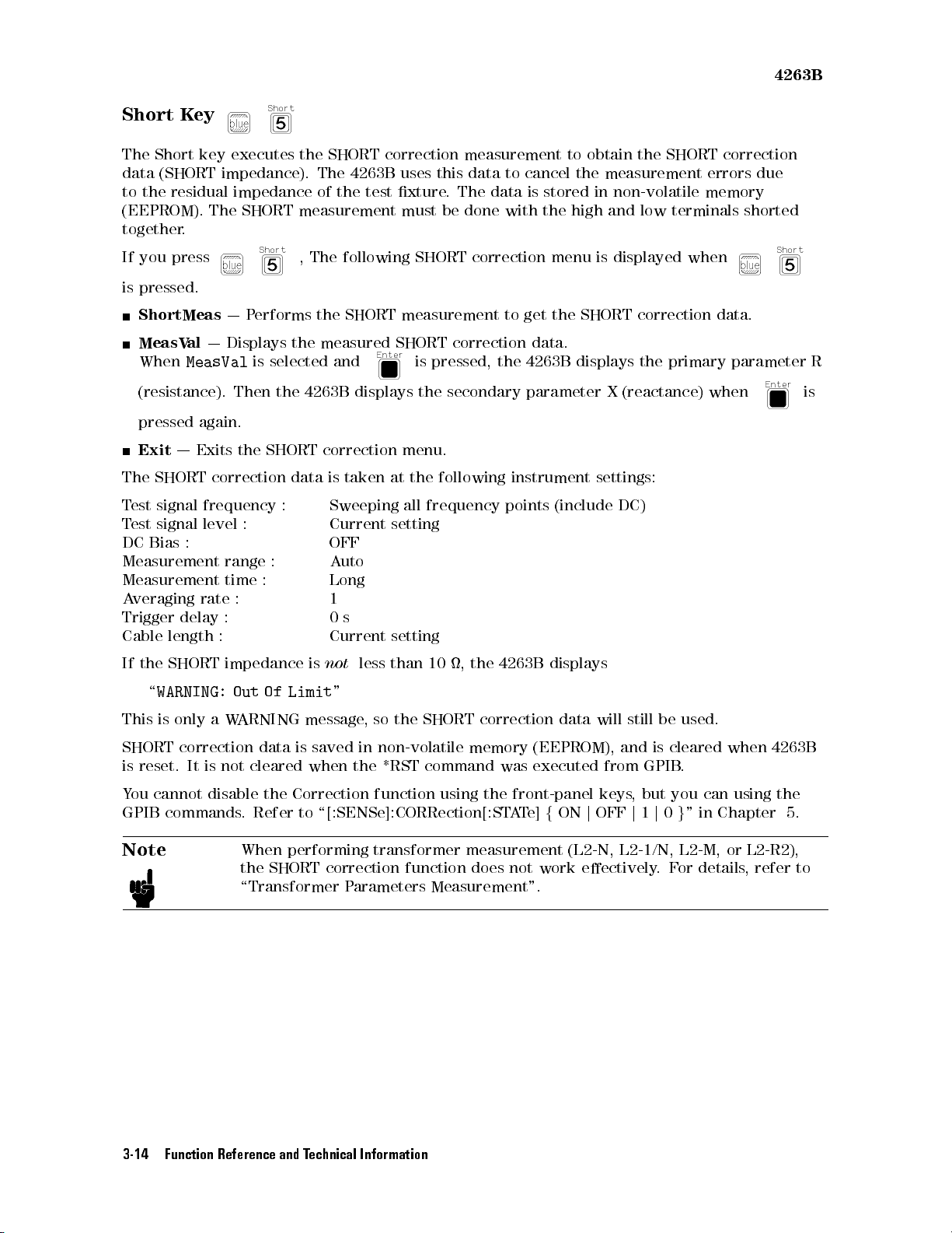
4263B
Short
The
data
to
Short
(SHORT
the
K
ey
key
residual
(EEPROM).
together
If
is
.
you
press
pressed.
ShortMeas
MeasV
When
al
| Displays
MeasVal
(resistance).
pressed again.
Exit
|
Exits
The
SHORT
T
est
signal frequency
T
est
signal
level
DC
Bias
:
Measurement
Measurement
A
veraging
Trigger
rate
delay
Cable length
executes
the
impedance).
impedance
The
SHORT
measurement
,
|
Performs
the measured
is selected
Then the
the
4263B
SHORT correction
correction data
: Sweeping
: Current
range
time
:
:
:
:
:
SHORT correction
The
of
the test
4263B
uses this
xture.
must
The
following
the SHORT
measurement to
SHORT correction
and
displays
menu.
is taken
at the
all frequency
setting
OFF
A
uto
Long
1
0
s
Current
setting
be done
SHORT
is
pressed,
the
secondary
following
measurement to
data to
The data
cancel the
is stored
with the
correction
get
menu is
the
data.
the 4263B
parameter
instrument
points (include
obtain the
SHORT correction
measurement errors
in non-volatile
high and
low terminals
displayed when
SHORT
displays the
correction
X
(reactance)
primary parameter
settings:
DC)
memory
shorted
data.
when
due
R
is
If
the
\
WARNING:
This
is
SHORT
is
reset.
Y
ou
cannot
GPIB
Note
SHORT
only
impedance
a
W
correction
It
is
not
disable
commands
is
not
less
than
10
,
the
Out
Of
ARNING
data
cleared
the
.
Refer
Limit
"
message
is
saved
when
Correction
to
,
so
the
SHORT
in
non-volatile
the
*RST
command was
function
\[:SENSe]:CORRection[:ST
using
4263B
correction
memory
the
displays
data
will
(EEPROM),
executed from
front-panel keys
A
Te]
f
ON
j
OFF
still
and
,but
j
be used.
is
cleared
GPIB.
you can
1
j
0
g
"
in
Chapter
when
4263B
using the
When performing transformer measurement (L2-N, L2-1/N, L2-M, or L2-R2),
the SHORT correction function does not work eectively
.F
or details
, refer to
\Transformer Parameters Measurement".
5.
3-14 Function Reference and Technical Information
Page 89
4263B
Load
The
a
LO
K
Load
AD
standard
correction
error
resulting
the
OPEN/SHORT
The
LO
AD
an
Agilent
The
following
On/O
If you
On
O
LoadMeas
Corval
If
you
PrmSlct
ey
Key
executes
in
addition
correction
test
LO
|
The
select
|
|
The menu
select
device
from
the
correction.
xture
AD
correction
menu
On/Off
Turns
Turns
Measures
CorVal
The
the
LOAD
which has
to
the
OPEN/SHORT correction,
complex
is
not necessary
to
the 4263B
to
toggle
,
the
following
ON
the
OFF
the LO
the
LO
for entering
,the
following menu
menu
for
correction. The
been previously
residual impedance
when performing
.
menu is
ON/OFF
LO
AD
displayed when
of
the
menu
appears
AD
correction.
AD
correction.
standard
the LO
AD standard's
to
appears
selecting the
parameter model
LOAD
measured. By
the 4263B
which cannot
LO
AD
correction
.
Load
Load
get
the
.
correction is
performing the
can remove
be completely
a measurement
is
On
annunciator
On
annunciator
LO
AD
correction
reference
of
value
the
performed by
measurement
by directly
pressed.
appears
.
disappears
data.
LO
AD
standard
connecting
LOAD
removed by
connecting
.
If
you
select
RefEnt
MeasV
al
Exit
Exit
| Exits the LO
PrmSlct
secondary
F
or
example
Cp is
secondary
The
If
you
primary
the
LO
Displays
If
you
measured
selected
menu
select
parameter
AD
the
select
parameter
,
when
here
parameter
for
entering
RefEnt
reference
measured
MeasVal
LO
AD
Exits this menu and return to the LO
AD correction main menu.
,
the
will
the
LO
for
the
.
the
,
the
and
the
value
LO
,
the
correction
menu
appear
AD
standard
primary
LO
AD
menu
for
secondary
here
.
AD
correction
primary
data
for
selecting
in
turn.
has
parameter
reference
entering
parameter
the
been
,
value
the
primary
assigned
and
D
reference
will
data.
and
will
secondary
be
displayed in
parameters of
AD correction main menu.
The LOAD standard measurement is executed with the following settings
Test Signal Frequency
Test Signal Level
DC Bias
Measurement Range
Current setting
Current setting
OFF
Auto
Measurement Time LONG
Averaging Rate 1
Trigger Delay Time 0s
Cable Length Current setting
is
selected
appear
turn.
.
parameter
a
value
here
value
of
in
turn.
the
of
Cp-D
the
and
for
Enter
the
,
the
Function Reference and Technical Information 3-15
Page 90
If
the dierence
20
%,
the
\
WARNING: Out
This
is only
The
LO
AD
4263B
is
reset.
between the
4263B
a
W
displays
ARNING
correction
It
4263B
LO
AD
measurement
Of
Limit
"
message
data
is
not
cleared
is
,
saved
when
so
the
in
non-volatile
the
LO
*RST
AD
value
correction
memory
command
and
reference
data
will still
(EEPROM),
was
executed
value
be used.
and
is
from
is
more
cleared
GPIB.
than
when the
Comparator K
The
Comparator key
whether
the
Comptr
LCD
The
HI
IN (in)
LO (low)
N.C.
In
the
measurement
Primary
display
and
On
annunciator
,
can
comparator
(high)
:
: Between
: Less
(no-contact)
addition,
these
Destination
Comparison
Handler
Beep
Note
Display
Interface
(F
AIL
mode)
(P
ASS
mode)
When
comparator
ey
toggles the
Secondary
will
be
output
will
yield
Greater
: Contact
results
are
:
:
:
:
the measurement
comparator
result
(displayed
Comparator
be
displayed.
to
the
handler
one
of
the
than
the upper
than lower
check failed
transmitted
HI,
IN,
LO
HI,
IN,
LO
HI,
LO
,
IN
function is
function
value)
Limit
keys
The
comparison
interface
following
upper
limit
limit
results:
and
limit
(at
contact
to
the
following
Condition
,
N.C.
,
N.C.
N.C.
parameter or
automatically turned
is
within
.
When
,
or
lower
ON
and
the
the
can
be
limit
check
destinations:
the
deviation
OFF
.
The
upper
comparator
results
can
revealed
ON
state)
mode
OFF
.
comparator
and
lower
function
be
displayed
by
the
beeper
is
changed,
determines
limits
set
is
ON,
on
.
the
by
the
the
3-16 Function Reference and Technical Information
Page 91
4263B
Contact
The
Contact
whether
When
N.C.
The
Check
Check
the
DUT
the
contact
(No-Contact)
measurement
Key
The /NO
the pin
CONTA
assignment
The measurement
interface and
To
detect
performed
and SHORT
The
a
properly
available
no-contact
corrections
K
key
is
properly
check
status
"
for
CT pin
is
the
handler
.
range of
ey
toggles
connected to
fails
,
will
be
displayed
of
the
the
GPIB
of
the
of
the
handler
still
performed,
interface
condition
Because the
as
reference
the contact
Measurement
Range
the contact
check function
the test
on the
LCD display
GPIB output
output
handler
data.
interface
interface
but
the
.
.
correctly
contact
values
,
the
check
.
OPEN
check function
Setup
0.1
1
10
100
1
10
k
k
5
50
500
900
9
100 k 90 k
1
M
900
electrodes.
.
data is
set to
is
asserted.
measurement
and
SHORT
function
uses
is restricted
Contact
A
vailable
m
m
m
5
k
k
<
<
<
<
j
<
j
Z
<
j
Z
j
j
Z
Check
j
<
j
Z
j
j
Z
j
<
Z
j
j
<
Z
j
j
Z
j
Range
<
j
<
<
<
ON and
OFF.
2 (No-Contact).
Refer
to
\Handler
result
is
output
corrections
the
values
as
follows:
0.11
1.1
<
11
2
k
20
k
200
k
2
M
20 M
This function
Refer
to
Interface
to
the
GPIB
must
be
taken
by
the
monitors
\A
ddress
"
for
OPEN
F
or
the
Note
DUT
s
which
The
parameters
001 only).
are
out
of
these
contact check
,
L2-N
ranges
function
,
L2-1/N
,
,
L2-M
the
is
contact
not
,
and
check
available
L2-R2
result
with
the
(parameters
will
always be
transformer
available
N.C.
measurement
with
Function Reference and Technical Information 3-17
.
Option
Page 92
4263B
Cable
The
P
arasitics
4263B
Cable
Cable
Length
0m
1
m
2
m
has
1
K
ey
key
and
four
4m Termination
1
Default
2
Option 002
only
Note
allows
phase
you
shift
reference
Reference
UNKNOWN T
T
ermination
T
ermination
In
the
2
frequency
exceeded,
which
T
\A
is
ouse
this function,
ccessories
length.
to accurately
due to
plane
the cable
as follows:
Plane
erminal
of
16089A/B/C/D
of
16048D
of
16048E
m
and
4
m
.
If
changing
the
4263B
within
the
A
vailable"
extend your
are automatically
100 Hz,
100
100
100 Hz,
settings
will
the
,the
cable
set
the
frequency
you must
in
Chapter
measurement or
A
vailable
120 Hz,
Hz,
120
Hz,
Hz,
120
Hz,
120
Hz,
4263B has
length causes
frequency
limits
for
the
use the
1
for
Agilent's
applicable
reference plane
removed with
Frequency
1kHz,
1
1
1
limits on
10
kHz, 10
kHz,
10
kHz
kHz
kHz, 20
kHz,
the
the frequency
to
the
maximum
selected
test
cable
leads
test
the Cable
Range
,
20
20
usable
limits
frequency
length.
.
Refer
leads
and
kHz
kHz
kHz
test
.
key.
2
2
2
signal
to
their
,100
,
100
to
be
The
kHz
kHz
K
ey
The
lock
Note
Lock
Key
lock
condition,
K
key
ey
press
The
the
the
locks out
Key
lock
Key
lock
,
will
handler
all
be
.
front
state
state
locked.
panel
again.
can
is
set
The
also
by
In
keys
be
the
this
input
key
lock
controlled
handler
case
,the
except
state is
from
,
all
Key lock
for
indicated
the
front
this
key
by
handler
panel
keys
state can
.
T
o
the
interface
,
only
cancel
the
annunciator
.
including
be
released
key
.
When
by
3-18 Function Reference and Technical Information
Page 93
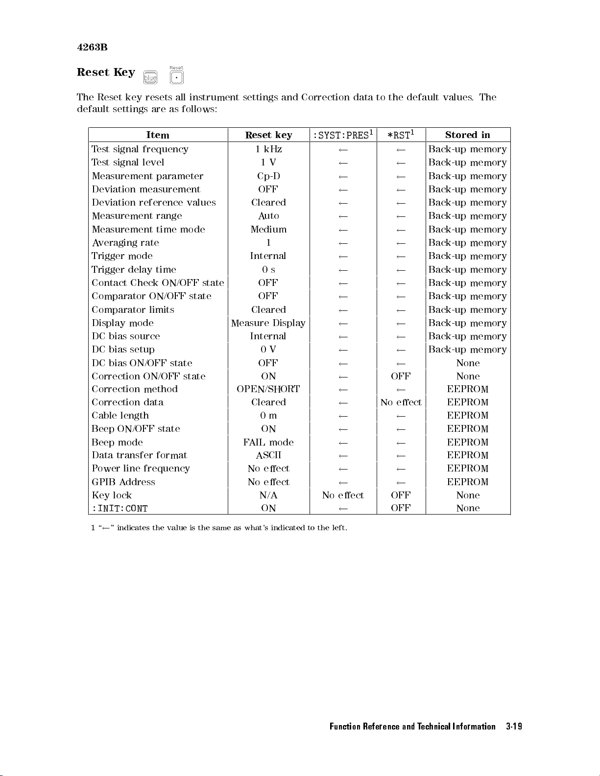
4263B
Reset
The
default
K
Reset
settings
ey
key
resets
are
all
instrument settings
as
follows:
Item Reset
T
est
signal
frequency
T
est
signal
level
Measurement
parameter
Deviation measurement OFF
Deviation
Measurement
Measurement
A
veraging
Trigger
Trigger
Contact Check
Comparator
Comparator
Display
DC
bias
DC
bias setup
DC
bias
Correction
Correction
Correction
Cable
Beep
Beep
Data
P
ower
GPIB
Key
reference values
range
time
rate
mode
delay
time
ON/OFF
ON/OFF
limits
mode
source
ON/OFF
ON/OFF
method
data
length
ON/OFF state
mode
transfer
line
A
ddress
format
frequency
lock
mode
state
state
Measure
state
state
OPEN/SHORT
:INIT:CONT
and Correction
key
1
kHz
1
V
Cp-D
Cleared
A
uto
Medium
1
Internal
0
s
OFF
OFF
Cleared
Display
Internal
0
V
OFF
ON
Cleared
0
m
ON
F
AIL
mode
ASCII
No
eect
No
eect
N/A No
ON
data to
the default
:SYST:PRES1*RST
OFF None
No
eect
eect
OFF None
OFF None
values.
1
Stored
Back-up
Back-up
Back-up
Back-up memory
Back-up
Back-up
Back-up
Back-up
Back-up
Back-up
Back-up memory
Back-up
Back-up
Back-up
Back-up
Back-up
None
EEPROM
EEPROM
EEPROM
EEPROM
EEPROM
EEPROM
EEPROM
EEPROM
The
in
memory
memory
memory
memory
memory
memory
memory
memory
memory
memory
memory
memory
memory
memory
1
\
"
indicates
the value
is
the
same
as
what's
indicated
to
the
left.
Function Reference and Technical Information 3-19
Page 94
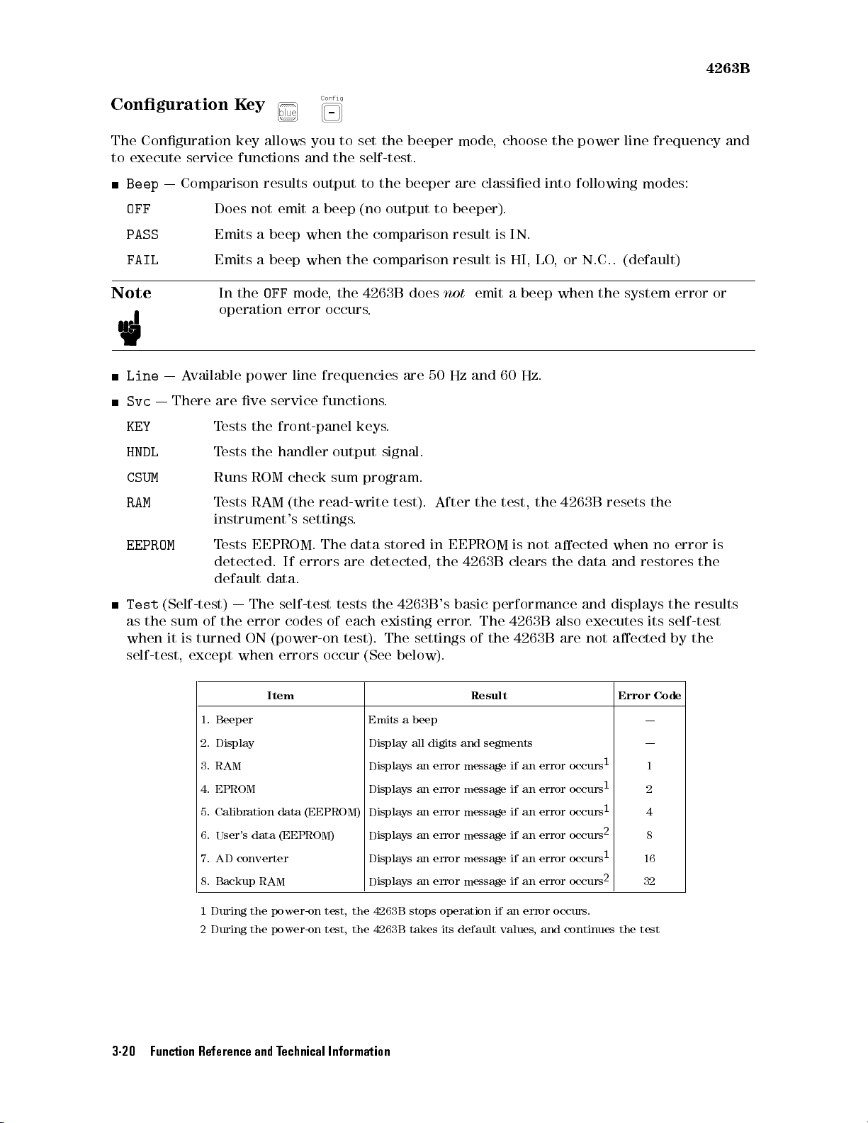
4263B
Conguration
The
Conguration
to
execute
Beep
OFF
PASS
FAIL
service
|
Comparison
Does
Emits
Emits
Note
Line
|
A
vailable
Svc
|
There
KEY
HNDL
CSUM
RAM
are
T
T
Runs
T
instrument's
K
ey
key
allows
functions
results
not
a
beep
a
beep
In
the
OFF
operation
power
ve
service
ests
the
ests
the
ROM
ests
RAM
you
to set
and
the self-test.
output
emit
a
beep (no
when
when
mode,
error
line
the
occurs
frequencies
functions
front-panel
handler
check
(the
output
sum
read-write
settings
the beeper
to the
beeper are
output to
the comparison
the comparison
4263B
does
.
are
50
.
keys
.
signal.
program.
test).
After
.
mode,
classied into
beeper).
result is
result is
not
emit
Hz
and
the
choose the
IN.
HI, LO
a
60
test,
,or
beep
Hz.
the
power line
following modes:
N.C..
(default)
when
the
system
4263B
resets
frequency and
error
or
the
EEPROM
Test
(Self-test)
as
the
sum
when
it
self-test,
T
ests
of
is
turned
except
EEPROM.
detected.
default
|
The
the
error
ON
when
data.
(power-on
errors
If
errors
self-test
codes
The
are
tests
of
test).
occur
data
stored
detected,
the
each
existing error
The
(See
in
4263B
settings
below).
EEPROM
the
4263B
's
basic performance
.The
of the
is
not
clears
4263B
4263B are
aected
the
data
and displays
also
executes
not
Item Result Error
1.
2.
3.
Beeper
Display
RAM
Emits
Display
Displays
a
beep
all
an
digits
error
and
segments
message
if
an
error
occurs
4. EPROM Displays an error message if an error occurs
5. Calibration data (EEPROM) Displays an error message if an error occurs
6. User's data (EEPROM) Displays an error message if an error occurs
7. AD
converter
Displays an
error message if an error occurs
8. Backup RAM Displays an error message if an error occurs
1
During the power-on test, the 4263B stops operation if an error occurs.
2
During the power-on test, the 4263B takes its default values, and continues the test
when
and
aected
1
1
1
2
1
2
no
error
restores
the
its
self-test
by
Code
|
|
1
2
4
8
16
32
is
the
results
the
3-20 Function Reference and Technical Information
Page 95
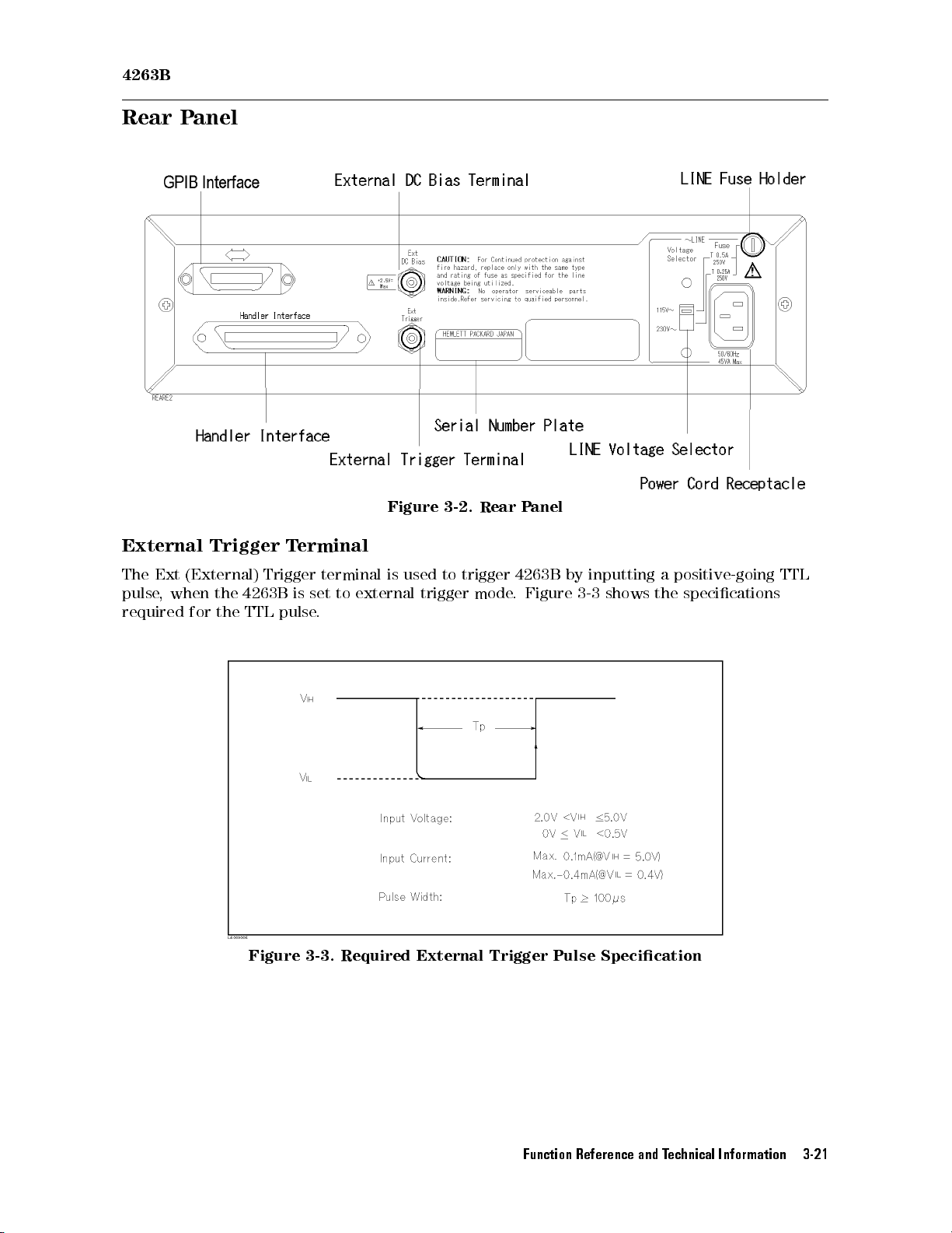
4263B
Rear P
External
anel
Trigger
T
erminal
Figure
3-2.
Rear
P
anel
The
Ext
pulse
,
when
required
(External)
the
4263B
for
the
TTL
Trigger
is
pulse
terminal
set
to
.
is
external
used
trigger
to
trigger
mode
4263B
.
Figure
by
inputting
3-3
shows
a
positive-going
the
specications
Figure 3-3. Required External Trigger Pulse Specication
TTL
Function Reference and Technical Information 3-21
Page 96
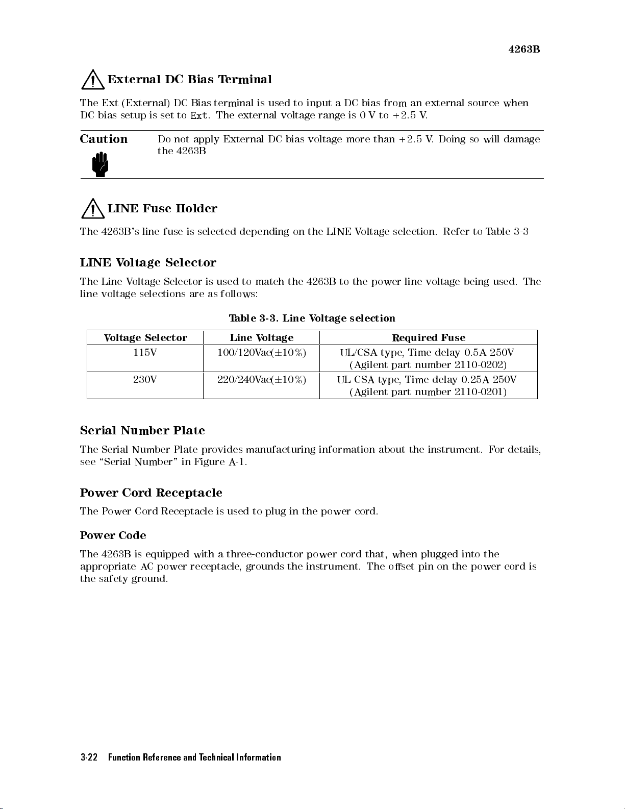
4263B
External
The
Ext
DC
bias
Caution
LINE
The
4263B
LINE
The
line
Voltage
Line V
voltage
V
oltage
DC
(External)
setup
is
Do not
the
Fuse
's
line
DC
set to
4263B
Holder
fuse
Bias
is
Terminal
Bias terminal
Ext
.
The external
apply External
selected
Selector
oltage
Selector
selections
is
are
as follows:
used
Selector
115V 100/120V
230V 220/240V
is used
depending
to
match
T
able
3-3.
Line
V
to input
voltage range
DC bias
on
the
Line
oltage
ac(
6
10%)
ac(
6
10%)
voltage
the
LINE V
4263B
V
oltage
aDC
bias from
is 0
Vto
more
than
oltage selection.
to
the
power
selection
UL/CSA
(Agilent
UL
CSA
(Agilent
+2.5 V
+2.5
Required
type
,
part
type
,
part
an external
.
V
.
Doing
Refer to
line
voltage
Fuse
Time
delay
number
Time
delay
number
source when
so
will
T
able
being
used.
0.5A
250V
2110-0202)
0.25A
250V
2110-0201)
damage
3-3
The
Serial
The
see
P
ower
The
P
ower
Number
Serial
\Serial
Cord
P
ower
Code
Number
Number"
Receptacle
Cord
Receptacle
Plate
Plate
The 4263B is equipped
appropriate A
C power receptacle
the safety ground.
in
Figure
provides
manufacturing
A
-1.
is used
to plug
in the
information
power cord.
about
the
instrument.
with a three-conductor power cord that, when plugged into the
, grounds the instrument. The oset pin on the power cord is
F
or
details
,
3-22 Function Reference and Technical Information
Page 97
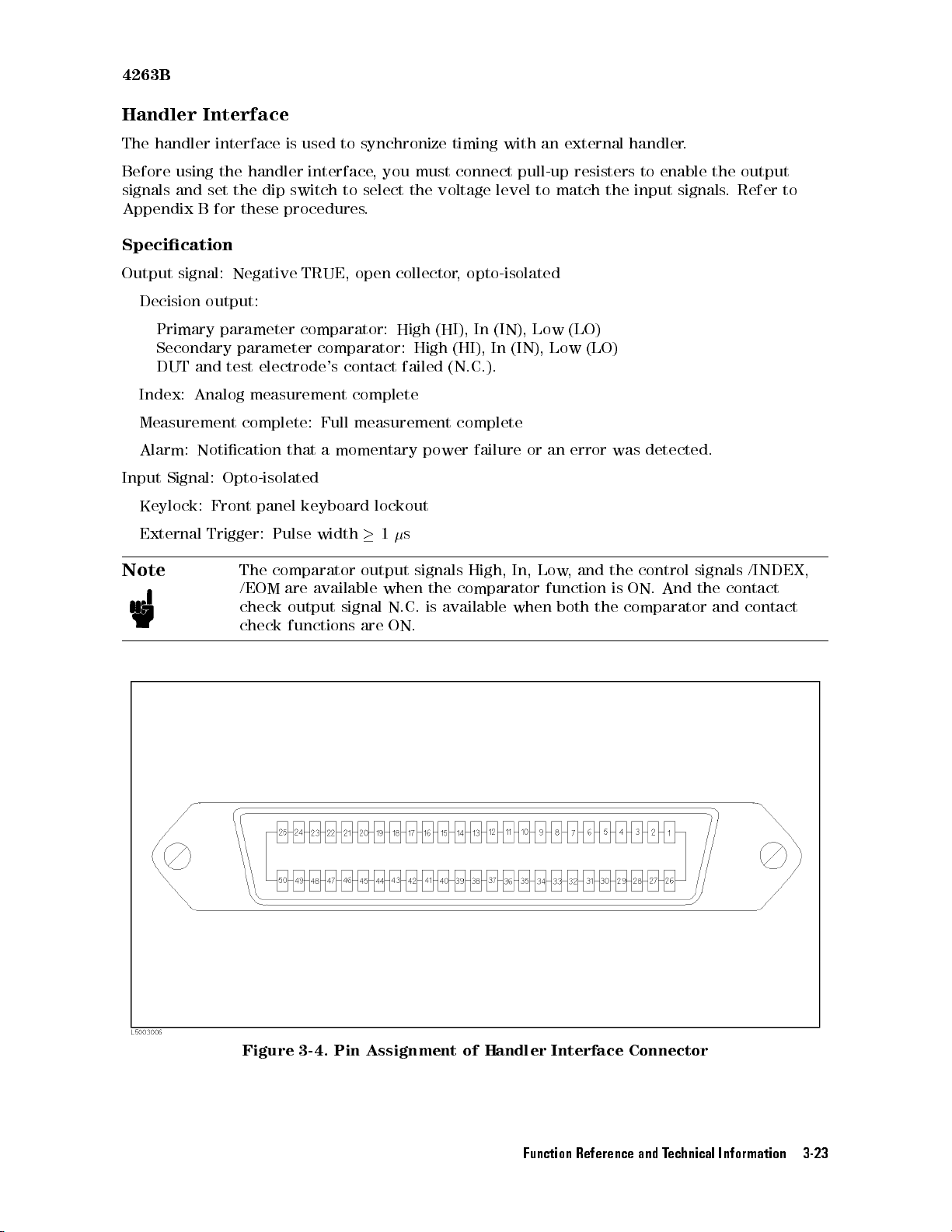
4263B
Handler
The
handler
Before
signals
Appendix
Interface
interface
using
the
and
set
B
for
Specication
Output
signal:
Decision
Primary
output:
parameter
Secondary
DUT
and
Index:
Analog
Measurement
Alarm:
Input
Keylock:
External
Notication
Signal:
Front
Trigger:
is
used
handler
the
dip
switch
these
procedures
Negative
TRUE,
comparator:
parameter
test
electrode's
measurement
complete:
that
Opto-isolated
panel
keyboard
Pulse
to
synchronize
interface
,
to select
.
open
comparator:
contact failed
complete
Full
measurement
a
momentary
lockout
width
you must
the voltage
collector
High
High
power
1
s
timing
with
connect pull-up
level to
, opto-isolated
(HI),
In
(IN), Low
(HI), In
(IN), Low
(N.C.).
complete
failure
an
external handler
resisters to
match the
(LO)
(LO)
or
an error
enable the
input signals
was
detected.
.
output
.Refer
to
Note
The
comparator
/EOM
check
check
are
available
output
functions
output
signal
are
when
N.C.
ON.
signals
the
is
available
High,
In,
comparator
when
Low
,
and
function
both
the
is
ON.
the
comparator
control
And
signals
the
contact
and
/INDEX,
contact
Figure 3-4. Pin Assignment of Handler Interface Connector
Function Reference and Technical Information 3-23
Page 98
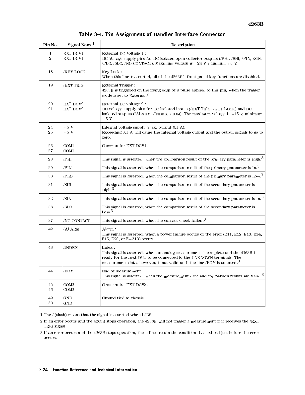
T
able 3-4.
Pin Assignment
of
Handler
Interface
4263B
Connector
Pin
No
.
1
2
18 /KEY
19 /EXT
20
21
24
25
26
27
Signal
EXT DCV1
EXT
DCV1
LOCK
TRIG
EXT
DCV2
EXT
DCV2
+5
V
+5
V
COM1
COM1
Name
1
28 /PHI This
29 /PIN This
30 /PLO This
31 /SHI This
32 /SIN This
External DC
DC
Voltage
/PLO
,
/SLO
Key
Lock
When
this
External
4263B
mode
External
DC
Isolated
+5
Internal
Trigger
is
triggered
is
set
DC
voltage
outputs (/ALARM,
V
.
voltage supply
Exceeding
zero
.
Common
for
signal
signal
signal
signal
3
High.
signal
Voltage
supply
,/NO
CONTA
:
line
is
asserted,
:
to
External.
voltage
supply
0.1
A
will
EXT
DCV1.
is asserted,
is
asserted,
is
asserted,
is
asserted,
is
asserted,
1:
pins
for
CT). Maximum
on
the
rising
2
2
:
pins
for
(max. output
cause
when the
when
when
when
when
Description
DC
isolated
open
voltage is
all
of
the
4263B
edge
of a
DC
Isolated
inputs
/INDEX, /EOM).
0.1
the
internal
voltage
comparison result
the
comparison
the
comparison
the
comparison
the
comparison result
collector
+24 V
's front
panel key
pulse applied
(/EXT TRIG,
The maximum
A):
output
of the
result
of
result
of
result
of
of
outputs
(/PHI,
, minimum
/SHI,
+5 V
functions are
to this
pin, when
/KEY LOCK)
voltage
and
primary
the
primary
the
primary
the
secondary parameter
the
secondary
the
is
+15
output
parameter
parameter
parameter
parameter
/PIN,
.
disabled.
the
and DC
V
,
signals
/SIN,
trigger
minimum
to
go
is
High.
3
is
In.
is
Low
is
is
In.
to
3
3
.
3
33 /SLO This signal
Low
37 /NO
CONT
A
CT
This
42 /ALARM Alarm
This
E15
43 /INDEX Index
This signal
ready
measurement
3
.
signal
signal
,
E20
:
,
or
:
for the
is
asserted,
is
asserted,
is
asserted,
E
0
313
)
is asserted,
next DUT
data, however
when
when
when
occurs
when an
to be
the
comparison
the
contact
a
power
.
analog
connected to
,is
not valid
result
check
failure
occurs
measurement
the
until
the
of
the
3
failed.
or
the
is
complete
UNKNOWN
line
/EOM
secondary
error
(
E11
and
terminals
is
asserted.
parameter
,
E12
,
E13
the
4263B
.
The
3
44 /EOM End of Measurement :
This signal is asserted, when the measurement data and comparison results are valid.
45
COM2
46
COM2
49
GND
50
GND
1
The / (slash) means that the signal is asserted when LOW
2
If an error occurs and the 4263B stops operation, the 4263B will not trigger a measurement if it receives the /EXT
Common for EXT DCV2.
Ground tied to chassis
.
.
TRIG signal.
3
If an error occurs and the 4263B stops operation, these lines retain the condition that existed just before the error
occurs.
is
,
E14
is
,
3
3-24 Function Reference and Technical Information
Page 99
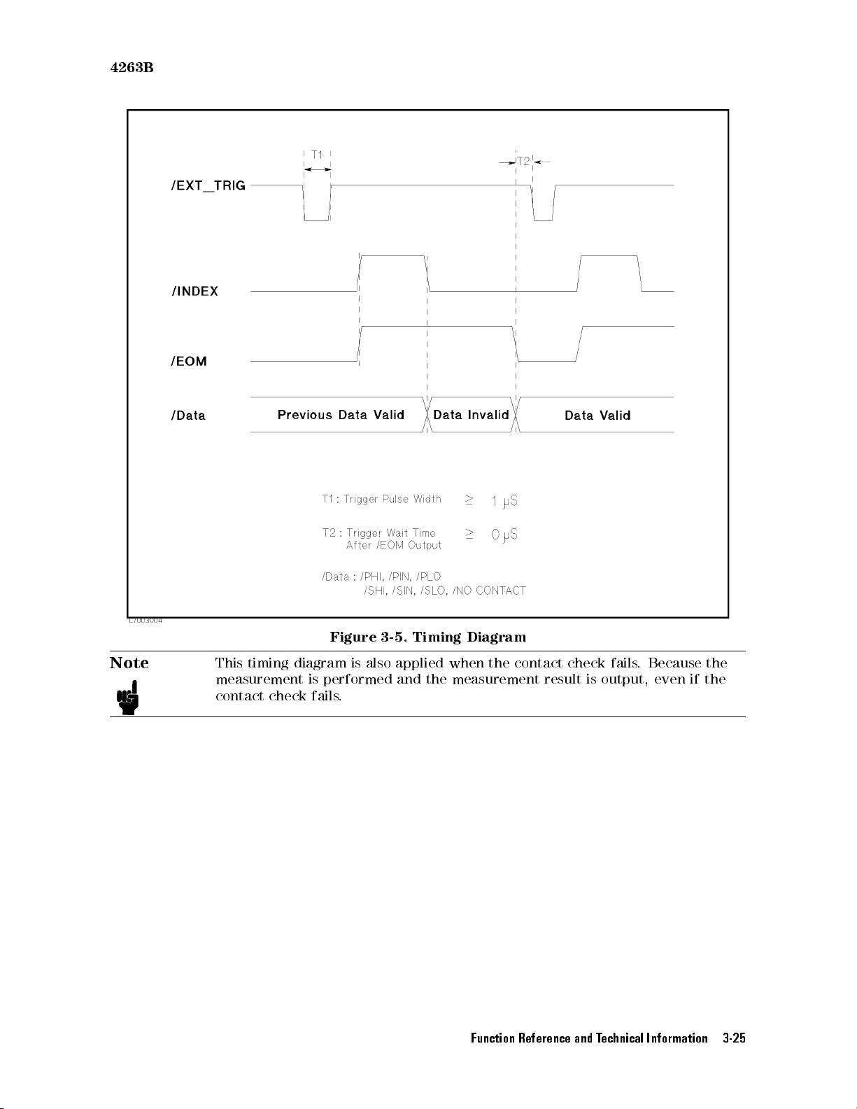
4263B
Note
This
timing
measurement
contact
check
Figure
diagram
is
performed
fails
3-5.
Timing Diagram
is
also
applied
and
when
the
measurement
the
contact
result
check
is
fails
.
output,
Because
even
the
if the
.
Function Reference and Technical Information 3-25
Page 100
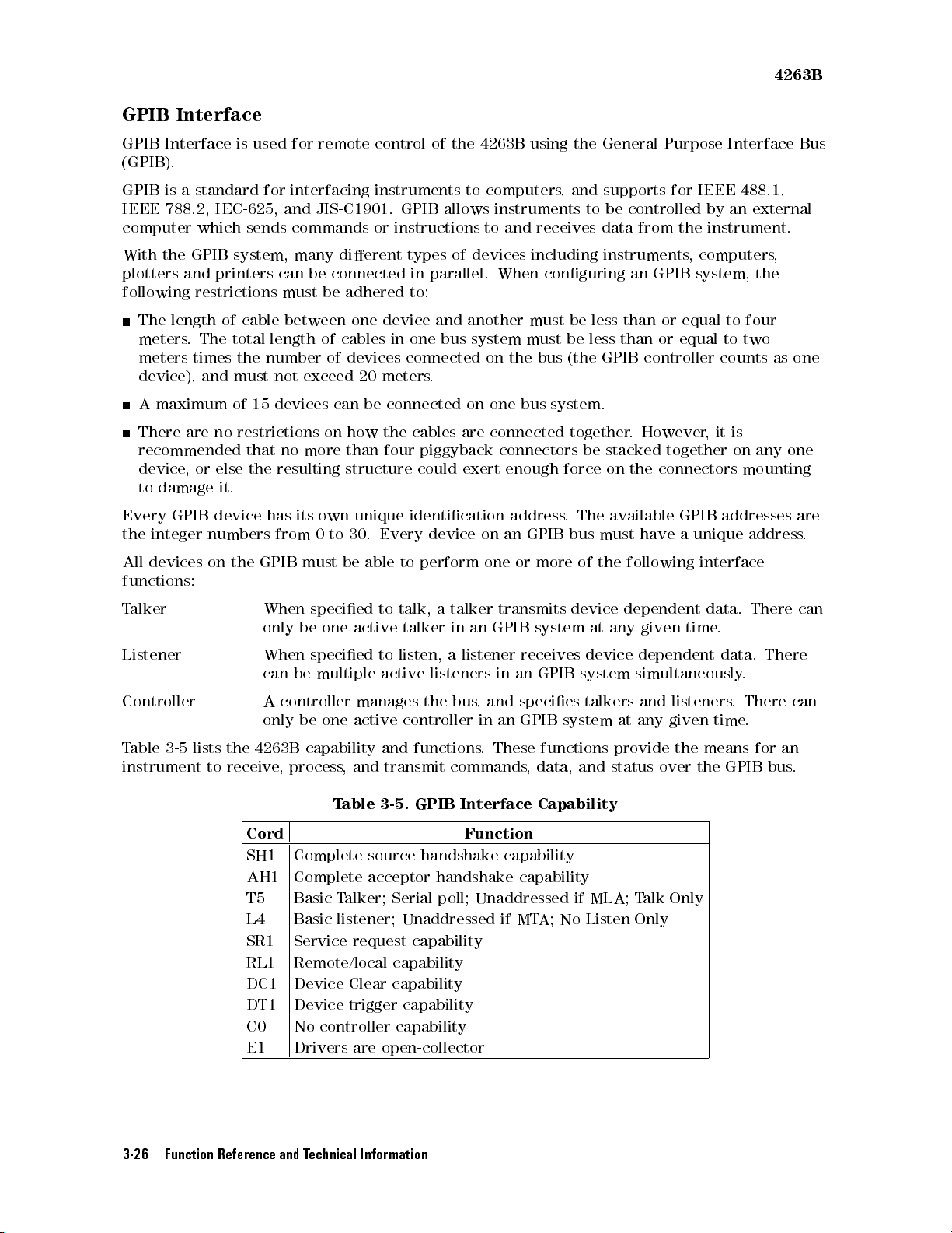
4263B
GPIB
GPIB
Interface
Interface
(GPIB).
GPIB
is
a
standard
IEEE
788.2,
computer
With
plotters
following
The
meters
meters
which
the
GPIB
and
restrictions
length
.
times
device),
A
maximum
There
are
recommended
device
,
or
to
damage
Every
the
All
GPIB
integer
devices
functions:
is
IEC-625,
system,
printers
of
The
total
the
and
must
of
no
restrictions
else
it.
device
numbers
on
the
used
for
sends
can
must
cable
length
number
not
15
devices can
that
no
the
resulting
has
from
GPIB
for
remote
interfacing
and
JIS-C1901.
commands
many
dierent
be
connected
be
between
of
cables
of devices
exceed 20
on
more
its
own
0
to
must
be
control
instruments to
GPIB
or
instructions
types of
in parallel.
adhered
one
to:
device and
in
one bus
connected on
meters.
be connected
how
the
than
four
structure
unique
30.
Every
able
to
identication
of
the
4263B
computers,
allows instruments
to
and
devices including
When conguring
another must
system must
on one
cables
are
piggyback
could
exert
device
perform
connected
connectors
enough
on
an
one
using the
receives
the bus
bus
system.
address
GPIB
or
more
General Purpose
and supports
to be
controlled by
data
from the
instruments,
an GPIB
be less
be less
(the
together
than or
than
GPIB
. However
be stacked
force
on
the
.
The
available
bus
must
have
of
the following
for IEEE
computers,
system, the
equal
or
equal
controller
together
connectors
GPIB
a
unique
interface
Interface Bus
488.1,
an external
instrument.
to
four
to
two
counts
,
it
is
on
as
any
mounting
addresses
address
one
one
are
.
T
alker
Listener
Controller
Table
3-5 lists
instrument to
When
only
When
can
A
only
the 4263B
receive,
specied
be
one
specied
be
multiple
controller
be
one
capability
process,
Table
to
active
to
active
manages
active
and
and
transmit
3-5. GPIB
talk,
a
talker
talker
listen,
in
a
listeners
the
bus
controller
functions
commands
transmits
an
GPIB
system
listener
receives
in
an
,
and
species talkers
in
an GPIB
.
These
,
Interface Capability
Cord Function
SH1 Complete source handshake capability
AH1 Complete acceptor handshake capability
T5 Basic T
alker; Serial poll; Unaddressed if MLA; T
L4 Basic listener; Unaddressed if MT
SR1 Service request capability
RL1 Remote/local capability
DC1 Device Clear capability
DT1 Device trigger capability
C0 No controller capability
E1 Drivers are open-collector
device
at
any
dependent
given
device dependent
GPIB
system simultaneously
and listeners
system at
functions
data,
and
any given
provide
status
alk Only
A; No
Listen Only
the
over
time
means
the
data.
.
data.
time.
GPIB
.
.
There
There
There
for
bus
can
can
an
.
3-26 Function Reference and Technical Information
 Loading...