

Page 1
Agilent
4286A RF
User's Guide
LCR
meter
This
above
manual
about
,
or
serial
applies
whose
numbers
directly
rmware
,
read
SERIAL
to
instruments
is
version
\Serial
NUMBERS
with
2.0. F
or additional
Number"
serial number
important information
in Appendix
prex JP3KC
Aof
this manual.
and
Agilent Part No. 04286-90031
Printed in JAPAN December 1999
Fifth Edition
Page 2
Notice
The
information
This
document
reserved.
language
contains
No
part
without
contained
proprietary
of
this
the
prior
in
this
document
written
document
information
may
be
consent
is
subject
that
is
photocopied,
of
the
Agilent T
to
change
protected
reproduced,
echnologies.
without
by
copyright.
or
notice
.
All
translated
rights
are
to another
Agilent
Component
1-3-2,
Hyogo
MS-DOS
APC-7
R
T
echnologies
T
Murotani,
,
651-2241
R
is
a
U
is
a
U
.S.
est
PGU-Kobe
Nishi-ku,
Japan
.S.
registered
registered
Japan,
Kobe-shi,
trademark of
Ltd.
trademark
of
Microsoft
Bunker
Corporation.
Ramo
Corporation.
c
Copyright 1995, 1998, 1999 Agilent Technologies Japan, Ltd.
Page 3
Manual Printing
The
manual
changes
at
reprint
technical
June
July
when
do
changes
1995
1995
printing
a
new
not
cause the
are
:
:
::
::
:
:
::
::
date
edition is
incorporated.
::
::
::
::
:
History
and part
date to
:
:
:
:
:
:
:
:
:
:
:
:
:
:
:
:
number indicate
printed. (Minor
change.)
:
:
:
:
:
:
:
:
:
::
::
::
:
:
:
:
:
:
:
:
::
::
::
its current
corrections and
The manual
::
:
:
:
:
:
:
:
:
:
::
:
:
:
:
:
:
:
Second
edition. The
updates that
part number
First
Edition
Edition
printing date
are incorporated
changes when
(part
number:
(part
number:
extensive
04286-90001)
04286-90011)
September
April
1999
December
1998
:
:
::
1999
::
::
:
::
:
::
::
::
::
:
:
:
:
:
:
:
:
:
:
:
:
:
:
:
:
:
::
::
::
::
:
:
Third
::
::
::
Edition
:
:
:
:
:
:
:
:
:
:
:
:
:
:
:
:
:
::
::
::
::
:
:
:
:
:
:
:
F
ourth
Edition
:
:
:
:
:
:
:
:
:
:
:
:
:
:
:
:
:
:
:
::
::
::
:
:
:
:
:
:
:
Fifth
Edition
(part
(part
(part
number:
number:
number:
04286-90021)
04286-90031)
04286-90031)
iii
Page 4
Safety Summary
The
following
service
W
ARNINGS
In
addition
,
and
elsewhere
it
general
repair
violates
safety
of this
in
safety standards
instrument.
The
A
gilent
requirements
T
echnologies assumes
.
precautions must
instrument. F
this manual
no liability
be observed
ailure to
may impair
of design,
for the
during all
comply with
the protection
manufacture,
customer's failure
phases of
these precautions
provided by
and intended
the equipment.
use of
to
comply
operation,
or with
the
with
specic
these
Note
4286A
61010-1
4286A
Note
LEDs
CLASS
Ground
T
o
avoid
safety
DO
Do
not
electrical
Keep
earth
NOT
operate
A
way
The
Instrument
electric
shock
ground
Operate
the
instrument
From
Operating personnel
adjustments
with
the
with
the
circuits
power
power
before
must
cable
cable
touching
be
is
designed
and
is
an
INDOOR
in
4286A
1
LED
hazard,
by
the
supplied
In
An
instrument
in
such
Live
must
not
made
by
connected.
removed.
them.
for
use
POLLUTION
USE
are
Class
PRODUCT
the
instrument
power
Explosive
in
the
presence
an
environment
Circuits
remove
instrument
qualied
Under
T
o
avoid
in
INST
ALLA
DEGREE
product.
1
in
accordance
chassis
cable
with
Atmosphere
of
ammable
constitutes
covers
maintenance
certain
injuries
conditions
,
always
TION
1
according
with
and
cabinet
earth
a
denite
.
Component
personnel.
,
disconnect
CA
TEGORY
to
IEC
IEC60825-1.
must
blade
.
gasses
or
safety
Do
not
dangerous
II
according
61010-1
be
connected
fumes
.
Operation
hazard.
replacement
replace
voltages
power
and
to
IEC
and
IEC
60664-1.
to
a
of
and
internal
components
may
exist
discharge
any
even
DO
NOT
Service
Or
A
djust
Alone
Do not attempt internal service or adjustment unless another person, capable of rendering rst
aid and resuscitation, is present.
DO NOT Substitute P
Because of the danger of introducing additional hazards
arts Or Modify Instrument
, do not install substitute parts or
perform unauthorized modications to the instrument. Return the instrument to a Agilent
T
echnologies Sales and Service Oce for service and repair to ensure that safety features are
maintained.
iv
Page 5
Dangerous
W
arnings
this
,
manual.
Procedure
such
as
the
Instructions
W
arnings
example
contained
below
in
,
precede
the
warnings must
potentially dangerous
be followed.
procedures throughout
W
arning
Dangerous voltages
instrument. Use
extreme caution
this instrument.
, capable
of
causing
when handling,
death,
are
present
testing,
in
and
this
adjusting
v
Page 6

Typeface Conventions
Bold
Italics
Computer
4
HARDKEYS
N
NN
NN
NN
N
N
5
N
N
N
N
N
N
N
N
N
N
N
N
N
N
N
N
N
SOFTKEYS
Assistance
Product
Agilent
F
or
A
ddresses
maintenance
T
echnologies
any
assistance
are provided
Boldface
symbols
Italic
publications
Italic
must
lename
type
Computer
Labeled
Softkeys located
agreements
products
,
contact
at
your
the
type
type
be
the
.
back
type
.
is
.
is
typed
means
name
font
keys
and
nearest
of
is
used
used
also
in
to
of
is
on
the
other
Agilent T
this
when
for
emphasis
used
place
type
a
le
used
instrument
to the
customer
manual.
a
term
is
and for
for
keyboard
of
the
words
the
word
copy
such
as
file1
for
on-screen
front
right
of
the
assistance agreements
echnologies Sales
dened.
titles of
entries
in
italics
,to
when
.
type a
.
prompts and
panel
are
CRT
are
enclosed
and
F
or example:
manuals and
a
name
For
example:
space,
messages.
enclosed in
in
are available
Service
Oce
icons
other
or a
variable
copy
and then
5
.
4
N
NN
NN
.
.
are
to
for
Safety
General
Symbols
denitions
Instruction manual
necessary for
Alternating current.
Direct
On
O (Supply).
This
condition or
result in
This
condition or the like
result in damage to or
Note
practice, condition or the like, which is essential to highlight.
Axed to product containing static sensitive devices use anti-static handling
procedures to prevent electrostatic discharge damage to component.
of
safety
symbols
the user
used
on equipment
symbol: the
to
refer
product
to
the
or in
manuals
is
marked
instruction
are
with
manual.
this
listed
symbol
current.
(Supply).
Warning
sign denotes a hazard. It calls attention to a procedure
the like
, which, if not correctly performed or adhered to
injury or death to personnel.
Caution
sign denotes
a hazard. It calls attention to a procedure
, which, if not correctly performed or adhered to
destruction of part or all of the product.
denotes important information. It calls attention to a procedure,
below
when
.
it
is
, practice
, could
, practice
, could
,
,
vi
Page 7
Contents
1.
Brief
Description
Front
and
2.
Installation
Incoming
Rack
Mounting
P
ower
Cable
P
ower
Requirements
V
entilation
Instruction
Connecting the
of
Rear
P
anels
and
Set
Inspection
.
.
.
.
.
Requirements
for
Cleaning
Connector Box
the
Up
.
.
.
.
4286A
.
.
Guide
.
.
.
.
.
.
.
.
.
.
.
.
.
.
.
.
.
.
.
.
..
..
..
..
.
.
.
.
.
.
.
.
1-2
.
.
.
.
.
.
.
.
.
.
.
.
.
.
..
..
..
.
.
.
.
.
.
2-1
.
.
.
.
.
.
.
.
.
..
..
..
.
.
.
.
.
.
.
.
.
.
.
2-3
.
.
.
.
.
..
..
..
.
.
.
.
.
.
.
.
.
.
.
.
.
.
.
2-5
.
.
.
.
.
.
.
.
.
..
..
..
.
.
.
.
.
.
.
.
.
.
.
2-7
.
.
.
.
.
.
.
.
.
.
.
.
.
..
..
.
.
.
.
.
.
.
.
.
2-7
.
.
.
.
.
.
.
.
.
.
.
.
.
.
.
.
.
.
..
.
.
.
.
.
.
2-7
.
.
.
.
.
.
.
.
.
.
.
.
.
.
.
.
.
.
.
..
..
. 2-7
Connecting
Connecting
Connecting
Connecting
3.
Basic
Measurement
1.
2.
3. Calibration . . . . . . . . . . .
4. Connecting the T
5. Setting the Electrical Length of the T
6.
7. Connecting the DUT to the Test Fixture ........ ...... .... 3-19
8. Measuring the DUT ............................ 3-20
Measurement
Basic
Measurement
Required
P
ower
ON
Line
Input
Fuse
Steps
to
turn
Setting
2-1.
2-2.
2-3.
Calibration Procedure
Selecting a T
Connecting the T
Fixture Compensation . . . . . . . . . . . . . . . . . . . . . . .
Performing
SHORT Compensation Key Sequence ................... 3-17
Performing OPEN Compensation ...... ...... ..... ..... 3-18
OPEN Compensation Key Sequence . . . . . . . . . . . . . . . . . . . . 3-18
up
Setting
Creating
Setting
the
T
est
Head .
the
T
est
Head
the
APC-3.5
a
Keyboard
Outline
Equipment
.
.
Receptacle
.
.
.
on
the
4286A
up
for
a
sweep
the
est Fixture
SHORT Compensation . . . . . . . . . . . . . . . . . . . . . .
to
7mm
(Option
Procedures
.
.
Flow
.
.
.
.
.
..
.
.
.
.
.
the
power
.
-Q
Frequency
L
s
table
OSC
level
...... .....
est Fixture
est Fixture to the T
..
..
..
.
.
.
.
.
.
.
.
.
.
with
L-type
A
dapter
1C2
Only)
.
.
.
.
.
.
.
.
.
.
.
.
.
.
.
..
.
.
.
.
.
.
.
.
.
.
.
.
.
.
.
.
.
.
.
.
.
.
.
..
.
.
..
...... ...... .....
...................
Coaxial
.
.
.
.
..
.
.
.
..
.
..
..
.
.
.
.
..
..
.
.
..
.
.
.
.
.
.
.
.
Characteristics
..
..
.
.
.
.
...... ...... ...... ...
est Head
est Fixture
A
dapter
.
.
.
.
.
.
.
.
.
.
.
.
.
.
.
.
.
.
.
.
.
.
.
.
.
.
.
.
..
..
.
.
.
..
.
.
..
Measurements
..
..
.
.
.
.
...... ...... ....
...............
...... ...... ..
..
.
.
.
.
.
.
.
.
.
..
.
..
.
.
.
.
.
.
.
.
.
.
.
.
..
..
..
.
..
(Option
..
..
.
.
.
.
.
.
.
.
.
.
.
.
.
.
.
.
.
.
.
..
.
..
..
.
.
.
.
.
.
.
022 only)
.
.
.
.
.
.
.
.
.
.
.
.
.
.
.
.
.
.
.
.
.
.
.
.
.
.
.
.
.
.
.
.
.
.
.
.
.
.
.
.
.
.
.
.
.
.
.
.
.
.
.
.
...... .
...... .
....
.
.
.
.
.
.
.
.
.
.
.
.
.
.
.
..
.
.
.
.
.
..
.
.
.
.
..
.
.
.
2-9
2-9
.
2-10
.
2-11
.
3-2
.
3-2
.
3-3
3-4
.
3-4
.
3-4
.
3-4
.
3-5
3-5
.
3-5
.
3-5
3-7
3-7
3-12
3-12
. 3-12
3-14
3-15
3-15
Contents-1
Page 8
4.
4286A with
Dierentiation
Editing
Setting
BIN
Sorting .
GO/NO-GO
Editing
Setting
Limit
Contact
Setting
Display
Setup
Setting
4286A
Electrical
Performing Calibration with W
Restoring Settings After P
Linking
Checking
Selecting
Changing
Removing
Setting
Using
Using
Setting
Mounting
Mounting
Pull-up
Pull-up
Setting
Signal
Signal
Pin
Assignment and
Pin
Assignment and
Electrical
DC
DC
Handler
T
op
Cover
T
ools
Procedure
Top Cover Attachment . . . . . .
Procedure . . . . . . . . . .
Measuring the W
Calibration with W
Chip Handler
of DUT
BIN T
able
up Handler
.
Test
with
Limit
T
able
up
Handler
T
est
.
.
.
Check
up
Updating
up
Measurement
Output
Lines .
Isolated
Isolated
.
.
Beeper
ON/OFF
4286A
Handler
Default
Settings
Settings
the
up
Control
External
Internal
up
the
the
T
a
Pull-up
Resistor
Resistor
up
Output
Specication
Mode
.
Characteristics
Output
Input
Interface
Removal
Required
.
.
s
.
Interface
.
.
Limit
.
Interface
.
.
.
.
.
.
and
Interface
Settings
.
.
T
op
Cover
Output
P
ower
P
ower
Internal
op Cover
Resistor .
for
for
Signal
Time
.
.
Signal
Signal
Signals
Board
.
.
.
.
orking Standard V
orking Standard
through
.
.
.
.
.
.
.
.
.
.
.
.
Chip
.
.
.
.
Comparator Signals
Control
of
.
.
.
.
Signals
.
.
..
..
ower Interruption . . . . . . . . . . . . . . . . .
BIN
Sorting
.
.
.
.
.
.
.
.
.
.
.
.
.
T
est
Function
.
.
.
.
.
.
.
.
.
.
.
.
..
.
.
.
.
.
.
.
.
.
.
.
.
.
.
.
Handler
Board
.
.
Source
Source
P
ower
P
attern .
.
Handler
.
.
Denitions
Denitions
of
Switches
.
.
.
.
.
.
.
.
.
.
.
.
.
.
.
.
.
.
.
.
Signal
..
.
.
.
Signals
.
.
..
.
orking Standard (only with option 004) .
and
.
.
Source
.
.
..
Output
.
.
.
.
.
Interface
.
.
.
.
.
.
.
.
.
.
.
.
.
.
.
..
.
.
.
...... ...... ...... ....
alue ......
.
.
.
.
.
.
.
..
.
.
..
..
..
..
..
.
.
.
.
.
.
.
..
..
.
..
..
..
..
..
.
.
.
.
.
.
..
..
.
.
..
..
..
..
.
.
.
.
.
.
.
.
..
..
..
..
..
.
.
.
.
.
..
..
..
..
.
.
.
.
..
..
..
..
.
.
.
..
..
..
..
.
.
.
.
.
..
..
..
.
.
.
.
.
.
..
..
..
.
.
.
.
.
..
..
..
.
.
..
..
..
.
.
.
.
.
..
..
..
.
.
.
.
..
..
.
.
.
.
.
.
DC
Isolated
.
.
.
.
.
.
.
.
..
.
.
..
.
.
.
.
.
.
.
.
.
.
..
Signal .
.
.
.
.
.
.
.
.
.
.
.
.
.
.
.
.
.
.
.
.
(Mode
(Mode
.
.
.
.
.
.
.
.
.
.
..
.
.
.....................
.................
.
.
.
.
.
.
.
.
.
.
..
.
.
1)
2)
.
.
.
.
.
..
.
.
.
..
..
.
.
.
.
.
.
.
.
.
.
.
.
.
.
.
.
.
.
.
.
.
.
.
.
.
.
..
.
Input
Signal
.
.
.
..
..
.
.
..
..
.
.
.
.
.
.
.
.
.
.
.
.
.
.
.
.
.
.
.
.
.
.
.
.
.
.
.
.
.
.
.
.
.
.
.
.
.
.
.
.
.
.
.
.
.
.
.
.
..
.
.
..
.
.
..
..
.
.
.
.
..
..
.
.
.
.
.
..
.
.
.
.............
..
..
..
..
..
.
.
..
.
.
.
.
.
.
.
.
..
.
.
.
.
.
.
.
.
.
.
.
.
.
.
.
.
.
.
.
.
.
.
.
.
.
.
.
.
.
..
.
.
.
.
..
..
..
.
..
..
.
.
.
.
..
..
..
..
..
.
.
..
.
.
.
.
.
.
.
.
.
.
.
.
.
.
.
.
.
.
.
.
.
.
.
.
.
.
.
.
.
.
.
.
.
.
.
.
.
.
.
.
.
.
..
..
.
.
.
.
..
..
.
..
.
.
.
.
.
.
..
.
..
.
.
..
.
.
.
.
.
.
.
.
.
.
.
.
.
.
.
.
.
.
.
.
.
.
.
.
.
.
.
.
.
.
.
.
.
.
.
.
.
.
.
.
.
.
..
.
.
.
.
.
.
.
.
.
..
.
.
.
.
..
.
.
.
.
.
.
.....
..
. 4-2
.
.
.
.
..
..
.
.
.
.
..
. 4-4
.
.
.
.
.
.
.
.
.
.
.
.
.
.
.
.
.
.
.
.
.
.
.
.
.
.
.
.
.
.
.
.
.
.
.
.
.
.
.
.
.
.
.
.
.
.
.
.
.
..
.
.
.
.
.
.
.
.
.
.
.
.
.
.
..
.
.
.
.
.
.
.
.
.
.
.
.
.
.
.
.
.
.
.
.
.
.
.
.
.
.
.
.
.
.
.
.
.
.
.
.
.
.
.
.
.
.
.
.
.
.
.
.
.
.
..
.
.
.
.
.
.
..
.
..
.
....
. 4-41
4-2
4-3
4-3
4-4
4-5
4-6
4-7
4-8
.
4-9
4-10
4-11
4-11
4-12
4-13
4-13
4-13
4-13
4-14
4-14
4-14
4-15
.
4-15
4-15
4-16
4-19
4-21
4-22
4-22
4-23
4-27
4-33
4-33
4-35
4-37
.
4-37
4-37
4-37
4-37
4-37
4-39
4-39
4-39
Contents-2
Page 9
5.
Typical Functions
P
oint Delay
Making
Making
Delay
A
veraging .
Further
OSC
Level
Entering
Title
Entry
Saving
Printing
Logging
Resetting
A.
Manual
Introduction
Manual
Serial
and
Saving
Recalling
Saving
Saving
Purging
Initializing
Printing
Using
a
the
Changes
Number
and
Sweep
aP
oint
Delay
a Sweep
Description .
Discussion
Monitor
Titles
Recalling
4286A
a
a
Display
Measured
a
File
or
Plotting
or
Dierent
Key
the
Changes
Delay
.
.
.
.
.
on
the
Procedure
Setting
Saved
a
Plotting
4286A
.
4286A
Image
Data
.
.
Disk/RAM
GPIB
Sequence
.
..
.
.
.
.
.
Delay
.
Measurement
Measurement
.
.
.
.
.
.
.
.
.
.
.
.
.
.
.
.
.
.
.
Screen
.
.
.
a
.
..
.
..
.
.
.
.
.
.
.
.
and
Measurement
Setting
to
an
for
a
Spreadsheet
.
.
.
.
Disk
.
.
.
.
Display
A
ddress
into
.
.
.
.
.
.
.
..
.
.
.
.
.
for
.
.
.
.
.
.
.
.
.
.
.
.
.
.
.
.
and
HP-GL
.
.
Use
.
.
Image
for
a
Program
.
..
.
.
.
.
.
.
.
.
.
.
.
.
.
.
.
.
.
.
.
.
.
.
.
..
..
..
.
.
.
.
.
.
.
.
..
.
.
.
.
.
.
.
.
.
.
.
.
.
.
..
Trace
Measurement
File
.
.
..
..
..
.
.
.
..
..
.
.
.
.
.
the
Printer/Plotter
(Option
..
..
.
.
.
.
.
.
.
.
.
.
.
.
.
.
.
..
.
.
.
.
..
..
..
..
.
..
.
..
..
.
.
.
.
.
.
.
.
.
.
.
.
..
.
.
.
.
.
.
..
.
.
..
..
..
.
.
.
.
.
.
.
1C2
.
.
.
.
..
.
..
.
.
..
..
..
..
..
..
..
.
.
Trace
..
.
.
.
.
..
.
.
.
.
Only) .
.
.
.
.
.
.
.
.
..
..
.
..
..
..
..
.
..
..
..
..
.
..
..
.
.
..
.
.
..
.
.
.
.
.
.
.
.
.
.
..
..
..
..
..
.
.
.
..
..
.
.
..
.
..
..
..
.
.
..
.
.
.
.
.
.
..
.
.
.
.
.
.
.
.
..
..
..
..
.
.
.
.
.
.
.
.
.
.
.
.
..
..
.
.
..
.
.
.
.
.
.
.
.
.
.
..
.
.
.
.
.
.
.
.
..
..
..
..
.
.
.
.
.
.
.
.
.
.
.
.
..
..
.
.
.
.
.
.
.
.
.
.
.
.
.
..
.
.
.
..
.
.
.
.
.
..
..
.
.
.
.
.
.
.
.
.
.
.
.
.
.
.
..
.
.
.
.
.
.
.
.
.
.
.
.
.
.
.
.
.
..
.
..
..
.
.
. 5-2
. 5-2
.
.
.
.
.
.
.
.
.
.
.
.
.
.
.
.
.
.
.
.
.
.
.
.
.
.
.
.
.
.
.
.
.
.
.
.
.
.
.
.
5-2
5-2
5-3
5-3
5-4
5-5
5-5
5-6
5-6
5-6
5-7
5-7
5-7
5-7
5-9
5-9
5-9
5-10
5-11
A
-1
A
-1
A
-2
B
.
Maintenance
P
erformance
Repair
P
ossible Problems
Replacement
Changing
Replacing
C.
Fixture Compensation
16191A
SHORT
SHORT Compensation Key Sequence
OPEN Compensation
OPEN Compensation Key
Connecting DUT . .
16193A .. .
SHORT Compensation
SHORT Compensation Key Sequence
OPEN Compensation . . . . . . . . . . . . . .
OPEN Compensation Key Sequence . . . . . . . . . . . . . . . . . . . . C-8
Connecting DUT . . . . . . . . . . . . . . . . . . . . . . . . . . . . . . C-8
Index
V
erication
..
.
.
.
of
Center
the
Line
V
the
..
..
..
Compensation
.........................
.
.
.
.
.
.
.
.
.
.
.
.
.
.
.
.
.
.
.
.
.
.
.
.
.
.
.
.
.
.
.
and
Their
Solution
Conductor
oltage
Fuse
Setting
.
.
..
..
Procedures for
..
..
.
.
.
.
.
.
..... ..... ...... ...... ...
Sequence . . . . . . . . . . . . . . . . . . . .
.........................
...
...... ...... ...... ......
Collet
.
.
.
.
.
.
.
.
.
.
.
.
.
.
.
.
.
.
.
.
.
.
.
.
.
..
..
.
.
.
.
.
.
the 16191A
.
.
.
.
.
.
..
.
.
.............
...........
and
.
.
..
.
.
.
...... ...... ..
.
.
.
..
.
.
.
.
..
.
.
16193A
..
.
.
.
.
.
.
.
.
.
.
..
.
..
.
.
.
.
.
.
.
.
.
.
.
.
..
..
..
..
.
.
.
.
.
.
.
.
..
..
..
.
.
..
.
.
......
.......
........
.
.
.
.
.
.
..
.
.
.
.
.
.
.
.
..
.
.
.
.
.
.
.
.
.
..
.
.
.
...
...
B-1
B-1
B-1
B-2
B-4
B-6
C-1
C-1
C-3
C-3
C-4
C-4
C-6
C-6
C-7
C-7
Contents-3
Page 10
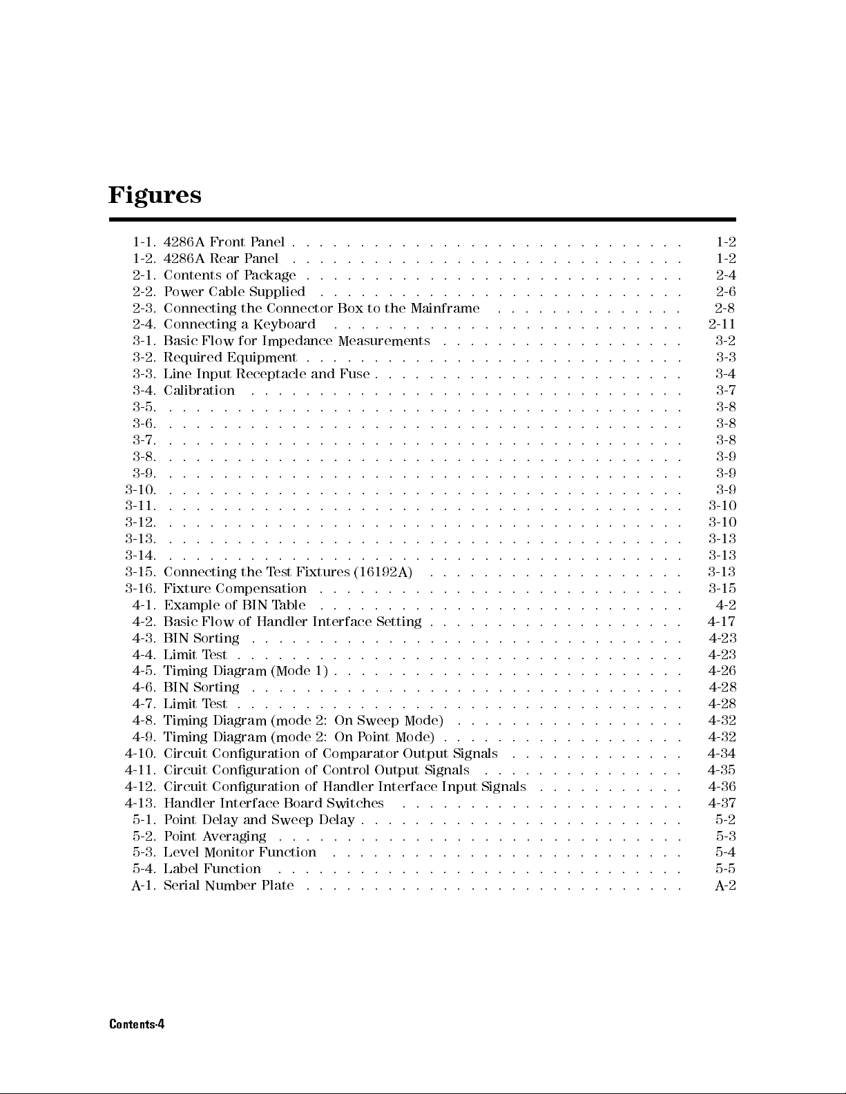
Figures
1-1. 4286A
1-2. 4286A
2-1. Contents
2-2. P
2-3. Connecting
2-4.
Connecting
3-1.
Basic
3-2.
Required
3-3.
Line
3-4.
Calibration
3-5.
.
3-6.
.
3-7. .
3-8.
.
3-9.
.
3-10.
3-11.
3-12.
3-13.
3-14.
3-15.
3-16.
4-10. Circuit Conguration of Comparator Output Signals
4-11. Circuit Conguration of Control Output
4-12. Circuit Conguration of Handler Interface Input
4-13. Handler Interface Board Switches
.
.
.
.
.
Connecting
Fixture
4-1.
Example
4-2.
Basic
4-3.
BIN
4-4.
Limit
4-5.
Timing Diagram
4-6.
BIN Sorting
4-7.
Limit T
4-8.
Timing Diagram
4-9.
Timing
5-1. P
5-2. P
5-3. Level Monitor Function
5-4. Label Function
A-1. Serial Number Plate ........ ...... ...... ..... ... A-2
Front
P
anel
.
.
.
.
.
Rear
P
anel
.
.
.
.
.
of
P
ackage
ower
Cable
Supplied
the
a
Keyboard
Flow
for
Impedance
Equipment
Input
Receptacle
.
.
.
.
.
.
.
.
.
.
.
.
.
.
.
.
.
.
.
.
.
.
.
.
.
.
.
.
.
.
.
.
.
.
.
.
.
.
.
.
.
.
.
.
.
.
.
.
.
.
.
.
.
.
.
.
.
.
.
.
.
.
.
.
.
.
.
.
.
.
.
.
the
Compensation
of
BIN
Flow
of
Handler
Sorting
T
est
est .
oint Delay and Sweep Delay .
oint A
.
.
.
.
.
..
..
Diagram
veraging ....
.
.
.
.
.
.
.
Connector
.
.
.
.
.
.
.
.
.
.
.
.
.
.
.
.
.
.
.
.
.
.
T
est
T
able
.
.
.
.
(Mode 1)
..
..
(mode 2:
(mode
.................
Box
.
.
Measurements
.
.
.
.
and
Fuse
.
.
.
.
.
.
.
.
.
.
.
.
.
.
.
.
.
.
.
.
.
.
.
.
.
.
.
.
.
.
.
.
.
.
.
.
.
.
.
.
.
.
.
.
Fixtures
.
.
.
.
.
.
Interface
..
..
..
..
..
..
.
.
.
.
.
.
On Sweep
2:
On
...... ...... ...... ..... ..
..... ..... .....
.
.
.
.
.
.
.
.
.
..
..
..
..
.
.
.
.
.
.
.
.
.
.
.
.
.
..
..
..
..
.
.
.
.
.
.
.
.
.
.
.
.
.
.
..
..
..
..
.
.
.
.
.
.
.
.
.
.
.
.
.
.
..
..
..
..
.
.
to
the
Mainframe
.
.
.
.
.
.
.
.
.
.
.
.
.
.
.
.
.
.
.
.
.
.
.
.
.
.
.
.
.
.
.
.
.
.
..
.
.
.
.
..
..
.
.
.
.
..
..
.
.
.
.
.
.
..
.
.
.
.
.
.
..
.
.
.
.
.
.
..
..
.
.
.
.
.
..
.
.
.
.
.
.
..
.
.
.
.
.
.
..
.
.
.
(16192A)
.
.
.
..
..
Setting
..
..
.
.
.
.
.
.
.
.
P
oint
...... ...... ...... .....
.
.
..
..
.
.
.
.
.
..
.
.
.
.
.
.
.
.
.
.
.
.
.
.
.
.
.
.
.
.
.
Mode) .
Mode)
.
Signals ... ..... ...... .
...
..................
.
.
.
.
.
.
.
.
.
.
.
.
.
.
..
..
..
.
.
.
.
.
.
.
.
.
.
.
.
.
..
..
.
.
.
..
..
..
.
.
.
.
.
.
.
.
.
.
.
..
..
.
.
.
.
.
.
.
.
.
..
.
.
.
.
.
.
.
.
.
.
.
.
.
.
.
.
..
.
.
.
.
.
.
.
.
.
.
..
..
.
.
.
.
.
.
.
.
..
.
.
.
.
.
.
.
.
.
.
..
.
.
.
.
.
.
.
.
.
.
..
.
.
.
.
.
.
.
.
.
.
.
.
.
.
.
.
.
.
.
.
.
.
.
.
.
.
.
.
.
.
.
.
.
.
.
.
.
.
.
.
.
.
.
.
.
.
.
.
.
.
.
.
.
.
.
.
.
.
.
.
.
.
.
.
.
.
.
.
.
.
..
.
.
.
.
.
.
.
.
.
.
.
.
.
.
.
.
.
.
.
.
.
.
.
.
.
.
.
.
.
..
..
.
.
.
.
.
.
.
.
.
.
.
.
.
.
.
.
.
.
.
.
.
.
.
.
.
.
.
.
.
.
.
.
.
.
.
.
.
.
.
.
.
.
.
.
.
.
.
..
.
.
.
.
.
.
.
.
..
..
..
.
.
.
.
.
.
..
..
..
..
..
.
.
.
.
.
.
.
.
.
.
.
..
.
.
.
.
.
.
.
.
.
.
.............
Signals ...........
...........
...... ...... .
.
.
.
.
.
.
.
.
.
.
.
.
.
.
.
.
.
.
.
.
.
.
..
.
.
.
.
.
.
.
.
.
.
.
.
..
.
.
.
.
.
.
.
.
.
.
.
.
.
.
.
.
.
.
.
.
.
.
.
.
.
.
.
.
.
.
.
.
.
.
..
..
..
.
.
.
.
.
.
.
.
.
. 2-8
.
2-11
.
.
.
.
.
.
.
.
.
.
.
3-10
.
3-10
.
3-13
.
3-13
.
3-13
.
3-15
.
.
4-17
. 4-23
. 4-23
. 4-26
.
4-28
.
4-28
. 4-32
.
4-32
4-34
4-35
4-36
4-37
. 5-3
5-4
1-2
1-2
2-4
2-6
3-2
3-3
3-4
3-7
3-8
3-8
3-8
3-9
3-9
3-9
4-2
5-2
5-5
Contents-4
Page 11
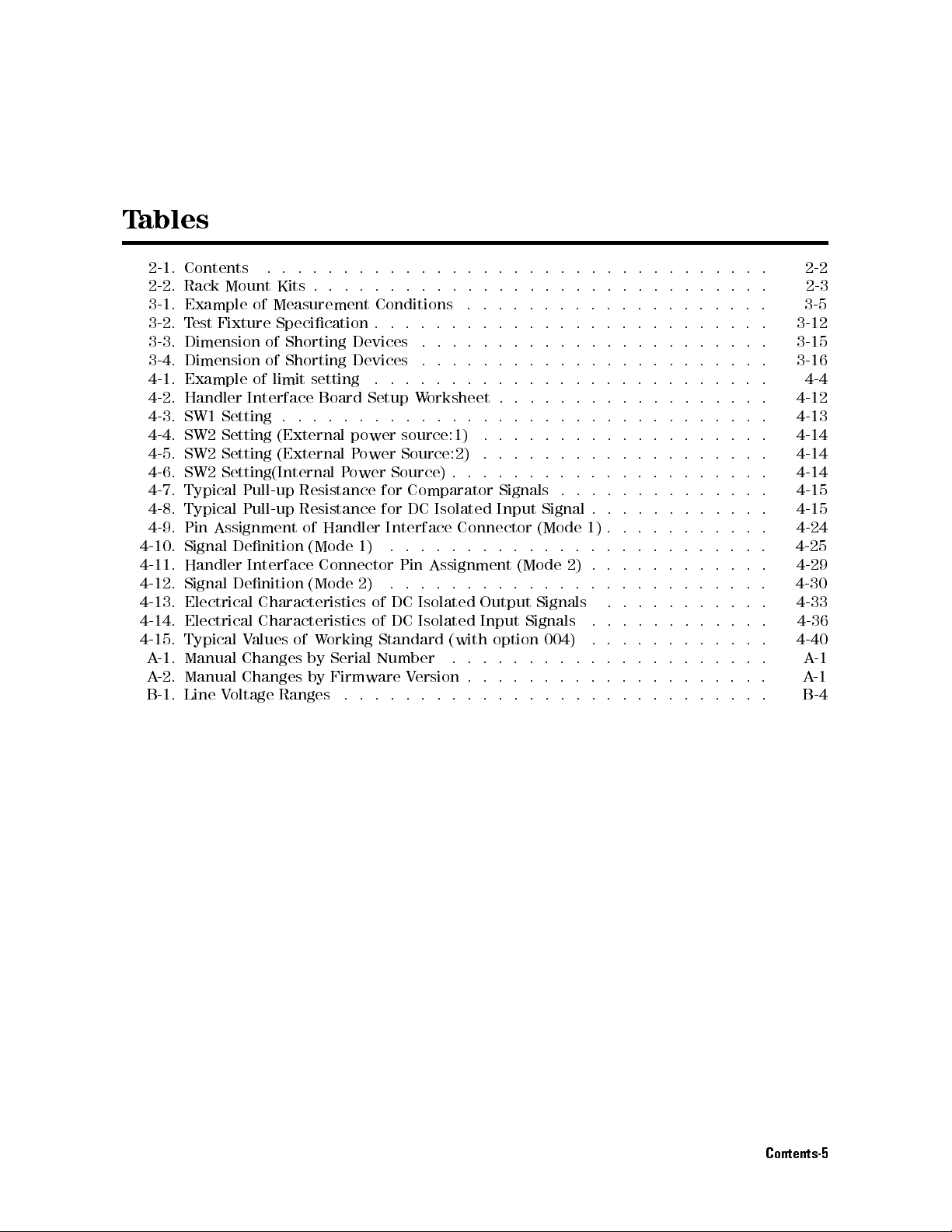
T
ables
2-1. Contents
2-2.
Rack
3-1.
Example
3-2.
T
est
Fixture
3-3.
Dimension
3-4.
Dimension
4-1.
Example
4-2.
Handler
4-3.
SW1
4-4.
SW2
4-5.
SW2
4-6. SW2
4-7.
Typical
4-8.
Typical
4-9.
Pin
Assignment
4-10.
Signal
4-11.
Handler
4-12.
Signal
4-13.
Electrical
4-14.
Electrical
4-15.
Typical
A
-1.
Manual
A
-2.
Manual
B-1.
Line
..
.
.
.
Mount
Setting
Setting
Setting
Setting(Internal P
V
Kits
of
Measurement
Specication
of
Shorting
of
Shorting
of
limit
Interface
.
(External
(External
Pull-up
Pull-up
Denition
Interface
Denition
Characteristics
Characteristics
V
alues
of
Changes
Changes
oltage
Ranges
.
.
setting
Board
.
.
.
Resistance
Resistance
of
Handler
(Mode
Connector
(Mode
W
orking
by
Serial
by
Firmware
.
.
.
.
.
.
Conditions
.
Devices
Devices
.
Setup
.
.
.
power
P
ower
ower
1)
2)
of
of
Number
..
..
.
.
.
.
.
.
.
.
.
.
.
.
.
.
W
orksheet
.
.
.
source:1)
Source:2)
Source)
for
Comparator
for
DC
Interface
.
.
.
Pin
Assignment
.
.
.
DC
Isolated
DC
Isolated
Standard
V
ersion
.
.
.
.
.
.
.
.
.
.
.
.
.
.
.
.
.
.
.
.
.
.
.
.
.
.
Isolated
Connector
.
.
.
.
.
.
(with
.
.
.
.
.
.
.
.
.
.
.
..
.
.
.
.
.
.
.
.
.
.
.
.
.
.
.
.
.
.
..
.
.
.
.
.
.
.
.
.
Signals
Input
.
.
.
..
.
Output
Input
option
.
.
.
.
.
.
.
.
.
.
.
..
.
.
.
.
.
.
.
.
.
.
.
.
..
.
.
.
.
.
.
Signal
(Mode
.
.
(Mode
.
.
Signals
Signals
004)
.
..
.
..
.
.
..
..
.
.
..
.
.
.
.
.
.
.
.
.
.
.
.
.
.
.
.
.
.
.
..
2)
.
.
.
..
.
.
..
.
..
.
.
..
.
.
.
.
.
.
.
1)
.
.
.
.
.
.
..
..
.
.
..
.
.
.
.
..
.
..
.
.
.
.
.
.
.
.
.
.
.
.
.
.
..
.
.
.
.
.
.
.
.
.
..
.
.
.
.
.
.
.
.
..
..
.
.
.
.
.
.
.
.
.
.
.
.
.
.
.
..
.
.
..
..
..
..
..
..
.
.
.
.
.
.
.
.
.
.
.
.
.
.
.
.
.
.
.
.
.
..
..
.
.
.
.
.
.
.
.
.
.
.
.
..
.
.
..
..
.
.
..
.
.
.
.
.
.
.
.
..
..
.
.
.
.
.
.
.
.
.
.
.
.
.
.
.
.
.
.
.
.
.
.
.
..
.
.
.
.
.
.
.
.
.
.
.
..
.
..
..
..
..
.
..
.
.
.
.
.
.
.
.
.
.
.
.
.
.
.
.
.
..
.
.
.
.
..
.
.
.
.
.
.
.
.
.
.
.
.
.
.
..
..
..
. 4-24
.
.
.
. 4-29
.
.
.
.
.
.
.
.
.
.
.
.
. B-4
2-2
2-3
3-5
3-12
3-15
3-16
4-4
4-12
4-13
4-14
4-14
4-14
4-15
4-15
4-25
4-30
4-33
4-36
4-40
A
A
-1
-1
Contents-5
Page 12

Page 13
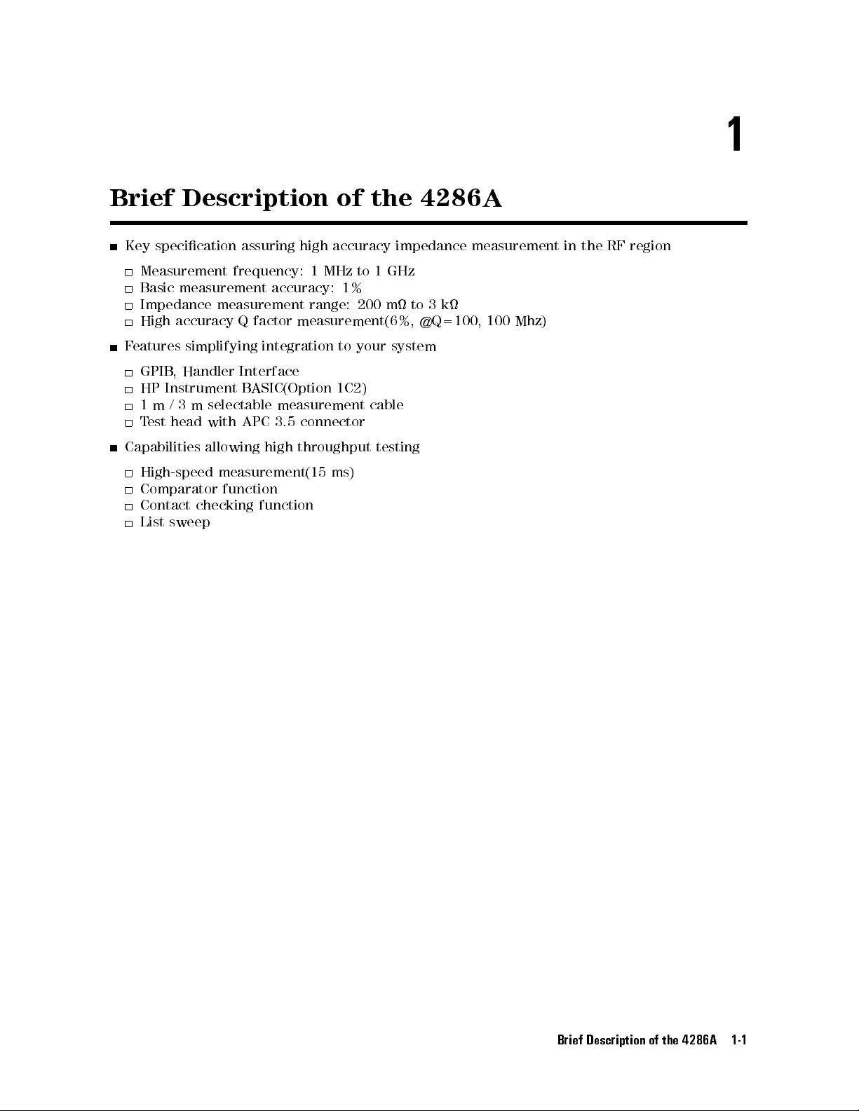
1
Brief
Description of
Key specication
Measurement frequency:
Basic measurement
Impedance measurement
High
accuracy
F
eatures
GPIB
HP
1m
T
simplifying
,
Handler
Instrument
/
3
m
est
head
selectable
with
Capabilities allowing
High-speed
Comparator
Contact
List
sweep
measurement(15
function
checking
assuring
accuracy:
Q
factor
measurement(6%,
integration
Interface
B
ASIC(Option
measurement
APC
3.5
high
throughput
function
high
accuracy
1
MHz
1%
range:
to
1C2)
connector
ms)
the 4286A
impedance
to
1
GHz
200
m
to
3
k
@Q=100,
your
system
cable
testing
measurement
100
Mhz)
in
the
RF
region
Brief Description of the 4286A 1-1
Page 14
Front and
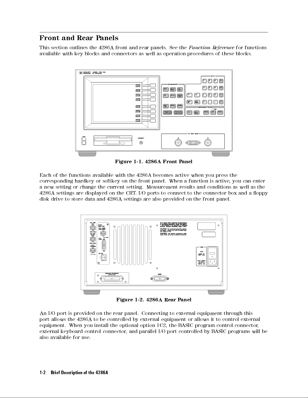
This
section
available
outlines
with
Rear P
the
key
blocks
anels
4286A front
and connectors
and rear
as well
panels.
as operation
See the
Function R
eference
procedures of
for
functions
these blocks
.
Each
of
the
functions
corresponding
a
new
setting
4286A
disk
settings
drive
to
hardkey
or
change
are
store
available
or
the
displayed
data
and
Figure 1-1.
with
softkey
current
on
4286A
on
the
the
the
setting.
CRT
settings
4286A Front
4286A
front
Measurement
.
I/O
ports
are
Figure 1-2. 4286A Rear P
becomes
panel.
to
also
provided
Panel
active
When
results
connect
anel
when
a
function
to
the
on
the
you
and
conditions
connector
front
is
press
active
panel.
the
,you
can enter
as
well
box and
as
a
oppy
the
An
I/O port is provided on the rear panel. Connecting to external equipment through this
port allows
the 4286A to be controlled by external equipment or allows it to control external
equipment. When you install the optional option 1C2, the BASIC program control connector,
external keyboard control connector, and parallel I/O port controlled by BASIC programs will be
also available for use.
1-2 Brief Description of the 4286A
Page 15
2
Installation
This chapter
setting up
Incoming
W
arning
provides
your
4286A
Inspection
T
o
avoid
are
signs
example,
Inspect
is
completeness
of
mechanical
nearest
material
oce
The
voltage
the
the
damaged,
the
shipment
Agilent
shows
.
Keep
line voltage
of the
Line V
shipping
it
should
and
the
should
damage
or
T
echnologies
signs
the
shipping
selector
country
oltage Setting"
and Set
the
information
.
hazardous
of
shipping
covers
container
be
kept
for
until
4286A has
be
as listed
defect,
or
oce
of
unusual
materials
is
set
at
of
destination.
in
Appendix
Up Guide
necessary
electrical
damage
,
panel,
damage
the
or
.
contents
been checked
in
T
able
if the
4286A
.
If the
shipping
stress
,
notify the
for
the
carrier's
the
factory
If
you
B.
for
shock,
to
any
display)
If
the
shipping
of
the
mechanically
2-1
.
If
the
does
container
carrier
to
correspond
want
to
performing
do
not
portion
container
shipment have
and
contents
not
pass
the
is
as
well
inspection.
to
change
the
an
incoming
turn
on
of
the
or cushioning
electrically
are
incomplete
power-on
damaged,
as
the
the
most
line
inspection
the
4286A
outer
enclosure
been checked
.
The
,
if
selftests
or
the
Agilent
T
echnologies
commonly
voltage
,
see
and
when
(for
material
for
contents
there
is
,
notify
cushioning
used
line
\Changing
there
the
Installation and Set Up Guide 2-1
Page 16
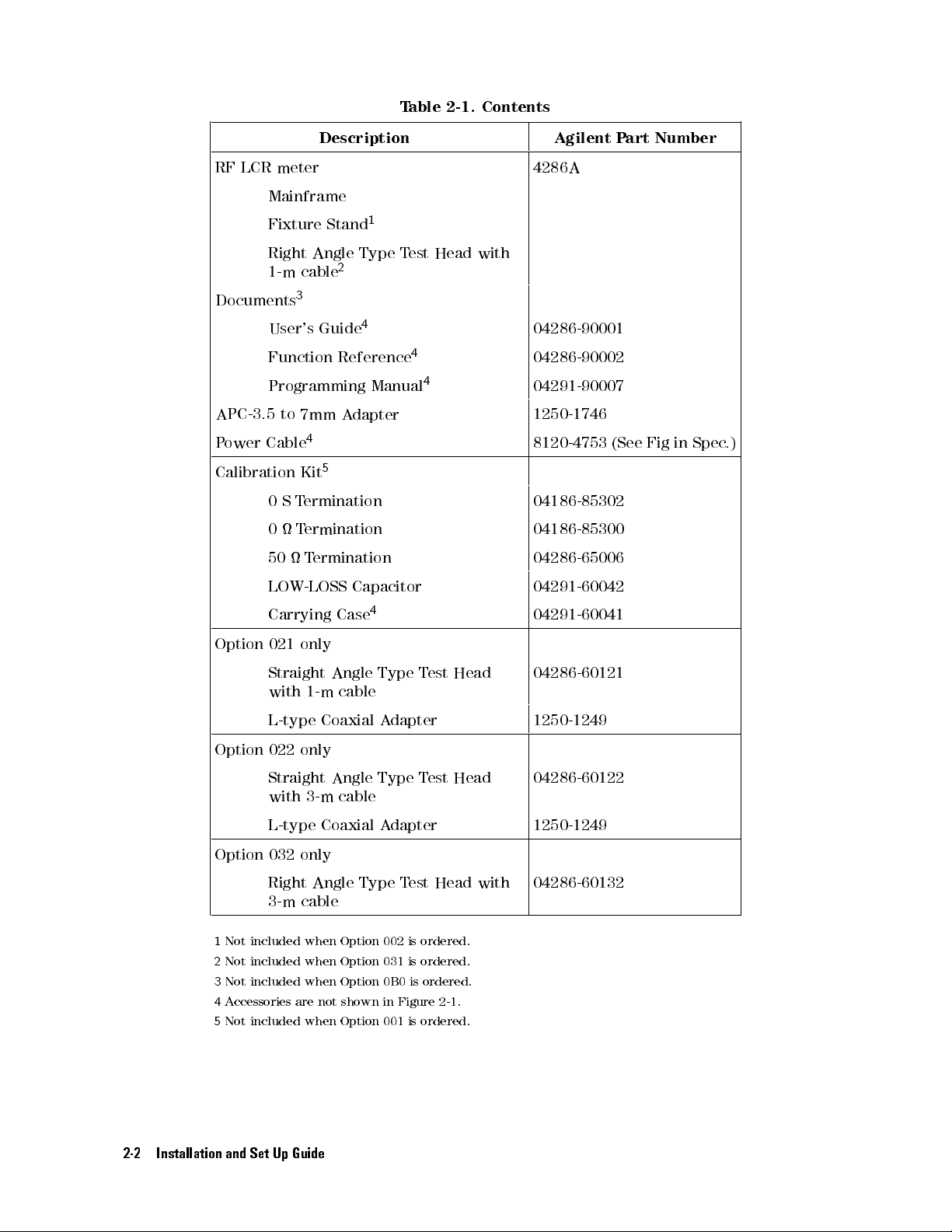
T
able 2-1.
Contents
RF
LCR meter
Mainframe
Fixture
Right
1-m
cable
Documents
3
User's Guide
Function
Programming
APC-3.5
P
ower
to
Cable
7mm
4
Calibration Kit
0
S
T
ermination
0
T
ermination
50
T
LOW-LOSS Capacitor 04291-60042
Carrying
Description Agilent P
4286A
1
Stand
Angle
Type
T
est
Head
with
2
4
Reference
Manual
A
dapter
4
4
04286-90001
04286-90002
04291-90007
1250-1746
8120-4753
5
04186-85302
04186-85300
ermination
4
Case
04286-65006
04291-60041
art Number
(See
Fig
in
Spec
.)
Option
Option 022
021
only
Straight
with
1-m
L-type
only
Straight
with
3-m
L-type
Angle
Type
cable
Coaxial
Angle
Type
cable
Coaxial A
A
dapter
dapter
T
T
est
est
Option 032 only
Right Angle Type T
est Head with
3-m cable
1
Not included when Option 002 is ordered.
2
Not included when Option 031 is ordered.
3
Not included when Option 0B0 is ordered.
4
Accessories are not shown in Figure 2-1.
5
Not included when Option 001 is ordered.
Head
Head
04286-60121
1250-1249
04286-60122
1250-1249
04286-60132
2-2 Installation and Set Up Guide
Page 17
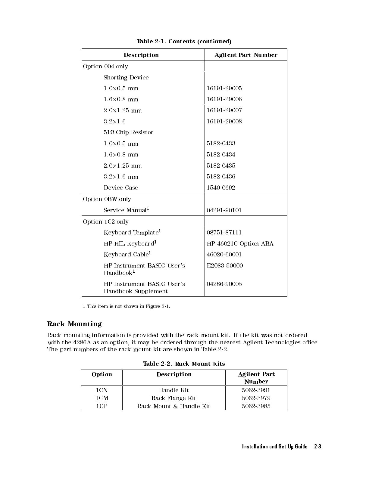
T
able 2-1.
Contents (continued)
Option
Option
Option
Description Agilent P
004
only
Shorting
1.0
2
0.5
1.6
2
0.8
2.0
2
1.25
3.2
2
1.6
51
Chip
1.0
2
0.5 mm
1.6
2
0.8
2.0
2
1.25
3.2
2
1.6
Device
0BW
Case
only
Service
1C2
only
Keyboard
HP-HIL
Keyboard
Device
mm
mm
mm
Resistor
mm
mm
mm
Manual
1
T
emplate
Keyboard
Cable
art Number
16191-29005
16191-29006
16191-29007
16191-29008
5182-0433
5182-0434
5182-0435
5182-0436
1540-0692
04291-90101
1
1
1
08751-87111
HP
46021C
46020-60001
Option
AB
A
E2083-90000
04286-90005
Rack
1
This item
Mounting
HP
Instrument
Handbook
HP
Instrument
Handbook
is
not
shown
B
ASIC
1
BASIC
Supplement
in
Figure
User's
User's
2-1
.
Rack mounting information is provided with the rack mount kit. If the kit was not ordered
with the 4286A as an option, it may be ordered through the nearest Agilent T
The part
numbers of the rack mount kit are shown in T
Table 2-2. Rack
Mount Kits
able 2-2.
echnologies oce
Option Description Agilent Part
Number
1CN Handle Kit 5062-3991
1CM Rack Flange Kit 5062-3979
1CP Rack Mount & Handle Kit 5062-3985
.
Installation and Set Up Guide 2-3
Page 18
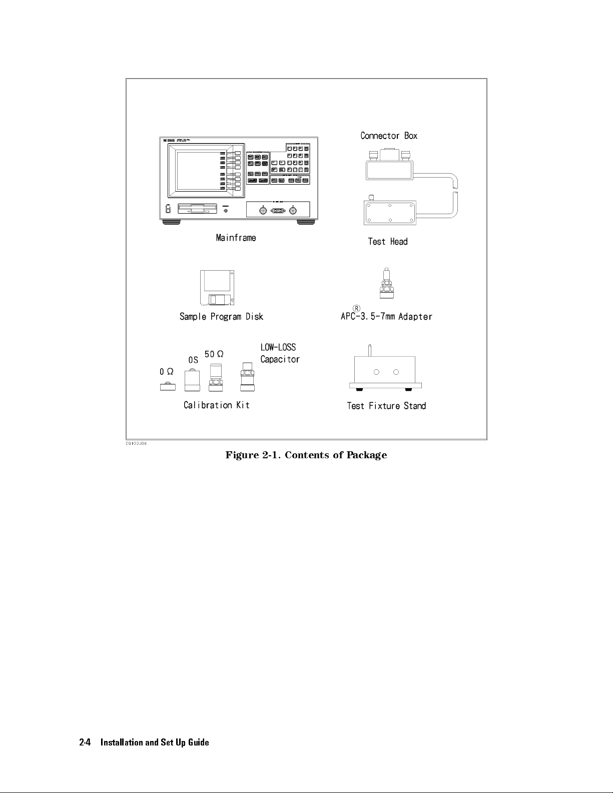
2-4 Installation and Set Up Guide
Figure
2-1.
Contents
of
P
ackage
Page 19
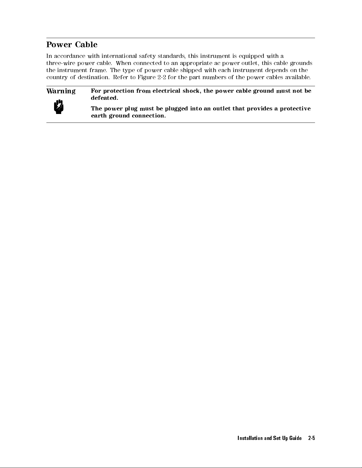
Power
In
accordance
three-wire
the
instrument
country
W
of
arning
Cable
with
power
cable
frame
destination.
F
or
defeated.
The
earth
international
.
When connected
.
The type
Refer
to Figure
protection
power
plug
ground
connection.
safety standards
to an
of power
cable shipped
2-2 for
from
electrical
must
be
plugged
, this
instrument is
appropriate ac
with each
the part
shock,
numbers of
the
into
an
power outlet,
instrument depends
the power
power
outlet
cable
that
equipped with
this cable
cables available
ground
provides
a
grounds
on the
must
not
a
protective
.
be
Installation and Set Up Guide 2-5
Page 20
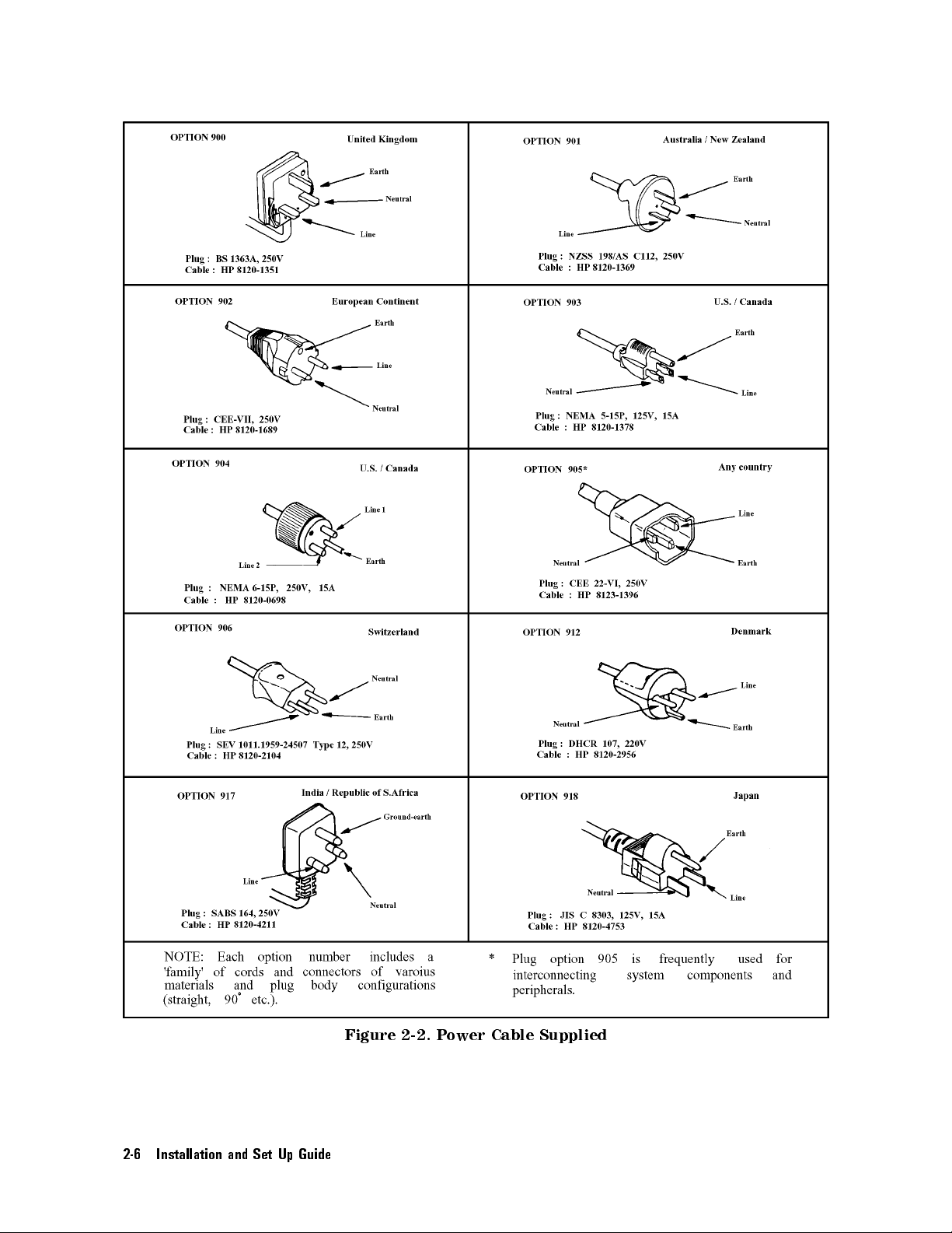
2-6 Installation and Set Up Guide
Figure 2-2. Power Cable Supplied
Page 21
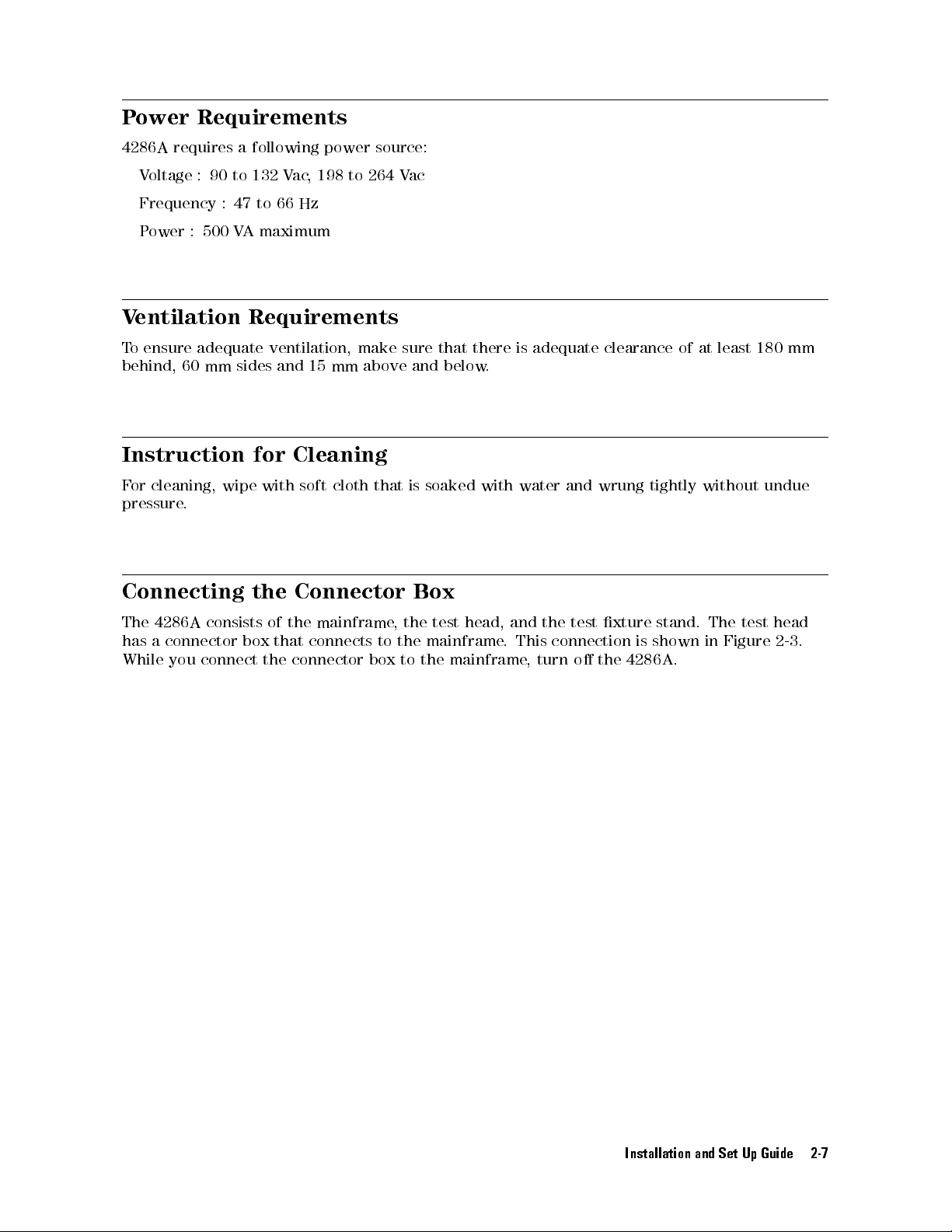
Power
Requirements
4286A
requires
V
oltage
:
Frequency
P
ower
:
500
90
:
Ventilation
T
o
ensure
behind, 60
adequate
mm sides
Instruction
F
or
cleaning,
pressure
wipe with
.
Connecting
a
following
to 132
47
to
VA
maximum
66 Hz
power source:
Vac
,198
to 264
Requirements
ventilation, make
and 15
for
mm
Cleaning
soft cloth
the
Connector
above
that is
Vac
sure that
and
below
soaked with
Box
there is
.
adequate
water
and
clearance
wrung
of
tightly
at
least
without
180
undue
mm
The
has
a
While
4286A
connector
you
connect
consists of
box
the
the
mainframe
that
connects
connector
to
box
,
the
the
mainframe
to
the
test
head,
mainframe
.
and
This
,
turn
the
test
connection
o
the
xture
is
4286A
stand.
shown
.
The
in
test
Figure
head
2-3
.
Installation and Set Up Guide 2-7
Page 22
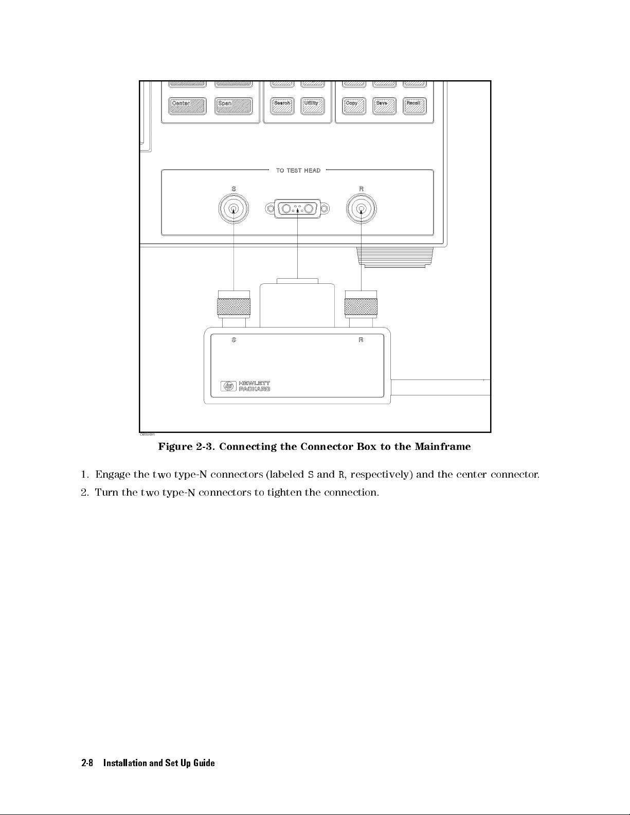
Figure 2-3.
Connecting
the
Connector
Box
to
the
Mainframe
1. Engage
2.
Turn
the two
the
two
type-N connectors
type-N
connectors
2-8 Installation and Set Up Guide
(labeled
to
tighten
S
and
the
connection.
R
,
respectively)
and
the
center
connector
.
Page 23
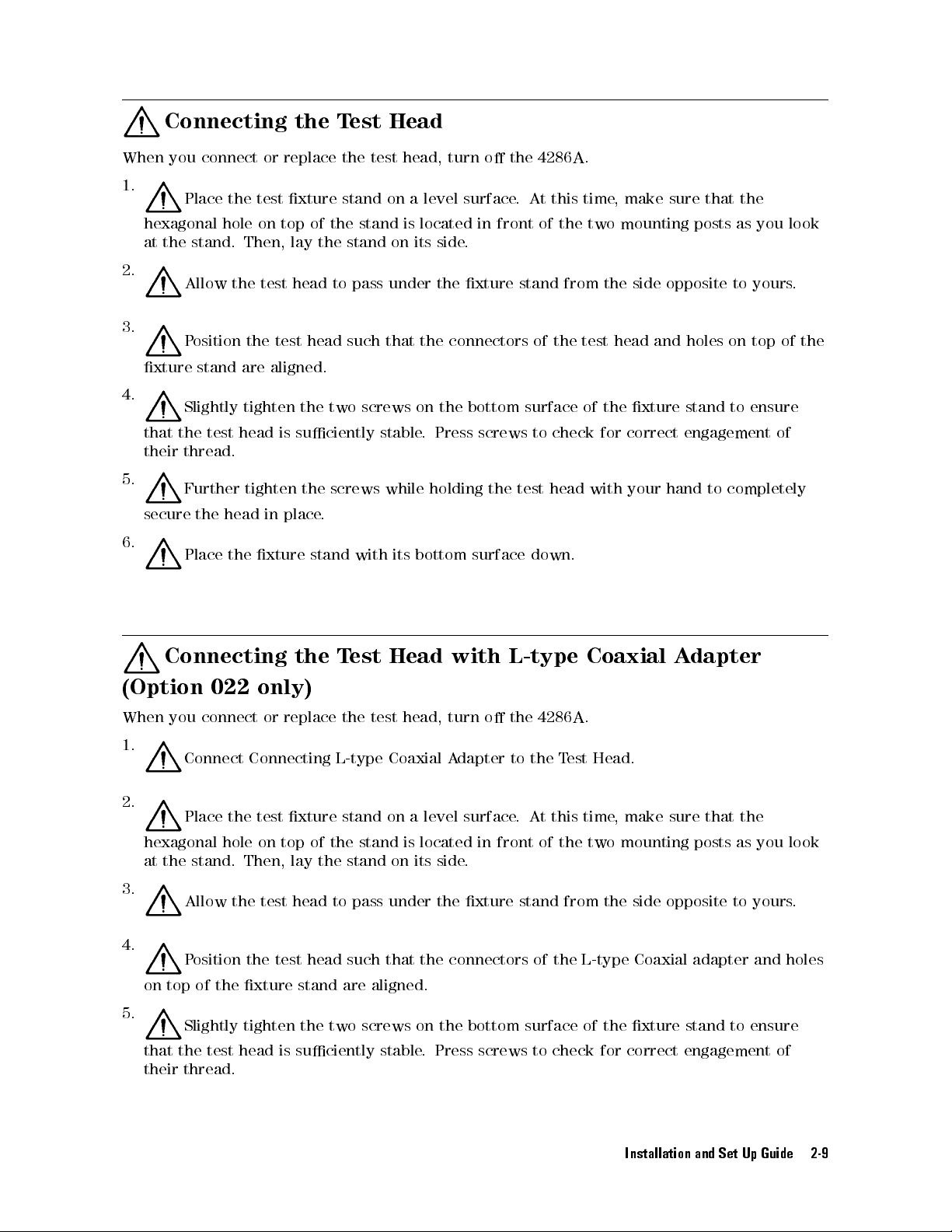
Connecting the
When
you
connect
or
replace
Test
the
Head
test
head,
turn
o
the
4286A
.
1.
hexagonal
at
2.
3.
xture
4.
that
their
5.
secure
6.
Place the
hole on
the stand.
Allow
P
osition
stand
the
are
Slightly
the
test
head
thread.
Further tighten
the
head
Place
the
test xture
top of
Then, lay
test
head
the
test
aligned.
tighten
is
suciently
in
place.
xture
stand on
the stand
the stand
to
pass
head
such
the
two
screws
the screws
stand
with
a level
is
located
on
its
side
under
that
stable
the
the
connectors
on
the
.
Press
while holding
its
bottom
surface.
in
front
.
xture
bottom
screws
the test
surface
At this
of
stand
of
the
surface
to
check
head
down.
time
the
two
from the
test head
of
the
for
with
,
make
sure
mounting
side opposite
and holes
xture
correct
your
hand
that
the
posts
as
you
to yours
on top
stand
to
ensure
engagement
to
completely
of
of
look
.
the
Connecting
(Option
When
you
022
connect
the
only)
or
replace
T
the
est
Head
test
head,
with
turn o
L-type
the 4286A
Coaxial
.
A
dapter
1.
Connect
Connecting
L-type
Coaxial
A
dapter
to
the T
est Head.
2.
Place
the
test
xture
hexagonal
hole
on
top
at the stand. Then, lay the stand on its
stand
of
the stand
on
a
level
is
located
side.
surface
in
front
.
At
this time
of
the
two
, make
mounting
sure that
posts
as
3.
Allow the test head
to pass under the xture stand from the side opposite to yours
4.
Position the
test head such that the connectors of the L-type Coaxial adapter and holes
on top of the xture stand are aligned.
5.
Slightly tighten the two screws on the bottom surface of the xture stand to ensure
that the test head is suciently stable. Press screws to check for correct engagement of
their thread.
the
you look
.
Installation and Set Up Guide 2-9
Page 24
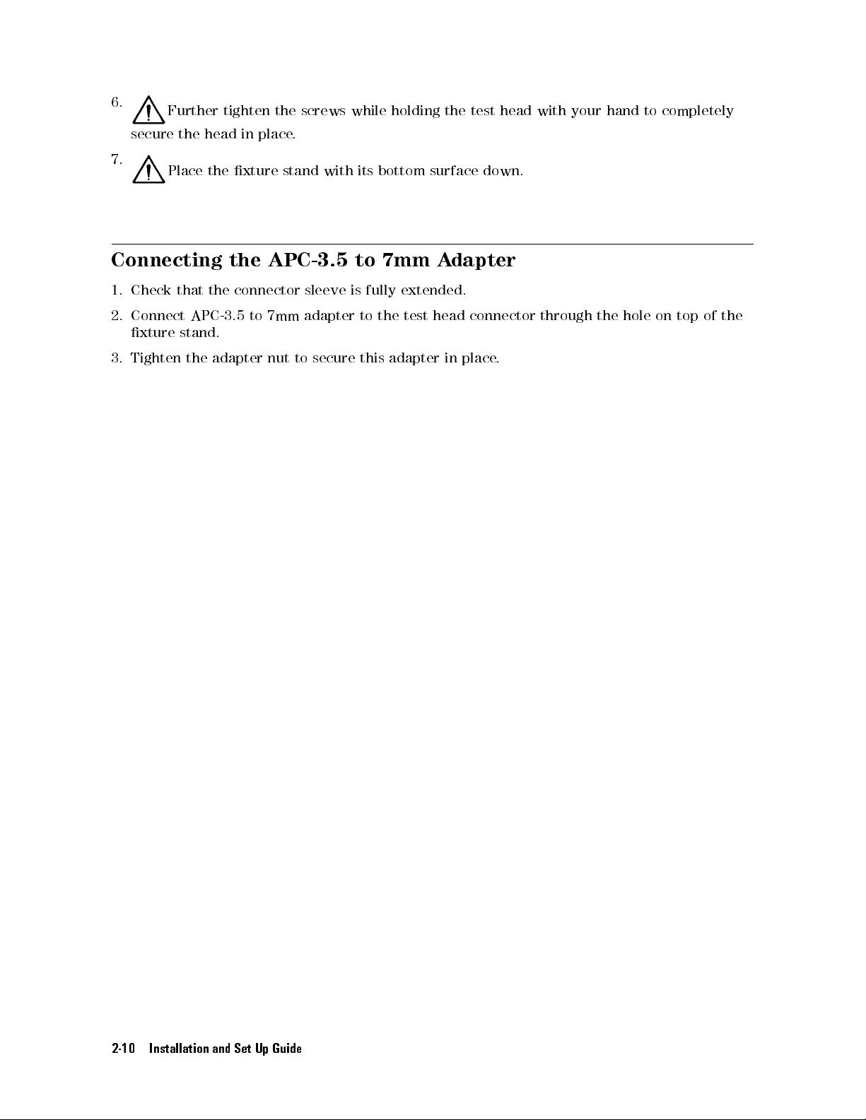
6.
secure the
Further
head in
tighten
place.
the
screws while
holding the
test head
with your
hand to
completely
7.
Place
the
Connecting
1. Check
2. Connect
that the
APC-3.5 to
xture stand.
3. Tighten
the
xture
the
stand
APC-3.5
connector sleeve
7mm adapter
adapter
nut
to
with
secure
its
to
is
fully
to
this
bottom
7mm
extended.
the
test
adapter
surface down.
A
dapter
head
connector
in
place
.
through
the
hole
on
top
of
the
2-10 Installation and Set Up Guide
Page 25
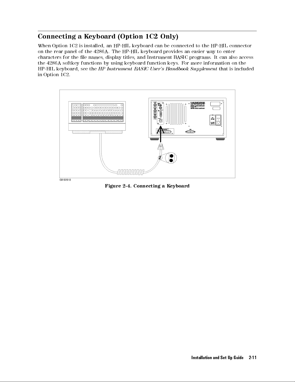
Connecting a
When
Option
on
the
rear
characters
the
4286A
HP-HIL
in
Option
1C2
panel
for
the
softkey
keyboard,
1C2.
Keyboard
is
installed, an
of the
le
4286A.
names,
functions
see
the
HP Instrument
(Option 1C2
HP-HIL keyboard
The HP-HIL
display titles
by using
keyboard function
Only)
can be
keyboard provides
, and
Instrument B
BASIC
User's Handbook
connected to
an easier
ASIC programs
keys.
For
the HP-HIL
way to
.It
enter
can also
more information
Supplement
that
connector
access
on the
is
included
Figure
2-4.
Connecting
a
K
eyboard
Installation and Set Up Guide 2-11
Page 26

Page 27
3
Basic
Measurement Procedures
This chapter
with
the
4286A
the
At
4286A
the
,
end
impedance
of
measurement
Calibration
Setting
electrical
Correction
List sweep
provides a
by
following
the
quick
results:
length
of
test
xture
quick
of
inductors
start
of
start
guide
these
procedures
are
procedures
test
xture
of
the
.
measured
,
you
will
4286A
In
this
as
have
.
New
chapter
examples
learned
users
,
to
.
how
can
help
quickly
you
to
get
learn
the
become
how
to use
following
familiar
Basic Measurement Procedures 3-1
Page 28
Measurement Outline
This
chapter
describes
how
to measure
the impedance
of a
100 nH
inductor as
an example
.
Measurement
P
arameter
Frequency
OSC
level
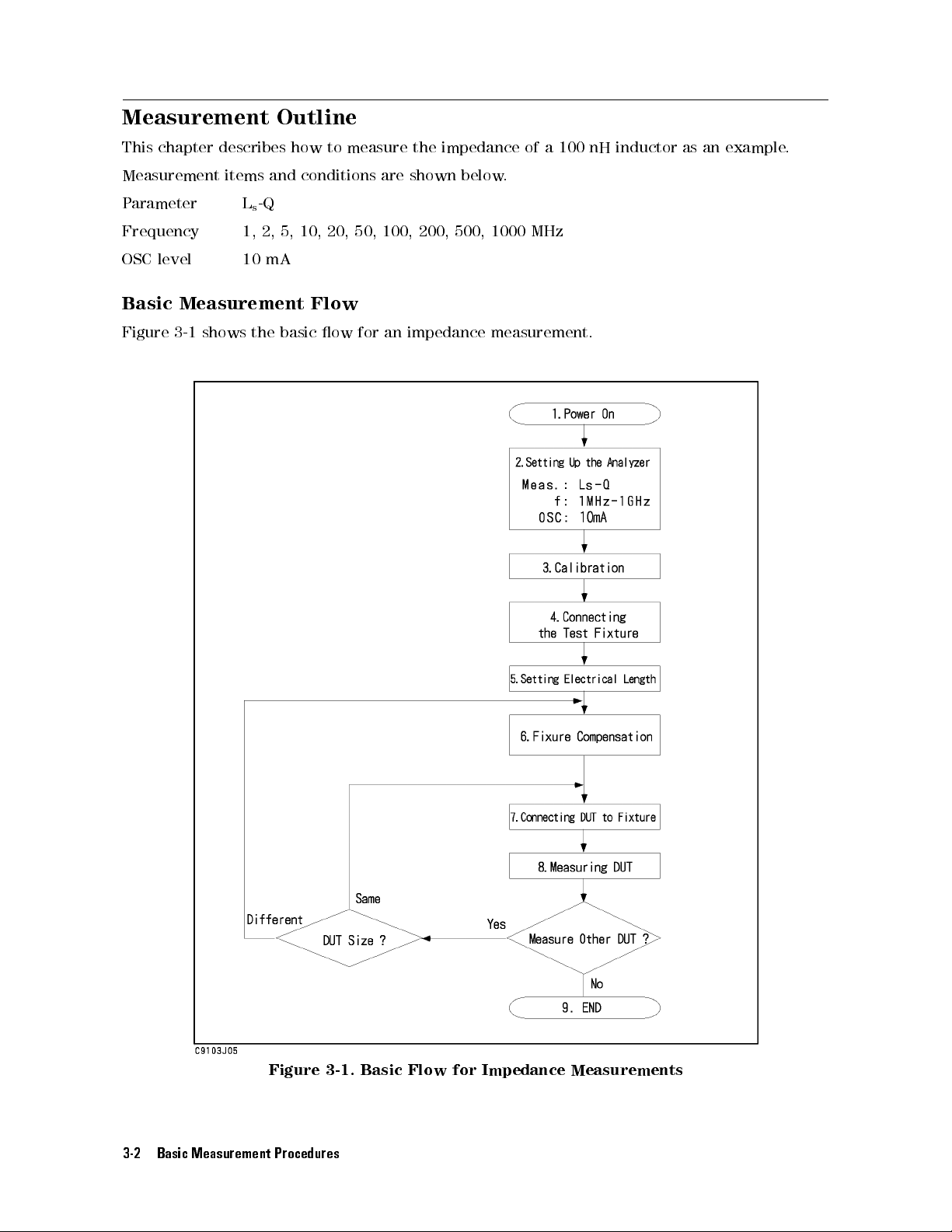
Basic
Figure
Measurement
3-1
shows
items
L
1,
10
the
and
conditions
-Q
s
2,
5,
10, 20,
are shown
50, 100,
below.
200, 500,
1000 MHz
mA
Flow
basic
ow
for
an
impedance
measurement.
Figure 3-1. Basic Flow for Impedance Measurements
3-2 Basic Measurement Procedures
Page 29
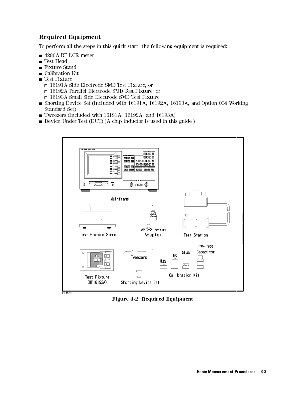
Required
T
o
perform
Equipment
all
the
steps
in
this
quick
start,
the following
equipment is
required:
4286A
T
Fixture
est
RF
Head
Stand
Calibration
T
est
Fixture
16191A
16192A
16193A
Shorting
Standard
Tweezers
Device
Under
LCR
meter
Kit
Side
Electrode
P
arallel
Small
Device
Set)
(Included
T
est
Electrode
Side
Electrode
Set
(Included
with
(DUT) (A
SMD
T
est
SMD
SMD
with
16191A
, 16192A
chip inductor
Fixture,
T
est Fixture
T
est Fixture
16191A
,and
or
,or
, 16192A
16193A)
is used
, 16193A
in
this
, and
guide
Option 004
.)
W
orking
Figure 3-2. Required Equipment
Basic Measurement Procedures 3-3
Page 30
1. P
ower ON
V
erify
the
connector
If
they
have
not
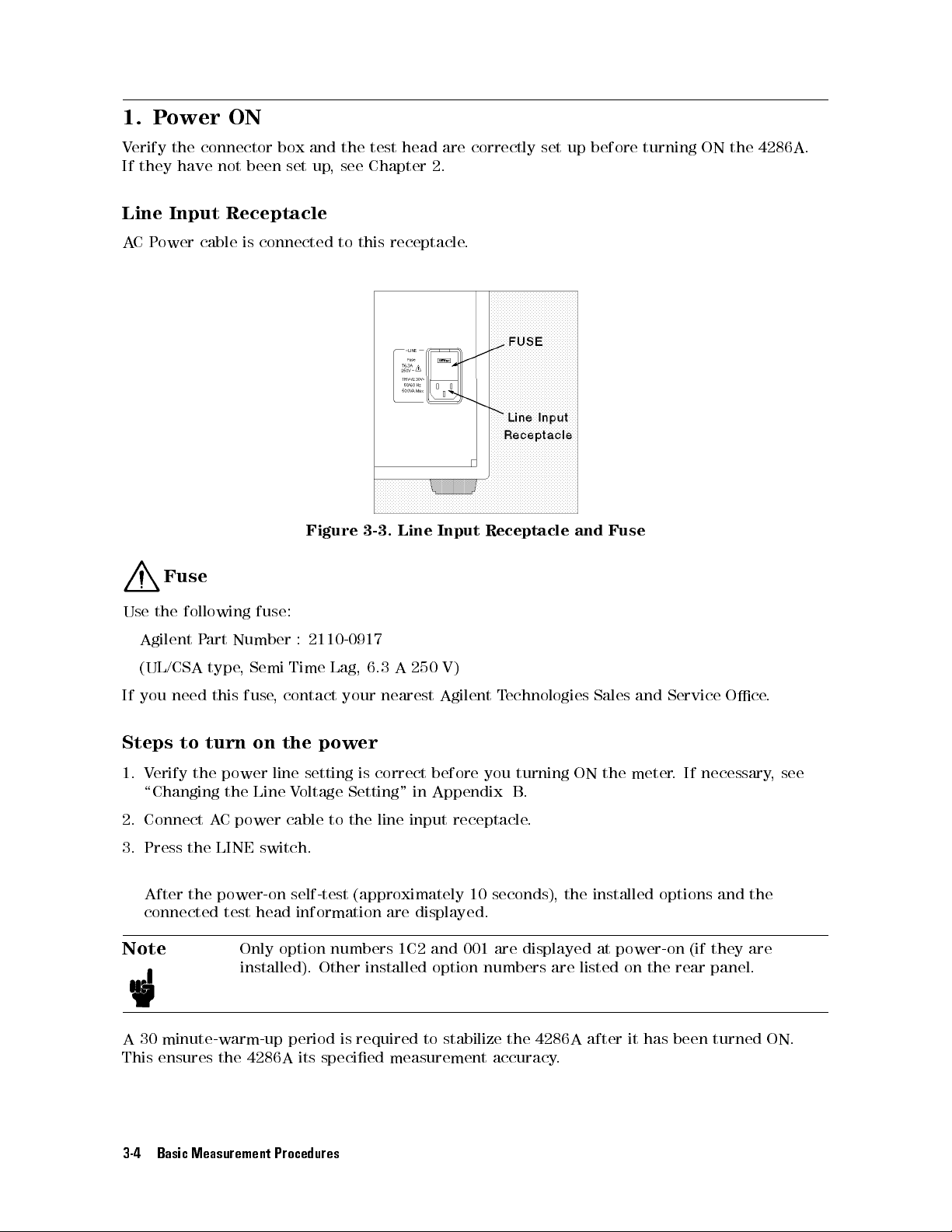
Line
Input Receptacle
A
CP
ower cable
box and
been set
up,
is connected
the test
head are
see Chapter
to
this
receptacle
correctly set
2.
.
up before
turning ON
the 4286A
.
Figure 3-3.
Line
Input
Receptacle
and
Fuse
Fuse
Use
the
following
Agilent
(UL/CSA
If
you
need
Steps
1.
V
erify
to
\Changing
2. Connect
P
art
type
turn
the
AC
fuse:
Number
,
Semi
this
fuse
on the
power
the
Line
power cable
:
Time
,
contact
line
V
oltage
2110-0917
Lag,
your
power
setting
is
Setting"
to the
6.3
A
250
nearest
correct
line input
V)
Agilent
before
in
Appendix
receptacle.
T
echnologies
you turning
B.
Sales
ON the
and
meter.
Service
If necessary
3. Press the LINE switch.
After the power-on self-test (approximately 10 seconds), the installed options and the
connected test head information are displayed.
Note
Only option numbers 1C2 and 001 are displayed at power-on (if they are
installed). Other installed option numbers are listed on the rear panel.
Oce
.
,
see
A 30 minute-warm-up period is required to stabilize the 4286A after it has been turned ON.
This ensures the 4286A its specied measurement accuracy.
3-4 Basic Measurement Procedures
Page 31
2. Setting
up the
4286A
Before
requirements
measurements
T
up
2-1.
Select
1.
2.
2-2.
you
o
set
up
procedures
Setting
parameters
Press
Press
selected.
Creating
the
4
Meas
NN
NN
N
N
N
Ls-Q
start
N
N
N
.
This
.
4286A
are
up
5
.
N
N
N
N
.
The
the
measurement, you
section
,
available
for
to
NN
a
sweep
press
L
T
able
Range
OSC
satisfy
NN
N
N
N
N
N
N
N
N
Ls-Q
provides the
the front
on the
-Q
s
3-1.
Level
the conditions
N
N
softkey
table
must set
set up
panel keys
MEASUREMENT Block.
Frequency
Example
label
becomes
up the
procedures for
as shown
Characteristics
of
Measurement
1MHz,
20MHz, 50MHz,
above
.
4286A to
below
2MHz,
100MHz, 200MHz,
500MHz,
10
F
ollow
the
underlined,
t your
-Q
frequency
L
s
.
All
keys
Measurements
Conditions
5MHz,
10MHz,
1GHz
mA
procedures
showing
measurement
characteristics
necessary
below
.
NN
NN
N
N
N
N
N
N
Ls-Q
that
for
this
set
N
N
N
N
has
been
Create
1.
2.
3. Press
4.
5.
6.
2-3. Setting the OSC level
Set the OSC signal level applied to the DUT
Hints
a
sweep
Press
4
Sw
eep
N
N
N
N
N
N
N
N
N
N
EDIT
Press
5
,
4
2
N
N
N
N
N
N
N
N
N
N
SEGMENT
Press
Repeat steps
segments
of
a
segment
N
N
N
N
N
N
N
N
N
NN
LIST
Press
Press
4
Source
NNNNNNNNNNNNNNNNNNNN
Press
AMPERE
Press
415,405
table
to
set
list sweep
5
.
Setup
N
N
N
N
N
N
N
N
N
N
N
N
N
N
N
N
N
N
N
N
N
N
N
N
NN
LIST
then
4
M/
N
N
N
N
N
N
N
NN
NN
N
N
N
N
DONE
2 through
to
5,
10,
available
NN
NN
NN
NN
NN
N
N
N
N
DONE
5
.
to set the OSC level as current.
, and then
Use
value changes in steps of 1, 2, 5, and 10 with these keys.
N
N
N
ADD
5
N
N
N
N
N
N
N
N
N
N
20,
N
N
N
N
to
4*5or4+5
N
to
to
set the
N
N
N
to
complete
4to
50,
at
power-on
complete
4
5
k/m
create
create
100,
to set the OSC level to 10 mA.
conditions
an
additional
measurement
the
segment
8
additional
200,
500,
has
the
table creation
to quickly increase or decrease the value to be entered. The
.
F
ollow
the
procedures
segment.
frequency
setting.
segments
and
1000
automatically
step.
.
Follow the procedures below
(=1G)
been
of
.
the
Set
MHz,
set
the
additional
respectively
to
below
segment
frequency
1
MHz.)
.
.
.
of
each
(The
to
2
MHz.
of
these
frequency
Basic Measurement Procedures 3-5
Page 32
To
delete the
pressed
NN
N
N
N
N
N
N
N
N
N
N
N
NN
NN
SEGMENT
T
o start
N
N
N
N
N
N
N
N
N
N
NN
NN
NN
SEGMENT
number
Y
ou
are
value you
4
5
,
or enter
M/
NN
NN
NN
NN
NN
N
N
N
N
N
N
N
N
N
N
N
DONE
.
the segment
NN
NN
NN
NN
N
N
N
N
N
N
N
N
N
N
N
NN
N
QUIT
using
numeric
now
ready
have
a new
condition setting
N
N
then
SEGMENT
and
keys
to
specify
entered,
value
N
N
N
N
N
N
N
N
NN
and
the
NN
NN
NN
NN
NN
N
.
5
4
x1
frequency
simply
if
you
all over
Next,
.
Finally
press
have
again, rst
specify
,
press
for
4
Back Space
already
the
N
N
N
N
N
N
N
EDIT
the
selected
pressed
press
desired
N
N
N
N
NN
N
and
5
if
you have
4
M/
segment
N
N
N
SEGMENT
then
segment.
not
5
but
not
N
N
N
N
N
N
N
N
NN
NN
NN
N
N
N
N
N
N
.
3-6 Basic Measurement Procedures
Page 33
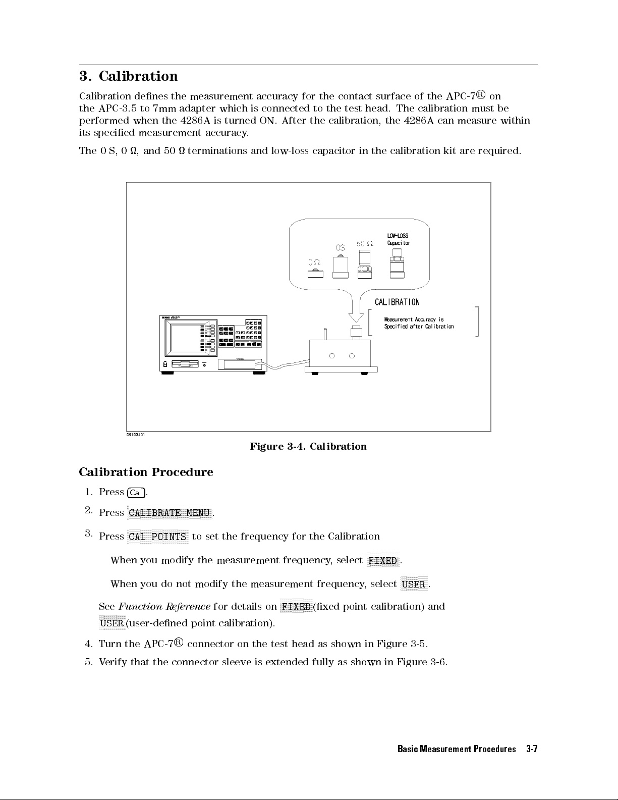
3. Calibration
Calibration
the
APC-3.5
performed
its
specied
The
0
S,
0
when
,
denes
to
7mm
the
measurement
and
50
the
measurement
adapter
4286A
accuracy
terminations
which
is
turned
accuracy
is
connected
ON.
.
and
After
low-loss
for
the
to
the
the
capacitor
contact
test
head.
calibration,
in the
surface
of
The calibration
the
4286A
calibration kit
the
APC-7
can measure
are required.
R
on
must be
within
Figure
Calibration
1.
Press
2.
Press
3.
Press
Procedure
5
.
4
Cal
N
N
N
N
N
N
N
N
NN
NN
NN
NN
N
N
N
N
N
N
N
N
N
CALIBRATE
NN
NN
NN
NN
NN
N
N
N
N
N
N
N
N
N
N
N
N
N
NN
CAL POINTS
N
N
N
NN
NN
N
N
N
N
N
N
MENU
NN
N
NN
NN
NN
NN
N
N
to set
.
the frequency
When you modify the measurement
When you do not modify the measurement frequency
3-4.
Calibration
for the
Calibration
frequency, select
NNNNNNNNNNNN
FIXED
, select
NNNNN
.
NNNNNNN
USER
NNNNNNN
.
NNNNNNNNNNNNNNNNN
See
Function R
NNNNNNNNNN
NNNN
USER
(user-dened point
4. Turn the APC-7
eference
for details on
calibration).
R
connector on the test head
FIXED
(xed point calibration) and
as shown in Figure 3-5.
5. Verify that the connector sleeve is extended fully as shown in Figure 3-6.
Basic Measurement Procedures 3-7
Page 34
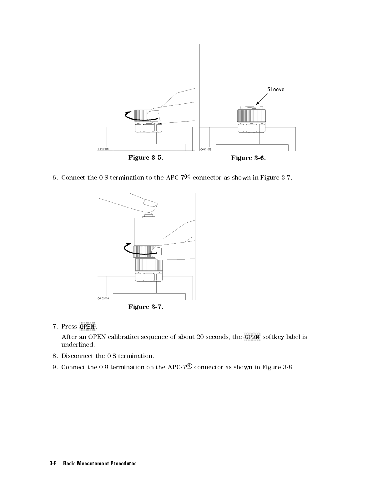
6.
Connect
the
0
S
termination
Figure
to
3-5.
the
APC-7
R
connector
Figure
as
shown
3-6.
in
Figure
3-7
.
7.
Press
After an
N
N
N
N
N
N
N
N
OPEN
N
N
N
N
N
N
.
OPEN
Figure
calibration
3-7.
sequence
underlined.
8. Disconnect the 0 S termination.
9. Connect the 0 termination on the
3-8 Basic Measurement Procedures
of
about
APC-7
N
N
N
N
NN
NN
NN
NN
NN
OPEN
20
seconds
R
connector as shown in Figure 3-8.
,
the
softkey
label
is
Page 35
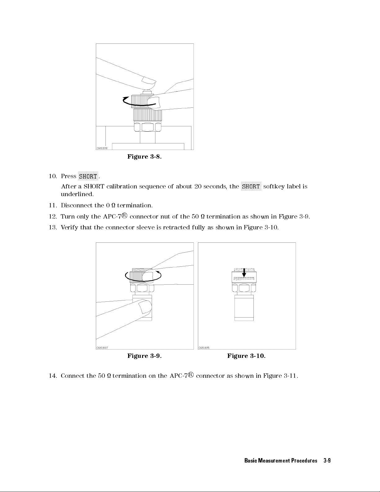
10.
Press
After
underlined.
11.
Disconnect
12.
Turn
13.
V
erify
N
N
N
N
N
N
N
N
SHORT
a
SHORT
only
that
N
N
N
N
NN
NN
N
.
calibration sequence
the
0
termination.
R
the
the
APC-7
connector
Figure
connector
sleeve
3-8.
is
of about
nut
of
retracted
the
50
fully
20 seconds
termination
as
shown
,
the
N
N
SHORT
as
in
N
N
N
N
N
N
N
N
N
N
N
shown
Figure
N
N
NN
softkey
3-10
in
.
label
Figure
is
3-9
.
14. Connect
Figure 3-9. Figure 3-10.
the 50 termination on the APC-7
R
connector as
shown in Figure 3-11.
Basic Measurement Procedures 3-9
Page 36
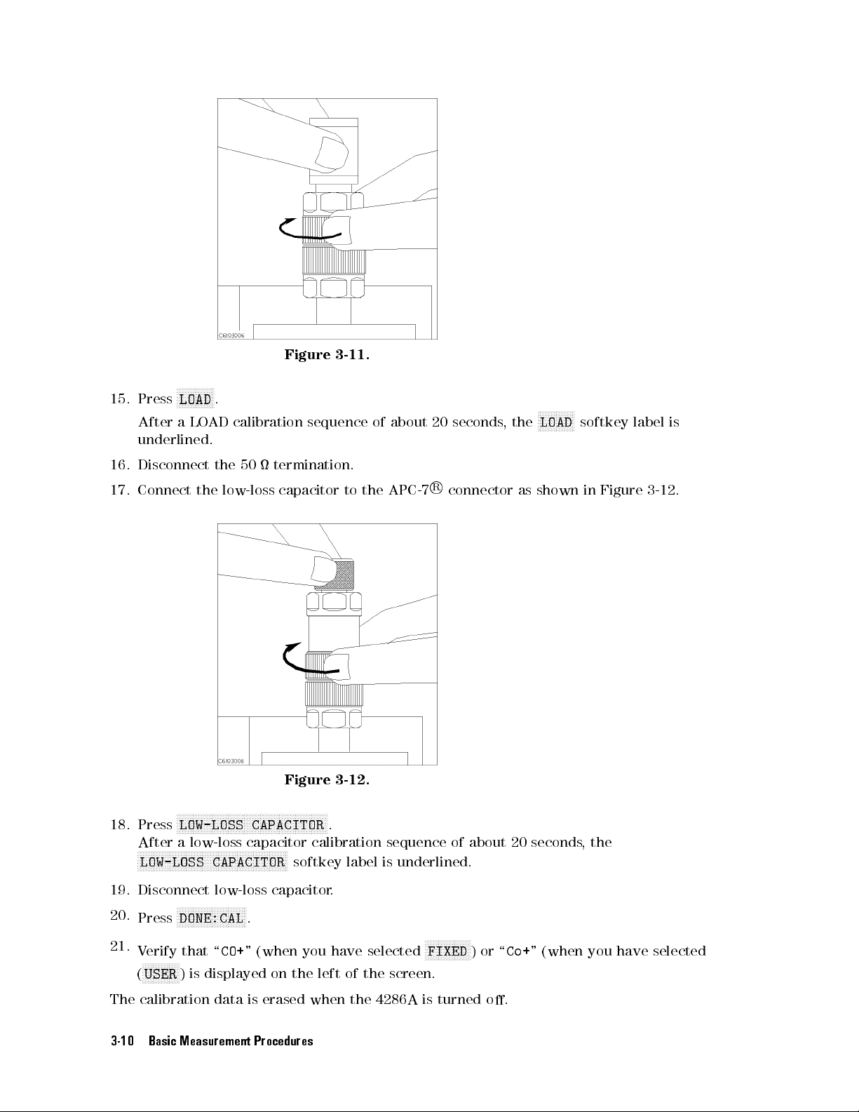
15.
Press
After
underlined.
16.
Disconnect
17.
Connect
N
N
N
N
N
N
N
N
LOAD
a
LO
the
N
N
N
N
N
N
.
AD
the
low-loss
Figure
calibration
50
termination.
capacitor
3-11.
sequence
to
the
of
APC-7
about
20
seconds
R
connector
N
N
N
N
N
N
N
N
N
N
N
N
N
N
LOAD
,
the
as
shown
softkey
in
Figure
label
3-12
is
.
Figure 3-12.
NNNNNNNNNNNNNNN
18. Press
LOW-LOSS CAPACITOR
After a low-loss capacitor calibration sequence of
NN
NNNNNNNNNNNNNNNNNNNNNNNNN
NNNNNNNNNNNNNNNNNNNNNNNNN
LOW-LOSS CAPACITOR
19. Disconnect low-loss capacitor
NNNNNNNNNNNNNNNNNNNNNNNNN
20.
21.
NNNNNNNNNNNNNNNNNNNNNNNNNN
Press
DONE:CAL
Verify that \
NNNNNNNNNNNNNN
(
USER
) is displayed on the left of the screen.
CO+
NNNNNNNNNNNNNNNN
.
NNNN
softkey label is underlined.
.
.
" (when you have selected
NNNNNNNNNNNNNNNNN
FIXED
about 20 seconds
)or\
The calibration data is erased when the 4286A is turned o.
3-10 Basic Measurement Procedures
,the
Co+
" (when you have selected
Page 37
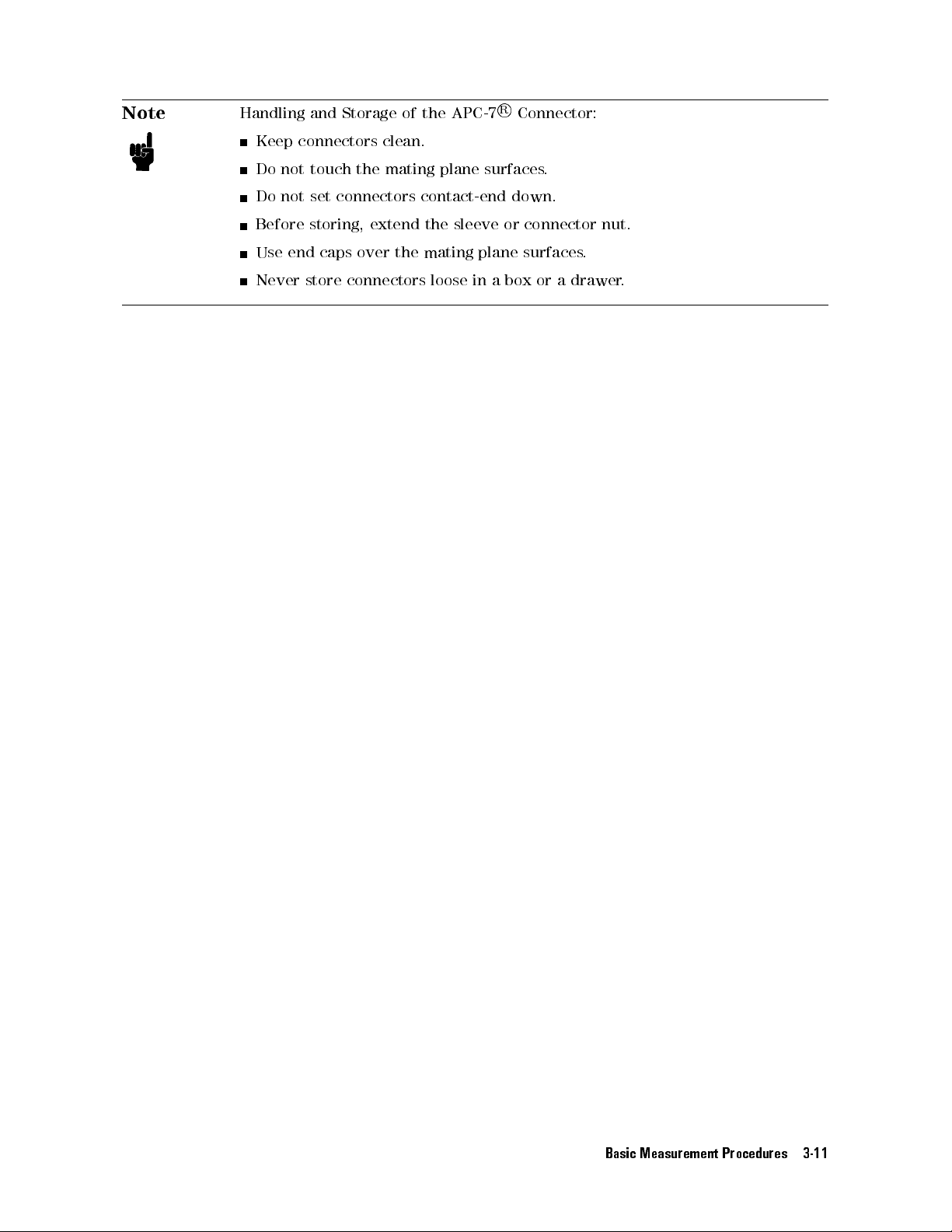
Note
Handling
Keep
Do
not
Do
not
and
Storage
connectors
touch
set
connectors contact-end
the
of
clean.
mating
the
APC-7
plane
R
Connector:
surfaces
down.
.
Before
Use
end
Never
storing,
caps
store
extend
over
the
connectors
the
sleeve
mating
loose in
or
plane
abox
connector
surfaces.
or a
drawer.
nut.
Basic Measurement Procedures 3-11
Page 38
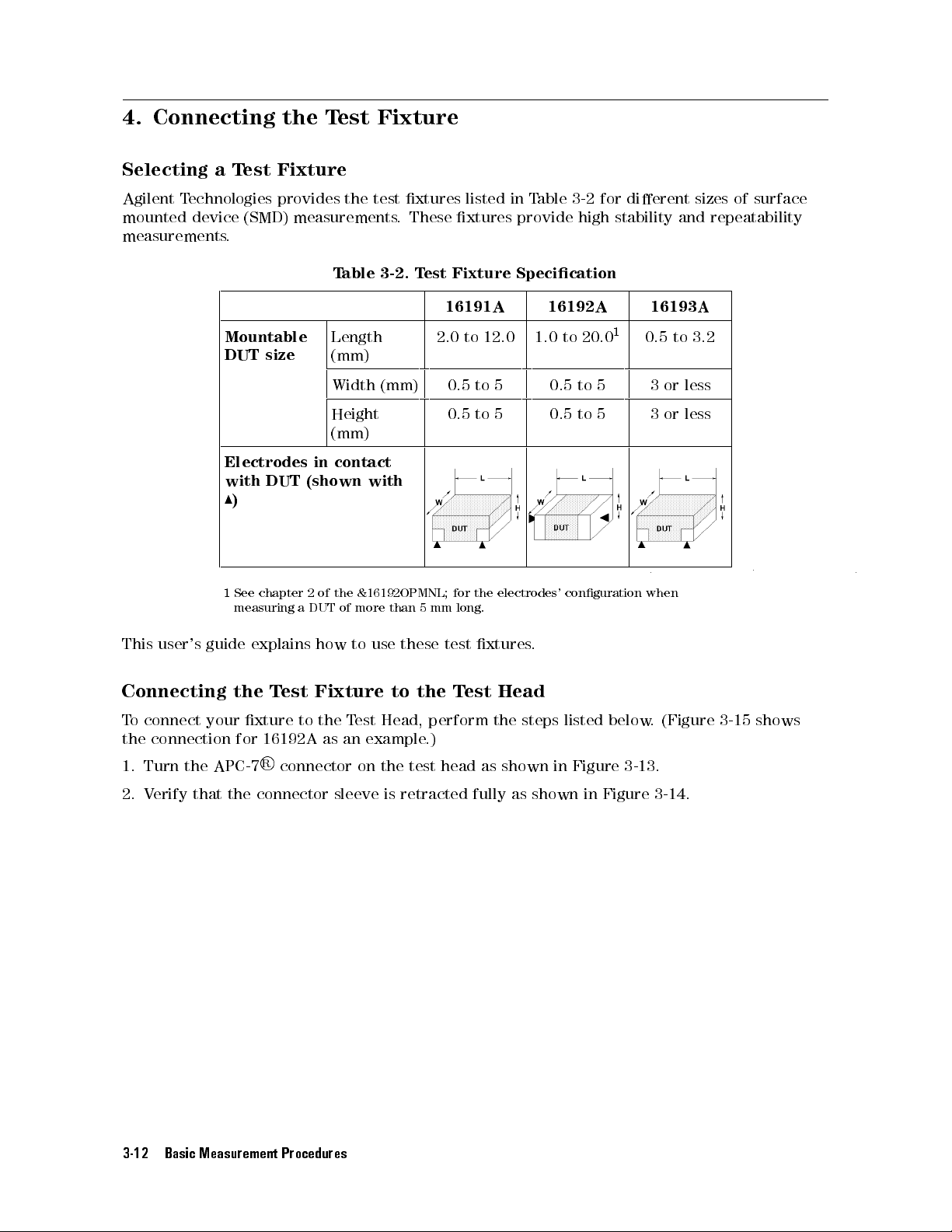
4. Connecting
the T
est Fixture
Selecting
Agilent
mounted
T
echnologies provides
device
measurements
a
Test
(SMD)
.
Mountable
DUT
size
Electrodes
with
DUT
8
)
1
See
chapter
measuring
Fixture
the test
measurements
T
able
Length
(mm)
Width
Height
(mm)
in
contact
(shown
2
of
the
a
DUT
of
xtures listed
.
These
3-2. T
est Fixture
(mm)
with
&16192OPMNL;
more
than
5
mm
in T
able 3-2
xtures provide
for dierent
high stability
and repeatability
Specication
16191A 16192A 16193A
1
2.0
0.5
0.5
for
to
to
to
the
12.0
5
5
electrodes'
1.0
to
0.5
0.5
conguration
20.0
to
to
5
5
0.5
3
or
3
or
when
to
long.
sizes of
3.2
less
less
surface
This
user's
guide
Connecting
T
o
connect
the
connection
1.
Turn
2.
V
erify
the
that
your
APC-7
explains
the
xture
for
the
connector
T
est
16192A
R
connector
how
Fixture
to
the
as
sleeve
to
T
est
an
example
on
use
these
to
the
Head,
perform
.)
the
test
is
retracted fully
test
T
est
head
xtures
Head
the
as
shown
as shown
.
steps
listed
in
Figure 3-13
in Figure
below.
(Figure
.
3-14.
3-15 shows
3-12 Basic Measurement Procedures
Page 39
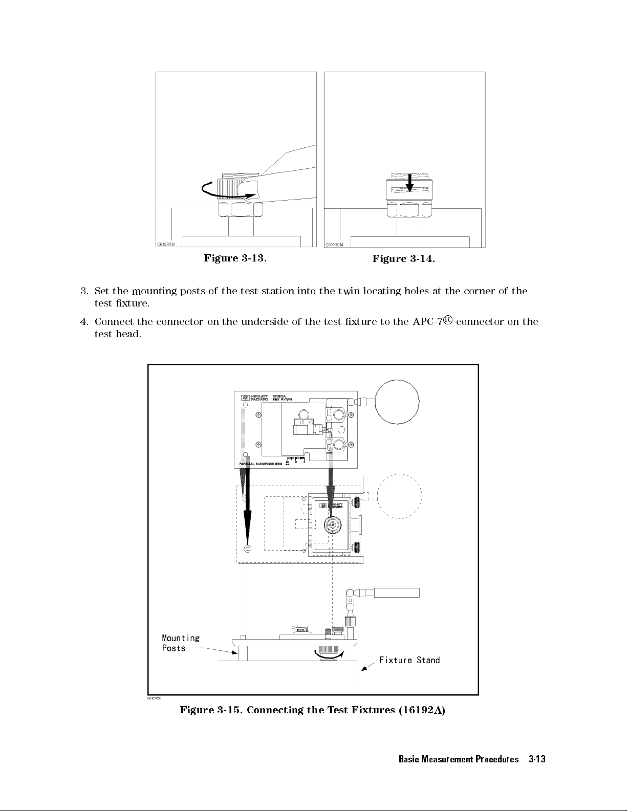
3.
Set
test
4.
Connect
test
the
mounting
xture
head.
.
the
connector
posts
Figure
of
the
on
the
3-13.
test
station
underside
into
of
the
the
test
twin
xture
Figure
locating
to
the
3-14.
holes
APC-7
at
the
R
corner
connector
of
on
the
the
Figure 3-15. Connecting the Test Fixtures (16192A)
Basic Measurement Procedures 3-13
Page 40
5. Setting
In
the
RF
region,
transmission
error
is
electrical
can
set
line
compensated
length
the
electrical
the Electrical
the wavelengths
length
values
of
the test
by
the electrical
for
the Agilent
length parameter
Length of
are short
xture.
and are
This causes
length parameter
Technologies
by selecting
the T
est Fixture
not negligible
a phase
for the
test xtures
the xture
compared to
shift error
test xture
.The
. Because
are stored
model number
the physical
phase shift
in the
.
the
4286A,
you
Setting
1.
Press
2.
Press
3.
Select
4.
Press
5.
V
erify
Procedure
5
.
4
Cal
NN
NN
NN
NN
N
N
N
N
N
N
N
N
N
N
N
N
N
N
N
N
N
FIXTURE[]
the
xture
N
N
N
N
N
N
N
N
N
N
N
N
N
N
N
N
N
N
N
\
N
.
Del
RETURN
that
NN
NN
and
model
"
appears
NN
NN
NN
NN
N
N
N
N
SELECT FIXTURE
then
number
on
the
N
N
N
N
N
N
N
N
N
N
that
left of
N
N
N
NN
NN
NN
NN
N
N
N
you
are
the display
N
N
N
N
N
N
N
N
.
using.
.
3-14 Basic Measurement Procedures
Page 41
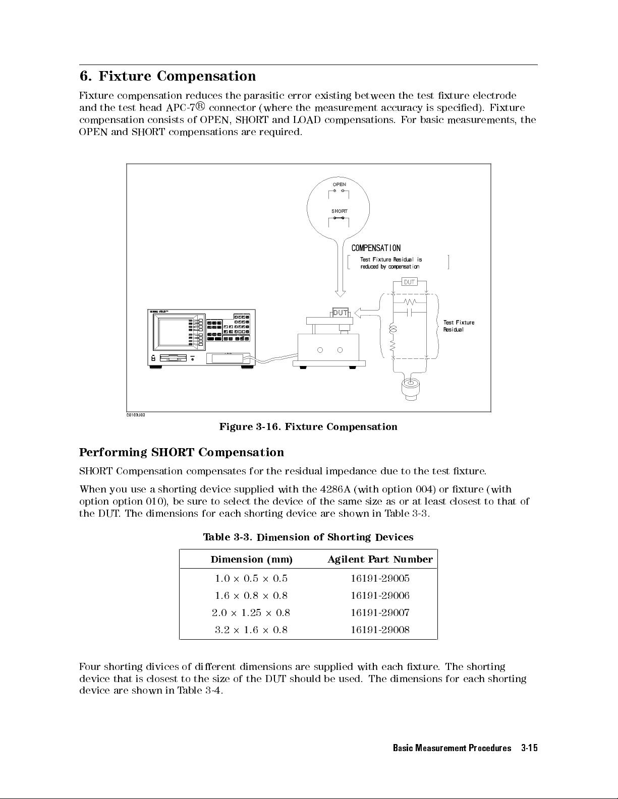
6. Fixture
Compensation
Fixture
and
compensation
the
test
compensation
OPEN
and
SHORT
head
APC-7
consists
compensations
reduces
R
connector
of
OPEN,
the
parasitic error
(where
SHORT and
are required.
existing between
the
measurement
LOAD
compensations.
the test
accuracy is
For
basic measurements
xture electrode
specied). Fixture
,the
P
erforming
SHORT Compensation
SHORT Compensation
When
you
use a
shorting device
option
the
DUT
option
.The
010), be
dimensions for
Figure
compensates for
sure to
select the
each shorting
T
able
Dimension (mm)
1.020.5
3-16.
Fixture
the residual
supplied with
device of
device are
3-3.
Dimension
2
0.5 16191-29005
Compensation
impedance due
the
4286A
the
same
shown
of Shorting
Agilent P
(with
option
size
in
Devices
art Number
as
T
able
or
to
the
004)
at
3-3
test
least
.
or
closest
xture
xture
.
(with
to
that
1.620.820.8 16191-29006
2.021.25
2
0.8 16191-29007
3.221.620.8 16191-29008
Four shorting divices of dierent dimensions are supplied with each xture. The shorting
device that is closest to the size of the DUT should be used. The dimensions for each shorting
device are shown in Table 3-4.
of
Basic Measurement Procedures 3-15
Page 42
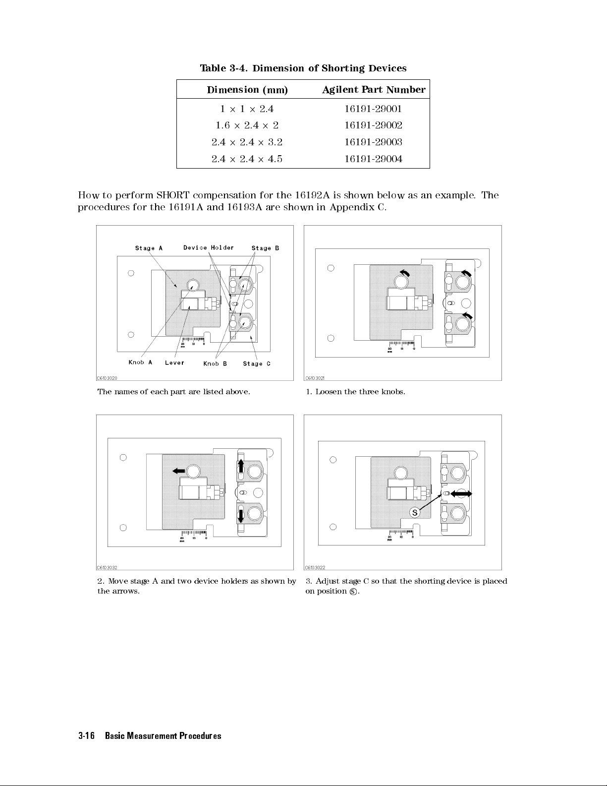
T
able 3-4.
Dimension of
Shorting
Devices
How
to
perform
procedures
for
SHORT
the
Dimension
1.6
2.4
2.4
compensation for
16191A
and 16193A
(mm)
1
2
1
2
2.4 16191-29001
2
2.4
2
2
2
2.4
2
3.2
2
2.4
2
4.5
the 16192A
are shown
Agilent
Part
16191-29002
16191-29003
16191-29004
is shown
in Appendix
Number
below as
C.
an
example
.
The
The
names
of
each
part
are
listed
above
.
2. Move stage A and two device holders as shown by
the arrows
.
1.
Loosen
the
three
knobs
.
3. A
djust stage C so that the shorting device is placed
on position
s.
3-16 Basic Measurement Procedures
Page 43
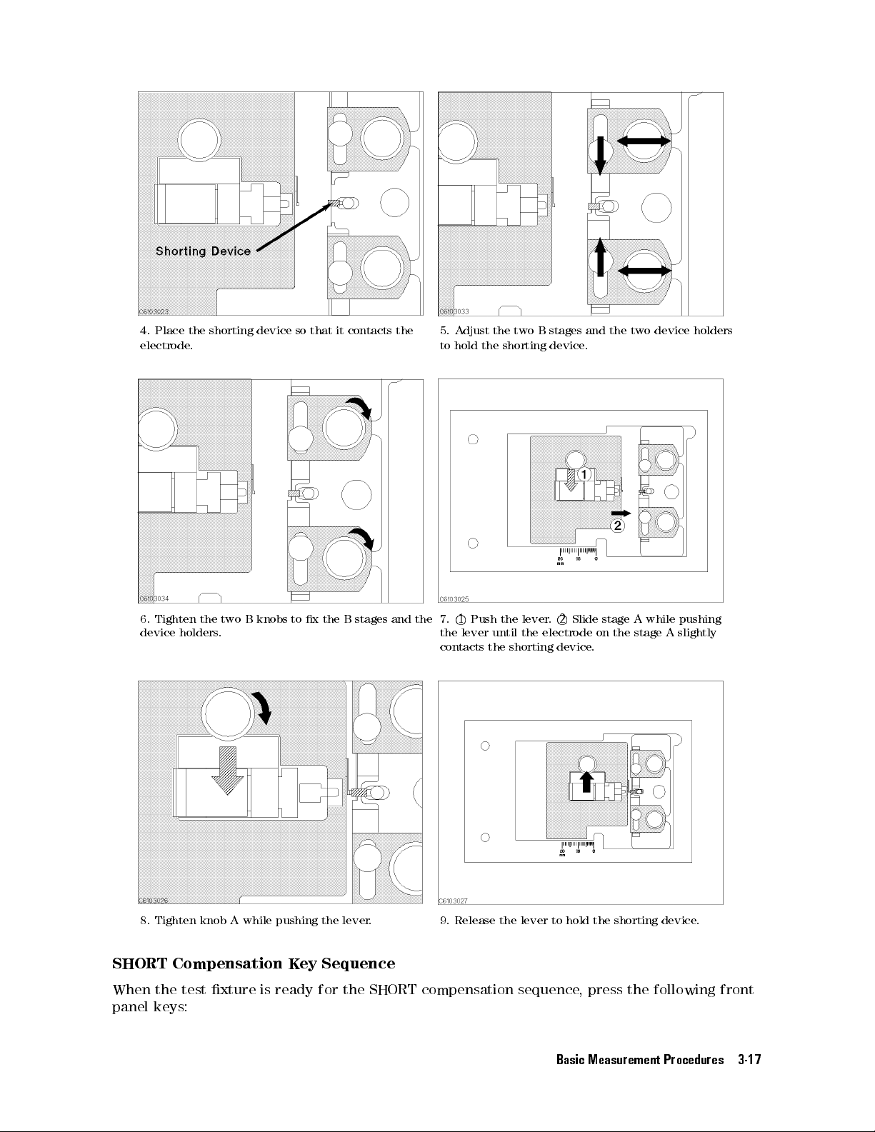
4.
Place
electrode.
6. Tighten
device
holders
the
shorting device
the two
.
B
knobs
so that
to
x
it contacts
the
B
stages
the
and
the
5.
A
djust
to hold
7.
1
Push
the
lever
contacts
the two
the
the
until
the
B stages
shorting
lever
the electrode
shorting
device
.
2
device
and the
.
Slide
stage
on the
.
two
A
stage
device
while
pushing
A
slightly
holders
8. Tighten knob A while pushing the lever. 9. Release the lever to hold the shorting device.
SHORT Compensation Key Sequence
When the test xture is ready for the SHORT compensation sequence, press the following front
panel keys:
Basic Measurement Procedures 3-17
Page 44
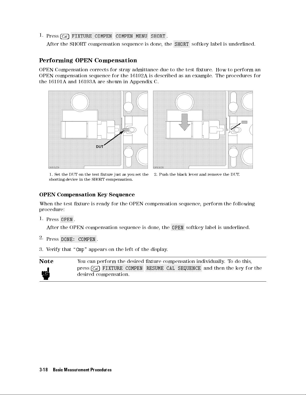
1.
Press
4
Cal
After the
P
erforming
N
N
NN
NN
NN
NN
NN
NN
N
N
N
N
N
N
N
N
N
N
N
N
N
NN
NN
FIXTURE
5
SHORT compensation
OPEN Compensation
NN
COMPEN
NN
NN
NN
NN
N
N
N
N
N
N
COMPEN
NN
NN
NN
NN
NN
N
N
N
N
N
N
N
N
N
N
MENU
sequence is
N
NN
NN
NN
NN
NN
NN
N
N
N
SHORT
done,
N
.
the
NN
NN
NN
NN
NN
NN
SHORT
N
N
N
N
N
softkey
label is
underlined.
N
N
N
NN
NN
NN
NN
N
OPEN
OPEN
the
OPEN
When the
procedure:
1.
2.
Compensation
compensation
16191A
1.
Set
shorting device
Compensation
N
Press
After
the
N
Press
and 16193A
the
DUT
test
xture
N
NN
NN
N
N
N
N
N
N
N
N
OPEN
.
OPEN
N
N
NN
NN
NN
NN
N
N
N
N
N
N
N
DONE:
N
corrects
sequence
are shown
on
the
test
in
the
SHORT
K
is
ready
compensation
N
N
N
N
N
N
N
N
N
NN
NN
NN
NN
N
COMPEN
N
.
for
for
xture
just
compensation.
ey
Sequence
for
stray
admittance
the
16192A
in Appendix
as
you
set
the
OPEN
sequence
due to
is described
C.
2.
the
is
Push
compensation
done
,
the
the
N
N
N
N
OPEN
N
N
the test
black
N
as an
example.
lever
sequence
N
N
N
N
N
N
N
softkey
xture.
and
remove
,
perform
label
How to
The procedures
is
perform
the
DUT
.
the
following
underlined.
an
for
3.
V
erify
that
\
Cmp
" appears
Y
ou
can
Note
press
desired
3-18 Basic Measurement Procedures
perform
N
NN
N
N
N
N
FIXTURE
5
4
Cal
compensation.
on the
the desired
N
N
N
N
N
N
N
NN
NN
NN
NN
left of
NN
NN
NN
N
N
N
N
N
N
COMPEN
the display
xture compensation
N
NN
N
N
N
N
N
N
NN
NN
N
RESUME
N
N
N
.
N
N
N
N
N
N
N
NN
NN
NN
NN
NN
CAL
NN
NN
N
N
N
N
N
N
N
SEQUENCE
N
NN
NN
NN
NN
NN
individually.
NN
NN
N
N
N
N
N
N
and
N
N
N
then
To
the
do this
key
for
,
the
Page 45
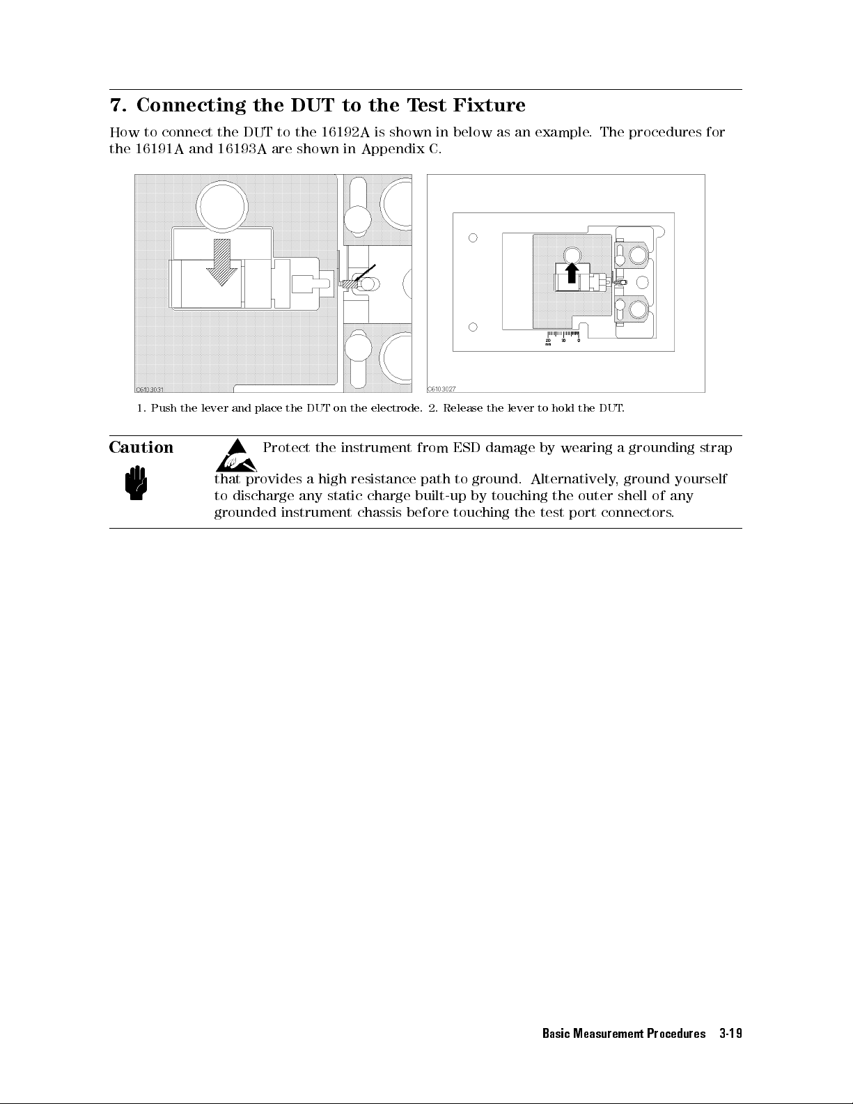
7. Connecting
How
to
the
connect
16191A
1.
Push
the
and
lever
the
16193A
and
the DUT
DUT to
the 16192A
are shown
place
the
DUT
on
to the
Test
is shown
in Appendix
the
electrode.
Fixture
in below
C.
2.
Release
as an
the
lever
example.
to
hold
the
The procedures
DUT
.
for
Caution
Protect
that
provides
to
discharge
grounded
the
instrument
a
high
any
static
instrument
resistance
charge
chassis
from
path
built-up
before
ESD
damage
to
ground.
by
touching
touching
by
wearing
Alternatively
the
the test
port
a
,
outer
shell
connectors
grounding
ground
of any
.
strap
yourself
Basic Measurement Procedures 3-19
Page 46
8. Measuring
After
you
place
the
the DUT
DUT on
the test
xture,
the measured
result is
displayed.
3-20 Basic Measurement Procedures
Page 47
4
4286A
This chapter
each of
with Chip
describes
those
Dierentiation of
GO/NO-GO T
Contact
Enabling
Display
Setup
Setting up
This
system
4286A
Electrical
P
erforming
Restoring
Check
Beeper
Updating
Linking
chapter
in
the
Measurement
Specication
Settings
Handler
also
the
functions
DUT
est
with
Limit
ON/OFF
4286A
Interface
includes
production
Time
Calibration
After
functions
when
s
through
and
the
line
of
with
P
ower
Handler
the
4286A
BIN
T
est
Function
Chip
Handler
Board
technical
.
Handler
W
orking
Interruption
available
is
used
Sorting
information
Interface
Standard
with
with
the
for
4286A
a
chip
using
and
handler
4286A
operation
.
with
automatic
procedures
selection
for
Note
When
you
interface
Handler
use
the
board
Interface
4286A
before
Board"
together
performing
for
details
with
limit
.
a
chip
test
handler
or
BIN
,
be
sorting.
sure
See
to
set
up
\Setting up
the
4286A with Chip Handler 4-1
Page 48
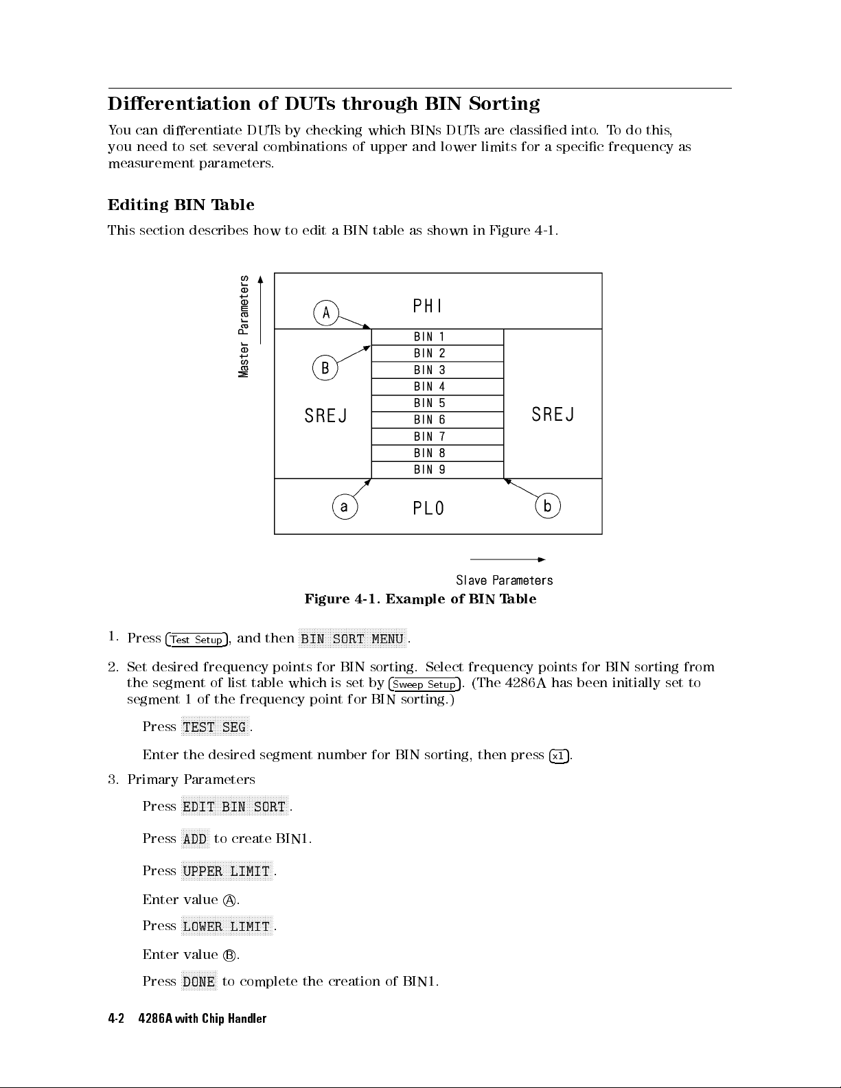
Dierentiation of
Y
ou
can
dierentiate
you
need
to
measurement
set
parameters
DUTs
several combinations
DUTs
by checking
.
through BIN
which BINs
of upper
DUTs
and lower
Sorting
are classied
limits for
into.
a specic
To
do
this
,
frequency as
Editing
This
BIN T
section describes
able
how
to
edit
a
Figure
BIN
4-1.
table
Example
as
shown
of BIN
in
Figure
Table
4-1
.
1.
Press
2.
Set
the
segment
4
T
desired
segment
Press
est
N
Setup
frequency
of
1
of
the
N
N
NN
NN
NN
NN
N
N
N
TEST
5
,
and
list
frequency
N
N
N
N
N
N
N
N
N
N
N
SEG
.
table
Enter the desired
3. Primary P
Press
arameters
NNNNNNNNNNNNNNNNNNNNNNNN
NNNNNNNNNNNNNNNNN
EDIT BIN SORT
NNNNNNNNNNN
Press
ADD
to create BIN1.
NNNNNNNNNNNNN
Press
Enter valueA
Press
Enter valueB
NNNNNNNNNNNNNNNNNNNNNN
UPPER LIMIT
.
NNNNNNNNNNNNNNNNNNNNNNNNNNNNNNNNNN
N
LOWER LIMIT
.
NNNNNNNNNNNNNN
Press
DONE
to complete the creation of BIN1.
4-2 4286A with Chip Handler
N
N
N
N
N
N
N
N
N
NN
NN
N
N
N
N
N
N
N
N
N
N
N
N
N
N
N
N
N
N
N
N
N
NN
NN
N
N
then
points
which
BIN
point
for
SORT
BIN
is
set
for
N
MENU
sorting.
by
4
Sw
BIN
sorting.)
.
eep
Select
Setup
frequency
5
.
(The
4286A
segment number for BIN sorting, then press
.
.
.
points
has
5
4
x1
been
.
for
BIN
sorting
initially
set
from
to
Page 49
Repeat
4.
Secondary P
Press
Press
Enter
Press
Enter
Press
Press
5.
Press
the steps
arameters
NN
NN
NN
NN
NN
NN
N
N
N
N
SEC REJECT
NN
NN
N
N
N
N
N
N
N
N
N
N
N
NN
UPPER LIMIT
value
N
N
N
N
N
N
N
N
N
N
N
N
NN
NN
LOWER
value
N
N
N
N
N
N
N
N
N
NN
NN
NN
NN
SEC
REJECT
N
N
N
NN
NN
NN
N
N
N
N
N
N
N
RETURN
N
N
N
N
N
N
N
N
N
N
N
N
N
N
DONE
to
above to
N
N
N
N
N
N
N
NN
NN
NN
NN
NN
NN
MENU
NN
NN
NN
NN
NN
NN
N
N
N
N
N
N
a
.
NN
NN
N
N
N
N
N
N
N
N
N
N
N
N
N
N
N
LIMIT
b
.
N
N
N
N
N
N
N
N
N
N
N
N
N
N
N
N
N
NN
on
N
N
N
N
to complete
complete
NN
N
N
N
N
N
N
N
N
.
.
NN
NN
NN
N
N
N
OFF
the
create BIN2
N
N
.
N
N
N
N
N
N
N
N
to
toggle
the secondary
creation
through BIN9.
N
N
N
N
N
N
N
N
N
NN
ON
off
it
parameter setting.
of
BIN
table
NN
NN
NN
N
N
N
.
.
Setting
1.
Set
abount
2. Press
3.
Select
The
Denitions
\Setting
4.
Press
BIN
1.
Press
2.
Press
When
follows:
On-screen
Beeper (ON/OFF selectable)
up
up
the
the
4
T
est
N
N
N
N
N
N
N
N
N
N
MODE
pattern
up
N
N
N
N
N
N
N
N
N
N
N
RETURN
Sorting
4
T
est Setup
N
N
N
N
NN
NN
NN
N
BIN SORT
the
BIN
Message Showing Corresponding BIN or BIN OUT (if outside preset limits)
Handler
handler
mode
.
5
,
N
N
N
N
N
N
N
N
N
N
1
or
of
output
in
output
Handler
N
N
NN
N
N
N
N
.
5
N
N
N
N
N
N
N
N
N
N
N
N
sort
and then
and
N
N
N
N
N
NN
on OFF
key
Setup
N
N
interface
N
N
N
N
N
N
N
MODE
Interface
then,
NN
NN
N
N
is
Interface
board. See
N
N
N
N
NN
NN
N
HANDLER IF
N
N
N
N
N
N
N
N
N
N
N
N
N
2
.
signals
signals
N
N
N
N
N
N
ON,
N
N
N
N
N
BIN
N
N
N
N
to toggle
measured
for
N
N
N
for
N
N
N
N
N
N
N
N
N
N
N
N
N
N
BIN
handler
Board"
N
N
N
N
N
N
N
N
N
NN
NN
SORT
it
N
N
N
N
N
N
N
N
NN
sorting
for
NN
NN
N
N
N
N
N
MENU
N
N
N
N
NN
ON off
data
.
N
N
NN
\Setting up
can
interface
details
N
N
N
N
N
N
N
N
.
NN
N
N
N
N
N
N
N
N
N
N
.
outside
Handler Interface
be
selected from
vary
depending
about
the
mode
the
limits
are
either
on
.
output
Board"
Mode
the
mode used.
and
for
details
1
or
displayed
Mode
See
as
2.
GPIB Command
Handler Interface Output
:DATA? BIN
4286A with Chip Handler 4-3
Page 50
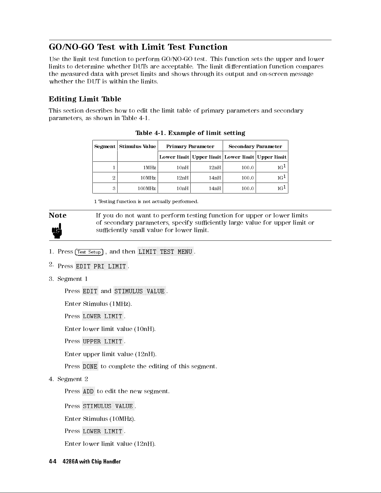
GO/NO-GO T
Use
the
limit
test
limits
to
determine
the
measured
whether
the
data
DUT
est with
function to
whether
with
preset limits
is
within the
Limit T
perform GO/NO-GO
DUTs
are acceptable
limits.
est Function
and shows
test. This
. The
limit dierentiation
through its
function sets
output and
the upper
function compares
on-screen message
and lower
Editing
This
section
parameters
Note
1.
Press
4
N
2.
Press
3.
Segment
N
EDIT
Press
Limit
describes
,
as
shown
Segment Stimulus
1
T
esting function
If
of
suciently
Setup
N
N
N
N
N
N
N
N
1
N
N
NN
NN
NN
EDIT
N
N
N
N
PRI
NN
N
N
NN
N
N
and
5
T
est
N
N
N
N
N
N
T
able
how
to
edit
the
limit
table
of
primary
in
T
able
4-1
.
T
able
4-1.
Example
actually
to
NN
N
N
N
N
N
N
N
NN
NN
NN
N
N
Primary
Lower
performed.
perform
,
specify
for
N
N
N
N
N
N
N
N
N
N
N
N
N
N
TEST
N
N
N
N
N
N
.
limit
lower
N
N
NN
MENU
V
alue
1 1MHz 10nH 12nH 100.0 1G
2 10MHz 12nH 14nH 100.0 1G
3 100MHz 10nH 14nH 100.0 1G
is
not
you
do
not
want
secondary
,
and
N
N
N
N
N
N
N
N
N
N
N
N
N
N
LIMIT
N
N
N
NN
STIMULUS
then
N
N
N
N
NN
NN
N
N
N
N
.
NN
N
N
parameters
small
value
N
N
N
N
N
N
N
N
N
LIMIT
N
N
N
N
N
N
N
N
N
N
N
N
N
N
N
NN
VALUE
P
testing
N
N
N
N
N
N
N
arameter
Upper
N
N
N
N
of
limit
suciently
limit.
.
parameters
setting
Lower
limit
function
Secondary
limit
for
upper
large
value
and
P
arameter
Upper
or
for upper
secondary
limit
1
1
1
lower
limits
limit or
Enter
Press
Enter lower
Press
Enter upper limit value (12nH).
Press
4. Segment 2
Press
Press
Enter Stimulus (10MHz).
Press
Enter lower limit value (12nH).
4-4 4286A with Chip Handler
Stimulus
N
NN
NN
NN
N
LOWER
N
N
N
NN
N
N
N
UPPER LIMIT
NNNNNNNNNNNNNN
DONE
NNNNNNNNNNN
ADD
NNNNNNNNNNNNNNNNNNNNNNNNNNNNNNNNNNNNNNNNNNNN
STIMULUS VALUE
NNNNNNNNNNNNNNNNNNNNNNNNNNNNNNNNNNN
LOWER LIMIT
(1MHz).
N
N
N
N
N
N
N
N
N
N
N
N
N
N
N
N
NN
NN
NN
NN
N
LIMIT
limit value
N
N
N
N
N
N
N
N
NN
N
N
N
N
N
N
N
N
N
N
NN
N
N
N
to complete the editing of this segment.
to edit the new segment.
N
N
.
N
N
.
.
(10nH).
.
Page 51

5.
Segment
6.
Press
Then,
Press
Enter
Press
Press
Enter
Press
N
DONE
press
N
NN
NN
NN
NN
NN
NN
N
UPPER
upper limit
NN
NN
NN
NN
NN
NN
N
N
DONE
3
N
NN
N
N
N
N
N
N
N
N
ADD
to
stimulus
N
N
N
N
N
N
N
N
N
N
N
N
N
N
DONE
N
N
N
N
N
N
N
N
NN
NN
N
to
N
N
N
N
N
N
N
N
NN
NN
EDIT
N
N
N
N
N
N
N
N
N
N
N
N
NN
NN
NN
NN
LIMIT
value
to
complete the
edit
the
,
lower
to
complete
complete
NN
N
N
N
N
N
N
N
N
N
N
N
N
N
N
N
N
N
SEC
LIMIT
N
.
N
N
NN
new
limit,
the
NN
NN
N
N
N
(14nH).
editing of
segment.
and
the
editing
editing
N
N
to
edit
this segment.
upper
limit
values in
of
this
segment.
of
the
primary
the
secondary parameter
the same
parameter
manner above
limit table
limit table
.
.
.
1. Segment
Press
Enter lower
Press
Enter
Press
2.
Segment
Enter
segment
Setting
1.
Set up
procedure
2.
Press
3.
Press
When
output
NNNN
NNNNNNNNNNNNNNNN
MODE 1
NNNN
NNNNNNNNNNNNNNNN
MODE 2
See \Setting up Handler Interface Board" for details abount the mode
4.
Press
1
N
N
N
NN
NN
N
N
N
N
N
N
N
N
N
LOWER
N
N
N
N
N
N
N
N
N
N
N
N
N
N
NN
UPPER
upper
N
N
N
N
N
N
N
N
N
N
NN
NN
DONE
2,3
lower
in
the
up
Handler
the handler
.
4
T
est
Setup
N
NN
N
N
N
N
N
N
N
N
N
N
N
N
N
N
N
N
MODE
you
for
NNNNNN
RETURN
N
1
perform
the
NNNNNNNNNNNNNN
.
N
N
N
N
N
N
N
N
N
N
N
N
NN
NN
N
N
N
LIMIT
limit
NN
NN
LIMIT
limit
to
and
5
,
or
interface
.
value
(100.0).
N
N
N
N
N
N
N
N
N
N
N
N
N
N
N
.
value
(1G).
complete
upper limit
same
interface board.
and
N
NN
N
N
N
N
N
N
MODE
limit
Outputs overall results of comparison for limit test.
Outputs results for each segment.
the
manner
Interface
N
N
N
N
N
N
N
N
N
HANDLER
then
N
N
N
N
N
N
N
N
N
N
N
2
.
test,
select the
varies
editing
values
as
N
N
NN
NN
depending the
segment
See
NN
N
N
N
N
N
N
N
N
N
N
IF
of
this segment.
and
\Setting
N
N
N
N
N
.
signal pattern
press
1.
N
N
N
N
DONE
up
mode
N
N
N
NN
N
N
N
N
N
to
Handler
from either
used
complete
Interface
as
follows
the editing
Board"
Mode 1
.
or Mode
.
of
for
this
the
2. The
set
up
4286A with Chip Handler 4-5
Page 52

Limit
Y
ou
can
1.
Press
2.
Press
parameters)
When
either
displayed
T
est
perform
4
Test
Setup
N
N
N
NN
NN
NN
NN
NN
PRI
of
as
follows:
limit
5
,
and
NN
NN
N
N
N
N
N
N
N
N
N
N
N
NN
NN
NN
LIMIT on
to
toggle it
the
limit
test
NN
NN
for
then
NN
NN
N
N
N
OFF
N
test
only
N
N
N
N
N
N
N
LIMIT
N
N
N
N
N
(primary
N
N
N
NN
NN
NN
NN
N
ON
off
keys
primary
N
N
N
N
NN
NN
NN
NN
NN
NN
TEST
parameters) or
N
N
N
N
N
N
N
.
is
ON,
or
NN
N
N
N
N
N
N
N
N
N
N
N
NN
MENU
measured
secondary parameters
NN
NN
NN
NN
N
.
N
N
N
NN
NN
NN
NN
NN
NN
NN
N
N
N
N
N
SEC
N
LIMIT on
data outside
.
N
N
N
N
N
NN
NN
NN
NN
NN
NN
the limits
NN
N
N
N
N
N
N
N
N
OFF
(secondary
are output
and
On-screen
Beeper
GPIB
Note
F
AIL
(ON/OFF
Command
The frequency
independently
If
frequency
interpolation
F
with
Message
selectable)
:DATA?
the
frequency
or
example
the
LFA
,
:DATA?
(stimulus value)
of
of the
of
list
of
the
,
if
only
constant
LLIS
,
:DATA? LMAR
the frequency
limit
table
table
,limit
limit
one
upper
tests
values
point
limit
of limit
set in
for
.
is
dened
and
table
the
does
not
all
measurements
lower
limit
for
list
table
equal
in limit
for
setting
limits
.
to
the
measurement
can
table,
limit test
all
measurements
can
be
performed
is performed
be
.
set
using
4-6 4286A with Chip Handler
Page 53
Contact Check
Contact
check
resistance
F
ollow
1.
2.
3.
4.
Contact check
check
consists
the
Press
4
Contact
Set
the
Press
Press
N
N
N
N
RDC
Press
Then,
Press
Whether
On-screen
Handler
GPIB
the measured
N
N
N
N
RDC
Command
is
procedure
upper
N
N
N
N
RDC
N
NN
NN
RDC
N
N
N
N
N
N
N
N
N
N
N
N
the
Interface
is
used
of
measuring
within
N
N
NN
N
N
NN
F
the
5
Check
and lower
N
N
N
NN
NN
NN
NN
N
N
N
N
N
N
N
UPPER
NN
N
N
N
N
N
N
N
N
N
N
N
N
N
N
N
LOWER LIMIT
N
N
N
N
N
N
N
N
NN
NN
NN
N
N
N
MEAS
on
NN
NN
NN
N
N
N
N
N
N
N
N
N
N
N
LIMIT
measured
results will
AIL
Message
to check
dc resistance
preset limits
below
.
.
limits for
N
N
N
N
N
N
N
N
N
N
NN
NN
NN
NN
N
N
N
LIMIT
N
N
NN
NN
NN
NN
N
N
N
N
N
N
N
N
N
N
N
N
N
N
N
N
N
N
N
N
N
N
N
N
N
N
N
NN
OFF
to
dc resistance
N
N
N
N
N
N
NN
NN
NN
NN
N
N
N
N
N
N
on
N
OFF
resistance
be output
the electrical
.
dc resistance
N
N
and
enter
N
N
and enter
toggle
to
it
will be
toggle
is
and
contact between
between the
the
upper
the lower
N
N
N
N
N
N
N
N
N
N
N
N
N
N
N
N
N
N
N
MEAS
displayed
N
N
N
N
N
N
N
N
N
NN
NN
RDC
LIMIT
the
N
NN
NN
RDC
N
it
within
displayed
two and
between the
limit.
limit.
NN
NN
NN
N
N
N
N
N
N
N
N
N
N
N
N
N
N
ON
off
on
N
N
N
N
N
N
N
N
N
N
N
N
N
N
N
N
N
NN
ON
limits
will
as
follows:
N
N
N
NN
NN
N
N
NN
.
the
NN
N
N
off
the test
determining whether
test
screen.
N
N
N
N
N
.
be
displayed
head and
head
on
and
the
DUT.
DUT
screen.
This
the
.
4286A with Chip Handler 4-7
Page 54
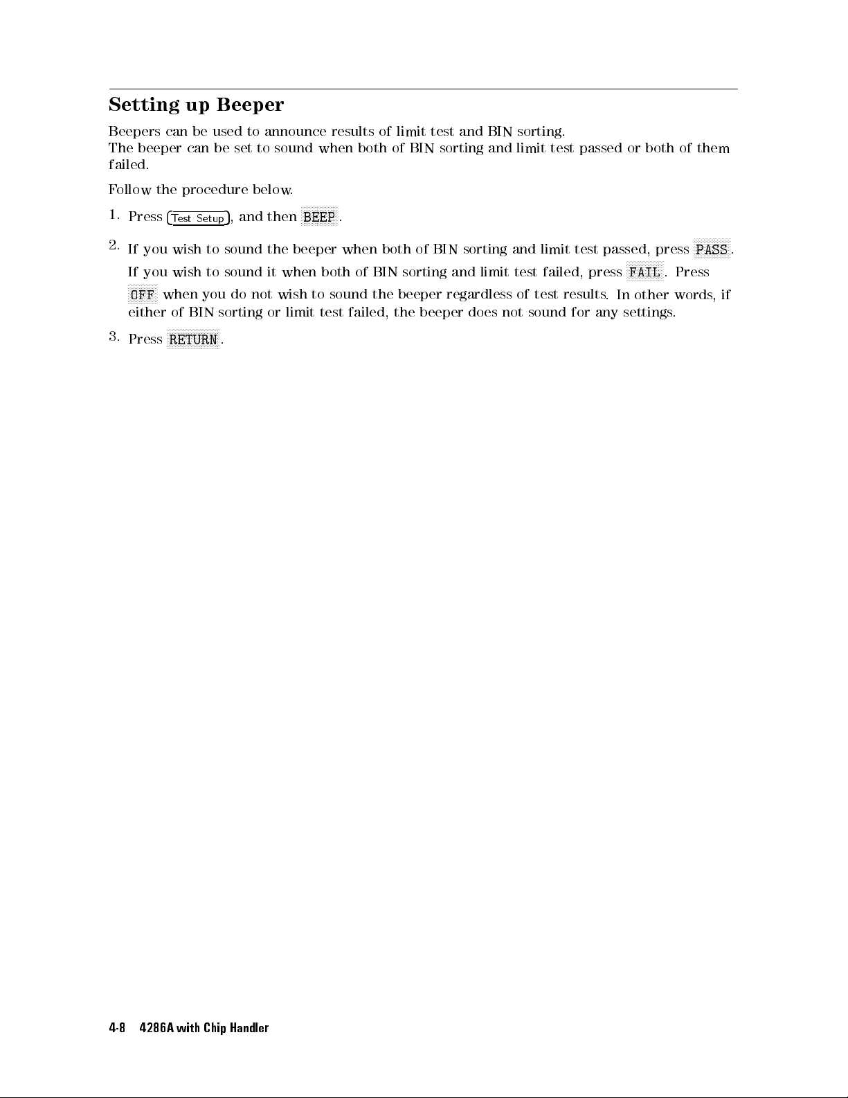
Setting up
Beeper
Beepers
The
beeper
failed.
F
ollow
1.
Press
2.
If
you wish
If you
N
NN
N
N
N
N
N
N
OFF
either
3.
Press
can
the
4
N
N
when
N
N
RETURN
T
wish to
of
N
N
be
used
can
be
procedure
Setup
5
est
to sound
sound
you
BIN
sorting
N
N
N
N
N
N
N
N
NN
NN
NN
N
N
.
to announce
set to
sound when
below
,
and
then
the beeper
it
when
do
not
wish
or
.
N
BEEP
limit
N
N
N
N
to
N
N
test
N
N
NN
both
results of
both of
NN
N
.
when
of
BIN
sound
the
failed, the
limit test
BIN sorting
both
of
sorting
beeper
and BIN
BIN
sorting
and
limit
regardless
beeper does
sorting.
and limit
and
test
of
test
not sound
test passed
limit
test
failed,
press
results
for
passed,
.
In
any
settings
or both
press
NN
NN
NN
N
N
N
N
N
N
N
N
FAIL
other
of
.
Press
words
.
them
N
NN
NN
NN
NN
PASS
,if
N
N
N
N
N
.
4-8 4286A with Chip Handler
Page 55
Display Updating
Y
ou
can
select
whether to
display
whether
Switching
This
F
ollow
updating
the
display
updating
the
procedure
function
DUT
is
updating
function
acceptable or
can
below.
ON/OFF
display new
ON
and OFF
not.
OFF
gains 3ms
be switched
measurement results
. Switch
this function
+ 6ms/point.
ON and
OFF at
any time
on the
OFF to
.
screen by
switching the
more quickly
determine
1.
2.
Press
Press
5
Displa
NN
NN
NN
N
N
.
y
N
N
N
N
N
N
N
N
N
N
N
N
4
NN
MEAS DISP
N
N
N
NN
NN
NN
NN
N
N
N
N
N
N
N
N
N
ON off
N
N
N
N
N
N
N
N
to switch
the
updating
function
ON
and
OFF
.
4286A with Chip Handler 4-9
Page 56
Setup Linking
The
4286A
allows
from
F
ollow
1.
Set
2.
Insert
the
the
the
up
can
be
4286A
moment
procedure
the
4286A for
a
3.5-inch
set up
to
of
4286A and
to read
run exclusively
startup.
below
.
use with
LIF or
DOS-formatted disk
Chip Handler
initial settings
for your
the handler
particular purpuse
.
from exible
into the
built-in disk
disk during
,the
chip handler
drive
startup.
.
This setup
for instance
,
3.
Press
4.
Press
destination.
5.
Press
6.
Enter
Before
drive
.
Each
handler
4
Save/Recall
NN
NN
N
N
N
N
N
N
N
STOR DEV
N
N
N
N
N
N
N
N
N
N
NN
STATE
AUTOREC
turning
time
from
N
N
N
NN
the
N
N
NN
5
N
N
N
N
N
N
NN
NN
N
.
as the
on
the
you
moment
.
to
switch
lename and
4286A
turn
,
on
of
startup
it
to
insert
4286A
NN
NN
N
N
N
N
N
N
N
N
N
[DISK]
press
the
,
it
recalls
.
N
N
N
N
N
N
disk
N
.
This
species
N
N
NN
NN
NN
N
N
N
N
N
N
DONE
.
containing
settings
in
the
the
the
built-in
\
AUTOREC
le
disk
drive
"
le
into the
to
operate exclusively
as
the
storage
built-in
for
disk
the
4-10 4286A with Chip Handler
Page 57
Setting up
This
section
There
are
describes
3
major
Handler Interface
the
steps necessary
steps as
follows:
Board
to use
the handler
interface board.
Mounting
Mount
resistor
Note
Setting
Set
the
The
Pull-up
a
pull-up
needs
up
up
the
4286A
.
following
resistor
to
have
A
pull-up
Handler
handler
step
Resistor
depends on
Interface
interface
is
required
modied.
Changing
Change
This
from
Checking
The
handler
Signal
the
is
necessary
the
default
Default
interface
I/O
switch
F
ormat
setting
when
settings
Settings
board
Signals
Comparator
Control Output
DC isolated
Signal
Signal This
Input
Signal
Internal power source (5V)
to
the
resistor
on
you
need
handler
must
signal
when
the
.
the signal
be
pattern
the
handler
the
I/O
Where to
I/O format.
mounted
that
power
supplies
interface
format
mount a
to
the
handler
suits
the
4286A
for
board
to change
that requires
resistor and
for
comparator
operation
I/O
or
COMMON
its signal
the switch
what
resistance
mode.
setting
I/O format.
settings dierent
.
has
been
set
as
follows
before
shipment.
Settings
This
signal
is
opto-isolated
COM1
ground.
voltage is
the handler
COM2 is
is
signal
used
as
Pull-up
supplied
.
is
opto-isolated
used as
ground. Pull-up
voltage is
the handler
This
supplied from
.
signal
is
opto-isolated
COMMON
resistors
from
COMMON
resistors are
and is
that
are
an
and
that
output
is isolated
mounted
external
is
output
is
isolated
mounted to
an external
from
the
through
to
the handler
power
through
the
power
internal
open-collector
from 4286A
source
open-collector
from
4286A
handler
source
circuits
Driving voltage is supplied from an external power source (5 to
7V) through EXT
is
connected to the COMMON of the external power source
.DCV2. This signal turns \TRUE" if input signal
Not used.
signals
Set it
should be
's
. Output
(5
to
24V)
's
.
Output
(5
to
15V)
of 4286A
the
.
up on
.
chassis
on
.
chassis
on
.
.
See \Handler Interface Board Switches" for default switch settings
Warning
Be sure to check the procedures in \Removing the T
removing the 4286A top cover
.
.
op Cover" before
4286A with Chip Handler 4-11
Page 58
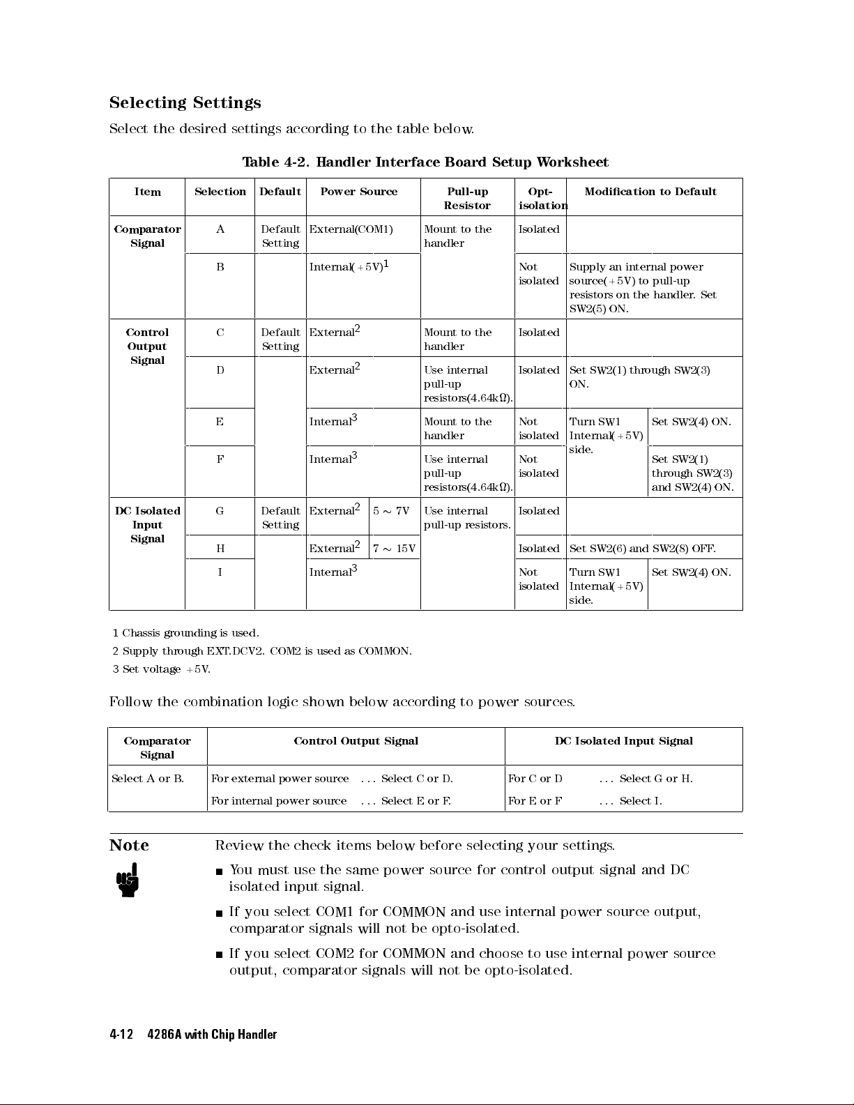
Selecting
Settings
Select
the
desired
settings
T
able
Item Selection Default P
Comparator
Signal
A Default
Setting
B Internal(+5V)
Control
Output
Signal
C Default
Setting
D External
E Internal
F Internal
DC
Isolated
Input
Signal
G Default
Setting
H External27
I Internal
according
4-2.
to
Handler
ower
the
Interface
Source
External(COM1) Mount
1
External
2
2
3
3
External25
3
table
below
Board
Resistor
handler
Mount
handler
Use
pull-up
resistors(4.64k).
Mount
handler
Use
pull-up
resistors(4.64k).
Use
7V
pull-up
15V
.
Pull-up
to
the
to
the
internal
to
the
internal
internal
resistors
Setup W
Opt-
isolation
Isolated
Not
isolated
Isolated
Isolated Set
Not
isolated
Not
isolated
Isolated
.
Isolated Set
Not
isolated
orksheet
Modication
Supply
source(+5V)
resistors
SW2(5)
SW2(1)
ON.
Turn
SW1
Internal(+5V)
side.
SW2(6)
Turn
SW1
Internal(+5V)
side
.
an
on
ON.
internal
to pull-up
the
handler
through
Set
Set
through
and
and
SW2(8)
Set
to
power
SW2(4)
SW2(1)
SW2(4)
Default
.
Set
SW2(3)
SW2(3)
SW2(4)
OFF
ON.
ON.
.
ON.
1
Chassis
2
Supply
3
Set
F
ollow
grounding
through
voltage +5V
the combination
EXT
.
is
used.
.DCV2.
Comparator
Signal
Select A or B
For external power source
.
For internal power source
Note
Review the check items below before selecting your settings
Y
ou must use the same power source for control output signal and DC
isolated input
If you select COM1 for COMMON and use internal power source output,
comparator signals will not be opto-isolated.
If you select COM2 for COMMON and choose to use internal power source
output, comparator signals will not be opto-isolated.
4-12 4286A with Chip Handler
COM2
is
used
logic shown
Control
signal.
as
COMMON.
below according
Output
Signal
. . . Select C or D
. . . Select E or F
to power
.
.
sources
For C or D
For E or F
DC
.
Isolated
Input
. . . Select G or H.
. . . Select I.
.
Signal
Page 59
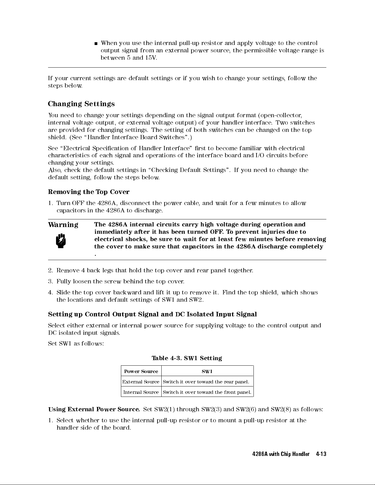
When you
use the
output signal
between 5
and 15V
internal pull-up
from an
external power
.
resistor
source
and
,
apply
the
permissible
voltage
to
the
voltage
control
range
is
If your
steps
Changing
Y
ou
internal
are
shield.
See
current settings
below
.
Settings
need
to
change
voltage
provided
(See
\Handler
\Electrical
characteristics
changing
Also
default
Removing
1.
Turn
,
check
your
the
setting,
the T
OFF
capacitors
W
arning
your
output,
for
changing
Interface
Specication
of
each
settings
default
follow
op Cover
the 4286A
in
the
4286A to
The
4286A
immediately
electrical
the cover
.
are default
settings
or
external
settings
of
Handler
signal
and
.
settings
the
steps
, disconnect
discharge.
internal
after
shocks
to
make
settings or
depending
voltage
.
The
Board
Switches".)
operations
in
\Checking
below
.
the
circuits
it
has
,
be
sure
sure
if you
on
output)
setting
Interface
of
Default
power
cable
carry
been
to
wait
that
capacitors
wish to
the
signal output
of
your
of
both
switches can
"
rst
to
the
interface board
Settings".
,
and
high
turned
for
OFF
at
change
handler
become
wait
for
voltage
.
T
o
least
in
the
your
settings
,
follow
format (open-collector
interface.
be changed
familiar
and I/O
If
you
a
few
during
prevent
few
minutes
4286A
need
Two switches
on the
with
electrical
circuits before
to
change
minutes
to
operation
injuries
before
discharge
allow
due
completely
the
,
top
the
and
to
removing
2.
Remove
3.
Fully
4.
Slide
the
Setting
Select
DC isolated
4
back
loosen
the
top
locations
up
Control
either
external or
input signals
the
cover
and
legs
that
screw
backward
default
Output
internal power
.
hold
behind
settings of
Signal and
the
the
and
top
cover
top
cover
lift
it
SW1 and
source for
and
rear
.
up
to
remove
SW2.
DC Isolated
supplying voltage
panel together
it. Find
the top
Input Signal
.
shield, which
to the
control output
shows
Set SW1 as follows:
Table 4-3. SW1 Setting
Power Source SW1
External Source Switch it over toward the rear panel.
Internal Source Switch it over toward the front panel.
Using External Power Source.
Set SW2(1) through SW2(3) and SW2(6) and SW2(8) as follows:
1. Select whether to use the internal pull-up resistor or to mount a pull-up resistor at the
handler side of the board.
and
4286A with Chip Handler 4-13
Page 60
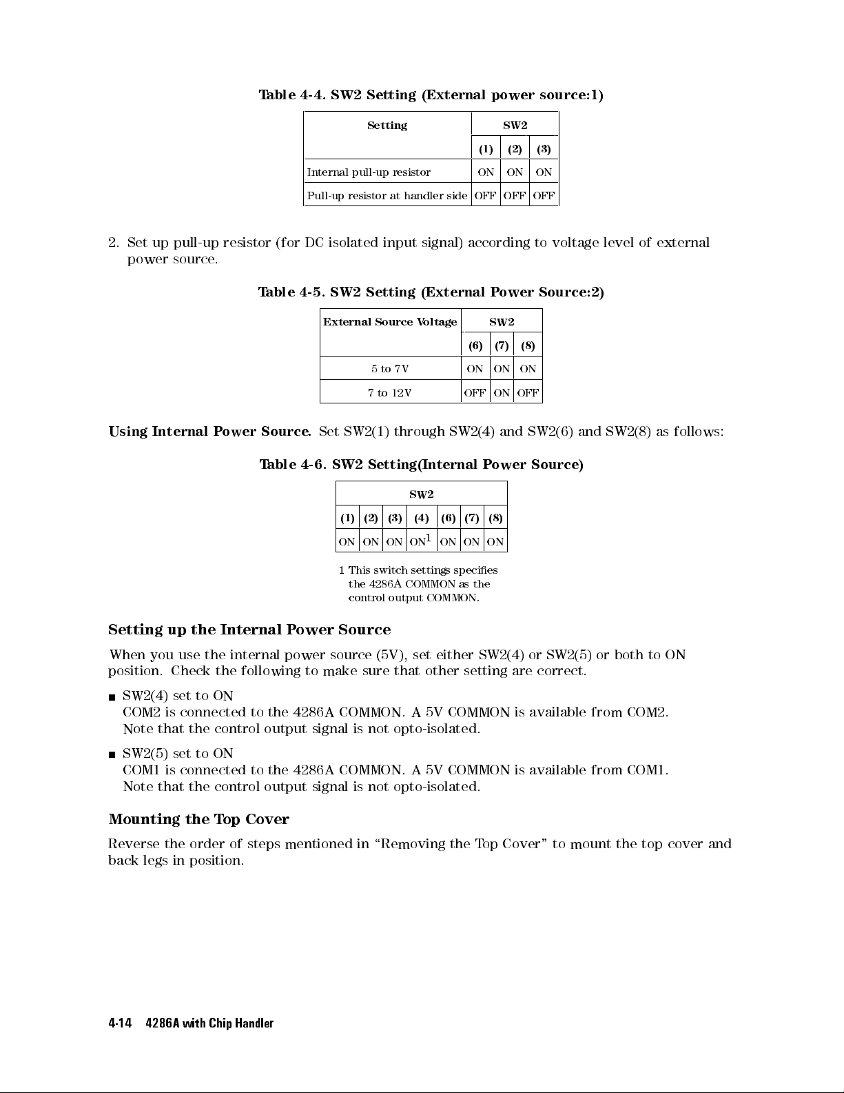
T
able 4-4.
SW2 Setting
(External
Setting SW2
power
source:1)
(1) (2) (3)
2.
Set
up
pull-up
power
source
Using Internal
resistor
.
P
ower
(for
T
able
Source
T
able
Internal pull-up
Pull-up
resistor
DC isolated
4-5. SW2
External
.
Set
SW2(1)
4-6.
SW2
resistor
at
handler
input signal)
Setting (External
Source
5
to
7V
7
to
12V
through
Setting(Internal
SW2
(1) (2) (3) (4) (6) (7) (8)
ON ON ON ON1ON ON ON
1
This
switch
settings
the
4286A
COMMON
control output
side
V
oltage
COMMON.
ON ON ON
OFF OFF OFF
according to
Power
SW2
(6) (7) (8)
ON ON ON
OFF ON OFF
SW2(4)
P
ower
species
as
the
and
voltage level
Source:2)
SW2(6)
Source)
and
of
SW2(8)
external
as
follows:
Setting up
When you
position.
SW2(4)
COM2
Note that
the Internal
use the
Check
set
is
the
to
ON
connected
the control
Power
internal power
following
to
output
the
to
4286A
signal
Source
source
make
sure
COMMON.
is
(5V),
set
that
A
not
opto-isolated.
either
other
5V
COMMON
SW2(4)
setting
or
are
correct.
is
available
SW2(5)
SW2(5) set to ON
COM1 is connected to the 4286A COMMON. A 5V COMMON is available from
Note that the control output signal is not opto-isolated.
Mounting the T
Reverse the order of steps mentioned in \Removing the T
back
legs in position.
op Cover
op Cover" to mount the top cover and
4-14 4286A with Chip Handler
or
from
both
COM2.
COM1.
to
ON
Page 61
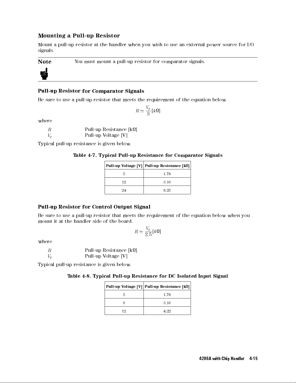
Mounting
a
Pull-up
Resistor
Mount
signals
.
Note
Pull-up
Be
sure
where
R
V
p
Typical
a
pull-up
Resistor
to
use
pull-up
resistor
You
must mount
for
a
pull-up
Pull-up
Pull-up
resistance
T
able
4-7.
at
the
handler
a pull-up
Comparator
resistor
that
Resistance
V
oltage
is
given
below
Typical
Pull-up
Pull-up
when
you
wish
to use
resistor for
comparator
Signals
meets
the
requirement
V
R
'
3
p
[
k
]
[k]
[V]
.
Resistance
V
oltage
[V]
Pull-up
Resistance
5 1.78
12 3.16
an external
of
for
Comparator
signals
the
[k]
power source
.
equation
Signals
for I/O
below.
24 8.25
Pull-up Resistor
Be
sure
to
use
mount
it
at
the
for
a
pull-up
handler
Control
resistor
side
of
Output
that
the
board.
meets
where
R
V
p
Pull-up
Pull-up
Resistance
V
oltage
[V]
Typical pull-up resistance is given below
Table 4-8. Typical Pull-up Resistance for DC Isolated Input Signal
Pull-up V
oltage [V]
5 1.78
9 3.16
12 4.22
Signal
R
[k]
.
the
requirement
V
p
[
'
k
]
2
:
5
Pull-up Resistance [k]
of
the
equation
below
when you
4286A with Chip Handler 4-15
Page 62
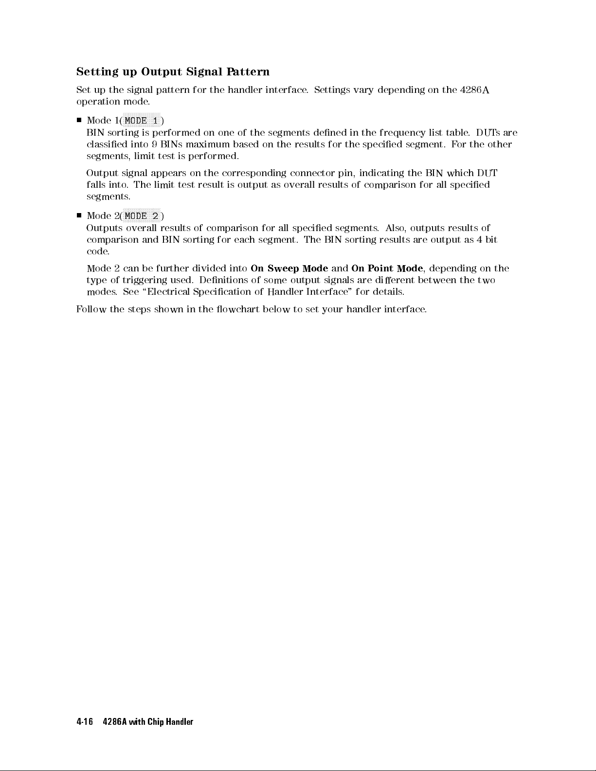
Setting
Set
up
the
operation
Mode
1(
BIN sorting
classied into
segments,
up
Output
signal
mode
.
N
N
N
N
N
N
N
N
N
N
N
NN
NN
NN
MODE
1
is performed
9 BINs
limit test
pattern
NN
N
)
is
Signal
for
the
on one
maximum
performed.
P
attern
handler
of
the
based
interface
segments
on
the
.
Settings vary
dened
results
for
in
the
depending on
the
frequency
specied
list
segment.
the 4286A
table
.
DUT
F
or
the
sare
other
Output
falls
into
segments
Mode
Outputs
comparison
code
.
Mode
type
of
modes
F
ollow the
signal
.
The
.
N
NN
NN
N
N
N
N
N
N
MODE
2(
overall
2
can
triggering
.
See
steps
appears
limit
test
N
N
N
N
N
N
N
N
N
2
)
results
and
BIN
be further
used.
\Electrical
shown
on
the
corresponding
result
of
comparison
sorting
for
divided into
Denitions
Specication
in
the
owchart
is
output
as
for all
each segment.
On
Sweep
of
some
of
Handler
below
connector
overall
pin,
results
of
specied segments
The BIN
Mode
output
Interface
to
set
sorting results
and
On
signals are
"
your
handler
indicating
comparison
.Also
P
oint
dierent
for
details
interface
the
,
outputs
are
Mode
.
BIN
which
for
all
results
output
,
depending
between
.
DUT
specied
of
as
4
on
the
two
bit
the
4-16 4286A with Chip Handler
Page 63
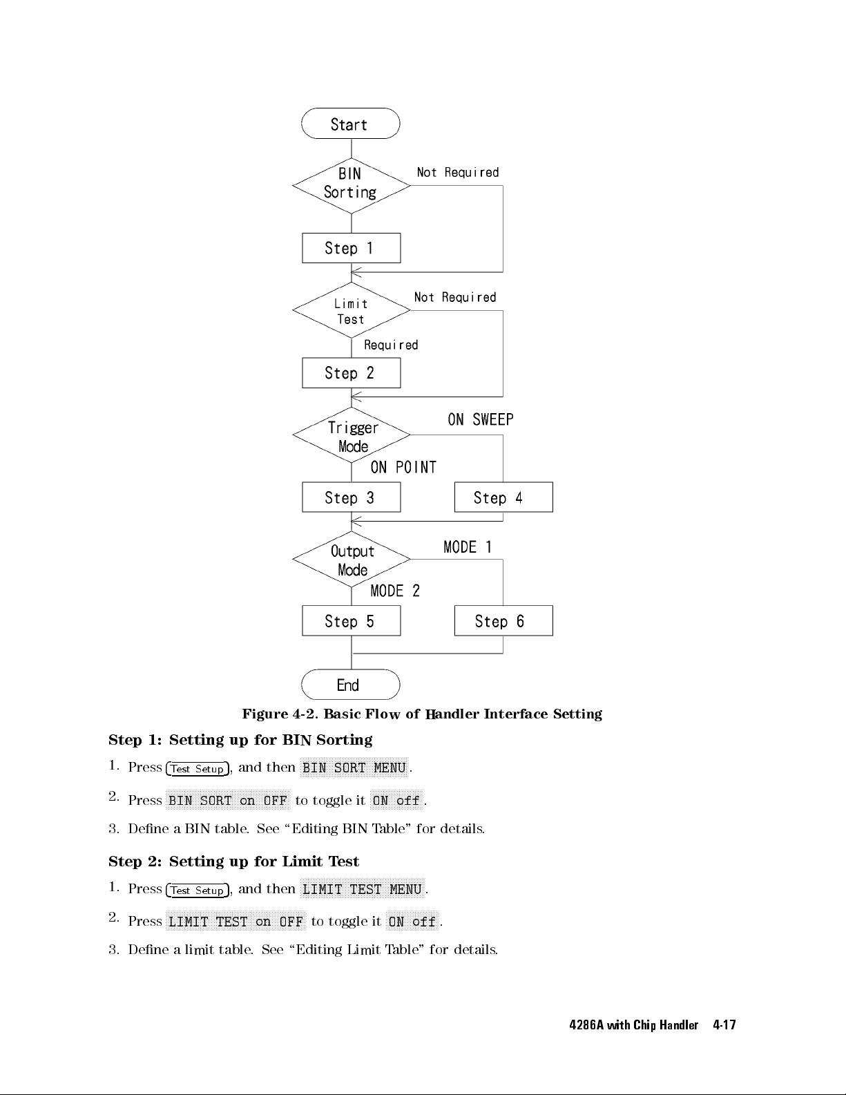
Figure
4-2.
Basic
Flow
of
Handler
Interface
Setting
Step 1:
1.
Press
2.
Press
3. Dene a BIN table
Step 2: Setting up for Limit T
1.
Press
2.
Press
Setting
4
Test Setup
NNNNN
NNNNNNNNNNNNNNNNNNNNNNNNN
BIN SORT on OFF
up
for
5
, and then
NNNNNNNNNNNNNNNNN
BIN
to toggle it
. See \Editing BIN
4
Test Setup
5
, and then
NNNNNNNNNNNNNNNNNNNNNNNNNNNNNNNNNNNNNNNNNNNNNNNNNNNNN
LIMIT TEST on OFF
Sorting
NNNNNNNNNNNNNNNNNNN
N
NNNNNNNNNNNNNNNNNNNNN
BIN SORT MENU
NNNNN
NNNNNNNNNNNNNNN
ON off
Table" for details
est
NNNNNN
NNNNNNNNNNNNNNNNNNNNNNNNN
NNNNNNNNNNNNNNNN
LIMIT TEST MENU
NNNNNNNNNNNNNNNNNNNN
to toggle it
ON off
.
.
.
.
.
3. Dene a limit table. See \Editing Limit Table" for details.
4286A with Chip Handler 4-17
Page 64
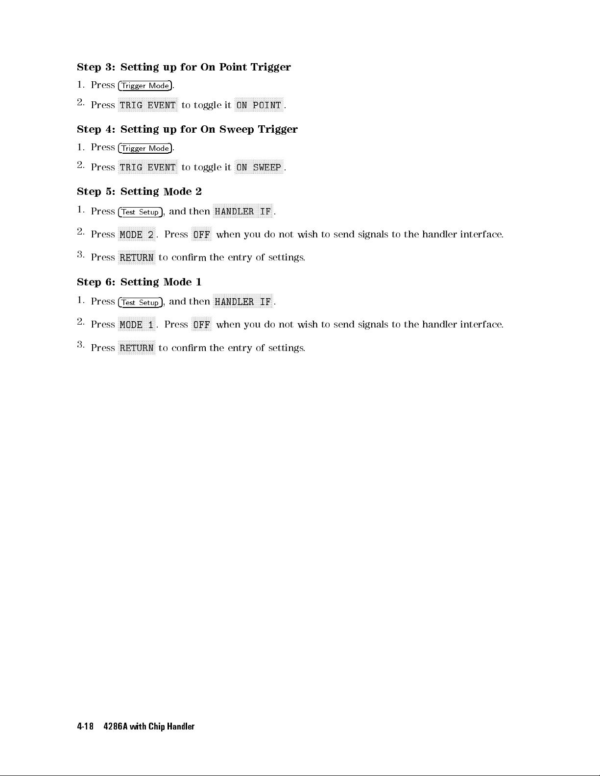
Step
3: Setting
up for
On
P
oint
Trigger
1.
Press
2.
Press
Step
1.
Press
2.
Press
Step
1.
Press
2.
Press
3.
Press
Step
1.
Press
2.
Press
3.
Press
4
N
N
TRIG
4:
Setting
4
N
N
TRIG
5:
Setting
4
N
N
MODE
N
N
RETURN
6:
Setting
4
N
NN
MODE
N
N
RETURN
T
rigger Mo
N
N
N
N
N
N
N
N
NN
NN
T
rigger
NN
NN
NN
N
N
N
N
N
T
est Setup
N
N
N
N
N
N
N
N
N
N
N
N
N
N
N
N
N
N
N
N
N
NN
T
est
Setup
NN
N
N
N
N
N
N
N
N
N
N
N
N
N
N
N
N
N
N
N
NN
NN
NN
NN
EVENT
Mo
N
N
N
N
N
N
N
N
EVENT
N
N
N
N
N
N
N
2
.
NN
NN
N
N
N
N
N
N
N
N
N
1
.
N
N
N
NN
NN
5
.
de
NN
N
N
N
N
N
N
N
N
up for
5
.
de
N
N
N
N
NN
NN
NN
N
Mode
5
, and
Press
to
conrm
Mode
5
,
and
Press
to
conrm
to
toggle
On Sweep
to
toggle it
2
then
N
N
N
N
N
N
N
N
N
OFF
1
then
N
NN
NN
N
N
N
N
OFF
it
N
NN
NN
N
N
N
N
N
N
HANDLER
N
N
when
the
entry
N
N
N
N
N
N
N
N
N
N
N
HANDLER
N
N
when
the
entry
N
N
N
N
N
N
ON
N
NN
ON
N
N
N
NN
N
N
NN
N
N
NN
N
N
N
N
N
NN
NN
POINT
Trigger
NN
N
N
N
N
N
N
SWEEP
N
N
N
N
N
N
N
NN
IF
you
of
NN
N
N
N
N
N
N
IF
you
of
NN
NN
NN
NN
NN
N
N
N
N
N
N
N
N
N
N
N
N
NN
NN
NN
N
.
do
not
settings
N
N
N
N
N
N
N
.
do
not
settings
N
.
N
.
wish
to
send
.
wish
.
to
send
signals
signals
to
to
the
the
handler
handler
interface
interface
.
.
4-18 4286A with Chip Handler
Page 65
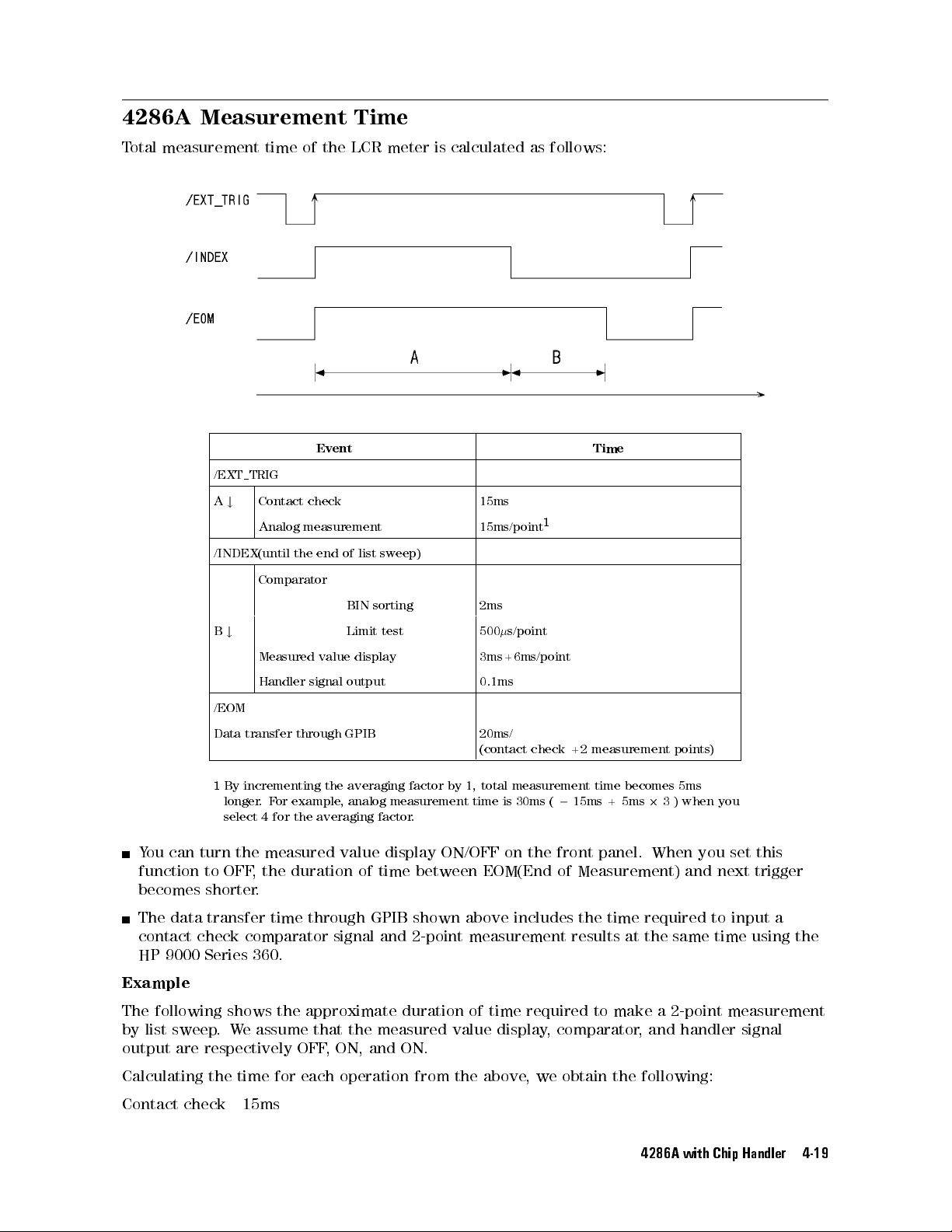
4286A Measurement
T
otal
measurement
time
of the
Event Time
/EXT TRIG
A
Contact
#
Analog
check
measurement
Time
LCR meter
is calculated
15ms
15ms/point
as follows:
1
/INDEX(until
the
end
of
list
sweep)
Comparator
BIN
sorting
B
#
Measured
Handler
Limit
value
display
signal output
test
2ms
500
s/point
3ms+6ms/point
0.1ms
/EOM
Data
transfer
1
By
incrementing
longer
select
.
F
4for
or
through
example
GPIB
the
,
averaging
analog
the averaging
factor
measurement
factor.
20ms/
(contact
by
1,
total measurement
time
is
check
30ms
(=
+2
15ms +
measurement
time becomes
5ms
2
points)
3)
5ms
when
you
You can turn the measured value display ON/OFF on the front panel. When you set this
function to OFF
becomes shorter
, the duration of time between EOM(End of Measurement) and next trigger
.
The data transfer time through GPIB shown above includes the time required to input a
contact check comparator signal and 2-point measurement results at the
same time using the
HP 9000 Series 360.
Example
The following shows the approximate duration of time required to make a 2-point measurement
by list sweep.We assume that the measured value display, comparator, and handler signal
output are respectively OFF, ON, and ON.
Calculating the time for each operation from the above, we obtain the following:
Contact check 15ms
4286A with Chip Handler 4-19
Page 66
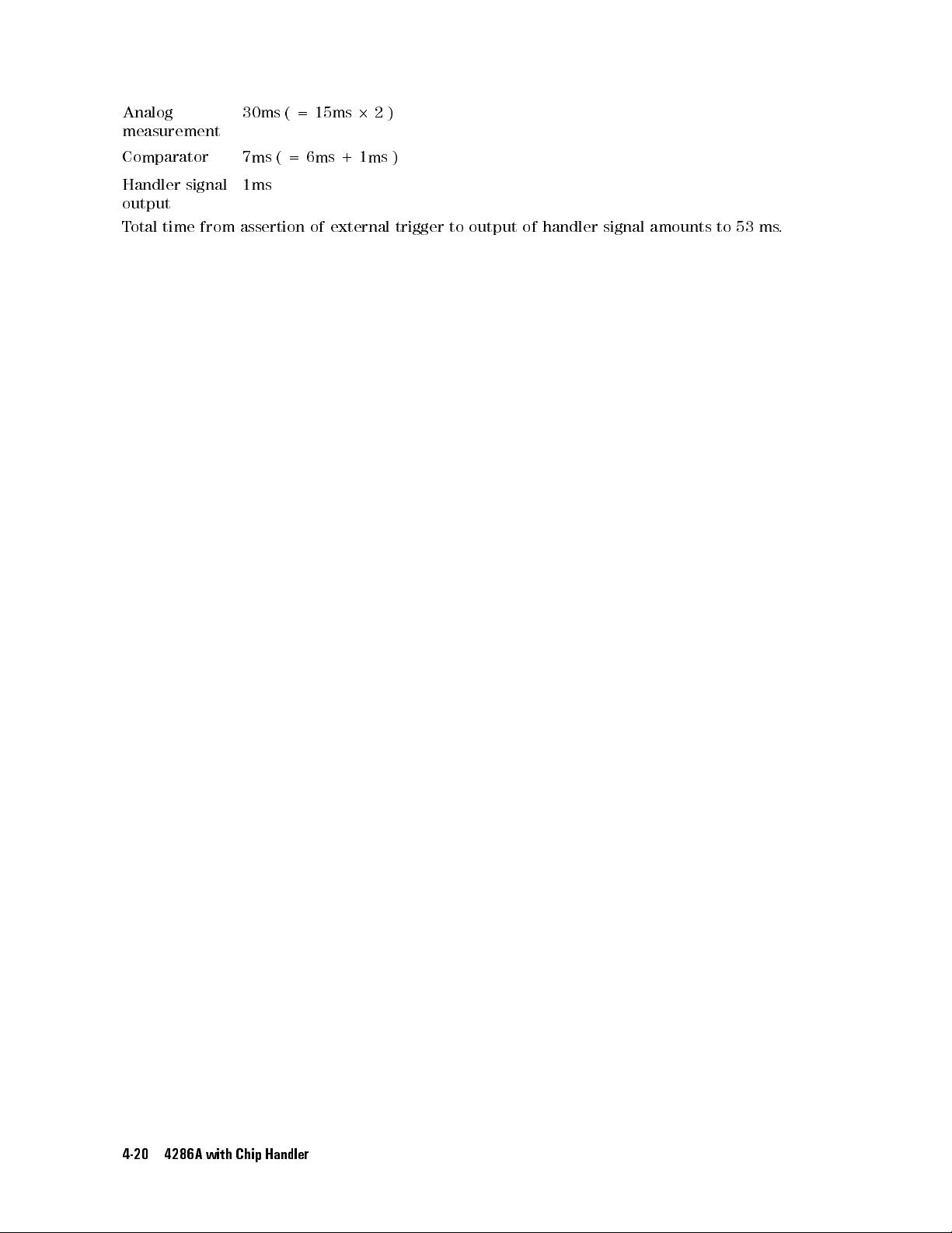
Analog
measurement
Comparator
30ms
7ms
(
(=
=
15ms
6ms +
2
2)
1ms )
Handler signal
output
T
otal
time from
1ms
assertion of
external trigger
to output
of
handler
signal
amounts
to
53
ms
.
4-20 4286A with Chip Handler
Page 67
Electrical Specication
The
handler
allows
the
4286A
Using
This
signal,
these
section
timing
and
and
timing
interface
control
handler
signals
provides
diagram
sends
signals
interface.
you
can
the
pin assignment
results of
for measurements
congure
of these
of Handler
comparison from
and handler
a
highly
ecient chip
of the
handler interface
signals.
Interface
the 4286A
operation to
handling system.
to the
handler interface
be exchanged
connector,
description
and
between
of
each
4286A with Chip Handler 4-21
Page 68
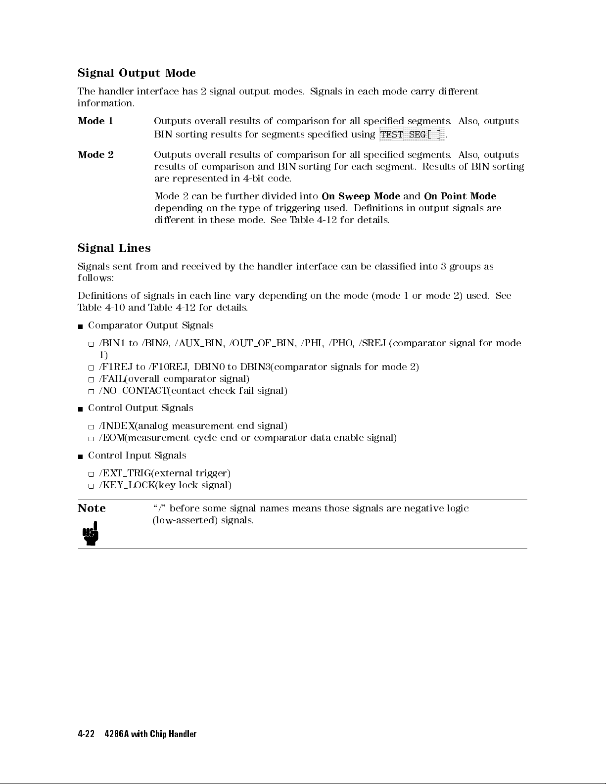
Signal
The
Output
handler
information.
Mode
1
Mode
2
Mode
interface
Outputs
BIN
Outputs
results
are
Mode
depending
dierent
has
2
signal
overall
sorting
results
overall
of
comparison
represented
2
can
be further
on
in
these
results
results
in
the
output
for
segments
and
4-bit
divided into
type of
mode
modes
.
Signals
of
comparison for
specied
of
comparison
BIN
sorting
code
.
triggering used.
.
See T
able 4-12
in each
all specied
using
for all
for
each segment.
On Sweep
Denitions in
for details
mode carry
segments.
N
N
N
N
N
N
N
N
N
N
N
NN
NN
N
TEST
NN
NN
NN
NN
SEG[
dierent
NN
N
N
N
N
N
N
N
N
]
specied segments
Results of
Mode
and
On
P
output signals
.
N
.
. Also
oint
Also,
outputs
, outputs
BIN sorting
Mode
are
Signal
Signals
Lines
sent
from
follows:
Denitions
T
able
4-10
of
and
Comparator
/BIN1
to
/BIN9,
1)
/F1REJ
/F
to
AIL(overall
/NO CONT
Control
Output
/INDEX(analog
/EOM(measurement
Control
Input Signals
/EXT TRIG(external
/KEY LOCK(key
Note
and
received
signals
Output
in
T
able
4-12
/A
/F10REJ
each
Signals
UX
,
comparator
A
CT(contact
Signals
measurement
lock
\/"
before
(low-asserted)
line
for
details
BIN,
DBIN0
check
cycle
trigger)
signal)
some
by
the
handler
vary
depending
.
/OUT
to
OF BIN,
DBIN3(comparator
signal)
fail
signal)
end
signal)
end
or comparator
signal
signals
names means
.
interface
on
the
/PHI,
/PHO
data enable
those signals
can
mode
,
signals
be
classied
(mode
/SREJ
for
signal)
into
1
or mode
(comparator
mode 2)
are negative
3
groups
2) used.
signal
logic
as
See
for mode
4-22 4286A with Chip Handler
Page 69
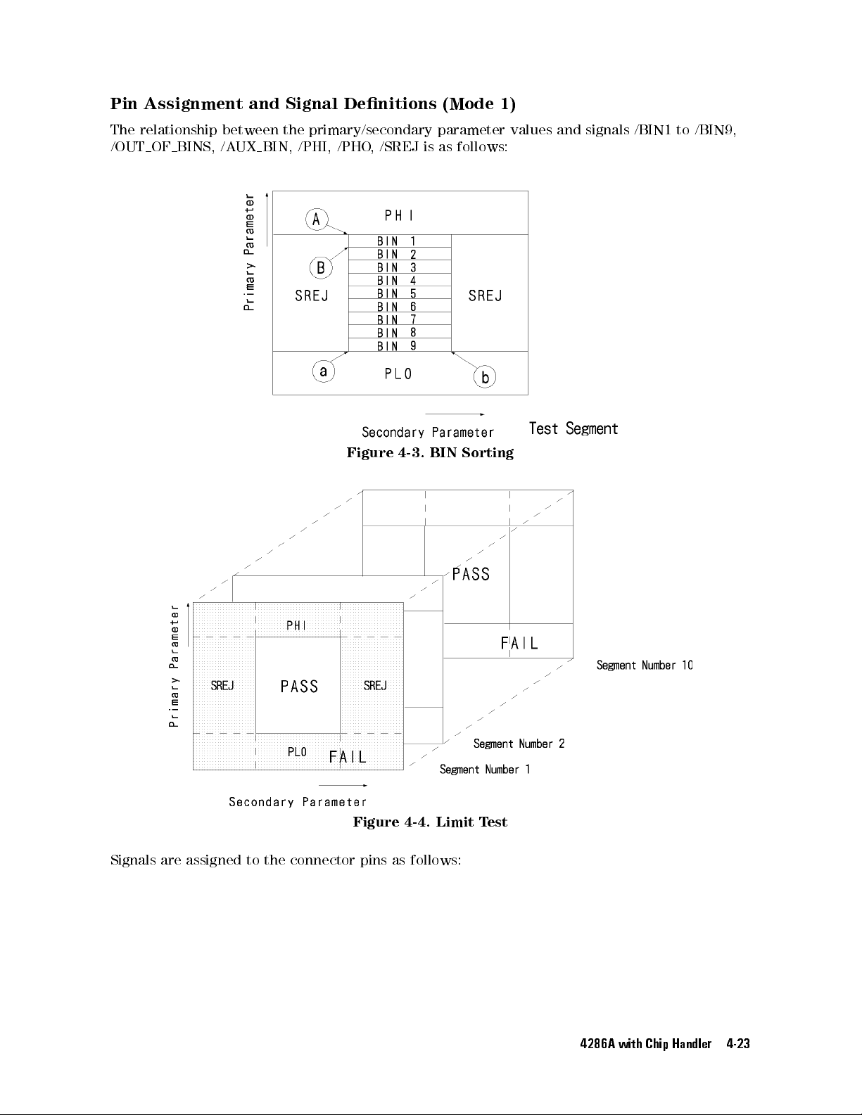
Pin
Assignment
The
relationship
/OUT OF BINS,
and
between
UX
BIN,
/A
Signal
the
/PHI,
Denitions
primary/secondary
/PHO
,
/SREJ
(Mode
parameter
is
as follows:
1)
values
and
signals
/BIN1
to /BIN9,
Signals are
Figure 4-3.
BIN Sorting
Figure 4-4. Limit T
assigned to the connector pins as follows:
est
4286A with Chip Handler 4-23
Page 70
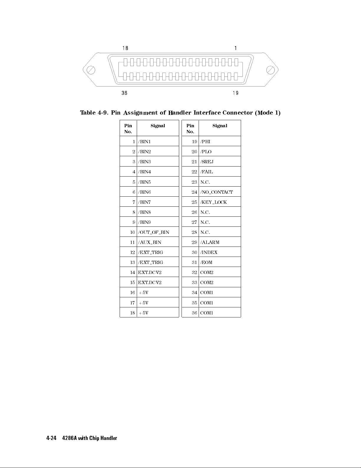
T
able
4-9.
Pin
Assignment
of
Handler
Interface
Connector (Mode
1)
Pin
No
.
Signal
1 /BIN1
2 /BIN2
3 /BIN3
4 /BIN4
5 /BIN5
6 /BIN6
7 /BIN7
8 /BIN8
9 /BIN9
10 /OUT OF BIN
11 /AUXBIN
12 /EXT TRIG
13 /EXT TRIG
14 EXT
.DCV2
15 EXT
.DCV2
16 +5V
Pin
No
.
19 /PHI
20 /PLO
21 /SREJ
22 /F
AIL
23 N.C.
24 /NO CONTA
25 /KEY LOCK
26 N.C.
27 N.C.
28 N.C.
29 /ALARM
30 /INDEX
31 /EOM
32 COM2
33 COM2
34 COM1
Signal
CT
4-24 4286A with Chip Handler
17 +5V
18 +5V
35 COM1
36 COM1
Page 71
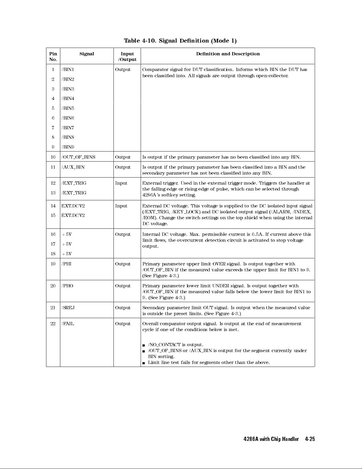
T
able 4-10.
Signal Denition
(Mode
1)
Pin
No.
Signal Input
/Output
1 /BIN1 Output Comparator
2 /BIN2
been classied
3 /BIN3
4 /BIN4
5 /BIN5
6 /BIN6
7 /BIN7
8 /BIN8
9 /BIN9
10 /OUT OF BINS Output Is
11 /AUXBIN Output Is
output
output
secondary
12 /EXT TRIG Input External
the
13 /EXT TRIG
falling
4286A
's
softkey
14 EXT.DCV2 Input External DC
15 EXT
.DCV2
(/EXT TRIG,
/EOM).
Change
DC voltage
signal for
into.
if
the
primary
if
the
primary
parameter
trigger
.
edge or
voltage
/KEY
the
.
Denition
DUT classication.
All
signals
parameter
parameter
has
not
Used
in
the
rising edge
setting.
.
This
voltage
LOCK)
and
switch
settings
and Description
are
output
has
has
been
classied
external
of pulse
is
supplied
DC
isolated
on
Informs which
through
no
been
been
classied into
into
trigger
mode
, which
can
to
output
the
top
shield
open-collector
classied
any
BIN.
.
Triggers
be
selected
the
DC
isolated
signal
(/ALARM,
when
BIN the
into
any
a
BIN
the
through
using
DUT has
.
BIN.
and
the
handler
input
/INDEX,
the
internal
at
signal
16 +5V Output Internal
17 +5V
limit
output.
ows
DC
,
voltage
the
overcurrent
.
Max.
permissible
detection
circuit
is
0.5A.
is
activated
If current
to
stop
above
voltage
18 +5V
19 /PHI Output Primary
/OUT OF BIN
(See
20 /PHO Output Primary
/OUT OF BIN
9.
21 /SREJ Output Secondary
is
parameter
Figure
parameter
(See Figure
parameter
outside the
if
the measured
4-3
.)
if
the
4-3
.)
preset
upper
lower
limit
measured
limit
limits
limit
O
VER
value exceeds
UNDER
value
OUT
signal.
.
(See
Figure
signal.
signal.
falls
Is
4-3
Is
the
below
output
.)
output
upper
Is output
the
lower
when
together
limit
with
for
together with
limit for
the
measured
BIN1
BIN1 to
22 /FAIL Output Overall comparator output signal. Is output at the end of measurement
cycle if one of the conditions below is met.
/NO CONTACT is output.
/OUT OF BINS or /AUXBIN is output for the segment currently under
BIN sorting.
Limit line test fails for segments other than the above
.
this
to
value
9.
4286A with Chip Handler 4-25
Page 72
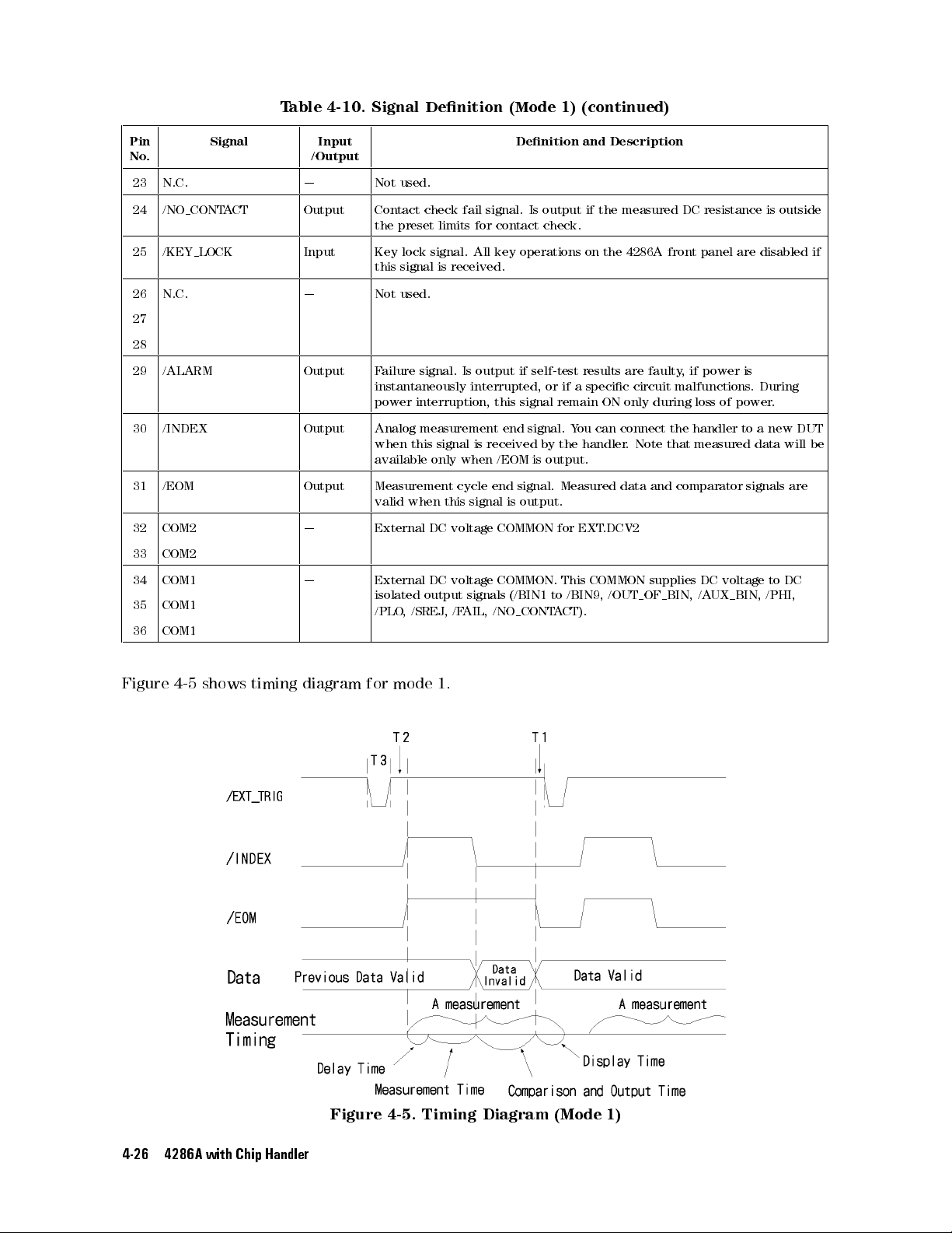
T
able 4-10.
Signal Denition
(Mode
1)
(continued)
Pin
No.
23 N.C. | Not
24 /NO CONT
25 /KEY LOCK Input Key
26 N.C. | Not
Signal Input
/Output
A
CT
Output Contact
the
this
used.
check
preset
lock
signal is
used.
signal.
27
28
29 /ALARM Output F
ailure
signal.
instantaneously
power
interruption, this
30 /INDEX Output Analog
when
this
available
measurement
only
31 /EOM Output Measurement
valid when
32 COM2 | External
DC
33 COM2
34 COM1 | External
35 COM1
isolated
/PLO
,
/SREJ
DC
output
36 COM1
fail
limits
All
received.
Is
interrupted,
signal
is
when
cycle
this signal
voltage
voltage
signals
,
/F
AIL,
Denition
signal.
for contact
key
operations
output
if
signal
end
received
/EOM
end
signal.
is output.
COMMON
COMMON.
(/BIN1
CONT
/NO
Is
output
check.
self-test
or
signal.
by
is
output.
to
A
and Description
if the
on
the
results
if
a
specic
remain
ON
Y
ou
can
connect
the handler
Measured
for
This
/BIN9,
EXT
.DCV2
COMMON
/OUT
data
CT).
measured DC
4286A
front
are
faulty
,
circuit
only
malfunctions
during
the handler
.
Note
that
and
comparator
supplies
OF BIN,
resistance is
panel
if
power
loss
of
measured
DC voltage
/A
UX
are
is
. During
power
to a
data
signals
BIN,
outside
disabled if
.
new
DUT
will
are
to
DC
/PHI,
be
Figure
4-5 shows
timing
diagram
for
mode
1.
Figure 4-5. Timing Diagram (Mode 1)
4-26 4286A with Chip Handler
Page 73
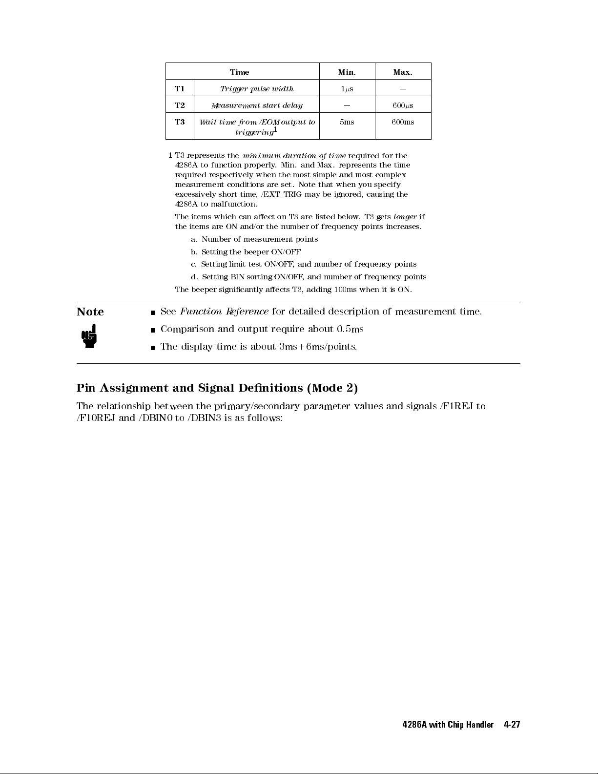
Time Min. Max.
Note
T1
T2
T3
1
T3
4286A
Measurement
Wait
represents
to
function
required respectively
measurement
excessively
4286A to
The
the
items
items
malfunction.
which
are
a. Number
b
.
Setting
c
.
Setting
d.
Setting
The
beeper
See
Function
Comparison
The
display
Trigger
pulse
time from
triggering
the
minimum
properly
conditions
short
time
can
ON
and/or
of measurement
the
beeper
limit test
BIN
sorting
signicantly
Reference
and
output
time
is
about 3ms+6ms/points
width
start
delay
/EOM output
1
duration
.
Min.
when the
are
set.
TRIG
,
/EXT
aect
on
T3
the
number
ON/OFF
ON/OFF,
ON/OFF
aects
for detailed
require
to
of
and
Max. represents
most simple
Note
that
may
be
are
listed
of frequency
points
and
number
,
and
number
T3,
adding
about 0.5ms
1
s
| 600
5ms 600ms
time
required
for
the time
and most
when
ignored,
below
you
causing
.
T3
complex
specify
gets
points increases
of
frequency
of
frequency
100ms
when
it
description of
.
|
s
the
the
longer
if
.
points
points
is
ON.
measurement time
.
Pin
Assignment
The
relationship
/F10REJ
and
between
/DBIN0
and
to
Signal
the
/DBIN3
Denitions
primary/secondary
is
as
follows:
(Mode
parameter
2)
values
and
signals
/F1REJ
to
4286A with Chip Handler 4-27
Page 74
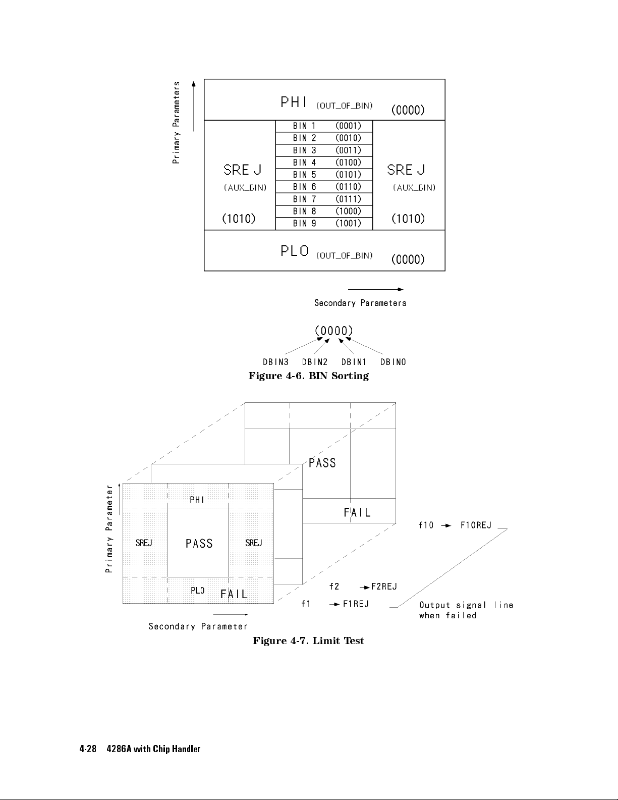
Figure
4-6.
BIN
Sorting
4-28 4286A with Chip Handler
Figure 4-7. Limit T
est
Page 75
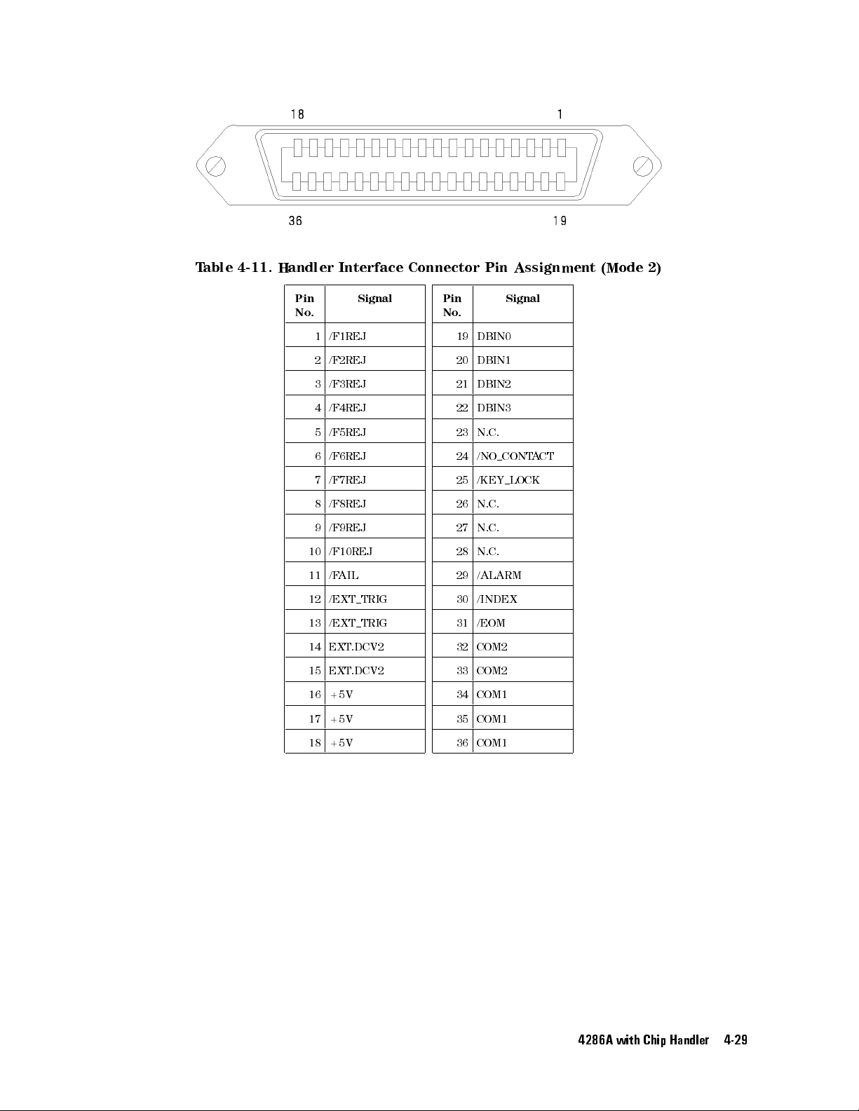
T
able
4-11.
Handler
Interface
Connector
Pin
Assignment
(Mode 2)
Pin
No
.
1 /F1REJ
2 /F2REJ
3 /F3REJ
4 /F4REJ
5 /F5REJ
6 /F6REJ
7 /F7REJ
8 /F8REJ
9 /F9REJ
10 /F10REJ
11 /F
AIL
12 /EXT TRIG
13 /EXT TRIG
14 EXT
15 EXT
16 +5V
Signal
.DCV2
.DCV2
Pin
No
.
19 DBIN0
20 DBIN1
21 DBIN2
22 DBIN3
23 N.C.
24 /NO CONTA
25 /KEY LOCK
26 N.C.
27 N.C.
28 N.C.
29 /ALARM
30 /INDEX
31 /EOM
32 COM2
33 COM2
34 COM1
Signal
CT
17 +5V
18 +5V
35 COM1
36 COM1
4286A with Chip Handler 4-29
Page 76
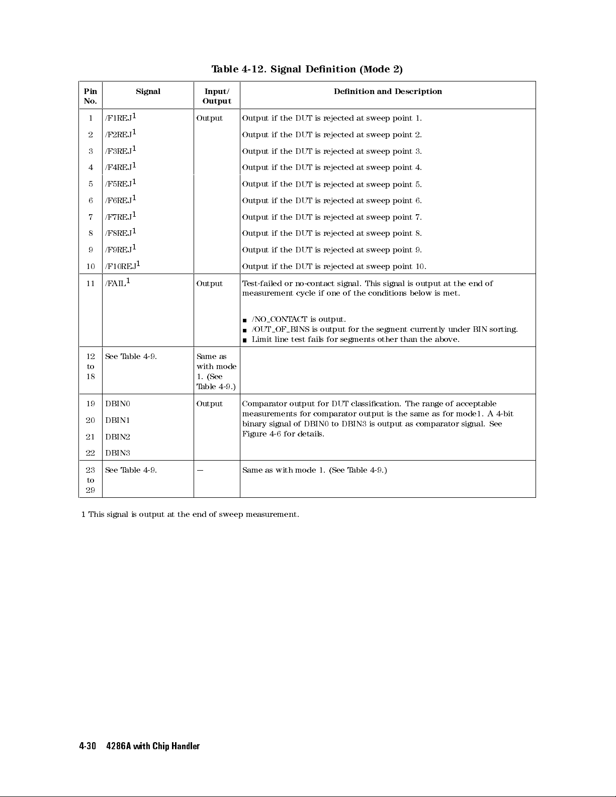
T
able 4-12.
Signal Denition
(Mode
2)
Pin
No.
1 /F1REJ
2 /F2REJ
3 /F3REJ
4 /F4REJ
5 /F5REJ
6 /F6REJ
7 /F7REJ
8 /F8REJ
9 /F9REJ
10 /F10REJ
11 /F
AIL
12
See
T
to
18
Signal Input/
1
Output Output
1
1
1
1
1
1
1
1
1
1
able
4-9
.
Output T
Same
with
1.
T
Output
as
mode
(See
able
4-9
Output if
Output
Output
Output
Output
Output
Output
Output
Output
est-failed
measurement
/NO CONT
/OUT OF BINS
Limit
.)
if the
the DUT
if the
if
the
if
the
if
the
if
the
if
the
if
the
if
the
or
line
DUT is
is rejected
DUT
is
DUT
is
DUT
is
DUT
is
DUT
is
DUT
is
DUT
is
DUT
is
no-contact
cycle
if
A
CT
is
output.
is output
test
fails
Denition
rejected at
at sweep
rejected
rejected
rejected
rejected
rejected
rejected
rejected
at
at
at
at
at
at
at
rejected at
signal.
one
of
the
for the
for segments
and Description
sweep point
point
sweep
point
sweep
point
sweep
point
sweep
point
sweep
point
sweep
point
sweep
point 9.
sweep point
This
signal
conditions
is
below
segment currently
other than
1.
2.
3.
4.
5.
6.
7.
8.
10.
output
the
at
is
met.
above
the
under
.
end
BIN
of
sorting.
19 DBIN0 Output Comparator
20 DBIN1
21 DBIN2
measurements
binary
Figure
22 DBIN3
23
See
T
able
4-9
.
| Same
as
to
29
1
This
signal is
output at
the end
of
sweep
measurement.
signal
4-6
with
output
of
for
for
DBIN0
details
mode
for
DUT
comparator
to
DBIN3
.
1.
(See
T
classication.
output
is
is
output
able
4-9
.)
The
range
the
same
as comparator
as
of
acceptable
for
mode1.
signal.
A
See
4-bit
4-30 4286A with Chip Handler
Page 77
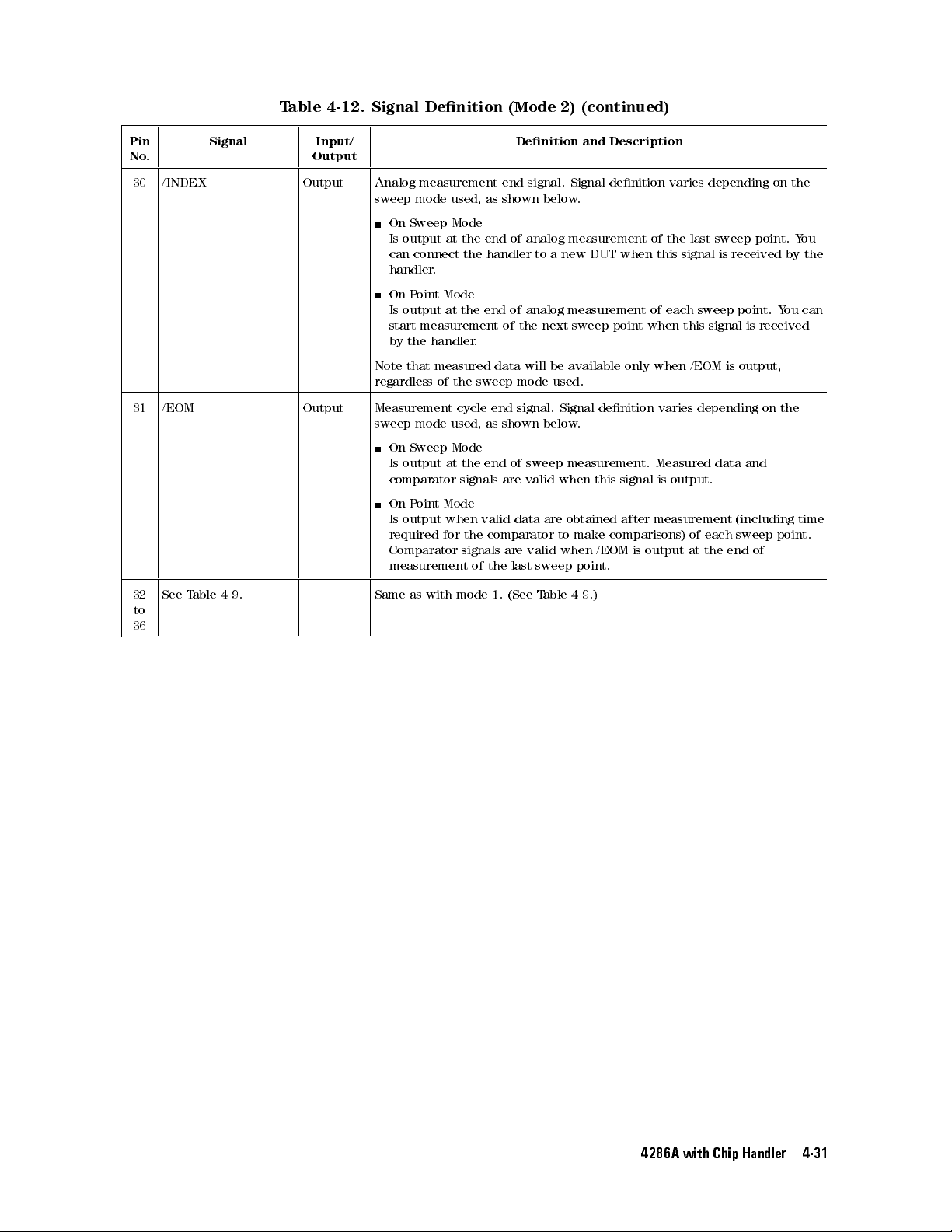
T
able 4-12.
Signal Denition
(Mode
2)
(continued)
Pin
No.
30 /INDEX Output Analog
Signal Input/
Output
measurement end
sweep mode
On
Sweep
Is
output at
can
connect
handler
.
On
Point
Is
output
start
measurement
by
the handler
Note
that
measured
regardless
31 /EOM Output Measurement
sweep
mode
On Sweep
Is
output
comparator
On
P
oint
Is
output
required
Comparator signals
measurement
used, as
Mode
the end
the
Mode
at
the
of
the
cycle
used,
Mode
at
the
signals are
Mode
when
for
the
shown
of analog
handler
end
of
of
.
data
sweep
end
as
shown
end
of
valid
comparator
are
of
the
last
Denition
signal. Signal
below
to
a
new
analog
the
next sweep
will
be
mode
used.
signal.
Signal
below
sweep
valid when
data
are
to
valid
when
sweep
and Description
denition varies
.
measurement of
DUT
when
measurement
point when
available
only
denition
.
measurement.
this signal
obtained
make
after
comparisons)
/EOM
is
output
point.
depending on
the
last
this
signal
of
each
sweep
this signal
when
/EOM
varies
depending
Measured
is
output.
measurement
of
each
at
the
sweep
point.
is
received
point.
is received
is
output,
on
data
and
(including time
sweep
end
of
the
Y
by
Y
ou
the
point.
ou
the
can
32
to
36
See
T
able 4-9
.
| Same
as
with mode
1.
(See
T
able
4-9
.)
4286A with Chip Handler 4-31
Page 78
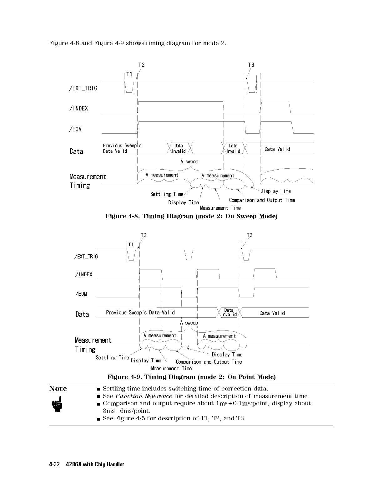
Figure
4-8 and
Figure 4-9
shows
timing
diagram
for
mode
2.
Note
Figure
Figure 4-9. Timing Diagram (mode 2: On P
4-8.
Timing
Diagram
(mode
2:
On
Sweep
Mode)
oint Mode)
Settling time includes switching time of correction data.
See
Function R
eference
for detailed description of measurement time
Comparison and output require about 1ms+0.1ms/point, display about
3ms+6ms/point.
See Figure 4-5 for description of T1, T2, and T3.
.
4-32 4286A with Chip Handler
Page 79
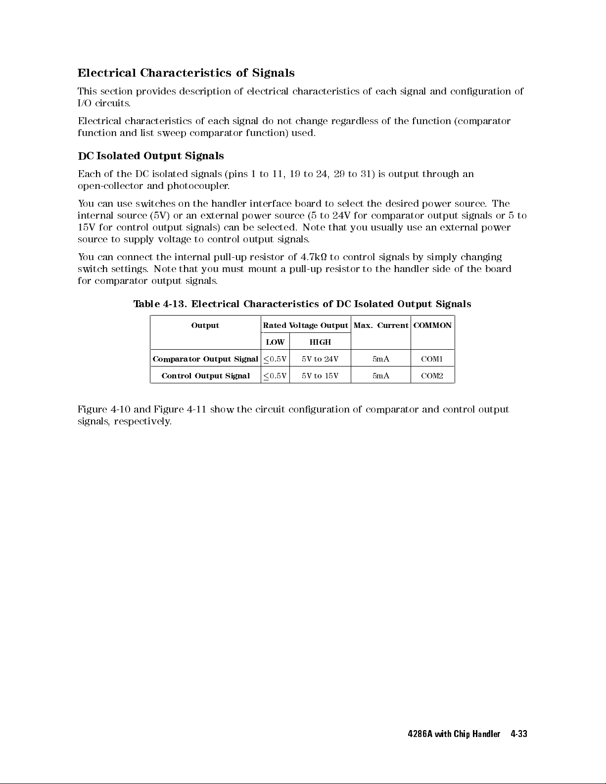
Electrical
This
section
I/O
circuits
.
Characteristics
provides
description
of
Signals
of
electrical
characteristics
of
each
signal
and conguration
of
Electrical
function
DC
Each
characteristics
and
Isolated
of
the
DC
open-collector
Y
ou
can
use
switches
internal
15V
source
Y
ou
switch
for
source
for
control
to
supply
can
connect
settings
comparator
T
list
sweep
Output
isolated
and
(5V)
output
voltage
the internal
.
Note
output
able
4-13.
Comparator
Control
of
each
comparator
Signals
signals
photocoupler
on
the handler
or
an
(pins 1
.
external
signals) can
to control
pull-up resistor
that
you
must mount
signals
.
Electrical
Output Rated
Output
Output
Signal
signal
do
not change
function)
to 11,
interface board
power
source
be selected.
output signals
of 4.7k
a pull-up
Characteristics
V
LO
W
0.5V
0.5V
Signal
used.
19 to
(5 to
Note that
.
oltage
HIGH
5V
5V
regardless of
24, 29
to
to select
24V for
to
control
resistor
of
DC
Output
to
24V
to
15V
the function
31)
is
output
the desired
comparator output
you
usually
use
signals
to
the
handler
Isolated
Max.
Output
Current
5mA COM1
5mA COM2
through
power
an
external
by
simply
side
Signals
COMMON
(comparator
an
source
.
The
signals
or
power
changing
of
the
board
5
to
Figure
signals
4-10 and
Figure
, respectively
4-11
show
the
circuit
conguration
of
comparator
and
control
output
.
4286A with Chip Handler 4-33
Page 80
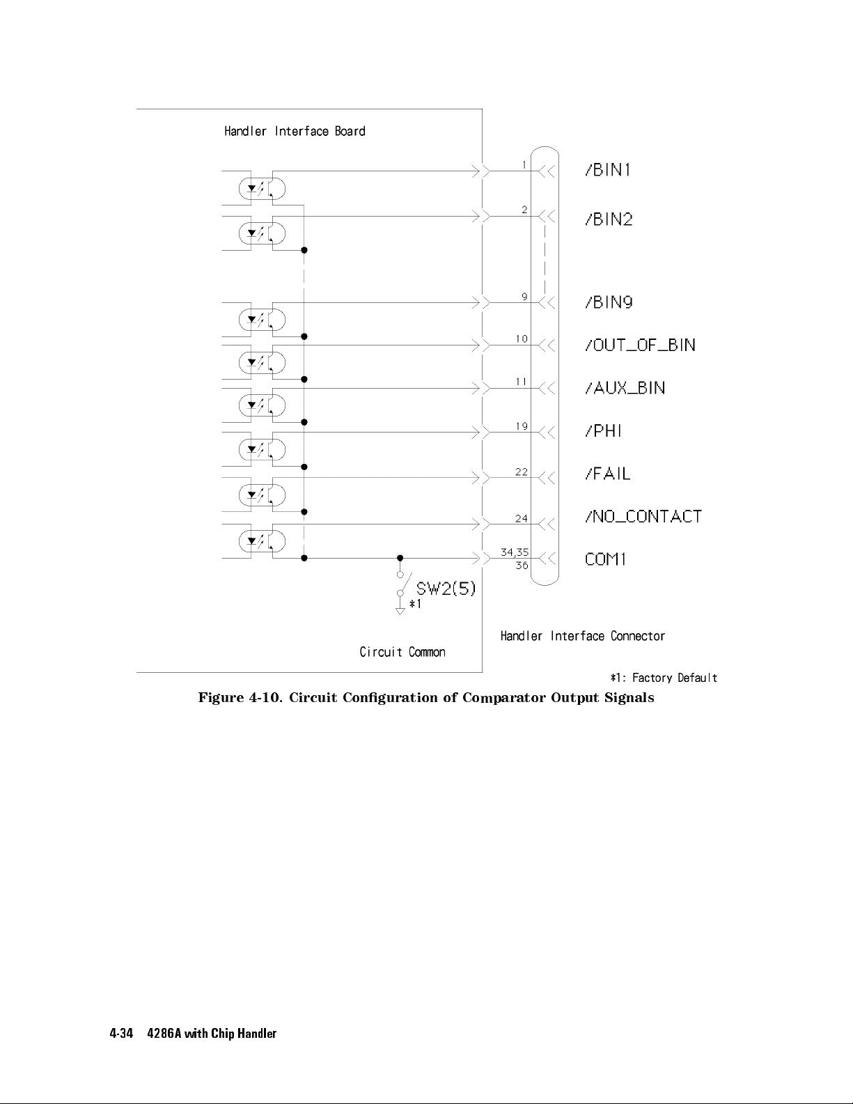
Figure
4-10.
4-34 4286A with Chip Handler
Circuit
Conguration
of
Comparator Output
Signals
Page 81

DC
Isolated
Figure
Input
4-11.
Signals
Circuit
Conguration
of
Control
Output
Signals
TRIG
DC
isolated
input
signals can
be divided
into
/EXT
and
/EXT TRIG
/EXT TRIG
triggered
softkey
(5V)
or external
select
Note
(pins 12
at
the
setting.
the desired
Use
and 13)
falling
Drive
(EXT
source
SW2
edge
voltage
.DCV2)
.)
to select
is input
or
rising
is
applied
power
the proper
to the
edge
to
source
cathode
of
the
.
(Use
pulse
anode
of
photocoupler
,
which
of
switches
photocoupler
resistor according
can
on
applied. This resistor is used to limit the trigger voltage to
See T
able 4-5 for details
.
/KEY LOCK
/KEY LOCK(pin 25) is input to the cathode of photocoupler LED
front panel are disabled when this signal is low
photocoupler
source.
LED through pins 14 and 15 by the internal (5V) or external (EXT
(Use switches on the handler interface board to select the desired source
. Drive voltage is applied to the anode of
LOCK.
/KEY
LED
.
The
be
selected
through
LED
the
handler
to the
interface
level of
the specied level.
. All keys on the 4286A
4286A
is
4286A
by
the
internal
board
anode voltage
.DCV2) power
.)
's
to
4286A with Chip Handler 4-35
Page 82
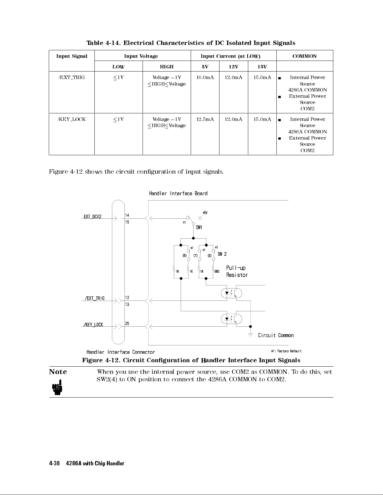
T
able 4-14.
Electrical Characteristics
of
DC
Isolated
Input
Signals
Input
/EXT TRIG
/KEY LOCK
Figure
Signal
4-12
shows
Input
V
oltage
Input
Current
(at
LOW HIGH 5V 12V 15V
1V
1V Voltage
the
circuit
conguration
V
oltage
HIGH
HIGH
0
1V
V
oltage
0
1V
V
oltage
10.0mA 12.0mA 15.0mA Internal
12.5mA 12.0mA 15.0mA Internal P
of
input
signals.
LO
W)
COMMON
Source
4286A
COMMON
External
Source
COM2
Source
4286A
COMMON
External P
Source
COM2
P
ower
P
ower
ower
ower
Figure 4-12. Circuit Conguration of Handler Interface Input Signals
Note
When you use the
SW2(4) to ON position to
4-36 4286A with Chip Handler
internal power source
connect the 4286A COMMON to COM2.
, use COM2 as COMMON. T
o do this
,set
Page 83
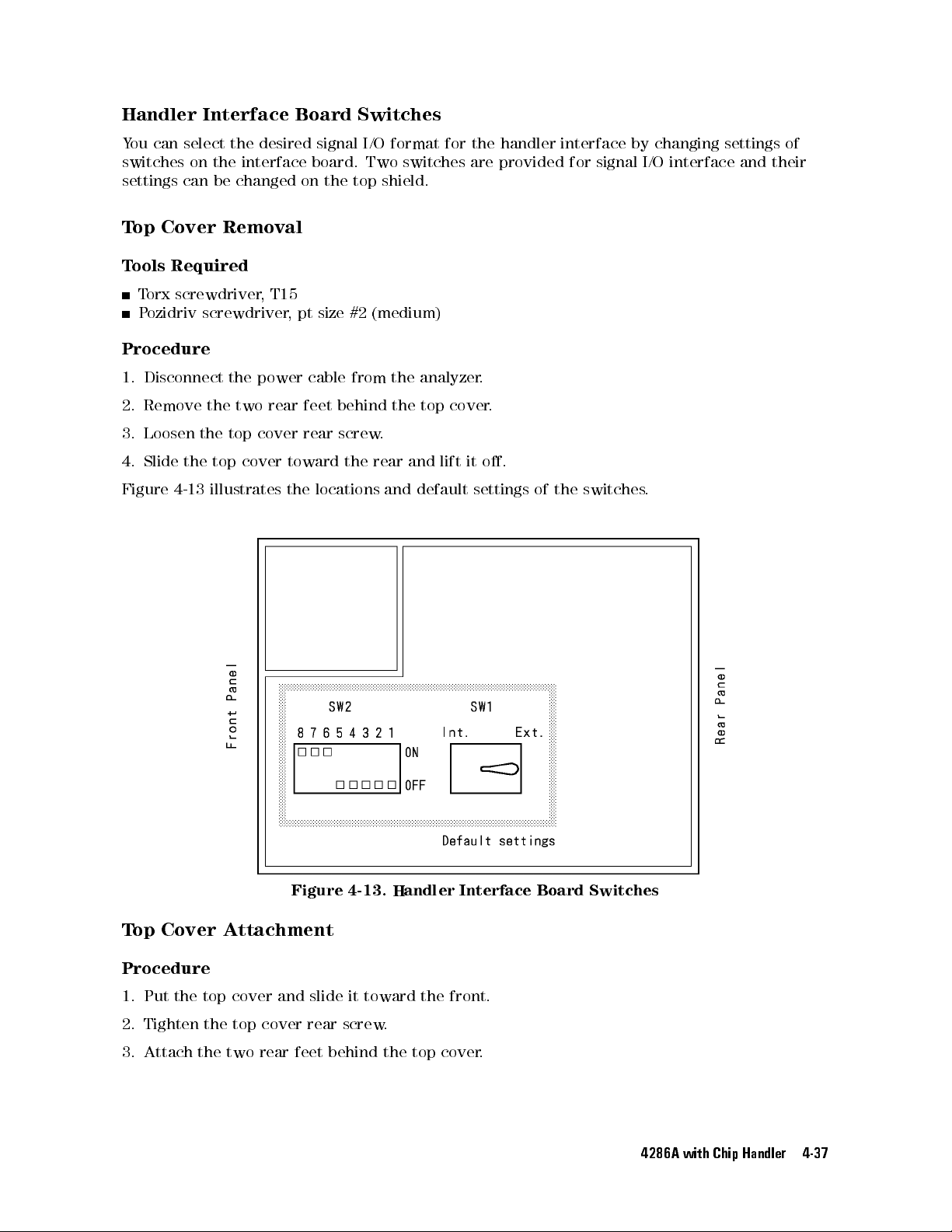
Handler
Y
ou
can
select
switches
settings
T
op Cover
T
ools
T
P
on
can
Required
orx
screwdriver
ozidriv
Procedure
1.
Disconnect
2.
Remove
3.
Loosen
4.
Slide
the
Interface
the
desired
the
interface
be
changed
Removal
,
T15
screwdriver
the
power cable
the
two rear
the
top
cover
top
cover
Board
signal
board.
on
the
,
pt
size #2
feet behind
rear
screw.
toward
Switches
I/O
format
Two
top shield.
(medium)
from the
the top
the
rear and
for
the handler
switches are
analyzer.
cover
lift
it
provided for
.
o.
interface by
signal I/O
changing settings
interface and
of
their
Figure
4-13
illustrates
the
locations
Figure 4-13. Handler Interface Board Switches
Top Cover Attachment
and
default
settings
of
the
switches
.
Procedure
1. Put the top cover and slide it toward the front.
2. Tighten the top cover rear screw.
3. Attach the two rear feet behind the top cover.
4286A with Chip Handler 4-37
Page 84
Warning
Do
not
connect
removed.
the
power
cable
to
the meter
during the
top cover
is
4-38 4286A with Chip Handler
Page 85
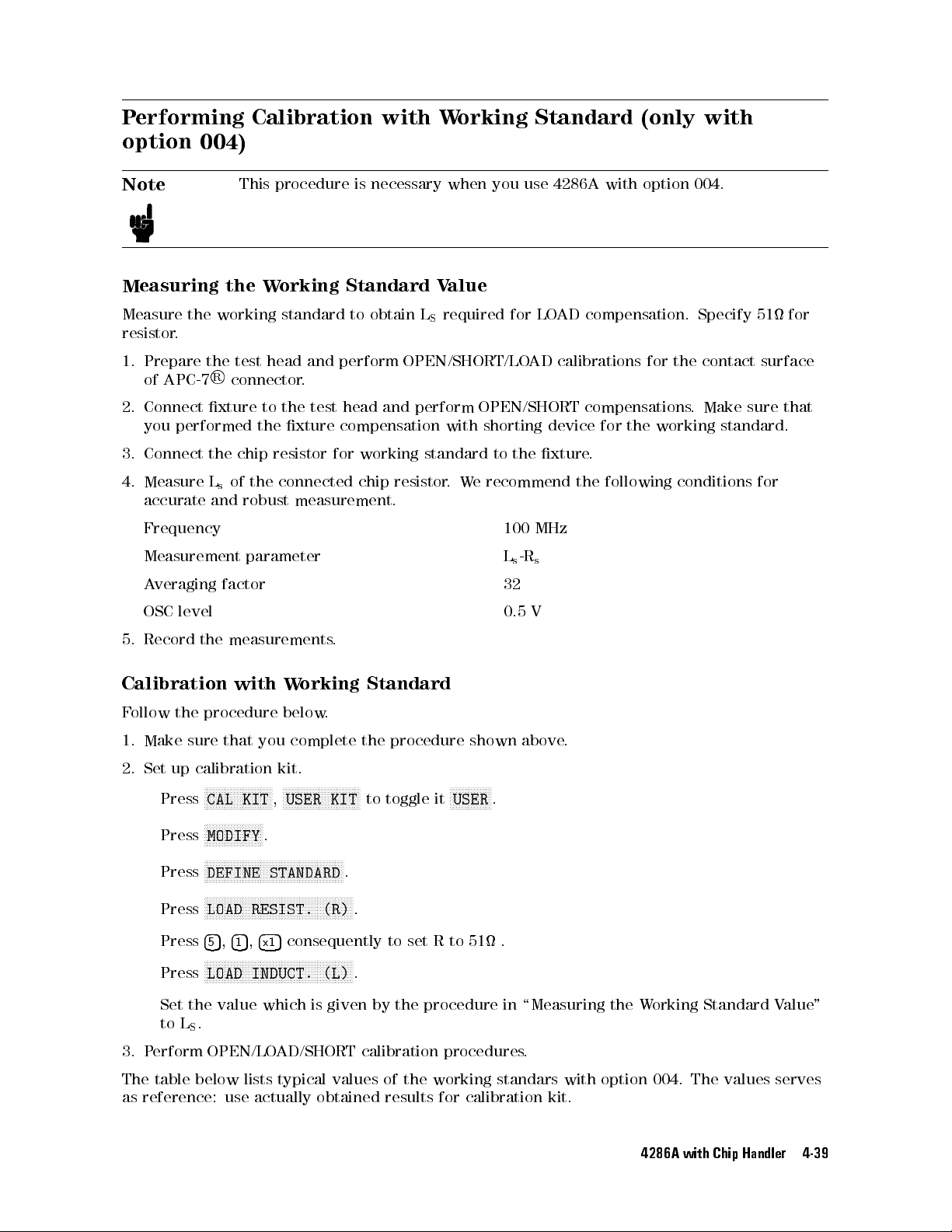
Performing
option
004)
Calibration with
Working
Standard (only
with
Note
This procedure
Measuring the
Measure the
working standard
Working
is necessary
Standard V
to
obtain
L
S
when you
alue
required for
resistor.
1. Prepare
of APC-7
2. Connect
you
3.
Connect
4.
Measure
accurate
the test
R
connector.
xture
performed
the chip
of
L
s
and
head
to
the
resistor
the
robust
and
perform
the
test
head
xture
compensation
for
connected
measurement.
OPEN/SHORT/LO
and
perform
working
chip
standard
resistor
with
.
We
Frequency 100
Measurement parameter
A
veraging
OSC
factor 32
level
use 4286A
LOAD
AD
calibrations
OPEN/SHORT
shorting
to
the
device
xture
recommend the
MHz
L
s-Rs
0.5
V
with option
004.
compensation.
for
the
compensations
for
the
.
working
.
following conditions
Specify
contact
Make
standard.
51
surface
sure
for
for
that
5.
Record
Calibration
F
ollow
1.
Make
2.
Set
the
measurements
with
the
procedure
sure
that
up
calibration
N
N
N
N
N
N
N
N
N
N
N
N
N
N
CAL
Press
Press
Press
KIT
NN
NN
NN
NN
NN
NN
N
N
MODIFY
NNNNNNNNNNNNN
NNNNNNNNNNNNNNNNNNNNNNNNN
DEFINE STANDARD
NNNNNNNNNNNNNNNNNNNNNNN
Press
LOAD RESIST. (R)
5
5
Press
Press
,
4
4
1
5
NNNNNNNNNNNN
NNNNNNNNNNNNNNNNNNNNNNNNN
LOAD INDUCT. (L)
W
below
you
kit.
N
N
N
N
NN
NN
NN
N
USER
,
N
N
N
N
N
N
.
NNNNNNNNNNNNNNNNNNNNNNNNN
5
consequently
,
4
x1
.
orking
.
complete
N
N
N
N
N
N
N
N
N
N
N
N
N
N
NN
NN
KIT
NNNNNNNNN
NNNNNNNNNNNNN
Standard
the
procedure
NN
NN
N
N
to
toggle
.
NN
.
to set R to 51 .
.
it
shown
N
N
N
N
N
N
N
USER
above
.
N
N
N
N
N
N
N
.
Set the value which is given by the procedure in \Measuring the Working Standard Value"
to LS.
3. Perform OPEN/LOAD/SHORT calibration procedures.
The table below lists typical values of the working standars with option 004. The values serves
as reference: use actually obtained results for calibration kit.
4286A with Chip Handler 4-39
Page 86
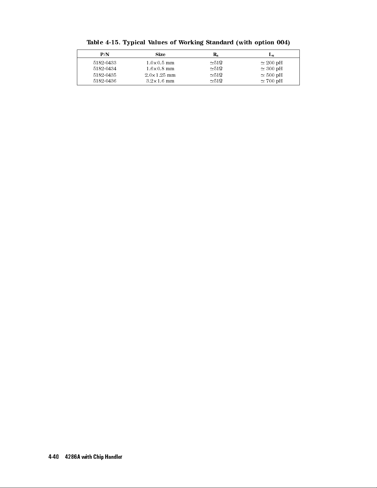
T
able 4-15.
Typical V
alues
of
W
orking
Standard
(with
option
004)
P/N Size
5182-0433
5182-0434
1.0
1.6
5182-0435 2.0
5182-0436
3.2
2
0.5
2
0.8 mm
2
1.25
2
1.6
mm
mm
mm
'
'
'
'
L
s
200 pH
300
pH
500
pH
700 pH
R
s
'
51
'
51
'
51
'
51
4-40 4286A with Chip Handler
Page 87
Restoring Settings
After P
ower Interruption
Instantaneous
therefore
the
settings
When
on
is
running.
memory
calibration
backup
.
you
a
exible
.
,
be
In
SRAM
wish
disk.
When
either
data
4286A settings
Note
power
set
interruption
to your
disk
to
use the
Then, insert
you
case,
if
the
after power
When
memory
All
data
Backup
own settings
memory or
exible disk
wish to
use the
the 4286A
power is
interruption.
you
have
,
the
contents
in
the
batteries
resets
the 4286A
again after
built-in exible
drive,
this disk
in the
SRAM disk
will read
interrupted. A
the
AUTOREC
of
the
disk
memory
can
be
automatically
to default
power interruption.
disk drive
rst save
disk drive
the contents
your
memory,
and
save
of
utoRecall provides
le
le
will
stored
in
be
the
lost
in
both
exible
in
3
recharged
settings.
The 4286A
To
do this
to automatically
settings
keep
this
days
the
le
the
disk
in
it
AUTOREC
to
a fast
exible
will
after
when
the
inserted
recall
way
be
power
the
must,
,you
restore your
le
named
while
le
on
its
settings
to
recover
disk
and
read
into
interruption.
4286A
is
can
use
AUTOREC
the
4286A
the
disk
and
your
RAM
disk
the 4286A
ON.
.
4286A with Chip Handler 4-41
Page 88

Page 89
5
Typical
The 4286A
This chapter
Functions
has
a
number
describes
functions.
Functions available
become
associated
Key
familiar
section.
F
eatures:
with
Measurement-related
P
oint
P
oint
OSC
Delay
A
Level
and
veraging
Monitor
Display-related Function:
Entering
Other
Saving
Printing
Logging
Titles
Functions
and
Recalling
or
Plotting
Key
of
the
major
with
the
the
description
Functions:
Sweep
on
the
Sequence
functions
features
4286A
Delay
Screen
into
a
other
of
are
listed
of
that
Program
than
those
and
operation
below
function
(Option
explained
.
If
you
and
1C2
procedures
nd
a
its
key
Only)
in
the
previous
associated
function
operation
chapters
with
that
suits
sequence
these
your
in
the
.
task,
Typical Functions 5-1
Page 90
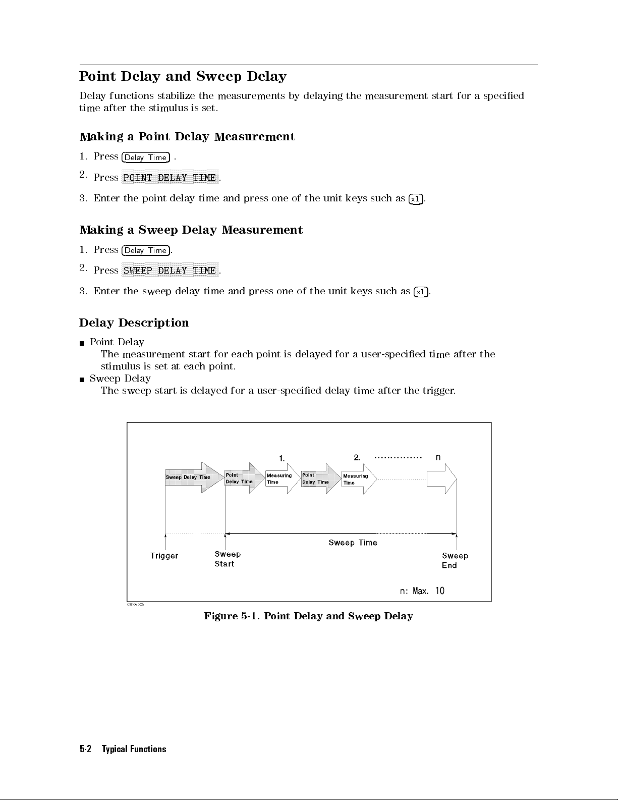
Point
Delay
time
after
Delay and
functions
the
stabilize
stimulus
Sweep Delay
the
measurements by
is set.
delaying the
measurement start
for a
specied
Making a
1.
Press
4
Dela
N
N
Press
N
POINT
the point
2.
3. Enter
Making
1. Press
2.
3.
Delay
P
4
Delay
N
N
N
Press
Enter
SWEEP
the
Description
oint Delay
The
measurement start
stimulus
Sweep
The
Delay
sweep
P
oint
y
N
N
NN
NN
NN
NN
N
a
Sweep
N
N
N
N
N
N
N
N
N
N
N
sweep
is
Time
N
N
N
N
N
Time
N
N
N
NN
set
start
Delay
5
.
N
N
N
N
N
N
N
N
N
N
N
DELAY
delay
5
.
NN
NN
N
N
N
N
N
N
N
DELAY
delay
at each
Measurement
NN
NN
NN
NN
N
N
N
N
N
N
N
N
N
N
N
TIME
time
Delay
N
N
N
N
N
N
N
N
N
N
N
N
NN
NN
NN
N
TIME
time
for each
point.
is
delayed for
N
.
and
press
one
Measurement
N
.
and
press
one
point
is
a
user-specied
of
the
of
the
delayed
unit
unit
for
delay
keys
such
keys such
a
user-specied
time
after
as
as
4
the
5
.
x1
4
x1
trigger
5
.
time
after
.
the
5-2 Typical Functions
Figure 5-1. P
oint
Delay and Sweep Delay
Page 91
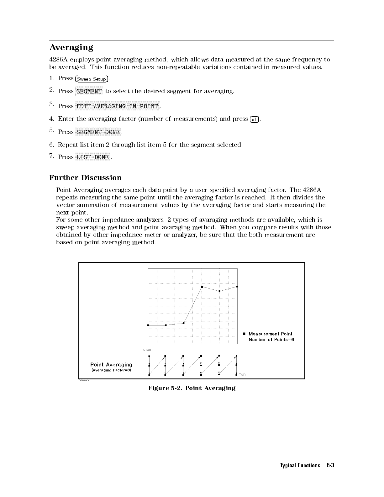
Averaging
4286A
be
1.
2.
3.
4.
5.
6.
7.
employs
averaged.
Press
Press
Press
Enter
Press
Repeat list
Press
Further
P
oint
A
repeats
vector
next
point.
F
or
some
sweep
obtained
based
point
This
function
4
Sw
eep
Setup
NN
NN
NN
NN
NN
N
N
N
N
N
N
N
N
N
N
N
N
N
SEGMENT
NN
NN
N
NN
NN
EDIT
the
N
N
N
N
N
N
N
N
N
N
N
N
N
AVERAGING ON
averaging
N
N
NN
NN
NN
NN
N
N
N
N
N
N
N
N
N
N
N
N
N
N
N
N
N
N
SEGMENT
item 2
NN
NN
NN
N
N
N
N
N
N
N
N
N
N
N
N
N
N
N
N
N
N
N
LIST DONE
Discussion
veraging
measuring
summation
other
impedance
averaging
by
other
on
point
averaging
averaging
5
.
to
select the
N
N
N
N
N
N
N
N
N
N
NN
NN
NN
NN
factor
N
N
N
N
N
NN
NN
NN
NN
DONE
.
through
NN
NN
.
averages
the
same
of
measurement
method
impedance
method, which
reduces non-repeatable
desired segment
N
N
N
N
N
N
N
N
N
N
N
N
N
N
N
N
N
NN
NN
NN
NN
N
N
POINT
(number
list
each
point
analyzers
and
item
data
point
meter
.
of
measurements)
5
for
the
point
by
until
the
values
,
2
by
types
avaraging
or
analyzer
averaging
method.
allows data
measured at
variations contained
for
averaging.
and
segment
a
user-specied
selected.
factor
the
averaging
of
avaraging methods
method.
,
be
sure
When
that
the same
in measured
5
press
.
4
x1
averaging
is
reached.
factor
and
starts
are available
you
compare
the
both measurement
factor
It
then
results
frequency to
values.
.
The
4286A
divides
measuring
,
which
with
are
the
the
is
those
Figure 5-2. P
oint A
veraging
Typical Functions 5-3
Page 92
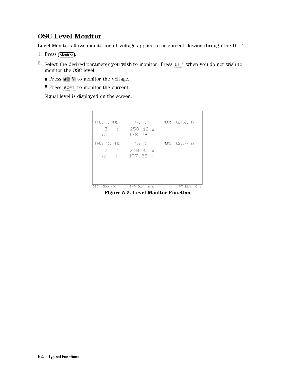
OSC Level
Level
Monitor
Monitor
allows
monitoring
of voltage
applied to
or current
owing through
the DUT
.
1.
Press
2.
Select the
monitor
Press
Press
Signal
5
4
Monito
.
r
desired parameter
the
OSC
N
N
N
N
NN
to
NN
NN
N
N
to
is
displayed
level.
monitor
monitor the
N
N
N
N
AC-V
N
N
N
N
AC-I
level
N
N
N
N
NN
NN
the
on
the
Figure
you wish
voltage
.
current.
screen.
5-3.
to monitor
Level
Monitor
. Press
NN
NN
NN
NN
NN
N
OFF
when
Function
you do
not wish
to
5-4 Typical Functions
Page 93
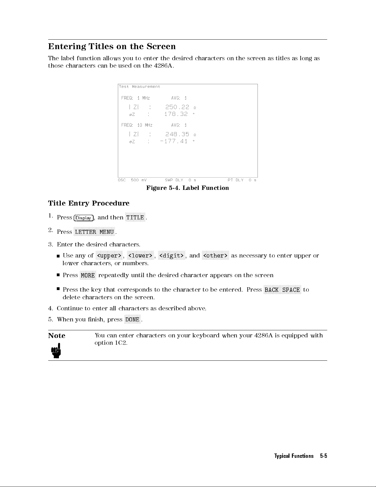
Entering Titles
The
label
those
function
characters
allows
can
on the
you to
be
used on
Screen
enter the
the 4286A
desired characters
.
on the
screen as
titles as
long as
Title
1.
2.
3.
Entry
Press
Press
Enter
Use
4
Displa
N
N
N
N
LETTER MENU
the
any
lower characters
Press
Press the
delete
4.
Continue
5.
When
you
Note
Figure
5-4.
Label
Function
Procedure
N
N
N
N
N
N
N
N
N
N
N
N
N
N
N
N
N
5
,
and
y
NN
N
N
N
N
N
N
N
N
N
N
N
N
N
N
N
N
N
N
N
N
N
N
N
then
NN
N
N
N
N
TITLE
.
.
desired
of
N
N
N
N
N
N
N
N
N
MORE
characters
to
nish,
N
N
N
N
N
N
N
N
N
N
N
<upper>
N
N
N
N
N
repeatedly
key
that
enter
press
characters
N
N
N
N
N
N
N
N
N
N
N
N
<lower>
,
numbers
N
NN
N
N
N
N
,
or
until
corresponds
on
the
all
characters
N
N
N
N
N
N
N
N
N
DONE
.
N
N
N
N
NN
N
N
N
N
N
N
N
.
the
screen.
NN
NN
N
.
N
N
N
N
N
N
N
N
N
<digit>
,
desired
to
the
as
described
N
N
N
N
N
NN
N
N
N
N
N
N
character
N
,
and
N
<other>
N
N
N
character
to
above
N
N
N
N
N
N
N
N
N
appears
be
.
N
NN
N
N
N
N
N
N
N
N
N
entered.
N
as
on
necessary
the
screen
Press
to
enter
NN
NN
NN
N
N
N
N
N
N
N
N
N
N
N
N
N
N
BACK SPACE
You can enter characters on your keyboard when your 4286A is equipped with
option 1C2.
N
N
N
NN
upper
NN
NN
NN
N
to
or
Typical Functions 5-5
Page 94
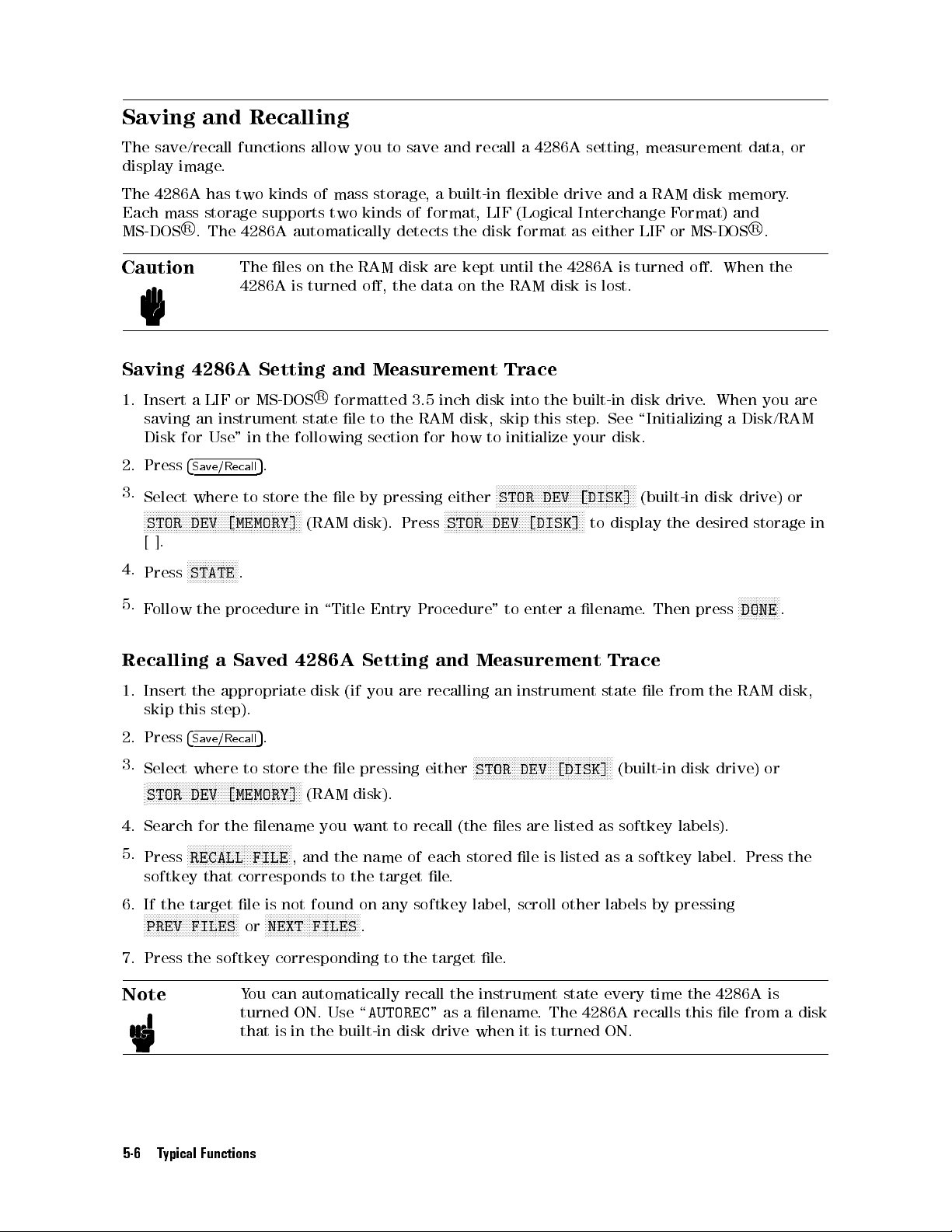
Saving and
The
save/recall
display
The
Each
MS-DOS
Caution
image
4286A
mass
R
.
has
storage
.
The
Recalling
functions
two
kinds of
supports
4286A
The
4286A
automatically
les
on
is
turned
allow
you to
mass storage
two
kinds
the
RAM
save and
,a
built-in exible
of
format,
detects the
disk
are
the
data
recall a
LIF (Logical
disk format
kept
until
on
the
4286A setting,
drive and
Interchange F
as either
the
4286A
RAM
disk
is
measurement data,
aRAM
ormat) and
LIF or
is
turned
lost.
disk memory
R
MS-DOS
o.
.
When
or
.
the
Saving 4286A
1.
Insert
saving
Disk
2. Press
3.
Select
N
[
4.
Press
5.
F
Recalling
1.
Insert
skip
2.
Press
3.
Select
N
N
N
N
N
N
N
NN
STOR
].
ollow
N
N
N
N
N
N
N
N
STOR
a
an
for
4
Save/Recall
where to
NN
NN
NN
N
N
N
N
N
DEV
NN
N
N
N
STATE
the
the
this
4
Save/Recall
where
N
N
N
N
NN
NN
NN
NN
DEV
LIF
or
instrument
Use
"
N
N
N
N
N
N
N
N
N
N
N
N
NN
[MEMORY]
N
N
N
N
N
N
N
N
N
N
N
N
.
procedure
a
Saved 4286A
appropriate
step).
N
N
N
N
N
N
N
N
N
N
N
N
[MEMORY]
Setting and
R
following
N
N
N
N
N
N
N
N
N
N
N
NN
NN
N
N
N
N
N
N
N
state
(RAM
in
disk
the
(RAM
MS-DOS
in
the
5
.
store the
NN
NN
NN
N
N
5
.
to
store
N
N
N
N
N
NN
NN
Measurement
formatted
le
to
section
le by
disk).
\Title
Entry
Setting and
(if
you
le
pressing
disk).
3.5
inch
disk
the
RAM
disk,
for
how
pressing either
Press
Procedure
are
recalling
either
N
N
N
N
N
N
N
NN
NN
NN
STOR
Measurement
N
N
N
STOR
Trace
into
the
skip
this
to
initialize
N
N
N
N
N
NN
NN
NN
N
N
N
N
N
N
N
N
N
N
STOR
NN
N
N
N
N
N
N
N
N
DEV
"
to
an instrument
N
N
N
N
N
N
N
N
N
N
N
N
DEV [DISK]
N
N
N
N
N
N
N
N
N
NN
NN
NN
NN
[DISK]
enter
N
N
N
N
N
NN
NN
NN
N
N
N
N
N
DEV
[DISK]
built-in
step
your
N
N
N
N
N
N
N
N
N
NN
N
N
N
N
N
N
N
to
a
lename
N
N
N
N
N
N
N
N
N
N
disk
.
See
disk.
NN
NN
N
N
N
N
N
N
N
N
N
display
Trace
state le
N
N
N
N
NN
N
(built-in
drive
.
\Initializing
N
(built-in disk
the desired
.
Then press
from
disk
When
a
the
drive)
you
are
Disk/RAM
drive) or
storage in
N
N
N
N
N
N
N
N
N
N
N
N
N
N
DONE
.
RAM
disk,
or
4. Search
5.
Press
softkey that corresponds to the target le
6. If the target le is not found on any softkey label, scroll other labels by pressing
NNNNNNNNNNNNNNNNNNN
PREV FILES
7. Press the softkey corresponding to the target le
Note
5-6 Typical Functions
for the
N
N
N
N
N
N
N
RECALL FILE
NNNNNNNNNNNNN
lename you
N
N
N
N
N
NN
N
N
N
N
N
N
N
N
N
N
NN
N
N
NNNNNNNNNNNNNNNNNNN
NEXT FILES
or
You can automatically recall the instrument state every time the 4286A is
turned ON. Use \
that is in the built-in disk drive when it is turned ON.
want to
N
N
N
N
N
N
N
, and the name of each stored le is listed as a softkey
NNNNNNNNNNNNN
.
recall
AUTOREC
(the
les
are
listed
as
softkey
.
.
" as a lename. The 4286A recalls this le from a disk
labels).
label. Press the
Page 95
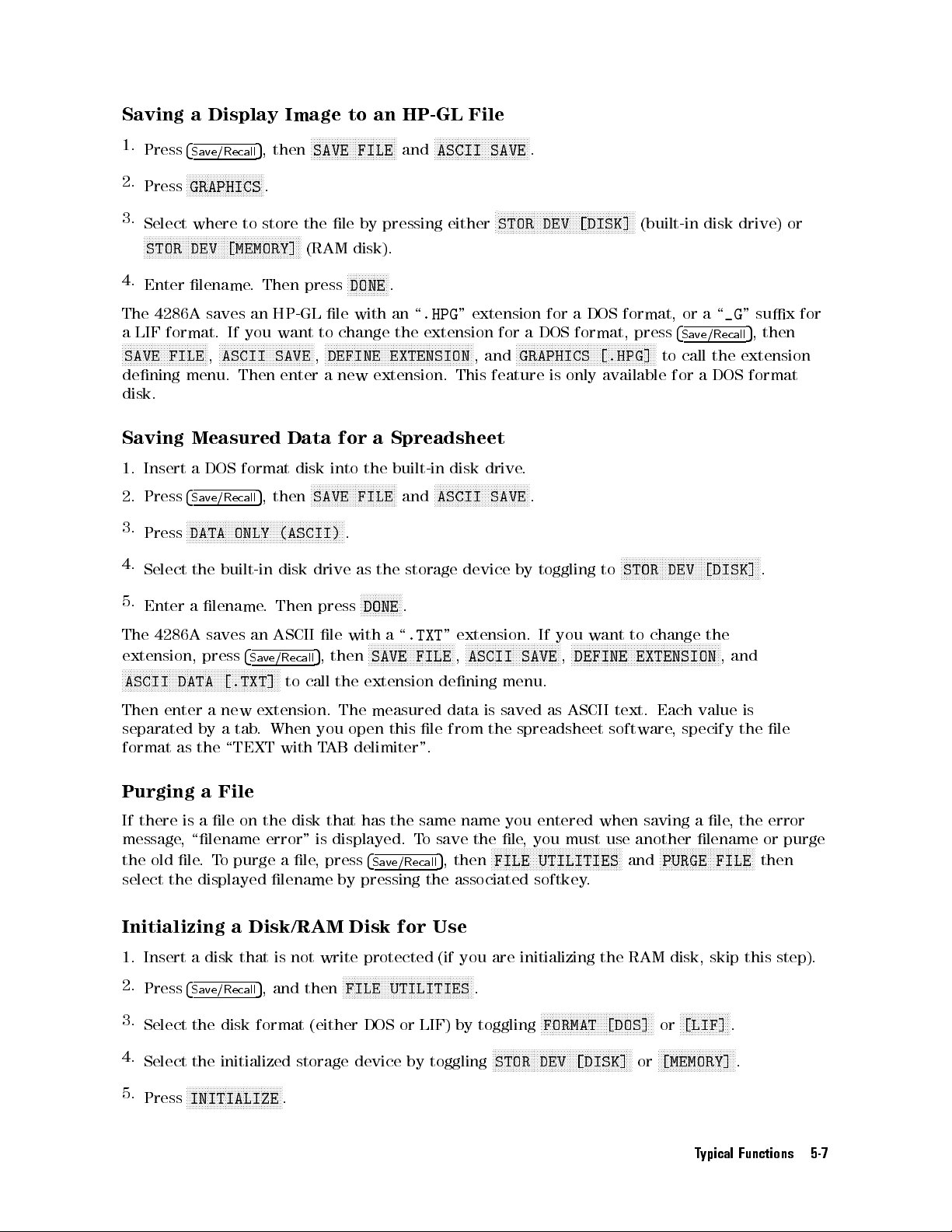
Saving
1.
Press
2.
Press
3.
Select
N
4.
Enter
The
a
LIF
N
N
N
N
N
N
N
N
SAVE
dening menu.
disk.
N
N
N
N
N
N
N
N
N
STOR
4286A
format.
N
N
N
N
N
N
N
NN
FILE
a
Display
4
Save/Recall
N
NN
NN
NN
NN
NN
GRAPHICS
where to
N
N
N
N
N
NN
NN
NN
NN
N
DEV
lename
saves
NN
NN
N
N
N
N
N
N
N
N
,
N
N
5
,
then
N
N
N
N
N
N
N
N
N
N
N
NN
NN
.
store
N
N
N
N
N
N
N
N
N
N
N
N
N
N
NN
NN
[MEMORY]
.
Then
an
HP-GL
If
you
N
N
N
N
N
N
N
N
N
N
N
N
N
N
N
NN
ASCII
NN
Then
Image
the
NN
NN
N
N
N
N
N
press
want
NN
N
N
N
N
N
N
N
N
N
SAVE
enter
N
N
N
N
N
NN
NN
SAVE
le
(RAM
le
to
N
N
N
N
N
N
DEFINE
,
a
to
NN
NN
NN
NN
NN
N
N
FILE
by
disk).
N
N
N
N
N
N
N
N
N
DONE
with
change
N
N
N
N
N
N
N
N
N
N
N
NN
new
extension.
an
HP-GL
N
N
N
N
N
N
N
N
and
pressing
N
N
NN
N
.
an
\
.HPG
the
NN
extension
NN
N
N
N
N
N
N
N
N
N
N
N
N
N
N
EXTENSION
N
N
N
N
N
NN
ASCII
either
N
N
N
N
N
NN
NN
File
NN
NN
NN
NN
NN
NN
N
N
SAVE
"
extension
NN
N
N
N
N
,
and
This
feature
N
N
N
N
N
N
N
N
N
NN
.
N
N
NN
NN
NN
N
N
N
N
N
STOR
for
a
N
N
N
N
N
N
GRAPHICS
N
N
N
N
N
N
NN
NN
NN
NN
NN
NN
NN
N
N
a
format,
N
N
NN
NN
NN
only
N
DOS
N
N
N
N
N
N
N
N
[.HPG]
available
DEV [DISK]
for
DOS
N
N
N
N
N
N
N
is
N
N
N
N
N
N
N
N
format,
N
N
N
N
N
N
N
N
NN
N
(built-in
press
N
N
N
NN
NN
NN
N
or
4
Save/Recall
to
call
for
disk
a\
the
a
DOS
drive)
_G
"
sux for
5
,
then
extension
format
or
Saving
1.
Insert
2.
Press
3.
Press
4.
Select
5.
Enter a
The
extension,
N
N
N
N
N
N
N
N
ASCII
Then
separated by
format as
Purging
If
there is
message
the old le
select
Measured
a
DOS
format
4
Save/Recall
NN
NN
N
N
N
N
N
N
N
N
N
N
N
N
N
N
DATA
the
4286A
N
N
N
N
N
NN
NN
N
N
N
N
N
N
N
N
DATA
enter
,
\lename
the displayed lename by pressing the associated softkey
N
ONLY
built-in
lename
saves
press
N
N
N
N
N
N
N
N
N
N
N
N
N
NN
[.TXT]
a
new
atab
the \TEXT
a
File
ale
on
.T
o purge a le
Data
5
,
then
N
N
N
N
N
N
NN
NN
N
N
N
N
N
N
(ASCII)
disk
.
Then
an
ASCII
4
Save/Recall
NN
N
N
N
N
N
N
N
N
N
N
N
to
extension.
. When
with T
the
error" is
disk
N
N
N
N
N
N
call
disk
N
N
for
into
N
N
N
N
N
N
N
N
N
N
N
N
N
NN
SAVE
N
N
N
N
N
N
N
N
NN
N
.
drive
press
le
with
5
,
then
the
The
you
open
AB
that
displayed.
, press
a
Spreadsheet
the
built-in
NN
NN
N
N
N
N
N
N
N
N
N
FILE
and
as
the
storage device
N
N
N
NN
N
N
N
N
N
N
N
N
N
DONE
.
a
\
.TXT
N
N
N
N
N
N
N
N
N
N
N
N
N
N
N
N
N
N
N
this
the
NN
FILE
le
same
T
o
SAVE
extension
measured data
delimiter".
has
4
Save/Recall
disk
N
N
N
N
N
N
N
N
N
N
N
N
ASCII
"
extension.
N
N
N
N
N
N
N
N
N
ASCII
,
dening
from
name
save
5
,then
N
N
N
N
the
NN
NN
N
N
N
drive.
NN
N
N
N
N
N
N
N
N
N
N
N
N
SAVE
.
by
toggling
If
you
N
N
N
N
N
N
N
N
N
N
N
N
N
N
N
N
N
NN
N
N
N
SAVE
menu.
is saved
the
spreadsheet
you
le
,
you
NNNNNNNNNNNNNNNNNNNNNNNNN
FILE UTILITIES
N
N
N
N
N
N
N
N
DEFINE
,
as ASCII
entered
must
NNNNNNNNNNNNNNNNNNN
N
N
STOR
to
want
N
N
N
N
N
N
N
N
N
N
N
N
N
text. Each
software
when
use
.
N
N
N
N
N
N
N
N
NN
NN
N
N
N
N
N
N
N
DEV
to
change
N
NN
N
N
N
N
N
N
N
N
N
N
N
N
N
N
N
N
EXTENSION
,
saving a
another
NNNNNNNNNNNNNNNNNNNNNNNNN
PURGE FILE
and
N
N
N
N
N
N
N
N
N
N
N
N
N
N
NN
NN
N
[DISK]
the
N
N
N
N
N
N
N
NN
N
N
N
N
,
and
value
specify
le,
lename or
NNNNNNN
N
N
N
N
N
N
N
N
.
is
the
le
the error
purge
then
Initializing a Disk/RAM Disk for Use
1. Insert a disk that is not
2.
Press
4
Save/Recall
3.
Select the disk format (either DOS or LIF) by toggling
4.
Select the initialized storage device by toggling
Press
NNNNNNNNNNNNNNNNNNNNNNNNNNNNNNNN
INITIALIZE
5.
5
, and then
write protected (if you are initializing the RAM disk, skip this step).
NNNNNNNNNNNNNNNNNN
FILE UTILITIES
.
NNNNNNNNNNNNNNNNNNNNNNNNN
N
.
NNNNNNNNNNNNNNNNNNNNNNNNNNNNNNNNNNNNNN
FORMAT [DOS]
NNNNNNNNNNNNNNNNNNNNNNNNNNNNNNNNNNNNNNNNNNNNNNN
STOR DEV [DISK]
NNNNNNNNNNNNNNNNN
or
[LIF]
NNNNNNNNNNNNNNNNNNNNNNNNNN
or
[MEMORY]
.
.
Typical Functions 5-7
Page 96

6.
Press
N
NN
NN
NN
NN
NN
NN
N
N
N
N
N
N
N
N
N
N
N
N
INITIALIZE
N
NN
NN
NN
NN
NN
NN
N
DISK: YES
N
N
N
N
N
N
N
N
N
N
N
N
NN
NN
NN
NN
NN
N
to initialize
the RAM
disk or
the disk.
5-8 Typical Functions
Page 97
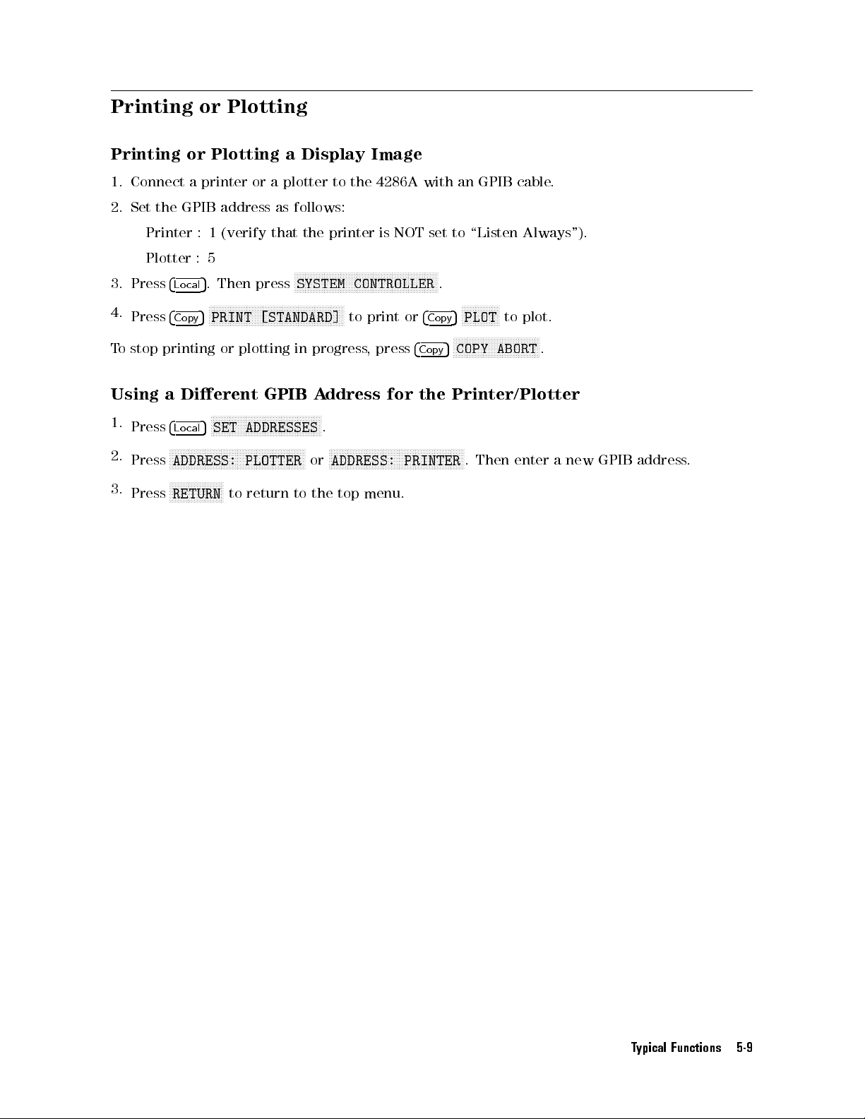
Printing or
Plotting
Printing
1.
Connect a
2.
Set the
Printer
Plotter
3.
Press
4
4.
Press
4
T
o
stop
printing
Using
1.
2.
3.
a Dierent
Press
4
N
Press
N
Press
or
Plotting a
printer or
GPIB address
:1
(verify that
:5
5
. Then
Lo
cal
N
N
N
N
N
N
N
N
N
N
N
PRINT
5
Cop
y
or
N
N
NN
N
N
N
N
N
N
N
SET ADDRESSES
5
Lo
cal
N
N
N
N
N
N
N
N
N
N
N
N
NN
NN
NN
NN
N
N
N
N
ADDRESS:
NN
N
N
N
N
N
N
N
RETURN
N
N
N
N
N
N
N
N
N
N
N
to
a plotter
as
press
N
N
N
N
N
NN
NN
NN
NN
N
N
N
N
N
N
[STANDARD]
plotting
GPIB
N
N
N
N
N
N
N
N
N
N
N
N
N
N
N
N
NN
N
N
N
N
N
N
N
N
N
N
N
N
NN
NN
NN
PLOTTER
return
Display Image
follows:
the
N
NN
NN
NN
N
N
N
N
N
SYSTEM
N
N
N
N
N
N
N
N
N
N
N
NN
in
progress
A
N
N
N
N
N
N
N
N
N
N
N
N
.
NN
N
N
N
N
or
to
the
to the
printer
N
N
N
NN
NN
ddress
N
N
N
ADDRESS:
4286A with
is
N
N
N
N
N
N
N
N
N
NN
NN
NN
NN
N
N
CONTROLLER
NN
N
to
print
,
press
N
N
N
N
N
N
N
N
N
N
NN
NN
NN
NN
N
top
menu.
NOT
N
N
N
N
N
N
N
N
N
N
N
or
4
for
N
N
N
N
N
N
N
N
N
N
PRINTER
an
GPIB
set
to
\Listen
N
N
N
N
NN
NN
.
N
N
N
N
N
N
N
N
N
N
N
N
N
PLOT
5
4
Cop
y
N
N
N
N
N
N
N
N
N
N
N
N
N
N
N
NN
COPY
5
Cop
y
the
Printer/Plotter
N
N
N
N
N
N
NN
NN
NN
NN
N
N
N
N
.
Then
cable
Always").
N
to
plot.
NN
NN
N
N
N
N
N
N
ABORT
enter
.
N
N
N
N
N
.
a
new
GPIB
address
.
Typical Functions 5-9
Page 98
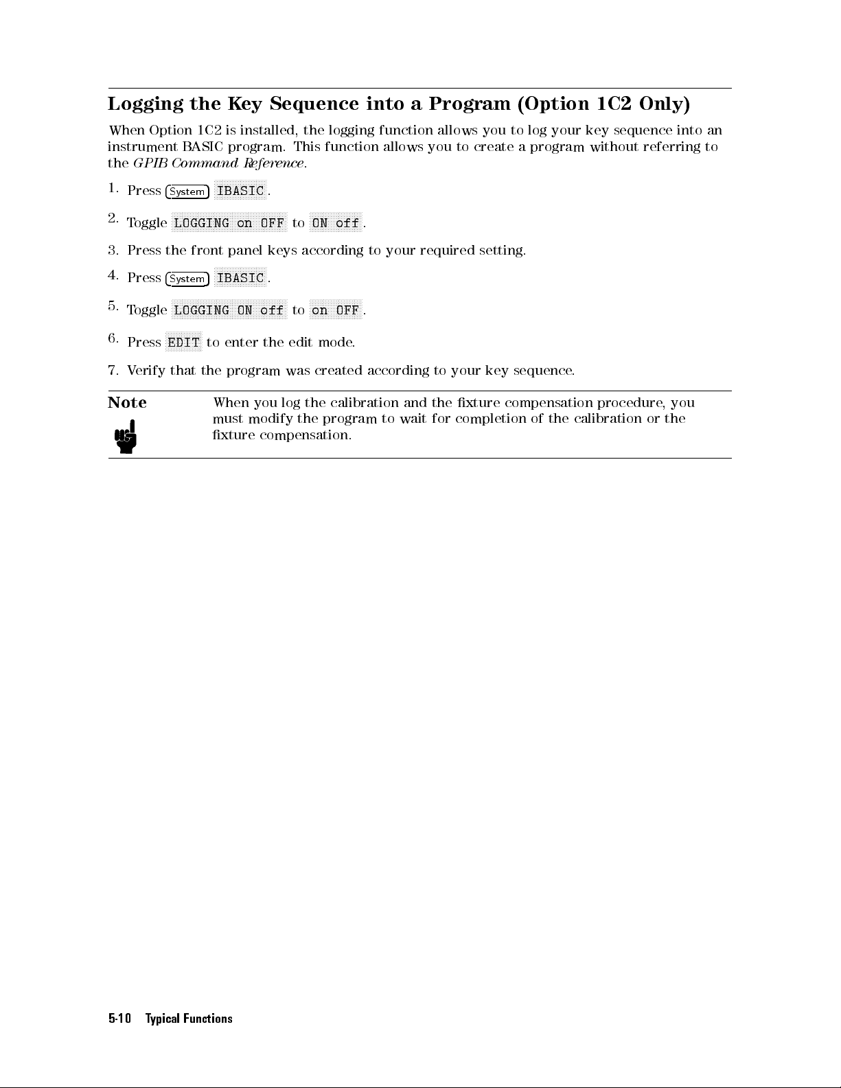
Logging the
When
Option
instrument
the
GPIB
1.
Press
2.
T
oggle
3.
Press
4.
Press
5.
T
oggle
6.
Press
7.
V
erify
1C2
B
ASIC
Command
5
4
System
N
N
N
N
N
NN
NN
NN
NN
N
N
LOGGING
the
front
4
5
System
N
N
N
N
N
N
N
N
N
N
N
N
N
N
N
LOGGING
N
N
N
N
N
N
N
N
NN
NN
N
EDIT
to
that the
Key
is
installed, the
program.
R
eference
N
N
N
N
N
N
N
N
N
NN
NN
NN
NN
NN
N
N
N
N
N
N
N
N
N
on
panel
NN
N
N
N
N
N
N
N
NN
N
N
N
N
N
N
ON
enter
N
N
N
NN
N
N
N
N
N
NN
NN
OFF
N
N
N
N
N
N
N
N
off
the
.
NN
keys
.
N
IBASIC
N
N
N
N
N
NN
NN
IBASIC
N
N
NN
NN
program was
Sequence into
logging function
This function
allows you
.
N
N
N
N
N
NN
NN
NN
NN
N
N
N
N
N
N
N
N
N
N
N
N
N
N
N
N
N
NN
ON
to
according
N
N
N
N
on
to
edit
mode
created
N
off
.
to
your
N
N
N
N
N
N
N
N
N
N
N
N
N
NN
N
OFF
.
.
according
a Program
allows you
to create
required
to
your
setting.
key
(Option 1C2
to log
your key
a program
sequence
without referring
.
Only)
sequence into
an
to
Note
When
must
xture
you
log
the
modify
the
compensation.
calibration
program
to
and
wait
the
xture
for
completion
compensation
of
the
calibration
procedure
or
,
the
you
5-10 Typical Functions
Page 99
Resetting the
4286A
Press
See
Function R
4
Preset
5
to reset
all function
eference
for
preset
parameters
values
.
to
the
preset
values
.
Typical Functions 5-11
Page 100

 Loading...